US9578724B1 - Illumination device and method for avoiding flicker - Google Patents
Illumination device and method for avoiding flickerDownload PDFInfo
- Publication number
- US9578724B1 US9578724B1US13/970,990US201313970990AUS9578724B1US 9578724 B1US9578724 B1US 9578724B1US 201313970990 AUS201313970990 AUS 201313970990AUS 9578724 B1US9578724 B1US 9578724B1
- Authority
- US
- United States
- Prior art keywords
- led
- leds
- luminous flux
- illumination device
- drive current
- Prior art date
- Legal status (The legal status is an assumption and is not a legal conclusion. Google has not performed a legal analysis and makes no representation as to the accuracy of the status listed.)
- Ceased, expires
Links
Images


Classifications
- H05B37/0281—
- H—ELECTRICITY
- H04—ELECTRIC COMMUNICATION TECHNIQUE
- H04B—TRANSMISSION
- H04B10/00—Transmission systems employing electromagnetic waves other than radio-waves, e.g. infrared, visible or ultraviolet light, or employing corpuscular radiation, e.g. quantum communication
- H04B10/11—Arrangements specific to free-space transmission, i.e. transmission through air or vacuum
- H04B10/114—Indoor or close-range type systems
- H04B10/116—Visible light communication
- H—ELECTRICITY
- H05—ELECTRIC TECHNIQUES NOT OTHERWISE PROVIDED FOR
- H05B—ELECTRIC HEATING; ELECTRIC LIGHT SOURCES NOT OTHERWISE PROVIDED FOR; CIRCUIT ARRANGEMENTS FOR ELECTRIC LIGHT SOURCES, IN GENERAL
- H05B45/00—Circuit arrangements for operating light-emitting diodes [LED]
- H05B45/20—Controlling the colour of the light
- H05B45/22—Controlling the colour of the light using optical feedback
- H—ELECTRICITY
- H05—ELECTRIC TECHNIQUES NOT OTHERWISE PROVIDED FOR
- H05B—ELECTRIC HEATING; ELECTRIC LIGHT SOURCES NOT OTHERWISE PROVIDED FOR; CIRCUIT ARRANGEMENTS FOR ELECTRIC LIGHT SOURCES, IN GENERAL
- H05B45/00—Circuit arrangements for operating light-emitting diodes [LED]
- H05B45/20—Controlling the colour of the light
- H05B45/28—Controlling the colour of the light using temperature feedback
- H—ELECTRICITY
- H05—ELECTRIC TECHNIQUES NOT OTHERWISE PROVIDED FOR
- H05B—ELECTRIC HEATING; ELECTRIC LIGHT SOURCES NOT OTHERWISE PROVIDED FOR; CIRCUIT ARRANGEMENTS FOR ELECTRIC LIGHT SOURCES, IN GENERAL
- H05B45/00—Circuit arrangements for operating light-emitting diodes [LED]
- H05B45/30—Driver circuits
- H05B45/37—Converter circuits
- H05B45/3725—Switched mode power supply [SMPS]
- H05B45/375—Switched mode power supply [SMPS] using buck topology
Definitions
- This inventionrelates to illumination devices and, more particularly, to illumination devices comprising a plurality of light emitting diodes (LEDs) and to methods for calibrating and compensating individual LEDs in an illumination device, so as to maintain a desired luminous flux and/or a desired color point of the device over variations in temperature and process while avoiding undesirable visual artifacts, such as brightness banding and flicker.
- LEDslight emitting diodes
- LEDslight emitting diodes
- LEDsprovide a number of advantages over traditional light sources, such as incandescent and fluorescent light bulbs, including low power consumption, long lifetime, no hazardous materials, and additional specific advantages for different applications.
- LEDsWhen used for general illumination, LEDs provide the opportunity to adjust the color (e.g., from white, to blue, to green, etc.) or the color temperature (e.g., from “warm white” to “cool white”) to produce different lighting effects.
- LEDsare rapidly replacing the Cold Cathode Fluorescent Lamps (CCFL) conventionally used in many display applications (such as LCD backlights), due to the smaller form factor and wider color gamut provided by LEDs.
- Organic LEDsOLEDs
- OLEDswhich use arrays of multi-colored organic LEDs to produce light for each display pixel, are also becoming popular for many types of display devices.
- LEDshave many advantages over conventional light sources, a disadvantage of LEDs is that their output characteristics tend to vary over temperature, process and time.
- the luminous fluxor the perceived power of light emitted by an LED, is directly proportional to the drive current supplied thereto.
- the luminous flux of an LEDis controlled by increasing/decreasing the drive current supplied to the LED to correspondingly increase/decrease the luminous flux.
- the luminous flux generated by an LED for a given drive currentdoes not remain constant over temperature and time, and gradually decreases with increasing temperature and as the LED ages over time.
- the luminous fluxtends to vary from batch-to-batch, and even from one LED to another in the same batch, due to process variations.
- LED manufacturerstry to compensate for process variations by sorting or binning the LEDs based on factory measured characteristics, such as chromacity (or color), luminous flux and forward voltage.
- factory measured characteristicssuch as chromacity (or color), luminous flux and forward voltage.
- binning alonecannot compensate for changes in LED output characteristics due to aging and temperature fluctuations during use of the LED device.
- temperature compensationis currently implemented in today's LED devices.
- most temperature compensation methodsbegin by measuring the temperature of an LED or a string of LEDs.
- one or more temperature sensorsmay be arranged near the LEDs to measure the ambient temperature surrounding the LEDs, or heat sinks may be coupled to the backside of the LEDs to measure the heat generated thereby. While heat sinks are generally needed for thermal dissipation, adding temperature sensors to the chip unnecessarily increases the cost of the LED device and consumes valuable chip real estate. More importantly, the temperature sensors and heat sinks added to the chip often cannot provide an accurate temperature measurement for all LEDs included with the LED device.
- LED devicescombine different colors of LEDs within the same package to produce a multi-colored LED device.
- An example of a multi-colored LED deviceis one in which two or more different colors of LEDs are combined to produce white or near-white light.
- white light lampson the market, some of which combine red, green and blue (RGB) LEDs, red, green, blue and yellow (RGBY) LEDs, white and red (WR) LEDs, RGBW LEDs, etc.
- these lampsmay be configured to generate white light or near-white light within a wide gamut of color points or color temperatures ranging from “warm white” (e.g., roughly 2600K-3700K), to “neutral white” (e.g., 3700K-5000K) to “cool white” (e.g., 5000K-8300K).
- warm whitee.g., roughly 2600K-3700K
- neutral whitee.g., 3700K-5000K
- cool whitee.g., 5000K-8300K
- the drive currents supplied to the differently colored LEDs in a multi-colored LED devicecan vary significantly from one another, depending on the desired color temperature. For instance, when an RGB lamp is configured for producing 2700K warm white light, the drive current supplied to the blue LEDs can be less than 10% of the drive current supplied to the red LEDs. Since an LED driven with a significantly higher drive current necessarily produces more thermal power, the junction temperature (i.e., the temperature of the active p-n region) of the red LEDs, in this instance, can be significantly greater than the junction temperatures of the blue and green LEDs. In some cases, the junction temperature of differently colored LEDs within the same package can differ by 5° C. or more, even with the same heat sink temperature. Therefore, it is usually more desirable to measure or estimate the LED junction temperatures, as opposed to the ambient or heat sink temperatures, and adjust the individual drive currents accordingly to maintain a precise color point produced by a multi-colored LED device.
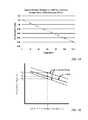
- FIG. 14demonstrates the linear relationship between forward voltage and junction temperature with the forward voltages normalized to ‘1’ at 25° C. (roughly room temperature). As shown in FIG. 14 , the forward voltage developed across the LED junction decreases linearly as the junction temperature increases (and vice versa). As a consequence, LED forward voltages measured at a fixed drive current can be used to provide a fairly precise estimate of junction temperature for a particular LED.
- the magnitude and slope of the line correlating forward voltage to junction temperaturecan vary significantly between LED manufacturers, LED part numbers and even individual LEDs arranged side by side on the same chip.
- the dotted lines shown in FIG. 15show a possible range of forward voltage versus temperature characteristics that may be seen from a particular manufacturer and part number, while the solid line indicates the forward voltage versus temperature line generated by an individual LED from that manufacturer and part number.
- the magnitude of the forward voltagecan vary significantly between individual LEDs at any given temperature.
- FIG. 15shows that the slope of the line relating forward voltage to temperature can vary between individual LEDs. While the differences in slope are typically small, they can represent a few degrees C. measurement error over the operating temperature range of an LED. These measurement errors result in inaccurate temperature compensation if steps are not taken to account for these variations when calibrating conventional LED devices.
- FIGS. 16 and 17illustrate the relative change in luminous flux over junction temperature produced by differently colored LEDs supplied with fixed drive currents.
- the luminous flux produced by green, blue and white LEDschanges relatively little and linearly with changes in junction temperature.
- FIG. 17shows that the luminous flux produced by red, red-orange and, especially, yellow (amber) LEDs changes significantly and sometimes dramatically over temperature, and that these changes are substantially non-linear.
- the drive currents supplied to each color of LEDmust be individually calibrated and adjusted during use of the device.
- Conventional multi-color LED devicesfail to provide calibration and compensation for each color of LED used in the device, and thus, fail to provide accurate temperature compensation in a multi-color LED device.
- FIGS. 18 and 19illustrate typical relationships between luminous flux and LED drive current for different colors of LEDs (e.g., red, red-orange, white, blue and green LEDs). As shown in FIGS. 18 and 19 , the relationship between luminous flux and LED drive current is non-linear for all colors of LEDs, and this non-linear relationship is substantially more pronounced for certain colors of LEDs (e.g., green LEDs). Without accounting for such non-linear behavior, conventional LED devices cannot be used to provide accurate temperature compensation for all LEDs included within the LED device.
- colors of LEDse.g., red, red-orange, white, blue and green LEDs.
- PWM dimmingIn addition to failing to account for non-linear behavior and differences in output characteristics between individual LEDs, conventional LED devices typically use pulse width modulation (PWM) dimming to control the overall luminance of the LED device.
- PWM dimmingthe duty cycle of the drive current (i.e., the ratio of time the drive current is “on”) is adjusted to control the overall luminance of the LED device.
- PWM dimmingcan be undesirable for a number of reasons.
- pulse width modulation at certain frequencieshas been shown to induce seizures and eye strain in some people.
- PWM dimmingcauses issues for the power supply and the LEDs when switching large amounts of currents on and off.
- a larger output capacitormay need to be coupled across the power supply, which adds cost and consumes board space.
- thisdoes not address the transients that occur in the drive currents supplied to the LEDs whenever the drive currents are turned on and off. In some cases, these transients can be visible in the form of flicker or color shift.
- the calibration and compensation methods described hereintake into account and adjust for variations in forward voltage magnitude and slope between individual LEDs, the non-linear relationship between luminous flux and junction temperature for certain colors of LEDs, and the non-linear relationship between luminous flux and drive current for all colors of LEDs. This enables the present invention to provide a more highly precise method of temperature compensation. Further, accurate temperature compensation is provided herein without producing undesirable visual artifacts, such as brightness banding, flicker and color shift.
- a methodfor controlling an illumination device comprising a plurality of light emitting diodes (LEDs) or chains of LEDs, and more specifically, for compensating individual LEDs in the illumination device, so as to maintain a desired luminous flux and/or a desired color point of the device over variations in temperature and process while avoiding flicker in the LED output.
- LEDlight emitting diodes
- the term “LED”will be used herein to refer to a single LED or a chain of serially connected LEDs supplied with the same drive current.
- the compensation method described hereinmay begin by driving the plurality of LEDs substantially continuously with drive currents configured to produce illumination, and periodically turning the plurality of LEDs off for short durations of time during a first period to take measurements or communicate optical data.
- the compensation method described hereinmay increase the drive currents supplied to the plurality of LEDs by a small amount when the LEDs are on during the first period to compensate for lack of illumination when the LEDs are periodically turned off during the first period.
- the small amountmay be approximately 1% to approximately 10% of the drive currents supplied to the LEDs to produce illumination.
- the step of periodically turning the plurality of LEDs off for the short durations of timemay include periodically turning the plurality of LEDs off in synchronization with an AC mains frequency to generate a plurality of time slots in the first period.
- the time slotsmay be used in a variety of different ways.
- the compensation method described hereinmay include measuring an output characteristic (e.g., forward voltage, luminous flux or chromacity) of each LED, one LED at a time, during the time slots.
- one or more of the plurality of LEDsmay be configured for measuring ambient light during the time slots.
- one or more of the plurality of LEDsmay be configured for communicating optical data during the time slots.
- an illumination deviceis provided herein with a plurality of light emitting diode (LED) chains, a driver circuit, a storage medium and a control circuit.
- each LED chainmay be configured for producing illumination at the same peak wavelength, or one or more different peak wavelengths.
- each LED chainmay be configured for producing light of the same color, or one or more different colors.
- the driver circuitmay be generally configured for driving the plurality of LED chains with drive currents substantially continuously to produce illumination, and periodically turning the plurality of LED chains off for short durations of time during a first period to take measurements or communicate optical data.
- the driver circuitmay be configured for supplying a small drive current to each LED chain, one chain at a time, during the short durations of time so that an operating forward voltage developed across each LED chain can be measured.
- the illumination devicemay further include a phase locked loop (PLL) coupled for supplying a timing signal to the driver circuit for periodically turning the plurality of LED chains off for the short durations of time during the first period.
- PLLphase locked loop
- the PLLmay be coupled to an AC mains and may be configured for producing the timing signal in synchronization with a frequency of the AC mains.
- the control circuitmay be generally configured for controlling the drive currents supplied to each LED chain.
- the control circuitmay instruct the driver circuit to increase the drive currents supplied to the plurality of LED chains by a small amount when the LED chains are on during the first period to compensate for lack of illumination when the LED chains are periodically turned off during the first period.
- the small amountmay be approximately 1% to approximately 10% of the drive currents supplied to the plurality of LED chains to produce illumination substantially continuously.
- the storage mediummay be generally configured for storing a table of calibration values correlating forward voltage and drive current to luminous flux at a plurality of temperatures for each of the plurality of LED chains.
- the table of calibration valuesmay include, for each LED chain, a first forward voltage value measured across the LED chain using a small drive current when the LED chain was previously subjected to a first temperature, and a second forward voltage value measured across the LED chain using the small drive current when the LED chain was previously subjected to a second temperature.
- the small drive currentmay range between approximately 0.1 mA and approximately 10 mA, depending on the type and size of LED.
- the table of calibration valuesmay also include, for each LED chain, a first plurality of luminous flux values detected from the LED chain using a plurality of different drive currents when the LED chain was previously subjected to the first temperature, and a second plurality of luminous flux values detected from the LED chain using the plurality of different drive currents when the LED chain was previously subjected to the second temperature.
- the control circuitmay be further configured for determining respective drive currents needed to achieve a desired luminous flux from each LED chain using the operating forward voltages measured across each LED chain during the first period, the table of calibration values and one or more interpolation techniques. For example, the control circuit may be configured to calculate a third plurality of luminous flux values corresponding to the operating forward voltage measured across a given LED chain by interpolating between the first plurality of luminous flux values and the second plurality of luminous flux values stored within the table of calibration values. In one embodiment, the control circuit may be configured to calculate the third plurality of luminous flux values using a linear interpolation technique or a non-linear interpolation technique to interpolate between the first and second plurality of luminous flux values. The selection between the linear interpolation technique and the non-linear interpolation technique is generally made based on a color of the LED being compensated.
- a linear interpolation techniquemay be used for blue, green and white LEDs, which exhibit a substantially linear luminous flux vs. junction temperature (or forward voltage) relationship over the operating temperature range. Because of this linear relationship, the control circuit is able to calculate a third plurality of luminous flux values at the present operating temperature for blue, green and white LEDs by linearly interpolating between the first and second plurality of luminous flux calibration values stored at each drive current.
- red, red-orange and yellow LEDsexhibit a substantially non-linear relationship between luminous flux vs. junction temperature.
- a non-linear interpolation techniquemay be used to determine the third plurality of luminous flux values at the present operating temperature for each drive current.
- the non-linear interpolation techniquemay be a higher-order interpolation, such as a quadratic interpolation.
- the control circuitmay generate a relationship between the third plurality of luminous flux values, if the desired luminous flux differs from one of the third plurality of luminous flux values.
- the control circuitmay be configured to generate the relationship by applying a higher-order interpolation to the third plurality of luminous flux values to generate a non-linear relationship between luminous flux and drive current for the LED chain.
- the control circuitmay be configured to generate the relationship by applying a piece-wise linear interpolation to the third plurality of luminous flux values to approximate a non-linear relationship between luminous flux and drive current.
- the control circuitmay be configured to generate the relationship by assuming a typical curvature from data sheets provided by a manufacturer of the LED chain.
- control circuitmay determine a drive current needed to achieve a desired luminous flux from the given LED chain by selecting, from the generated relationship, a drive current corresponding to the desired luminous flux. However, if the desired luminous flux corresponds to one of the third plurality of luminous flux values, the drive current may be determined without the need to generate the relationship between the third plurality of luminous flux values.
- FIG. 1is a flowchart diagram of an improved method for calibrating an illumination device comprising a plurality of LEDs, in accordance with one embodiment of the invention
- FIG. 2is a graph illustrating exemplary forward voltage values measured from a given LED at two different temperatures during the calibration method of FIG. 1 and the linear relationship between forward voltage and temperature;
- FIG. 3is a graph illustrating exemplary luminous flux values measured from a given LED at three different drive currents and two different temperatures during the calibration method of FIG. 1 , and the substantially non-linear relationship between luminous flux and drive current;
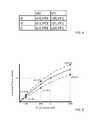
- FIG. 4is a chart illustrating an exemplary table of calibration values that may be obtained in accordance with the calibration method of FIG. 1 and stored within the illumination device;
- FIG. 5is a flowchart diagram of an improved compensation method, in accordance with one embodiment of the invention.
- FIG. 6is a graphical representation depicting how interpolation technique(s) may be used in the compensation method of FIG. 5 to determine the drive current needed to produce a desired luminous flux for a given LED using the calibration values obtained during the calibration phase and stored within the illumination device;
- FIG. 7is a timing diagram for an illumination device comprising four LEDs and illustrates how, in one embodiment of the compensation method shown in FIG. 5 , the LEDs are driven substantially continuously to produce illumination, and the forward voltages developed across the LEDs are repeatedly measured, one LED at a time, during times when the plurality of LEDs are turned off;
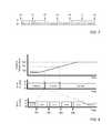
- FIG. 8is a graphical representation of an alternative embodiment of the compensation method shown in FIG. 5 , in which forward voltages are only measured upon detecting a significant change in ambient temperature to avoid brightness banding, and drive currents are increased during the compensation period to avoid flicker;
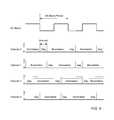
- FIG. 9an exemplary timing diagram for communicating optical data between illumination devices without producing flicker
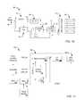
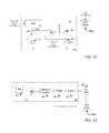
- FIG. 10is an exemplary block diagram of an illumination device, according to one embodiment of the invention.
- FIG. 11is an exemplary block diagram of an LED driver circuit included within the illumination device of FIG. 10 , according to one embodiment of the invention.
- FIG. 12is an exemplary block diagram of a current source included within the driver circuit of FIG. 11 , according to one embodiment of the invention.
- FIG. 13is an exemplary block diagram of a buck converter included within the driver circuit of FIG. 11 , according to one embodiment of the invention.
- FIG. 14is a graph illustrating typical forward voltage vs. LED die junction temperature (normalized to 25° C.);
- FIG. 15is a graph illustrating how the magnitude and slope of the line correlating forward voltage to junction temperature can vary significantly between LED manufacturers, LED part numbers and even individual LEDs arranged side by side on the same chip;
- FIG. 16is a graph illustrating the non-linear relationship between relative luminous flux and junction temperature for white, blue and green LEDs
- FIG. 17is a graph illustrating the substantially more non-linear relationship between relative luminous flux and junction temperature for red, red-orange and yellow (amber) LEDs;
- FIG. 18is a graph illustrating the non-linear relationship between relative luminous flux and forward current for red and red-orange LEDs
- FIG. 19is a graph illustrating the substantially more non-linear relationship between relative luminous flux and forward current for white, blue and green LEDs
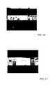
- FIG. 20is a photograph of a display backlit with an array of LEDs and illustrates what the human eye sees during operation of the display.
- FIG. 21is a photograph of the same display taken at a higher shutter speed to illustrate the bright and dark bands that develop across the display screen when LEDs within the array are periodically turned on/off.
- An LEDgenerally comprises a chip of semiconducting material doped with impurities to create a p-n junction.
- currentflows easily from the p-side, or anode, to the n-side, or cathode, but not in the reverse direction.
- Charge-carrierselectrons and holes—flow into the junction from electrodes with different voltages.
- the wavelength of the light emitted by the LEDdepends on the band gap energy of the materials forming the p-n junction of the LED.
- Red and yellow LEDsare commonly composed of materials (e.g., AlInGaP) having a relatively low band gap energy, and thus produce longer wavelengths of light. For example, most red and yellow LEDs have a peak wavelength in the range of approximately 610-650 nm and approximately 580-600 nm, respectively.
- green and blue LEDsare commonly composed of materials (e.g., GaN or InGaN) having a larger band gap energy, and thus, produce shorter wavelengths of light. For example, most green and blue LEDs have a peak wavelength in the range of approximately 515-550 nm and approximately 450-490 nm, respectively.
- differently colored LEDsmay be combined to produce white light within a wide gamut of color points or correlated color temperatures (CCTs) ranging from “warm white” (e.g., roughly 2600K-3700K), to “neutral white” (e.g., 3700K-5000K) to “cool white” (e.g., 5000K-8300K).
- white light illumination devicesinclude, but are not limited to, those that combine red, green and blue (RGB) LEDs, red, green, blue and yellow (RGBY) LEDs, white and red (WR) LEDs, and RGBW LEDs.
- the present inventionis generally directed to illumination devices having a plurality of light emitting diodes (LEDs), and provides improved methods for controlling output characteristics of the LEDs over variations in temperature and process.
- the methods described hereinmay be used to control the luminous flux emitted from a plurality of LEDs, if the LEDs are all of the same color, or may be used to control the luminous flux and color point (or color temperature) of the LEDs, if the illumination device comprises two or more differently colored LEDs.
- the present inventionis particularly well suited to illumination devices in which two or more different colors of LEDs are combined to produce white light or near-white light, since the output characteristics of differently colored LEDs vary differently over temperature.
- the present inventionis also particularly well suited to illumination devices that include LEDs with lower band gap energies, such as red, red-orange and yellow LEDs, as the output characteristics of these LEDs are particularly susceptible to variations in temperature.
- LEDs with lower band gap energiesare more susceptible to variations in temperature than LEDs with larger band gap energies (e.g., white, blue and green).
- the luminous fluxi.e., a perceived power of the emitted light, measured in lumens
- red, red-orange and yellow LEDsdecreases much faster as temperatures increase, than the luminous flux produced by white, blue and green LEDs. This is because there are fewer charge-carriers contributing to light emission in materials having lower band gap energies; thus, LEDs comprised of these materials generate less light (i.e., less luminous flux) when subjected to increasingly higher temperatures.
- the color point of the resulting devicemay change significantly over variations in temperature. For example, when red, green and blue LEDs are combined within a white light illumination device, the color point of the device may appear increasingly “cooler” as the temperature rises. This is because the luminous flux produced by the red LEDs decreases significantly as temperatures increase, while the luminous flux produced by the green and blue LEDs remains relatively stable.
- improved methodsare needed to individually calibrate and compensate each color of LED used in the multi-colored illumination device.
- improved calibration and compensation methodsare needed to overcome the disadvantages of conventional methods, which fail to provide accurate temperature compensation in a multi-colored LED device by failing to account for variations between individual LEDs, non-linear relationships between luminous flux and junction temperature, and non-linear relationships between luminous flux and drive current.
- FIG. 1illustrates one embodiment of an improved method for calibrating an illumination device comprising a plurality of LEDs or chains of LEDs.
- LEDwill be used herein to refer to a single LED or a chain of serially connected LEDs supplied with the same drive current.
- the method shown in FIG. 1may be used to calibrate an illumination device having LEDs all of the same color.
- the methodmay be particularly well-suited for calibrating an illumination device comprising two or more differently colored LEDs, since output characteristics of differently colored LEDs tend to differ from one another.
- the improved calibration methodmay begin by subjecting the illumination device to a first ambient temperature (in step 10 ). Once subjected to this temperature, a forward voltage measurement and a plurality of luminous flux measurements may be obtained from each of the LEDs included within the illumination device. For example, a relatively small drive current (e.g., approximately 0.1-10 mA) may be supplied to each of the LEDs, so that a forward voltage developed across the anode and cathode of the LEDs can be measured (in step 12 ). As used herein, a “relatively small drive current” may be broadly defined as a non-operative drive current, or a drive current level which is insufficient to produce significant illumination from the LED device.
- a relatively small drive currente.g., approximately 0.1-10 mA
- the optimum drive current used to obtain forward voltage measurements in the presently described methodsmay be roughly 0.3-3 mA.
- smaller/larger LEDsmay use proportionally less/more current to keep the current density roughly the same.
- the optimum drive current levelmay fall within a range of approximately 0.1-10 mA.
- Forward voltage measurementsare taken (in step 12 ) by supplying a relatively small drive current to each LED, one LED at a time.
- all other emission LEDs in the illumination deviceare turned off to avoid inaccurate forward voltage measurements (since light from these LEDs would induce additional photocurrents in the LED being measured).
- the emission LEDs not currently under testmay be turned off by cutting off the drive current supplied thereto, or at least reducing the supplied drive currents to a non-operative level.
- the calibration methodmay continue (in step 14 ) by measuring the luminous flux output from each LED at a plurality of different drive current levels. Specifically, two or more different drive current levels may be successively applied to each LED, one LED at a time, and the luminous flux produced by each LED may be detected at each of the different drive current levels.
- the drive currents used to measure luminous fluxmay be operative drive current levels (e.g., about 20 mA to about 500 mA), and thus, may be substantially greater than the relatively small, non-operative drive current (e.g., about 0.3 mA to about 3 mA) used to measure forward voltage.
- luminous fluxmay be detected upon successively applying decreasing levels of drive current to the LEDs.
- the order in which the drive current levels are applied during the luminous flux measurementsis largely unimportant, only that the drive currents be different from one another.
- three luminous flux measurementsmay be obtained from each LED at roughly a maximum drive current level (typically about 500 mA, depending on LED part number and manufacturer), roughly 30% of the maximum drive current, and roughly 10% of the maximum drive current, as shown in FIG. 3 and discussed below.
- the present inventionis not limited to any particular value or any particular number of drive current levels, and may apply substantially any value and any number of drive current levels to an LED within the operating current level range of that LED. However, it is generally desired to obtain the luminous flux measurements at a sufficient number of different drive current levels, so that a luminous flux vs. drive current relationship can be accurately characterized across the operating current level range of the LED during the compensation method of FIG. 4 .
- luminous flux measurementsmay be beneficial when attempting to characterize the luminous flux vs. drive current relationship for certain colors of LEDs. For instance, additional measurements may be beneficial when characterizing the luminous flux vs. drive current relationship for blue and green LEDs, which tend to exhibit a significantly more non-linear relationship (see, FIGS. 17-18 ) than other colors of LEDs. Thus, a balance should be struck between accuracy and calibration time/costs when selecting a desired number of drive current levels with which to obtain luminous flux measurements for a particular color of LED.
- the illumination deviceis subjected to a second ambient temperature, which is substantially different from the first ambient temperature (in step 16 ).
- the calibration methodmay obtain an additional forward voltage measurement (in step 18 ), and in some cases, a plurality of additional luminous flux measurements (in steps 20 and 24 ), from each LED.
- the forward voltage measurement and the plurality of (optional) luminous flux measurementsmay be obtained at the second ambient temperature in the same manner described above for the first ambient temperature.
- the measurement valuesmay be stored (in step 22 ) within the illumination device, so that the stored values can be later used to compensate the illumination device for changes in luminance and/or color point that may occur with variations in temperature and process.
- the luminous flux vs. forward voltage at each drive currentmay be stored within a table of calibration values, as shown for example in FIG. 4 and discussed below.
- the second ambient temperaturemay be substantially less than the first ambient temperature.
- the second ambient temperaturemay be approximately equal to room temperature (e.g., roughly 25° C.), and the first ambient temperature may be substantially greater than room temperature.
- the first ambient temperaturemay be closer to an elevated temperature (e.g., roughly 70° C.) or a maximum temperature (e.g., roughly 85° C.) at which the device is expected to operate.
- the second ambient temperaturemay be substantially greater than the first ambient temperature.
- the exact values, number and order in which the temperatures are applied to calibrate the individual LEDsis somewhat unimportant. However, it is generally desired to obtain the forward voltage and luminous flux measurements at a number of different temperatures, so that the forward voltage vs. junction temperature relationship and the luminous flux vs. drive current relationship can be accurately characterized across the operating temperature range of each LED.
- the illumination devicemay be subjected to two (or more) substantially different ambient temperatures selected from across the operating temperature range of the illumination device.
- the illumination devicemay be subjected to the first and second ambient temperatures by artificially generating the temperatures during the calibration process.
- the first and second ambient temperaturesare ones which occur naturally during production of the illumination device, as this simplifies the calibration process and significantly decreases the costs associated therewith.
- the elevated temperature forward voltage and luminous flux measurementsmay be taken after burn-in of the LEDs when the illumination device is relatively hot (e.g., roughly 50° C. to 85° C.), and sometime thereafter (e.g., at the end of the manufacturing line), a room temperature calibration may be performed to measure the forward voltage and/or the luminous flux output from the LEDs when the illumination device is relatively cool (e.g., roughly 20° C. to 30° C.).
- FIGS. 2 and 3illustrate exemplary forward voltage and luminous flux measurement values that may be obtained from an individual LED by following the calibration method steps shown in FIG. 1 and described above.
- two forward voltage measurements(Vf0, Vf1) are obtained from each LED, one LED at a time, upon subjecting the illumination device to two substantially different temperatures (T0, T1). While it is possible to measure the forward voltage of a given LED at three (or more) temperatures, doing so may add significant expense, complexity and/or time to the calibration process. Furthermore, calibrating the forward voltage measurements at additional temperatures may not significantly improve the accuracy of the calibration results, as the forward voltage vs. temperature relationship is highly linear for all LEDs. For these reasons, it is generally preferred that the forward voltage measurements be calibrated at two different temperatures (e.g., 25° C. and 70° C.) for each LED, so that the forward voltage calibration values can be later used during the compensation method.
- two different temperaturese.g., 25° C. and 70° C.
- luminous flux measurements(L(I0, Vf0), L(I1, Vf0), L(I2, Vf0), L(I0, Vf1), L(I1, Vf1) and L(I2, Vf1)) are obtained for each LED by successively applying three different drive currents (e.g., T0, I1 and I2) to each LED, one LED at a time, upon subjecting the illumination device to two different temperatures (T0, T1). While it is possible to obtain luminous flux measurements at only one temperature, or even at three (or more) temperatures, it is generally preferred that the measurements be obtained at two temperatures, as shown in FIG. 3 . While an exemplary number of drive current levels and values of drive current are shown in FIG.
- the present inventionis not limited to such examples. It is certainly possible to obtain a greater/lesser number of luminous flux measurements from each LED by applying a greater/lesser number of drive current levels to the individual LEDs. It is also possible to use substantially different values of drive current, other than those specifically illustrated in FIG. 3 .
- the number of drive current levels and the particular values of the drive current used to obtain luminous flux measurements from a particular LEDmay be selected based upon the color of the LED being characterized. For example, the luminous flux vs. drive current relationships for some LED colors, such as blue and green, are comparatively more non-linear than other LED colors, such as red and red-orange (see, FIGS. 17-18 ). LED colors exhibiting substantially greater non-linear behaviors (such as blue and green) may be more accurately characterized by obtaining additional luminous flux measurements.
- the forward voltage and luminous flux values measured during steps 12 , 14 , 18 and 24may be stored within the illumination device in step 22 of the calibration method of FIG. 1 .
- the calibration valuesmay be stored within a table of calibration values, as shown for example in FIG. 4 .
- the stored calibration valuesmay then be used in the compensation method of FIG. 5 (discussed below) to adjust or maintain the luminous flux output from each individual LED. If the illumination device comprises multiple colors of LEDs, the stored calibration values may also be used to adjust or maintain the color point of the illumination device.
- FIG. 1An exemplary method for calibrating an illumination device comprising a plurality of LEDs has now been described with reference to FIGS. 1-4 .
- the method steps shown in FIG. 1are described as occurring in a particular order, one or more of the steps of the illustrated method may be performed in a substantially different order.
- the luminous flux output from the LEDsmay be detected at two or more drive currents (e.g., in step 14 ) before the forward voltage is measured (e.g., in step 12 ) from the LEDs.
- the embodiment shown in FIG. 1indicates that forward voltage and luminous flux are measured at possibly two different temperatures, an alternative embodiment of the illustrated method may obtain such measurements at only one temperature, or more than two temperatures.
- the illustrated methodillustrates the forward voltage and luminous flux measurements as being stored at the end of the calibration method (e.g., in step 22 ), a skilled artisan would recognize that these values may be stored at substantially any time during the calibration process without departing from the scope of the invention.
- the calibration method described hereinis considered to encompass all such variations and alternative embodiments.
- the calibration method provided hereinimproves upon conventional calibration methods in a number of ways.
- the method described hereincalibrates each LED (or chain of LEDs) individually, while turning off all emission LEDs not currently under test. This not only improves the accuracy of the forward voltage and luminous flux calibration values, but also enables the stored calibration values to account for process variations between individual LEDs, as well as differences in output characteristics that inherently occur between different colors of LEDs.
- Accuracyis further improved herein by supplying a relatively small (i.e., non-operative) drive current to the LEDs when obtaining forward voltage measurements, as opposed to the operative drive current levels used in conventional calibration methods.
- non-operative drive currentsto obtain the forward voltage calibration values, and again later to take forward voltage measurements during the compensation method, the present invention avoids inaccurate compensation by ensuring that the forward voltage measurements for a given temperature and fixed drive current do not change significantly over time (due to parasitic resistances in the junction when operative drive currents are used to obtain forward voltage measurements).
- the calibration method described hereinobtains a plurality of luminous flux measurements for each LED at a plurality of different drive current levels. This further improves calibration accuracy by enabling the non-linear relationship between luminous flux and drive current to be precisely characterized for each individual LED. Furthermore, obtaining forward voltage and luminous flux calibration values at a number of different temperatures improves compensation accuracy by enabling the compensation method (described below) to interpolate between the stored calibration values, so that accurate compensation values may be determined for current operating temperatures.
- FIGS. 5-8illustrate exemplary embodiments of an improved method for controlling an illumination device comprising a plurality of LEDs, and more specifically, for compensating individual LEDs of the illumination device to accurately account for variations in temperature and process.
- the compensation method shown in FIG. 5may begin by driving the plurality of LEDs substantially continuously to produce illumination (in step 30 ).
- substantially continuouslymeans that an operative drive current is supplied to the plurality of LEDs almost continuously, with the exception of periodic intervals during which the plurality of LEDs are momentarily turned off for short durations of time (in step 32 ). These periodic intervals may be utilized for obtaining operating forward voltage measurements during a compensation period (in step 34 ), as shown in the embodiments of FIGS. 5 and 7-8 . These periodic intervals may also be used for other purposes, as shown in FIG. 9 and described below.
- FIG. 7is an exemplary timing diagram illustrating steps 30 , 32 and 34 of the compensation method shown in FIG. 5 , according to one embodiment of the invention.
- the plurality of LEDSare driven substantially continuously with operative drive current levels (denoted generically as I1 in FIG. 7 ) to produce illumination (in step 30 of FIG. 5 ).
- the plurality of LEDsare turned off for short durations of time (in step 32 of FIG. 5 ) by removing the drive currents, or at least reducing the drive currents to non-operative levels (denoted generically as I0 in FIG. 7 ).
- one LEDis driven with a relatively small, non-operative drive current (e.g., approximately 0.1-10 mA, not shown in FIG. 7 ) and the operating forward voltage developed across that LED is measured (e.g., Vf1, Vf2, Vf3 or Vf4).
- the forward voltageis measured across each LED, one LED at a time, and then the process repeats in the embodiment shown in FIG. 7 .
- the illumination deviceproduces continuous illumination with DC current supplied to the LEDs.
- FIG. 7provides an exemplary timing diagram for measuring the forward voltage developed across each LED in an illumination device comprising four LEDs, such as RGBY or RGBW. Although four LEDs are used in the embodiment of FIG. 7 , the timing diagram and method described herein can easily be modified to accommodate a fewer or greater number of LEDs.
- the compensation method shown in FIG. 5determines the drive current (Ix) needed to achieve a desired luminous flux (Lx) from each LED using the operating forward voltages, the table of stored calibration values generated during the calibration method of FIG. 1 and one or more interpolation techniques (in step 36 of FIG. 5 ). For example, the compensation method may calculate a luminous flux value for the present forward voltage/operating temperature at each of the previously calibrated drive current levels by interpolating between the stored calibration values.
- a luminous flux valueis calculated at each of the previously calibrated (i.e., known) drive current levels
- another interpolation techniquemay be used to determine an unknown drive current needed to produce a desired luminous flux, should the desired luminous flux differ from one of the calculated luminous flux values.
- FIG. 6is a graphical illustration depicting how one or more interpolation technique(s) may be used to determine the drive current needed to produce a desired luminous flux from the stored calibration values.
- the six solid dotsrepresent the luminous flux calibration values, which were obtained during the calibration phase at three different drive currents (I0, I1, and I2) and two different temperatures (T0 and T1) for each LED and stored within the table of calibration values shown, e.g., in FIG. 4 .
- the luminous flux calibration valuessolid dots
- the three X'srepresent luminous flux values, which are calculated during the compensation method at the same three drive currents (10%, 30% and 100% of the maximum drive current) for the present operating temperature (Tx).
- the value at each Xis calculated, in one example, by interpolating between the stored calibration values. However, the exact interpolation technique used to determine the luminous flux value at each X may generally depend on the color of the LED being compensated.
- the luminous flux vs. junction temperature (or forward voltage) relationship for blue, green and white LEDsis substantially linear over the operating temperature range (see, FIG. 16 ). Because of this linear relationship, the compensation method is able to calculate luminous flux values at the present Vf (e.g., X values in FIG. 6 ) for blue, green and white LEDs by linearly interpolating between the calibration values stored at each drive current. However, red, red-orange and yellow LEDs exhibit a substantially non-linear relationship between luminous flux vs. junction temperature (see, FIG. 17 ). For these LEDs, a higher-order interpolation technique may be used to determine the luminous flux values at the present Vf (e.g., X values in FIG. 6 ) for each drive current.
- Vfe.g., X values in FIG. 6
- the ‘a’ coefficientmay be obtained from data sheets provided by the LED manufacturer, while the ‘b’ and ‘c’ coefficients are determined from the calibration values, as described above. While the latter method (sometimes referred to as a “poor man's quadratic interpolation”) may sacrifice a small amount of accuracy, it may in some cases represent an acceptable trade-off between accuracy and calibration costs.
- a relationship (solid black line in FIG. 6 ) between the luminous flux values calculated at the three X'smay be determined through another interpolation technique, if a desired luminous flux (Lx) differs from one of the calculated values.
- Lxdesired luminous flux
- the relationshipmay be derived, in some embodiments, through a higher-order interpolation of the calculated luminous flux values.
- a piece-wise linear interpolationcould be used to characterize the non-linear relationship between the calculated luminous flux values, or a typical curvature could be assumed from data sheets provided by the LED manufacturer.
- an appropriate interpolation techniquemay be selected based on trade-offs between memory and processing requirements, and/or based upon the particular color of LED being compensated.
- some LED colorssuch as blue and green, exhibit a comparatively more non-linear luminous flux vs. drive current relationship than other LED colors, such as red and red-orange (see, FIGS. 18-19 ).
- LED colors exhibiting substantially greater non-linear behaviorsmay be more accurately compensated by obtaining more luminous flux calibration values and using a piece-wise linear interpolation technique, or by obtaining fewer calibration values and using a higher-order interpolation technique or an assumed curvature to generate the non-linear relationship between luminous flux and drive current.
- the drive current (Ix) needed to produce a desired luminous flux (Lx)may be selected from the generated relationship, as shown in the example of FIG. 6 .
- the selected drive currentmay then be used to drive the LED to produce illumination having the desired luminous flux (in step 38 of FIG. 5 ).
- This processis then repeated for each of the plurality of LEDs, until each is configured for producing a desired luminous flux at the present operating temperature.
- the drive currents supplied to the LEDsmay be adjusted to meet the selected drive currents either by adjusting the drive current level (i.e., current dimming), or by changing the duty cycle of the drive current through Pulse Width Modulation (PWM) dimming.
- PWMPulse Width Modulation
- the compensation method shown in FIG. 5provides many advantages over conventional compensation methods.
- the present compensation methoduses a relatively small drive current to obtain operating forward voltage measurements from each LED individually, while turning off all emission LEDs not currently under test. This improves the accuracy of the operating forward voltage values and enables each LED to be individually compensated for temperature and process.
- the compensation method described hereinderives a non-linear relationship between luminous flux and drive current for each LED at the present operating temperature (or Vf) using the stored calibration values taken at the different temperatures during the calibration process. This enables the present compensation method to precisely characterize the luminous flux vs.
- the compensation method described hereinis able to more precisely control the luminous flux (if the LEDs are all of the same color), or the luminous flux and color point (if the illumination device comprises two or more differently colored LEDs).
- a further advantage of the present compensation methodis the ability to provide accurate temperature compensation while avoiding undesirable visible artifacts in the generated light.
- One undesirable artifactcalled “brightness banding,” often occurs whenever LEDs are periodically turned on and off for any reason, even at imperceptibly high rates.
- This banding artifactis demonstrated in the photograph of FIG. 21 and described above as alternating bands of light and dark areas on a display screen backlit by an array of LEDs. The bright and dark bands that develop across the display screen may occur whenever light emitted by the LEDs is modulated or turned on/off for any reason, such as when obtaining forward voltage measurements for temperature compensation or when modulating light output to communicate optical data in visible light communication (VLC) systems.
- VLCvisible light communication
- Another visual artifactmay occur during times when the LEDs are periodically turned off to measure forward voltage or communicate optical data.
- flickermay occur during times when the LEDs are periodically turned off to measure forward voltage or communicate optical data.
- the amount of light produced by the illumination devicedecreases, and when the LEDs are turned back on, the amount of light produced by the illumination device increases. This phenomenon may cause the illumination device to appear to flicker in either brightness and/or color.
- FIGS. 5 and 8A solution for avoiding flicker in a VLC system is illustrated in FIG. 9 .
- the compensation method described hereinmay achieve a desired luminous flux and/or color point from an illumination device, while avoiding undesirable visual artifacts, such as brightness banding and flicker. Such embodiments are illustrated in the optional method steps of FIG. 5 and the timing diagrams of FIG. 8 .
- the ambient temperature (Ta) surrounding an illumination deviceincreases steadily over time during operation of the device, until the temperature stabilizes (e.g., at Ta 2 ). Since it is only necessary to perform the compensation method while the ambient temperature changes, alternative embodiments of the compensation method described herein may determine if there has been a significant change in ambient temperature (in optional step 31 of FIG. 5 ) before proceeding with steps 32 - 38 .
- a “significant change”may be any incremental increase or decrease in ambient temperature. For example, a “significant change” may be a 1° C. increase or decrease in temperature. Other temperature increments may be used in other examples.
- the plurality of LEDsare turned off for short durations of time (in step 32 of FIG. 5 ), and the LED forward voltages (e.g., Vf1, Vf2, Vf3, and Vf4 of FIG. 8 ) are measured using a relatively small drive current (in step 34 of FIG. 5 ). New LED drive currents are calculated and applied to compensate for the change in temperature (in steps 36 - 38 of FIG. 5 ). However, once the ambient temperature stabilizes (“No” branch of step 31 of FIG. 5 ; Ta 2 in the uppermost graph of FIG. 8 ), forward voltage measurements are no longer needed and the LEDs are driven to produce continuous illumination so that brightness banding does not occur.
- the ambient temperaturestabilizes (“No” branch of step 31 of FIG. 5 ; Ta 2 in the uppermost graph of FIG. 8 )
- FIG. 8provides a solution for avoiding flicker during the times when the LEDs are periodically turned off to measure forward voltage.
- forward voltageis measured from a given LED
- all other emission LEDsare turned off to avoid inducing photocurrents within the LED under test.
- the illumination devicemay appear to flicker in brightness and/or color.
- the flicker phenomenonis avoided in the present compensation method by increasing the drive currents supplied to the LEDs by a small amount when the LEDs are turned on during the compensation period (in optional step 35 of FIG. 5 ). This is illustrated graphically in the two lowermost graphs of FIG. 8 .
- the LEDsare driven with a first drive current level (denoted generically as I1) to produce continuous illumination.
- I1a first drive current level
- the LEDsare momentarily and periodically turned off to take forward voltage measurements (e.g., Vf1, Vf2, Vf3, and Vf4) from each LED, one LED at a time.
- the drive currents supplied to the plurality of LEDsare increased or boosted to a second drive current level (denoted generically as I2).
- flickermay be avoided by increasing the drive current level by approximately 1-10% during the compensation period, such that I2 is substantially 1-10% greater than I1.
- the duty cycle of the drive currentmay also be increased by approximately 1-10% during the compensation period to avoid flicker.
- Brightness banding and flickermay also occur whenever light emitted by the LEDs is modulated to communicate optical data in visible light communication (VLC) systems.
- VLCvisible light communication
- LEDsare used for producing illumination, transmitting and receiving optical data, detecting ambient light and measuring output characteristics of other LEDs. Synchronized timing signals are supplied to the LEDs to produce time division multiplexed communication channels in which data is communicated optically by the same LEDs that produce illumination.
- the timing signalsare synchronized in frequency and phase to a common source, preferentially to the AC mains, so that the LEDs within the illumination devices can be periodically turned off in synchronization with the AC mains to produce a plurality of time slots in a first communication channel for communicating optical data. Additional communication channels may be generated when additional timing signals are synchronized to the same frequency, but different phase, used to produce the first communication channel. During these time slots, data may be communicated optically between illumination devices when one device produces light modulated with data, while the LEDs of other illumination devices are configured to detect and receive the optically communicated data. In addition to communicating optical data, the time slots may be used for other purposes. For example, one or more of the LEDs can be configured to measure ambient light or an output characteristic (e.g., forward voltage, luminous flux or chromacity) from other LEDs in the illumination device during the time slots.
- an output characteristice.g., forward voltage, luminous flux or chromacity
- Brightness banding and flickeroccur in VLC systems, such as the one described in U.S. Publication No. 2011/0069960, whenever the LEDs of an illumination device are periodically turned off to receive data, measure ambient light or measure output characteristics from other LEDs during the time slots.
- brightness bandingmay be reduced by limiting VLC communications to short period(s) of time. For example, VLC may only occur periodically, only when initiated manually by a user or automatically by a controlling system, or only at designated times, such as during start-up when the illumination device is initially turned on. In other cases, brightness banding may be reduced by restricting the use of VLC to certain applications.
- VLCmay be limited to commissioning a set of illumination devices (e.g., establishing groupings of devices, setting addresses and output characteristics of the devices, etc.) included in a lighting system.
- a solution for avoiding the flicker phenomenon in a VLC systemis illustrated in FIG. 9 .
- FIG. 9is an exemplary timing diagram for communicating optical data between illumination devices without producing flicker.
- FIG. 9illustrates a relationship between the AC mains timing (typically 50 or 60 Hz) and four different communication channels labeled Channel 0 through Channel 3.
- the communication channelsare generated by driving a plurality of LEDs substantially continuously with drive currents configured to produce illumination, and periodically turning the plurality of LEDs off for short durations of time to produce gaps within the illumination, or time slots, within which data can be communicated optically or measurements can be taken.
- Channels 0 through 3provide a plurality of communication gaps or time slots having different non-overlapping phases relative to the AC mains timing.
- the four communication channelscomprise alternating illumination and gap times.
- illumination timeslight from an illumination device may be on continually to produce a maximum brightness, or Pulse Width Modulated (PWM) to produce less brightness.
- PWMPulse Width Modulated
- datacan be sent from one device to any or all other devices, or measurements can be taken.
- the time slot durationis one quarter of the AC mains period, which enables four data bytes to be communicated at an instantaneous bit rate of 60 Hz ⁇ 4 ⁇ 32, or 7.68K bits per second, with an average bit rate of 1.92K bits per second for each channel.
- the drive currents supplied to the plurality of LEDsmay be increased by a small amount (e.g., about 1-10%) when the LEDs are turned on for producing illumination, thereby compensating for the lack of illumination when the LEDs are periodically turned off to receive optical data or take measurements. This is illustrated in FIG. 9 by increasing the current level from I1 to I2 over the entire illumination period between each of the gap times. If PWM dimming is used (not shown) instead of current dimming, the duty cycle of the drive current supplied to each of the LEDs during the illumination periods may be increased by about 1-10% to avoid flicker.
- each LEDmay be driven with a drive current needed to produce a desired luminous flux from that LED, regardless of process and temperature variations.
- the individual drive currents needed to drive each LEDmay be determined and applied according to the method steps shown in FIG. 5 , and may be increased by approximately 1-10% during the illumination periods shown in FIG. 9 to avoid flicker during times of VLC communications.
- FIG. 10is one example of a block diagram of an illumination device 40 , which is configured to accurately maintain a desired luminous flux and/or a desired color point over variations in temperature and process.
- the illumination device illustrated in FIG. 10provides one example of the hardware and/or software that may be used to implement the calibration and compensation methods shown respectively in FIGS. 1 and 5 .
- illumination device 40is connected to AC mains 42 and comprises an AC/DC converter 44 , a DC/DC converter 46 , a phase locked loop (PLL) 48 , a wireless interface 50 , a control circuit 52 , a driver circuit 54 and a plurality of LEDs 56 .
- the LEDs 56in this example, comprise four chains of any number of LEDs. In typical embodiments, each chain may have 2 to 4 LEDs of the same color, which are coupled in series and receive the same drive current.
- the LEDs 56may include a chain of red LEDs, a chain of green LEDs, a chain of blue LEDs, and a chain of yellow LEDs.
- the present inventionis noted limited to any particular number of LED chains, any particular number of LEDs within the chains, or any particular color or combination of LED colors. However, the present invention may be particularly well suited when one or more different colors of LEDs are included within the illumination device 40 .
- the AC/DC converter 44converts AC mains power (e.g., 120V or 240V) to a DC voltage (labeled V DC in FIG. 10 ), which is supplied to the driver circuit 54 for producing the respective drive currents for LEDs 56 .
- the DC/DC converter 46converts the DC voltage V DC (e.g., 15V) to a lower voltage V L (e.g., 3.3V), which may be used to power the low voltage circuitry included within the illumination device, such as PLL 48 , wireless interface 50 , and control circuit 52 .
- the PLL 48locks to the AC mains frequency (50 or 60 HZ) and produces a high speed clock (CLK) signal and a synchronization signal (SYNC).
- CLKhigh speed clock
- SYNCsynchronization signal
- the CLK signalprovides the timing for the control circuit 52 and the driver circuit 54 .
- the CLK signalis in the tens of mHz range (e.g., 23 MHz), and is precisely synchronized to the AC Mains frequency and phase.
- the SNYC signalis used by the control circuit 52 to create the timing used to obtain the forward voltage measurements.
- the SNYC signal frequencyis equal to the AC Mains frequency (e.g., 50 or 60 HZ) and also has a precise phase alignment with the AC Mains.
- the wireless interface 50may be used to calibrate the illumination device 40 during manufacturing.
- an external production calibration tool(not shown) could communicate luminous flux measurements and other information to a device under test via the wireless interface 50 .
- the calibration valuesmay then be stored within a storage medium of the control circuit 52 , for example.
- the wireless interface 50is not limited to receiving only calibration data, and may be used for communicating information and commands for many other purposes.
- the wireless interface 50could be used during normal operation to communicate commands used to control the illumination device 40 or to obtain information about the illumination device.
- commandsmay be communicated to the illumination device 40 via the wireless interface 50 to turn the illumination device on/off, to control the dimming and/or color of the illumination device, to initiate forward voltage measurements, or to store measurement results in memory.
- the wireless interface 50may be used to obtain status information or fault condition codes associated with the illumination device 40 .
- the wireless interface 50could operate according to ZigBee, WiFi, Bluetooth, or any other proprietary or standard wireless data communication protocol. In other embodiments, the wireless interface 50 could communicate using radio frequency (RF), infrared (IR) light or visible light. In alternative embodiments, a wired interface could be used, in place of the wireless interface 50 shown, to communicate information, data and/or commands over the AC mains or a dedicated conductor or set of conductors.
- RFradio frequency
- IRinfrared
- a wired interfacecould be used, in place of the wireless interface 50 shown, to communicate information, data and/or commands over the AC mains or a dedicated conductor or set of conductors.
- the control circuit 52uses the timing signals received from the PLL 48 to calculate and produces values indicating the desired drive current to be used for each LED chain 56 .
- This informationmay be communicated from the control circuit 52 to the driver circuit 54 over a serial bus conforming to a standard, such as SPI or I2C, for example.
- the control circuit 52may provide a latching signal that instructs the driver circuit 54 to simultaneously change the drive currents supplied to each of the LED 56 to prevent brightness and color artifacts.
- the control circuit 52may include a storage medium (e.g., non-volatile memory) for storing a table of calibration values correlating forward voltage and drive current to luminous flux at a plurality of different temperatures for each of the LEDs 56 .
- the control circuit 52may be configured for determining respective drive currents needed to achieve a desired luminous flux from each LED in accordance with the compensation method shown in FIG. 5 and described above.
- the control circuit 52may determine the respective drive currents by executing program instructions stored within the storage medium.
- the control circuit 52may include combinatorial logic for determining the desired drive currents.
- the LED driver circuit 54may include a number of driver blocks equal to the number of LED chains 56 included within the illumination device.
- LED driver circuit 54comprises four driver blocks, each configured to produce illumination from a different one of the LEDs chains 56 .
- the LED driver circuit 54also comprises the circuitry needed to measure ambient temperature (optional) and forward voltage, and to adjust LED drive currents accordingly.
- Each driver blockreceives data indicating a desired drive current from the control circuit 52 , along with a latching signal indicating when the driver block should change the drive current.
- FIG. 11is an exemplary block diagram of an LED driver circuit 54 , according to one embodiment of the invention.
- the driver circuit 54includes four driver blocks, each block 58 including a buck converter 60 , a current source 62 , a difference amplifier 64 , and an LC filter 66 for producing illumination and taking forward voltage measurements from a connected LED chain 56 a .
- the LED driver circuit 54includes an analog to digital converter (ADC) 68 for digitizing the output of the difference amplifiers 64 included within each driver block 58 , and controller 70 for the control circuit 52 to use to adjust the current produced by the current source 62 .
- ADCanalog to digital converter
- the LED driver circuit 54may include an optional temperature sensor 72 for taking ambient temperature (Ta) measurements, and a multiplexor (mux) 74 for multiplexing the ambient temperature (Ta) and forward voltage (Vf) measurements sent to the ADC 68 .
- the temperature sensor 72may be a thermistor, and may be included on the driver circuit chip for measuring the ambient temperature surrounding the LEDs, or a temperature from a heat sink coupled to the LEDs.
- the temperature sensor 72may be an LED, which is used as both a temperature sensor and an optical sensor to measure ambient light conditions or output characteristics of the LED chains 56 .
- the buck converter 60may produce a pulse width modulated (PWM) voltage output (Vdr) when the controller 70 drives the “Out_En” signal high.
- PWMpulse width modulated
- This voltage signal (Vdr)is filtered by the LC filter 66 to produce a forward voltage on the anode of the connected LED chain 56 a .
- the cathode of the LED chainis connected to the current source 62 , which forces a fixed drive current equal to the value provided by the “Current” signal through the LED chain 56 a when the “Led_On” signal is high.
- the Vc signal from the current source 62provides feedback to the buck converter 60 to output the proper duty cycle and minimize the voltage drop across the current source 62 .
- the difference amplifier 64produces a signal relative to ground that is equal to the forward voltage (Vf) drop across the LED chain 56 a during forward voltage measurements.
- the ADC 68digitizes the forward voltage (Vf) output from the difference amplifier 64 and provides the result to the controller 70 .
- the controller 70determines when to take forward voltage measurements and produces the Out_En, Current, and Led_On signals.
- the forward voltage (Vf) output from the difference amplifier 64may be multiplexed with the ambient temperature (Ta) output from the temperature sensor 72 and connected to the ADC 68 .
- the ADC 68digitizes the temperature sensor and difference amplifier outputs and provides the results to the controller 70 .
- the controller 70determines when to take the temperature and forward voltage measurements and produces the Out_En, Current, and Led_On signals.
- FIG. 12is an exemplary block diagram of the current source 62 shown in FIG. 11 , according to one embodiment of the invention.
- the current source 62includes a current digital to analog converter (DAC) 72 that is connected to ground through an N-channel Field Effect Transistor (NFET) 74 , an error amplifier 76 , and stack of two NFETs 78 and 80 , which are connected to the cathode of the LED chain 56 a .
- the DACis coupled for receiving the “Current” signal from the controller 70 and for producing a reference current (Iref).
- the NFET 74 coupled to the DACoperates as a resistor to generate a reference voltage (Vref) for the error amplifier 76 .
- the gate of the top NFET 78provides the Vc signal, which is input to the buck converter 60 to adjust the voltage on the LED chain anode to a minimum needed by the current source 62 .
- the error amplifier 76adjusts the gate of the top NFET 78 until the drain voltage of the bottom NFET 80 is the same as the reference voltage (Vref).
- the impedance of the bottom NFET 80is precisely 1/1000th that of NFET 74 when the “Led_On” signal is high. This forces the drive current (Idr) through the LED chain 56 a to be precisely 1000 times the value of the reference current (Iref) generated by the current DAC 72 .
- the value of the drive currentis adjusted through the “Current” signal provided by the controller 70 .
- the reference current (Iref) generated by the DAC 72may range from about 0.1 uA to about 1 mA, so that the LED drive current (Idr) can range between about 1 mA to about 1 A.
- a 0.1 mA-10 mA drive current settingis preferably used during forward voltage measurements, while substantially greater drive current settings (e.g., about 20 mA to about 500 mA) are used to produce illumination from the LED chain 56 a.
- FIG. 13is an exemplary block diagram of a buck converter 60 , according to one embodiment of the invention.
- the buck converter 60may include a reference voltage 82 , a comparator 84 , an up/down counter 86 , a pulse width modulator (PWM) 88 , and a driver 90 .
- the comparator 84compares the Vc signal from the current source 62 to the reference voltage 82 and produces an output, which causes the up/down counter 86 to increment or decrement whenever the Vc signal is lower or higher, respectively, than the fixed reference voltage 82 .
- the up/down counter 86operates as an integrator in the loop that adjusts the filtered buck converter output (LED chain anode) to a level that causes the Vc signal voltage to equal the reference voltage 82 .
- the pulse width modulator 88produces a PWM clock signal that has a duty cycle equal to the value in the up/down counter 86 .
- the driver 90applies the PWM clock signal to the LC filter 66 , which converts the PWM clock signal to a relatively constant voltage proportional to the duty cycle of the clock.
- the driver 90When the “Out_En” signal is low, the driver 90 is tri-stated. If the “Led_On” signal supplied to the current source 62 (see, FIG. 12 ) is high while “Out_En” is low, the LED drive current will cause the capacitor within the LC filter 66 to discharge. If the “Led_On” signal is low while “Out_En” signal is high, the buck converter 60 will charge the capacitor within the LC filter 66 .
- the buck converters 60 and the current sources 62 connected to all LED chains that are not being measuredshould be turned off at the same time by simultaneously applying low “Led_On” and “Out_En” signals to these LEDs. Since no current will be flowing through these LEDs, the LC capacitor voltage should not change during the forward voltage measurement times. Since no time is needed for the buck converter to settle, there should be no LED current transients to produce visible artifacts.
- the buck converter 60 connected to the LED chain under testshould also be turned off to prevent the switching noise of the buck converter from interfering with the forward voltage measurement.
- the drive current (Idr)should be switched from the operating current level (e.g., about 20 mA to about 500 mA) to the relatively small drive current level used to take forward voltage measurements (e.g., about 0.1 mA-10 mA). Because this small drive current level will naturally cause the voltage on the LC capacitor to droop, the buck converter 60 should remain on for one or more PWM cycles after the LED current is switched to the relatively small drive current, but before the forward voltage measurements are taken. This enables the LC capacitor voltage to charge by a small amount to compensate for the voltage droop during the forward voltage measurement.
- FIGS. 10-13One implementation of an improved illumination device 40 has now been described in reference to FIGS. 10-13 . A skilled artisan would understand how the illumination device could be alternatively implemented within the scope of the present invention.
Landscapes
- Physics & Mathematics (AREA)
- Electromagnetism (AREA)
- Engineering & Computer Science (AREA)
- Computer Networks & Wireless Communication (AREA)
- Signal Processing (AREA)
- Circuit Arrangement For Electric Light Sources In General (AREA)
Abstract
Description
ax2+bx+c=y EQ. 1
where ‘x’ is Vf (or temperature), ‘y’ is luminous flux, and ‘a,’ ‘b’ and ‘c’ are coefficients. If forward voltage and luminous flux values were previously obtained during the calibration phase at three different temperatures, the ‘a,’ ‘b’ and ‘c’ coefficient values may be precisely determined by inserting the stored calibration values into EQ. 1 and separately solving the equation for ‘a,’ ‘b’ and ‘c’. If, on the other hand, the LED was calibrated at only two different temperatures, the ‘a’ coefficient may be obtained from data sheets provided by the LED manufacturer, while the ‘b’ and ‘c’ coefficients are determined from the calibration values, as described above. While the latter method (sometimes referred to as a “poor man's quadratic interpolation”) may sacrifice a small amount of accuracy, it may in some cases represent an acceptable trade-off between accuracy and calibration costs.
Claims (21)
Priority Applications (10)
| Application Number | Priority Date | Filing Date | Title |
|---|---|---|---|
| US13/970,990US9578724B1 (en) | 2013-08-20 | 2013-08-20 | Illumination device and method for avoiding flicker |
| US14/510,243US9247605B1 (en) | 2013-08-20 | 2014-10-09 | Interference-resistant compensation for illumination devices |
| US14/510,212US9155155B1 (en) | 2013-08-20 | 2014-10-09 | Overlapping measurement sequences for interference-resistant compensation in light emitting diode devices |
| US14/510,283US9332598B1 (en) | 2013-08-20 | 2014-10-09 | Interference-resistant compensation for illumination devices having multiple emitter modules |
| US14/510,266US9345097B1 (en) | 2013-08-20 | 2014-10-09 | Interference-resistant compensation for illumination devices using multiple series of measurement intervals |
| US15/970,436USRE48955E1 (en) | 2013-08-20 | 2018-05-03 | Interference-resistant compensation for illumination devices having multiple emitter modules |
| US15/982,681USRE48956E1 (en) | 2013-08-20 | 2018-05-17 | Interference-resistant compensation for illumination devices using multiple series of measurement intervals |
| US16/282,231USRE49421E1 (en) | 2013-08-20 | 2019-02-21 | Illumination device and method for avoiding flicker |
| US17/087,562USRE49705E1 (en) | 2013-08-20 | 2020-11-02 | Interference-resistant compensation for illumination devices using multiple series of measurement intervals |
| US17/087,573USRE50018E1 (en) | 2013-08-20 | 2020-11-02 | Interference-resistant compensation for illumination devices having multiple emitter modules |
Applications Claiming Priority (1)
| Application Number | Priority Date | Filing Date | Title |
|---|---|---|---|
| US13/970,990US9578724B1 (en) | 2013-08-20 | 2013-08-20 | Illumination device and method for avoiding flicker |
Related Parent Applications (1)
| Application Number | Title | Priority Date | Filing Date |
|---|---|---|---|
| US14/097,339Continuation-In-PartUS9360174B2 (en) | 2013-08-20 | 2013-12-05 | Linear LED illumination device with improved color mixing |
Related Child Applications (6)
| Application Number | Title | Priority Date | Filing Date |
|---|---|---|---|
| US14/097,339Continuation-In-PartUS9360174B2 (en) | 2013-08-20 | 2013-12-05 | Linear LED illumination device with improved color mixing |
| US14/510,283Continuation-In-PartUS9332598B1 (en) | 2013-08-20 | 2014-10-09 | Interference-resistant compensation for illumination devices having multiple emitter modules |
| US14/510,212Continuation-In-PartUS9155155B1 (en) | 2013-08-20 | 2014-10-09 | Overlapping measurement sequences for interference-resistant compensation in light emitting diode devices |
| US14/510,243Continuation-In-PartUS9247605B1 (en) | 2013-08-20 | 2014-10-09 | Interference-resistant compensation for illumination devices |
| US14/510,266Continuation-In-PartUS9345097B1 (en) | 2013-08-20 | 2014-10-09 | Interference-resistant compensation for illumination devices using multiple series of measurement intervals |
| US16/282,231ReissueUSRE49421E1 (en) | 2013-08-20 | 2019-02-21 | Illumination device and method for avoiding flicker |
Publications (1)
| Publication Number | Publication Date |
|---|---|
| US9578724B1true US9578724B1 (en) | 2017-02-21 |
Family
ID=58017834
Family Applications (2)
| Application Number | Title | Priority Date | Filing Date |
|---|---|---|---|
| US13/970,990CeasedUS9578724B1 (en) | 2013-08-20 | 2013-08-20 | Illumination device and method for avoiding flicker |
| US16/282,231Active2035-03-05USRE49421E1 (en) | 2013-08-20 | 2019-02-21 | Illumination device and method for avoiding flicker |
Family Applications After (1)
| Application Number | Title | Priority Date | Filing Date |
|---|---|---|---|
| US16/282,231Active2035-03-05USRE49421E1 (en) | 2013-08-20 | 2019-02-21 | Illumination device and method for avoiding flicker |
Country Status (1)
| Country | Link |
|---|---|
| US (2) | US9578724B1 (en) |
Cited By (22)
| Publication number | Priority date | Publication date | Assignee | Title |
|---|---|---|---|---|
| US10098074B2 (en) | 2015-08-05 | 2018-10-09 | Lutron Electronic Co., Inc. | Commissioning and controlling load control devices |
| US10143068B2 (en) | 2013-12-26 | 2018-11-27 | Lutron Electronics Co., Inc. | Controlling light intensity at a location |
| EP3448122A1 (en)* | 2017-08-25 | 2019-02-27 | Self Electronics Co., Ltd. | Dimming control power supply for led lamps |
| US10420185B2 (en) | 2016-12-05 | 2019-09-17 | Lutron Technology Company Llc | Systems and methods for controlling color temperature |
| US10595372B2 (en) | 2014-06-25 | 2020-03-17 | Lutron Ketra, Llc | Illumination device and method for calibrating an illumination device over changes in temperature, drive current, and time |
| US10599174B2 (en) | 2015-08-05 | 2020-03-24 | Lutron Technology Company Llc | Load control system responsive to the location of an occupant and/or mobile device |
| US10764979B1 (en) | 2018-11-14 | 2020-09-01 | Lutron Ketra, Llc | Lighting device having an interim operable state |
| US11202352B2 (en) | 2016-09-14 | 2021-12-14 | Lutron Technology Company Llc | Illumination device for adjusting color temperature based on brightness and time of day |
| US11202354B2 (en) | 2016-09-14 | 2021-12-14 | Lutron Technology Company Llc | Illumination system and method that presents a natural show to emulate daylight conditions with smoothing dimcurve modification thereof |
| USRE48922E1 (en) | 2013-12-05 | 2022-02-01 | Lutron Technology Company Llc | Linear LED illumination device with improved color mixing |
| USRE48956E1 (en)* | 2013-08-20 | 2022-03-01 | Lutron Technology Company Llc | Interference-resistant compensation for illumination devices using multiple series of measurement intervals |
| USRE48955E1 (en)* | 2013-08-20 | 2022-03-01 | Lutron Technology Company Llc | Interference-resistant compensation for illumination devices having multiple emitter modules |
| US11272599B1 (en) | 2018-06-22 | 2022-03-08 | Lutron Technology Company Llc | Calibration procedure for a light-emitting diode light source |
| USRE49246E1 (en) | 2014-08-28 | 2022-10-11 | Lutron Technology Company Llc | LED illumination device and method for accurately controlling the intensity and color point of the illumination device over time |
| USRE49421E1 (en) | 2013-08-20 | 2023-02-14 | Lutron Technology Company Llc | Illumination device and method for avoiding flicker |
| USRE49479E1 (en) | 2014-08-28 | 2023-03-28 | Lutron Technology Company Llc | LED illumination device and calibration method for accurately characterizing the emission LEDs and photodetector(s) included within the LED illumination device |
| US20230199928A1 (en)* | 2021-12-20 | 2023-06-22 | Infineon Technologies Ag | Controlling light emitting diodes for switching patterns |
| US20230217561A1 (en)* | 2022-01-05 | 2023-07-06 | Lx Semicon Co., Ltd. | Led driving circuit and driving method thereof |
| US11852995B2 (en) | 2018-08-31 | 2023-12-26 | Hewlett-Packard Development Company, L.P. | Reduce zero power events of a heated system |
| US11871495B2 (en) | 2020-07-14 | 2024-01-09 | Lutron Technology Company Llc | Lighting control system with light show overrides |
| US11960264B2 (en) | 2014-08-22 | 2024-04-16 | Lutron Technology Company Llc | Load control system responsive to sensors and mobile devices |
| US12232230B2 (en) | 2022-01-05 | 2025-02-18 | Lx Semicon Co., Ltd. | LED driving circuit and driving method thereof |
Citations (253)
| Publication number | Priority date | Publication date | Assignee | Title |
|---|---|---|---|---|
| US4029976A (en) | 1976-04-23 | 1977-06-14 | The United States Of America As Represented By The Secretary Of The Navy | Amplifier for fiber optics application |
| US4402090A (en) | 1980-12-23 | 1983-08-30 | International Business Machines Corp. | Communication system in which data are transferred between terminal stations and satellite stations by infrared signals |
| US4713841A (en) | 1985-06-03 | 1987-12-15 | Itt Electro Optical Products, A Division Of Itt Corporation | Synchronous, asynchronous, data rate transparent fiber optic communications link |
| US4745402A (en) | 1987-02-19 | 1988-05-17 | Rca Licensing Corporation | Input device for a display system using phase-encoded signals |
| US4809359A (en) | 1986-12-24 | 1989-02-28 | Dockery Devan T | System for extending the effective operational range of an infrared remote control system |
| EP0196347B1 (en) | 1985-04-02 | 1989-08-16 | International Business Machines Corporation | Infrared communication system |
| US5018057A (en) | 1990-01-17 | 1991-05-21 | Lamp Technologies, Inc. | Touch initiated light module |
| EP0456462A3 (en) | 1990-05-09 | 1991-11-27 | Michael William Smith | Electronic display device, display setting apparatus and display system |
| US5103466A (en) | 1990-03-26 | 1992-04-07 | Intel Corporation | CMOS digital clock and data recovery circuit |
| US5181015A (en) | 1989-11-07 | 1993-01-19 | Proxima Corporation | Method and apparatus for calibrating an optical computer input system |
| US5193201A (en) | 1990-04-23 | 1993-03-09 | Tymes Laroy | System for converting a received modulated light into both power for the system and image data displayed by the system |
| US5218356A (en) | 1991-05-31 | 1993-06-08 | Guenther Knapp | Wireless indoor data relay system |
| US5299046A (en) | 1989-03-17 | 1994-03-29 | Siemens Aktiengesellschaft | Self-sufficient photon-driven component |
| US5317441A (en) | 1991-10-21 | 1994-05-31 | Advanced Micro Devices, Inc. | Transceiver for full duplex signalling on a fiber optic cable |
| JPH06302384A (en) | 1993-04-15 | 1994-10-28 | Matsushita Electric Works Ltd | Remote control lighting system |
| US5541759A (en) | 1995-05-09 | 1996-07-30 | Microsym Computers, Inc. | Single fiber transceiver and network |
| JPH08201472A (en) | 1995-01-27 | 1996-08-09 | Stanley Electric Co Ltd | LED signal lamp life detection method |
| US5619262A (en) | 1994-11-18 | 1997-04-08 | Olympus Optical Co., Ltd. | Solid-state image pickup apparatus including a unit cell array |
| GB2307577A (en) | 1995-10-31 | 1997-05-28 | Anthony Michael David Marvin | Communication system |
| US5657145A (en) | 1993-10-19 | 1997-08-12 | Bsc Developments Ltd. | Modulation and coding for transmission using fluorescent tubes |
| US5797085A (en) | 1995-04-28 | 1998-08-18 | U.S. Phillips Corporation | Wireless communication system for reliable communication between a group of apparatuses |
| JPH1125822A (en) | 1997-06-30 | 1999-01-29 | Matsushita Electric Works Ltd | Wall switch |
| US5905445A (en) | 1997-05-05 | 1999-05-18 | Delco Electronics Corp. | Keyless entry system with fast program mode |
| US6016038A (en) | 1997-08-26 | 2000-01-18 | Color Kinetics, Inc. | Multicolored LED lighting method and apparatus |
| US6067595A (en) | 1997-09-23 | 2000-05-23 | Icore Technologies, Inc. | Method and apparatus for enabling high-performance intelligent I/O subsystems using multi-port memories |
| US6069929A (en) | 1991-04-26 | 2000-05-30 | Fujitsu Limited | Wireless communication system compulsively turning remote terminals into inactive state |
| WO2000037904A1 (en) | 1998-12-18 | 2000-06-29 | Koninklijke Philips Electronics N.V. | Led luminaire |
| US6084231A (en) | 1997-12-22 | 2000-07-04 | Popat; Pradeep P. | Closed-loop, daylight-sensing, automatic window-covering system insensitive to radiant spectrum produced by gaseous-discharge lamps |
| US6094014A (en) | 1997-08-01 | 2000-07-25 | U.S. Philips Corporation | Circuit arrangement, and signaling light provided with the circuit arrangement |
| US6094340A (en) | 1997-05-27 | 2000-07-25 | Samsung Electronics Co., Ltd. | Method and apparatus of coupling liquid crystal panel for liquid crystal display |
| US6108114A (en) | 1998-01-22 | 2000-08-22 | Methode Electronics, Inc. | Optoelectronic transmitter having an improved power control circuit for rapidly enabling a semiconductor laser |
| US6147458A (en) | 1998-07-01 | 2000-11-14 | U.S. Philips Corporation | Circuit arrangement and signalling light provided with the circuit arrangement |
| US6234645B1 (en) | 1998-09-28 | 2001-05-22 | U.S. Philips Cororation | LED lighting system for producing white light |
| US6234648B1 (en) | 1998-09-28 | 2001-05-22 | U.S. Philips Corporation | Lighting system |
| US6250774B1 (en) | 1997-01-23 | 2001-06-26 | U.S. Philips Corp. | Luminaire |
| US20010020123A1 (en) | 1995-06-07 | 2001-09-06 | Mohamed Kheir Diab | Manual and automatic probe calibration |
| US20010030668A1 (en) | 2000-01-10 | 2001-10-18 | Gamze Erten | Method and system for interacting with a display |
| US6333605B1 (en) | 1999-11-02 | 2001-12-25 | Energy Savings, Inc. | Light modulating electronic ballast |
| US6344641B1 (en) | 1999-08-11 | 2002-02-05 | Agilent Technologies, Inc. | System and method for on-chip calibration of illumination sources for an integrated circuit display |
| US20020014643A1 (en) | 2000-05-30 | 2002-02-07 | Masaru Kubo | Circuit-incorporating photosensitve device |
| US6356774B1 (en) | 1998-09-29 | 2002-03-12 | Mallinckrodt, Inc. | Oximeter sensor with encoded temperature characteristic |
| US6359712B1 (en) | 1998-02-23 | 2002-03-19 | Taiyo Yuden Co., Ltd. | Bidirectional optical communication apparatus and optical remote control apparatus |
| US20020033981A1 (en) | 2000-09-20 | 2002-03-21 | Keller Robert C. | Optical wireless multiport hub |
| US20020047624A1 (en) | 2000-03-27 | 2002-04-25 | Stam Joseph S. | Lamp assembly incorporating optical feedback |
| US20020049933A1 (en) | 2000-10-24 | 2002-04-25 | Takayuki Nyu | Network device and method for detecting a link failure which would cause network to remain in a persistent state |
| US6384545B1 (en) | 2001-03-19 | 2002-05-07 | Ee Theow Lau | Lighting controller |
| US6396815B1 (en) | 1997-02-18 | 2002-05-28 | Virata Limited | Proxy-controlled ATM subnetwork |
| US6414661B1 (en) | 2000-02-22 | 2002-07-02 | Sarnoff Corporation | Method and apparatus for calibrating display devices and automatically compensating for loss in their efficiency over time |
| US6441558B1 (en) | 2000-12-07 | 2002-08-27 | Koninklijke Philips Electronics N.V. | White LED luminary light control system |
| US6448550B1 (en) | 2000-04-27 | 2002-09-10 | Agilent Technologies, Inc. | Method and apparatus for measuring spectral content of LED light source and control thereof |
| US20020138850A1 (en) | 2000-03-30 | 2002-09-26 | Coaxmedia, Inc. | Data scrambling system for a shared transmission media |
| US20020134908A1 (en) | 2001-01-24 | 2002-09-26 | Applied Optoelectronics, Inc. | Method for determining photodiode performance parameters |
| US20020171608A1 (en) | 2001-05-07 | 2002-11-21 | Izumi Kanai | Image display apparatus for forming an image with a plurality of luminescent points |
| US6495964B1 (en)* | 1998-12-18 | 2002-12-17 | Koninklijke Philips Electronics N.V. | LED luminaire with electrically adjusted color balance using photodetector |
| US6513949B1 (en) | 1999-12-02 | 2003-02-04 | Koninklijke Philips Electronics N.V. | LED/phosphor-LED hybrid lighting systems |
| US20030103413A1 (en) | 2001-11-30 | 2003-06-05 | Jacobi James J. | Portable universal interface device |
| US6577512B2 (en) | 2001-05-25 | 2003-06-10 | Koninklijke Philips Electronics N.V. | Power supply for LEDs |
| US20030122749A1 (en) | 2001-12-31 | 2003-07-03 | Booth Lawrence A. | Energy sensing light emitting diode display |
| US20030133491A1 (en) | 2002-01-04 | 2003-07-17 | Kelvin Shih | LED junction temperature tester |
| US6617795B2 (en) | 2001-07-26 | 2003-09-09 | Koninklijke Philips Electronics N.V. | Multichip LED package with in-package quantitative and spectral sensing capability and digital signal output |
| WO2003075617A1 (en) | 2002-03-01 | 2003-09-12 | Sharp Kabushiki Kaisha | Light emitting device and display unit using the light emitting device and reading device |
| US20030179721A1 (en) | 2002-03-21 | 2003-09-25 | Neal Shurmantine | Message control protocol in a communications network having repeaters |
| US6636003B2 (en) | 2000-09-06 | 2003-10-21 | Spectrum Kinetics | Apparatus and method for adjusting the color temperature of white semiconduct or light emitters |
| US6639574B2 (en) | 2002-01-09 | 2003-10-28 | Landmark Screens Llc | Light-emitting diode display |
| US6664744B2 (en) | 2002-04-03 | 2003-12-16 | Mitsubishi Electric Research Laboratories, Inc. | Automatic backlight for handheld devices |
| US20040044709A1 (en) | 2002-09-03 | 2004-03-04 | Florencio Cabrera | System and method for optical data communication |
| US20040052299A1 (en) | 2002-07-29 | 2004-03-18 | Jay Paul R. | Temperature correction calibration system and method for optical controllers |
| US20040052076A1 (en) | 1997-08-26 | 2004-03-18 | Mueller George G. | Controlled lighting methods and apparatus |
| US6741351B2 (en) | 2001-06-07 | 2004-05-25 | Koninklijke Philips Electronics N.V. | LED luminaire with light sensor configurations for optical feedback |
| US20040101312A1 (en) | 2002-08-29 | 2004-05-27 | Florencio Cabrera | AC power source light modulation network |
| US6753661B2 (en) | 2002-06-17 | 2004-06-22 | Koninklijke Philips Electronics N.V. | LED-based white-light backlighting for electronic displays |
| US20040136682A1 (en) | 2002-12-24 | 2004-07-15 | Brother Kogyo Kabushiki Kaisha | Electronic device having multiple LEDs |
| US6788011B2 (en) | 1997-08-26 | 2004-09-07 | Color Kinetics, Incorporated | Multicolored LED lighting method and apparatus |
| US20040201793A1 (en) | 2003-04-08 | 2004-10-14 | Organic Lighting Technologies Llc | Automatic background color change of a monochrome liquid crystal display |
| US20040220922A1 (en) | 2003-04-30 | 2004-11-04 | Lovison Sean R. | Systems and methods for meeting people via wireless communication among a plurality of wireless devices |
| US6831569B2 (en) | 2001-03-08 | 2004-12-14 | Koninklijke Philips Electronics N.V. | Method and system for assigning and binding a network address of a ballast |
| US6831626B2 (en) | 2000-05-25 | 2004-12-14 | Sharp Kabushiki Kaisha | Temperature detecting circuit and liquid crystal driving device using same |
| US20040257311A1 (en) | 2003-06-20 | 2004-12-23 | Canon Kabushiki Kaisha | Image display apparatus |
| US20050004727A1 (en) | 2003-06-12 | 2005-01-06 | Donald Remboski | Vehicle network and communication method in a vehicle network |
| US6853150B2 (en) | 2001-12-28 | 2005-02-08 | Koninklijke Philips Electronics N.V. | Light emitting diode driver |
| US20050030267A1 (en) | 2003-08-07 | 2005-02-10 | Gino Tanghe | Method and system for measuring and controlling an OLED display element for improved lifetime and light output |
| US20050030203A1 (en) | 2000-08-29 | 2005-02-10 | Sharp Frank M. | Traffic signal light having ambient light detection |
| US20050053378A1 (en) | 2003-09-05 | 2005-03-10 | Speakercraft, Inc. | Interference resistant repeater systems including controller units |
| US6879263B2 (en) | 2000-11-15 | 2005-04-12 | Federal Law Enforcement, Inc. | LED warning light and communication system |
| US20050077838A1 (en) | 2001-11-26 | 2005-04-14 | Simon Blumel | Circuit for an led array |
| US20050110777A1 (en) | 2003-11-25 | 2005-05-26 | Geaghan Bernard O. | Light-emitting stylus and user input device using same |
| WO2005024898A3 (en) | 2003-09-09 | 2005-06-30 | Koninkl Philips Electronics Nv | Integrated lamp with feedback and wireless control |
| US20050169643A1 (en) | 1997-01-02 | 2005-08-04 | Franklin Philip G. | Method and apparatus for the zonal transmission of data using building lighting fixtures |
| US20050200292A1 (en) | 2004-02-24 | 2005-09-15 | Naugler W. E.Jr. | Emissive display device having sensing for luminance stabilization and user light or touch screen input |
| US20050207157A1 (en) | 2003-12-18 | 2005-09-22 | Olympus Corporation | Illumination apparatus and display apparatus using the illumination apparatus |
| US20050242742A1 (en) | 2004-04-30 | 2005-11-03 | Cheang Tak M | Light emitting diode based light system with a redundant light source |
| US6965205B2 (en) | 1997-08-26 | 2005-11-15 | Color Kinetics Incorporated | Light emitting diode based products |
| US6969954B2 (en) | 2000-08-07 | 2005-11-29 | Color Kinetics, Inc. | Automatic configuration systems and methods for lighting and other applications |
| US20050265731A1 (en) | 2004-05-28 | 2005-12-01 | Samsung Electronics Co.; Ltd | Wireless terminal for carrying out visible light short-range communication using camera device |
| US6975079B2 (en) | 1997-08-26 | 2005-12-13 | Color Kinetics Incorporated | Systems and methods for controlling illumination sources |
| US7006768B1 (en) | 1997-01-02 | 2006-02-28 | Franklin Philip G | Method and apparatus for the zonal transmission of data using building lighting fixtures |
| US7014336B1 (en) | 1999-11-18 | 2006-03-21 | Color Kinetics Incorporated | Systems and methods for generating and modulating illumination conditions |
| US7038399B2 (en) | 2001-03-13 | 2006-05-02 | Color Kinetics Incorporated | Methods and apparatus for providing power to lighting devices |
| JP2004325643A5 (en) | 2003-04-23 | 2006-06-15 | ||
| US20060145887A1 (en) | 2003-08-12 | 2006-07-06 | Overhead Door Corporation | Device including light emitting diode as light sensor and light source |
| US20060164291A1 (en) | 2003-03-10 | 2006-07-27 | Staffan Gunnarsson | System for identification using a transponder powered by solar cells |
| US7088031B2 (en) | 2003-04-22 | 2006-08-08 | Infinite Power Solutions, Inc. | Method and apparatus for an ambient energy battery or capacitor recharge system |
| US20060198463A1 (en) | 2004-12-30 | 2006-09-07 | Alcatel | Device for converting a transmitted signal into a digital signal |
| JP2006260927A (en) | 2005-03-17 | 2006-09-28 | Sony Corp | LIGHTING DEVICE, LIGHTING DEVICE CONTROL METHOD, AND DISPLAY DEVICE |
| US20060220990A1 (en) | 2005-04-05 | 2006-10-05 | Osram Sylvania Inc. | Three color LED bulb |
| US7119500B2 (en) | 2003-12-05 | 2006-10-10 | Dialight Corporation | Dynamic color mixing LED device |
| US20060227085A1 (en) | 2003-04-25 | 2006-10-12 | Boldt Norton K Jr | Led illumination source/display with individual led brightness monitoring capability and calibration method |
| CN1291282C (en) | 2002-08-30 | 2006-12-20 | 精工爱普生株式会社 | Toner and image forming device using same |
| US7166966B2 (en) | 2004-02-24 | 2007-01-23 | Nuelight Corporation | Penlight and touch screen data input system and method for flat panel displays |
| US20070040512A1 (en) | 2005-08-17 | 2007-02-22 | Tir Systems Ltd. | Digitally controlled luminaire system |
| US7194209B1 (en) | 2002-09-04 | 2007-03-20 | Xantech Corporation | Interference resistant infrared extension system |
| US20070109239A1 (en) | 2005-11-14 | 2007-05-17 | Den Boer Willem | Integrated light sensitive liquid crystal display |
| US20070132592A1 (en) | 2005-12-08 | 2007-06-14 | Palo Alto Research Center Incorporated | Electromagnetic tags |
| US7233831B2 (en) | 1999-07-14 | 2007-06-19 | Color Kinetics Incorporated | Systems and methods for controlling programmable lighting systems |
| US7233115B2 (en) | 2004-03-15 | 2007-06-19 | Color Kinetics Incorporated | LED-based lighting network power control methods and apparatus |
| WO2007069149A1 (en) | 2005-12-16 | 2007-06-21 | Koninklijke Philips Electronics N.V. | Illumination device and method for controlling an illumination device |
| US20070139957A1 (en) | 2005-12-21 | 2007-06-21 | Honeywell International, Inc. | LED backlight system for LCD displays |
| US7252408B2 (en) | 2004-07-19 | 2007-08-07 | Lamina Ceramics, Inc. | LED array package with internal feedback and control |
| US7255458B2 (en) | 2003-07-22 | 2007-08-14 | Tir Systems, Ltd. | System and method for the diffusion of illumination produced by discrete light sources |
| US7262559B2 (en) | 2002-12-19 | 2007-08-28 | Koninklijke Philips Electronics N.V. | LEDS driver |
| JP2007266974A (en) | 2006-03-28 | 2007-10-11 | Sony Corp | Optical communication system, optical id reader, and information reading method |
| JP2007267037A (en) | 2006-03-28 | 2007-10-11 | Matsushita Electric Works Ltd | Illumination light transmission system |
| US20070248180A1 (en) | 2006-04-19 | 2007-10-25 | Wherenet Corp., Corporation Of The State Of California | Receiver for object locating and tracking systems and related methods |
| US20070254694A1 (en) | 2004-02-02 | 2007-11-01 | Nakagawa Laboratories, Inc. | Camera-Equipped Cellular Terminal for Visible Light Communication |
| US7294816B2 (en) | 2003-12-19 | 2007-11-13 | Avago Technologies Ecbu Ip (Singapore) Pte. Ltd. | LED illumination system having an intensity monitoring system |
| US20070279346A1 (en) | 2002-02-20 | 2007-12-06 | Planar Systems, Inc. | Display with embedded image sensor |
| US7315139B1 (en) | 2006-11-30 | 2008-01-01 | Avago Technologis Ecbu Ip (Singapore) Pte Ltd | Light source having more than three LEDs in which the color points are maintained using a three channel color sensor |
| US7330662B2 (en) | 2001-02-01 | 2008-02-12 | International Business Machines Corporation | System and method for remote optical digital networking of computing devices |
| US7330002B2 (en) | 2005-09-09 | 2008-02-12 | Samsung Electro-Mechanics Co., Ltd. | Circuit for controlling LED with temperature compensation |
| US7329998B2 (en) | 2004-08-06 | 2008-02-12 | Tir Systems Ltd. | Lighting system including photonic emission and detection using light-emitting elements |
| US20080061717A1 (en) | 2004-09-30 | 2008-03-13 | Osram Opto Semiconductors Gmbh | Led Array |
| US7359640B2 (en) | 2003-09-30 | 2008-04-15 | Stmicroelectronics Sa | Optical coupling device and method for bidirectional data communication over a common signal line |
| US7362320B2 (en) | 2003-06-05 | 2008-04-22 | Hewlett-Packard Development Company, L.P. | Electronic device having a light emitting/detecting display screen |
| US20080107029A1 (en) | 2006-11-08 | 2008-05-08 | Honeywell International Inc. | Embedded self-checking asynchronous pipelined enforcement (escape) |
| US7372859B2 (en) | 2003-11-19 | 2008-05-13 | Honeywell International Inc. | Self-checking pair on a braided ring network |
| US20080120559A1 (en) | 2006-11-17 | 2008-05-22 | Microsoft Corporation | Switchable user interfaces |
| WO2008065607A2 (en) | 2006-11-30 | 2008-06-05 | Philips Intellectual Property & Standards Gmbh | Intrinsic flux sensing |
| US20080136770A1 (en) | 2006-12-07 | 2008-06-12 | Microsemi Corp. - Analog Mixed Signal Group Ltd. | Thermal Control for LED Backlight |
| US20080136771A1 (en) | 2006-12-11 | 2008-06-12 | Innocom Technology (Shenzhen) Co., Ltd. | Backlight control circuit with primary and secondary switch units |
| US20080136334A1 (en) | 2006-12-12 | 2008-06-12 | Robinson Shane P | System and method for controlling lighting |
| US20080150864A1 (en) | 2006-12-21 | 2008-06-26 | Nokia Corporation | Displays with large dynamic range |
| US7400310B2 (en) | 2005-11-28 | 2008-07-15 | Draeger Medical Systems, Inc. | Pulse signal drive circuit |
| US20080186898A1 (en) | 2005-01-25 | 2008-08-07 | Sipco, Llc | Wireless Network Protocol System And Methods |
| US20080222367A1 (en) | 2006-04-05 | 2008-09-11 | Ramon Co | Branching Memory-Bus Module with Multiple Downlink Ports to Standard Fully-Buffered Memory Modules |
| US20080235418A1 (en) | 2006-12-20 | 2008-09-25 | Jds Uniphase Corporation | Optical Data Link |
| US20080253766A1 (en) | 2007-04-13 | 2008-10-16 | Motorola, Inc. | Synchronization and Processing of Secure Information Via Optically Transmitted Data |
| WO2008129453A1 (en) | 2007-04-20 | 2008-10-30 | Koninklijke Philips Electronics N.V. | Lighting device with a led used for sensing |
| US20080265799A1 (en) | 2007-04-20 | 2008-10-30 | Sibert W Olin | Illumination control network |
| US7445340B2 (en) | 2005-05-19 | 2008-11-04 | 3M Innovative Properties Company | Polarized, LED-based illumination source |
| US20080297070A1 (en) | 2007-05-30 | 2008-12-04 | Udo Kuenzler | Programmable lighting unit and remote control for a programmable lighting unit |
| JP2008300152A (en) | 2007-05-30 | 2008-12-11 | Nakagawa Kenkyusho:Kk | LED automatic dimmer |
| US20080304833A1 (en) | 2006-02-17 | 2008-12-11 | Huawei Technologies Co., Ltd. | Illumination Light Wireless Communication System |
| US20080309255A1 (en) | 2007-05-08 | 2008-12-18 | Cree Led Lighting Solutions, Inc | Lighting devices and methods for lighting |
| US20080317475A1 (en) | 2007-05-24 | 2008-12-25 | Federal Law Enforcement Development Services, Inc. | Led light interior room and building communication system |
| US20090026978A1 (en) | 2006-02-23 | 2009-01-29 | Tir Technology Lp | System and method for light source identification |
| US20090040154A1 (en) | 2007-08-08 | 2009-02-12 | Scheibe Paul O | Method for computing drive currents for a plurality of leds in a pixel of a signboard to achieve a desired color at a desired luminous intensity |
| US20090049295A1 (en) | 2005-10-07 | 2009-02-19 | International Business Machines Corporation | Determining a boot image based on a requesting client address |
| US20090051496A1 (en) | 2007-08-22 | 2009-02-26 | Kourosh Pahlavan | Method and Apparatus for Low Power Modulation and Massive Medium Access Control |
| US7511695B2 (en) | 2004-07-12 | 2009-03-31 | Sony Corporation | Display unit and backlight unit |
| US7525611B2 (en) | 2006-01-24 | 2009-04-28 | Astronautics Corporation Of America | Night vision compatible display backlight |
| US20090121238A1 (en) | 2007-11-08 | 2009-05-14 | John Patrick Peck | Double collimator led color mixing system |
| JP2009134877A (en) | 2007-11-28 | 2009-06-18 | Sharp Corp | Lighting apparatus |
| US7554514B2 (en) | 2004-04-12 | 2009-06-30 | Seiko Epson Corporation | Electro-optical device and electronic apparatus |
| US20090171571A1 (en) | 2007-12-31 | 2009-07-02 | Samsung Electronics Co., Ltd | Navigation system and method using visible light communication |
| US20090196282A1 (en) | 1998-08-19 | 2009-08-06 | Great Links G.B. Limited Liability Company | Methods and apparatus for providing quality-of-service guarantees in computer networks |
| US7573210B2 (en) | 2004-10-12 | 2009-08-11 | Koninklijke Philips Electronics N.V. | Method and system for feedback and control of a luminaire |
| US7583901B2 (en) | 2002-10-24 | 2009-09-01 | Nakagawa Laboratories, Inc. | Illuminative light communication device |
| US20090245101A1 (en) | 2003-07-01 | 2009-10-01 | Samsung Electronics Co., Ltd. | Apparatus and method for transmitting reverse packet data in mobile communication system |
| US7607798B2 (en) | 2006-09-25 | 2009-10-27 | Avago Technologies General Ip (Singapore) Pte. Ltd. | LED lighting unit |
| US20090278789A1 (en)* | 2008-04-09 | 2009-11-12 | Declercq Bjorn | Scanning backlight color control |
| US7619193B2 (en) | 2005-06-03 | 2009-11-17 | Koninklijke Philips Electronics N.V. | System and method for controlling a LED luminary |
| US20090284511A1 (en) | 2005-11-28 | 2009-11-19 | Kyocera Corporation | Image Display Apparatus and Driving Method Thereof |
| US20090303972A1 (en) | 2008-06-06 | 2009-12-10 | Silver Spring Networks | Dynamic Scrambling Techniques for Reducing Killer Packets in a Wireless Network |
| US20100005533A1 (en) | 2006-08-04 | 2010-01-07 | Yeda Research & Development Co. Ltd. | Method and apparatus for protecting rfid tags from power analysis |
| US7649527B2 (en) | 2003-09-08 | 2010-01-19 | Samsung Electronics Co., Ltd. | Image display system with light pen |
| US7659672B2 (en) | 2006-09-29 | 2010-02-09 | O2Micro International Ltd. | LED driver |
| US20100054748A1 (en) | 2007-03-13 | 2010-03-04 | Yoshiyuki Sato | Receiver and system for visible light communication |
| US20100061734A1 (en) | 2008-09-05 | 2010-03-11 | Knapp David J | Optical communication device, method and system |
| US7683864B2 (en) | 2006-01-24 | 2010-03-23 | Samsung Electro-Mechanics Co., Ltd. | LED driving apparatus with temperature compensation function |
| US7701151B2 (en) | 2007-10-19 | 2010-04-20 | American Sterilizer Company | Lighting control system having temperature compensation and trim circuits |
| US20100096447A1 (en) | 2007-03-09 | 2010-04-22 | Sunghoon Kwon | Optical identification tag, reader and system |
| US20100134024A1 (en) | 2008-11-30 | 2010-06-03 | Cree, Inc. | Led thermal management system and method |
| US20100134021A1 (en) | 2007-04-02 | 2010-06-03 | John Alfred Ayres | Momentary Night Light Assembly |
| US20100141159A1 (en) | 2008-12-08 | 2010-06-10 | Green Solution Technology Inc. | Led driving circuit and controller with temperature compensation thereof |
| US7737936B2 (en) | 2001-11-09 | 2010-06-15 | Sharp Laboratories Of America, Inc. | Liquid crystal display backlight with modulation |
| US20100182294A1 (en) | 2007-06-15 | 2010-07-22 | Rakesh Roshan | Solid state illumination system |
| US20100188443A1 (en) | 2007-01-19 | 2010-07-29 | Pixtronix, Inc | Sensor-based feedback for display apparatus |
| US20100188972A1 (en) | 2009-01-27 | 2010-07-29 | Knapp David J | Fault tolerant network utilizing bi-directional point-to-point communications links between nodes |
| US20100194299A1 (en) | 2009-02-05 | 2010-08-05 | Ye Byoung-Dae | Method of driving a light source, light source apparatus for performing the method, and display apparatus having the light source apparatus |
| US20100213856A1 (en) | 2009-02-24 | 2010-08-26 | Seiko Epson Corporation | Power supply apparatus, method for driving power supply apparatus, light source apparatus equipped with power supply apparatus, and electronic apparatus |
| CN101458067B (en) | 2008-12-31 | 2010-09-29 | 苏州大学 | Laser spot measuring device and its measuring method |
| CN101083866B (en) | 2006-05-30 | 2010-10-27 | 索尼株式会社 | Illumination system and liquid crystal display |
| US20100272437A1 (en) | 2005-12-09 | 2010-10-28 | Electronics And Telecommunications Research Institute | Tdma passive optical network olt system for broadcast service |
| WO2010124315A1 (en) | 2009-04-30 | 2010-11-04 | Tridonic Gmbh & Co Kg | Control method for illumination |
| US7828479B1 (en) | 2003-04-08 | 2010-11-09 | National Semiconductor Corporation | Three-terminal dual-diode system for fully differential remote temperature sensors |
| US20100301777A1 (en) | 2007-09-07 | 2010-12-02 | Regine Kraemer | Method and Device For Adjusting the Color or Photometric Properties of an Led Illumination Device |
| CN101150904B (en) | 2006-09-19 | 2010-12-29 | 阿尔卑斯电气株式会社 | Light control circuit |
| US20100327764A1 (en) | 2008-09-05 | 2010-12-30 | Knapp David J | Intelligent illumination device |
| EP2273851A2 (en) | 2009-06-24 | 2011-01-12 | Nxp B.V. | System and method for controlling LED cluster |
| US20110031894A1 (en) | 2009-08-04 | 2011-02-10 | Cree Led Lighting Solutions, Inc. | Lighting device having first, second and third groups of solid state light emitters, and lighting arrangement |
| US20110044343A1 (en) | 1998-09-02 | 2011-02-24 | Stratumone Communications, Corp. | Method and Apparatus for Transceiving Multiple Services Data Simultaneously Over SONET/SDH |
| US20110052214A1 (en) | 2009-09-02 | 2011-03-03 | Shimada Shigehito | Method and apparatus for visible light communication with image processing |
| US20110063268A1 (en) | 2008-09-05 | 2011-03-17 | Knapp David J | Display calibration systems and related methods |
| US20110062874A1 (en)* | 2008-09-05 | 2011-03-17 | Knapp David J | LED calibration systems and related methods |
| US20110063214A1 (en) | 2008-09-05 | 2011-03-17 | Knapp David J | Display and optical pointer systems and related methods |
| US20110069960A1 (en) | 2008-09-05 | 2011-03-24 | Knapp David J | Systems and methods for visible light communication |
| US20110069094A1 (en) | 2008-09-05 | 2011-03-24 | Knapp David J | Illumination devices and related systems and methods |
| US20110068699A1 (en) | 2008-09-05 | 2011-03-24 | Knapp David J | Broad spectrum light source calibration systems and related methods |
| US20110133654A1 (en) | 2008-07-30 | 2011-06-09 | Photonstar Led Limited | Tunable colour led module |
| US20110148315A1 (en) | 2008-09-04 | 2011-06-23 | Koninklijke Philips Electronics N.V. | Method and device for driving a multicolor light source |
| US20110150028A1 (en) | 2009-12-18 | 2011-06-23 | Nxp B.V. | Self-calibration circuit and method for junction temperature estimation |
| US8013538B2 (en) | 2007-01-26 | 2011-09-06 | Integrated Illumination Systems, Inc. | TRI-light |
| US8018135B2 (en) | 2007-10-10 | 2011-09-13 | Cree, Inc. | Lighting device and method of making |
| US20110248640A1 (en) | 2008-09-05 | 2011-10-13 | Petrus Johannes Maria Welten | Led based lighting application |
| US8040299B2 (en) | 2007-03-16 | 2011-10-18 | Thales | Active matrix of an organic light-emitting diode display screen |
| US20110253915A1 (en) | 2008-09-05 | 2011-10-20 | Knapp David J | Led transceiver front end circuitry and related methods |
| US8044899B2 (en) | 2007-06-27 | 2011-10-25 | Hong Kong Applied Science and Technology Research Institute Company Limited | Methods and apparatus for backlight calibration |
| US8044918B2 (en) | 2006-12-04 | 2011-10-25 | Samsung Electronics Co., Ltd. | Back light apparatus and control method thereof |
| US8057072B2 (en) | 2008-12-12 | 2011-11-15 | Toshiba Lighting & Technology Corporation | Light-emitting module and illumination apparatus |
| US20110299854A1 (en) | 2010-06-07 | 2011-12-08 | Greenwave Reality, Inc. | Light Bulb with IR Transmitter |
| US8076869B2 (en) | 2008-10-17 | 2011-12-13 | Light Prescriptions Innovators, Llc | Quantum dimming via sequential stepped modulation of LED arrays |
| US8075182B2 (en) | 2007-12-14 | 2011-12-13 | Industrial Technology Research Institute | Apparatus and method for measuring characteristic and chip temperature of LED |
| US20110309754A1 (en) | 2007-08-07 | 2011-12-22 | Koninklijke Philips Electronics N.V. | Method and apparatus for discriminating modulated light in a mixed light system |
| WO2012005771A2 (en) | 2010-07-06 | 2012-01-12 | Cree, Inc. | Compact optically efficient solid state light source with integrated thermal management |
| US20120056545A1 (en) | 2009-05-08 | 2012-03-08 | Koninklijke Philips Electronics N.V. | circuit for and a method of sensing a property of light |
| WO2012042429A2 (en) | 2010-09-30 | 2012-04-05 | Koninklijke Philips Electronics N.V. | Illumination device and luminaire |
| US8159150B2 (en) | 2006-04-21 | 2012-04-17 | Koninklijke Philips Electronics N.V. | Method and apparatus for light intensity control |
| US8174197B2 (en) | 2009-04-09 | 2012-05-08 | Ge Lighting Solutions Llc | Power control circuit and method |
| US20120153839A1 (en) | 2010-12-17 | 2012-06-21 | Simplexgrinnell Lp | Automatic color correction for a dome light display device |
| US20120229032A1 (en) | 2011-03-08 | 2012-09-13 | Cree, Inc. | Method and apparatus for controlling light output color and/or brightness |
| US8283876B2 (en) | 2009-09-17 | 2012-10-09 | Dialog Semiconductor Gmbh | Circuit for driving an infrared transmitter LED with temperature compensation |
| US8299722B2 (en) | 2008-12-12 | 2012-10-30 | Cirrus Logic, Inc. | Time division light output sensing and brightness adjustment for different spectra of light emitting diodes |
| US20120299481A1 (en) | 2011-05-26 | 2012-11-29 | Terralux, Inc. | In-circuit temperature measurement of light-emitting diodes |
| US20120306370A1 (en) | 2011-06-03 | 2012-12-06 | Cree, Inc. | Lighting devices with individually compensating multi-color clusters |
| US20130016978A1 (en) | 2011-07-12 | 2013-01-17 | Samsung Electronics Co., Ltd. | Method of visible light communication using illuminance sensor and mobile communication terminal for the same |
| US8362707B2 (en) | 2008-12-12 | 2013-01-29 | Cirrus Logic, Inc. | Light emitting diode based lighting system with time division ambient light feedback response |
| US20130088522A1 (en) | 2011-10-05 | 2013-04-11 | Apple Inc. | White point uniformity techniques for displays |
| WO2013142437A1 (en) | 2012-03-18 | 2013-09-26 | Robe Lighting, Inc. | Improved collimation system for an led luminaire |
| US20130257314A1 (en) | 2010-09-23 | 2013-10-03 | Diehl Ako Stiftung & Co. Kg | Method of operating an led lighting system |
| US8569974B2 (en) | 2010-11-01 | 2013-10-29 | Cree, Inc. | Systems and methods for controlling solid state lighting devices and lighting apparatus incorporating such systems and/or methods |
| US20130293147A1 (en) | 2012-05-04 | 2013-11-07 | Jason Rogers | Algorithm for color corrected analog dimming in multi-color led system |
| US8595748B1 (en) | 2007-12-21 | 2013-11-26 | Ibiquity Digital Corporation | Systems and methods for transmitting and receiving large objects via digital radio broadcast |
| US8633655B2 (en) | 2010-09-15 | 2014-01-21 | Azurelighting Technologies, Inc. | LED (Light-Emitting Diode) output power adjusting device and method thereof |
| US20140028377A1 (en) | 2012-07-26 | 2014-01-30 | Qualcomm Incorporated | Autonomous thermal controller for power management ic |
| US8680787B2 (en) | 2011-03-15 | 2014-03-25 | Lutron Electronics Co., Inc. | Load control device for a light-emitting diode light source |
| US8704666B2 (en) | 2009-09-21 | 2014-04-22 | Covidien Lp | Medical device interface customization systems and methods |
| US8721115B2 (en) | 2010-05-28 | 2014-05-13 | Luxingtek, Ltd. | Light reflective structure and light panel |
| US8749172B2 (en) | 2011-07-08 | 2014-06-10 | Ketra, Inc. | Luminance control for illumination devices |
| US8773032B2 (en) | 2011-07-11 | 2014-07-08 | Thin-Lite Corporation | LED light source with multiple independent control inputs and interoperability |
| US8791647B2 (en) | 2011-12-28 | 2014-07-29 | Dialog Semiconductor Inc. | Predictive control of power converter for LED driver |
| US8816600B2 (en) | 2011-05-13 | 2014-08-26 | Nxp B.V. | Method of power and temperature control for high brightness light emitting diodes |
| US8911160B2 (en) | 2005-09-27 | 2014-12-16 | Lg Electronics Inc. | Light emitting device package and backlight unit using the same |
| US20150022110A1 (en) | 2013-07-19 | 2015-01-22 | Institut National D'optique | Controlled operation of a led lighting system at a target output color |
Family Cites Families (63)
| Publication number | Priority date | Publication date | Assignee | Title |
|---|---|---|---|---|
| DE3009192C2 (en) | 1980-03-11 | 1984-05-10 | SEMIKRON Gesellschaft für Gleichrichterbau u. Elektronik mbH, 8500 Nürnberg | Overload protection arrangement |
| US5414325A (en) | 1994-04-13 | 1995-05-09 | General Electric Company | Gas discharge lamp ballast circuit with automatically calibrated light feedback control |
| WO2004057923A1 (en) | 2002-12-20 | 2004-07-08 | Koninklijke Philips Electronics N.V. | Sensing light emitted from multiple light sources |
| JP4016876B2 (en) | 2003-04-23 | 2007-12-05 | セイコーエプソン株式会社 | projector |
| CN100426538C (en) | 2003-07-28 | 2008-10-15 | 日亚化学工业株式会社 | Light-emitting apparatus, led illumination, led light-emitting apparatus, and method of controlling light-emitting apparatus |
| JP4163079B2 (en) | 2003-09-12 | 2008-10-08 | ローム株式会社 | Light emission control circuit |
| US7801600B1 (en) | 2005-05-26 | 2010-09-21 | Boston Scientific Neuromodulation Corporation | Controlling charge flow in the electrical stimulation of tissue |
| EP1905274A1 (en) | 2005-06-30 | 2008-04-02 | Philips Intellectual Property & Standards GmbH | Method and system for controlling the output of a luminaire |
| US8172097B2 (en) | 2005-11-10 | 2012-05-08 | Daktronics, Inc. | LED display module |
| JP4805026B2 (en) | 2006-05-29 | 2011-11-02 | シャープ株式会社 | LIGHT EMITTING DEVICE, DISPLAY DEVICE, AND LIGHT EMITTING DEVICE CONTROL METHOD |
| US7733488B1 (en) | 2007-01-26 | 2010-06-08 | Revolution Optics, Llc | Compact multi-wavelength optical reader and method of acquiring optical data on clustered assay samples using differing-wavelength light sources |
| JP4888261B2 (en) | 2007-07-12 | 2012-02-29 | セイコーエプソン株式会社 | Light source device, image display device, and monitor device |
| DE102007036978A1 (en) | 2007-08-06 | 2009-02-12 | Tridonicatco Gmbh & Co. Kg | Device and method for controlling the light output |
| US9074751B2 (en) | 2008-06-20 | 2015-07-07 | Seoul Semiconductor Co., Ltd. | Lighting apparatus |
| JP5176750B2 (en) | 2008-07-24 | 2013-04-03 | ソニー株式会社 | Light emitting device assembly, planar light source device, and liquid crystal display device assembly |
| US8287150B2 (en) | 2009-01-30 | 2012-10-16 | Koninklijke Philips Electronics N.V. | Reflector alignment recess |
| JP5702273B2 (en) | 2009-02-19 | 2015-04-15 | ローム株式会社 | LED lighting device |
| EP2230884B1 (en) | 2009-03-20 | 2012-02-08 | Nxp B.V. | Method of controlling an LED, and an LED controller |
| US8624527B1 (en)* | 2009-03-27 | 2014-01-07 | Oree, Inc. | Independently controllable illumination device |
| US8264171B1 (en) | 2009-05-22 | 2012-09-11 | Ixys Corporation | In-situ LED junction temperature monitoring using LED as temperature sensor |
| KR20120068831A (en) | 2009-07-17 | 2012-06-27 | 덴끼 가가꾸 고교 가부시키가이샤 | Led chip assembly, led package, and manufacturing method of led package |
| KR101114159B1 (en) | 2009-07-23 | 2012-03-09 | 엘지이노텍 주식회사 | Lgiht emitting device |
| EP2334144A1 (en)* | 2009-09-07 | 2011-06-15 | Nxp B.V. | Testing of LEDs |
| CN102141595A (en) | 2010-01-29 | 2011-08-03 | 旭丽电子(广州)有限公司 | Operation method of alternating current light-emitting diode |
| CN102939793B (en)* | 2010-04-02 | 2015-07-15 | 马维尔国际贸易有限公司 | LED Controller with Die-to-Die Variation and Temperature Drift Compensation |
| US8657463B2 (en) | 2010-07-01 | 2014-02-25 | Jan Flemming Samuel Lichten | Lighting fixture for a poultry house |
| JP5476279B2 (en) | 2010-11-19 | 2014-04-23 | シャープ株式会社 | LED driving circuit and LED lighting device |
| KR101781424B1 (en) | 2010-11-26 | 2017-09-26 | 서울반도체 주식회사 | LED Illumination Equipment |
| GB2491550A (en) | 2011-01-17 | 2012-12-12 | Radiant Res Ltd | A hybrid power control system using dynamic power regulation to increase the dimming dynamic range and power control of solid-state illumination systems |
| US9004724B2 (en) | 2011-03-21 | 2015-04-14 | GE Lighting Solutions, LLC | Reflector (optics) used in LED deco lamp |
| US9084310B2 (en) | 2011-06-10 | 2015-07-14 | Lutron Electronics Co., Inc. | Method and apparatus for adjusting an ambient light threshold |
| US9337925B2 (en) | 2011-06-27 | 2016-05-10 | Cree, Inc. | Apparatus and methods for optical control of lighting devices |
| KR101227525B1 (en) | 2011-08-12 | 2013-01-31 | 엘지전자 주식회사 | Lighting apparatus |
| EP2749147A4 (en) | 2011-09-23 | 2015-11-11 | Martin Professional As | Method of controling illumination device based on current-voltage model |
| JP6014158B2 (en) | 2011-11-28 | 2016-10-25 | コーニンクレッカ フィリップス エヌ ヴェKoninklijke Philips N.V. | Improved spot mode operation of the discharge lamp |
| EP2645815A1 (en) | 2012-03-27 | 2013-10-02 | Koninklijke Philips N.V. | LED lighting system |
| EP2860777B1 (en) | 2012-06-07 | 2021-09-15 | Shikoku Instrumentation Co., Ltd. | Led illumination module and led illumination apparatus |
| US9538619B2 (en) | 2012-10-26 | 2017-01-03 | Lutron Electronics Co., Inc. | Controllable light source |
| US9247605B1 (en) | 2013-08-20 | 2016-01-26 | Ketra, Inc. | Interference-resistant compensation for illumination devices |
| US9360174B2 (en) | 2013-12-05 | 2016-06-07 | Ketra, Inc. | Linear LED illumination device with improved color mixing |
| US9332598B1 (en) | 2013-08-20 | 2016-05-03 | Ketra, Inc. | Interference-resistant compensation for illumination devices having multiple emitter modules |
| US9651632B1 (en) | 2013-08-20 | 2017-05-16 | Ketra, Inc. | Illumination device and temperature calibration method |
| US9769899B2 (en) | 2014-06-25 | 2017-09-19 | Ketra, Inc. | Illumination device and age compensation method |
| US9155155B1 (en) | 2013-08-20 | 2015-10-06 | Ketra, Inc. | Overlapping measurement sequences for interference-resistant compensation in light emitting diode devices |
| US9345097B1 (en) | 2013-08-20 | 2016-05-17 | Ketra, Inc. | Interference-resistant compensation for illumination devices using multiple series of measurement intervals |
| US9578724B1 (en) | 2013-08-20 | 2017-02-21 | Ketra, Inc. | Illumination device and method for avoiding flicker |
| US9237620B1 (en) | 2013-08-20 | 2016-01-12 | Ketra, Inc. | Illumination device and temperature compensation method |
| US9083468B2 (en) | 2013-08-26 | 2015-07-14 | Applied Optoelectronics, Inc. | Heated laser package with increased efficiency for optical transmitter systems |
| US9736895B1 (en) | 2013-10-03 | 2017-08-15 | Ketra, Inc. | Color mixing optics for LED illumination device |
| US9241384B2 (en) | 2014-04-23 | 2016-01-19 | Cree, Inc. | Solid state lighting devices with adjustable color point |
| US9723680B2 (en) | 2014-05-30 | 2017-08-01 | Cree, Inc. | Digitally controlled driver for lighting fixture |
| US9736903B2 (en) | 2014-06-25 | 2017-08-15 | Ketra, Inc. | Illumination device and method for calibrating and controlling an illumination device comprising a phosphor converted LED |
| US9557214B2 (en) | 2014-06-25 | 2017-01-31 | Ketra, Inc. | Illumination device and method for calibrating an illumination device over changes in temperature, drive current, and time |
| US9392663B2 (en) | 2014-06-25 | 2016-07-12 | Ketra, Inc. | Illumination device and method for controlling an illumination device over changes in drive current and temperature |
| US10161786B2 (en) | 2014-06-25 | 2018-12-25 | Lutron Ketra, Llc | Emitter module for an LED illumination device |
| US9510416B2 (en) | 2014-08-28 | 2016-11-29 | Ketra, Inc. | LED illumination device and method for accurately controlling the intensity and color point of the illumination device over time |
| US9392660B2 (en) | 2014-08-28 | 2016-07-12 | Ketra, Inc. | LED illumination device and calibration method for accurately characterizing the emission LEDs and photodetector(s) included within the LED illumination device |
| US9500324B2 (en) | 2014-09-02 | 2016-11-22 | Ketra, Inc. | Color mixing optics for LED lighting |
| CA2971424C (en) | 2014-12-19 | 2019-07-30 | Lutron Electronics Co., Inc. | Calibration of a load control device for a light-emitting diode light source |
| WO2016100905A1 (en) | 2014-12-19 | 2016-06-23 | Lutron Electronics Co., Inc. | Multi-channel lighting fixture having multiple light-emitting diode drivers |
| US9485813B1 (en) | 2015-01-26 | 2016-11-01 | Ketra, Inc. | Illumination device and method for avoiding an over-power or over-current condition in a power converter |
| US10368411B2 (en) | 2016-09-20 | 2019-07-30 | Bolb Inc. | Ultraviolet light module having output power control mechanism |
| MX2019006528A (en) | 2016-12-05 | 2019-11-05 | Lutron Tech Co Llc | Systems and methods for controlling color temperature. |
- 2013
- 2013-08-20USUS13/970,990patent/US9578724B1/ennot_activeCeased
- 2019
- 2019-02-21USUS16/282,231patent/USRE49421E1/enactiveActive
Patent Citations (281)
| Publication number | Priority date | Publication date | Assignee | Title |
|---|---|---|---|---|
| US4029976A (en) | 1976-04-23 | 1977-06-14 | The United States Of America As Represented By The Secretary Of The Navy | Amplifier for fiber optics application |
| US4402090A (en) | 1980-12-23 | 1983-08-30 | International Business Machines Corp. | Communication system in which data are transferred between terminal stations and satellite stations by infrared signals |
| EP0196347B1 (en) | 1985-04-02 | 1989-08-16 | International Business Machines Corporation | Infrared communication system |
| US4713841A (en) | 1985-06-03 | 1987-12-15 | Itt Electro Optical Products, A Division Of Itt Corporation | Synchronous, asynchronous, data rate transparent fiber optic communications link |
| US4809359A (en) | 1986-12-24 | 1989-02-28 | Dockery Devan T | System for extending the effective operational range of an infrared remote control system |
| US4745402A (en) | 1987-02-19 | 1988-05-17 | Rca Licensing Corporation | Input device for a display system using phase-encoded signals |
| US5299046A (en) | 1989-03-17 | 1994-03-29 | Siemens Aktiengesellschaft | Self-sufficient photon-driven component |
| US5181015A (en) | 1989-11-07 | 1993-01-19 | Proxima Corporation | Method and apparatus for calibrating an optical computer input system |
| US5018057A (en) | 1990-01-17 | 1991-05-21 | Lamp Technologies, Inc. | Touch initiated light module |
| US5103466A (en) | 1990-03-26 | 1992-04-07 | Intel Corporation | CMOS digital clock and data recovery circuit |
| US5193201A (en) | 1990-04-23 | 1993-03-09 | Tymes Laroy | System for converting a received modulated light into both power for the system and image data displayed by the system |
| EP0456462A3 (en) | 1990-05-09 | 1991-11-27 | Michael William Smith | Electronic display device, display setting apparatus and display system |
| US6069929A (en) | 1991-04-26 | 2000-05-30 | Fujitsu Limited | Wireless communication system compulsively turning remote terminals into inactive state |
| US5218356A (en) | 1991-05-31 | 1993-06-08 | Guenther Knapp | Wireless indoor data relay system |
| US5317441A (en) | 1991-10-21 | 1994-05-31 | Advanced Micro Devices, Inc. | Transceiver for full duplex signalling on a fiber optic cable |
| JPH06302384A (en) | 1993-04-15 | 1994-10-28 | Matsushita Electric Works Ltd | Remote control lighting system |
| US5657145A (en) | 1993-10-19 | 1997-08-12 | Bsc Developments Ltd. | Modulation and coding for transmission using fluorescent tubes |
| US5619262A (en) | 1994-11-18 | 1997-04-08 | Olympus Optical Co., Ltd. | Solid-state image pickup apparatus including a unit cell array |
| JPH08201472A (en) | 1995-01-27 | 1996-08-09 | Stanley Electric Co Ltd | LED signal lamp life detection method |
| US5797085A (en) | 1995-04-28 | 1998-08-18 | U.S. Phillips Corporation | Wireless communication system for reliable communication between a group of apparatuses |
| US5541759A (en) | 1995-05-09 | 1996-07-30 | Microsym Computers, Inc. | Single fiber transceiver and network |
| US20010020123A1 (en) | 1995-06-07 | 2001-09-06 | Mohamed Kheir Diab | Manual and automatic probe calibration |
| GB2307577A (en) | 1995-10-31 | 1997-05-28 | Anthony Michael David Marvin | Communication system |
| US7006768B1 (en) | 1997-01-02 | 2006-02-28 | Franklin Philip G | Method and apparatus for the zonal transmission of data using building lighting fixtures |
| US20050169643A1 (en) | 1997-01-02 | 2005-08-04 | Franklin Philip G. | Method and apparatus for the zonal transmission of data using building lighting fixtures |
| US7352972B2 (en) | 1997-01-02 | 2008-04-01 | Convergence Wireless, Inc. | Method and apparatus for the zonal transmission of data using building lighting fixtures |
| US6250774B1 (en) | 1997-01-23 | 2001-06-26 | U.S. Philips Corp. | Luminaire |
| US6396815B1 (en) | 1997-02-18 | 2002-05-28 | Virata Limited | Proxy-controlled ATM subnetwork |
| US5905445A (en) | 1997-05-05 | 1999-05-18 | Delco Electronics Corp. | Keyless entry system with fast program mode |
| US6094340A (en) | 1997-05-27 | 2000-07-25 | Samsung Electronics Co., Ltd. | Method and apparatus of coupling liquid crystal panel for liquid crystal display |
| JPH1125822A (en) | 1997-06-30 | 1999-01-29 | Matsushita Electric Works Ltd | Wall switch |
| US6094014A (en) | 1997-08-01 | 2000-07-25 | U.S. Philips Corporation | Circuit arrangement, and signaling light provided with the circuit arrangement |
| US20040052076A1 (en) | 1997-08-26 | 2004-03-18 | Mueller George G. | Controlled lighting methods and apparatus |
| US6975079B2 (en) | 1997-08-26 | 2005-12-13 | Color Kinetics Incorporated | Systems and methods for controlling illumination sources |
| US6150774A (en) | 1997-08-26 | 2000-11-21 | Color Kinetics, Incorporated | Multicolored LED lighting method and apparatus |
| US6016038A (en) | 1997-08-26 | 2000-01-18 | Color Kinetics, Inc. | Multicolored LED lighting method and apparatus |
| US6806659B1 (en) | 1997-08-26 | 2004-10-19 | Color Kinetics, Incorporated | Multicolored LED lighting method and apparatus |
| JP2001514432A (en) | 1997-08-26 | 2001-09-11 | カラー・キネティックス・インコーポレーテッド | Multicolor LED lighting method and apparatus |
| US7161311B2 (en) | 1997-08-26 | 2007-01-09 | Color Kinetics Incorporated | Multicolored LED lighting method and apparatus |
| US7135824B2 (en) | 1997-08-26 | 2006-11-14 | Color Kinetics Incorporated | Systems and methods for controlling illumination sources |
| US6965205B2 (en) | 1997-08-26 | 2005-11-15 | Color Kinetics Incorporated | Light emitting diode based products |
| US6788011B2 (en) | 1997-08-26 | 2004-09-07 | Color Kinetics, Incorporated | Multicolored LED lighting method and apparatus |
| US6067595A (en) | 1997-09-23 | 2000-05-23 | Icore Technologies, Inc. | Method and apparatus for enabling high-performance intelligent I/O subsystems using multi-port memories |
| US6084231A (en) | 1997-12-22 | 2000-07-04 | Popat; Pradeep P. | Closed-loop, daylight-sensing, automatic window-covering system insensitive to radiant spectrum produced by gaseous-discharge lamps |
| US6108114A (en) | 1998-01-22 | 2000-08-22 | Methode Electronics, Inc. | Optoelectronic transmitter having an improved power control circuit for rapidly enabling a semiconductor laser |
| US6359712B1 (en) | 1998-02-23 | 2002-03-19 | Taiyo Yuden Co., Ltd. | Bidirectional optical communication apparatus and optical remote control apparatus |
| US6147458A (en) | 1998-07-01 | 2000-11-14 | U.S. Philips Corporation | Circuit arrangement and signalling light provided with the circuit arrangement |
| US20090196282A1 (en) | 1998-08-19 | 2009-08-06 | Great Links G.B. Limited Liability Company | Methods and apparatus for providing quality-of-service guarantees in computer networks |
| US20110044343A1 (en) | 1998-09-02 | 2011-02-24 | Stratumone Communications, Corp. | Method and Apparatus for Transceiving Multiple Services Data Simultaneously Over SONET/SDH |
| US6234648B1 (en) | 1998-09-28 | 2001-05-22 | U.S. Philips Corporation | Lighting system |
| US6234645B1 (en) | 1998-09-28 | 2001-05-22 | U.S. Philips Cororation | LED lighting system for producing white light |
| US6356774B1 (en) | 1998-09-29 | 2002-03-12 | Mallinckrodt, Inc. | Oximeter sensor with encoded temperature characteristic |
| US6127783A (en)* | 1998-12-18 | 2000-10-03 | Philips Electronics North America Corp. | LED luminaire with electronically adjusted color balance |
| WO2000037904A1 (en) | 1998-12-18 | 2000-06-29 | Koninklijke Philips Electronics N.V. | Led luminaire |
| US6495964B1 (en)* | 1998-12-18 | 2002-12-17 | Koninklijke Philips Electronics N.V. | LED luminaire with electrically adjusted color balance using photodetector |
| US7233831B2 (en) | 1999-07-14 | 2007-06-19 | Color Kinetics Incorporated | Systems and methods for controlling programmable lighting systems |
| US6344641B1 (en) | 1999-08-11 | 2002-02-05 | Agilent Technologies, Inc. | System and method for on-chip calibration of illumination sources for an integrated circuit display |
| US6333605B1 (en) | 1999-11-02 | 2001-12-25 | Energy Savings, Inc. | Light modulating electronic ballast |
| US7014336B1 (en) | 1999-11-18 | 2006-03-21 | Color Kinetics Incorporated | Systems and methods for generating and modulating illumination conditions |
| US6692136B2 (en) | 1999-12-02 | 2004-02-17 | Koninklijke Philips Electronics N.V. | LED/phosphor-LED hybrid lighting systems |
| US6513949B1 (en) | 1999-12-02 | 2003-02-04 | Koninklijke Philips Electronics N.V. | LED/phosphor-LED hybrid lighting systems |
| US20010030668A1 (en) | 2000-01-10 | 2001-10-18 | Gamze Erten | Method and system for interacting with a display |
| US6414661B1 (en) | 2000-02-22 | 2002-07-02 | Sarnoff Corporation | Method and apparatus for calibrating display devices and automatically compensating for loss in their efficiency over time |
| US20020047624A1 (en) | 2000-03-27 | 2002-04-25 | Stam Joseph S. | Lamp assembly incorporating optical feedback |
| US6498440B2 (en) | 2000-03-27 | 2002-12-24 | Gentex Corporation | Lamp assembly incorporating optical feedback |
| US20020138850A1 (en) | 2000-03-30 | 2002-09-26 | Coaxmedia, Inc. | Data scrambling system for a shared transmission media |
| US6448550B1 (en) | 2000-04-27 | 2002-09-10 | Agilent Technologies, Inc. | Method and apparatus for measuring spectral content of LED light source and control thereof |
| US6831626B2 (en) | 2000-05-25 | 2004-12-14 | Sharp Kabushiki Kaisha | Temperature detecting circuit and liquid crystal driving device using same |
| US20020014643A1 (en) | 2000-05-30 | 2002-02-07 | Masaru Kubo | Circuit-incorporating photosensitve device |
| US6969954B2 (en) | 2000-08-07 | 2005-11-29 | Color Kinetics, Inc. | Automatic configuration systems and methods for lighting and other applications |
| US20050030203A1 (en) | 2000-08-29 | 2005-02-10 | Sharp Frank M. | Traffic signal light having ambient light detection |
| US6636003B2 (en) | 2000-09-06 | 2003-10-21 | Spectrum Kinetics | Apparatus and method for adjusting the color temperature of white semiconduct or light emitters |
| US20020033981A1 (en) | 2000-09-20 | 2002-03-21 | Keller Robert C. | Optical wireless multiport hub |
| US20020049933A1 (en) | 2000-10-24 | 2002-04-25 | Takayuki Nyu | Network device and method for detecting a link failure which would cause network to remain in a persistent state |
| US7046160B2 (en) | 2000-11-15 | 2006-05-16 | Pederson John C | LED warning light and communication system |
| US6879263B2 (en) | 2000-11-15 | 2005-04-12 | Federal Law Enforcement, Inc. | LED warning light and communication system |
| US6441558B1 (en) | 2000-12-07 | 2002-08-27 | Koninklijke Philips Electronics N.V. | White LED luminary light control system |
| US20020134908A1 (en) | 2001-01-24 | 2002-09-26 | Applied Optoelectronics, Inc. | Method for determining photodiode performance parameters |
| US7330662B2 (en) | 2001-02-01 | 2008-02-12 | International Business Machines Corporation | System and method for remote optical digital networking of computing devices |
| US6831569B2 (en) | 2001-03-08 | 2004-12-14 | Koninklijke Philips Electronics N.V. | Method and system for assigning and binding a network address of a ballast |
| US7038399B2 (en) | 2001-03-13 | 2006-05-02 | Color Kinetics Incorporated | Methods and apparatus for providing power to lighting devices |
| US6384545B1 (en) | 2001-03-19 | 2002-05-07 | Ee Theow Lau | Lighting controller |
| US20020171608A1 (en) | 2001-05-07 | 2002-11-21 | Izumi Kanai | Image display apparatus for forming an image with a plurality of luminescent points |
| CN1396616A (en) | 2001-05-07 | 2003-02-12 | 佳能株式会社 | Image display device for image forming using multiple luminous points |
| US6577512B2 (en) | 2001-05-25 | 2003-06-10 | Koninklijke Philips Electronics N.V. | Power supply for LEDs |
| US6741351B2 (en) | 2001-06-07 | 2004-05-25 | Koninklijke Philips Electronics N.V. | LED luminaire with light sensor configurations for optical feedback |
| US6617795B2 (en) | 2001-07-26 | 2003-09-09 | Koninklijke Philips Electronics N.V. | Multichip LED package with in-package quantitative and spectral sensing capability and digital signal output |
| US7737936B2 (en) | 2001-11-09 | 2010-06-15 | Sharp Laboratories Of America, Inc. | Liquid crystal display backlight with modulation |
| US20050077838A1 (en) | 2001-11-26 | 2005-04-14 | Simon Blumel | Circuit for an led array |
| US20030103413A1 (en) | 2001-11-30 | 2003-06-05 | Jacobi James J. | Portable universal interface device |
| US6853150B2 (en) | 2001-12-28 | 2005-02-08 | Koninklijke Philips Electronics N.V. | Light emitting diode driver |
| JP2005539247A (en) | 2001-12-31 | 2005-12-22 | インテル コーポレイション | Light-emitting diode display that senses energy |
| US20030122749A1 (en) | 2001-12-31 | 2003-07-03 | Booth Lawrence A. | Energy sensing light emitting diode display |
| US20030133491A1 (en) | 2002-01-04 | 2003-07-17 | Kelvin Shih | LED junction temperature tester |
| US6639574B2 (en) | 2002-01-09 | 2003-10-28 | Landmark Screens Llc | Light-emitting diode display |
| US20070279346A1 (en) | 2002-02-20 | 2007-12-06 | Planar Systems, Inc. | Display with embedded image sensor |
| WO2003075617A1 (en) | 2002-03-01 | 2003-09-12 | Sharp Kabushiki Kaisha | Light emitting device and display unit using the light emitting device and reading device |
| CN1650673A (en) | 2002-03-01 | 2005-08-03 | 夏普株式会社 | Light-emitting device, display device and reading device using the light-emitting device |
| US20030179721A1 (en) | 2002-03-21 | 2003-09-25 | Neal Shurmantine | Message control protocol in a communications network having repeaters |
| US7072587B2 (en) | 2002-04-03 | 2006-07-04 | Mitsubishi Electric Research Laboratories, Inc. | Communication using bi-directional LEDs |
| US6664744B2 (en) | 2002-04-03 | 2003-12-16 | Mitsubishi Electric Research Laboratories, Inc. | Automatic backlight for handheld devices |
| US6753661B2 (en) | 2002-06-17 | 2004-06-22 | Koninklijke Philips Electronics N.V. | LED-based white-light backlighting for electronic displays |
| US20040052299A1 (en) | 2002-07-29 | 2004-03-18 | Jay Paul R. | Temperature correction calibration system and method for optical controllers |
| US20040101312A1 (en) | 2002-08-29 | 2004-05-27 | Florencio Cabrera | AC power source light modulation network |
| CN1291282C (en) | 2002-08-30 | 2006-12-20 | 精工爱普生株式会社 | Toner and image forming device using same |
| US20040044709A1 (en) | 2002-09-03 | 2004-03-04 | Florencio Cabrera | System and method for optical data communication |
| US7194209B1 (en) | 2002-09-04 | 2007-03-20 | Xantech Corporation | Interference resistant infrared extension system |
| US7583901B2 (en) | 2002-10-24 | 2009-09-01 | Nakagawa Laboratories, Inc. | Illuminative light communication device |
| US7262559B2 (en) | 2002-12-19 | 2007-08-28 | Koninklijke Philips Electronics N.V. | LEDS driver |
| US20040136682A1 (en) | 2002-12-24 | 2004-07-15 | Brother Kogyo Kabushiki Kaisha | Electronic device having multiple LEDs |
| US20060164291A1 (en) | 2003-03-10 | 2006-07-27 | Staffan Gunnarsson | System for identification using a transponder powered by solar cells |
| US7828479B1 (en) | 2003-04-08 | 2010-11-09 | National Semiconductor Corporation | Three-terminal dual-diode system for fully differential remote temperature sensors |
| US20040201793A1 (en) | 2003-04-08 | 2004-10-14 | Organic Lighting Technologies Llc | Automatic background color change of a monochrome liquid crystal display |
| US7088031B2 (en) | 2003-04-22 | 2006-08-08 | Infinite Power Solutions, Inc. | Method and apparatus for an ambient energy battery or capacitor recharge system |
| JP2004325643A5 (en) | 2003-04-23 | 2006-06-15 | ||
| US20060227085A1 (en) | 2003-04-25 | 2006-10-12 | Boldt Norton K Jr | Led illumination source/display with individual led brightness monitoring capability and calibration method |
| US20040220922A1 (en) | 2003-04-30 | 2004-11-04 | Lovison Sean R. | Systems and methods for meeting people via wireless communication among a plurality of wireless devices |
| US7362320B2 (en) | 2003-06-05 | 2008-04-22 | Hewlett-Packard Development Company, L.P. | Electronic device having a light emitting/detecting display screen |
| US20050004727A1 (en) | 2003-06-12 | 2005-01-06 | Donald Remboski | Vehicle network and communication method in a vehicle network |
| US20040257311A1 (en) | 2003-06-20 | 2004-12-23 | Canon Kabushiki Kaisha | Image display apparatus |
| CN1573881A (en) | 2003-06-20 | 2005-02-02 | 佳能株式会社 | Image display apparatus |
| US20090245101A1 (en) | 2003-07-01 | 2009-10-01 | Samsung Electronics Co., Ltd. | Apparatus and method for transmitting reverse packet data in mobile communication system |
| US7255458B2 (en) | 2003-07-22 | 2007-08-14 | Tir Systems, Ltd. | System and method for the diffusion of illumination produced by discrete light sources |
| US20050030267A1 (en) | 2003-08-07 | 2005-02-10 | Gino Tanghe | Method and system for measuring and controlling an OLED display element for improved lifetime and light output |
| US20060145887A1 (en) | 2003-08-12 | 2006-07-06 | Overhead Door Corporation | Device including light emitting diode as light sensor and light source |
| US20050053378A1 (en) | 2003-09-05 | 2005-03-10 | Speakercraft, Inc. | Interference resistant repeater systems including controller units |
| US7649527B2 (en) | 2003-09-08 | 2010-01-19 | Samsung Electronics Co., Ltd. | Image display system with light pen |
| CN1849707A (en) | 2003-09-09 | 2006-10-18 | 皇家飞利浦电子股份有限公司 | Integrated lamp with feedback and wireless control |
| WO2005024898A3 (en) | 2003-09-09 | 2005-06-30 | Koninkl Philips Electronics Nv | Integrated lamp with feedback and wireless control |
| US7359640B2 (en) | 2003-09-30 | 2008-04-15 | Stmicroelectronics Sa | Optical coupling device and method for bidirectional data communication over a common signal line |
| US7372859B2 (en) | 2003-11-19 | 2008-05-13 | Honeywell International Inc. | Self-checking pair on a braided ring network |
| US20050110777A1 (en) | 2003-11-25 | 2005-05-26 | Geaghan Bernard O. | Light-emitting stylus and user input device using same |
| US7119500B2 (en) | 2003-12-05 | 2006-10-10 | Dialight Corporation | Dynamic color mixing LED device |
| US20050207157A1 (en) | 2003-12-18 | 2005-09-22 | Olympus Corporation | Illumination apparatus and display apparatus using the illumination apparatus |
| US7294816B2 (en) | 2003-12-19 | 2007-11-13 | Avago Technologies Ecbu Ip (Singapore) Pte. Ltd. | LED illumination system having an intensity monitoring system |
| US20070254694A1 (en) | 2004-02-02 | 2007-11-01 | Nakagawa Laboratories, Inc. | Camera-Equipped Cellular Terminal for Visible Light Communication |
| US20050200292A1 (en) | 2004-02-24 | 2005-09-15 | Naugler W. E.Jr. | Emissive display device having sensing for luminance stabilization and user light or touch screen input |
| US7166966B2 (en) | 2004-02-24 | 2007-01-23 | Nuelight Corporation | Penlight and touch screen data input system and method for flat panel displays |
| US7233115B2 (en) | 2004-03-15 | 2007-06-19 | Color Kinetics Incorporated | LED-based lighting network power control methods and apparatus |
| US7256554B2 (en) | 2004-03-15 | 2007-08-14 | Color Kinetics Incorporated | LED power control methods and apparatus |
| US7358706B2 (en) | 2004-03-15 | 2008-04-15 | Philips Solid-State Lighting Solutions, Inc. | Power factor correction control methods and apparatus |
| US7554514B2 (en) | 2004-04-12 | 2009-06-30 | Seiko Epson Corporation | Electro-optical device and electronic apparatus |
| US20050242742A1 (en) | 2004-04-30 | 2005-11-03 | Cheang Tak M | Light emitting diode based light system with a redundant light source |
| US20050265731A1 (en) | 2004-05-28 | 2005-12-01 | Samsung Electronics Co.; Ltd | Wireless terminal for carrying out visible light short-range communication using camera device |
| US7511695B2 (en) | 2004-07-12 | 2009-03-31 | Sony Corporation | Display unit and backlight unit |
| JP2008507150A (en) | 2004-07-19 | 2008-03-06 | ラミナ ライティング インコーポレーテッド | LED array package with internal feedback and control |
| US7252408B2 (en) | 2004-07-19 | 2007-08-07 | Lamina Ceramics, Inc. | LED array package with internal feedback and control |
| US7329998B2 (en) | 2004-08-06 | 2008-02-12 | Tir Systems Ltd. | Lighting system including photonic emission and detection using light-emitting elements |
| US20080061717A1 (en) | 2004-09-30 | 2008-03-13 | Osram Opto Semiconductors Gmbh | Led Array |
| US7573210B2 (en) | 2004-10-12 | 2009-08-11 | Koninklijke Philips Electronics N.V. | Method and system for feedback and control of a luminaire |
| US20060198463A1 (en) | 2004-12-30 | 2006-09-07 | Alcatel | Device for converting a transmitted signal into a digital signal |
| US20080186898A1 (en) | 2005-01-25 | 2008-08-07 | Sipco, Llc | Wireless Network Protocol System And Methods |
| JP2006260927A (en) | 2005-03-17 | 2006-09-28 | Sony Corp | LIGHTING DEVICE, LIGHTING DEVICE CONTROL METHOD, AND DISPLAY DEVICE |
| US20060220990A1 (en) | 2005-04-05 | 2006-10-05 | Osram Sylvania Inc. | Three color LED bulb |
| US7445340B2 (en) | 2005-05-19 | 2008-11-04 | 3M Innovative Properties Company | Polarized, LED-based illumination source |
| US7619193B2 (en) | 2005-06-03 | 2009-11-17 | Koninklijke Philips Electronics N.V. | System and method for controlling a LED luminary |
| US20070040512A1 (en) | 2005-08-17 | 2007-02-22 | Tir Systems Ltd. | Digitally controlled luminaire system |
| US7319298B2 (en)* | 2005-08-17 | 2008-01-15 | Tir Systems, Ltd. | Digitally controlled luminaire system |
| US7330002B2 (en) | 2005-09-09 | 2008-02-12 | Samsung Electro-Mechanics Co., Ltd. | Circuit for controlling LED with temperature compensation |
| US8911160B2 (en) | 2005-09-27 | 2014-12-16 | Lg Electronics Inc. | Light emitting device package and backlight unit using the same |
| US20090049295A1 (en) | 2005-10-07 | 2009-02-19 | International Business Machines Corporation | Determining a boot image based on a requesting client address |
| US20070109239A1 (en) | 2005-11-14 | 2007-05-17 | Den Boer Willem | Integrated light sensitive liquid crystal display |
| US20090284511A1 (en) | 2005-11-28 | 2009-11-19 | Kyocera Corporation | Image Display Apparatus and Driving Method Thereof |
| US7400310B2 (en) | 2005-11-28 | 2008-07-15 | Draeger Medical Systems, Inc. | Pulse signal drive circuit |
| US20070132592A1 (en) | 2005-12-08 | 2007-06-14 | Palo Alto Research Center Incorporated | Electromagnetic tags |
| US20100272437A1 (en) | 2005-12-09 | 2010-10-28 | Electronics And Telecommunications Research Institute | Tdma passive optical network olt system for broadcast service |
| WO2007069149A1 (en) | 2005-12-16 | 2007-06-21 | Koninklijke Philips Electronics N.V. | Illumination device and method for controlling an illumination device |
| CN101331798A (en) | 2005-12-16 | 2008-12-24 | 皇家飞利浦电子股份有限公司 | Lighting device and method for controlling a lighting device |
| US20070139957A1 (en) | 2005-12-21 | 2007-06-21 | Honeywell International, Inc. | LED backlight system for LCD displays |
| US7525611B2 (en) | 2006-01-24 | 2009-04-28 | Astronautics Corporation Of America | Night vision compatible display backlight |
| US7683864B2 (en) | 2006-01-24 | 2010-03-23 | Samsung Electro-Mechanics Co., Ltd. | LED driving apparatus with temperature compensation function |
| US20080304833A1 (en) | 2006-02-17 | 2008-12-11 | Huawei Technologies Co., Ltd. | Illumination Light Wireless Communication System |
| US20090026978A1 (en) | 2006-02-23 | 2009-01-29 | Tir Technology Lp | System and method for light source identification |
| JP2007267037A (en) | 2006-03-28 | 2007-10-11 | Matsushita Electric Works Ltd | Illumination light transmission system |
| US7606451B2 (en) | 2006-03-28 | 2009-10-20 | Sony Corporation | Optical communication system, optical reader, and method of reading information |
| JP2007266974A (en) | 2006-03-28 | 2007-10-11 | Sony Corp | Optical communication system, optical id reader, and information reading method |
| US20080222367A1 (en) | 2006-04-05 | 2008-09-11 | Ramon Co | Branching Memory-Bus Module with Multiple Downlink Ports to Standard Fully-Buffered Memory Modules |
| US20070248180A1 (en) | 2006-04-19 | 2007-10-25 | Wherenet Corp., Corporation Of The State Of California | Receiver for object locating and tracking systems and related methods |
| US8159150B2 (en) | 2006-04-21 | 2012-04-17 | Koninklijke Philips Electronics N.V. | Method and apparatus for light intensity control |
| CN101083866B (en) | 2006-05-30 | 2010-10-27 | 索尼株式会社 | Illumination system and liquid crystal display |
| US20100005533A1 (en) | 2006-08-04 | 2010-01-07 | Yeda Research & Development Co. Ltd. | Method and apparatus for protecting rfid tags from power analysis |
| CN101150904B (en) | 2006-09-19 | 2010-12-29 | 阿尔卑斯电气株式会社 | Light control circuit |
| US7607798B2 (en) | 2006-09-25 | 2009-10-27 | Avago Technologies General Ip (Singapore) Pte. Ltd. | LED lighting unit |
| US7659672B2 (en) | 2006-09-29 | 2010-02-09 | O2Micro International Ltd. | LED driver |
| US20080107029A1 (en) | 2006-11-08 | 2008-05-08 | Honeywell International Inc. | Embedded self-checking asynchronous pipelined enforcement (escape) |
| US20080120559A1 (en) | 2006-11-17 | 2008-05-22 | Microsoft Corporation | Switchable user interfaces |
| WO2008065607A2 (en) | 2006-11-30 | 2008-06-05 | Philips Intellectual Property & Standards Gmbh | Intrinsic flux sensing |
| US7315139B1 (en) | 2006-11-30 | 2008-01-01 | Avago Technologis Ecbu Ip (Singapore) Pte Ltd | Light source having more than three LEDs in which the color points are maintained using a three channel color sensor |
| US8044918B2 (en) | 2006-12-04 | 2011-10-25 | Samsung Electronics Co., Ltd. | Back light apparatus and control method thereof |
| US20080136770A1 (en) | 2006-12-07 | 2008-06-12 | Microsemi Corp. - Analog Mixed Signal Group Ltd. | Thermal Control for LED Backlight |
| US20080136771A1 (en) | 2006-12-11 | 2008-06-12 | Innocom Technology (Shenzhen) Co., Ltd. | Backlight control circuit with primary and secondary switch units |
| US20080136334A1 (en) | 2006-12-12 | 2008-06-12 | Robinson Shane P | System and method for controlling lighting |
| US20080235418A1 (en) | 2006-12-20 | 2008-09-25 | Jds Uniphase Corporation | Optical Data Link |
| US20080150864A1 (en) | 2006-12-21 | 2008-06-26 | Nokia Corporation | Displays with large dynamic range |
| US20100188443A1 (en) | 2007-01-19 | 2010-07-29 | Pixtronix, Inc | Sensor-based feedback for display apparatus |
| US8013538B2 (en) | 2007-01-26 | 2011-09-06 | Integrated Illumination Systems, Inc. | TRI-light |
| US20100096447A1 (en) | 2007-03-09 | 2010-04-22 | Sunghoon Kwon | Optical identification tag, reader and system |
| US20100054748A1 (en) | 2007-03-13 | 2010-03-04 | Yoshiyuki Sato | Receiver and system for visible light communication |
| US8040299B2 (en) | 2007-03-16 | 2011-10-18 | Thales | Active matrix of an organic light-emitting diode display screen |
| US20100134021A1 (en) | 2007-04-02 | 2010-06-03 | John Alfred Ayres | Momentary Night Light Assembly |
| US20080253766A1 (en) | 2007-04-13 | 2008-10-16 | Motorola, Inc. | Synchronization and Processing of Secure Information Via Optically Transmitted Data |
| WO2008129453A1 (en) | 2007-04-20 | 2008-10-30 | Koninklijke Philips Electronics N.V. | Lighting device with a led used for sensing |
| US20080265799A1 (en) | 2007-04-20 | 2008-10-30 | Sibert W Olin | Illumination control network |
| US20080309255A1 (en) | 2007-05-08 | 2008-12-18 | Cree Led Lighting Solutions, Inc | Lighting devices and methods for lighting |
| US8174205B2 (en) | 2007-05-08 | 2012-05-08 | Cree, Inc. | Lighting devices and methods for lighting |
| US20080317475A1 (en) | 2007-05-24 | 2008-12-25 | Federal Law Enforcement Development Services, Inc. | Led light interior room and building communication system |
| US20080297070A1 (en) | 2007-05-30 | 2008-12-04 | Udo Kuenzler | Programmable lighting unit and remote control for a programmable lighting unit |
| JP2008300152A (en) | 2007-05-30 | 2008-12-11 | Nakagawa Kenkyusho:Kk | LED automatic dimmer |
| US20100182294A1 (en) | 2007-06-15 | 2010-07-22 | Rakesh Roshan | Solid state illumination system |
| US8044899B2 (en) | 2007-06-27 | 2011-10-25 | Hong Kong Applied Science and Technology Research Institute Company Limited | Methods and apparatus for backlight calibration |
| US20110309754A1 (en) | 2007-08-07 | 2011-12-22 | Koninklijke Philips Electronics N.V. | Method and apparatus for discriminating modulated light in a mixed light system |
| US20090040154A1 (en) | 2007-08-08 | 2009-02-12 | Scheibe Paul O | Method for computing drive currents for a plurality of leds in a pixel of a signboard to achieve a desired color at a desired luminous intensity |
| US20090051496A1 (en) | 2007-08-22 | 2009-02-26 | Kourosh Pahlavan | Method and Apparatus for Low Power Modulation and Massive Medium Access Control |
| US20100301777A1 (en) | 2007-09-07 | 2010-12-02 | Regine Kraemer | Method and Device For Adjusting the Color or Photometric Properties of an Led Illumination Device |
| US8018135B2 (en) | 2007-10-10 | 2011-09-13 | Cree, Inc. | Lighting device and method of making |
| US7701151B2 (en) | 2007-10-19 | 2010-04-20 | American Sterilizer Company | Lighting control system having temperature compensation and trim circuits |
| US20090121238A1 (en) | 2007-11-08 | 2009-05-14 | John Patrick Peck | Double collimator led color mixing system |
| JP2009134877A (en) | 2007-11-28 | 2009-06-18 | Sharp Corp | Lighting apparatus |
| US8075182B2 (en) | 2007-12-14 | 2011-12-13 | Industrial Technology Research Institute | Apparatus and method for measuring characteristic and chip temperature of LED |
| US8595748B1 (en) | 2007-12-21 | 2013-11-26 | Ibiquity Digital Corporation | Systems and methods for transmitting and receiving large objects via digital radio broadcast |
| US20090171571A1 (en) | 2007-12-31 | 2009-07-02 | Samsung Electronics Co., Ltd | Navigation system and method using visible light communication |
| US20090278789A1 (en)* | 2008-04-09 | 2009-11-12 | Declercq Bjorn | Scanning backlight color control |
| US20090303972A1 (en) | 2008-06-06 | 2009-12-10 | Silver Spring Networks | Dynamic Scrambling Techniques for Reducing Killer Packets in a Wireless Network |
| US20110133654A1 (en) | 2008-07-30 | 2011-06-09 | Photonstar Led Limited | Tunable colour led module |
| US8556438B2 (en) | 2008-07-30 | 2013-10-15 | Synoptics Limited | Tunable colour LED module |
| US20110148315A1 (en) | 2008-09-04 | 2011-06-23 | Koninklijke Philips Electronics N.V. | Method and device for driving a multicolor light source |
| US8521035B2 (en) | 2008-09-05 | 2013-08-27 | Ketra, Inc. | Systems and methods for visible light communication |
| US8471496B2 (en) | 2008-09-05 | 2013-06-25 | Ketra, Inc. | LED calibration systems and related methods |
| US20110069094A1 (en) | 2008-09-05 | 2011-03-24 | Knapp David J | Illumination devices and related systems and methods |
| US20110068699A1 (en) | 2008-09-05 | 2011-03-24 | Knapp David J | Broad spectrum light source calibration systems and related methods |
| US20110063214A1 (en) | 2008-09-05 | 2011-03-17 | Knapp David J | Display and optical pointer systems and related methods |
| US20110062874A1 (en)* | 2008-09-05 | 2011-03-17 | Knapp David J | LED calibration systems and related methods |
| US20100061734A1 (en) | 2008-09-05 | 2010-03-11 | Knapp David J | Optical communication device, method and system |
| US20110063268A1 (en) | 2008-09-05 | 2011-03-17 | Knapp David J | Display calibration systems and related methods |
| US20100327764A1 (en) | 2008-09-05 | 2010-12-30 | Knapp David J | Intelligent illumination device |
| US20110248640A1 (en) | 2008-09-05 | 2011-10-13 | Petrus Johannes Maria Welten | Led based lighting application |
| US20110069960A1 (en) | 2008-09-05 | 2011-03-24 | Knapp David J | Systems and methods for visible light communication |
| US20110253915A1 (en) | 2008-09-05 | 2011-10-20 | Knapp David J | Led transceiver front end circuitry and related methods |
| US8076869B2 (en) | 2008-10-17 | 2011-12-13 | Light Prescriptions Innovators, Llc | Quantum dimming via sequential stepped modulation of LED arrays |
| US20100134024A1 (en) | 2008-11-30 | 2010-06-03 | Cree, Inc. | Led thermal management system and method |
| US20100141159A1 (en) | 2008-12-08 | 2010-06-10 | Green Solution Technology Inc. | Led driving circuit and controller with temperature compensation thereof |
| US8299722B2 (en) | 2008-12-12 | 2012-10-30 | Cirrus Logic, Inc. | Time division light output sensing and brightness adjustment for different spectra of light emitting diodes |
| US8057072B2 (en) | 2008-12-12 | 2011-11-15 | Toshiba Lighting & Technology Corporation | Light-emitting module and illumination apparatus |
| US8362707B2 (en) | 2008-12-12 | 2013-01-29 | Cirrus Logic, Inc. | Light emitting diode based lighting system with time division ambient light feedback response |
| CN101458067B (en) | 2008-12-31 | 2010-09-29 | 苏州大学 | Laser spot measuring device and its measuring method |
| US20100188972A1 (en) | 2009-01-27 | 2010-07-29 | Knapp David J | Fault tolerant network utilizing bi-directional point-to-point communications links between nodes |
| US20100194299A1 (en) | 2009-02-05 | 2010-08-05 | Ye Byoung-Dae | Method of driving a light source, light source apparatus for performing the method, and display apparatus having the light source apparatus |
| US20100213856A1 (en) | 2009-02-24 | 2010-08-26 | Seiko Epson Corporation | Power supply apparatus, method for driving power supply apparatus, light source apparatus equipped with power supply apparatus, and electronic apparatus |
| US8174197B2 (en) | 2009-04-09 | 2012-05-08 | Ge Lighting Solutions Llc | Power control circuit and method |
| WO2010124315A1 (en) | 2009-04-30 | 2010-11-04 | Tridonic Gmbh & Co Kg | Control method for illumination |
| US8653758B2 (en) | 2009-05-08 | 2014-02-18 | Koninklijke Philips N.V. | Circuit for and a method of sensing a property of light |
| US20120056545A1 (en) | 2009-05-08 | 2012-03-08 | Koninklijke Philips Electronics N.V. | circuit for and a method of sensing a property of light |
| EP2273851A2 (en) | 2009-06-24 | 2011-01-12 | Nxp B.V. | System and method for controlling LED cluster |
| US20110031894A1 (en) | 2009-08-04 | 2011-02-10 | Cree Led Lighting Solutions, Inc. | Lighting device having first, second and third groups of solid state light emitters, and lighting arrangement |
| US20110052214A1 (en) | 2009-09-02 | 2011-03-03 | Shimada Shigehito | Method and apparatus for visible light communication with image processing |
| US8283876B2 (en) | 2009-09-17 | 2012-10-09 | Dialog Semiconductor Gmbh | Circuit for driving an infrared transmitter LED with temperature compensation |
| US8704666B2 (en) | 2009-09-21 | 2014-04-22 | Covidien Lp | Medical device interface customization systems and methods |
| US20110150028A1 (en) | 2009-12-18 | 2011-06-23 | Nxp B.V. | Self-calibration circuit and method for junction temperature estimation |
| US8721115B2 (en) | 2010-05-28 | 2014-05-13 | Luxingtek, Ltd. | Light reflective structure and light panel |
| US20110299854A1 (en) | 2010-06-07 | 2011-12-08 | Greenwave Reality, Inc. | Light Bulb with IR Transmitter |
| WO2012005771A2 (en) | 2010-07-06 | 2012-01-12 | Cree, Inc. | Compact optically efficient solid state light source with integrated thermal management |
| US8633655B2 (en) | 2010-09-15 | 2014-01-21 | Azurelighting Technologies, Inc. | LED (Light-Emitting Diode) output power adjusting device and method thereof |
| US20130257314A1 (en) | 2010-09-23 | 2013-10-03 | Diehl Ako Stiftung & Co. Kg | Method of operating an led lighting system |
| US20130201690A1 (en) | 2010-09-30 | 2013-08-08 | Koninklijke Philips Electronics N.V. | Illumination device and luminaire |
| WO2012042429A2 (en) | 2010-09-30 | 2012-04-05 | Koninklijke Philips Electronics N.V. | Illumination device and luminaire |
| US8569974B2 (en) | 2010-11-01 | 2013-10-29 | Cree, Inc. | Systems and methods for controlling solid state lighting devices and lighting apparatus incorporating such systems and/or methods |
| US20120153839A1 (en) | 2010-12-17 | 2012-06-21 | Simplexgrinnell Lp | Automatic color correction for a dome light display device |
| US20120229032A1 (en) | 2011-03-08 | 2012-09-13 | Cree, Inc. | Method and apparatus for controlling light output color and/or brightness |
| US8680787B2 (en) | 2011-03-15 | 2014-03-25 | Lutron Electronics Co., Inc. | Load control device for a light-emitting diode light source |
| US8816600B2 (en) | 2011-05-13 | 2014-08-26 | Nxp B.V. | Method of power and temperature control for high brightness light emitting diodes |
| US20120299481A1 (en) | 2011-05-26 | 2012-11-29 | Terralux, Inc. | In-circuit temperature measurement of light-emitting diodes |
| US20120306370A1 (en) | 2011-06-03 | 2012-12-06 | Cree, Inc. | Lighting devices with individually compensating multi-color clusters |
| US8749172B2 (en) | 2011-07-08 | 2014-06-10 | Ketra, Inc. | Luminance control for illumination devices |
| US8773032B2 (en) | 2011-07-11 | 2014-07-08 | Thin-Lite Corporation | LED light source with multiple independent control inputs and interoperability |
| US20130016978A1 (en) | 2011-07-12 | 2013-01-17 | Samsung Electronics Co., Ltd. | Method of visible light communication using illuminance sensor and mobile communication terminal for the same |
| US20130088522A1 (en) | 2011-10-05 | 2013-04-11 | Apple Inc. | White point uniformity techniques for displays |
| US8791647B2 (en) | 2011-12-28 | 2014-07-29 | Dialog Semiconductor Inc. | Predictive control of power converter for LED driver |
| WO2013142437A1 (en) | 2012-03-18 | 2013-09-26 | Robe Lighting, Inc. | Improved collimation system for an led luminaire |
| US20130293147A1 (en) | 2012-05-04 | 2013-11-07 | Jason Rogers | Algorithm for color corrected analog dimming in multi-color led system |
| US20140028377A1 (en) | 2012-07-26 | 2014-01-30 | Qualcomm Incorporated | Autonomous thermal controller for power management ic |
| US20150022110A1 (en) | 2013-07-19 | 2015-01-22 | Institut National D'optique | Controlled operation of a led lighting system at a target output color |
Non-Patent Citations (80)
| Title |
|---|
| "Color Management of a Red, Green, and Blue LED Combinational Light Source," Avago Technologies, Mar. 2010, pp. 1-8. |
| "LED Fundamentals, How to Read a Datasheet (Part 2 of 2) Characteristic Curves, Dimensions and Packaging," Aug. 19, 2011, OSRAM Opto Semiconductors, 17 pages. |
| "Visible Light Communication: Tutorial," Project IEEE P802.15 Working Group for Wireless Personal Area Networks (WPANs), Mar. 2008. |
| Bouchet et al., "Visible-light communication system enabling 73 Mb/s data streaming," IEEE Globecom Workshop on Optical Wireless Communications, 2010, pp. 1042-1046. |
| Chonko, "Use Forward Voltage Drop to Measure Junction Temperature," Dec. 2005, (c) 2013 Penton Media, Inc., 5 pages. |
| Final Office Action for U.S. Appl. No. 12/803,805 mailed Jun. 23, 2015. |
| Final Office Action for U.S. Appl. No. 13/773,322 mailed Sep. 2, 2015. |
| Final Office Action mailed Jan. 28, 2015 for U.S. Appl. No. 12/806,117. |
| Final Office Action mailed Jul. 9, 2013 for U.S. Appl. No. 12/806,118. |
| Final Office Action mailed Jun. 14, 2013 for U.S. Appl. No. 12/806,117. |
| Final Office Action mailed Jun. 18, 2014 for U.S. Appl. No. 13/231,077. |
| Final Office Action mailed Nov. 28, 2011 for U.S. Appl. No. 12/360,467. |
| Final Office Action Mailed Oct. 11, 2012 for U.S. Appl. No. 12/806,121. |
| Final Office Action Mailed Sep. 12, 2012 for U.S. Appl. No. 12/584,143. |
| Hall et al., "Jet Engine Control Using Ethernet with a Brain(Postprint)," AIAA/ASME/SAE/ASEE Joint Propulsion Conference and Exhibition, Jul. 2008, pp. 1-18. |
| International Search Report & Written Opinion for PCT/US2012/052774 mailed Feb. 4, 2013. |
| International Search Report & Written Opinion for PCT/US2014/068556 mailed Jun. 22, 2015. |
| International Search Report & Written Opinion for PCT/US2015/037660 mailed Oct. 28, 2015. |
| International Search Report & Written Opinion mailed Sep. 19, 2012 for PCT/US2012/045392. |
| International Search Report & Written Opinion, PCT/US2010/000219, mailed Oct. 12, 2010. |
| International Search Report & Written Opinion, PCT/US2010/001919, mailed Feb. 24, 2011. |
| International Search Report & Written Opinion, PCT/US2010/002171, mailed Nov. 24, 2010. |
| International Search Report & Written Opinion, PCT/US2010/004953, mailed Mar. 22, 2010. |
| International Search Report & Written Opinion, PCT/US2013/027157, May 16, 2013. |
| Johnson, "Visible Light Communications," CTC Tech Brief, Nov. 2009, 2 pages. |
| Kebemou, "A Partitioning-Centric Approach for the Modeling and the Methodical Design of Automotive Embedded System Architectures," Dissertation of Technical University of Berlin, 2008, 176 pages. |
| Notice of Allowance for U.S. Appl. No. 12/806,117 mailed Nov. 18, 2015. |
| Notice of Allowance for U.S. Appl. No. 13/970,944 mailed Sep. 11, 2015. |
| Notice of Allowance for U.S. Appl. No. 14/510,243 mailed Nov. 6, 2015. |
| Notice of Allowance for U.S. Appl. No. 14/604,881 mailed Oct. 9, 2015. |
| Notice of Allowance for U.S. Appl. No. 14/604,886 mailed Sep. 25, 2015. |
| Notice of Allowance mailed Aug. 21, 2014 for U.S. Appl. No. 12/584,143. |
| Notice of Allowance mailed Feb. 21, 2014 for U.S. Appl. No. 12/806,118. |
| Notice of Allowance mailed Feb. 25, 2013 for U.S. Appl. No. 12/806,121. |
| Notice of Allowance mailed Feb. 4, 2013 for U.S. Appl. No. 12/806,113. |
| Notice of Allowance mailed Jan. 20, 2012 for U.S. Appl. No. 12/360,467. |
| Notice of Allowance mailed Jan. 28, 2014 for U.S. Appl. No. 13/178,686. |
| Notice of Allowance mailed Mar. 30, 2015 for U.S. Appl. No. 14/097,355. |
| Notice of Allowance mailed May 22, 2015 for U.S. Appl. No. 14/510,212. |
| Notice of Allowance mailed May 3, 2013 for U.S. Appl. No. 12/806,126. |
| Notice of Allowance mailed Oct. 15, 2012 for U.S. Appl. No. 12/806,113. |
| Notice of Allowance mailed Oct. 31, 2013 for U.S. Appl. No. 12/924,628. |
| O'Brien et al., "Visible Light Communications and Other Developments in Optical Wireless," Wireless World Research Forum, 2006, 26 pages. |
| Office Action for U.S. Appl. No. 13/970,964 mailed Jun. 29, 2015. |
| Office Action for U.S. Appl. No. 13/970,990 mailed Aug. 20, 2015. |
| Office Action for U.S. Appl. No. 14/510,243 mailed Jul. 28, 2015. |
| Office Action for U.S. Appl. No. 14/510,266 mailed Jul. 31, 2015. |
| Office Action for U.S. Appl. No. 14/510,283 mailed Jul. 29, 2015. |
| Office Action for U.S. Appl. No. 14/573,207 mailed Nov. 4, 2015. |
| Office Action mailed Apr. 22, 2014 for U.S. Appl. No. 12/806,114. |
| Office Action mailed Apr. 8, 2015 for U.S. Appl. No. 14/305,456. |
| Office Action Mailed Aug. 2, 2012 for U.S. Appl. No. 12/806,114. |
| Office Action mailed Dec. 17, 2012 for U.S. Appl. No. 12/806,118. |
| Office Action mailed Dec. 4, 2013 for U.S. Appl. No. 12/803,805. |
| Office Action Mailed Feb. 1, 2012 for U.S. Appl. No. 12/584,143. |
| Office Action mailed Feb. 17, 2015 for JP Application 2012-520587. |
| Office Action mailed Feb. 2, 2015 for CN Application 201080035731.X. |
| Office Action mailed Jul. 1, 2014 for JP Application 2012-520587. |
| Office Action mailed Jul. 10, 2012 for U.S. Appl. No. 12/806,113. |
| Office Action Mailed Jul. 11, 2012 for U.S. Appl. No. 12/806,121. |
| Office Action mailed Jun. 10, 2013 for U.S. Appl. No. 12/924,628. |
| Office Action mailed Jun. 23, 2014 for U.S. Appl. No. 12/806,117. |
| Office Action mailed Jun. 27, 2013 for U.S. Appl. No. 13/178,686. |
| Office Action mailed Mar. 11, 2014 for JP Application 2012-523605. |
| Office Action mailed Mar. 25, 2015 for U.S. Appl. No. 14/305,472. |
| Office Action mailed Mar. 6, 2015 for U.S. Appl. No. 13/773,322. |
| Office Action mailed May 12, 2011 for U.S. Appl. No. 12/360,467. |
| Office Action mailed May 27, 2015 for U.S. Appl. No. 12/806,117. |
| Office Action mailed Nov. 12, 2013 for U.S. Appl. No. 13/231,077. |
| Office Action mailed Nov. 4, 2013 for CN Application No. 201080032373.7. |
| Office Action Mailed Oct. 2, 2012 for U.S. Appl. No. 12/806,117. |
| Office Action mailed Oct. 24, 2013 for U.S. Appl. No. 12/806,117. |
| Office Action mailed Oct. 9, 2012 for U.S. Appl. No. 12/806,126. |
| Office Action mailed Sep. 10, 2014 for U.S. Appl. No. 12/803,805. |
| Office Action mailed Sep. 24, 2014 for JP Application 2012-523605. |
| Partial International Search Report for PCT/US2015/037660 mailed Aug. 21, 2015. |
| Partial International Search Report for PCT/US2015/045252 mailed Nov. 18, 2015. |
| Partial International Search Report mailed Mar. 27, 2015 for PCT/US2014/068556. |
| Partial International Search Report mailed Nov. 16, 2012 for PCT/US2012/052774. |
| Zalewski et al., "Safety Issues in Avionics and Automotive Databuses," IFAC World Congress, Jul. 2005, 6 pages. |
Cited By (51)
| Publication number | Priority date | Publication date | Assignee | Title |
|---|---|---|---|---|
| USRE48956E1 (en)* | 2013-08-20 | 2022-03-01 | Lutron Technology Company Llc | Interference-resistant compensation for illumination devices using multiple series of measurement intervals |
| USRE49705E1 (en) | 2013-08-20 | 2023-10-17 | Lutron Technology Company Llc | Interference-resistant compensation for illumination devices using multiple series of measurement intervals |
| USRE49421E1 (en) | 2013-08-20 | 2023-02-14 | Lutron Technology Company Llc | Illumination device and method for avoiding flicker |
| USRE50018E1 (en) | 2013-08-20 | 2024-06-18 | Lutron Technology Company Llc | Interference-resistant compensation for illumination devices having multiple emitter modules |
| USRE48955E1 (en)* | 2013-08-20 | 2022-03-01 | Lutron Technology Company Llc | Interference-resistant compensation for illumination devices having multiple emitter modules |
| USRE48922E1 (en) | 2013-12-05 | 2022-02-01 | Lutron Technology Company Llc | Linear LED illumination device with improved color mixing |
| USRE50470E1 (en) | 2013-12-05 | 2025-06-24 | Lutron Technology Company Llc | Linear LED illumination device with improved color mixing |
| USRE50562E1 (en) | 2013-12-05 | 2025-08-26 | Lutron Technology Company Llc | Linear LED illumination device with improved color mixing |
| US10524336B2 (en) | 2013-12-26 | 2019-12-31 | Lutron Technology Company Llc | Controlling light intensity at a location |
| US10827597B2 (en) | 2013-12-26 | 2020-11-03 | Lutron Technology Company Llc | Controlling light intensity at a location |
| US10143068B2 (en) | 2013-12-26 | 2018-11-27 | Lutron Electronics Co., Inc. | Controlling light intensity at a location |
| US11853094B2 (en) | 2013-12-26 | 2023-12-26 | Lutron Technology Company Llc | Controlling light intensity at a location |
| US12393216B2 (en) | 2013-12-26 | 2025-08-19 | Lutron Technology Company Llc | Controlling light intensity at a location |
| US11256279B2 (en) | 2013-12-26 | 2022-02-22 | Lutron Technology Company Llc | Controlling light intensity at a location |
| US12052807B2 (en) | 2014-06-25 | 2024-07-30 | Lutron Technology Company Llc | Illumination device and method for calibrating an illumination device over changes in temperature, drive current, and time |
| US11252805B2 (en) | 2014-06-25 | 2022-02-15 | Lutron Technology Company Llc | Illumination device and method for calibrating an illumination device over changes in temperature, drive current, and time |
| US10595372B2 (en) | 2014-06-25 | 2020-03-17 | Lutron Ketra, Llc | Illumination device and method for calibrating an illumination device over changes in temperature, drive current, and time |
| US11960264B2 (en) | 2014-08-22 | 2024-04-16 | Lutron Technology Company Llc | Load control system responsive to sensors and mobile devices |
| USRE49246E1 (en) | 2014-08-28 | 2022-10-11 | Lutron Technology Company Llc | LED illumination device and method for accurately controlling the intensity and color point of the illumination device over time |
| USRE49479E1 (en) | 2014-08-28 | 2023-03-28 | Lutron Technology Company Llc | LED illumination device and calibration method for accurately characterizing the emission LEDs and photodetector(s) included within the LED illumination device |
| US11726516B2 (en) | 2015-08-05 | 2023-08-15 | Lutron Technology Company Llc | Load control system responsive to the location of an occupant and/or mobile device |
| US12010780B2 (en) | 2015-08-05 | 2024-06-11 | Lutron Technology Company Llc | Commissioning and controlling load control devices |
| US10599174B2 (en) | 2015-08-05 | 2020-03-24 | Lutron Technology Company Llc | Load control system responsive to the location of an occupant and/or mobile device |
| US11204616B2 (en) | 2015-08-05 | 2021-12-21 | Lutron Technology Company Llc | Load control system responsive to the location of an occupant and/or mobile device |
| US10098074B2 (en) | 2015-08-05 | 2018-10-09 | Lutron Electronic Co., Inc. | Commissioning and controlling load control devices |
| US11153956B2 (en) | 2015-08-05 | 2021-10-19 | Lutron Technology Company Llc | Commissioning and controlling load control devices |
| US12079021B2 (en) | 2015-08-05 | 2024-09-03 | Lutron Technology Company Llc | Load control system responsive to the location of an occupant and/or mobile device |
| US11690157B2 (en) | 2015-08-05 | 2023-06-27 | Lutron Technology Company Llc | Commissioning and controlling load control devices |
| US11202352B2 (en) | 2016-09-14 | 2021-12-14 | Lutron Technology Company Llc | Illumination device for adjusting color temperature based on brightness and time of day |
| US11202354B2 (en) | 2016-09-14 | 2021-12-14 | Lutron Technology Company Llc | Illumination system and method that presents a natural show to emulate daylight conditions with smoothing dimcurve modification thereof |
| US11641706B2 (en) | 2016-09-14 | 2023-05-02 | Lutron Technology Company Llc | Illumination system and method that presents a natural show to emulate daylight conditions with smoothing dimcurve modification thereof |
| US11930570B2 (en) | 2016-09-14 | 2024-03-12 | Lutron Technology Company Llc | Illumination device for adjusting color temperature based on brightness and time of day |
| US12167521B2 (en) | 2016-09-14 | 2024-12-10 | Lutron Technology Company Llc | Illumination system and method that presents a natural show to emulate daylight conditions with smoothing dimcurve modification thereof |
| US10420185B2 (en) | 2016-12-05 | 2019-09-17 | Lutron Technology Company Llc | Systems and methods for controlling color temperature |
| US11503682B2 (en) | 2016-12-05 | 2022-11-15 | Lutron Technology Company Llc | Systems and methods for controlling color temperature |
| US12219676B2 (en) | 2016-12-05 | 2025-02-04 | Lutron Technology Company Llc | Systems and methods for controlling color temperature |
| US10827578B2 (en) | 2016-12-05 | 2020-11-03 | Lutron Technology Company Llc | Systems and methods for controlling color temperature |
| EP3448122A1 (en)* | 2017-08-25 | 2019-02-27 | Self Electronics Co., Ltd. | Dimming control power supply for led lamps |
| US12302466B1 (en) | 2018-06-22 | 2025-05-13 | Lutron Technology Company Llc | Calibration procedure for a light-emitting diode light source |
| US11272599B1 (en) | 2018-06-22 | 2022-03-08 | Lutron Technology Company Llc | Calibration procedure for a light-emitting diode light source |
| US11852995B2 (en) | 2018-08-31 | 2023-12-26 | Hewlett-Packard Development Company, L.P. | Reduce zero power events of a heated system |
| US11399418B2 (en) | 2018-11-14 | 2022-07-26 | Lutron Technology Company Llc | Lighting device having an interim operable state |
| US12232228B2 (en) | 2018-11-14 | 2025-02-18 | Lutron Technology Company Llc | Lighting device having an interim operable state |
| US10764979B1 (en) | 2018-11-14 | 2020-09-01 | Lutron Ketra, Llc | Lighting device having an interim operable state |
| US11871489B2 (en) | 2018-11-14 | 2024-01-09 | Lutron Technology Company Llc | Lighting device having an interim operable state |
| US11871495B2 (en) | 2020-07-14 | 2024-01-09 | Lutron Technology Company Llc | Lighting control system with light show overrides |
| US12004275B2 (en)* | 2021-12-20 | 2024-06-04 | Infineon Technologies Ag | Controlling light emitting diodes for switching patterns |
| US20230199928A1 (en)* | 2021-12-20 | 2023-06-22 | Infineon Technologies Ag | Controlling light emitting diodes for switching patterns |
| US20230217561A1 (en)* | 2022-01-05 | 2023-07-06 | Lx Semicon Co., Ltd. | Led driving circuit and driving method thereof |
| US11963273B2 (en)* | 2022-01-05 | 2024-04-16 | Lx Semicon Co., Ltd. | LED driving circuit and driving method thereof |
| US12232230B2 (en) | 2022-01-05 | 2025-02-18 | Lx Semicon Co., Ltd. | LED driving circuit and driving method thereof |
Also Published As
| Publication number | Publication date |
|---|---|
| USRE49421E1 (en) | 2023-02-14 |
Similar Documents
| Publication | Publication Date | Title |
|---|---|---|
| USRE49421E1 (en) | Illumination device and method for avoiding flicker | |
| US9651632B1 (en) | Illumination device and temperature calibration method | |
| US9237620B1 (en) | Illumination device and temperature compensation method | |
| USRE49246E1 (en) | LED illumination device and method for accurately controlling the intensity and color point of the illumination device over time | |
| USRE49479E1 (en) | LED illumination device and calibration method for accurately characterizing the emission LEDs and photodetector(s) included within the LED illumination device | |
| US11243112B2 (en) | Emitter module for an LED illumination device | |
| US12052807B2 (en) | Illumination device and method for calibrating an illumination device over changes in temperature, drive current, and time | |
| US9392663B2 (en) | Illumination device and method for controlling an illumination device over changes in drive current and temperature | |
| US9769899B2 (en) | Illumination device and age compensation method | |
| US9736903B2 (en) | Illumination device and method for calibrating and controlling an illumination device comprising a phosphor converted LED | |
| CN107079549B (en) | LED lighting device and method for calibrating and controlling LED lighting device as a function of temperature, drive current and time | |
| US9332598B1 (en) | Interference-resistant compensation for illumination devices having multiple emitter modules | |
| US9345097B1 (en) | Interference-resistant compensation for illumination devices using multiple series of measurement intervals | |
| WO2016032772A1 (en) | Led illumination device and methods for accurately characterizing and controlling the emission leds and photodetector(s) included within the led illumination device | |
| HK40004879B (en) | Led illumination device and method for calibrating and controlling an led illumination device |
Legal Events
| Date | Code | Title | Description |
|---|---|---|---|
| AS | Assignment | Owner name:KETRA, INC., TEXAS Free format text:ASSIGNMENT OF ASSIGNORS INTEREST;ASSIGNORS:KNAPP, DAVID J.;HO, HORACE C.;SAVAGE, JOSEPH A.;REEL/FRAME:031043/0502 Effective date:20130819 | |
| FEPP | Fee payment procedure | Free format text:PAYOR NUMBER ASSIGNED (ORIGINAL EVENT CODE: ASPN); ENTITY STATUS OF PATENT OWNER: LARGE ENTITY | |
| STCF | Information on status: patent grant | Free format text:PATENTED CASE | |
| AS | Assignment | Owner name:LUTRON KETRA, LLC, PENNSYLVANIA Free format text:ASSIGNMENT OF ASSIGNORS INTEREST;ASSIGNOR:KETRA, INC.;REEL/FRAME:045966/0790 Effective date:20180416 | |
| FEPP | Fee payment procedure | Free format text:ENTITY STATUS SET TO UNDISCOUNTED (ORIGINAL EVENT CODE: BIG.); ENTITY STATUS OF PATENT OWNER: LARGE ENTITY | |
| RF | Reissue application filed | Effective date:20190221 | |
| MAFP | Maintenance fee payment | Free format text:PAYMENT OF MAINTENANCE FEE, 4TH YEAR, LARGE ENTITY (ORIGINAL EVENT CODE: M1551); ENTITY STATUS OF PATENT OWNER: LARGE ENTITY Year of fee payment:4 | |
| AS | Assignment | Owner name:LUTRON TECHNOLOGY COMPANY LLC, PENNSYLVANIA Free format text:ASSIGNMENT OF ASSIGNORS INTEREST;ASSIGNOR:LUTRON KETRA, LLC;REEL/FRAME:054940/0343 Effective date:20201218 | |
| RF | Reissue application filed | Effective date:20221222 | |
| FEPP | Fee payment procedure | Free format text:MAINTENANCE FEE REMINDER MAILED (ORIGINAL EVENT CODE: REM.); ENTITY STATUS OF PATENT OWNER: LARGE ENTITY | |
| LAPS | Lapse for failure to pay maintenance fees | Free format text:PATENT EXPIRED FOR FAILURE TO PAY MAINTENANCE FEES (ORIGINAL EVENT CODE: EXP.); ENTITY STATUS OF PATENT OWNER: LARGE ENTITY | |
| STCH | Information on status: patent discontinuation | Free format text:PATENT EXPIRED DUE TO NONPAYMENT OF MAINTENANCE FEES UNDER 37 CFR 1.362 | |
| FP | Lapsed due to failure to pay maintenance fee | Effective date:20250221 |