US9577815B1 - Clock data alignment system for vector signaling code communications link - Google Patents
Clock data alignment system for vector signaling code communications linkDownload PDFInfo
- Publication number
- US9577815B1 US9577815B1US14/926,958US201514926958AUS9577815B1US 9577815 B1US9577815 B1US 9577815B1US 201514926958 AUS201514926958 AUS 201514926958AUS 9577815 B1US9577815 B1US 9577815B1
- Authority
- US
- United States
- Prior art keywords
- clock
- sampling
- mic
- signal
- reference signal
- Prior art date
- Legal status (The legal status is an assumption and is not a legal conclusion. Google has not performed a legal analysis and makes no representation as to the accuracy of the status listed.)
- Active
Links
- 238000004891communicationMethods0.000titleabstractdescription41
- 230000011664signalingEffects0.000titledescription21
- 238000005070samplingMethods0.000claimsabstractdescription68
- 238000000034methodMethods0.000claimsdescription34
- 238000012545processingMethods0.000claimsdescription24
- 238000005259measurementMethods0.000claimsdescription22
- 230000007704transitionEffects0.000claimsdescription21
- 230000000295complement effectEffects0.000claims2
- 230000001419dependent effectEffects0.000claims2
- 229910044991metal oxideInorganic materials0.000claims2
- 150000004706metal oxidesChemical class0.000claims2
- 239000004065semiconductorSubstances0.000claims2
- 238000013461designMethods0.000description23
- 230000005540biological transmissionEffects0.000description11
- 238000011084recoveryMethods0.000description11
- 238000010586diagramMethods0.000description10
- 230000000630rising effectEffects0.000description9
- 101001051490Homo sapiens Neural cell adhesion molecule L1Proteins0.000description7
- 102100024964Neural cell adhesion molecule L1Human genes0.000description7
- 230000001934delayEffects0.000description5
- 238000001514detection methodMethods0.000description4
- 230000008569processEffects0.000description4
- 241000591215Acraea andromachaSpecies0.000description3
- 230000000737periodic effectEffects0.000description3
- 102100032912CD44 antigenHuman genes0.000description2
- 101000868273Homo sapiens CD44 antigenProteins0.000description2
- 238000012937correctionMethods0.000description2
- 230000006870functionEffects0.000description2
- 230000007246mechanismEffects0.000description2
- 150000003071polychlorinated biphenylsChemical class0.000description2
- 230000001960triggered effectEffects0.000description2
- 10200000848212E7 AntigenHuman genes0.000description1
- 10801002056712E7 AntigenProteins0.000description1
- 102100037904CD9 antigenHuman genes0.000description1
- 101000738354Homo sapiens CD9 antigenProteins0.000description1
- 101000893549Homo sapiens Growth/differentiation factor 15Proteins0.000description1
- 101000692878Homo sapiens Regulator of MON1-CCZ1 complexProteins0.000description1
- 102100026436Regulator of MON1-CCZ1 complexHuman genes0.000description1
- 230000009471actionEffects0.000description1
- 230000003321amplificationEffects0.000description1
- 230000008901benefitEffects0.000description1
- 230000015572biosynthetic processEffects0.000description1
- 230000003139buffering effectEffects0.000description1
- 230000008859changeEffects0.000description1
- 230000001427coherent effectEffects0.000description1
- 239000004020conductorSubstances0.000description1
- 230000000593degrading effectEffects0.000description1
- 238000003708edge detectionMethods0.000description1
- 230000000694effectsEffects0.000description1
- 239000000284extractSubstances0.000description1
- 238000000605extractionMethods0.000description1
- 230000010354integrationEffects0.000description1
- 230000003993interactionEffects0.000description1
- 230000008450motivationEffects0.000description1
- 238000003199nucleic acid amplification methodMethods0.000description1
- 238000003672processing methodMethods0.000description1
- 230000006798recombinationEffects0.000description1
- 238000005215recombinationMethods0.000description1
- 230000004044responseEffects0.000description1
- 238000003786synthesis reactionMethods0.000description1
Images


Classifications
- H—ELECTRICITY
- H04—ELECTRIC COMMUNICATION TECHNIQUE
- H04L—TRANSMISSION OF DIGITAL INFORMATION, e.g. TELEGRAPHIC COMMUNICATION
- H04L7/00—Arrangements for synchronising receiver with transmitter
- H04L7/0016—Arrangements for synchronising receiver with transmitter correction of synchronization errors
- H04L7/002—Arrangements for synchronising receiver with transmitter correction of synchronization errors correction by interpolation
- H04L7/0025—Arrangements for synchronising receiver with transmitter correction of synchronization errors correction by interpolation interpolation of clock signal
- H—ELECTRICITY
- H04—ELECTRIC COMMUNICATION TECHNIQUE
- H04L—TRANSMISSION OF DIGITAL INFORMATION, e.g. TELEGRAPHIC COMMUNICATION
- H04L25/00—Baseband systems
- H04L25/02—Details ; arrangements for supplying electrical power along data transmission lines
- H04L25/14—Channel dividing arrangements, i.e. in which a single bit stream is divided between several baseband channels and reassembled at the receiver
- H—ELECTRICITY
- H04—ELECTRIC COMMUNICATION TECHNIQUE
- H04L—TRANSMISSION OF DIGITAL INFORMATION, e.g. TELEGRAPHIC COMMUNICATION
- H04L25/00—Baseband systems
- H04L25/38—Synchronous or start-stop systems, e.g. for Baudot code
- H04L25/40—Transmitting circuits; Receiving circuits
- H04L25/49—Transmitting circuits; Receiving circuits using code conversion at the transmitter; using predistortion; using insertion of idle bits for obtaining a desired frequency spectrum; using three or more amplitude levels ; Baseband coding techniques specific to data transmission systems
- H—ELECTRICITY
- H04—ELECTRIC COMMUNICATION TECHNIQUE
- H04L—TRANSMISSION OF DIGITAL INFORMATION, e.g. TELEGRAPHIC COMMUNICATION
- H04L7/00—Arrangements for synchronising receiver with transmitter
- H04L7/0008—Synchronisation information channels, e.g. clock distribution lines
- H04L7/0012—Synchronisation information channels, e.g. clock distribution lines by comparing receiver clock with transmitter clock
- H—ELECTRICITY
- H04—ELECTRIC COMMUNICATION TECHNIQUE
- H04L—TRANSMISSION OF DIGITAL INFORMATION, e.g. TELEGRAPHIC COMMUNICATION
- H04L7/00—Arrangements for synchronising receiver with transmitter
- H04L7/0016—Arrangements for synchronising receiver with transmitter correction of synchronization errors
- H04L7/002—Arrangements for synchronising receiver with transmitter correction of synchronization errors correction by interpolation
- H—ELECTRICITY
- H04—ELECTRIC COMMUNICATION TECHNIQUE
- H04L—TRANSMISSION OF DIGITAL INFORMATION, e.g. TELEGRAPHIC COMMUNICATION
- H04L7/00—Arrangements for synchronising receiver with transmitter
- H04L7/02—Speed or phase control by the received code signals, the signals containing no special synchronisation information
- H04L7/033—Speed or phase control by the received code signals, the signals containing no special synchronisation information using the transitions of the received signal to control the phase of the synchronising-signal-generating means, e.g. using a phase-locked loop
- H04L7/0337—Selecting between two or more discretely delayed clocks or selecting between two or more discretely delayed received code signals
Definitions
- Present embodimentsrelate to communications systems circuits generally, and more particularly to obtaining a stable, correctly phased receiver clock signal from a high-speed multi-wire interface used for chip-to-chip communication.
- digital informationIn modern digital systems, digital information has to be processed in a reliable and efficient way.
- digital informationis to be understood as information available in discrete, i.e., discontinuous values. Bits, collection of bits, but also numbers from a finite set can be used to represent digital information.
- busIn most chip-to-chip, or device-to-device communication systems, communication takes place over a plurality of wires to increase the aggregate bandwidth. A single or pair of these wires may be referred to as a channel or link and multiple channels create a communication bus between the electronic components.
- busesare typically made of electrical conductors in the package between chips and motherboards, on printed circuit boards (“PCBs”) boards or in cables and connectors between PCBs. In high frequency applications, microstrip or stripline PCB traces may be used.
- Common methods for transmitting signals over bus wiresinclude single-ended and differential signaling methods. In applications requiring high speed communications, those methods can be further optimized in terms of power consumption and pin-efficiency, especially in high-speed communications. More recently, vector signaling methods have been proposed to further optimize the trade-offs between power consumption, pin efficiency and noise robustness of chip-to-chip communication systems.
- digital information at the transmitteris transformed into a different representation space in the form of a vector codeword that is chosen in order to optimize the power consumption, pin-efficiency and speed trade-offs based on the transmission channel properties and communication system design constraints.
- this processis referred to as “encoding”.
- the encoded codewordis communicated as a group of signals from the transmitter to one or more receivers. At the receiver, the received signals corresponding to the codeword are transformed back into the original digital information representation space.
- this processis referred to as “decoding”.
- the received signals presented to the receiving devicemust be sampled (or their signal value otherwise recorded) at intervals best representing the original transmitted values, regardless of transmission channel delays, interference, and noise.
- This Clock and Data Recovery (CDR)not only must determine the appropriate sample timing, but must continue to do so continuously, providing dynamic compensation for varying signal propagation conditions.
- a receiverIn a communications system incorporating multiple data communications signals and at least one dedicated clock signal, a receiver must not only reliably detect the data values and synchronize to the dedicated clock signal, but must also be configurable to align the resulting synthesized clock with the received data to optimize receive data sampling. Conventionally, such alignment requires introduction of additional data sampling stages configured to detect data edge transitions that then serve as alignment references for subsequent clock phase adjustment.
- the described receiver systemperforms both clock synthesis and edge detection upon the received clock signal.
- the resulting designis both simpler and easier to scale to higher speed operation with minimal power consumption.
- FIG. 1is a block diagram of one embodiment configured to encode and transmit five data bits and a clock on an eight-wire communications channel.
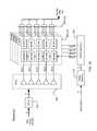
- FIG. 2is a block diagram of one embodiment of a receiver compatible with the transmitter of FIG. 1 .
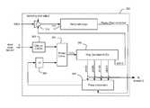
- FIG. 3is a block diagram detailing one embodiment of the clock recovery circuit used by the receiver of FIG. 2 .
- FIG. 4is a timing diagram showing the interaction between the recovered clocks and received data in the embodiments of FIGS. 2 and 3 .
- FIG. 5is a flowchart of a process, in accordance with at least one embodiment
- FIG. 6is a block diagram of one embodiment configured to encode and transmit 4 bits and a clock on a six-wire communications channel.
- FIG. 7is a block diagram of an embodiment of a receiver compatible with the transmitter of FIG. 6 .
- FIG. 8is a block diagram detailing on embodiment of the clock recovery circuit used by the receiver of FIG. 7 .
- FIG. 9is a block diagram of one embodiment configured to encode and transmit 5 bits on a six-wire communications channel using a transition encoder.
- FIG. 10is a block diagram of an embodiment of a receiver compatible with the transmitter of FIG. 9 .
- vector signaling codesmay be used to produce extremely high bandwidth data communications links, such as between two integrated circuit devices in a system.
- Multiple data communications channelstransmit symbols of the vector signaling code, acting together to communicate codewords of the vector signaling code.
- the number of channels comprising a communications linkmay range from two to eight or more.
- Individual symbols, e.g. transmissions on any single communications channelmay utilize multiple signal levels, often three or more. Operation at channel rates exceeding 10 Gbps may further complicate receive behavior by requiring deeply pipelined or parallelized signal processing, precluding reception methods that require the previous received value to be known as the current value is being received.
- Embodiments described hereincan also be applied to prior art permutation sorting methods not covered by the vector processing methods of [Cronie II], [Cronie III], [Cronie IV], and/or [Tajalli I]. More generally, embodiments can apply to any communication or storage methods requiring coordination of multiple channels or elements of the channel to produce a coherent aggregate result.
- sampling deviceperforms a measurement constrained in both time and amplitude dimensions; in one example embodiment, it may be comprised of a sample-and-hold circuit that constrains the time interval being measured, followed by a threshold detector or digital comparator that determines whether the signal within that interval falls above or below (or in some embodiments, within bounds set by) a reference value. Alternatively, a digital comparator may determine the signal amplitude followed by a clocked digital flip-flop capturing the result at a selected time.
- sampling deviceor more simply “sampler” to describe this receiver input measurement function as it implies both the time and amplitude measurement constraints, rather than the equivalent but less descriptive term “slicer” also used in the art.
- receiver “eye plot”graphically illustrates input signal values that will or will not provide accurate and reliable detected results from such measurement, and thus the allowable boundaries of the time and amplitude measurement windows imposed on the sampler.
- sampling deviceor more simply “sampler” as it implies both the time and amplitude measurement constraints, rather than the equivalent but less descriptive term “slicer” also used in the art.
- So-called Clock Data Recovery or CDR circuitssupport such sampling measurements by extracting timing information, either from the data lines themselves or from dedicated clock signal inputs, and utilize that extracted information to generate clock signals to control the time interval used by the data line sampling device(s).
- the actual clock extractionmay be performed using well known circuits such as a Phase Locked Loop (PLL) or Delay Locked Loop (DLL), which in their operation may also generate higher frequency internal clocks, multiple clock phases, etc. in support of receiver operation.
- PLLPhase Locked Loop
- DLLDelay Locked Loop
- the interconnection wiring between transmitter and receivermay be of significant length and/or have significantly distinct transmission line characteristics across the set of signal wires, leading to differential amplitude, frequency, and timing characteristics among the data wires and between the data wires and any dedicated clock wires.
- the design of the integrated circuit transmitter and receivermay be different for data wires and for clock wires based on the different internal processing performed for data and for clock signals, leading to an inevitable differential timing behavior between those signal inputs.
- the phase relationships among the various signalsmay vary over time or with supply voltage, potentially requiring periodic adjustment.
- One embodiment described hereinincorporates a receiver using four parallel processing slices associated with respective phases, each phase sampling, detecting, and decoding the vector code communicated during a single unit interval.
- the wires carrying the transmitted clock informationmay be used as proxies or analogs for the data wires in said transition time measurement.
- timing-related operationsare limited to the clock information wires, and data sampling operations to the data wires in this simplified receiver design.
- FIG. 1One embodiment of a transmitter is shown in the block diagram of FIG. 1 .
- datais communicated using a 5b6w vector signaling code as described in [Shokrollahi II], thus encoder 110 accepts five transmit data bits and encodes them into a six element codeword which, when emitted by line drivers 130 , will be carried by six wires of the communications medium.
- a clock signalis encoded by clock encoder 120 and emitted by line driver 130 to be carried by the remaining two wires of the communications medium.
- the clock signal transmitted at the same signal levels as the encoded data, in an encoded format equivalent to a differential square wave clock at one eighth ratethus, as examples without implying limitation, corresponding to four consecutive unit intervals of “high” signal level on the first clock wire and “low” signal level on the second clock wire, followed by four consecutive unit intervals of “low” signal level on the first clock wire and “high” signal level on the second clock wire, where “high” and “low” are chosen from the set of signal levels used to carry data codeword values.
- one transmitter embodimentutilizes identical control logic and drivers to generate signals on all eight communications wires.
- data encoder 110 and clock encoder 120have essentially equal propagation delays and all line drivers 130 are identical.
- Some embodimentsmay further align transmission by using a common clock signal to control the emission of new output values from the line drivers.
- the transmitted clock signalmay be interpreted as another vector encoded data signal communicating one bit of clock information on two wires, albeit an encoded signal that continuously repeats the same eight unit interval pattern.
- the transmitter embodiment described hereinis shown as utilizing a single processing phase, while the receiver embodiment is shown as utilizing four parallel processing phases, in neither case implying a limitation.
- fewer or greater numbers of processing phasesencompassing smaller or greater portions of the system may be utilized in combination with described embodiments.
- vector signaling codesmay be efficiently detected by linearly combining sets of input signals using Multi-Input comparators or mixers (MIC).
- MICMulti-Input comparators or mixers
- 5b6w codealso referred to herein as the Glasswing code
- five such mixers acting on weighted subsets of the six received data input signalswill detect the five data bits without need of further decoding.
- MIC outputsare differential analog levels that will later be sliced and sampled by digital comparators and/or flip-flops.
- the MICsare configured to perform a slicing operation, and the MIC outputs only need to be sampled.
- One additional mixer acting on combinations of the two received clock signalswill similarly detect the non-skewed reference clock signal.
- one embodiment of a data receiveris composed of eight identical CTLE stages 210 operating on the six data wires and two clock wires. This collection of equalized received signals is presented to a set of six MIC mixers 220 .
- W 0 -W 7are the (optionally amplified and equalized) signals received from communication wires 0 - 7 .
- the five MIC outputs MIC 0 -MIC 4are processed using a plurality of processing slices in four parallel phases of receive data processing, each phase 230 including five data sampling units and subsequent buffering, followed by recombination of the four phase MIC outputs into a received data stream, shown in FIG. 2 as being performed by multiplexers 240 .
- CTLE outputs W 6 and W 7are presented with loads (e.g. the number of driven MIC input transistors in the [Ulrich I] design) that are comparable to the loads placed on the other CTLE outputs to minimize differential propagation delay effects.
- loadse.g. the number of driven MIC input transistors in the [Ulrich I] design
- the receiver clock recovery PLL 300performs two operations. First, it multiplies the input clock frequency and generates four phased sampling clocks suitable for triggering the samplers of the four data phases, once per received unit interval. Second, it generates an additional sampling clock suitable for triggering the clock sampler, the result of which will be used to adjust the overall PLL phase such that the data sampling occurs at or near the center of the received eye pattern.
- a local ring oscillator 340comprising a sequence of identical gates in a closed loop is used as the internal Voltage Controlled Oscillator (VCO) timing source for the PLL.
- the VCO frequencyis varied by analog adjustment of at least one of: gate propagation delay, inter-gate rise and fall time, and gate switching threshold within the local ring oscillator.
- Outputs taken at equal intervals (i.e. separated by equal numbers of ring oscillator gates) along the sequence of gates comprising the ring oscillatorprovide the four phased sampling clocks, herein identified as the 0, 90, 180, and 270 degree clocks.
- One additional output tap at half of interval between the 270 and 0 degree tapsprovides another sampling clock identified as the 315 degree clock.
- the local ring oscillatorcomprises eight identical sets of logic gates, thus the phase difference from one such set to the next is 45 degrees.
- the 0, 90, 180, and 270 degree outputsmay be obtained, as examples, from the second, fourth, sixth, and eighth outputs, while the 315 degree output in the same example may be obtained from the first output.
- the location of the 0 degree tapis arbitrary, as one familiar with the art will recognize that normal PLL behavior will phase align the local ring oscillator with the external phase reference regardless of its initial phase.
- equivalent designsmay be obtained in which the phased sampling clocks do not have square wave duty cycles; as one example being produced by the action of AND or OR gates with inputs from different tap locations.
- the 315 degree clockis well suited to capture the rising or falling edge of the non-skewed reference signal, as ideally all input signals transition one half UI (that is, one half clock span) before the desirable center-of-eye data sampling region. As the non-skewed reference signal alternates four UIs high and four UIs low, the same 315 degree clock will alternately sample the clock rising and falling edge.
- local ring oscillator 340 outputis divided by two using a flip-flop 360 and presented as one input to a conventional CMOS phase comparator 330 .
- the other phase comparator inputis a skewed reference signal provided by a conventional CML-to-CMOS 320 converter driven by the non-CTLE clock signals W 6 and W 7 .
- the CML-to-CMOS 320 converteris configured to receive a differential input signal, and continuously output a single ended signal.
- the single ended signalrepresents a digital waveform.
- the comparator input provided by the conventional CML-to-CMOS 320 convertermay have an associated skew error introduced by the converter 320 , and therefore is a skewed reference signal.
- the CML-to-CMOS converter 320approximates the delay characteristics of CTLE stages 210 , and the associated skew error corresponds to any differences.
- the CML-to-CMOS converteraccepts the non-skewed reference signal MIC 5 (which is at CML logic levels at its clock MIC source) as a differential input and provides the skewed reference signal to the phase comparator.
- the associated skew erroralso corresponds in part directly to the skew introduced by CML-to-CMOS converter 320 .
- FIG. 8An example of a clock recovery circuit accepting only a differential MIC output is depicted by FIG. 8 .
- Phase comparator 330produces output Error (also referred to herein as an oscillator adjustment signal), which is an analog signal proportional to both the sign and magnitude of the difference between the timing of the signal edges of its two inputs.
- Erroralso referred to herein as an oscillator adjustment signal
- the oscillator adjustment signalcontrols the local ring oscillator 340 frequency, such that in PLL lock there will be a fixed phase relationship (e.g. zero degrees) between the two phase comparator inputs, and the local ring oscillator will be operating at twice the input clock frequency.
- the local ring oscillator output presented to the divideris obtained from a phase interpolator 350 as a phase offset feedback signal having a phase offset that corresponds to an estimated skew error (which may be introduced by converter 320 in some embodiments), and wherein the phase is controllably intermediate between its input phased sampling clocks.
- the PLLmay lock with its fixed phase relationship, while the internal clock signals obtained from local ring oscillator 340 will be offset from that fixed phase by the phase delay amount introduced by phase interpolator 350 , as controlled by signal Phase offset correction, based on an independent phase measurement made on the sampled non-skewed reference signal.
- Phase interpolatorsare known in the art, one example being provided by [Buchwald I].
- phase interpolator 350receives eight distinct phased sampling clocks from the local ring oscillator having 45 degree phase differences. Said phase interpolator may be controlled to select two adjacent phased sampling clocks and then to interpolate between them so as to produce the phase offset feedback signal at a chosen phase offset between those selected two values.
- Data sampling unit 310samples the raw MIC 5 non-skewed reference signal as triggered by clock ph 315 , producing a binary (e.g. sign only) early/late timing indication. Under optimum conditions, this sample timing will be concurrent with rising and falling clock edges producing statistically equal percentages of early vs late indications, and Early/Late logic 370 will not modify the existing phase interpolator setting. Conversely if the indications are consistently early or consistently late, Early/Late logic 370 will increment or decrement the phase interpolator offset signal by a fixed amount, in an attempt to align the sampling interval with the non-skewed reference signal transitions.
- the independent phase measurement made by Early/Late Logic 370may be subsumed by control software executing in a system management processor.
- a comparable functionmay be performed by an analog or digital low-pass filter integrating the early/late indications to produce a correction signal for the phase interpolator, as well understood in the art.
- the phase interpolator settingmay only require infrequent adjustment.
- sampler 310As the rising and falling edges of the MIC 5 non-skewed reference signal are significantly ramped (due to the inevitable high frequency attenuation over practical communications channels at 25 Gbps) small changes in sampler 310 amplitude threshold can produce comparable incremental adjustments in the transition timing, and thus produce incremental timing offsets in the resulting sampling clocks.
- analog signal Sampling level adjustis input to sampler 310 to permit this small incremental adjustment as controlled by an external command/control or administrative interface.
- phase detector designwhich drives the PLL to lock with a zero phase differential between the two phase detector inputs.
- applying the 0 and 90-degree clock phases as inputs to the phase interpolatorallows adjustment such that the PLL leads the reference clock input by between 0 and 90 degrees.
- equivalent results with comparable phase offsetsmay be obtained using other pairs of degree clocks and/or other phase detector designs (e.g. other known phase detector designs drive the PLL to lock with a 90 degree phase differential) thus neither the particular phase clocks chosen nor the particular phase detector design described herein are limiting.
- FIG. 4details the relationship between received data and clock signals and the internally generated clocks in the example receiver embodiment.
- the clock phases obtained from the ring oscillatorare shown as square waves, without limitation, as only the rising edge of said clocks are used in the description.
- Signals MIC 0 - 4are the five detected data MIC outputs from MICs 220 of FIG. 2
- signal MIC 5is the corresponding non-skewed reference signal.
- the clock recovery PLL of FIG. 4produces four phased sampling clocks ph 000 , ph 090 , ph 180 , and ph 270 , each having a rising edge corresponding to the optimum sampling time to capture received data from consecutive UIs of MIC 0 - 4 , as in 410 , 420 , 430 , 440 , 450 , 460 , 470 , 480 .
- the half-UI-offset clock ph 315has a rising edge corresponding to rising and falling edges of received non-skewed reference clock signal MIC 5 , as shown at 490 and 495 .
- aligning ph 315 with the clock edgeswill simultaneously position ph 000 , ph 090 , phi 80 , and ph 270 for optimum data sampling within the four parallel receiver processing slices phase 0 , phase 1 , phase 2 , and phase 3 of FIG. 2 .
- an apparatuscomprises a phase interpolator configured to operate on a pair of local oscillator feedback signals and an independent phase measurement made on a sampled non-skewed reference signal and to responsively generate a phase offset feedback signal having a phase offset corresponding to an estimated skew error, and, a phase comparator configured to receive a skewed reference signal having an associated skew error and the phase offset feedback signal, and to generate an oscillator adjustment signal representing in part a difference between the estimated skew error and the associated skew error.
- a method 500includes the steps of receiving, at step 502 , a pair of local oscillator feedback signals and an independent phase measurement made on a sampled non-skewed reference signal, generating, at step 504 , a phase offset feedback signal having a phase offset corresponding to an estimated skew error, receiving, at step 506 , a skewed reference signal having an associated skew error and the phase offset feedback signal, and generating, at step 508 , an oscillator adjustment signal representing in part a difference between the estimated skew error and the associated skew error.
- FIG. 7is similar to the embodiment shown in FIG. 2 , the only difference being that rather than encoding a clock signal separately, the encoded clock signal is embedded into the sub-channel associated with MIC 4 .
- the CML-to-CMOS converteraccepts the MIC 4 signal as a differential input (as shown in an embodiment of a clock recover circuit depicted by FIG. 8 ), as there are no dedicated clock wires in the communication bus for such an embodiment.
- MIC 4may be configured to transition every fourth cycle (similar to MIC 5 above), in which case the differential signals input to CML-to-CMOS converter 320 will cause a binary output to change every fourth cycle.
- the sub-channel defined by Eqn. 5is designated to carry the embedded clock, as its symmetry and delay characteristics in a practical embodiment were found to be conducive to integration with the delay-and-sample behavior of conventional clock/data recovery circuits.
- FIG. 9A transmitter in accordance with such transition embodiments is shown in FIG. 9 .
- the transition pre-coded transmit datais pre-coded so that at least one bit changes each transmission unit interval, for example using methods or apparatuses described in [Shokrollahi I].
- FIG. 10illustrates an embodiment of a receiver that is compatible with the transmitter of FIG. 9 .
- An edge detector 1010is configured to detect a transition among MIC outputs MIC 0 -MIC 4 , and use the transitions to provide the non-skewed reference signal to the clock recovery circuit 300 .
- the CML-to-CMOS converter and clock sampleraccept a differential signal provided by the edge detector.
- the edge detector 1010in order to reduce the frequency of the non-skewed reference signal, the edge detector 1010 could be configured to detect every fourth edge, using a counter and flip-flops for example. Also, other known methods and devices may be used to reduce the frequency of the non-skewed reference signal. Embodiments using transition codes have a benefit of increased pin-efficiency at the cost of increased encoding/decoding complexity.
Landscapes
- Engineering & Computer Science (AREA)
- Computer Networks & Wireless Communication (AREA)
- Signal Processing (AREA)
- Power Engineering (AREA)
- Physics & Mathematics (AREA)
- Spectroscopy & Molecular Physics (AREA)
- Synchronisation In Digital Transmission Systems (AREA)
Abstract
Description
The following prior applications are herein incorporated by reference in their entirety for all purposes:
U.S. Patent Publication 2011/0268225 of application Ser. No. 12/784,414, filed May 20, 2010, naming Harm Cronie and Amin Shokrollahi, entitled “Orthogonal Differential Vector Signaling” (hereinafter “Cronie I”).
U.S. Patent Publication 2011/0302478 of application Ser. No. 12/982,777, filed Dec. 30, 2010, naming Harm Cronie and Amin Shokrollahi, entitled “Power and Pin Efficient Chip-to-Chip Communications with Common-Mode Resilience and SSO Resilience” (hereinafter “Cronie II”).
U.S. patent application Ser. No. 13/030,027, filed Feb. 17, 2011, naming Harm Cronie, Amin Shokrollahi and Armin Tajalli, entitled “Methods and Systems for Noise Resilient, Pin-Efficient and Low Power Communications with Sparse Signaling Codes” (hereinafter “Cronie III”).
U.S. patent application Ser. No. 13/176,657, filed Jul. 5, 2011, naming Harm Cronie and Amin Shokrollahi, entitled “Methods and Systems for Low-power and Pin-efficient Communications with Superposition Signaling Codes” (hereinafter “Cronie IV”).
U.S. patent application Ser. No. 13/542,599, filed Jul. 5, 2012, naming Armin Tajalli, Harm Cronie, and Amin Shokrollhi entitled “Methods and Circuits for Efficient Processing and Detection of Balanced Codes” (hereafter called “Tajalli I”.)
U.S. patent application Ser. No. 13/842,740, filed Mar. 15, 2013, naming Brian Holden, Amin Shokrollahi and Anant Singh, entitled “Methods and Systems for Skew Tolerance in and Advanced Detectors for Vector Signaling Codes for Chip-to-Chip Communication”, hereinafter identified as [Holden I].
U.S. patent application Ser. No. 14/816,896, filed Aug. 3, 2015, naming Brian Holden and Amin Shokrollahi, entitled “Orthogonal Differential Vector Signaling Codes with Embedded Clock”, hereinafter identified as [Holden II].
U.S. Provisional Patent Application No. 61/946,574, filed Feb. 28, 2014, naming Amin Shokrollahi, Brian Holden, and Richard Simpson, entitled “Clock Embedded Vector Signaling Codes”, hereinafter identified as [Shokrollahi I].
U.S. patent application Ser. No. 14/612,241, filed Aug. 4, 2015, naming Amin Shokrollahi, Ali Hormati, and Roger Ulrich, entitled “Method and Apparatus for Low Power Chip-to-Chip Communications with Constrained ISI Ratio”, hereinafter identified as [Shokrollahi II].
U.S. patent application Ser. No. 13/895,206, filed May 15, 2013, naming Roger Ulrich and Peter Hunt, entitled “Circuits for Efficient Detection of Vector Signaling Codes for Chip-to-Chip Communications using Sums of Differences”, hereinafter identified as [Ulrich I].
The following additional references to prior art have been cited in this application:
U.S. Pat. No. 6,509,773, filed Apr. 30, 2001 by Buchwald et al., entitled “Phase interpolator device and method” (hereafter called “Buchwald I”.)
“A 3×9 Gb/s Shared, All-Digital CDR for High-Speed, High-Density I/O”, Matthew Loh, Azita Emami-Neyestanak, IEEE Journal of Solid-State Circuits, Vo. 47, No. 3, March 2012 (hereafter called “Loh I”.]
Present embodiments relate to communications systems circuits generally, and more particularly to obtaining a stable, correctly phased receiver clock signal from a high-speed multi-wire interface used for chip-to-chip communication.
In modern digital systems, digital information has to be processed in a reliable and efficient way. In this context, digital information is to be understood as information available in discrete, i.e., discontinuous values. Bits, collection of bits, but also numbers from a finite set can be used to represent digital information.
In most chip-to-chip, or device-to-device communication systems, communication takes place over a plurality of wires to increase the aggregate bandwidth. A single or pair of these wires may be referred to as a channel or link and multiple channels create a communication bus between the electronic components. At the physical circuitry level, in chip-to-chip communication systems, buses are typically made of electrical conductors in the package between chips and motherboards, on printed circuit boards (“PCBs”) boards or in cables and connectors between PCBs. In high frequency applications, microstrip or stripline PCB traces may be used.
Common methods for transmitting signals over bus wires include single-ended and differential signaling methods. In applications requiring high speed communications, those methods can be further optimized in terms of power consumption and pin-efficiency, especially in high-speed communications. More recently, vector signaling methods have been proposed to further optimize the trade-offs between power consumption, pin efficiency and noise robustness of chip-to-chip communication systems. In those vector signaling systems, digital information at the transmitter is transformed into a different representation space in the form of a vector codeword that is chosen in order to optimize the power consumption, pin-efficiency and speed trade-offs based on the transmission channel properties and communication system design constraints. Herein, this process is referred to as “encoding”. The encoded codeword is communicated as a group of signals from the transmitter to one or more receivers. At the receiver, the received signals corresponding to the codeword are transformed back into the original digital information representation space. Herein, this process is referred to as “decoding”.
Regardless of the encoding method used, the received signals presented to the receiving device must be sampled (or their signal value otherwise recorded) at intervals best representing the original transmitted values, regardless of transmission channel delays, interference, and noise. This Clock and Data Recovery (CDR) not only must determine the appropriate sample timing, but must continue to do so continuously, providing dynamic compensation for varying signal propagation conditions.
In a communications system incorporating multiple data communications signals and at least one dedicated clock signal, a receiver must not only reliably detect the data values and synchronize to the dedicated clock signal, but must also be configurable to align the resulting synthesized clock with the received data to optimize receive data sampling. Conventionally, such alignment requires introduction of additional data sampling stages configured to detect data edge transitions that then serve as alignment references for subsequent clock phase adjustment.
In comparison, the described receiver system performs both clock synthesis and edge detection upon the received clock signal. The resulting design is both simpler and easier to scale to higher speed operation with minimal power consumption.
As described in [Cronie I], [Cronie II], [Cronie III] and [Cronie IV], vector signaling codes may be used to produce extremely high bandwidth data communications links, such as between two integrated circuit devices in a system. Multiple data communications channels transmit symbols of the vector signaling code, acting together to communicate codewords of the vector signaling code. Depending on the particular vector signaling code used, the number of channels comprising a communications link may range from two to eight or more. Individual symbols, e.g. transmissions on any single communications channel, may utilize multiple signal levels, often three or more. Operation at channel rates exceeding 10 Gbps may further complicate receive behavior by requiring deeply pipelined or parallelized signal processing, precluding reception methods that require the previous received value to be known as the current value is being received.
Embodiments described herein can also be applied to prior art permutation sorting methods not covered by the vector processing methods of [Cronie II], [Cronie III], [Cronie IV], and/or [Tajalli I]. More generally, embodiments can apply to any communication or storage methods requiring coordination of multiple channels or elements of the channel to produce a coherent aggregate result.
Input Sampling Circuits
Conventional practice for a high-speed integrated circuit receiver requires each data line to terminate (after any relevant front end processing such as amplification and frequency equalization) in a sampling device. This sampling device performs a measurement constrained in both time and amplitude dimensions; in one example embodiment, it may be comprised of a sample-and-hold circuit that constrains the time interval being measured, followed by a threshold detector or digital comparator that determines whether the signal within that interval falls above or below (or in some embodiments, within bounds set by) a reference value. Alternatively, a digital comparator may determine the signal amplitude followed by a clocked digital flip-flop capturing the result at a selected time. In another embodiment, it may be comparable to an edge-triggered D flip-flop, sampling the state of its input in response to a clock transition. Subsequently, this document will use the term sampling device, or more simply “sampler” to describe this receiver input measurement function as it implies both the time and amplitude measurement constraints, rather than the equivalent but less descriptive term “slicer” also used in the art.
The well known receiver “eye plot” graphically illustrates input signal values that will or will not provide accurate and reliable detected results from such measurement, and thus the allowable boundaries of the time and amplitude measurement windows imposed on the sampler. This document will henceforth use the term sampling device, or more simply “sampler” as it implies both the time and amplitude measurement constraints, rather than the equivalent but less descriptive term “slicer” also used in the art.
So-called Clock Data Recovery or CDR circuits support such sampling measurements by extracting timing information, either from the data lines themselves or from dedicated clock signal inputs, and utilize that extracted information to generate clock signals to control the time interval used by the data line sampling device(s). The actual clock extraction may be performed using well known circuits such as a Phase Locked Loop (PLL) or Delay Locked Loop (DLL), which in their operation may also generate higher frequency internal clocks, multiple clock phases, etc. in support of receiver operation.
As there may be unavoidable timing skews between signal lines and the recovered clock, it is common practice to incorporate secondary data line sampling circuits which may be intentionally offset by controlled amounts of time and/or amplitude, so as to determine the receive eye edges and thus discern whether the data sample timing or threshold level is optimally configured. One example of such art is given by [Loh I]. Unfortunately, the addition of such secondary sampling circuits to multiple high-speed data inputs requires a significant increase in integrated circuit real estate, and well as producing a substantial increase in power consumption.
Such secondary sampling is required in conventional designs for several reasons. First, the interconnection wiring between transmitter and receiver may be of significant length and/or have significantly distinct transmission line characteristics across the set of signal wires, leading to differential amplitude, frequency, and timing characteristics among the data wires and between the data wires and any dedicated clock wires. Second, the design of the integrated circuit transmitter and receiver may be different for data wires and for clock wires based on the different internal processing performed for data and for clock signals, leading to an inevitable differential timing behavior between those signal inputs. Finally, the phase relationships among the various signals may vary over time or with supply voltage, potentially requiring periodic adjustment. Thus, it is impractical for a conventional embodiment to rely upon a particular predetermined timing relationship between a clock input and an appropriate data sampling interval, as a result of these unpredictable or variable sources of timing error.
System Environment
Unlike the complex and variable transmission line environments seen in general purpose communications networks, it is possible to tightly constrain the operating environment for communication between, for example, two closely spaced integrated circuit devices on the same printed circuit board. In such an environment, communication path distances are measured in millimeters rather than centimeters or meters, and transmission line characteristics may be tightly controlled by imposing strict design rules on trace routing and spacing. These constraints allow differential wire skew to be limited by design to a fraction of a transmission unit interval.
For purposes of description and without implying limitation, the following examples assume a communications system environment comprising interconnection of one transmitting and one receiving integrated circuit device via eight signal wires of equal path length up to 25 millimeters and identical transmission line characteristics, at signaling rates up to 25 Gigabit/second/wire, equivalent to a transmission unit interval of 40 picoseconds. In such an example environment, adequate signal reception may be obtained using Continuous Time Linear Equalization or CTLE, without need for advanced receive equalization such as obtained using Decision Feedback Equalization or DFE methods.
One embodiment described herein incorporates a receiver using four parallel processing slices associated with respective phases, each phase sampling, detecting, and decoding the vector code communicated during a single unit interval. Thus, each phase has as much as 4*40=160 picoseconds to perform the necessary processing.
Ramifications of the Constrained System Environment
Given the design constraints placed upon the multiple signal wires comprising the communications medium and a further constraint that the transmitter emit signals essentially simultaneously on the various wires and that the receiver similarly attempts to maintain equal-time propagation of the received signals from the various wires, a significant design simplification may be made. Rather than requiring measurement of the signal transition times at each data wire as well as performing the necessary center-of-eye sampling to obtain the relevant data values, the wires carrying the transmitted clock information may be used as proxies or analogs for the data wires in said transition time measurement. Thus, timing-related operations are limited to the clock information wires, and data sampling operations to the data wires in this simplified receiver design.
One familiar with the art may note that conventional receiver PLL designs, as one example, already obtain clock timing information from clock information wires, to serve as an external phase reference for the PLL internal oscillator. However, in the known art this is a fixed relationship, and is thus not informed by subtleties of receive eye shape, symmetry, etc. which are well known to influence the correct timing of a data measurement or sampling operation on the received data values. Moreover, this phase relationship may vary undesirably as a result of changes in temperature, power supply voltage, or other characteristics of the communication system devices. In contrast, the embodiments described herein utilize signals from the clock information wires not only as a phase reference for the phase-locked loop, but also as a proxy or analog of a data wire signal transition measurement to determine an appropriate offset from that phase reference to optimize data wire sample timing.
Transmitter
One embodiment of a transmitter is shown in the block diagram ofFIG. 1 . In this embodiment, data is communicated using a 5b6w vector signaling code as described in [Shokrollahi II], thus encoder110 accepts five transmit data bits and encodes them into a six element codeword which, when emitted byline drivers 130, will be carried by six wires of the communications medium. Simultaneously, a clock signal is encoded byclock encoder 120 and emitted byline driver 130 to be carried by the remaining two wires of the communications medium. In this embodiment, the clock signal transmitted at the same signal levels as the encoded data, in an encoded format equivalent to a differential square wave clock at one eighth rate thus, as examples without implying limitation, corresponding to four consecutive unit intervals of “high” signal level on the first clock wire and “low” signal level on the second clock wire, followed by four consecutive unit intervals of “low” signal level on the first clock wire and “high” signal level on the second clock wire, where “high” and “low” are chosen from the set of signal levels used to carry data codeword values.
To ensure that all transitions on all communications wires are simultaneous at the transmitter, one transmitter embodiment utilizes identical control logic and drivers to generate signals on all eight communications wires. Thus,data encoder 110 andclock encoder 120 have essentially equal propagation delays and allline drivers 130 are identical. Some embodiments may further align transmission by using a common clock signal to control the emission of new output values from the line drivers. One familiar with the art will understand that under such conditions the transmitted clock signal may be interpreted as another vector encoded data signal communicating one bit of clock information on two wires, albeit an encoded signal that continuously repeats the same eight unit interval pattern.
For purposes of illustration the transmitter embodiment described herein is shown as utilizing a single processing phase, while the receiver embodiment is shown as utilizing four parallel processing phases, in neither case implying a limitation. Depending on the available integrated circuit process capabilities and overall data throughput requirements, fewer or greater numbers of processing phases encompassing smaller or greater portions of the system may be utilized in combination with described embodiments.
Receiver Data Detection
As described in [Holden I] and [Ulrich I], vector signaling codes may be efficiently detected by linearly combining sets of input signals using Multi-Input comparators or mixers (MIC). For the example 5b6w code (also referred to herein as the Glasswing code), five such mixers acting on weighted subsets of the six received data input signals will detect the five data bits without need of further decoding. In some embodiments, MIC outputs are differential analog levels that will later be sliced and sampled by digital comparators and/or flip-flops. In other embodiments, the MICs are configured to perform a slicing operation, and the MIC outputs only need to be sampled. One additional mixer acting on combinations of the two received clock signals will similarly detect the non-skewed reference clock signal.
As shown inFIG. 2 , one embodiment of a data receiver is composed of eight identical CTLE stages210 operating on the six data wires and two clock wires. This collection of equalized received signals is presented to a set of sixMIC mixers 220. As described in [Shokrollahi II] a set of multi input comparators detecting the 5b6w code are:
MIC0=W0−W1 (Eqn. 1)
MIC1=½W0+½W1−W2 (Eqn. 2)
MIC2=W3−W4 (Eqn. 3)
MIC3=½W3+½W4−W5 (Eqn. 4)
MIC4=⅓W0+⅓W1+⅓W2−⅓W3−⅓W4−⅓W5 (Eqn. 5)
MIC0=W0−W1 (Eqn. 1)
MIC1=½W0+½W1−W2 (Eqn. 2)
MIC2=W3−W4 (Eqn. 3)
MIC3=½W3+½W4−W5 (Eqn. 4)
MIC4=⅓W0+⅓W1+⅓W2−⅓W3−⅓W4−⅓W5 (Eqn. 5)
Similarly, the described encoded clock may be detected as:
MIC5=W6−W7 (Eqn. 6)
MIC5=W6−W7 (Eqn. 6)
Where W0-W7 are the (optionally amplified and equalized) signals received from communication wires0-7.
The five MIC outputs MIC0-MIC4 are processed using a plurality of processing slices in four parallel phases of receive data processing, eachphase 230 including five data sampling units and subsequent buffering, followed by recombination of the four phase MIC outputs into a received data stream, shown inFIG. 2 as being performed bymultiplexers 240.
The detected non-skewed reference signal (also referred to herein as a detected clock signal) MIC5 and non-CTLE clock signals W6-W7 are processed by the receiverclock recovery PLL 300 which extracts the received clock signal and produces multiple phased sampling clocks (i.e. internal clocks of appropriate rates and phases). In particular, phased sampling clock ph000 is aligned to optimally trigger data sampling units in the phase0 phase of processing, clock ph090 in phase1, clock ph180 in phase2, and clock ph270 in phase3.
One knowledgeable in the field will note that utilizing the same processing steps and circuit designs for all input signals and maintaining consistent circuit loading across data and clock circuit nodes minimizes the introduction of differential delays among the received signals. In at least one embodiment, these practices extend to equal-length signal path routing from external I/O connections to the chip and then within the integrated circuit, and “star” termination of each wire input via on-chip resistors connected at a single point. Similarly, [Ulrich 1] describes an efficient MIC design in which the input scale factors are represented using sets of identical transistors. In one alternative embodiment incorporating a MIC design of this type, Eqn. 6 is rewritten to be
MIC5=W6+W6+W7−W6−W7−W7 (Eqn. 7)
so that CTLE outputs W6 and W7 are presented with loads (e.g. the number of driven MIC input transistors in the [Ulrich I] design) that are comparable to the loads placed on the other CTLE outputs to minimize differential propagation delay effects.
Receiver Clock Recovery
The receiverclock recovery PLL 300 performs two operations. First, it multiplies the input clock frequency and generates four phased sampling clocks suitable for triggering the samplers of the four data phases, once per received unit interval. Second, it generates an additional sampling clock suitable for triggering the clock sampler, the result of which will be used to adjust the overall PLL phase such that the data sampling occurs at or near the center of the received eye pattern.
One such PLL embodiment is illustrated inFIG. 3 . Alocal ring oscillator 340 comprising a sequence of identical gates in a closed loop is used as the internal Voltage Controlled Oscillator (VCO) timing source for the PLL. The VCO frequency is varied by analog adjustment of at least one of: gate propagation delay, inter-gate rise and fall time, and gate switching threshold within the local ring oscillator. Outputs taken at equal intervals (i.e. separated by equal numbers of ring oscillator gates) along the sequence of gates comprising the ring oscillator provide the four phased sampling clocks, herein identified as the 0, 90, 180, and 270 degree clocks. One additional output tap at half of interval between the 270 and 0 degree taps provides another sampling clock identified as the 315 degree clock.
In one embodiment, the local ring oscillator comprises eight identical sets of logic gates, thus the phase difference from one such set to the next is 45 degrees. In this embodiment, the 0, 90, 180, and 270 degree outputs may be obtained, as examples, from the second, fourth, sixth, and eighth outputs, while the 315 degree output in the same example may be obtained from the first output. As many variations of such designs are known in the art, neither the number of elements in the local ring oscillator nor the specific taps at which particular outputs are made should be construed as implying a limitation. As one example, the location of the 0 degree tap is arbitrary, as one familiar with the art will recognize that normal PLL behavior will phase align the local ring oscillator with the external phase reference regardless of its initial phase. Similarly, equivalent designs may be obtained in which the phased sampling clocks do not have square wave duty cycles; as one example being produced by the action of AND or OR gates with inputs from different tap locations.
One familiar with the art will recognize the 315 degree clock as being equivalent to a clock having a −45 degree phase relative to the 0 degree clock, i.e. occurring earlier than the 0 degree clock by one-half of the 90 degree span between phased data sampling clocks. Thus, the 315 degree clock is well suited to capture the rising or falling edge of the non-skewed reference signal, as ideally all input signals transition one half UI (that is, one half clock span) before the desirable center-of-eye data sampling region. As the non-skewed reference signal alternates four UIs high and four UIs low, the same 315 degree clock will alternately sample the clock rising and falling edge.
Following conventional PLL design,local ring oscillator 340 output is divided by two using a flip-flop 360 and presented as one input to a conventionalCMOS phase comparator 330. The other phase comparator input is a skewed reference signal provided by a conventional CML-to-CMOS 320 converter driven by the non-CTLE clock signals W6 and W7. In some embodiments, the CML-to-CMOS 320 converter is configured to receive a differential input signal, and continuously output a single ended signal. In some embodiments, the single ended signal represents a digital waveform. The comparator input provided by the conventional CML-to-CMOS 320 converter may have an associated skew error introduced by theconverter 320, and therefore is a skewed reference signal. In some embodiments, the CML-to-CMOS converter 320 approximates the delay characteristics of CTLE stages210, and the associated skew error corresponds to any differences. In some embodiments, the CML-to-CMOS converter accepts the non-skewed reference signal MIC5 (which is at CML logic levels at its clock MIC source) as a differential input and provides the skewed reference signal to the phase comparator. In such embodiments, the associated skew error also corresponds in part directly to the skew introduced by CML-to-CMOS converter 320. An example of a clock recovery circuit accepting only a differential MIC output is depicted byFIG. 8 .Phase comparator 330 produces output Error (also referred to herein as an oscillator adjustment signal), which is an analog signal proportional to both the sign and magnitude of the difference between the timing of the signal edges of its two inputs. Following conventional PLL practice, the oscillator adjustment signal controls thelocal ring oscillator 340 frequency, such that in PLL lock there will be a fixed phase relationship (e.g. zero degrees) between the two phase comparator inputs, and the local ring oscillator will be operating at twice the input clock frequency.
To allow the overall phase of the locked PLL signals to be offset from the reference clock input phase, the local ring oscillator output presented to the divider is obtained from aphase interpolator 350 as a phase offset feedback signal having a phase offset that corresponds to an estimated skew error (which may be introduced byconverter 320 in some embodiments), and wherein the phase is controllably intermediate between its input phased sampling clocks. Thus, the PLL may lock with its fixed phase relationship, while the internal clock signals obtained fromlocal ring oscillator 340 will be offset from that fixed phase by the phase delay amount introduced byphase interpolator 350, as controlled by signal Phase offset correction, based on an independent phase measurement made on the sampled non-skewed reference signal. Phase interpolators are known in the art, one example being provided by [Buchwald I].
In one embodiment,phase interpolator 350 receives eight distinct phased sampling clocks from the local ring oscillator having 45 degree phase differences. Said phase interpolator may be controlled to select two adjacent phased sampling clocks and then to interpolate between them so as to produce the phase offset feedback signal at a chosen phase offset between those selected two values.
It should be noted that certain standard design elements such as CML-to-CMOS converter 320 are known to have propagation delays that can vary over temperature or supply voltage. Thus, without the periodic phase adjustment provided by this additional sampling and adjustment loop, the locked phase of PLL300 (and thus the sampling time for the data signals) would drift relative to the received signals, degrading or disrupting data detection.
As the rising and falling edges of the MIC5 non-skewed reference signal are significantly ramped (due to the inevitable high frequency attenuation over practical communications channels at 25 Gbps) small changes insampler 310 amplitude threshold can produce comparable incremental adjustments in the transition timing, and thus produce incremental timing offsets in the resulting sampling clocks. Thus, analog signal Sampling level adjust is input to sampler310 to permit this small incremental adjustment as controlled by an external command/control or administrative interface.
For purposes of description, it may be assumed that a phase detector design is used which drives the PLL to lock with a zero phase differential between the two phase detector inputs. Thus, continuing the example, applying the 0 and 90-degree clock phases as inputs to the phase interpolator allows adjustment such that the PLL leads the reference clock input by between 0 and 90 degrees. It will be apparent that equivalent results with comparable phase offsets may be obtained using other pairs of degree clocks and/or other phase detector designs (e.g. other known phase detector designs drive the PLL to lock with a 90 degree phase differential) thus neither the particular phase clocks chosen nor the particular phase detector design described herein are limiting.
Receiver Timing
Signals MIC0-4 are the five detected data MIC outputs fromMICs 220 ofFIG. 2 , and signalMIC 5 is the corresponding non-skewed reference signal. The clock recovery PLL ofFIG. 4 produces four phased sampling clocks ph000, ph090, ph180, and ph270, each having a rising edge corresponding to the optimum sampling time to capture received data from consecutive UIs of MIC0-4, as in410,420,430,440,450,460,470,480. The half-UI-offset clock ph315 has a rising edge corresponding to rising and falling edges of received non-skewed reference clock signal MIC5, as shown at490 and495. Thus, assuming relatively symmetrical receive eyes and consistent propagation delays across all received signals, aligning ph315 with the clock edges will simultaneously position ph000, ph090, phi80, and ph270 for optimum data sampling within the four parallel receiver processing slices phase0, phase1, phase2, and phase3 ofFIG. 2 .
In at least one embodiment, an apparatus comprises a phase interpolator configured to operate on a pair of local oscillator feedback signals and an independent phase measurement made on a sampled non-skewed reference signal and to responsively generate a phase offset feedback signal having a phase offset corresponding to an estimated skew error, and, a phase comparator configured to receive a skewed reference signal having an associated skew error and the phase offset feedback signal, and to generate an oscillator adjustment signal representing in part a difference between the estimated skew error and the associated skew error.
As shown inFIG. 5 , amethod 500 includes the steps of receiving, atstep 502, a pair of local oscillator feedback signals and an independent phase measurement made on a sampled non-skewed reference signal, generating, atstep 504, a phase offset feedback signal having a phase offset corresponding to an estimated skew error, receiving, atstep 506, a skewed reference signal having an associated skew error and the phase offset feedback signal, and generating, atstep 508, an oscillator adjustment signal representing in part a difference between the estimated skew error and the associated skew error.
Alternative Embodiments
It will be readily apparent to one familiar with the art that the non-skewed reference clock signal received from MIC5 (Eqn. 6) after being transported over two dedicated clock wires could just as easily be received from, as one example MIC4, having been transported as one sub-channel of the vector signaling code also carrying the data. This method of embedding the clock in a vector signaling code sub-channel is described in [Shokrollahi II] and [Holden III]. All of the described clock embedding embodiments therein may be beneficially combined with the PLL and timing control mechanisms described herein, without limitation. An embodiment of a transmitter configured to provide an embedded clock in a Glasswing transmitter is shown inFIG. 6 . An embodiment illustrating a receiver that may be used with the transmitter shown inFIG. 6 is shown inFIG. 7 .FIG. 7 is similar to the embodiment shown inFIG. 2 , the only difference being that rather than encoding a clock signal separately, the encoded clock signal is embedded into the sub-channel associated withMIC 4. The CML-to-CMOS converter accepts theMIC 4 signal as a differential input (as shown in an embodiment of a clock recover circuit depicted byFIG. 8 ), as there are no dedicated clock wires in the communication bus for such an embodiment. In some embodiments,MIC 4 may be configured to transition every fourth cycle (similar toMIC 5 above), in which case the differential signals input to CML-to-CMOS converter 320 will cause a binary output to change every fourth cycle. In other embodiments,MIC 4 may be configured to transition every cycle, in which case an edge detector or other devices may be used to reduced the frequency of the differential output ofMIC 4. Edge detector embodiments are described in more detail below in further embodiments. The associated skew error in this embodiment also corresponds in part directly to the skew introduced by CML-to-CMOS converter 320, as described above. Furthermore, only 4 bits of data are detected at each processing slice (MIC outputs MIC0-MIC3), so pin efficiency is sacrificed for reduced transmitter/receiver complexity. Typically, when embedding a clock in a sub-channel, the highest-amplitude channel is chosen to carry the clock, as taught by [Shokrollahi I]. As a general design practice, this choice generally results in the clock channel having the best SNR, and thus the cleanest output results.
However, with the modest gain variations seen across the various Glasswing channels in actual embodiments, there is no significant practical motivation to select a particular sub-channel for the clock based on that criterion. In the embodiment ofFIG. 5 , the sub-channel defined by Eqn. 5 is designated to carry the embedded clock, as its symmetry and delay characteristics in a practical embodiment were found to be conducive to integration with the delay-and-sample behavior of conventional clock/data recovery circuits.
Similarly, known methods of communicating a clock signal using edge transitions of the data lines may be combined with the PLL and timing control mechanisms described herein. In particular, vector signaling codes with guaranteed transition density over time, such as taught by [Shokrollahi I] are amenable to such combination. A transmitter in accordance with such transition embodiments is shown inFIG. 9 . The transition pre-coded transmit data is pre-coded so that at least one bit changes each transmission unit interval, for example using methods or apparatuses described in [Shokrollahi I].FIG. 10 illustrates an embodiment of a receiver that is compatible with the transmitter ofFIG. 9 . Anedge detector 1010 is configured to detect a transition among MIC outputs MIC0-MIC4, and use the transitions to provide the non-skewed reference signal to theclock recovery circuit 300. In some embodiments, the CML-to-CMOS converter and clock sampler accept a differential signal provided by the edge detector. In some embodiments, in order to reduce the frequency of the non-skewed reference signal, theedge detector 1010 could be configured to detect every fourth edge, using a counter and flip-flops for example. Also, other known methods and devices may be used to reduce the frequency of the non-skewed reference signal. Embodiments using transition codes have a benefit of increased pin-efficiency at the cost of increased encoding/decoding complexity.
Claims (20)
1. An apparatus comprising:
a phase interpolator configured to operate on a pair of local oscillator feedback signals and an independent phase measurement made on a sampled non-skewed reference signal and to responsively generate a phase offset feedback signal having a phase offset corresponding to an estimated skew error;
a phase comparator configured to receive a skewed reference signal having an associated skew error and the phase offset feedback signal, and to generate an oscillator adjustment signal representing in part a difference between the estimated skew error and the associated skew error;
a local oscillator configured to receive the oscillator adjustment signal and to responsively generate a plurality of phased sampling clocks, wherein two of the phased sampling clocks correspond to the pair of local oscillator feedback signals;
a comparator configured to slice the sampled non-skewed reference signal against a reference level and to provide a digital result; and,
an early-late logic circuit configured to receive the digital result and to responsively generate the independent phase measurement.
2. The apparatus ofclaim 1 , further comprising:
a clock sampling unit configured to generated the sampled non-skewed reference signal by sampling a non-skewed reference signal;
a plurality of processing slices, each processing slice receiving a respective phased sampling clock of the plurality of phased sampling clocks, each processing slice comprising:
a plurality of sampling units configured to sample a plurality of multi-input comparator (MIC) outputs according to the respective phased sampling clock received by each of the plurality of sampling units in the processing slice, wherein the plurality of sampling units have the same circuit structure as the clock sampling unit; and
a plurality of multiplexors configured to receive the sampled MIC outputs from each processing slice and to form a received data stream.
3. The apparatus ofclaim 2 , further comprising:
a plurality of multi-input comparators (MICs), a portion of the MICs configured to receive a plurality of signals corresponding to symbols of a codeword, and to responsively form the plurality of MIC outputs, and at least one MIC configured to receive an encoded clock signal and to responsively generate the non-skewed reference signal.
4. The apparatus ofclaim 2 , further comprising:
a plurality of multi-input comparators (MICs) configured to receive a plurality of signals corresponding to symbols of a codeword, and to responsively form the plurality of MIC outputs; and,
an edge detector circuit configured to generate the non-skewed reference signal based on a transition of at least one of the MIC outputs.
5. The apparatus ofclaim 1 , wherein the phased sampling clocks correspond to outputs of a ring oscillator within the local oscillator.
6. The apparatus ofclaim 5 , wherein the ring oscillator comprises 8 logic gates connected in series, the logic gates having the same circuit structures, and wherein adjacent outputs of the identical logic gates have phase differences of 45 degrees.
7. The apparatus ofclaim 1 , further comprising a sample level adjust signal configured to adjust a magnitude of the reference level.
8. The apparatus ofclaim 1 , wherein the early-late logic circuit comprises a filter configured to receive the digital result and to generate the independent phase measurement.
9. A method comprising:
receiving a pair of local oscillator feedback signals and an independent phase measurement made on a sampled non-skewed reference signal and responsively generating a phase offset feedback signal having a phase offset corresponding to an estimated skew error;
receiving a skewed reference signal having an associated skew error and the phase offset feedback signal, and responsively generating an oscillator adjustment signal representing in part a difference between the estimated skew error and the associated skew error;
receiving, at a local oscillator, the oscillator adjustment signal and responsively generating a plurality of phased sampling clocks, wherein two of the phased sampling clocks correspond to the pair of local oscillator feedback signals;
slicing, using a comparator, the sampled non-skewed reference signal against a reference level and providing a digital result; and,
generating, using an early-late logic circuit, the independent phase measurement based on the digital result.
10. The method ofclaim 9 , further comprising:
generating the sampled non-skewed reference signal by sampling a non-skewed reference signal using a clock sampling unit;
receiving, at a respective processing slice of a plurality of processing slices, a respective phased sampling clock of the plurality of phased sampling clocks, and for each processing slice:
sampling, using a plurality of sampling units, a plurality of multi-input comparator (MIC) outputs according to the respective phased sampling clock, wherein the plurality of sampling units have the same circuit structure as the clock sampling unit; and
receiving the sampled MIC outputs from each processing slice at a plurality of multiplexors, and responsively forming a received data stream.
11. The method ofclaim 10 , further comprising:
receiving, at a plurality of MICs, a plurality of signals corresponding to symbols of a codeword, and responsively generating the plurality of MIC outputs; and,
receiving, at a dedicated clock MIC, an encoded clock signal, and responsively generating the non-skewed reference signal, wherein the plurality of MICs and the dedicated clock MIC have the same circuit structure.
12. The method ofclaim 10 , further comprising:
receiving, at a plurality of multi-input comparators (MICs), a plurality of signals corresponding to symbols of a codeword, and responsively forming the plurality of MIC outputs; and,
generating, using an edge detector circuit, the non-skewed reference signal based on a transition of at least one of the MIC outputs.
13. The method ofclaim 9 , wherein the phased sampling clocks correspond to outputs of a ring oscillator within the local oscillator.
14. The method ofclaim 13 , wherein the ring oscillator comprises 8 logic gates connected in series, the logic gates having the same circuit structure, and wherein adjacent outputs of the identical logic gates have phase differences of 45 degrees.
15. The method ofclaim 9 , further comprising adjusting a magnitude of the reference level using a sample level adjust signal.
16. The method ofclaim 9 , wherein the early-late logic circuit comprises a filter configured to receive the digital result and to generate the independent phase measurement.
17. The apparatus ofclaim 1 , wherein the skewed reference signal is received via a current-mode logic (CML) to complementary metal-oxide semiconductor (CMOS) converter.
18. The apparatus ofclaim 17 , wherein the associated skew error is a temperature-dependent skew error induced by the CML to CMOS converter.
19. The method ofclaim 9 , further comprising receiving the skewed reference signal via a current-mode logic (CML) to complementary metal-oxide semiconductor (CMOS) converter.
20. The method ofclaim 19 , wherein the associated skew error is a temperature-dependent skew error induced by the CML to CMOS converter.
Priority Applications (1)
| Application Number | Priority Date | Filing Date | Title |
|---|---|---|---|
| US14/926,958US9577815B1 (en) | 2015-10-29 | 2015-10-29 | Clock data alignment system for vector signaling code communications link |
Applications Claiming Priority (1)
| Application Number | Priority Date | Filing Date | Title |
|---|---|---|---|
| US14/926,958US9577815B1 (en) | 2015-10-29 | 2015-10-29 | Clock data alignment system for vector signaling code communications link |
Publications (1)
| Publication Number | Publication Date |
|---|---|
| US9577815B1true US9577815B1 (en) | 2017-02-21 |
Family
ID=58017829
Family Applications (1)
| Application Number | Title | Priority Date | Filing Date |
|---|---|---|---|
| US14/926,958ActiveUS9577815B1 (en) | 2015-10-29 | 2015-10-29 | Clock data alignment system for vector signaling code communications link |
Country Status (1)
| Country | Link |
|---|---|
| US (1) | US9577815B1 (en) |
Cited By (27)
| Publication number | Priority date | Publication date | Assignee | Title |
|---|---|---|---|---|
| US20180278405A1 (en)* | 2017-03-22 | 2018-09-27 | Oracle International Corporation | Baud-rate clock data recovery with improved tracking performance |
| US10128858B2 (en)* | 2017-04-04 | 2018-11-13 | Intel Corporation | Phase-locked loop circuitry including improved phase alignment mechanism |
| CN109450610A (en)* | 2018-12-26 | 2019-03-08 | 成都九芯微科技有限公司 | A kind of channel phases alignment circuit and method |
| US10488227B2 (en) | 2017-08-11 | 2019-11-26 | Kandou Labs, S.A. | Linear phase interpolation circuit |
| WO2019241080A1 (en)* | 2018-06-11 | 2019-12-19 | Kandou Labs, S.A. | Skew detection and correction for orthogonal differential vector signaling codes |
| CN110612500A (en)* | 2017-02-28 | 2019-12-24 | 康杜实验室公司 | Measurement and Correction Method of Multi-Line Time Skew |
| US10554380B2 (en) | 2018-01-26 | 2020-02-04 | Kandou Labs, S.A. | Dynamically weighted exclusive or gate having weighted output segments for phase detection and phase interpolation |
| US10587394B2 (en) | 2016-04-22 | 2020-03-10 | Kandou Labs, S.A. | High performance phase locked loop |
| US10630272B1 (en) | 2019-04-08 | 2020-04-21 | Kandou Labs, S.A. | Measurement and correction of multiphase clock duty cycle and skew |
| US10673548B2 (en) | 2017-12-07 | 2020-06-02 | Kandou Labs, S.A. | Decision feedback equalization correction of eye scope measurements |
| US10673443B1 (en) | 2019-04-08 | 2020-06-02 | Kandou Labs, S.A. | Multi-ring cross-coupled voltage-controlled oscillator |
| US10686584B2 (en) | 2016-10-21 | 2020-06-16 | Kandou Labs, S.A. | Quadrature and duty cycle error correction in matrix phase lock loop |
| US10686583B2 (en) | 2017-07-04 | 2020-06-16 | Kandou Labs, S.A. | Method for measuring and correcting multi-wire skew |
| US10693473B2 (en)* | 2017-05-22 | 2020-06-23 | Kandou Labs, S.A. | Multi-modal data-driven clock recovery circuit |
| US10785072B2 (en) | 2016-04-28 | 2020-09-22 | Kandou Labs, S.A. | Clock data recovery with decision feedback equalization |
| US10958251B2 (en) | 2019-04-08 | 2021-03-23 | Kandou Labs, S.A. | Multiple adjacent slicewise layout of voltage-controlled oscillator |
| US10965290B2 (en) | 2016-09-16 | 2021-03-30 | Kandou Labs, S.A. | Phase rotation circuit for eye scope measurements |
| US11290115B2 (en) | 2018-06-12 | 2022-03-29 | Kandou Labs, S.A. | Low latency combined clock data recovery logic network and charge pump circuit |
| US11444746B1 (en) | 2021-06-07 | 2022-09-13 | Analog Devices, Inc. | Phasing detection of asynchronous dividers |
| US11463092B1 (en) | 2021-04-01 | 2022-10-04 | Kanou Labs Sa | Clock and data recovery lock detection circuit for verifying lock condition in presence of imbalanced early to late vote ratios |
| US11496282B1 (en) | 2021-06-04 | 2022-11-08 | Kandou Labs, S.A. | Horizontal centering of sampling point using vertical vernier |
| US11563605B2 (en) | 2021-04-07 | 2023-01-24 | Kandou Labs SA | Horizontal centering of sampling point using multiple vertical voltage measurements |
| US20230128820A1 (en)* | 2021-10-15 | 2023-04-27 | Korea University Research And Business Foundation | Single-signal receiver including active inductor continuous time linear equalizer and reference voltage selection equalizer, and method for operating the same |
| US11757615B2 (en)* | 2021-11-08 | 2023-09-12 | Nvidia Corporation | Wideband phase-locked loop for delay and jitter tracking |
| WO2023183487A1 (en) | 2022-03-24 | 2023-09-28 | Kandou Labs SA | Variable gain amplifier biased with a fixed current to improve low-gain linearity |
| US12057973B2 (en)* | 2017-06-28 | 2024-08-06 | Kandou Labs, S.A. | Low power chip-to-chip bidirectional communications |
| US12355409B2 (en) | 2022-03-24 | 2025-07-08 | Kandou Labs SA | Variable gain amplifier with cross-coupled common mode reduction |
Citations (223)
| Publication number | Priority date | Publication date | Assignee | Title |
|---|---|---|---|---|
| US3196351A (en) | 1962-06-26 | 1965-07-20 | Bell Telephone Labor Inc | Permutation code signaling |
| US3636463A (en) | 1969-12-12 | 1972-01-18 | Shell Oil Co | Method of and means for gainranging amplification |
| US3939468A (en) | 1974-01-08 | 1976-02-17 | Whitehall Corporation | Differential charge amplifier for marine seismic applications |
| US4163258A (en) | 1975-12-26 | 1979-07-31 | Sony Corporation | Noise reduction system |
| US4181967A (en) | 1978-07-18 | 1980-01-01 | Motorola, Inc. | Digital apparatus approximating multiplication of analog signal by sine wave signal and method |
| US4206316A (en) | 1976-05-24 | 1980-06-03 | Hughes Aircraft Company | Transmitter-receiver system utilizing pulse position modulation and pulse compression |
| US4276543A (en) | 1979-03-19 | 1981-06-30 | Trw Inc. | Monolithic triple diffusion analog to digital converter |
| US4486739A (en) | 1982-06-30 | 1984-12-04 | International Business Machines Corporation | Byte oriented DC balanced (0,4) 8B/10B partitioned block transmission code |
| US4499550A (en) | 1982-09-30 | 1985-02-12 | General Electric Company | Walsh function mixer and tone detector |
| US4722084A (en) | 1985-10-02 | 1988-01-26 | Itt Corporation | Array reconfiguration apparatus and methods particularly adapted for use with very large scale integrated circuits |
| US4772845A (en) | 1987-01-15 | 1988-09-20 | Raytheon Company | Cable continuity testor including a sequential state machine |
| US4774498A (en) | 1987-03-09 | 1988-09-27 | Tektronix, Inc. | Analog-to-digital converter with error checking and correction circuits |
| US4864303A (en) | 1987-02-13 | 1989-09-05 | Board Of Trustees Of The University Of Illinois | Encoder/decoder system and methodology utilizing conservative coding with block delimiters, for serial communication |
| US4897657A (en) | 1988-06-13 | 1990-01-30 | Integrated Device Technology, Inc. | Analog-to-digital converter having error detection and correction |
| US4974211A (en) | 1989-03-17 | 1990-11-27 | Hewlett-Packard Company | Digital ultrasound system with dynamic focus |
| US5053974A (en) | 1987-03-31 | 1991-10-01 | Texas Instruments Incorporated | Closeness code and method |
| US5166956A (en) | 1990-05-21 | 1992-11-24 | North American Philips Corporation | Data transmission system and apparatus providing multi-level differential signal transmission |
| US5168509A (en) | 1989-04-12 | 1992-12-01 | Kabushiki Kaisha Toshiba | Quadrature amplitude modulation communication system with transparent error correction |
| US5283761A (en) | 1992-07-22 | 1994-02-01 | Mosaid Technologies Incorporated | Method of multi-level storage in DRAM |
| US5287305A (en) | 1991-06-28 | 1994-02-15 | Sharp Kabushiki Kaisha | Memory device including two-valued/n-valued conversion unit |
| US5311516A (en) | 1992-05-29 | 1994-05-10 | Motorola, Inc. | Paging system using message fragmentation to redistribute traffic |
| US5412689A (en) | 1992-12-23 | 1995-05-02 | International Business Machines Corporation | Modal propagation of information through a defined transmission medium |
| US5449895A (en) | 1993-12-22 | 1995-09-12 | Xerox Corporation | Explicit synchronization for self-clocking glyph codes |
| US5459465A (en) | 1993-10-21 | 1995-10-17 | Comlinear Corporation | Sub-ranging analog-to-digital converter |
| US5511119A (en) | 1993-02-10 | 1996-04-23 | Bell Communications Research, Inc. | Method and system for compensating for coupling between circuits of quaded cable in a telecommunication transmission system |
| US5553097A (en) | 1994-06-01 | 1996-09-03 | International Business Machines Corporation | System and method for transporting high-bandwidth signals over electrically conducting transmission lines |
| US5566193A (en) | 1994-12-30 | 1996-10-15 | Lucent Technologies Inc. | Method and apparatus for detecting and preventing the communication of bit errors on a high performance serial data link |
| US5599550A (en) | 1989-11-18 | 1997-02-04 | Kohlruss; Gregor | Disposable, biodegradable, wax-impregnated dust-cloth |
| US5659353A (en) | 1995-03-17 | 1997-08-19 | Bell Atlantic Network Services, Inc. | Television distribution system and method |
| US5727006A (en) | 1996-08-15 | 1998-03-10 | Seeo Technology, Incorporated | Apparatus and method for detecting and correcting reverse polarity, in a packet-based data communications system |
| US5802356A (en)* | 1996-11-13 | 1998-09-01 | Integrated Device Technology, Inc. | Configurable drive clock |
| US5825808A (en) | 1996-04-04 | 1998-10-20 | General Electric Company | Random parity coding system |
| US5856935A (en) | 1996-05-08 | 1999-01-05 | Motorola, Inc. | Fast hadamard transform within a code division, multiple access communication system |
| US5875202A (en) | 1996-03-29 | 1999-02-23 | Adtran, Inc. | Transmission of encoded data over reliable digital communication link using enhanced error recovery mechanism |
| US5945935A (en) | 1996-11-21 | 1999-08-31 | Matsushita Electric Industrial Co., Ltd. | A/D converter and A/D conversion method |
| US5949060A (en) | 1996-11-01 | 1999-09-07 | Coincard International, Inc. | High security capacitive card system |
| US5999016A (en) | 1996-10-10 | 1999-12-07 | Altera Corporation | Architectures for programmable logic devices |
| US6005895A (en) | 1996-12-20 | 1999-12-21 | Rambus Inc. | Apparatus and method for multilevel signaling |
| US6084883A (en) | 1997-07-07 | 2000-07-04 | 3Com Corporation | Efficient data transmission over digital telephone networks using multiple modulus conversion |
| US6119263A (en) | 1997-04-30 | 2000-09-12 | Hewlett-Packard Company | System and method for transmitting data |
| US6172634B1 (en) | 1998-02-25 | 2001-01-09 | Lucent Technologies Inc. | Methods and apparatus for providing analog-fir-based line-driver with pre-equalization |
| US6175230B1 (en) | 1999-01-14 | 2001-01-16 | Genrad, Inc. | Circuit-board tester with backdrive-based burst timing |
| US6232908B1 (en) | 1997-09-29 | 2001-05-15 | Nec Corporation | A/D converter having a dynamic encoder |
| US6278740B1 (en) | 1998-11-19 | 2001-08-21 | Gates Technology | Multi-bit (2i+2)-wire differential coding of digital signals using differential comparators and majority logic |
| US6346907B1 (en) | 1998-08-07 | 2002-02-12 | Agere Systems Guardian Corp. | Analog-to-digital converter having voltage to-time converter and time digitizer, and method for using same |
| US20020034191A1 (en) | 1998-02-12 | 2002-03-21 | Shattil Steve J. | Method and apparatus for transmitting and receiving signals having a carrier interferometry architecture |
| US20020044316A1 (en) | 2000-10-16 | 2002-04-18 | Myers Michael H. | Signal power allocation apparatus and method |
| US6378073B1 (en) | 1997-12-22 | 2002-04-23 | Motorola, Inc. | Single account portable wireless financial messaging unit |
| US20020057592A1 (en) | 2000-11-13 | 2002-05-16 | Robb David C. | Distributed storage in semiconductor memory systems |
| US6398359B1 (en) | 1998-12-16 | 2002-06-04 | Silverbrook Research Pty Ltd | Printer transfer roller with internal drive motor |
| US6404820B1 (en) | 1999-07-09 | 2002-06-11 | The United States Of America As Represented By The Director Of The National Security Agency | Method for storage and reconstruction of the extended hamming code for an 8-dimensional lattice quantizer |
| US6417737B1 (en) | 1999-10-21 | 2002-07-09 | Broadcom Corporation | Adaptive radio transceiver with low noise amplification |
| US6452420B1 (en) | 2001-05-24 | 2002-09-17 | National Semiconductor Corporation | Multi-dimensional differential signaling (MDDS) |
| US20020154633A1 (en) | 2000-11-22 | 2002-10-24 | Yeshik Shin | Communications architecture for storage-based devices |
| US6473877B1 (en) | 1999-11-10 | 2002-10-29 | Hewlett-Packard Company | ECC code mechanism to detect wire stuck-at faults |
| US20020163881A1 (en) | 2001-05-03 | 2002-11-07 | Dhong Sang Hoo | Communications bus with redundant signal paths and method for compensating for signal path errors in a communications bus |
| US6483828B1 (en) | 1999-02-10 | 2002-11-19 | Ericsson, Inc. | System and method for coding in a telecommunications environment using orthogonal and near-orthogonal codes |
| US20020174373A1 (en) | 2001-05-15 | 2002-11-21 | Chi Chang | Data transmission system using a pair of complementary signals as an edge-aligned strobe signal and input/output buffers therein |
| US6509773B2 (en) | 2000-04-28 | 2003-01-21 | Broadcom Corporation | Phase interpolator device and method |
| US20030071745A1 (en) | 2001-10-11 | 2003-04-17 | Greenstreet Mark R. | Method and apparatus for implementing a doubly balanced code |
| US6556628B1 (en) | 1999-04-29 | 2003-04-29 | The University Of North Carolina At Chapel Hill | Methods and systems for transmitting and receiving differential signals over a plurality of conductors |
| US20030086366A1 (en) | 2001-03-06 | 2003-05-08 | Branlund Dale A. | Adaptive communications methods for multiple user packet radio wireless networks |
| US6563382B1 (en) | 2000-10-10 | 2003-05-13 | International Business Machines Corporation | Linear variable gain amplifiers |
| JP2003163612A (en) | 2001-11-26 | 2003-06-06 | Advanced Telecommunication Research Institute International | Digital signal encoding method and decoding method |
| US20030146783A1 (en) | 2001-02-12 | 2003-08-07 | Matrics, Inc. | Efficient charge pump apparatus |
| US6624699B2 (en) | 2001-10-25 | 2003-09-23 | Broadcom Corporation | Current-controlled CMOS wideband data amplifier circuits |
| US6650638B1 (en) | 2000-03-06 | 2003-11-18 | Agilent Technologies, Inc. | Decoding method and decoder for 64b/66b coded packetized serial data |
| US6661355B2 (en) | 2000-12-27 | 2003-12-09 | Apple Computer, Inc. | Methods and apparatus for constant-weight encoding & decoding |
| US20040003336A1 (en) | 2002-06-28 | 2004-01-01 | Cypher Robert E. | Error detection/correction code which detects and corrects memory module/transmitter circuit failure |
| US20040003337A1 (en) | 2002-06-28 | 2004-01-01 | Cypher Robert E. | Error detection/correction code which detects and corrects component failure and which provides single bit error correction subsequent to component failure |
| US20040057525A1 (en) | 2002-09-23 | 2004-03-25 | Suresh Rajan | Method and apparatus for communicating information using different signaling types |
| US6766342B2 (en) | 2001-02-15 | 2004-07-20 | Sun Microsystems, Inc. | System and method for computing and unordered Hadamard transform |
| US20040156432A1 (en) | 2003-02-07 | 2004-08-12 | Fujitsu Limited | Processing a received signal at a detection circuit |
| US6839429B1 (en) | 1997-12-19 | 2005-01-04 | Wm. Marsh Rice University | Spectral optimization for communication under a peak frequency-domain power constraint |
| US6839587B2 (en) | 2000-08-15 | 2005-01-04 | Cardiac Pacemakers, Inc. | Electrocardiograph leads-off indicator |
| US6854030B2 (en) | 1999-09-17 | 2005-02-08 | Rambus Inc. | Integrated circuit device having a capacitive coupling element |
| US6865234B1 (en) | 1999-01-20 | 2005-03-08 | Broadcom Corporation | Pair-swap independent trellis decoder for a multi-pair gigabit transceiver |
| US6865236B1 (en) | 2000-06-01 | 2005-03-08 | Nokia Corporation | Apparatus, and associated method, for coding and decoding multi-dimensional biorthogonal codes |
| US20050057379A1 (en) | 2002-03-25 | 2005-03-17 | Infineon Technologies Ag | A/D converter calibration |
| US6927709B2 (en) | 2001-07-16 | 2005-08-09 | Infineon Technologies Ag | Transmission and reception interface and method of data transmission |
| US20050174841A1 (en) | 2004-02-05 | 2005-08-11 | Iota Technology, Inc. | Electronic memory with tri-level cell pair |
| US20050213686A1 (en) | 2004-03-26 | 2005-09-29 | Texas Instruments Incorporated | Reduced complexity transmit spatial waterpouring technique for multiple-input, multiple-output communication systems |
| US6954492B1 (en) | 2000-04-19 | 2005-10-11 | 3Com Corporation | Method of differential encoding a precoded multiple modulus encoder |
| US6990138B2 (en) | 2000-10-27 | 2006-01-24 | Alcatel | Correlated spreading sequences for high rate non-coherent communication systems |
| US6999516B1 (en) | 2001-10-24 | 2006-02-14 | Rambus Inc. | Technique for emulating differential signaling |
| US7023817B2 (en) | 2003-03-11 | 2006-04-04 | Motorola, Inc. | Method and apparatus for source device synchronization in a communication system |
| US7053802B2 (en) | 2003-05-21 | 2006-05-30 | Apple Computer, Inc. | Single-ended balance-coded interface with embedded-timing |
| US20060115027A1 (en) | 2004-11-30 | 2006-06-01 | Srebranig Steven F | Communication system with statistical control of gain |
| US7075996B2 (en) | 1999-05-25 | 2006-07-11 | Intel Corporation | Symbol-based signaling device for an electromagnetically-coupled bus system |
| US20060159005A1 (en) | 2004-10-22 | 2006-07-20 | Rawlins Gregory S | Orthogonal signal generation using vector spreading and combining |
| US7085153B2 (en) | 2003-05-13 | 2006-08-01 | Innovative Silicon S.A. | Semiconductor memory cell, array, architecture and device, and method of operating same |
| US7085336B2 (en) | 2000-06-26 | 2006-08-01 | Samsung Electronics Co., Ltd. | Signal transmission circuit and method for equalizing disparate delay times dynamically, and data latch circuit of semiconductor device implementing the same |
| US7142612B2 (en) | 2001-11-16 | 2006-11-28 | Rambus, Inc. | Method and apparatus for multi-level signaling |
| US7142865B2 (en) | 2002-05-31 | 2006-11-28 | Telefonaktie Bolaget Lm Ericsson (Publ) | Transmit power control based on virtual decoding |
| US7164631B2 (en) | 2002-06-06 | 2007-01-16 | Pioneer Coorperation | Information recording apparatus |
| US7167019B2 (en) | 2003-01-06 | 2007-01-23 | Rambus Inc. | Method and device for transmission with reduced crosstalk |
| US7180949B2 (en) | 2002-06-04 | 2007-02-20 | Lucent Technologies Inc. | High-speed chip-to-chip communication interface |
| US20070188367A1 (en) | 2006-02-10 | 2007-08-16 | Oki Electric Industry Co., Ltd. | Analog-digital converter circuit |
| US7269212B1 (en) | 2000-09-05 | 2007-09-11 | Rambus Inc. | Low-latency equalization in multi-level, multi-line communication systems |
| US20070260965A1 (en) | 2006-03-09 | 2007-11-08 | Schmidt Brian K | Error detection in physical interfaces for point-to-point communications between integrated circuits |
| US20070263711A1 (en) | 2006-04-26 | 2007-11-15 | Theodor Kramer Gerhard G | Operating DSL subscriber lines |
| US20070265533A1 (en) | 2006-05-12 | 2007-11-15 | Bao Tran | Cuffless blood pressure monitoring appliance |
| US20070283210A1 (en) | 2006-06-02 | 2007-12-06 | Nec Laboratories America, Inc. | Design of Spherical Lattice Codes for Lattice and Lattice-Reduction-Aided Decoders |
| US7335976B2 (en) | 2005-05-25 | 2008-02-26 | International Business Machines Corporation | Crosstalk reduction in electrical interconnects using differential signaling |
| US7348989B2 (en) | 2003-03-07 | 2008-03-25 | Arch Vision, Inc. | Preparing digital images for display utilizing view-dependent texturing |
| US7349484B2 (en) | 2004-12-22 | 2008-03-25 | Rambus Inc. | Adjustable dual-band link |
| US7356213B1 (en) | 2006-03-28 | 2008-04-08 | Sun Microsystems, Inc. | Transparent switch using optical and electrical proximity communication |
| US7358869B1 (en) | 2003-08-20 | 2008-04-15 | University Of Pittsburgh | Power efficient, high bandwidth communication using multi-signal-differential channels |
| US20080104374A1 (en) | 2006-10-31 | 2008-05-01 | Motorola, Inc. | Hardware sorter |
| US7370264B2 (en) | 2003-12-19 | 2008-05-06 | Stmicroelectronics, Inc. | H-matrix for error correcting circuitry |
| US7389333B2 (en) | 2003-07-02 | 2008-06-17 | Fujitsu Limited | Provisioning a network element using custom defaults |
| US7400276B1 (en) | 2002-01-28 | 2008-07-15 | Massachusetts Institute Of Technology | Method and apparatus for reducing delay in a bus provided from parallel, capacitively coupled transmission lines |
| US7428273B2 (en) | 2003-09-18 | 2008-09-23 | Promptu Systems Corporation | Method and apparatus for efficient preamble detection in digital data receivers |
| US20080273623A1 (en) | 2007-05-03 | 2008-11-06 | Samsung Electronics Co., Ltd. | System and method for selectively performing single-ended and differential signaling |
| US20080284524A1 (en) | 2007-03-05 | 2008-11-20 | Toshiba America Electronic Components, Inc. | Phase Locked Loop Circuit Having Regulator |
| US7456778B2 (en) | 1999-10-19 | 2008-11-25 | Rambus Inc. | Method and apparatus for calibrating a multi-level current mode driver having a plurality of source calibration signals |
| US7462956B2 (en) | 2007-01-11 | 2008-12-09 | Northrop Grumman Space & Mission Systems Corp. | High efficiency NLTL comb generator using time domain waveform synthesis technique |
| US20090059782A1 (en) | 2007-08-29 | 2009-03-05 | Rgb Systems, Inc. | Method and apparatus for extending the transmission capability of twisted pair communication systems |
| US7535957B2 (en) | 2004-04-16 | 2009-05-19 | Thine Electronics, Inc. | Transmitter circuit, receiver circuit, clock data recovery phase locked loop circuit, data transfer method and data transfer system |
| US20090132758A1 (en) | 2007-11-20 | 2009-05-21 | California Institute Of Technology | Rank modulation for flash memories |
| CN101478286A (en) | 2008-03-03 | 2009-07-08 | 锐迪科微电子(上海)有限公司 | Square wave-sine wave signal converting method and converting circuit |
| WO2009084121A1 (en) | 2007-12-28 | 2009-07-09 | Nec Corporation | Signal processing for multi-sectored wireless communications system and method thereof |
| US7570704B2 (en) | 2005-11-30 | 2009-08-04 | Intel Corporation | Transmitter architecture for high-speed communications |
| US7599390B2 (en) | 2004-07-21 | 2009-10-06 | Rambus Inc. | Approximate bit-loading for data transmission over frequency-selective channels |
| US20090257542A1 (en) | 2004-07-08 | 2009-10-15 | Rambus, Inc. | Dual loop clock recovery circuit |
| US7620116B2 (en) | 2003-02-28 | 2009-11-17 | Rambus Inc. | Technique for determining an optimal transition-limiting code for use in a multi-level signaling system |
| US7633850B2 (en) | 2003-12-18 | 2009-12-15 | National Institute Of Information And Communications Technology | Transmitter, receiver, transmitting method, receiving method, and program |
| US7639596B2 (en) | 2003-12-07 | 2009-12-29 | Adaptive Spectrum And Signal Alignment, Inc. | High speed multiple loop DSL system |
| US7643588B2 (en) | 2004-11-23 | 2010-01-05 | Stmicroelectronics S.R.L. | Method of estimating fading coefficients of channels and of receiving symbols and related single or multi-antenna receiver and transmitter |
| US20100023838A1 (en) | 2008-07-28 | 2010-01-28 | Broadcom Corporation | Quasi-cyclic LDPC (Low Density Parity Check) code construction |
| US7656321B2 (en) | 2005-06-02 | 2010-02-02 | Rambus Inc. | Signaling system |
| US20100046644A1 (en) | 2008-08-19 | 2010-02-25 | Motorola, Inc. | Superposition coding |
| WO2010031824A1 (en) | 2008-09-22 | 2010-03-25 | Stmicroelectronics (Grenoble) Sas | Device for exchanging data between components of an integrated circuit |
| US7697915B2 (en) | 2004-09-10 | 2010-04-13 | Qualcomm Incorporated | Gain boosting RF gain stage with cross-coupled capacitors |
| US7706456B2 (en) | 2005-03-08 | 2010-04-27 | Qualcomm Incorporated | Methods and apparatus for combining and/or transmitting multiple symbol streams |
| US7706524B2 (en) | 2001-11-16 | 2010-04-27 | Rambus Inc. | Signal line routing to reduce crosstalk effects |
| US20100104047A1 (en) | 2007-04-12 | 2010-04-29 | Peng Chen | Multiple-antenna space multiplexing system using enhancement signal detection |
| US20100180143A1 (en) | 2007-04-19 | 2010-07-15 | Rambus Inc. | Techniques for improved timing control of memory devices |
| US7787572B2 (en) | 2005-04-07 | 2010-08-31 | Rambus Inc. | Advanced signal processors for interference cancellation in baseband receivers |
| US7804361B2 (en) | 2008-02-22 | 2010-09-28 | Samsung Electronics, Co., Ltd. | Low noise amplifier |
| US7808883B2 (en) | 2005-08-08 | 2010-10-05 | Nokia Corporation | Multicarrier modulation with enhanced frequency coding |
| US20100296556A1 (en) | 2007-12-14 | 2010-11-25 | Vodafone Holding Gmbh | Method and transceiver using blind channel estimation |
| US20100296550A1 (en) | 2008-01-31 | 2010-11-25 | Commissar. A L'energ. Atom. Et Aux Energ. Altern. | Method of space time coding with low papr for multiple antenna communication system of the uwb pulse type |
| US7841909B2 (en) | 2008-02-12 | 2010-11-30 | Adc Gmbh | Multistage capacitive far end crosstalk compensation arrangement |
| US7869546B2 (en) | 2004-09-30 | 2011-01-11 | Telefonaktiebolaget Lm Ericsson (Publ) | Multicode transmission using Walsh Hadamard transform |
| US7869497B2 (en) | 2002-08-30 | 2011-01-11 | Nxp B.V. | Frequency-domain decision feedback equalizing device and method |
| US7882413B2 (en) | 2005-01-20 | 2011-02-01 | New Jersey Institute Of Technology | Method and/or system for space-time encoding and/or decoding |
| US7899653B2 (en) | 2007-10-30 | 2011-03-01 | Micron Technology, Inc. | Matrix modeling of parallel data structures to facilitate data encoding and/or jittery signal generation |
| US20110072330A1 (en) | 2008-11-26 | 2011-03-24 | Broadcom Corporation | Modified error distance decoding |
| US7933770B2 (en) | 2006-07-14 | 2011-04-26 | Siemens Audiologische Technik Gmbh | Method and device for coding audio data based on vector quantisation |
| WO2011119359A2 (en) | 2010-03-24 | 2011-09-29 | Rambus Inc. | Coded differential intersymbol interference reduction |
| US8055095B2 (en) | 2008-01-23 | 2011-11-08 | Sparsense, Inc. | Parallel and adaptive signal processing |
| US8064535B2 (en) | 2007-03-02 | 2011-11-22 | Qualcomm Incorporated | Three phase and polarity encoded serial interface |
| US20110299555A1 (en) | 2010-06-04 | 2011-12-08 | Ecole Polytechnique Federale De Lausanne | Error control coding for orthogonal differential vector signaling |
| US8085172B2 (en) | 2008-01-29 | 2011-12-27 | International Business Machines Corporation | Bus encoding/decoding method and bus encoder/decoder |
| US8106806B2 (en) | 2009-04-20 | 2012-01-31 | Sony Corporation | AD converter |
| US20120063291A1 (en) | 2010-09-09 | 2012-03-15 | The Regents Of The University Of California | Cdma-based crosstalk cancellation for on-chip global high-speed links |
| US8149906B2 (en) | 2007-11-30 | 2012-04-03 | Nec Corporation | Data transfer between chips in a multi-chip semiconductor device with an increased data transfer speed |
| US8159375B2 (en) | 2007-10-01 | 2012-04-17 | Rambus Inc. | Simplified receiver for use in multi-wire communication |
| US8159376B2 (en) | 2007-12-07 | 2012-04-17 | Rambus Inc. | Encoding and decoding techniques for bandwidth-efficient communication |
| US8185807B2 (en) | 2004-06-24 | 2012-05-22 | Lg Electronics Inc. | Method and apparatus of encoding and decoding data using low density parity check code in a wireless communication system |
| US8199849B2 (en) | 2008-11-28 | 2012-06-12 | Electronics And Telecommunications Research Institute | Data transmitting device, data receiving device, data transmitting system, and data transmitting method |
| US20120152901A1 (en) | 2010-12-17 | 2012-06-21 | Mattson Technology, Inc. | Inductively coupled plasma source for plasma processing |
| US20120161945A1 (en) | 2009-07-20 | 2012-06-28 | National Ict Australia Limited | Neuro-stimulation |
| US8253454B2 (en)* | 2007-12-21 | 2012-08-28 | Realtek Semiconductor Corp. | Phase lock loop with phase interpolation by reference clock and method for the same |
| US8279094B2 (en) | 2007-10-24 | 2012-10-02 | Rambus Inc. | Encoding and decoding techniques with improved timing margin |
| US8295250B2 (en) | 2006-07-24 | 2012-10-23 | Qualcomm Incorporated | Code interleaving for a structured code |
| US8310389B1 (en) | 2006-04-07 | 2012-11-13 | Marvell International Ltd. | Hysteretic inductive switching regulator with power supply compensation |
| US8365035B2 (en) | 2009-02-10 | 2013-01-29 | Sony Corporation | Data modulating device and method thereof |
| EP2039221B1 (en) | 2006-07-08 | 2013-02-20 | Telefonaktiebolaget L M Ericsson (publ) | Crosstalk cancellation using load impedence measurements |
| US8406315B2 (en) | 2009-02-23 | 2013-03-26 | Institute For Information Industry | Signal transmission apparatus, transmission method and computer storage medium thereof |
| US8429495B2 (en) | 2010-10-19 | 2013-04-23 | Mosaid Technologies Incorporated | Error detection and correction codes for channels and memories with incomplete error characteristics |
| US8443223B2 (en) | 2008-07-27 | 2013-05-14 | Rambus Inc. | Method and system for balancing receive-side supply load |
| US8442099B1 (en) | 2008-09-25 | 2013-05-14 | Aquantia Corporation | Crosstalk cancellation for a common-mode channel |
| US8451913B2 (en) | 2008-06-20 | 2013-05-28 | Rambus Inc. | Frequency responsive bus coding |
| US8462891B2 (en) | 2008-03-06 | 2013-06-11 | Rambus Inc. | Error detection and offset cancellation during multi-wire communication |
| US8472513B2 (en) | 2009-01-14 | 2013-06-25 | Lsi Corporation | TX back channel adaptation algorithm |
| US8498368B1 (en) | 2001-04-11 | 2013-07-30 | Qualcomm Incorporated | Method and system for optimizing gain changes by identifying modulation type and rate |
| US8520348B2 (en) | 2011-12-22 | 2013-08-27 | Lsi Corporation | High-swing differential driver using low-voltage transistors |
| US8539318B2 (en) | 2010-06-04 | 2013-09-17 | École Polytechnique Fédérale De Lausanne (Epfl) | Power and pin efficient chip-to-chip communications with common-mode rejection and SSO resilience |
| US8547272B2 (en) | 2010-08-18 | 2013-10-01 | Analog Devices, Inc. | Charge sharing analog computation circuitry and applications |
| US8577284B2 (en) | 2008-03-11 | 2013-11-05 | Electronics And Telecommunications Research Institute | Cooperative reception diversity apparatus and method based on signal point rearrangement or superposition modulation in relay system |
| US8578246B2 (en) | 2010-05-31 | 2013-11-05 | International Business Machines Corporation | Data encoding in solid-state storage devices |
| US8588254B2 (en) | 2007-12-17 | 2013-11-19 | Broadcom Corporation | Method and system for energy efficient signaling for 100mbps Ethernet using a subset technique |
| US8588280B2 (en) | 2007-12-19 | 2013-11-19 | Rambus Inc. | Asymmetric communication on shared links |
| US8593305B1 (en) | 2011-07-05 | 2013-11-26 | Kandou Labs, S.A. | Efficient processing and detection of balanced codes |
| US8638241B2 (en) | 2012-04-09 | 2014-01-28 | Nvidia Corporation | 8b/9b decoding for reducing crosstalk on a high speed parallel bus |
| US8649445B2 (en) | 2011-02-17 | 2014-02-11 | École Polytechnique Fédérale De Lausanne (Epfl) | Methods and systems for noise resilient, pin-efficient and low power communications with sparse signaling codes |
| US8649840B2 (en) | 2007-06-07 | 2014-02-11 | Microchips, Inc. | Electrochemical biosensors and arrays |
| US8711919B2 (en) | 2012-03-29 | 2014-04-29 | Rajendra Kumar | Systems and methods for adaptive blind mode equalization |
| US8718184B1 (en) | 2012-05-03 | 2014-05-06 | Kandou Labs S.A. | Finite state encoders and decoders for vector signaling codes |
| US8782578B2 (en) | 2005-04-15 | 2014-07-15 | Rambus Inc. | Generating interface adjustment signals in a device-to-device interconnection system |
| US8780687B2 (en) | 2009-07-20 | 2014-07-15 | Lantiq Deutschland Gmbh | Method and apparatus for vectored data communication |
| US20140226455A1 (en) | 2011-09-07 | 2014-08-14 | Commscope, Inc. Of North Carolina | Communications Connectors Having Frequency Dependent Communications Paths and Related Methods |
| US8879660B1 (en) | 2013-09-10 | 2014-11-04 | Huazhong University Of Science And Technology | Antipodal demodulation method and antipodal demodulator for non-coherent unitary space-time modulation in MIMO wireless communication |
| US8897134B2 (en) | 2010-06-25 | 2014-11-25 | Telefonaktiebolaget L M Ericsson (Publ) | Notifying a controller of a change to a packet forwarding configuration of a network element over a communication channel |
| US20150010044A1 (en) | 2012-11-07 | 2015-01-08 | Broadcom Corporation | Transceiver including a high latency communication channel and a low latency communication channel |
| US8949693B2 (en) | 2011-03-04 | 2015-02-03 | Hewlett-Packard Development Company, L.P. | Antipodal-mapping-based encoders and decoders |
| US8951072B2 (en) | 2012-09-07 | 2015-02-10 | Commscope, Inc. Of North Carolina | Communication jacks having longitudinally staggered jackwire contacts |
| US8975948B2 (en) | 2012-11-15 | 2015-03-10 | Texas Instruments Incorporated | Wide common mode range transmission gate |
| US20150078479A1 (en) | 2010-12-22 | 2015-03-19 | Apple Inc. | Methods and apparatus for the intelligent association of control symbols |
| US8989317B1 (en) | 2010-05-20 | 2015-03-24 | Kandou Labs, S.A. | Crossbar switch decoder for vector signaling codes |
| US9020049B2 (en) | 2009-12-30 | 2015-04-28 | Sony Corporation | Communications system using beamforming |
| US9036764B1 (en)* | 2012-12-07 | 2015-05-19 | Rambus Inc. | Clock recovery circuit |
| US9069995B1 (en) | 2013-02-21 | 2015-06-30 | Kandou Labs, S.A. | Multiply accumulate operations in the analog domain |
| US9077386B1 (en) | 2010-05-20 | 2015-07-07 | Kandou Labs, S.A. | Methods and systems for selection of unions of vector signaling codes for power and pin efficient chip-to-chip communication |
| US9093791B2 (en) | 2012-11-05 | 2015-07-28 | Commscope, Inc. Of North Carolina | Communications connectors having crosstalk stages that are implemented using a plurality of discrete, time-delayed capacitive and/or inductive components that may provide enhanced insertion loss and/or return loss performance |
| US9100232B1 (en) | 2014-02-02 | 2015-08-04 | Kandou Labs, S.A. | Method for code evaluation using ISI ratio |
| US9106465B2 (en) | 2013-11-22 | 2015-08-11 | Kandou Labs, S.A. | Multiwire linear equalizer for vector signaling code receiver |
| US9124557B2 (en) | 2010-05-20 | 2015-09-01 | Kandou Labs, S.A. | Methods and systems for chip-to-chip communication with reduced simultaneous switching noise |
| US9172412B2 (en) | 2013-03-11 | 2015-10-27 | Andrew Joo Kim | Reducing electromagnetic radiation emitted from high-speed interconnects |
| US20150333940A1 (en) | 2014-05-13 | 2015-11-19 | Kandou Labs SA | Vector Signaling Code with Improved Noise Margin |
| US9197470B2 (en) | 2007-10-05 | 2015-11-24 | Innurvation, Inc. | Data transmission via multi-path channels using orthogonal multi-frequency signals with differential phase shift keying modulation |
| US20150381232A1 (en) | 2014-06-25 | 2015-12-31 | Kandou Labs SA | Multilevel Driver for High Speed Chip-to-Chip Communications |
| US20160020824A1 (en) | 2014-07-17 | 2016-01-21 | Kandou Labs S.A. | Bus Reversable Orthogonal Differential Vector Signaling Codes |
| US20160020796A1 (en) | 2014-07-21 | 2016-01-21 | Kandou Labs SA | Multidrop Data Transfer |
| US20160036616A1 (en) | 2014-08-01 | 2016-02-04 | Kandou Labs SA | Orthogonal Differential Vector Signaling Codes with Embedded Clock |
| US9281785B2 (en) | 2011-08-11 | 2016-03-08 | Telefonaktiebolaget L M Ericsson (Publ) | Low-noise amplifier, receiver, method and computer program |
| US9288089B2 (en) | 2010-04-30 | 2016-03-15 | Ecole Polytechnique Federale De Lausanne (Epfl) | Orthogonal differential vector signaling |
| US9292716B2 (en) | 2011-12-15 | 2016-03-22 | Marvell World Trade Ltd. | Method and apparatus for detecting an output power of a radio frequency transmitter using a multiplier circuit |
| US9331962B2 (en) | 2010-06-27 | 2016-05-03 | Valens Semiconductor Ltd. | Methods and systems for time sensitive networks |
| US9362974B2 (en) | 2010-05-20 | 2016-06-07 | Kandou Labs, S.A. | Methods and systems for high bandwidth chip-to-chip communications interface |
| US9374250B1 (en) | 2014-12-17 | 2016-06-21 | Intel Corporation | Wireline receiver circuitry having collaborative timing recovery |
- 2015
- 2015-10-29USUS14/926,958patent/US9577815B1/enactiveActive
Patent Citations (241)
| Publication number | Priority date | Publication date | Assignee | Title |
|---|---|---|---|---|
| US3196351A (en) | 1962-06-26 | 1965-07-20 | Bell Telephone Labor Inc | Permutation code signaling |
| US3636463A (en) | 1969-12-12 | 1972-01-18 | Shell Oil Co | Method of and means for gainranging amplification |
| US3939468A (en) | 1974-01-08 | 1976-02-17 | Whitehall Corporation | Differential charge amplifier for marine seismic applications |
| US4163258A (en) | 1975-12-26 | 1979-07-31 | Sony Corporation | Noise reduction system |
| US4206316A (en) | 1976-05-24 | 1980-06-03 | Hughes Aircraft Company | Transmitter-receiver system utilizing pulse position modulation and pulse compression |
| US4181967A (en) | 1978-07-18 | 1980-01-01 | Motorola, Inc. | Digital apparatus approximating multiplication of analog signal by sine wave signal and method |
| US4276543A (en) | 1979-03-19 | 1981-06-30 | Trw Inc. | Monolithic triple diffusion analog to digital converter |
| US4486739A (en) | 1982-06-30 | 1984-12-04 | International Business Machines Corporation | Byte oriented DC balanced (0,4) 8B/10B partitioned block transmission code |
| US4499550A (en) | 1982-09-30 | 1985-02-12 | General Electric Company | Walsh function mixer and tone detector |
| US4722084A (en) | 1985-10-02 | 1988-01-26 | Itt Corporation | Array reconfiguration apparatus and methods particularly adapted for use with very large scale integrated circuits |
| US4772845A (en) | 1987-01-15 | 1988-09-20 | Raytheon Company | Cable continuity testor including a sequential state machine |
| US4864303A (en) | 1987-02-13 | 1989-09-05 | Board Of Trustees Of The University Of Illinois | Encoder/decoder system and methodology utilizing conservative coding with block delimiters, for serial communication |
| US4774498A (en) | 1987-03-09 | 1988-09-27 | Tektronix, Inc. | Analog-to-digital converter with error checking and correction circuits |
| US5053974A (en) | 1987-03-31 | 1991-10-01 | Texas Instruments Incorporated | Closeness code and method |
| US4897657A (en) | 1988-06-13 | 1990-01-30 | Integrated Device Technology, Inc. | Analog-to-digital converter having error detection and correction |
| US4974211A (en) | 1989-03-17 | 1990-11-27 | Hewlett-Packard Company | Digital ultrasound system with dynamic focus |
| US5168509A (en) | 1989-04-12 | 1992-12-01 | Kabushiki Kaisha Toshiba | Quadrature amplitude modulation communication system with transparent error correction |
| US5599550A (en) | 1989-11-18 | 1997-02-04 | Kohlruss; Gregor | Disposable, biodegradable, wax-impregnated dust-cloth |
| US5166956A (en) | 1990-05-21 | 1992-11-24 | North American Philips Corporation | Data transmission system and apparatus providing multi-level differential signal transmission |
| US5287305A (en) | 1991-06-28 | 1994-02-15 | Sharp Kabushiki Kaisha | Memory device including two-valued/n-valued conversion unit |
| US5311516A (en) | 1992-05-29 | 1994-05-10 | Motorola, Inc. | Paging system using message fragmentation to redistribute traffic |
| US5283761A (en) | 1992-07-22 | 1994-02-01 | Mosaid Technologies Incorporated | Method of multi-level storage in DRAM |
| US5412689A (en) | 1992-12-23 | 1995-05-02 | International Business Machines Corporation | Modal propagation of information through a defined transmission medium |
| US5511119A (en) | 1993-02-10 | 1996-04-23 | Bell Communications Research, Inc. | Method and system for compensating for coupling between circuits of quaded cable in a telecommunication transmission system |
| US5459465A (en) | 1993-10-21 | 1995-10-17 | Comlinear Corporation | Sub-ranging analog-to-digital converter |
| US5449895A (en) | 1993-12-22 | 1995-09-12 | Xerox Corporation | Explicit synchronization for self-clocking glyph codes |
| US5553097A (en) | 1994-06-01 | 1996-09-03 | International Business Machines Corporation | System and method for transporting high-bandwidth signals over electrically conducting transmission lines |
| US5566193A (en) | 1994-12-30 | 1996-10-15 | Lucent Technologies Inc. | Method and apparatus for detecting and preventing the communication of bit errors on a high performance serial data link |
| US5659353A (en) | 1995-03-17 | 1997-08-19 | Bell Atlantic Network Services, Inc. | Television distribution system and method |
| US5875202A (en) | 1996-03-29 | 1999-02-23 | Adtran, Inc. | Transmission of encoded data over reliable digital communication link using enhanced error recovery mechanism |
| US5825808A (en) | 1996-04-04 | 1998-10-20 | General Electric Company | Random parity coding system |
| US5856935A (en) | 1996-05-08 | 1999-01-05 | Motorola, Inc. | Fast hadamard transform within a code division, multiple access communication system |
| US5727006A (en) | 1996-08-15 | 1998-03-10 | Seeo Technology, Incorporated | Apparatus and method for detecting and correcting reverse polarity, in a packet-based data communications system |
| US5999016A (en) | 1996-10-10 | 1999-12-07 | Altera Corporation | Architectures for programmable logic devices |
| US5949060A (en) | 1996-11-01 | 1999-09-07 | Coincard International, Inc. | High security capacitive card system |
| US5802356A (en)* | 1996-11-13 | 1998-09-01 | Integrated Device Technology, Inc. | Configurable drive clock |
| US5945935A (en) | 1996-11-21 | 1999-08-31 | Matsushita Electric Industrial Co., Ltd. | A/D converter and A/D conversion method |
| US6359931B1 (en) | 1996-12-20 | 2002-03-19 | Rambus Inc. | Apparatus and method for multilevel signaling |
| US6005895A (en) | 1996-12-20 | 1999-12-21 | Rambus Inc. | Apparatus and method for multilevel signaling |
| US6504875B2 (en) | 1996-12-20 | 2003-01-07 | Rambus Inc. | Apparatus for multilevel signaling |
| US6119263A (en) | 1997-04-30 | 2000-09-12 | Hewlett-Packard Company | System and method for transmitting data |
| US6084883A (en) | 1997-07-07 | 2000-07-04 | 3Com Corporation | Efficient data transmission over digital telephone networks using multiple modulus conversion |
| US6232908B1 (en) | 1997-09-29 | 2001-05-15 | Nec Corporation | A/D converter having a dynamic encoder |
| US6839429B1 (en) | 1997-12-19 | 2005-01-04 | Wm. Marsh Rice University | Spectral optimization for communication under a peak frequency-domain power constraint |
| US6378073B1 (en) | 1997-12-22 | 2002-04-23 | Motorola, Inc. | Single account portable wireless financial messaging unit |
| US20020034191A1 (en) | 1998-02-12 | 2002-03-21 | Shattil Steve J. | Method and apparatus for transmitting and receiving signals having a carrier interferometry architecture |
| US6172634B1 (en) | 1998-02-25 | 2001-01-09 | Lucent Technologies Inc. | Methods and apparatus for providing analog-fir-based line-driver with pre-equalization |
| US6346907B1 (en) | 1998-08-07 | 2002-02-12 | Agere Systems Guardian Corp. | Analog-to-digital converter having voltage to-time converter and time digitizer, and method for using same |
| US6278740B1 (en) | 1998-11-19 | 2001-08-21 | Gates Technology | Multi-bit (2i+2)-wire differential coding of digital signals using differential comparators and majority logic |
| US6398359B1 (en) | 1998-12-16 | 2002-06-04 | Silverbrook Research Pty Ltd | Printer transfer roller with internal drive motor |
| US6175230B1 (en) | 1999-01-14 | 2001-01-16 | Genrad, Inc. | Circuit-board tester with backdrive-based burst timing |
| US6865234B1 (en) | 1999-01-20 | 2005-03-08 | Broadcom Corporation | Pair-swap independent trellis decoder for a multi-pair gigabit transceiver |
| US6483828B1 (en) | 1999-02-10 | 2002-11-19 | Ericsson, Inc. | System and method for coding in a telecommunications environment using orthogonal and near-orthogonal codes |
| US6556628B1 (en) | 1999-04-29 | 2003-04-29 | The University Of North Carolina At Chapel Hill | Methods and systems for transmitting and receiving differential signals over a plurality of conductors |
| US7075996B2 (en) | 1999-05-25 | 2006-07-11 | Intel Corporation | Symbol-based signaling device for an electromagnetically-coupled bus system |
| US6404820B1 (en) | 1999-07-09 | 2002-06-11 | The United States Of America As Represented By The Director Of The National Security Agency | Method for storage and reconstruction of the extended hamming code for an 8-dimensional lattice quantizer |
| US6854030B2 (en) | 1999-09-17 | 2005-02-08 | Rambus Inc. | Integrated circuit device having a capacitive coupling element |
| US7130944B2 (en) | 1999-09-17 | 2006-10-31 | Rambus Inc. | Chip-to-chip communication system using an ac-coupled bus and devices employed in same |
| US7456778B2 (en) | 1999-10-19 | 2008-11-25 | Rambus Inc. | Method and apparatus for calibrating a multi-level current mode driver having a plurality of source calibration signals |
| US6417737B1 (en) | 1999-10-21 | 2002-07-09 | Broadcom Corporation | Adaptive radio transceiver with low noise amplification |
| US6473877B1 (en) | 1999-11-10 | 2002-10-29 | Hewlett-Packard Company | ECC code mechanism to detect wire stuck-at faults |
| US6650638B1 (en) | 2000-03-06 | 2003-11-18 | Agilent Technologies, Inc. | Decoding method and decoder for 64b/66b coded packetized serial data |
| US6954492B1 (en) | 2000-04-19 | 2005-10-11 | 3Com Corporation | Method of differential encoding a precoded multiple modulus encoder |
| US6509773B2 (en) | 2000-04-28 | 2003-01-21 | Broadcom Corporation | Phase interpolator device and method |
| US6865236B1 (en) | 2000-06-01 | 2005-03-08 | Nokia Corporation | Apparatus, and associated method, for coding and decoding multi-dimensional biorthogonal codes |
| US7085336B2 (en) | 2000-06-26 | 2006-08-01 | Samsung Electronics Co., Ltd. | Signal transmission circuit and method for equalizing disparate delay times dynamically, and data latch circuit of semiconductor device implementing the same |
| US6839587B2 (en) | 2000-08-15 | 2005-01-04 | Cardiac Pacemakers, Inc. | Electrocardiograph leads-off indicator |
| US7269212B1 (en) | 2000-09-05 | 2007-09-11 | Rambus Inc. | Low-latency equalization in multi-level, multi-line communication systems |
| US6563382B1 (en) | 2000-10-10 | 2003-05-13 | International Business Machines Corporation | Linear variable gain amplifiers |
| US20020044316A1 (en) | 2000-10-16 | 2002-04-18 | Myers Michael H. | Signal power allocation apparatus and method |
| US6990138B2 (en) | 2000-10-27 | 2006-01-24 | Alcatel | Correlated spreading sequences for high rate non-coherent communication systems |
| US20020057592A1 (en) | 2000-11-13 | 2002-05-16 | Robb David C. | Distributed storage in semiconductor memory systems |
| US20020154633A1 (en) | 2000-11-22 | 2002-10-24 | Yeshik Shin | Communications architecture for storage-based devices |
| US6661355B2 (en) | 2000-12-27 | 2003-12-09 | Apple Computer, Inc. | Methods and apparatus for constant-weight encoding & decoding |
| US20030146783A1 (en) | 2001-02-12 | 2003-08-07 | Matrics, Inc. | Efficient charge pump apparatus |
| US6766342B2 (en) | 2001-02-15 | 2004-07-20 | Sun Microsystems, Inc. | System and method for computing and unordered Hadamard transform |
| US20030086366A1 (en) | 2001-03-06 | 2003-05-08 | Branlund Dale A. | Adaptive communications methods for multiple user packet radio wireless networks |
| US8498368B1 (en) | 2001-04-11 | 2013-07-30 | Qualcomm Incorporated | Method and system for optimizing gain changes by identifying modulation type and rate |
| US20020163881A1 (en) | 2001-05-03 | 2002-11-07 | Dhong Sang Hoo | Communications bus with redundant signal paths and method for compensating for signal path errors in a communications bus |
| US20020174373A1 (en) | 2001-05-15 | 2002-11-21 | Chi Chang | Data transmission system using a pair of complementary signals as an edge-aligned strobe signal and input/output buffers therein |
| US6898724B2 (en) | 2001-05-15 | 2005-05-24 | Via Technologies, Inc. | System for latching an output signal generated by comparing complimentary strobe signals and a data signal in response to a comparison of the complimentary strobe signals |
| US6452420B1 (en) | 2001-05-24 | 2002-09-17 | National Semiconductor Corporation | Multi-dimensional differential signaling (MDDS) |
| US6927709B2 (en) | 2001-07-16 | 2005-08-09 | Infineon Technologies Ag | Transmission and reception interface and method of data transmission |
| US6621427B2 (en) | 2001-10-11 | 2003-09-16 | Sun Microsystems, Inc. | Method and apparatus for implementing a doubly balanced code |
| US20030071745A1 (en) | 2001-10-11 | 2003-04-17 | Greenstreet Mark R. | Method and apparatus for implementing a doubly balanced code |
| US6999516B1 (en) | 2001-10-24 | 2006-02-14 | Rambus Inc. | Technique for emulating differential signaling |
| US7184483B2 (en) | 2001-10-24 | 2007-02-27 | Rambus Inc. | Technique for emulating differential signaling |
| US6624699B2 (en) | 2001-10-25 | 2003-09-23 | Broadcom Corporation | Current-controlled CMOS wideband data amplifier circuits |
| US7706524B2 (en) | 2001-11-16 | 2010-04-27 | Rambus Inc. | Signal line routing to reduce crosstalk effects |
| US7142612B2 (en) | 2001-11-16 | 2006-11-28 | Rambus, Inc. | Method and apparatus for multi-level signaling |
| US8442210B2 (en) | 2001-11-16 | 2013-05-14 | Rambus Inc. | Signal line routing to reduce crosstalk effects |
| JP2003163612A (en) | 2001-11-26 | 2003-06-06 | Advanced Telecommunication Research Institute International | Digital signal encoding method and decoding method |
| US7400276B1 (en) | 2002-01-28 | 2008-07-15 | Massachusetts Institute Of Technology | Method and apparatus for reducing delay in a bus provided from parallel, capacitively coupled transmission lines |
| US20050057379A1 (en) | 2002-03-25 | 2005-03-17 | Infineon Technologies Ag | A/D converter calibration |
| US7142865B2 (en) | 2002-05-31 | 2006-11-28 | Telefonaktie Bolaget Lm Ericsson (Publ) | Transmit power control based on virtual decoding |
| US7180949B2 (en) | 2002-06-04 | 2007-02-20 | Lucent Technologies Inc. | High-speed chip-to-chip communication interface |
| US7164631B2 (en) | 2002-06-06 | 2007-01-16 | Pioneer Coorperation | Information recording apparatus |
| US20040003337A1 (en) | 2002-06-28 | 2004-01-01 | Cypher Robert E. | Error detection/correction code which detects and corrects component failure and which provides single bit error correction subsequent to component failure |
| US20040003336A1 (en) | 2002-06-28 | 2004-01-01 | Cypher Robert E. | Error detection/correction code which detects and corrects memory module/transmitter circuit failure |
| US7869497B2 (en) | 2002-08-30 | 2011-01-11 | Nxp B.V. | Frequency-domain decision feedback equalizing device and method |
| US20040057525A1 (en) | 2002-09-23 | 2004-03-25 | Suresh Rajan | Method and apparatus for communicating information using different signaling types |
| US7167019B2 (en) | 2003-01-06 | 2007-01-23 | Rambus Inc. | Method and device for transmission with reduced crosstalk |
| US7362130B2 (en) | 2003-01-06 | 2008-04-22 | Rambus Inc. | Method and device for transmission with reduced crosstalk |
| US20040156432A1 (en) | 2003-02-07 | 2004-08-12 | Fujitsu Limited | Processing a received signal at a detection circuit |
| US7620116B2 (en) | 2003-02-28 | 2009-11-17 | Rambus Inc. | Technique for determining an optimal transition-limiting code for use in a multi-level signaling system |
| US7348989B2 (en) | 2003-03-07 | 2008-03-25 | Arch Vision, Inc. | Preparing digital images for display utilizing view-dependent texturing |
| US7023817B2 (en) | 2003-03-11 | 2006-04-04 | Motorola, Inc. | Method and apparatus for source device synchronization in a communication system |
| US7085153B2 (en) | 2003-05-13 | 2006-08-01 | Innovative Silicon S.A. | Semiconductor memory cell, array, architecture and device, and method of operating same |
| US7053802B2 (en) | 2003-05-21 | 2006-05-30 | Apple Computer, Inc. | Single-ended balance-coded interface with embedded-timing |
| US7389333B2 (en) | 2003-07-02 | 2008-06-17 | Fujitsu Limited | Provisioning a network element using custom defaults |
| US7358869B1 (en) | 2003-08-20 | 2008-04-15 | University Of Pittsburgh | Power efficient, high bandwidth communication using multi-signal-differential channels |
| US7428273B2 (en) | 2003-09-18 | 2008-09-23 | Promptu Systems Corporation | Method and apparatus for efficient preamble detection in digital data receivers |
| US7639596B2 (en) | 2003-12-07 | 2009-12-29 | Adaptive Spectrum And Signal Alignment, Inc. | High speed multiple loop DSL system |
| US7633850B2 (en) | 2003-12-18 | 2009-12-15 | National Institute Of Information And Communications Technology | Transmitter, receiver, transmitting method, receiving method, and program |
| US7370264B2 (en) | 2003-12-19 | 2008-05-06 | Stmicroelectronics, Inc. | H-matrix for error correcting circuitry |
| US20050174841A1 (en) | 2004-02-05 | 2005-08-11 | Iota Technology, Inc. | Electronic memory with tri-level cell pair |
| US20050213686A1 (en) | 2004-03-26 | 2005-09-29 | Texas Instruments Incorporated | Reduced complexity transmit spatial waterpouring technique for multiple-input, multiple-output communication systems |
| US7535957B2 (en) | 2004-04-16 | 2009-05-19 | Thine Electronics, Inc. | Transmitter circuit, receiver circuit, clock data recovery phase locked loop circuit, data transfer method and data transfer system |
| US8185807B2 (en) | 2004-06-24 | 2012-05-22 | Lg Electronics Inc. | Method and apparatus of encoding and decoding data using low density parity check code in a wireless communication system |
| US20090257542A1 (en) | 2004-07-08 | 2009-10-15 | Rambus, Inc. | Dual loop clock recovery circuit |
| US8036300B2 (en) | 2004-07-08 | 2011-10-11 | Rambus, Inc. | Dual loop clock recovery circuit |
| US7599390B2 (en) | 2004-07-21 | 2009-10-06 | Rambus Inc. | Approximate bit-loading for data transmission over frequency-selective channels |
| US7697915B2 (en) | 2004-09-10 | 2010-04-13 | Qualcomm Incorporated | Gain boosting RF gain stage with cross-coupled capacitors |
| US7869546B2 (en) | 2004-09-30 | 2011-01-11 | Telefonaktiebolaget Lm Ericsson (Publ) | Multicode transmission using Walsh Hadamard transform |
| US20060159005A1 (en) | 2004-10-22 | 2006-07-20 | Rawlins Gregory S | Orthogonal signal generation using vector spreading and combining |
| US7746764B2 (en) | 2004-10-22 | 2010-06-29 | Parkervision, Inc. | Orthogonal signal generation using vector spreading and combining |
| US7643588B2 (en) | 2004-11-23 | 2010-01-05 | Stmicroelectronics S.R.L. | Method of estimating fading coefficients of channels and of receiving symbols and related single or multi-antenna receiver and transmitter |
| US20060115027A1 (en) | 2004-11-30 | 2006-06-01 | Srebranig Steven F | Communication system with statistical control of gain |
| US7907676B2 (en) | 2004-12-22 | 2011-03-15 | Rambus Inc. | Adjustable dual-band link |
| US7349484B2 (en) | 2004-12-22 | 2008-03-25 | Rambus Inc. | Adjustable dual-band link |
| US7882413B2 (en) | 2005-01-20 | 2011-02-01 | New Jersey Institute Of Technology | Method and/or system for space-time encoding and/or decoding |
| US7706456B2 (en) | 2005-03-08 | 2010-04-27 | Qualcomm Incorporated | Methods and apparatus for combining and/or transmitting multiple symbol streams |
| US7787572B2 (en) | 2005-04-07 | 2010-08-31 | Rambus Inc. | Advanced signal processors for interference cancellation in baseband receivers |
| US8782578B2 (en) | 2005-04-15 | 2014-07-15 | Rambus Inc. | Generating interface adjustment signals in a device-to-device interconnection system |
| US7335976B2 (en) | 2005-05-25 | 2008-02-26 | International Business Machines Corporation | Crosstalk reduction in electrical interconnects using differential signaling |
| US7656321B2 (en) | 2005-06-02 | 2010-02-02 | Rambus Inc. | Signaling system |
| US7808883B2 (en) | 2005-08-08 | 2010-10-05 | Nokia Corporation | Multicarrier modulation with enhanced frequency coding |
| US7570704B2 (en) | 2005-11-30 | 2009-08-04 | Intel Corporation | Transmitter architecture for high-speed communications |
| US20070188367A1 (en) | 2006-02-10 | 2007-08-16 | Oki Electric Industry Co., Ltd. | Analog-digital converter circuit |
| US20070260965A1 (en) | 2006-03-09 | 2007-11-08 | Schmidt Brian K | Error detection in physical interfaces for point-to-point communications between integrated circuits |
| US7356213B1 (en) | 2006-03-28 | 2008-04-08 | Sun Microsystems, Inc. | Transparent switch using optical and electrical proximity communication |
| US8310389B1 (en) | 2006-04-07 | 2012-11-13 | Marvell International Ltd. | Hysteretic inductive switching regulator with power supply compensation |
| US20070263711A1 (en) | 2006-04-26 | 2007-11-15 | Theodor Kramer Gerhard G | Operating DSL subscriber lines |
| US20070265533A1 (en) | 2006-05-12 | 2007-11-15 | Bao Tran | Cuffless blood pressure monitoring appliance |
| US8091006B2 (en) | 2006-06-02 | 2012-01-03 | Nec Laboratories America, Inc. | Spherical lattice codes for lattice and lattice-reduction-aided decoders |
| US20070283210A1 (en) | 2006-06-02 | 2007-12-06 | Nec Laboratories America, Inc. | Design of Spherical Lattice Codes for Lattice and Lattice-Reduction-Aided Decoders |
| EP2039221B1 (en) | 2006-07-08 | 2013-02-20 | Telefonaktiebolaget L M Ericsson (publ) | Crosstalk cancellation using load impedence measurements |
| US7933770B2 (en) | 2006-07-14 | 2011-04-26 | Siemens Audiologische Technik Gmbh | Method and device for coding audio data based on vector quantisation |
| US8295250B2 (en) | 2006-07-24 | 2012-10-23 | Qualcomm Incorporated | Code interleaving for a structured code |
| US20080104374A1 (en) | 2006-10-31 | 2008-05-01 | Motorola, Inc. | Hardware sorter |
| US7462956B2 (en) | 2007-01-11 | 2008-12-09 | Northrop Grumman Space & Mission Systems Corp. | High efficiency NLTL comb generator using time domain waveform synthesis technique |
| US8064535B2 (en) | 2007-03-02 | 2011-11-22 | Qualcomm Incorporated | Three phase and polarity encoded serial interface |
| US20080284524A1 (en) | 2007-03-05 | 2008-11-20 | Toshiba America Electronic Components, Inc. | Phase Locked Loop Circuit Having Regulator |
| US20100104047A1 (en) | 2007-04-12 | 2010-04-29 | Peng Chen | Multiple-antenna space multiplexing system using enhancement signal detection |
| US20100180143A1 (en) | 2007-04-19 | 2010-07-15 | Rambus Inc. | Techniques for improved timing control of memory devices |
| US20080273623A1 (en) | 2007-05-03 | 2008-11-06 | Samsung Electronics Co., Ltd. | System and method for selectively performing single-ended and differential signaling |
| US8649840B2 (en) | 2007-06-07 | 2014-02-11 | Microchips, Inc. | Electrochemical biosensors and arrays |
| US20090059782A1 (en) | 2007-08-29 | 2009-03-05 | Rgb Systems, Inc. | Method and apparatus for extending the transmission capability of twisted pair communication systems |
| US8159375B2 (en) | 2007-10-01 | 2012-04-17 | Rambus Inc. | Simplified receiver for use in multi-wire communication |
| US9197470B2 (en) | 2007-10-05 | 2015-11-24 | Innurvation, Inc. | Data transmission via multi-path channels using orthogonal multi-frequency signals with differential phase shift keying modulation |
| US8279094B2 (en) | 2007-10-24 | 2012-10-02 | Rambus Inc. | Encoding and decoding techniques with improved timing margin |
| US7899653B2 (en) | 2007-10-30 | 2011-03-01 | Micron Technology, Inc. | Matrix modeling of parallel data structures to facilitate data encoding and/or jittery signal generation |
| US20090132758A1 (en) | 2007-11-20 | 2009-05-21 | California Institute Of Technology | Rank modulation for flash memories |
| US8149906B2 (en) | 2007-11-30 | 2012-04-03 | Nec Corporation | Data transfer between chips in a multi-chip semiconductor device with an increased data transfer speed |
| US8159376B2 (en) | 2007-12-07 | 2012-04-17 | Rambus Inc. | Encoding and decoding techniques for bandwidth-efficient communication |
| US20100296556A1 (en) | 2007-12-14 | 2010-11-25 | Vodafone Holding Gmbh | Method and transceiver using blind channel estimation |
| US8588254B2 (en) | 2007-12-17 | 2013-11-19 | Broadcom Corporation | Method and system for energy efficient signaling for 100mbps Ethernet using a subset technique |
| US8588280B2 (en) | 2007-12-19 | 2013-11-19 | Rambus Inc. | Asymmetric communication on shared links |
| US8253454B2 (en)* | 2007-12-21 | 2012-08-28 | Realtek Semiconductor Corp. | Phase lock loop with phase interpolation by reference clock and method for the same |
| WO2009084121A1 (en) | 2007-12-28 | 2009-07-09 | Nec Corporation | Signal processing for multi-sectored wireless communications system and method thereof |
| US8055095B2 (en) | 2008-01-23 | 2011-11-08 | Sparsense, Inc. | Parallel and adaptive signal processing |
| US8085172B2 (en) | 2008-01-29 | 2011-12-27 | International Business Machines Corporation | Bus encoding/decoding method and bus encoder/decoder |
| US8218670B2 (en) | 2008-01-31 | 2012-07-10 | Commissariat A L'energie Atomique Et Aux Energies Alternatives | Method of space time coding with low papr for multiple antenna communication system of the UWB pulse type |
| US20100296550A1 (en) | 2008-01-31 | 2010-11-25 | Commissar. A L'energ. Atom. Et Aux Energ. Altern. | Method of space time coding with low papr for multiple antenna communication system of the uwb pulse type |
| US7841909B2 (en) | 2008-02-12 | 2010-11-30 | Adc Gmbh | Multistage capacitive far end crosstalk compensation arrangement |
| US7804361B2 (en) | 2008-02-22 | 2010-09-28 | Samsung Electronics, Co., Ltd. | Low noise amplifier |
| CN101478286A (en) | 2008-03-03 | 2009-07-08 | 锐迪科微电子(上海)有限公司 | Square wave-sine wave signal converting method and converting circuit |
| US8462891B2 (en) | 2008-03-06 | 2013-06-11 | Rambus Inc. | Error detection and offset cancellation during multi-wire communication |
| US8577284B2 (en) | 2008-03-11 | 2013-11-05 | Electronics And Telecommunications Research Institute | Cooperative reception diversity apparatus and method based on signal point rearrangement or superposition modulation in relay system |
| US8451913B2 (en) | 2008-06-20 | 2013-05-28 | Rambus Inc. | Frequency responsive bus coding |
| US8498344B2 (en) | 2008-06-20 | 2013-07-30 | Rambus Inc. | Frequency responsive bus coding |
| US8443223B2 (en) | 2008-07-27 | 2013-05-14 | Rambus Inc. | Method and system for balancing receive-side supply load |
| US20100023838A1 (en) | 2008-07-28 | 2010-01-28 | Broadcom Corporation | Quasi-cyclic LDPC (Low Density Parity Check) code construction |
| US20100046644A1 (en) | 2008-08-19 | 2010-02-25 | Motorola, Inc. | Superposition coding |
| US20110235501A1 (en) | 2008-09-22 | 2011-09-29 | Stmicroelectronics (Grenoble) Sas | Device for exchanging data between components of an integrated circuit |
| WO2010031824A1 (en) | 2008-09-22 | 2010-03-25 | Stmicroelectronics (Grenoble) Sas | Device for exchanging data between components of an integrated circuit |
| US8520493B2 (en) | 2008-09-22 | 2013-08-27 | Stmicroelectronics (Grenoble) Sas | Device for exchanging data between components of an integrated circuit |
| US8442099B1 (en) | 2008-09-25 | 2013-05-14 | Aquantia Corporation | Crosstalk cancellation for a common-mode channel |
| US20110072330A1 (en) | 2008-11-26 | 2011-03-24 | Broadcom Corporation | Modified error distance decoding |
| US8199849B2 (en) | 2008-11-28 | 2012-06-12 | Electronics And Telecommunications Research Institute | Data transmitting device, data receiving device, data transmitting system, and data transmitting method |
| US8472513B2 (en) | 2009-01-14 | 2013-06-25 | Lsi Corporation | TX back channel adaptation algorithm |
| US8365035B2 (en) | 2009-02-10 | 2013-01-29 | Sony Corporation | Data modulating device and method thereof |
| US8406315B2 (en) | 2009-02-23 | 2013-03-26 | Institute For Information Industry | Signal transmission apparatus, transmission method and computer storage medium thereof |
| US8106806B2 (en) | 2009-04-20 | 2012-01-31 | Sony Corporation | AD converter |
| US8780687B2 (en) | 2009-07-20 | 2014-07-15 | Lantiq Deutschland Gmbh | Method and apparatus for vectored data communication |
| US20120161945A1 (en) | 2009-07-20 | 2012-06-28 | National Ict Australia Limited | Neuro-stimulation |
| US9020049B2 (en) | 2009-12-30 | 2015-04-28 | Sony Corporation | Communications system using beamforming |
| WO2011119359A2 (en) | 2010-03-24 | 2011-09-29 | Rambus Inc. | Coded differential intersymbol interference reduction |
| US9165615B2 (en) | 2010-03-24 | 2015-10-20 | Rambus Inc. | Coded differential intersymbol interference reduction |
| US9288089B2 (en) | 2010-04-30 | 2016-03-15 | Ecole Polytechnique Federale De Lausanne (Epfl) | Orthogonal differential vector signaling |
| US8989317B1 (en) | 2010-05-20 | 2015-03-24 | Kandou Labs, S.A. | Crossbar switch decoder for vector signaling codes |
| US9362974B2 (en) | 2010-05-20 | 2016-06-07 | Kandou Labs, S.A. | Methods and systems for high bandwidth chip-to-chip communications interface |
| US9124557B2 (en) | 2010-05-20 | 2015-09-01 | Kandou Labs, S.A. | Methods and systems for chip-to-chip communication with reduced simultaneous switching noise |
| US9077386B1 (en) | 2010-05-20 | 2015-07-07 | Kandou Labs, S.A. | Methods and systems for selection of unions of vector signaling codes for power and pin efficient chip-to-chip communication |
| US9015566B2 (en) | 2010-05-20 | 2015-04-21 | École Polytechnique Fédérale de Lausanne | Power and pin efficient chip-to-chip communications with common-mode rejection and SSO resilience |
| US8578246B2 (en) | 2010-05-31 | 2013-11-05 | International Business Machines Corporation | Data encoding in solid-state storage devices |
| US8539318B2 (en) | 2010-06-04 | 2013-09-17 | École Polytechnique Fédérale De Lausanne (Epfl) | Power and pin efficient chip-to-chip communications with common-mode rejection and SSO resilience |
| US20110299555A1 (en) | 2010-06-04 | 2011-12-08 | Ecole Polytechnique Federale De Lausanne | Error control coding for orthogonal differential vector signaling |
| US8897134B2 (en) | 2010-06-25 | 2014-11-25 | Telefonaktiebolaget L M Ericsson (Publ) | Notifying a controller of a change to a packet forwarding configuration of a network element over a communication channel |
| US9331962B2 (en) | 2010-06-27 | 2016-05-03 | Valens Semiconductor Ltd. | Methods and systems for time sensitive networks |
| US8547272B2 (en) | 2010-08-18 | 2013-10-01 | Analog Devices, Inc. | Charge sharing analog computation circuitry and applications |
| US20120063291A1 (en) | 2010-09-09 | 2012-03-15 | The Regents Of The University Of California | Cdma-based crosstalk cancellation for on-chip global high-speed links |
| US8429495B2 (en) | 2010-10-19 | 2013-04-23 | Mosaid Technologies Incorporated | Error detection and correction codes for channels and memories with incomplete error characteristics |
| US20120152901A1 (en) | 2010-12-17 | 2012-06-21 | Mattson Technology, Inc. | Inductively coupled plasma source for plasma processing |
| US20150078479A1 (en) | 2010-12-22 | 2015-03-19 | Apple Inc. | Methods and apparatus for the intelligent association of control symbols |
| US8649445B2 (en) | 2011-02-17 | 2014-02-11 | École Polytechnique Fédérale De Lausanne (Epfl) | Methods and systems for noise resilient, pin-efficient and low power communications with sparse signaling codes |
| US8949693B2 (en) | 2011-03-04 | 2015-02-03 | Hewlett-Packard Development Company, L.P. | Antipodal-mapping-based encoders and decoders |
| US8593305B1 (en) | 2011-07-05 | 2013-11-26 | Kandou Labs, S.A. | Efficient processing and detection of balanced codes |
| US9281785B2 (en) | 2011-08-11 | 2016-03-08 | Telefonaktiebolaget L M Ericsson (Publ) | Low-noise amplifier, receiver, method and computer program |
| US20140226455A1 (en) | 2011-09-07 | 2014-08-14 | Commscope, Inc. Of North Carolina | Communications Connectors Having Frequency Dependent Communications Paths and Related Methods |
| US9292716B2 (en) | 2011-12-15 | 2016-03-22 | Marvell World Trade Ltd. | Method and apparatus for detecting an output power of a radio frequency transmitter using a multiplier circuit |
| US8520348B2 (en) | 2011-12-22 | 2013-08-27 | Lsi Corporation | High-swing differential driver using low-voltage transistors |
| US8711919B2 (en) | 2012-03-29 | 2014-04-29 | Rajendra Kumar | Systems and methods for adaptive blind mode equalization |
| US8638241B2 (en) | 2012-04-09 | 2014-01-28 | Nvidia Corporation | 8b/9b decoding for reducing crosstalk on a high speed parallel bus |
| US8718184B1 (en) | 2012-05-03 | 2014-05-06 | Kandou Labs S.A. | Finite state encoders and decoders for vector signaling codes |
| US8951072B2 (en) | 2012-09-07 | 2015-02-10 | Commscope, Inc. Of North Carolina | Communication jacks having longitudinally staggered jackwire contacts |
| US9093791B2 (en) | 2012-11-05 | 2015-07-28 | Commscope, Inc. Of North Carolina | Communications connectors having crosstalk stages that are implemented using a plurality of discrete, time-delayed capacitive and/or inductive components that may provide enhanced insertion loss and/or return loss performance |
| US20150010044A1 (en) | 2012-11-07 | 2015-01-08 | Broadcom Corporation | Transceiver including a high latency communication channel and a low latency communication channel |
| US8975948B2 (en) | 2012-11-15 | 2015-03-10 | Texas Instruments Incorporated | Wide common mode range transmission gate |
| US9036764B1 (en)* | 2012-12-07 | 2015-05-19 | Rambus Inc. | Clock recovery circuit |
| US9069995B1 (en) | 2013-02-21 | 2015-06-30 | Kandou Labs, S.A. | Multiply accumulate operations in the analog domain |
| US9172412B2 (en) | 2013-03-11 | 2015-10-27 | Andrew Joo Kim | Reducing electromagnetic radiation emitted from high-speed interconnects |
| US8879660B1 (en) | 2013-09-10 | 2014-11-04 | Huazhong University Of Science And Technology | Antipodal demodulation method and antipodal demodulator for non-coherent unitary space-time modulation in MIMO wireless communication |
| US9106465B2 (en) | 2013-11-22 | 2015-08-11 | Kandou Labs, S.A. | Multiwire linear equalizer for vector signaling code receiver |
| US9100232B1 (en) | 2014-02-02 | 2015-08-04 | Kandou Labs, S.A. | Method for code evaluation using ISI ratio |
| US20150333940A1 (en) | 2014-05-13 | 2015-11-19 | Kandou Labs SA | Vector Signaling Code with Improved Noise Margin |
| US20150381232A1 (en) | 2014-06-25 | 2015-12-31 | Kandou Labs SA | Multilevel Driver for High Speed Chip-to-Chip Communications |
| US20160020824A1 (en) | 2014-07-17 | 2016-01-21 | Kandou Labs S.A. | Bus Reversable Orthogonal Differential Vector Signaling Codes |
| US20160020796A1 (en) | 2014-07-21 | 2016-01-21 | Kandou Labs SA | Multidrop Data Transfer |
| US20160036616A1 (en) | 2014-08-01 | 2016-02-04 | Kandou Labs SA | Orthogonal Differential Vector Signaling Codes with Embedded Clock |
| US9374250B1 (en) | 2014-12-17 | 2016-06-21 | Intel Corporation | Wireline receiver circuitry having collaborative timing recovery |
Non-Patent Citations (43)
| Title |
|---|
| "Introduction to: Analog Computers and the DSPACE System," Course Material ECE 5230 Spring 2008, Utah State University, www.coursehero.com, 12 pages. |
| Abbasfar, A., "Generalized Differential Vector Signaling", IEEE International Conference on Communications, ICC '09, (Jun. 14, 2009), pp. 1-5. |
| Brown, L., et al., "V.92: The Last Dial-Up Modem?", IEEE Transactions on Communications, IEEE Service Center, Piscataway, NJ., USA, vol. 52, No. 1, Jan. 1, 2004, pp. 54-61. XP011106836, ISSN: 0090-6779, DOI: 10.1109/tcomm.2003.822168, pp. 55-59. |
| Burr, "Spherical Codes for M-ARY Code Shift Keying", University of York, Apr. 2, 1989, pp. 67-72, United Kingdom. |
| Cheng, W., "Memory Bus Encoding for Low Power: A Tutorial", Quality Electronic Design, IEEE, International Symposium on Mar. 26-28, 2001, pp. 199-204, Piscataway, NJ. |
| Clayton, P., "Introduction to Electromagnetic Compatibility", Wiley-Interscience, 2006. |
| Counts, L., et al., "One-Chip Slide Rule Works with Logs, Antilogs for Real-Time Processing," Analog Devices Computational Products 6, Reprinted from Electronic Design, May 2, 1985, 7 pages. |
| Dasilva et al., "Multicarrier Orthogonal CDMA Signals for Quasi-Synchronous Communication Systems", IEEE Journal on Selected Areas in Communications, vol. 12, No. 5 (Jun. 1, 1994), pp. 842-852. |
| Design Brief 208 Using the Anadigm Multiplier CAM, Copyright 2002 Anadigm, 6 pages. |
| Ericson, T., et al., "Spherical Codes Generated by Binary Partitions of Symmetric Pointsets", IEEE Transactions on Information Theory, vol. 41, No. 1, Jan. 1995, pp. 107-129. |
| Farzan, K., et al., "Coding Schemes for Chip-to-Chip Interconnect Applications", IEEE Transactions on Very Large Scale Integration (VLSI) Systems, vol. 14, No. 4, Apr. 2006, pp. 393-406. |
| Grahame, J., "Vintage Analog Computer Kits," posted on Aug. 25, 2006 in Classic Computing, 2 pages, http.//www.retrothing.com/2006/08/classic-analog-.html. |
| Healey, A., et al., "A Comparison of 25 Gbps NRZ & PAM-4 Modulation used in Legacy & Premium Backplane Channels", DesignCon 2012, 16 pages. |
| International Search Report and Written Opinion for PCT/EP2011/059279 mailed Sep. 22, 2011. |
| International Search Report and Written Opinion for PCT/EP2011/074219 mailed Jul. 4, 2012. |
| International Search Report and Written Opinion for PCT/EP2012/052767 mailed May 11, 2012. |
| International Search Report and Written Opinion for PCT/US14/052986 mailed Nov. 24, 2014. |
| International Search Report and Written Opinion from PCT/US2014/034220 mailed Aug. 21, 2014. |
| International Search Report and Written Opinion of the International Searching Authority, mailed Jul. 14, 2011 in International Patent Application S.N. PCT/EP2011/002170, 10 pages. |
| International Search Report and Written Opinion of the International Searching Authority, mailed Nov. 5, 2012, in International Patent Application S.N. PCT/EP2012/052767, 7 pages. |
| International Search Report for PCT/US2014/053563, dated Nov. 11, 2014, 2 pages. |
| Jiang, A., et al., "Rank Modulation for Flash Memories", IEEE Transactions of Information Theory, Jun. 2006, vol. 55, No. 6, pp. 2659-2673. |
| Loh, M., et al., "A 3×9 Gb/s Shared, All-Digital CDR for High-Speed, High-Density I/O" , Matthew Loh, IEEE Journal of Solid-State Circuits, Vo. 47, No. 3, Mar. 2012. |
| Notification of Transmittal of International Search Report and The Written Opinion Of the International Searching Authority, for PCT/US2015/018363, mailed Jun. 18, 2015, 13 pages. |
| Notification of Transmittal of The International Search Report and The Written Opinion of the International Searching Authority, or The Declaration for PCT/EP2013/002681, dated Feb. 25, 2014, 15 pages. |
| Notification of Transmittal of The International Search Report and The Written Opinion of the International Searching Authority, or The Declaration, dated Mar. 3, 2015, for PCT/US2014/066893, 9 pages. |
| Notification of Transmittal of The International Search Report and The Written Opinion of the International Searching Authority, or the Declaration, for PCT/US2014/015840, dated May 20, 2014. 11 pages. |
| Notification of Transmittal of The International Search Report and The Written Opinion of the International Searching Authority, or the Declaration, for PCT/US2014/043965, dated Oct. 22, 2014, 10 pages. |
| Notification of Transmittal of the International Search Report and the Written Opinion of the International Searching Authority, or the Declaration, for PCT/US2015/037466, dated Nov. 19, 2015. |
| Notification of Transmittal of the International Search Report and The Written Opinion of the International Searching Authority, or the Declaration, for PCT/US2015/039952, dated Sep. 23, 2015, 8 pages. |
| Notification of Transmittal of the International Search Report and the Written Opinion of the International Searching Authority, or the Declaration, for PCT/US2015/041161, dated Oct. 7, 2015, 8 pages. |
| Notification of Transmittal of the International Search Report and the Written Opinion of the International Searching Authority, or the Declaration, for PCT/US2015/043463, dated Oct. 16, 2015, 8 pages. |
| Oh, et al., Pseudo-Differential Vector Signaling for Noise Reduction in Single-Ended Ended Signaling, DesignCon 2009. |
| Poulton, et al., "Multiwire Differential Signaling", UNC-CH Department of Computer Science Version 1.1, Aug. 6, 2003. |
| Schneider, J., et al., "ELEC301 Project: Building an Analog Computer," Dec. 19, 1999, 8 pages, http://www.clear.rice.edu/elec301/Projects99/anlgcomp/. |
| She et al., "A Framework of Cross-Layer Superposition Coded Multicast for Robust IPTV Services over WiMAX," IEEE Communications Society subject matter experts for publication in the WCNC 2008 proceedings, Mar. 31, 2008-Apr. 3, 2008, pp. 3139-3144. |
| Skliar et al., A Method for the Analysis of Signals: the Square-Wave Method, Mar. 2008, Revista de Matematica: Teoria y Aplicationes, pp. 109-129. |
| Slepian, D., "Premutation Modulation", IEEE, vol. 52, No. 3, Mar. 1965, pp. 228-236. |
| Stan, M., et al., "Bus-Invert Coding for Low-Power I/O, IEEE Transactions on Very Large Scale Integration (VLSI) Systems", vol. 3, No. 1, Mar. 1995, pp. 49-58. |
| Tallini, L., et al., "Transmission Time Analysis for the Parallel Asynchronous Communication Scheme", IEEE Transactions on Computers, vol. 52, No. 5, May 2003, pp. 558-571. |
| Tierney, J., et al., "A digital frequency synthesizer," Audio and Electroacoustics, IEEE Transactions, Mar. 1971, pp. 48-57, vol. 19, Issue 1, 1 page Abstract from http://ieeexplore. |
| Wang et al., "Applying CDMA Technique to Network-on-Chip", IEEE Transactions on Very Large Scale Integration (VLSI) Systems, vol. 15, No. 10 (Oct. 1, 2007), pp. 1091-1100. |
| Zouhair Ben-Neticha et al, "The 'streTched-Golay and other codes for high-SNR finite-delay quantization of the Gaussian source at ½Bit per sample", IEEE Transactions on Communications, vol. 38, No. 12 Dec. 1, 1990, pp. 2089-2093, XP000203339, IISN: 0090-6678, DOI: 10.1109/26.64647. |
Cited By (66)
| Publication number | Priority date | Publication date | Assignee | Title |
|---|---|---|---|---|
| US10587394B2 (en) | 2016-04-22 | 2020-03-10 | Kandou Labs, S.A. | High performance phase locked loop |
| US11265140B2 (en) | 2016-04-22 | 2022-03-01 | Kandou Labs, S.A. | High performance phase locked loop |
| US11606186B2 (en) | 2016-04-22 | 2023-03-14 | Kandou Labs, S.A. | High performance phase locked loop |
| US10785072B2 (en) | 2016-04-28 | 2020-09-22 | Kandou Labs, S.A. | Clock data recovery with decision feedback equalization |
| US12003354B2 (en) | 2016-04-28 | 2024-06-04 | Kandou Labs, S.A. | Clock data recovery with decision feedback equalization |
| US11165611B2 (en) | 2016-04-28 | 2021-11-02 | Kandou Labs, S.A. | Clock data recovery with decision feedback equalization |
| US11671288B2 (en) | 2016-04-28 | 2023-06-06 | Kandou Labs, S.A. | Clock data recovery with decision feedback equalization |
| US11245402B2 (en) | 2016-09-16 | 2022-02-08 | Kandou Labs, S.A. | Matrix phase interpolator for phase locked loop |
| US11632114B2 (en) | 2016-09-16 | 2023-04-18 | Kandou Labs, S.A. | Data-driven phase detector element for phase locked loops |
| US11018675B2 (en) | 2016-09-16 | 2021-05-25 | Kandou Labs, S.A. | Matrix phase interpolator for phase locked loop |
| US10965290B2 (en) | 2016-09-16 | 2021-03-30 | Kandou Labs, S.A. | Phase rotation circuit for eye scope measurements |
| US10686584B2 (en) | 2016-10-21 | 2020-06-16 | Kandou Labs, S.A. | Quadrature and duty cycle error correction in matrix phase lock loop |
| US10819499B2 (en) | 2017-02-28 | 2020-10-27 | Kandou Labs, S.A. | Method for measuring and correcting multiwire skew |
| CN110612500A (en)* | 2017-02-28 | 2019-12-24 | 康杜实验室公司 | Measurement and Correction Method of Multi-Line Time Skew |
| US11424904B2 (en) | 2017-02-28 | 2022-08-23 | Kandou Labs, S.A. | Method for measuring and correcting multiwire skew |
| CN110612500B (en)* | 2017-02-28 | 2023-08-04 | 康杜实验室公司 | Measurement and Correction Method of Multi-line Time Skew |
| US10142089B2 (en)* | 2017-03-22 | 2018-11-27 | Oracle International Corporation | Baud-rate clock data recovery with improved tracking performance |
| US20180278405A1 (en)* | 2017-03-22 | 2018-09-27 | Oracle International Corporation | Baud-rate clock data recovery with improved tracking performance |
| US10128858B2 (en)* | 2017-04-04 | 2018-11-13 | Intel Corporation | Phase-locked loop circuitry including improved phase alignment mechanism |
| US11271571B2 (en)* | 2017-05-22 | 2022-03-08 | Kandou Labs, S.A. | Multi-modal data-driven clock recovery circuit |
| US10693473B2 (en)* | 2017-05-22 | 2020-06-23 | Kandou Labs, S.A. | Multi-modal data-driven clock recovery circuit |
| US20220200606A1 (en)* | 2017-05-22 | 2022-06-23 | Kandou Labs, S.A. | Multi-modal data-driven clock recovery circuit |
| US11804845B2 (en)* | 2017-05-22 | 2023-10-31 | Kandou Labs, S.A. | Multi-modal data-driven clock recovery circuit |
| US12057973B2 (en)* | 2017-06-28 | 2024-08-06 | Kandou Labs, S.A. | Low power chip-to-chip bidirectional communications |
| US10686583B2 (en) | 2017-07-04 | 2020-06-16 | Kandou Labs, S.A. | Method for measuring and correcting multi-wire skew |
| US11784782B2 (en)* | 2017-07-04 | 2023-10-10 | Kandou Labs, S.A. | Method for measuring and correcting multi-wire skew |
| US11251934B2 (en)* | 2017-07-04 | 2022-02-15 | Kandou Labs, S.A. | Method for measuring and correcting multi-wire skew |
| CN114710254A (en)* | 2017-07-04 | 2022-07-05 | 康杜实验室公司 | Method and device for measuring and correcting multi-line time offset |
| US20220173883A1 (en)* | 2017-07-04 | 2022-06-02 | Kandou Labs, S.A. | Method for measuring and correcting multi-wire skew |
| US11563554B2 (en)* | 2017-07-04 | 2023-01-24 | Kandou Labs, S.A. | Method for measuring and correcting multi-wire skew |
| CN114710253A (en)* | 2017-07-04 | 2022-07-05 | 康杜实验室公司 | Method and device for measuring and correcting time offset of multiple lines |
| US10488227B2 (en) | 2017-08-11 | 2019-11-26 | Kandou Labs, S.A. | Linear phase interpolation circuit |
| US11177894B2 (en) | 2017-12-07 | 2021-11-16 | Kandou Labs, S.A. | Decision feedback equalization correction of eye scope measurements |
| US10673548B2 (en) | 2017-12-07 | 2020-06-02 | Kandou Labs, S.A. | Decision feedback equalization correction of eye scope measurements |
| US10887030B2 (en) | 2017-12-07 | 2021-01-05 | Kandou Labs, S.A. | Decision feedback equalization correction of eye scope measurements |
| US11362800B2 (en) | 2018-01-26 | 2022-06-14 | Kandou Labs, S.A. | Dynamically weighted exclusive or gate having weighted output segments for phase detection and phase interpolation |
| US11677539B2 (en) | 2018-01-26 | 2023-06-13 | Kandou Labs, S.A. | Dynamically weighted exclusive or gate having weighted output segments for phase detection and phase interpolation |
| US12225104B2 (en) | 2018-01-26 | 2025-02-11 | Kandou Labs, S.A. | Dynamically weighted exclusive or gate having weighted output segments for phase detection and phase interpolation |
| US10554380B2 (en) | 2018-01-26 | 2020-02-04 | Kandou Labs, S.A. | Dynamically weighted exclusive or gate having weighted output segments for phase detection and phase interpolation |
| US10601574B2 (en)* | 2018-06-11 | 2020-03-24 | Kandou Labs, S.A. | Skew detection and correction for orthogonal differential vector signaling codes |
| US11368278B2 (en)* | 2018-06-11 | 2022-06-21 | Kandou Labs, S.A. | Skew detection and correction for orthogonal differential vector signaling codes |
| WO2019241080A1 (en)* | 2018-06-11 | 2019-12-19 | Kandou Labs, S.A. | Skew detection and correction for orthogonal differential vector signaling codes |
| US11716190B2 (en) | 2018-06-11 | 2023-08-01 | Kandou Labs, S.A. | Skew detection and correction for orthogonal differential vector signaling codes |
| US10911212B2 (en)* | 2018-06-11 | 2021-02-02 | Kandou Labs, S.A. | Skew detection and correction for orthogonal differential vector signaling codes |
| US11290115B2 (en) | 2018-06-12 | 2022-03-29 | Kandou Labs, S.A. | Low latency combined clock data recovery logic network and charge pump circuit |
| US12034447B2 (en) | 2018-06-12 | 2024-07-09 | Kandou Labs, S.A. | Low latency combined clock data recovery logic network and charge pump circuit |
| CN109450610A (en)* | 2018-12-26 | 2019-03-08 | 成都九芯微科技有限公司 | A kind of channel phases alignment circuit and method |
| US11349459B2 (en) | 2019-04-08 | 2022-05-31 | Kandou Labs, S.A. | Multiple adjacent slicewise layout of voltage-controlled oscillator |
| US11005466B2 (en) | 2019-04-08 | 2021-05-11 | Kandou Labs, S.A. | Measurement and correction of multiphase clock duty cycle and skew |
| US10673443B1 (en) | 2019-04-08 | 2020-06-02 | Kandou Labs, S.A. | Multi-ring cross-coupled voltage-controlled oscillator |
| US10958251B2 (en) | 2019-04-08 | 2021-03-23 | Kandou Labs, S.A. | Multiple adjacent slicewise layout of voltage-controlled oscillator |
| US10630272B1 (en) | 2019-04-08 | 2020-04-21 | Kandou Labs, S.A. | Measurement and correction of multiphase clock duty cycle and skew |
| US11374558B2 (en) | 2019-04-08 | 2022-06-28 | Kandou Labs, S.A. | Measurement and correction of multiphase clock duty cycle and skew |
| US11777475B2 (en) | 2019-04-08 | 2023-10-03 | Kandou Labs, S.A. | Multiple adjacent slicewise layout of voltage-controlled oscillator |
| US11742861B2 (en) | 2021-04-01 | 2023-08-29 | Kandou Labs SA | Clock and data recovery lock detection circuit for verifying lock condition in presence of imbalanced early to late vote ratios |
| US11463092B1 (en) | 2021-04-01 | 2022-10-04 | Kanou Labs Sa | Clock and data recovery lock detection circuit for verifying lock condition in presence of imbalanced early to late vote ratios |
| US11563605B2 (en) | 2021-04-07 | 2023-01-24 | Kandou Labs SA | Horizontal centering of sampling point using multiple vertical voltage measurements |
| US12074735B2 (en) | 2021-04-07 | 2024-08-27 | Kandou Labs SA | Horizontal centering of sampling point using multiple vertical voltage |
| US11736265B2 (en) | 2021-06-04 | 2023-08-22 | Kandou Labs SA | Horizontal centering of sampling point using vertical vernier |
| US11496282B1 (en) | 2021-06-04 | 2022-11-08 | Kandou Labs, S.A. | Horizontal centering of sampling point using vertical vernier |
| US11444746B1 (en) | 2021-06-07 | 2022-09-13 | Analog Devices, Inc. | Phasing detection of asynchronous dividers |
| US11979160B2 (en)* | 2021-10-15 | 2024-05-07 | Korea University Research And Business Foundation | Single-signal receiver including active inductor continuous time linear equalizer and reference voltage selection equalizer, and method for operating the same |
| US20230128820A1 (en)* | 2021-10-15 | 2023-04-27 | Korea University Research And Business Foundation | Single-signal receiver including active inductor continuous time linear equalizer and reference voltage selection equalizer, and method for operating the same |
| US11757615B2 (en)* | 2021-11-08 | 2023-09-12 | Nvidia Corporation | Wideband phase-locked loop for delay and jitter tracking |
| WO2023183487A1 (en) | 2022-03-24 | 2023-09-28 | Kandou Labs SA | Variable gain amplifier biased with a fixed current to improve low-gain linearity |
| US12355409B2 (en) | 2022-03-24 | 2025-07-08 | Kandou Labs SA | Variable gain amplifier with cross-coupled common mode reduction |
Similar Documents
| Publication | Publication Date | Title |
|---|---|---|
| US9577815B1 (en) | Clock data alignment system for vector signaling code communications link | |
| US10965290B2 (en) | Phase rotation circuit for eye scope measurements | |
| US11606186B2 (en) | High performance phase locked loop | |
| US11271571B2 (en) | Multi-modal data-driven clock recovery circuit | |
| KR102384609B1 (en) | Clock data recovery for multi-lane data receivers | |
| CN113497701B (en) | Phase detector command propagation between channels in MCM USR SERDES | |
| KR20210139388A (en) | Multiphase clock duty cycle and skew measurement and correction | |
| US10686583B2 (en) | Method for measuring and correcting multi-wire skew | |
| US11424904B2 (en) | Method for measuring and correcting multiwire skew | |
| EP3114792B1 (en) | Clock recovery circuit for multiple wire data signals | |
| US20230044462A1 (en) | Low Latency Network Device and Method for Treating Received Serial Data | |
| US10554380B2 (en) | Dynamically weighted exclusive or gate having weighted output segments for phase detection and phase interpolation |
Legal Events
| Date | Code | Title | Description |
|---|---|---|---|
| AS | Assignment | Owner name:KANDOU LABS, S.A., SWITZERLAND Free format text:ASSIGNMENT OF ASSIGNORS INTEREST;ASSIGNORS:SIMPSON, RICHARD;STEWART, ANDREW KEVIN JOHN;HORMATI, ALI;SIGNING DATES FROM 20151102 TO 20160108;REEL/FRAME:037767/0273 | |
| STCF | Information on status: patent grant | Free format text:PATENTED CASE | |
| FEPP | Fee payment procedure | Free format text:ENTITY STATUS SET TO UNDISCOUNTED (ORIGINAL EVENT CODE: BIG.); ENTITY STATUS OF PATENT OWNER: LARGE ENTITY | |
| MAFP | Maintenance fee payment | Free format text:PAYMENT OF MAINTENANCE FEE, 4TH YEAR, LARGE ENTITY (ORIGINAL EVENT CODE: M1551); ENTITY STATUS OF PATENT OWNER: LARGE ENTITY Year of fee payment:4 |