US9577767B2 - Dynamic wavelength management using bi-directional communication for the prevention of optical beat interference - Google Patents
Dynamic wavelength management using bi-directional communication for the prevention of optical beat interferenceDownload PDFInfo
- Publication number
- US9577767B2 US9577767B2US14/278,041US201414278041AUS9577767B2US 9577767 B2US9577767 B2US 9577767B2US 201414278041 AUS201414278041 AUS 201414278041AUS 9577767 B2US9577767 B2US 9577767B2
- Authority
- US
- United States
- Prior art keywords
- customer premises
- premises equipment
- wavelength
- optical
- controller
- Prior art date
- Legal status (The legal status is an assumption and is not a legal conclusion. Google has not performed a legal analysis and makes no representation as to the accuracy of the status listed.)
- Expired - Fee Related
Links
Images


Classifications
- H—ELECTRICITY
- H04—ELECTRIC COMMUNICATION TECHNIQUE
- H04B—TRANSMISSION
- H04B10/00—Transmission systems employing electromagnetic waves other than radio-waves, e.g. infrared, visible or ultraviolet light, or employing corpuscular radiation, e.g. quantum communication
- H04B10/50—Transmitters
- H04B10/572—Wavelength control
- H04B10/2503—
- H—ELECTRICITY
- H04—ELECTRIC COMMUNICATION TECHNIQUE
- H04B—TRANSMISSION
- H04B10/00—Transmission systems employing electromagnetic waves other than radio-waves, e.g. infrared, visible or ultraviolet light, or employing corpuscular radiation, e.g. quantum communication
- H04B10/25—Arrangements specific to fibre transmission
- H04B10/2507—Arrangements specific to fibre transmission for the reduction or elimination of distortion or dispersion
- H—ELECTRICITY
- H04—ELECTRIC COMMUNICATION TECHNIQUE
- H04B—TRANSMISSION
- H04B10/00—Transmission systems employing electromagnetic waves other than radio-waves, e.g. infrared, visible or ultraviolet light, or employing corpuscular radiation, e.g. quantum communication
- H04B10/25—Arrangements specific to fibre transmission
- H04B10/2589—Bidirectional transmission
- H—ELECTRICITY
- H04—ELECTRIC COMMUNICATION TECHNIQUE
- H04B—TRANSMISSION
- H04B10/00—Transmission systems employing electromagnetic waves other than radio-waves, e.g. infrared, visible or ultraviolet light, or employing corpuscular radiation, e.g. quantum communication
- H04B10/27—Arrangements for networking
- H04B10/272—Star-type networks or tree-type networks
- H—ELECTRICITY
- H04—ELECTRIC COMMUNICATION TECHNIQUE
- H04B—TRANSMISSION
- H04B10/00—Transmission systems employing electromagnetic waves other than radio-waves, e.g. infrared, visible or ultraviolet light, or employing corpuscular radiation, e.g. quantum communication
- H04B10/50—Transmitters
- H04B10/501—Structural aspects
- H04B10/503—Laser transmitters
- H—ELECTRICITY
- H04—ELECTRIC COMMUNICATION TECHNIQUE
- H04B—TRANSMISSION
- H04B15/00—Suppression or limitation of noise or interference
- H—ELECTRICITY
- H04—ELECTRIC COMMUNICATION TECHNIQUE
- H04L—TRANSMISSION OF DIGITAL INFORMATION, e.g. TELEGRAPHIC COMMUNICATION
- H04L5/00—Arrangements affording multiple use of the transmission path
- H04L5/02—Channels characterised by the type of signal
- H04L5/06—Channels characterised by the type of signal the signals being represented by different frequencies
- H04L5/08—Channels characterised by the type of signal the signals being represented by different frequencies each combination of signals in different channels being represented by a fixed frequency
Definitions
- PONpassive optical network
- FTTPfiber-to-the-premises
- FTTCfiber-to-the-curb
- FTHfiber-to-the-home
- RoGRadio Frequency over Glass
- TDMAtime-division multiple access
- FDMAfrequency-division multiple access
- the TDMA methodis used in EPON or GPON networks where the customer premises equipment (CPE) or optical network unit (ONU) is assigned a time slot and transmits only within its allotted time.
- CPEcustomer premises equipment
- ONUoptical network unit
- the FDMA methodis typically found in RFoG networks.
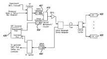
- FIG. 1shows a typical example of an RFoG network.
- video, and data modulated as AM-VSB and QAM RF Carriersis optically modulated by an optical transmitter, amplified in the optical domain by an erbium doped fiber amplifier (EDFA) and transported to the CPE at the subscriber site over fiber.
- EDFAerbium doped fiber amplifier
- the CPEconverts the optical signal into RF and the RF signals are delivered to the set top box and cable modem over coaxial cable.
- the signals carrying set top box data and upstream data from the cable modemare converted from an RF signal to an optical signal and transmitted to an optical receiver where they are converted back to RF and distributed to the upstream ports of the cable modem termination system (CMTS) and the set top box controller.
- CMTScable modem termination system
- the CMTS in the multiple system operator (MSO) headend, or hub and the cable modems at the subscriber sitesform a point to multi-point communication network.
- the RF carriers from the CMTSare continuously on.
- both Time Division Multiple Access (TDMA) and Frequency Division Multiple access (FDMA)are used.
- Multiple RF frequenciescan be assigned to groups of cables modems, and within a group of cable modems that use a specific RF frequency, TDMA is used to avoid data collisions. However any two (or more) cable modems that are operating at different RF frequencies can transmit at the same time.
- the lasers of the CPEs that they are connected toare also activated and there is a non-zero statistical probability that the laser wavelengths of those CPEs can overlap. It is critical to avoid this event in any RFoG system because when two (or more) optical signals of the same wavelength or with wavelengths that are close together are incident on an optical receiver, an optical effect known as Optical Beat Interference (OBI) can severely degrade of the signal-to-noise ratio (SNR) over a large RF bandwidth ( FIG. 2 ) resulting in a loss of data.
- OBIOptical Beat Interference
- CPE lasersoperate in a burst mode configuration. When the RF level of the upstream signal crosses a threshold level, the laser is turned on. When it drops below a certain threshold level, the laser is turned off. This burst mode operation reduces the probability of OBI, but does not eliminate it, as discussed above. In HFC networks, the upstream lasers are on continuously and therefore the probability of OBI is significantly higher.
- a methodcomprises: preventing optical beat interference including dynamically managing an adjustable optical transmitter wavelength of each of a plurality of customer premises equipment, wherein each of the plurality of customer premises equipment is in bidirectional communication with a customer premises equipment controller.
- an apparatuscomprises a bidirectional communication system including: a customer premises equipment controller; and a plurality of customer premises equipment coupled to the customer premises equipment controller, each of the plurality of customer premises equipment having an adjustable optical transmitter wavelength, wherein each of the plurality of customer premises equipment is in bidirectional communication with the customer premises equipment controller to prevent optical beat interference by dynamically managing the adjustable optical transmitter wavelength of each of the plurality of customer premises equipment.
- FIG. 1is a block schematic view of an RFoG network.
- FIG. 2shows spectrum analyzer traces of two 1550 nm lasers transmitters each modulated with a 256-QAM signal: a) SNR ratio without OBI is ⁇ 40 dB and b) SNR ratio with OBI ⁇ 10 dB.
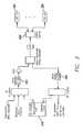
- FIG. 3is a block schematic view of an RFoG Network with a customer premises equipment and a customer premises equipment controller utilizing unique RF frequencies for downstream and upstream communication with the customer premises equipment.
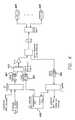
- FIG. 4is a block schematic view of an RFoG Network with the customer premises equipment controller downstream signal modulated on a separate optical transmitter.
- FIG. 5is a block schematic view of an RFoG customer premises equipment.
- FIG. 6is a view of a wavelength assignment process.
- Embodiments of this disclosureinclude methods, system architectures and apparatus to prevent OBI in RFoG networks or in hybrid fiber coax (HFC) networks, or in any other networks, where multiple laser transmitters can simultaneously operate over a common optical fiber connected to a shared optical receiver.
- the systemincludes a controller that resides in the headend or the hub, and a CPE that resides at the customer premises, as shown in FIG. 3 .
- the controller 310 and the CPEs 320form a bi-directional communication system. Downstream data messages from the controller are modulated on a RF carrier f1, optically modulated by the optical transmitter 330 , combined onto a single fiber and delivered to the CPE through the optical splitter 340 . Upstream data messages from the CPEs on f2 are delivered to the controller 310 through an optical receiver 350 .
- the optical signalis received by a photo diode 510 , amplified by an RF amplifier 520 , and delivered to a RF demodulator 530 through an RF splitter 540 .
- the RF demodulatorextracts the data stream and delivers it to the microcontroller 550 .
- control messages from the microcontrollerare modulated by an RF modulator 560 on an RF frequency f2.
- This RF carrieris modulated by the laser 570 and transmitted to the optical receiver 350 (shown in FIG. 3 ) through the optical diplexer 580 , the optical fiber and the wavelength division multiplexer (not shown in FIG. 5 ).
- two downstream optical transmitters 401 , 402are used.
- One transmitter 402is used to modulate the downstream RF signal from the controller.
- Another optical transmitter 401is used to modulate the downstream video, CMTS and set top box channels. These two transmitters operate at different optical wavelengths which are combined using an optical multiplexer 410 or an optical coupler. The combined signals are amplified, and delivered to the CPE 420 .
- the controller 430the optical transmitter 402 that modulates the downstream RF signal from the controller, and the optical receiver 440 to be located at the same location as the transmitter 401 that modulates the other downstream channels. They can be located at a remote location such as a node or a pedestal.
- a characteristic of a laseris that its wavelength can be adjusted by changing its DC bias point or its temperature.
- any given laser with intrinsic wavelength ⁇ i 0 at ambient temperaturecan access a range of wavelengths from ⁇ i _ min to ⁇ i _ max over temperature and bias current:
- ⁇ i ⁇ _ ⁇ ( min ⁇ ⁇ or ⁇ ⁇ max )⁇ i 0 + d ⁇ d T * ⁇ ⁇ ⁇ T - d ⁇ d I * ⁇ ⁇ ⁇ I
- T 0ambient temperature
- Ttemperature
- ⁇ i 0laser wavelength at ambient temperature
- I 0 (T)is laser bias current at given temperature for a particular output power
- the laser in the CPEis connected to a Thermo-Electric Cooler (TEC) that is used to change the temperature of the laser and thus its wavelength.
- TECThermo-Electric Cooler
- TECcan be mounted inside the laser.
- the systemworks by defining a wavelength grid.
- the gridcould include wavelength ranges, for example, known as the C-band, O-band or any CWDM wavelength band or combination of bands. It can also be defined to span the entire optical communication window from 1250 nm to 1650 nm.
- the rangeis specified by ⁇ start , ⁇ stop , and spacing between the wavelengths, ⁇ bin , is defined to be large enough to eliminate the possibility of OBI. Typically this is greater than 3 to 5 times the adiabatic chirp of the laser plus an additional amount to account for dynamic wavelength shift due to burst mode transmission and a margin for lifetime wavelength aging of a laser device.
- the TECis used to change the temperature of the laser and determine which wavelengths on the grid this particular laser can be tuned to. It should be noted that any one CPE may only map onto a very small subset of the M wavelengths on the grid. A table is created that contains the list of these wavelengths, and the corresponding temperature and TEC voltage that needs to be set to tune the laser to those wavelengths. The CPE then selects its default wavelength, which is the ideal wavelength it should be operated at. This wavelength would typically be in the middle of the range of wavelengths that a CPE laser can be tuned to.
- This information about the CPE default wavelengthis then stored into the memory of the CPE.
- This memorycan be an EEPROM, Flash, internal microcontroller memory, FPGA or any other method or device that can store information.
- the CPEWhen the CPE is first deployed in a network, it reports its default wavelength along with the number of wavelengths above and below the default wavelength that the CPE laser can be tuned to. Along with this information, the CPE also reports its unique identifier to the controller. This identifier can be a serial number, a MAC address, an IP address, or any other set of characters unique to the CPE. The controller compares this information to its database of information containing all the CPEs connected to that optical receiver. If the default wavelength of the new CPE has not been assigned to any other CPE on the same receiver, then the controller sends a downstream control message assigning the default wavelength to the CPE. The CPE continues to operate on this default wavelength unless told by the controller to move to a different wavelength.
- the controllerassigns to the CPE the closest available wavelength to its default wavelength. This ensures that as far as possible, the CPEs will operate at or close to their default wavelengths.
- FIG. 6shows how this process would work. Since CPE1 is the first CPE to come online, it is assigned its default wavelength ( ⁇ 5). CPEs 2, 3, and 4 also come online and are assigned their default wavelengths because those wavelengths have not been assigned to any other CPEs. CPE 5 comes online and its default wavelength is taken by CPE3, so CPE5 is assigned the next closest wavelength ( ⁇ 17) to right of the default wavelength. CPE7 also has the same default wavelength and it is assigned the wavelength to the left of its default wavelength ( ⁇ 15).
- the wavelength of the CPE laseris measured at two temperatures, T 1 and T 2 .
- the equationdefines the wavelength of the laser as a function of temperature.
- the two data points, the slope m and the constant bare stored in the CPEs memory.
- the CPEreports this information, along with its present operating wavelength and its unique identifier to the controller.
- the initial wavelength used by the CPE to report this informationcan be any wavelength that it can tune to.
- the controllercompares this information with its database of information on the wavelengths of all other CPEs connected to this optical receiver.
- a wavelength griddoes not have to be defined. It is also not necessary to limit the characterization of temperature and wavelength to two data points. An implementation with more data points will enable the wavelengths to be set more precisely.
- One factor that limits the operating temperature range of the CPEis the heating and cooling capacity of the TEC. Given this constraint, the following approach can be used to extend the operating temperature range of the CPE.
- One parameter the CPE could report to the controlleris its temperature.
- the controllercan collect the temperature readings from every CPE belonging to a single N sized cluster of CPEs connected to the optical receiver and can determine the distribution of temperatures for that specific cluster. There are daily and/or seasonal variations in ambient temperature and the controller can respond to the moving envelope of temperature variations.
- a cluster of CPEs connected to an optical receiveris likely confined to a geographic region where the CPEs would not experience both extremes of an industrial temperature range simultaneously. When the ambient temperature moves lower than the specified low operating temperature, the controller can move every CPE, in concert to a lower wavelength.
- the amount of wavelength shiftwould depend on the amount of change in the ambient temperature.
- the same approachcan be utilized to extend the operating temperature range on the high temperature side. This approach can also minimize the power consumption of the unit because at a lower ambient temperature, the TEC consumes less power to maintain wavelengths that are on the shorter side of the optical spectrum. Similarly, at higher ambient temperatures, the TEC consumes less power to maintain wavelengths that are on the longer side of the optical spectrum.
- the wavelength movementhappens in a way that the CPEs will not overlap when moved. For example when cold ambient temperatures are experienced the wavelengths will be moved to the shorter values starting from the shortest wavelength one-by-one to the longest wavelength. If the ambient temperatures move toward the hot extreme the wavelengths will be moved toward the higher values starting from the longest wavelength to the shortest.
- N CPEsIn a 1 ⁇ N network configuration, where N CPEs are connected to a single optical receiver, it is desirable to have N as large as possible.
- One factor that defines how large N can beis the variation in the intrinsic wavelengths of the lasers. If a group of CPEs use lasers manufactured from a single semiconductor wafer then the total available operating wavelength range for the group of lasers will be larger than the operating wavelength range of one laser from the wafer. This is because the laser chips on a wafer have a non-zero wavelength distribution. Typically the laser wavelengths across a single wafer follow a Gaussian distribution with a mean central wavelength of ⁇ 0 and standard deviation of ⁇ 1 nm.
- the laser transmittersare sourced from multiple wafers than the operating wavelength range could be even larger since the wafer-to-wafer mean wavelengths vary from run-to-run when comparing wafers manufactured from a single laser vendor.
- multi-sourced laser vendorsone could ensure a wide variation in intrinsic laser wavelengths.
- the decision of which laser in the array is turned oncan be done at initial startup and could be changed later as more CPEs come online and more usage statistics are gathered about the network of CPEs.
- the CPE wavelengthscan be moved into groups or clusters of high data bandwidth users and low data bandwidth users.
- the adjacent wavelength spacing criteria described abovecan be relaxed to allow more spectral bandwidth to be opened up for new CPEs as they are brought online. The relaxed criteria may only be needed when a new CPE that comes online cannot be assigned any of its accessible wavelengths because those wavelengths have been assigned to other CPEs.
- the two way communication channel between the controller and the CPEcan also be used to monitor wavelengths and periodic spectral position adjustments can be added to improve system performance.
- the improvementscould be in the form of relaxing the channel spacing for low bandwidth users or making corrections for aging of the laser. This could be done with an optical spectrum analyzer, an optical channel monitor or other wavelength monitoring device.
- the monitoring devicecould be shared within one group of N transmitters in a cluster or it could be shared among multiple groups of N sized clusters.
- Embodiments of the present disclosurecan include method and system architecture, and apparatus to prevent optical beat interference in optical networks that allow multiple laser transmitters to simultaneously transmit to a shared optical receiver.
- Embodiments of the present disclosurecan include a system that allows bi-directional communication path between the CPE and the controller over a downstream and an upstream RF frequency.
- Embodiments of the present disclosurecan include a system where the downstream RF frequency of the controller is modulated by a separate transmitter.
- Embodiments of the present disclosurecan include a CPE that stores laser wavelength information and determines its default wavelength from this information.
- Embodiments of the present disclosurecan include a CPE that transmits this information to the controller.
- Embodiments of the present disclosurecan include a controller that compares this information to the wavelength information from other CPEs and assigns to the CPE a wavelength such that OBI will not occur.
- Embodiments of the present disclosurecan include a CPE that receives downstream control messages from the controller carrying the wavelength assignment information, demodulates them, and based on this information uses a TEC to appropriately position its optical wavelength on the wavelength grid.
- Embodiments of the present disclosurecan include a method that uses information stored on the CPE about its laser transmitter wavelength characteristics and communicates it to the controller.
- Embodiments of the present disclosurecan include a method that uses the full spectral bandwidth of a laser transmitter to move it away from its default wavelength if needed.
- Embodiments of the present disclosurecan include a method that places CPE wavelengths into spectrally separated wavelength grid to prevent signal degradation from wavelength collisions of simultaneously transmitting CPEs.
- Embodiments of the present disclosurecan include a system that monitors CPE case temperatures and responds to daily and seasonal variations in temperature to extend the operational temperature range of the unit.
- Embodiments of the present disclosurecan include a method to widen the spectral bandwidth available to a CPE by employing an array of laser transmitters.
- Embodiments of the present disclosurecan include a method to employ custom semiconductor wafer fabrication to widen the wavelength distribution of laser transmitters available to a CPE.
- Embodiments of the present disclosurecan include a method that collects network data bandwidth usage statistics and moves CPE wavelengths into like-user clusters.
- Embodiments of the present disclosurecan include a system that employs wavelength monitoring to improve system performance.
- program and software and/or the phrases program elements, computer program and computer softwareare intended to mean a sequence of instructions designed for execution on a computer system (e.g., a program and/or computer program, may include a subroutine, a function, a procedure, an object method, an object implementation, an executable application, an applet, a servlet, a source code, an object code, a shared library/dynamic load library and/or other sequence of instructions designed for execution on a computer or computer system).
- RFradio frequency
- the phrase lightis intended to mean frequencies greater than or equal to approximately 300 GHz.
- the term uniformlyis intended to mean unvarying or deviate very little from a given and/or expected value (e.g., within 10% of).
- the term substantiallyis intended to mean largely but not necessarily wholly that which is specified.
- the term approximatelyis intended to mean at least close to a given value (e.g., within 10% of).
- the term generallyis intended to mean at least approaching a given state.
- the term coupledis intended to mean connected, although not necessarily directly, and not necessarily mechanically.
- proximateas used herein, is intended to mean close, near adjacent and/or coincident; and includes spatial situations where specified functions and/or results (if any) can be carried out and/or achieved.
- distalis intended to mean far, away, spaced apart from and/or non-coincident, and includes spatial situation where specified functions and/or results (if any) can be carried out and/or achieved.
- deployingis intended to mean designing, building, shipping, installing and/or operating.
- the terms first or one, and the phrases at least a first or at least one,are intended to mean the singular or the plural unless it is clear from the intrinsic text of this document that it is meant otherwise.
- the terms second or another, and the phrases at least a second or at least another,are intended to mean the singular or the plural unless it is clear from the intrinsic text of this document that it is meant otherwise.
- the terms a and/or anare employed for grammatical style and merely for convenience.
- the term pluralityis intended to mean two or more than two.
- the term anyis intended to mean all applicable members of a set or at least a subset of all applicable members of the set.
- the phrase any integer derivable thereinis intended to mean an integer between the corresponding numbers recited in the specification.
- the phrase any range derivable thereinis intended to mean any range within such corresponding numbers.
- the termmeans, when followed by the term “for” is intended to mean hardware, firmware and/or software for achieving a result.
- the term step, when followed by the term “for”is intended to mean a (sub)method, (sub)process and/or (sub)routine for achieving the recited result.
- all technical and scientific terms used hereinhave the same meaning as commonly understood by one of ordinary skill in the art to which this present disclosure belongs. In case of conflict, the present specification, including definitions, will control.
Landscapes
- Engineering & Computer Science (AREA)
- Signal Processing (AREA)
- Computer Networks & Wireless Communication (AREA)
- Physics & Mathematics (AREA)
- Electromagnetism (AREA)
- Computing Systems (AREA)
- Optics & Photonics (AREA)
- Optical Communication System (AREA)
Abstract
Description
where
ΔT=(Tmin−T0) and ΔI=(Imax−I0(T))
or
ΔT=(Tmax−T0) and ΔI=(Imin−I0(T))
T0=ambient temperature, T is temperature
λi
I0(T) is laser bias current at given temperature for a particular output power
is the change in laser wavelength as a function of temperature
is the change in laser wavelength as a function of laser bias current
λi=λstart+i*Δλbin
with i=0, 1, 2, 3 . . . M and λM≦λstop.
λk=m*Tk+b
m=(λ2−λ1)/(T2−T1)
Claims (13)
Priority Applications (2)
| Application Number | Priority Date | Filing Date | Title |
|---|---|---|---|
| US14/278,041US9577767B2 (en) | 2013-05-14 | 2014-05-15 | Dynamic wavelength management using bi-directional communication for the prevention of optical beat interference |
| US15/430,001US10476601B2 (en) | 2013-05-14 | 2017-02-10 | Dynamic wavelength management using bi-directional communication for the prevention of optical beat interference |
Applications Claiming Priority (2)
| Application Number | Priority Date | Filing Date | Title |
|---|---|---|---|
| US201361822992P | 2013-05-14 | 2013-05-14 | |
| US14/278,041US9577767B2 (en) | 2013-05-14 | 2014-05-15 | Dynamic wavelength management using bi-directional communication for the prevention of optical beat interference |
Related Child Applications (1)
| Application Number | Title | Priority Date | Filing Date |
|---|---|---|---|
| US15/430,001ContinuationUS10476601B2 (en) | 2013-05-14 | 2017-02-10 | Dynamic wavelength management using bi-directional communication for the prevention of optical beat interference |
Publications (2)
| Publication Number | Publication Date |
|---|---|
| US20140369689A1 US20140369689A1 (en) | 2014-12-18 |
| US9577767B2true US9577767B2 (en) | 2017-02-21 |
Family
ID=51265808
Family Applications (2)
| Application Number | Title | Priority Date | Filing Date |
|---|---|---|---|
| US14/278,041Expired - Fee RelatedUS9577767B2 (en) | 2013-05-14 | 2014-05-15 | Dynamic wavelength management using bi-directional communication for the prevention of optical beat interference |
| US15/430,001ActiveUS10476601B2 (en) | 2013-05-14 | 2017-02-10 | Dynamic wavelength management using bi-directional communication for the prevention of optical beat interference |
Family Applications After (1)
| Application Number | Title | Priority Date | Filing Date |
|---|---|---|---|
| US15/430,001ActiveUS10476601B2 (en) | 2013-05-14 | 2017-02-10 | Dynamic wavelength management using bi-directional communication for the prevention of optical beat interference |
Country Status (3)
| Country | Link |
|---|---|
| US (2) | US9577767B2 (en) |
| EP (1) | EP3008836B1 (en) |
| WO (1) | WO2014186505A1 (en) |
Cited By (1)
| Publication number | Priority date | Publication date | Assignee | Title |
|---|---|---|---|---|
| US20170155453A1 (en)* | 2013-05-14 | 2017-06-01 | Arris Enterprises Llc | Dynamic Wavelength Management using Bi-Directional Communication for the Prevention of Optical Beat Interference |
Families Citing this family (12)
| Publication number | Priority date | Publication date | Assignee | Title |
|---|---|---|---|---|
| EP3032861B1 (en)* | 2013-08-30 | 2018-01-10 | Huawei Technologies Co., Ltd. | Uplink signal transmission method, processing device and system |
| KR101925291B1 (en)* | 2013-12-02 | 2019-02-27 | 오이솔루션 아메리카 인코퍼레이티드 | Optical transceiver and optical communication system |
| US9705598B2 (en)* | 2014-04-03 | 2017-07-11 | Commscope, Inc. Of North Carolina | Methods and systems for reducing optical beat interference via polarization diversity in FTTx networks |
| US9590732B2 (en)* | 2014-04-21 | 2017-03-07 | Arris Enterprises, Inc. | Active optical combiner for CATV network |
| ES2745558T3 (en) | 2014-04-21 | 2020-03-02 | Arris Entpr Llc | Optical and RF techniques for aggregation of photodiode arrays |
| US9356726B2 (en)* | 2014-07-11 | 2016-05-31 | Aurora Networks, Inc. | Modulo channel assignment technique in optical point to multipoint networks to prevent optical beat interference |
| US9998235B2 (en) | 2016-01-08 | 2018-06-12 | Google Llc | In-band optical interference mitigation for direct-detection optical communication systems |
| US9847836B2 (en) | 2016-03-01 | 2017-12-19 | Arris Enterprises Llc | Agrregator-based cost-optimized communications topology for a point-to-multipoint network |
| US10200123B2 (en)* | 2016-06-20 | 2019-02-05 | Cable Television Laboratories, Inc. | System and methods for distribution of heterogeneous wavelength multiplexed signals over optical access network |
| US10397672B2 (en)* | 2016-06-20 | 2019-08-27 | Cable Television Laboratories, Inc. | Systems and methods for intelligent edge to edge optical system and wavelength provisioning |
| CN112448758B (en)* | 2019-09-03 | 2024-04-12 | 华为技术有限公司 | Wavelength adjusting method and related equipment |
| GB2608115A (en)* | 2021-06-21 | 2022-12-28 | Technetix Bv | Optical network device |
Citations (29)
| Publication number | Priority date | Publication date | Assignee | Title |
|---|---|---|---|---|
| US5880864A (en)* | 1996-05-30 | 1999-03-09 | Bell Atlantic Network Services, Inc. | Advanced optical fiber communications network |
| US6407843B1 (en) | 1998-03-05 | 2002-06-18 | Kestrel Solutions, Inc. | System and method for spectrally efficient transmission of digital data over optical fiber |
| US20020080444A1 (en) | 2000-12-22 | 2002-06-27 | David Phillips | Multiple access system for communications network |
| US20020186803A1 (en) | 2001-06-08 | 2002-12-12 | Kolze Thomas J. | Compensation of reference frequency drift in system requiring critical upstream timing |
| US6577414B1 (en) | 1998-02-20 | 2003-06-10 | Lucent Technologies Inc. | Subcarrier modulation fiber-to-the-home/curb (FTTH/C) access system providing broadband communications |
| US20030110509A1 (en) | 1999-12-13 | 2003-06-12 | Levinson Frank H. | Cable television return link system with high data-rate side-band communication channels |
| US6637033B1 (en) | 2000-07-10 | 2003-10-21 | Arris International, Inc. | Signal splitter and gain adjustment system for a cable data system |
| US20050012106A1 (en) | 2003-07-17 | 2005-01-20 | Fathimulla Ayub M. | Monolithic photoreceiver technology for free space optical networks |
| US20050025504A1 (en) | 2003-07-29 | 2005-02-03 | Harmonic Inc. | High dynamic range optical receiver |
| US20050025485A1 (en) | 2003-07-30 | 2005-02-03 | Ki-Cheol Lee | Subscriber interfacing device in communication-broadcasting convergence FTTH |
| US20050047442A1 (en) | 2003-08-25 | 2005-03-03 | Brady Volpe | Method and apparatus for collectively and selectively analyzing the signal integrity of individual cable modems on a DOCSIS network |
| US20050078958A1 (en) | 2001-08-10 | 2005-04-14 | Chang-Joon Chae | Optical csma/cd technique |
| US20050172328A1 (en) | 2004-01-30 | 2005-08-04 | Se-Hong Park | FTTH system based on passive optical network for broadcasting service |
| US20060098697A1 (en) | 2004-11-08 | 2006-05-11 | Kim Byoung W | Wavelength tunable light source module for wavelength division multiplexing passive optical network system |
| US20060115271A1 (en) | 2004-11-29 | 2006-06-01 | Samsung Electronics Co., Ltd. | Method for operating wavelength-division-multiplexed passive optical network |
| US20070058989A1 (en) | 2005-09-09 | 2007-03-15 | Shinkyo Kaku | In-situ power monitor providing an extended range for monitoring input optical power incident on avalanche photodiodes |
| US20070183738A1 (en) | 2001-10-09 | 2007-08-09 | Infinera Corporation | Monolithic photonic integrated circuit (pic) with forward error correction (fec) |
| US20070264021A1 (en)* | 2006-04-28 | 2007-11-15 | Wen Li | High-speed fiber-to-the-premise optical communication system |
| US20080085118A1 (en)* | 2006-10-04 | 2008-04-10 | Futurewei Technologies, Inc. | High Capacity Optical Frequency Division Multiple Access Passive Optical Network |
| US20080101801A1 (en) | 2006-11-01 | 2008-05-01 | General Instrument Corporation | Small Form Pluggable Analog Optical Transmitter |
| US20080232801A1 (en) | 2007-03-20 | 2008-09-25 | Erich Arnold | Method and system for transporting docsis communication signals over a passive optical network |
| US20090041459A1 (en) | 2002-11-05 | 2009-02-12 | Dress William B | Optical fan-out and broadcast interconnect methodology |
| US20090317091A1 (en) | 2008-06-24 | 2009-12-24 | Mark Vogel | Laser transmitting at automatically varying wavelengths, network interface unit and system including the laser, and method of automatically varying the wavelength of a laser |
| US20100220994A1 (en) | 2009-02-18 | 2010-09-02 | Krzysztof Pradzynski | Self-correcting wavelength collision avoidance system |
| US20110135309A1 (en)* | 2009-12-08 | 2011-06-09 | Electronics And Telecommunications Research Institute | Wavelength division multiplexing-passive optical network (wdm-pon) |
| US20120057875A1 (en)* | 2010-09-07 | 2012-03-08 | Infinera Corporation | Wavelength division multiplexed passive optical network |
| US20120183297A1 (en)* | 2009-08-21 | 2012-07-19 | Nokia Siemens Networks Oy | Method and device for adjusting a laser in an optical network |
| WO2013016450A1 (en) | 2011-07-25 | 2013-01-31 | Aurora Networks, Inc. | Rfog cpe devices with wavelength collision avoidance using laser transmitter local and/or remote tunability |
| US20130279914A1 (en)* | 2012-04-19 | 2013-10-24 | Paul D. Brooks | Apparatus and methods for dynamic delivery of optical and non-optical content in a network |
Family Cites Families (1)
| Publication number | Priority date | Publication date | Assignee | Title |
|---|---|---|---|---|
| WO2014186505A1 (en)* | 2013-05-14 | 2014-11-20 | Aurora Networks, Inc. | Dynamic wavelength management using bi-directional communication for the prevention of optical beat interference |
- 2014
- 2014-05-15WOPCT/US2014/038068patent/WO2014186505A1/enactiveApplication Filing
- 2014-05-15USUS14/278,041patent/US9577767B2/ennot_activeExpired - Fee Related
- 2014-05-15EPEP14747427.4Apatent/EP3008836B1/enactiveActive
- 2017
- 2017-02-10USUS15/430,001patent/US10476601B2/enactiveActive
Patent Citations (29)
| Publication number | Priority date | Publication date | Assignee | Title |
|---|---|---|---|---|
| US5880864A (en)* | 1996-05-30 | 1999-03-09 | Bell Atlantic Network Services, Inc. | Advanced optical fiber communications network |
| US6577414B1 (en) | 1998-02-20 | 2003-06-10 | Lucent Technologies Inc. | Subcarrier modulation fiber-to-the-home/curb (FTTH/C) access system providing broadband communications |
| US6407843B1 (en) | 1998-03-05 | 2002-06-18 | Kestrel Solutions, Inc. | System and method for spectrally efficient transmission of digital data over optical fiber |
| US20030110509A1 (en) | 1999-12-13 | 2003-06-12 | Levinson Frank H. | Cable television return link system with high data-rate side-band communication channels |
| US6637033B1 (en) | 2000-07-10 | 2003-10-21 | Arris International, Inc. | Signal splitter and gain adjustment system for a cable data system |
| US20020080444A1 (en) | 2000-12-22 | 2002-06-27 | David Phillips | Multiple access system for communications network |
| US20020186803A1 (en) | 2001-06-08 | 2002-12-12 | Kolze Thomas J. | Compensation of reference frequency drift in system requiring critical upstream timing |
| US20050078958A1 (en) | 2001-08-10 | 2005-04-14 | Chang-Joon Chae | Optical csma/cd technique |
| US20070183738A1 (en) | 2001-10-09 | 2007-08-09 | Infinera Corporation | Monolithic photonic integrated circuit (pic) with forward error correction (fec) |
| US20090041459A1 (en) | 2002-11-05 | 2009-02-12 | Dress William B | Optical fan-out and broadcast interconnect methodology |
| US20050012106A1 (en) | 2003-07-17 | 2005-01-20 | Fathimulla Ayub M. | Monolithic photoreceiver technology for free space optical networks |
| US20050025504A1 (en) | 2003-07-29 | 2005-02-03 | Harmonic Inc. | High dynamic range optical receiver |
| US20050025485A1 (en) | 2003-07-30 | 2005-02-03 | Ki-Cheol Lee | Subscriber interfacing device in communication-broadcasting convergence FTTH |
| US20050047442A1 (en) | 2003-08-25 | 2005-03-03 | Brady Volpe | Method and apparatus for collectively and selectively analyzing the signal integrity of individual cable modems on a DOCSIS network |
| US20050172328A1 (en) | 2004-01-30 | 2005-08-04 | Se-Hong Park | FTTH system based on passive optical network for broadcasting service |
| US20060098697A1 (en) | 2004-11-08 | 2006-05-11 | Kim Byoung W | Wavelength tunable light source module for wavelength division multiplexing passive optical network system |
| US20060115271A1 (en) | 2004-11-29 | 2006-06-01 | Samsung Electronics Co., Ltd. | Method for operating wavelength-division-multiplexed passive optical network |
| US20070058989A1 (en) | 2005-09-09 | 2007-03-15 | Shinkyo Kaku | In-situ power monitor providing an extended range for monitoring input optical power incident on avalanche photodiodes |
| US20070264021A1 (en)* | 2006-04-28 | 2007-11-15 | Wen Li | High-speed fiber-to-the-premise optical communication system |
| US20080085118A1 (en)* | 2006-10-04 | 2008-04-10 | Futurewei Technologies, Inc. | High Capacity Optical Frequency Division Multiple Access Passive Optical Network |
| US20080101801A1 (en) | 2006-11-01 | 2008-05-01 | General Instrument Corporation | Small Form Pluggable Analog Optical Transmitter |
| US20080232801A1 (en) | 2007-03-20 | 2008-09-25 | Erich Arnold | Method and system for transporting docsis communication signals over a passive optical network |
| US20090317091A1 (en) | 2008-06-24 | 2009-12-24 | Mark Vogel | Laser transmitting at automatically varying wavelengths, network interface unit and system including the laser, and method of automatically varying the wavelength of a laser |
| US20100220994A1 (en) | 2009-02-18 | 2010-09-02 | Krzysztof Pradzynski | Self-correcting wavelength collision avoidance system |
| US20120183297A1 (en)* | 2009-08-21 | 2012-07-19 | Nokia Siemens Networks Oy | Method and device for adjusting a laser in an optical network |
| US20110135309A1 (en)* | 2009-12-08 | 2011-06-09 | Electronics And Telecommunications Research Institute | Wavelength division multiplexing-passive optical network (wdm-pon) |
| US20120057875A1 (en)* | 2010-09-07 | 2012-03-08 | Infinera Corporation | Wavelength division multiplexed passive optical network |
| WO2013016450A1 (en) | 2011-07-25 | 2013-01-31 | Aurora Networks, Inc. | Rfog cpe devices with wavelength collision avoidance using laser transmitter local and/or remote tunability |
| US20130279914A1 (en)* | 2012-04-19 | 2013-10-24 | Paul D. Brooks | Apparatus and methods for dynamic delivery of optical and non-optical content in a network |
Non-Patent Citations (4)
| Title |
|---|
| International Preliminary Report on Patentability from PCT/US20141038068, Nov. 26, 2015. |
| International search report and the written opinion of the international searching authority, PCT/US2010/000962, dated May 19, 2010. |
| International Search Report and Written Opinion form PCT/2014/038068 dated Oct. 20, 2014. |
| International Search Report and Written Opinion from PCT/US2014/038068, Oct. 20, 2014. |
Cited By (2)
| Publication number | Priority date | Publication date | Assignee | Title |
|---|---|---|---|---|
| US20170155453A1 (en)* | 2013-05-14 | 2017-06-01 | Arris Enterprises Llc | Dynamic Wavelength Management using Bi-Directional Communication for the Prevention of Optical Beat Interference |
| US10476601B2 (en)* | 2013-05-14 | 2019-11-12 | Arris Solutions, Inc. | Dynamic wavelength management using bi-directional communication for the prevention of optical beat interference |
Also Published As
| Publication number | Publication date |
|---|---|
| EP3008836B1 (en) | 2019-07-24 |
| US20140369689A1 (en) | 2014-12-18 |
| EP3008836A1 (en) | 2016-04-20 |
| US20170155453A1 (en) | 2017-06-01 |
| US10476601B2 (en) | 2019-11-12 |
| WO2014186505A1 (en) | 2014-11-20 |
Similar Documents
| Publication | Publication Date | Title |
|---|---|---|
| US10476601B2 (en) | Dynamic wavelength management using bi-directional communication for the prevention of optical beat interference | |
| US7450848B2 (en) | High-speed fiber-to-the-premise optical communication system | |
| US11876560B2 (en) | System and methods for distribution of heterogeneous wavelength multiplexed signals over optical access network | |
| Bindhaiq et al. | Recent development on time and wavelength-division multiplexed passive optical network (TWDM-PON) for next-generation passive optical network stage 2 (NG-PON2) | |
| US7317874B2 (en) | Adaptive optical transceiver for fiber access communications | |
| Nesset | NG-PON2 technology and standards | |
| US8649681B2 (en) | Methods and devices for wavelength alignment in WDM-PON | |
| US8126332B2 (en) | Method of wavelength alignment for a wavelength division multiplexed passive optical network | |
| US20080089699A1 (en) | Methods for automatic tuning optical communication system | |
| KR101471688B1 (en) | Periodically filtered broadband light source | |
| US9173013B2 (en) | Method and device for adjusting a laser in an optical network | |
| Sales et al. | Statistical UDWDM-PONs operating with ONU lasers under limited tunability | |
| CN105763282B (en) | A kind of wavelength control method and its device of adjustable ONU in PON system | |
| Suzuki et al. | Wavelength-tunable DWDM-SFP transceiver with a signal monitoring interface and its application to coexistence-type colorless WDM-PON | |
| CN101426154B (en) | Outer cavity laser capable of being used as WDM-PON | |
| JP5786471B2 (en) | Optical communication device | |
| CA2911944C (en) | Dynamic wavelength management using bi-directional communication for the prevention of optical beat interference | |
| US20100254708A1 (en) | Laser wavelength stabilization | |
| Lee et al. | First commercial service of a colorless gigabit WDM/TDM hybrid PON system | |
| KR100860548B1 (en) | Wavelength tracking system using self-locking, wavelength division multiplexing passive optical communication system and wavelength tracking method including the same | |
| Shin et al. | NG-PON2 Development for 10G Internet Service: A Study Case of SK | |
| Segarra et al. | Grade of service in UDWDM-PON with statistical wavelength subscribing | |
| Xu et al. | Investigation of wavelength-tunable directly-modulated laser for 100-Gb/s EPON | |
| Cheng et al. | Trunk fiber sharing for CO consolidation using dynamic spectrum management | |
| KR20150051856A (en) | Method for measuring wavelength tuning time of tunable devices in an optical network and the apparatus thereof |
Legal Events
| Date | Code | Title | Description |
|---|---|---|---|
| AS | Assignment | Owner name:AURORA NETWORKS, INC., CALIFORNIA Free format text:ASSIGNMENT OF ASSIGNORS INTEREST;ASSIGNORS:GADKARI, KETAN;MORBI, ZULFIKAR;REJALY, DARYOOSH;AND OTHERS;REEL/FRAME:033624/0910 Effective date:20140825 | |
| AS | Assignment | Owner name:BANK OF AMERICA, N.A., ILLINOIS Free format text:SECURITY INTEREST;ASSIGNORS:ARRIS GLOBAL LIMITED F/K/A PACE PLC;2WIRE, INC.;AURORA NETWORKS, INC.;REEL/FRAME:040054/0001 Effective date:20160830 | |
| STCF | Information on status: patent grant | Free format text:PATENTED CASE | |
| AS | Assignment | Owner name:ARRIS GLOBAL LIMITED, F/K/A PACE PLC, PENNSYLVANIA Free format text:TERMINATION AND RELEASE OF SECURITY INTEREST IN PATENTS;ASSIGNOR:BANK OF AMERICA, N.A., AS ADMINISTRATIVE AGENT;REEL/FRAME:048817/0496 Effective date:20190404 Owner name:2WIRE, INC., CALIFORNIA Free format text:TERMINATION AND RELEASE OF SECURITY INTEREST IN PATENTS;ASSIGNOR:BANK OF AMERICA, N.A., AS ADMINISTRATIVE AGENT;REEL/FRAME:048817/0496 Effective date:20190404 Owner name:AURORA NETWORKS, INC., CALIFORNIA Free format text:TERMINATION AND RELEASE OF SECURITY INTEREST IN PATENTS;ASSIGNOR:BANK OF AMERICA, N.A., AS ADMINISTRATIVE AGENT;REEL/FRAME:048817/0496 Effective date:20190404 | |
| AS | Assignment | Owner name:ARRIS SOLUTIONS, INC., PENNSYLVANIA Free format text:MERGER;ASSIGNOR:AURORA NETWORKS, INC.;REEL/FRAME:049586/0627 Effective date:20170101 | |
| AS | Assignment | Owner name:WILMINGTON TRUST, NATIONAL ASSOCIATION, AS COLLATE Free format text:PATENT SECURITY AGREEMENT;ASSIGNOR:ARRIS SOLUTIONS, INC.;REEL/FRAME:049678/0398 Effective date:20190404 Owner name:JPMORGAN CHASE BANK, N.A., NEW YORK Free format text:ABL SECURITY AGREEMENT;ASSIGNORS:COMMSCOPE, INC. OF NORTH CAROLINA;COMMSCOPE TECHNOLOGIES LLC;ARRIS ENTERPRISES LLC;AND OTHERS;REEL/FRAME:049892/0396 Effective date:20190404 Owner name:JPMORGAN CHASE BANK, N.A., NEW YORK Free format text:TERM LOAN SECURITY AGREEMENT;ASSIGNORS:COMMSCOPE, INC. OF NORTH CAROLINA;COMMSCOPE TECHNOLOGIES LLC;ARRIS ENTERPRISES LLC;AND OTHERS;REEL/FRAME:049905/0504 Effective date:20190404 | |
| MAFP | Maintenance fee payment | Free format text:PAYMENT OF MAINTENANCE FEE, 4TH YEAR, LARGE ENTITY (ORIGINAL EVENT CODE: M1551); ENTITY STATUS OF PATENT OWNER: LARGE ENTITY Year of fee payment:4 | |
| AS | Assignment | Owner name:WILMINGTON TRUST, DELAWARE Free format text:SECURITY INTEREST;ASSIGNORS:ARRIS SOLUTIONS, INC.;ARRIS ENTERPRISES LLC;COMMSCOPE TECHNOLOGIES LLC;AND OTHERS;REEL/FRAME:060752/0001 Effective date:20211115 | |
| AS | Assignment | Owner name:ARRIS SOLUTIONS LLC, DELAWARE Free format text:CHANGE OF NAME;ASSIGNOR:ARRIS SOLUTIONS, INC.;REEL/FRAME:065244/0841 Effective date:20231010 | |
| AS | Assignment | Owner name:ARRIS ENTERPRISES LLC, PENNSYLVANIA Free format text:ASSIGNMENT OF ASSIGNORS INTEREST;ASSIGNOR:ARRIS SOLUTIONS LLC;REEL/FRAME:065880/0152 Effective date:20231201 | |
| FEPP | Fee payment procedure | Free format text:MAINTENANCE FEE REMINDER MAILED (ORIGINAL EVENT CODE: REM.); ENTITY STATUS OF PATENT OWNER: LARGE ENTITY | |
| AS | Assignment | Owner name:APOLLO ADMINISTRATIVE AGENCY LLC, NEW YORK Free format text:SECURITY INTEREST;ASSIGNORS:ARRIS ENTERPRISES LLC;COMMSCOPE TECHNOLOGIES LLC;COMMSCOPE INC., OF NORTH CAROLINA;AND OTHERS;REEL/FRAME:069889/0114 Effective date:20241217 | |
| AS | Assignment | Owner name:RUCKUS WIRELESS, LLC (F/K/A RUCKUS WIRELESS, INC.), NORTH CAROLINA Free format text:RELEASE OF SECURITY INTEREST AT REEL/FRAME 049905/0504;ASSIGNOR:JPMORGAN CHASE BANK, N.A., AS COLLATERAL AGENT;REEL/FRAME:071477/0255 Effective date:20241217 Owner name:COMMSCOPE TECHNOLOGIES LLC, NORTH CAROLINA Free format text:RELEASE OF SECURITY INTEREST AT REEL/FRAME 049905/0504;ASSIGNOR:JPMORGAN CHASE BANK, N.A., AS COLLATERAL AGENT;REEL/FRAME:071477/0255 Effective date:20241217 Owner name:COMMSCOPE, INC. OF NORTH CAROLINA, NORTH CAROLINA Free format text:RELEASE OF SECURITY INTEREST AT REEL/FRAME 049905/0504;ASSIGNOR:JPMORGAN CHASE BANK, N.A., AS COLLATERAL AGENT;REEL/FRAME:071477/0255 Effective date:20241217 Owner name:ARRIS SOLUTIONS, INC., NORTH CAROLINA Free format text:RELEASE OF SECURITY INTEREST AT REEL/FRAME 049905/0504;ASSIGNOR:JPMORGAN CHASE BANK, N.A., AS COLLATERAL AGENT;REEL/FRAME:071477/0255 Effective date:20241217 Owner name:ARRIS TECHNOLOGY, INC., NORTH CAROLINA Free format text:RELEASE OF SECURITY INTEREST AT REEL/FRAME 049905/0504;ASSIGNOR:JPMORGAN CHASE BANK, N.A., AS COLLATERAL AGENT;REEL/FRAME:071477/0255 Effective date:20241217 Owner name:ARRIS ENTERPRISES LLC (F/K/A ARRIS ENTERPRISES, INC.), NORTH CAROLINA Free format text:RELEASE OF SECURITY INTEREST AT REEL/FRAME 049905/0504;ASSIGNOR:JPMORGAN CHASE BANK, N.A., AS COLLATERAL AGENT;REEL/FRAME:071477/0255 Effective date:20241217 | |
| LAPS | Lapse for failure to pay maintenance fees | Free format text:PATENT EXPIRED FOR FAILURE TO PAY MAINTENANCE FEES (ORIGINAL EVENT CODE: EXP.); ENTITY STATUS OF PATENT OWNER: LARGE ENTITY | |
| STCH | Information on status: patent discontinuation | Free format text:PATENT EXPIRED DUE TO NONPAYMENT OF MAINTENANCE FEES UNDER 37 CFR 1.362 | |
| FP | Lapsed due to failure to pay maintenance fee | Effective date:20250221 |