US9575894B1 - Application aware cache coherency - Google Patents
Application aware cache coherencyDownload PDFInfo
- Publication number
- US9575894B1 US9575894B1US14/670,544US201514670544AUS9575894B1US 9575894 B1US9575894 B1US 9575894B1US 201514670544 AUS201514670544 AUS 201514670544AUS 9575894 B1US9575894 B1US 9575894B1
- Authority
- US
- United States
- Prior art keywords
- site
- cache
- storage
- processor
- cache storage
- Prior art date
- Legal status (The legal status is an assumption and is not a legal conclusion. Google has not performed a legal analysis and makes no representation as to the accuracy of the status listed.)
- Active
Links
Images


Classifications
- G—PHYSICS
- G06—COMPUTING OR CALCULATING; COUNTING
- G06F—ELECTRIC DIGITAL DATA PROCESSING
- G06F12/00—Accessing, addressing or allocating within memory systems or architectures
- G06F12/02—Addressing or allocation; Relocation
- G06F12/08—Addressing or allocation; Relocation in hierarchically structured memory systems, e.g. virtual memory systems
- G06F12/0802—Addressing of a memory level in which the access to the desired data or data block requires associative addressing means, e.g. caches
- G06F12/0806—Multiuser, multiprocessor or multiprocessing cache systems
- G06F12/0815—Cache consistency protocols
- G06F12/0831—Cache consistency protocols using a bus scheme, e.g. with bus monitoring or watching means
- G06F12/0833—Cache consistency protocols using a bus scheme, e.g. with bus monitoring or watching means in combination with broadcast means (e.g. for invalidation or updating)
- G—PHYSICS
- G06—COMPUTING OR CALCULATING; COUNTING
- G06F—ELECTRIC DIGITAL DATA PROCESSING
- G06F3/00—Input arrangements for transferring data to be processed into a form capable of being handled by the computer; Output arrangements for transferring data from processing unit to output unit, e.g. interface arrangements
- G06F3/06—Digital input from, or digital output to, record carriers, e.g. RAID, emulated record carriers or networked record carriers
- G06F3/0601—Interfaces specially adapted for storage systems
- G06F3/0602—Interfaces specially adapted for storage systems specifically adapted to achieve a particular effect
- G06F3/0614—Improving the reliability of storage systems
- G06F3/0619—Improving the reliability of storage systems in relation to data integrity, e.g. data losses, bit errors
- G—PHYSICS
- G06—COMPUTING OR CALCULATING; COUNTING
- G06F—ELECTRIC DIGITAL DATA PROCESSING
- G06F12/00—Accessing, addressing or allocating within memory systems or architectures
- G06F12/02—Addressing or allocation; Relocation
- G06F12/08—Addressing or allocation; Relocation in hierarchically structured memory systems, e.g. virtual memory systems
- G06F12/12—Replacement control
- G06F12/121—Replacement control using replacement algorithms
- G06F12/128—Replacement control using replacement algorithms adapted to multidimensional cache systems, e.g. set-associative, multicache, multiset or multilevel
- G—PHYSICS
- G06—COMPUTING OR CALCULATING; COUNTING
- G06F—ELECTRIC DIGITAL DATA PROCESSING
- G06F3/00—Input arrangements for transferring data to be processed into a form capable of being handled by the computer; Output arrangements for transferring data from processing unit to output unit, e.g. interface arrangements
- G06F3/06—Digital input from, or digital output to, record carriers, e.g. RAID, emulated record carriers or networked record carriers
- G06F3/0601—Interfaces specially adapted for storage systems
- G06F3/0628—Interfaces specially adapted for storage systems making use of a particular technique
- G06F3/0646—Horizontal data movement in storage systems, i.e. moving data in between storage devices or systems
- G06F3/0647—Migration mechanisms
- G—PHYSICS
- G06—COMPUTING OR CALCULATING; COUNTING
- G06F—ELECTRIC DIGITAL DATA PROCESSING
- G06F3/00—Input arrangements for transferring data to be processed into a form capable of being handled by the computer; Output arrangements for transferring data from processing unit to output unit, e.g. interface arrangements
- G06F3/06—Digital input from, or digital output to, record carriers, e.g. RAID, emulated record carriers or networked record carriers
- G06F3/0601—Interfaces specially adapted for storage systems
- G06F3/0628—Interfaces specially adapted for storage systems making use of a particular technique
- G06F3/0662—Virtualisation aspects
- G06F3/0665—Virtualisation aspects at area level, e.g. provisioning of virtual or logical volumes
- G—PHYSICS
- G06—COMPUTING OR CALCULATING; COUNTING
- G06F—ELECTRIC DIGITAL DATA PROCESSING
- G06F3/00—Input arrangements for transferring data to be processed into a form capable of being handled by the computer; Output arrangements for transferring data from processing unit to output unit, e.g. interface arrangements
- G06F3/06—Digital input from, or digital output to, record carriers, e.g. RAID, emulated record carriers or networked record carriers
- G06F3/0601—Interfaces specially adapted for storage systems
- G06F3/0668—Interfaces specially adapted for storage systems adopting a particular infrastructure
- G06F3/067—Distributed or networked storage systems, e.g. storage area networks [SAN], network attached storage [NAS]
- G—PHYSICS
- G06—COMPUTING OR CALCULATING; COUNTING
- G06F—ELECTRIC DIGITAL DATA PROCESSING
- G06F3/00—Input arrangements for transferring data to be processed into a form capable of being handled by the computer; Output arrangements for transferring data from processing unit to output unit, e.g. interface arrangements
- G06F3/06—Digital input from, or digital output to, record carriers, e.g. RAID, emulated record carriers or networked record carriers
- G06F3/0601—Interfaces specially adapted for storage systems
- G06F3/0668—Interfaces specially adapted for storage systems adopting a particular infrastructure
- G06F3/0671—In-line storage system
- G06F3/0683—Plurality of storage devices
- G06F3/0688—Non-volatile semiconductor memory arrays
- G—PHYSICS
- G06—COMPUTING OR CALCULATING; COUNTING
- G06F—ELECTRIC DIGITAL DATA PROCESSING
- G06F3/00—Input arrangements for transferring data to be processed into a form capable of being handled by the computer; Output arrangements for transferring data from processing unit to output unit, e.g. interface arrangements
- G06F3/06—Digital input from, or digital output to, record carriers, e.g. RAID, emulated record carriers or networked record carriers
- G06F3/0601—Interfaces specially adapted for storage systems
- G06F3/0668—Interfaces specially adapted for storage systems adopting a particular infrastructure
- G06F3/0671—In-line storage system
- G06F3/0683—Plurality of storage devices
- G06F3/0689—Disk arrays, e.g. RAID, JBOD
- G—PHYSICS
- G06—COMPUTING OR CALCULATING; COUNTING
- G06F—ELECTRIC DIGITAL DATA PROCESSING
- G06F2212/00—Indexing scheme relating to accessing, addressing or allocation within memory systems or architectures
- G06F2212/62—Details of cache specific to multiprocessor cache arrangements
- G06F2212/69—
Definitions
- This applicationis related to the field of data storage and, particularly, to systems for managing data and resources in a virtualized environment.
- a virtual machineis a software implementation of a machine that executes programs like a physical machine. Virtualization software allows multiple VMs with separate operating systems to run in isolation on the same physical server. Each VM may have its own set of virtual hardware (e.g., RAM, CPU, NIC, etc.) upon which an operating system and applications are loaded. The operating system may see a consistent, normalized set of hardware regardless of the actual physical hardware components.
- a virtual centermay operate to control virtual machines in data centers and, for example, in connection with cloud computing. The virtual center may further include a virtual data center that provides logical control and management of data storage in a data center, and provides for sub-dividing contents of virtual components into compute resources, network resources and storage resources.
- VMsConfiguring and deploying VMs is known in the field of computer science.
- VMsmay be provisioned with respect to any appropriate resource, including, for example, storage resources, CPU processing resources and/or memory. Operations of VMs may include using virtual machine images.
- a VMthat may be moved between different locations and processing thereafter continued without interruption.
- U.S. Pat. No. 8,667,490 B1 to van der Gootentitled “Active/Active Storage and Virtual Machine Mobility Over Asynchronous Distances,” which is incorporated herein by reference.
- cache coherencymay provide cached data consistency, data access efficiency may suffer if a process on a first site needs to access cached data on a second site. Accordingly, it would be desirable to provide a system that addresses the above-noted problems and efficiently and effectively provides for handling cached data for a process that is moved from one site to another.
- a distributed processing systemincludes a first site containing at least one device having cache storage, nonvolatile storage, and at least one processor that accesses the storage of the first site and a second site, coupled to the first site, containing at least one device having cache storage, nonvolatile storage, and at least one processor that accesses the storage of the second site, where, in response to moving a process running on the processor of the first site to the processor running on the second site, data in the cache storage of the first site is no longer accessed by the process, the data being read into the cache of the storage of the first site in response to the process accessing data in the non-volatile memory of the first site prior to being moved to the second site.
- Data in the cache storage of the first site no longer being accessedmay include destaging data that had been modified by the process after being read into the cache of the first site and may include removing any remaining data from the cache of the first site.
- Data in the cache storage of the first site no longer being accessedmay include transferring data from the cache of the first site to the cache of the second site. Data that is transferred from the cache of the first site to the cache of the second site may be deleted from the cache of the first site after the transfer.
- the portion of the datamay be transferred to the cache in the second site prior to being accessed by the process.
- the portion of the datamay be destaged to non-volatile storage in connection with transferring the portion of the data.
- Each of the sitesmay include at least one host processing device and at least one disk array storage device and the process may run on at least one of the hosts.
- a process running on the processor of the first site moving to the processor running on the second site and corresponding cache slotsmay be detected by parsing the VMFS containing virtual machine disks used by the process.
- managing a distributed processing systemincludes providing a first site containing at least one device having cache storage, nonvolatile storage, and at least one processor that accesses the storage of the first site, providing a second site, coupled to the first site, containing at least one device having cache storage, nonvolatile storage, and at least one processor that accesses the storage of the second site, moving a process running on the processor of the first site to the processor running on the second site, and causing data in the cache storage of the first site to no longer be accessed by the process, the data being read into the cache of the storage of the first site in response to the process accessing data in the non-volatile memory of the first site prior to being moved to the second site.
- Causing data in the cache storage of the first site to no longer be accessedmay include destaging data that had been modified by the process after being read into the cache of the first site and may include removing any remaining data from the cache of the first site.
- Causing data in the cache storage of the first site to no longer be accessedmay include transferring data from the cache of the first site to the cache of the second site. Data that is transferred from the cache of the first site to the cache of the second site may be deleted from the cache of the first site after the transfer.
- the portion of the datamay be transferred to the cache in the second site prior to being accessed by the process.
- the portion of the datamay be destaged to non-volatile storage in connection with transferring the portion of the data.
- a process running on the processor of the first site moving to the processor running on the second site and corresponding cache slotsmay be detected by parsing the VMFS containing virtual machine disks used by the process.
- a non-transitory computer-readable medium containing software that manages a distributed processing systemhas a first site containing at least one device having cache storage, nonvolatile storage, and at least one processor that accesses the storage of the first site and a second site, coupled to the first site, containing at least one device having cache storage, nonvolatile storage, and at least one processor that accesses the storage of the second site.
- the softwareincludes executable code that moves a process running on the processor of the first site to the processor running on the second site and executable code that causes data in the cache storage of the first site to no longer be accessed by the process, the data being read into the cache of the storage of the first site in response to the process accessing data in the non-volatile memory of the first site prior to being moved to the second site.
- Causing data in the cache storage of the first site to no longer be accessedmay include destaging data that had been modified by the process after being read into the cache of the first site and may include removing any remaining data from the cache of the first site.
- Causing data in the cache storage of the first site to no longer be accessedmay include transferring data from the cache of the first site to the cache of the second site.
- Data that is transferred from the cache of the first site to the cache of the second sitemay be deleted from the cache of the first site after the transfer.
- a process running on the processor of the first site moving to the processor running on the second site and corresponding cache slotsmay be detected by parsing the VMFS containing virtual machine disks used by the process.
- FIG. 1shows a network configuration of a distributed storage system that may be used in accordance with an embodiment of the system described herein.
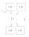
- FIG. 2is a schematic illustration showing a system that includes a plurality of data centers in communication via a network that may be used in accordance with an embodiment of the system described herein.
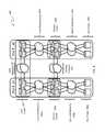
- FIG. 3is a schematic illustration showing a distributed storage system with multiple sites according to an embodiment of the system described herein.
- FIGS. 4 and 5show alternative configurations of distributed storage systems that may be used in accordance with embodiments of the system described herein.
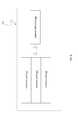
- FIG. 6shows an exemplary cloud computing system that may be used in connection with various embodiments of the system described herein in a manner similar to that discussed herein in connection with other types of distributed processing systems.
- FIG. 7is a flow diagram illustrating processing performed in connection with handling cached data for processes that have been moved, according to an embodiment of the system described herein.
- FIG. 8is a flow diagram illustrating processing performed in connection with removing cached data from an originating location according to an embodiment of the system described herein.
- FIG. 9is a flow diagram illustrating processing performed in connection with transferring cache slots from an originating location to a destination location according to an embodiment of the system described herein.
- FIG. 10is a flow diagram illustrating processing performed in connection with accessing a cache slot in a process according to an embodiment of the system described herein.
- FIG. 1shows a network configuration of a distributed storage system 50 that may be used in accordance with an embodiment of the system described herein.
- a plurality of host devices 1010 1 to 10 N
- a plurality of directors 2020 1 , 20 2 to 20 N
- Each of the directors 20may include a processor (CPU) component 22 , such as a microprocessor or other intelligence module, a cache component 24 (e.g., RAM cache), an instance of a distributed cache manager 26 and/or other local storage and communication ports.
- processorCPU
- cache component 24e.g., RAM cache
- Nis used herein to indicate an indefinite plurality, so that the number “N” when referred to one component does not necessarily equal the number “N” of a different component.
- the number of hosts 10may or may not equal the number of directors 20 in FIG. 1 .
- Cache memorymay generally be considered memory that is faster and more easily accessible by a processor than other non-cache memory used by a device.
- Each of the hosts 10may be communicably coupled to one or more of directors 20 over one or more network connections 15 , 16 . It is noted that host devices 10 may be operatively coupled with directors 20 over any of a number of connection schemes as required for the specific application and geographical location relative to each of the directors 20 , including, for example, a direct wired or wireless connection, an Internet connection, a local area network (LAN) type connection, a wide area network (WAN) type connection, a VLAN, a proprietary network connection, a Fibre channel (FC) network etc. Furthermore, hosts may also be coupled to one another via the networks 15 , 16 and/or operationally via a different network 5 and several of the hosts 10 may be clustered together at one or more sites in which the sites are geographically distant from one another.
- LANlocal area network
- WANwide area network
- FCFibre channel
- Each of the directors 20may also expose (make available) one or more logical units (volumes) and have one or more file systems deployed on the logical units, such as a virtual machine file system (VMFS), a new technology file system (NTFS) and/or other appropriate file system, and may be communicably coupled with one or multiple storage resources 40 , 41 , each including one or more disk drives and/or other storage volumes, over one or more storage area networks (SAN) 30 , 31 , and/or other appropriate network, such as a LAN, WAN, etc.
- VMFSvirtual machine file system
- NTFSnew technology file system
- SANstorage area networks
- the networks 15 , 16may be combined, at least in part, with the SAN networks 30 , 31 while in other embodiments, the networks 15 , 16 may be completely separate from the SAN networks 30 , 31 .
- the directors 20may be located in close physical proximity to each other, and/or one or more may be remotely located, e.g., geographically remote, from other directors, as further discussed elsewhere herein. It is possible for the SANs 30 , 31 to be coupled together, and/or for embodiments of the system described herein to operate on the same SAN, as illustrated by a dashed line between the SAN 30 and the SAN 31 . Each of the directors 20 may also be able to intercommunicate with other directors over a network 25 , such as a public or private network, a peripheral component interconnected (PCI) bus, a Fibre Channel (FC) network, an Ethernet network and/or an InfiniBand network, among other appropriate networks.
- PCIperipheral component interconnected
- FCFibre Channel
- Ethernetan Ethernet network
- InfiniBand networkamong other appropriate networks.
- the directorsmay also be able to communicate over the SANs 30 , 31 and/or over the networks 15 , 16 .
- Several of the directors 20may be clustered together at one or more sites and in which the sites are geographically distant from one another.
- the system described hereinmay be used in connection with a VPLEX product produced by EMC Corporation of Hopkinton, Mass. and/or a vSphere product produced by VMware Inc. of Palo Alto, Calif.
- the system described hereinmay also be used in connection with any storage device, including a storage product produced by EMC Corporation, such as a Symmetrix product.
- the system described hereinmay generally be used in connection with any appropriate distributed processing system.
- Each distributed cache manager 26may be responsible for providing coherence mechanisms for shared data across a distributed set of directors.
- the distributed cache manager 26may include a module with software executing on a processor or other intelligence module (e.g., ASIC) in a director.
- the distributed cache manager 26may be implemented in a single director or distributed across multiple intercommunicating directors.
- each of the directors 20may be embodied as a controller device, or blade, communicably coupled to one or more of the SANs 30 , 31 , that allows access to data stored on the storage networks.
- a directormay also be embodied as an intelligent fabric switch, a hub adapter and/or other appropriate network device and may also be implemented as a virtual machine, as further discussed elsewhere herein.
- any suitable networked directormay be configured to operate as an access node with distributed cache manager functionality.
- a distributed cache managermay be run on one or more desktop computers and/or virtual machines with a network connection.
- a distributed storage systemmay enable a storage device to be exported from multiple distributed directors, which may be either appliances or arrays, for example.
- an active/active storage systemif there are multiple interfaces to a storage device, each of the interfaces may provide equal access to the storage device.
- hosts in different locationsmay have simultaneous write access to mirrored exported storage device(s) through a local front-end thereof (i.e., a director).
- the distributed storage systemmay be responsible for providing globally consistent and coherent data access.
- the system described hereinmay be used in connection with enabling the distributed storage system to meet consistency guarantees and maximize data access even in response to failures that may cause inconsistent data within the distributed storage system.
- VMvirtual machine
- Virtualization softwareallows multiple VMs with separate operating systems to run in isolation on the same physical server.
- Each VMmay have its own set of virtual hardware (e.g., RAM, CPU, NIC, etc.) upon which an operating system and applications are loaded. The operating system may see a consistent, normalized set of hardware regardless of the actual physical hardware components.
- virtualization softwareis used herein to generally refer to any and all software that supports the operation of one or more VMs.
- a number of virtualization software products existincluding the VMware product family provided by VMware, Inc. of Palo Alto, Calif.
- a benefit of providing VMsis the ability to host multiple, unrelated, clients in a single physical server.
- the virtualization softwaremay maintain separation of each of the clients, and in which each of the clients separately access their own virtual server(s).
- Other virtualization products that may be used in connection with the system described hereininclude Hyper-V by Microsoft Corporation of Redmond, Wash., public license virtualization products and/or other appropriate virtualization software.
- a virtual centerin a virtualized environment, may provide a central point of control for managing, monitoring, provisioning and migrating virtual machines.
- Virtual centersmay operate to control virtual machines in data centers and, for example, in connection with cloud computing.
- a virtual centermay further include a virtual data center that provides logical control and management of data storage in a data center.
- a virtual centermay be used in connection with an infrastructure platform that provides an integrated package of components to provide network, compute and/or storage services for use in a virtualized environment.
- an infrastructure platformis a Vblock product produced by VCE Company, LLC of Richardson, Tex.
- Vblockused herein may also be generally understood as including and referring to any appropriate software and/or component packages of a converged infrastructure product that provides network, compute and/or storage services for use in a virtualized computing environment.
- converged infrastructure productsmay include EMC Corporation's VMAX SP and/or VSPEX products.
- Management of a Vblock and/or other appropriate type of converged infrastructure productmay be provided by an appropriate software element.
- EMC's Ionix Unified Infrastructure Managermay be integrated with Vblock and provide a management console for management of the Vblock package.
- FIG. 2is a schematic illustration showing a system 100 that includes a first data center 102 in communication with a second data center 104 via a network 106 .
- the data centers 102 , 104any number of additional data centers, represented as data centers 102 ′, 104 ′, may be also be used in connection with the system described herein.
- Each of the data centers 102 , 104may include a plurality of storage devices and processors (not shown in FIG. 2 ) for executing applications using a plurality of VMs and which may be controlled and/or managed in connection with one or more virtual centers and virtual data centers.
- the VMsmay be configured using any appropriate server virtualization technology, such as that provided by VMware, Inc.
- VSphereis a suite of tools/applications offering the ability to perform cloud computing utilizing enterprise-level virtualization products such as VMware's ESX and/or ESXi. VSphere allows multiple VMs to run on any ESX host. Other VM technology may be used including any appropriate VM technology provided by other vendors.
- the data centers 102 , 104may contain any number of processors and storage devices that are configured to provide the functionality described herein.
- the storage devicesmay be Symmetrix storage arrays provided by EMC Corporation of Hopkinton, Mass. Other appropriate types of storage devices and different types of processing devices may also be used in connection with the system described herein.
- the data centers 102 , 104may be configured similarly to each other or may be configured differently.
- the network 106may be any network or similar mechanism allowing data communication between the data centers 102 , 104 .
- the network 106may be the Internet and/or any other appropriate network and each of the data centers 102 , 104 may be coupled thereto using any appropriate mechanism.
- the network 106may represent a direct connection (e.g., a physical connection) between the data centers 102 , 104 .
- VMsmay be migrated from a source one of the data centers 102 , 104 to a destination one of the data centers 102 , 104 .
- VMsmay be transferred from one data site to another, including VM mobility over geographical distances, for example, for reasons of disaster avoidance, load balancing and testing, among other reasons.
- a productsuch as EMC's VPLEX Metro and/or VPLEX Geo, may be used to enable the resources of disparate storage systems in dispersed data centers to be federated and/or coordinated and utilized as a single pool of virtual storage.
- VPLEXallows for logical storage units (e.g., logical unit numbers (LUNs)), provisioned from various storage arrays, to be managed through a centralized management interface.
- LUNslogical unit numbers
- VPLEX Metro or Geoprovide for data mobility, availability and collaboration through active/active data over synchronous and asynchronous distances with provide for the ability to non-disruptively move many VMs.
- VPLEXmay also generally be understood to refer to and include any appropriate software and/or component packages that provide for coordinating and/or federating resources of disparate systems as a single pool of virtual resources, in particular, for example, a single pool of virtual storage.
- FIG. 3is a schematic illustration showing a distributed storage system 200 having multiple sites according to an embodiment of the system described herein. Although illustrated with two sites, Site A 201 and Site B 202 , the system described herein may also operate in connection with additional sites. Although components are specifically identified with respect to Site A 201 , Site B 202 (or any additional site) may also include the components discussed herein.
- the sites 201 , 202may include one or more hosts possibly grouped in host clusters 210 a , 210 b , one or more directors possibly grouped in director clusters 220 a , 220 b , and disk array storage device 240 a , 240 b .
- Each host cluster 210 a , 210 b and director cluster 220 a , 220 bmay each include software and/or other controllers or interfaces to control or administer operations in connection with described functions of the hosts and directors.
- each host cluster 210 a , 210 bmay include hosts, such as ESX hosts, in a vSphere cluster and each director cluster 220 a , 220 b may include directors in a VPLEX cluster. It is noted that although ESX hosts and illustrated and discussed herein as examples, any appropriate host may be used in connection with the system described herein.
- Front end networks 215 a , 215 bmay connect through host links to the host clusters 210 a , 210 b and through front end links to the director clusters 220 a , 220 b .
- One or more back end networks 230 a , 230 bmay connect through back end links to the director clusters 220 a , 220 b and through array links to the disk array storage devices 240 a , 240 b .
- the front and back end networksmay be Fibre Channel networks.
- the front end networks 215 a , 215 ballow the hosts (or VMs running therein) to perform input/output (I/O) operations with the host clusters 210 a , 210 b , while the back end networks 230 a , 230 b allow the directors of the director clusters 220 a , 220 b to perform I/O on the disk array storage devices 240 a , 240 b .
- One or more host networks 205such as vSphere Ethernet networks, may connect the ESX hosts in host clusters 210 a , 210 b .
- One or more director networks 225may connect the directors of the director clusters 220 a , 220 b . In some embodiments, the host networks 205 and the director networks 225 may overlap or possibly even be the same network.
- the host cluster 210 a , 210 bmay be connected in such a way that VMs can maintain their network addresses (e.g., IP, FC, IB, etc. addresses) when migrating between clusters (for example, by means of a vLan or an open vSwitch).
- VPLEXmay be used and configured to expose one or more distributed volumes from both VPLEX director clusters.
- a VMFSmay be created on top of these distributed volumes allowing VMs that migrate between the sites to see the same file system in either site.
- each site 201 , 202may include redundancies in hosts, directors and links therebetween.
- the system described hereinmay be used in connection with a first set of one or more data centers that are relatively active (primary data centers) and a second set of one or more data centers that are relatively inactive (failover data centers).
- the first set of data centers and second set of data centersmay both be used for application reading and writing, but the first set of data centers may be more active and/or include more response time sensitive applications than the second set of data centers.
- Each of the relatively active data centers in the first set of data centersmay use at least one corresponding data center in the second set of data centers for failover operations.
- the system described hereinmay also be used in active/passive functioning as appropriate or desired.
- I/O accessmay be provided to distributed volumes in an active/active system with two sites separated by an asynchronous latency.
- a write operation to cluster at a remote sitemay be acknowledged as soon as a protection copy is made within the cluster. Sometime later the write data is synchronized to the remote site. Similarly, writes to the remote site are later synchronized to a cluster at the local site.
- Software or other controllers at the director clusterssuch as VPLEX, may present the same image of the data on either cluster to provide a cache-coherent view of the data. In an embodiment, this may be achieved by fetching data that has not yet been replicated between a source and destination site (i.e. “dirty” data; as compared with “clean” data which has been copied and is protected on multiple sites) over the inter-cluster link on an as needed basis.
- the controllermay synchronize the dirty data between the clusters.
- the above operationsmay work as long as the inter-cluster network is available. If the inter-cluster link fails, both clusters may contain dirty data that is unknown by the respective remote clusters. As a consequence of this failure, the director cluster may roll-back the image of the data to a write order consistent point. In other words, the director cluster may roll-back the image of the data to a point where it knows the data that is available on both clusters, or to a time where the write data was exchanged between both sites. The director cluster may also guarantee roll-back to an image of the disk or volume that is write order consistent, which means that if the data of a specific write is available on the volume, all data of writes that were acknowledged before (“preceded”) that write should be present too.
- Write order consistencyis a feature that allows databases to recover by inspecting the volume image.
- Known techniquesmay provide write order consistency by grouping writes in what are called deltas and providing the consistency on a delta boundary basis.
- U.S. Pat. No. 7,475,207 to Bromling et al.entitled “Maintaining Write Order Fidelity on a Multi-Writer System,” that discloses a system for maintaining write order fidelity (WOF) for totally active storage system implementations using WOF groups and including application to features such as point-in-time snapshots and continuous data protection, and to U.S. Pat. No. 7,054,883 to Meiri et al., entitled “Virtual Ordered Writes for Multiple Storage Devices,” that discloses features for ordering data writes among groups of storage devices.
- WPFwrite order fidelity
- Suspend/resume migration processingmay involve suspending a VM in the source site and resuming that VM in the destination site.
- all dirty data for the affected VMFSmay be synchronized from the source VPLEX cluster to the destination VPLEX cluster, and the preference (i.e. “winner” site) for the distributed volume may be changed from the source cluster to the destination cluster.
- the preference attributemay be related to a VPLEX consistency group that contains one or more VMs.
- the VMmay be in a consistency group of its own or all VMs in a consistency group may be migrated together.
- the customermay map the VMFS to a distributed volume.
- VM failuresmay also occur when a VM is migrated while performing I/O operations.
- the migration of a VM during I/O operationsmay be facilitated by a VMware product called vMotion.
- vMotionIn a director network failure situation during VM migration, both the source cluster directors and the destination cluster directors may contain dirty data.
- a similar problemmay occur when multiple VMs have to be migrated together because they all access one VMFS volume. In an embodiment, this problem could be alleviated by suspending the restart of the VM on the destination cluster until the director cluster (e.g., VPLEX cluster) cache has been synchronized; however, such operation may cause undesirable delays.
- the director clustere.g., VPLEX cluster
- FIGS. 4 and 5show alternative configurations for distributed storage systems that may be used in accordance with embodiments of the system described herein.
- a distributed storage system 200 ′is shown that includes a host cluster 210 ′ as a distributed processing layer operating across the multiple sites 201 , 202 and otherwise having elements like that discussed elsewhere herein.
- a distributed storage system 200 ′′is shown in which the front end networks 215 ′ are shown operating as an external network accessed by each of the sites 201 , 202 and otherwise having elements like that discussed elsewhere herein.
- FIG. 6shows an exemplary cloud computing system 250 that may be used in connection with various embodiments of the system described herein in a manner similar to that discussed herein in connection with other types of distributed processing systems.
- the system 250may include a compute layer 252 , a network layer 254 , a storage layer 256 and/or a management layer 258 .
- the system 250may be understood as providing a cloud computing environment or platform that may be used in connection with cloud storage and/or other appropriate cloud processing applications.
- the layers 252 , 254 , 256 and 258may be coupled together via one or more appropriate networks.
- the compute layer 252may include components, such as blade servers, chassis and fabric interconnects that provide the computing power for the cloud computing system.
- the storage layer 256may include the storage components for the cloud computing system, such as one or more storage products produced by EMC Corporation.
- the network layer 254may include one or more components that provide switching and routing between the compute 252 and storage 256 layers within systems and/or between multiple cloud computing systems and to the client or customer network.
- the management layer 258may provide one or more components used to manage one or more of the layers 252 , 254 and/or 256 .
- the management layer 258may include EMC Corporation's Unified Infrastructure Manager (UIM).
- UIMUnified Infrastructure Manager
- the distributed cache manager 26provides coherence for shared data across a distributed set of directors.
- the cache manager 26allows for an application at one site to access cache at a different site, doing so may be inefficient.
- an application at site A accessing cache data at site Bwould require that the data be transferred from site A to site B, which may add a significant amount of overhead in addition to the latency associated with transferring the data and sending and receiving any signals (e.g., handshaking signals) used in connection with the transfer.
- a flow diagram 300illustrates processing performed in connection with the distributed cache manager 26 (and/or another appropriate component of the system) handling movement of VMs and/or specific application(s) and/or portions thereof (hereinafter collectively referred to as “processes”) from an originating location to a destination location.
- Processingbegins at a first step 302 where it is determined if a process and corresponding virtual machine disks have moved from one site to another.
- the determination at the test step 302may be performed using any appropriate mechanism.
- the systemautomatically detects when a process on a first site accesses cache at a second site (i.e., a process on the destination location accesses data in cache of the originating location).
- a signalmay be specifically provided as part of moving a process from one site to another.
- the VPLEX systemmay send a signal to the cache manager 26 in connection with moving a VM from the originating location to the destination location.
- the cache manager 26may send a signal to the cache manager 26 in connection with moving a VM from the originating location to the destination location.
- the VPLEX systemmay send a signal to the cache manager 26 in connection with moving a VM from the originating location to the destination location.
- the VPLEX systemmay send a signal to the cache manager 26 in connection with moving a VM from the originating location to the destination location.
- the cache manager 26When a VM is moved, it is possible to parse the VMFS containing the disks the VM uses, and determine which block belongs to the virtual machine disk of the moved VM and thus which process(es) have moved and which cache block(s) may need to be moved between the sites.
- other appropriate mechanisms for detecting process and virtual machine disk storage movementare also possible.
- the particular adjustment performed at the step 304can be one or more of a number of possibilities.
- the adjustment at the step 304includes simply removing cache entries that are still present in the originating location and thus allowing local cache entries at the destination location to be created in the usual fashion.
- slots in the cacheare transferred from the originating location to the cache of the destination location. The different embodiments are discussed in more detail elsewhere herein.
- a flow diagram 310illustrates processing performed in connection with an embodiment where cache slots for a process that has been moved are removed from cache at the originating location. Processing begins at a first step 312 where dirty cache slots at the originating location are destaged. Following the step 312 is a step 314 where the remaining cache slots (that were not dirty) are removed from the cache. Following the step 314 , processing is complete.
- a flow diagram 320illustrates steps performed in connection with transferring cache slots from the originating location to the destination location following moving a process from the originating location to the destination location.
- Processingbegins at a first step 322 where an iteration pointer, that iterates through all of the cache slots, is set to point to the first slot.
- a test step 324where it is determined if the iteration pointer points past the end of the list of cache slots (i.e., all relevant cache slots have been transferred). If so, then processing is complete. Otherwise, control transfers from the test step 324 to a step 326 where the slot indicated by the iteration pointer is transferred from the originating location to the destination location.
- step 326Following the step 326 is a step 328 where the slot that was transferred is deleted from the originating location. Following the step 328 is a step 332 where the iteration pointer is incremented. Following the step 332 , control transfers back to the step 324 for another iteration.
- a cache slotit is possible for a cache slot to be accessed prior to being transferred from the originating location to the destination location.
- One possibilityis to simply access cache slots in transition at either the originating location or the destination location, whichever is appropriate.
- a flow diagram 350illustrates processing performed in connection with accessing data in cache for a process, where the cache slot may be at a different site.
- Processingbegins at a first test step 352 where it is determined if the corresponding process has been moved (or has been moved recently). Note that, if a process has never been moved (or at least not recently), then all of the cache slots corresponding to the process would be local to the process (i.e., the process and the corresponding cache slot would be on the same site). If it is determined at the test step 352 that the process has not been moved (and so the corresponding cache slot is local), then control transfers from the test step 352 to a step 354 where normal (local) cache access operations are performed. Following the step 354 , processing is complete.
- a test step 362where it is determined if the slot being transferred is dirty (i.e., has been written to while in cache but has not been destaged to non-volatile memory).
- dirty slotsmay be transferred from the originating location to the destination location and, subsequently, is destaged at the destination location. In other embodiments, it is possible to simply destage the dirty slot at the originating location and then transfer the slot to the destination location with an indication that the slot is no longer dirty.
- Software implementations of aspects of the system described hereinmay include executable code that is stored in a computer-readable medium and executed by one or more processors.
- the computer-readable mediummay include volatile memory and/or non-volatile memory, and may include, for example, a computer hard drive, ROM, RAM, flash memory, portable computer storage media such as a CD-ROM, a DVD-ROM, an SD card, a flash drive or other drive with, for example, a universal serial bus (USB) interface, and/or any other appropriate tangible or non-transitory computer-readable medium or computer memory on which executable code may be stored and executed by a processor.
- the system described hereinmay be used in connection with any appropriate operating system.
Landscapes
- Engineering & Computer Science (AREA)
- Theoretical Computer Science (AREA)
- Physics & Mathematics (AREA)
- General Engineering & Computer Science (AREA)
- General Physics & Mathematics (AREA)
- Human Computer Interaction (AREA)
- Computer Security & Cryptography (AREA)
- Information Retrieval, Db Structures And Fs Structures Therefor (AREA)
Abstract
Description
Claims (15)
Priority Applications (1)
| Application Number | Priority Date | Filing Date | Title |
|---|---|---|---|
| US14/670,544US9575894B1 (en) | 2015-03-27 | 2015-03-27 | Application aware cache coherency |
Applications Claiming Priority (1)
| Application Number | Priority Date | Filing Date | Title |
|---|---|---|---|
| US14/670,544US9575894B1 (en) | 2015-03-27 | 2015-03-27 | Application aware cache coherency |
Publications (1)
| Publication Number | Publication Date |
|---|---|
| US9575894B1true US9575894B1 (en) | 2017-02-21 |
Family
ID=58017650
Family Applications (1)
| Application Number | Title | Priority Date | Filing Date |
|---|---|---|---|
| US14/670,544ActiveUS9575894B1 (en) | 2015-03-27 | 2015-03-27 | Application aware cache coherency |
Country Status (1)
| Country | Link |
|---|---|
| US (1) | US9575894B1 (en) |
Cited By (57)
| Publication number | Priority date | Publication date | Assignee | Title |
|---|---|---|---|---|
| US9665305B1 (en) | 2015-06-26 | 2017-05-30 | EMC IP Holding Company LLC | Tiering data between two deduplication devices |
| US9678680B1 (en) | 2015-03-30 | 2017-06-13 | EMC IP Holding Company LLC | Forming a protection domain in a storage architecture |
| US9910621B1 (en) | 2014-09-29 | 2018-03-06 | EMC IP Holding Company LLC | Backlogging I/O metadata utilizing counters to monitor write acknowledgements and no acknowledgements |
| US9910735B1 (en) | 2016-03-30 | 2018-03-06 | EMC IP Holding Company LLC | Generating an application-consistent snapshot |
| US10019194B1 (en) | 2016-09-23 | 2018-07-10 | EMC IP Holding Company LLC | Eventually consistent synchronous data replication in a storage system |
| US10031703B1 (en) | 2013-12-31 | 2018-07-24 | Emc Corporation | Extent-based tiering for virtual storage using full LUNs |
| US10042751B1 (en) | 2015-09-30 | 2018-08-07 | EMC IP Holding Company LLC | Method and system for multi-tier all-flash array |
| US10055148B1 (en) | 2015-12-22 | 2018-08-21 | EMC IP Holding Company LLC | Storing application data as an enhanced copy |
| US10061666B1 (en) | 2011-12-30 | 2018-08-28 | Emc International Company | Method and apparatus for adding a director to storage with network-based replication without data resynchronization |
| US10067837B1 (en) | 2015-12-28 | 2018-09-04 | EMC IP Holding Company LLC | Continuous data protection with cloud resources |
| US10078459B1 (en) | 2016-09-26 | 2018-09-18 | EMC IP Holding Company LLC | Ransomware detection using I/O patterns |
| US10082980B1 (en) | 2014-06-20 | 2018-09-25 | EMC IP Holding Company LLC | Migration of snapshot in replication system using a log |
| US10101943B1 (en) | 2014-09-25 | 2018-10-16 | EMC IP Holding Company LLC | Realigning data in replication system |
| US10114581B1 (en) | 2016-12-27 | 2018-10-30 | EMC IP Holding Company LLC | Creating a virtual access point in time on an object based journal replication |
| US10133874B1 (en) | 2015-12-28 | 2018-11-20 | EMC IP Holding Company LLC | Performing snapshot replication on a storage system not configured to support snapshot replication |
| US10140039B1 (en) | 2016-12-15 | 2018-11-27 | EMC IP Holding Company LLC | I/O alignment for continuous replication in a storage system |
| US10146961B1 (en) | 2016-09-23 | 2018-12-04 | EMC IP Holding Company LLC | Encrypting replication journals in a storage system |
| US10152267B1 (en) | 2016-03-30 | 2018-12-11 | Emc Corporation | Replication data pull |
| US10191687B1 (en) | 2016-12-15 | 2019-01-29 | EMC IP Holding Company LLC | Adaptive snap-based replication in a storage system |
| US10210073B1 (en) | 2016-09-23 | 2019-02-19 | EMC IP Holding Company, LLC | Real time debugging of production replicated data with data obfuscation in a storage system |
| US10223023B1 (en) | 2016-09-26 | 2019-03-05 | EMC IP Holding Company LLC | Bandwidth reduction for multi-level data replication |
| US10229006B1 (en) | 2015-12-28 | 2019-03-12 | EMC IP Holding Company LLC | Providing continuous data protection on a storage array configured to generate snapshots |
| US10235090B1 (en) | 2016-09-23 | 2019-03-19 | EMC IP Holding Company LLC | Validating replication copy consistency using a hash function in a storage system |
| US10235088B1 (en) | 2016-03-30 | 2019-03-19 | EMC IP Holding Company LLC | Global replication policy for multi-copy replication |
| US10235061B1 (en) | 2016-09-26 | 2019-03-19 | EMC IP Holding Company LLC | Granular virtual machine snapshots |
| US10235247B1 (en) | 2016-09-26 | 2019-03-19 | EMC IP Holding Company LLC | Compressing memory snapshots |
| US10235091B1 (en) | 2016-09-23 | 2019-03-19 | EMC IP Holding Company LLC | Full sweep disk synchronization in a storage system |
| US10235064B1 (en) | 2016-12-27 | 2019-03-19 | EMC IP Holding Company LLC | Optimized data replication using special NVME protocol and running in a friendly zone of storage array |
| US10235060B1 (en) | 2016-04-14 | 2019-03-19 | EMC IP Holding Company, LLC | Multilevel snapshot replication for hot and cold regions of a storage system |
| US10235145B1 (en) | 2012-09-13 | 2019-03-19 | Emc International Company | Distributed scale-out replication |
| US10235196B1 (en) | 2015-12-28 | 2019-03-19 | EMC IP Holding Company LLC | Virtual machine joining or separating |
| US10235087B1 (en) | 2016-03-30 | 2019-03-19 | EMC IP Holding Company LLC | Distributing journal data over multiple journals |
| US10235092B1 (en) | 2016-12-15 | 2019-03-19 | EMC IP Holding Company LLC | Independent parallel on demand recovery of data replicas in a storage system |
| US10296419B1 (en) | 2015-03-27 | 2019-05-21 | EMC IP Holding Company LLC | Accessing a virtual device using a kernel |
| US10324637B1 (en) | 2016-12-13 | 2019-06-18 | EMC IP Holding Company LLC | Dual-splitter for high performance replication |
| US10324798B1 (en) | 2014-09-25 | 2019-06-18 | EMC IP Holding Company LLC | Restoring active areas of a logical unit |
| US10353603B1 (en) | 2016-12-27 | 2019-07-16 | EMC IP Holding Company LLC | Storage container based replication services |
| US10366011B1 (en) | 2018-05-03 | 2019-07-30 | EMC IP Holding Company LLC | Content-based deduplicated storage having multilevel data cache |
| US10409787B1 (en) | 2015-12-22 | 2019-09-10 | EMC IP Holding Company LLC | Database migration |
| US10409629B1 (en) | 2016-09-26 | 2019-09-10 | EMC IP Holding Company LLC | Automated host data protection configuration |
| US10409986B1 (en)* | 2016-09-26 | 2019-09-10 | EMC IP Holding Company LLC | Ransomware detection in a continuous data protection environment |
| US10423634B1 (en) | 2016-12-27 | 2019-09-24 | EMC IP Holding Company LLC | Temporal queries on secondary storage |
| US10437783B1 (en) | 2014-09-25 | 2019-10-08 | EMC IP Holding Company LLC | Recover storage array using remote deduplication device |
| US10467102B1 (en) | 2016-12-15 | 2019-11-05 | EMC IP Holding Company LLC | I/O score-based hybrid replication in a storage system |
| US10489321B1 (en) | 2018-07-31 | 2019-11-26 | EMC IP Holding Company LLC | Performance improvement for an active-active distributed non-ALUA system with address ownerships |
| US10496487B1 (en) | 2014-12-03 | 2019-12-03 | EMC IP Holding Company LLC | Storing snapshot changes with snapshots |
| US10579282B1 (en) | 2016-03-30 | 2020-03-03 | EMC IP Holding Company LLC | Distributed copy in multi-copy replication where offset and size of I/O requests to replication site is half offset and size of I/O request to production volume |
| US10592166B2 (en) | 2018-08-01 | 2020-03-17 | EMC IP Holding Company LLC | Fast input/output in a content-addressable storage architecture with paged metadata |
| US10628268B1 (en) | 2016-12-15 | 2020-04-21 | EMC IP Holding Company LLC | Proof of data replication consistency using blockchain |
| US10713221B2 (en) | 2018-07-30 | 2020-07-14 | EMC IP Holding Company LLC | Dual layer deduplication for a file system running over a deduplicated block storage |
| US10747606B1 (en) | 2016-12-21 | 2020-08-18 | EMC IP Holding Company LLC | Risk based analysis of adverse event impact on system availability |
| US10747667B2 (en) | 2018-11-02 | 2020-08-18 | EMC IP Holding Company LLC | Memory management of multi-level metadata cache for content-based deduplicated storage |
| US10776211B1 (en) | 2016-12-27 | 2020-09-15 | EMC IP Holding Company LLC | Methods, systems, and apparatuses to update point in time journal using map reduce to create a highly parallel update |
| US10853181B1 (en) | 2015-06-29 | 2020-12-01 | EMC IP Holding Company LLC | Backing up volumes using fragment files |
| US10936502B2 (en) | 2017-10-31 | 2021-03-02 | EMC IP Holding Company LLC | Shadow address space for sharing storage |
| US11093158B2 (en) | 2019-01-29 | 2021-08-17 | EMC IP Holding Company LLC | Sub-lun non-deduplicated tier in a CAS storage to reduce mapping information and improve memory efficiency |
| US12164480B2 (en) | 2019-03-28 | 2024-12-10 | EMC IP Holding Company LLC | Optimizing file system defrag for deduplicated block storage |
Citations (6)
| Publication number | Priority date | Publication date | Assignee | Title |
|---|---|---|---|---|
| US6006342A (en)* | 1997-12-11 | 1999-12-21 | International Business Machines Corporation | Failover and failback system for a direct access storage device |
| US6513097B1 (en)* | 1999-03-03 | 2003-01-28 | International Business Machines Corporation | Method and system for maintaining information about modified data in cache in a storage system for use during a system failure |
| US20090240869A1 (en)* | 2008-03-20 | 2009-09-24 | Schooner Information Technology, Inc. | Sharing Data Fabric for Coherent-Distributed Caching of Multi-Node Shared-Distributed Flash Memory |
| US20120173922A1 (en)* | 2010-12-30 | 2012-07-05 | International Business Machiness Corporation | Apparatus and method for handling failed processor of multiprocessor information handling system |
| US8762643B2 (en)* | 2010-02-05 | 2014-06-24 | Fujitsu Limited | Control method for disk array apparatus and disk array apparatus |
| US20150095576A1 (en)* | 2013-09-30 | 2015-04-02 | Vmware, Inc. | Consistent and efficient mirroring of nonvolatile memory state in virtualized environments |
- 2015
- 2015-03-27USUS14/670,544patent/US9575894B1/enactiveActive
Patent Citations (6)
| Publication number | Priority date | Publication date | Assignee | Title |
|---|---|---|---|---|
| US6006342A (en)* | 1997-12-11 | 1999-12-21 | International Business Machines Corporation | Failover and failback system for a direct access storage device |
| US6513097B1 (en)* | 1999-03-03 | 2003-01-28 | International Business Machines Corporation | Method and system for maintaining information about modified data in cache in a storage system for use during a system failure |
| US20090240869A1 (en)* | 2008-03-20 | 2009-09-24 | Schooner Information Technology, Inc. | Sharing Data Fabric for Coherent-Distributed Caching of Multi-Node Shared-Distributed Flash Memory |
| US8762643B2 (en)* | 2010-02-05 | 2014-06-24 | Fujitsu Limited | Control method for disk array apparatus and disk array apparatus |
| US20120173922A1 (en)* | 2010-12-30 | 2012-07-05 | International Business Machiness Corporation | Apparatus and method for handling failed processor of multiprocessor information handling system |
| US20150095576A1 (en)* | 2013-09-30 | 2015-04-02 | Vmware, Inc. | Consistent and efficient mirroring of nonvolatile memory state in virtualized environments |
Cited By (60)
| Publication number | Priority date | Publication date | Assignee | Title |
|---|---|---|---|---|
| US10061666B1 (en) | 2011-12-30 | 2018-08-28 | Emc International Company | Method and apparatus for adding a director to storage with network-based replication without data resynchronization |
| US10235145B1 (en) | 2012-09-13 | 2019-03-19 | Emc International Company | Distributed scale-out replication |
| US10031703B1 (en) | 2013-12-31 | 2018-07-24 | Emc Corporation | Extent-based tiering for virtual storage using full LUNs |
| US10082980B1 (en) | 2014-06-20 | 2018-09-25 | EMC IP Holding Company LLC | Migration of snapshot in replication system using a log |
| US10324798B1 (en) | 2014-09-25 | 2019-06-18 | EMC IP Holding Company LLC | Restoring active areas of a logical unit |
| US10437783B1 (en) | 2014-09-25 | 2019-10-08 | EMC IP Holding Company LLC | Recover storage array using remote deduplication device |
| US10101943B1 (en) | 2014-09-25 | 2018-10-16 | EMC IP Holding Company LLC | Realigning data in replication system |
| US9910621B1 (en) | 2014-09-29 | 2018-03-06 | EMC IP Holding Company LLC | Backlogging I/O metadata utilizing counters to monitor write acknowledgements and no acknowledgements |
| US10496487B1 (en) | 2014-12-03 | 2019-12-03 | EMC IP Holding Company LLC | Storing snapshot changes with snapshots |
| US10296419B1 (en) | 2015-03-27 | 2019-05-21 | EMC IP Holding Company LLC | Accessing a virtual device using a kernel |
| US9678680B1 (en) | 2015-03-30 | 2017-06-13 | EMC IP Holding Company LLC | Forming a protection domain in a storage architecture |
| US9665305B1 (en) | 2015-06-26 | 2017-05-30 | EMC IP Holding Company LLC | Tiering data between two deduplication devices |
| US10853181B1 (en) | 2015-06-29 | 2020-12-01 | EMC IP Holding Company LLC | Backing up volumes using fragment files |
| US10042751B1 (en) | 2015-09-30 | 2018-08-07 | EMC IP Holding Company LLC | Method and system for multi-tier all-flash array |
| US10055148B1 (en) | 2015-12-22 | 2018-08-21 | EMC IP Holding Company LLC | Storing application data as an enhanced copy |
| US10409787B1 (en) | 2015-12-22 | 2019-09-10 | EMC IP Holding Company LLC | Database migration |
| US10067837B1 (en) | 2015-12-28 | 2018-09-04 | EMC IP Holding Company LLC | Continuous data protection with cloud resources |
| US10229006B1 (en) | 2015-12-28 | 2019-03-12 | EMC IP Holding Company LLC | Providing continuous data protection on a storage array configured to generate snapshots |
| US10133874B1 (en) | 2015-12-28 | 2018-11-20 | EMC IP Holding Company LLC | Performing snapshot replication on a storage system not configured to support snapshot replication |
| US10235196B1 (en) | 2015-12-28 | 2019-03-19 | EMC IP Holding Company LLC | Virtual machine joining or separating |
| US10579282B1 (en) | 2016-03-30 | 2020-03-03 | EMC IP Holding Company LLC | Distributed copy in multi-copy replication where offset and size of I/O requests to replication site is half offset and size of I/O request to production volume |
| US10152267B1 (en) | 2016-03-30 | 2018-12-11 | Emc Corporation | Replication data pull |
| US10235088B1 (en) | 2016-03-30 | 2019-03-19 | EMC IP Holding Company LLC | Global replication policy for multi-copy replication |
| US9910735B1 (en) | 2016-03-30 | 2018-03-06 | EMC IP Holding Company LLC | Generating an application-consistent snapshot |
| US10235087B1 (en) | 2016-03-30 | 2019-03-19 | EMC IP Holding Company LLC | Distributing journal data over multiple journals |
| US10235060B1 (en) | 2016-04-14 | 2019-03-19 | EMC IP Holding Company, LLC | Multilevel snapshot replication for hot and cold regions of a storage system |
| US10210073B1 (en) | 2016-09-23 | 2019-02-19 | EMC IP Holding Company, LLC | Real time debugging of production replicated data with data obfuscation in a storage system |
| US10235091B1 (en) | 2016-09-23 | 2019-03-19 | EMC IP Holding Company LLC | Full sweep disk synchronization in a storage system |
| US10235090B1 (en) | 2016-09-23 | 2019-03-19 | EMC IP Holding Company LLC | Validating replication copy consistency using a hash function in a storage system |
| US10146961B1 (en) | 2016-09-23 | 2018-12-04 | EMC IP Holding Company LLC | Encrypting replication journals in a storage system |
| US10019194B1 (en) | 2016-09-23 | 2018-07-10 | EMC IP Holding Company LLC | Eventually consistent synchronous data replication in a storage system |
| US10409629B1 (en) | 2016-09-26 | 2019-09-10 | EMC IP Holding Company LLC | Automated host data protection configuration |
| US10223023B1 (en) | 2016-09-26 | 2019-03-05 | EMC IP Holding Company LLC | Bandwidth reduction for multi-level data replication |
| US10235247B1 (en) | 2016-09-26 | 2019-03-19 | EMC IP Holding Company LLC | Compressing memory snapshots |
| US10235061B1 (en) | 2016-09-26 | 2019-03-19 | EMC IP Holding Company LLC | Granular virtual machine snapshots |
| US10078459B1 (en) | 2016-09-26 | 2018-09-18 | EMC IP Holding Company LLC | Ransomware detection using I/O patterns |
| US10409986B1 (en)* | 2016-09-26 | 2019-09-10 | EMC IP Holding Company LLC | Ransomware detection in a continuous data protection environment |
| US11016677B2 (en) | 2016-12-13 | 2021-05-25 | EMC IP Holding Company LLC | Dual-splitter for high performance replication |
| US10324637B1 (en) | 2016-12-13 | 2019-06-18 | EMC IP Holding Company LLC | Dual-splitter for high performance replication |
| US10191687B1 (en) | 2016-12-15 | 2019-01-29 | EMC IP Holding Company LLC | Adaptive snap-based replication in a storage system |
| US10467102B1 (en) | 2016-12-15 | 2019-11-05 | EMC IP Holding Company LLC | I/O score-based hybrid replication in a storage system |
| US10140039B1 (en) | 2016-12-15 | 2018-11-27 | EMC IP Holding Company LLC | I/O alignment for continuous replication in a storage system |
| US10235092B1 (en) | 2016-12-15 | 2019-03-19 | EMC IP Holding Company LLC | Independent parallel on demand recovery of data replicas in a storage system |
| US10628268B1 (en) | 2016-12-15 | 2020-04-21 | EMC IP Holding Company LLC | Proof of data replication consistency using blockchain |
| US10747606B1 (en) | 2016-12-21 | 2020-08-18 | EMC IP Holding Company LLC | Risk based analysis of adverse event impact on system availability |
| US10423634B1 (en) | 2016-12-27 | 2019-09-24 | EMC IP Holding Company LLC | Temporal queries on secondary storage |
| US10114581B1 (en) | 2016-12-27 | 2018-10-30 | EMC IP Holding Company LLC | Creating a virtual access point in time on an object based journal replication |
| US10235064B1 (en) | 2016-12-27 | 2019-03-19 | EMC IP Holding Company LLC | Optimized data replication using special NVME protocol and running in a friendly zone of storage array |
| US10353603B1 (en) | 2016-12-27 | 2019-07-16 | EMC IP Holding Company LLC | Storage container based replication services |
| US10776211B1 (en) | 2016-12-27 | 2020-09-15 | EMC IP Holding Company LLC | Methods, systems, and apparatuses to update point in time journal using map reduce to create a highly parallel update |
| US10936502B2 (en) | 2017-10-31 | 2021-03-02 | EMC IP Holding Company LLC | Shadow address space for sharing storage |
| US10366011B1 (en) | 2018-05-03 | 2019-07-30 | EMC IP Holding Company LLC | Content-based deduplicated storage having multilevel data cache |
| US10713221B2 (en) | 2018-07-30 | 2020-07-14 | EMC IP Holding Company LLC | Dual layer deduplication for a file system running over a deduplicated block storage |
| US10853286B2 (en) | 2018-07-31 | 2020-12-01 | EMC IP Holding Company LLC | Performance improvement for an active-active distributed non-ALUA system with address ownerships |
| US10489321B1 (en) | 2018-07-31 | 2019-11-26 | EMC IP Holding Company LLC | Performance improvement for an active-active distributed non-ALUA system with address ownerships |
| US10592166B2 (en) | 2018-08-01 | 2020-03-17 | EMC IP Holding Company LLC | Fast input/output in a content-addressable storage architecture with paged metadata |
| US11144247B2 (en) | 2018-08-01 | 2021-10-12 | EMC IP Holding Company LLC | Fast input/output in a content-addressable storage architecture with paged metadata |
| US10747667B2 (en) | 2018-11-02 | 2020-08-18 | EMC IP Holding Company LLC | Memory management of multi-level metadata cache for content-based deduplicated storage |
| US11093158B2 (en) | 2019-01-29 | 2021-08-17 | EMC IP Holding Company LLC | Sub-lun non-deduplicated tier in a CAS storage to reduce mapping information and improve memory efficiency |
| US12164480B2 (en) | 2019-03-28 | 2024-12-10 | EMC IP Holding Company LLC | Optimizing file system defrag for deduplicated block storage |
Similar Documents
| Publication | Publication Date | Title |
|---|---|---|
| US9575894B1 (en) | Application aware cache coherency | |
| US9753761B1 (en) | Distributed dynamic federation between multi-connected virtual platform clusters | |
| US9823973B1 (en) | Creating consistent snapshots in a virtualized environment | |
| US9015121B1 (en) | Unified virtual machine and data storage snapshots | |
| US8473692B2 (en) | Operating system image management | |
| US8875134B1 (en) | Active/active storage and virtual machine mobility over asynchronous distances | |
| US10389852B2 (en) | Method and system for providing a roaming remote desktop | |
| US8458413B2 (en) | Supporting virtual input/output (I/O) server (VIOS) active memory sharing in a cluster environment | |
| US8521703B2 (en) | Multiple node/virtual input/output (I/O) server (VIOS) failure recovery in clustered partition mobility | |
| US9454417B1 (en) | Increased distance of virtual machine mobility over asynchronous distances | |
| US8959323B2 (en) | Remote restarting client logical partition on a target virtual input/output server using hibernation data in a cluster aware data processing system | |
| US8832498B1 (en) | Scalable codebook correlation for cloud scale topology | |
| US9733989B1 (en) | Non-disruptive load-balancing of virtual machines between data centers | |
| US8726083B1 (en) | Synchronized taking of snapshot memory images of virtual machines and storage snapshots | |
| US9602341B1 (en) | Secure multi-tenant virtual control server operation in a cloud environment using API provider | |
| US20120151095A1 (en) | Enforcing logical unit (lu) persistent reservations upon a shared virtual storage device | |
| US10169099B2 (en) | Reducing redundant validations for live operating system migration | |
| US8682852B1 (en) | Asymmetric asynchronous mirroring for high availability | |
| US20230115604A1 (en) | Virtual machine replication using host-to-host pcie interconnections | |
| US20200387575A1 (en) | Migrating virtual machines using asynchronous transfer and synchronous acceleration | |
| US10747635B1 (en) | Establishing quorums on an object-by-object basis within a management system | |
| US8726067B1 (en) | Utilizing both application and storage networks for distributed storage over asynchronous distances | |
| US10970181B2 (en) | Creating distributed storage during partitions | |
| US9805049B1 (en) | Migrating applications over asynchronous distances using semi-synchronous acceleration | |
| US10592133B1 (en) | Managing raw device mapping during disaster recovery |
Legal Events
| Date | Code | Title | Description |
|---|---|---|---|
| AS | Assignment | Owner name:EMC CORPORATION, MASSACHUSETTS Free format text:ASSIGNMENT OF ASSIGNORS INTEREST;ASSIGNORS:NATANZON, ASSAF;LAKE, BRIAN;SIGNING DATES FROM 20150325 TO 20150328;REEL/FRAME:035283/0389 | |
| AS | Assignment | Owner name:CREDIT SUISSE AG, CAYMAN ISLANDS BRANCH, AS COLLATERAL AGENT, NORTH CAROLINA Free format text:SECURITY AGREEMENT;ASSIGNORS:ASAP SOFTWARE EXPRESS, INC.;AVENTAIL LLC;CREDANT TECHNOLOGIES, INC.;AND OTHERS;REEL/FRAME:040134/0001 Effective date:20160907 Owner name:THE BANK OF NEW YORK MELLON TRUST COMPANY, N.A., AS NOTES COLLATERAL AGENT, TEXAS Free format text:SECURITY AGREEMENT;ASSIGNORS:ASAP SOFTWARE EXPRESS, INC.;AVENTAIL LLC;CREDANT TECHNOLOGIES, INC.;AND OTHERS;REEL/FRAME:040136/0001 Effective date:20160907 Owner name:THE BANK OF NEW YORK MELLON TRUST COMPANY, N.A., A Free format text:SECURITY AGREEMENT;ASSIGNORS:ASAP SOFTWARE EXPRESS, INC.;AVENTAIL LLC;CREDANT TECHNOLOGIES, INC.;AND OTHERS;REEL/FRAME:040136/0001 Effective date:20160907 Owner name:CREDIT SUISSE AG, CAYMAN ISLANDS BRANCH, AS COLLAT Free format text:SECURITY AGREEMENT;ASSIGNORS:ASAP SOFTWARE EXPRESS, INC.;AVENTAIL LLC;CREDANT TECHNOLOGIES, INC.;AND OTHERS;REEL/FRAME:040134/0001 Effective date:20160907 | |
| AS | Assignment | Owner name:EMC IP HOLDING COMPANY LLC, MASSACHUSETTS Free format text:ASSIGNMENT OF ASSIGNORS INTEREST;ASSIGNOR:EMC CORPORATION;REEL/FRAME:040203/0001 Effective date:20160906 | |
| STCF | Information on status: patent grant | Free format text:PATENTED CASE | |
| AS | Assignment | Owner name:THE BANK OF NEW YORK MELLON TRUST COMPANY, N.A., T Free format text:SECURITY AGREEMENT;ASSIGNORS:CREDANT TECHNOLOGIES, INC.;DELL INTERNATIONAL L.L.C.;DELL MARKETING L.P.;AND OTHERS;REEL/FRAME:049452/0223 Effective date:20190320 Owner name:THE BANK OF NEW YORK MELLON TRUST COMPANY, N.A., TEXAS Free format text:SECURITY AGREEMENT;ASSIGNORS:CREDANT TECHNOLOGIES, INC.;DELL INTERNATIONAL L.L.C.;DELL MARKETING L.P.;AND OTHERS;REEL/FRAME:049452/0223 Effective date:20190320 | |
| AS | Assignment | Owner name:THE BANK OF NEW YORK MELLON TRUST COMPANY, N.A., TEXAS Free format text:SECURITY AGREEMENT;ASSIGNORS:CREDANT TECHNOLOGIES INC.;DELL INTERNATIONAL L.L.C.;DELL MARKETING L.P.;AND OTHERS;REEL/FRAME:053546/0001 Effective date:20200409 | |
| MAFP | Maintenance fee payment | Free format text:PAYMENT OF MAINTENANCE FEE, 4TH YEAR, LARGE ENTITY (ORIGINAL EVENT CODE: M1551); ENTITY STATUS OF PATENT OWNER: LARGE ENTITY Year of fee payment:4 | |
| AS | Assignment | Owner name:WYSE TECHNOLOGY L.L.C., CALIFORNIA Free format text:RELEASE BY SECURED PARTY;ASSIGNOR:CREDIT SUISSE AG, CAYMAN ISLANDS BRANCH;REEL/FRAME:058216/0001 Effective date:20211101 Owner name:SCALEIO LLC, MASSACHUSETTS Free format text:RELEASE BY SECURED PARTY;ASSIGNOR:CREDIT SUISSE AG, CAYMAN ISLANDS BRANCH;REEL/FRAME:058216/0001 Effective date:20211101 Owner name:MOZY, INC., WASHINGTON Free format text:RELEASE BY SECURED PARTY;ASSIGNOR:CREDIT SUISSE AG, CAYMAN ISLANDS BRANCH;REEL/FRAME:058216/0001 Effective date:20211101 Owner name:MAGINATICS LLC, CALIFORNIA Free format text:RELEASE BY SECURED PARTY;ASSIGNOR:CREDIT SUISSE AG, CAYMAN ISLANDS BRANCH;REEL/FRAME:058216/0001 Effective date:20211101 Owner name:FORCE10 NETWORKS, INC., CALIFORNIA Free format text:RELEASE BY SECURED PARTY;ASSIGNOR:CREDIT SUISSE AG, CAYMAN ISLANDS BRANCH;REEL/FRAME:058216/0001 Effective date:20211101 Owner name:EMC IP HOLDING COMPANY LLC, TEXAS Free format text:RELEASE BY SECURED PARTY;ASSIGNOR:CREDIT SUISSE AG, CAYMAN ISLANDS BRANCH;REEL/FRAME:058216/0001 Effective date:20211101 Owner name:EMC CORPORATION, MASSACHUSETTS Free format text:RELEASE BY SECURED PARTY;ASSIGNOR:CREDIT SUISSE AG, CAYMAN ISLANDS BRANCH;REEL/FRAME:058216/0001 Effective date:20211101 Owner name:DELL SYSTEMS CORPORATION, TEXAS Free format text:RELEASE BY SECURED PARTY;ASSIGNOR:CREDIT SUISSE AG, CAYMAN ISLANDS BRANCH;REEL/FRAME:058216/0001 Effective date:20211101 Owner name:DELL SOFTWARE INC., CALIFORNIA Free format text:RELEASE BY SECURED PARTY;ASSIGNOR:CREDIT SUISSE AG, CAYMAN ISLANDS BRANCH;REEL/FRAME:058216/0001 Effective date:20211101 Owner name:DELL PRODUCTS L.P., TEXAS Free format text:RELEASE BY SECURED PARTY;ASSIGNOR:CREDIT SUISSE AG, CAYMAN ISLANDS BRANCH;REEL/FRAME:058216/0001 Effective date:20211101 Owner name:DELL MARKETING L.P., TEXAS Free format text:RELEASE BY SECURED PARTY;ASSIGNOR:CREDIT SUISSE AG, CAYMAN ISLANDS BRANCH;REEL/FRAME:058216/0001 Effective date:20211101 Owner name:DELL INTERNATIONAL, L.L.C., TEXAS Free format text:RELEASE BY SECURED PARTY;ASSIGNOR:CREDIT SUISSE AG, CAYMAN ISLANDS BRANCH;REEL/FRAME:058216/0001 Effective date:20211101 Owner name:DELL USA L.P., TEXAS Free format text:RELEASE BY SECURED PARTY;ASSIGNOR:CREDIT SUISSE AG, CAYMAN ISLANDS BRANCH;REEL/FRAME:058216/0001 Effective date:20211101 Owner name:CREDANT TECHNOLOGIES, INC., TEXAS Free format text:RELEASE BY SECURED PARTY;ASSIGNOR:CREDIT SUISSE AG, CAYMAN ISLANDS BRANCH;REEL/FRAME:058216/0001 Effective date:20211101 Owner name:AVENTAIL LLC, CALIFORNIA Free format text:RELEASE BY SECURED PARTY;ASSIGNOR:CREDIT SUISSE AG, CAYMAN ISLANDS BRANCH;REEL/FRAME:058216/0001 Effective date:20211101 Owner name:ASAP SOFTWARE EXPRESS, INC., ILLINOIS Free format text:RELEASE BY SECURED PARTY;ASSIGNOR:CREDIT SUISSE AG, CAYMAN ISLANDS BRANCH;REEL/FRAME:058216/0001 Effective date:20211101 | |
| AS | Assignment | Owner name:SCALEIO LLC, MASSACHUSETTS Free format text:RELEASE OF SECURITY INTEREST IN PATENTS PREVIOUSLY RECORDED AT REEL/FRAME (040136/0001);ASSIGNOR:THE BANK OF NEW YORK MELLON TRUST COMPANY, N.A., AS NOTES COLLATERAL AGENT;REEL/FRAME:061324/0001 Effective date:20220329 Owner name:EMC IP HOLDING COMPANY LLC (ON BEHALF OF ITSELF AND AS SUCCESSOR-IN-INTEREST TO MOZY, INC.), TEXAS Free format text:RELEASE OF SECURITY INTEREST IN PATENTS PREVIOUSLY RECORDED AT REEL/FRAME (040136/0001);ASSIGNOR:THE BANK OF NEW YORK MELLON TRUST COMPANY, N.A., AS NOTES COLLATERAL AGENT;REEL/FRAME:061324/0001 Effective date:20220329 Owner name:EMC CORPORATION (ON BEHALF OF ITSELF AND AS SUCCESSOR-IN-INTEREST TO MAGINATICS LLC), MASSACHUSETTS Free format text:RELEASE OF SECURITY INTEREST IN PATENTS PREVIOUSLY RECORDED AT REEL/FRAME (040136/0001);ASSIGNOR:THE BANK OF NEW YORK MELLON TRUST COMPANY, N.A., AS NOTES COLLATERAL AGENT;REEL/FRAME:061324/0001 Effective date:20220329 Owner name:DELL MARKETING CORPORATION (SUCCESSOR-IN-INTEREST TO FORCE10 NETWORKS, INC. AND WYSE TECHNOLOGY L.L.C.), TEXAS Free format text:RELEASE OF SECURITY INTEREST IN PATENTS PREVIOUSLY RECORDED AT REEL/FRAME (040136/0001);ASSIGNOR:THE BANK OF NEW YORK MELLON TRUST COMPANY, N.A., AS NOTES COLLATERAL AGENT;REEL/FRAME:061324/0001 Effective date:20220329 Owner name:DELL PRODUCTS L.P., TEXAS Free format text:RELEASE OF SECURITY INTEREST IN PATENTS PREVIOUSLY RECORDED AT REEL/FRAME (040136/0001);ASSIGNOR:THE BANK OF NEW YORK MELLON TRUST COMPANY, N.A., AS NOTES COLLATERAL AGENT;REEL/FRAME:061324/0001 Effective date:20220329 Owner name:DELL INTERNATIONAL L.L.C., TEXAS Free format text:RELEASE OF SECURITY INTEREST IN PATENTS PREVIOUSLY RECORDED AT REEL/FRAME (040136/0001);ASSIGNOR:THE BANK OF NEW YORK MELLON TRUST COMPANY, N.A., AS NOTES COLLATERAL AGENT;REEL/FRAME:061324/0001 Effective date:20220329 Owner name:DELL USA L.P., TEXAS Free format text:RELEASE OF SECURITY INTEREST IN PATENTS PREVIOUSLY RECORDED AT REEL/FRAME (040136/0001);ASSIGNOR:THE BANK OF NEW YORK MELLON TRUST COMPANY, N.A., AS NOTES COLLATERAL AGENT;REEL/FRAME:061324/0001 Effective date:20220329 Owner name:DELL MARKETING L.P. (ON BEHALF OF ITSELF AND AS SUCCESSOR-IN-INTEREST TO CREDANT TECHNOLOGIES, INC.), TEXAS Free format text:RELEASE OF SECURITY INTEREST IN PATENTS PREVIOUSLY RECORDED AT REEL/FRAME (040136/0001);ASSIGNOR:THE BANK OF NEW YORK MELLON TRUST COMPANY, N.A., AS NOTES COLLATERAL AGENT;REEL/FRAME:061324/0001 Effective date:20220329 Owner name:DELL MARKETING CORPORATION (SUCCESSOR-IN-INTEREST TO ASAP SOFTWARE EXPRESS, INC.), TEXAS Free format text:RELEASE OF SECURITY INTEREST IN PATENTS PREVIOUSLY RECORDED AT REEL/FRAME (040136/0001);ASSIGNOR:THE BANK OF NEW YORK MELLON TRUST COMPANY, N.A., AS NOTES COLLATERAL AGENT;REEL/FRAME:061324/0001 Effective date:20220329 | |
| AS | Assignment | Owner name:SCALEIO LLC, MASSACHUSETTS Free format text:RELEASE OF SECURITY INTEREST IN PATENTS PREVIOUSLY RECORDED AT REEL/FRAME (045455/0001);ASSIGNOR:THE BANK OF NEW YORK MELLON TRUST COMPANY, N.A., AS NOTES COLLATERAL AGENT;REEL/FRAME:061753/0001 Effective date:20220329 Owner name:EMC IP HOLDING COMPANY LLC (ON BEHALF OF ITSELF AND AS SUCCESSOR-IN-INTEREST TO MOZY, INC.), TEXAS Free format text:RELEASE OF SECURITY INTEREST IN PATENTS PREVIOUSLY RECORDED AT REEL/FRAME (045455/0001);ASSIGNOR:THE BANK OF NEW YORK MELLON TRUST COMPANY, N.A., AS NOTES COLLATERAL AGENT;REEL/FRAME:061753/0001 Effective date:20220329 Owner name:EMC CORPORATION (ON BEHALF OF ITSELF AND AS SUCCESSOR-IN-INTEREST TO MAGINATICS LLC), MASSACHUSETTS Free format text:RELEASE OF SECURITY INTEREST IN PATENTS PREVIOUSLY RECORDED AT REEL/FRAME (045455/0001);ASSIGNOR:THE BANK OF NEW YORK MELLON TRUST COMPANY, N.A., AS NOTES COLLATERAL AGENT;REEL/FRAME:061753/0001 Effective date:20220329 Owner name:DELL MARKETING CORPORATION (SUCCESSOR-IN-INTEREST TO FORCE10 NETWORKS, INC. AND WYSE TECHNOLOGY L.L.C.), TEXAS Free format text:RELEASE OF SECURITY INTEREST IN PATENTS PREVIOUSLY RECORDED AT REEL/FRAME (045455/0001);ASSIGNOR:THE BANK OF NEW YORK MELLON TRUST COMPANY, N.A., AS NOTES COLLATERAL AGENT;REEL/FRAME:061753/0001 Effective date:20220329 Owner name:DELL PRODUCTS L.P., TEXAS Free format text:RELEASE OF SECURITY INTEREST IN PATENTS PREVIOUSLY RECORDED AT REEL/FRAME (045455/0001);ASSIGNOR:THE BANK OF NEW YORK MELLON TRUST COMPANY, N.A., AS NOTES COLLATERAL AGENT;REEL/FRAME:061753/0001 Effective date:20220329 Owner name:DELL INTERNATIONAL L.L.C., TEXAS Free format text:RELEASE OF SECURITY INTEREST IN PATENTS PREVIOUSLY RECORDED AT REEL/FRAME (045455/0001);ASSIGNOR:THE BANK OF NEW YORK MELLON TRUST COMPANY, N.A., AS NOTES COLLATERAL AGENT;REEL/FRAME:061753/0001 Effective date:20220329 Owner name:DELL USA L.P., TEXAS Free format text:RELEASE OF SECURITY INTEREST IN PATENTS PREVIOUSLY RECORDED AT REEL/FRAME (045455/0001);ASSIGNOR:THE BANK OF NEW YORK MELLON TRUST COMPANY, N.A., AS NOTES COLLATERAL AGENT;REEL/FRAME:061753/0001 Effective date:20220329 Owner name:DELL MARKETING L.P. (ON BEHALF OF ITSELF AND AS SUCCESSOR-IN-INTEREST TO CREDANT TECHNOLOGIES, INC.), TEXAS Free format text:RELEASE OF SECURITY INTEREST IN PATENTS PREVIOUSLY RECORDED AT REEL/FRAME (045455/0001);ASSIGNOR:THE BANK OF NEW YORK MELLON TRUST COMPANY, N.A., AS NOTES COLLATERAL AGENT;REEL/FRAME:061753/0001 Effective date:20220329 Owner name:DELL MARKETING CORPORATION (SUCCESSOR-IN-INTEREST TO ASAP SOFTWARE EXPRESS, INC.), TEXAS Free format text:RELEASE OF SECURITY INTEREST IN PATENTS PREVIOUSLY RECORDED AT REEL/FRAME (045455/0001);ASSIGNOR:THE BANK OF NEW YORK MELLON TRUST COMPANY, N.A., AS NOTES COLLATERAL AGENT;REEL/FRAME:061753/0001 Effective date:20220329 | |
| AS | Assignment | Owner name:DELL MARKETING L.P. (ON BEHALF OF ITSELF AND AS SUCCESSOR-IN-INTEREST TO CREDANT TECHNOLOGIES, INC.), TEXAS Free format text:RELEASE OF SECURITY INTEREST IN PATENTS PREVIOUSLY RECORDED AT REEL/FRAME (053546/0001);ASSIGNOR:THE BANK OF NEW YORK MELLON TRUST COMPANY, N.A., AS NOTES COLLATERAL AGENT;REEL/FRAME:071642/0001 Effective date:20220329 Owner name:DELL INTERNATIONAL L.L.C., TEXAS Free format text:RELEASE OF SECURITY INTEREST IN PATENTS PREVIOUSLY RECORDED AT REEL/FRAME (053546/0001);ASSIGNOR:THE BANK OF NEW YORK MELLON TRUST COMPANY, N.A., AS NOTES COLLATERAL AGENT;REEL/FRAME:071642/0001 Effective date:20220329 Owner name:DELL PRODUCTS L.P., TEXAS Free format text:RELEASE OF SECURITY INTEREST IN PATENTS PREVIOUSLY RECORDED AT REEL/FRAME (053546/0001);ASSIGNOR:THE BANK OF NEW YORK MELLON TRUST COMPANY, N.A., AS NOTES COLLATERAL AGENT;REEL/FRAME:071642/0001 Effective date:20220329 Owner name:DELL USA L.P., TEXAS Free format text:RELEASE OF SECURITY INTEREST IN PATENTS PREVIOUSLY RECORDED AT REEL/FRAME (053546/0001);ASSIGNOR:THE BANK OF NEW YORK MELLON TRUST COMPANY, N.A., AS NOTES COLLATERAL AGENT;REEL/FRAME:071642/0001 Effective date:20220329 Owner name:EMC CORPORATION, MASSACHUSETTS Free format text:RELEASE OF SECURITY INTEREST IN PATENTS PREVIOUSLY RECORDED AT REEL/FRAME (053546/0001);ASSIGNOR:THE BANK OF NEW YORK MELLON TRUST COMPANY, N.A., AS NOTES COLLATERAL AGENT;REEL/FRAME:071642/0001 Effective date:20220329 Owner name:DELL MARKETING CORPORATION (SUCCESSOR-IN-INTEREST TO FORCE10 NETWORKS, INC. AND WYSE TECHNOLOGY L.L.C.), TEXAS Free format text:RELEASE OF SECURITY INTEREST IN PATENTS PREVIOUSLY RECORDED AT REEL/FRAME (053546/0001);ASSIGNOR:THE BANK OF NEW YORK MELLON TRUST COMPANY, N.A., AS NOTES COLLATERAL AGENT;REEL/FRAME:071642/0001 Effective date:20220329 Owner name:EMC IP HOLDING COMPANY LLC, TEXAS Free format text:RELEASE OF SECURITY INTEREST IN PATENTS PREVIOUSLY RECORDED AT REEL/FRAME (053546/0001);ASSIGNOR:THE BANK OF NEW YORK MELLON TRUST COMPANY, N.A., AS NOTES COLLATERAL AGENT;REEL/FRAME:071642/0001 Effective date:20220329 | |
| MAFP | Maintenance fee payment | Free format text:PAYMENT OF MAINTENANCE FEE, 8TH YEAR, LARGE ENTITY (ORIGINAL EVENT CODE: M1552); ENTITY STATUS OF PATENT OWNER: LARGE ENTITY Year of fee payment:8 |