US9575476B2 - System and method to protect against local control failure using cloud-hosted control system back-up processing - Google Patents
System and method to protect against local control failure using cloud-hosted control system back-up processingDownload PDFInfo
- Publication number
- US9575476B2 US9575476B2US13/456,788US201213456788AUS9575476B2US 9575476 B2US9575476 B2US 9575476B2US 201213456788 AUS201213456788 AUS 201213456788AUS 9575476 B2US9575476 B2US 9575476B2
- Authority
- US
- United States
- Prior art keywords
- remote control
- control panel
- control system
- communication
- communication device
- Prior art date
- Legal status (The legal status is an assumption and is not a legal conclusion. Google has not performed a legal analysis and makes no representation as to the accuracy of the status listed.)
- Active, expires
Links
Images


Classifications
- G—PHYSICS
- G05—CONTROLLING; REGULATING
- G05B—CONTROL OR REGULATING SYSTEMS IN GENERAL; FUNCTIONAL ELEMENTS OF SUCH SYSTEMS; MONITORING OR TESTING ARRANGEMENTS FOR SUCH SYSTEMS OR ELEMENTS
- G05B23/00—Testing or monitoring of control systems or parts thereof
- G05B23/02—Electric testing or monitoring
- G05B23/0205—Electric testing or monitoring by means of a monitoring system capable of detecting and responding to faults
- G05B23/0259—Electric testing or monitoring by means of a monitoring system capable of detecting and responding to faults characterized by the response to fault detection
- G05B23/0286—Modifications to the monitored process, e.g. stopping operation or adapting control
- G05B23/0291—Switching into safety or degraded mode, e.g. protection and supervision after failure
- G—PHYSICS
- G05—CONTROLLING; REGULATING
- G05B—CONTROL OR REGULATING SYSTEMS IN GENERAL; FUNCTIONAL ELEMENTS OF SUCH SYSTEMS; MONITORING OR TESTING ARRANGEMENTS FOR SUCH SYSTEMS OR ELEMENTS
- G05B15/00—Systems controlled by a computer
- G05B15/02—Systems controlled by a computer electric
- G—PHYSICS
- G05—CONTROLLING; REGULATING
- G05B—CONTROL OR REGULATING SYSTEMS IN GENERAL; FUNCTIONAL ELEMENTS OF SUCH SYSTEMS; MONITORING OR TESTING ARRANGEMENTS FOR SUCH SYSTEMS OR ELEMENTS
- G05B19/00—Programme-control systems
- G05B19/02—Programme-control systems electric
- G05B19/04—Programme control other than numerical control, i.e. in sequence controllers or logic controllers
- G05B19/042—Programme control other than numerical control, i.e. in sequence controllers or logic controllers using digital processors
- G05B19/0423—Input/output
- G05B19/0425—Safety, monitoring
- H—ELECTRICITY
- H04—ELECTRIC COMMUNICATION TECHNIQUE
- H04M—TELEPHONIC COMMUNICATION
- H04M11/00—Telephonic communication systems specially adapted for combination with other electrical systems
- H04M11/007—Telephonic communication systems specially adapted for combination with other electrical systems with remote control systems
- H—ELECTRICITY
- H04—ELECTRIC COMMUNICATION TECHNIQUE
- H04M—TELEPHONIC COMMUNICATION
- H04M11/00—Telephonic communication systems specially adapted for combination with other electrical systems
- H04M11/04—Telephonic communication systems specially adapted for combination with other electrical systems with alarm systems, e.g. fire, police or burglar alarm systems
- G—PHYSICS
- G05—CONTROLLING; REGULATING
- G05B—CONTROL OR REGULATING SYSTEMS IN GENERAL; FUNCTIONAL ELEMENTS OF SUCH SYSTEMS; MONITORING OR TESTING ARRANGEMENTS FOR SUCH SYSTEMS OR ELEMENTS
- G05B2219/00—Program-control systems
- G05B2219/20—Pc systems
- G05B2219/23—Pc programming
- G05B2219/23043—Remote and local control panel, programming unit, switch
- G—PHYSICS
- G05—CONTROLLING; REGULATING
- G05B—CONTROL OR REGULATING SYSTEMS IN GENERAL; FUNCTIONAL ELEMENTS OF SUCH SYSTEMS; MONITORING OR TESTING ARRANGEMENTS FOR SUCH SYSTEMS OR ELEMENTS
- G05B2219/00—Program-control systems
- G05B2219/20—Pc systems
- G05B2219/25—Pc structure of the system
- G05B2219/25168—Domotique, access through internet protocols
Definitions
- the present inventionrelates generally to control systems. More particularly, the present invention relates to systems and methods to protect against local control failure using cloud-hosted control system back-up processing.
- control systemscan include, for example, alarm security systems, access control systems, fire control systems, and the like. These types of control systems are often dependent on a local control panel to operate. For example, when a control system is installed in a building, sensors and/or output devices can be installed throughout the building, and each of the sensors and/or output devices can communicate and rely on a control panel that is also located in the building.
- FIG. 1is block diagram of a system in accordance with disclosed embodiments operating normally
- FIG. 2is a block diagram of the system of FIG. 1 operating in a back-up mode
- FIG. 3is a block diagram of a system in accordance with disclosed embodiments operating normally;
- FIG. 4is a block diagram of the system of FIG. 3 operating in a back-up mode
- FIG. 5is a block diagram of a remote control panel device in accordance with disclosed embodiments.
- FIG. 6is a flow diagram of a method in accordance with disclosed embodiments.
- Embodiments disclosed hereininclude systems and methods to protect against the failure of local control panels.
- systems and methods disclosed hereincan use cloud-hosted control system back-up processing to replace the functionality of a failed control panel.
- systems and methods disclosed hereincan be employed when the hardware and/or software of a local control panel fails in any way as would be known by those of skill in the art.
- systems and methodscan be employed when the control panel has an electrical failure, when tampering with the control panel occurs, when the control panel is compromised by an intruder, etc.
- a control panel of a local control systemcan communicate with a remote control system monitoring station.
- the control panelcan send monitoring communication messages to the monitoring station.
- a cloud-hosted version of the control panelcan remotely take control of the local control system and continue operating the local control system until the control panel is repaired.
- the cloud-hosted version of the control panelcan fully take over the capabilities of the local control panel or take over reduced capabilities of the local control panel.
- the cloud-hosted version of the control panel disclosed hereincan include executable control software stored on a transitory or non-transitory computer readable medium, including, but not limited to, computer memory, RAM, optical storage media, magnetic storage media, flash memory, and the like.
- the cloud-hosted version of the control panelcan remotely communicate with devices in the local control system, absent the local control panel.
- the cloud-hosted version of the control panelcan be inactive when the local control panel is fully functional.
- the local control systemincluding the local control panel, can transmit periodic updates to the inactive cloud-hosted version of the control panel.
- the inactive cloud-hosted version of the control panelcan match the system configuration and status of the local control system. Then, when the local control panel fails, the cloud-hosted version of the control panel is already configured and updated and can begin active operation substantially immediately.
- sensors and output devicesneed only communicate with the local control panel.
- sensors and output devicescan also wirelessly communicate with the cloud-hosted version of the control panel.
- the sensors and output devicescan be capable of connecting to and communicating via a wireless network, such as the Internet, a LAN, or a WAN.
- the sensors and output devicescan communicate with the Internet using any communication method as would be known by those of skill in the art, for example, 6LoWPAN, ZigBee, Bluetooth, Ethernet, or any other proprietary communication method.
- a local control systemcan include a communication device separate from the local control panel for communicating with a remote monitoring station.
- a communication devicecan have access to a main control panel bus of the wired or wireless local communication system for the control system.
- the communication devicecan take over communication functionalities and act as a bridge between devices in the control system and the cloud-hosted version of the control panel.
- a local control systemcan include more than one, for example, two communication devices.
- a first communication devicecan include an on-board PSTN communication device, and a second communication device can include a separate Ethernet-enabled or GSM/GPRS communication device.
- both communication devicescan be separate, off-board communication devices (e.g., Ethernet-enabled and GSM).
- the wired or wireless local communication system for the control systemcan also include a secondary communication bus.
- One or both of the main and secondary busescan be on the control panel PCB or off the control panel PCB, for example, on a separate multiplexer board.
- the busescan connect to both the control panel and any communication devices in the control system.
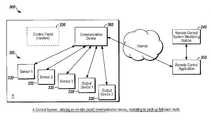
- FIG. 1is block diagram of a system 100 in accordance with disclosed embodiments operating normally.
- the system 100can include a local control system 110 installed in a region R.
- the local control system 110can include a plurality of sensors and/or output devices 120 and a control panel 130 .
- Each of the plurality of sensors and/or output devices 120can be in wired or wireless bidirectional communication with the control panel 130
- the control panel 130can be in wireless bidirectional communication with a remote control system monitoring station 140 .
- the control panel 130can communicate with the remote monitoring station 140 via the Internet.
- Monitoring communication messagescan be transmitted between the control panel 130 and the remote monitoring station 130 at predetermined intervals to demonstrate a valid connection.
- the monitoring communication messages between the control panel 130 and the remote monitoring station 140can be periodic and/or include information related to the health of the control system 110 .
- the rate at which the monitoring communication messages between the control panel 130 and the remote monitoring station 140 are transmittedcan depend on communication architecture and national and international standard requirements for the control panel 130 .
- the system 100can also include a remote control panel device 150 .
- the remote control panel device 150can be inactive.
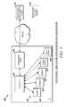
- the system 100can operate in a back-up mode, as seen in FIG. 2 .
- the control panel 130can be inactive, and the remote control panel device 150 can be activated.
- the plurality of sensors and/or output devices 120can then communicate directly with the remote control panel device 150 , which can communicate with the remote monitoring station 140 .
- the plurality of sensors and/or output devices 120can communicate with the remote control panel device 150 via the Internet.
- each of the plurality of sensors and/or output devices 120can initiate communication with the remote control panel device 150 . These embodiments may occur when the plurality of sensors and/or output devices 120 is behind a firewall and thus, cannot be contacted from outside of the local control system 110 or when the plurality of sensors and/or output devices 120 is programmed, for security reasons, not to accept incoming connections.
- the remote control panel device 150can initiate communication with each of the plurality of sensors and/or output devices 120 .
- the remote control panel device 150can initiate communication with each of the plurality of sensors and/or output devices 120 when the remote control panel device 150 is notified of a system failure, that is, that the hardware and/or software of the control panel 130 has failed.
- the remote monitoring station 140can notify the remote control panel device 150 about a system failure, and, upon being notified, the remote control panel device 150 can activate and initiate contact with each of the plurality of sensors and/or output devices 120 .
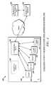
- FIG. 3is a block diagram of another system 300 in accordance with disclosed embodiments. As seen in FIG. 3 , the system 300 is operating normally.
- the system 300can include a local control system 310 installed in a region R, and the local control system 310 can include a plurality of sensors and/or output devices 320 , a control panel 330 , and a communication device 360 .
- Each of the plurality of sensors and/or output devices 320can be in wired or wireless bidirectional communication with the control panel 330 .
- the control panel 330can be in wired or wireless bidirectional communication with the communication device 360 , and the communication device 360 can be in wireless bidirectional communication with a remote control system monitoring station 340 .
- the communication device 360can communicate with the remote monitoring station 340 via the Internet.
- Monitoring communication messagescan be transmitted between the communication device 360 and the remote monitoring station 330 at predetermined intervals to demonstrate a valid connection.
- the monitoring communication messages between the communication device 360 and the remote monitoring station 340can be periodic and/or include information related to the health of the control system 310 .
- the rate at which the monitoring communication messages between the communication device 360 and the remote monitoring station 340 are transmittedcan depend on communication architecture and national and international standard requirements for the control panel 330 .
- the system 300can also include a remote control panel device 350 .
- the remote control panel device 350can be inactive.
- the system 300can operate in a back-up mode, as seen in FIG. 4 .
- the control panel 330can be inactive, and the remote control panel device 350 can be activated.
- the plurality of sensors and/or output devices 320can then communicate directly with the communication device 360 , which can communicate with the remote control panel device 350 rather than the remote monitoring station 340 .
- the remote control panel device 350can communicate with the remote monitoring station 140 .
- each of the plurality of sensors and/or output devices 320can initiate communication with the communication device 360 .
- the communication device 360can initiate communication with each of the plurality of sensors and/or output devices 320 .
- the communication device 360can initiate communication with the remote control panel device 350 . These embodiments may occur when the communication device 360 is behind a firewall and thus, cannot be contacted from outside of the local control system 310 or when the communication device 360 is programmed, for security reasons, not to accept incoming connections.
- the remote control panel device 350can initiate communication with the communication device 360 and/or any other communication devices in the control system 310 .
- the remote control panel device 350can initiate communication with the communication device 360 when the remote control panel device 350 is notified of a system failure, that is, that the hardware and/or software of the control panel 330 has failed.
- the remote monitoring station 340can notify the remote control panel device 350 about a system failure, and, upon being notified, the remote control panel device 350 can activate and initiate contact with the communication device 360 .
- the system 300can include more than one communication device 360 , for example, a plurality of communication devices 360 .
- the plurality of sensors and/or output devices 320can initiate communication with each of the plurality of communication devices 360 .
- each of the plurality of communication devices 360can initiate communication with each of the plurality of sensors and/or output devices 320 .
- systems and methods disclosed hereincan ensure that at least one communication device 360 is communicating with each of the plurality of sensors and/or output devices 320 .
- each of the plurality of communication devices 360can communicate with one another to determine one of the communication devices 360 to be the primary communication device 360 for the control system 310 .
- the remote control panel device 350can communicate with each of the plurality of communication devices 360 to determine one of the communication devices 360 to be the primary communication device 360 for the control system 310 .
- the remote control panel device 350can designate a first communication device 360 as the primary communication device 360 for the control system 310 and designate a second communication device 360 as the secondary communication device 360 for the control system 310 .
- the secondary communication device 360can be placed in stand-by mode and become active if the primary communication device 360 fails.
- the secondary communication device 360can exit the stand-by mode responsive to a message from the remote control panel device 350 or after sending a message to the remote control panel device 350 .
- each communication device 360can send periodic messages to the remote control panel device 350 . Accordingly, the remote control panel device 350 can ensure that all communication devices 360 are operating normally and transmit an alarm if there is a communication failure with any of the communication devices 360 .
- the remote control panel device 350can send periodic messages to each of the communication devices 360 .
- the communication devices 360can receive communication from the remote control panel device 350 even if the communication devices 360 are located behind a firewall.
- the rate at which monitoring communication messages are transmitted between a communication device 360 and the remote monitoring station 340can depend on communication architecture and national and international standard requirements for the control panel 330 . For example, when a communication device 360 relies on a message from the remote control panel device 350 to become active and/or to exit a stand-by mode, communication between the communication device 360 and the remote monitoring station 340 can be more frequent, thus accounting for the latency due to the periodic communication interval.
- the transmission rate of monitoring communication messagescan be maximized to minimize the cost for bandwidth use. In other embodiments, such as when bandwidth is unlimited or is very high, the transmission rate may be more frequent. It is to be understood that the transmission rate of monitoring communication messages can be more frequent when the system 100 or 300 is operating in the back-up mode.
- communication between the various components of the system 100 or 300may or may not be encrypted. Furthermore, this communication may or may not be protected from substitution, depending on an evaluated risk and the need to comply with various national and international standard requirements for control panels. For example, communication between the control system 110 , 310 and the remote control panel device 150 , 350 may be subject to the requirements listed in EN 50131-3:2009 Annex C.
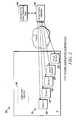
- FIG. 5is a block diagram of a remote control panel device 500 in accordance with disclosed embodiments.
- the remote control panel device 500can include a wireless transceiver 510 , a memory device 520 , control circuitry 530 , one or more programmable processors 540 , and executable control software 550 .
- the executable control software 550can be stored on a transitory or non-transitory computer readable medium, including, but not limited to, computer memory, RAM, optical storage media, magnetic storage media, flash memory, and the like.
- the executable control software 550can implement the method 600 shown in FIG. 6 as well as others described herein.
- the method 600can include remaining in an inactive mode until receiving notification of control panel failure in a remote control system as in 610 .
- the method 600can include receiving a message indicating control panel failure in the remote control system as in 620 and entering an active mode as in 630 .
- the method 600can include receiving the message indicating control panel failure from a remote monitoring station or from the control system itself, for example, a sensor, output device, or communication device in the control system.
- the method 600can include determining one communication device to be the primary communication device as in 640 .
- the method 600can include receiving a communication message from the remote control system indicating the primary communication device, or the method 600 can include transmitting a communication message to the remote control system indicating the primary communication device.
- the method 600can also include receiving initiating communication messages from sensors, output devices, and/or communication devices in the control system as in 650 or transmitting initiating communication messages to sensors, output devices, and/or communication devices in the control system as in 655 . Either way, after transmission and receipt of the initiating communication messages, the method 600 can include receiving and/or transmitting monitoring communication messages to or from the sensors, output devices, and/or communication devices in the control system at a predetermined rate as in 660 .
- the method 600can continue receiving and/or transmitting the monitoring communication messages as in 660 until receipt of a notification of control panel restoration in the remote control system as in 670 .
- the method 600can include receiving a message indicating control panel restoral from a remote monitoring station or from the control system itself, for example, a sensor, output device, or communication device in the control system.
- the methodcan again return to an inactive mode as in 610 .
Landscapes
- Engineering & Computer Science (AREA)
- Automation & Control Theory (AREA)
- Physics & Mathematics (AREA)
- General Physics & Mathematics (AREA)
- General Engineering & Computer Science (AREA)
- Signal Processing (AREA)
- Telephonic Communication Services (AREA)
- Selective Calling Equipment (AREA)
Abstract
Description
Claims (16)
Priority Applications (3)
| Application Number | Priority Date | Filing Date | Title |
|---|---|---|---|
| US13/456,788US9575476B2 (en) | 2012-04-26 | 2012-04-26 | System and method to protect against local control failure using cloud-hosted control system back-up processing |
| GB1307374.7AGB2503543B (en) | 2012-04-26 | 2013-04-24 | System and method to protect against local control failure using cloud-hosted control system back-up processing |
| CA2813983ACA2813983C (en) | 2012-04-26 | 2013-04-24 | System and method to protect against local control failure using cloud-hosted control system back-up processing |
Applications Claiming Priority (1)
| Application Number | Priority Date | Filing Date | Title |
|---|---|---|---|
| US13/456,788US9575476B2 (en) | 2012-04-26 | 2012-04-26 | System and method to protect against local control failure using cloud-hosted control system back-up processing |
Publications (2)
| Publication Number | Publication Date |
|---|---|
| US20130285799A1 US20130285799A1 (en) | 2013-10-31 |
| US9575476B2true US9575476B2 (en) | 2017-02-21 |
Family
ID=48579556
Family Applications (1)
| Application Number | Title | Priority Date | Filing Date |
|---|---|---|---|
| US13/456,788Active2034-03-29US9575476B2 (en) | 2012-04-26 | 2012-04-26 | System and method to protect against local control failure using cloud-hosted control system back-up processing |
Country Status (3)
| Country | Link |
|---|---|
| US (1) | US9575476B2 (en) |
| CA (1) | CA2813983C (en) |
| GB (1) | GB2503543B (en) |
Families Citing this family (12)
| Publication number | Priority date | Publication date | Assignee | Title |
|---|---|---|---|---|
| US9311173B2 (en)* | 2013-03-12 | 2016-04-12 | Honeywell International Inc. | Systems and methods for increasing robustness of a system with a remote server |
| WO2014165077A2 (en)* | 2013-03-12 | 2014-10-09 | Saudi Arabian Oil Company | Oil field process control system |
| WO2015198256A2 (en)* | 2014-06-26 | 2015-12-30 | Abb Technology Ltd. | A method for controlling a process plant using a redundant local supervisory controller |
| US10127797B2 (en) | 2015-02-17 | 2018-11-13 | Honeywell International Inc. | Alternative inexpensive cloud-based mass market alarm system with alarm monitoring and reporting |
| CN104714453B (en)* | 2015-03-12 | 2018-05-25 | 北京恒泰声科科技有限公司 | Acoustic wave ash ejector remote real time monitoring control system and method |
| EP3203420B1 (en) | 2016-02-08 | 2020-08-19 | Honeywell International Inc. | Removable memory card with security system support |
| US10140844B2 (en) | 2016-08-10 | 2018-11-27 | Honeywell International Inc. | Smart device distributed security system |
| US10679491B1 (en) | 2019-03-20 | 2020-06-09 | Honeywell International Inc. | Fire control panel configuration |
| US10972314B2 (en)* | 2019-06-25 | 2021-04-06 | Honeywell International Inc. | Gateway device for a fire control system |
| US10762773B1 (en) | 2019-08-19 | 2020-09-01 | Ademco Inc. | Systems and methods for building and using a false alarm predicting model to determine whether to alert a user and/or relevant authorities about an alarm signal from a security system |
| CN112083670A (en)* | 2020-08-12 | 2020-12-15 | 苏州微之备通信科技有限公司 | Communication base station centralized control system |
| US12166572B2 (en)* | 2021-06-08 | 2024-12-10 | Arlo Technologies, Inc. | Radio frequency jamming or interference detection and mitigation in an electronic monitoring system |
Citations (15)
| Publication number | Priority date | Publication date | Assignee | Title |
|---|---|---|---|---|
| WO1995016980A1 (en) | 1993-12-16 | 1995-06-22 | Digital Security Controls Ltd. | Wireless alarm system |
| US5909183A (en)* | 1996-12-26 | 1999-06-01 | Motorola, Inc. | Interactive appliance remote controller, system and method |
| US20030100962A1 (en)* | 2001-11-29 | 2003-05-29 | Tetsuji Sumita | Appliance control system and method using mobile communications terminal, and home gateway |
| US20030140270A1 (en)* | 2000-06-27 | 2003-07-24 | Siemens Ag | Redundant control system and control computer and peripheral unit for a control system of this type |
| US6725106B1 (en)* | 2000-02-28 | 2004-04-20 | Autogas Systems, Inc. | System and method for backing up distributed controllers in a data network |
| US20040102683A1 (en)* | 2002-04-16 | 2004-05-27 | Khanuja Sukhwant Singh | Method and apparatus for remotely monitoring the condition of a patient |
| US20070168058A1 (en)* | 2006-01-13 | 2007-07-19 | Emerson Process Management Power & Water Solutions , Inc. | Method for redundant controller synchronization for bump-less failover during normal and program mismatch conditions |
| US20070290830A1 (en) | 2006-06-15 | 2007-12-20 | Phase Iv Partners, Inc. | Remotely monitored security system |
| WO2008042215A1 (en) | 2006-10-02 | 2008-04-10 | Alarm.Com, Inc. | System and method for alarm signaling during alarm system destruction |
| EP1959409A2 (en) | 2007-02-13 | 2008-08-20 | Honeywell International Inc. | Auto connect virtual keypad |
| EP1970871A2 (en) | 2007-03-14 | 2008-09-17 | Honeywell Inc. | Remote service audible arming state annunciation |
| EP2114055A1 (en) | 2008-03-11 | 2009-11-04 | Honeywell International Inc. | Method of establishing virtual security keypad session from a mobile device using Java virtual machine |
| EP2124206A1 (en) | 2008-05-22 | 2009-11-25 | Honeywell International Inc. | Server based distributed security system |
| US20100083356A1 (en)* | 2008-09-29 | 2010-04-01 | Andrew Steckley | System and method for intelligent automated remote management of electromechanical devices |
| US20100312881A1 (en)* | 1999-03-18 | 2010-12-09 | James Davis | Systems and methods for controlling communication between a host computer and communication devices |
- 2012
- 2012-04-26USUS13/456,788patent/US9575476B2/enactiveActive
- 2013
- 2013-04-24GBGB1307374.7Apatent/GB2503543B/enactiveActive
- 2013-04-24CACA2813983Apatent/CA2813983C/ennot_activeExpired - Fee Related
Patent Citations (16)
| Publication number | Priority date | Publication date | Assignee | Title |
|---|---|---|---|---|
| WO1995016980A1 (en) | 1993-12-16 | 1995-06-22 | Digital Security Controls Ltd. | Wireless alarm system |
| US5909183A (en)* | 1996-12-26 | 1999-06-01 | Motorola, Inc. | Interactive appliance remote controller, system and method |
| US20100312881A1 (en)* | 1999-03-18 | 2010-12-09 | James Davis | Systems and methods for controlling communication between a host computer and communication devices |
| US6725106B1 (en)* | 2000-02-28 | 2004-04-20 | Autogas Systems, Inc. | System and method for backing up distributed controllers in a data network |
| US20030140270A1 (en)* | 2000-06-27 | 2003-07-24 | Siemens Ag | Redundant control system and control computer and peripheral unit for a control system of this type |
| US20030100962A1 (en)* | 2001-11-29 | 2003-05-29 | Tetsuji Sumita | Appliance control system and method using mobile communications terminal, and home gateway |
| US20040102683A1 (en)* | 2002-04-16 | 2004-05-27 | Khanuja Sukhwant Singh | Method and apparatus for remotely monitoring the condition of a patient |
| US20070168058A1 (en)* | 2006-01-13 | 2007-07-19 | Emerson Process Management Power & Water Solutions , Inc. | Method for redundant controller synchronization for bump-less failover during normal and program mismatch conditions |
| US20070290830A1 (en) | 2006-06-15 | 2007-12-20 | Phase Iv Partners, Inc. | Remotely monitored security system |
| WO2008042215A1 (en) | 2006-10-02 | 2008-04-10 | Alarm.Com, Inc. | System and method for alarm signaling during alarm system destruction |
| EP1959409A2 (en) | 2007-02-13 | 2008-08-20 | Honeywell International Inc. | Auto connect virtual keypad |
| EP1970871A2 (en) | 2007-03-14 | 2008-09-17 | Honeywell Inc. | Remote service audible arming state annunciation |
| EP2114055A1 (en) | 2008-03-11 | 2009-11-04 | Honeywell International Inc. | Method of establishing virtual security keypad session from a mobile device using Java virtual machine |
| EP2124206A1 (en) | 2008-05-22 | 2009-11-25 | Honeywell International Inc. | Server based distributed security system |
| US20090322527A1 (en) | 2008-05-22 | 2009-12-31 | Honeywell International Inc. | Server based distributed security system |
| US20100083356A1 (en)* | 2008-09-29 | 2010-04-01 | Andrew Steckley | System and method for intelligent automated remote management of electromechanical devices |
Non-Patent Citations (1)
| Title |
|---|
| Combined Search and Examination Report for corresponding GB application GB1307374.7 dated Oct. 24, 2013. |
Also Published As
| Publication number | Publication date |
|---|---|
| CA2813983A1 (en) | 2013-10-26 |
| CA2813983C (en) | 2021-01-26 |
| GB201307374D0 (en) | 2013-06-05 |
| GB2503543B (en) | 2014-09-17 |
| GB2503543A (en) | 2014-01-01 |
| US20130285799A1 (en) | 2013-10-31 |
Similar Documents
| Publication | Publication Date | Title |
|---|---|---|
| US9575476B2 (en) | System and method to protect against local control failure using cloud-hosted control system back-up processing | |
| US9710251B2 (en) | Software updates from a security control unit | |
| CN109102686B (en) | System and method for preventing false alarms during alarm sensitivity threshold changes in fire alarm systems | |
| ES2751098T3 (en) | Network coupling equipment and transmission procedure for packet-based data networks in process control systems or operation control systems | |
| EP2466564B1 (en) | System and method of emergency operation of an alarm system | |
| US10063416B2 (en) | Bidirectional redundant mesh networks | |
| US20170272451A1 (en) | Monitoring apparatus and communication system | |
| KR20160107094A (en) | Ship gateway apparatus and status information displaying method in ship gateway apparatus | |
| US12094322B2 (en) | On-premises communication bridges for premises security systems | |
| US10523497B2 (en) | Systems and methods for dynamic output control hierarchy for wireless fire systems and for fire protection before and during the installation thereof | |
| US20200264685A1 (en) | Systems and methods for automatically activating self-test devices of sensors of a security system | |
| CN107204857B (en) | Communication bus line isolator | |
| JP6474480B1 (en) | Monitoring system | |
| JP7303083B2 (en) | Behavior monitoring device, behavior monitoring method, behavior monitoring program, and behavior monitoring system | |
| KR101852052B1 (en) | Warning device, gateway capable of wireless communicating with the warning device, and method for providing warning service using the same | |
| US20200288415A1 (en) | Systems and methods for reconnecting a dropped wireless network node | |
| JP2009232099A (en) | Equipment management system | |
| JP2017120959A (en) | One-way communication device and plant monitoring control system | |
| US20090231118A1 (en) | Forwarding and fall back monitoring in an alarm system | |
| JP2017098856A (en) | Public line communication device and control monitoring system | |
| KR100788433B1 (en) | Unmanned security system and device using both telephone line and internet network | |
| JP2010278610A (en) | Data communication system | |
| JP2010223856A (en) | Gas meter system | |
| KR20150122002A (en) | Video Security System | |
| TWM499014U (en) | Wireless security equipment |
Legal Events
| Date | Code | Title | Description |
|---|---|---|---|
| AS | Assignment | Owner name:HONEYWELL INTERNATIONAL INC., NEW JERSEY Free format text:ASSIGNMENT OF ASSIGNORS INTEREST;ASSIGNORS:PROBIN, ROBERT JOHN;ZAKREWSKI, DAVID S.;SIGNING DATES FROM 20120425 TO 20120426;REEL/FRAME:028112/0907 | |
| STCF | Information on status: patent grant | Free format text:PATENTED CASE | |
| AS | Assignment | Owner name:JPMORGAN CHASE BANK, N.A., AS ADMINISTRATIVE AGENT, NEW YORK Free format text:SECURITY INTEREST;ASSIGNOR:ADEMCO INC.;REEL/FRAME:047337/0577 Effective date:20181025 Owner name:JPMORGAN CHASE BANK, N.A., AS ADMINISTRATIVE AGENT Free format text:SECURITY INTEREST;ASSIGNOR:ADEMCO INC.;REEL/FRAME:047337/0577 Effective date:20181025 | |
| AS | Assignment | Owner name:ADEMCO INC., MINNESOTA Free format text:ASSIGNMENT OF ASSIGNORS INTEREST;ASSIGNOR:HONEYWELL INTERNATIONAL INC.;REEL/FRAME:047909/0425 Effective date:20181029 | |
| AS | Assignment | Owner name:ADEMCO INC., MINNESOTA Free format text:CORRECTIVE ASSIGNMENT TO CORRECT THE PREVIOUS RECORDING BY NULLIFICATION. THE INCORRECTLY RECORDED PATENT NUMBERS 8545483, 8612538 AND 6402691 PREVIOUSLY RECORDED AT REEL: 047909 FRAME: 0425. ASSIGNOR(S) HEREBY CONFIRMS THE ASSIGNMENT;ASSIGNOR:HONEYWELL INTERNATIONAL INC.;REEL/FRAME:050431/0053 Effective date:20190215 | |
| MAFP | Maintenance fee payment | Free format text:PAYMENT OF MAINTENANCE FEE, 4TH YEAR, LARGE ENTITY (ORIGINAL EVENT CODE: M1551); ENTITY STATUS OF PATENT OWNER: LARGE ENTITY Year of fee payment:4 | |
| MAFP | Maintenance fee payment | Free format text:PAYMENT OF MAINTENANCE FEE, 8TH YEAR, LARGE ENTITY (ORIGINAL EVENT CODE: M1552); ENTITY STATUS OF PATENT OWNER: LARGE ENTITY Year of fee payment:8 | |
| AS | Assignment | Owner name:RESIDEO LLC, DELAWARE Free format text:CHANGE OF NAME;ASSIGNOR:ADEMCO INC.;REEL/FRAME:071546/0001 Effective date:20241227 |