US9574574B2 - Gas turbine engine airfoil - Google Patents
Gas turbine engine airfoilDownload PDFInfo
- Publication number
- US9574574B2 US9574574B2US15/191,860US201615191860AUS9574574B2US 9574574 B2US9574574 B2US 9574574B2US 201615191860 AUS201615191860 AUS 201615191860AUS 9574574 B2US9574574 B2US 9574574B2
- Authority
- US
- United States
- Prior art keywords
- span position
- dihedral
- airfoil
- range
- airfoil according
- Prior art date
- Legal status (The legal status is an assumption and is not a legal conclusion. Google has not performed a legal analysis and makes no representation as to the accuracy of the status listed.)
- Active
Links
Images


Classifications
- F—MECHANICAL ENGINEERING; LIGHTING; HEATING; WEAPONS; BLASTING
- F01—MACHINES OR ENGINES IN GENERAL; ENGINE PLANTS IN GENERAL; STEAM ENGINES
- F01D—NON-POSITIVE DISPLACEMENT MACHINES OR ENGINES, e.g. STEAM TURBINES
- F01D5/00—Blades; Blade-carrying members; Heating, heat-insulating, cooling or antivibration means on the blades or the members
- F01D5/12—Blades
- F01D5/14—Form or construction
- F01D5/141—Shape, i.e. outer, aerodynamic form
- F—MECHANICAL ENGINEERING; LIGHTING; HEATING; WEAPONS; BLASTING
- F04—POSITIVE - DISPLACEMENT MACHINES FOR LIQUIDS; PUMPS FOR LIQUIDS OR ELASTIC FLUIDS
- F04D—NON-POSITIVE-DISPLACEMENT PUMPS
- F04D29/00—Details, component parts, or accessories
- F04D29/26—Rotors specially for elastic fluids
- F04D29/32—Rotors specially for elastic fluids for axial flow pumps
- F04D29/38—Blades
- F04D29/384—Blades characterised by form
- F—MECHANICAL ENGINEERING; LIGHTING; HEATING; WEAPONS; BLASTING
- F01—MACHINES OR ENGINES IN GENERAL; ENGINE PLANTS IN GENERAL; STEAM ENGINES
- F01D—NON-POSITIVE DISPLACEMENT MACHINES OR ENGINES, e.g. STEAM TURBINES
- F01D5/00—Blades; Blade-carrying members; Heating, heat-insulating, cooling or antivibration means on the blades or the members
- F01D5/12—Blades
- F01D5/14—Form or construction
- F01D5/141—Shape, i.e. outer, aerodynamic form
- F01D5/145—Means for influencing boundary layers or secondary circulations
- F—MECHANICAL ENGINEERING; LIGHTING; HEATING; WEAPONS; BLASTING
- F04—POSITIVE - DISPLACEMENT MACHINES FOR LIQUIDS; PUMPS FOR LIQUIDS OR ELASTIC FLUIDS
- F04D—NON-POSITIVE-DISPLACEMENT PUMPS
- F04D29/00—Details, component parts, or accessories
- F04D29/26—Rotors specially for elastic fluids
- F04D29/32—Rotors specially for elastic fluids for axial flow pumps
- F04D29/321—Rotors specially for elastic fluids for axial flow pumps for axial flow compressors
- F04D29/324—Blades
- F—MECHANICAL ENGINEERING; LIGHTING; HEATING; WEAPONS; BLASTING
- F04—POSITIVE - DISPLACEMENT MACHINES FOR LIQUIDS; PUMPS FOR LIQUIDS OR ELASTIC FLUIDS
- F04D—NON-POSITIVE-DISPLACEMENT PUMPS
- F04D29/00—Details, component parts, or accessories
- F04D29/26—Rotors specially for elastic fluids
- F04D29/32—Rotors specially for elastic fluids for axial flow pumps
- F04D29/325—Rotors specially for elastic fluids for axial flow pumps for axial flow fans
- F—MECHANICAL ENGINEERING; LIGHTING; HEATING; WEAPONS; BLASTING
- F05—INDEXING SCHEMES RELATING TO ENGINES OR PUMPS IN VARIOUS SUBCLASSES OF CLASSES F01-F04
- F05D—INDEXING SCHEME FOR ASPECTS RELATING TO NON-POSITIVE-DISPLACEMENT MACHINES OR ENGINES, GAS-TURBINES OR JET-PROPULSION PLANTS
- F05D2220/00—Application
- F05D2220/30—Application in turbines
- F05D2220/32—Application in turbines in gas turbines
- F—MECHANICAL ENGINEERING; LIGHTING; HEATING; WEAPONS; BLASTING
- F05—INDEXING SCHEMES RELATING TO ENGINES OR PUMPS IN VARIOUS SUBCLASSES OF CLASSES F01-F04
- F05D—INDEXING SCHEME FOR ASPECTS RELATING TO NON-POSITIVE-DISPLACEMENT MACHINES OR ENGINES, GAS-TURBINES OR JET-PROPULSION PLANTS
- F05D2220/00—Application
- F05D2220/30—Application in turbines
- F05D2220/36—Application in turbines specially adapted for the fan of turbofan engines
- F—MECHANICAL ENGINEERING; LIGHTING; HEATING; WEAPONS; BLASTING
- F05—INDEXING SCHEMES RELATING TO ENGINES OR PUMPS IN VARIOUS SUBCLASSES OF CLASSES F01-F04
- F05D—INDEXING SCHEME FOR ASPECTS RELATING TO NON-POSITIVE-DISPLACEMENT MACHINES OR ENGINES, GAS-TURBINES OR JET-PROPULSION PLANTS
- F05D2240/00—Components
- F05D2240/20—Rotors
- F05D2240/30—Characteristics of rotor blades, i.e. of any element transforming dynamic fluid energy to or from rotational energy and being attached to a rotor
- F05D2240/303—Characteristics of rotor blades, i.e. of any element transforming dynamic fluid energy to or from rotational energy and being attached to a rotor related to the leading edge of a rotor blade
- F—MECHANICAL ENGINEERING; LIGHTING; HEATING; WEAPONS; BLASTING
- F05—INDEXING SCHEMES RELATING TO ENGINES OR PUMPS IN VARIOUS SUBCLASSES OF CLASSES F01-F04
- F05D—INDEXING SCHEME FOR ASPECTS RELATING TO NON-POSITIVE-DISPLACEMENT MACHINES OR ENGINES, GAS-TURBINES OR JET-PROPULSION PLANTS
- F05D2240/00—Components
- F05D2240/20—Rotors
- F05D2240/30—Characteristics of rotor blades, i.e. of any element transforming dynamic fluid energy to or from rotational energy and being attached to a rotor
- F05D2240/304—Characteristics of rotor blades, i.e. of any element transforming dynamic fluid energy to or from rotational energy and being attached to a rotor related to the trailing edge of a rotor blade
- F—MECHANICAL ENGINEERING; LIGHTING; HEATING; WEAPONS; BLASTING
- F05—INDEXING SCHEMES RELATING TO ENGINES OR PUMPS IN VARIOUS SUBCLASSES OF CLASSES F01-F04
- F05D—INDEXING SCHEME FOR ASPECTS RELATING TO NON-POSITIVE-DISPLACEMENT MACHINES OR ENGINES, GAS-TURBINES OR JET-PROPULSION PLANTS
- F05D2250/00—Geometry
- F05D2250/30—Arrangement of components
- F05D2250/38—Arrangement of components angled, e.g. sweep angle
- F—MECHANICAL ENGINEERING; LIGHTING; HEATING; WEAPONS; BLASTING
- F05—INDEXING SCHEMES RELATING TO ENGINES OR PUMPS IN VARIOUS SUBCLASSES OF CLASSES F01-F04
- F05D—INDEXING SCHEME FOR ASPECTS RELATING TO NON-POSITIVE-DISPLACEMENT MACHINES OR ENGINES, GAS-TURBINES OR JET-PROPULSION PLANTS
- F05D2250/00—Geometry
- F05D2250/70—Shape
- Y—GENERAL TAGGING OF NEW TECHNOLOGICAL DEVELOPMENTS; GENERAL TAGGING OF CROSS-SECTIONAL TECHNOLOGIES SPANNING OVER SEVERAL SECTIONS OF THE IPC; TECHNICAL SUBJECTS COVERED BY FORMER USPC CROSS-REFERENCE ART COLLECTIONS [XRACs] AND DIGESTS
- Y02—TECHNOLOGIES OR APPLICATIONS FOR MITIGATION OR ADAPTATION AGAINST CLIMATE CHANGE
- Y02T—CLIMATE CHANGE MITIGATION TECHNOLOGIES RELATED TO TRANSPORTATION
- Y02T50/00—Aeronautics or air transport
- Y02T50/60—Efficient propulsion technologies, e.g. for aircraft
Definitions
- This disclosurerelates generally to an airfoil for gas turbine engines, and more particularly to leading and trailing edge aerodynamic dihedral relative to span for gas turbine engine blades.
- a turbine enginesuch as a gas turbine engine typically includes a fan section, a compressor section, a combustor section and a turbine section. Air entering the compressor section is compressed and delivered into the combustor section where it is mixed with fuel and ignited to generate a high-speed exhaust gas flow. The high-speed exhaust gas flow expands through the turbine section to drive the compressor and the fan section.
- the compressor sectiontypically includes low and high pressure compressors, and the turbine section includes low and high pressure turbines.
- the propulsive efficiency of a gas turbine enginedepends on many different factors, such as the design of the engine and the resulting performance debits on the fan that propels the engine.
- the fanmay rotate at a high rate of speed such that air passes over the fan airfoils at transonic or supersonic speeds.
- the fast-moving aircreates flow discontinuities or shocks that result in irreversible propulsive losses.
- physical interaction between the fan and the aircauses downstream turbulence and further losses.
- an airfoil for a turbine engineincludes an airfoil that has pressure and suction sides that extend in a radial direction from a 0% span position at an inner flow path location to a 100% span position at an airfoil tip.
- the airfoilhas a relationship between a leading edge dihedral and a span position. The leading edge dihedral is negative from the 0% span position to the 100% span position.
- a positive dihedralcorresponds to suction side-leaning, and a negative dihedral corresponds to pressure side-leaning.
- the airfoilhas a relationship between a trailing edge dihedral and a span position. The trailing edge dihedral is positive from the 0% span position to the 100% span position.
- a positive dihedralcorresponds to suction side-leaning and a negative dihedral corresponds to pressure side-leaning.
- the leading edge dihedral at the 0% span positionis in the range of ⁇ 3° to ⁇ 12°.
- the leading edge dihedral at the 0% span positionis about ⁇ 4°.
- the leading edge dihedral at the 0% span positionis about ⁇ 10°.
- the leading edge dihedralextends from the 0% span position to a 20% span position and has a leading edge dihedral in a range of ⁇ 2° to ⁇ 6°.
- the leading edge dihedralincludes a first point at a 75% span position and extends generally linearly from the first point to a second point at the 85% span position.
- the first pointis in a range of ⁇ 8° to ⁇ 10° dihedral.
- the second pointis in a range of ⁇ 3° to ⁇ 6° dihedral.
- a maximum negative dihedralis in a range of 95-100% span position.
- a least negative dihedralis in a range of 5-15% span position.
- a maximum negative dihedralis in a range of 65-75% span position.
- a least negative dihedralis in a range of 0-10% span position.
- a maximum negative dihedralis in a range of 50-60% span position.
- the relationshipprovides a generally C-shaped curve from the 0% span position to a 50% span position and then a 90% span position.
- a trailing edge dihedral at the 0% span positionis in a range of 20° to 25°.
- a trailing edge dihedral at about the 50% span positionis in a range of 2° to 6°.
- a trailing edge dihedral at the 90% span positionis in a range of 16° to 22°.
- a positive-most trailing edge dihedral in a 80%-100% span positionis within 5° of the trailing edge dihedral in the 0% span position.
- a least positive trailing edge dihedralis in a 40%-55% span position.
- the airfoilis a fan blade for a gas turbine engine.
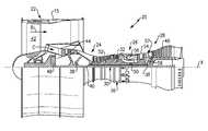
- FIG. 1schematically illustrates a gas turbine engine embodiment.
- FIG. 2Ais a perspective view of a portion of a fan section.
- FIG. 2Bis a schematic cross-sectional view of the fan section.
- FIG. 2Cis a cross-sectional view a fan blade taken along line 2 C- 2 C in FIG. 2B .
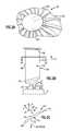
- FIG. 3Ais a schematic view of fan blade span positions.
- FIG. 3Bis a schematic representation of a dihedral angle for an airfoil.
- FIG. 4Aillustrates a relationship between a leading edge aerodynamic dihedral angle and a span position for a set of first example airfoils and a prior art curve.
- FIG. 4Billustrates a relationship between a trailing edge aerodynamic dihedral angle and a span position for a set of first example airfoils and a prior art curve.
- FIG. 5Aillustrates a relationship between a leading edge aerodynamic dihedral angle and a span position for a set of second example airfoils and a prior art curve.
- FIG. 5Billustrates a relationship between a trailing edge aerodynamic dihedral angle and a span position for set of second example airfoils and a prior art curve.
- FIG. 1schematically illustrates a gas turbine engine 20 .
- the gas turbine engine 20is disclosed herein as a two-spool turbofan that generally incorporates a fan section 22 , a compressor section 24 , a combustor section 26 and a turbine section 28 .
- Alternative enginesmight include an augmenter section (not shown) among other systems or features.
- the fan section 22drives air along a bypass flow path B in a bypass duct defined within a nacelle 15
- the compressor section 24drives air along a core flow path C for compression and communication into the combustor section 26 then expansion through the turbine section 28 .
- the exemplary engine 20generally includes a low speed spool 30 and a high speed spool 32 mounted for rotation about an engine central longitudinal axis X relative to an engine static structure 36 via several bearing systems 38 . It should be understood that various bearing systems 38 at various locations may alternatively or additionally be provided, and the location of bearing systems 38 may be varied as appropriate to the application.
- the low speed spool 30generally includes an inner shaft 40 that interconnects a fan 42 , a first (or low) pressure compressor 44 and a first (or low) pressure turbine 46 .
- the inner shaft 40is connected to the fan 42 through a speed change mechanism, which in exemplary gas turbine engine 20 is illustrated as a geared architecture 48 to drive the fan 42 at a lower speed than the low speed spool 30 .
- the high speed spool 32includes an outer shaft 50 that interconnects a second (or high) pressure compressor 52 and a second (or high) pressure turbine 54 .
- a combustor 56is arranged in exemplary gas turbine 20 between the high pressure compressor 52 and the high pressure turbine 54 .
- a mid-turbine frame 57 of the engine static structure 36is arranged generally between the high pressure turbine 54 and the low pressure turbine 46 .
- the mid-turbine frame 57further supports bearing systems 38 in the turbine section 28 .
- the inner shaft 40 and the outer shaft 50are concentric and rotate via bearing systems 38 about the engine central longitudinal axis X which is collinear with their longitudinal axes.
- the core airflowis compressed by the low pressure compressor 44 then the high pressure compressor 52 , mixed and burned with fuel in the combustor 56 , then expanded over the high pressure turbine 54 and low pressure turbine 46 .
- the mid-turbine frame 57includes airfoils 59 which are in the core airflow path C.
- the turbines 46 , 54rotationally drive the respective low speed spool 30 and high speed spool 32 in response to the expansion.
- gear system 48may be located aft of combustor section 26 or even aft of turbine section 28
- fan section 22may be positioned forward or aft of the location of gear system 48 .
- the engine 20 in one exampleis a high-bypass geared aircraft engine.
- the engine 20 bypass ratiois greater than about six (6), with an example embodiment being greater than about ten (10)
- the geared architecture 48is an epicyclic gear train, such as a planetary gear system or other gear system, with a gear reduction ratio of greater than about 2.3 and the low pressure turbine 46 has a pressure ratio that is greater than about five.
- the engine 20 bypass ratiois greater than about ten (10:1)
- the fan diameteris significantly larger than that of the low pressure compressor 44
- the low pressure turbine 46has a pressure ratio that is greater than about five (5:1).
- the example gas turbine engineincludes the fan 42 that comprises in one non-limiting embodiment less than about twenty-six (26) fan blades. In another non-limiting embodiment, the fan section 22 includes less than about twenty (20) fan blades. Moreover, in one disclosed embodiment the low pressure turbine 46 includes no more than about six (6) turbine rotors schematically indicated at 34 . In another non-limiting example embodiment the low pressure turbine 46 includes about three (3) turbine rotors. A ratio between the number of fan blades 42 and the number of low pressure turbine rotors is between about 3.3 and about 8.6. The example low pressure turbine 46 provides the driving power to rotate the fan section 22 and therefore the relationship between the number of turbine rotors 34 in the low pressure turbine 46 and the number of blades 42 in the fan section 22 disclose an example gas turbine engine 20 with increased power transfer efficiency.
- the fan section 22 of the engine 20is designed for a particular flight condition—typically cruise at about 0.8 Mach and about 35,000 feet.
- TSFCThrust Specific Fuel Consumption
- Low fan pressure ratiois the pressure ratio across the fan blade alone, without a Fan Exit Guide Vane (“FEGV”) system.
- the low fan pressure ratio as disclosed herein according to one non-limiting embodimentis less than about 1.55.
- the low fan pressure ratiois less than about 1.45. In another non-limiting embodiment the low fan pressure ratio is from 1.1 to 1.45.
- Low corrected fan tip speedis the actual fan tip speed in ft/sec divided by an industry standard temperature correction of [(Tram ° R)/(518.7° R)] 0.5 .
- the “low corrected fan tip speed” as disclosed herein according to another non-limiting embodimentis less than about 1200 ft/second.
- the fan blade 42is supported by a fan hub 60 that is rotatable about the axis X, which corresponds to the X direction.
- Each fan blade 42includes an airfoil 64 extending in a radial span direction R from a root 62 to a tip 66 .
- a 0% span positioncorresponds to a section of the airfoil 64 at the inner flow path (e.g., a platform), and a 100% span position corresponds to a section of the airfoil 64 at the tip 66 .
- the root 62is received in a correspondingly shaped slot in the fan hub 60 .
- the airfoil 64extends radially outward of the platform, which provides the inner flow path.
- the platformmay be integral with the fan blade or separately secured to the fan hub, for example.
- a spinner 66is supported relative to the fan hub 60 to provide an aerodynamic inner flow path into the fan section 22 .
- the airfoil 64has an exterior surface 76 providing a contour that extends from a leading edge 68 aftward in a chord-wise direction H to a trailing edge 70 , as shown in FIG. 2C .
- Pressure and suction sides 72 , 74join one another at the leading and trailing edges 68 , 70 and are spaced apart from one another in an airfoil thickness direction T.
- An array of the fan blades 42are positioned about the axis X in a circumferential or tangential direction Y. Any suitable number of fan blades may be used in a given application.
- the exterior surface 76 of the airfoil 64generates lift based upon its geometry and directs flow along the core flow path C.
- the fan blade 42may be constructed from a composite material, or an aluminum alloy or titanium alloy, or a combination of one or more of these. Abrasion-resistant coatings or other protective coatings may be applied to the fan blade 42 .
- the curves and associated valuesassume a fan in a hot, running condition (typically cruise).
- span positionsa schematically illustrated from 0% to 100% in 10% increments. Each section at a given span position is provided by a conical cut that corresponds to the shape of the core flow path, as shown by the large dashed lines.
- the 0% span positioncorresponds to the radially innermost location where the airfoil meets the fillet joining the airfoil to the platform.
- the 0% span positioncorresponds to the radially innermost location where the discrete platform meets the exterior surface of the airfoil.
- leading and trailing edge sweepvaries between a hot, running condition and a cold, static (“on the bench”) condition.
- FIG. 3BAn aerodynamic dihedral angle D (simply referred to as “dihedral”) is schematically illustrated in FIG. 3B for a simple airfoil.
- An axisymmetric stream surface Spasses through the airfoil 64 at a location that corresponds to a span location ( FIG. 3A ).
- the dihedral Drelates to the angle at which a line L along the leading or trailing edge tilts with respect to the stream surface S.
- a plane Pis normal to the line L and forms an angle with the tangential direction Y, providing the dihedral D.
- a positive dihedral Dcorresponds to the line tilting toward the suction side (suction side-leaning), and a negative dihedral D corresponds to the line tilting toward the pressure side (pressure side-leaning).
- the leading edge dihedral at the 0% span position( 92 in FIG. 4A ; 104 in FIG. 5A ) is in the range of ⁇ 3° to ⁇ 12°. In the examples shown in FIGS. 4A and 5A , the leading edge dihedral at the 0% span position is about ⁇ 4°.
- the leading edge dihedralextends from the 0% span position to a 20% span position ( 96 in FIG. 4A ; 108 in FIG. 5A ) having a leading edge dihedral in a range of ⁇ 2° to ⁇ 6°.
- the leading edge dihedralincludes a first point ( 100 in FIG. 4A ; 110 in FIG. 5A ) at a 75% span position and extends generally linearly from the first point to a second point ( 102 in FIG. 4A ; 114 in FIG. 5A ) at the 85% span position.
- the first pointis in a range of ⁇ 8° to ⁇ 10° dihedral
- the second pointis in a range of ⁇ 3° to ⁇ 6° dihedral.
- a maximum negative dihedral 98is in a range of 95-100% span position.
- a least negative dihedral 94is in a range of 5-15% span position.
- a maximum negative dihedral 110is in a range of 65-75% span position.
- a least negative dihedral 106is in a range of 0-10% span position.
- a trailing edge dihedral ( 130 in FIG. 4B ; 140 in FIG. 5B ) at the 0% span positionis in a range of 20° to 25°.
- a trailing edge dihedral ( 132 in FIG. 4B ; 142 in FIG. 5B ) at about the 50% span positionis in a range of 2° to 6°.
- a trailing edge dihedral ( 137 in FIG. 4B ; 147 in FIG. 5B ) at the 90% span positionis in a range of 16° to 22°. From a 65% span position ( 134 in FIG. 4B ; 144 in FIG. 5B ) to a 75% span position ( 136 in FIG. 4B ; 146 in FIG. 5B ) the trailing edge dihedral increases about 5°.
- a positive-most trailing edge dihedral ( 138 in FIG. 4B ; 148 in FIG. 5B ) in a 80%-100% span positionis within 5° of the trailing edge dihedral in the 0% span position ( 130 in FIG. 4B ; 140 in FIG. 5B ).
- a least positive trailing edge dihedral ( 132 in FIG. 4B ; 142 in FIG. 5B )is in a 40%-55% span position.
- the leading and trailing edge aerodynamic dihedral in a hot, running condition along the span of the airfoils 64relate to the contour of the airfoil and provide necessary fan operation in cruise at the lower, preferential speeds enabled by the geared architecture 48 in order to enhance aerodynamic functionality and thermal efficiency.
- the hot, running conditionis the condition during cruise of the gas turbine engine 20 .
- the leading and trailing edge aerodynamic dihedral in the hot, running conditioncan be determined in a known manner using numerical analysis, such as finite element analysis.
Landscapes
- Engineering & Computer Science (AREA)
- Mechanical Engineering (AREA)
- General Engineering & Computer Science (AREA)
- Physics & Mathematics (AREA)
- Fluid Mechanics (AREA)
- Structures Of Non-Positive Displacement Pumps (AREA)
- Chemical & Material Sciences (AREA)
- Combustion & Propulsion (AREA)
- Architecture (AREA)
Abstract
Description
Claims (21)
Priority Applications (3)
| Application Number | Priority Date | Filing Date | Title |
|---|---|---|---|
| US15/191,860US9574574B2 (en) | 2014-02-19 | 2016-06-24 | Gas turbine engine airfoil |
| US15/418,115US9777580B2 (en) | 2014-02-19 | 2017-01-27 | Gas turbine engine airfoil |
| US15/706,025US9988908B2 (en) | 2014-02-19 | 2017-09-15 | Gas turbine engine airfoil |
Applications Claiming Priority (4)
| Application Number | Priority Date | Filing Date | Title |
|---|---|---|---|
| US201461942025P | 2014-02-19 | 2014-02-19 | |
| US14/624,025US9353628B2 (en) | 2014-02-19 | 2015-02-17 | Gas turbine engine airfoil |
| US14/876,995US9399917B2 (en) | 2014-02-19 | 2015-10-07 | Gas turbine engine airfoil |
| US15/191,860US9574574B2 (en) | 2014-02-19 | 2016-06-24 | Gas turbine engine airfoil |
Related Parent Applications (1)
| Application Number | Title | Priority Date | Filing Date |
|---|---|---|---|
| US14/876,995ContinuationUS9399917B2 (en) | 2014-02-19 | 2015-10-07 | Gas turbine engine airfoil |
Related Child Applications (1)
| Application Number | Title | Priority Date | Filing Date |
|---|---|---|---|
| US15/418,115ContinuationUS9777580B2 (en) | 2014-02-19 | 2017-01-27 | Gas turbine engine airfoil |
Publications (2)
| Publication Number | Publication Date |
|---|---|
| US20160298643A1 US20160298643A1 (en) | 2016-10-13 |
| US9574574B2true US9574574B2 (en) | 2017-02-21 |
Family
ID=53878762
Family Applications (5)
| Application Number | Title | Priority Date | Filing Date |
|---|---|---|---|
| US14/624,025Active2035-02-23US9353628B2 (en) | 2014-02-19 | 2015-02-17 | Gas turbine engine airfoil |
| US14/876,995ActiveUS9399917B2 (en) | 2014-02-19 | 2015-10-07 | Gas turbine engine airfoil |
| US15/191,860ActiveUS9574574B2 (en) | 2014-02-19 | 2016-06-24 | Gas turbine engine airfoil |
| US15/418,115ActiveUS9777580B2 (en) | 2014-02-19 | 2017-01-27 | Gas turbine engine airfoil |
| US15/706,025ActiveUS9988908B2 (en) | 2014-02-19 | 2017-09-15 | Gas turbine engine airfoil |
Family Applications Before (2)
| Application Number | Title | Priority Date | Filing Date |
|---|---|---|---|
| US14/624,025Active2035-02-23US9353628B2 (en) | 2014-02-19 | 2015-02-17 | Gas turbine engine airfoil |
| US14/876,995ActiveUS9399917B2 (en) | 2014-02-19 | 2015-10-07 | Gas turbine engine airfoil |
Family Applications After (2)
| Application Number | Title | Priority Date | Filing Date |
|---|---|---|---|
| US15/418,115ActiveUS9777580B2 (en) | 2014-02-19 | 2017-01-27 | Gas turbine engine airfoil |
| US15/706,025ActiveUS9988908B2 (en) | 2014-02-19 | 2017-09-15 | Gas turbine engine airfoil |
Country Status (3)
| Country | Link |
|---|---|
| US (5) | US9353628B2 (en) |
| EP (1) | EP3108106B1 (en) |
| WO (1) | WO2015126449A1 (en) |
Cited By (4)
| Publication number | Priority date | Publication date | Assignee | Title |
|---|---|---|---|---|
| US20170130586A1 (en)* | 2014-02-19 | 2017-05-11 | United Technologies Corporation | Gas turbine engine airfoil |
| US20250027415A1 (en)* | 2021-11-29 | 2025-01-23 | Safran Aircraft Engines | Blade for a ducted fan of a turbomachine |
| US20250033760A1 (en)* | 2021-11-29 | 2025-01-30 | Safran Aircraft Engines | Blade for an unducted fan of a turbomachine |
| US12441460B2 (en)* | 2021-11-29 | 2025-10-14 | Safran Aircraft Engines | Blade for an unducted fan of a turbomachine |
Families Citing this family (33)
| Publication number | Priority date | Publication date | Assignee | Title |
|---|---|---|---|---|
| US9347323B2 (en) | 2014-02-19 | 2016-05-24 | United Technologies Corporation | Gas turbine engine airfoil total chord relative to span |
| WO2015175056A2 (en) | 2014-02-19 | 2015-11-19 | United Technologies Corporation | Gas turbine engine airfoil |
| WO2015126715A1 (en) | 2014-02-19 | 2015-08-27 | United Technologies Corporation | Gas turbine engine airfoil |
| US9163517B2 (en) | 2014-02-19 | 2015-10-20 | United Technologies Corporation | Gas turbine engine airfoil |
| EP3108116B1 (en) | 2014-02-19 | 2024-01-17 | RTX Corporation | Gas turbine engine |
| US20170175760A1 (en)* | 2014-02-19 | 2017-06-22 | United Technologies Corporation | Gas turbine engine airfoil |
| US10557477B2 (en) | 2014-02-19 | 2020-02-11 | United Technologies Corporation | Gas turbine engine airfoil |
| EP3114321B1 (en) | 2014-02-19 | 2019-04-17 | United Technologies Corporation | Gas turbine engine airfoil |
| US10605259B2 (en) | 2014-02-19 | 2020-03-31 | United Technologies Corporation | Gas turbine engine airfoil |
| EP3108123B1 (en) | 2014-02-19 | 2023-10-04 | Raytheon Technologies Corporation | Turbofan engine with geared architecture and lpc airfoils |
| EP3108103B1 (en) | 2014-02-19 | 2023-09-27 | Raytheon Technologies Corporation | Fan blade for a gas turbine engine |
| EP3108101B1 (en) | 2014-02-19 | 2022-04-20 | Raytheon Technologies Corporation | Gas turbine engine airfoil |
| US10393139B2 (en) | 2014-02-19 | 2019-08-27 | United Technologies Corporation | Gas turbine engine airfoil |
| WO2015126454A1 (en) | 2014-02-19 | 2015-08-27 | United Technologies Corporation | Gas turbine engine airfoil |
| EP3108113A4 (en) | 2014-02-19 | 2017-03-15 | United Technologies Corporation | Gas turbine engine airfoil |
| WO2015126450A1 (en) | 2014-02-19 | 2015-08-27 | United Technologies Corporation | Gas turbine engine airfoil |
| US9567858B2 (en) | 2014-02-19 | 2017-02-14 | United Technologies Corporation | Gas turbine engine airfoil |
| US10570916B2 (en) | 2014-02-19 | 2020-02-25 | United Technologies Corporation | Gas turbine engine airfoil |
| WO2015175043A2 (en) | 2014-02-19 | 2015-11-19 | United Technologies Corporation | Gas turbine engine airfoil |
| EP3108110B1 (en) | 2014-02-19 | 2020-04-22 | United Technologies Corporation | Gas turbine engine airfoil |
| EP3108121B1 (en) | 2014-02-19 | 2023-09-06 | Raytheon Technologies Corporation | Turbofan engine with geared architecture and lpc airfoils |
| WO2015175073A2 (en) | 2014-02-19 | 2015-11-19 | United Technologies Corporation | Gas turbine engine airfoil |
| EP3126638B1 (en)* | 2014-04-02 | 2021-03-03 | United Technologies Corporation | Gas turbine engine airfoil |
| FR3020658B1 (en)* | 2014-04-30 | 2020-05-15 | Safran Aircraft Engines | LUBRICATION OIL RECOVERY HOOD FOR TURBOMACHINE EQUIPMENT |
| US9731677B1 (en)* | 2016-04-18 | 2017-08-15 | Ford Global Technologies, Llc | Passive restraint system |
| US10907648B2 (en) | 2016-10-28 | 2021-02-02 | Honeywell International Inc. | Airfoil with maximum thickness distribution for robustness |
| US10895161B2 (en) | 2016-10-28 | 2021-01-19 | Honeywell International Inc. | Gas turbine engine airfoils having multimodal thickness distributions |
| GB201707811D0 (en)* | 2017-05-16 | 2017-06-28 | Rolls Royce Plc | Compressor aerofoil member |
| JP6953322B2 (en)* | 2018-02-01 | 2021-10-27 | 本田技研工業株式会社 | How to determine the shape of the fan blade |
| BE1026579B1 (en)* | 2018-08-31 | 2020-03-30 | Safran Aero Boosters Sa | PROTUBERANCE VANE FOR TURBOMACHINE COMPRESSOR |
| US11187083B2 (en) | 2019-05-07 | 2021-11-30 | Carrier Corporation | HVAC fan |
| DE102019220493A1 (en) | 2019-12-20 | 2021-06-24 | MTU Aero Engines AG | Gas turbine blade |
| FR3115322B1 (en)* | 2020-10-20 | 2022-10-14 | Safran Aircraft Engines | Fan blade with zero dihedral at the head |
Citations (106)
| Publication number | Priority date | Publication date | Assignee | Title |
|---|---|---|---|---|
| US2934259A (en) | 1956-06-18 | 1960-04-26 | United Aircraft Corp | Compressor blading |
| US3287906A (en) | 1965-07-20 | 1966-11-29 | Gen Motors Corp | Cooled gas turbine vanes |
| US3747343A (en) | 1972-02-10 | 1973-07-24 | United Aircraft Corp | Low noise prop-fan |
| US3754484A (en) | 1971-01-08 | 1973-08-28 | Secr Defence | Gearing |
| US3892358A (en) | 1971-03-17 | 1975-07-01 | Gen Electric | Nozzle seal |
| US4012172A (en) | 1975-09-10 | 1977-03-15 | Avco Corporation | Low noise blades for axial flow compressors |
| GB1516041A (en) | 1977-02-14 | 1978-06-28 | Secr Defence | Multistage axial flow compressor stators |
| US4130872A (en) | 1975-10-10 | 1978-12-19 | The United States Of America As Represented By The Secretary Of The Air Force | Method and system of controlling a jet engine for avoiding engine surge |
| GB2041090A (en) | 1979-01-31 | 1980-09-03 | Rolls Royce | By-pass gas turbine engines |
| US4431376A (en) | 1980-10-27 | 1984-02-14 | United Technologies Corporation | Airfoil shape for arrays of airfoils |
| US4682935A (en) | 1983-12-12 | 1987-07-28 | General Electric Company | Bowed turbine blade |
| US4826400A (en) | 1986-12-29 | 1989-05-02 | General Electric Company | Curvilinear turbine airfoil |
| US4900230A (en) | 1989-04-27 | 1990-02-13 | Westinghouse Electric Corp. | Low pressure end blade for a low pressure steam turbine |
| US5088892A (en) | 1990-02-07 | 1992-02-18 | United Technologies Corporation | Bowed airfoil for the compression section of a rotary machine |
| US5141400A (en) | 1991-01-25 | 1992-08-25 | General Electric Company | Wide chord fan blade |
| US5167489A (en) | 1991-04-15 | 1992-12-01 | General Electric Company | Forward swept rotor blade |
| US5277549A (en) | 1992-03-16 | 1994-01-11 | Westinghouse Electric Corp. | Controlled reaction L-2R steam turbine blade |
| US5433674A (en) | 1994-04-12 | 1995-07-18 | United Technologies Corporation | Coupling system for a planetary gear train |
| US5443367A (en) | 1994-02-22 | 1995-08-22 | United Technologies Corporation | Hollow fan blade dovetail |
| US5447411A (en) | 1993-06-10 | 1995-09-05 | Martin Marietta Corporation | Light weight fan blade containment system |
| US5525038A (en) | 1994-11-04 | 1996-06-11 | United Technologies Corporation | Rotor airfoils to control tip leakage flows |
| US5524847A (en) | 1993-09-07 | 1996-06-11 | United Technologies Corporation | Nacelle and mounting arrangement for an aircraft engine |
| US5624234A (en) | 1994-11-18 | 1997-04-29 | Itt Automotive Electrical Systems, Inc. | Fan blade with curved planform and high-lift airfoil having bulbous leading edge |
| US5642985A (en) | 1995-11-17 | 1997-07-01 | United Technologies Corporation | Swept turbomachinery blade |
| US5725354A (en) | 1996-11-22 | 1998-03-10 | General Electric Company | Forward swept fan blade |
| US5778659A (en) | 1994-10-20 | 1998-07-14 | United Technologies Corporation | Variable area fan exhaust nozzle having mechanically separate sleeve and thrust reverser actuation systems |
| US5857836A (en) | 1996-09-10 | 1999-01-12 | Aerodyne Research, Inc. | Evaporatively cooled rotor for a gas turbine engine |
| US5915917A (en) | 1994-12-14 | 1999-06-29 | United Technologies Corporation | Compressor stall and surge control using airflow asymmetry measurement |
| US5975841A (en) | 1997-10-03 | 1999-11-02 | Thermal Corp. | Heat pipe cooling for turbine stators |
| US6059532A (en) | 1997-10-24 | 2000-05-09 | Alliedsignal Inc. | Axial flow turbo-machine fan blade having shifted tip center of gravity axis |
| US6079948A (en) | 1996-09-30 | 2000-06-27 | Kabushiki Kaisha Toshiba | Blade for axial fluid machine having projecting portion at the tip and root of the blade |
| US6223616B1 (en) | 1999-12-22 | 2001-05-01 | United Technologies Corporation | Star gear system with lubrication circuit and lubrication method therefor |
| US6299412B1 (en) | 1999-12-06 | 2001-10-09 | General Electric Company | Bowed compressor airfoil |
| US6312219B1 (en) | 1999-11-05 | 2001-11-06 | General Electric Company | Narrow waist vane |
| US6318070B1 (en) | 2000-03-03 | 2001-11-20 | United Technologies Corporation | Variable area nozzle for gas turbine engines driven by shape memory alloy actuators |
| US6328533B1 (en) | 1999-12-21 | 2001-12-11 | General Electric Company | Swept barrel airfoil |
| US6331100B1 (en) | 1999-12-06 | 2001-12-18 | General Electric Company | Doubled bowed compressor airfoil |
| US6341942B1 (en) | 1999-12-18 | 2002-01-29 | General Electric Company | Rotator member and method |
| EP0801230B1 (en) | 1996-04-09 | 2003-04-23 | ROLLS-ROYCE plc | Swept fan blade |
| US20030086788A1 (en) | 2001-06-27 | 2003-05-08 | Chandraker A. L. | Three dimensional blade |
| US20030163983A1 (en) | 2002-03-01 | 2003-09-04 | Seda Jorge F. | Counter rotating aircraft gas turbine engine with high overall pressure ratio compressor |
| US20040091353A1 (en) | 2002-09-03 | 2004-05-13 | Shahrokhy Shahpar | Guide vane for a gas turbine engine |
| US6814541B2 (en) | 2002-10-07 | 2004-11-09 | General Electric Company | Jet aircraft fan case containment design |
| US20050031454A1 (en) | 2003-08-05 | 2005-02-10 | Doloresco Bryan Keith | Counterstagger compressor airfoil |
| US20050169761A1 (en) | 2004-01-31 | 2005-08-04 | Dube Bryan P. | Rotor blade for a rotary machine |
| US20050254956A1 (en) | 2004-05-14 | 2005-11-17 | Pratt & Whitney Canada Corp. | Fan blade curvature distribution for high core pressure ratio fan |
| US6994524B2 (en) | 2004-01-26 | 2006-02-07 | United Technologies Corporation | Hollow fan blade for gas turbine engine |
| US7021042B2 (en) | 2002-12-13 | 2006-04-04 | United Technologies Corporation | Geartrain coupling for a turbofan engine |
| US20060210395A1 (en) | 2004-09-28 | 2006-09-21 | Honeywell International, Inc. | Nonlinearly stacked low noise turbofan stator |
| US20060228206A1 (en) | 2005-04-07 | 2006-10-12 | General Electric Company | Low solidity turbofan |
| US20070041841A1 (en) | 2005-08-16 | 2007-02-22 | General Electric Company | Methods and apparatus for reducing vibrations induced to airfoils |
| WO2007038674A1 (en) | 2005-09-28 | 2007-04-05 | Entrotech Composites, Llc | Braid-reinforced composites and processes for their preparation |
| US20070160478A1 (en) | 2005-12-29 | 2007-07-12 | Minebea Co., Ltd. | Fan blade with non-varying stagger and camber angels |
| US20070201983A1 (en) | 2006-02-27 | 2007-08-30 | Paolo Arinci | Rotor blade for a ninth phase of a compressor |
| US20070243068A1 (en) | 2005-04-07 | 2007-10-18 | General Electric Company | Tip cambered swept blade |
| US20080101959A1 (en) | 2006-10-26 | 2008-05-01 | General Electric Company | Rotor blade profile optimization |
| US20080120839A1 (en) | 2006-11-29 | 2008-05-29 | Jan Christopher Schilling | Turbofan engine assembly and method of assembling same |
| US20080148564A1 (en) | 2006-12-22 | 2008-06-26 | Scott Andrew Burton | Turbine assembly for a gas turbine engine and method of manufacturing the same |
| US20080226454A1 (en) | 2007-03-05 | 2008-09-18 | Xcelaero Corporation | High efficiency cooling fan |
| US20090226322A1 (en) | 2006-11-23 | 2009-09-10 | Carsten Clemen | Airfoil design for rotor and stator blades of a turbomachine |
| US7591754B2 (en) | 2006-03-22 | 2009-09-22 | United Technologies Corporation | Epicyclic gear train integral sun gear coupling design |
| US20090274554A1 (en) | 2008-02-28 | 2009-11-05 | Volker Guemmer | Fluid flow machine including rotors with small rotor exit angles |
| US20090304518A1 (en) | 2006-07-04 | 2009-12-10 | Ihi Corporation | Turbofan engine |
| US20090317227A1 (en) | 2005-12-16 | 2009-12-24 | United Technologies Corporation | Airfoil embodying mixed loading conventions |
| US20100054946A1 (en) | 2008-09-04 | 2010-03-04 | John Orosa | Compressor blade with forward sweep and dihedral |
| US20100148396A1 (en) | 2007-04-17 | 2010-06-17 | General Electric Company | Methods of making articles having toughened and untoughened regions |
| US7785075B2 (en) | 2006-04-20 | 2010-08-31 | Snecma | Optimized aerodynamic profile for a turbine blade |
| US20100232970A1 (en) | 2006-05-26 | 2010-09-16 | Ihi Corporation | Fan rotating blade for turbofan engine |
| US7806653B2 (en) | 2006-12-22 | 2010-10-05 | General Electric Company | Gas turbine engines including multi-curve stator vanes and methods of assembling the same |
| US20100254797A1 (en) | 2009-04-06 | 2010-10-07 | Grover Eric A | Endwall with leading-edge hump |
| US20100260609A1 (en) | 2006-11-30 | 2010-10-14 | General Electric Company | Advanced booster rotor blade |
| US20100331139A1 (en) | 2009-06-25 | 2010-12-30 | United Technologies Corporation | Epicyclic gear system with superfinished journal bearing |
| US20110081252A1 (en) | 2008-06-13 | 2011-04-07 | Yan Sheng Li | Vane or blade for an axial flow compressor |
| US7926260B2 (en) | 2006-07-05 | 2011-04-19 | United Technologies Corporation | Flexible shaft for gas turbine engine |
| US20110135482A1 (en) | 2009-12-04 | 2011-06-09 | United Technologies Corporation | Tip vortex control |
| US7997882B2 (en) | 2006-03-01 | 2011-08-16 | Magna Powertrain Inc. | Reduced rotor assembly diameter vane pump |
| US7997872B2 (en) | 2006-10-19 | 2011-08-16 | Rolls-Royce Plc | Fan blade |
| US20110206527A1 (en) | 2010-02-24 | 2011-08-25 | Rolls-Royce Plc | Compressor aerofoil |
| US20110225979A1 (en) | 2008-12-06 | 2011-09-22 | Mtu Aero Engines Gmbh | Turbo engine |
| US20110268578A1 (en) | 2010-04-28 | 2011-11-03 | United Technologies Corporation | High pitch-to-chord turbine airfoils |
| US20110286850A1 (en) | 2010-05-21 | 2011-11-24 | Alstom Technology Ltd. | Airfoil for a compressor blade |
| US8087885B2 (en) | 2004-12-01 | 2012-01-03 | United Technologies Corporation | Stacked annular components for turbine engines |
| US20120057982A1 (en) | 2010-09-08 | 2012-03-08 | United Technologies Corporation | Turbine vane airfoil |
| US8167567B2 (en) | 2008-12-17 | 2012-05-01 | United Technologies Corporation | Gas turbine engine airfoil |
| US8205432B2 (en) | 2007-10-03 | 2012-06-26 | United Technologies Corporation | Epicyclic gear train for turbo fan engine |
| US20120195767A1 (en) | 2010-12-15 | 2012-08-02 | Eurocopter | Blade for a helicopter anti-torque device |
| US8246292B1 (en) | 2012-01-31 | 2012-08-21 | United Technologies Corporation | Low noise turbine for geared turbofan engine |
| US20120237344A1 (en) | 2006-11-30 | 2012-09-20 | General Electric Company | Advanced booster system |
| US20120244005A1 (en) | 2011-03-25 | 2012-09-27 | Andrew Breeze-Stringfellow | High camber compressor rotor blade |
| US20120243975A1 (en) | 2011-03-25 | 2012-09-27 | Andrew Breeze-Stringfellow | Compressor airfoil with tip dihedral |
| EP2535527A2 (en) | 2011-06-17 | 2012-12-19 | United Technologies Corporation | Turbofan engine comprising a fan rotor support |
| EP2543818A2 (en) | 2011-07-05 | 2013-01-09 | United Technologies Corporation | Subsonic swept fan blade |
| US20130022473A1 (en) | 2011-07-22 | 2013-01-24 | Ken Tran | Blades with decreasing exit flow angle |
| US8393870B2 (en) | 2010-09-08 | 2013-03-12 | United Technologies Corporation | Turbine blade airfoil |
| US20130089415A1 (en) | 2011-10-06 | 2013-04-11 | Barry J. Brown | Gas turbine with optimized airfoil element angles |
| US20130149108A1 (en) | 2010-08-23 | 2013-06-13 | Rolls-Royce Plc | Blade |
| US20130164488A1 (en) | 2011-12-22 | 2013-06-27 | General Electric Company | Airfoils for wake desensitization and method for fabricating same |
| US20130189117A1 (en) | 2012-01-24 | 2013-07-25 | United Technologies Corporation | Rotor with flattened exit pressure profile |
| US20130219922A1 (en) | 2012-02-29 | 2013-08-29 | Jonathan Gilson | Geared gas turbine engine with reduced fan noise |
| US20130224040A1 (en) | 2012-02-29 | 2013-08-29 | Joseph C. Straccia | High order shaped curve region for an airfoil |
| US20130266451A1 (en) | 2010-12-15 | 2013-10-10 | Snecma | Turbine engine blade having improved stacking law |
| US20130340406A1 (en) | 2012-01-31 | 2013-12-26 | Edward J. Gallagher | Fan stagger angle for geared gas turbine engine |
| US20140030060A1 (en) | 2012-07-24 | 2014-01-30 | John W. Magowan | Geared fan with inner counter rotating compressor |
| US20140248155A1 (en) | 2011-10-07 | 2014-09-04 | Snecma | One-block bladed disk provided with blades with adapted foot profile |
| US9353628B2 (en)* | 2014-02-19 | 2016-05-31 | United Technologies Corporation | Gas turbine engine airfoil |
| EP2226468B1 (en) | 2009-02-25 | 2016-12-14 | Mitsubishi Hitachi Power Systems, Ltd. | Transonic blade |
Family Cites Families (98)
| Publication number | Priority date | Publication date | Assignee | Title |
|---|---|---|---|---|
| US2258792A (en) | 1941-04-12 | 1941-10-14 | Westinghouse Electric & Mfg Co | Turbine blading |
| US2746672A (en) | 1950-07-27 | 1956-05-22 | United Aircraft Corp | Compressor blading |
| US3021731A (en) | 1951-11-10 | 1962-02-20 | Wilhelm G Stoeckicht | Planetary gear transmission |
| US2714499A (en) | 1952-10-02 | 1955-08-02 | Gen Electric | Blading for turbomachines |
| US2936655A (en) | 1955-11-04 | 1960-05-17 | Gen Motors Corp | Self-aligning planetary gearing |
| US3194487A (en) | 1963-06-04 | 1965-07-13 | United Aircraft Corp | Noise abatement method and apparatus |
| US3352178A (en) | 1965-11-15 | 1967-11-14 | Gen Motors Corp | Planetary gearing |
| US3412560A (en) | 1966-08-03 | 1968-11-26 | Gen Motors Corp | Jet propulsion engine with cooled combustion chamber, fuel heater, and induced air-flow |
| DE1903642A1 (en) | 1969-01-20 | 1970-08-06 | Bbc Sulzer Turbomaschinen | Blading for rotors of axial compressors |
| US3867062A (en) | 1971-09-24 | 1975-02-18 | Theodor H Troller | High energy axial flow transfer stage |
| GB1418905A (en) | 1972-05-09 | 1975-12-24 | Rolls Royce | Gas turbine engines |
| US3988889A (en) | 1974-02-25 | 1976-11-02 | General Electric Company | Cowling arrangement for a turbofan engine |
| US3905191A (en) | 1974-04-10 | 1975-09-16 | Avco Corp | Gas turbine engine with efficient annular bleed manifold |
| US3932058A (en) | 1974-06-07 | 1976-01-13 | United Technologies Corporation | Control system for variable pitch fan propulsor |
| US3935558A (en) | 1974-12-11 | 1976-01-27 | United Technologies Corporation | Surge detector for turbine engines |
| PL111037B1 (en) | 1975-11-03 | 1980-08-30 | Working blade,especially long one,for steam and gas turbines and axial compressors | |
| US4284174A (en) | 1979-04-18 | 1981-08-18 | Avco Corporation | Emergency oil/mist system |
| DE2940446C2 (en) | 1979-10-05 | 1982-07-08 | B. Braun Melsungen Ag, 3508 Melsungen | Cultivation of animal cells in suspension and monolayer cultures in fermentation vessels |
| US4478551A (en) | 1981-12-08 | 1984-10-23 | United Technologies Corporation | Turbine exhaust case design |
| US4605452A (en) | 1981-12-14 | 1986-08-12 | United Technologies Corporation | Single crystal articles having controlled secondary crystallographic orientation |
| CA1270802A (en) | 1985-02-07 | 1990-06-26 | Edward A. Rothman | Prop-fan with improved stability |
| US4741667A (en) | 1986-05-28 | 1988-05-03 | United Technologies Corporation | Stator vane |
| US4696156A (en) | 1986-06-03 | 1987-09-29 | United Technologies Corporation | Fuel and oil heat management system for a gas turbine engine |
| FR2617118B1 (en)* | 1987-06-29 | 1992-08-21 | Aerospatiale | CURVED END BLADE FOR AIRCRAFT TURNING WING |
| US4979362A (en) | 1989-05-17 | 1990-12-25 | Sundstrand Corporation | Aircraft engine starting and emergency power generating system |
| US5211703A (en) | 1990-10-24 | 1993-05-18 | Westinghouse Electric Corp. | Stationary blade design for L-OC row |
| US5221181A (en) | 1990-10-24 | 1993-06-22 | Westinghouse Electric Corp. | Stationary turbine blade having diaphragm construction |
| US5192190A (en) | 1990-12-06 | 1993-03-09 | Westinghouse Electric Corp. | Envelope forged stationary blade for L-2C row |
| US5102379A (en) | 1991-03-25 | 1992-04-07 | United Technologies Corporation | Journal bearing arrangement |
| US5317877A (en) | 1992-08-03 | 1994-06-07 | General Electric Company | Intercooled turbine blade cooling air feed system |
| US5466198A (en) | 1993-06-11 | 1995-11-14 | United Technologies Corporation | Geared drive system for a bladed propulsor |
| DE4344189C1 (en) | 1993-12-23 | 1995-08-03 | Mtu Muenchen Gmbh | Axial vane grille with swept front edges |
| RU2082824C1 (en) | 1994-03-10 | 1997-06-27 | Московский государственный авиационный институт (технический университет) | Method of protection of heat-resistant material from effect of high-rapid gaseous flow of corrosive media (variants) |
| US5634613A (en)* | 1994-07-18 | 1997-06-03 | Mccarthy; Peter T. | Tip vortex generation technology for creating a lift enhancing and drag reducing upwash effect |
| US5524341A (en) | 1994-09-26 | 1996-06-11 | Westinghouse Electric Corporation | Method of making a row of mix-tuned turbomachine blades |
| GB2293631B (en) | 1994-09-30 | 1998-09-09 | Gen Electric | Composite fan blade trailing edge reinforcement |
| JP3528285B2 (en) | 1994-12-14 | 2004-05-17 | 株式会社日立製作所 | Axial blower |
| US6375419B1 (en) | 1995-06-02 | 2002-04-23 | United Technologies Corporation | Flow directing element for a turbine engine |
| JP2969075B2 (en) | 1996-02-26 | 1999-11-02 | ジャパンゴアテックス株式会社 | Degassing device |
| US6071077A (en) | 1996-04-09 | 2000-06-06 | Rolls-Royce Plc | Swept fan blade |
| US5985470A (en) | 1998-03-16 | 1999-11-16 | General Electric Company | Thermal/environmental barrier coating system for silicon-based materials |
| US6565334B1 (en) | 1998-07-20 | 2003-05-20 | Phillip James Bradbury | Axial flow fan having counter-rotating dual impeller blade arrangement |
| US6195983B1 (en) | 1999-02-12 | 2001-03-06 | General Electric Company | Leaned and swept fan outlet guide vanes |
| US6517341B1 (en) | 1999-02-26 | 2003-02-11 | General Electric Company | Method to prevent recession loss of silica and silicon-containing materials in combustion gas environments |
| US6410148B1 (en) | 1999-04-15 | 2002-06-25 | General Electric Co. | Silicon based substrate with environmental/ thermal barrier layer |
| US6290465B1 (en) | 1999-07-30 | 2001-09-18 | General Electric Company | Rotor blade |
| US6315815B1 (en) | 1999-12-16 | 2001-11-13 | United Technologies Corporation | Membrane based fuel deoxygenator |
| US6444335B1 (en) | 2000-04-06 | 2002-09-03 | General Electric Company | Thermal/environmental barrier coating for silicon-containing materials |
| US6508630B2 (en) | 2001-03-30 | 2003-01-21 | General Electric Company | Twisted stator vane |
| US6607165B1 (en) | 2002-06-28 | 2003-08-19 | General Electric Company | Aircraft engine mount with single thrust link |
| FR2853022B1 (en) | 2003-03-27 | 2006-07-28 | Snecma Moteurs | DOUBLE CURVED RECTIFIER DRAW |
| US6709492B1 (en) | 2003-04-04 | 2004-03-23 | United Technologies Corporation | Planar membrane deoxygenator |
| EP1508669B1 (en) | 2003-08-19 | 2007-03-21 | Siemens Aktiengesellschaft | Stator vanes ring for a compressor and a turbine |
| GB2407136B (en) | 2003-10-15 | 2007-10-03 | Alstom | Turbine rotor blade for gas turbine engine |
| EP1582695A1 (en) | 2004-03-26 | 2005-10-05 | Siemens Aktiengesellschaft | Turbomachine blade |
| DE102004016246A1 (en) | 2004-04-02 | 2005-10-20 | Mtu Aero Engines Gmbh | Turbine, in particular low-pressure turbine, a gas turbine, in particular an aircraft engine |
| US7328580B2 (en) | 2004-06-23 | 2008-02-12 | General Electric Company | Chevron film cooled wall |
| DE102004054752A1 (en) | 2004-11-12 | 2006-05-18 | Rolls-Royce Deutschland Ltd & Co Kg | Blade of a flow machine with extended edge profile depth |
| GB0506685D0 (en) | 2005-04-01 | 2005-05-11 | Hopkins David R | A design to increase and smoothly improve the throughput of fluid (air or gas) through the inlet fan (or fans) of an aero-engine system |
| WO2007113149A1 (en) | 2006-03-31 | 2007-10-11 | Alstom Technology Ltd | Guide blade for turbomachinery, in particular for a steam turbine |
| US20080003096A1 (en) | 2006-06-29 | 2008-01-03 | United Technologies Corporation | High coverage cooling hole shape |
| US8585538B2 (en) | 2006-07-05 | 2013-11-19 | United Technologies Corporation | Coupling system for a star gear train in a gas turbine engine |
| US7726937B2 (en)* | 2006-09-12 | 2010-06-01 | United Technologies Corporation | Turbine engine compressor vanes |
| US7662059B2 (en) | 2006-10-18 | 2010-02-16 | United Technologies Corporation | Lubrication of windmilling journal bearings |
| FR2908152B1 (en) | 2006-11-08 | 2009-02-06 | Snecma Sa | TURBOMACHINE TURBINE BOW |
| US8020665B2 (en) | 2006-11-22 | 2011-09-20 | United Technologies Corporation | Lubrication system with extended emergency operability |
| GB0701866D0 (en) | 2007-01-31 | 2007-03-14 | Rolls Royce Plc | Tone noise reduction in turbomachines |
| US7950237B2 (en) | 2007-06-25 | 2011-05-31 | United Technologies Corporation | Managing spool bearing load using variable area flow nozzle |
| US20120124964A1 (en) | 2007-07-27 | 2012-05-24 | Hasel Karl L | Gas turbine engine with improved fuel efficiency |
| US8256707B2 (en) | 2007-08-01 | 2012-09-04 | United Technologies Corporation | Engine mounting configuration for a turbofan gas turbine engine |
| DE102008055824B4 (en) | 2007-11-09 | 2016-08-11 | Alstom Technology Ltd. | steam turbine |
| ITMI20072441A1 (en) | 2007-12-28 | 2009-06-29 | Ansaldo Energia Spa | LATEST PRESSURE SECTION STATE STADIUM STAGE OF A STEAM TURBINE |
| ITFO20080002A1 (en) | 2008-02-19 | 2008-05-20 | Paolo Pietricola | ROTORIC AND STATHIC POLES WITH SINUSOIDAL LEAN |
| US8061996B2 (en) | 2008-05-30 | 2011-11-22 | General Electric Company | Wind turbine blade planforms with twisted and tapered tips |
| US7997868B1 (en) | 2008-11-18 | 2011-08-16 | Florida Turbine Technologies, Inc. | Film cooling hole for turbine airfoil |
| US8307626B2 (en) | 2009-02-26 | 2012-11-13 | United Technologies Corporation | Auxiliary pump system for fan drive gear system |
| US8181441B2 (en) | 2009-02-27 | 2012-05-22 | United Technologies Corporation | Controlled fan stream flow bypass |
| US8573945B2 (en) | 2009-11-13 | 2013-11-05 | Alstom Technology Ltd. | Compressor stator vane |
| US9291059B2 (en) | 2009-12-23 | 2016-03-22 | Alstom Technology Ltd. | Airfoil for a compressor blade |
| US9170616B2 (en) | 2009-12-31 | 2015-10-27 | Intel Corporation | Quiet system cooling using coupled optimization between integrated micro porous absorbers and rotors |
| US8708660B2 (en) | 2010-05-21 | 2014-04-29 | Alstom Technology Ltd | Airfoil for a compressor blade |
| US8905713B2 (en) | 2010-05-28 | 2014-12-09 | General Electric Company | Articles which include chevron film cooling holes, and related processes |
| WO2012053024A1 (en) | 2010-10-18 | 2012-04-26 | 株式会社 日立製作所 | Transonic blade |
| FR2971539B1 (en) | 2011-02-10 | 2013-03-08 | Snecma | PLATFORM BLADE ASSEMBLY FOR SUBSONIC FLOW |
| TW201323946A (en) | 2011-12-01 | 2013-06-16 | Hon Hai Prec Ind Co Ltd | Light guide plate and back-lit module using the same |
| FR2986285B1 (en) | 2012-01-30 | 2014-02-14 | Snecma | DAWN FOR TURBOREACTOR BLOWER |
| US9140137B2 (en) | 2012-01-31 | 2015-09-22 | United Technologies Corporation | Gas turbine engine mid turbine frame bearing support |
| US8402741B1 (en) | 2012-01-31 | 2013-03-26 | United Technologies Corporation | Gas turbine engine shaft bearing configuration |
| US20130192266A1 (en) | 2012-01-31 | 2013-08-01 | United Technologies Corporation | Geared turbofan gas turbine engine architecture |
| US20130219859A1 (en) | 2012-02-29 | 2013-08-29 | Gabriel L. Suciu | Counter rotating low pressure compressor and turbine each having a gear system |
| FR2989107B1 (en) | 2012-04-04 | 2017-03-31 | Snecma | TURBOMACHINE ROTOR BLADE |
| JP5946707B2 (en) | 2012-07-06 | 2016-07-06 | 三菱日立パワーシステムズ株式会社 | Axial turbine blade |
| CA2902826C (en) | 2012-10-23 | 2021-05-18 | General Electric Company | Vane assembly for an unducted thrust producing system |
| US9845683B2 (en)* | 2013-01-08 | 2017-12-19 | United Technology Corporation | Gas turbine engine rotor blade |
| FR3009588B1 (en) | 2013-08-07 | 2018-01-26 | Safran Aircraft Engines | MOBILE AUB OF TURBOMACHINE |
| EP3108113A4 (en) | 2014-02-19 | 2017-03-15 | United Technologies Corporation | Gas turbine engine airfoil |
| US10060263B2 (en) | 2014-09-15 | 2018-08-28 | United Technologies Corporation | Incidence-tolerant, high-turning fan exit stator |
| EP3661413A1 (en) | 2017-08-01 | 2020-06-10 | Cove Bio LLC | Biomarkers associated with parkinson's disease |
- 2014
- 2014-08-22WOPCT/US2014/052282patent/WO2015126449A1/enactiveApplication Filing
- 2014-08-22EPEP14883515.0Apatent/EP3108106B1/enactiveActive
- 2015
- 2015-02-17USUS14/624,025patent/US9353628B2/enactiveActive
- 2015-10-07USUS14/876,995patent/US9399917B2/enactiveActive
- 2016
- 2016-06-24USUS15/191,860patent/US9574574B2/enactiveActive
- 2017
- 2017-01-27USUS15/418,115patent/US9777580B2/enactiveActive
- 2017-09-15USUS15/706,025patent/US9988908B2/enactiveActive
Patent Citations (121)
| Publication number | Priority date | Publication date | Assignee | Title |
|---|---|---|---|---|
| US2934259A (en) | 1956-06-18 | 1960-04-26 | United Aircraft Corp | Compressor blading |
| US3287906A (en) | 1965-07-20 | 1966-11-29 | Gen Motors Corp | Cooled gas turbine vanes |
| US3754484A (en) | 1971-01-08 | 1973-08-28 | Secr Defence | Gearing |
| US3892358A (en) | 1971-03-17 | 1975-07-01 | Gen Electric | Nozzle seal |
| US3747343A (en) | 1972-02-10 | 1973-07-24 | United Aircraft Corp | Low noise prop-fan |
| US4012172A (en) | 1975-09-10 | 1977-03-15 | Avco Corporation | Low noise blades for axial flow compressors |
| US4130872A (en) | 1975-10-10 | 1978-12-19 | The United States Of America As Represented By The Secretary Of The Air Force | Method and system of controlling a jet engine for avoiding engine surge |
| GB1516041A (en) | 1977-02-14 | 1978-06-28 | Secr Defence | Multistage axial flow compressor stators |
| GB2041090A (en) | 1979-01-31 | 1980-09-03 | Rolls Royce | By-pass gas turbine engines |
| US4431376A (en) | 1980-10-27 | 1984-02-14 | United Technologies Corporation | Airfoil shape for arrays of airfoils |
| US4682935A (en) | 1983-12-12 | 1987-07-28 | General Electric Company | Bowed turbine blade |
| US4826400A (en) | 1986-12-29 | 1989-05-02 | General Electric Company | Curvilinear turbine airfoil |
| US4900230A (en) | 1989-04-27 | 1990-02-13 | Westinghouse Electric Corp. | Low pressure end blade for a low pressure steam turbine |
| US5088892A (en) | 1990-02-07 | 1992-02-18 | United Technologies Corporation | Bowed airfoil for the compression section of a rotary machine |
| US5141400A (en) | 1991-01-25 | 1992-08-25 | General Electric Company | Wide chord fan blade |
| US5167489A (en) | 1991-04-15 | 1992-12-01 | General Electric Company | Forward swept rotor blade |
| US5277549A (en) | 1992-03-16 | 1994-01-11 | Westinghouse Electric Corp. | Controlled reaction L-2R steam turbine blade |
| US5447411A (en) | 1993-06-10 | 1995-09-05 | Martin Marietta Corporation | Light weight fan blade containment system |
| US5524847A (en) | 1993-09-07 | 1996-06-11 | United Technologies Corporation | Nacelle and mounting arrangement for an aircraft engine |
| US5443367A (en) | 1994-02-22 | 1995-08-22 | United Technologies Corporation | Hollow fan blade dovetail |
| US5433674A (en) | 1994-04-12 | 1995-07-18 | United Technologies Corporation | Coupling system for a planetary gear train |
| US5778659A (en) | 1994-10-20 | 1998-07-14 | United Technologies Corporation | Variable area fan exhaust nozzle having mechanically separate sleeve and thrust reverser actuation systems |
| US5525038A (en) | 1994-11-04 | 1996-06-11 | United Technologies Corporation | Rotor airfoils to control tip leakage flows |
| US5624234A (en) | 1994-11-18 | 1997-04-29 | Itt Automotive Electrical Systems, Inc. | Fan blade with curved planform and high-lift airfoil having bulbous leading edge |
| US5915917A (en) | 1994-12-14 | 1999-06-29 | United Technologies Corporation | Compressor stall and surge control using airflow asymmetry measurement |
| USRE43710E1 (en) | 1995-11-17 | 2012-10-02 | United Technologies Corp. | Swept turbomachinery blade |
| US5642985A (en) | 1995-11-17 | 1997-07-01 | United Technologies Corporation | Swept turbomachinery blade |
| EP0801230B1 (en) | 1996-04-09 | 2003-04-23 | ROLLS-ROYCE plc | Swept fan blade |
| US5857836A (en) | 1996-09-10 | 1999-01-12 | Aerodyne Research, Inc. | Evaporatively cooled rotor for a gas turbine engine |
| US6079948A (en) | 1996-09-30 | 2000-06-27 | Kabushiki Kaisha Toshiba | Blade for axial fluid machine having projecting portion at the tip and root of the blade |
| US5725354A (en) | 1996-11-22 | 1998-03-10 | General Electric Company | Forward swept fan blade |
| US5975841A (en) | 1997-10-03 | 1999-11-02 | Thermal Corp. | Heat pipe cooling for turbine stators |
| US6059532A (en) | 1997-10-24 | 2000-05-09 | Alliedsignal Inc. | Axial flow turbo-machine fan blade having shifted tip center of gravity axis |
| US6312219B1 (en) | 1999-11-05 | 2001-11-06 | General Electric Company | Narrow waist vane |
| US6299412B1 (en) | 1999-12-06 | 2001-10-09 | General Electric Company | Bowed compressor airfoil |
| US6331100B1 (en) | 1999-12-06 | 2001-12-18 | General Electric Company | Doubled bowed compressor airfoil |
| US6341942B1 (en) | 1999-12-18 | 2002-01-29 | General Electric Company | Rotator member and method |
| US6328533B1 (en) | 1999-12-21 | 2001-12-11 | General Electric Company | Swept barrel airfoil |
| US6223616B1 (en) | 1999-12-22 | 2001-05-01 | United Technologies Corporation | Star gear system with lubrication circuit and lubrication method therefor |
| US6318070B1 (en) | 2000-03-03 | 2001-11-20 | United Technologies Corporation | Variable area nozzle for gas turbine engines driven by shape memory alloy actuators |
| US20030086788A1 (en) | 2001-06-27 | 2003-05-08 | Chandraker A. L. | Three dimensional blade |
| US20030163983A1 (en) | 2002-03-01 | 2003-09-04 | Seda Jorge F. | Counter rotating aircraft gas turbine engine with high overall pressure ratio compressor |
| US20040091353A1 (en) | 2002-09-03 | 2004-05-13 | Shahrokhy Shahpar | Guide vane for a gas turbine engine |
| US6814541B2 (en) | 2002-10-07 | 2004-11-09 | General Electric Company | Jet aircraft fan case containment design |
| US7021042B2 (en) | 2002-12-13 | 2006-04-04 | United Technologies Corporation | Geartrain coupling for a turbofan engine |
| US20050031454A1 (en) | 2003-08-05 | 2005-02-10 | Doloresco Bryan Keith | Counterstagger compressor airfoil |
| US6899526B2 (en) | 2003-08-05 | 2005-05-31 | General Electric Company | Counterstagger compressor airfoil |
| US6994524B2 (en) | 2004-01-26 | 2006-02-07 | United Technologies Corporation | Hollow fan blade for gas turbine engine |
| US7396205B2 (en) | 2004-01-31 | 2008-07-08 | United Technologies Corporation | Rotor blade for a rotary machine |
| US20050169761A1 (en) | 2004-01-31 | 2005-08-04 | Dube Bryan P. | Rotor blade for a rotary machine |
| US20050254956A1 (en) | 2004-05-14 | 2005-11-17 | Pratt & Whitney Canada Corp. | Fan blade curvature distribution for high core pressure ratio fan |
| US7204676B2 (en) | 2004-05-14 | 2007-04-17 | Pratt & Whitney Canada Corp. | Fan blade curvature distribution for high core pressure ratio fan |
| US20060210395A1 (en) | 2004-09-28 | 2006-09-21 | Honeywell International, Inc. | Nonlinearly stacked low noise turbofan stator |
| US7547186B2 (en) | 2004-09-28 | 2009-06-16 | Honeywell International Inc. | Nonlinearly stacked low noise turbofan stator |
| US8087885B2 (en) | 2004-12-01 | 2012-01-03 | United Technologies Corporation | Stacked annular components for turbine engines |
| US20060228206A1 (en) | 2005-04-07 | 2006-10-12 | General Electric Company | Low solidity turbofan |
| US7476086B2 (en) | 2005-04-07 | 2009-01-13 | General Electric Company | Tip cambered swept blade |
| US20070243068A1 (en) | 2005-04-07 | 2007-10-18 | General Electric Company | Tip cambered swept blade |
| US7374403B2 (en) | 2005-04-07 | 2008-05-20 | General Electric Company | Low solidity turbofan |
| US7497664B2 (en) | 2005-08-16 | 2009-03-03 | General Electric Company | Methods and apparatus for reducing vibrations induced to airfoils |
| US20070041841A1 (en) | 2005-08-16 | 2007-02-22 | General Electric Company | Methods and apparatus for reducing vibrations induced to airfoils |
| WO2007038674A1 (en) | 2005-09-28 | 2007-04-05 | Entrotech Composites, Llc | Braid-reinforced composites and processes for their preparation |
| US20090317227A1 (en) | 2005-12-16 | 2009-12-24 | United Technologies Corporation | Airfoil embodying mixed loading conventions |
| US20070160478A1 (en) | 2005-12-29 | 2007-07-12 | Minebea Co., Ltd. | Fan blade with non-varying stagger and camber angels |
| US20070201983A1 (en) | 2006-02-27 | 2007-08-30 | Paolo Arinci | Rotor blade for a ninth phase of a compressor |
| US7997882B2 (en) | 2006-03-01 | 2011-08-16 | Magna Powertrain Inc. | Reduced rotor assembly diameter vane pump |
| US7824305B2 (en) | 2006-03-22 | 2010-11-02 | United Technologies Corporation | Integral sun gear coupling |
| US7591754B2 (en) | 2006-03-22 | 2009-09-22 | United Technologies Corporation | Epicyclic gear train integral sun gear coupling design |
| US7785075B2 (en) | 2006-04-20 | 2010-08-31 | Snecma | Optimized aerodynamic profile for a turbine blade |
| US20100232970A1 (en) | 2006-05-26 | 2010-09-16 | Ihi Corporation | Fan rotating blade for turbofan engine |
| US20090304518A1 (en) | 2006-07-04 | 2009-12-10 | Ihi Corporation | Turbofan engine |
| US7926260B2 (en) | 2006-07-05 | 2011-04-19 | United Technologies Corporation | Flexible shaft for gas turbine engine |
| US7997872B2 (en) | 2006-10-19 | 2011-08-16 | Rolls-Royce Plc | Fan blade |
| US20080101959A1 (en) | 2006-10-26 | 2008-05-01 | General Electric Company | Rotor blade profile optimization |
| US20090226322A1 (en) | 2006-11-23 | 2009-09-10 | Carsten Clemen | Airfoil design for rotor and stator blades of a turbomachine |
| US20080120839A1 (en) | 2006-11-29 | 2008-05-29 | Jan Christopher Schilling | Turbofan engine assembly and method of assembling same |
| US20100260609A1 (en) | 2006-11-30 | 2010-10-14 | General Electric Company | Advanced booster rotor blade |
| US20120237344A1 (en) | 2006-11-30 | 2012-09-20 | General Electric Company | Advanced booster system |
| US7967571B2 (en) | 2006-11-30 | 2011-06-28 | General Electric Company | Advanced booster rotor blade |
| US20080148564A1 (en) | 2006-12-22 | 2008-06-26 | Scott Andrew Burton | Turbine assembly for a gas turbine engine and method of manufacturing the same |
| US7806653B2 (en) | 2006-12-22 | 2010-10-05 | General Electric Company | Gas turbine engines including multi-curve stator vanes and methods of assembling the same |
| US20080226454A1 (en) | 2007-03-05 | 2008-09-18 | Xcelaero Corporation | High efficiency cooling fan |
| US20100148396A1 (en) | 2007-04-17 | 2010-06-17 | General Electric Company | Methods of making articles having toughened and untoughened regions |
| US8205432B2 (en) | 2007-10-03 | 2012-06-26 | United Technologies Corporation | Epicyclic gear train for turbo fan engine |
| US20090274554A1 (en) | 2008-02-28 | 2009-11-05 | Volker Guemmer | Fluid flow machine including rotors with small rotor exit angles |
| US20110081252A1 (en) | 2008-06-13 | 2011-04-07 | Yan Sheng Li | Vane or blade for an axial flow compressor |
| US20100054946A1 (en) | 2008-09-04 | 2010-03-04 | John Orosa | Compressor blade with forward sweep and dihedral |
| US8147207B2 (en) | 2008-09-04 | 2012-04-03 | Siemens Energy, Inc. | Compressor blade having a ratio of leading edge sweep to leading edge dihedral in a range of 1:1 to 3:1 along the radially outer portion |
| US20110225979A1 (en) | 2008-12-06 | 2011-09-22 | Mtu Aero Engines Gmbh | Turbo engine |
| US8464426B2 (en) | 2008-12-17 | 2013-06-18 | United Technologies Corporation | Gas turbine engine airfoil |
| US8167567B2 (en) | 2008-12-17 | 2012-05-01 | United Technologies Corporation | Gas turbine engine airfoil |
| EP2226468B1 (en) | 2009-02-25 | 2016-12-14 | Mitsubishi Hitachi Power Systems, Ltd. | Transonic blade |
| US20100254797A1 (en) | 2009-04-06 | 2010-10-07 | Grover Eric A | Endwall with leading-edge hump |
| US20100331139A1 (en) | 2009-06-25 | 2010-12-30 | United Technologies Corporation | Epicyclic gear system with superfinished journal bearing |
| US20110135482A1 (en) | 2009-12-04 | 2011-06-09 | United Technologies Corporation | Tip vortex control |
| US20110206527A1 (en) | 2010-02-24 | 2011-08-25 | Rolls-Royce Plc | Compressor aerofoil |
| US20110268578A1 (en) | 2010-04-28 | 2011-11-03 | United Technologies Corporation | High pitch-to-chord turbine airfoils |
| US20110286850A1 (en) | 2010-05-21 | 2011-11-24 | Alstom Technology Ltd. | Airfoil for a compressor blade |
| US20130149108A1 (en) | 2010-08-23 | 2013-06-13 | Rolls-Royce Plc | Blade |
| US20120057982A1 (en) | 2010-09-08 | 2012-03-08 | United Technologies Corporation | Turbine vane airfoil |
| US8393870B2 (en) | 2010-09-08 | 2013-03-12 | United Technologies Corporation | Turbine blade airfoil |
| US20120195767A1 (en) | 2010-12-15 | 2012-08-02 | Eurocopter | Blade for a helicopter anti-torque device |
| US20130266451A1 (en) | 2010-12-15 | 2013-10-10 | Snecma | Turbine engine blade having improved stacking law |
| US20120244005A1 (en) | 2011-03-25 | 2012-09-27 | Andrew Breeze-Stringfellow | High camber compressor rotor blade |
| US20120243975A1 (en) | 2011-03-25 | 2012-09-27 | Andrew Breeze-Stringfellow | Compressor airfoil with tip dihedral |
| EP2535527A2 (en) | 2011-06-17 | 2012-12-19 | United Technologies Corporation | Turbofan engine comprising a fan rotor support |
| US20130008170A1 (en) | 2011-07-05 | 2013-01-10 | Gallagher Edward J | Subsonic swept fan blade |
| EP2543818A2 (en) | 2011-07-05 | 2013-01-09 | United Technologies Corporation | Subsonic swept fan blade |
| US20130022473A1 (en) | 2011-07-22 | 2013-01-24 | Ken Tran | Blades with decreasing exit flow angle |
| US20130089415A1 (en) | 2011-10-06 | 2013-04-11 | Barry J. Brown | Gas turbine with optimized airfoil element angles |
| US20140248155A1 (en) | 2011-10-07 | 2014-09-04 | Snecma | One-block bladed disk provided with blades with adapted foot profile |
| US20130164488A1 (en) | 2011-12-22 | 2013-06-27 | General Electric Company | Airfoils for wake desensitization and method for fabricating same |
| US20130189117A1 (en) | 2012-01-24 | 2013-07-25 | United Technologies Corporation | Rotor with flattened exit pressure profile |
| US20130202403A1 (en) | 2012-01-31 | 2013-08-08 | Bruce L. Morin | Low noise turbine for geared turbofan engine |
| US8246292B1 (en) | 2012-01-31 | 2012-08-21 | United Technologies Corporation | Low noise turbine for geared turbofan engine |
| US20130340406A1 (en) | 2012-01-31 | 2013-12-26 | Edward J. Gallagher | Fan stagger angle for geared gas turbine engine |
| US20130219922A1 (en) | 2012-02-29 | 2013-08-29 | Jonathan Gilson | Geared gas turbine engine with reduced fan noise |
| US20130224040A1 (en) | 2012-02-29 | 2013-08-29 | Joseph C. Straccia | High order shaped curve region for an airfoil |
| US20140030060A1 (en) | 2012-07-24 | 2014-01-30 | John W. Magowan | Geared fan with inner counter rotating compressor |
| US9353628B2 (en)* | 2014-02-19 | 2016-05-31 | United Technologies Corporation | Gas turbine engine airfoil |
| US9399917B2 (en)* | 2014-02-19 | 2016-07-26 | United Technologies Corporation | Gas turbine engine airfoil |
Non-Patent Citations (96)
| Title |
|---|
| "Civil Turbojet/Turbofan Specifications", Jet Engine Specification Database (Apr. 3, 2005). |
| Aerodynamic Design technique for Optimizing Fan Blade Spacing, Rogalsky et all., Proceedings of the 7th Annual Conference of the Computational Fluid Dynamics Society of Canada, 1999. |
| Agarwal, B.D and Broutman, L.J. (1990). Analysis and performance of fiber composites, 2nd Edition. John Wiley & Sons, Inc. New York: New York. pp. 1-30, 50-51, 56-58, 60-61, 64-71, 87-89, 324-329, 436-437. |
| Analytical Parametric Investigation of Low Pressure Ration Fan, NASA, 1973 Metzger et al. |
| Aviadvigatel D-110. Jane's Aero-engines, Aero-engines-Turbofan. Jun. 1, 2010. |
| Brennan, P.J. and Kroliczek, E.J. (1979). Heat pipe design handbook. Prepared for National Aeronautics and Space Administration by B & K Engineering, Inc. Jun. 1979. pp. 1-348. |
| Brines, G.L. (1990). The turbofan of tomorrow. Mechanical Engineering: The Journal of the American Society of Mechanical Engineers,108(8), 65-67. |
| Carney, K., Pereira, M. Revilock, and Matheny, P. (2003). Jet engine fan blade containment using two alternate geometries. 4th European LS-DYNA Users Conference. pp. 1-10. |
| Cusick, M. (1981). Avco Lycoming's ALF 502 high bypass fan engine. Society of Automotive Engineers, inc. Business Aircraft Meeting & Exposition. Wichita, Kansas. Apr. 7-10, 1981. pp. 1-9. |
| Dickey, T.A. and Dobak, E.R. (1972). The evolution and development status of ALF 502 turbofan engine. National Aerospace Engineering and Manufacturing Meeting. San Diego, California. Oct. 2-5, 1972. pp. 1-12. |
| Engine Specifications. Engine Alliance GP7200-The Engine for the A380. Retrieved Feb. 19, 2015 from http://www.enginealliance.com/engine-specifications.html. |
| Faghri, A. (1995). Heat pipe and science technology. Washington, D.C.: Taylor & Francis. pp. 1-60. |
| File History for U.S. Appl. No. 12/131,876. |
| Fledderjohn, K.R. (1983). The TFE731-5: Evolution of a decade of business jet service. SAE Technical Paper Series. Business Aircraft Meeting & Exposition. Wichita, Kansas. Apr. 12-15, 1983. pp. 1-12. |
| Gliebe, P.R. and Janardan, B.A. (2003). Ultra-high bypass engine aeroacoustic study. NASA/CR-2003-21252. GE Aircraft Engines, Cincinnati, Ohio. Oct. 2003. pp. 1-103. |
| Grady, J.E., Weir, D.S., Lamoureux, M.C., and Martinez, M.M. (2007). Engine noise research in NASA's quiet aircraft technology project. Papers from the International Symposium on Air Breathing Engines (ISABE). 2007. |
| Griffiths, B. (2005). Composite fan blade containment case. Modern Machine Shop. Retrieved from: http://www.mmsonline.com/articles/composite-fan-blade-containment-case pp. 1-4. |
| Gunston, B. (Ed.) (2000). Jane's aero-engines, Issue seven. Coulsdon, Surrey, UK: Jane's Information Group Limited. pp. 510-512. |
| Guynn, M. D., Berton, J.J., Fisher, K. L., Haller, W.J., Tong, M. T., and Thurman, D.R. (2011). Refined exploration of turbofan design options for an advanced single-aisle transport. NASA/TM-2011-216883. pp. 1-27. |
| Hall, C.A. and Crichton, D. (2007). Engine design studies for a silent aircraft. Journal of Turbomachinery, 129, 479-487. |
| Haque, A. and Shamsuzzoha, M., Hussain, F., and Dean, D. (2003). S20-glass/epoxy polymer nanocomposites: Manufacturing, structures, thermal and mechanical properties. Journal of Composite Materials, 37 (20), 1821-1837. |
| Hendricks, E.S. and Tong, M.T. (2012). Performance and weight estimates for an advanced open rotor engine. NASA/TM-2012-217710. pp. 1-13. |
| Hess, C. (1998). Pratt & Whitney develops geared turbofan. Flug Revue 43(7). Oct. 1998. |
| Honeywell LF502. Jane's Aero-engines, Aero-engines-Turbofan. Feb. 9, 2012. |
| Honeywell LF507. Jane's Aero-engines, Aero-engines-Turbofan. Feb. 9, 2012. |
| Honeywell TFE731. Jane's Aero-engines, Aero-engines-Turbofan. Jul. 18, 2012. |
| Horikoshi, S. and Serpone, N. (2013). Introduction to nanoparticles. Microwaves in nanoparticle synthesis. Wiley-VCH Verlag GmbH & Co. KGaA. pp. 1-24. |
| Hughes, C. (2010). Geared turbofan technology. NASA Environmentally Responsible Aviation Project. Green Aviation Summit. NASA Ames Research Center. Sep. 8-9, 2010. pp. 1-8. |
| International Preliminary Report on Patentability for PCT Application No. PCT/US2014/052080, mailed Sep. 1, 2016. |
| International Preliminary Report on Patentability for PCT Application No. PCT/US2014/052282, mailed Sep. 1, 2016. |
| International Preliminary Report on Patentability for PCT Application No. PCT/US2014/052434, mailed Sep. 1, 2016. |
| International Preliminary Report on Patentability for PCT Application No. PCT/US2014/052447, mailed Sep. 1, 2016. |
| International Preliminary Report on Patentability for PCT Application No. PCT/US2014/052516, mailed Sep. 1, 2016. |
| International Preliminary Report on Patentability for PCT Application No. PCT/US2015/015561 mailed Sep. 1, 2016. |
| International Preliminary Report on Patentability for PCT Application No. PCT/US2015/015579, mailed Sep. 1, 2016. |
| International Preliminary Report on Patentability for PCT Application No. PCT/US2015/015586, mailed Sep. 1, 2016. |
| International Preliminary Report on Patentability for PCT Application No. PCT/US2015/016032 mailed Sep. 1, 2016. |
| International Preliminary Report on Patentability for PCT Application No. PCT/US2015/016135, mailed Sep. 1, 2016. |
| International Preliminary Report on Patentability for PCT Application No. PCT/US2015/016554, mailed Sep. 1, 2016. |
| International Search Report and Written Opinion for PCT Application No. PCT/US2015/015561, mailed Nov. 24, 2015. |
| International Search Report and Written Opinion for PCT Application No. PCT/US2015/015575, mailed Nov. 24, 2015. |
| International Search Report and Written Opinion for PCT Application No. PCT/US2015/015579, mailed Nov. 24, 2015. |
| International Search Report and Written Opinion for PCT Application No. PCT/US2015/015586, mailed Nov. 24, 2015. |
| International Search Report and Written Opinion for PCT Application No. PCT/US2015/016018, mailed Nov. 24, 2015. |
| International Search Report and Written Opinion for PCT Application No. PCT/US2015/016032, mailed Nov. 24, 2015. |
| International Search Report and Written Opinion for PCT Application No. PCT/US2015/016135, mailed Nov. 24, 2015. |
| International Search Report and Written Opinion for PCT Application No. PCT/US2015/016584, mailed Nov. 24, 2015. |
| International Search Report and Written Opinion for PCT Application No. PCT/US2015016091, mailed Nov. 24, 2015. |
| Ivchenko-Progress AI-727M. Jane's Aero-engines, Aero-engines-Turbofan. Nov. 27, 2011. |
| Ivchenko-Progress D-436. Jane's Aero-engines, Aero-engines-Turbofan. Feb. 8, 2012. |
| Ivchenko-Progress D-727. Jane's Aero-engines, Aero-engines-Turbofan. Feb. 7, 2007. |
| Kandebo, S.W. (1993). Geared-turbofan engine design targets cost, complexity. Aviation Week & Space Technology, 148(8). Start p. 32. |
| Kerrebrock, J.L. (1977). Aircraft engines and gas turbines. Cambridge, MA: The MIT Press. p. 11. |
| Knip, Jr., G. (1987). Analysis of an advanced technology subsonic turbofan incorporating revolutionary materials. NASA Technical Memorandum. May 1987. pp. 1-23. |
| Kojima, Y., Usuki, A. Kawasumi, M., Okada, A., Fukushim, Y., Kurauchi, T., and Kamigaito, O. (1992). Mechanical properties of nylon 6-clay hybrid. Journal of Materials Research, 8(5), 1185-1189. |
| Kollar, L.P. and Springer, G.S. (2003). Mechanics of composite structures. Cambridge, UK: Cambridge University Press. p. 465. |
| Kurzke, J. (2009). Fundamental differences between conventional and geared turbofans. Proceedings of ASME Turbo Expo: Power for Land, Sea, and Air. 2009, Orlando, Florida. pp. 145-153. |
| Langston, L. and Faghri, A. Heat pipe turbine vane cooling. Prepared for Advanced Turbine Systems Annual Program Review. Morgantown, West Virginia. Oct. 17-19, 1995. pp. 3-9. |
| Lau, K., Gu, C., and Hui, D. (2005). A critical review on nanotube and nanotube/nanoclay related polymer composite materials. Composites: Part B 37(2006) 425-436. |
| Lynwander, P. (1983). Gear drive systems: Design and application. New York, New York: Marcel Dekker, Inc. pp. 145, 355-358. |
| Mattingly, J.D. (1996). Elements of gas turbine propulsion. New York, New York: McGraw-Hill, Inc. pp. 8-15. |
| McMillan, A. (2008) Material development for fan blade containment casing. Abstract. p. 1. Conference on Engineering and Physics: Synergy for Success 2006. Journal of Physics: Conference Series vol. 105. London, UK. Oct. 5, 2006. |
| Merriam-Webster's collegiate dictionary, 10th Ed. (2001). p. 1125-1126. |
| Merriam-Webster's collegiate dictionary, 11th Ed. (2009). p. 824. |
| Moxon, J. How to save fuel in tomorrow's engines. Flight International. Jul. 30, 1983. 3873(124). pp. 272-273. |
| Nanocor Technical Data for Epoxy Nanocomposites using Nanomer 1.30E Nanoclay. Nnacor, Inc. Oct. 2004. |
| NASA Conference Publication. Quiet, powered-lift propulsion. Cleveland, Ohio. Nov. 14-15, 1978. pp. 1-420. |
| Oates, G.C. (Ed). (1989). Aircraft propulsion systems and technology and design. Washington, D.C.: American Institute of Aeronautics, Inc. pp. 341-344. |
| Oyama et al., Multiobjective Optimization of a Multi-Stage Compressor Using Evolutionary Algorithm, NASA, 2002, AIAA 2002-3535 pp. 1-11. |
| Pyrograf-III Carbon Nanofiber. Product guide. Retrieved Dec. 1, 2015 from: http://pyrografproducts.com/Merchant5/merchant.mvc?Screen=cp-nanofiber. |
| Ramsden, J.M. (Ed). (1978). The new European airliner. Flight International, 113(3590). Jan. 7, 1978. pp. 39-43. |
| Ratna, D. (2009). Handbook of thermoset resins. Shawbury, UK: iSmithers. pp. 187-216. |
| Rolls-Royce M45H. Jane's Aero-engines, Aero-engines-Turbofan. Feb. 24, 2010. |
| Shorter Oxford English dictionary, 6th Edition. (2007). vol. 2, N-Z. p. 1888. |
| Silverstein, C.C., Gottschlich, J.M., and Meininger, M. The feasibility of heat pipe turbine vane cooling. Presented at the International Gas Turbine and Aeroengine Congress and Exposition, The Hague, Netherlands. Jun. 13-16, 1994.pp. 1-7. |
| Smith, L., Yeh,H.,(1963).Sweep and Dihedral Effects in Axial-Flow Turbomachinery;Journal of Basic Engineering; Sep. 1963.pp. 401-416. |
| Sweetman, B. and Sutton, O. (1998). Pratt & Whitney's surprise leap. Interavia Business & Technology, 53.621, p. 25. |
| The International Search Report and Written Opinion for PCT Application No. PCT/US2014/052293, mailed May 29, 2015. |
| The International Search Report and Written Opinion for PCT Application No. PCT/US2014/052325, mailed May 29, 2015. |
| The International Search Report and Written Opinion for PCT Application No. PCT/US2014/052516, mailed Jun. 10, 2015. |
| The International Search Report and Written Opinion for PCT Application No. PCT/US2015/015554, mailed May 21, 2015. |
| The International Search Report and Written Opinion for PCT Application No. PCT/US2015/016011, mailed May 21, 2015. |
| The International Search Report and Written Opinion for PCT Application No. PCT/US2015/016078, mailed May 29, 2015. |
| The International Search Report and Written Opinion for PCT Application No. PCT/US2015/016083, mailed Jul. 21, 2015. |
| The International Search Report and Written Opinion for PCT Application No. PCT/US2015/016086, mailed May 26, 2015. |
| The International Search Report and Written Opinion for PCT Application No. PCT/US2015/016154, mailed May 22, 2015. |
| The International Search Report and Written Opinion for PCT Application No. PCT/US2015/016187, mailed May 20, 2015. |
| The International Search Report and Written Opinion for PCT Application No. PCT/US2015/016378, mailed May 29, 2015. |
| The International Search Report and Written Opinion for PCT Application No. PCT/US2015/016554, mailed May 26, 2015. |
| Turbine Design and Application. vol. 2. NASA, 1973. |
| Turbomeca Aubisque. Jane's Aero-engines, Aero-engines-Turbofan. Nov. 2, 2009. |
| Wendus, B.E., Stark, D.F., Holler, R.P., and Funkhouser, M.E. (2003). Follow-on technology requirement study for advanced subsonic transport. NASA/CR-2003-212467. pp. 1-37. |
| Whitaker, R. (1982). ALF 502: plugging the turbofan gap. Flight International, p. 237-241, Jan. 30, 1982. |
| Willis, W.S. (1979). Quiet clean short-haul experimental engine (QCSEE) final report. NASA/CR-159473 pp. 1-289. |
| Xie, M. (2008). Intelligent engine systems: Smart case system. NASA/CR-2008-215233. pp. 1-31. |
| Zalud, T. (1998). Gears put a new spin on turbofan performance. Machine Design, 70(20), p. 104. |
Cited By (5)
| Publication number | Priority date | Publication date | Assignee | Title |
|---|---|---|---|---|
| US20170130586A1 (en)* | 2014-02-19 | 2017-05-11 | United Technologies Corporation | Gas turbine engine airfoil |
| US9777580B2 (en)* | 2014-02-19 | 2017-10-03 | United Technologies Corporation | Gas turbine engine airfoil |
| US20250027415A1 (en)* | 2021-11-29 | 2025-01-23 | Safran Aircraft Engines | Blade for a ducted fan of a turbomachine |
| US20250033760A1 (en)* | 2021-11-29 | 2025-01-30 | Safran Aircraft Engines | Blade for an unducted fan of a turbomachine |
| US12441460B2 (en)* | 2021-11-29 | 2025-10-14 | Safran Aircraft Engines | Blade for an unducted fan of a turbomachine |
Also Published As
| Publication number | Publication date |
|---|---|
| US9988908B2 (en) | 2018-06-05 |
| WO2015126449A1 (en) | 2015-08-27 |
| US9353628B2 (en) | 2016-05-31 |
| US20160298643A1 (en) | 2016-10-13 |
| US20180016912A1 (en) | 2018-01-18 |
| US20160024929A1 (en) | 2016-01-28 |
| US9399917B2 (en) | 2016-07-26 |
| EP3108106A4 (en) | 2017-03-15 |
| US9777580B2 (en) | 2017-10-03 |
| EP3108106A1 (en) | 2016-12-28 |
| US20150354367A1 (en) | 2015-12-10 |
| EP3108106B1 (en) | 2022-05-04 |
| US20170130586A1 (en) | 2017-05-11 |
Similar Documents
| Publication | Publication Date | Title |
|---|---|---|
| US9988908B2 (en) | Gas turbine engine airfoil | |
| US10184483B2 (en) | Gas turbine engine airfoil | |
| US10309414B2 (en) | Gas turbine engine airfoil | |
| US10794192B2 (en) | Gas turbine engine airfoil | |
| US9599064B2 (en) | Gas turbine engine airfoil | |
| US9140127B2 (en) | Gas turbine engine airfoil | |
| US10358925B2 (en) | Gas turbine engine airfoil | |
| US10385866B2 (en) | Gas turbine engine airfoil | |
| US10393139B2 (en) | Gas turbine engine airfoil | |
| US10422226B2 (en) | Gas turbine engine airfoil | |
| US10519971B2 (en) | Gas turbine engine airfoil |
Legal Events
| Date | Code | Title | Description |
|---|---|---|---|
| STCF | Information on status: patent grant | Free format text:PATENTED CASE | |
| MAFP | Maintenance fee payment | Free format text:PAYMENT OF MAINTENANCE FEE, 4TH YEAR, LARGE ENTITY (ORIGINAL EVENT CODE: M1551); ENTITY STATUS OF PATENT OWNER: LARGE ENTITY Year of fee payment:4 | |
| AS | Assignment | Owner name:RAYTHEON TECHNOLOGIES CORPORATION, MASSACHUSETTS Free format text:CHANGE OF NAME;ASSIGNOR:UNITED TECHNOLOGIES CORPORATION;REEL/FRAME:054062/0001 Effective date:20200403 | |
| AS | Assignment | Owner name:RAYTHEON TECHNOLOGIES CORPORATION, CONNECTICUT Free format text:CORRECTIVE ASSIGNMENT TO CORRECT THE AND REMOVE PATENT APPLICATION NUMBER 11886281 AND ADD PATENT APPLICATION NUMBER 14846874. TO CORRECT THE RECEIVING PARTY ADDRESS PREVIOUSLY RECORDED AT REEL: 054062 FRAME: 0001. ASSIGNOR(S) HEREBY CONFIRMS THE CHANGE OF ADDRESS;ASSIGNOR:UNITED TECHNOLOGIES CORPORATION;REEL/FRAME:055659/0001 Effective date:20200403 | |
| AS | Assignment | Owner name:RTX CORPORATION, CONNECTICUT Free format text:CHANGE OF NAME;ASSIGNOR:RAYTHEON TECHNOLOGIES CORPORATION;REEL/FRAME:064714/0001 Effective date:20230714 | |
| MAFP | Maintenance fee payment | Free format text:PAYMENT OF MAINTENANCE FEE, 8TH YEAR, LARGE ENTITY (ORIGINAL EVENT CODE: M1552); ENTITY STATUS OF PATENT OWNER: LARGE ENTITY Year of fee payment:8 |