US9572955B2 - Catheter-to-extension tube assembly and method of making same - Google Patents
Catheter-to-extension tube assembly and method of making sameDownload PDFInfo
- Publication number
- US9572955B2 US9572955B2US12/331,997US33199708AUS9572955B2US 9572955 B2US9572955 B2US 9572955B2US 33199708 AUS33199708 AUS 33199708AUS 9572955 B2US9572955 B2US 9572955B2
- Authority
- US
- United States
- Prior art keywords
- hub
- extension tube
- catheter
- fitting
- distal end
- Prior art date
- Legal status (The legal status is an assumption and is not a legal conclusion. Google has not performed a legal analysis and makes no representation as to the accuracy of the status listed.)
- Expired - Fee Related, expires
Links
Images


Classifications
- A—HUMAN NECESSITIES
- A61—MEDICAL OR VETERINARY SCIENCE; HYGIENE
- A61M—DEVICES FOR INTRODUCING MEDIA INTO, OR ONTO, THE BODY; DEVICES FOR TRANSDUCING BODY MEDIA OR FOR TAKING MEDIA FROM THE BODY; DEVICES FOR PRODUCING OR ENDING SLEEP OR STUPOR
- A61M25/00—Catheters; Hollow probes
- A61M25/0097—Catheters; Hollow probes characterised by the hub
- B—PERFORMING OPERATIONS; TRANSPORTING
- B29—WORKING OF PLASTICS; WORKING OF SUBSTANCES IN A PLASTIC STATE IN GENERAL
- B29C—SHAPING OR JOINING OF PLASTICS; SHAPING OF MATERIAL IN A PLASTIC STATE, NOT OTHERWISE PROVIDED FOR; AFTER-TREATMENT OF THE SHAPED PRODUCTS, e.g. REPAIRING
- B29C45/00—Injection moulding, i.e. forcing the required volume of moulding material through a nozzle into a closed mould; Apparatus therefor
- B29C45/14—Injection moulding, i.e. forcing the required volume of moulding material through a nozzle into a closed mould; Apparatus therefor incorporating preformed parts or layers, e.g. injection moulding around inserts or for coating articles
- B29C45/14467—Joining articles or parts of a single article
- A—HUMAN NECESSITIES
- A61—MEDICAL OR VETERINARY SCIENCE; HYGIENE
- A61M—DEVICES FOR INTRODUCING MEDIA INTO, OR ONTO, THE BODY; DEVICES FOR TRANSDUCING BODY MEDIA OR FOR TAKING MEDIA FROM THE BODY; DEVICES FOR PRODUCING OR ENDING SLEEP OR STUPOR
- A61M25/00—Catheters; Hollow probes
- A61M25/0043—Catheters; Hollow probes characterised by structural features
- A61M25/0045—Catheters; Hollow probes characterised by structural features multi-layered, e.g. coated
- B—PERFORMING OPERATIONS; TRANSPORTING
- B29—WORKING OF PLASTICS; WORKING OF SUBSTANCES IN A PLASTIC STATE IN GENERAL
- B29K—INDEXING SCHEME ASSOCIATED WITH SUBCLASSES B29B, B29C OR B29D, RELATING TO MOULDING MATERIALS OR TO MATERIALS FOR MOULDS, REINFORCEMENTS, FILLERS OR PREFORMED PARTS, e.g. INSERTS
- B29K2075/00—Use of PU, i.e. polyureas or polyurethanes or derivatives thereof, as moulding material
- B—PERFORMING OPERATIONS; TRANSPORTING
- B29—WORKING OF PLASTICS; WORKING OF SUBSTANCES IN A PLASTIC STATE IN GENERAL
- B29L—INDEXING SCHEME ASSOCIATED WITH SUBCLASS B29C, RELATING TO PARTICULAR ARTICLES
- B29L2031/00—Other particular articles
- B29L2031/753—Medical equipment; Accessories therefor
- B29L2031/7542—Catheters
Definitions
- Thisrelates to the field of medical devices, and more particularly to catheter assemblies.
- Vascular catheters having extension tubes joined to their proximal endsare known, with catheters conventionally being made of either silicone or polyurethane while the extension tubes are polyurethane or polymers other than silicone.
- One manner of connecting an extension tube to a catheter lumenis to provide complementary luer fittings on both the proximal catheter end and the distal tube end, for removable connections.
- Another manner of connection, especially for use on multi-lumen cathetersis to provide a hub component that is affixed to the proximal end of the catheter and to the distal ends of one or more extension tubes associated with respective lumens of the catheter; the hub provides a channel or passageway establishing fluid communication between each extension tube and a respective lumen of the catheter, defining a catheter assembly.
- the hubis insert molded of polyurethane onto the respective catheter and extension tube ends with the use of mandrels that define the channels of the hub during molding.
- Use of such assembliesis well known for hemodialysis and for infusion of medication into or drawing of blood from a patient, or both.
- the mandrel portions extending between the extension tube distal ends and the catheter proximal enddefine passageways through the hub body formed within a hub mold to surround end portions of the extension tubes and the catheter and seal with outer surfaces thereof, which hub passageways define fluid communication between the extension tube passageways and the respective lumens.
- extension tubemay be made at least partly of silicone.
- the present inventionprovides a method of manufacturing a catheter assembly that includes a hub and at least one extension tube that is at least partly of silicone.
- a generally cylindrical fittinghas a passageway therethrough, an annular collar at one end, and an at least one annular barb therearound having its angled surface facing away from the collar and a substantially perpendicular surface facing the collar. The diameter of each at least one barb is larger than the inner diameter of the passageway of the extension tube.
- the fittingis first inserted into a distal end of the extension tube.
- an array of at least two or three annular barbsare provided on the fitting, and the angles thereof are preferably small for ease of insertion into the extension tube distal end and for minimizing the damage to the extension tube, since the fitting expands the extension tube inner diameter during insertion.
- the barbswill act to prevent movement of the extension tube relatively away from the fitting.
- extension tubeincluding the fitting affixed thereinto
- catheter proximal endis also placed into the mold cavity, with mandrels extending through the extension tube (and fitting) and the catheter such that portions of the mandrels also extend through the mold cavity.
- the hubis then molded therearound, after which the mandrels are removed from the molded assembly.
- the fittingwill secure the extension tube to the proximal end of the hub by reason of the annular collar surrounded by molded material of the hub, especially proximally of the collar.
- a plurality of such extension tubes with fittingswould be simultaneously molded and embedded within a hub in the same fashion, for a multi-lumen catheter.
- the extension tubecomprises silicone and preferably a thin outer layer is provided thereover of polyurethane.
- the siliconehas better shape memory to resist deformation by Roberts clamps and the like, and also has greater lubricity facilitating the passing therethrough of a guide wire, during insertion of the catheter into a patient, but has a disadvantage of less-than-optimum adhesion to and sealing with the polyurethane material of the hub during insert molding thereof.
- the thin outer layer of polyurethaneprovides for sealing with the molded hub, while the fitting of the present invention assures that the extension tube is firmly secured to the hub.
- FIGS. 1 and 2are an isometric view and a longitudinal cross-sectional view, respectively, of a catheter assembly that includes two extension tubes joined to a dual lumen catheter via a hub;
- FIG. 3is an enlarged cross-sectional view of the hub showing the passageways establishing fluid communication of the extension tubes with respective passageways of the two lumens of the catheter, and also shows the fittings of the present invention
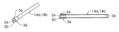
- FIGS. 4 to 6are isometric, longitudinal cross-sectional and cross-sectional views, respectively, of an extension tube of FIGS. 1 to 3 ;
- FIG. 7is an elevation view of a fitting of FIGS. 2 to 5 .
- distal and proximalrefer, respectively, to directions closer to and away from the insertion tip of a catheter in an implantable catheter assembly.
- the terminologyincludes the words specifically mentioned, derivatives thereof and words of similar import.
- the embodiments illustrated beloware not intended to be exhaustive or to limit the invention to the precise form disclosed. These embodiments are chosen and described to best explain the principle of the invention and its application and practical use and to enable others skilled in the art to best utilize the invention.
- Catheter assembly 10 in FIGS. 1 and 2includes a dual lumen catheter 12 , a pair of extension tubes 14 a , 14 b and a hub 16 , with luer fittings 18 affixed to proximal ends of the extension tubes.
- Each extension tubeis in fluid communication with a respective lumen of catheter 12 , which lumens 20 a , 20 b are of a conventional D-shaped cross-section where the lumens are separated by an internal wall or septum 22 , seen in FIG. 3 .
- Lumen 20 ais aligned with a corresponding passageway 28 a of hub 16 along a coincident axis that is also the axis of the respective extension tube 14 a , while lumen 20 b is foreshortened at 26 to enable an angled passageway 28 b of the hub to have a short portion that is coincident with the longitudinal axis of the lumen 20 b while the angled passageway portion is coincident with the axis of extension tube 14 b.
- FIG. 3also shows fittings 50 secured to the distal ends of each extension tube 14 a , 14 b , each of the fittings including an enlargement such as an annular collar 56 at the end face of the respective extension tube that protrudes radially beyond the outer diameter of the extension tube to establish a stop section securing the fitting and therefore the extension tube to the hub 16 upon insert molding of the hub to the distal ends of the extension tubes and the proximal end 24 of the catheter.
- FIG. 3also depicts that the fitting having a distal enlargement embedded within the hub proximal end portion distally of a portion of the hub is smaller in dimension than the distal enlargement of the fitting.
- FIGS. 4 and 5illustrate an extension tube 14 a , 14 b having a fitting 50 secured thereto, the fitting having a tubular proximal section 52 disposed within the passageway 34 of the extension tube and having a passageway 54 in fluid communication with passageway 34 .
- the fittingfurther includes a distal enlargement such as annular collar 56 , with annular collar 56 positioned adjacent to the end face of the extension tube and protruding radially outwardly to a diameter greater than the outer diameter of the extension tube even after the tube's distal end portion 36 has been expanded to fit over the fitting.
- the annular collarassures that the extension tube with its fitting remains mechanically anchored within and assuredly secured to the hub. Best seen in FIG.
- fitting 50extends to a proximal end 58 and is provided with at least one, preferably two or three barbs 60 therealong protruding radially outwardly.
- Fitting passageway 54extending therethrough having an inner diameter matching that of passageway 34 of the extension tube.
- Barbs 60secure the fitting in the distal end of extension tube 14 a , 14 b when fitting 50 is pressed into the distal end of the tube, with sharply angled barb faces 62 that are directed distally to prevent the extension tube from moving proximally from the fitting thereafter while gently sloping proximal faces 64 facilitate insertion of the fitting into the extension tube.
- the extension tubeis expanded slightly at distal end 36 by the fitting 50 , and grips the fitting tightly, after the fitting is pressed thereinto.
- the extension tubecomprises an inner layer 30 of substantial thickness of silicone, and a thin, outer layer 32 of polyurethane.
- the inner layer of siliconeprovides the advantages of better shape memory for the extension tube to consistently retain its intended undeformed cylindrical inner diameter even after repeatedly being clamped and unclamped by a Roberts clamp (not shown).
- the outer layer of polyurethaneassures sealing with the polyurethane hub material therearound by fusing therewith.
Landscapes
- Health & Medical Sciences (AREA)
- Engineering & Computer Science (AREA)
- Life Sciences & Earth Sciences (AREA)
- Hematology (AREA)
- Pulmonology (AREA)
- Anesthesiology (AREA)
- Biomedical Technology (AREA)
- Heart & Thoracic Surgery (AREA)
- Biophysics (AREA)
- Animal Behavior & Ethology (AREA)
- General Health & Medical Sciences (AREA)
- Public Health (AREA)
- Veterinary Medicine (AREA)
- Manufacturing & Machinery (AREA)
- Mechanical Engineering (AREA)
- Media Introduction/Drainage Providing Device (AREA)
Abstract
Description
Claims (18)
Priority Applications (1)
| Application Number | Priority Date | Filing Date | Title |
|---|---|---|---|
| US12/331,997US9572955B2 (en) | 2007-12-12 | 2008-12-10 | Catheter-to-extension tube assembly and method of making same |
Applications Claiming Priority (2)
| Application Number | Priority Date | Filing Date | Title |
|---|---|---|---|
| US738707P | 2007-12-12 | 2007-12-12 | |
| US12/331,997US9572955B2 (en) | 2007-12-12 | 2008-12-10 | Catheter-to-extension tube assembly and method of making same |
Publications (2)
| Publication Number | Publication Date |
|---|---|
| US20090157052A1 US20090157052A1 (en) | 2009-06-18 |
| US9572955B2true US9572955B2 (en) | 2017-02-21 |
Family
ID=40754232
Family Applications (1)
| Application Number | Title | Priority Date | Filing Date |
|---|---|---|---|
| US12/331,997Expired - Fee RelatedUS9572955B2 (en) | 2007-12-12 | 2008-12-10 | Catheter-to-extension tube assembly and method of making same |
Country Status (1)
| Country | Link |
|---|---|
| US (1) | US9572955B2 (en) |
Families Citing this family (9)
| Publication number | Priority date | Publication date | Assignee | Title |
|---|---|---|---|---|
| US7896853B2 (en)* | 2003-09-25 | 2011-03-01 | C. R. Bard, Inc. | Pre-molded bifurcation insert |
| US8585950B2 (en) | 2009-01-29 | 2013-11-19 | Angiodynamics, Inc. | Multilumen catheters and method of manufacturing |
| US8591450B2 (en) | 2010-06-07 | 2013-11-26 | Rex Medical L.P. | Dialysis catheter |
| US9649484B2 (en) | 2013-03-28 | 2017-05-16 | Covidien Lp | Snap connection for two tubes |
| US10625055B2 (en) | 2014-06-26 | 2020-04-21 | The Cleveland Clinic Foundation | Method and apparatus for tracking a position of a medical device |
| JP6404619B2 (en)* | 2014-06-27 | 2018-10-10 | オリンパス株式会社 | Catheter manufacturing mold and catheter manufacturing method |
| US11253266B2 (en) | 2015-08-25 | 2022-02-22 | Endoshape, Inc. | Sleeve for delivery of embolic coil |
| JP7067305B2 (en)* | 2018-06-20 | 2022-05-16 | トヨタ自動車株式会社 | Member joining method and member joining device |
| US11446467B2 (en)* | 2018-09-25 | 2022-09-20 | Smiths Medical Asd, Inc. | Overmolded septum for catheter hub |
Citations (13)
| Publication number | Priority date | Publication date | Assignee | Title |
|---|---|---|---|---|
| US4037599A (en) | 1976-01-26 | 1977-07-26 | Raulerson James D | Continuous flow catheter device |
| US4592749A (en)* | 1984-06-22 | 1986-06-03 | Gish Biomedical, Inc. | Catheter system |
| US6719330B2 (en)* | 2002-06-18 | 2004-04-13 | Qest | Flexible tubing/fitting connection |
| US20040183305A1 (en)* | 2003-02-13 | 2004-09-23 | Mark Fisher | Catheter repair coupler |
| US20040243103A1 (en)* | 2003-05-28 | 2004-12-02 | Eric King | High pressure catheter and methods for manufacturing the same |
| US20050080398A1 (en) | 2003-10-08 | 2005-04-14 | Markel David F. | Co-axial tapered catheter |
| US20050148929A1 (en)* | 2003-11-17 | 2005-07-07 | Bruce Gingles | Catheter with centering wire |
| US20050209581A1 (en)* | 2004-03-18 | 2005-09-22 | Butts M D | Catheter connector |
| US20070016167A1 (en)* | 2005-03-29 | 2007-01-18 | Smith A D | Implantable cathether and method of using same |
| US20070060866A1 (en) | 2002-10-31 | 2007-03-15 | Medical Components, Inc. | Method of attaching a hub to a multiple catheter assembly |
| US20070106261A1 (en)* | 2003-05-13 | 2007-05-10 | Dimatteo Kristian | Anti-infective central venous catheter with diffusion barrier layer |
| US20070260221A1 (en) | 2006-05-05 | 2007-11-08 | Medical Components, Inc. | Hub for triple lumen catheter assembly |
| US20090005741A1 (en) | 2007-06-29 | 2009-01-01 | Medical Components, Inc. | Closable and Openable Catheter Assembly and Method of Using Same |
- 2008
- 2008-12-10USUS12/331,997patent/US9572955B2/ennot_activeExpired - Fee Related
Patent Citations (13)
| Publication number | Priority date | Publication date | Assignee | Title |
|---|---|---|---|---|
| US4037599A (en) | 1976-01-26 | 1977-07-26 | Raulerson James D | Continuous flow catheter device |
| US4592749A (en)* | 1984-06-22 | 1986-06-03 | Gish Biomedical, Inc. | Catheter system |
| US6719330B2 (en)* | 2002-06-18 | 2004-04-13 | Qest | Flexible tubing/fitting connection |
| US20070060866A1 (en) | 2002-10-31 | 2007-03-15 | Medical Components, Inc. | Method of attaching a hub to a multiple catheter assembly |
| US20040183305A1 (en)* | 2003-02-13 | 2004-09-23 | Mark Fisher | Catheter repair coupler |
| US20070106261A1 (en)* | 2003-05-13 | 2007-05-10 | Dimatteo Kristian | Anti-infective central venous catheter with diffusion barrier layer |
| US20040243103A1 (en)* | 2003-05-28 | 2004-12-02 | Eric King | High pressure catheter and methods for manufacturing the same |
| US20050080398A1 (en) | 2003-10-08 | 2005-04-14 | Markel David F. | Co-axial tapered catheter |
| US20050148929A1 (en)* | 2003-11-17 | 2005-07-07 | Bruce Gingles | Catheter with centering wire |
| US20050209581A1 (en)* | 2004-03-18 | 2005-09-22 | Butts M D | Catheter connector |
| US20070016167A1 (en)* | 2005-03-29 | 2007-01-18 | Smith A D | Implantable cathether and method of using same |
| US20070260221A1 (en) | 2006-05-05 | 2007-11-08 | Medical Components, Inc. | Hub for triple lumen catheter assembly |
| US20090005741A1 (en) | 2007-06-29 | 2009-01-01 | Medical Components, Inc. | Closable and Openable Catheter Assembly and Method of Using Same |
Also Published As
| Publication number | Publication date |
|---|---|
| US20090157052A1 (en) | 2009-06-18 |
Similar Documents
| Publication | Publication Date | Title |
|---|---|---|
| US9572955B2 (en) | Catheter-to-extension tube assembly and method of making same | |
| US8226633B2 (en) | Method of making a co-axial catheter | |
| US8852168B2 (en) | Connection system for multi-lumen catheter | |
| US7740780B2 (en) | Multitube catheter and method for making the same | |
| EP1622667B1 (en) | Multilumen vascular catheter and method for manufacturing the same | |
| US8357127B2 (en) | Pre-molded bifurcation insert | |
| US8147452B2 (en) | Method of joining a hub to an introducer sheath tube | |
| US7938806B2 (en) | Tearaway introducer sheath with hemostasis valve | |
| EP1699517B1 (en) | Reinforced multi-lumen catheter | |
| US8585950B2 (en) | Multilumen catheters and method of manufacturing | |
| EP1915188B1 (en) | Catheter having staggered lumen | |
| US20090247987A1 (en) | Drainage Catheter | |
| CN219355042U (en) | Catheter tube | |
| CN219251344U (en) | Catheter tube | |
| US11439791B2 (en) | Catheter and manufacturing method of catheter | |
| EP1628700B1 (en) | High pressure catheter and methods for manufacturing the same | |
| US20210031021A1 (en) | Medical tube | |
| US12383718B2 (en) | Tube connector for medical tube lines | |
| CN219921793U (en) | Center catheter, center catheter assembly, and center catheter hub | |
| JP2016067457A (en) | Method of manufacturing tracheal tube, and tracheal tube |
Legal Events
| Date | Code | Title | Description |
|---|---|---|---|
| AS | Assignment | Owner name:MEDICAL COMPONENTS, INC., PENNSYLVANIA Free format text:ASSIGNMENT OF ASSIGNORS INTEREST;ASSIGNOR:NARDEO, MAHASE;REEL/FRAME:022330/0176 Effective date:20090213 | |
| AS | Assignment | Owner name:MEDICAL COMPONENTS, INC., PENNSYLVANIA Free format text:ASSIGNMENT OF ASSIGNORS INTEREST;ASSIGNOR:VERBITSKY, GARY;REEL/FRAME:040033/0171 Effective date:20080411 | |
| STCF | Information on status: patent grant | Free format text:PATENTED CASE | |
| MAFP | Maintenance fee payment | Free format text:PAYMENT OF MAINTENANCE FEE, 4TH YEAR, LARGE ENTITY (ORIGINAL EVENT CODE: M1551); ENTITY STATUS OF PATENT OWNER: LARGE ENTITY Year of fee payment:4 | |
| FEPP | Fee payment procedure | Free format text:MAINTENANCE FEE REMINDER MAILED (ORIGINAL EVENT CODE: REM.); ENTITY STATUS OF PATENT OWNER: LARGE ENTITY | |
| LAPS | Lapse for failure to pay maintenance fees | Free format text:PATENT EXPIRED FOR FAILURE TO PAY MAINTENANCE FEES (ORIGINAL EVENT CODE: EXP.); ENTITY STATUS OF PATENT OWNER: LARGE ENTITY | |
| STCH | Information on status: patent discontinuation | Free format text:PATENT EXPIRED DUE TO NONPAYMENT OF MAINTENANCE FEES UNDER 37 CFR 1.362 | |
| FP | Lapsed due to failure to pay maintenance fee | Effective date:20250221 |