US9572621B2 - Surgical jaws for sealing tissue - Google Patents
Surgical jaws for sealing tissueDownload PDFInfo
- Publication number
- US9572621B2 US9572621B2US12/792,201US79220110AUS9572621B2US 9572621 B2US9572621 B2US 9572621B2US 79220110 AUS79220110 AUS 79220110AUS 9572621 B2US9572621 B2US 9572621B2
- Authority
- US
- United States
- Prior art keywords
- wire element
- teeth
- jaws
- surgical tool
- tool assembly
- Prior art date
- Legal status (The legal status is an assumption and is not a legal conclusion. Google has not performed a legal analysis and makes no representation as to the accuracy of the status listed.)
- Active, expires
Links
- 238000007789sealingMethods0.000titledescription2
- 230000007246mechanismEffects0.000claimsdescription12
- 239000012811non-conductive materialSubstances0.000claimsdescription7
- 239000004020conductorSubstances0.000claimsdescription6
- 239000007787solidSubstances0.000claimsdescription2
- 230000000295complement effectEffects0.000claims1
- 230000000712assemblyEffects0.000description6
- 238000000429assemblyMethods0.000description6
- 230000015271coagulationEffects0.000description5
- 238000005345coagulationMethods0.000description5
- 238000000034methodMethods0.000description4
- 230000008901benefitEffects0.000description2
- 210000004204blood vesselAnatomy0.000description2
- 239000000919ceramicSubstances0.000description2
- 239000002184metalSubstances0.000description2
- 239000004033plasticSubstances0.000description2
- 229920003023plasticPolymers0.000description2
- 230000001112coagulating effectEffects0.000description1
- 239000011248coating agentSubstances0.000description1
- 238000000576coating methodMethods0.000description1
- 230000007812deficiencyEffects0.000description1
- 238000012986modificationMethods0.000description1
- 230000004048modificationEffects0.000description1
- 230000004044responseEffects0.000description1
- 238000001356surgical procedureMethods0.000description1
Images


Classifications
- A—HUMAN NECESSITIES
- A61—MEDICAL OR VETERINARY SCIENCE; HYGIENE
- A61B—DIAGNOSIS; SURGERY; IDENTIFICATION
- A61B18/00—Surgical instruments, devices or methods for transferring non-mechanical forms of energy to or from the body
- A61B18/04—Surgical instruments, devices or methods for transferring non-mechanical forms of energy to or from the body by heating
- A61B18/12—Surgical instruments, devices or methods for transferring non-mechanical forms of energy to or from the body by heating by passing a current through the tissue to be heated, e.g. high-frequency current
- A61B18/14—Probes or electrodes therefor
- A61B18/1442—Probes having pivoting end effectors, e.g. forceps
- A—HUMAN NECESSITIES
- A61—MEDICAL OR VETERINARY SCIENCE; HYGIENE
- A61B—DIAGNOSIS; SURGERY; IDENTIFICATION
- A61B17/00—Surgical instruments, devices or methods
- A61B17/32—Surgical cutting instruments
- A61B17/320016—Endoscopic cutting instruments, e.g. arthroscopes, resectoscopes
- A—HUMAN NECESSITIES
- A61—MEDICAL OR VETERINARY SCIENCE; HYGIENE
- A61B—DIAGNOSIS; SURGERY; IDENTIFICATION
- A61B18/00—Surgical instruments, devices or methods for transferring non-mechanical forms of energy to or from the body
- A61B18/04—Surgical instruments, devices or methods for transferring non-mechanical forms of energy to or from the body by heating
- A61B18/12—Surgical instruments, devices or methods for transferring non-mechanical forms of energy to or from the body by heating by passing a current through the tissue to be heated, e.g. high-frequency current
- A61B18/14—Probes or electrodes therefor
- A61B18/148—Probes or electrodes therefor having a short, rigid shaft for accessing the inner body transcutaneously, e.g. for neurosurgery or arthroscopy
- A—HUMAN NECESSITIES
- A61—MEDICAL OR VETERINARY SCIENCE; HYGIENE
- A61B—DIAGNOSIS; SURGERY; IDENTIFICATION
- A61B17/00—Surgical instruments, devices or methods
- A61B17/28—Surgical forceps
- A61B17/2812—Surgical forceps with a single pivotal connection
- A61B17/282—Jaws
- A61B2017/2825—Inserts of different material in jaws
- A—HUMAN NECESSITIES
- A61—MEDICAL OR VETERINARY SCIENCE; HYGIENE
- A61B—DIAGNOSIS; SURGERY; IDENTIFICATION
- A61B17/00—Surgical instruments, devices or methods
- A61B17/28—Surgical forceps
- A61B17/29—Forceps for use in minimally invasive surgery
- A61B2017/2926—Details of heads or jaws
- A61B2017/2932—Transmission of forces to jaw members
- A61B2017/2933—Transmission of forces to jaw members camming or guiding means
- A—HUMAN NECESSITIES
- A61—MEDICAL OR VETERINARY SCIENCE; HYGIENE
- A61B—DIAGNOSIS; SURGERY; IDENTIFICATION
- A61B18/00—Surgical instruments, devices or methods for transferring non-mechanical forms of energy to or from the body
- A61B2018/00053—Mechanical features of the instrument of device
- A61B2018/00059—Material properties
- A61B2018/00071—Electrical conductivity
- A61B2018/00083—Electrical conductivity low, i.e. electrically insulating
- A—HUMAN NECESSITIES
- A61—MEDICAL OR VETERINARY SCIENCE; HYGIENE
- A61B—DIAGNOSIS; SURGERY; IDENTIFICATION
- A61B18/00—Surgical instruments, devices or methods for transferring non-mechanical forms of energy to or from the body
- A61B2018/00571—Surgical instruments, devices or methods for transferring non-mechanical forms of energy to or from the body for achieving a particular surgical effect
- A61B2018/0063—Sealing
- A—HUMAN NECESSITIES
- A61—MEDICAL OR VETERINARY SCIENCE; HYGIENE
- A61B—DIAGNOSIS; SURGERY; IDENTIFICATION
- A61B18/00—Surgical instruments, devices or methods for transferring non-mechanical forms of energy to or from the body
- A61B18/04—Surgical instruments, devices or methods for transferring non-mechanical forms of energy to or from the body by heating
- A61B18/12—Surgical instruments, devices or methods for transferring non-mechanical forms of energy to or from the body by heating by passing a current through the tissue to be heated, e.g. high-frequency current
- A61B18/14—Probes or electrodes therefor
- A61B2018/1405—Electrodes having a specific shape
- A61B2018/1412—Blade
- A—HUMAN NECESSITIES
- A61—MEDICAL OR VETERINARY SCIENCE; HYGIENE
- A61B—DIAGNOSIS; SURGERY; IDENTIFICATION
- A61B18/00—Surgical instruments, devices or methods for transferring non-mechanical forms of energy to or from the body
- A61B18/04—Surgical instruments, devices or methods for transferring non-mechanical forms of energy to or from the body by heating
- A61B18/12—Surgical instruments, devices or methods for transferring non-mechanical forms of energy to or from the body by heating by passing a current through the tissue to be heated, e.g. high-frequency current
- A61B18/14—Probes or electrodes therefor
- A61B18/1442—Probes having pivoting end effectors, e.g. forceps
- A61B2018/1452—Probes having pivoting end effectors, e.g. forceps including means for cutting
- A61B2018/1455—Probes having pivoting end effectors, e.g. forceps including means for cutting having a moving blade for cutting tissue grasped by the jaws
- A—HUMAN NECESSITIES
- A61—MEDICAL OR VETERINARY SCIENCE; HYGIENE
- A61B—DIAGNOSIS; SURGERY; IDENTIFICATION
- A61B18/00—Surgical instruments, devices or methods for transferring non-mechanical forms of energy to or from the body
- A61B18/04—Surgical instruments, devices or methods for transferring non-mechanical forms of energy to or from the body by heating
- A61B18/12—Surgical instruments, devices or methods for transferring non-mechanical forms of energy to or from the body by heating by passing a current through the tissue to be heated, e.g. high-frequency current
- A61B18/14—Probes or electrodes therefor
- A61B2018/1497—Electrodes covering only part of the probe circumference
Definitions
- the subject inventionrelates generally to surgical jaws for grasping and sealing tissue.
- Surgical tool assemblies for coagulating and cutting tissuehave greatly improved modern surgical techniques and are well known in the art.
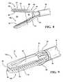
- Such tool assembliestypically include a pair of jaws formed of wire for delivering electrical energy to the tissue, as shown in FIG. 2 .
- the jawseach include a plurality of teeth for grasping the tissue and providing the energy to the tissue.
- a bladeis often disposed adjacent to the jaws for cutting the tissue.
- the subject inventionis directed toward these and other deficiencies of the prior art.
- the subject disclosureprovides a surgical tool assembly for use in electrosurgery.
- the assemblyincludes an elongated sheath movable in a longitudinal direction.
- a pair of jawseach includes a plurality of teeth for grasping tissue and a support element supporting the plurality of teeth.
- the support elementis disposed partially within the sheath and extends to a distal end disposed outside of the sheath.
- the support elementincludes a first portion extending from the distal end and delineating a first region.
- the support elementfurther includes a second portion extending from the first portion and delineating a second region.
- the second portionis curved to engage with the sheath such that the jaws move towards one another as the elongated sheath moves towards the distal end.
- the teethextend from the first region into the second region.
- the performance of the jawsis enhanced. Specifically, the grasping, coagulation, and cutting length is extended over jaw assemblies of the prior art. Furthermore, this extension of the teeth into the second region eliminates the bulging of tissue under one or all of the curvatures of the jaws. This improves overall coagulation of the tissue.
- FIG. 1is a perspective view of a surgical tool assembly including a handle mechanism operatively connected to a pair of jaws;
- FIG. 2is a perspective view of the pair of jaws according to the prior art
- FIG. 3is a perspective view of a first embodiment of the pair of jaws
- FIG. 4is a side view of the first embodiment of the pair of jaws
- FIG. 5is a top view of the first embodiment of the pair of jaws
- FIG. 6is a perspective view of a second embodiment of the pair of jaws in an open position
- FIG. 7is a perspective view of the second embodiment of the pair of jaws in a closed position
- FIG. 8is a perspective view of a third embodiment of the pair of jaws.
- FIG. 9is a perspective view of a fourth embodiment of the pair of jaws.
- a surgical tool assembly 10 for use in electrosurgeryis shown herein.
- the surgical tool assembly 10includes a pair of jaws 12 a , 12 b , i.e., a first jaw 12 a and a second jaw 12 b , for grasping tissue (not shown), such as a blood vessel.
- each jaw 12 a , 12 bis movable.
- the first jaw 12 amay be fixed while the second jaw 12 b is movable, or vice-versa.
- the first jaw 12 a and the second jaw 12 bare arranged as mirror images of one another, i.e., the jaws 12 a , 12 b each have the same general design feature.
- a non-symmetrical arrangement of the jaws 12 a , 12 bis not always necessary and that one of the jaws 12 a , 12 b may have different feature from the other jaw 12 .
- the surgical tool assembly 10may include a handle mechanism 14 for controlling operation of the jaws 12 a , 12 b as well as performing other functions of the assembly 10 , as shown in FIG. 1 .
- the handle mechanism 14 of the illustrated embodimentincludes a trigger 16 operatively connected to the jaws 12 a , 12 b.
- the assembly 10also includes an elongated sheath 18 .
- the elongated sheath 18 of the illustrated embodimentextends away from the handle mechanism 14 .
- the elongated sheath 18is movable in a longitudinal direction, i.e., back-and-forth along a longitudinal axis (not specifically shown).
- the elongated sheath 18is operatively connected to the trigger 16 to control the jaws 12 a , 12 b , as will be detailed further herein.
- the elongated sheath 18defines an opening (not numbered).
- the sheath 18defines a tubular shape, i.e., the sheath 18 has a circular cross section with a hollow interior (not numbered).
- the sheath 18may be utilized within the scope of the present invention.
- the jaws 12 a , 12 beach include a plurality of teeth 20 and a support element 22 .
- the teeth 20are typically utilized for grasping the tissue while the support element 22 supports the teeth 20 .
- the teeth 20 of the illustrated embodimentinclude a plurality of projections 24 and a plurality of recesses 26 alternating with one another.
- the teeth 20are serrated, i.e., the projections 24 are pointed.
- those skilled in the artrealize alternative designs to implement the projection 24 and recesses 26 .
- the support element 22is disposed partially within the sheath 18 .
- the support element 22extends to a distal end 28 disposed outside of the sheath 18 .
- the support element 22has a proximal end (not shown) that terminates within the handle mechanism 14 .
- the support element 22may be implemented as a rigid wire (not numbered), as best seen in FIGS. 3-6, 8, and 9 . Said another way, the support element 22 is generally solid and forms a circular cross section. Of course, other suitable designs for the support element 22 will be realized by those skilled in the art.
- the support element 22is preferably formed of an electrically conductive material as discussed further below.
- each support element 22includes a pair of legs 30 , as best seen in FIG. 5 .
- the legs 30are coupled together at the distal end 28 .
- the legs 30are formed of a continuous wire which wraps around and changes direction at the distal end 28 .
- the support element 22may be implemented as a single piece (not shown) and not the separate legs 30 .
- the legs 30 of the illustrated embodimentsdefine a channel 32 therebetween.
- the assembly 10 of the illustrated embodimentsincludes a blade 34 movable in the longitudinal direction and disposed in the channel 32 .
- the blade 34is preferably supported by a wire (not shown) which extends through the sheath 18 and into the handle mechanism 14 .
- the blade 34may be operated, i.e., moved back and forth, via a lever or trigger (not numbered) on the handle mechanism 14 .
- the jaws 12 a , 12 bare formed of an electrically conductive material, such as a metal.
- the jaws 12 a , 12 bmay be electrically connected to an electrical power source (not shown) for delivering electric current to the tissue.
- an electrical power source(not shown) for delivering electric current to the tissue.
- the blade 34is also preferably formed of an electrically conductive material, such as a metal, and may also be electrically connected to the power source.
- the electrical power sourcemay be connected to a connector (not numbered) disposed on the handle mechanism 14 .
- the electric currentis then routed through conductors (not shown) within the handle mechanism 14 and to the support elements 22 .
- the support elements 22are electrically connected to the teeth 20 , such that the electric current may conduct through the teeth 20 .
- the electric currentmay be delivered to the tissue using monopolar and/or bipolar techniques, as is well known to those skilled in the art.
- the monopolar techniquethe electric current is delivered using at least one of the jaws 12 a , 12 b and/or the blade.
- a conductive pad(not shown) in contact with the patient provides a return path for the current.
- the bipolar techniquethe electric current conducts from the first jaw 12 a to the second jaw 12 b , from both jaws 12 a , 12 b to the blade 34 , or from one of the jaws 12 a , 12 b to the blade 34 .
- At least one of the jaws 12 a , 12 bis at least partially covered by a non-conductive material 35 .
- the non-conductive materialmay cover at least part of the support element 22 of each jaw 12 .
- the non-conductive materialdoes not interrupt the electrical connection between the support element 22 and the teeth 20 .
- the non-conductive material 35is extending to a point (not numbered) adjacent to the distal end 28 of each jaw 12 a , 12 b . As such, the electric current is prevented from flowing from most of the support element 22 to the surrounding tissue. This minimizes the amount of tissue that is exposed to the electric current and provides safety to monopolar applications.
- the non-conductive material 35may be a dielectric coating (not separately numbered) that is applied to portions of the jaws 12 a , 12 b , as shown in the Figures.
- An insulated applique 36as shown in FIG. 8 , may also be connected to the support element 22 .
- the applique 36 in the illustrated embodimentis formed of plastic. However, other non-conductive materials may also be suitable, including, but not limited to, ceramics or ceramic plastics.
- the support element 22includes a first portion 37 extending to the distal end 28 .
- the support element 22also includes a second portion 40 extending to the first portion 37 .
- the regions 38 and 42are separated, as indicated by the dashed line, by the juncture between a first area between the first portions 37 and a second area between the second portions 40 of the support element 22 .
- the second portion 40 of the support element 22is curved to engage with the sheath 18 .
- the back-and-forth movement of the sheath 18engages with the second portion 40 of the support element 22 and regulates movement of the support elements 22 , and accordingly, the jaws 12 a , 12 b .
- the curve of the support element 22is such that the jaws 12 a , 12 b move towards one another as the sheath 18 moves towards the distal end 28 of the support element 22 .
- the second portion 40 of the jaws 12 a , 12 bdefines a first curvature 44 and a second curvature 46 .
- the first curvature 44 of the first jaw 12 abulges towards the first curvature 44 of the second jaw 12 b , and vice versa.
- the first curvature 44provides a gradual slope which causes a gradual closure of the jaws 12 a , 12 b in response to advancement of the sheath 18 toward the distal end 28 .
- the second curvature 46 of the first jaw 12 abulges away from the second curvature 46 of the second jaw 12 b , and vice versa.
- the second curvature 46provides a “hump” for providing the final movement of the jaws 12 a , 12 b into the closed position as well as rigidity at the end of the movement of the sheath 18 .
- the teeth 20are disposed in both the first region 38 and the second region 42 . That is, as the teeth 20 are supported at least by the first portion 37 of each jaw of the support element 22 , the teeth 20 extend into the first region 38 and the second region 42 . Said another way, the teeth 20 are disposed adjacent to at least part of the first portion 37 and at least part of the second portion 40 . Said yet another way, the teeth 20 are positioned underneath at least one of the curvatures 44 , 46 of the second portion 40 of the first jaw 12 a in addition to being positioned underneath the first portion 37 . Also, the teeth 20 are positioned above at least one of the curvatures 44 , 46 of the second portion 40 of the second jaw 12 b in addition to being positioned above the first portion 37 .
- the performance of the jaws 12 a , 12 bis enhanced. Specifically, the grasping, coagulation, and cutting length is extended by approximately 25-35% over jaw assemblies of the prior art. Furthermore, the expansion of the teeth 20 into the second region 42 eliminates the bulging of tissue under one or all of the curvatures 44 , 46 that often occurs in prior art jaw assemblies.
- the teeth 20are attached to both the first and second portions 37 , 40 of the support element 22 .
- the teeth 20are attached only to the first portion 37 of the support element 22 , yet extend into the second region 42 .
- the second portion 40 of the support element 22retains much of the flexibility of the prior art jaw assemblies.
- the assembly 10may also include tip 48 disposed at the distal end 28 of each of the jaws 12 a , 12 b .
- the tips 48are disposed to engage one another when the jaws 12 a , 12 b are in the closed position. (See FIG. 7 .)
- the tips 48may prevent the teeth 20 of the first jaw 12 a from meshing with the teeth 20 of the second jaw 12 b , and vice versa. That is, the tips 48 may prevent closure of the jaws 12 a , 12 b past the closed position.
Landscapes
- Health & Medical Sciences (AREA)
- Surgery (AREA)
- Engineering & Computer Science (AREA)
- Life Sciences & Earth Sciences (AREA)
- Biomedical Technology (AREA)
- Otolaryngology (AREA)
- Nuclear Medicine, Radiotherapy & Molecular Imaging (AREA)
- Plasma & Fusion (AREA)
- Physics & Mathematics (AREA)
- Heart & Thoracic Surgery (AREA)
- Medical Informatics (AREA)
- Molecular Biology (AREA)
- Animal Behavior & Ethology (AREA)
- General Health & Medical Sciences (AREA)
- Public Health (AREA)
- Veterinary Medicine (AREA)
- Surgical Instruments (AREA)
Abstract
Description
Claims (21)
Priority Applications (1)
| Application Number | Priority Date | Filing Date | Title |
|---|---|---|---|
| US12/792,201US9572621B2 (en) | 2009-06-02 | 2010-06-02 | Surgical jaws for sealing tissue |
Applications Claiming Priority (2)
| Application Number | Priority Date | Filing Date | Title |
|---|---|---|---|
| US18312409P | 2009-06-02 | 2009-06-02 | |
| US12/792,201US9572621B2 (en) | 2009-06-02 | 2010-06-02 | Surgical jaws for sealing tissue |
Publications (2)
| Publication Number | Publication Date |
|---|---|
| US20100305564A1 US20100305564A1 (en) | 2010-12-02 |
| US9572621B2true US9572621B2 (en) | 2017-02-21 |
Family
ID=42338317
Family Applications (1)
| Application Number | Title | Priority Date | Filing Date |
|---|---|---|---|
| US12/792,201Active2033-04-17US9572621B2 (en) | 2009-06-02 | 2010-06-02 | Surgical jaws for sealing tissue |
Country Status (4)
| Country | Link |
|---|---|
| US (1) | US9572621B2 (en) |
| EP (1) | EP2437674B1 (en) |
| CN (2) | CN104605929B (en) |
| WO (1) | WO2010141083A1 (en) |
Cited By (1)
| Publication number | Priority date | Publication date | Assignee | Title |
|---|---|---|---|---|
| US20170119415A1 (en)* | 2015-10-28 | 2017-05-04 | Covidien Lp | Surgical instruments including knife assemblies with reducible cutting height |
Families Citing this family (35)
| Publication number | Priority date | Publication date | Assignee | Title |
|---|---|---|---|---|
| US11090104B2 (en) | 2009-10-09 | 2021-08-17 | Cilag Gmbh International | Surgical generator for ultrasonic and electrosurgical devices |
| DE102012202434A1 (en)* | 2012-02-17 | 2013-08-22 | Geuder Ag | Medical instrument |
| US9408622B2 (en) | 2012-06-29 | 2016-08-09 | Ethicon Endo-Surgery, Llc | Surgical instruments with articulating shafts |
| CN103110458A (en)* | 2013-02-09 | 2013-05-22 | 王玉萍 | Bipolar coagulation forceps |
| DE102013004652B4 (en)* | 2013-03-16 | 2014-10-30 | Zahoransky Ag | Device for producing surgical clips bent from wire sections |
| CN106535801B (en)* | 2014-04-02 | 2020-09-04 | 美国奥林匹斯外科技术吉鲁斯阿克米公司 | Surgical device with replaceable elements |
| CN107530126B (en) | 2015-04-10 | 2020-12-15 | 捷锐士阿希迈公司(以奥林巴斯美国外科技术名义) | Medical tweezers with offset teeth |
| US10194973B2 (en) | 2015-09-30 | 2019-02-05 | Ethicon Llc | Generator for digitally generating electrical signal waveforms for electrosurgical and ultrasonic surgical instruments |
| US11129670B2 (en) | 2016-01-15 | 2021-09-28 | Cilag Gmbh International | Modular battery powered handheld surgical instrument with selective application of energy based on button displacement, intensity, or local tissue characterization |
| US11051840B2 (en) | 2016-01-15 | 2021-07-06 | Ethicon Llc | Modular battery powered handheld surgical instrument with reusable asymmetric handle housing |
| US11229471B2 (en) | 2016-01-15 | 2022-01-25 | Cilag Gmbh International | Modular battery powered handheld surgical instrument with selective application of energy based on tissue characterization |
| US12193698B2 (en) | 2016-01-15 | 2025-01-14 | Cilag Gmbh International | Method for self-diagnosing operation of a control switch in a surgical instrument system |
| US11419666B2 (en)* | 2016-04-04 | 2022-08-23 | Gyrus Acmi, Inc. | Advanced leverage instrument |
| US11266430B2 (en) | 2016-11-29 | 2022-03-08 | Cilag Gmbh International | End effector control and calibration |
| IL269091B2 (en) | 2017-03-08 | 2024-04-01 | Momentis Surgical Ltd | Electrosurgery device |
| US11350977B2 (en)* | 2017-03-08 | 2022-06-07 | Memic Innovative Surgery Ltd. | Modular electrosurgical device |
| US11944366B2 (en) | 2019-12-30 | 2024-04-02 | Cilag Gmbh International | Asymmetric segmented ultrasonic support pad for cooperative engagement with a movable RF electrode |
| US12343063B2 (en) | 2019-12-30 | 2025-07-01 | Cilag Gmbh International | Multi-layer clamp arm pad for enhanced versatility and performance of a surgical device |
| US12262937B2 (en) | 2019-12-30 | 2025-04-01 | Cilag Gmbh International | User interface for surgical instrument with combination energy modality end-effector |
| US11786294B2 (en) | 2019-12-30 | 2023-10-17 | Cilag Gmbh International | Control program for modular combination energy device |
| US12082808B2 (en) | 2019-12-30 | 2024-09-10 | Cilag Gmbh International | Surgical instrument comprising a control system responsive to software configurations |
| US11812957B2 (en) | 2019-12-30 | 2023-11-14 | Cilag Gmbh International | Surgical instrument comprising a signal interference resolution system |
| US11779387B2 (en) | 2019-12-30 | 2023-10-10 | Cilag Gmbh International | Clamp arm jaw to minimize tissue sticking and improve tissue control |
| US20210196357A1 (en)* | 2019-12-30 | 2021-07-01 | Ethicon Llc | Electrosurgical instrument with asynchronous energizing electrodes |
| US12076006B2 (en) | 2019-12-30 | 2024-09-03 | Cilag Gmbh International | Surgical instrument comprising an orientation detection system |
| US11986201B2 (en) | 2019-12-30 | 2024-05-21 | Cilag Gmbh International | Method for operating a surgical instrument |
| US11950797B2 (en) | 2019-12-30 | 2024-04-09 | Cilag Gmbh International | Deflectable electrode with higher distal bias relative to proximal bias |
| US11786291B2 (en) | 2019-12-30 | 2023-10-17 | Cilag Gmbh International | Deflectable support of RF energy electrode with respect to opposing ultrasonic blade |
| CN114901186A (en)* | 2019-12-30 | 2022-08-12 | 西拉格国际有限公司 | Electrosurgical instrument with electrode bias support |
| US12053224B2 (en) | 2019-12-30 | 2024-08-06 | Cilag Gmbh International | Variation in electrode parameters and deflectable electrode to modify energy density and tissue interaction |
| US11937866B2 (en) | 2019-12-30 | 2024-03-26 | Cilag Gmbh International | Method for an electrosurgical procedure |
| US12336747B2 (en) | 2019-12-30 | 2025-06-24 | Cilag Gmbh International | Method of operating a combination ultrasonic / bipolar RF surgical device with a combination energy modality end-effector |
| US12023086B2 (en) | 2019-12-30 | 2024-07-02 | Cilag Gmbh International | Electrosurgical instrument for delivering blended energy modalities to tissue |
| US11937863B2 (en) | 2019-12-30 | 2024-03-26 | Cilag Gmbh International | Deflectable electrode with variable compression bias along the length of the deflectable electrode |
| CN114376674B (en)* | 2021-12-31 | 2025-01-21 | 杭州德柯医疗科技有限公司 | Stable puncture clamp |
Citations (32)
| Publication number | Priority date | Publication date | Assignee | Title |
|---|---|---|---|---|
| US5226908A (en) | 1989-12-05 | 1993-07-13 | Inbae Yoon | Multi-functional instruments and stretchable ligating and occluding devices |
| US5318589A (en)* | 1992-04-15 | 1994-06-07 | Microsurge, Inc. | Surgical instrument for endoscopic surgery |
| WO1995007662A1 (en) | 1993-09-14 | 1995-03-23 | Microsurge, Inc. | Endoscopic surgical instrument with guided jaws and ratchet control |
| US5443479A (en) | 1994-02-07 | 1995-08-22 | Bressi, Jr.; Thomas E. | Surgical forceps |
| US5458598A (en)* | 1993-12-02 | 1995-10-17 | Cabot Technology Corporation | Cutting and coagulating forceps |
| US5507297A (en) | 1991-04-04 | 1996-04-16 | Symbiosis Corporation | Endoscopic instruments having detachable proximal handle and distal portions |
| US5603723A (en) | 1995-01-11 | 1997-02-18 | United States Surgical Corporation | Surgical instrument configured to be disassembled for cleaning |
| US5611808A (en)* | 1995-09-12 | 1997-03-18 | Cabot Technology Corporation | Blade assembly receptacle and method |
| US5735849A (en)* | 1996-11-07 | 1998-04-07 | Everest Medical Corporation | Endoscopic forceps with thumb-slide lock release mechanism |
| US5800449A (en) | 1997-03-11 | 1998-09-01 | Ethicon Endo-Surgery, Inc. | Knife shield for surgical instruments |
| US5820630A (en) | 1996-10-22 | 1998-10-13 | Annex Medical, Inc. | Medical forceps jaw assembly |
| US5984939A (en)* | 1989-12-05 | 1999-11-16 | Yoon; Inbae | Multifunctional grasping instrument with cutting member and operating channel for use in endoscopic and non-endoscopic procedures |
| US6099550A (en) | 1989-12-05 | 2000-08-08 | Yoon; Inbae | Surgical instrument having jaws and an operating channel and method for use thereof |
| US6261308B1 (en) | 1999-08-09 | 2001-07-17 | Carlos A. Saavedra | Medical forceps for vascular surgery |
| US6270497B1 (en) | 1998-08-27 | 2001-08-07 | Olympus Optical Co., Ltd. | High-frequency treatment apparatus having control mechanism for incising tissue after completion of coagulation by high-frequency treatment tool |
| US6419675B1 (en)* | 1999-09-03 | 2002-07-16 | Conmed Corporation | Electrosurgical coagulating and cutting instrument |
| US6458128B1 (en)* | 2001-01-24 | 2002-10-01 | Ethicon, Inc. | Electrosurgical instrument with a longitudinal element for conducting RF energy and moving a cutting element |
| US20030191464A1 (en) | 2002-04-09 | 2003-10-09 | Pentax Corporation | Endoscopic forceps instrument |
| US6679882B1 (en)* | 1998-06-22 | 2004-01-20 | Lina Medical Aps | Electrosurgical device for coagulating and for making incisions, a method of severing blood vessels and a method of coagulating and for making incisions in or severing tissue |
| EP1433428A1 (en) | 2002-08-02 | 2004-06-30 | Olympus Corporation | Ultrasonic treatment apparatus |
| US20040254573A1 (en) | 2003-06-13 | 2004-12-16 | Dycus Sean T. | Vessel sealer and divider for use with small trocars and cannulas |
| US20050124987A1 (en) | 2003-12-09 | 2005-06-09 | Gyrus Medical Limited | Surgical instrument |
| US20050165443A1 (en)* | 2004-01-26 | 2005-07-28 | Steve Livneh | Multi-mode surgical instrument |
| US20080015566A1 (en) | 2006-07-13 | 2008-01-17 | Steve Livneh | Surgical sealing and cutting apparatus |
| US20080154299A1 (en) | 2006-12-08 | 2008-06-26 | Steve Livneh | Forceps for performing endoscopic surgery |
| US20080208246A1 (en) | 2007-02-08 | 2008-08-28 | Steve Livneh | Modular electrosurgical adaptors and multi function active shafts for use in electrosurgical instruments |
| US20080294159A1 (en)* | 2007-05-25 | 2008-11-27 | Kazuya Akahoshi | High frequency surgical instrument |
| CN201168050Y (en) | 2008-03-31 | 2008-12-24 | 郑森华 | Double-pole bending separation clamp |
| US20090209959A1 (en) | 2006-02-14 | 2009-08-20 | Volker Bartel | Electrosurgical instrument and type series for electrosurgical instruments |
| US20100057081A1 (en)* | 2008-08-28 | 2010-03-04 | Tyco Healthcare Group Lp | Tissue Fusion Jaw Angle Improvement |
| US7815641B2 (en)* | 2006-01-25 | 2010-10-19 | The Regents Of The University Of Michigan | Surgical instrument and method for use thereof |
| US20100292690A1 (en) | 2009-03-02 | 2010-11-18 | Bovie Medical Corporation | Surgical apparatus for tissue sealing and cutting |
- 2010
- 2010-06-02USUS12/792,201patent/US9572621B2/enactiveActive
- 2010-06-02CNCN201510025988.1Apatent/CN104605929B/enactiveActive
- 2010-06-02EPEP10727184.3Apatent/EP2437674B1/enactiveActive
- 2010-06-02CNCN201080030944.3Apatent/CN102458291B/enactiveActive
- 2010-06-02WOPCT/US2010/001607patent/WO2010141083A1/enactiveApplication Filing
Patent Citations (33)
| Publication number | Priority date | Publication date | Assignee | Title |
|---|---|---|---|---|
| US5984939A (en)* | 1989-12-05 | 1999-11-16 | Yoon; Inbae | Multifunctional grasping instrument with cutting member and operating channel for use in endoscopic and non-endoscopic procedures |
| US5226908A (en) | 1989-12-05 | 1993-07-13 | Inbae Yoon | Multi-functional instruments and stretchable ligating and occluding devices |
| US6099550A (en) | 1989-12-05 | 2000-08-08 | Yoon; Inbae | Surgical instrument having jaws and an operating channel and method for use thereof |
| US5507297A (en) | 1991-04-04 | 1996-04-16 | Symbiosis Corporation | Endoscopic instruments having detachable proximal handle and distal portions |
| US5318589A (en)* | 1992-04-15 | 1994-06-07 | Microsurge, Inc. | Surgical instrument for endoscopic surgery |
| WO1995007662A1 (en) | 1993-09-14 | 1995-03-23 | Microsurge, Inc. | Endoscopic surgical instrument with guided jaws and ratchet control |
| US5499998A (en) | 1993-09-14 | 1996-03-19 | Microsurge, Inc. | Endoscoptic surgical instrument with guided jaws and ratchet control |
| US5458598A (en)* | 1993-12-02 | 1995-10-17 | Cabot Technology Corporation | Cutting and coagulating forceps |
| US5443479A (en) | 1994-02-07 | 1995-08-22 | Bressi, Jr.; Thomas E. | Surgical forceps |
| US5603723A (en) | 1995-01-11 | 1997-02-18 | United States Surgical Corporation | Surgical instrument configured to be disassembled for cleaning |
| US5611808A (en)* | 1995-09-12 | 1997-03-18 | Cabot Technology Corporation | Blade assembly receptacle and method |
| US5820630A (en) | 1996-10-22 | 1998-10-13 | Annex Medical, Inc. | Medical forceps jaw assembly |
| US5735849A (en)* | 1996-11-07 | 1998-04-07 | Everest Medical Corporation | Endoscopic forceps with thumb-slide lock release mechanism |
| US5800449A (en) | 1997-03-11 | 1998-09-01 | Ethicon Endo-Surgery, Inc. | Knife shield for surgical instruments |
| US6679882B1 (en)* | 1998-06-22 | 2004-01-20 | Lina Medical Aps | Electrosurgical device for coagulating and for making incisions, a method of severing blood vessels and a method of coagulating and for making incisions in or severing tissue |
| US6270497B1 (en) | 1998-08-27 | 2001-08-07 | Olympus Optical Co., Ltd. | High-frequency treatment apparatus having control mechanism for incising tissue after completion of coagulation by high-frequency treatment tool |
| US6261308B1 (en) | 1999-08-09 | 2001-07-17 | Carlos A. Saavedra | Medical forceps for vascular surgery |
| US6419675B1 (en)* | 1999-09-03 | 2002-07-16 | Conmed Corporation | Electrosurgical coagulating and cutting instrument |
| US6458128B1 (en)* | 2001-01-24 | 2002-10-01 | Ethicon, Inc. | Electrosurgical instrument with a longitudinal element for conducting RF energy and moving a cutting element |
| US20030191464A1 (en) | 2002-04-09 | 2003-10-09 | Pentax Corporation | Endoscopic forceps instrument |
| EP1433428A1 (en) | 2002-08-02 | 2004-06-30 | Olympus Corporation | Ultrasonic treatment apparatus |
| US20040254573A1 (en) | 2003-06-13 | 2004-12-16 | Dycus Sean T. | Vessel sealer and divider for use with small trocars and cannulas |
| US20050124987A1 (en) | 2003-12-09 | 2005-06-09 | Gyrus Medical Limited | Surgical instrument |
| US20050165443A1 (en)* | 2004-01-26 | 2005-07-28 | Steve Livneh | Multi-mode surgical instrument |
| US7815641B2 (en)* | 2006-01-25 | 2010-10-19 | The Regents Of The University Of Michigan | Surgical instrument and method for use thereof |
| US20090209959A1 (en) | 2006-02-14 | 2009-08-20 | Volker Bartel | Electrosurgical instrument and type series for electrosurgical instruments |
| US20080015566A1 (en) | 2006-07-13 | 2008-01-17 | Steve Livneh | Surgical sealing and cutting apparatus |
| US20080154299A1 (en) | 2006-12-08 | 2008-06-26 | Steve Livneh | Forceps for performing endoscopic surgery |
| US20080208246A1 (en) | 2007-02-08 | 2008-08-28 | Steve Livneh | Modular electrosurgical adaptors and multi function active shafts for use in electrosurgical instruments |
| US20080294159A1 (en)* | 2007-05-25 | 2008-11-27 | Kazuya Akahoshi | High frequency surgical instrument |
| CN201168050Y (en) | 2008-03-31 | 2008-12-24 | 郑森华 | Double-pole bending separation clamp |
| US20100057081A1 (en)* | 2008-08-28 | 2010-03-04 | Tyco Healthcare Group Lp | Tissue Fusion Jaw Angle Improvement |
| US20100292690A1 (en) | 2009-03-02 | 2010-11-18 | Bovie Medical Corporation | Surgical apparatus for tissue sealing and cutting |
Non-Patent Citations (4)
| Title |
|---|
| English language International Search Report for International Application No. PCT/US2010/001607, mailed Aug. 2, 2010; 2 pages. |
| English Translation of Chinese Patent Publication No. CN201168050Y; obtained from http://google.com/patents/CN201168050Y?cl=en; printed on Nov. 28, 2016. |
| International Search Report and Written Opinion for International Application No. PCT/US2010/025891, mailed Apr. 29, 2010; 8 pages. |
| Written Opinion for International Application No. PCT/US2010/001607, mailed Aug. 2, 2010; 5 pages. |
Cited By (2)
| Publication number | Priority date | Publication date | Assignee | Title |
|---|---|---|---|---|
| US20170119415A1 (en)* | 2015-10-28 | 2017-05-04 | Covidien Lp | Surgical instruments including knife assemblies with reducible cutting height |
| US10245057B2 (en)* | 2015-10-28 | 2019-04-02 | Covidien Lp | Surgical instruments including knife assemblies with reducible cutting height |
Also Published As
| Publication number | Publication date |
|---|---|
| EP2437674B1 (en) | 2013-05-08 |
| CN102458291B (en) | 2015-02-25 |
| CN104605929B (en) | 2017-04-12 |
| CN102458291A (en) | 2012-05-16 |
| US20100305564A1 (en) | 2010-12-02 |
| EP2437674A1 (en) | 2012-04-11 |
| CN104605929A (en) | 2015-05-13 |
| WO2010141083A1 (en) | 2010-12-09 |
Similar Documents
| Publication | Publication Date | Title |
|---|---|---|
| US9572621B2 (en) | Surgical jaws for sealing tissue | |
| US12016733B2 (en) | Forceps with tissue stops | |
| US11510693B2 (en) | Forceps with tissue stops | |
| CA2934191C (en) | Surgical forceps | |
| US7052496B2 (en) | Instrument for high-frequency treatment and method of high-frequency treatment | |
| US5908420A (en) | Surgical scissors with bipolar distal electrodes | |
| US6767349B2 (en) | Bipolar forceps for endoscopes | |
| US20100030213A1 (en) | Tubular shaft instrument | |
| US8961512B2 (en) | Electrosurgical instrument | |
| US20030135222A1 (en) | Surgical snare | |
| US9066722B2 (en) | Instrument for fusing and severing tissue | |
| JP7152031B2 (en) | Telescopic Electrosurgical Pencil Used in ESU Monopolar and Bipolar Modes | |
| US7553311B2 (en) | Medical instrument for electrosurgery | |
| EP2022430B1 (en) | Endoscopic treatment tool | |
| US9216052B2 (en) | Instrument for the fusion and cutting of blood vessels | |
| US20080077130A1 (en) | High Frequency Incision Tool For Endoscope | |
| US11172979B2 (en) | Removable tip for use with electrosurgical devices | |
| AU2001233500B2 (en) | Surgical snare | |
| CA2758991A1 (en) | Bipolar electrosurgical tool with active and return electrodes shaped to foster diffuse current flow in the tissue adjacent the return electrode | |
| AU2001233500A1 (en) | Surgical snare | |
| JP2002153485A (en) | High-frequency incision instrument for endoscope |
Legal Events
| Date | Code | Title | Description |
|---|---|---|---|
| AS | Assignment | Owner name:BOVIE MEDICAL CORPORATION, FLORIDA Free format text:ASSIGNMENT OF ASSIGNORS INTEREST;ASSIGNOR:LIVNEH, STEVE;REEL/FRAME:024770/0253 Effective date:20100727 | |
| AS | Assignment | Owner name:BOVIE MEDICAL CORPORATION, FLORIDA Free format text:CORRECTIVE ASSIGNMENT TO CORRECT THE ASSIGNEE ADDRESS PREVIOUSLY RECORDED ON REEL 024770 FRAME 0253. ASSIGNOR(S) HEREBY CONFIRMS THE CORRECTION OF THE RECEIVING PARTY ADDRESS TO 5115 ULMERTON ROAD, CLEARWATER, FLORIDA 33760-4004;ASSIGNOR:LIVNEH, STEVE;REEL/FRAME:024802/0715 Effective date:20100727 | |
| STCF | Information on status: patent grant | Free format text:PATENTED CASE | |
| AS | Assignment | Owner name:APYX MEDICAL CORPORATION, FLORIDA Free format text:CHANGE OF NAME;ASSIGNOR:BOVIE MEDICAL CORPORATION;REEL/FRAME:049166/0464 Effective date:20190109 | |
| MAFP | Maintenance fee payment | Free format text:PAYMENT OF MAINTENANCE FEE, 4TH YR, SMALL ENTITY (ORIGINAL EVENT CODE: M2551); ENTITY STATUS OF PATENT OWNER: SMALL ENTITY Year of fee payment:4 | |
| AS | Assignment | Owner name:MIDCAP FUNDING IV TRUST, MARYLAND Free format text:SECURITY INTEREST;ASSIGNOR:APYX MEDICAL CORPORATION;REEL/FRAME:062913/0001 Effective date:20230217 | |
| AS | Assignment | Owner name:PERCEPTIVE CREDIT HOLDINGS IV, LP, AS ADMINISTRATIVE AGENT, NEW YORK Free format text:SECURITY INTEREST;ASSIGNOR:APYX MEDICAL CORPORATION;REEL/FRAME:065523/0013 Effective date:20231108 | |
| AS | Assignment | Owner name:APYX MEDICAL CORPORATION, FLORIDA Free format text:RELEASE BY SECURED PARTY;ASSIGNOR:MIDCAP FUNDING IV TRUST;REEL/FRAME:065612/0105 Effective date:20231108 | |
| MAFP | Maintenance fee payment | Free format text:PAYMENT OF MAINTENANCE FEE, 8TH YR, SMALL ENTITY (ORIGINAL EVENT CODE: M2552); ENTITY STATUS OF PATENT OWNER: SMALL ENTITY Year of fee payment:8 |