US9572573B2 - Trans-oral circular anvil introduction system with dilation feature - Google Patents
Trans-oral circular anvil introduction system with dilation featureDownload PDFInfo
- Publication number
- US9572573B2 US9572573B2US13/693,430US201213693430AUS9572573B2US 9572573 B2US9572573 B2US 9572573B2US 201213693430 AUS201213693430 AUS 201213693430AUS 9572573 B2US9572573 B2US 9572573B2
- Authority
- US
- United States
- Prior art keywords
- anvil
- feature
- dilation
- shaft
- dilation feature
- Prior art date
- Legal status (The legal status is an assumption and is not a legal conclusion. Google has not performed a legal analysis and makes no representation as to the accuracy of the status listed.)
- Active, expires
Links
- 230000010339dilationEffects0.000titleclaimsabstractdescription52
- 239000012530fluidSubstances0.000claimsdescription7
- 230000004044responseEffects0.000claimsdescription7
- 230000008878couplingEffects0.000claimsdescription6
- 238000010168coupling processMethods0.000claimsdescription6
- 238000005859coupling reactionMethods0.000claimsdescription6
- FAPWRFPIFSIZLT-UHFFFAOYSA-MSodium chlorideChemical compound[Na+].[Cl-]FAPWRFPIFSIZLT-UHFFFAOYSA-M0.000claimsdescription2
- 239000011780sodium chlorideSubstances0.000claimsdescription2
- 230000007704transitionEffects0.000claims5
- 210000003238esophagusAnatomy0.000abstractdescription25
- 230000003872anastomosisEffects0.000abstractdescription8
- 238000003780insertionMethods0.000abstractdescription5
- 230000037431insertionEffects0.000abstractdescription5
- 238000000034methodMethods0.000description19
- 239000000463materialSubstances0.000description16
- 238000005516engineering processMethods0.000description11
- 238000010304firingMethods0.000description9
- 230000003874surgical anastomosisEffects0.000description8
- 230000007246mechanismEffects0.000description6
- 230000005855radiationEffects0.000description4
- 238000004140cleaningMethods0.000description3
- 210000001035gastrointestinal tractAnatomy0.000description3
- 230000014509gene expressionEffects0.000description3
- 230000033001locomotionEffects0.000description3
- 238000012986modificationMethods0.000description3
- 230000004048modificationEffects0.000description3
- 239000000853adhesiveSubstances0.000description2
- 230000001070adhesive effectEffects0.000description2
- 230000014759maintenance of locationEffects0.000description2
- 238000011282treatmentMethods0.000description2
- 241000894006BacteriaSpecies0.000description1
- IAYPIBMASNFSPL-UHFFFAOYSA-NEthylene oxideChemical compoundC1CO1IAYPIBMASNFSPL-UHFFFAOYSA-N0.000description1
- 239000004775TyvekSubstances0.000description1
- 229920000690TyvekPolymers0.000description1
- 230000009471actionEffects0.000description1
- 230000006978adaptationEffects0.000description1
- 238000005452bendingMethods0.000description1
- 230000005540biological transmissionEffects0.000description1
- 230000006835compressionEffects0.000description1
- 238000007906compressionMethods0.000description1
- 239000012636effectorSubstances0.000description1
- 238000002955isolationMethods0.000description1
- 239000012528membraneSubstances0.000description1
- HLXZNVUGXRDIFK-UHFFFAOYSA-Nnickel titaniumChemical compound[Ti].[Ti].[Ti].[Ti].[Ti].[Ti].[Ti].[Ti].[Ti].[Ti].[Ti].[Ni].[Ni].[Ni].[Ni].[Ni].[Ni].[Ni].[Ni].[Ni].[Ni].[Ni].[Ni].[Ni].[Ni]HLXZNVUGXRDIFK-UHFFFAOYSA-N0.000description1
- 229910001000nickel titaniumInorganic materials0.000description1
- 230000002265preventionEffects0.000description1
- 238000010008shearingMethods0.000description1
- 230000001954sterilising effectEffects0.000description1
- 238000004659sterilization and disinfectionMethods0.000description1
- 210000002784stomachAnatomy0.000description1
- 238000001356surgical procedureMethods0.000description1
- 238000002604ultrasonographyMethods0.000description1
- 210000001835visceraAnatomy0.000description1
Images


Classifications
- A—HUMAN NECESSITIES
- A61—MEDICAL OR VETERINARY SCIENCE; HYGIENE
- A61B—DIAGNOSIS; SURGERY; IDENTIFICATION
- A61B17/00—Surgical instruments, devices or methods
- A61B17/068—Surgical staplers, e.g. containing multiple staples or clamps
- A—HUMAN NECESSITIES
- A61—MEDICAL OR VETERINARY SCIENCE; HYGIENE
- A61B—DIAGNOSIS; SURGERY; IDENTIFICATION
- A61B17/00—Surgical instruments, devices or methods
- A61B17/11—Surgical instruments, devices or methods for performing anastomosis; Buttons for anastomosis
- A61B17/1114—Surgical instruments, devices or methods for performing anastomosis; Buttons for anastomosis of the digestive tract, e.g. bowels or oesophagus
- A—HUMAN NECESSITIES
- A61—MEDICAL OR VETERINARY SCIENCE; HYGIENE
- A61B—DIAGNOSIS; SURGERY; IDENTIFICATION
- A61B17/00—Surgical instruments, devices or methods
- A61B17/11—Surgical instruments, devices or methods for performing anastomosis; Buttons for anastomosis
- A61B17/115—Staplers for performing anastomosis, e.g. in a single operation
- A61B17/1155—Circular staplers comprising a plurality of staples
- A—HUMAN NECESSITIES
- A61—MEDICAL OR VETERINARY SCIENCE; HYGIENE
- A61B—DIAGNOSIS; SURGERY; IDENTIFICATION
- A61B17/00—Surgical instruments, devices or methods
- A61B17/00234—Surgical instruments, devices or methods for minimally invasive surgery
- A61B2017/00238—Type of minimally invasive operation
- A61B2017/00278—Transorgan operations, e.g. transgastric
- A—HUMAN NECESSITIES
- A61—MEDICAL OR VETERINARY SCIENCE; HYGIENE
- A61B—DIAGNOSIS; SURGERY; IDENTIFICATION
- A61B17/00—Surgical instruments, devices or methods
- A61B2017/0046—Surgical instruments, devices or methods with a releasable handle; with handle and operating part separable
- A61B2017/00473—Distal part, e.g. tip or head
- A—HUMAN NECESSITIES
- A61—MEDICAL OR VETERINARY SCIENCE; HYGIENE
- A61B—DIAGNOSIS; SURGERY; IDENTIFICATION
- A61B17/00—Surgical instruments, devices or methods
- A61B2017/00535—Surgical instruments, devices or methods pneumatically or hydraulically operated
- A61B2017/00557—Surgical instruments, devices or methods pneumatically or hydraulically operated inflatable
- A—HUMAN NECESSITIES
- A61—MEDICAL OR VETERINARY SCIENCE; HYGIENE
- A61B—DIAGNOSIS; SURGERY; IDENTIFICATION
- A61B17/00—Surgical instruments, devices or methods
- A61B2017/00743—Type of operation; Specification of treatment sites
- A61B2017/00818—Treatment of the gastro-intestinal system
- A—HUMAN NECESSITIES
- A61—MEDICAL OR VETERINARY SCIENCE; HYGIENE
- A61B—DIAGNOSIS; SURGERY; IDENTIFICATION
- A61B17/00—Surgical instruments, devices or methods
- A61B17/068—Surgical staplers, e.g. containing multiple staples or clamps
- A61B17/072—Surgical staplers, e.g. containing multiple staples or clamps for applying a row of staples in a single action, e.g. the staples being applied simultaneously
- A61B2017/07214—Stapler heads
- A61B2017/0725—Stapler heads with settable gap between anvil and cartridge, e.g. for different staple heights at different shots
- A—HUMAN NECESSITIES
- A61—MEDICAL OR VETERINARY SCIENCE; HYGIENE
- A61B—DIAGNOSIS; SURGERY; IDENTIFICATION
- A61B17/00—Surgical instruments, devices or methods
- A61B17/11—Surgical instruments, devices or methods for performing anastomosis; Buttons for anastomosis
- A61B2017/1132—End-to-end connections
- A—HUMAN NECESSITIES
- A61—MEDICAL OR VETERINARY SCIENCE; HYGIENE
- A61B—DIAGNOSIS; SURGERY; IDENTIFICATION
- A61B17/00—Surgical instruments, devices or methods
- A61B17/11—Surgical instruments, devices or methods for performing anastomosis; Buttons for anastomosis
- A61B2017/1142—Purse-string sutures
- A—HUMAN NECESSITIES
- A61—MEDICAL OR VETERINARY SCIENCE; HYGIENE
- A61B—DIAGNOSIS; SURGERY; IDENTIFICATION
- A61B17/00—Surgical instruments, devices or methods
- A61B17/11—Surgical instruments, devices or methods for performing anastomosis; Buttons for anastomosis
- A61B17/115—Staplers for performing anastomosis, e.g. in a single operation
- A61B2017/1157—Staplers for performing anastomosis, e.g. in a single operation applying the staples radially
- A—HUMAN NECESSITIES
- A61—MEDICAL OR VETERINARY SCIENCE; HYGIENE
- A61B—DIAGNOSIS; SURGERY; IDENTIFICATION
- A61B90/00—Instruments, implements or accessories specially adapted for surgery or diagnosis and not covered by any of the groups A61B1/00 - A61B50/00, e.g. for luxation treatment or for protecting wound edges
- A61B90/08—Accessories or related features not otherwise provided for
- A61B2090/0801—Prevention of accidental cutting or pricking
- A61B2090/08021—Prevention of accidental cutting or pricking of the patient or his organs
- A—HUMAN NECESSITIES
- A61—MEDICAL OR VETERINARY SCIENCE; HYGIENE
- A61B—DIAGNOSIS; SURGERY; IDENTIFICATION
- A61B2217/00—General characteristics of surgical instruments
- A61B2217/002—Auxiliary appliance
- A61B2217/007—Auxiliary appliance with irrigation system
- A—HUMAN NECESSITIES
- A61—MEDICAL OR VETERINARY SCIENCE; HYGIENE
- A61B—DIAGNOSIS; SURGERY; IDENTIFICATION
- A61B34/00—Computer-aided surgery; Manipulators or robots specially adapted for use in surgery
- A61B34/30—Surgical robots
Definitions
- a surgeonmay want to position a surgical instrument through an orifice of the patient and use the instrument to adjust, position, attach, and/or otherwise interact with tissue within the patient. For instance, in some surgical procedures, portions of the gastrointestinal tract may be cut and removed to eliminate undesirable tissue or for other reasons. Once the desired tissue is removed, the remaining portions may need to be recoupled together.
- One such tool for accomplishing these anastomotic proceduresis a circular stapler that is inserted through a patient's orifice.
- FIG. 1depicts a side elevation view of an exemplary circular stapling surgical instrument
- FIG. 2Adepicts an enlarged longitudinal cross-section view of an exemplary stapling head assembly of the instrument of FIG. 1 showing an exemplary anvil in an open position;
- FIG. 2Bdepicts an enlarged longitudinal cross-sectional view of the stapling head assembly of FIG. 2A showing the anvil in a closed position;
- FIG. 2Cdepicts an enlarged longitudinal cross-sectional view of the stapling head assembly of FIG. 2A showing an exemplary staple driver and blade in a fired position;
- FIG. 3depicts an enlarged partial cross-sectional view of an exemplary staple formed against the anvil
- FIG. 4Adepicts an enlarged side elevation view of an exemplary actuator handle assembly of the surgical instrument of FIG. 1 with a portion of the body removed, showing a trigger in an unfired position and a lockout feature in a locked position;
- FIG. 4Bdepicts an enlarged side elevation view of the actuator handle assembly of FIG. 4A , showing the trigger in a fired position and the lockout feature in an unlocked position;
- FIG. 5depicts an enlarged partial perspective view of an exemplary indicator assembly of the surgical instrument of FIG. 1 showing an indicator window and indicator lever;
- FIG. 6depicts an diagrammatic view of the indicator window of FIG. 5 showing an exemplary indicator bar and exemplary corresponding staple representations;
- FIG. 7depicts a schematic view of an exemplary circular stapler system being used in an esophagectomy procedure
- FIG. 8depicts an enlarged partial perspective view of an exemplary trans-oral circular anvil introduction system showing a dilation feature in a deflated state
- FIG. 9Adepicts a cross sectional view of the anvil introduction system of FIG. 8 showing the dilation feature in the deflated state
- FIG. 9Bdepicts a cross sectional view of the anvil introduction system of FIG. 8 showing the dilation feature in an inflated state
- FIG. 10depicts an enlarged partial perspective view of the anvil introduction system of FIG. 8 showing the dilation feature in the inflated state passing through a lumen;
- FIG. 11depicts an enlarged partial perspective view of another exemplary trans-oral circular anvil introduction system showing a dilation feature in an expanded state
- FIG. 12depicts a cross sectional view of the anvil introduction system of FIG. 11 taken along the line 12 - 12 of FIG. 11 ;
- FIG. 13depicts an enlarged partial perspective view of the anvil introduction system of FIG. 11 showing the dilation feature in the expanded state with a mesh covering;
- FIG. 14depicts a cross sectional view of the anvil introduction system of FIG. 13 ;
- FIG. 15depicts an enlarged partial perspective view of the anvil introduction system of FIG. 11 showing the dilation feature in a collapsed state with a mesh covering;
- FIG. 16depicts a cross sectional view of the anvil introduction system of FIG. 15 ;
- FIG. 17Adepicts an enlarged partial perspective view of the anvil introduction system of FIG. 11 passing through a lumen
- FIG. 17Bdepicts an enlarged partial perspective view of the anvil introduction system of FIG. 11 , showing the anvil introduction system removed from the anvil;
- FIG. 18depicts an enlarged bottom perspective view of an exemplary anvil with a grasping feature
- FIG. 19Adepicts an enlarged partial perspective view of the anvil of FIG. 18 , showing the anvil in an introduction position within a lumen;
- FIG. 19Bdepicts an enlarged partial perspective view of the anvil of FIG. 18 , showing rotation of the anvil within the lumen;
- FIG. 19Cdepicts an enlarged partial perspective view of the anvil of FIG. 18 , showing the anvil approaching a stapling position within the lumen;
- FIG. 20depicts an enlarged top perspective view of another exemplary anvil with a grasping feature
- FIG. 21Adepicts a cross sectional view of the anvil of FIG. 20 , showing an anvil locking feature in a collapsed state;
- FIG. 21Bdepicts a cross sectional view of the anvil of FIG. 20 , showing the anvil locking feature in an expanded state;
- FIG. 22Adepicts an enlarged partial perspective view of an exemplary anvil securing feature within a lumen, showing the lumen being sutured in a purse-string configuration
- FIG. 22Bdepicts an enlarged partial perspective view of the anvil securing feature of FIG. 22A showing the lumen in a cinched position and secured to the anvil by the suture.
- FIGS. 1-6depict an exemplary circular surgical stapling instrument ( 10 ) having a stapling head assembly ( 20 ), a shaft assembly ( 60 ), and an actuator handle assembly ( 70 ), each of which will be described in more detail below.
- Shaft assembly ( 60 )extends distally from actuator handle assembly ( 70 ) and stapling head assembly ( 20 ) is coupled to a distal end of shaft assembly ( 60 ).
- actuator handle assembly ( 70 )is operable to actuate a staple driver ( 24 ) of stapling head assembly ( 20 ) to drive a plurality of staples ( 66 ) out of stapling head assembly ( 20 ).
- Staples ( 66 )are bent to form completed staples by an anvil ( 40 ) that is attached at the distal end of instrument ( 10 ). Accordingly, tissue ( 2 ), shown in FIGS. 2A-2C , may be stapled utilizing instrument ( 10 ).
- instrument ( 10 )comprises a closure system and a firing system.
- the closure systemcomprises a trocar ( 38 ), a trocar actuator ( 39 ), and a rotating knob ( 98 ).
- An anvil ( 40 )may be coupled to a distal end of trocar ( 38 ).
- Rotating knob ( 98 )is operable to longitudinally translate trocar ( 38 ) relative to stapling head assembly ( 20 ), thereby translating anvil ( 40 ) when anvil ( 40 ) is coupled to trocar ( 38 ), to clamp tissue between anvil ( 40 ) and stapling head assembly ( 20 ).
- the firing systemcomprises a trigger ( 74 ), a trigger actuation assembly ( 84 ), a driver actuator ( 64 ), and a staple driver ( 24 ).
- Staple driver ( 24 )includes a knife ( 36 ) configured to sever tissue when staple driver ( 24 ) is actuated longitudinally.
- staples ( 66 )are positioned distal to a plurality of staple driving members ( 30 ) of staple driver ( 24 ) such that staple driver ( 24 ) also drives staples ( 66 ) distally when staple driver ( 24 ) is actuated longitudinally.
- trigger ( 74 )when trigger ( 74 ) is actuated and trigger actuation assembly ( 84 ) actuates staple driver ( 24 ) via driver actuator ( 64 ), knife ( 36 ) and members ( 30 ) substantially simultaneously sever tissue ( 2 ) and drive staples ( 66 ) distally relative to stapling head assembly ( 20 ) into tissue.
- trigger actuator ( 64 )when trigger ( 74 ) is actuated and trigger actuation assembly ( 84 ) actuates staple driver ( 24 ) via driver actuator ( 64 ), knife ( 36 ) and members ( 30 ) substantially simultaneously sever tissue ( 2 ) and drive staples ( 66 ) distally relative to stapling head assembly ( 20 ) into tissue.
- anvil ( 40 )is selectively coupleable to instrument ( 10 ) to provide a surface against which staples ( 66 ) may be bent to staple material contained between stapling head assembly ( 20 ) and anvil ( 40 ).
- Anvil ( 40 ) of the present exampleis selectively coupleable to a trocar or pointed rod ( 38 ) that extends distally relative to stapling head assembly ( 20 ).
- anvil ( 40 )is selectively coupleable via the coupling of a proximal shaft ( 42 ) of anvil ( 40 ) to a distal tip of trocar ( 38 ).
- Anvil ( 40 )comprises a generally circular anvil head ( 48 ) and a proximal shaft ( 42 ) extending proximally from anvil head ( 48 ).
- proximal shaft ( 42 )comprises a tubular member ( 44 ) having resiliently biased retaining clips ( 46 ) to selectively couple anvil ( 40 ) to trocar ( 38 ), though this is merely optional, and it should be understood that other retention features for coupling anvil ( 40 ) to trocar ( 38 ) may be used as well.
- C-clips, clamps, threading, pins, adhesives, etc.may be employed to couple anvil ( 40 ) to trocar ( 38 ).
- proximal shaft ( 42 )may include a one-way coupling feature such that anvil ( 40 ) cannot be removed from trocar ( 38 ) once anvil ( 40 ) is attached.
- one-way featuresinclude barbs, one way snaps, collets, collars, tabs, bands, etc.
- trocar ( 38 )may instead be a hollow shaft and proximal shaft ( 42 ) may comprise a sharpened rod that is insertable into the hollow shaft.
- Anvil head ( 48 ) of the present examplecomprises a plurality of staple forming pockets ( 52 ) formed in a proximal face ( 50 ) of anvil head ( 48 ). Accordingly, when anvil ( 40 ) is in the closed position and staples ( 66 ) are driven out of stapling head assembly ( 20 ) into staple forming pockets ( 52 ), as shown in FIG. 2C , legs ( 68 ) of staples ( 66 ) are bent to form completed staples.
- anvil ( 40 )may be inserted and secured to a portion of tissue ( 2 ) prior to being coupled to stapling head assembly ( 20 ).
- anvil ( 40 )may be inserted into and secured to a first tubular portion of tissue ( 2 ) while instrument ( 10 ) is inserted into and secured to a second tubular portion of tissue ( 2 ).
- the first tubular portion of tissue ( 2 )may be sutured to or about a portion of anvil ( 40 ), and the second tubular portion of tissue ( 2 ) may be sutured to or about trocar ( 38 ).
- Trocar ( 38 ) of the present exampleis shown in a distal most actuated position. Such an extended position for trocar ( 38 ) may provide a larger area to which tissue ( 2 ) may be coupled prior to attachment of anvil ( 40 ). In addition, the extended position of trocar ( 38 ) may also provide for easier attachment of anvil ( 40 ) to trocar ( 38 ).
- Trocar ( 38 )further includes a tapered distal tip. Such a tip may be capable of piercing through tissue and/or aiding the insertion of anvil ( 40 ) on to trocar ( 38 ), though the tapered distal tip is merely optional.
- trocar ( 38 )may have a blunt tip.
- trocar ( 38 )may include a magnetic portion (not shown) which may attract anvil ( 40 ) towards trocar ( 38 ).
- anvil ( 40 ) and trocar ( 38 )will be apparent to one of ordinary skill in the art in view of the teachings herein.
- Trocar ( 38 ) of the present exampleis translatable longitudinally relative to stapling head assembly ( 20 ) via an adjusting knob ( 98 ) located at a proximal end of actuator handle assembly ( 70 ), as will be described in greater detail below. Accordingly, when anvil ( 40 ) is coupled to trocar ( 38 ), rotation of adjusting knob ( 98 ) enlarges or reduces gap distance d by actuating anvil ( 40 ) relative to stapling head assembly ( 20 ).
- anvil ( 40 )is shown actuating proximally relative to actuator handle assembly ( 70 ) from an initial, open position to a closed position, thereby reducing the gap distance d and the distance between the two portions of tissue ( 2 ) to be joined.
- stapling head assembly ( 20 )may be fired, as shown in FIG. 2C , to staple and sever tissue ( 2 ) between anvil ( 40 ) and stapling head assembly ( 20 ).
- Stapling head assembly ( 20 )is operable to staple and sever tissue ( 2 ) by a user pivoting a trigger ( 74 ) of actuator handle assembly ( 70 ), as will be described in greater detail below.
- stapling head assembly ( 20 )is actuated via motor or is otherwise powered.
- gap distance dcorresponds to the distance between anvil ( 40 ) and stapling head assembly ( 20 ).
- this gap distance dmay not be easily viewable.
- a moveable indicator bar ( 110 )shown in FIGS. 5-6 , is provided to be visible through an indicator window ( 120 ) positioned opposite to trigger ( 74 ).
- Indicator bar ( 110 )is operable to move in response to rotation of adjusting knob ( 98 ) such that the position of indicator bar ( 110 ) is representative of the gap distance d. As shown in FIG.
- indicator window ( 120 )further comprises a scale ( 130 ) which indicates that the anvil gap is within a desired operating range (e.g., a green colored region or “green zone”) and a corresponding staple compression representation at each end of scale ( 130 ).
- a desired operating rangee.g., a green colored region or “green zone”
- a corresponding staple compression representationat each end of scale ( 130 ).
- a first staple image ( 132 )depicts a large staple height while a second staple image ( 134 ) depicts a small staple height.
- a usercan view the position of the coupled anvil ( 40 ) relative to the stapling head assembly ( 20 ) via indicator bar ( 110 ) and scale ( 130 ). The user may then adjust the positioning of anvil ( 40 ) via adjusting knob ( 98 ) accordingly.
- a usersutures a portion of tissue ( 2 ) about tubular member ( 44 ) such that anvil head ( 48 ) is located within a portion of the tissue ( 2 ) to be stapled.
- tissue ( 2 )is attached to anvil ( 40 )
- retaining clips ( 46 ) and a portion of tubular member ( 44 )protrude out from tissue ( 2 ) such that the user may couple anvil ( 40 ) to trocar ( 38 ).
- tissue ( 2 ) coupled to trocar ( 38 ) and/or another portion of stapling head assembly ( 20 )the user attaches anvil ( 40 ) to trocar ( 38 ) and actuates anvil ( 40 ) proximally towards stapling head assembly ( 20 ) to reduce the gap distance d.
- instrument ( 10 )is within the operating range, the user then staples together the ends of tissue ( 2 ), thereby forming a substantially contiguous tubular portion of tissue ( 2 ).
- Anvil ( 40 )may be further constructed in accordance with at least some of the teachings of U.S. Pat. Nos. 5,205,459; 5,271,544; 5,275,322; 5,285,945; 5,292,053; 5,333,773; 5,350,104; 5,533,661, the disclosures of which are incorporated by reference herein; and/or in accordance with other configurations as will be apparent to one of ordinary skill in the art in view of the teachings herein.
- Stapling head assembly ( 20 ) of the present exampleis coupled to a distal end of shaft assembly ( 60 ) and comprises a tubular casing ( 22 ) housing a slidable staple driver ( 24 ) and a plurality of staples ( 66 ) contained within staple pockets ( 32 ). Staples ( 66 ) and staple pockets ( 32 ) are disposed in a circular array about tubular casing ( 22 ). In the present example, staples ( 66 ) and staple pockets ( 32 ) are disposed in a pair of concentric annular rows of staples ( 66 ) and staple pockets ( 32 ).
- Staple driver ( 24 )is operable to actuate longitudinally within tubular casing ( 22 ) in response to rotation of trigger ( 74 ) of actuator handle assembly ( 70 ).
- staple driver ( 24 )comprises a flared cylindrical member having a trocar opening ( 26 ), a central recess ( 28 ), and a plurality of members ( 30 ) disposed circumferentially about central recess ( 28 ) and extending distally relative to shaft assembly ( 60 ).
- Each member ( 30 )is configured to contact and engage a corresponding staple ( 66 ) of the plurality of staples ( 66 ) within staple pockets ( 32 ).
- each member ( 30 )drives a corresponding staple ( 66 ) out of its staple pocket ( 32 ) through a staple aperture ( 34 ) formed in a distal end of tubular casing ( 22 ). Because each member ( 30 ) extends from staple driver ( 24 ), the plurality of staples ( 66 ) are driven out of stapling head assembly ( 20 ) at substantially the same time.
- FIG. 3depicts one merely exemplary staple ( 66 ) driven by a member ( 30 ) into a staple forming pocket ( 32 ) of anvil ( 40 ) to bend legs ( 68 ).
- Staple driver ( 24 )further includes a cylindrical knife ( 36 ) that is coaxial to trocar opening ( 26 ) and inset from staple pockets ( 32 ).
- cylindrical knife ( 36 )is disposed within central recess ( 28 ) to translate distally with staple driver ( 24 ).
- anvil head ( 48 )provides a surface against which cylindrical knife ( 36 ) cuts the material contained between anvil ( 40 ) and stapling head assembly ( 20 ).
- anvil head ( 48 )may include a recess (not shown) for cylindrical knife ( 36 ) to aid in cutting the material (e.g., by providing a cooperative shearing edge).
- anvil head ( 48 )may include one or more opposing cylindrical knives (not shown) offset from cylindrical knife ( 36 ) such that a scissor-type cutting action may be provided. Still other configurations will be apparent to one of ordinary skill in the art in view of the teachings herein. Stapling head assembly ( 20 ) is thus operable to both staple and cut tissue ( 2 ) substantially simultaneously in response to actuation by actuator handle assembly ( 70 ).
- stapling head assembly ( 20 )may be further constructed in accordance with at least some of the teachings of U.S. Pat. Nos. 5,205,459; 5,271,544; 5,275,322; 5,285,945; 5,292,053; 5,533,661, the disclosures of which are incorporated by reference herein; and/or in accordance with other configurations as will be apparent to one of ordinary skill in the art in view of the teachings herein.
- staple driver ( 24 )includes a trocar opening ( 26 ).
- Trocar opening ( 26 )is configured to permit trocar ( 38 ) to longitudinally slide relative to stapling head assembly ( 20 ) and/or shaft assembly ( 60 ).
- trocar ( 38 )is coupled to a trocar actuator ( 39 ) such that trocar ( 38 ) can be actuated longitudinally via rotation of rotating knob ( 98 ), as will be described in greater detail below in reference to actuator handle assembly ( 70 ).
- trocar actuator ( 39 )comprises an elongated, relatively stiff shaft coupled to trocar ( 38 ), though this is merely optional.
- actuator ( 39 )may comprise a longitudinally stiff material while permitting lateral bending such that portions of instrument ( 10 ) may be selectively bent or curved during use; or instrument ( 10 ) may include a preset bent shaft assembly ( 60 ).
- One merely exemplary materialis nitinol.
- Stapling head assembly ( 20 ) and trocar ( 38 )are positioned at a distal end of shaft assembly ( 60 ), as shown in FIGS. 2A-2C .
- Shaft assembly ( 60 ) of the present examplecomprises an outer tubular member ( 62 ) and a driver actuator ( 64 ).
- Outer tubular member ( 62 )is coupled to tubular casing ( 22 ) of stapling head assembly ( 20 ) and to a body ( 72 ) of actuator handle assembly ( 70 ), thereby providing a mechanical ground for the actuating components therein.
- the proximal end of driver actuator ( 64 )is coupled to a trigger actuation assembly ( 84 ) of actuator handle assembly ( 70 ), described below.
- driver actuator ( 64 )is coupled to staple driver ( 24 ) such that the rotation of trigger ( 74 ) longitudinally actuates staple driver ( 24 ).
- driver actuator ( 64 )comprises a tubular member having an open longitudinal axis such that actuator ( 39 ) coupled to trocar ( 38 ) may actuate longitudinally within and relative to driver actuator ( 64 ).
- driver actuator ( 64 )may be disposed within driver actuator ( 64 ) as will be apparent to one of ordinary skill in the art in view of the teachings herein.
- Shaft assembly ( 60 )may be further constructed in accordance with at least some of the teachings of U.S. Pat. Nos. 5,205,459; 5,271,544; 5,275,322; 5,285,945; 5,292,053; 5,333,773; 5,350,104; 5,533,661, the disclosures of which are incorporated by reference herein; and/or in accordance with other configurations as will be apparent to one of ordinary skill in the art in view of the teachings herein.
- actuator handle assembly ( 70 )comprises a body ( 72 ), a trigger ( 74 ), a lockout feature ( 82 ), a trigger actuation assembly ( 84 ), and a trocar actuation assembly ( 90 ).
- Trigger ( 74 ) of the present exampleis pivotably mounted to body ( 72 ) and is coupled to trigger actuation assembly ( 84 ) such that rotation of trigger ( 74 ) from an unfired position (shown in FIG. 4A ) to a fired position (shown in FIG. 4B ) actuates driver actuator ( 64 ) described above.
- a spring ( 78 )is coupled to body ( 72 ) and trigger ( 74 ) to bias trigger ( 74 ) towards the unfired position.
- Lockout feature ( 82 )is a pivotable member that is coupled to body ( 72 ). In a first, locked position, lockout feature ( 82 ) is pivoted upwards and away from body ( 72 ) such that lockout feature ( 82 ) engages trigger ( 74 ) and mechanically resists actuation of trigger ( 74 ) by a user. In a second, unlocked position, such as that shown in FIGS. 1 and 4B , lockout feature ( 82 ) is pivoted downward such that trigger ( 74 ) may be actuated by the user. Accordingly, with lockout feature ( 82 ) in the second position, trigger ( 74 ) can engage a trigger actuation assembly ( 84 ) to fire instrument ( 10 ).
- trigger actuation assembly ( 84 ) of the present examplecomprises a slidable trigger carriage ( 86 ) engaged with a proximal end of driver actuator ( 64 ).
- Carriage ( 86 )includes a set of tabs ( 88 ) on a proximal end of carriage ( 86 ) to retain and engage a pair of trigger arms ( 76 ) extending from trigger ( 74 ). Accordingly, when trigger ( 74 ) is pivoted, carriage ( 86 ) is actuated longitudinally and transfers the longitudinal motion to driver actuator ( 64 ).
- carriage ( 86 )is fixedly coupled to the proximal end of driver actuator ( 64 ), though this is merely optional. Indeed, in one merely exemplary alternative, carriage ( 86 ) may simply abut driver actuator ( 64 ) while a distal spring (not shown) biases driver actuator ( 64 ) proximally relative to actuator handle assembly ( 70 ).
- Trigger actuation assembly( 84 ) may be further constructed in accordance with at least some of the teachings of U.S. Pat. Nos. 5,205,459; 5,271,544; 5,275,322; 5,285,945; 5,292,053; 5,333,773; 5,350,104; 5,533,661, the disclosures of which are incorporated by reference herein; and/or in accordance with other configurations as will be apparent to one of ordinary skill in the art in view of the teachings herein.
- Body ( 72 )also houses a trocar actuation assembly ( 90 ) configured to actuate trocar ( 38 ) longitudinally in response to rotation of adjusting knob ( 98 ).
- trocar actuation assembly ( 90 ) of the present examplecomprises adjusting knob ( 98 ), a grooved shank ( 94 ), and a sleeve ( 92 ).
- Grooved shank ( 94 ) of the present exampleis located at a distal end of trocar actuator ( 39 ), though it should be understood that grooved shank ( 94 ) and trocar actuator ( 39 ) may alternatively be separate components that engage to transmit longitudinal movement.
- Adjusting knob ( 98 )is rotatably supported by the proximal end of body ( 72 ) and is operable to rotate sleeve ( 92 ) that is engaged with grooved shank ( 94 ) via an internal tab (not shown).
- Grooved shank ( 94 ) of the present examplecomprises a continuous groove ( 96 ) formed in the outer surface of grooved shank ( 94 ). Accordingly, when adjusting knob ( 98 ) is rotated, the internal tab rides within groove ( 96 ) and grooved shank ( 94 ) is longitudinally actuated relative to sleeve ( 92 ).
- trocar actuator ( 39 )Since grooved shank ( 94 ) is located at the distal end of trocar actuator ( 39 ), rotating adjusting knob ( 98 ) in a first direction advances trocar actuator ( 39 ) distally relative to actuator handle assembly ( 70 ). Accordingly, the gap distance d between anvil ( 40 ) and stapling head assembly ( 20 ) is increased.
- trocar actuator ( 39 )By rotating adjusting knob ( 98 ) in the opposite direction, trocar actuator ( 39 ) is actuated proximally relative to actuator handle assembly ( 70 ) to reduce the gap distance d between anvil ( 40 ) and stapling head assembly ( 20 ).
- trocar actuation assembly ( 90 )is operable to actuate trocar ( 38 ) in response to rotating adjustment knob ( 98 ).
- other configurations for trocar actuation assembly ( 90 )will be apparent to one of ordinary skill in the art in view of the teachings herein.
- Groove ( 96 ) of the present examplecomprises a plurality of different portions ( 96 A, 96 B, 96 C) that have a varying pitch or number of grooves per axial distance.
- the present groove ( 96 )is divided into a distal portion ( 96 A), a middle portion ( 96 B) and a proximal portion ( 96 C).
- distal portion ( 96 A)comprises a fine pitch or a high number of grooves over a short axial distance of grooved shank ( 94 ) such that a large number of rotations of adjusting knob ( 98 ) are required to traverse the short axial distance.
- Middle portion ( 96 B)comprises a section with comparably coarser pitch or fewer grooves per axial distance such that relatively few rotations are required to traverse a long axial distance. Accordingly, the gap distance d may be quickly reduced through relatively few rotations of adjusting knob ( 98 ).
- Proximal portion ( 96 C) of the present exampleis substantially similar to distal portion ( 96 A) and comprises a fine pitch or a high number of grooves over a short axial distance of grooved shank ( 94 ) such that a large number of rotations are required to traverse the short axial distance.
- Proximal portion ( 96 C) of the present exampleis positioned within sleeve ( 92 ) when anvil ( 40 ) is substantially near to stapling head assembly ( 20 ) such that indicator bar ( 110 ) moves within indicator window ( 120 ) along scale ( 130 ) to indicate that the anvil gap is within a desired operating range, as will be described in more detail below. Accordingly, when the tab is within proximal portion ( 96 C) of groove ( 96 ), each rotation of adjusting knob ( 98 ) may reduce the gap distance d by a small amount to provide for fine tuning.
- Trocar actuation assembly ( 90 )may be further constructed in accordance with at least some of the teachings of U.S. Pat. Nos. 5,205,459; 5,271,544; 5,275,322; 5,285,945; 5,292,053; 5,333,773; 5,350,104; 5,533,661, the disclosures of which are incorporated by reference herein; and/or in accordance with other configurations as will be apparent to one of ordinary skill in the art in view of the teachings herein.
- a U-shaped clip ( 100 )is attached to an intermediate portion of trocar actuator ( 39 ) located distally of grooved shank ( 94 ).
- an extension of trocar actuator ( 39 )engages a slot in the housing of handle assembly ( 70 ) to prevent trocar actuator ( 39 ) from rotating about its axis when adjusting knob ( 98 ) is rotated.
- U-shaped clip ( 100 )engages with a portion of body ( 72 ) to substantially prevent trocar actuator ( 39 ) from rotating about its axis when adjusting knob ( 98 ) is rotated.
- U-shaped clip ( 100 ) of the present examplefurther includes an elongated slot ( 102 ) on each of its opposite sides for receiving an attachment member, such as a screw, bolt, pin, clip, etc., to selectively adjust the longitudinal position of elongated slot ( 102 ) of U-shaped clip ( 100 ) relative to trocar actuator ( 39 ) for purposes of calibrating indicator bar ( 110 ) relative to scale ( 130 ).
- an attachment membersuch as a screw, bolt, pin, clip, etc.
- actuator handle assembly ( 70 )further includes an indicator bracket ( 140 ) configured to engage and pivot an indicator ( 104 ).
- Indicator bracket ( 140 ) of the present exampleis slidable relative to body ( 72 ) along a pair of slots formed on body ( 72 ).
- Indicator bracket ( 140 )comprises a rectangular plate ( 144 ), an indicator arm ( 146 ), and an angled flange ( 142 ).
- Angled flange ( 142 )is formed at the proximal end of rectangular plate ( 144 ) and includes an aperture (not shown) to slidable mount onto trocar actuator ( 39 ) and/or grooved shank ( 94 ).
- a coil spring ( 150 )is interposed between flange ( 142 ) and a boss ( 152 ) to bias flange ( 142 ) against U-shaped clip ( 100 ). Accordingly, when U-shaped clip ( 100 ) actuates distally with trocar actuator ( 39 ) and/or grooved shank ( 94 ), coil spring ( 150 ) urges indicator bracket ( 140 ) to travel distally with U-shaped clip ( 100 ). In addition, U-shaped clip ( 100 ) urges indicator bracket ( 140 ) proximally relative to boss ( 152 ) when trocar actuator ( 39 ) and/or grooved shank ( 94 ) translate proximally, thereby compressing coil spring ( 150 ). Of course, it should be understood that in some versions indicator bracket ( 140 ) may be fixedly attached to trocar actuator ( 39 ) and/or grooved shank ( 94 ).
- a portion of lockout feature ( 82 )abuts a surface ( 141 ) of indicator bracket ( 140 ) when indicator bracket ( 140 ) is in a longitudinal position that does not correspond to when the anvil gap is within a desired operating range (e.g., a green colored region or “green zone”).
- a desired operating rangee.g., a green colored region or “green zone”.
- indicator bracket ( 140 )narrows to provide a pair of gaps ( 145 ) on either side of an indicator arm ( 146 ) that permits lockout feature ( 82 ) to pivot, thereby releasing trigger ( 74 ).
- lockout feature ( 82 ) and indicator bracket ( 140 )can substantially prevent a user from releasing and operating trigger ( 74 ) until anvil ( 40 ) is in a predetermined operating range.
- lockout feature ( 82 )may be omitted entirely in some versions.
- This operating rangemay be visually communicated to the user via an indicator bar ( 110 ) of an indicator ( 104 ) shown against a scale ( 130 ), described briefly above.
- indicator bracket ( 140 )At the distal end of indicator bracket ( 140 ) is a distally projecting indicator arm ( 146 ) which terminates at a laterally projecting finger ( 148 ) for controlling the movement of indicator ( 104 ).
- Indicator arm ( 146 ) and finger ( 148 ), best shown in FIG. 5are configured to engage a tab ( 106 ) of indicator ( 104 ) such that indicator ( 104 ) is pivoted when indicator bracket ( 140 ) is actuated longitudinally.
- indicator ( 104 )is pivotably coupled to body ( 72 ) at a first end of indicator ( 104 ), though this is merely optional and other pivot points for indicator ( 104 ) will be apparent to one of ordinary skill in the art in view of the teachings herein.
- An indicator bar ( 110 )is positioned on the second end of indicator ( 104 ) such that indicator bar ( 110 ) moves in response to the actuation of indicator bracket ( 140 ). Accordingly, as discussed above, indicator bar ( 110 ) is displayed through an indicator window ( 120 ) against a scale ( 130 ) (shown in FIG. 6 ) to show the relative gap distance d between anvil ( 40 ) and stapling head assembly ( 20 ).
- indicator bracket ( 140 ), indicator ( 104 ), and/or actuator handle assembly ( 70 )may be further constructed in accordance with at least some of the teachings of U.S. Pat. Nos. 5,205,459; 5,271,544; 5,275,322; 5,285,945; 5,292,053; 5,333,773; 5,350,104; 5,533,661, the disclosures of which are incorporated by reference herein; and/or in accordance with other configurations as will be apparent to one of ordinary skill in the art in view of the teachings herein.
- anvil ( 40 )may be provided as a separate component such that anvil ( 40 ) may be inserted and secured to a portion of tissue ( 2 ) prior to being coupled to stapling head assembly ( 20 ). For instance, it may be desirable to introduce anvil ( 40 ) trans-orally for procedures within a patient's gastro-intestinal tract (e.g., an esophagectomy).
- FIG. 7depicts an initial stage of an anastomosis procedure to couple severed esophagus sections ( 2 , 4 ) following an esophagectomy.
- Anvil ( 40 )is inserted trans-orally through the esophagus using an endoscope ( 6 ) and is positioned within a first severed section ( 2 ) of the esophagus.
- Instrument ( 10 )is inserted through the stomach and positioned within a second severed section ( 4 ) of the esophagus.
- Anvil ( 40 )is then coupled to trocar ( 38 ) of instrument ( 10 ) to staple and seal severed sections ( 2 , 4 ) of the esophagus in an anastomosis.
- Anvil ( 40 )may also be inserted within other bodily lumens or regions of the gastro-intestinal tract to perform an anastomosis as will be apparent to one with ordinary skill in the art in view of the teachings herein. Because improper introduction of anvil ( 40 ) may irritate the esophagus, it may be desirable to provide a trans-oral circular anvil introduction system to smoothly insert anvil ( 40 ) through the bodily lumen.
- An anvil introduction systemmay comprise dilation features to cover at least the proximal side of anvil ( 40 ) during insertion, if not the entire anvil ( 40 ) during insertion; or the system may comprise anvil grasping features to insert anvil ( 40 ) upside-down such that the proximal side of anvil ( 40 ) faces away from tissue.
- An anvil introduction systemmay comprise anvil dilation features that either inflate or expand to cover the proximal side of anvil ( 40 ) during insertion. Such dilation features may prevent an outer perimeter edge at the proximal side of anvil ( 40 ) from dragging along the inner wall of the esophagus as anvil ( 40 ) is transported through the esophagus to reach the desired anastomosis site.
- anvil dilation featuresmay prevent an outer perimeter edge at the proximal side of anvil ( 40 ) from dragging along the inner wall of the esophagus as anvil ( 40 ) is transported through the esophagus to reach the desired anastomosis site.
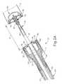
- An exemplary trans-oral circular anvil introduction system ( 200 )is shown in FIGS. 8-10 .
- Anvil introduction system ( 200 ) of the present examplecomprises a dilation feature, such as inflatable bladder ( 210 ), which is expandable around anvil ( 240 ) to cover any sharp edges of anvil ( 240 ) during the introduction of anvil ( 240 ) through a naturally occurring bodily lumen (e.g. the esophagus).
- anvil introduction system ( 200 )comprises an anvil ( 240 ), an inflatable bladder ( 210 ), and a flexible tube ( 222 ), as shown in FIG. 8 .
- Anvil ( 240 )is similar to anvil ( 40 ) described above.
- Anvil ( 240 )comprises staple pockets ( 252 ) aligned on proximal surface ( 250 ) of anvil ( 240 ).
- Anvil ( 240 )also comprises a proximally extending shaft ( 244 ).
- Shaft ( 244 )is coupled to inflatable bladder ( 210 ).
- Inflatable bladder ( 210 )comprises a flexible membrane that wraps around shaft ( 244 ) and inflates to cover staple pockets ( 252 ) and the edge of proximal surface ( 250 ) of anvil ( 240 ), as shown in FIG. 9B . In the inflated state, bladder ( 210 ) defines a tapered shape from anvil ( 240 ).
- Apertures ( 211 )are provided in shaft ( 244 ) to allow air, saline, or other fluid to pass through shaft ( 244 ) to inflate bladder ( 210 ).
- Tubular member ( 212 )extends from bladder ( 210 ) to selectively couple bladder ( 210 ) to flexible tube ( 222 ).
- Shaft ( 244 )is similar to proximal shaft ( 42 ) of anvil ( 40 ) such that shaft ( 244 ) is configured to couple with trocar ( 38 ) once anvil ( 240 ) is positioned for stapling.
- Flexible tube ( 222 )comprises a snap feature ( 220 ) and an inflation tube ( 224 ).
- Snap feature ( 220 )extends from the distal end of flexible tube ( 222 ).
- Snap feature ( 220 )comprises a smaller diameter than tubular member ( 212 ) such that snap feature ( 220 ) slides or snaps into tubular member ( 212 ) to couple flexible tube ( 222 ) to tubular member ( 212 ), as shown in FIG. 9A .
- Snap feature ( 220 )may also have a larger diameter than tubular member ( 212 ) such that snap feature ( 220 ) slides around tubular member ( 212 ). Snap feature ( 220 ) may also be sutured to tubular member ( 212 ).
- Inflation tube ( 224 )is positioned within flexible tube ( 222 ). Inflation tube may be used to inject fluid into bladder ( 210 ) to inflate bladder ( 210 ). However, inflation tube ( 224 ) is merely optional and flexible tube ( 222 ) may be used to inject fluid into bladder ( 210 ). Flexible tube ( 222 ) may comprise a conventional NG (naso-gastric) tube or any other suitable structure.
- snap feature ( 220 )is inserted into tubular member ( 212 ) to couple flexible tube ( 222 ) to tubular member ( 212 ).
- inflation tube ( 224 )introduces fluid into bladder ( 210 ) to inflate bladder ( 210 ), as shown in FIG. 9B .
- bladder ( 210 )With bladder ( 210 ) inflated, bladder ( 210 ) covers staple pockets ( 252 ).
- Bladder ( 210 )also extends past anvil ( 240 ) to form an annular protrusion ( 214 ) to cover the edge of proximal surface ( 250 ) of anvil ( 240 ).
- flexible tube ( 222 )is used to pull anvil ( 240 ) smoothly through a naturally occurring bodily lumen (e.g., the esophagus), as shown in FIG. 10 .
- bladder ( 210 )is deflated by passing the fluid back through inflation tube ( 224 ).
- Flexible tube ( 222 )is then be removed from anvil ( 240 ), and anvil ( 240 ) is coupled to trocar ( 38 ) of circular surgical stapling instrument ( 10 ) for operation.
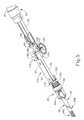
- Anvil introduction system ( 300 )comprises an anvil ( 340 ), a flexible tube ( 322 ), a sliding feature ( 360 ), and a dilation feature ( 361 ).
- Anvil ( 340 )is similar to anvil ( 40 ) described above.
- Anvil ( 340 )comprises staple pockets ( 352 ) aligned on proximal surface ( 350 ) of anvil ( 340 ), as shown in FIG. 15 .
- Anvil ( 340 )also comprises a shaft ( 344 ) extending from proximal surface ( 350 ) of anvil ( 340 ).
- Shaft ( 344 )is similar to proximal shaft ( 42 ) of anvil ( 40 ) such that shaft ( 344 ) is configured to couple with trocar ( 38 ) once anvil ( 340 ) is positioned for stapling.
- Shaft ( 344 )is coupled to flexible tube ( 322 ) as anvil ( 340 ) is being moved into a position for stapling.
- Shaft ( 344 )comprises a smaller diameter than flexible tube ( 322 ) such that shaft ( 344 ) slides into flexible tube ( 322 ) to couple flexible tube ( 322 ) to anvil ( 340 ).
- Shaft ( 344 )may also have a larger diameter than flexible tube ( 322 ) such that shaft ( 344 ) may slide around flexible tube ( 322 ). Shaft ( 344 ) may also be sutured to flexible tube ( 322 ) through corresponding apertures ( 312 , 320 ) in shaft ( 344 ) and flexible tube ( 322 ). Other suitable methods to couple flexible tube ( 322 ) to shaft ( 344 ) will be apparent to one with ordinary skill in the art based on the teachings herein.
- Flexible tube ( 322 )may comprise a conventional NG (naso-gastric) tube or any other suitable structure.
- Sliding feature ( 360 )is coupled to flexible tube ( 322 ).
- Sliding feature ( 360 )comprises a sliding collar ( 368 ), connecting members ( 367 ), and a cam collar ( 366 ), as shown in FIG. 11 .
- Sliding collar ( 368 )wraps around flexible tube ( 322 ) such that sliding collar ( 368 ) slides proximally and/or distally along flexible tube ( 322 ).
- a cam collar ( 366 )is positioned distal to sliding collar ( 368 ) and cam collar ( 366 ) also wraps around flexible tube ( 322 ) such that cam collar ( 366 ) slides proximally and/or distally along flexible tube ( 322 ).
- Cam collar ( 366 )defines a tapered configuration.
- One or more connecting members ( 367 )extend between sliding collar ( 368 ) and cam collar ( 366 ) to connect sliding collar ( 368 ) to cam collar ( 366 ).
- Dilation feature ( 361 )is also coupled to flexible tube ( 322 ), as shown in FIGS. 13-14 .
- Dilation feature ( 361 )comprises expanding members ( 362 ) and a washer ( 363 ).
- Washer ( 363 )wraps around flexible tube ( 322 ) such that washer ( 363 ) is positioned between cam collar ( 366 ) and sliding collar ( 368 ).
- Washer ( 363 )is fixed relative to flexible tube ( 322 ) such that sliding feature ( 360 ) also slides relative to washer ( 363 ).
- a plurality of expanding members ( 362 )extend distally from washer ( 363 ) to anvil ( 340 ).
- Expanding members ( 362 )are positioned to extend from underneath sliding collar ( 368 ) and over cam collar ( 366 ), as shown in FIG. 11 .
- a mesh ( 364 )is applied to dilation feature ( 361 ) to cover expanding members ( 362 ).
- Mesh ( 364 )is configured to taper from anvil ( 340 ) to washer ( 363 ).
- Mesh ( 364 )expands and contracts with expanding members ( 362 ).
- mesh ( 364 )extends up to the bottom of the head of anvil ( 340 ).
- mesh ( 364 )fully encompasses the head of anvil ( 340 ).
- mesh ( 364 )may fully encompass the shaft of anvil ( 340 ).
- flexible tube ( 322 )is coupled to anvil ( 340 ) via shaft ( 344 ), with dilation feature ( 361 ) in a collapsed state.
- Expanding members ( 362 ) and/or mesh ( 364 )may be resiliently biased to assume the collapsed configuration of FIGS. 15-16 .
- sliding feature ( 360 )is in a distal position such that cam collar ( 366 ) is distal to washer ( 363 ).
- a usergrasps sliding collar ( 368 ) to translate sliding feature ( 360 ) to a proximal position, as shown in FIGS. 13-14 .
- a conventional grasper or any other devicemay be used to translate sliding collar ( 368 ).
- cam collar ( 366 )also translates proximally to engage washer ( 363 ).
- the tapered configuration of cam collar ( 366 ) underneath expanding members ( 362 )acts as a cam, pushing expanding members ( 362 ) outwardly to an expanded state.
- expanding members ( 362 )contact the edge of proximal surface ( 350 ) of anvil ( 340 ).
- Mesh ( 364 )also expands with expanding members ( 362 ).
- dilation feature ( 361 )covers the edge and staple pockets ( 352 ) of anvil ( 340 ).
- anvil ( 340 )With proximal surface ( 350 ) of anvil ( 340 ) covered by dilation feature ( 361 ), anvil ( 340 ) is introduced trans-orally by pulling flexible tube ( 322 ) of anvil introduction system ( 300 ) through the esophagus, as shown in FIG. 17A .
- dilation feature ( 361 )When dilation feature ( 361 ) is in the expanded position, dilation feature ( 362 ) prevents the edge of anvil ( 340 ) from dragging along the inner wall of the esophagus.
- suture ( 380 ) connecting flexible tube ( 322 ) and anvil shaft ( 344 )is cut.
- Sliding collar ( 368 )is then advanced distally to allow dilation feature ( 361 ) to collapse.
- flexible tube ( 322 )is then pulled to remove flexible tube ( 322 ), sliding feature ( 360 ), and dilation feature ( 361 ) from anvil ( 340 ).
- Anvil ( 340 )is then coupled to trocar ( 38 ) of circular surgical stapling instrument ( 10 ) for operation.
- An anvil ( 40 )may comprise an anvil grasping features to facilitate pulling anvil ( 40 ) upside-down through the esophagus such that the proximal side of anvil ( 40 ) faces away from tissue. This may enable a tapered or curved upper surface of anvil ( 40 ) to engage tissue as anvil ( 40 ) is pulled through the esophagus.
- a flexible or rigid anvil grasping featuremay be used.
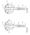
- FIGS. 18-19Cshow an exemplary anvil assembly ( 400 ) comprising an anvil grasping feature ( 448 ).
- Grasping feature ( 448 )is used to grasp anvil ( 440 ) at an orientation with top surface ( 442 ) leading through a naturally occurring bodily lumen (e.g. the esophagus).
- Anvil assembly ( 400 )comprises an anvil ( 440 ), an anvil grasping feature ( 448 ), and an anvil shaft ( 444 ), as shown in FIG. 18 .
- Anvil ( 440 )is similar to anvil ( 40 ) described above.
- Anvil ( 440 )comprises staple pockets ( 452 ) on lower surface ( 450 ) of anvil ( 440 ).
- Shaft ( 444 )extends from lower surface ( 450 ) of anvil ( 440 ). Shaft ( 444 ) is coupleable to trocar ( 38 ).
- Anvil ( 440 )defines a tapered configuration such that top surface ( 442 ) comprises a smaller diameter than lower surface ( 450 ).
- Grasping feature ( 448 )extends from top surface ( 442 ) of anvil ( 440 ). Grasping feature ( 448 ) may be flexible. As shown in FIG. 18 , grasping feature ( 448 ) is configured as a rounded tab. Grasping feature ( 448 ) may also be configured as a long, round cylindrical tab, or a flat fin shaped tab. Other suitable grasping configurations will be apparent to one with ordinary skill in the art in view of the teachings herein.
- anvil ( 440 )is introduced by leading top surface ( 442 ) trans-orally through the esophagus.
- the tapered configuration defined by anvil ( 440 )provides a smooth transit for anvil ( 440 ) through the esophagus.
- a suture ( 450 )is coupled around shaft ( 444 ) of anvil ( 440 ).
- a conventional surgical grasper ( 460 )is used to grab grasping feature ( 448 ) with grasping end effector jaws ( 462 ), as shown in FIG. 19A .
- Grasper ( 460 )is then pulled through the esophagus to trans-orally introduce anvil ( 440 ) to the intended anastomosis site.
- grasper ( 460 )releases grasping feature ( 448 ).
- grasper ( 460 )then grabs suture ( 450 ) to pull anvil shaft ( 444 ) to thereby flip anvil ( 440 ) to align lower surface ( 450 ) with the desired tissue ( 2 ) to be stapled.
- grasper ( 460 )continues to pull anvil ( 440 ) into position, as shown in FIG. 19C .
- Suture ( 350 )is then cut and grasper ( 460 ) is removed.
- Anvil ( 440 )is then coupled to trocar ( 38 ) of circular surgical stapling instrument ( 10 ) for operation.
- FIGS. 20-21Bshow another exemplary anvil assembly ( 700 ) comprising an anvil grasping feature ( 748 ).
- Anvil assembly ( 700 )comprises an anvil ( 740 ) and an anvil grasping feature ( 748 ), as shown in FIG. 20 .
- Anvil ( 740 )is similar to anvil ( 40 ) described above.
- Anvil ( 740 )comprises staple pockets ( 752 ) on lower surface ( 750 ) of anvil ( 740 ).
- a shaft ( 746 )extends from top surface ( 742 ) of anvil ( 740 ) to connect anvil grasping feature ( 748 ) to anvil ( 740 ).
- Anvil grasping feature ( 748 )comprises a convex shaped top.
- Opening ( 744 )is formed on lower surface ( 750 ) of anvil ( 740 ) to receive trocar ( 738 ), as shown in FIG. 21A .
- Opening ( 744 )comprises an inwardly extending annular protrusion ( 743 ).
- Trocar ( 738 )is similar to trocar ( 38 ).
- Trocar ( 738 )comprises a pointed distal end ( 730 ), a cam portion ( 732 ), a shaft ( 733 ), and expanding members ( 736 ), as shown in FIG. 21A .
- the distal portion of shaft ( 733 )is angled to form cam portion ( 732 ).
- Pointed distal end ( 730 )is positioned distal to cam portion ( 732 ).
- Shaft ( 733 )extends through expanding members ( 736 ).
- Expanding members ( 736 )comprise inwardly extending recesses ( 734 ) that correspond to protrusion ( 743 ).
- anvil ( 740 )is introduced by leading top surface ( 742 ) through a naturally occurring bodily lumen (e.g. the esophagus).
- a grasperis used to grab grasping feature ( 748 ) with jaws to pull anvil ( 740 ) trans-orally through the esophagus.
- Anvil ( 740 )is flipped to align lower surface ( 750 ) with tissue ( 2 ) to be stapled. Once anvil ( 740 ) is positioned within the esophagus, anvil ( 740 ) is coupled to trocar ( 738 ) for operation.
- trocar ( 738 )is inserted into opening ( 744 ) of anvil ( 740 ) until recesses ( 734 ) align with protrusion ( 743 ), as shown in FIG. 21A .
- Shaft ( 733 )is pulled proximally to slide shaft ( 733 ) through expanding members ( 736 ).
- cam portion ( 732 )pushes expanding members ( 736 ) outwardly, as shown in FIG. 21B . This causes recesses ( 734 ) to engage protrusion ( 743 ).
- shaft ( 733 )The longitudinal position of shaft ( 733 ) relative to expanding members ( 736 ) is secured in order to cause recesses ( 734 ) of trocar ( 738 ) to lock anvil ( 740 ) to trocar ( 738 ) during operation of circular surgical stapling instrument ( 10 ).
- shaft ( 733 )may be translated distally to allow expanding members ( 736 ) to bend inwardly. This removes recesses ( 734 ) from protrusion ( 743 ) to unlock anvil ( 740 ) from trocar ( 738 ).
- Instrument ( 10 ) and anvil ( 740 )may then be removed separately from the anastomosis site. Alternatively, instrument ( 10 ) may be removed from the anastomosis site with anvil ( 740 ) still coupled to trocar ( 738 ).
- An anvil securing feature ( 848 )may be applied to the various anvils, including those described above, to hold anvil ( 840 ) in place relative to tissue while coupling anvil ( 840 ) to a trocar ( 38 ).
- An exemplary anvil assembly ( 800 ) comprising an anvil securing feature ( 848 )is shown in FIGS. 22A-22B .
- Anvil assembly ( 800 )comprises an anvil ( 840 ) and an anvil securing feature ( 848 ).
- Anvil ( 840 )is similar to anvil ( 40 ) described above.
- Anvil ( 840 )comprises staple pockets ( 852 ) on lower surface ( 850 ) of anvil ( 840 ).
- a shaft ( 844 )extends from lower surface ( 850 ) of anvil ( 840 ).
- Anvil securing feature ( 848 )is fixedly coupled to shaft ( 844 ).
- Anvil securing feature ( 848 )comprises a collar ( 822 ) and a flange ( 820 ) extending from collar ( 822 ), as shown in FIG. 22A .
- Collar ( 822 )is configured to wrap around shaft ( 844 ) to couple anvil securing feature ( 848 ) to anvil ( 840 ).
- An opening ( 824 )is formed in flange ( 820 ) such that a suture may pass through opening ( 824 ).
- flange ( 820 )may be formed of a compliant material to enable needle ( 832 ) to pierce flange ( 820 ) at any desired location on flange ( 820 ).
- anvil securing feature ( 848 )allows for retention of anvil ( 840 ) relative to tissue after a grasper is removed from anvil ( 840 ).
- tissue ( 2 )is sutured in a purse-string configuration.
- Suture ( 830 )then passes through opening ( 824 ) of anvil securing feature ( 848 ) by needle ( 832 ).
- a loopis formed through opening ( 824 ) around flange ( 820 ) with suture ( 830 ).
- anvil ( 840 )is held in position by suture ( 830 ). With anvil ( 840 ) secured to tissue ( 2 ), anvil ( 840 ) is held in place when anvil ( 840 ) is coupled to a trocar ( 38 ).
- Other suitable suturing methods to retain anvil ( 840 )will be apparent to one with ordinary skill in the art in view of the teachings herein.
- Versions of the devices described abovemay have application in conventional medical treatments and procedures conducted by a medical professional, as well as application in robotic-assisted medical treatments and procedures.
- various teachings hereinmay be readily incorporated into a robotic surgical system such as the DAVINCITM system by Intuitive Surgical, Inc., of Sunnyvale, Calif.
- DAVINCITM systemby Intuitive Surgical, Inc., of Sunnyvale, Calif.
- teachings hereinmay be readily combined with various teachings of U.S. Pat. No. 6,783,524, entitled “Robotic Surgical Tool with Ultrasound Cauterizing and Cutting Instrument,” published Aug. 31, 2004, the disclosure of which is incorporated by reference herein.
- Versions described abovemay be designed to be disposed of after a single use, or they can be designed to be used multiple times. Versions may, in either or both cases, be reconditioned for reuse after at least one use. Reconditioning may include any combination of the steps of disassembly of the device, followed by cleaning or replacement of particular pieces, and subsequent reassembly. In particular, some versions of the device may be disassembled, and any number of the particular pieces or parts of the device may be selectively replaced or removed in any combination. Upon cleaning and/or replacement of particular parts, some versions of the device may be reassembled for subsequent use either at a reconditioning facility, or by a user immediately prior to a procedure.
- reconditioning of a devicemay utilize a variety of techniques for disassembly, cleaning/replacement, and reassembly. Use of such techniques, and the resulting reconditioned device, are all within the scope of the present application.
- versions described hereinmay be sterilized before and/or after a procedure.
- the deviceis placed in a closed and sealed container, such as a plastic or TYVEK bag.
- the container and devicemay then be placed in a field of radiation that can penetrate the container, such as gamma radiation, x-rays, or high-energy electrons.
- the radiationmay kill bacteria on the device and in the container.
- the sterilized devicemay then be stored in the sterile container for later use.
- a devicemay also be sterilized using any other technique known in the art, including but not limited to beta or gamma radiation, ethylene oxide, or steam.
Landscapes
- Health & Medical Sciences (AREA)
- Life Sciences & Earth Sciences (AREA)
- Surgery (AREA)
- Heart & Thoracic Surgery (AREA)
- Engineering & Computer Science (AREA)
- Biomedical Technology (AREA)
- Nuclear Medicine, Radiotherapy & Molecular Imaging (AREA)
- Medical Informatics (AREA)
- Molecular Biology (AREA)
- Animal Behavior & Ethology (AREA)
- General Health & Medical Sciences (AREA)
- Public Health (AREA)
- Veterinary Medicine (AREA)
- Physiology (AREA)
- Surgical Instruments (AREA)
Abstract
Description
Claims (17)
Priority Applications (10)
| Application Number | Priority Date | Filing Date | Title |
|---|---|---|---|
| US13/693,430US9572573B2 (en) | 2012-12-04 | 2012-12-04 | Trans-oral circular anvil introduction system with dilation feature |
| RU2015126850ARU2655117C2 (en) | 2012-12-04 | 2013-12-04 | Trans-oral circular anvil introduction system with dilation feature |
| EP13821008.3AEP2928387B1 (en) | 2012-12-04 | 2013-12-04 | Trans-oral circular anvil introduction system with dilation feature |
| CN201380063907.6ACN104837415B (en) | 2012-12-04 | 2013-12-04 | Oral circular anvil with enlarging property structure introduces system |
| IN3982DEN2015IN2015DN03982A (en) | 2012-12-04 | 2013-12-04 | |
| PCT/US2013/073097WO2014089197A1 (en) | 2012-12-04 | 2013-12-04 | Trans-oral circular anvil introduction system with dilation feature |
| BR112015013062-3ABR112015013062B1 (en) | 2012-12-04 | 2013-12-04 | APPLIANCE FOR FABRIC STAPLING |
| JP2015545817AJP6373859B2 (en) | 2012-12-04 | 2013-12-04 | Oral circular anvil introduction system with expanded features |
| MX2015007040AMX357428B (en) | 2012-12-04 | 2013-12-04 | Trans-oral circular anvil introduction system with dilation feature. |
| US15/214,839US10743866B2 (en) | 2012-12-04 | 2016-07-20 | Trans-oral circular anvil introduction system with dilation feature |
Applications Claiming Priority (1)
| Application Number | Priority Date | Filing Date | Title |
|---|---|---|---|
| US13/693,430US9572573B2 (en) | 2012-12-04 | 2012-12-04 | Trans-oral circular anvil introduction system with dilation feature |
Related Child Applications (1)
| Application Number | Title | Priority Date | Filing Date |
|---|---|---|---|
| US15/214,839ContinuationUS10743866B2 (en) | 2012-12-04 | 2016-07-20 | Trans-oral circular anvil introduction system with dilation feature |
Publications (2)
| Publication Number | Publication Date |
|---|---|
| US20140151429A1 US20140151429A1 (en) | 2014-06-05 |
| US9572573B2true US9572573B2 (en) | 2017-02-21 |
Family
ID=49955476
Family Applications (2)
| Application Number | Title | Priority Date | Filing Date |
|---|---|---|---|
| US13/693,430Active2034-12-05US9572573B2 (en) | 2012-12-04 | 2012-12-04 | Trans-oral circular anvil introduction system with dilation feature |
| US15/214,839Active2034-09-08US10743866B2 (en) | 2012-12-04 | 2016-07-20 | Trans-oral circular anvil introduction system with dilation feature |
Family Applications After (1)
| Application Number | Title | Priority Date | Filing Date |
|---|---|---|---|
| US15/214,839Active2034-09-08US10743866B2 (en) | 2012-12-04 | 2016-07-20 | Trans-oral circular anvil introduction system with dilation feature |
Country Status (9)
| Country | Link |
|---|---|
| US (2) | US9572573B2 (en) |
| EP (1) | EP2928387B1 (en) |
| JP (1) | JP6373859B2 (en) |
| CN (1) | CN104837415B (en) |
| BR (1) | BR112015013062B1 (en) |
| IN (1) | IN2015DN03982A (en) |
| MX (1) | MX357428B (en) |
| RU (1) | RU2655117C2 (en) |
| WO (1) | WO2014089197A1 (en) |
Cited By (41)
| Publication number | Priority date | Publication date | Assignee | Title |
|---|---|---|---|---|
| US20160324525A1 (en)* | 2012-12-04 | 2016-11-10 | Ethicon Endo-Surgery, Llc | Trans-oral circular anvil introduction system with dilation feature |
| US10188386B2 (en) | 2015-06-26 | 2019-01-29 | Ethicon Llc | Surgical stapler with anvil state indicator |
| US10271851B2 (en) | 2016-04-01 | 2019-04-30 | Ethicon Llc | Modular surgical stapling system comprising a display |
| US10285705B2 (en) | 2016-04-01 | 2019-05-14 | Ethicon Llc | Surgical stapling system comprising a grooved forming pocket |
| US10307159B2 (en) | 2016-04-01 | 2019-06-04 | Ethicon Llc | Surgical instrument handle assembly with reconfigurable grip portion |
| US10512467B2 (en) | 2012-12-17 | 2019-12-24 | Ethicon Llc | Motor driven rotary input circular stapler with modular end effector |
| US10517602B2 (en) | 2015-06-26 | 2019-12-31 | Ethicon Llc | Surgical stapler with reversible polarity |
| US10542981B2 (en) | 2016-11-14 | 2020-01-28 | Ethicon Llc | Atraumatic stapling head features for circular surgical stapler |
| US10588612B2 (en) | 2011-03-14 | 2020-03-17 | Ethicon Llc | Collapsible anvil plate assemblies for circular surgical stapling devices |
| US10603041B2 (en) | 2016-11-14 | 2020-03-31 | Ethicon Llc | Circular surgical stapler with angularly asymmetric deck features |
| EP3639762A2 (en) | 2018-10-15 | 2020-04-22 | Ethicon LLC | Dual lever to reduce force to fire in circular surgical stapler |
| US10675035B2 (en) | 2010-09-09 | 2020-06-09 | Ethicon Llc | Surgical stapling head assembly with firing lockout for a surgical stapler |
| US10695068B2 (en) | 2017-04-28 | 2020-06-30 | Ethicon Llc | Hysteresis removal feature in surgical stapling instrument |
| US10709452B2 (en) | 2013-09-23 | 2020-07-14 | Ethicon Llc | Methods and systems for performing circular stapling |
| US10729444B2 (en) | 2017-04-28 | 2020-08-04 | Ethicon Llc | Liquid-immune trigger circuit for surgical instrument |
| USD893719S1 (en)* | 2018-05-16 | 2020-08-18 | Ethicon Llc | Surgical stapler |
| USD893721S1 (en)* | 2018-05-16 | 2020-08-18 | Ethicon Llc | Surgical stapler |
| USD893720S1 (en)* | 2018-05-16 | 2020-08-18 | Ethicon Llc | Surgical stapler |
| USD893718S1 (en)* | 2018-05-16 | 2020-08-18 | Ethicon Llc | Surgical stapler |
| US10751059B2 (en) | 2017-09-27 | 2020-08-25 | Ethicon Llc | Circular stapling instrument anvil with shank having unitary latches with living hinge |
| US10758236B2 (en) | 2017-09-27 | 2020-09-01 | Ethicon Llc | Circular stapling instrument with torque limiting feature |
| EP3705059A2 (en) | 2019-03-08 | 2020-09-09 | Ethicon LLC | Circular surgical stapler |
| EP3705061A2 (en) | 2019-03-08 | 2020-09-09 | Ethicon LLC | Staple height indicator for powered surgical stapler |
| USD896962S1 (en)* | 2018-05-16 | 2020-09-22 | Ethicon Llc | Surgical stapler |
| US10786249B2 (en) | 2013-09-23 | 2020-09-29 | Ethicon Llc | Surgical stapler with rotary cam drive |
| US10835256B2 (en) | 2017-09-27 | 2020-11-17 | Ethicon Llc | Circular stapling instrument with firing trigger having integral resilient features |
| US10835254B2 (en) | 2012-12-17 | 2020-11-17 | Ethicon Llc | Powered surgical circular stapler |
| USD905242S1 (en)* | 2018-05-16 | 2020-12-15 | Ethicon Llc | Surgical stapler |
| US10959724B2 (en) | 2013-09-23 | 2021-03-30 | Ethicon Llc | Surgical stapler with rotary cam drive and return |
| US10980542B2 (en) | 2016-11-14 | 2021-04-20 | Ethicon Llc | Circular surgical stapler with recessed deck |
| US11039839B2 (en) | 2017-09-27 | 2021-06-22 | Cilag Gmbh International | Circular stapling instrument with unitary closure rod |
| US11051819B2 (en) | 2018-10-15 | 2021-07-06 | Cilag Gmbh International | Latch to prevent back-driving of circular surgical stapler |
| US11058428B2 (en) | 2017-09-27 | 2021-07-13 | Cilag Gmbh International | Circular stapling instrument with asymmetric molded shroud components |
| US11116508B2 (en) | 2019-03-08 | 2021-09-14 | Cilag Gmbh International | Electrical potential shifting circuit for powered surgical stapler |
| US11185324B2 (en) | 2019-09-18 | 2021-11-30 | Cilag Gmbh International | Anvil retention and release features for powered circular surgical stapler |
| US11207071B2 (en) | 2018-10-15 | 2021-12-28 | Cilag Gmbh International | Dual stage closure system for circular surgical stapler |
| US11224432B2 (en) | 2019-03-08 | 2022-01-18 | Cilag Gmbh International | Timer circuit to control firing of powered surgical stapler |
| US11284890B2 (en) | 2016-04-01 | 2022-03-29 | Cilag Gmbh International | Circular stapling system comprising an incisable tissue support |
| US11701109B2 (en) | 2018-12-28 | 2023-07-18 | Cilag Gmbh International | Surgical stapler with sloped staple deck for varying tissue compression |
| US12082817B2 (en) | 2019-03-08 | 2024-09-10 | Cilag Gmbh International | Power control circuit for powered surgical stapler |
| US12419637B2 (en) | 2016-04-01 | 2025-09-23 | Cilag Gmbh International | Surgical stapling instrument |
Families Citing this family (33)
| Publication number | Priority date | Publication date | Assignee | Title |
|---|---|---|---|---|
| US7938307B2 (en)* | 2004-10-18 | 2011-05-10 | Tyco Healthcare Group Lp | Support structures and methods of using the same |
| US20180132849A1 (en) | 2016-11-14 | 2018-05-17 | Ethicon Endo-Surgery, Llc | Staple forming pocket configurations for circular surgical stapler anvil |
| US10478189B2 (en) | 2015-06-26 | 2019-11-19 | Ethicon Llc | Method of applying an annular array of staples to tissue |
| US9987001B2 (en) | 2015-06-12 | 2018-06-05 | Covidien Lp | Surgical anastomosis apparatus |
| US10905415B2 (en) | 2015-06-26 | 2021-02-02 | Ethicon Llc | Surgical stapler with electromechanical lockout |
| US10307157B2 (en) | 2015-06-26 | 2019-06-04 | Ethicon Llc | Surgical stapler with anvil seating detection |
| US10271842B2 (en) | 2015-06-26 | 2019-04-30 | Ethicon Llc | Anvil stabilization features for surgical stapler |
| US10265066B2 (en) | 2015-06-26 | 2019-04-23 | Ethicon Llc | Surgical stapler with incomplete firing indicator |
| US10456134B2 (en) | 2015-06-26 | 2019-10-29 | Ethicon Llc | Surgical stapler with reversible motor |
| US10194911B2 (en) | 2015-06-26 | 2019-02-05 | Ethicon Llc | Surgical stapler with ready state indicator |
| US10226253B2 (en) | 2015-06-26 | 2019-03-12 | Ethicon Llc | Firing assembly for circular stapler |
| US10271841B2 (en) | 2015-06-26 | 2019-04-30 | Ethicon Llc | Bailout assembly for surgical stapler |
| US10405855B2 (en) | 2015-06-26 | 2019-09-10 | Ethicon Llc | Firing circuit for surgical stapler |
| US10492790B2 (en) | 2015-09-24 | 2019-12-03 | Ethicon Llc | Apparatus and method for cinching a straight staple line |
| US10485548B2 (en) | 2015-09-24 | 2019-11-26 | Ethicon Llc | Apparatus and method for forming a staple line with trocar passageway |
| US10499909B2 (en) | 2015-09-24 | 2019-12-10 | Ethicon Llc | Apparatus and method for pleating a bodily lumen |
| US9987013B2 (en) | 2015-09-24 | 2018-06-05 | Ethicon Llc | Surgical staple buttress with magnetic elements |
| US10307165B2 (en) | 2015-09-24 | 2019-06-04 | Ethicon Llc | Apparatus and method for radially bunching a bodily lumen |
| US10542992B2 (en)* | 2015-10-19 | 2020-01-28 | Covidien Lp | Loading unit with stretchable bushing |
| CN109310432B (en)* | 2016-04-01 | 2021-08-24 | 伊西康有限责任公司 | Surgical stapling system including jaw attachment lockout |
| GB201611306D0 (en) | 2016-06-29 | 2016-08-10 | Norwegian Univ Of Science And Tech (Ntnu) | Surgical stapler and a method of stapling tissue |
| US10925607B2 (en)* | 2017-02-28 | 2021-02-23 | Covidien Lp | Surgical stapling apparatus with staple sheath |
| WO2019091343A1 (en)* | 2017-11-10 | 2019-05-16 | Ethicon Llc | Laparoscopic stapler with flippable staple housing assembly and flippable anvil assembly |
| CN108186068A (en)* | 2017-12-20 | 2018-06-22 | 西人马(厦门)科技有限公司 | The intelligent stapler of body temperature can be perceived |
| CN108186069A (en)* | 2017-12-20 | 2018-06-22 | 西人马(厦门)科技有限公司 | Plug-in conducting connecting part and visual intelligent stapler |
| US20190201034A1 (en)* | 2017-12-28 | 2019-07-04 | Ethicon Llc | Powered stapling device configured to adjust force, advancement speed, and overall stroke of cutting member based on sensed parameter of firing or clamping |
| CN108175465A (en)* | 2018-01-10 | 2018-06-19 | 苏州贝诺医疗器械有限公司 | A kind of tube type anastomat |
| EP3563778A3 (en) | 2018-03-07 | 2019-12-18 | Ethicon LLC | Surgical stapler with reversible polarity |
| US10595873B2 (en)* | 2018-04-19 | 2020-03-24 | Franklin Institute of Innovation, LLC | Surgical staplers and related methods |
| US20210219978A1 (en)* | 2018-05-10 | 2021-07-22 | Franklin Institute of Innovation, LLC | Surgical staplers and related methods |
| US11504127B2 (en)* | 2019-01-08 | 2022-11-22 | Olympus Corporation | Method for anastomosing alimentary tract |
| RU2740427C1 (en)* | 2020-04-03 | 2021-01-14 | Артем Александрович Махалов | Method for extraperitoneal ligation of vaginal process of peritoneum under ultrasound control in congenital inguinal hernias, hydrocele and spermatic cord hydrocyst in children and instrument for implementation thereof |
| US20240225652A1 (en)* | 2021-06-09 | 2024-07-11 | Covidien Lp | Retractable trocar for circular stapling instruments |
Citations (29)
| Publication number | Priority date | Publication date | Assignee | Title |
|---|---|---|---|---|
| GB2038692A (en) | 1978-12-07 | 1980-07-30 | United States Surgical Corp | Precisely aligned anastomosis stapling cartridge and instrument |
| DE8714082U1 (en) | 1987-04-21 | 1988-02-18 | United States Surgical Corp., Norwalk, Conn. | Mushroom-shaped anvil for a surgical stapler |
| US4805823A (en) | 1988-03-18 | 1989-02-21 | Ethicon, Inc. | Pocket configuration for internal organ staplers |
| US4817847A (en) | 1986-04-21 | 1989-04-04 | Finanzaktiengesellschaft Globe Control | Instrument and a procedure for performing an anastomosis |
| US4873977A (en)* | 1987-02-11 | 1989-10-17 | Odis L. Avant | Stapling method and apparatus for vesicle-urethral re-anastomosis following retropubic prostatectomy and other tubular anastomosis |
| US5205459A (en) | 1991-08-23 | 1993-04-27 | Ethicon, Inc. | Surgical anastomosis stapling instrument |
| US5333773A (en) | 1991-08-23 | 1994-08-02 | Ethicon, Inc. | Sealing means for endoscopic surgical anastomosis stapling instrument |
| US5350104A (en) | 1991-08-23 | 1994-09-27 | Ethicon, Inc. | Sealing means for endoscopic surgical anastomosis stapling instrument |
| US5415334A (en) | 1993-05-05 | 1995-05-16 | Ethicon Endo-Surgery | Surgical stapler and staple cartridge |
| US5465895A (en) | 1994-02-03 | 1995-11-14 | Ethicon Endo-Surgery, Inc. | Surgical stapler instrument |
| US5597107A (en) | 1994-02-03 | 1997-01-28 | Ethicon Endo-Surgery, Inc. | Surgical stapler instrument |
| US5632432A (en) | 1994-12-19 | 1997-05-27 | Ethicon Endo-Surgery, Inc. | Surgical instrument |
| US5704534A (en) | 1994-12-19 | 1998-01-06 | Ethicon Endo-Surgery, Inc. | Articulation assembly for surgical instruments |
| US5814055A (en) | 1995-09-19 | 1998-09-29 | Ethicon Endo-Surgery, Inc. | Surgical clamping mechanism |
| WO2001066020A2 (en) | 2000-03-06 | 2001-09-13 | United States Surgical | Apparatus and method for performing a bypass procedure in a digestive system |
| US20030014064A1 (en)* | 1999-04-16 | 2003-01-16 | Blatter Duane D. | Anvil apparatus for anastomosis and related methods and systems |
| US6783524B2 (en) | 2001-04-19 | 2004-08-31 | Intuitive Surgical, Inc. | Robotic surgical tool with ultrasound cauterizing and cutting instrument |
| US6978921B2 (en) | 2003-05-20 | 2005-12-27 | Ethicon Endo-Surgery, Inc. | Surgical stapling instrument incorporating an E-beam firing mechanism |
| US20060201989A1 (en)* | 2005-03-11 | 2006-09-14 | Ojeda Herminio F | Surgical anvil and system for deploying the same |
| US7143923B2 (en) | 2003-05-20 | 2006-12-05 | Ethicon Endo-Surgery, Inc. | Surgical stapling instrument having a firing lockout for an unclosed anvil |
| US7303108B2 (en) | 2003-09-29 | 2007-12-04 | Ethicon Endo-Surgery, Inc. | Surgical stapling instrument incorporating a multi-stroke firing mechanism with a flexible rack |
| US7367485B2 (en) | 2004-06-30 | 2008-05-06 | Ethicon Endo-Surgery, Inc. | Surgical stapling instrument incorporating a multistroke firing mechanism having a rotary transmission |
| US7380695B2 (en) | 2003-05-20 | 2008-06-03 | Ethicon Endo-Surgery, Inc. | Surgical stapling instrument having a single lockout mechanism for prevention of firing |
| US7380696B2 (en) | 2003-05-20 | 2008-06-03 | Ethicon Endo-Surgery, Inc. | Articulating surgical stapling instrument incorporating a two-piece E-beam firing mechanism |
| WO2008089404A2 (en) | 2007-01-19 | 2008-07-24 | Synovis Life Technologies, Inc. | Circular stapler anvil introducer |
| US7404508B2 (en) | 2005-07-26 | 2008-07-29 | Ethicon Endo-Surgery, Inc. | Surgical stapling and cutting device |
| US7434715B2 (en) | 2003-09-29 | 2008-10-14 | Ethicon Endo-Surgery, Inc. | Surgical stapling instrument having multistroke firing with opening lockout |
| US7721930B2 (en) | 2006-11-10 | 2010-05-25 | Thicon Endo-Surgery, Inc. | Disposable cartridge with adhesive for use with a stapling device |
| US20110257667A1 (en)* | 2010-04-15 | 2011-10-20 | Fujifilm Corporation | Anastomotic instrument, endoscope system, and control method of anastomotic instrument |
Family Cites Families (18)
| Publication number | Priority date | Publication date | Assignee | Title |
|---|---|---|---|---|
| SU1235495A1 (en)* | 1980-12-29 | 1986-06-07 | Всесоюзный научно-исследовательский и испытательный институт медицинской техники | Apparatus for placing compression anastomoses |
| US5285944A (en)* | 1987-05-26 | 1994-02-15 | United States Surgical Corporation | Surgical stapler apparatus |
| US5314435A (en)* | 1992-05-19 | 1994-05-24 | United States Surgical Corporation | Anvil delivery system |
| US5360154A (en)* | 1992-07-17 | 1994-11-01 | United States Surgical Corporation | Apparatus for creating partial anastomoses |
| US5836503A (en)* | 1996-04-22 | 1998-11-17 | United States Surgical Corporation | Insertion device for surgical apparatus |
| JPH114832A (en) | 1997-06-18 | 1999-01-12 | Nissho Corp | Auxiliary tool of automatic digestive tract anastomosing device |
| US7309341B2 (en)* | 2003-09-30 | 2007-12-18 | Ethicon Endo-Surgery, Inc. | Single lumen anastomosis applier for self-deploying fastener |
| EP1588667A1 (en)* | 2004-04-20 | 2005-10-26 | Polyganics B.V. | Devices for anastomosis |
| US7845536B2 (en) | 2004-10-18 | 2010-12-07 | Tyco Healthcare Group Lp | Annular adhesive structure |
| US7922743B2 (en) | 2004-10-18 | 2011-04-12 | Tyco Healthcare Group Lp | Structure for applying sprayable wound treatment material |
| EP1906844A1 (en)* | 2005-07-25 | 2008-04-09 | Endogun Medical Systems Ltd. | Anastomosis device and system |
| US9597080B2 (en)* | 2007-09-24 | 2017-03-21 | Covidien Lp | Insertion shroud for surgical instrument |
| US8770460B2 (en)* | 2008-12-23 | 2014-07-08 | George E. Belzer | Shield for surgical stapler and method of use |
| US20110114697A1 (en)* | 2009-11-19 | 2011-05-19 | Ethicon Endo-Surgery, Inc. | Circular stapler introducer with multi-lumen sheath |
| US9572573B2 (en)* | 2012-12-04 | 2017-02-21 | Ethicon Endo-Surgery, Llc | Trans-oral circular anvil introduction system with dilation feature |
| US9522002B2 (en)* | 2012-12-13 | 2016-12-20 | Covidien Lp | Surgical instrument with pressure distribution device |
| US10172622B2 (en)* | 2015-05-01 | 2019-01-08 | Jill Kelley | Applicator instrument with folding stapling tip |
| US9717515B1 (en)* | 2015-08-10 | 2017-08-01 | MW Support Services, LLC | Medical device for sleeve gastrectomy surgery |
- 2012
- 2012-12-04USUS13/693,430patent/US9572573B2/enactiveActive
- 2013
- 2013-12-04CNCN201380063907.6Apatent/CN104837415B/ennot_activeExpired - Fee Related
- 2013-12-04MXMX2015007040Apatent/MX357428B/enactiveIP Right Grant
- 2013-12-04EPEP13821008.3Apatent/EP2928387B1/ennot_activeNot-in-force
- 2013-12-04JPJP2015545817Apatent/JP6373859B2/ennot_activeExpired - Fee Related
- 2013-12-04ININ3982DEN2015patent/IN2015DN03982A/enunknown
- 2013-12-04WOPCT/US2013/073097patent/WO2014089197A1/enactiveApplication Filing
- 2013-12-04BRBR112015013062-3Apatent/BR112015013062B1/ennot_activeIP Right Cessation
- 2013-12-04RURU2015126850Apatent/RU2655117C2/ennot_activeIP Right Cessation
- 2016
- 2016-07-20USUS15/214,839patent/US10743866B2/enactiveActive
Patent Citations (37)
| Publication number | Priority date | Publication date | Assignee | Title |
|---|---|---|---|---|
| GB2038692A (en) | 1978-12-07 | 1980-07-30 | United States Surgical Corp | Precisely aligned anastomosis stapling cartridge and instrument |
| US4817847A (en) | 1986-04-21 | 1989-04-04 | Finanzaktiengesellschaft Globe Control | Instrument and a procedure for performing an anastomosis |
| US4873977A (en)* | 1987-02-11 | 1989-10-17 | Odis L. Avant | Stapling method and apparatus for vesicle-urethral re-anastomosis following retropubic prostatectomy and other tubular anastomosis |
| DE8714082U1 (en) | 1987-04-21 | 1988-02-18 | United States Surgical Corp., Norwalk, Conn. | Mushroom-shaped anvil for a surgical stapler |
| US4805823A (en) | 1988-03-18 | 1989-02-21 | Ethicon, Inc. | Pocket configuration for internal organ staplers |
| US5285945A (en) | 1991-08-23 | 1994-02-15 | Ethicon, Inc. | Surgical anastomosis stapling instrument |
| US5271544A (en) | 1991-08-23 | 1993-12-21 | Ethicon, Inc. | Surgical anastomosis stapling instrument |
| US5275322A (en) | 1991-08-23 | 1994-01-04 | Ethicon, Inc. | Surgical anastomosis stapling instrument |
| US5205459A (en) | 1991-08-23 | 1993-04-27 | Ethicon, Inc. | Surgical anastomosis stapling instrument |
| US5292053A (en) | 1991-08-23 | 1994-03-08 | Ethicon, Inc. | Surgical anastomosis stapling instrument |
| US5333773A (en) | 1991-08-23 | 1994-08-02 | Ethicon, Inc. | Sealing means for endoscopic surgical anastomosis stapling instrument |
| US5350104A (en) | 1991-08-23 | 1994-09-27 | Ethicon, Inc. | Sealing means for endoscopic surgical anastomosis stapling instrument |
| US5533661A (en) | 1991-08-23 | 1996-07-09 | Ethicon, Inc. | Sealing means for endoscopic surgical anastomosis stapling instrument |
| US5415334A (en) | 1993-05-05 | 1995-05-16 | Ethicon Endo-Surgery | Surgical stapler and staple cartridge |
| US5465895A (en) | 1994-02-03 | 1995-11-14 | Ethicon Endo-Surgery, Inc. | Surgical stapler instrument |
| US5597107A (en) | 1994-02-03 | 1997-01-28 | Ethicon Endo-Surgery, Inc. | Surgical stapler instrument |
| US5704534A (en) | 1994-12-19 | 1998-01-06 | Ethicon Endo-Surgery, Inc. | Articulation assembly for surgical instruments |
| US5632432A (en) | 1994-12-19 | 1997-05-27 | Ethicon Endo-Surgery, Inc. | Surgical instrument |
| US5673840A (en) | 1994-12-19 | 1997-10-07 | Ethicon Endo-Surgery, Inc. | Surgical instrument |
| US5814055A (en) | 1995-09-19 | 1998-09-29 | Ethicon Endo-Surgery, Inc. | Surgical clamping mechanism |
| US20030014064A1 (en)* | 1999-04-16 | 2003-01-16 | Blatter Duane D. | Anvil apparatus for anastomosis and related methods and systems |
| US7179267B2 (en)* | 2000-03-06 | 2007-02-20 | Tyco Healthcare Group Lp | Apparatus and method for performing a bypass procedure in a digestive system |
| WO2001066020A2 (en) | 2000-03-06 | 2001-09-13 | United States Surgical | Apparatus and method for performing a bypass procedure in a digestive system |
| US6783524B2 (en) | 2001-04-19 | 2004-08-31 | Intuitive Surgical, Inc. | Robotic surgical tool with ultrasound cauterizing and cutting instrument |
| US7380695B2 (en) | 2003-05-20 | 2008-06-03 | Ethicon Endo-Surgery, Inc. | Surgical stapling instrument having a single lockout mechanism for prevention of firing |
| US7143923B2 (en) | 2003-05-20 | 2006-12-05 | Ethicon Endo-Surgery, Inc. | Surgical stapling instrument having a firing lockout for an unclosed anvil |
| US6978921B2 (en) | 2003-05-20 | 2005-12-27 | Ethicon Endo-Surgery, Inc. | Surgical stapling instrument incorporating an E-beam firing mechanism |
| US7000818B2 (en) | 2003-05-20 | 2006-02-21 | Ethicon, Endo-Surger, Inc. | Surgical stapling instrument having separate distinct closing and firing systems |
| US7380696B2 (en) | 2003-05-20 | 2008-06-03 | Ethicon Endo-Surgery, Inc. | Articulating surgical stapling instrument incorporating a two-piece E-beam firing mechanism |
| US7303108B2 (en) | 2003-09-29 | 2007-12-04 | Ethicon Endo-Surgery, Inc. | Surgical stapling instrument incorporating a multi-stroke firing mechanism with a flexible rack |
| US7434715B2 (en) | 2003-09-29 | 2008-10-14 | Ethicon Endo-Surgery, Inc. | Surgical stapling instrument having multistroke firing with opening lockout |
| US7367485B2 (en) | 2004-06-30 | 2008-05-06 | Ethicon Endo-Surgery, Inc. | Surgical stapling instrument incorporating a multistroke firing mechanism having a rotary transmission |
| US20060201989A1 (en)* | 2005-03-11 | 2006-09-14 | Ojeda Herminio F | Surgical anvil and system for deploying the same |
| US7404508B2 (en) | 2005-07-26 | 2008-07-29 | Ethicon Endo-Surgery, Inc. | Surgical stapling and cutting device |
| US7721930B2 (en) | 2006-11-10 | 2010-05-25 | Thicon Endo-Surgery, Inc. | Disposable cartridge with adhesive for use with a stapling device |
| WO2008089404A2 (en) | 2007-01-19 | 2008-07-24 | Synovis Life Technologies, Inc. | Circular stapler anvil introducer |
| US20110257667A1 (en)* | 2010-04-15 | 2011-10-20 | Fujifilm Corporation | Anastomotic instrument, endoscope system, and control method of anastomotic instrument |
Non-Patent Citations (2)
| Title |
|---|
| International Preliminary Report on Patentability dated Jun. 9, 2015 re PCT/US2013/073097, 12 pages. |
| International Search Report dated May 6, 2014 for Application No. PCT/US2013/073097. |
Cited By (89)
| Publication number | Priority date | Publication date | Assignee | Title |
|---|---|---|---|---|
| US10675035B2 (en) | 2010-09-09 | 2020-06-09 | Ethicon Llc | Surgical stapling head assembly with firing lockout for a surgical stapler |
| US10588612B2 (en) | 2011-03-14 | 2020-03-17 | Ethicon Llc | Collapsible anvil plate assemblies for circular surgical stapling devices |
| US10987094B2 (en) | 2011-03-14 | 2021-04-27 | Ethicon Llc | Surgical bowel retractor devices |
| US10751040B2 (en) | 2011-03-14 | 2020-08-25 | Ethicon Llc | Anvil assemblies with collapsible frames for circular staplers |
| US10898177B2 (en) | 2011-03-14 | 2021-01-26 | Ethicon Llc | Collapsible anvil plate assemblies for circular surgical stapling devices |
| US11478238B2 (en) | 2011-03-14 | 2022-10-25 | Cilag Gmbh International | Anvil assemblies with collapsible frames for circular staplers |
| US11864747B2 (en) | 2011-03-14 | 2024-01-09 | Cilag Gmbh International | Anvil assemblies for circular staplers |
| US20160324525A1 (en)* | 2012-12-04 | 2016-11-10 | Ethicon Endo-Surgery, Llc | Trans-oral circular anvil introduction system with dilation feature |
| US10743866B2 (en)* | 2012-12-04 | 2020-08-18 | Ethicon Llc | Trans-oral circular anvil introduction system with dilation feature |
| US10512467B2 (en) | 2012-12-17 | 2019-12-24 | Ethicon Llc | Motor driven rotary input circular stapler with modular end effector |
| US10835254B2 (en) | 2012-12-17 | 2020-11-17 | Ethicon Llc | Powered surgical circular stapler |
| US11013513B2 (en) | 2012-12-17 | 2021-05-25 | Cilag Gmbh International | Motor driven rotary input circular stapler with modular end effector |
| US11020120B2 (en) | 2012-12-17 | 2021-06-01 | Cilag Gmbh International | Motor driven rotary input circular stapler with modular end effector |
| US10786249B2 (en) | 2013-09-23 | 2020-09-29 | Ethicon Llc | Surgical stapler with rotary cam drive |
| US11497491B2 (en) | 2013-09-23 | 2022-11-15 | Cilag Gmbh International | Surgical stapler with rotary cam drive |
| US10959724B2 (en) | 2013-09-23 | 2021-03-30 | Ethicon Llc | Surgical stapler with rotary cam drive and return |
| US12029427B2 (en) | 2013-09-23 | 2024-07-09 | Cilag Gmbh International | Methods and systems for performing circular stapling |
| US12102325B2 (en) | 2013-09-23 | 2024-10-01 | Cilag Gmbh International | Methods and systems for performing surgical stapling |
| US10709452B2 (en) | 2013-09-23 | 2020-07-14 | Ethicon Llc | Methods and systems for performing circular stapling |
| US11446036B2 (en) | 2013-09-23 | 2022-09-20 | Cilag Gmbh International | Methods and systems for performing circular stapling |
| US10517602B2 (en) | 2015-06-26 | 2019-12-31 | Ethicon Llc | Surgical stapler with reversible polarity |
| US12035916B2 (en) | 2015-06-26 | 2024-07-16 | Cilag Gmbh International | Surgical stapler with reversible polarity |
| US10188386B2 (en) | 2015-06-26 | 2019-01-29 | Ethicon Llc | Surgical stapler with anvil state indicator |
| US11642134B2 (en) | 2015-06-26 | 2023-05-09 | Cilag Gmbh International | Surgical stapler with reversible polarity |
| US10433849B2 (en) | 2016-04-01 | 2019-10-08 | Ethicon Llc | Surgical stapling system comprising a display including a re-orientable display field |
| US10271851B2 (en) | 2016-04-01 | 2019-04-30 | Ethicon Llc | Modular surgical stapling system comprising a display |
| US10675021B2 (en) | 2016-04-01 | 2020-06-09 | Ethicon Llc | Circular stapling system comprising rotary firing system |
| US10682136B2 (en) | 2016-04-01 | 2020-06-16 | Ethicon Llc | Circular stapling system comprising load control |
| US11284890B2 (en) | 2016-04-01 | 2022-03-29 | Cilag Gmbh International | Circular stapling system comprising an incisable tissue support |
| US10542991B2 (en)* | 2016-04-01 | 2020-01-28 | Ethicon Llc | Surgical stapling system comprising a jaw attachment lockout |
| US10709446B2 (en) | 2016-04-01 | 2020-07-14 | Ethicon Llc | Staple cartridges with atraumatic features |
| US11337694B2 (en) | 2016-04-01 | 2022-05-24 | Cilag Gmbh International | Surgical cutting and stapling end effector with anvil concentric drive member |
| US10531874B2 (en) | 2016-04-01 | 2020-01-14 | Ethicon Llc | Surgical cutting and stapling end effector with anvil concentric drive member |
| US11064997B2 (en) | 2016-04-01 | 2021-07-20 | Cilag Gmbh International | Surgical stapling instrument |
| US11058421B2 (en) | 2016-04-01 | 2021-07-13 | Cilag Gmbh International | Modular surgical stapling system comprising a display |
| US11045191B2 (en) | 2016-04-01 | 2021-06-29 | Cilag Gmbh International | Method for operating a surgical stapling system |
| US10485542B2 (en) | 2016-04-01 | 2019-11-26 | Ethicon Llc | Surgical stapling instrument comprising multiple lockouts |
| US10478190B2 (en) | 2016-04-01 | 2019-11-19 | Ethicon Llc | Surgical stapling system comprising a spent cartridge lockout |
| US10285705B2 (en) | 2016-04-01 | 2019-05-14 | Ethicon Llc | Surgical stapling system comprising a grooved forming pocket |
| US10307159B2 (en) | 2016-04-01 | 2019-06-04 | Ethicon Llc | Surgical instrument handle assembly with reconfigurable grip portion |
| US10456140B2 (en) | 2016-04-01 | 2019-10-29 | Ethicon Llc | Surgical stapling system comprising an unclamping lockout |
| US11766257B2 (en) | 2016-04-01 | 2023-09-26 | Cilag Gmbh International | Surgical instrument comprising a display |
| US12419637B2 (en) | 2016-04-01 | 2025-09-23 | Cilag Gmbh International | Surgical stapling instrument |
| US10568632B2 (en) | 2016-04-01 | 2020-02-25 | Ethicon Llc | Surgical stapling system comprising a jaw closure lockout |
| US10314582B2 (en) | 2016-04-01 | 2019-06-11 | Ethicon Llc | Surgical instrument comprising a shifting mechanism |
| US10413293B2 (en) | 2016-04-01 | 2019-09-17 | Ethicon Llc | Interchangeable surgical tool assembly with a surgical end effector that is selectively rotatable about a shaft axis |
| US10420552B2 (en) | 2016-04-01 | 2019-09-24 | Ethicon Llc | Surgical stapling system configured to provide selective cutting of tissue |
| US10413297B2 (en) | 2016-04-01 | 2019-09-17 | Ethicon Llc | Surgical stapling system configured to apply annular rows of staples having different heights |
| US10856867B2 (en) | 2016-04-01 | 2020-12-08 | Ethicon Llc | Surgical stapling system comprising a tissue compression lockout |
| US10357246B2 (en) | 2016-04-01 | 2019-07-23 | Ethicon Llc | Rotary powered surgical instrument with manually actuatable bailout system |
| US10342543B2 (en) | 2016-04-01 | 2019-07-09 | Ethicon Llc | Surgical stapling system comprising a shiftable transmission |
| US11903584B2 (en) | 2016-11-14 | 2024-02-20 | Cilag Gmbh International | Atraumatic stapling head features for circular surgical stapler |
| US11191541B2 (en) | 2016-11-14 | 2021-12-07 | Cilag Gmbh International | Atraumatic stapling head features for circular surgical stapler |
| US11191542B2 (en) | 2016-11-14 | 2021-12-07 | Cilag Gmbh International | Atraumatic stapling head features for circular surgical stapler |
| US12161327B2 (en) | 2016-11-14 | 2024-12-10 | Cilag Gmbh International | Atraumatic stapling head features for circular surgical stapler |
| US10603041B2 (en) | 2016-11-14 | 2020-03-31 | Ethicon Llc | Circular surgical stapler with angularly asymmetric deck features |
| US10542981B2 (en) | 2016-11-14 | 2020-01-28 | Ethicon Llc | Atraumatic stapling head features for circular surgical stapler |
| US10980542B2 (en) | 2016-11-14 | 2021-04-20 | Ethicon Llc | Circular surgical stapler with recessed deck |
| US10695068B2 (en) | 2017-04-28 | 2020-06-30 | Ethicon Llc | Hysteresis removal feature in surgical stapling instrument |
| US10729444B2 (en) | 2017-04-28 | 2020-08-04 | Ethicon Llc | Liquid-immune trigger circuit for surgical instrument |
| US11058428B2 (en) | 2017-09-27 | 2021-07-13 | Cilag Gmbh International | Circular stapling instrument with asymmetric molded shroud components |
| US10835256B2 (en) | 2017-09-27 | 2020-11-17 | Ethicon Llc | Circular stapling instrument with firing trigger having integral resilient features |
| US10751059B2 (en) | 2017-09-27 | 2020-08-25 | Ethicon Llc | Circular stapling instrument anvil with shank having unitary latches with living hinge |
| US11039839B2 (en) | 2017-09-27 | 2021-06-22 | Cilag Gmbh International | Circular stapling instrument with unitary closure rod |
| US10758236B2 (en) | 2017-09-27 | 2020-09-01 | Ethicon Llc | Circular stapling instrument with torque limiting feature |
| USD896962S1 (en)* | 2018-05-16 | 2020-09-22 | Ethicon Llc | Surgical stapler |
| USD893719S1 (en)* | 2018-05-16 | 2020-08-18 | Ethicon Llc | Surgical stapler |
| USD893720S1 (en)* | 2018-05-16 | 2020-08-18 | Ethicon Llc | Surgical stapler |
| USD893721S1 (en)* | 2018-05-16 | 2020-08-18 | Ethicon Llc | Surgical stapler |
| USD893718S1 (en)* | 2018-05-16 | 2020-08-18 | Ethicon Llc | Surgical stapler |
| USD905242S1 (en)* | 2018-05-16 | 2020-12-15 | Ethicon Llc | Surgical stapler |
| US11207071B2 (en) | 2018-10-15 | 2021-12-28 | Cilag Gmbh International | Dual stage closure system for circular surgical stapler |
| WO2020079548A1 (en) | 2018-10-15 | 2020-04-23 | Ethicon Llc | Dual lever to reduce force to fire in circular surgical stapler |
| US11051819B2 (en) | 2018-10-15 | 2021-07-06 | Cilag Gmbh International | Latch to prevent back-driving of circular surgical stapler |
| US12064117B2 (en) | 2018-10-15 | 2024-08-20 | Cilag Gmbh International | Dual stage closure system for circular surgical stapler |
| US11134952B2 (en) | 2018-10-15 | 2021-10-05 | Cilag Gmbh International | Dual lever to reduce force to fire in circular surgical stapler |
| EP3639762A2 (en) | 2018-10-15 | 2020-04-22 | Ethicon LLC | Dual lever to reduce force to fire in circular surgical stapler |
| US12232725B2 (en) | 2018-12-28 | 2025-02-25 | Cilag Gmbh International | Surgical stapler with sloped staple deck for varying tissue compression |
| US11701109B2 (en) | 2018-12-28 | 2023-07-18 | Cilag Gmbh International | Surgical stapler with sloped staple deck for varying tissue compression |
| US11123075B2 (en) | 2019-03-08 | 2021-09-21 | Cilag Gmbh International | Circular surgical stapler |
| EP3705059A2 (en) | 2019-03-08 | 2020-09-09 | Ethicon LLC | Circular surgical stapler |
| EP3705061A2 (en) | 2019-03-08 | 2020-09-09 | Ethicon LLC | Staple height indicator for powered surgical stapler |
| WO2020183272A2 (en) | 2019-03-08 | 2020-09-17 | Ethicon Llc | Circular surgical stapler |
| WO2020183276A2 (en) | 2019-03-08 | 2020-09-17 | Ethicon Llc | Staple height indicator for powered surgical stapler |
| US12082817B2 (en) | 2019-03-08 | 2024-09-10 | Cilag Gmbh International | Power control circuit for powered surgical stapler |
| US11116508B2 (en) | 2019-03-08 | 2021-09-14 | Cilag Gmbh International | Electrical potential shifting circuit for powered surgical stapler |
| US11224432B2 (en) | 2019-03-08 | 2022-01-18 | Cilag Gmbh International | Timer circuit to control firing of powered surgical stapler |
| US11147559B2 (en) | 2019-03-08 | 2021-10-19 | Cilag Gmbh International | Staple height indicator for powered surgical stapler |
| US11185324B2 (en) | 2019-09-18 | 2021-11-30 | Cilag Gmbh International | Anvil retention and release features for powered circular surgical stapler |
Also Published As
| Publication number | Publication date |
|---|---|
| JP2015536224A (en) | 2015-12-21 |
| US20160324525A1 (en) | 2016-11-10 |
| WO2014089197A1 (en) | 2014-06-12 |
| IN2015DN03982A (en) | 2015-10-02 |
| BR112015013062A2 (en) | 2017-07-11 |
| MX357428B (en) | 2018-07-09 |
| CN104837415B (en) | 2017-09-12 |
| US10743866B2 (en) | 2020-08-18 |
| EP2928387A1 (en) | 2015-10-14 |
| RU2015126850A (en) | 2017-01-11 |
| CN104837415A (en) | 2015-08-12 |
| RU2655117C2 (en) | 2018-05-23 |
| US20140151429A1 (en) | 2014-06-05 |
| EP2928387B1 (en) | 2017-11-22 |
| BR112015013062B1 (en) | 2021-08-31 |
| JP6373859B2 (en) | 2018-08-15 |
| MX2015007040A (en) | 2015-09-28 |
Similar Documents
| Publication | Publication Date | Title |
|---|---|---|
| US10743866B2 (en) | Trans-oral circular anvil introduction system with dilation feature | |
| US11701120B2 (en) | Circular anvil introduction system with alignment feature | |
| US11690625B2 (en) | Pivoting anvil for surgical circular stapler | |
| US11020120B2 (en) | Motor driven rotary input circular stapler with modular end effector | |
| US9597082B2 (en) | Method and apparatus for sealing end-to-end anastomosis | |
| EP3639762B1 (en) | Dual lever to reduce force to fire in circular surgical stapler | |
| US10307165B2 (en) | Apparatus and method for radially bunching a bodily lumen |
Legal Events
| Date | Code | Title | Description |
|---|---|---|---|
| AS | Assignment | Owner name:ETHICON ENDO-SURGERY, INC., OHIO Free format text:ASSIGNMENT OF ASSIGNORS INTEREST;ASSIGNORS:SCHEIB, CHARLES J.;MEASAMER, JOHN P.;SHELTON, FREDERICK E., IV;REEL/FRAME:029739/0364 Effective date:20121213 | |
| AS | Assignment | Owner name:ETHICON ENDO-SURGERY, LLC, PUERTO RICO Free format text:ASSIGNMENT OF ASSIGNORS INTEREST;ASSIGNOR:ETHICON ENDO-SURGERY, INC.;REEL/FRAME:037219/0879 Effective date:20151106 | |
| STCF | Information on status: patent grant | Free format text:PATENTED CASE | |
| AS | Assignment | Owner name:ETHICON LLC, PUERTO RICO Free format text:CHANGE OF NAME;ASSIGNOR:ETHICON ENDO-SURGERY, LLC;REEL/FRAME:041828/0945 Effective date:20161230 | |
| MAFP | Maintenance fee payment | Free format text:PAYMENT OF MAINTENANCE FEE, 4TH YEAR, LARGE ENTITY (ORIGINAL EVENT CODE: M1551); ENTITY STATUS OF PATENT OWNER: LARGE ENTITY Year of fee payment:4 | |
| AS | Assignment | Owner name:CILAG GMBH INTERNATIONAL, SWITZERLAND Free format text:ASSIGNMENT OF ASSIGNORS INTEREST;ASSIGNOR:ETHICON LLC;REEL/FRAME:056601/0339 Effective date:20210405 | |
| MAFP | Maintenance fee payment | Free format text:PAYMENT OF MAINTENANCE FEE, 8TH YEAR, LARGE ENTITY (ORIGINAL EVENT CODE: M1552); ENTITY STATUS OF PATENT OWNER: LARGE ENTITY Year of fee payment:8 |