US9572549B2 - Calibration of multiple aperture ultrasound probes - Google Patents
Calibration of multiple aperture ultrasound probesDownload PDFInfo
- Publication number
- US9572549B2 US9572549B2US13/964,701US201313964701AUS9572549B2US 9572549 B2US9572549 B2US 9572549B2US 201313964701 AUS201313964701 AUS 201313964701AUS 9572549 B2US9572549 B2US 9572549B2
- Authority
- US
- United States
- Prior art keywords
- array
- reflectors
- image
- data
- error
- Prior art date
- Legal status (The legal status is an assumption and is not a legal conclusion. Google has not performed a legal analysis and makes no representation as to the accuracy of the status listed.)
- Active, expires
Links
Images


Classifications
- A—HUMAN NECESSITIES
- A61—MEDICAL OR VETERINARY SCIENCE; HYGIENE
- A61B—DIAGNOSIS; SURGERY; IDENTIFICATION
- A61B8/00—Diagnosis using ultrasonic, sonic or infrasonic waves
- A61B8/58—Testing, adjusting or calibrating the diagnostic device
- A61B8/587—Calibration phantoms
- A—HUMAN NECESSITIES
- A61—MEDICAL OR VETERINARY SCIENCE; HYGIENE
- A61B—DIAGNOSIS; SURGERY; IDENTIFICATION
- A61B6/00—Apparatus or devices for radiation diagnosis; Apparatus or devices for radiation diagnosis combined with radiation therapy equipment
- A61B6/58—Testing, adjusting or calibrating thereof
- A61B6/582—Calibration
- A61B6/583—Calibration using calibration phantoms
- A61B6/584—Calibration using calibration phantoms determining position of components of the apparatus or device using images of the phantom
- A—HUMAN NECESSITIES
- A61—MEDICAL OR VETERINARY SCIENCE; HYGIENE
- A61B—DIAGNOSIS; SURGERY; IDENTIFICATION
- A61B8/00—Diagnosis using ultrasonic, sonic or infrasonic waves
- A61B8/44—Constructional features of the ultrasonic, sonic or infrasonic diagnostic device
- A61B8/4477—Constructional features of the ultrasonic, sonic or infrasonic diagnostic device using several separate ultrasound transducers or probes
- A—HUMAN NECESSITIES
- A61—MEDICAL OR VETERINARY SCIENCE; HYGIENE
- A61B—DIAGNOSIS; SURGERY; IDENTIFICATION
- A61B8/00—Diagnosis using ultrasonic, sonic or infrasonic waves
- A61B8/44—Constructional features of the ultrasonic, sonic or infrasonic diagnostic device
- A61B8/4483—Constructional features of the ultrasonic, sonic or infrasonic diagnostic device characterised by features of the ultrasound transducer
- A61B8/4488—Constructional features of the ultrasonic, sonic or infrasonic diagnostic device characterised by features of the ultrasound transducer the transducer being a phased array
- A—HUMAN NECESSITIES
- A61—MEDICAL OR VETERINARY SCIENCE; HYGIENE
- A61B—DIAGNOSIS; SURGERY; IDENTIFICATION
- A61B8/00—Diagnosis using ultrasonic, sonic or infrasonic waves
- A61B8/44—Constructional features of the ultrasonic, sonic or infrasonic diagnostic device
- A61B8/4483—Constructional features of the ultrasonic, sonic or infrasonic diagnostic device characterised by features of the ultrasound transducer
- A61B8/4494—Constructional features of the ultrasonic, sonic or infrasonic diagnostic device characterised by features of the ultrasound transducer characterised by the arrangement of the transducer elements
- A—HUMAN NECESSITIES
- A61—MEDICAL OR VETERINARY SCIENCE; HYGIENE
- A61B—DIAGNOSIS; SURGERY; IDENTIFICATION
- A61B8/00—Diagnosis using ultrasonic, sonic or infrasonic waves
- A61B8/48—Diagnostic techniques
- A61B8/483—Diagnostic techniques involving the acquisition of a 3D volume of data
- G—PHYSICS
- G01—MEASURING; TESTING
- G01S—RADIO DIRECTION-FINDING; RADIO NAVIGATION; DETERMINING DISTANCE OR VELOCITY BY USE OF RADIO WAVES; LOCATING OR PRESENCE-DETECTING BY USE OF THE REFLECTION OR RERADIATION OF RADIO WAVES; ANALOGOUS ARRANGEMENTS USING OTHER WAVES
- G01S7/00—Details of systems according to groups G01S13/00, G01S15/00, G01S17/00
- G01S7/52—Details of systems according to groups G01S13/00, G01S15/00, G01S17/00 of systems according to group G01S15/00
- G01S7/52017—Details of systems according to groups G01S13/00, G01S15/00, G01S17/00 of systems according to group G01S15/00 particularly adapted to short-range imaging
- G01S7/5205—Means for monitoring or calibrating
- G01S7/52052—Means for monitoring or calibrating with simulation of echoes
- A—HUMAN NECESSITIES
- A61—MEDICAL OR VETERINARY SCIENCE; HYGIENE
- A61B—DIAGNOSIS; SURGERY; IDENTIFICATION
- A61B8/00—Diagnosis using ultrasonic, sonic or infrasonic waves
- A61B8/12—Diagnosis using ultrasonic, sonic or infrasonic waves in body cavities or body tracts, e.g. by using catheters
Definitions
- This disclosuregenerally relates to ultrasound imaging systems and more particularly to systems and methods for calibrating a multiple aperture ultrasound probe.
- an ultrasound beamis typically formed and focused either by a phased array or a shaped transducer.
- Phased array ultrasoundis a commonly used method of steering and focusing a narrow ultrasound beam for forming images in medical ultrasonography.
- a phased array probehas many small ultrasonic transducer elements, each of which can be pulsed individually.
- a pattern of constructive interferenceis set up that results in a beam directed at a chosen angle. This is known as beam steering.
- Such a steered ultrasound beammay then be swept through the tissue or object being examined. Data from multiple beams are then combined to make a visual image showing a slice through the object.
- a method of calibrating an ultrasound probecomprising the steps of placing a first array and a second array of the ultrasound probe in position to image a phantom, each of the first and second arrays having a plurality of transducer elements, imaging the phantom with the first array to obtain a reference image, wherein imaging is dependent on data describing a position of each transducer element of the first array, imaging the phantom with the second array to obtain a test image, wherein imaging is dependent on data describing a position of each transducer element of the second array, quantifying a first error between the reference image and the test image; iteratively optimizing the data describing the position of each transducer element of the second array until the first error is at a minimum.
- the methodfurther comprises imaging the phantom with a third array of the ultrasound probe to obtain a second test image, the third array having a plurality of transducer elements, quantifying a second error between the reference image and the second test image and iteratively optimizing data describing a position of each element of the third array until the second error is minimized.
- the methodfurther comprises storing raw echo data received while imaging the phantom with the second array.
- the iteratively optimizing stepcomprises adjusting the data describing the position of the transducer elements of the second array to create first adjusted position data, re-beamforming the stored echo data using the first adjusted position data to form a second test image of the reflectors, quantifying a second error between the second test image and the reference image, and determining whether the second error is less than the first error.
- adjusting the data describing the position of the transducer elements of the second arrayincludes adjusting a position of a reference point of the array and an angle of a surface of the array, but does not include adjusting a spacing between the elements of the second array.
- the methodfurther comprises, after a first iteratively optimizing step, performing a second iteratively optimizing step comprising adjusting the first adjusted position data, including adjusting a spacing between at least two transducer elements of the second array to create second adjusted position data, re-beamforming the stored echo data using the second adjusted position data to form a third test image of the reflectors, quantifying a third error between the third test image and the reference image, and determining whether the third error is less than the second error.
- iteratively optimizing the transducer element position datacomprises optimizing using a least squares optimization process.
- quantifying the first errorcomprises quantifying a distance between positions of reflectors in the reference image relative to positions of the same reflectors in the test image. In some embodiments, quantifying the first error comprises quantifying a difference in brightness between reflectors in the reference image and reflectors in the test image. In additional embodiments, quantifying the first error comprises quantifying a difference between a pattern of reflectors and holes in the reference image compared with a pattern of holes and reflectors in the test image.
- the reference image and the test imageare three-dimensional volumetric images of a three-dimensional pattern of reflectors, holes, or both reflectors and holes.
- the phantomcomprises living tissue.
- the methodfurther comprises identifying positions of reflectors in the phantom and fitting a mathematically defined curve to a detected pattern of reflectors.
- the curveis a straight line.
- the step of quantifying a first errorcomprises calculating a coefficient of determination that quantifies a degree of fit of the curve to the pattern of reflectors.
- a method of calibrating an ultrasound probecomprising the steps of insonifying a plurality of reflectors of a phantom with the ultrasound probe, receiving echo data with the ultrasound probe, storing the echo data, beamforming the stored echo data using first transducer element position data to form an image of the reflectors, obtaining reference data describing the reflectors, quantifying an error between the image and the reference data, and iteratively optimizing the transducer element position data based on the quantified error.
- the iteratively optimizing stepcomprises iteratively optimizing the transducer element position data with a least squares optimization process.
- the iteratively optimizing stepcomprises adjusting the transducer element position data, re-beamforming the stored echo data using the adjusted transducer element position data to form a second image of the reflectors, quantifying a second error based on the second image, and evaluating the second error to determine whether the adjusted transducer element position data improves the image.
- adjusting the transducer element position datacomprises adjusting an array horizontal position variable, an array vertical position variable and an array angle variable. In other embodiments, adjusting the transducer element position data does not comprise adjusting a spacing between adjacent transducer elements on a common array.
- the reference datais based on physical measurements of the phantom.
- the methodfurther comprises deriving the reference data from a reference image of the phantom.
- the reference imageis obtained using a different group of transducer elements of the probe than a group of transducer elements used for the insonifying and receiving steps.
- the step of iteratively optimizing the transducer element position datacomprises using a least squares optimization process.
- the methodfurther comprises identifying positions of reflectors in the phantom and fitting a mathematically defined curve to a detected pattern of reflectors.
- the curveis a straight line.
- the step of quantifying a first errorcomprises calculating a coefficient of determination that quantifies a degree of fit of the curve to the pattern of reflectors.
- a method of calibrating ultrasound imaging datacomprising the steps of retrieving raw echo data from a memory device, the raw echo data comprising a plurality of echo strings, each echo string comprising a collection of echo records corresponding to echoes of a single ultrasound ping transmitted from a single transmit aperture and received by a single receive element, retrieving first calibration data describing a position of each receive transducer element corresponding to each echo string, retrieving second calibration data describing a position of at least one transducer element corresponding to a transmitted ping associated with each echo string, forming a reference image by beamforming a first collection of echo strings corresponding to a first group of receive transducer elements, wherein beamforming comprises triangulating a position of reflectors based on the first and second calibration data, forming a test image by beamforming a second collection of echo strings corresponding to a second group of transducer elements that is not identical to the first group of transducer elements, quantifying first error between the reference image and the test image, adjusting first calibration data to
- the methodis performed without any physical or electronic connection to a probe used to create the raw echo data.
- An ultrasound probe calibration systemcomprising an ultrasound probe having a plurality of transmit transducer elements and a plurality of receive transducer elements, a phantom having a pattern of reflectors, a first memory device containing reference data describing the pattern of reflectors of the phantom, a second memory device containing transducer element position data describing a position of each transmit transducer element and each receive transducer element relative to a common coordinate system, and an imaging control system containing calibration program code configured to direct the system to insonify the phantom with the transmit transducer elements, receive echo data with the receive transducer elements, and store echo data in a third memory device, form a first image of the pattern of reflectors by beamforming the stored echo data using the transducer element position data, determine measurement data describing a position of the pattern of reflectors as indicated by the first image, quantify an error between the measurement data and the reference data, and iteratively optimize the transducer element position data based on the quantified error.
- the imaging control systemis configured to iteratively optimize the phantom by adjusting the transducer element position data; forming a second image of the pattern of reflectors by re-beamforming the stored echo data using the adjusted transducer element position data quantifying a second error based on the second image and evaluating the second error to determine whether the adjusted transducer element position data improves the image.
- the reference datais based on physical measurements of the phantom.
- the reference datais based on a reference image.
- the imaging control systemis configured to iteratively optimize the transducer element position data using a least squares optimization process.
- the phantomfurther comprises at least one region that absorbs ultrasound signals.
- the ultrasound probecomprises a plurality of transducer arrays. In another embodiment, the ultrasound probe comprises a single continuous transducer array. In one embodiment, the ultrasound probe comprises a transducer array with a concave curvature.
- the phantomcomprises a pattern of pins.
- the phantomcomprises living tissue.
- the calibration program codeis configured to determine measurement data by fitting a curve to a detected pattern of reflectors.
- the calibration program codeis configured to quantify an error by determining a coefficient of determination quantifying a degree of fit of the curve.
- At least two of the first memory device, the second memory device, and the third memory deviceare logical portions of a single physical memory device.
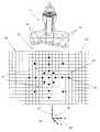
- FIG. 1is a schematic illustration of an embodiment of a three-aperture ultrasound imaging probe and a phantom object being imaged.
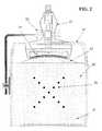
- FIG. 2is a section view of one embodiment of a multiple aperture ultrasound probe with a continuous curvilinear array positioned above a phantom and held in place by a clamp mechanism.
- FIG. 3is a section view of an embodiment of an adjustable multiple aperture imaging probe positioned above a phantom.
- FIG. 4Ais a longitudinal sectional view of a multiple aperture ultrasound imaging probe configured for trans-esophageal ultrasound imaging.
- FIG. 4Bis a longitudinal sectional view of a multiple aperture ultrasound imaging probe configured for trans-rectal ultrasound imaging.
- FIG. 4Cis a longitudinal sectional view of a multiple aperture ultrasound imaging probe configured for intravenous ultrasound.
- FIG. 4Dis a longitudinal sectional view of a multiple aperture ultrasound imaging probe configured for trans-vaginal ultrasound imaging.
- FIG. 4Eis a sectional view of a multiple aperture ultrasound imaging probe configured for imaging round structures or features.
- FIG. 4Fis a plan view of a multiple aperture ultrasound imaging probe with a radial array of transducer elements configured for three-dimensional imaging.
- FIG. 5Ais a cross-sectional view of an ultrasound probe calibration phantom having a docking section with receiving slots for receiving and retaining ultrasound probes to be calibrated.
- FIG. 5Bis a top plan view of the ultrasound probe calibration phantom docking section of FIG. 5A .
- FIG. 6is a process flow diagram of one embodiment of a process for calibrating a multiple aperture ultrasound probe using a static phantom.
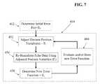
- FIG. 7is a process flow diagram illustrating one embodiment of an iterative optimization process for minimizing an error function by adjusting transducer element position variables.
- FIG. 8is a block diagram illustrating components of an ultrasound imaging system in accordance with some embodiments.
- Calibration of a multiple aperture ultrasound imaging probemay generally comprise determining an acoustic position of each transducer element in the probe.
- Some embodiments of a dynamic calibration processmay generally include the steps of imaging a calibration phantom having a known pattern of reflectors, quantifying an error between known information about the phantom and information obtained from the imaging, and performing an iterative optimization routine to minimize an error function in order to obtain improved transducer element position variables. Such improved transducer element position variables may then be stored for use during subsequent imaging using the calibrated probe.
- the various embodimentsare described herein with reference to ultrasound imaging of various anatomic structures, it will be understood that many of the methods and devices shown and described herein may also be used in other applications, such as imaging and evaluating non-anatomic structures and objects.
- the probes, systems and methods described hereinmay be used in non-destructive testing or evaluation of various mechanical objects, structural objects or materials, such as welds, pipes, beams, plates, pressure vessels, etc.
- an ultrasound transducermay carry their ordinary meanings as understood by those skilled in the art of ultrasound imaging technologies, and may refer without limitation to any single component capable of converting an electrical signal into an ultrasonic signal and/or vice versa.
- an ultrasound transducermay comprise a piezoelectric device.
- ultrasound transducersmay comprise capacitive micromachined ultrasound transducers (CMUT).
- CMUTcapacitive micromachined ultrasound transducers
- Transducersare often configured in arrays of multiple individual transducer elements.
- the terms “transducer array” or “array”generally refers to a collection of transducer elements mounted to a common backing plate. Such arrays may have one dimension (1D), two dimensions (2D), 1.X dimensions (1.XD) or three dimensions (3D). Other dimensioned arrays as understood by those skilled in the art may also be used. Annular arrays, such as concentric circular arrays and elliptical arrays may also be used.
- An element of a transducer arraymay be the smallest discretely functional component of an array. For example, in the case of an array of piezoelectric transducer elements, each element may be a single piezoelectric crystal or a single machined section of a piezoelectric crystal.
- the terms “transmit element” and “receive element”may carry their ordinary meanings as understood by those skilled in the art of ultrasound imaging technologies.
- the term “transmit element”may refer without limitation to an ultrasound transducer element which at least momentarily performs a transmit function in which an electrical signal is converted into an ultrasound signal.
- the term “receive element”may refer without limitation to an ultrasound transducer element which at least momentarily performs a receive function in which an ultrasound signal impinging on the element is converted into an electrical signal. Transmission of ultrasound into a medium may also be referred to herein as “insonifying.” An object or structure which reflects ultrasound waves may be referred to as a “reflector” or a “scatterer.”
- an aperturemay refer to a conceptual “opening” through which ultrasound signals may be sent and/or received.
- an apertureis simply a single transducer element or a group of transducer elements that are collectively managed as a common group by imaging control electronics.
- an aperturemay be a physical grouping of elements which may be physically separated from elements of an adjacent aperture.
- adjacent aperturesneed not necessarily be physically separated.
- transmit aperturemeans an individual element, a group of elements within an array, or even entire arrays with in a common housing, that perform the desired transmit or receive function from a desired physical viewpoint or aperture.
- transmit and receive aperturesmay be created as physically separate components with dedicated functionality.
- any number of send and/or receive aperturesmay be dynamically defined electronically as needed.
- a multiple aperture ultrasound imaging systemmay use a combination of dedicated-function and dynamic-function apertures.
- total aperturerefers to the total cumulative size of all imaging apertures.
- total aperturemay refer to one or more dimensions defined by a maximum distance between the furthest-most transducer elements of any combination of send and/or receive elements used for a particular imaging cycle.
- the total apertureis made up of any number of sub-apertures designated as send or receive apertures for a particular cycle.
- the total aperture, sub-aperture, transmit aperture, and receive aperturewill all have the same dimensions.
- the dimensions of the total aperturemay include the sum of the dimensions of all of the arrays.
- two aperturesmay be located adjacent one another on a continuous array. In still other embodiments, two apertures may overlap one another on a continuous array, such that at least one element functions as part of two separate apertures.
- the location, function, number of elements and physical size of an aperturemay be defined dynamically in any manner needed for a particular application. Constraints on these parameters for a particular application will be discussed below and/or will be clear to the skilled artisan.
- Elements and arrays described hereinmay also be multi-function. That is, the designation of transducer elements or arrays as transmitters in one instance does not preclude their immediate redesignation as receivers in the next instance.
- embodiments of the control system hereininclude the capabilities for making such designations electronically based on user inputs, pre-set scan or resolution criteria, or other automatically determined criteria.
- point source transmissionmay refer to an introduction of transmitted ultrasound energy into a medium from single spatial location. This may be accomplished using a single ultrasound transducer element or combination of adjacent transducer elements transmitting together as a single transmit aperture.
- a single transmission from a point source transmit apertureapproximates a uniform spherical wave front, or in the case of imaging a 2D slice, a uniform circular wave front within the 2D slice.
- a single transmission of a circular or spherical wave front from a point source transmit aperturemay be referred to herein as a “ping” or a “point source pulse.”
- Point source transmissiondiffers in its spatial characteristics from a “phased array transmission” which focuses energy in a particular direction from the transducer element array.
- Phased array transmissionmanipulates the phase of a group of transducer elements in sequence so as to strengthen or steer an insonifying wave to a specific region of interest.
- a short duration phased array transmissionmay be referred to herein as a “phased array pulse.”
- multiple aperture imaging using a series of transmitted pingsmay operate by transmitting a point-source ping from a first transmit aperture and receiving echoes with elements of two or more receive apertures, one or more of which may include some or all elements of a transmit aperture.
- a complete imagemay be formed by triangulating the position of scatterers based on delay times between ping transmission and reception of echoes, the speed of sound, and the relative positions of transmit and receive transducer elements.
- each receive aperturemay form a complete image from echoes of each transmitted ping.
- a single time domain framemay be formed by combining images formed from echoes at two or more receive apertures from a single transmitted ping.
- a single time domain framemay be formed by combining images formed from echoes received at one or more receive apertures from two or more transmitted pings.
- the multiple transmitted pingsmay originate from different transmit apertures.
- FIG. 1illustrates an embodiment of a three-array multiple aperture ultrasound imaging probe 10 and a phantom 20 to be imaged.
- the phantom 20generally includes a pattern of reflectors 30 within a solid or liquid medium 35 .
- a phantom 20may also include one or more “holes”—regions or objects that substantially absorb and do not reflect significant ultrasound signals.
- the probe 10is shown with a left transducer array 12 which may include three transmit apertures labeled ‘n,’ ‘j,’ and ‘k’ (which may be referred to herein by short-hand designations Ln, Lj and Lk).
- a right transducer array 14may also include three transmit apertures ‘n,’ ‘j,’ and ‘k’ (which may be referred to herein by short-hand designations Rn, Rj and Rk). Some or all of the elements of the left transducer array 12 may also be designated as a left receive aperture 13 . Similarly, some or all of the elements of the right transducer array 14 may be designated as a right receive aperture 15 .
- a multiple aperture ultrasound probe 10may include a center transducer array 16 , which may include three transmit apertures labeled ‘n,’ ‘j,’ and ‘k’ (which may be referred to herein by short-hand designations Cn, Cj and Ck). Some or all of the elements of the center transducer array 16 may also be designated as a center receive aperture 17 . It should be understood that each of the three apertures can include any number of transducer elements which may be spaced from one another in one, two or three dimensions.
- any other multiple aperture ultrasound imaging probemay be calibrated using the systems and methods described below.
- FIG. 2illustrates a multiple aperture ultrasound probe 55 with a single large (i.e., larger than an expected coherence width for an intended imaging application) continuous curved array 18 positioned over a phantom 20 .
- FIG. 3illustrates an adjustable multiple aperture ultrasound probe 11 positioned over a phantom 20 .
- FIG. 4Aillustrates a multiple aperture ultrasound probe 100 with one or more transducer arrays 102 positioned at a distal end of an endoscope 104 sized and configured for transesophageal positioning and imaging.
- FIG. 1illustrates a multiple aperture ultrasound probe 55 with a single large (i.e., larger than an expected coherence width for an intended imaging application) continuous curved array 18 positioned over a phantom 20 .
- FIG. 3illustrates an adjustable multiple aperture ultrasound probe 11 positioned over a phantom 20 .
- FIG. 4Aillustrates a multiple aperture ultrasound probe 100
- FIG. 4Billustrates a multiple aperture ultrasound probe 110 with one or more transducer arrays 112 and a housing 114 sized and configured for trans-rectal positioning and imaging.
- FIG. 4Cillustrates a multiple aperture ultrasound probe 120 including one or more transducer arrays 122 and a housing 124 positioned at a distal end of a catheter 126 all of which may be sized and configured for intravenous positioning and imaging.
- FIG. 4Dillustrates a multiple aperture ultrasound probe 130 with one or more transducer arrays 132 and a housing 134 sized and configured for trans-vaginal positioning and imaging.
- FIG. 4Eillustrates a multiple aperture ultrasound probe 140 with a continuous curved transducer array 142 and a housing 144 and a side-mounted cable 146 sized and configured for positioning over curved anatomical structures such as arms and legs.
- FIG. 4Fillustrates a multiple aperture ultrasound probe 150 with a large circular array 152 that may have a concave curvature about two axes.
- the probe of FIG. 4F and other probesmay include transducer elements with substantial displacement along orthogonal axes. Such probes may be particularly suitable for directly obtaining echo data from a three-dimensional volume. Any of these or other ultrasound probes (including single-aperture ultrasound probes) may be calibrated using the systems and methods herein.
- phantommay refer to any substantially static object to be imaged by an ultrasound probe.
- any number of phantoms designed for sonographer trainingare widely commercially available from various suppliers of medical equipment, such as Gammex, Inc. (gammex.com).
- Some commercially available phantomsare made to mimic the imaging characteristics of objects to be imaged such as specific or generic human tissues. Such properties may or may not be required by various embodiments of the invention as will be further described below.
- the term “phantom”may also include other objects with substantially static reflectors, such as a region of a human or animal body with substantially static strong reflectors. An object need not be purpose-built as a phantom to be used as a phantom for the calibration processes described herein.
- a first imagemay be formed by transmitting a first ping from a first transmit aperture Ln and receiving echoes of the first ping at a left receive aperture 13 .
- a second imagemay be formed from echoes of the first ping received at the right receive aperture 15 .
- Third and fourth imagesmay be formed by transmitting a second ping from a second transmit aperture Lj and receiving echoes of the second ping at the left receive aperture 13 and the right receive aperture 15 . In some embodiments, all four images may then be combined to form a single time domain frame.
- a single time domain framemay be obtained from echoes received at any number of receive apertures from any number of pings transmitted by any number of transmit apertures. Time domain frames may then be displayed sequentially on a display screen as a continuous moving image. Still images may also be formed using any of the above techniques.
- the width of a receive aperturemay be limited by the assumption that the speed of sound is the same for every path from a scatterer to each element of the receive aperture. In a narrow enough receive aperture this simplifying assumption is acceptable. However, as receive aperture width increases, an inflection point is reached (referred to herein as the “maximum coherent aperture width” or “coherence width”) at which the echo return paths will necessarily pass though different types of tissue having different speeds of sound. When this difference results in phase shifts in excess of 180 degrees, additional receive elements beyond the maximum coherent receive aperture width will actually degrade the image rather than improve it.
- the coherence widthwill vary depending on an intended imaging application and is difficult if not impossible to predict in advance.
- the full probe widthmay be physically or logically divided into multiple apertures, each of which may be limited to a width less than the maximum coherent aperture width and small enough to avoid phase cancellation of received signals.
- the maximum coherent widthcan be different for different patients and for different probe positions on the same patient.
- a compromise widthmay be determined for a given probe system.
- a multiple aperture ultrasound imaging control systemmay be configured with a dynamic algorithm to subdivide the available elements in multiple apertures into groups that are small enough to avoid significant phase cancellation.
- each image pixelmay be assembled by beamforming received echo data to combine information from echoes received at each of the multiple receive apertures and from each of the multiple transmit apertures.
- receive beamformingcomprises forming a pixel of a reconstructed image by summing time-delayed echo returns on receive transducer elements from a scatterer in the object being examined. The time delays may be determined by the geometry of the probe elements and an assumed value for the speed of sound through the medium being imaged.
- the locus of a single reflectorwill lie along an ellipse with a first focus at the position of the transmit transducer element(s) and the second focus at the position of the receive transducer element.
- echoes of the same reflectorwill also be received by each of the other receive transducer elements of a receive aperture.
- the slightly different positions of each receive transducer elementmeans that each receive element will define a slightly different ellipse for a given reflector.
- Accumulating the results by coherently summing the ellipses for all elements of a common receive aperturewill indicate an intersection of the ellipses for a reflector, thereby converging towards a point at which to display a pixel representing the reflector.
- the echo amplitudes received by any number of receive elementsmay thereby be combined into each pixel value. In other embodiments the computation can be organized differently to arrive at substantially the same image.
- each transmit and receive elementplays an important role in producing an image during ping-based ultrasound imaging
- the quality of an image produced from ping-based imagingis substantially dependent on the accuracy of the information describing the relative positions of the transducer elements.
- Various algorithmsmay be used for combining echo signals received by separate receive elements. For example, some embodiments may process echo-signals individually, plotting each echo signal at all possible locations along its ellipse, then proceeding to the next echo signal. Alternatively, each pixel location may be processed individually, identifying and processing all echoes potentially contributing to that pixel location before proceeding to the next pixel location.
- Image qualitymay be further improved by combining images formed by the beamformer from one or more subsequent transmitted pings, transmitted from the same or a different point source (or multiple different point sources). Still further improvements to image quality may be obtained by combining images formed by more than one receive aperture. An important consideration is whether the summation of images from different pings, different transmit point-sources or different receive apertures should be coherent summation (phase sensitive) or incoherent summation (summing magnitude of the signals without phase information).
- multiple aperture imaging using a series of transmitted pingsmay operate by transmitting a point-source ping from a first transmit aperture and receiving echoes with elements of one or more receive apertures (which may overlap with the transmit aperture).
- a complete imagemay be formed by triangulating the position of scatterers based on delay times between transmission and receiving echoes and the known position of each receive element relative to each point-source transmit aperture. As a result, a complete image may be formed from data received at each receive aperture from echoes of each transmitted ping.
- Images obtained from different unique combinations of a ping and a receive aperturemay be referred to herein as image layers. Multiple image layers may be combined to improve the overall quality of a final combined image.
- the number of image layerscan be the product of the number of receive apertures and the number of transmit apertures (where a “transmit aperture” can be a single transmit element or a group of transmit elements).
- the same ping imaging processesmay also be performed using a single receive aperture.
- Some embodiments of ultrasound probe calibration methods using a phantommay generally include the steps of characterizing the phantom using some known baseline reference data, then imaging the phantom with the probe to be calibrated. An error between the known reference data and data obtained from the generated image may then be quantified and an iterative optimization routine may be used to obtain improved transducer element position information. Such improved transducer element position variables may then be stored for use during subsequent imaging using the calibrated probe.
- FIG. 1illustrates one embodiment of a phantom 20 that may be used for calibrating a multiple aperture probe.
- a phantom 20 for calibrating a multiple aperture probemay include a plurality of reflectors 30 arranged in a two-dimensional pattern within a solid, liquid or gel material 35 that has a consistent and known speed-of-sound.
- the reflectorsmay be made of any material, such as a plastic, metal, wood, ceramic, or any other solid material that is substantially highly reflective of ultrasound waves relative to the surrounding medium.
- reflectors 30may be arranged in the phantom 20 in a pattern that may have characteristics selected to facilitate a calibration process. For example, a non-repeating reflector pattern will allow a calibration process to recognize an imaged position of the reflectors without confusion. For example, a complete grid pattern is highly repetitive because portions of the pattern are identically duplicated merely by shifting one full grid position.
- the pattern of reflectorsmay also comprise a number of reflectors with displacement along the X axis 46 that is approximately equal to a number of reflectors with displacement along the Y axis 47 .
- a pattern in the shape of a cross or a plus signmay be used.
- reflectorsmay be positioned randomly or in other patterns, such as an X-shape, an asterisk, a sunburst, a spiral or any other pattern.
- reflectorsmay also have depth or distinguishable detail in the z-direction 48 .
- the reflectors 30may be rods with longitudinal axes along the z-direction 48 .
- the reflectorsmay be substantially spherical or uniform three-dimensional shapes.
- an arrangement of intersecting wires or rodsmay be used to form a distinguishable pattern in three-dimensional space within a phantom.
- the reflectors 30 in the calibration phantom 20may be of any size or shape as desired.
- the reflectors 30may have a circular diameter that is on the same order of magnitude as the wavelength of the ultrasound signals being used. In general, smaller reflectors may provide better calibration, but in some embodiments the precise size of the reflectors need not be an important factor.
- all reflectors 30 in the phantommay be the same size as one another, while in other embodiments, reflectors 30 may be provided in a variety of sizes.
- the physical size and location of the reflectors in the phantom 20may be determined by mechanical measurement of the phantom (or by other methods, such as optical measurement or ultrasonic measurement using a known-calibrated system) prior to, during or after construction of the phantom.
- Reflector position reference datamay then by obtained by storing the reflector location information within a memory device accessible by software or firmware performing a calibration process.
- Such reference datamay include information such as the position, size, orientation, arrangement or other information about the reflectors and/or holes in the phantom.
- Reference datamay be represented or stored as a reference image or as a series of data points. Alternatively, reference data may be extracted from a reference ultrasound image.
- a reference image of the phantommay be obtained using a probe or an array within a probe that is known to be well-calibrated. In other embodiments, a reference image of the phantom may be obtained using a selected group of elements of the probe. Reflector size and/or location information may then be determined from the reference image for use in calibrating remaining elements of the probe or a different probe.
- a reference imagemay be obtained by retrieving previously-determined reflector position data from a memory device.
- a reference imagemay be obtained by imaging the phantom using a sub-set of all elements in a probe.
- a reference imagemay be obtained by imaging the phantom 20 using only one of the arrays (e.g., the center array 16 , the left array 12 or the right array 14 ).
- a reference imagemay be obtained by imaging the phantom 20 using only a small group of transducer elements of the array.
- a group of elements near the center of the curved arraymay be used as transmit and/or receive elements for obtaining a reference image.
- a reference imagemay be obtained using a single adjustable array 19 of an adjustable probe 11 such as that shown in FIG. 3 . Reference images may be obtained using any multiple aperture ultrasound imaging probe in a similar manner.
- the phantommay be mounted in an enclosure that includes a probe-retaining portion 50 .
- a mounting bracket 52may also be provided to securely hold the probe 55 in a consistent position relative to the phantom 20 during a calibration process. Any mechanical bracket may be used.
- a coupling gel and/or a gel or fluid-filled standoff 42may be used to provide a continuous medium through which the ultrasound signals will pass. The coupling gel and/or standoff 42 should have approximately the same speed-of-sound as the phantom medium.
- a standoff 42may be a liquid or gel-filled bag.
- FIG. 5Aillustrates an alternative arrangement comprising a docking section 342 having a plurality of receiving slots 310 designed to receive probes of specific shapes.
- the docking section 342may be made of the same material as the material of the phantom 20 .
- the docking section 342may be made of a material having the same speed-of-sound characteristics as the phantom 20 .
- many probe receiving slots 310may be provided for a single docking section 342 .
- each probe receiving slot 310may be sized, shaped, and otherwise configured to receive one or more specific ultrasound probes.
- FIG. 6is a process flow diagram illustrating an embodiment of a process 400 for calibrating a multiple aperture probe using a phantom.
- some embodiments of the process 400may comprise the steps of obtaining reference data 402 that characterizes known information about the phantom (such as reflector or hole positions, sizes, etc.), insonifying the phantom with a test transmit (TX) aperture 404 , receiving echoes with a test receive (RX) aperture 405 , at least temporarily storing the received echo data 406 , forming a test image of the reflectors by beamforming the echo data 408 , determining an error function 412 based on a comparison of the generated image and the reference data, and minimizing the error function 414 to obtain improved transducer element position variables 416 .
- TXtest transmit
- RXtest receive
- the resulting improved element position informationmay be stored in a memory device for subsequent use by a beamforming process.
- Steps 404 - 416may then be repeated for each additional transmit and/or aperture in the probe, and the position of each transducer element in each transmit and/or receive aperture within the probe may be determined relative to a common coordinate system.
- the process 400may be entirely automated in software or firmware. In other embodiments, at least some steps may involve human participation, such as to identify or to quantify an error between an obtained image and a reference image. In other embodiments, a human user may also be called upon to determine whether a resulting image is “good enough” or whether the calibration process should be repeated or continued.
- the process 400may be used to calibrate the position of one or more test transmit apertures, one or more test receive apertures, or both.
- the choice of which type of aperture to calibratemay depend on factors such as the construction of the probe, the number of transmit or receive apertures, or other factors.
- the definitions of test transmit apertures and test receive apertures used for the calibration processmay be, but need not necessarily be the same as the definition of apertures used for normal imaging with the probe. Therefore, the phrase “test aperture” as used herein may refer to either a transmit test aperture or a receive test aperture unless otherwise specified.
- the test transmit aperture and the test receive aperture used during the process 400 of FIG. 6may be substantially close to one another.
- the test transmit aperture and the test receive aperturemay be within an expected coherence width of an intended imaging application relative to one another.
- a receive aperturemay include all elements on a common array (e.g., elements sharing a common backing block).
- a receive aperturemay comprise elements from two or more separate arrays.
- a receive aperturemay include a selected group of transducer elements along a large continuous array.
- the test transmit aperture and the test receive apertureneed not be close to one another, and may be spaced from one another by a distance greater than any anticipated coherence width.
- the coherence widthneed not be a significant consideration.
- a single transmit test aperturemay be used to obtain both a reference image and data from which a test image may be formed.
- a first receive aperturemay be used to form a reference image
- a second (or third, etc.) receive aperturemay be used to form or obtain test image data.
- a single receive aperturemay be used for obtaining both a reference image and data for a test image if different transmit apertures are used for the reference image and the test image data.
- the test transmit aperture and the test receive apertureneed not necessarily be near one another.
- reference imagesmay be obtained using transmit and receive elements of a first array, while data for test images may be obtained using transmit and receive elements of a second array, where the second array is a test array to be calibrated.
- the step of obtaining reference data 402may comprise retrieving reference data from a data storage device.
- a data storage devicemay be physically located within a calibration controller, within an ultrasound imaging system, within a probe, or on a separate storage device that may be accessible via a wired or wireless network connection.
- the step of obtaining reference data 402may comprise imaging the phantom with a reference group of transducer elements.
- the step of insonifying the phantom with a test transmit aperture 404may comprise transmitting one or more pings from one or more transmit elements of a transmit aperture.
- a single transmit aperturemay typically comprise one, two, three or a small number of adjacent elements.
- the memory devicemay be any volatile or non-volatile digital memory device in any physical location that is electronically accessible by a computing device performing the imaging and calibration processes.
- the received echo datamay then be beamformed and processed to form a test image 408 .
- the steps of insonifying the phantom from a test transmit aperture 404 and receiving echoes with a test receive aperture 405may be repeated using multiple combinations of different transmit apertures and/or receive apertures, and images obtained 408 from such transmitting and receiving may be combined in a process referred to as image layer combining prior to proceeding to subsequent steps of the process 400 .
- the error functionmay be determined from some difference between the phantom reference data (e.g., information known about the position of reflectors in the phantom) and an image of the phantom obtained with the test receive aperture.
- the choice of error functionmay be based on characteristics of the phantom used, available processing capabilities, a chosen optimization method or many other factors.
- a modified least squares optimization methodmay be used to minimize an error function based on the square of an aggregated straight-line error distance between the expected reflector center and an imaged reflector center. For example, after forming an image of the phantom with the echoes received at a test receive aperture, the system may identify the location of each reflector in the image by identifying the brightest point in the image of approximately the expected size in approximately the expected location of each known reflector. Once each reflector is identified, an error between the imaged position and the expected position of each reflector may be determined. In some embodiments, these individual reflector-position errors may then be aggregated into a collective reflector pattern error, such as by summing all individual reflector errors.
- the individual errorsmay be aggregated using any other function, such as taking a maximum error, an average, or a weighted sum of individual errors. For example, if a phantom has some reflectors that are more difficult to detect than others, difficult-to-detect reflectors may be given less weight in the aggregate error function so as to obtain a more balanced result.
- such individual and/or aggregate errorsmay be either scalar or vector quantities.
- reflector imagesmay be sought within a predetermined search area surrounding the expected location of each reflector.
- the shape and size of a search areamay be defined based on the known pattern of reflectors and the distance between reflectors.
- images of reflectorsmay be identified by artificial intelligence or probability analysis using information about nearby reflectors and the known pattern of reflectors.
- the search area surrounding each reflectormay comprise a circular, rectangular or other geometric area centered on the point of a center of an expected reflector position. The size of a search area may be selected to be larger than the imaged reflectors, but typically small enough that adjacent search areas do not overlap.
- forming an image 408may be limited to beamforming only echoes representing search areas surrounding the expected positions of reflectors in the phantom (rather than beamforming an entire image field).
- beamformingmay be limited to a search area defining the overall pattern of reflectors. For example, this may be accomplished in some embodiments by beamforming vertical and horizontal pixel bands slightly wider than the expected position of the pins in FIG. 1 .
- the error functionmay be defined based on one or more simplifying assumptions. For example, instead of detecting and optimizing based on the two-dimensional or three-dimensional position of each individual reflector, a line or curve may be fit to the series of reflectors. For example, using the phantom layout shown in FIG. 1 , a vertical line may be drawn through the pins spaced along the Y axis. In practice, reflectors in the approximate location of the vertical pins may be detected, a fit line through the detected reflectors may be calculated, and the quality of the fit line may be evaluated using a factor such as a coefficient of determination (R 2 value). An error function may then be defined based on the R 2 value of the line connecting the vertical pins.
- R 2 valuecoefficient of determination
- a similar approachmay be taken for the horizontal pins.
- the simplifying assumption of pins fit to a linemay ignore the spacing between the pins along the fit line, and may therefore be less precise than methods defining an error function based on two-dimensional position of each pin.
- optimizing based on a single line segmentmay be substantially faster in processing terms than optimizing based a plurality of individual pin reflector positions. Therefore, such simplifications may still provide valuable information in exchange for a faster processing time.
- polynomial curves, circles or other mathematically-defined geometric shapesmay be used as simplifications for representing a pattern of reflectors within a phantom.
- the error functionmay be defined as some quantity other than reflector position.
- an error functionmay be defined as a sum of absolute value differences in brightness of the individual imaged reflectors relative to a reference image.
- an error functionmay be defined based on a complete collective reflector pattern.
- a phantommay be designed to contain an array of reflectors representing a reference number in binary form (i.e., a reflector may represent a ‘1’ and the absence of a reflector at a grid position may represent a ‘0’).
- a calibration processmay be configured to ‘read’ the binary values, and the error function may be defined as the number of bits different from the expected reference number.
- an error functionmay be at least partially based on a pattern of “holes”—regions of the phantom that absorb the ultrasound energy. Many other error functions may also be used.
- FIG. 7illustrates one embodiment of an iterative optimization process 414 for minimizing an error function by adjusting transducer element position variables.
- the process 414may proceed to iteratively seek a minimum of an error function by making incremental adjustments to one or more variables describing the position of the elements of the test transmit and/or receive aperture.
- the processmay adjust 452 one or more initial test aperture element position variables (P 0 ) to obtain new test aperture element position variables (P 1 ).
- the stored received echo datafrom 406 in FIG.
- a new error function(E 1 ) may be quantified 456 and then evaluated or stored 460 before returning to step 452 for a second iteration.
- the nature of the adjustments 452 and the error evaluations 460may depend on the type of optimization routine being used.
- adjustments to the element position variablesmay be essentially random in each iteration (i.e., with no connection to adjustments made in prior iterations). Such random adjustments may be made within a predetermined range of values relative to current element position data based on expectations of the possible degree of mis-calibration of existing element position data.
- an error function obtained from each iterationmay be stored, and a minimum error function may be identified by comparing the results of all iterations.
- adjustmentsmay be directly based on information from previous iterations, such as an evaluation of the magnitude and/or direction of a change in the error value. For example, in some embodiments, if the new error function E 1 is less than the initial error function E 0 , then the adjustment made in step 452 may be determined to be a good adjustment and the process may repeat for more iterations making further incremental adjustments to the position variable(s). If the new error function E 1 obtained in the first iteration is not less than the initial error function E 0 (i.e. E 1 ⁇ E 0 ), then it may be assumed that the adjustment of step 452 was made in the wrong direction.
- the original element position variable(s) P 0may be adjusted in a direction opposite to that tried during the first iteration. If the resulting new error function E 2 is still not smaller than the initial error function E 0 , then the error function is at a minimum (at least with respect to the adjusted element position variable(s)). In such a case, the error minimization process may be stopped, and the last good position variables may be stored as the new transducer element positions.
- the process 414may be repeated through as many iterations as needed until the error function is minimized. In other embodiments, the process 414 may be stopped after a fixed number of iterations. As will be clear to the skilled artisan, multiple ‘optimum’ solutions may exist. As a result, in some embodiments, the iterative calibration process may be repeated multiple times, and the results of the several calibrations may be compared (automatically using image processing techniques or manually by a person) to identify a suitable solution. In any event, it is not necessary to identify the absolute optimal result.
- the position of transducer elementsmay be described by multiple variable quantities. Ultimately, it is desirable to know the acoustic position (which may be different than the element's apparent mechanical position) of each transducer element relative to some known coordinate system. Thus, in some embodiments, the acoustic position of each transducer element may be defined by an x, y, and z position (e.g., with reference to a Cartesian coordinate system 45 such as that shown in FIGS. 1-3 ). In adjusting such quantities during the optimization process 414 , position variables may be adjusted individually or in groups.
- Performing the optimization process by adjusting the x, y and z position of each transducer elementmay be somewhat computationally intensive, since a single aperture may contain hundreds of individual elements. This may result in the iterative adjustment of several hundred if not thousands of variables. This is particularly true for probes with 2D arrays (i.e., those with transducer elements spaced from one another in X and Z directions), curved 1D or 2D arrays (i.e., arrays with curvature about either the X or the Z axis), and 3D arrays (i.e., probes with curvature about two axes). While potentially computationally intensive, the various embodiments herein may be used to calibrate any ultrasound probe with large continuous planar or curved 1D or 2D arrays as well as large continuous 3D arrays with curvature about two axes.
- some embodimentsmay employ one or more simplifying assumptions. For example, in some embodiments it may be assumed that element position relationships within a single array remain fixed relative to one another such that an array with a common backing block will only move, expand or contract uniformly. In some embodiments, it may also be assumed that the elements are uniformly distributed across the array. Using such assumptions, locating a center point of an array, a width of the array and an angle of the array surface relative to a known datum may provide sufficient information about the acoustic position of each element. For example (with reference to FIG.
- the position of all elements in the left array 12may be assumed based on overall array position variables, which may include array width (‘w’), the position of the array's center (i) in the scan plane (i.e., the X-Y plane), and the angle of the array surface in the scan plane relative to some baseline ( ⁇ ). If it is assumed that the acoustic centers of elements are uniformly distributed across the array with a consistent spacing in the X direction for a 1D array or in the X and Z directions for a 2D array, then the acoustic position of each transducer element may be mathematically expressed in terms of the above four variables (center-X, center-Y, width and angle).
- a fifth variable describing the position of an array's center in the Z-directionmay also be used.
- one or more of these variablesmay be treated as fixed in some embodiments.
- an error function minimizing processneed only iteratively optimize four or five transducer element position variables. In the case of different probe constructions, different simplifying assumptions may also be used.
- two or more optimization processesmay be combined in parallel or sequential processes in order to improve processing efficiency, calibration precision, or both.
- a two-stage optimization processmay be used in which a first stage provides a coarse improvement to element position variables while relying on one or more simplifying assumptions.
- a second stagemay then provide a more detailed improvement to the element position variables while relying on fewer simplifying assumptions, but starting from the improved information obtained during the first stage.
- multiple reflectorsmay be represented with a single geometric shape such as a line, and the spacing between transducer elements may be treated as fixed (i.e., such values are not varied during the optimization).
- a second stage processmay then be performed, in which the position of each pin is optimized by varying element position variables including the spacing between transducer elements.
- a similar calibration processmay be used to calibrate a probe 55 with a large continuous array 18 , such as that illustrated in FIG. 2 .
- the continuous array 18lacks physical separations, the same simplifying assumptions discussed above with regard to the probe of FIG. 1 may not apply.
- the probe 55 of FIG. 2may be calibrated by making simplifying assumptions about the shape of the large array, and apertures may be defined by using relatively small groups of elements at various positions along the array.
- the x-y position of each element in an aperturemay be used as element position parameters to be optimized. Such selected apertures may then be calibrated in substantially the same manner described above.
- element position variablesmay be adjusted 452 either in series or in parallel.
- position variablesare to be adjusted in series
- only one variablemay be adjusted during each iteration.
- a single variablemay be optimized (i.e., the error function may be minimized by adjusting only that single variable) before proceeding to the next variable.
- the two or more variablesmay each be adjusted during each iteration.
- those two variablesmay be optimized before proceeding to optimization of other variables.
- all variablesmay be optimized in parallel.
- position variablesmay be optimized using a combination of series and parallel approaches. It should be noted this distinction between series and parallel optimization approaches should not be confused with parallel computer processing. Depending on computing hardware used, even optimizations performed in series as described above may be computed simultaneously using separate threads in parallel processors.
- the process of FIG. 6may be repeated for each remaining array or aperture individually. For example, using the three-array probe of FIG. 1 , the calibration process may be repeated for the right array 14 and then again for the left array 12 .
- updated element position data for each subsequently-tested arraymay be determined and stored relative to a common coordinate system such that the position of any element in the probe may be determined relative to any other.
- the calibration processmay determine the center of the center array, which may be used as the center of the coordinate system for the other arrays.
- the angle of the center arraymay also be used as a datum against which angles of the other arrays may be defined.
- the positions and orientations of the aperturesmay be determined relative to some other datum independent of any array.
- element positionsmay ultimately be defined using any coordinate system centered around any point relative to the probe.
- transducer element position adjustmentsmay be obtained and stored in the form of new corrected element position coordinates.
- position adjustmentsmay be obtained and stored as coefficients to be added to or multiplied with previous element position coordinates.
- “factory” element position datamay be stored in a read-only memory device in a location readable by an ultrasound system, such as a ROM chip within a probe housing. Such factory position data may be established at the time of manufacturing the probe, and subsequent calibration data may be stored as coefficients that may be applied as adjustments to the factory position data.
- adjusted element position data for each transducer element in a probemay be stored in a non-volatile memory device located within a probe housing. In other embodiments, adjusted element position data may be stored in a non-volatile memory device located within an imaging system, on a remote server, or in any other location from which the information may be retrieved by an imaging system during image beamforming.
- an “adjustable probe”may be any ultrasound imaging probe in which the position and/or orientation of one or more transducer arrays or transducer elements may be changed relative to one or more other transducer arrays or elements.
- Many adjustable probe configurations beyond that shown in FIG. 3are possible and may be designed for specific imaging applications.
- one or more of the arrays in an adjustable probemay be permanently secured to the housing in a fixed orientation and position (e.g., the center array or the left or right end array), while the remaining arrays may be movable to conform to a shape of an object to be imaged.
- the fixed arraywould then be in a permanently known position and orientation.
- the position and orientation of one or more arraysmay be known based on one or more position sensors within an adjustable probe.
- the known-position array(s)may then be used to obtain a reference image of a phantom (or even a region of an object or patient to be imaged), and an optimization process may be used to determine an adjusted position of the movable arrays.
- a sonographermay adjust the adjustable arrays of an adjustable probe to conform to a patient's anatomy. Then, during normal imaging, a reference image may be obtained using the known array, and positions of the remaining arrays may be determined by an optimization routine configured to minimize an error function (e.g., using an optimization routine as described above) defining an error between the reference image obtained from the center array and images obtained from each adjustable array.
- an optimization routineconfigured to minimize an error function (e.g., using an optimization routine as described above) defining an error between the reference image obtained from the center array and images obtained from each adjustable array.
- a sonographermay adjust the arrays of an adjustable probe to conform to a patient's anatomy. The sonographer may then place the probe onto a phantom that includes a conformable section configured to receive the probe in its adjusted position.
- a conformable sectionmay include a flexible bag containing a liquid or gel selected to transmit ultrasound signals at substantially the same speed of sound as the material of the phantom.
- a calibration processmay then be initiated, and the position of each adjustable array may be determined by an iterative optimization routine in which reference data describing the phantom is compared with images of the phantom obtained with each array.
- the element-position informationmay change between performing a calibration operation and capturing raw ultrasound data. For example, a probe may be dropped, damaged or may be otherwise altered (such as by thermal expansion or contraction due to a substantial temperature change) before or during a raw sample data capture session. In some embodiments, the probe may be re-calibrated using captured, stored raw echo data as described below.
- an ultrasound imaging system 500may include a raw data memory device 502 configured to capture and store raw, un-beamformed echo data.
- an ultrasound imaging system configured to perform an optimization-based calibrationmay include a transmit control subsystem 504 , a probe subsystem 506 , a receive subsystem 508 , an image generation subsystem 510 , a video subsystem 512 , a calibration memory 530 and a calibration processor 540 .
- the image generation subsystemmay include a beamformer 520 (hardware or software) and an image-layer combining block 522 .
- a calibration systemmay be provided independently of an imaging system.
- components such as the video subsystem 512may be omitted.
- Other components shown in FIG. 8may also be omitted where practicable.
- the transmit control subsystem 504may direct the probe to transmit ultrasound signals into a phantom. Echoes returned to the probe may produce electrical signals which are fed into the receive sub-system 508 , processed by an analog front end, and converted into digital data by an analog-to-digital converter. The digitized echo data may then be stored in a raw data memory device 502 . The digital echo data may then be processed by the beamformer 520 in order to determine the location of each reflector so as to form an image. In performing beamforming calculations, the beamformer may retrieve calibration data from a calibration memory 530 . The calibration data may describe the position of each transducer element in the probe. In order to perform a new calibration, the calibration processor may receive image data from the image formation block 520 or from an image buffer memory device 526 which may store single image frames and/or individual image layers.
- the calibration processormay then perform an optimization-based calibration routine. Once a calibration process is complete, new calibration information may be stored in the calibration memory device 530 for use in subsequent imaging processes or in additional calibration processes.
- raw echo data of a phantommay be captured and stored along with raw echo data from a target object imaging session (e.g., with a patient). Capturing and storing raw echo data of a phantom before and/or after an imaging session may allow for later optimization of the imaging-session data. Such optimization may be applied at any point after the imaging session using the stored raw data and the methods described above.
- an ultrasound imaging system 500may comprise an ultrasound probe 506 which may include a plurality of individual ultrasound transducer elements, some of which may be designated as transmit elements, and others of which may be designated as receive elements.
- each probe transducer elementmay convert ultrasound vibrations into time-varying electrical signals and vice versa.
- the probe 506may include any number of ultrasound transducer arrays in any desired configuration.
- a probe 506 used in connection with the systems and methods described hereinmay be of any configuration as desired, including single aperture and multiple aperture probes.
- the transmission of ultrasound signals from elements of the probe 506may be controlled by a transmit controller 504 .
- the probe elementsmay generate time-varying electric signals corresponding to the received ultrasound vibrations.
- Signals representing the received echoesmay be output from the probe 506 and sent to a receive subsystem 508 .
- the receive subsystem 508may include multiple channels. Each channel may include an analog front-end device (“AFE”) 509 and an analog-to-digital conversion device (ADC) 511 .
- AFEanalog front-end device
- ADCanalog-to-digital conversion device
- each channel of the receive subsystem 508may also include digital filters and data conditioners (not shown) after the ADC 511 . In some embodiments, analog filters prior to the ADC 511 may also be provided.
- each ADC 511may be directed into a raw data memory device 502 .
- one independent channel of the receive subsystem 508may be provided for each receive transducer element of the probe 506 .
- two or more transducer elementsmay share a common receive channel.
- the ultrasound imaging systemmay store digital data representing the timing, phase, magnitude and/or the frequency of ultrasound echo signals received by each individual receive element in a raw data memory device 502 before performing any further beamforming, filtering, image layer combining or other image processing.
- information about one or more ultrasound transmit signals that generated a particular set of echo datamay also be stored in a memory device, such as the raw data memory device 502 or another memory device.
- a memory devicesuch as the raw data memory device 502 or another memory device.
- information about a transmitted ping that produced a particular set of echoesmay include the identity and/or position of one or more a transmit elements as well as a frequency, magnitude, duration or other information describing a transmitted ultrasound signal.
- Transmit datais collectively referred herein to as “TX data”.
- TX datamay be stored explicitly in the same raw data memory device in which raw echo data is stored.
- TX data describing a transmit signalmay be stored as a header before or as a footer after a set of raw echo data generated by the transmit signal.
- TX datamay be stored explicitly in a separate memory device that is also accessible to a system performing a beamforming process.
- transmit datais stored explicitly, the phrases “raw echo data” or “raw data” may also include such explicitly stored TX data.
- TX datamay also be stored implicitly. For example, if an imaging system is configured to transmit consistently defined ultrasound signals (e.g., consistent magnitude, shape, frequency, duration, etc.) in a consistent or known sequence, then such information may be assumed during a beamforming process. In such cases, the only information that needs to be associated with the echo data is the position (or identity) of the transmit transducer(s). In some embodiments, such information may be implicitly obtained based on the organization of raw echo data in a raw data memory.
- consistently defined ultrasound signalse.g., consistent magnitude, shape, frequency, duration, etc.
- a systemmay be configured to store a fixed number of echo records following each ping.
- echoes from a first pingmay be stored at memory positions 0 through ‘n’ (where ‘n’ is the number of records stored for each ping), and echoes from a second ping may be stored at memory positions n+1 through 2n+1.
- one or more empty recordsmay be left in between echo sets.
- received echo datamay be stored using various memory interleaving techniques to imply a relationship between a transmitted ping and a received echo data point (or a group of echoes).
- a collection of echo records corresponding to echoes of a single transmitted ping received by a single receive elementmay be referred to herein as a single “echo string.”
- a complete echo stringmay refer to all echoes of the single ping received by the receive element, whereas a partial string may refer to a sub-set of all echoes of the single ping received by the receive element.
- the time at which each echo data point was receivedmay be inferred from the position of that data point in memory.
- the same techniquesmay also be used to implicitly store data from multiple receive channels in a single raw data memory device.
- the raw echo data stored in the raw data memory device 520may be in any other structure as desired, provided that a system retrieving the echo data is able to determine which echo signals correspond to which receive transducer element and to which transmitted ping.
- position data describing the position of each receive transducer elementmay be stored in the calibration memory device along with information that may be linked to the echo data received by that same element.
- position data describing the position of each transmit transducer elementmay be stored in the calibration memory device along with information that may be linked to the TX data describing each transmitted ping.
- each echo string in the raw data memory devicemay be associated with position data describing the position of the receive transducer element that received the echoes and with data describing the position of one or more transmit elements of a transmit aperture that transmitted the ping that produced the echoes.
- Each echo stringmay also be associated with TX data describing characteristics of the transmitted ping.
- a probemay be calibrated using raw echo data stored in a memory device without raw data of a phantom image. Assuming at least one array (or one portion of an array) is known or assumed to be well-calibrated, nearly any image data with a pattern of strong reflectors may be used to calibrate second, third or further arrays or array segments. For example, echo data from the known-calibrated aperture, array or array segment may be beamformed to obtain a reference image. Stored echo data from the remaining apertures/arrays may then be calibrated using any of the methods described above to calibrate the position of the remaining arrays, apertures or array segments relative to the first.
- a probeBy performing a calibration process using stored echo data, a probe may be calibrated even when neither the probe itself nor the patient (or other imaged object) is physically present proximate to the device performing the re-beamforming and image processing.
- the steps of insonifying a phantom 404 , and receiving echoes 405may be omitted from the process 400 of FIG. 6 at the time of a calibration process, since those steps were performed during the imaging session in which the raw data was captured.
Landscapes
- Health & Medical Sciences (AREA)
- Life Sciences & Earth Sciences (AREA)
- Engineering & Computer Science (AREA)
- Physics & Mathematics (AREA)
- Medical Informatics (AREA)
- Surgery (AREA)
- Veterinary Medicine (AREA)
- Pathology (AREA)
- Biomedical Technology (AREA)
- Heart & Thoracic Surgery (AREA)
- Nuclear Medicine, Radiotherapy & Molecular Imaging (AREA)
- Molecular Biology (AREA)
- Biophysics (AREA)
- Animal Behavior & Ethology (AREA)
- General Health & Medical Sciences (AREA)
- Public Health (AREA)
- Radiology & Medical Imaging (AREA)
- Gynecology & Obstetrics (AREA)
- High Energy & Nuclear Physics (AREA)
- Optics & Photonics (AREA)
- Computer Networks & Wireless Communication (AREA)
- General Physics & Mathematics (AREA)
- Radar, Positioning & Navigation (AREA)
- Remote Sensing (AREA)
- Ultra Sonic Daignosis Equipment (AREA)
- Investigating Or Analyzing Materials By The Use Of Ultrasonic Waves (AREA)
Abstract
Description
This application claims the benefit of U.S. Provisional Patent Application No. 61/681,986, filed on Aug. 10, 2012, titled “Calibration of Multiple Aperture Ultrasound Probes”, the contents of which are incorporated by reference herein.
All publications and patent applications mentioned in this specification are herein incorporated by reference to the same extent as if each individual publication or patent application was specifically and individually indicated to be incorporated by reference.
This disclosure generally relates to ultrasound imaging systems and more particularly to systems and methods for calibrating a multiple aperture ultrasound probe.
In conventional ultrasonic imaging, a focused beam of ultrasound energy is transmitted into body tissues to be examined and the returned echoes are detected and plotted to form an image. While ultrasound has been used extensively for diagnostic purposes, conventional ultrasound has been greatly limited by depth of scanning, speckle noise, poor lateral resolution, obscured tissues and other such problems.
In order to insonify body tissues, an ultrasound beam is typically formed and focused either by a phased array or a shaped transducer. Phased array ultrasound is a commonly used method of steering and focusing a narrow ultrasound beam for forming images in medical ultrasonography. A phased array probe has many small ultrasonic transducer elements, each of which can be pulsed individually. By varying the timing of ultrasound pulses (e.g., by pulsing elements one by one in sequence along a row), a pattern of constructive interference is set up that results in a beam directed at a chosen angle. This is known as beam steering. Such a steered ultrasound beam may then be swept through the tissue or object being examined. Data from multiple beams are then combined to make a visual image showing a slice through the object.
Traditionally, the same transducer or array used for transmitting an ultrasound beam is used to detect the returning echoes. This design configuration lies at the heart of one of the most significant limitations in the use of ultrasonic imaging for medical purposes: poor lateral resolution. Theoretically, the lateral resolution could be improved by increasing the width of the aperture of an ultrasonic probe, but practical problems involved with aperture size increase have kept apertures small. Unquestionably, ultrasonic imaging has been very useful even with this limitation, but it could be more effective with better resolution.
A method of calibrating an ultrasound probe is provided, comprising the steps of placing a first array and a second array of the ultrasound probe in position to image a phantom, each of the first and second arrays having a plurality of transducer elements, imaging the phantom with the first array to obtain a reference image, wherein imaging is dependent on data describing a position of each transducer element of the first array, imaging the phantom with the second array to obtain a test image, wherein imaging is dependent on data describing a position of each transducer element of the second array, quantifying a first error between the reference image and the test image; iteratively optimizing the data describing the position of each transducer element of the second array until the first error is at a minimum.
In some embodiments, the method further comprises imaging the phantom with a third array of the ultrasound probe to obtain a second test image, the third array having a plurality of transducer elements, quantifying a second error between the reference image and the second test image and iteratively optimizing data describing a position of each element of the third array until the second error is minimized.
In some embodiments, the method further comprises storing raw echo data received while imaging the phantom with the second array.
In one embodiment, the iteratively optimizing step comprises adjusting the data describing the position of the transducer elements of the second array to create first adjusted position data, re-beamforming the stored echo data using the first adjusted position data to form a second test image of the reflectors, quantifying a second error between the second test image and the reference image, and determining whether the second error is less than the first error.
In one embodiment, adjusting the data describing the position of the transducer elements of the second array includes adjusting a position of a reference point of the array and an angle of a surface of the array, but does not include adjusting a spacing between the elements of the second array.
In some embodiments, the method further comprises, after a first iteratively optimizing step, performing a second iteratively optimizing step comprising adjusting the first adjusted position data, including adjusting a spacing between at least two transducer elements of the second array to create second adjusted position data, re-beamforming the stored echo data using the second adjusted position data to form a third test image of the reflectors, quantifying a third error between the third test image and the reference image, and determining whether the third error is less than the second error.
In one embodiment, iteratively optimizing the transducer element position data comprises optimizing using a least squares optimization process.
In other embodiments, quantifying the first error comprises quantifying a distance between positions of reflectors in the reference image relative to positions of the same reflectors in the test image. In some embodiments, quantifying the first error comprises quantifying a difference in brightness between reflectors in the reference image and reflectors in the test image. In additional embodiments, quantifying the first error comprises quantifying a difference between a pattern of reflectors and holes in the reference image compared with a pattern of holes and reflectors in the test image.
In one embodiment, the reference image and the test image are three-dimensional volumetric images of a three-dimensional pattern of reflectors, holes, or both reflectors and holes.
In other embodiments, wherein the phantom comprises living tissue.
In some embodiments, the method further comprises identifying positions of reflectors in the phantom and fitting a mathematically defined curve to a detected pattern of reflectors.
In one embodiment, the curve is a straight line.
In other embodiments, the step of quantifying a first error comprises calculating a coefficient of determination that quantifies a degree of fit of the curve to the pattern of reflectors.
A method of calibrating an ultrasound probe is provided, comprising the steps of insonifying a plurality of reflectors of a phantom with the ultrasound probe, receiving echo data with the ultrasound probe, storing the echo data, beamforming the stored echo data using first transducer element position data to form an image of the reflectors, obtaining reference data describing the reflectors, quantifying an error between the image and the reference data, and iteratively optimizing the transducer element position data based on the quantified error.
In some embodiments, the iteratively optimizing step comprises iteratively optimizing the transducer element position data with a least squares optimization process.
In one embodiment, the iteratively optimizing step comprises adjusting the transducer element position data, re-beamforming the stored echo data using the adjusted transducer element position data to form a second image of the reflectors, quantifying a second error based on the second image, and evaluating the second error to determine whether the adjusted transducer element position data improves the image.
In some embodiments, adjusting the transducer element position data comprises adjusting an array horizontal position variable, an array vertical position variable and an array angle variable. In other embodiments, adjusting the transducer element position data does not comprise adjusting a spacing between adjacent transducer elements on a common array.
In one embodiment, the reference data is based on physical measurements of the phantom.
In some embodiments, the method further comprises deriving the reference data from a reference image of the phantom.
In one embodiment, the reference image is obtained using a different group of transducer elements of the probe than a group of transducer elements used for the insonifying and receiving steps.
In additional embodiments, the step of iteratively optimizing the transducer element position data comprises using a least squares optimization process.
In some embodiments, the method further comprises identifying positions of reflectors in the phantom and fitting a mathematically defined curve to a detected pattern of reflectors. In one embodiment, the curve is a straight line.
In some embodiments, the step of quantifying a first error comprises calculating a coefficient of determination that quantifies a degree of fit of the curve to the pattern of reflectors.
A method of calibrating ultrasound imaging data is also provided, comprising the steps of retrieving raw echo data from a memory device, the raw echo data comprising a plurality of echo strings, each echo string comprising a collection of echo records corresponding to echoes of a single ultrasound ping transmitted from a single transmit aperture and received by a single receive element, retrieving first calibration data describing a position of each receive transducer element corresponding to each echo string, retrieving second calibration data describing a position of at least one transducer element corresponding to a transmitted ping associated with each echo string, forming a reference image by beamforming a first collection of echo strings corresponding to a first group of receive transducer elements, wherein beamforming comprises triangulating a position of reflectors based on the first and second calibration data, forming a test image by beamforming a second collection of echo strings corresponding to a second group of transducer elements that is not identical to the first group of transducer elements, quantifying first error between the reference image and the test image, adjusting first calibration data to describe adjusted positions for the elements of the second group, re-beamforming the test image with the adjusted positions for the elements of the second group to obtain a second test image, quantifying a second error between the second test image and the reference image, and evaluating the new error to determine whether the second error is less than the first error.
In some embodiments, the method is performed without any physical or electronic connection to a probe used to create the raw echo data.
In some embodiments, there is no ultrasound probe connected to the memory device.
An ultrasound probe calibration system is provided, comprising an ultrasound probe having a plurality of transmit transducer elements and a plurality of receive transducer elements, a phantom having a pattern of reflectors, a first memory device containing reference data describing the pattern of reflectors of the phantom, a second memory device containing transducer element position data describing a position of each transmit transducer element and each receive transducer element relative to a common coordinate system, and an imaging control system containing calibration program code configured to direct the system to insonify the phantom with the transmit transducer elements, receive echo data with the receive transducer elements, and store echo data in a third memory device, form a first image of the pattern of reflectors by beamforming the stored echo data using the transducer element position data, determine measurement data describing a position of the pattern of reflectors as indicated by the first image, quantify an error between the measurement data and the reference data, and iteratively optimize the transducer element position data based on the quantified error.
In some embodiments, the imaging control system is configured to iteratively optimize the phantom by adjusting the transducer element position data; forming a second image of the pattern of reflectors by re-beamforming the stored echo data using the adjusted transducer element position data quantifying a second error based on the second image and evaluating the second error to determine whether the adjusted transducer element position data improves the image.
In one embodiment, the reference data is based on physical measurements of the phantom.
In other embodiments, the reference data is based on a reference image.
In some embodiments, the imaging control system is configured to iteratively optimize the transducer element position data using a least squares optimization process.
In other embodiments, the phantom further comprises at least one region that absorbs ultrasound signals.
In some embodiments, the ultrasound probe comprises a plurality of transducer arrays. In another embodiment, the ultrasound probe comprises a single continuous transducer array. In one embodiment, the ultrasound probe comprises a transducer array with a concave curvature.
In some embodiments, the phantom comprises a pattern of pins.
In one embodiment, the phantom comprises living tissue.
In some embodiments, the calibration program code is configured to determine measurement data by fitting a curve to a detected pattern of reflectors.
In one embodiment, the calibration program code is configured to quantify an error by determining a coefficient of determination quantifying a degree of fit of the curve.
In another embodiment, at least two of the first memory device, the second memory device, and the third memory device are logical portions of a single physical memory device.
The novel features of the invention are set forth with particularity in the claims that follow. A better understanding of the features and advantages of the present invention will be obtained by reference to the following detailed description that sets forth illustrative embodiments, in which the principles of the invention are utilized, and the accompanying drawings of which:
The various embodiments will be described in detail with reference to the accompanying drawings. References made to particular examples and implementations are for illustrative purposes, and are not intended to limit the scope of the invention or the claims.
The various embodiments herein provide systems and methods for dynamically calibrating a multiple aperture ultrasound probe using a static phantom. Calibration of a multiple aperture ultrasound imaging probe may generally comprise determining an acoustic position of each transducer element in the probe. Some embodiments of a dynamic calibration process may generally include the steps of imaging a calibration phantom having a known pattern of reflectors, quantifying an error between known information about the phantom and information obtained from the imaging, and performing an iterative optimization routine to minimize an error function in order to obtain improved transducer element position variables. Such improved transducer element position variables may then be stored for use during subsequent imaging using the calibrated probe.
Introduction & Definitions
Although the various embodiments are described herein with reference to ultrasound imaging of various anatomic structures, it will be understood that many of the methods and devices shown and described herein may also be used in other applications, such as imaging and evaluating non-anatomic structures and objects. For example, the probes, systems and methods described herein may be used in non-destructive testing or evaluation of various mechanical objects, structural objects or materials, such as welds, pipes, beams, plates, pressure vessels, etc.
As used herein the terms “ultrasound transducer” and “transducer” may carry their ordinary meanings as understood by those skilled in the art of ultrasound imaging technologies, and may refer without limitation to any single component capable of converting an electrical signal into an ultrasonic signal and/or vice versa. For example, in some embodiments, an ultrasound transducer may comprise a piezoelectric device. In other embodiments, ultrasound transducers may comprise capacitive micromachined ultrasound transducers (CMUT).
Transducers are often configured in arrays of multiple individual transducer elements. As used herein, the terms “transducer array” or “array” generally refers to a collection of transducer elements mounted to a common backing plate. Such arrays may have one dimension (1D), two dimensions (2D), 1.X dimensions (1.XD) or three dimensions (3D). Other dimensioned arrays as understood by those skilled in the art may also be used. Annular arrays, such as concentric circular arrays and elliptical arrays may also be used. An element of a transducer array may be the smallest discretely functional component of an array. For example, in the case of an array of piezoelectric transducer elements, each element may be a single piezoelectric crystal or a single machined section of a piezoelectric crystal.
As used herein, the terms “transmit element” and “receive element” may carry their ordinary meanings as understood by those skilled in the art of ultrasound imaging technologies. The term “transmit element” may refer without limitation to an ultrasound transducer element which at least momentarily performs a transmit function in which an electrical signal is converted into an ultrasound signal. Similarly, the term “receive element” may refer without limitation to an ultrasound transducer element which at least momentarily performs a receive function in which an ultrasound signal impinging on the element is converted into an electrical signal. Transmission of ultrasound into a medium may also be referred to herein as “insonifying.” An object or structure which reflects ultrasound waves may be referred to as a “reflector” or a “scatterer.”
As used herein, the term “aperture” may refer to a conceptual “opening” through which ultrasound signals may be sent and/or received. In actual practice, an aperture is simply a single transducer element or a group of transducer elements that are collectively managed as a common group by imaging control electronics. For example, in some embodiments an aperture may be a physical grouping of elements which may be physically separated from elements of an adjacent aperture. However, adjacent apertures need not necessarily be physically separated.
It should be noted that the terms “receive aperture,” “insonifying aperture,” and/or “transmit aperture” are used herein to mean an individual element, a group of elements within an array, or even entire arrays with in a common housing, that perform the desired transmit or receive function from a desired physical viewpoint or aperture. In some embodiments, such transmit and receive apertures may be created as physically separate components with dedicated functionality. In other embodiments, any number of send and/or receive apertures may be dynamically defined electronically as needed. In other embodiments, a multiple aperture ultrasound imaging system may use a combination of dedicated-function and dynamic-function apertures.
As used herein, the term “total aperture” refers to the total cumulative size of all imaging apertures. In other words, the term “total aperture” may refer to one or more dimensions defined by a maximum distance between the furthest-most transducer elements of any combination of send and/or receive elements used for a particular imaging cycle. Thus, the total aperture is made up of any number of sub-apertures designated as send or receive apertures for a particular cycle. In the case of a single-aperture imaging arrangement, the total aperture, sub-aperture, transmit aperture, and receive aperture will all have the same dimensions. In the case of a multiple array probe, the dimensions of the total aperture may include the sum of the dimensions of all of the arrays.
In some embodiments, two apertures may be located adjacent one another on a continuous array. In still other embodiments, two apertures may overlap one another on a continuous array, such that at least one element functions as part of two separate apertures. The location, function, number of elements and physical size of an aperture may be defined dynamically in any manner needed for a particular application. Constraints on these parameters for a particular application will be discussed below and/or will be clear to the skilled artisan.
Elements and arrays described herein may also be multi-function. That is, the designation of transducer elements or arrays as transmitters in one instance does not preclude their immediate redesignation as receivers in the next instance. Moreover, embodiments of the control system herein include the capabilities for making such designations electronically based on user inputs, pre-set scan or resolution criteria, or other automatically determined criteria.
As used herein the term “point source transmission” may refer to an introduction of transmitted ultrasound energy into a medium from single spatial location. This may be accomplished using a single ultrasound transducer element or combination of adjacent transducer elements transmitting together as a single transmit aperture. A single transmission from a point source transmit aperture approximates a uniform spherical wave front, or in the case of imaging a 2D slice, a uniform circular wave front within the 2D slice. In some cases, a single transmission of a circular or spherical wave front from a point source transmit aperture may be referred to herein as a “ping” or a “point source pulse.”
Point source transmission differs in its spatial characteristics from a “phased array transmission” which focuses energy in a particular direction from the transducer element array. Phased array transmission manipulates the phase of a group of transducer elements in sequence so as to strengthen or steer an insonifying wave to a specific region of interest. A short duration phased array transmission may be referred to herein as a “phased array pulse.”
In some embodiments, multiple aperture imaging using a series of transmitted pings may operate by transmitting a point-source ping from a first transmit aperture and receiving echoes with elements of two or more receive apertures, one or more of which may include some or all elements of a transmit aperture. A complete image may be formed by triangulating the position of scatterers based on delay times between ping transmission and reception of echoes, the speed of sound, and the relative positions of transmit and receive transducer elements. As a result, each receive aperture may form a complete image from echoes of each transmitted ping. In some embodiments, a single time domain frame may be formed by combining images formed from echoes at two or more receive apertures from a single transmitted ping. In other embodiments, a single time domain frame may be formed by combining images formed from echoes received at one or more receive apertures from two or more transmitted pings. In some such embodiments, the multiple transmitted pings may originate from different transmit apertures.
In other embodiments, any other multiple aperture ultrasound imaging probe may be calibrated using the systems and methods described below. For example,FIG. 2 illustrates a multipleaperture ultrasound probe 55 with a single large (i.e., larger than an expected coherence width for an intended imaging application) continuouscurved array 18 positioned over aphantom 20. Some embodiments of the calibration methods and devices below may be particularly useful with adjustable probes such as that illustrated inFIG. 3 .FIG. 3 illustrates an adjustable multipleaperture ultrasound probe 11 positioned over aphantom 20.FIG. 4A illustrates a multipleaperture ultrasound probe 100 with one ormore transducer arrays 102 positioned at a distal end of anendoscope 104 sized and configured for transesophageal positioning and imaging.FIG. 4B illustrates a multipleaperture ultrasound probe 110 with one ormore transducer arrays 112 and ahousing 114 sized and configured for trans-rectal positioning and imaging.FIG. 4C illustrates a multipleaperture ultrasound probe 120 including one ormore transducer arrays 122 and ahousing 124 positioned at a distal end of acatheter 126 all of which may be sized and configured for intravenous positioning and imaging.FIG. 4D illustrates a multipleaperture ultrasound probe 130 with one ormore transducer arrays 132 and ahousing 134 sized and configured for trans-vaginal positioning and imaging.FIG. 4E illustrates a multipleaperture ultrasound probe 140 with a continuouscurved transducer array 142 and ahousing 144 and a side-mountedcable 146 sized and configured for positioning over curved anatomical structures such as arms and legs.FIG. 4F illustrates a multipleaperture ultrasound probe 150 with a largecircular array 152 that may have a concave curvature about two axes. The probe ofFIG. 4F and other probes may include transducer elements with substantial displacement along orthogonal axes. Such probes may be particularly suitable for directly obtaining echo data from a three-dimensional volume. Any of these or other ultrasound probes (including single-aperture ultrasound probes) may be calibrated using the systems and methods herein.
As used herein, the term “phantom” may refer to any substantially static object to be imaged by an ultrasound probe. For example, any number of phantoms designed for sonographer training are widely commercially available from various suppliers of medical equipment, such as Gammex, Inc. (gammex.com). Some commercially available phantoms are made to mimic the imaging characteristics of objects to be imaged such as specific or generic human tissues. Such properties may or may not be required by various embodiments of the invention as will be further described below. The term “phantom” may also include other objects with substantially static reflectors, such as a region of a human or animal body with substantially static strong reflectors. An object need not be purpose-built as a phantom to be used as a phantom for the calibration processes described herein.
With reference toFIG. 1 , in one example embodiment of a multiple aperture imaging process, a first image may be formed by transmitting a first ping from a first transmit aperture Ln and receiving echoes of the first ping at a left receiveaperture 13. A second image may be formed from echoes of the first ping received at the right receiveaperture 15. Third and fourth images may be formed by transmitting a second ping from a second transmit aperture Lj and receiving echoes of the second ping at the left receiveaperture 13 and the right receiveaperture 15. In some embodiments, all four images may then be combined to form a single time domain frame. In other embodiments, a single time domain frame may be obtained from echoes received at any number of receive apertures from any number of pings transmitted by any number of transmit apertures. Time domain frames may then be displayed sequentially on a display screen as a continuous moving image. Still images may also be formed using any of the above techniques.
In some embodiments, the width of a receive aperture may be limited by the assumption that the speed of sound is the same for every path from a scatterer to each element of the receive aperture. In a narrow enough receive aperture this simplifying assumption is acceptable. However, as receive aperture width increases, an inflection point is reached (referred to herein as the “maximum coherent aperture width” or “coherence width”) at which the echo return paths will necessarily pass though different types of tissue having different speeds of sound. When this difference results in phase shifts in excess of 180 degrees, additional receive elements beyond the maximum coherent receive aperture width will actually degrade the image rather than improve it. The coherence width will vary depending on an intended imaging application and is difficult if not impossible to predict in advance.
Therefore, in order to make use of a wide probe with a total aperture width greater than the maximum coherent width, the full probe width may be physically or logically divided into multiple apertures, each of which may be limited to a width less than the maximum coherent aperture width and small enough to avoid phase cancellation of received signals. The maximum coherent width can be different for different patients and for different probe positions on the same patient. In some embodiments, a compromise width may be determined for a given probe system. In other embodiments, a multiple aperture ultrasound imaging control system may be configured with a dynamic algorithm to subdivide the available elements in multiple apertures into groups that are small enough to avoid significant phase cancellation.
In some embodiments, it may be difficult or impossible to meet additional design constraints while grouping elements into apertures with a width less than the maximum coherent width. For example, if material is too heterogeneous over very small areas, it may be impractical to form apertures small enough to be less than the maximum coherent width. Similarly, if a system is designed to image a very small target at a substantial depth, an aperture with a width greater than the maximum coherent width may be needed. In such cases, a receive aperture with a width greater than the maximum coherent width can be accommodated by making additional adjustments or corrections may be made to account for differences in the speed-of-sound along different paths. Some examples of such speed-of-sound adjustments are provided herein.
With a multiple aperture probe using a point-source transmission imaging technique (also referred to as ping-based imaging), each image pixel may be assembled by beamforming received echo data to combine information from echoes received at each of the multiple receive apertures and from each of the multiple transmit apertures. In some embodiments of multiple aperture imaging with point-source transmission, receive beamforming comprises forming a pixel of a reconstructed image by summing time-delayed echo returns on receive transducer elements from a scatterer in the object being examined. The time delays may be determined by the geometry of the probe elements and an assumed value for the speed of sound through the medium being imaged.
The locus of a single reflector will lie along an ellipse with a first focus at the position of the transmit transducer element(s) and the second focus at the position of the receive transducer element. Although several other possible reflectors lie along the same ellipse, echoes of the same reflector will also be received by each of the other receive transducer elements of a receive aperture. The slightly different positions of each receive transducer element means that each receive element will define a slightly different ellipse for a given reflector. Accumulating the results by coherently summing the ellipses for all elements of a common receive aperture will indicate an intersection of the ellipses for a reflector, thereby converging towards a point at which to display a pixel representing the reflector. The echo amplitudes received by any number of receive elements may thereby be combined into each pixel value. In other embodiments the computation can be organized differently to arrive at substantially the same image.
Because the position of each transmit and receive element plays an important role in producing an image during ping-based ultrasound imaging, the quality of an image produced from ping-based imaging is substantially dependent on the accuracy of the information describing the relative positions of the transducer elements.
Various algorithms may be used for combining echo signals received by separate receive elements. For example, some embodiments may process echo-signals individually, plotting each echo signal at all possible locations along its ellipse, then proceeding to the next echo signal. Alternatively, each pixel location may be processed individually, identifying and processing all echoes potentially contributing to that pixel location before proceeding to the next pixel location.
Image quality may be further improved by combining images formed by the beamformer from one or more subsequent transmitted pings, transmitted from the same or a different point source (or multiple different point sources). Still further improvements to image quality may be obtained by combining images formed by more than one receive aperture. An important consideration is whether the summation of images from different pings, different transmit point-sources or different receive apertures should be coherent summation (phase sensitive) or incoherent summation (summing magnitude of the signals without phase information).
In some embodiments, multiple aperture imaging using a series of transmitted pings may operate by transmitting a point-source ping from a first transmit aperture and receiving echoes with elements of one or more receive apertures (which may overlap with the transmit aperture). A complete image may be formed by triangulating the position of scatterers based on delay times between transmission and receiving echoes and the known position of each receive element relative to each point-source transmit aperture. As a result, a complete image may be formed from data received at each receive aperture from echoes of each transmitted ping.
Images obtained from different unique combinations of a ping and a receive aperture may be referred to herein as image layers. Multiple image layers may be combined to improve the overall quality of a final combined image. Thus, in some embodiments, the number of image layers can be the product of the number of receive apertures and the number of transmit apertures (where a “transmit aperture” can be a single transmit element or a group of transmit elements). In other embodiments, the same ping imaging processes may also be performed using a single receive aperture.
Phantom Calibration Embodiments
Some embodiments of ultrasound probe calibration methods using a phantom may generally include the steps of characterizing the phantom using some known baseline reference data, then imaging the phantom with the probe to be calibrated. An error between the known reference data and data obtained from the generated image may then be quantified and an iterative optimization routine may be used to obtain improved transducer element position information. Such improved transducer element position variables may then be stored for use during subsequent imaging using the calibrated probe.
In some embodiments,reflectors 30 may be arranged in thephantom 20 in a pattern that may have characteristics selected to facilitate a calibration process. For example, a non-repeating reflector pattern will allow a calibration process to recognize an imaged position of the reflectors without confusion. For example, a complete grid pattern is highly repetitive because portions of the pattern are identically duplicated merely by shifting one full grid position. In some embodiments, the pattern of reflectors may also comprise a number of reflectors with displacement along theX axis 46 that is approximately equal to a number of reflectors with displacement along theY axis 47. Thus, in some embodiments a pattern in the shape of a cross or a plus sign may be used. In other embodiments, reflectors may be positioned randomly or in other patterns, such as an X-shape, an asterisk, a sunburst, a spiral or any other pattern.
In some embodiments, reflectors may also have depth or distinguishable detail in the z-direction 48. For example, thereflectors 30 may be rods with longitudinal axes along the z-direction 48. Alternatively, the reflectors may be substantially spherical or uniform three-dimensional shapes. In other embodiments, an arrangement of intersecting wires or rods may be used to form a distinguishable pattern in three-dimensional space within a phantom.
Thereflectors 30 in thecalibration phantom 20 may be of any size or shape as desired. In some embodiments, thereflectors 30 may have a circular diameter that is on the same order of magnitude as the wavelength of the ultrasound signals being used. In general, smaller reflectors may provide better calibration, but in some embodiments the precise size of the reflectors need not be an important factor. In some embodiments, allreflectors 30 in the phantom may be the same size as one another, while in other embodiments,reflectors 30 may be provided in a variety of sizes.
In some embodiments, the physical size and location of the reflectors in thephantom 20 may be determined by mechanical measurement of the phantom (or by other methods, such as optical measurement or ultrasonic measurement using a known-calibrated system) prior to, during or after construction of the phantom. Reflector position reference data may then by obtained by storing the reflector location information within a memory device accessible by software or firmware performing a calibration process. Such reference data may include information such as the position, size, orientation, arrangement or other information about the reflectors and/or holes in the phantom. Reference data may be represented or stored as a reference image or as a series of data points. Alternatively, reference data may be extracted from a reference ultrasound image.
In some embodiments, a reference image of the phantom may be obtained using a probe or an array within a probe that is known to be well-calibrated. In other embodiments, a reference image of the phantom may be obtained using a selected group of elements of the probe. Reflector size and/or location information may then be determined from the reference image for use in calibrating remaining elements of the probe or a different probe.
Therefore, in some embodiments a reference image may be obtained by retrieving previously-determined reflector position data from a memory device. In other embodiments, a reference image may be obtained by imaging the phantom using a sub-set of all elements in a probe. In some embodiments, it may be desirable to obtain a reference image using an aperture that is no wider than an assumed maximum coherence width (as described above). This allows for a reference image to be formed without the need to correct for speed-of-sound variations along different ultrasound wave paths. If the phantom is known to have a uniform speed-of-sound (except for reflectors and/or holes), then the coherence width may be as large as an entire total aperture of a multiple aperture probe. In such embodiments, obtaining a reference image with a receive aperture smaller than the coherence width for an intended imaging application may be useful as a starting point.
For example, when calibrating a three-array probe such as that shown inFIG. 1 , a reference image may be obtained by imaging thephantom 20 using only one of the arrays (e.g., thecenter array 16, theleft array 12 or the right array14). In other embodiments, such as when calibrating a probe with a continuousconvex transducer array 19 such as that shown inFIG. 2 , a reference image may be obtained by imaging thephantom 20 using only a small group of transducer elements of the array. For example, a group of elements near the center of the curved array may be used as transmit and/or receive elements for obtaining a reference image. Similarly, a reference image may be obtained using a singleadjustable array 19 of anadjustable probe 11 such as that shown inFIG. 3 . Reference images may be obtained using any multiple aperture ultrasound imaging probe in a similar manner.
As shown for example inFIG. 2 , in some embodiments the phantom may be mounted in an enclosure that includes a probe-retainingportion 50. A mountingbracket 52 may also be provided to securely hold theprobe 55 in a consistent position relative to thephantom 20 during a calibration process. Any mechanical bracket may be used. In some embodiments, a coupling gel and/or a gel or fluid-filledstandoff 42 may be used to provide a continuous medium through which the ultrasound signals will pass. The coupling gel and/orstandoff 42 should have approximately the same speed-of-sound as the phantom medium. In some embodiments, astandoff 42 may be a liquid or gel-filled bag.
In some embodiments, theprocess 400 may be entirely automated in software or firmware. In other embodiments, at least some steps may involve human participation, such as to identify or to quantify an error between an obtained image and a reference image. In other embodiments, a human user may also be called upon to determine whether a resulting image is “good enough” or whether the calibration process should be repeated or continued.
In various embodiments, theprocess 400 may be used to calibrate the position of one or more test transmit apertures, one or more test receive apertures, or both. The choice of which type of aperture to calibrate may depend on factors such as the construction of the probe, the number of transmit or receive apertures, or other factors. The definitions of test transmit apertures and test receive apertures used for the calibration process may be, but need not necessarily be the same as the definition of apertures used for normal imaging with the probe. Therefore, the phrase “test aperture” as used herein may refer to either a transmit test aperture or a receive test aperture unless otherwise specified.
In some embodiments, the test transmit aperture and the test receive aperture used during theprocess 400 ofFIG. 6 may be substantially close to one another. For example, in some embodiments, the test transmit aperture and the test receive aperture may be within an expected coherence width of an intended imaging application relative to one another. For example, in some embodiments, a receive aperture may include all elements on a common array (e.g., elements sharing a common backing block). Alternatively, a receive aperture may comprise elements from two or more separate arrays. In further embodiments, a receive aperture may include a selected group of transducer elements along a large continuous array. In other embodiments, the test transmit aperture and the test receive aperture need not be close to one another, and may be spaced from one another by a distance greater than any anticipated coherence width. In further embodiments, if the phantom is known to have a uniform speed of sound, the coherence width need not be a significant consideration.
In some embodiments, a single transmit test aperture may be used to obtain both a reference image and data from which a test image may be formed. In such embodiments, a first receive aperture may be used to form a reference image, and a second (or third, etc.) receive aperture may be used to form or obtain test image data. Similarly, a single receive aperture may be used for obtaining both a reference image and data for a test image if different transmit apertures are used for the reference image and the test image data. Thus, the test transmit aperture and the test receive aperture need not necessarily be near one another. In other embodiments, reference images may be obtained using transmit and receive elements of a first array, while data for test images may be obtained using transmit and receive elements of a second array, where the second array is a test array to be calibrated.
As described above, in some embodiments, the step of obtainingreference data 402 may comprise retrieving reference data from a data storage device. Such a data storage device may be physically located within a calibration controller, within an ultrasound imaging system, within a probe, or on a separate storage device that may be accessible via a wired or wireless network connection. Alternatively, the step of obtainingreference data 402 may comprise imaging the phantom with a reference group of transducer elements.
In some embodiments, the step of insonifying the phantom with a test transmitaperture 404 may comprise transmitting one or more pings from one or more transmit elements of a transmit aperture. A single transmit aperture may typically comprise one, two, three or a small number of adjacent elements.
After each transmitted ping, returning echoes may be received by all receive elements of the test receive aperture, and the echo data may be digitized and stored406 in a digital memory device. The memory device may be any volatile or non-volatile digital memory device in any physical location that is electronically accessible by a computing device performing the imaging and calibration processes.
The received echo data may then be beamformed and processed to form atest image 408. In some embodiments, the steps of insonifying the phantom from a test transmitaperture 404 and receiving echoes with a test receiveaperture 405 may be repeated using multiple combinations of different transmit apertures and/or receive apertures, and images obtained408 from such transmitting and receiving may be combined in a process referred to as image layer combining prior to proceeding to subsequent steps of theprocess 400.
In various embodiments, the error function may be determined from some difference between the phantom reference data (e.g., information known about the position of reflectors in the phantom) and an image of the phantom obtained with the test receive aperture. In some embodiments, the choice of error function may be based on characteristics of the phantom used, available processing capabilities, a chosen optimization method or many other factors.
In some embodiments, a modified least squares optimization method may be used to minimize an error function based on the square of an aggregated straight-line error distance between the expected reflector center and an imaged reflector center. For example, after forming an image of the phantom with the echoes received at a test receive aperture, the system may identify the location of each reflector in the image by identifying the brightest point in the image of approximately the expected size in approximately the expected location of each known reflector. Once each reflector is identified, an error between the imaged position and the expected position of each reflector may be determined. In some embodiments, these individual reflector-position errors may then be aggregated into a collective reflector pattern error, such as by summing all individual reflector errors. Alternatively, the individual errors may be aggregated using any other function, such as taking a maximum error, an average, or a weighted sum of individual errors. For example, if a phantom has some reflectors that are more difficult to detect than others, difficult-to-detect reflectors may be given less weight in the aggregate error function so as to obtain a more balanced result. In various embodiments, such individual and/or aggregate errors may be either scalar or vector quantities.
In some embodiments, reflector images may be sought within a predetermined search area surrounding the expected location of each reflector. The shape and size of a search area may be defined based on the known pattern of reflectors and the distance between reflectors. In some embodiments, images of reflectors may be identified by artificial intelligence or probability analysis using information about nearby reflectors and the known pattern of reflectors. In other embodiments, the search area surrounding each reflector may comprise a circular, rectangular or other geometric area centered on the point of a center of an expected reflector position. The size of a search area may be selected to be larger than the imaged reflectors, but typically small enough that adjacent search areas do not overlap.
In some embodiments, when the actual positions of reflectors in the phantom are known, this knowledge may be used to greatly simplify the process of forming an image of the phantom. For example, forming animage 408 may be limited to beamforming only echoes representing search areas surrounding the expected positions of reflectors in the phantom (rather than beamforming an entire image field). In other embodiments, beamforming may be limited to a search area defining the overall pattern of reflectors. For example, this may be accomplished in some embodiments by beamforming vertical and horizontal pixel bands slightly wider than the expected position of the pins inFIG. 1 .
In some embodiments, the error function may be defined based on one or more simplifying assumptions. For example, instead of detecting and optimizing based on the two-dimensional or three-dimensional position of each individual reflector, a line or curve may be fit to the series of reflectors. For example, using the phantom layout shown inFIG. 1 , a vertical line may be drawn through the pins spaced along the Y axis. In practice, reflectors in the approximate location of the vertical pins may be detected, a fit line through the detected reflectors may be calculated, and the quality of the fit line may be evaluated using a factor such as a coefficient of determination (R2value). An error function may then be defined based on the R2value of the line connecting the vertical pins. A similar approach may be taken for the horizontal pins. The simplifying assumption of pins fit to a line may ignore the spacing between the pins along the fit line, and may therefore be less precise than methods defining an error function based on two-dimensional position of each pin. However, optimizing based on a single line segment may be substantially faster in processing terms than optimizing based a plurality of individual pin reflector positions. Therefore, such simplifications may still provide valuable information in exchange for a faster processing time. In alternative embodiments, polynomial curves, circles or other mathematically-defined geometric shapes may be used as simplifications for representing a pattern of reflectors within a phantom.
In other embodiments, the error function may be defined as some quantity other than reflector position. For example, in some embodiments, an error function may be defined as a sum of absolute value differences in brightness of the individual imaged reflectors relative to a reference image. In another embodiment, an error function may be defined based on a complete collective reflector pattern. For example, a phantom may be designed to contain an array of reflectors representing a reference number in binary form (i.e., a reflector may represent a ‘1’ and the absence of a reflector at a grid position may represent a ‘0’). In such embodiments, a calibration process may be configured to ‘read’ the binary values, and the error function may be defined as the number of bits different from the expected reference number. In further embodiments, an error function may be at least partially based on a pattern of “holes”—regions of the phantom that absorb the ultrasound energy. Many other error functions may also be used.
In some embodiments, adjustments to the element position variables may be essentially random in each iteration (i.e., with no connection to adjustments made in prior iterations). Such random adjustments may be made within a predetermined range of values relative to current element position data based on expectations of the possible degree of mis-calibration of existing element position data. In the case of random adjustments, an error function obtained from each iteration may be stored, and a minimum error function may be identified by comparing the results of all iterations.
In other embodiments, adjustments may be directly based on information from previous iterations, such as an evaluation of the magnitude and/or direction of a change in the error value. For example, in some embodiments, if the new error function E1is less than the initial error function E0, then the adjustment made instep 452 may be determined to be a good adjustment and the process may repeat for more iterations making further incremental adjustments to the position variable(s). If the new error function E1obtained in the first iteration is not less than the initial error function E0(i.e. E1≧E0), then it may be assumed that the adjustment ofstep 452 was made in the wrong direction. Thus, in a second iteration, duringstep 452, the original element position variable(s) P0may be adjusted in a direction opposite to that tried during the first iteration. If the resulting new error function E2is still not smaller than the initial error function E0, then the error function is at a minimum (at least with respect to the adjusted element position variable(s)). In such a case, the error minimization process may be stopped, and the last good position variables may be stored as the new transducer element positions.
In some embodiments, theprocess 414 may be repeated through as many iterations as needed until the error function is minimized. In other embodiments, theprocess 414 may be stopped after a fixed number of iterations. As will be clear to the skilled artisan, multiple ‘optimum’ solutions may exist. As a result, in some embodiments, the iterative calibration process may be repeated multiple times, and the results of the several calibrations may be compared (automatically using image processing techniques or manually by a person) to identify a suitable solution. In any event, it is not necessary to identify the absolute optimal result.
In various embodiments, the position of transducer elements may be described by multiple variable quantities. Ultimately, it is desirable to know the acoustic position (which may be different than the element's apparent mechanical position) of each transducer element relative to some known coordinate system. Thus, in some embodiments, the acoustic position of each transducer element may be defined by an x, y, and z position (e.g., with reference to a Cartesian coordinatesystem 45 such as that shown inFIGS. 1-3 ). In adjusting such quantities during theoptimization process 414, position variables may be adjusted individually or in groups.
Performing the optimization process by adjusting the x, y and z position of each transducer element may be somewhat computationally intensive, since a single aperture may contain hundreds of individual elements. This may result in the iterative adjustment of several hundred if not thousands of variables. This is particularly true for probes with 2D arrays (i.e., those with transducer elements spaced from one another in X and Z directions), curved 1D or 2D arrays (i.e., arrays with curvature about either the X or the Z axis), and 3D arrays (i.e., probes with curvature about two axes). While potentially computationally intensive, the various embodiments herein may be used to calibrate any ultrasound probe with large continuous planar or curved 1D or 2D arrays as well as large continuous 3D arrays with curvature about two axes.
As an alternative, some embodiments may employ one or more simplifying assumptions. For example, in some embodiments it may be assumed that element position relationships within a single array remain fixed relative to one another such that an array with a common backing block will only move, expand or contract uniformly. In some embodiments, it may also be assumed that the elements are uniformly distributed across the array. Using such assumptions, locating a center point of an array, a width of the array and an angle of the array surface relative to a known datum may provide sufficient information about the acoustic position of each element. For example (with reference toFIG. 1 ), the position of all elements in theleft array 12 may be assumed based on overall array position variables, which may include array width (‘w’), the position of the array's center (i) in the scan plane (i.e., the X-Y plane), and the angle of the array surface in the scan plane relative to some baseline (⊖). If it is assumed that the acoustic centers of elements are uniformly distributed across the array with a consistent spacing in the X direction for a 1D array or in the X and Z directions for a 2D array, then the acoustic position of each transducer element may be mathematically expressed in terms of the above four variables (center-X, center-Y, width and angle). In some embodiments, if the array is a 2D array, a fifth variable describing the position of an array's center in the Z-direction (center-Z) may also be used. Alternatively, one or more of these variables may be treated as fixed in some embodiments. Using such simplifications, an error function minimizing process need only iteratively optimize four or five transducer element position variables. In the case of different probe constructions, different simplifying assumptions may also be used.
In some embodiments two or more optimization processes may be combined in parallel or sequential processes in order to improve processing efficiency, calibration precision, or both. For example, in one embodiment, a two-stage optimization process may be used in which a first stage provides a coarse improvement to element position variables while relying on one or more simplifying assumptions. A second stage may then provide a more detailed improvement to the element position variables while relying on fewer simplifying assumptions, but starting from the improved information obtained during the first stage. During a first stage of one example embodiment, multiple reflectors may be represented with a single geometric shape such as a line, and the spacing between transducer elements may be treated as fixed (i.e., such values are not varied during the optimization). A second stage process may then be performed, in which the position of each pin is optimized by varying element position variables including the spacing between transducer elements.
In some embodiments, a similar calibration process may be used to calibrate aprobe 55 with a largecontinuous array 18, such as that illustrated inFIG. 2 . Because thecontinuous array 18 lacks physical separations, the same simplifying assumptions discussed above with regard to the probe ofFIG. 1 may not apply. Instead, theprobe 55 ofFIG. 2 may be calibrated by making simplifying assumptions about the shape of the large array, and apertures may be defined by using relatively small groups of elements at various positions along the array. In some embodiments, the x-y position of each element in an aperture may be used as element position parameters to be optimized. Such selected apertures may then be calibrated in substantially the same manner described above.
Regardless of the number of variables to be optimized in the iterative errorfunction minimizing process 414, element position variables may be adjusted452 either in series or in parallel. For example, in embodiments in which position variables are to be adjusted in series, only one variable may be adjusted during each iteration. In some embodiments of serial optimization, a single variable may be optimized (i.e., the error function may be minimized by adjusting only that single variable) before proceeding to the next variable. In embodiments in which two or more position variables are to be adjusted in parallel, the two or more variables may each be adjusted during each iteration. In some embodiments, those two variables may be optimized before proceeding to optimization of other variables. Alternatively, all variables may be optimized in parallel. In other embodiments, position variables may be optimized using a combination of series and parallel approaches. It should be noted this distinction between series and parallel optimization approaches should not be confused with parallel computer processing. Depending on computing hardware used, even optimizations performed in series as described above may be computed simultaneously using separate threads in parallel processors.
After completing calibration of a first array or aperture, the process ofFIG. 6 may be repeated for each remaining array or aperture individually. For example, using the three-array probe ofFIG. 1 , the calibration process may be repeated for theright array 14 and then again for theleft array 12. After determining updated element position data for the first array, updated element position data for each subsequently-tested array may be determined and stored relative to a common coordinate system such that the position of any element in the probe may be determined relative to any other. For example, the calibration process may determine the center of the center array, which may be used as the center of the coordinate system for the other arrays. The angle of the center array may also be used as a datum against which angles of the other arrays may be defined. In other embodiments, the positions and orientations of the apertures may be determined relative to some other datum independent of any array. In other embodiments, element positions may ultimately be defined using any coordinate system centered around any point relative to the probe.
In some embodiments, transducer element position adjustments may be obtained and stored in the form of new corrected element position coordinates. In other embodiments, position adjustments may be obtained and stored as coefficients to be added to or multiplied with previous element position coordinates. For example, in some embodiments “factory” element position data may be stored in a read-only memory device in a location readable by an ultrasound system, such as a ROM chip within a probe housing. Such factory position data may be established at the time of manufacturing the probe, and subsequent calibration data may be stored as coefficients that may be applied as adjustments to the factory position data.
In some embodiments, adjusted element position data for each transducer element in a probe may be stored in a non-volatile memory device located within a probe housing. In other embodiments, adjusted element position data may be stored in a non-volatile memory device located within an imaging system, on a remote server, or in any other location from which the information may be retrieved by an imaging system during image beamforming.
In some embodiments, a calibration process using the methods described above, may be particularly useful in rapidly re-calibrating an adjustable probe such as that illustrated inFIG. 3 . Generally, an “adjustable probe” may be any ultrasound imaging probe in which the position and/or orientation of one or more transducer arrays or transducer elements may be changed relative to one or more other transducer arrays or elements. Many adjustable probe configurations beyond that shown inFIG. 3 are possible and may be designed for specific imaging applications.
In some embodiments, one or more of the arrays in an adjustable probe may be permanently secured to the housing in a fixed orientation and position (e.g., the center array or the left or right end array), while the remaining arrays may be movable to conform to a shape of an object to be imaged. The fixed array would then be in a permanently known position and orientation. Alternatively, the position and orientation of one or more arrays may be known based on one or more position sensors within an adjustable probe. The known-position array(s) may then be used to obtain a reference image of a phantom (or even a region of an object or patient to be imaged), and an optimization process may be used to determine an adjusted position of the movable arrays. For example, a sonographer may adjust the adjustable arrays of an adjustable probe to conform to a patient's anatomy. Then, during normal imaging, a reference image may be obtained using the known array, and positions of the remaining arrays may be determined by an optimization routine configured to minimize an error function (e.g., using an optimization routine as described above) defining an error between the reference image obtained from the center array and images obtained from each adjustable array.
In other embodiments, a sonographer may adjust the arrays of an adjustable probe to conform to a patient's anatomy. The sonographer may then place the probe onto a phantom that includes a conformable section configured to receive the probe in its adjusted position. For example, a conformable section may include a flexible bag containing a liquid or gel selected to transmit ultrasound signals at substantially the same speed of sound as the material of the phantom. A calibration process may then be initiated, and the position of each adjustable array may be determined by an iterative optimization routine in which reference data describing the phantom is compared with images of the phantom obtained with each array.
In some embodiments, the element-position information may change between performing a calibration operation and capturing raw ultrasound data. For example, a probe may be dropped, damaged or may be otherwise altered (such as by thermal expansion or contraction due to a substantial temperature change) before or during a raw sample data capture session. In some embodiments, the probe may be re-calibrated using captured, stored raw echo data as described below.
In other embodiments, a calibration system may be incorporated into an ultrasound imaging system. In some embodiments, as shown for example inFIG. 8 , anultrasound imaging system 500 may include a rawdata memory device 502 configured to capture and store raw, un-beamformed echo data. As shown inFIG. 8 an ultrasound imaging system configured to perform an optimization-based calibration may include a transmitcontrol subsystem 504, aprobe subsystem 506, a receivesubsystem 508, animage generation subsystem 510, avideo subsystem 512, acalibration memory 530 and acalibration processor 540. The image generation subsystem may include a beamformer520 (hardware or software) and an image-layer combining block 522.
In some embodiments, a calibration system may be provided independently of an imaging system. In such embodiments, components such as thevideo subsystem 512 may be omitted. Other components shown inFIG. 8 may also be omitted where practicable.
In practice, the transmitcontrol subsystem 504 may direct the probe to transmit ultrasound signals into a phantom. Echoes returned to the probe may produce electrical signals which are fed into the receivesub-system 508, processed by an analog front end, and converted into digital data by an analog-to-digital converter. The digitized echo data may then be stored in a rawdata memory device 502. The digital echo data may then be processed by thebeamformer 520 in order to determine the location of each reflector so as to form an image. In performing beamforming calculations, the beamformer may retrieve calibration data from acalibration memory 530. The calibration data may describe the position of each transducer element in the probe. In order to perform a new calibration, the calibration processor may receive image data from theimage formation block 520 or from an imagebuffer memory device 526 which may store single image frames and/or individual image layers.
The calibration processor may then perform an optimization-based calibration routine. Once a calibration process is complete, new calibration information may be stored in thecalibration memory device 530 for use in subsequent imaging processes or in additional calibration processes.
Using such a system, raw echo data of a phantom may be captured and stored along with raw echo data from a target object imaging session (e.g., with a patient). Capturing and storing raw echo data of a phantom before and/or after an imaging session may allow for later optimization of the imaging-session data. Such optimization may be applied at any point after the imaging session using the stored raw data and the methods described above.
As shown inFIG. 8 , anultrasound imaging system 500 may comprise anultrasound probe 506 which may include a plurality of individual ultrasound transducer elements, some of which may be designated as transmit elements, and others of which may be designated as receive elements. In some embodiments, each probe transducer element may convert ultrasound vibrations into time-varying electrical signals and vice versa. In some embodiments, theprobe 506 may include any number of ultrasound transducer arrays in any desired configuration. Aprobe 506 used in connection with the systems and methods described herein may be of any configuration as desired, including single aperture and multiple aperture probes.
The transmission of ultrasound signals from elements of theprobe 506 may be controlled by a transmitcontroller 504. Upon receiving echoes of transmit signals, the probe elements may generate time-varying electric signals corresponding to the received ultrasound vibrations. Signals representing the received echoes may be output from theprobe 506 and sent to a receivesubsystem 508. In some embodiments, the receivesubsystem 508 may include multiple channels. Each channel may include an analog front-end device (“AFE”)509 and an analog-to-digital conversion device (ADC)511. In some embodiments, each channel of the receivesubsystem 508 may also include digital filters and data conditioners (not shown) after theADC 511. In some embodiments, analog filters prior to theADC 511 may also be provided. The output of eachADC 511 may be directed into a rawdata memory device 502. In some embodiments, one independent channel of the receivesubsystem 508 may be provided for each receive transducer element of theprobe 506. In other embodiments, two or more transducer elements may share a common receive channel.
In some embodiments, the ultrasound imaging system may store digital data representing the timing, phase, magnitude and/or the frequency of ultrasound echo signals received by each individual receive element in a rawdata memory device 502 before performing any further beamforming, filtering, image layer combining or other image processing.
In addition to received echo data, information about one or more ultrasound transmit signals that generated a particular set of echo data may also be stored in a memory device, such as the rawdata memory device 502 or another memory device. For example, when imaging with a multiple aperture ping ultrasound method as described above, it is desirable to know information about a transmitted ping that produced a particular set of echoes. Such information may include the identity and/or position of one or more a transmit elements as well as a frequency, magnitude, duration or other information describing a transmitted ultrasound signal. Transmit data is collectively referred herein to as “TX data”. In some embodiments, such TX data may be stored explicitly in the same raw data memory device in which raw echo data is stored. For example, TX data describing a transmit signal may be stored as a header before or as a footer after a set of raw echo data generated by the transmit signal. In other embodiments, TX data may be stored explicitly in a separate memory device that is also accessible to a system performing a beamforming process. In embodiments in which transmit data is stored explicitly, the phrases “raw echo data” or “raw data” may also include such explicitly stored TX data.
TX data may also be stored implicitly. For example, if an imaging system is configured to transmit consistently defined ultrasound signals (e.g., consistent magnitude, shape, frequency, duration, etc.) in a consistent or known sequence, then such information may be assumed during a beamforming process. In such cases, the only information that needs to be associated with the echo data is the position (or identity) of the transmit transducer(s). In some embodiments, such information may be implicitly obtained based on the organization of raw echo data in a raw data memory.
For example, a system may be configured to store a fixed number of echo records following each ping. In such embodiments, echoes from a first ping may be stored at memory positions 0 through ‘n’ (where ‘n’ is the number of records stored for each ping), and echoes from a second ping may be stored at memory positions n+1 through 2n+1. In other embodiments, one or more empty records may be left in between echo sets. In some embodiments received echo data may be stored using various memory interleaving techniques to imply a relationship between a transmitted ping and a received echo data point (or a group of echoes). In general, a collection of echo records corresponding to echoes of a single transmitted ping received by a single receive element may be referred to herein as a single “echo string.” A complete echo string may refer to all echoes of the single ping received by the receive element, whereas a partial string may refer to a sub-set of all echoes of the single ping received by the receive element.
Similarly, assuming data is sampled at a consistent, known sampling rate, the time at which each echo data point was received may be inferred from the position of that data point in memory. In some embodiments, the same techniques may also be used to implicitly store data from multiple receive channels in a single raw data memory device.
In other embodiments, the raw echo data stored in the rawdata memory device 520 may be in any other structure as desired, provided that a system retrieving the echo data is able to determine which echo signals correspond to which receive transducer element and to which transmitted ping. In some embodiments, position data describing the position of each receive transducer element may be stored in the calibration memory device along with information that may be linked to the echo data received by that same element. Similarly, position data describing the position of each transmit transducer element may be stored in the calibration memory device along with information that may be linked to the TX data describing each transmitted ping.
In some embodiments, each echo string in the raw data memory device may be associated with position data describing the position of the receive transducer element that received the echoes and with data describing the position of one or more transmit elements of a transmit aperture that transmitted the ping that produced the echoes. Each echo string may also be associated with TX data describing characteristics of the transmitted ping.
In some embodiments, a probe may be calibrated using raw echo data stored in a memory device without raw data of a phantom image. Assuming at least one array (or one portion of an array) is known or assumed to be well-calibrated, nearly any image data with a pattern of strong reflectors may be used to calibrate second, third or further arrays or array segments. For example, echo data from the known-calibrated aperture, array or array segment may be beamformed to obtain a reference image. Stored echo data from the remaining apertures/arrays may then be calibrated using any of the methods described above to calibrate the position of the remaining arrays, apertures or array segments relative to the first. By performing a calibration process using stored echo data, a probe may be calibrated even when neither the probe itself nor the patient (or other imaged object) is physically present proximate to the device performing the re-beamforming and image processing. In such embodiments, the steps of insonifying aphantom 404, and receivingechoes 405 may be omitted from theprocess 400 ofFIG. 6 at the time of a calibration process, since those steps were performed during the imaging session in which the raw data was captured.
Although this invention has been disclosed in the context of certain preferred embodiments and examples, it will be understood by those skilled in the art that the present invention extends beyond the specifically disclosed embodiments to other alternative embodiments and/or uses of the invention and obvious modifications and equivalents thereof. Various modifications to the above embodiments will be readily apparent to those skilled in the art, and the generic principles defined herein may be applied to other embodiments without departing from the spirit or scope of the invention. Thus, it is intended that the scope of the present invention herein disclosed should not be limited by the particular disclosed embodiments described above, but should be determined only by a fair reading of the claims that follow.
In particular, materials and manufacturing techniques may be employed as within the level of those with skill in the relevant art. Furthermore, reference to a singular item, includes the possibility that there are plural of the same items present. More specifically, as used herein and in the appended claims, the singular forms “a,” “and,” “said,” and “the” include plural referents unless the context clearly dictates otherwise. As used herein, unless explicitly stated otherwise, the term “or” is inclusive of all presented alternatives, and means essentially the same as the commonly used phrase “and/or.” Thus, for example the phrase “A or B may be blue” may mean any of the following: A alone is blue, B alone is blue, both A and B are blue, and A, B and C are blue. It is further noted that the claims may be drafted to exclude any optional element. As such, this statement is intended to serve as antecedent basis for use of such exclusive terminology as “solely,” “only” and the like in connection with the recitation of claim elements, or use of a “negative” limitation. Unless defined otherwise herein, all technical and scientific terms used herein have the same meaning as commonly understood by one of ordinary skill in the art to which this invention belongs.
Claims (26)
1. A method of calibrating an ultrasound probe, comprising the steps of:
securing an ultrasound probe containing a first array and a second array in a consistent position to image a phantom, each of the first and second arrays having a plurality of transducer elements;
retrieving first transducer element position data explicitly defining a position of each transducer element of the first array relative to a common coordinate system;
imaging the phantom with the first array to obtain a reference image, wherein imaging is dependent on the first transducer element position data;
retrieving second transducer element position data explicitly defining a position of each transducer element of the second array relative to the common coordinate system;
imaging the phantom with the second array to obtain a test image, wherein imaging is dependent on the second position data;
quantifying a first error between the reference image and the test image; and
iteratively optimizing the second transducer element position data until the first error is at a minimum.
2. The method ofclaim 1 , further comprising imaging the phantom with a third array of the ultrasound probe to obtain a second test image, the third array having a plurality of transducer elements, quantifying a second error between the reference image and the second test image and iteratively optimizing third position data describing a position of each element of the third array until the second error is minimized.
3. The method ofclaim 1 , further comprising storing raw echo data received while imaging the phantom with the second array.
4. The method ofclaim 3 , wherein the iteratively optimizing step comprises:
adjusting the second transducer element position data describing the position of the transducer elements of the second array to create first adjusted position data;
re-beamforming the stored echo data using the first adjusted position data to form a second test image of the reflectors;
quantifying a second error between the second test image and the reference image; and
determining whether the second error is less than the first error.
5. The method ofclaim 4 , wherein adjusting the second transducer element position data describing the position of the transducer elements of the second array includes adjusting a position of a reference point of the array and an angle of a surface of the array, but does not include adjusting a spacing between the elements of the second array.
6. The method ofclaim 5 , further comprising, after a first iteratively optimizing step, performing a second iteratively optimizing step comprising:
adjusting the first adjusted position data, including adjusting a spacing between at least two transducer elements of the second array to create second adjusted position data;
re-beamforming the stored echo data using the second adjusted position data to form a third test image of the reflectors;
quantifying a third error between the third test image and the reference image; and
determining whether the third error is less than the second error.
7. The method ofclaim 1 , wherein iteratively optimizing the second position data comprises optimizing using a least squares optimization process.
8. The method ofclaim 1 , wherein quantifying the first error comprises quantifying a distance between positions of reflectors in the reference image relative to positions of the same reflectors in the test image.
9. The method ofclaim 1 , wherein quantifying the first error comprises quantifying a difference in brightness between reflectors in the reference image and reflectors in the test image.
10. The method ofclaim 1 , wherein quantifying the first error comprises quantifying a difference between a pattern of reflectors and holes in the reference image compared with a pattern of holes and reflectors in the test image.
11. The method ofclaim 1 , wherein the reference image and the test image are three-dimensional volumetric images of a three-dimensional pattern of reflectors, holes, or both reflectors and holes.
12. The method ofclaim 1 , wherein the phantom comprises living tissue.
13. The method ofclaim 1 , further comprising identifying positions of reflectors in the phantom and fitting a mathematically defined curve to a detected pattern of reflectors.
14. The method ofclaim 13 , wherein the curve is a straight line.
15. The method ofclaim 13 , wherein the step of quantifying a first error comprises calculating a coefficient of determination that quantifies a degree of fit of the curve to the pattern of reflectors.
16. A method of calibrating an ultrasound probe, comprising the steps of:
securing the ultrasound probe having an array of transducer elements in a consistent position relative to a phantom;
insonifying a plurality of reflectors of the phantom with the ultrasound probe;
receiving echo data with the ultrasound probe array transducer elements;
storing the echo data received by each of the transducer elements;
retrieving first transducer element position data explicitly defining a position of each transducer element of the ultrasound probe array relative to a common coordinate system;
beamforming the stored echo data using the first transducer element position data to form an image of the reflectors;
obtaining reference data describing the reflectors;
quantifying an error between the image and the reference data; and
iteratively optimizing the transducer element position data based on the quantified error.
17. The method ofclaim 16 , wherein the iteratively optimizing step comprises iteratively optimizing the transducer element position data with a least squares optimization process.
18. The method ofclaim 16 , wherein the iteratively optimizing step comprises:
adjusting the transducer element position data;
re-beamforming the stored echo data using the adjusted transducer element position data to form a second image of the reflectors;
quantifying a second error based on the second image; and
evaluating the second error to determine whether the adjusted transducer element position data improves the second image relative to the first image.
19. The method ofclaim 18 , wherein adjusting the transducer element position data comprises adjusting an array horizontal position variable, an array vertical position variable and an array angle variable.
20. The method ofclaim 19 , wherein adjusting the transducer element position data does not comprise adjusting a spacing between adjacent transducer elements on a common array.
21. The method ofclaim 16 , wherein the reference data is based on physical measurements of the phantom.
22. The method ofclaim 16 , further comprising deriving the reference data from a reference image of the phantom.
23. The method ofclaim 22 , wherein the reference image is obtained using a different group of transducer elements of the probe than a group of transducer elements used for the insonifying and receiving steps.
24. The method ofclaim 16 , further comprising identifying positions of reflectors in the phantom and fitting a mathematically defined curve to a detected pattern of reflectors.
25. The method ofclaim 24 , wherein the curve is a straight line.
26. The method ofclaim 24 , wherein the step of quantifying a first error comprises calculating a coefficient of determination that quantifies a degree of fit of the curve to the pattern of reflectors.
Priority Applications (5)
| Application Number | Priority Date | Filing Date | Title |
|---|---|---|---|
| US13/964,701US9572549B2 (en) | 2012-08-10 | 2013-08-12 | Calibration of multiple aperture ultrasound probes |
| US15/400,826US10064605B2 (en) | 2012-08-10 | 2017-01-06 | Calibration of multiple aperture ultrasound probes |
| US16/121,303US11253233B2 (en) | 2012-08-10 | 2018-09-04 | Calibration of multiple aperture ultrasound probes |
| US17/675,390US12171621B2 (en) | 2012-08-10 | 2022-02-18 | Calibration of multiple aperture ultrasound probes |
| US18/948,323US20250176948A1 (en) | 2012-08-10 | 2024-11-14 | Calibration of multiple aperture ultrasound probes |
Applications Claiming Priority (2)
| Application Number | Priority Date | Filing Date | Title |
|---|---|---|---|
| US201261681986P | 2012-08-10 | 2012-08-10 | |
| US13/964,701US9572549B2 (en) | 2012-08-10 | 2013-08-12 | Calibration of multiple aperture ultrasound probes |
Related Child Applications (1)
| Application Number | Title | Priority Date | Filing Date |
|---|---|---|---|
| US15/400,826ContinuationUS10064605B2 (en) | 2012-08-10 | 2017-01-06 | Calibration of multiple aperture ultrasound probes |
Publications (2)
| Publication Number | Publication Date |
|---|---|
| US20140043933A1 US20140043933A1 (en) | 2014-02-13 |
| US9572549B2true US9572549B2 (en) | 2017-02-21 |
Family
ID=50066103
Family Applications (5)
| Application Number | Title | Priority Date | Filing Date |
|---|---|---|---|
| US13/964,701Active2034-06-02US9572549B2 (en) | 2012-08-10 | 2013-08-12 | Calibration of multiple aperture ultrasound probes |
| US15/400,826ActiveUS10064605B2 (en) | 2012-08-10 | 2017-01-06 | Calibration of multiple aperture ultrasound probes |
| US16/121,303Active2035-01-10US11253233B2 (en) | 2012-08-10 | 2018-09-04 | Calibration of multiple aperture ultrasound probes |
| US17/675,390ActiveUS12171621B2 (en) | 2012-08-10 | 2022-02-18 | Calibration of multiple aperture ultrasound probes |
| US18/948,323PendingUS20250176948A1 (en) | 2012-08-10 | 2024-11-14 | Calibration of multiple aperture ultrasound probes |
Family Applications After (4)
| Application Number | Title | Priority Date | Filing Date |
|---|---|---|---|
| US15/400,826ActiveUS10064605B2 (en) | 2012-08-10 | 2017-01-06 | Calibration of multiple aperture ultrasound probes |
| US16/121,303Active2035-01-10US11253233B2 (en) | 2012-08-10 | 2018-09-04 | Calibration of multiple aperture ultrasound probes |
| US17/675,390ActiveUS12171621B2 (en) | 2012-08-10 | 2022-02-18 | Calibration of multiple aperture ultrasound probes |
| US18/948,323PendingUS20250176948A1 (en) | 2012-08-10 | 2024-11-14 | Calibration of multiple aperture ultrasound probes |
Country Status (7)
| Country | Link |
|---|---|
| US (5) | US9572549B2 (en) |
| EP (1) | EP2883079B1 (en) |
| JP (1) | JP6270843B2 (en) |
| KR (1) | KR102176193B1 (en) |
| CN (1) | CN104620128B (en) |
| IN (1) | IN2015DN00556A (en) |
| WO (1) | WO2014026185A1 (en) |
Cited By (56)
| Publication number | Priority date | Publication date | Assignee | Title |
|---|---|---|---|---|
| US20170281128A1 (en)* | 2016-03-31 | 2017-10-05 | General Electric Company | Ultrasound transducer for imaging systems |
| US20170326590A1 (en)* | 2016-05-10 | 2017-11-16 | Invensense, Inc. | Ultrasonic transducer operable in a surface acoustic wave (saw) mode |
| US10064605B2 (en)* | 2012-08-10 | 2018-09-04 | Maui Imaging, Inc. | Calibration of multiple aperture ultrasound probes |
| US10315222B2 (en) | 2016-05-04 | 2019-06-11 | Invensense, Inc. | Two-dimensional array of CMOS control elements |
| US10325915B2 (en) | 2016-05-04 | 2019-06-18 | Invensense, Inc. | Two-dimensional array of CMOS control elements |
| US10401493B2 (en) | 2014-08-18 | 2019-09-03 | Maui Imaging, Inc. | Network-based ultrasound imaging system |
| US10408797B2 (en) | 2016-05-10 | 2019-09-10 | Invensense, Inc. | Sensing device with a temperature sensor |
| US10441975B2 (en) | 2016-05-10 | 2019-10-15 | Invensense, Inc. | Supplemental sensor modes and systems for ultrasonic transducers |
| US10445547B2 (en) | 2016-05-04 | 2019-10-15 | Invensense, Inc. | Device mountable packaging of ultrasonic transducers |
| US10452887B2 (en) | 2016-05-10 | 2019-10-22 | Invensense, Inc. | Operating a fingerprint sensor comprised of ultrasonic transducers |
| US10474862B2 (en) | 2017-06-01 | 2019-11-12 | Invensense, Inc. | Image generation in an electronic device using ultrasonic transducers |
| US10539539B2 (en) | 2016-05-10 | 2020-01-21 | Invensense, Inc. | Operation of an ultrasonic sensor |
| US10562070B2 (en) | 2016-05-10 | 2020-02-18 | Invensense, Inc. | Receive operation of an ultrasonic sensor |
| US10600403B2 (en) | 2016-05-10 | 2020-03-24 | Invensense, Inc. | Transmit operation of an ultrasonic sensor |
| US10632500B2 (en) | 2016-05-10 | 2020-04-28 | Invensense, Inc. | Ultrasonic transducer with a non-uniform membrane |
| US10643052B2 (en) | 2017-06-28 | 2020-05-05 | Invensense, Inc. | Image generation in an electronic device using ultrasonic transducers |
| US10646201B2 (en) | 2014-11-18 | 2020-05-12 | C. R. Bard, Inc. | Ultrasound imaging system having automatic image presentation |
| US10653392B2 (en) | 2013-09-13 | 2020-05-19 | Maui Imaging, Inc. | Ultrasound imaging using apparent point-source transmit transducer |
| US10656255B2 (en) | 2016-05-04 | 2020-05-19 | Invensense, Inc. | Piezoelectric micromachined ultrasonic transducer (PMUT) |
| US10670716B2 (en)* | 2016-05-04 | 2020-06-02 | Invensense, Inc. | Operating a two-dimensional array of ultrasonic transducers |
| US10706835B2 (en) | 2016-05-10 | 2020-07-07 | Invensense, Inc. | Transmit beamforming of a two-dimensional array of ultrasonic transducers |
| US10755067B2 (en) | 2018-03-22 | 2020-08-25 | Invensense, Inc. | Operating a fingerprint sensor comprised of ultrasonic transducers |
| US10751883B2 (en)* | 2018-08-16 | 2020-08-25 | Mitutoyo Corporation | Robot system with supplementary metrology position coordinates determination system |
| US10856846B2 (en) | 2016-01-27 | 2020-12-08 | Maui Imaging, Inc. | Ultrasound imaging with sparse array probes |
| US10871366B2 (en) | 2018-08-16 | 2020-12-22 | Mitutoyo Corporation | Supplementary metrology position coordinates determination system for use with a robot |
| US10891461B2 (en) | 2017-05-22 | 2021-01-12 | Invensense, Inc. | Live fingerprint detection utilizing an integrated ultrasound and infrared sensor |
| US10905396B2 (en) | 2014-11-18 | 2021-02-02 | C. R. Bard, Inc. | Ultrasound imaging system having automatic image presentation |
| US10913156B2 (en) | 2018-09-24 | 2021-02-09 | Mitutoyo Corporation | Robot system with end tool metrology position coordinates determination system |
| US10936843B2 (en) | 2018-12-28 | 2021-03-02 | Invensense, Inc. | Segmented image acquisition |
| US10936841B2 (en) | 2017-12-01 | 2021-03-02 | Invensense, Inc. | Darkfield tracking |
| US10984209B2 (en) | 2017-12-01 | 2021-04-20 | Invensense, Inc. | Darkfield modeling |
| US10997388B2 (en) | 2017-12-01 | 2021-05-04 | Invensense, Inc. | Darkfield contamination detection |
| US11002529B2 (en) | 2018-08-16 | 2021-05-11 | Mitutoyo Corporation | Robot system with supplementary metrology position determination system |
| US11151355B2 (en) | 2018-01-24 | 2021-10-19 | Invensense, Inc. | Generation of an estimated fingerprint |
| US11172911B2 (en) | 2010-04-14 | 2021-11-16 | Maui Imaging, Inc. | Systems and methods for improving ultrasound image quality by applying weighting factors |
| US11176345B2 (en) | 2019-07-17 | 2021-11-16 | Invensense, Inc. | Ultrasonic fingerprint sensor with a contact layer of non-uniform thickness |
| US11188735B2 (en) | 2019-06-24 | 2021-11-30 | Invensense, Inc. | Fake finger detection using ridge features |
| US11216632B2 (en) | 2019-07-17 | 2022-01-04 | Invensense, Inc. | Ultrasonic fingerprint sensor with a contact layer of non-uniform thickness |
| US11216681B2 (en) | 2019-06-25 | 2022-01-04 | Invensense, Inc. | Fake finger detection based on transient features |
| US11231491B2 (en)* | 2013-11-11 | 2022-01-25 | Koninklijke Philips N.V. | Robust ultrasound transducer probes having protected integrated circuit interconnects |
| US11232549B2 (en) | 2019-08-23 | 2022-01-25 | Invensense, Inc. | Adapting a quality threshold for a fingerprint image |
| US11243300B2 (en) | 2020-03-10 | 2022-02-08 | Invensense, Inc. | Operating a fingerprint sensor comprised of ultrasonic transducers and a presence sensor |
| US11328165B2 (en) | 2020-04-24 | 2022-05-10 | Invensense, Inc. | Pressure-based activation of fingerprint spoof detection |
| US11392789B2 (en) | 2019-10-21 | 2022-07-19 | Invensense, Inc. | Fingerprint authentication using a synthetic enrollment image |
| US11460957B2 (en) | 2020-03-09 | 2022-10-04 | Invensense, Inc. | Ultrasonic fingerprint sensor with a contact layer of non-uniform thickness |
| US11745354B2 (en) | 2018-08-16 | 2023-09-05 | Mitutoyo Corporation | Supplementary metrology position coordinates determination system including an alignment sensor for use with a robot |
| US11995909B2 (en) | 2020-07-17 | 2024-05-28 | Tdk Corporation | Multipath reflection correction |
| US11998395B2 (en) | 2010-02-18 | 2024-06-04 | Maui Imaging, Inc. | Point source transmission and speed-of-sound correction using multi-aperture ultrasound imaging |
| US12167209B2 (en) | 2012-09-06 | 2024-12-10 | Maui Imaging, Inc. | Ultrasound imaging system memory architecture |
| US12174295B2 (en) | 2020-08-07 | 2024-12-24 | Tdk Corporation | Acoustic multipath correction |
| US12174005B2 (en) | 2021-12-27 | 2024-12-24 | Mitutoyo Corporation | Metrology system with position and orientation tracking utilizing light beams |
| US12190627B2 (en) | 2015-03-30 | 2025-01-07 | Maui Imaging, Inc. | Ultrasound imaging systems and methods for detecting object motion |
| US12197681B2 (en) | 2021-08-25 | 2025-01-14 | Tdk Corporation | Anchor configurations for an array of ultrasonic transducers |
| US12343210B2 (en) | 2012-02-21 | 2025-07-01 | Maui Imaging, Inc. | Determining material stiffness using multiple aperture ultrasound |
| US12350101B2 (en) | 2010-10-13 | 2025-07-08 | Maui Imaging, Inc. | Concave ultrasound transducers and 3D arrays |
| US12416807B2 (en) | 2021-08-20 | 2025-09-16 | Tdk Corporation | Retinal projection display system |
Families Citing this family (38)
| Publication number | Priority date | Publication date | Assignee | Title |
|---|---|---|---|---|
| WO2007092054A2 (en) | 2006-02-06 | 2007-08-16 | Specht Donald F | Method and apparatus to visualize the coronary arteries using ultrasound |
| WO2008051639A2 (en) | 2006-10-25 | 2008-05-02 | Maui Imaging, Inc. | Method and apparatus to produce ultrasonic images using multiple apertures |
| US9282945B2 (en) | 2009-04-14 | 2016-03-15 | Maui Imaging, Inc. | Calibration of ultrasound probes |
| JP2015503404A (en) | 2011-12-29 | 2015-02-02 | マウイ イマギング,インコーポレーテッド | Arbitrary path M-mode ultrasound imaging |
| WO2014160291A1 (en) | 2013-03-13 | 2014-10-02 | Maui Imaging, Inc. | Alignment of ultrasound transducer arrays and multiple aperture probe assembly |
| KR101660369B1 (en)* | 2013-07-26 | 2016-09-27 | 삼성전자주식회사 | Apparatus and method for generating ultrasound image |
| US9476859B2 (en)* | 2013-12-16 | 2016-10-25 | Olympus Ndt, Inc. | Automatic calibration for phased array inspection of girth weld |
| WO2015164886A2 (en) | 2014-08-05 | 2015-10-29 | Waag Robert C | Device, system, and method for hemispheric breast imaging |
| US11064891B2 (en) | 2014-09-05 | 2021-07-20 | Canon Kabushiki Kaisha | Object information acquiring apparatus |
| US10925579B2 (en) | 2014-11-05 | 2021-02-23 | Otsuka Medical Devices Co., Ltd. | Systems and methods for real-time tracking of a target tissue using imaging before and during therapy delivery |
| SG11201707641PA (en)* | 2015-03-18 | 2017-10-30 | Decision Sciences Medical Company Llc | Synthetic aperture ultrasound system |
| CN105193445B (en)* | 2015-09-01 | 2018-04-17 | 中国科学院深圳先进技术研究院 | A kind of ultrasonic probe nominal volume mould, ultrasonic probe calibration system and its scaling method |
| JP6598667B2 (en)* | 2015-12-17 | 2019-10-30 | キヤノン株式会社 | Subject information acquisition apparatus and control method thereof |
| CN108474837A (en) | 2015-12-22 | 2018-08-31 | 皇家飞利浦有限公司 | Tracking based on ultrasound |
| JP7076369B2 (en)* | 2015-12-31 | 2022-05-27 | コーニンクレッカ フィリップス エヌ ヴェ | Systems and methods for intervention acoustic imaging |
| US10064604B2 (en) | 2016-07-01 | 2018-09-04 | Carestream Health, Inc. | Ultrasound calibration fixture |
| US11793487B2 (en)* | 2017-01-26 | 2023-10-24 | Annamarie Saarinen | Transducer array device, method and system for cardiac conditions |
| US11701090B2 (en)* | 2017-08-16 | 2023-07-18 | Mako Surgical Corp. | Ultrasound bone registration with learning-based segmentation and sound speed calibration |
| CN107518917A (en)* | 2017-08-21 | 2017-12-29 | 慈溪立声科技有限公司 | A kind of imaging device of deformable hand-held three dimensional ultrasound probe and the application probe |
| JP6905422B2 (en)* | 2017-09-01 | 2021-07-21 | 日立Geニュークリア・エナジー株式会社 | Ultrasonic probe, ultrasonic flaw detector and method |
| US10739316B2 (en)* | 2017-12-11 | 2020-08-11 | Insightec, Ltd. | Phased array calibration for geometry and aberration correction |
| KR102607016B1 (en)* | 2018-01-31 | 2023-11-29 | 삼성메디슨 주식회사 | Ultrasonic probe |
| US10539515B2 (en)* | 2018-03-30 | 2020-01-21 | Ge Inspection Technologies, Lp | Computed tomographic system calibration |
| WO2019232427A1 (en)* | 2018-05-31 | 2019-12-05 | Matt Mcgrath Design & Co., Llc | Integrated medical imaging apparatus including multi-dimensional user interface |
| US11547391B2 (en)* | 2018-06-14 | 2023-01-10 | Biosense Webster (Israel) Ltd. | Acoustic phantom and method for intracardiac ultrasound localization catheter |
| CN108852413B (en)* | 2018-08-31 | 2023-10-24 | 华南理工大学 | Ultrasonic pulse detection probe and detection method based on multi-aperture coupling piece |
| CN109580786B (en)* | 2018-12-04 | 2020-07-24 | 广州三瑞医疗器械有限公司 | Ultrasonic probe calibration method |
| CN111616735B (en)* | 2019-02-27 | 2024-05-14 | 深圳市理邦精密仪器股份有限公司 | Alignment method, device and system of multi-array element ultrasonic transducer and storage medium |
| JP7145799B2 (en)* | 2019-03-19 | 2022-10-03 | 株式会社東芝 | ultrasonic inspection equipment |
| US11400212B2 (en)* | 2019-07-19 | 2022-08-02 | Nexus Medical, Llc | Clinical assessment of an intravenous catheter site |
| JP7445513B2 (en)* | 2020-05-15 | 2024-03-07 | キヤノンメディカルシステムズ株式会社 | Ultrasound diagnostic equipment |
| CN111683234B (en)* | 2020-06-04 | 2022-05-31 | 深圳开立生物医疗科技股份有限公司 | An endoscope imaging method, device and related equipment |
| CN111769885B (en)* | 2020-06-29 | 2022-02-11 | 北京小米移动软件有限公司 | Ultrasonic data transmission method, device, system, terminal equipment and medium |
| CN112530154B (en) | 2020-11-13 | 2022-07-01 | 北京小米移动软件有限公司 | Information transmission method, information transmission device, and electronic device |
| KR102375825B1 (en)* | 2021-04-28 | 2022-03-17 | 주식회사 엣지케어 | Ultrasound imaging device and ultrasound imaging system including the same |
| CN114145767B (en)* | 2021-11-30 | 2024-04-19 | 京东方科技集团股份有限公司 | Acoustic wave probe, positioning method of acoustic wave receiving array element of acoustic wave probe and imaging method of acoustic wave receiving array element |
| JP7725384B2 (en)* | 2022-01-31 | 2025-08-19 | キヤノンメディカルシステムズ株式会社 | Ultrasound diagnostic equipment and probe inspection equipment |
| US20230301621A1 (en)* | 2022-03-25 | 2023-09-28 | UtopiaCompression Corporation | Systems and methods for detection of traumatic brain injury using combined 3d computational modeling and elastography |
Citations (525)
| Publication number | Priority date | Publication date | Assignee | Title |
|---|---|---|---|---|
| US3174286A (en) | 1963-06-27 | 1965-03-23 | Gen Motors Corp | Master cylinder |
| JPS4911189A (en) | 1972-05-29 | 1974-01-31 | ||
| US3895381A (en) | 1973-02-21 | 1975-07-15 | Winston E Kock | Synthetic aperture imaging systems |
| US3974692A (en) | 1973-08-16 | 1976-08-17 | Siemens Aktiengesellschaft | Apparatus for the measurement of the velocity of media flowing in conduits |
| US4055988A (en) | 1976-12-09 | 1977-11-01 | J. B. Engineering And Sales Company, Inc. | Alignment control apparatus for a turntable used in an ultrasonic testing system |
| US4072922A (en) | 1975-11-13 | 1978-02-07 | Seiscom Delta Inc. | Method for seismic exploration for enhanced results in simulated cylindrical or plane waves |
| US4097835A (en) | 1976-09-20 | 1978-06-27 | Sri International | Dual transducer arrangement for ultrasonic imaging system |
| US4105018A (en) | 1976-02-02 | 1978-08-08 | University Of Utah | Acoustic examination, material characterization and imaging of the internal structure of a body by measurement of the time-of-flight of acoustic energy therethrough |
| JPS5444375A (en) | 1977-09-14 | 1979-04-07 | Oki Electric Ind Co Ltd | Ultrasonic wave reflection system |
| JPS55103839A (en) | 1979-02-03 | 1980-08-08 | Fujitsu Ltd | Ultrasonic diagnosis apparatus |
| US4259733A (en) | 1979-05-14 | 1981-03-31 | Seiscom Delta, Inc. | Multi-dimensional seismic imaging |
| US4265126A (en) | 1979-06-15 | 1981-05-05 | General Electric Company | Measurement of true blood velocity by an ultrasound system |
| US4271842A (en) | 1978-03-03 | 1981-06-09 | Smith Kline Instruments, Inc. | Apparatus and method for providing multiple ultrasonic sector image displays |
| JPS5731848A (en) | 1980-08-01 | 1982-02-20 | Fujitsu Ltd | Ultrasonic diagnostic device |
| US4325257A (en) | 1980-02-20 | 1982-04-20 | Kino Gordon S | Real-time digital, synthetic-focus, acoustic imaging system |
| US4327738A (en) | 1979-10-19 | 1982-05-04 | Green Philip S | Endoscopic method & apparatus including ultrasonic B-scan imaging |
| US4333474A (en) | 1978-02-06 | 1982-06-08 | New York Institute Of Technology | Ultrasonic imaging system |
| US4339952A (en) | 1979-04-26 | 1982-07-20 | Ontario Cancer Institute | Cylindrical transducer ultrasonic scanner |
| US4452084A (en) | 1982-10-25 | 1984-06-05 | Sri International | Inherent delay line ultrasonic transducer and systems |
| JPS59101143A (en) | 1982-12-02 | 1984-06-11 | 富士通株式会社 | Ultrasonic measurement or processing device |
| JPS59174151A (en) | 1983-03-25 | 1984-10-02 | 横河メディカルシステム株式会社 | Ultrasonic image apparatus |
| JPS6013109U (en) | 1983-07-07 | 1985-01-29 | アロカ株式会社 | Ultrasound diagnostic equipment |
| US4501279A (en) | 1981-09-18 | 1985-02-26 | Tokyo Shibaura Denki Kabushiki Kaisha | Ultrasonic blood flow sensing apparatus |
| JPS6068836A (en) | 1983-09-24 | 1985-04-19 | 株式会社島津製作所 | Ultrasonic diagnostic apparatus |
| US4539847A (en) | 1984-01-03 | 1985-09-10 | Texaco Inc. | Acoustic method and apparatus for measuring thickness of a coating layer on a substrate |
| US4566459A (en) | 1983-02-14 | 1986-01-28 | Hitachi, Ltd. | Ultrasonic diagnosis system |
| US4567768A (en) | 1984-01-18 | 1986-02-04 | Kabushiki Kaisha Toshiba | Ultrasonic image output apparatus |
| US4604697A (en) | 1983-08-05 | 1986-08-05 | Interspec, Inc. | Body imaging using vectorial addition of acoustic reflection to achieve effect of scanning beam continuously focused in range |
| US4662222A (en) | 1984-12-21 | 1987-05-05 | Johnson Steven A | Apparatus and method for acoustic imaging using inverse scattering techniques |
| US4669482A (en) | 1985-10-28 | 1987-06-02 | Board Of Regents, The University Of Texas System | Pulse echo method and apparatus for sound velocity estimation in vivo |
| US4682497A (en) | 1985-03-04 | 1987-07-28 | Kabushiki Kaisha Toshiba | Ultrasonic imaging apparatus |
| US4781199A (en) | 1985-01-07 | 1988-11-01 | Kabushiki Kaisha Toshiba | System and method for measuring sound velocity of internal tissue in an object being investigated |
| US4817434A (en) | 1985-11-19 | 1989-04-04 | Forrest Anderson | Device for imaging three dimensions using simultaneous multiple beam formation |
| US4831601A (en) | 1986-10-31 | 1989-05-16 | Siemens Aktiengesellschaft | Apparatus for transmitting and receiving ultrasonic signals |
| US4893284A (en) | 1988-05-27 | 1990-01-09 | General Electric Company | Calibration of phased array ultrasound probe |
| US4893628A (en) | 1988-04-04 | 1990-01-16 | Bjorn Angelsen | Dual element ultrasonic transducer probe for combined imaging of tissue structures and blood flow in real time |
| JPH02501431A (en) | 1986-11-28 | 1990-05-17 | ジェネラル エレクトリック セージェーエール エス.アー. | Ultrasonic device probe with piezoelectric element arranged in a concave state |
| US5050588A (en) | 1990-02-08 | 1991-09-24 | Richard Grey | High energy ultrasonic lens assembly with mounting facets |
| US5141738A (en) | 1983-04-15 | 1992-08-25 | Schering Aktiengesellschaft | Ultrasonic contrast medium comprising gas bubbles and solid lipophilic surfactant-containing microparticles and use thereof |
| WO1992018054A1 (en) | 1991-04-22 | 1992-10-29 | Interspec, Inc. | Ultrasonic probe assembly |
| JPH0467856B2 (en) | 1987-03-05 | 1992-10-29 | Terumo Corp | |
| US5161536A (en) | 1991-03-22 | 1992-11-10 | Catheter Technology | Ultrasonic position indicating apparatus and methods |
| JPH0542138A (en) | 1991-08-14 | 1993-02-23 | Toshiba Corp | Ultrasonic diagnostic device and its calibrating method |
| US5197475A (en) | 1988-08-10 | 1993-03-30 | The Board Of Regents, The University Of Texas System | Method and apparatus for analyzing material properties using ultrasound |
| US5226019A (en) | 1992-01-10 | 1993-07-06 | Amoco Corporation | Method of geophysical exploration |
| US5230339A (en) | 1991-06-13 | 1993-07-27 | Array Tech, Inc. | Performance evaluation of ultrasonic examination equipment |
| US5269309A (en) | 1991-12-11 | 1993-12-14 | Fort J Robert | Synthetic aperture ultrasound imaging system |
| US5278757A (en) | 1991-11-15 | 1994-01-11 | The Trustees Of The University Of Pennsylvania | Synthetic aperture ultrasonic imaging system using a minimum or reduced redundancy phased array |
| US5293871A (en) | 1993-05-05 | 1994-03-15 | Cornell Research Foundation Inc. | System for ultrasonically determining corneal layer thicknesses and shape |
| US5299576A (en) | 1991-11-29 | 1994-04-05 | Fujitsu Limited | Ultrasonic synthetic aperture diagnostic apparatus |
| US5301674A (en) | 1992-03-27 | 1994-04-12 | Diasonics, Inc. | Method and apparatus for focusing transmission and reception of ultrasonic beams |
| US5305756A (en) | 1993-04-05 | 1994-04-26 | Advanced Technology Laboratories, Inc. | Volumetric ultrasonic imaging with diverging elevational ultrasound beams |
| JPH06125908A (en) | 1992-10-19 | 1994-05-10 | Toshiba Corp | Ultrasonic diagnostic equipment |
| US5339282A (en) | 1992-10-02 | 1994-08-16 | University Of Utah Research Foundation | Resolution enhancement for ultrasonic reflection mode imaging |
| US5340510A (en) | 1993-04-05 | 1994-08-23 | Materials Systems Incorporated | Method for making piezoelectric ceramic/polymer composite transducers |
| US5345426A (en) | 1993-05-12 | 1994-09-06 | Hewlett-Packard Company | Delay interpolator for digital phased array ultrasound beamformers |
| US5349960A (en) | 1991-10-01 | 1994-09-27 | Olympus Optical Co., Ltd. | Ultrasonic diagnosis apparatus |
| US5355888A (en) | 1992-11-12 | 1994-10-18 | Massachusetts Institute Of Technology | High resolution phased array echo imager |
| US5398216A (en) | 1993-08-30 | 1995-03-14 | General Electric Company | Method for detecting two-dimensional flow for ultrasound color flow imaging |
| US5409010A (en) | 1992-05-19 | 1995-04-25 | Board Of Regents Of The University Of Washington | Vector doppler medical devices for blood velocity studies |
| US5442462A (en) | 1992-06-10 | 1995-08-15 | D.V.P. Technologies Ltd. | Apparatus and method for smoothing images |
| US5454372A (en) | 1994-06-17 | 1995-10-03 | Siemens Medical Systems, Inc. | Angle independent doppler in ultrasound imaging |
| US5503152A (en) | 1994-09-28 | 1996-04-02 | Tetrad Corporation | Ultrasonic transducer assembly and method for three-dimensional imaging |
| US5515853A (en) | 1995-03-28 | 1996-05-14 | Sonometrics Corporation | Three-dimensional digital ultrasound tracking system |
| US5515856A (en) | 1994-08-30 | 1996-05-14 | Vingmed Sound A/S | Method for generating anatomical M-mode displays |
| US5522393A (en) | 1994-05-24 | 1996-06-04 | Duke University | Multi-dimensional real-time ultrasonic blood flow imaging apparatus and method |
| US5526815A (en) | 1993-01-29 | 1996-06-18 | Siemens Aktiengesellschat | Therapy apparatus for locating and treating a zone located in the body of a life form with acoustic waves |
| US5544659A (en) | 1994-12-29 | 1996-08-13 | Siemens Medical Systems, Inc. | Ultrasonic doppler imager having a reduced hardware adaptive tissue rejection filter arrangement |
| US5558092A (en) | 1995-06-06 | 1996-09-24 | Imarx Pharmaceutical Corp. | Methods and apparatus for performing diagnostic and therapeutic ultrasound simultaneously |
| JPH08252253A (en) | 1995-03-17 | 1996-10-01 | Hitachi Medical Corp | Ultrasonic diagnostic system |
| US5564423A (en) | 1994-01-14 | 1996-10-15 | Igea S.R.L. | Ultrasonic measurement system for the determination of bone density and structure |
| US5568812A (en) | 1994-01-25 | 1996-10-29 | Aloka Co., Ltd. | Diagnostic ultrasound apparatus |
| US5570691A (en) | 1994-08-05 | 1996-11-05 | Acuson Corporation | Method and apparatus for real-time, concurrent adaptive focusing in an ultrasound beamformer imaging system |
| US5581517A (en) | 1994-08-05 | 1996-12-03 | Acuson Corporation | Method and apparatus for focus control of transmit and receive beamformer systems |
| JPH09103429A (en) | 1995-10-13 | 1997-04-22 | Hitachi Medical Corp | Ultrasonic diagnostic device |
| US5625149A (en) | 1994-07-27 | 1997-04-29 | Hewlett-Packard Company | Ultrasonic transductor |
| US5628320A (en) | 1996-03-29 | 1997-05-13 | Siemens Medical Systems, Inc. | Ultrasound image reconstruction using back-propagation |
| JPH09201361A (en) | 1995-11-21 | 1997-08-05 | Toshiba Corp | Ultrasound diagnostic equipment |
| US5673697A (en) | 1996-04-24 | 1997-10-07 | Raytheon Company | High-resolution three, dimensional ultrasound imaging device |
| US5675550A (en) | 1995-06-08 | 1997-10-07 | Ekhaus; Ira B. | Reduced wavenumber synthetic aperture |
| WO1998000719A2 (en) | 1996-07-02 | 1998-01-08 | B-K Medical A/S | Apparatus and method for determining movements and velocities of moving objects |
| US5720708A (en) | 1997-01-02 | 1998-02-24 | Mayo Foundation For Medical Education And Research | High frame rate imaging with limited diffraction beams |
| US5720291A (en) | 1996-03-22 | 1998-02-24 | Advanced Technology Laboratories, Inc. | Three dimensional medical ultrasonic diagnostic image of tissue texture and vasculature |
| US5744898A (en) | 1992-05-14 | 1998-04-28 | Duke University | Ultrasound transducer array with transmitter/receiver integrated circuitry |
| US5769079A (en) | 1996-10-22 | 1998-06-23 | Acuson Corporation | Method and apparatus for determining quantitative measures of flow parameters |
| US5784334A (en) | 1996-03-13 | 1998-07-21 | Atlantic Richfield Company | Method and system for detecting hydrocarbon reservoirs using amplitude versus offset analysis of seismic signals |
| US5795297A (en) | 1996-09-12 | 1998-08-18 | Atlantis Diagnostics International, L.L.C. | Ultrasonic diagnostic imaging system with personal computer architecture |
| JPH10216128A (en) | 1997-02-05 | 1998-08-18 | Olympus Optical Co Ltd | Ultrasonic diagnosing apparatus |
| US5798459A (en) | 1995-05-12 | 1998-08-25 | Japan As Represented By President Of Hokkaido University | Subject identification method, apparatus and system |
| US5797845A (en) | 1996-11-04 | 1998-08-25 | Barabash; Leonid S. | Ultrasound apparatus for three dimensional image reconstruction |
| US5820561A (en) | 1996-07-30 | 1998-10-13 | Vingmed Sound A/S | Analysis and measurement of temporal tissue velocity information |
| US5838564A (en) | 1994-12-12 | 1998-11-17 | Amoco Corporation | Apparatus for seismic signal processing and exploration |
| US5850622A (en) | 1996-11-08 | 1998-12-15 | Amoco Corporation | Time-frequency processing and analysis of seismic data using very short-time fourier transforms |
| US5862100A (en) | 1996-05-28 | 1999-01-19 | Atlantic Richfield Company | Method and system for detecting hydrocarbon reservoirs using statistical normalization of amplitude-versus-offset indicators based upon seismic signals |
| US5870691A (en) | 1996-12-06 | 1999-02-09 | Amoco Corporation | Spectral decomposition for seismic interpretation |
| US5876342A (en) | 1997-06-30 | 1999-03-02 | Siemens Medical Systems, Inc. | System and method for 3-D ultrasound imaging and motion estimation |
| US5891038A (en) | 1996-12-30 | 1999-04-06 | General Electric Company | Method, apparatus and applications for combining transmit wave functions to obtain synthetic waveform in ultrasonic imaging system |
| JPH1189833A (en) | 1997-09-16 | 1999-04-06 | Aloka Co Ltd | Ultrasonic bone measuring instrument |
| US5892732A (en) | 1996-04-12 | 1999-04-06 | Amoco Corporation | Method and apparatus for seismic signal processing and exploration |
| US5916169A (en) | 1995-06-07 | 1999-06-29 | Acuson Corporation | Phased array transducer design and method for manufacture thereof |
| US5919139A (en) | 1997-12-19 | 1999-07-06 | Diasonics Ultrasound | Vibrational doppler ultrasonic imaging |
| US5920285A (en) | 1996-06-06 | 1999-07-06 | University Of Bristol | Post-reception focusing in remote detection systems |
| US5930730A (en) | 1994-12-12 | 1999-07-27 | Amoco Corporation | Method and apparatus for seismic signal processing and exploration |
| US5940778A (en) | 1997-07-31 | 1999-08-17 | Bp Amoco Corporation | Method of seismic attribute generation and seismic exploration |
| JPH11239578A (en) | 1997-12-17 | 1999-09-07 | Nippon Koden Corp | 3D position calibrator and calibration method |
| US5951479A (en) | 1998-09-29 | 1999-09-14 | General Electric Company | Method and apparatus for synthetic transmit aperture imaging |
| US5964707A (en) | 1993-11-29 | 1999-10-12 | Life Imaging Systems Inc. | Three-dimensional imaging system |
| US5969661A (en) | 1996-06-06 | 1999-10-19 | University Of Bristol | Apparatus for and method of detecting a reflector within a medium |
| US5999836A (en) | 1995-06-06 | 1999-12-07 | Nelson; Robert S. | Enhanced high resolution breast imaging device and method utilizing non-ionizing radiation of narrow spectral bandwidth |
| US6007499A (en) | 1997-10-31 | 1999-12-28 | University Of Washington | Method and apparatus for medical procedures using high-intensity focused ultrasound |
| US6014473A (en) | 1996-02-29 | 2000-01-11 | Acuson Corporation | Multiple ultrasound image registration system, method and transducer |
| US6013032A (en) | 1998-03-13 | 2000-01-11 | Hewlett-Packard Company | Beamforming methods and apparatus for three-dimensional ultrasound imaging using two-dimensional transducer array |
| US6049509A (en) | 1995-04-27 | 2000-04-11 | Geco A.S. | Method of processing seismic data to obtain the travel time curve |
| US6048315A (en) | 1998-09-28 | 2000-04-11 | General Electric Company | Method and apparatus for ultrasonic synthetic transmit aperture imaging using orthogonal complementary codes |
| US6050943A (en) | 1997-10-14 | 2000-04-18 | Guided Therapy Systems, Inc. | Imaging, therapy, and temperature monitoring ultrasonic system |
| US6058074A (en) | 1998-07-31 | 2000-05-02 | Atlantic Richfield Company | Method and system for detecting hydrocarbon reservoirs using amplitude-versus-offset analysis with improved measurement of background statistics |
| US6056693A (en) | 1999-08-16 | 2000-05-02 | General Electric Company | Ultrasound imaging with synthetic transmit focusing |
| US6077224A (en) | 1998-03-23 | 2000-06-20 | Lang; Philipp | Methods and device for improving broadband ultrasonic attenuation and speed of sound measurements using anatomical landmarks |
| US6092026A (en) | 1998-01-22 | 2000-07-18 | Bp Amoco Corporation | Seismic signal processing and exploration |
| US6122538A (en) | 1997-01-16 | 2000-09-19 | Acuson Corporation | Motion--Monitoring method and system for medical devices |
| US6123670A (en) | 1998-12-15 | 2000-09-26 | General Electric Company | Ultrasound imaging with optimal image quality in region of interest |
| US6129672A (en) | 1991-11-08 | 2000-10-10 | Mayo Foundation For Medical Education And Research | Volumetric image ultrasound transducer underfluid catheter system |
| US6138075A (en) | 1998-08-05 | 2000-10-24 | Landmark Graphics Corporation | Methods and apparatus for analyzing seismic data |
| US6135960A (en) | 1998-08-31 | 2000-10-24 | Holmberg; Linda Jean | High-resolution, three-dimensional whole body ultrasound imaging system |
| US6148095A (en) | 1997-09-08 | 2000-11-14 | University Of Iowa Research Foundation | Apparatus and method for determining three-dimensional representations of tortuous vessels |
| US6162175A (en) | 1997-09-29 | 2000-12-19 | Acuson Corporation | Multi-array pencil-sized untrasound transducer and method of imaging and manufacture |
| US6166384A (en) | 1998-11-06 | 2000-12-26 | General Electric Company | Method and apparatus for minimizing blurring and generating a high resolution image in a radiation imaging system |
| US6166853A (en) | 1997-01-09 | 2000-12-26 | The University Of Connecticut | Method and apparatus for three-dimensional deconvolution of optical microscope images |
| US6193665B1 (en) | 1998-12-31 | 2001-02-27 | General Electric Company | Doppler angle unfolding in ultrasound color flow and Doppler |
| US6196739B1 (en) | 1997-07-15 | 2001-03-06 | Silverbrook Research Pty Ltd | Paper guide system in a print on demand digital camera system |
| US6200266B1 (en) | 1998-03-31 | 2001-03-13 | Case Western Reserve University | Method and apparatus for ultrasound imaging using acoustic impedance reconstruction |
| US6210335B1 (en) | 1999-12-08 | 2001-04-03 | General Electric Company | Acoustic flash to increase penetration |
| US6213958B1 (en) | 1996-08-29 | 2001-04-10 | Alan A. Winder | Method and apparatus for the acoustic emission monitoring detection, localization, and classification of metabolic bone disease |
| US6221019B1 (en) | 1995-10-04 | 2001-04-24 | Sunlight Ultrasound Technologies Limited | Ultrasonic device for determining bone characteristics |
| US6231511B1 (en) | 1997-11-10 | 2001-05-15 | Medison Co., Ltd. | Ultrasonic signal focusing method and apparatus for ultrasonic imaging system |
| US6238342B1 (en) | 1998-05-26 | 2001-05-29 | Riverside Research Institute | Ultrasonic tissue-type classification and imaging methods and apparatus |
| US6246901B1 (en) | 1999-05-05 | 2001-06-12 | David A. Benaron | Detecting, localizing, and targeting internal sites in vivo using optical contrast agents |
| JP2001507794A (en) | 1996-12-24 | 2001-06-12 | テラテク・コーポレーシヨン | Ultrasonic scan conversion method with spatial dithering |
| US6251073B1 (en) | 1999-08-20 | 2001-06-26 | Novasonics, Inc. | Miniaturized ultrasound apparatus and method |
| US6266551B1 (en) | 1996-02-15 | 2001-07-24 | Biosense, Inc. | Catheter calibration and usage monitoring system |
| US6264609B1 (en) | 1999-09-15 | 2001-07-24 | Wake Forest University | Ultrasound apparatus and method for tissue characterization |
| US6278949B1 (en) | 1998-11-25 | 2001-08-21 | M. Aftab Alam | Method for multi-attribute identification of structure and stratigraphy in a volume of seismic data |
| WO2001064109A1 (en) | 2000-02-28 | 2001-09-07 | Wilk Ultrasound Of Canada, Inc. | Ultrasonic medical device and associated method |
| JP2001245884A (en) | 1999-12-27 | 2001-09-11 | Ge Yokogawa Medical Systems Ltd | Ultrasonic imaging apparatus |
| US6289230B1 (en) | 1998-07-07 | 2001-09-11 | Lightouch Medical, Inc. | Tissue modulation process for quantitative noninvasive in vivo spectroscopic analysis of tissues |
| US6304684B1 (en) | 2000-02-15 | 2001-10-16 | Cyberecord, Inc. | Information processing system and method of using same |
| US6309356B1 (en) | 2000-03-06 | 2001-10-30 | Acuson Corporation | Method and apparatus for forming medical ultrasound images |
| US6324453B1 (en) | 1998-12-31 | 2001-11-27 | Automotive Technologies International, Inc. | Methods for determining the identification and position of and monitoring objects in a vehicle |
| US6345539B1 (en) | 1996-10-19 | 2002-02-12 | Cranfield University | Relating to flow measurement |
| US6361500B1 (en) | 2000-02-07 | 2002-03-26 | Scimed Life Systems, Inc. | Three transducer catheter |
| US6363033B1 (en) | 1994-08-05 | 2002-03-26 | Acuson Corporation | Method and apparatus for transmit beamformer system |
| US20020035864A1 (en) | 1997-12-31 | 2002-03-28 | Yoav Paltieli | Calibration method and apparatus for calibrating position sensors on scanning transducers |
| US6370480B1 (en) | 1999-05-21 | 2002-04-09 | General Electric Company | Quantitative analysis system and method for certifying ultrasound medical imaging equipment |
| US6374185B1 (en) | 2000-02-18 | 2002-04-16 | Rdsp I, L.P. | Method for generating an estimate of lithological characteristics of a region of the earth's subsurface |
| US6394955B1 (en) | 1999-02-01 | 2002-05-28 | Siemens Aktiengesellschaft | Device attachable to a therapeutic head for adjustably holding an ultrasound transducer, and therapeutic head in combination with such a device |
| US20020087071A1 (en) | 2000-09-15 | 2002-07-04 | Institut Fur Diagnostikforschung Gmbh | Process for graphic visualization and diagnosis of thrombi by means of nuclear spin tomography with use of particulate contrast media |
| US6423002B1 (en) | 1999-06-24 | 2002-07-23 | Acuson Corporation | Intra-operative diagnostic ultrasound multiple-array transducer probe and optional surgical tool |
| JP2002209894A (en) | 2001-01-19 | 2002-07-30 | Fuji Photo Film Co Ltd | Ultrasonic probe |
| US20020111568A1 (en) | 2001-02-12 | 2002-08-15 | Shmuel Bukshpan | Method for phased array ultrasonic transmission |
| US6436046B1 (en) | 1997-12-18 | 2002-08-20 | Acuson Corporation | Diagnostic ultrasound imaging method and system with improved frame rate |
| JP2002253548A (en) | 2001-03-02 | 2002-09-10 | Fuji Photo Film Co Ltd | Ultrasonic examination device |
| JP2002253549A (en) | 2001-03-02 | 2002-09-10 | Fuji Photo Film Co Ltd | Ultrasonic image pickup device and method, and probe |
| US6449821B1 (en) | 1997-09-23 | 2002-09-17 | Koninklijke Philips Electronics, N.V. | Method of constructing segmented connections for multiple elevation transducers |
| US6450965B2 (en) | 1998-01-26 | 2002-09-17 | Scimed Life Systems, Inc. | Imaging catheter assembly with distal end inductive coupler and embedded transmission line |
| US6468216B1 (en) | 2000-08-24 | 2002-10-22 | Kininklijke Philips Electronics N.V. | Ultrasonic diagnostic imaging of the coronary arteries |
| WO2002084594A2 (en) | 2001-04-18 | 2002-10-24 | Voxar Limited | Correction of boundary artefacts in image data processing |
| US20020161299A1 (en) | 2001-04-30 | 2002-10-31 | Prater David M. | Real-time arbitrary mmode for ultrasonic imaging system |
| US6475150B2 (en) | 2000-12-01 | 2002-11-05 | The Regents Of The University Of California | System and method for ultrasonic tomography |
| US6480790B1 (en) | 1999-10-29 | 2002-11-12 | Exxonmobil Upstream Research Company | Process for constructing three-dimensional geologic models having adjustable geologic interfaces |
| US6487502B1 (en) | 2000-12-01 | 2002-11-26 | Rdsp I, L.P. | System for estimating the locations of shaley subsurface formations |
| US6499536B1 (en) | 1997-12-22 | 2002-12-31 | Eureka Oil Asa | Method to increase the oil production from an oil reservoir |
| US20030013962A1 (en) | 2001-06-12 | 2003-01-16 | Steinar Bjaerum | Ultrasound display of selected movement parameter values |
| US6508768B1 (en) | 2000-11-22 | 2003-01-21 | University Of Kansas Medical Center | Ultrasonic elasticity imaging |
| US6508770B1 (en) | 2001-03-08 | 2003-01-21 | Acuson Corporation | Aperture compounding for medical imaging |
| US20030028111A1 (en) | 1998-09-18 | 2003-02-06 | The University Of Washington | Noise-free real time ultrasonic imaging of a treatment site undergoing high intensity focused ultrasound therapy |
| US6517484B1 (en) | 2000-02-28 | 2003-02-11 | Wilk Patent Development Corporation | Ultrasonic imaging system and associated method |
| US6526163B1 (en) | 1998-11-23 | 2003-02-25 | G.E. Diasonics Ltd. | Ultrasound system with parallel processing architecture |
| US20030040669A1 (en) | 2001-01-09 | 2003-02-27 | Michael Grass | Method of imaging the blood flow in a vascular tree |
| US6543272B1 (en) | 2000-04-21 | 2003-04-08 | Insightec-Txsonics Ltd. | Systems and methods for testing and calibrating a focused ultrasound transducer array |
| US6547732B2 (en) | 1998-10-01 | 2003-04-15 | Koninklijke Philips Electronics N.V. | Adaptive image processing for spatial compounding |
| US6551246B1 (en) | 2000-03-06 | 2003-04-22 | Acuson Corporation | Method and apparatus for forming medical ultrasound images |
| US6565510B1 (en) | 2000-03-22 | 2003-05-20 | General Electric Company | Method and apparatus for servicing remote ultrasound beamformer from central service facility |
| US6585647B1 (en) | 1998-07-21 | 2003-07-01 | Alan A. Winder | Method and means for synthetic structural imaging and volume estimation of biological tissue organs |
| US6604421B1 (en) | 1998-10-23 | 2003-08-12 | Gang Li | Method, transducer wheel and flaw detection system for ultrasonic detecting railroad rails |
| US6614560B1 (en) | 1997-07-15 | 2003-09-02 | Silverbrook Research Pty Ltd | Integrated camera circuit including image sensor, image processing, and printer drive circuits |
| US6620101B2 (en) | 2001-07-26 | 2003-09-16 | Dentosonic Ltd. | Bone measurement device |
| US6652461B1 (en) | 1999-04-15 | 2003-11-25 | F.R.A.Y Project Ltd. | Ultrasound device for three-dimensional imaging of internal structure of a body part |
| US20030228053A1 (en) | 2002-05-03 | 2003-12-11 | Creatv Microtech, Inc. | Apparatus and method for three-dimensional image reconstruction |
| US6668654B2 (en) | 2001-08-15 | 2003-12-30 | Lockheed Martin Corporation | Method and apparatus for generating specific frequency response for ultrasound testing |
| US6672165B2 (en) | 2000-08-29 | 2004-01-06 | Barbara Ann Karmanos Cancer Center | Real-time three dimensional acoustoelectronic imaging and characterization of objects |
| US6681185B1 (en) | 2002-07-26 | 2004-01-20 | Eseis | Method of seismic signal processing |
| US6690816B2 (en) | 2000-04-07 | 2004-02-10 | The University Of North Carolina At Chapel Hill | Systems and methods for tubular object processing |
| US6692450B1 (en) | 2000-01-19 | 2004-02-17 | Medtronic Xomed, Inc. | Focused ultrasound ablation devices having selectively actuatable ultrasound emitting elements and methods of using the same |
| US6695778B2 (en) | 2002-07-03 | 2004-02-24 | Aitech, Inc. | Methods and systems for construction of ultrasound images |
| US6702745B1 (en) | 1999-01-21 | 2004-03-09 | David Smythe | 3D/4D ultrasound imaging system |
| US20040054283A1 (en) | 2002-08-28 | 2004-03-18 | Scott Corey | Apparatus for hematocrit determination and method for its use |
| US20040068184A1 (en) | 2002-10-07 | 2004-04-08 | Trahey Gregg E. | Methods, systems, and computer program products for imaging using virtual extended shear wave sources |
| US6719693B2 (en) | 2002-03-29 | 2004-04-13 | Becs Technology, Inc. | Apparatus and system for real-time synthetic focus ultrasonic imaging |
| US6728567B2 (en) | 1998-03-20 | 2004-04-27 | Barbara Ann Karmanos Cancer Institute | Method and apparatus for high-resolution detection and characterization of medical pathologies |
| US20040100163A1 (en) | 2002-11-22 | 2004-05-27 | Baumgartner Charles E. | Method for making electrical connection to ultrasonic transducer through acoustic backing material |
| US20040111028A1 (en) | 2002-08-12 | 2004-06-10 | Yasuhiko Abe | Ultrasound diagnosis apparatus and ultrasound image display method and apparatus |
| JP2004167092A (en) | 2002-11-21 | 2004-06-17 | Aloka Co Ltd | Ultrasonic diagnostic apparatus |
| US6752762B1 (en) | 1999-01-21 | 2004-06-22 | Acuson Corporation | Method and apparatus for ultrasound contrast imaging |
| US20040122322A1 (en) | 2002-12-18 | 2004-06-24 | Barbara Ann Karmanos Cancer Institute | Electret acoustic transducer array for computerized ultrasound risk evaluation system |
| US20040122313A1 (en) | 2002-12-18 | 2004-06-24 | Barbara Ann Karmanos Cancer Institute | Methods and systems for using reference images in acoustic image processing |
| US6755787B2 (en) | 1998-06-02 | 2004-06-29 | Acuson Corporation | Medical diagnostic ultrasound system and method for versatile processing |
| US20040127793A1 (en) | 1998-03-09 | 2004-07-01 | Mendlein John D. | Methods and devices for improving ultrasonic measurements using multiple angle interrogation |
| US20040138565A1 (en) | 2002-11-28 | 2004-07-15 | Andrea Trucco | Method and apparatus for ultrasonic imaging using acoustic beamforming |
| US20040144176A1 (en) | 2003-01-16 | 2004-07-29 | Sadato Yoden | Ultrasonic diagnostic apparatus and ultrasonic diagnostic method |
| US6780152B2 (en) | 2002-06-26 | 2004-08-24 | Acuson Corporation | Method and apparatus for ultrasound imaging of the heart |
| FR2851662A1 (en) | 2003-02-24 | 2004-08-27 | Socomate Internat | Medium e.g. linear probe, discontinuity detecting method for e.g. portable medical apparatus, involves applying coherence criteria to selected maxima for regrouping maxima to same discontinuity, where maxima has value higher than threshold |
| US6790182B2 (en) | 2000-09-05 | 2004-09-14 | Koninklijke Philips Electronics N.V. | Ultrasound system and ultrasound diagnostic apparatus for imaging scatterers in a medium |
| US20040236217A1 (en) | 2003-05-22 | 2004-11-25 | Cerwin Stephen Anthony | Electromagnetic-acoustic Imaging |
| US20040236223A1 (en) | 2003-05-22 | 2004-11-25 | Siemens Medical Solutions Usa, Inc.. | Transducer arrays with an integrated sensor and methods of use |
| JP2004337457A (en) | 2003-05-16 | 2004-12-02 | Olympus Corp | Ultrasonic image processor |
| JP2004351214A (en) | 2003-05-29 | 2004-12-16 | Biosense Webster Inc | Ultrasonic catheter calibration system |
| US6837853B2 (en) | 2002-06-27 | 2005-01-04 | Acuson Corporation | System and method for using an ultrasound transducer with an integrated transducer information system |
| US20050004449A1 (en) | 2003-05-20 | 2005-01-06 | Matthias Mitschke | Method for marker-less navigation in preoperative 3D images using an intraoperatively acquired 3D C-arm image |
| US6843770B2 (en) | 2002-06-26 | 2005-01-18 | Acuson Corporation | Compound tuning method and system |
| US6847737B1 (en) | 1998-03-13 | 2005-01-25 | University Of Houston System | Methods for performing DAF data filtering and padding |
| WO2005009245A1 (en) | 2003-07-15 | 2005-02-03 | Board Of Regents The University Of Texas System | Rapid and accurate detection of bone quality using ultrasound critical angle reflectometry |
| US6854332B2 (en) | 2001-01-26 | 2005-02-15 | Guided Ultrasonics (Rail) Ltd. | Inspection of non axi-symmetric elongate bodies |
| US20050054910A1 (en) | 2003-07-14 | 2005-03-10 | Sunnybrook And Women's College Health Sciences Centre | Optical image-based position tracking for magnetic resonance imaging applications |
| US20050053305A1 (en) | 2003-09-10 | 2005-03-10 | Yadong Li | Systems and methods for implementing a speckle reduction filter |
| US20050090743A1 (en) | 2003-10-14 | 2005-04-28 | Olympus Corporation | Ultrasonic diagnostic apparatus |
| US20050090745A1 (en) | 2003-10-28 | 2005-04-28 | Steen Erik N. | Methods and systems for medical imaging |
| US20050113694A1 (en) | 2003-11-21 | 2005-05-26 | Haugen Geir U. | Ultrasound probe distributed beamformer |
| US20050113689A1 (en) | 2003-11-21 | 2005-05-26 | Arthur Gritzky | Method and apparatus for performing multi-mode imaging |
| US20050111846A1 (en) | 2003-11-21 | 2005-05-26 | Franz Steinbacher | Method and apparatus for transmitting multiple beams |
| US20050124883A1 (en) | 2003-11-20 | 2005-06-09 | Hunt Thomas J. | Adaptive parallel artifact mitigation |
| US20050131300A1 (en) | 2003-12-15 | 2005-06-16 | Siemens Medical Solutions Usa, Inc. | Automatic optimization for ultrasound medical imaging |
| JP2005152187A (en) | 2003-11-25 | 2005-06-16 | Mitsubishi Electric Corp | 3D ultrasonic phantom |
| US20050147297A1 (en) | 2002-03-04 | 2005-07-07 | Mclaughlin Robert A. | Unsupervised data segmentation |
| US20050165312A1 (en) | 2004-01-26 | 2005-07-28 | Knowles Heather B. | Acoustic window for ultrasound probes |
| JP2005523792A (en) | 2002-04-30 | 2005-08-11 | コーニンクレッカ フィリップス エレクトロニクス エヌ ヴィ | Synthetic focused ultrasound diagnostic imaging system for aging tissue and flow |
| US6932767B2 (en) | 2003-03-20 | 2005-08-23 | Siemens Medical Solutions Usa, Inc. | Diagnostic medical ultrasound system having a pipes and filters architecture |
| JP2005526539A (en) | 2002-01-07 | 2005-09-08 | ジーイー・メディカル・システムズ・イスラエル・リミテッド | System and method for mapping irregularities in hard tissue |
| US20050203404A1 (en) | 2004-02-26 | 2005-09-15 | Siemens Medical Solutions Usa, Inc. | Steered continuous wave doppler methods and systems for two-dimensional ultrasound transducer arrays |
| US20050215883A1 (en) | 2004-02-06 | 2005-09-29 | Hundley William G | Non-invasive imaging for determination of global tissue characteristics |
| US20050240125A1 (en) | 2004-04-16 | 2005-10-27 | Makin Inder Raj S | Medical system having multiple ultrasound transducers or an ultrasound transducer and an RF electrode |
| US20050252295A1 (en) | 2002-09-02 | 2005-11-17 | Centre National De La Recherche Scientifique- Cnrs | Imaging method and device employing sherar waves |
| US20050281447A1 (en) | 2004-03-02 | 2005-12-22 | Romain Moreau-Gobard | System and method for detecting the aortic valve using a model-based segmentation technique |
| US20050288588A1 (en) | 2004-06-25 | 2005-12-29 | Peter Weber | Real-time 3D ultrasonic imaging apparatus and method |
| JP2006061203A (en) | 2004-08-24 | 2006-03-09 | Aloka Co Ltd | Ultrasonic diagnosing apparatus |
| US20060062447A1 (en) | 2004-09-09 | 2006-03-23 | Daniel Rinck | Method for simple geometric visualization of tubular anatomical structures |
| US20060074315A1 (en) | 2004-10-04 | 2006-04-06 | Jianming Liang | Medical diagnostic ultrasound characterization of cardiac motion |
| US20060074320A1 (en) | 2004-08-27 | 2006-04-06 | Yoo Yang M | Home ultrasound system |
| US20060074313A1 (en) | 2004-10-06 | 2006-04-06 | Guided Therapy Systems, L.L.C. | Method and system for treating cellulite |
| US20060079782A1 (en) | 2004-08-31 | 2006-04-13 | University Of Washington | Ultrasonic technique for assessing wall vibrations in stenosed blood vessels |
| US20060079759A1 (en) | 2004-10-13 | 2006-04-13 | Regis Vaillant | Method and apparatus for registering 3D models of anatomical regions of a heart and a tracking system with projection images of an interventional fluoroscopic system |
| US20060079778A1 (en) | 2004-10-07 | 2006-04-13 | Zonare Medical Systems, Inc. | Ultrasound imaging system parameter optimization via fuzzy logic |
| US7033320B2 (en) | 2003-08-05 | 2006-04-25 | Siemens Medical Solutions Usa, Inc. | Extended volume ultrasound data acquisition |
| US20060094962A1 (en) | 2004-10-29 | 2006-05-04 | Clark David W | Aperture shading estimation techniques for reducing ultrasound multi-line image distortion |
| JP2006122657A (en) | 2004-09-29 | 2006-05-18 | Aloka Co Ltd | Ultrasonic diagnostic apparatus and probe |
| US20060111634A1 (en) | 2004-10-30 | 2006-05-25 | Sonowise, Inc. | User interface for medical imaging including improved pan-zoom control |
| US20060122506A1 (en) | 2004-09-20 | 2006-06-08 | Davies Timothy J | Sub-Nyquist sampling of acoustic signals in ultrasound imaging |
| US20060173327A1 (en) | 2005-01-05 | 2006-08-03 | Medison Co., Ltd. | Ultrasound diagnostic system and method of forming arbitrary M-mode images |
| US7087023B2 (en) | 2003-02-14 | 2006-08-08 | Sensant Corporation | Microfabricated ultrasonic transducers with bias polarity beam profile control and method of operating the same |
| US7104956B1 (en) | 1996-11-08 | 2006-09-12 | Research Corporation Technologies, Inc. | Finite amplitude distortion-based inhomogeneous pulse echo ultrasonic imaging |
| WO2006114735A1 (en) | 2005-04-25 | 2006-11-02 | Koninklijke Philips Electronics, N.V. | Method and apparatus for continuous imaging by ultrasound transducer system |
| US20060262961A1 (en) | 2000-06-14 | 2006-11-23 | Troy Holsing Et Al. | System and method for image based sensor calibration |
| US20060262291A1 (en) | 2005-05-17 | 2006-11-23 | Hess Harald F | Dynamic reference plane compensation |
| US20070016044A1 (en) | 2003-01-14 | 2007-01-18 | University Of Virginia Patent Foundation | Ultrasonic transducer drive |
| US20070016022A1 (en) | 2003-01-14 | 2007-01-18 | University Of Virginia Patent Foundation | Ultrasound imaging beam-former apparatus and method |
| US20070036414A1 (en) | 2005-08-15 | 2007-02-15 | Siemens Corporate Research Inc | Method for database guided simultaneous multi slice object detection in three dimensional volumetric data |
| US20070055155A1 (en) | 2005-08-17 | 2007-03-08 | Neil Owen | Method and system to synchronize acoustic therapy with ultrasound imaging |
| US20070078345A1 (en) | 2005-09-30 | 2007-04-05 | Siemens Medical Solutions Usa, Inc. | Flexible ultrasound transducer array |
| US20070088213A1 (en) | 2003-11-20 | 2007-04-19 | Koninklijke Philips Electronics N.V. | Ultrasonic diagnostic imaging with automatic adjustment of beamforming parameters |
| US7217243B2 (en) | 2003-06-25 | 2007-05-15 | Aloka Co., Ltd. | Ultrasound diagnosis apparatus |
| US7221867B2 (en) | 1997-07-15 | 2007-05-22 | Silverbrook Research Pty Ltd | Device for image capture and processing |
| US7231072B2 (en) | 2002-02-27 | 2007-06-12 | Konica Corporation | Image processing method and image converting apparatus |
| US20070138157A1 (en) | 2005-12-20 | 2007-06-21 | Metal Improvement Company Llc | Laser Shock Processing With Momentum Trap |
| US20070161904A1 (en) | 2006-11-10 | 2007-07-12 | Penrith Corporation | Transducer array imaging system |
| US20070161898A1 (en) | 2006-01-10 | 2007-07-12 | Siemens Medical Solutions Usa, Inc. | Raw data reprocessing in ultrasound diagnostic imaging |
| US20070167824A1 (en) | 2005-11-30 | 2007-07-19 | Warren Lee | Method of manufacture of catheter tips, including mechanically scanning ultrasound probe catheter tip, and apparatus made by the method |
| US20070167752A1 (en) | 2005-12-07 | 2007-07-19 | Siemens Medical Solutions Usa, Inc. | Ultrasound imaging transducer array for synthetic aperture |
| US7269299B2 (en) | 2003-10-10 | 2007-09-11 | Orbimage Si Opco, Inc. | Image warp |
| US20070232914A1 (en) | 2005-12-07 | 2007-10-04 | Siemens Corporate Research, Inc. | System and Method For Adaptive Spatial Compounding For Ultrasound Imaging |
| US20070238985A1 (en) | 2006-02-16 | 2007-10-11 | Catholic Healthcare West (D/B/A St. Joseph's Hospital And Medical Center) | System utilizing radio frequency signals for tracking and improving navigation of slender instruments during insertion in the body |
| US7283652B2 (en) | 2002-11-27 | 2007-10-16 | General Electric Company | Method and system for measuring disease relevant tissue changes |
| US20070242567A1 (en) | 2005-12-07 | 2007-10-18 | Daft Christopher M | Multi-dimensional CMUT array with integrated beamformation |
| US7285094B2 (en) | 2002-01-30 | 2007-10-23 | Nohara Timothy J | 3D ultrasonic imaging apparatus and method |
| JP2007325937A (en) | 1995-06-29 | 2007-12-20 | Teratech Corp | Portable ultrasound imaging system |
| US7313053B2 (en) | 2003-03-06 | 2007-12-25 | General Electric Company | Method and apparatus for controlling scanning of mosaic sensor array |
| CN101116622A (en) | 2006-08-02 | 2008-02-06 | 深圳迈瑞生物医疗电子股份有限公司 | Beam unitized real-time computing technique for receiving apodized parameters and the device thereof |
| US7366704B2 (en) | 2001-06-28 | 2008-04-29 | Waters Investments, Limited | System and method for deconvoluting the effect of topography on scanning probe microscopy measurements |
| JP2008513763A (en) | 2004-09-20 | 2008-05-01 | インナー ビジョン メディカル テクノロジーズ インコーポレイテッド | System and method for improving imaging performance |
| US20080114253A1 (en) | 2006-11-10 | 2008-05-15 | Penrith Corporation | Transducer array imaging system |
| US20080110263A1 (en) | 2006-11-10 | 2008-05-15 | Penrith Corporation | Transducer array imaging system |
| US20080114251A1 (en) | 2006-11-10 | 2008-05-15 | Penrith Corporation | Transducer array imaging system |
| US20080114248A1 (en) | 2006-11-10 | 2008-05-15 | Penrith Corporation | Transducer array imaging system |
| US20080114241A1 (en) | 2006-11-10 | 2008-05-15 | Penrith Corporation | Transducer array imaging system |
| US20080114245A1 (en) | 2006-11-10 | 2008-05-15 | Randall Kevin S | Transducer array imaging system |
| US20080112265A1 (en) | 2006-11-10 | 2008-05-15 | Penrith Corporation | Transducer array imaging system |
| US20080114249A1 (en) | 2006-11-10 | 2008-05-15 | Penrith Corporation | Transducer array imaging system |
| US20080114246A1 (en) | 2006-11-10 | 2008-05-15 | Penrith Corporation | Transducer array imaging system |
| US20080110261A1 (en) | 2006-11-10 | 2008-05-15 | Penrith Corporation | Transducer array imaging system |
| US20080114247A1 (en) | 2006-11-10 | 2008-05-15 | Penrith Corporation | Transducer array imaging system |
| US20080114255A1 (en) | 2006-11-10 | 2008-05-15 | Penrith Corporation | Transducer array imaging system |
| JP2008122209A (en) | 2006-11-10 | 2008-05-29 | Mitsubishi Heavy Ind Ltd | Ultrasonic flaw inspection device and method |
| US20080125659A1 (en) | 2006-11-28 | 2008-05-29 | Siemens Medical Solutions Usa, Inc. | Helical acoustic array for medical ultrasound |
| CN101190134A (en) | 2006-11-28 | 2008-06-04 | 深圳迈瑞生物医疗电子股份有限公司 | Method and device for transmitting and receiving multiple wave beams in ultrasound wave diagnosis system |
| US7402136B2 (en) | 2003-01-15 | 2008-07-22 | University Of Virginia Patent Foundation | Efficient ultrasound system for two-dimensional C-scan imaging and related method thereof |
| EP1949856A1 (en) | 2005-11-11 | 2008-07-30 | Hitachi Medical Corporation | Ultrasonic probe and ultrasonographic device |
| US20080183075A1 (en) | 2007-01-31 | 2008-07-31 | Assaf Govari | Ultrasound catheter calibration with enhanced accuracy |
| US20080181479A1 (en) | 2002-06-07 | 2008-07-31 | Fuxing Yang | System and method for cardiac imaging |
| US20080188747A1 (en) | 2007-02-05 | 2008-08-07 | Penrith Corporation | Automated movement detection with audio and visual information |
| US7410469B1 (en) | 1999-05-21 | 2008-08-12 | Exogen, Inc. | Apparatus and method for ultrasonically and electromagnetically treating tissue |
| US20080194959A1 (en) | 2004-06-04 | 2008-08-14 | Shih-Ping Wang | Breast Ultrasound Scanning Promoting Patient Comfort and Improved Imaging Near Chest Wall |
| US20080194958A1 (en) | 2005-08-11 | 2008-08-14 | Medison, Co., Ltd | Method of Compounding and Ultrasound Image |
| US20080194957A1 (en) | 2007-02-14 | 2008-08-14 | Ralph Thomas Hoctor | Method and Apparatus for Generating an Ultrasound Image of Moving Objects Using Deformable Models |
| US7415880B2 (en) | 2002-07-17 | 2008-08-26 | Agfa Ntd Gmbh | Method for determining the sound velocity in a basic material, particularly for measuring the thickness of a wall |
| US20080208061A1 (en) | 2007-02-23 | 2008-08-28 | General Electric Company | Methods and systems for spatial compounding in a handheld ultrasound device |
| US20080242996A1 (en) | 2007-03-30 | 2008-10-02 | General Electric Company | Method and apparatus for measuring flow in multi-dimensional ultrasound |
| US20080249408A1 (en) | 2007-02-09 | 2008-10-09 | Palmeri Mark L | Methods, Systems and Computer Program Products for Ultrasound Shear Wave Velocity Estimation and Shear Modulus Reconstruction |
| US20080255452A1 (en) | 2004-09-29 | 2008-10-16 | Koninklijke Philips Electronics, N.V. | Methods and Apparatus For Performing Enhanced Ultrasound Diagnostic Breast Imaging |
| US7443765B2 (en) | 2003-03-06 | 2008-10-28 | General Electric Company | Reconfigurable linear sensor arrays for reduced channel count |
| US20080269604A1 (en)* | 2004-04-15 | 2008-10-30 | John Hopkins University | Ultrasound Calibration and Real-Time Quality Assurance Based on Closed Form Formulation |
| US20080269613A1 (en) | 2004-04-26 | 2008-10-30 | Summers Douglas G | Versatile Breast Ultrasound Scanning |
| JP2008259541A (en) | 2007-04-10 | 2008-10-30 | Hitachi Medical Corp | Ultrasonic probe and ultrasonic diagnostic apparatus |
| US7447535B2 (en) | 2003-08-04 | 2008-11-04 | Koninklijke Philips Electronics N.V. | Mapping the coronary arteries on a sphere |
| US7444875B1 (en) | 2005-02-18 | 2008-11-04 | University Of Rochester | Real time visualization of shear wave propagation in soft materials with sonoelastography |
| US20080275344A1 (en) | 2007-05-04 | 2008-11-06 | Barbara Ann Karmanos Cancer Institute | Method and Apparatus for Categorizing Breast Density and Assessing Cancer Risk Utilizing Acoustic Parameters |
| US20080287787A1 (en) | 2006-02-02 | 2008-11-20 | Frank Sauer | Line-based calibration of ultrasound transducer integrated with a pose sensor |
| US20080285819A1 (en) | 2006-08-30 | 2008-11-20 | The Trustees Of Columbia University In The City Of New York | Systems and method for composite elastography and wave imaging |
| US20080294045A1 (en) | 2003-11-21 | 2008-11-27 | Becky Ellington | Three Dimensional Ultrasonic Imaging Using Mechanical Probes with Beam Scanning Reversal |
| US20080294052A1 (en) | 2007-05-21 | 2008-11-27 | Siemens Medical Solutions Usa, Inc. | Biplane ultrasound imaging and corresponding transducer |
| US20080294050A1 (en) | 2004-07-08 | 2008-11-27 | Ryuichi Shinomura | Ultrasonic Imaging Apparatus |
| US20080306386A1 (en) | 2007-06-05 | 2008-12-11 | Tatsuro Baba | Ultrasonic diagnostic apparatus and method of measuring velocity with ultrasonic waves |
| US20080306382A1 (en) | 2007-06-05 | 2008-12-11 | Siemens Medical Solutions Usa, Inc. | Adaptive clinical marker preservation in spatial compound ultrasound imaging |
| US7466848B2 (en) | 2002-12-13 | 2008-12-16 | Rutgers, The State University Of New Jersey | Method and apparatus for automatically detecting breast lesions and tumors in images |
| US7469096B2 (en) | 1997-07-15 | 2008-12-23 | Silverbrook Research Pty Ltd | Platen unit for a disposable camera having a printer |
| US20080319317A1 (en) | 2006-03-31 | 2008-12-25 | Naohisa Kamiyama | Ultrasonic diagnostic apparatus and method of controlling the same |
| US7474778B2 (en) | 2002-03-12 | 2009-01-06 | Hitachi Medical Corporation | Ultrasonograph |
| US20090010459A1 (en) | 2006-11-28 | 2009-01-08 | Garbini Lex J | Multi-twisted acoustic array for medical ultrasound |
| US20090012393A1 (en) | 2007-03-23 | 2009-01-08 | Medison Co. Ltd. | Ultrasound system and method for forming ultrasound images |
| US20090018445A1 (en) | 2007-06-20 | 2009-01-15 | Perception Raisonnement Action En Medecine | Ultrasonic bone motion tracking system |
| US20090016163A1 (en) | 2006-03-01 | 2009-01-15 | Koninklijke Philips Electronics, N.V. | Linear array ultrasound transducer with microbeamformer |
| US20090024039A1 (en) | 2006-05-02 | 2009-01-22 | U-Systems, Inc. | Handheld volumetric ultrasound scanning device |
| US7481577B2 (en) | 2003-06-23 | 2009-01-27 | Siemens Medical Solutions Usa, Inc. | Ultrasound transducer fault measurement method and system |
| US20090036780A1 (en) | 2007-08-03 | 2009-02-05 | Innoscion, Llc | Wired and Wireless Remotely Controlled Ultrasonic Transducer and Imaging Apparatus |
| US20090043206A1 (en) | 2007-08-06 | 2009-02-12 | Farhad Towfiq | System and method for three-dimensional ultrasound imaging |
| US7491171B2 (en) | 2004-10-06 | 2009-02-17 | Guided Therapy Systems, L.L.C. | Method and system for treating acne and sebaceous glands |
| US20090048519A1 (en) | 2007-08-16 | 2009-02-19 | The University Of Virginia Patent Foundation | Hybrid Dual Layer Diagnostic Ultrasound Transducer Array |
| US7497830B2 (en) | 2003-11-21 | 2009-03-03 | Koninklijke Philips Electronics N.V. | Three dimensional ultrasonic imaging using mechanical probes with beam scanning reversal |
| US20090069692A1 (en) | 2006-05-12 | 2009-03-12 | Koninklijke Philips Electronics, N.V. | Ultrasonic Synthetic Transmit Focusing With a Multiline Beamformer |
| US20090069681A1 (en) | 2007-09-12 | 2009-03-12 | Sonosite, Inc. | System and method for spatial compounding using phased arrays |
| US20090069686A1 (en) | 2007-09-11 | 2009-03-12 | Siemens Medical Solutions Usa, Inc. | Piezoelectric and CMUT layered ultrasound transducer array |
| US7510529B2 (en) | 2002-09-18 | 2009-03-31 | Zonare Medical Systems, Inc. | Ultrasound reconstruction unit |
| US7514851B2 (en) | 2005-07-13 | 2009-04-07 | Siemens Medical Solutions Usa, Inc. | Curved capacitive membrane ultrasound transducer array |
| US20090099483A1 (en) | 2007-10-11 | 2009-04-16 | Andrey Rybyanets | Apparatus and method for ultrasound treatment |
| US20090112095A1 (en) | 2005-04-14 | 2009-04-30 | Verasonics, Inc. | Ultrasound imaging system with pixel oriented processing |
| EP2058796A2 (en) | 2007-11-07 | 2009-05-13 | Aloka Co., Ltd. | Ultrasound receive beamformer |
| US20090131797A1 (en) | 2007-11-14 | 2009-05-21 | Mok Kun Jeong | Ultrasound Diagnostic Device Having Transducers Facing Each Other |
| US20090143680A1 (en) | 2007-11-29 | 2009-06-04 | Shenzhen Mindray Bio-Medical Electronics Co., Ltd. | Method and apparatus for scan conversion and interpolation of ultrasonic linear array steering imaging |
| US20090148012A1 (en) | 2007-12-05 | 2009-06-11 | Andres Claudio Altmann | Anatomical modeling from a 3-d image and a surface mapping |
| US20090150094A1 (en) | 2007-11-14 | 2009-06-11 | Fbs, Inc. | Guided waves for nondestructive testing of pipes |
| US7549962B2 (en) | 1998-11-19 | 2009-06-23 | Siemens Medical Solutions Usa, Inc. | Diagnostic medical ultrasound systems and transducers utilizing micro-mechanical components |
| US20090182237A1 (en) | 2005-07-26 | 2009-07-16 | Angelsen Bjorn A J | Dual Frequency Band Ultrasound Transducer Arrays |
| US20090198134A1 (en) | 2008-01-31 | 2009-08-06 | Shinichi Hashimoto | Ultrasonic diagnostic apparatus, diagnostic imaging apparatus, and program |
| US7574026B2 (en) | 2003-02-12 | 2009-08-11 | Koninklijke Philips Electronics N.V. | Method for the 3d modeling of a tubular structure |
| US20090203997A1 (en) | 2008-02-07 | 2009-08-13 | Kutay Ustuner | Ultrasound displacement imaging with spatial compounding |
| US20090208080A1 (en) | 2005-07-18 | 2009-08-20 | Vicente Grau | Method and computer program for spatial compounding of images |
| EP2101191A2 (en) | 2008-03-13 | 2009-09-16 | SuperSonic Imagine | Method and apparatus for ultrasound synthetic imaging |
| KR20090103408A (en) | 2008-03-28 | 2009-10-01 | 연세대학교 산학협력단 | Elastic measurement system of biological tissue using ultrasonic wave |
| US20090259128A1 (en) | 2008-04-14 | 2009-10-15 | Stribling Mark L | Moveable ultrasound elements for use in medical diagnostic equipment |
| US20090264760A1 (en) | 2008-04-21 | 2009-10-22 | Siemens Medical Solutions Usa, Inc. | Compounding in medical diagnostic ultrasound for infant or adaptive imaging |
| US7625343B2 (en) | 2005-07-01 | 2009-12-01 | Scimed Life Systems, Inc. | Concave phased array imaging catheter |
| US20090306510A1 (en) | 2005-06-17 | 2009-12-10 | Kunio Hashiba | Ultrasound Imaging Apparatus |
| US7637869B2 (en) | 2003-06-30 | 2009-12-29 | Koninklijke Philips Electronics N.V. | Two-dimensional transducer arrays for improved field of view |
| US20090326379A1 (en) | 2008-06-26 | 2009-12-31 | Ronald Elvin Daigle | High frame rate quantitative doppler flow imaging using unfocused transmit beams |
| US20100010354A1 (en) | 2008-07-09 | 2010-01-14 | Olaf Skerl | Implantable ultrasonic measurement arrangement |
| US20100016725A1 (en) | 2006-12-20 | 2010-01-21 | Koninklijke Philips Electronics N.V. | Multi-beam transmit isolation |
| WO2010017445A2 (en) | 2008-08-08 | 2010-02-11 | Maui Imaging, Inc. | Imaging with multiple aperture medical ultrasound and synchronization of add-on systems |
| US7668583B2 (en) | 2002-06-10 | 2010-02-23 | Rayonex Schwingungstechnik Gmbh | Method and apparatus for control and location of an instrument or appliance |
| US7674228B2 (en) | 2004-03-01 | 2010-03-09 | Sunnybrook And Women's College Health Sciences Centre | System and method for ECG-triggered retrospective color flow ultrasound imaging |
| US20100063399A1 (en) | 2008-08-18 | 2010-03-11 | Walker William F | Front end circuitry for imaging systems and methods of use |
| US20100063397A1 (en) | 2008-09-09 | 2010-03-11 | Paul Wagner | Multi-dimensional transducer array and beamforming for ultrasound imaging |
| US20100069756A1 (en) | 2008-09-17 | 2010-03-18 | Kabushiki Kaisha Toshiba | Ultrasonic diagnostic apparatus and computer program product |
| US20100069751A1 (en) | 2008-09-18 | 2010-03-18 | General Electric Company | Systems and methods for detecting regions of altered stiffness |
| US7682311B2 (en) | 2005-09-22 | 2010-03-23 | Siemens Medical Solutions Usa, Inc. | Phase unwrapped velocity display for ultrasound medical imaging |
| US7699776B2 (en) | 2002-03-08 | 2010-04-20 | University Of Virginia Patent Foundation | Intuitive ultrasonic imaging system and related method thereof |
| US20100106431A1 (en) | 2008-10-29 | 2010-04-29 | Hitachi, Ltd. | Apparatus and method for ultrasonic testing |
| US20100109481A1 (en) | 2008-10-30 | 2010-05-06 | Avago Technologies, Ltd. | Multi-aperture acoustic horn |
| US20100121193A1 (en) | 2007-04-24 | 2010-05-13 | Panasonic Corporation | Ultrasonsographic device |
| US20100121196A1 (en) | 1996-06-28 | 2010-05-13 | Sonosite, Inc. | Ultrasonic Signal Processor for a Hand Held Ultrasonic Diagnostic Instrument |
| US7722541B2 (en) | 2004-12-10 | 2010-05-25 | Siemens Medical Solutions Usa, Inc. | Multiple receive beams for rapid acquisition |
| US20100130855A1 (en) | 2008-11-24 | 2010-05-27 | Sonosite, Inc. | Systems and methods for active optimized spatio-temporal sampling |
| EP2198785A1 (en) | 2004-06-04 | 2010-06-23 | U-Systems, Inc. | Processing and displaying breast ultrasound information |
| US7744532B2 (en) | 2004-03-31 | 2010-06-29 | Siemens Medical Solutions Usa, Inc. | Coherence factor adaptive ultrasound imaging methods and systems |
| US20100168566A1 (en) | 2006-03-29 | 2010-07-01 | Super Sonic Imagine | Method and a device for imaging a visco-elastic medium |
| US20100168578A1 (en) | 2007-06-12 | 2010-07-01 | University Of Virginia Patent Foundation | System and Method for Combined ECG-Echo for Cardiac Diagnosis |
| US7750311B2 (en) | 2005-02-25 | 2010-07-06 | Intramedical Imaging, Llc | Positron emission detectors and configurations |
| US20100174194A1 (en) | 2008-09-15 | 2010-07-08 | Teratech Corporation | Ultrasound 3d imaging system |
| US20100217124A1 (en) | 2006-06-27 | 2010-08-26 | Koninklijke Philips Electronics, N.V. | Ultrasound imaging system and method using multiline acquisition with high frame rate |
| WO2010095094A1 (en) | 2009-02-20 | 2010-08-26 | Koninklijke Philips Electronics N.V. | Ultrasonic imaging with a variable refractive lens |
| US7785260B2 (en) | 2001-12-12 | 2010-08-31 | Hitachi Medical Corporation | Ultrasonograph |
| US7787680B2 (en) | 2006-03-10 | 2010-08-31 | Medison Co., Ltd. | System and method for processing an image |
| US20100240994A1 (en) | 2009-03-23 | 2010-09-23 | The Hong Kong Polytechnic University | Method and apparatus for ultrasound imaging and elasticity measurement |
| US20100249596A1 (en) | 2009-03-24 | 2010-09-30 | Texas Instruments Incorporated | Receive beamformer for ultrasound having delay value sorting |
| US20100249570A1 (en) | 2007-12-12 | 2010-09-30 | Carson Jeffrey J L | Three-dimensional photoacoustic imager and methods for calibrating an imager |
| US7806828B2 (en) | 2002-02-05 | 2010-10-05 | Inceptio Medical Technologies, Lc | Multiplanar ultrasonic vascular sensor assembly and apparatus for movably affixing a sensor assembly to a body |
| US20100256488A1 (en) | 2007-09-27 | 2010-10-07 | University Of Southern California | High frequency ultrasonic convex array transducers and tissue imaging |
| US20100262013A1 (en) | 2009-04-14 | 2010-10-14 | Smith David M | Universal Multiple Aperture Medical Ultrasound Probe |
| US20100266176A1 (en) | 2009-04-16 | 2010-10-21 | Fujifilm Corporation | Diagnosis assisting apparatus, diagnosis assisting method, and storage medium having a diagnosis assisting program recorded therein |
| US7819810B2 (en) | 2002-02-05 | 2010-10-26 | Inceptio Medical Technologies, Lc | Multiplanar ultrasonic vascular sensor assembly, system and methods employing same, apparatus for movably affixing a sensor assembly to a body and associated methods |
| US7822250B2 (en) | 2005-08-29 | 2010-10-26 | Shenzhen Mindray Bio-Medical Electronics Co., Ltd. | Method and apparatus for ultrasonic imaging in mmode |
| US7824337B2 (en) | 2005-12-27 | 2010-11-02 | Kabushiki Kaisha Toshiba | Ultrasonic image processing apparatus and control program for ultrasonic image processing apparatus |
| US20100286527A1 (en) | 2009-05-08 | 2010-11-11 | Penrith Corporation | Ultrasound system with multi-head wireless probe |
| US20100286525A1 (en) | 2009-05-08 | 2010-11-11 | Kabushiki Kaisha Toshiba | Ultrasound diagnosis apparatus |
| US7833163B2 (en) | 2003-12-10 | 2010-11-16 | Siemens Medical Solutions Usa, Inc. | Steering angle varied pattern for ultrasound imaging with a two-dimensional array |
| EP1757955B1 (en) | 2005-08-24 | 2010-11-17 | Medison Co., Ltd. | Apparatus and method for processing an ultrasound image |
| US7837624B1 (en) | 1998-11-20 | 2010-11-23 | Siemens Medical Solutions Usa, Inc. | Medical diagnostic ultrasound imaging methods for extended field of view |
| US7846097B2 (en) | 2003-02-20 | 2010-12-07 | Siemens Medical Solutions Usa, Inc. | Measuring transducer movement methods and systems for multi-dimensional ultrasound imaging |
| US20100310143A1 (en) | 2009-06-05 | 2010-12-09 | Rao Bimba S | Filter Bank for Ultrasound Image Enhancement |
| US7850613B2 (en) | 2003-05-30 | 2010-12-14 | Orison Corporation | Apparatus and method for three dimensional ultrasound breast imaging |
| US20100324423A1 (en) | 2009-06-23 | 2010-12-23 | Essa El-Aklouk | Ultrasound transducer device and method of operation |
| US20100329521A1 (en) | 2009-06-26 | 2010-12-30 | Beymer David James | Systems and methods for cardiac view recognition and disease recognition |
| US7862508B2 (en) | 2004-09-20 | 2011-01-04 | Innervision Medical Technologies Inc. | Systems and methods for ultrasound imaging |
| US20110005322A1 (en) | 2009-07-08 | 2011-01-13 | Ustuner Kutay F | Pulse Period Jitter for Artifact Detection or Reduction in Ultrasound Imaging |
| US7876945B2 (en) | 2003-11-12 | 2011-01-25 | Valtion Teknillinen Tutkimuskeskus | Method for processing slice images |
| US20110021923A1 (en) | 2009-07-22 | 2011-01-27 | Siemens Medical Solutions Usa, Inc. | Redistribution Layer in an Ultrasound Diagnostic Imaging Transducer |
| US20110033098A1 (en) | 2009-08-07 | 2011-02-10 | Medinol Ltd. | Method and system for stabilizing a series of intravascular ultrasound images and extracting vessel lumen from the images |
| US7887486B2 (en) | 2003-07-25 | 2011-02-15 | Siemens Medical Solutions Usa, Inc. | Adaptive grating lobe suppression in ultrasound imaging |
| US20110044133A1 (en) | 2008-06-23 | 2011-02-24 | Canon Kabushiki Kaisha | Ultrasound apparatus |
| US7901358B2 (en) | 2005-11-02 | 2011-03-08 | Visualsonics Inc. | High frequency array ultrasound system |
| US20110066030A1 (en) | 2009-09-11 | 2011-03-17 | Mr Holdings (Hk) Ltd. | Systems and methods for shear wave field formation |
| US7914451B2 (en) | 2005-09-15 | 2011-03-29 | Innervision Medical Technologies Inc. | Determining attributes using ultrasound |
| US7919906B2 (en) | 2005-01-18 | 2011-04-05 | Esaote, S.P.A. | Ultrasound probe, particularly for diagnostic imaging |
| US7927280B2 (en) | 2005-08-05 | 2011-04-19 | Koninklijke Philips Electronics N.V. | Curved 2-D array ultrasound transducer and method for volumetric imaging |
| US7926350B2 (en) | 2005-10-28 | 2011-04-19 | Fraunhofer-Gesellschaft zur Förderung der angewandten Forschung e.V. | Method for the non-destructive inspection of a test body using ultrasound |
| US20110098565A1 (en) | 2007-08-27 | 2011-04-28 | Hiroshi Masuzawa | Ultrasound imaging device |
| US20110112400A1 (en) | 2009-11-06 | 2011-05-12 | Ardian, Inc. | High intensity focused ultrasound catheter apparatuses, systems, and methods for renal neuromodulation |
| WO2011057252A1 (en) | 2009-11-09 | 2011-05-12 | Sonosite, Inc. | Systems and methods for beam enhancement |
| US20110112404A1 (en) | 2006-10-24 | 2011-05-12 | Alla Gourevitch | 3-d quantitative-imaging ultrasonic method for bone inspections and device for its implementation |
| EP2325672A1 (en) | 2009-11-19 | 2011-05-25 | Medison Co., Ltd. | Spatial compound imaging in an ultrasound system |
| US20110125017A1 (en) | 2004-09-20 | 2011-05-26 | Innervision Medical Technologies Inc. | Systems and Methods for Ultrasound Imaging |
| WO2011064688A1 (en) | 2009-11-25 | 2011-06-03 | Koninklijke Philips Electronics N.V. | Ultrasonic shear wave imaging with focused scanline beamforming |
| US7972271B2 (en) | 2003-10-28 | 2011-07-05 | The Board Of Trustees Of The Leland Stanford Junior University | Apparatus and method for phased subarray imaging |
| EP1462819B1 (en) | 2003-03-24 | 2011-07-20 | FUJIFILM Corporation | Ultrasonic imaging apparatus with multiple transmit beams and reduced sidelobes |
| US7984637B2 (en) | 2007-07-06 | 2011-07-26 | General Electric Company | System and method for field calibration of flow meters |
| US7984651B2 (en) | 2006-11-10 | 2011-07-26 | Penrith Corporation | Transducer array imaging system |
| EP2356941A1 (en) | 2008-11-10 | 2011-08-17 | Kyoto University | Ultrasonographic system and ultrasonographic device |
| WO2011100697A1 (en) | 2010-02-12 | 2011-08-18 | Delphinus Medical Technologies, Inc. | Method of characterizing tissue of a patient |
| US20110201933A1 (en) | 2006-09-14 | 2011-08-18 | Specht Donald F | Point source transmission and speed-of-sound correction using multi-aperture ultrasound imaging |
| US8002705B1 (en) | 2005-07-22 | 2011-08-23 | Zonaire Medical Systems, Inc. | Continuous transmit focusing method and apparatus for ultrasound imaging system |
| US8007439B2 (en) | 2006-10-25 | 2011-08-30 | Maui Imaging, Inc. | Method and apparatus to produce ultrasonic images using multiple apertures |
| WO2011123529A1 (en)* | 2010-04-02 | 2011-10-06 | Duke University | Methods, systems and apparatuses for van-cittert zernike imaging |
| EP1979739B1 (en) | 2006-01-27 | 2011-10-12 | Fraunhofer-Gesellschaft zur Förderung der angewandten Forschung e.V. | Method for the non-destructive examination of a test body having at least one acoustically anisotropic material area |
| EP2385391A2 (en) | 2010-05-04 | 2011-11-09 | Sony Corporation | Active imaging device and method for speckle noise reduction |
| US8057393B2 (en) | 2006-11-28 | 2011-11-15 | Shenzhen Mindray Bio-Medical Electronics Co., Ltd. | Method and device for transmission of a wide-beam in an ultrasonic diagnostic system |
| US8057392B2 (en) | 2004-10-05 | 2011-11-15 | University Of Virgina Patent Foundation | Efficient architecture for 3D and planar ultrasonic imaging—synthetic axial acquisition and method thereof |
| US20110301470A1 (en) | 2010-06-04 | 2011-12-08 | Takeshi Sato | Ultrasonic diagnostic apparatus |
| US20110306886A1 (en) | 2010-06-10 | 2011-12-15 | Siemens Medical Solutions Usa, Inc. | Volume Mechanical Transducer for Medical Diagnostic Ultrasound |
| US8079956B2 (en) | 2003-08-06 | 2011-12-20 | Hitachi Medical Corporation | Ultrasonographic device and ultrasonographic method |
| US8079263B2 (en) | 2006-11-10 | 2011-12-20 | Penrith Corporation | Transducer array imaging system |
| US20110319764A1 (en) | 2010-06-23 | 2011-12-29 | Toshiba Medical Systems Corporation | Ultrasonic diagnosis apparatus |
| US8088071B2 (en) | 2002-03-29 | 2012-01-03 | Sonosite, Inc. | Modular apparatus for diagnostic ultrasound |
| US8088067B2 (en) | 2002-12-23 | 2012-01-03 | Insightec Ltd. | Tissue aberration corrections in ultrasound therapy |
| US20120004545A1 (en) | 2010-06-30 | 2012-01-05 | Morris Ziv-Ari | Method and system for ultrasound data processing |
| US8105239B2 (en) | 2006-02-06 | 2012-01-31 | Maui Imaging, Inc. | Method and apparatus to visualize the coronary arteries using ultrasound |
| US20120035482A1 (en) | 2010-08-05 | 2012-02-09 | Samsung Electro-Mechanics Co., Ltd. | Method for estimating acoustic velocity of ultrasonic image and ultrasonic diagnosis apparatus using the same |
| US20120036934A1 (en) | 2004-12-11 | 2012-02-16 | Kroening Michael | Method using ultrasound for the non-destructive examination of a test body |
| EP2294400B1 (en) | 2008-05-28 | 2012-02-29 | GE Sensing & Inspection Technologies GmbH | Device and method for the non-destructive testing of objects using ultrasound and the use of matrix phased array probes |
| US20120057428A1 (en) | 2009-04-14 | 2012-03-08 | Specht Donald F | Calibration of ultrasound probes |
| WO2012028896A1 (en) | 2010-08-31 | 2012-03-08 | B-K Medical Aps | 3d view of 2d ultrasound images |
| US8135190B2 (en) | 2007-10-25 | 2012-03-13 | Medison Co., Ltd. | Method of removing an effect of side lobes in forming an ultrasound synthetic image |
| US20120085173A1 (en) | 2010-09-02 | 2012-04-12 | Alliant Techsystems Inc. | Non-intrusive sensor for in-situ measurement of recession rate of ablative and eroding materials |
| US8157737B2 (en) | 2006-12-15 | 2012-04-17 | Shenzhen Mindray Bio-Medical Electronics Co., Ltd. | Method and apparatus for real time spatial compound imaging |
| WO2012049124A2 (en) | 2010-10-11 | 2012-04-19 | B-K Medical Aps | Methods and systems for producing compounded ultrasound images |
| WO2012049612A2 (en) | 2010-10-14 | 2012-04-19 | Koninklijke Philips Electronics N.V. | High intensity focused ultrasound system, computer-implemented method, and computer program product |
| US20120095343A1 (en) | 2010-04-14 | 2012-04-19 | Smith David M | Concave Ultrasound Transducers and 3D Arrays |
| US20120095347A1 (en) | 2010-10-13 | 2012-04-19 | Adam Sharon L | Multiple Aperture Probe Internal Apparatus and Cable Assemblies |
| US20120101378A1 (en) | 2010-10-20 | 2012-04-26 | Samsung Medison Co., Ltd. | Providing an ultrasound spatial compound image based on a phased array probe in an ultrasound system |
| US20120114210A1 (en) | 2010-11-10 | 2012-05-10 | Medison Co., Ltd. | Enhancing quality of ultrasound image in ultrasound system |
| EP2453256A2 (en) | 2010-11-10 | 2012-05-16 | Samsung Medison Co., Ltd. | Enhancing the quality of an ultrasound spatial compound image based on beam profiles in an ultrasound system |
| US20120121150A1 (en) | 2010-11-16 | 2012-05-17 | Hitachi Aloka Medical, Ltd. | Ultrasonic image processing apparatus |
| US8182427B2 (en) | 2007-11-22 | 2012-05-22 | Ge Medical Systems Global Technology Company, Llc | Ultrasonic imaging apparatus and ultrasonic imaging method |
| EP1840594B1 (en) | 2006-03-28 | 2012-06-06 | FUJIFILM Corporation | Ultrasonic diagnostic apparatus and data analysis and measurement apparatus |
| US20120141002A1 (en) | 2010-10-07 | 2012-06-07 | Penrith Corporation | Ultrasound Image Performance Determination |
| US20120137778A1 (en) | 2008-05-30 | 2012-06-07 | Hitachi, Ltd. | Ultrasonic inspection equipment and ultrasonic inspection method |
| WO2012078639A1 (en) | 2010-12-06 | 2012-06-14 | Salzman Aram T | Flexible ultrasound transducer device |
| US8202219B2 (en) | 2004-02-23 | 2012-06-19 | Cyberlogic, Inc. | Ultrasonic bone assessment apparatus and method |
| US20120165670A1 (en) | 2009-09-03 | 2012-06-28 | Koninklijke Philips Electronics N.V. | Contralateral array based correction of transcranial ultrasound aberration |
| WO2012091280A1 (en) | 2010-12-27 | 2012-07-05 | 서강대학교산학협력단 | Method for generating synthetic image and ultrasonic imaging apparatus using same |
| US20120179044A1 (en) | 2009-09-30 | 2012-07-12 | Alice Chiang | Ultrasound 3d imaging system |
| WO2012112540A2 (en) | 2011-02-15 | 2012-08-23 | Fujifilm Dimatix, Inc. | Piezoelectric transducers using micro-dome arrays |
| US20120226201A1 (en) | 2009-11-09 | 2012-09-06 | Koninklijke Philips Electronics N.V. | Curved ultrasonic hifu transducer with pre-formed spherical matching layer |
| US20120235998A1 (en) | 2011-03-18 | 2012-09-20 | Siemens Corporation | Three-Dimensional Reconstruction for Irregular Ultrasound Sampling Grids |
| US20120243763A1 (en) | 2009-12-03 | 2012-09-27 | Han Wen | Signal-to-noise enhancement in imaging applications using a time-series of images |
| US8279705B2 (en) | 2010-10-20 | 2012-10-02 | Kabushiki Kaisha Toshiba | Ultrasonic diagnostic apparatus and ultrasonic transmission/reception method |
| US20120253194A1 (en) | 2011-03-30 | 2012-10-04 | Tadashi Tamura | Methods and apparatus for ultrasound imaging |
| WO2012131340A2 (en) | 2011-03-25 | 2012-10-04 | Norwegian University Of Science And Technology (Ntnu) | Methods and apparatus for multibeam doppler ultrasound display |
| US20120265075A1 (en) | 2011-04-18 | 2012-10-18 | Amid S.R.L. | Method of transforming a doppler velocity dataset into a velocity vector field |
| US20120277585A1 (en) | 2011-04-29 | 2012-11-01 | Medtronic Navigation, Inc. | Method and Apparatus for Calibrating and Re-aligning an Ultrasound Image Plane to a Navigation Tracker |
| WO2012160541A2 (en) | 2011-05-25 | 2012-11-29 | Orcasonix Ltd. | Ultrasound imaging system and method |
| EP1850743B1 (en) | 2005-02-09 | 2012-12-05 | Micrima Limited | Methods and apparatus for measuring the internal structure of an object |
| US20130070062A1 (en) | 2009-09-16 | 2013-03-21 | Monash University | Partical image velocimetry suitable for x-ray projection imaging |
| US20130079639A1 (en) | 2011-09-28 | 2013-03-28 | General Electric Company | System and method for ultrasound imaging |
| US20130076207A1 (en) | 2011-09-22 | 2013-03-28 | Matthew Harvey Krohn | Transducer structure for a transducer probe and methods of fabricating same |
| US8412307B2 (en) | 1997-08-01 | 2013-04-02 | Boston Scientific Scimed, Inc. | System and method for marking an anatomical structure in three-dimensional coordinate system |
| US20130083628A1 (en) | 2011-09-30 | 2013-04-04 | Ge Inspection Technologies Ltd | Imaging system and method |
| US20130088122A1 (en) | 2011-10-06 | 2013-04-11 | General Electric Company | Direct writing of functionalized acoustic backing |
| US8419642B2 (en) | 2007-03-21 | 2013-04-16 | Echosens | Device for measuring the viscoelastic properties of biological tissues and method using said device |
| WO2013059358A2 (en) | 2011-10-17 | 2013-04-25 | Butterfly Network, Inc. | Transmissive imaging and related apparatus and methods |
| US20130131516A1 (en) | 2008-09-25 | 2013-05-23 | Fujifilm Corporation | Ultrasound diagnostic apparatus and ultrasound diagnostic method |
| US20130144165A1 (en) | 2010-06-09 | 2013-06-06 | Emad S. Ebbini | Dual mode ultrasound transducer (dmut) system and method for controlling delivery of ultrasound therapy |
| US20130144166A1 (en) | 2011-12-01 | 2013-06-06 | Donald F. Specht | Motion detection using ping-based and multiple aperture doppler ultrasound |
| US8473239B2 (en) | 2009-04-14 | 2013-06-25 | Maui Imaging, Inc. | Multiple aperture ultrasound array alignment fixture |
| US8478382B2 (en) | 2008-02-11 | 2013-07-02 | C. R. Bard, Inc. | Systems and methods for positioning a catheter |
| US20130172743A1 (en) | 2011-12-29 | 2013-07-04 | Kenneth D. Brewer | M-mode ultrasound imaging of arbitrary paths |
| WO2013109965A1 (en) | 2012-01-19 | 2013-07-25 | Brigham And Women's Hospital, Inc. | Data reconstruction for improved ultrasound imaging |
| WO2013116866A1 (en) | 2012-02-03 | 2013-08-08 | Los Alamos National Security, Llc | Systems and methods for increasing efficiency of ultrasound waveform tomography |
| US20130204136A1 (en) | 2012-02-03 | 2013-08-08 | Delphinus Medical Technologies, Inc. | System and method for imaging a volume of tissue |
| US20130204137A1 (en) | 2012-02-03 | 2013-08-08 | Delphinus Medical Technologies, Inc. | Method and System for Denoising Acoustic Travel Times and Imaging a Volume of Tissue |
| US20130218012A1 (en) | 2007-10-01 | 2013-08-22 | Donald F. Specht | Determining Material Stiffness Using Multiple Aperture Ultrasound |
| WO2013128301A2 (en) | 2012-02-29 | 2013-09-06 | Crystalview Medical Imaging Limited | Clutter suppression in ultrasonic imaging systems |
| US8532951B2 (en) | 2009-12-22 | 2013-09-10 | Delphinus Medical Technologies, Inc. | Method for calibrating a transducer array |
| EP1594404B1 (en) | 2003-01-23 | 2013-09-11 | 3G Ultrasound, Inc. | Ultrasonic imaging device and system |
| US20130253325A1 (en) | 2010-04-14 | 2013-09-26 | Josef R. Call | Systems and methods for improving ultrasound image quality by applying weighting factors |
| EP2026280B1 (en) | 2007-07-23 | 2013-10-23 | Esaote S.p.A. | Method and corresponding apparatus for quantitative measurements on sequences of images, particularly ultrasonic images |
| US8582848B2 (en) | 2010-07-30 | 2013-11-12 | Siemens Medical Solutions Usa, Inc. | System and method for detection of acoustic shadows and automatic assessment of image usability in 3D ultrasound images |
| US8634615B2 (en) | 2008-10-08 | 2014-01-21 | Tomtec Imaging Systems Gmbh | Method of filtering an image dataset |
| US20140086014A1 (en) | 2011-05-25 | 2014-03-27 | Hitachi Aloka Medical, Ltd. | Ultrasound image processing apparatus and program |
| US20140243673A1 (en) | 2011-09-22 | 2014-08-28 | Koninklijke Philips N.V. | Excitation schemes for low-cost transducer arrays |
Family Cites Families (193)
| Publication number | Priority date | Publication date | Assignee | Title |
|---|---|---|---|---|
| US180792A (en) | 1876-08-08 | Improvement in car-starters | ||
| US4229798A (en) | 1978-01-30 | 1980-10-21 | Alistair Francis McDermott | Liquid storage tank contents gauge |
| US4180792A (en) | 1978-03-09 | 1979-12-25 | General Electric Company | Transmit-receive transducer array and ultrasonic imaging system |
| US4205394A (en) | 1978-11-03 | 1980-05-27 | The United States Of America As Represented By The Secretary Of The Navy | Sealed cavity hydrophone array calibration |
| US4328569A (en) | 1979-11-14 | 1982-05-04 | The United States Of America As Represented By The Secretary Of The Navy | Array shading for a broadband constant directivity transducer |
| JPS56103327A (en) | 1980-01-21 | 1981-08-18 | Hitachi Ltd | Ultrasonic image pickup apparatus |
| JPS58223059A (en) | 1982-06-21 | 1983-12-24 | Toshiba Corp | Ultrasonic flaw detector |
| US4694434A (en) | 1984-06-12 | 1987-09-15 | Von Ramm Olaf T | Three-dimensional imaging system |
| US5027658A (en) | 1986-05-02 | 1991-07-02 | Anderson Forrest L | Three dimensional imaging method and device using ellipsoidal backprojection with arbitrarily shaped pulses |
| US5477858A (en) | 1986-07-30 | 1995-12-26 | Siemens Medical Systems, Inc. | Ultrasound blood flow/tissue imaging system |
| JP2619446B2 (en) | 1987-12-21 | 1997-06-11 | 株式会社日立製作所 | Ultrasound diagnostic equipment |
| US4984159A (en)* | 1988-08-09 | 1991-01-08 | General Electric Company | Method and apparatus for estimating elliptical body contours in fan beam computed tomographic systems |
| US4990462A (en) | 1989-04-12 | 1991-02-05 | Advanced Micro Devices, Inc. | Method for coplanar integration of semiconductor ic devices |
| JP2777197B2 (en) | 1989-06-13 | 1998-07-16 | 株式会社東芝 | Ultrasound diagnostic equipment |
| JPH03126443A (en) | 1989-10-11 | 1991-05-29 | Matsushita Electric Ind Co Ltd | Ultrasonic probe |
| JP2849159B2 (en) | 1990-05-11 | 1999-01-20 | 淑 中山 | Ultrasound diagnostic equipment |
| US5060205A (en) | 1990-05-29 | 1991-10-22 | Deere & Company | Ultrasonic distance measuring system |
| JPH0467856A (en) | 1990-07-09 | 1992-03-03 | Yokogawa Medical Syst Ltd | Ultrasonic imager by bistatic transmission/reception |
| US5062295A (en) | 1990-12-24 | 1991-11-05 | Sparktech | Dual tube sonic level gage |
| US5871446A (en) | 1992-01-10 | 1999-02-16 | Wilk; Peter J. | Ultrasonic medical system and associated method |
| US5381794A (en) | 1993-01-21 | 1995-01-17 | Aloka Co., Ltd. | Ultrasonic probe apparatus |
| JPH06254092A (en) | 1993-03-05 | 1994-09-13 | Hitachi Ltd | Ultrasonic signal processor |
| JPH07204202A (en) | 1994-01-26 | 1995-08-08 | Toshiba Corp | Ultrasonic therapy equipment |
| JP2006130313A (en) | 1994-09-17 | 2006-05-25 | Toshiba Corp | Ultrasonic therapy device |
| JP3555699B2 (en) | 1994-12-08 | 2004-08-18 | 株式会社日立メディコ | Ultrasonic device |
| US5696733A (en)* | 1996-10-30 | 1997-12-09 | Western Atlas International Inc. | Method for verifying the location of an array of sensors |
| JP3862793B2 (en) | 1996-11-19 | 2006-12-27 | 株式会社日立メディコ | Ultrasonic probe and ultrasonic diagnostic apparatus using the same |
| IL119701A0 (en) | 1996-11-26 | 1997-02-18 | Novadent Ltd | Device and method for the ultrasonic detection of dental caries |
| US5938612A (en) | 1997-05-05 | 1999-08-17 | Creare Inc. | Multilayer ultrasonic transducer array including very thin layer of transducer elements |
| US5817023A (en) | 1997-05-12 | 1998-10-06 | General Electrical Company | Ultrasound imaging system with dynamic window function generator |
| GB9716994D0 (en)* | 1997-08-11 | 1997-10-15 | Univ Cambridge Tech | Ultrasound machine calibration |
| US6431175B1 (en) | 1997-12-30 | 2002-08-13 | Remon Medical Technologies Ltd. | System and method for directing and monitoring radiation |
| DE19819928A1 (en)* | 1998-05-05 | 1999-11-11 | Philips Patentverwaltung | Medical imaging system e.g. for image-assisted surgery |
| US6279399B1 (en) | 1998-08-03 | 2001-08-28 | Vingmed Sound A/S | Multi-dimensional transducer array apparatus |
| US6113547A (en) | 1998-11-20 | 2000-09-05 | Atl Ultrasound, Inc. | Ultrasonic diagnostic imaging with cordless scanhead transmission system |
| US6310968B1 (en)* | 1998-11-24 | 2001-10-30 | Picker International, Inc. | Source-assisted attenuation correction for emission computed tomography |
| US6645147B1 (en) | 1998-11-25 | 2003-11-11 | Acuson Corporation | Diagnostic medical ultrasound image and system for contrast agent imaging |
| US6224556B1 (en) | 1998-11-25 | 2001-05-01 | Acuson Corporation | Diagnostic medical ultrasound system and method for using a sparse array |
| KR100330855B1 (en) | 1999-02-09 | 2002-04-03 | 이민화 | Digital-ultrasound imaging system of memorizing the pre-received signals and again using the memorized signals |
| US10973397B2 (en) | 1999-03-01 | 2021-04-13 | West View Research, Llc | Computerized information collection and processing apparatus |
| US6373984B1 (en) | 1999-03-16 | 2002-04-16 | Indigo Medical Incorporated | System and method for detecting patterns or objects in a digital image |
| US20040015079A1 (en) | 1999-06-22 | 2004-01-22 | Teratech Corporation | Ultrasound probe with integrated electronics |
| US6835178B1 (en) | 1999-06-23 | 2004-12-28 | Hologic, Inc. | Ultrasonic bone testing with copolymer transducers |
| US6417795B1 (en)* | 1999-09-07 | 2002-07-09 | Veridian Erim International, Inc. | Method of reducing backscatter through object shaping using the calculus of variations |
| US6704692B1 (en)* | 1999-10-25 | 2004-03-09 | The Boeing Company | Method and system for tracking multiple objects |
| JP3725522B2 (en)* | 2000-03-17 | 2005-12-14 | 株式会社東芝 | Ultrasonic diagnostic apparatus, maintenance management method thereof, and maintenance management system thereof |
| US6640634B2 (en) | 2000-03-31 | 2003-11-04 | Kabushiki Kaisha Toshiba | Ultrasonic probe, method of manufacturing the same and ultrasonic diagnosis apparatus |
| US6503204B1 (en) | 2000-03-31 | 2003-01-07 | Acuson Corporation | Two-dimensional ultrasonic transducer array having transducer elements in a non-rectangular or hexagonal grid for medical diagnostic ultrasonic imaging and ultrasound imaging system using same |
| US6464637B1 (en) | 2000-06-23 | 2002-10-15 | Koninklijke Philips Electronics N.V. | Automatic flow angle correction by ultrasonic vector |
| ES2259330T3 (en) | 2000-07-21 | 2006-10-01 | Compagnie Gervais Danone | PROCEDURE FOR THE DETECTION OF MICROORGANISMS. |
| ATE449352T1 (en)* | 2000-07-21 | 2009-12-15 | Schlumberger Technology Bv | METHOD AND DEVICE FOR ANALYZING NUCLEAR MAGNETIC RESONANCE DATA |
| US6462542B1 (en)* | 2000-07-21 | 2002-10-08 | Schlumberger Technology Corporation | Nuclear magnetic resonance measurements and methods of analyzing nuclear magnetic resonance data |
| DE60115837T2 (en) | 2000-08-24 | 2006-08-17 | Koninklijke Philips Electronics N.V. | TRANSDUCER ARRANGEMENT OF AN ULTRASOUND DIAGNOSTIC PICTURE SYSTEM WITH MULTIPLE LINES |
| US6582367B1 (en) | 2000-09-15 | 2003-06-24 | Koninklijke Philips Electronics N.V. | 2D ultrasonic transducer array for two dimensional and three dimensional imaging |
| US7556602B2 (en) | 2000-11-24 | 2009-07-07 | U-Systems, Inc. | Breast cancer screening with adjunctive ultrasound mammography |
| AU2002239360A1 (en) | 2000-11-28 | 2002-06-11 | Allez Physionix Limited | Systems and methods for making non-invasive physiological assessments |
| US6514203B2 (en) | 2001-02-12 | 2003-02-04 | Sonata Technologies Ltd. | Method for ultrasonic coronary thrombolysis |
| US7135809B2 (en) | 2001-06-27 | 2006-11-14 | Koninklijke Philips Electronics, N.V. | Ultrasound transducer |
| US6585653B2 (en) | 2001-07-31 | 2003-07-01 | Koninklijke Philips Electronics N.V. | Micro-machined ultrasonic transducer (MUT) array |
| JP2003235839A (en) | 2002-02-18 | 2003-08-26 | Matsushita Electric Ind Co Ltd | Ultrasound diagnostic equipment |
| JP2003305035A (en)* | 2002-02-25 | 2003-10-28 | Ge Medical Systems Global Technology Co Llc | Method and apparatus for reconstruction calibration of detector position and source motion based on multi-pin phantom |
| US7006594B2 (en)* | 2002-02-25 | 2006-02-28 | Ge Medical Systems Global Technology Company, Llc | Method and apparatus for reconstruction calibration of detector position and source motion based on a multi-pin phantom |
| US7269243B2 (en)* | 2002-02-25 | 2007-09-11 | Ge Medical Systems Global Technology Company, Llc | Method and apparatus for controlling electron beam motion based on calibration information |
| US7128711B2 (en)* | 2002-03-25 | 2006-10-31 | Insightec, Ltd. | Positioning systems and methods for guided ultrasound therapy systems |
| US6783497B2 (en) | 2002-05-23 | 2004-08-31 | Volumetrics Medical Imaging, Inc. | Two-dimensional ultrasonic array with asymmetric apertures |
| US6629929B1 (en) | 2002-11-08 | 2003-10-07 | Koninklijke Philips Electronics N.V. | Method and apparatus for automatically setting the transmit aperture and apodization of an ultrasound transducer array |
| US6865140B2 (en) | 2003-03-06 | 2005-03-08 | General Electric Company | Mosaic arrays using micromachined ultrasound transducers |
| JP2006523115A (en) | 2003-03-27 | 2006-10-12 | コーニンクレッカ フィリップス エレクトロニクス エヌ ヴィ | Method for guiding an invasive medical device using a combined three-dimensional ultrasound imaging system |
| US7601122B2 (en) | 2003-04-22 | 2009-10-13 | Wisconsin Alumni Research Foundation | Ultrasonic elastography with angular compounding |
| JP2004340809A (en) | 2003-05-16 | 2004-12-02 | Mitsubishi Heavy Ind Ltd | Phased array probe and ultrasonic test equipment using it |
| US20050061536A1 (en) | 2003-09-19 | 2005-03-24 | Siemens Medical Solutions Usa, Inc. | Reduced crosstalk ultrasound cable |
| US7066895B2 (en) | 2003-06-30 | 2006-06-27 | Ethicon, Inc. | Ultrasonic radial focused transducer for pulmonary vein ablation |
| EP1646317A1 (en)* | 2003-07-10 | 2006-04-19 | Koninklijke Philips Electronics N.V. | Apparatus and method for navigating an instrument through an anatomical structure |
| JP2005046192A (en) | 2003-07-29 | 2005-02-24 | Toshiba Medical System Co Ltd | Medical information system, medical database system, ultrasonic diagnostic apparatus, and medical data supply method |
| JP2005046193A (en) | 2003-07-29 | 2005-02-24 | Toshiba Corp | Ultrasonic diagnostic apparatus and ultrasonic image data generation method |
| US20050148874A1 (en) | 2003-12-19 | 2005-07-07 | Brock-Fisher George A. | Ultrasonic imaging aberration correction with microbeamforming |
| JP4542813B2 (en) | 2004-04-26 | 2010-09-15 | 株式会社東芝 | 3D ultrasonic inspection equipment |
| EP1774312B1 (en)* | 2004-07-20 | 2017-04-12 | Elekta Ltd. | Calibrating ultrasound imaging devices |
| US7632229B2 (en) | 2004-08-09 | 2009-12-15 | General Electric Company | Range dependent weighting for spatial compound imaging |
| US7824348B2 (en) | 2004-09-16 | 2010-11-02 | Guided Therapy Systems, L.L.C. | System and method for variable depth ultrasound treatment |
| JP2008522642A (en) | 2004-10-06 | 2008-07-03 | ガイデッド セラピー システムズ, エル.エル.シー. | Method and system for beauty enhancement |
| EP2409731B1 (en) | 2004-10-06 | 2017-09-13 | Guided Therapy Systems, L.L.C. | System for controlled thermal treatment of human superficial tissue |
| US7293462B2 (en) | 2005-01-04 | 2007-11-13 | General Electric Company | Isolation of short-circuited sensor cells for high-reliability operation of sensor array |
| US20060173313A1 (en) | 2005-01-27 | 2006-08-03 | Siemens Medical Solutions Usa, Inc. | Coherence factor adaptive ultrasound imaging |
| JP2008539908A (en) | 2005-05-12 | 2008-11-20 | コンピュメディクス メディカル イノベーション ピーティーワイ リミテッド | Ultrasound diagnostic and treatment equipment |
| JP4193812B2 (en) | 2005-05-13 | 2008-12-10 | カシオ計算機株式会社 | Imaging apparatus, imaging method, and program thereof |
| US7880154B2 (en)* | 2005-07-25 | 2011-02-01 | Karl Otto | Methods and apparatus for the planning and delivery of radiation treatments |
| WO2007013814A2 (en) | 2005-07-26 | 2007-02-01 | Angelsen Bjoern A J | Dual frequency band ultrasound transducer arrays |
| US20070043290A1 (en) | 2005-08-03 | 2007-02-22 | Goepp Julius G | Method and apparatus for the detection of a bone fracture |
| US7464114B2 (en) | 2005-09-27 | 2008-12-09 | International Business Machines Corporation | Method and apparatus to capture and transmit dense diagnostic data of a file system |
| US20070083109A1 (en) | 2005-09-28 | 2007-04-12 | Ustuner Kutay F | Adaptive line synthesis for ultrasound |
| US7874991B2 (en) | 2006-06-23 | 2011-01-25 | Teratech Corporation | Ultrasound 3D imaging system |
| JP4253334B2 (en) | 2006-07-12 | 2009-04-08 | 株式会社東芝 | Two-dimensional array type ultrasonic probe |
| US20080044572A1 (en) | 2006-08-15 | 2008-02-21 | Loeffler Stephen D | Right-sized vacuum precursor (rsvp) distillation system |
| KR20080044737A (en) | 2006-11-16 | 2008-05-21 | 주식회사 메디슨 | Ultrasound Image Processing Method |
| EP1944070A1 (en) | 2007-01-12 | 2008-07-16 | Esaote S.p.A. | Bidimensional ultrasonic array for volumetric imaging |
| WO2008127927A1 (en) | 2007-04-13 | 2008-10-23 | Koninklijke Philips Electronics, N.V. | Tissue border detection in ultrasonic thick slice imaging |
| US8961421B2 (en) | 2007-04-19 | 2015-02-24 | General Electric Company | Transmit/receive circuitry for ultrasound systems |
| WO2008137030A1 (en) | 2007-05-01 | 2008-11-13 | The Regents Of The University Of California | A flexible conformal ultrasonic imaging transducer and system |
| WO2008143901A2 (en) | 2007-05-15 | 2008-11-27 | Techniscan, Inc. | Improved imaging system |
| CA2685886C (en) | 2007-05-16 | 2016-02-23 | Super Sonic Imagine | Method and device for measuring a mean value of visco-elasticity of a region of interest |
| CN101677810B (en) | 2007-06-04 | 2012-04-04 | 松下电器产业株式会社 | Ultrasonic diagnostic device |
| US8265175B2 (en)* | 2007-06-05 | 2012-09-11 | Constellation Designs, Inc. | Methods and apparatuses for signaling with geometric constellations |
| JP2008307087A (en) | 2007-06-12 | 2008-12-25 | Toshiba Corp | Ultrasonic diagnostic equipment |
| US8057394B2 (en)* | 2007-06-30 | 2011-11-15 | St. Jude Medical, Atrial Fibrillation Division, Inc. | Ultrasound image processing to render three-dimensional images from two-dimensional images |
| US8483804B2 (en)* | 2007-07-10 | 2013-07-09 | General Electric Company | Method and apparatus for reconstructing images of moving structures based on motion cycle temporal data |
| US20090015665A1 (en) | 2007-07-13 | 2009-01-15 | Willsie Todd D | Medical diagnostic ultrasound video timing control |
| US8824743B2 (en) | 2007-08-23 | 2014-09-02 | Verasonics, Inc. | Adaptive ultrasound image reconstruction based on sensing of local media motion |
| US8641628B2 (en) | 2007-09-26 | 2014-02-04 | Siemens Medical Solutions Usa, Inc. | Aperture synthesis using cMUTs |
| GB0721694D0 (en) | 2007-11-05 | 2007-12-12 | Univ Bristol | Methods and apparatus for measuring the contents of a search volume |
| CN101965232B (en) | 2008-01-09 | 2014-04-23 | 海浪科技有限公司 | Multiple frequency band acoustic transducer arrays |
| US20090182233A1 (en) | 2008-01-10 | 2009-07-16 | Robert Gideon Wodnicki | Ultrasound System With Integrated Control Switches |
| JP4688893B2 (en) | 2008-01-15 | 2011-05-25 | アロカ株式会社 | Ultrasonic diagnostic equipment |
| JP5373308B2 (en) | 2008-03-31 | 2013-12-18 | 富士フイルム株式会社 | Ultrasonic imaging apparatus and ultrasonic imaging method |
| JP5495607B2 (en) | 2008-05-27 | 2014-05-21 | キヤノン株式会社 | Ultrasonic diagnostic equipment |
| EP2280652A4 (en) | 2008-05-30 | 2012-12-19 | Gore Enterprise Holdings Inc | Real time ultrasound catheter probe |
| RU2507535C2 (en) | 2008-06-05 | 2014-02-20 | Конинклейке Филипс Электроникс Н.В. | Extended field of view ultrasonic imaging with two dimensional array probe |
| US9606206B2 (en)* | 2008-06-25 | 2017-03-28 | Koninklijke Philips Electronics N.V. | Radiation therapy system with real time magnetic resonance monitoring |
| WO2010004479A1 (en) | 2008-07-10 | 2010-01-14 | Koninklijke Philips Electronics, N.V. | Ultrasonic assessment of cardiac synchronicity and viability |
| ES2736276T3 (en) | 2008-07-14 | 2019-12-27 | Arizona Board Of Regents For And On Behalf Of Arizona State Univ | Cellular activity modulation devices using ultrasound |
| FR2934695B1 (en) | 2008-07-31 | 2011-07-15 | Intelligence In Medical Technologies | METHOD AND SYSTEM FOR CENTRALIZING IMAGE CONSTRUCTION |
| US8485976B2 (en) | 2008-08-29 | 2013-07-16 | Hitachi Medical Corporation | Ultrasonic diagnostic apparatus |
| US8194102B2 (en) | 2008-10-06 | 2012-06-05 | Microsoft Corporation | Rendering annotations for images |
| EP2189112A1 (en) | 2008-11-24 | 2010-05-26 | Bracco Research S.A. | Real-time perfusion imaging and quantification |
| JP5420884B2 (en) | 2008-11-25 | 2014-02-19 | 株式会社東芝 | Ultrasonic diagnostic equipment |
| US8398550B2 (en) | 2008-12-01 | 2013-03-19 | The Board Of Trustees Of The University Of Illinois | Techniques to evaluate mechanical properties of a biologic material |
| KR101313218B1 (en) | 2008-12-08 | 2013-09-30 | 삼성메디슨 주식회사 | Handheld ultrasound system |
| US8444558B2 (en) | 2009-01-07 | 2013-05-21 | Bam Labs, Inc. | Apparatus for monitoring vital signs having fluid bladder beneath padding |
| US20100228126A1 (en) | 2009-03-06 | 2010-09-09 | Mirabilis Medica Inc. | Ultrasound treatment and imaging applicator |
| JP4776707B2 (en) | 2009-03-30 | 2011-09-21 | 株式会社東芝 | Ultrasonic imaging device |
| US8992426B2 (en) | 2009-05-04 | 2015-03-31 | Siemens Medical Solutions Usa, Inc. | Feedback in medical ultrasound imaging for high intensity focused ultrasound |
| US10039527B2 (en) | 2009-05-20 | 2018-08-07 | Analogic Canada Corporation | Ultrasound systems incorporating spatial position sensors and associated methods |
| JP5653057B2 (en) | 2009-05-27 | 2015-01-14 | キヤノン株式会社 | measuring device |
| US9168021B2 (en) | 2009-06-04 | 2015-10-27 | Super Sonic Imagine | Method and apparatus for measuring heart contractility |
| CN101609150B (en)* | 2009-07-07 | 2011-09-14 | 哈尔滨工程大学 | Quick beamforming method capable of improving array resolution and gain |
| WO2011004661A1 (en) | 2009-07-07 | 2011-01-13 | 株式会社 日立メディコ | Ultrasonic diagnosis apparatus and ultrasonic measurement method |
| WO2011032210A1 (en)* | 2009-09-16 | 2011-03-24 | Monash University | Particle image velocimetry suitable for x-ray projection imaging |
| CN101785684B (en) | 2010-01-27 | 2012-10-10 | 天津大学 | Ultrasonic endoscopic synthetic aperture imaging system and synthetic method of larger aperture |
| EP2528509B1 (en) | 2010-01-29 | 2021-10-13 | University Of Virginia Patent Foundation | Ultrasound for locating anatomy or probe guidance |
| US9204858B2 (en) | 2010-02-05 | 2015-12-08 | Ultrasonix Medical Corporation | Ultrasound pulse-wave doppler measurement of blood flow velocity and/or turbulence |
| US8414564B2 (en)* | 2010-02-18 | 2013-04-09 | Alcon Lensx, Inc. | Optical coherence tomographic system for ophthalmic surgery |
| CN101832975B (en)* | 2010-05-06 | 2013-03-20 | 符丰 | Correction method of inner arc probe or outer arc probe in ultrasonic flaw detector |
| US9575165B2 (en) | 2010-05-25 | 2017-02-21 | General Electric Company | Ultrasound probe and ultrasound imaging system |
| US9569891B2 (en) | 2010-07-16 | 2017-02-14 | Tyoterveyslaitos | Method, an apparatus and an arrangement for visualizing information |
| CN101912278A (en) | 2010-08-12 | 2010-12-15 | 陈庆武 | Ultrasound dynamic elastic imaging probe and method |
| JP5647957B2 (en) | 2010-09-10 | 2015-01-07 | 富士フイルム株式会社 | Ultrasonic diagnostic equipment |
| US8343054B1 (en) | 2010-09-30 | 2013-01-01 | Hitachi Aloka Medical, Ltd. | Methods and apparatus for ultrasound imaging |
| WO2012051216A1 (en) | 2010-10-11 | 2012-04-19 | The Regents Of The University Of Colorado, A Body Corporate | Direct echo particle image velocimetry flow vector mapping on ultrasound dicom images |
| WO2012063929A1 (en) | 2010-11-11 | 2012-05-18 | オリンパスメディカルシステムズ株式会社 | Ultrasound observation device, operating method for ultrasound observation device, and operating program for ultrasound observation device |
| US8876715B2 (en)* | 2010-11-19 | 2014-11-04 | General Electric Company | Method and system for correcting ultrasound data |
| JP5574936B2 (en) | 2010-12-07 | 2014-08-20 | ジーイー・メディカル・システムズ・グローバル・テクノロジー・カンパニー・エルエルシー | Ultrasonic probe and ultrasonic diagnostic apparatus |
| US9668716B2 (en) | 2010-12-10 | 2017-06-06 | General Electric Company | Ultrasound imaging system and method for ultrasound imaging a three dimensional volume |
| US9492139B2 (en) | 2011-01-13 | 2016-11-15 | Ultrasonic Medical Mapping, Llc | Non-imaging low frequency ultrasonic testing and diagnostic evaluation system |
| US8968205B2 (en) | 2011-02-10 | 2015-03-03 | Siemens Medical Solutions Usa, Inc. | Sub-aperture control in high intensity focused ultrasound |
| CN103582455B (en)* | 2011-02-14 | 2016-12-28 | 罗切斯特大学 | Computer aided detection based on cone beam breast CT image and the method and apparatus of diagnosis |
| AU2012242639B2 (en) | 2011-04-14 | 2016-09-01 | Regents Of The University Of Minnesota | Vascular characterization using ultrasound imaging |
| US9310485B2 (en) | 2011-05-12 | 2016-04-12 | Georgia Tech Research Corporation | Compact, energy-efficient ultrasound imaging probes using CMUT arrays with integrated electronics |
| CN102283679B (en) | 2011-08-04 | 2014-05-21 | 中国科学院深圳先进技术研究院 | Ultrasonic imaging system for elasticity measurement and method for measuring elasticity of biological tissue |
| US20130046168A1 (en) | 2011-08-17 | 2013-02-21 | Lei Sui | Method and system of characterization of carotid plaque |
| EP2747664A1 (en) | 2011-08-26 | 2014-07-02 | University Of Dundee | Ultrasound probe |
| DE102011114333B4 (en)* | 2011-09-24 | 2016-10-06 | Ziehm Imaging Gmbh | A method of registering an X-ray volume with a position sensing system using a registration phantom |
| EP2765917A4 (en)* | 2011-10-10 | 2015-08-05 | Univ Monash | CARDIAC IMAGING METHOD |
| JP6049371B2 (en) | 2011-11-09 | 2016-12-21 | 東芝メディカルシステムズ株式会社 | Ultrasound diagnostic system |
| KR101288178B1 (en) | 2011-11-30 | 2013-07-19 | 삼성전기주식회사 | Sensor and method for detecting fingerprint |
| JP5972561B2 (en) | 2011-12-08 | 2016-08-17 | 東芝メディカルシステムズ株式会社 | Ultrasonic diagnostic apparatus, image processing apparatus, and image processing program |
| US9277861B2 (en)* | 2011-12-14 | 2016-03-08 | Universität Bern | Automatic image optimization system, particularly for stereomicroscopes |
| US9271661B2 (en)* | 2012-01-30 | 2016-03-01 | Beth Israel Deaconess Medical Center, Inc | Method for free-breathing magnetic resonance imaging using iterative image-based respiratory motion correction |
| JP6016387B2 (en)* | 2012-03-09 | 2016-10-26 | キヤノン株式会社 | Subject information acquisition apparatus and calibration apparatus |
| CA2872437C (en)* | 2012-05-03 | 2020-06-16 | Vioptix, Inc. | Tissue oximetry probe geometry for robust calibration and self-correction |
| WO2013170053A1 (en) | 2012-05-09 | 2013-11-14 | The Regents Of The University Of Michigan | Linear magnetic drive transducer for ultrasound imaging |
| US9268776B2 (en)* | 2012-06-25 | 2016-02-23 | International Business Machines Corporation | Methods and apparatus for data collection |
| JP6270843B2 (en) | 2012-08-10 | 2018-01-31 | マウイ イマギング,インコーポレーテッド | Calibration of multiple aperture ultrasonic probes |
| WO2014031642A1 (en)* | 2012-08-21 | 2014-02-27 | Maui Imaging, Inc. | Ultrasound imaging system memory architecture |
| US20140064513A1 (en) | 2012-09-06 | 2014-03-06 | MUSIC Group IP Ltd. | System and method for remotely controlling audio equipment |
| DE102012217759A1 (en)* | 2012-09-28 | 2014-04-03 | Siemens Ag | X-ray detector system for computed tomography apparatus, has primary and secondary detector elements whose portions in raster with raster spacings are arranged with respect to respective adjacent detector elements along detector array |
| JP6205709B2 (en) | 2012-10-30 | 2017-10-04 | セイコーエプソン株式会社 | Ultrasonic measuring device |
| KR102070262B1 (en) | 2012-11-29 | 2020-03-02 | 삼성전자주식회사 | Ultrasonic Probe apparatus and Method for controlling Ultrasonic Probe apparatus thereof |
| US9217660B2 (en)* | 2013-01-30 | 2015-12-22 | A.P.M. Automation Solutions Ltd. | Surface mapping by virtual array processing via separate transmissions |
| US9247874B2 (en)* | 2013-02-01 | 2016-02-02 | Carl Zeiss Meditec, Inc. | Systems and methods for sub-aperture based aberration measurement and correction in interferometric imaging |
| WO2014160291A1 (en) | 2013-03-13 | 2014-10-02 | Maui Imaging, Inc. | Alignment of ultrasound transducer arrays and multiple aperture probe assembly |
| EP2789308B1 (en)* | 2013-04-12 | 2018-01-31 | CADFEM GmbH | Computer-implemented technique for generating a data set that geometrically defines a bone cut configuration |
| US9901407B2 (en)* | 2013-08-23 | 2018-02-27 | Stryker European Holdings I, Llc | Computer-implemented technique for determining a coordinate transformation for surgical navigation |
| US9339239B2 (en)* | 2013-09-10 | 2016-05-17 | Ohio State Innovation Foundation | Methods and devices for optimization of magnetic resonance imaging protocols |
| US9883848B2 (en) | 2013-09-13 | 2018-02-06 | Maui Imaging, Inc. | Ultrasound imaging using apparent point-source transmit transducer |
| US9152761B2 (en)* | 2014-01-10 | 2015-10-06 | Heartflow, Inc. | Systems and methods for identifying medical image acquisition parameters |
| CN106794007B (en) | 2014-08-18 | 2021-03-09 | 毛伊图像公司 | Network-based ultrasound imaging system |
| KR101686005B1 (en)* | 2015-02-02 | 2016-12-13 | 삼성전자주식회사 | A magnetic resonance imaging apparatus and a magnetic resonance spectrography using the magnetic resonance imaging apparatus |
| US10806346B2 (en)* | 2015-02-09 | 2020-10-20 | The Johns Hopkins University | Photoacoustic tracking and registration in interventional ultrasound |
| KR102681141B1 (en) | 2015-03-30 | 2024-07-02 | 마우이 이미징, 인코포레이티드 | Ultrasonic imaging systems and methods for detecting object motion |
| CN108778530B (en) | 2016-01-27 | 2021-07-27 | 毛伊图像公司 | Ultrasound imaging with sparse array detectors |
| US9706972B1 (en)* | 2016-09-28 | 2017-07-18 | General Electric Company | Systems and methods for reconstruction of emission activity image |
| US10799208B2 (en)* | 2016-11-04 | 2020-10-13 | Siemens Medical Solutions Usa, Inc. | Compressional sound speed imaging using ultrasound |
| KR20230124893A (en) | 2020-10-21 | 2023-08-28 | 마우이 이미징, 인코포레이티드 | Systems and methods for tissue characterization using multi-aperture ultrasound |
- 2013
- 2013-08-12JPJP2015526752Apatent/JP6270843B2/ennot_activeExpired - Fee Related
- 2013-08-12KRKR1020157006234Apatent/KR102176193B1/enactiveActive
- 2013-08-12WOPCT/US2013/054515patent/WO2014026185A1/enactiveApplication Filing
- 2013-08-12USUS13/964,701patent/US9572549B2/enactiveActive
- 2013-08-12ININ556DEN2015patent/IN2015DN00556A/enunknown
- 2013-08-12EPEP13827256.2Apatent/EP2883079B1/enactiveActive
- 2013-08-12CNCN201380047310.2Apatent/CN104620128B/enactiveActive
- 2017
- 2017-01-06USUS15/400,826patent/US10064605B2/enactiveActive
- 2018
- 2018-09-04USUS16/121,303patent/US11253233B2/enactiveActive
- 2022
- 2022-02-18USUS17/675,390patent/US12171621B2/enactiveActive
- 2024
- 2024-11-14USUS18/948,323patent/US20250176948A1/enactivePending
Patent Citations (567)
| Publication number | Priority date | Publication date | Assignee | Title |
|---|---|---|---|---|
| US3174286A (en) | 1963-06-27 | 1965-03-23 | Gen Motors Corp | Master cylinder |
| JPS4911189A (en) | 1972-05-29 | 1974-01-31 | ||
| US3895381A (en) | 1973-02-21 | 1975-07-15 | Winston E Kock | Synthetic aperture imaging systems |
| US3974692A (en) | 1973-08-16 | 1976-08-17 | Siemens Aktiengesellschaft | Apparatus for the measurement of the velocity of media flowing in conduits |
| US4072922A (en) | 1975-11-13 | 1978-02-07 | Seiscom Delta Inc. | Method for seismic exploration for enhanced results in simulated cylindrical or plane waves |
| US4105018A (en) | 1976-02-02 | 1978-08-08 | University Of Utah | Acoustic examination, material characterization and imaging of the internal structure of a body by measurement of the time-of-flight of acoustic energy therethrough |
| US4097835A (en) | 1976-09-20 | 1978-06-27 | Sri International | Dual transducer arrangement for ultrasonic imaging system |
| US4055988A (en) | 1976-12-09 | 1977-11-01 | J. B. Engineering And Sales Company, Inc. | Alignment control apparatus for a turntable used in an ultrasonic testing system |
| JPS5444375A (en) | 1977-09-14 | 1979-04-07 | Oki Electric Ind Co Ltd | Ultrasonic wave reflection system |
| US4333474A (en) | 1978-02-06 | 1982-06-08 | New York Institute Of Technology | Ultrasonic imaging system |
| US4271842A (en) | 1978-03-03 | 1981-06-09 | Smith Kline Instruments, Inc. | Apparatus and method for providing multiple ultrasonic sector image displays |
| JPS55103839A (en) | 1979-02-03 | 1980-08-08 | Fujitsu Ltd | Ultrasonic diagnosis apparatus |
| US4339952A (en) | 1979-04-26 | 1982-07-20 | Ontario Cancer Institute | Cylindrical transducer ultrasonic scanner |
| US4259733A (en) | 1979-05-14 | 1981-03-31 | Seiscom Delta, Inc. | Multi-dimensional seismic imaging |
| US4265126A (en) | 1979-06-15 | 1981-05-05 | General Electric Company | Measurement of true blood velocity by an ultrasound system |
| US4327738A (en) | 1979-10-19 | 1982-05-04 | Green Philip S | Endoscopic method & apparatus including ultrasonic B-scan imaging |
| US4325257A (en) | 1980-02-20 | 1982-04-20 | Kino Gordon S | Real-time digital, synthetic-focus, acoustic imaging system |
| JPS5731848A (en) | 1980-08-01 | 1982-02-20 | Fujitsu Ltd | Ultrasonic diagnostic device |
| US4501279A (en) | 1981-09-18 | 1985-02-26 | Tokyo Shibaura Denki Kabushiki Kaisha | Ultrasonic blood flow sensing apparatus |
| US4452084A (en) | 1982-10-25 | 1984-06-05 | Sri International | Inherent delay line ultrasonic transducer and systems |
| JPS59101143A (en) | 1982-12-02 | 1984-06-11 | 富士通株式会社 | Ultrasonic measurement or processing device |
| US4566459A (en) | 1983-02-14 | 1986-01-28 | Hitachi, Ltd. | Ultrasonic diagnosis system |
| JPS59174151A (en) | 1983-03-25 | 1984-10-02 | 横河メディカルシステム株式会社 | Ultrasonic image apparatus |
| US5141738A (en) | 1983-04-15 | 1992-08-25 | Schering Aktiengesellschaft | Ultrasonic contrast medium comprising gas bubbles and solid lipophilic surfactant-containing microparticles and use thereof |
| JPS6013109U (en) | 1983-07-07 | 1985-01-29 | アロカ株式会社 | Ultrasound diagnostic equipment |
| US4604697A (en) | 1983-08-05 | 1986-08-05 | Interspec, Inc. | Body imaging using vectorial addition of acoustic reflection to achieve effect of scanning beam continuously focused in range |
| JPS6068836A (en) | 1983-09-24 | 1985-04-19 | 株式会社島津製作所 | Ultrasonic diagnostic apparatus |
| US4539847A (en) | 1984-01-03 | 1985-09-10 | Texaco Inc. | Acoustic method and apparatus for measuring thickness of a coating layer on a substrate |
| US4567768A (en) | 1984-01-18 | 1986-02-04 | Kabushiki Kaisha Toshiba | Ultrasonic image output apparatus |
| US4662222A (en) | 1984-12-21 | 1987-05-05 | Johnson Steven A | Apparatus and method for acoustic imaging using inverse scattering techniques |
| US4781199A (en) | 1985-01-07 | 1988-11-01 | Kabushiki Kaisha Toshiba | System and method for measuring sound velocity of internal tissue in an object being investigated |
| US4682497A (en) | 1985-03-04 | 1987-07-28 | Kabushiki Kaisha Toshiba | Ultrasonic imaging apparatus |
| US4669482A (en) | 1985-10-28 | 1987-06-02 | Board Of Regents, The University Of Texas System | Pulse echo method and apparatus for sound velocity estimation in vivo |
| US4817434A (en) | 1985-11-19 | 1989-04-04 | Forrest Anderson | Device for imaging three dimensions using simultaneous multiple beam formation |
| US4831601A (en) | 1986-10-31 | 1989-05-16 | Siemens Aktiengesellschaft | Apparatus for transmitting and receiving ultrasonic signals |
| JPH02501431A (en) | 1986-11-28 | 1990-05-17 | ジェネラル エレクトリック セージェーエール エス.アー. | Ultrasonic device probe with piezoelectric element arranged in a concave state |
| JPH0467856B2 (en) | 1987-03-05 | 1992-10-29 | Terumo Corp | |
| US4893628A (en) | 1988-04-04 | 1990-01-16 | Bjorn Angelsen | Dual element ultrasonic transducer probe for combined imaging of tissue structures and blood flow in real time |
| US4893284A (en) | 1988-05-27 | 1990-01-09 | General Electric Company | Calibration of phased array ultrasound probe |
| US5197475A (en) | 1988-08-10 | 1993-03-30 | The Board Of Regents, The University Of Texas System | Method and apparatus for analyzing material properties using ultrasound |
| US5050588A (en) | 1990-02-08 | 1991-09-24 | Richard Grey | High energy ultrasonic lens assembly with mounting facets |
| US5161536A (en) | 1991-03-22 | 1992-11-10 | Catheter Technology | Ultrasonic position indicating apparatus and methods |
| WO1992018054A1 (en) | 1991-04-22 | 1992-10-29 | Interspec, Inc. | Ultrasonic probe assembly |
| US5230339A (en) | 1991-06-13 | 1993-07-27 | Array Tech, Inc. | Performance evaluation of ultrasonic examination equipment |
| JPH0542138A (en) | 1991-08-14 | 1993-02-23 | Toshiba Corp | Ultrasonic diagnostic device and its calibrating method |
| US5349960A (en) | 1991-10-01 | 1994-09-27 | Olympus Optical Co., Ltd. | Ultrasonic diagnosis apparatus |
| US6129672A (en) | 1991-11-08 | 2000-10-10 | Mayo Foundation For Medical Education And Research | Volumetric image ultrasound transducer underfluid catheter system |
| US5278757A (en) | 1991-11-15 | 1994-01-11 | The Trustees Of The University Of Pennsylvania | Synthetic aperture ultrasonic imaging system using a minimum or reduced redundancy phased array |
| US5299576A (en) | 1991-11-29 | 1994-04-05 | Fujitsu Limited | Ultrasonic synthetic aperture diagnostic apparatus |
| US5269309A (en) | 1991-12-11 | 1993-12-14 | Fort J Robert | Synthetic aperture ultrasound imaging system |
| US5226019A (en) | 1992-01-10 | 1993-07-06 | Amoco Corporation | Method of geophysical exploration |
| US7497828B1 (en) | 1992-01-10 | 2009-03-03 | Wilk Ultrasound Of Canada, Inc. | Ultrasonic medical device and associated method |
| US5301674A (en) | 1992-03-27 | 1994-04-12 | Diasonics, Inc. | Method and apparatus for focusing transmission and reception of ultrasonic beams |
| US5744898A (en) | 1992-05-14 | 1998-04-28 | Duke University | Ultrasound transducer array with transmitter/receiver integrated circuitry |
| US5409010A (en) | 1992-05-19 | 1995-04-25 | Board Of Regents Of The University Of Washington | Vector doppler medical devices for blood velocity studies |
| US5442462A (en) | 1992-06-10 | 1995-08-15 | D.V.P. Technologies Ltd. | Apparatus and method for smoothing images |
| US5339282A (en) | 1992-10-02 | 1994-08-16 | University Of Utah Research Foundation | Resolution enhancement for ultrasonic reflection mode imaging |
| JPH06125908A (en) | 1992-10-19 | 1994-05-10 | Toshiba Corp | Ultrasonic diagnostic equipment |
| US5355888A (en) | 1992-11-12 | 1994-10-18 | Massachusetts Institute Of Technology | High resolution phased array echo imager |
| US5526815A (en) | 1993-01-29 | 1996-06-18 | Siemens Aktiengesellschat | Therapy apparatus for locating and treating a zone located in the body of a life form with acoustic waves |
| US5340510A (en) | 1993-04-05 | 1994-08-23 | Materials Systems Incorporated | Method for making piezoelectric ceramic/polymer composite transducers |
| US5305756A (en) | 1993-04-05 | 1994-04-26 | Advanced Technology Laboratories, Inc. | Volumetric ultrasonic imaging with diverging elevational ultrasound beams |
| US5293871A (en) | 1993-05-05 | 1994-03-15 | Cornell Research Foundation Inc. | System for ultrasonically determining corneal layer thicknesses and shape |
| JPH0751266A (en) | 1993-05-12 | 1995-02-28 | Hewlett Packard Co <Hp> | Delay interpolation circuit for digital phased array type ultrasonic beam forming device |
| US5345426A (en) | 1993-05-12 | 1994-09-06 | Hewlett-Packard Company | Delay interpolator for digital phased array ultrasound beamformers |
| US5398216A (en) | 1993-08-30 | 1995-03-14 | General Electric Company | Method for detecting two-dimensional flow for ultrasound color flow imaging |
| US5964707A (en) | 1993-11-29 | 1999-10-12 | Life Imaging Systems Inc. | Three-dimensional imaging system |
| US5564423A (en) | 1994-01-14 | 1996-10-15 | Igea S.R.L. | Ultrasonic measurement system for the determination of bone density and structure |
| US5568812A (en) | 1994-01-25 | 1996-10-29 | Aloka Co., Ltd. | Diagnostic ultrasound apparatus |
| US5522393A (en) | 1994-05-24 | 1996-06-04 | Duke University | Multi-dimensional real-time ultrasonic blood flow imaging apparatus and method |
| US5454372A (en) | 1994-06-17 | 1995-10-03 | Siemens Medical Systems, Inc. | Angle independent doppler in ultrasound imaging |
| US5625149A (en) | 1994-07-27 | 1997-04-29 | Hewlett-Packard Company | Ultrasonic transductor |
| US5570691A (en) | 1994-08-05 | 1996-11-05 | Acuson Corporation | Method and apparatus for real-time, concurrent adaptive focusing in an ultrasound beamformer imaging system |
| US5581517A (en) | 1994-08-05 | 1996-12-03 | Acuson Corporation | Method and apparatus for focus control of transmit and receive beamformer systems |
| US6363033B1 (en) | 1994-08-05 | 2002-03-26 | Acuson Corporation | Method and apparatus for transmit beamformer system |
| US5515856A (en) | 1994-08-30 | 1996-05-14 | Vingmed Sound A/S | Method for generating anatomical M-mode displays |
| US5503152A (en) | 1994-09-28 | 1996-04-02 | Tetrad Corporation | Ultrasonic transducer assembly and method for three-dimensional imaging |
| US5930730A (en) | 1994-12-12 | 1999-07-27 | Amoco Corporation | Method and apparatus for seismic signal processing and exploration |
| US5838564A (en) | 1994-12-12 | 1998-11-17 | Amoco Corporation | Apparatus for seismic signal processing and exploration |
| US5544659A (en) | 1994-12-29 | 1996-08-13 | Siemens Medical Systems, Inc. | Ultrasonic doppler imager having a reduced hardware adaptive tissue rejection filter arrangement |
| JPH08252253A (en) | 1995-03-17 | 1996-10-01 | Hitachi Medical Corp | Ultrasonic diagnostic system |
| US5515853A (en) | 1995-03-28 | 1996-05-14 | Sonometrics Corporation | Three-dimensional digital ultrasound tracking system |
| US6049509A (en) | 1995-04-27 | 2000-04-11 | Geco A.S. | Method of processing seismic data to obtain the travel time curve |
| US5798459A (en) | 1995-05-12 | 1998-08-25 | Japan As Represented By President Of Hokkaido University | Subject identification method, apparatus and system |
| US5558092A (en) | 1995-06-06 | 1996-09-24 | Imarx Pharmaceutical Corp. | Methods and apparatus for performing diagnostic and therapeutic ultrasound simultaneously |
| US5999836A (en) | 1995-06-06 | 1999-12-07 | Nelson; Robert S. | Enhanced high resolution breast imaging device and method utilizing non-ionizing radiation of narrow spectral bandwidth |
| US5916169A (en) | 1995-06-07 | 1999-06-29 | Acuson Corporation | Phased array transducer design and method for manufacture thereof |
| US5675550A (en) | 1995-06-08 | 1997-10-07 | Ekhaus; Ira B. | Reduced wavenumber synthetic aperture |
| JP2007325937A (en) | 1995-06-29 | 2007-12-20 | Teratech Corp | Portable ultrasound imaging system |
| US6221019B1 (en) | 1995-10-04 | 2001-04-24 | Sunlight Ultrasound Technologies Limited | Ultrasonic device for determining bone characteristics |
| JPH09103429A (en) | 1995-10-13 | 1997-04-22 | Hitachi Medical Corp | Ultrasonic diagnostic device |
| US5785654A (en) | 1995-11-21 | 1998-07-28 | Kabushiki Kaisha Toshiba | Ultrasound diagnostic apparatus |
| JPH09201361A (en) | 1995-11-21 | 1997-08-05 | Toshiba Corp | Ultrasound diagnostic equipment |
| US6266551B1 (en) | 1996-02-15 | 2001-07-24 | Biosense, Inc. | Catheter calibration and usage monitoring system |
| US6014473A (en) | 1996-02-29 | 2000-01-11 | Acuson Corporation | Multiple ultrasound image registration system, method and transducer |
| US5784334A (en) | 1996-03-13 | 1998-07-21 | Atlantic Richfield Company | Method and system for detecting hydrocarbon reservoirs using amplitude versus offset analysis of seismic signals |
| US5720291A (en) | 1996-03-22 | 1998-02-24 | Advanced Technology Laboratories, Inc. | Three dimensional medical ultrasonic diagnostic image of tissue texture and vasculature |
| US5628320A (en) | 1996-03-29 | 1997-05-13 | Siemens Medical Systems, Inc. | Ultrasound image reconstruction using back-propagation |
| US5892732A (en) | 1996-04-12 | 1999-04-06 | Amoco Corporation | Method and apparatus for seismic signal processing and exploration |
| US5673697A (en) | 1996-04-24 | 1997-10-07 | Raytheon Company | High-resolution three, dimensional ultrasound imaging device |
| US5862100A (en) | 1996-05-28 | 1999-01-19 | Atlantic Richfield Company | Method and system for detecting hydrocarbon reservoirs using statistical normalization of amplitude-versus-offset indicators based upon seismic signals |
| US5969661A (en) | 1996-06-06 | 1999-10-19 | University Of Bristol | Apparatus for and method of detecting a reflector within a medium |
| US5920285A (en) | 1996-06-06 | 1999-07-06 | University Of Bristol | Post-reception focusing in remote detection systems |
| US20100121196A1 (en) | 1996-06-28 | 2010-05-13 | Sonosite, Inc. | Ultrasonic Signal Processor for a Hand Held Ultrasonic Diagnostic Instrument |
| WO1998000719A2 (en) | 1996-07-02 | 1998-01-08 | B-K Medical A/S | Apparatus and method for determining movements and velocities of moving objects |
| US5820561A (en) | 1996-07-30 | 1998-10-13 | Vingmed Sound A/S | Analysis and measurement of temporal tissue velocity information |
| US6213958B1 (en) | 1996-08-29 | 2001-04-10 | Alan A. Winder | Method and apparatus for the acoustic emission monitoring detection, localization, and classification of metabolic bone disease |
| US5795297A (en) | 1996-09-12 | 1998-08-18 | Atlantis Diagnostics International, L.L.C. | Ultrasonic diagnostic imaging system with personal computer architecture |
| US6345539B1 (en) | 1996-10-19 | 2002-02-12 | Cranfield University | Relating to flow measurement |
| US5769079A (en) | 1996-10-22 | 1998-06-23 | Acuson Corporation | Method and apparatus for determining quantitative measures of flow parameters |
| US5797845A (en) | 1996-11-04 | 1998-08-25 | Barabash; Leonid S. | Ultrasound apparatus for three dimensional image reconstruction |
| US7104956B1 (en) | 1996-11-08 | 2006-09-12 | Research Corporation Technologies, Inc. | Finite amplitude distortion-based inhomogeneous pulse echo ultrasonic imaging |
| US5850622A (en) | 1996-11-08 | 1998-12-15 | Amoco Corporation | Time-frequency processing and analysis of seismic data using very short-time fourier transforms |
| US5870691A (en) | 1996-12-06 | 1999-02-09 | Amoco Corporation | Spectral decomposition for seismic interpretation |
| JP2001507794A (en) | 1996-12-24 | 2001-06-12 | テラテク・コーポレーシヨン | Ultrasonic scan conversion method with spatial dithering |
| US5891038A (en) | 1996-12-30 | 1999-04-06 | General Electric Company | Method, apparatus and applications for combining transmit wave functions to obtain synthetic waveform in ultrasonic imaging system |
| US5720708A (en) | 1997-01-02 | 1998-02-24 | Mayo Foundation For Medical Education And Research | High frame rate imaging with limited diffraction beams |
| US6166853A (en) | 1997-01-09 | 2000-12-26 | The University Of Connecticut | Method and apparatus for three-dimensional deconvolution of optical microscope images |
| US6122538A (en) | 1997-01-16 | 2000-09-19 | Acuson Corporation | Motion--Monitoring method and system for medical devices |
| JPH10216128A (en) | 1997-02-05 | 1998-08-18 | Olympus Optical Co Ltd | Ultrasonic diagnosing apparatus |
| US5876342A (en) | 1997-06-30 | 1999-03-02 | Siemens Medical Systems, Inc. | System and method for 3-D ultrasound imaging and motion estimation |
| US7221867B2 (en) | 1997-07-15 | 2007-05-22 | Silverbrook Research Pty Ltd | Device for image capture and processing |
| US6614560B1 (en) | 1997-07-15 | 2003-09-02 | Silverbrook Research Pty Ltd | Integrated camera circuit including image sensor, image processing, and printer drive circuits |
| US7469096B2 (en) | 1997-07-15 | 2008-12-23 | Silverbrook Research Pty Ltd | Platen unit for a disposable camera having a printer |
| US6196739B1 (en) | 1997-07-15 | 2001-03-06 | Silverbrook Research Pty Ltd | Paper guide system in a print on demand digital camera system |
| US5940778A (en) | 1997-07-31 | 1999-08-17 | Bp Amoco Corporation | Method of seismic attribute generation and seismic exploration |
| US8412307B2 (en) | 1997-08-01 | 2013-04-02 | Boston Scientific Scimed, Inc. | System and method for marking an anatomical structure in three-dimensional coordinate system |
| US6148095A (en) | 1997-09-08 | 2000-11-14 | University Of Iowa Research Foundation | Apparatus and method for determining three-dimensional representations of tortuous vessels |
| JPH1189833A (en) | 1997-09-16 | 1999-04-06 | Aloka Co Ltd | Ultrasonic bone measuring instrument |
| US6449821B1 (en) | 1997-09-23 | 2002-09-17 | Koninklijke Philips Electronics, N.V. | Method of constructing segmented connections for multiple elevation transducers |
| US6162175A (en) | 1997-09-29 | 2000-12-19 | Acuson Corporation | Multi-array pencil-sized untrasound transducer and method of imaging and manufacture |
| US6050943A (en) | 1997-10-14 | 2000-04-18 | Guided Therapy Systems, Inc. | Imaging, therapy, and temperature monitoring ultrasonic system |
| US6007499A (en) | 1997-10-31 | 1999-12-28 | University Of Washington | Method and apparatus for medical procedures using high-intensity focused ultrasound |
| US6231511B1 (en) | 1997-11-10 | 2001-05-15 | Medison Co., Ltd. | Ultrasonic signal focusing method and apparatus for ultrasonic imaging system |
| JPH11239578A (en) | 1997-12-17 | 1999-09-07 | Nippon Koden Corp | 3D position calibrator and calibration method |
| US6436046B1 (en) | 1997-12-18 | 2002-08-20 | Acuson Corporation | Diagnostic ultrasound imaging method and system with improved frame rate |
| US5919139A (en) | 1997-12-19 | 1999-07-06 | Diasonics Ultrasound | Vibrational doppler ultrasonic imaging |
| US6499536B1 (en) | 1997-12-22 | 2002-12-31 | Eureka Oil Asa | Method to increase the oil production from an oil reservoir |
| US20020035864A1 (en) | 1997-12-31 | 2002-03-28 | Yoav Paltieli | Calibration method and apparatus for calibrating position sensors on scanning transducers |
| US6092026A (en) | 1998-01-22 | 2000-07-18 | Bp Amoco Corporation | Seismic signal processing and exploration |
| US6450965B2 (en) | 1998-01-26 | 2002-09-17 | Scimed Life Systems, Inc. | Imaging catheter assembly with distal end inductive coupler and embedded transmission line |
| US20040127793A1 (en) | 1998-03-09 | 2004-07-01 | Mendlein John D. | Methods and devices for improving ultrasonic measurements using multiple angle interrogation |
| US6847737B1 (en) | 1998-03-13 | 2005-01-25 | University Of Houston System | Methods for performing DAF data filtering and padding |
| US6013032A (en) | 1998-03-13 | 2000-01-11 | Hewlett-Packard Company | Beamforming methods and apparatus for three-dimensional ultrasound imaging using two-dimensional transducer array |
| US6728567B2 (en) | 1998-03-20 | 2004-04-27 | Barbara Ann Karmanos Cancer Institute | Method and apparatus for high-resolution detection and characterization of medical pathologies |
| US6077224A (en) | 1998-03-23 | 2000-06-20 | Lang; Philipp | Methods and device for improving broadband ultrasonic attenuation and speed of sound measurements using anatomical landmarks |
| US6200266B1 (en) | 1998-03-31 | 2001-03-13 | Case Western Reserve University | Method and apparatus for ultrasound imaging using acoustic impedance reconstruction |
| US6238342B1 (en) | 1998-05-26 | 2001-05-29 | Riverside Research Institute | Ultrasonic tissue-type classification and imaging methods and apparatus |
| US6755787B2 (en) | 1998-06-02 | 2004-06-29 | Acuson Corporation | Medical diagnostic ultrasound system and method for versatile processing |
| US6289230B1 (en) | 1998-07-07 | 2001-09-11 | Lightouch Medical, Inc. | Tissue modulation process for quantitative noninvasive in vivo spectroscopic analysis of tissues |
| US6585647B1 (en) | 1998-07-21 | 2003-07-01 | Alan A. Winder | Method and means for synthetic structural imaging and volume estimation of biological tissue organs |
| US6058074A (en) | 1998-07-31 | 2000-05-02 | Atlantic Richfield Company | Method and system for detecting hydrocarbon reservoirs using amplitude-versus-offset analysis with improved measurement of background statistics |
| US6138075A (en) | 1998-08-05 | 2000-10-24 | Landmark Graphics Corporation | Methods and apparatus for analyzing seismic data |
| US6135960A (en) | 1998-08-31 | 2000-10-24 | Holmberg; Linda Jean | High-resolution, three-dimensional whole body ultrasound imaging system |
| US20030028111A1 (en) | 1998-09-18 | 2003-02-06 | The University Of Washington | Noise-free real time ultrasonic imaging of a treatment site undergoing high intensity focused ultrasound therapy |
| US6048315A (en) | 1998-09-28 | 2000-04-11 | General Electric Company | Method and apparatus for ultrasonic synthetic transmit aperture imaging using orthogonal complementary codes |
| US5951479A (en) | 1998-09-29 | 1999-09-14 | General Electric Company | Method and apparatus for synthetic transmit aperture imaging |
| US6547732B2 (en) | 1998-10-01 | 2003-04-15 | Koninklijke Philips Electronics N.V. | Adaptive image processing for spatial compounding |
| US6604421B1 (en) | 1998-10-23 | 2003-08-12 | Gang Li | Method, transducer wheel and flaw detection system for ultrasonic detecting railroad rails |
| US6166384A (en) | 1998-11-06 | 2000-12-26 | General Electric Company | Method and apparatus for minimizing blurring and generating a high resolution image in a radiation imaging system |
| US7549962B2 (en) | 1998-11-19 | 2009-06-23 | Siemens Medical Solutions Usa, Inc. | Diagnostic medical ultrasound systems and transducers utilizing micro-mechanical components |
| US7837624B1 (en) | 1998-11-20 | 2010-11-23 | Siemens Medical Solutions Usa, Inc. | Medical diagnostic ultrasound imaging methods for extended field of view |
| US6526163B1 (en) | 1998-11-23 | 2003-02-25 | G.E. Diasonics Ltd. | Ultrasound system with parallel processing architecture |
| US6278949B1 (en) | 1998-11-25 | 2001-08-21 | M. Aftab Alam | Method for multi-attribute identification of structure and stratigraphy in a volume of seismic data |
| US6123670A (en) | 1998-12-15 | 2000-09-26 | General Electric Company | Ultrasound imaging with optimal image quality in region of interest |
| US6324453B1 (en) | 1998-12-31 | 2001-11-27 | Automotive Technologies International, Inc. | Methods for determining the identification and position of and monitoring objects in a vehicle |
| US6193665B1 (en) | 1998-12-31 | 2001-02-27 | General Electric Company | Doppler angle unfolding in ultrasound color flow and Doppler |
| US6752762B1 (en) | 1999-01-21 | 2004-06-22 | Acuson Corporation | Method and apparatus for ultrasound contrast imaging |
| US6702745B1 (en) | 1999-01-21 | 2004-03-09 | David Smythe | 3D/4D ultrasound imaging system |
| US6394955B1 (en) | 1999-02-01 | 2002-05-28 | Siemens Aktiengesellschaft | Device attachable to a therapeutic head for adjustably holding an ultrasound transducer, and therapeutic head in combination with such a device |
| US6652461B1 (en) | 1999-04-15 | 2003-11-25 | F.R.A.Y Project Ltd. | Ultrasound device for three-dimensional imaging of internal structure of a body part |
| US6246901B1 (en) | 1999-05-05 | 2001-06-12 | David A. Benaron | Detecting, localizing, and targeting internal sites in vivo using optical contrast agents |
| US6370480B1 (en) | 1999-05-21 | 2002-04-09 | General Electric Company | Quantitative analysis system and method for certifying ultrasound medical imaging equipment |
| US7410469B1 (en) | 1999-05-21 | 2008-08-12 | Exogen, Inc. | Apparatus and method for ultrasonically and electromagnetically treating tissue |
| US6423002B1 (en) | 1999-06-24 | 2002-07-23 | Acuson Corporation | Intra-operative diagnostic ultrasound multiple-array transducer probe and optional surgical tool |
| US6056693A (en) | 1999-08-16 | 2000-05-02 | General Electric Company | Ultrasound imaging with synthetic transmit focusing |
| US6251073B1 (en) | 1999-08-20 | 2001-06-26 | Novasonics, Inc. | Miniaturized ultrasound apparatus and method |
| US6264609B1 (en) | 1999-09-15 | 2001-07-24 | Wake Forest University | Ultrasound apparatus and method for tissue characterization |
| US6480790B1 (en) | 1999-10-29 | 2002-11-12 | Exxonmobil Upstream Research Company | Process for constructing three-dimensional geologic models having adjustable geologic interfaces |
| US6210335B1 (en) | 1999-12-08 | 2001-04-03 | General Electric Company | Acoustic flash to increase penetration |
| JP2001245884A (en) | 1999-12-27 | 2001-09-11 | Ge Yokogawa Medical Systems Ltd | Ultrasonic imaging apparatus |
| US6692450B1 (en) | 2000-01-19 | 2004-02-17 | Medtronic Xomed, Inc. | Focused ultrasound ablation devices having selectively actuatable ultrasound emitting elements and methods of using the same |
| US6361500B1 (en) | 2000-02-07 | 2002-03-26 | Scimed Life Systems, Inc. | Three transducer catheter |
| US6304684B1 (en) | 2000-02-15 | 2001-10-16 | Cyberecord, Inc. | Information processing system and method of using same |
| US6374185B1 (en) | 2000-02-18 | 2002-04-16 | Rdsp I, L.P. | Method for generating an estimate of lithological characteristics of a region of the earth's subsurface |
| WO2001064109A1 (en) | 2000-02-28 | 2001-09-07 | Wilk Ultrasound Of Canada, Inc. | Ultrasonic medical device and associated method |
| US6517484B1 (en) | 2000-02-28 | 2003-02-11 | Wilk Patent Development Corporation | Ultrasonic imaging system and associated method |
| US6551246B1 (en) | 2000-03-06 | 2003-04-22 | Acuson Corporation | Method and apparatus for forming medical ultrasound images |
| US6309356B1 (en) | 2000-03-06 | 2001-10-30 | Acuson Corporation | Method and apparatus for forming medical ultrasound images |
| US6565510B1 (en) | 2000-03-22 | 2003-05-20 | General Electric Company | Method and apparatus for servicing remote ultrasound beamformer from central service facility |
| US6690816B2 (en) | 2000-04-07 | 2004-02-10 | The University Of North Carolina At Chapel Hill | Systems and methods for tubular object processing |
| US6543272B1 (en) | 2000-04-21 | 2003-04-08 | Insightec-Txsonics Ltd. | Systems and methods for testing and calibrating a focused ultrasound transducer array |
| US20060262961A1 (en) | 2000-06-14 | 2006-11-23 | Troy Holsing Et Al. | System and method for image based sensor calibration |
| US6468216B1 (en) | 2000-08-24 | 2002-10-22 | Kininklijke Philips Electronics N.V. | Ultrasonic diagnostic imaging of the coronary arteries |
| US6471650B2 (en) | 2000-08-24 | 2002-10-29 | Koninklijke Philips Electronics N.V. | Three dimensional ultrasonic diagnostic imaging with high density hexagonal acquisition |
| US6672165B2 (en) | 2000-08-29 | 2004-01-06 | Barbara Ann Karmanos Cancer Center | Real-time three dimensional acoustoelectronic imaging and characterization of objects |
| US6790182B2 (en) | 2000-09-05 | 2004-09-14 | Koninklijke Philips Electronics N.V. | Ultrasound system and ultrasound diagnostic apparatus for imaging scatterers in a medium |
| US20020087071A1 (en) | 2000-09-15 | 2002-07-04 | Institut Fur Diagnostikforschung Gmbh | Process for graphic visualization and diagnosis of thrombi by means of nuclear spin tomography with use of particulate contrast media |
| US6508768B1 (en) | 2000-11-22 | 2003-01-21 | University Of Kansas Medical Center | Ultrasonic elasticity imaging |
| US6475150B2 (en) | 2000-12-01 | 2002-11-05 | The Regents Of The University Of California | System and method for ultrasonic tomography |
| US6487502B1 (en) | 2000-12-01 | 2002-11-26 | Rdsp I, L.P. | System for estimating the locations of shaley subsurface formations |
| US20030040669A1 (en) | 2001-01-09 | 2003-02-27 | Michael Grass | Method of imaging the blood flow in a vascular tree |
| JP2002209894A (en) | 2001-01-19 | 2002-07-30 | Fuji Photo Film Co Ltd | Ultrasonic probe |
| US6854332B2 (en) | 2001-01-26 | 2005-02-15 | Guided Ultrasonics (Rail) Ltd. | Inspection of non axi-symmetric elongate bodies |
| US20020111568A1 (en) | 2001-02-12 | 2002-08-15 | Shmuel Bukshpan | Method for phased array ultrasonic transmission |
| JP2002253549A (en) | 2001-03-02 | 2002-09-10 | Fuji Photo Film Co Ltd | Ultrasonic image pickup device and method, and probe |
| JP2002253548A (en) | 2001-03-02 | 2002-09-10 | Fuji Photo Film Co Ltd | Ultrasonic examination device |
| US6508770B1 (en) | 2001-03-08 | 2003-01-21 | Acuson Corporation | Aperture compounding for medical imaging |
| WO2002084594A2 (en) | 2001-04-18 | 2002-10-24 | Voxar Limited | Correction of boundary artefacts in image data processing |
| US20020161299A1 (en) | 2001-04-30 | 2002-10-31 | Prater David M. | Real-time arbitrary mmode for ultrasonic imaging system |
| US20030013962A1 (en) | 2001-06-12 | 2003-01-16 | Steinar Bjaerum | Ultrasound display of selected movement parameter values |
| US7366704B2 (en) | 2001-06-28 | 2008-04-29 | Waters Investments, Limited | System and method for deconvoluting the effect of topography on scanning probe microscopy measurements |
| US6620101B2 (en) | 2001-07-26 | 2003-09-16 | Dentosonic Ltd. | Bone measurement device |
| US6668654B2 (en) | 2001-08-15 | 2003-12-30 | Lockheed Martin Corporation | Method and apparatus for generating specific frequency response for ultrasound testing |
| US7785260B2 (en) | 2001-12-12 | 2010-08-31 | Hitachi Medical Corporation | Ultrasonograph |
| JP2005526539A (en) | 2002-01-07 | 2005-09-08 | ジーイー・メディカル・システムズ・イスラエル・リミテッド | System and method for mapping irregularities in hard tissue |
| US7285094B2 (en) | 2002-01-30 | 2007-10-23 | Nohara Timothy J | 3D ultrasonic imaging apparatus and method |
| US7806828B2 (en) | 2002-02-05 | 2010-10-05 | Inceptio Medical Technologies, Lc | Multiplanar ultrasonic vascular sensor assembly and apparatus for movably affixing a sensor assembly to a body |
| US7819810B2 (en) | 2002-02-05 | 2010-10-26 | Inceptio Medical Technologies, Lc | Multiplanar ultrasonic vascular sensor assembly, system and methods employing same, apparatus for movably affixing a sensor assembly to a body and associated methods |
| US7231072B2 (en) | 2002-02-27 | 2007-06-12 | Konica Corporation | Image processing method and image converting apparatus |
| US20050147297A1 (en) | 2002-03-04 | 2005-07-07 | Mclaughlin Robert A. | Unsupervised data segmentation |
| US7699776B2 (en) | 2002-03-08 | 2010-04-20 | University Of Virginia Patent Foundation | Intuitive ultrasonic imaging system and related method thereof |
| US7474778B2 (en) | 2002-03-12 | 2009-01-06 | Hitachi Medical Corporation | Ultrasonograph |
| US6719693B2 (en) | 2002-03-29 | 2004-04-13 | Becs Technology, Inc. | Apparatus and system for real-time synthetic focus ultrasonic imaging |
| US8088071B2 (en) | 2002-03-29 | 2012-01-03 | Sonosite, Inc. | Modular apparatus for diagnostic ultrasound |
| JP2005523792A (en) | 2002-04-30 | 2005-08-11 | コーニンクレッカ フィリップス エレクトロニクス エヌ ヴィ | Synthetic focused ultrasound diagnostic imaging system for aging tissue and flow |
| US7448998B2 (en) | 2002-04-30 | 2008-11-11 | Koninklijke Philips Electronics, N.V. | Synthetically focused ultrasonic diagnostic imaging system for tissue and flow imaging |
| US20030228053A1 (en) | 2002-05-03 | 2003-12-11 | Creatv Microtech, Inc. | Apparatus and method for three-dimensional image reconstruction |
| US20080181479A1 (en) | 2002-06-07 | 2008-07-31 | Fuxing Yang | System and method for cardiac imaging |
| US7668583B2 (en) | 2002-06-10 | 2010-02-23 | Rayonex Schwingungstechnik Gmbh | Method and apparatus for control and location of an instrument or appliance |
| US6843770B2 (en) | 2002-06-26 | 2005-01-18 | Acuson Corporation | Compound tuning method and system |
| US6780152B2 (en) | 2002-06-26 | 2004-08-24 | Acuson Corporation | Method and apparatus for ultrasound imaging of the heart |
| US6837853B2 (en) | 2002-06-27 | 2005-01-04 | Acuson Corporation | System and method for using an ultrasound transducer with an integrated transducer information system |
| US6695778B2 (en) | 2002-07-03 | 2004-02-24 | Aitech, Inc. | Methods and systems for construction of ultrasound images |
| US7415880B2 (en) | 2002-07-17 | 2008-08-26 | Agfa Ntd Gmbh | Method for determining the sound velocity in a basic material, particularly for measuring the thickness of a wall |
| US6681185B1 (en) | 2002-07-26 | 2004-01-20 | Eseis | Method of seismic signal processing |
| US20040111028A1 (en) | 2002-08-12 | 2004-06-10 | Yasuhiko Abe | Ultrasound diagnosis apparatus and ultrasound image display method and apparatus |
| US20040054283A1 (en) | 2002-08-28 | 2004-03-18 | Scott Corey | Apparatus for hematocrit determination and method for its use |
| US20050252295A1 (en) | 2002-09-02 | 2005-11-17 | Centre National De La Recherche Scientifique- Cnrs | Imaging method and device employing sherar waves |
| US7510529B2 (en) | 2002-09-18 | 2009-03-31 | Zonare Medical Systems, Inc. | Ultrasound reconstruction unit |
| US20040068184A1 (en) | 2002-10-07 | 2004-04-08 | Trahey Gregg E. | Methods, systems, and computer program products for imaging using virtual extended shear wave sources |
| JP2004167092A (en) | 2002-11-21 | 2004-06-17 | Aloka Co Ltd | Ultrasonic diagnostic apparatus |
| US20040100163A1 (en) | 2002-11-22 | 2004-05-27 | Baumgartner Charles E. | Method for making electrical connection to ultrasonic transducer through acoustic backing material |
| US7283652B2 (en) | 2002-11-27 | 2007-10-16 | General Electric Company | Method and system for measuring disease relevant tissue changes |
| US20040138565A1 (en) | 2002-11-28 | 2004-07-15 | Andrea Trucco | Method and apparatus for ultrasonic imaging using acoustic beamforming |
| US7466848B2 (en) | 2002-12-13 | 2008-12-16 | Rutgers, The State University Of New Jersey | Method and apparatus for automatically detecting breast lesions and tumors in images |
| US20040122313A1 (en) | 2002-12-18 | 2004-06-24 | Barbara Ann Karmanos Cancer Institute | Methods and systems for using reference images in acoustic image processing |
| US20040122322A1 (en) | 2002-12-18 | 2004-06-24 | Barbara Ann Karmanos Cancer Institute | Electret acoustic transducer array for computerized ultrasound risk evaluation system |
| US8088067B2 (en) | 2002-12-23 | 2012-01-03 | Insightec Ltd. | Tissue aberration corrections in ultrasound therapy |
| US20070016022A1 (en) | 2003-01-14 | 2007-01-18 | University Of Virginia Patent Foundation | Ultrasound imaging beam-former apparatus and method |
| US20070016044A1 (en) | 2003-01-14 | 2007-01-18 | University Of Virginia Patent Foundation | Ultrasonic transducer drive |
| US7402136B2 (en) | 2003-01-15 | 2008-07-22 | University Of Virginia Patent Foundation | Efficient ultrasound system for two-dimensional C-scan imaging and related method thereof |
| JP2004215987A (en) | 2003-01-16 | 2004-08-05 | Matsushita Electric Ind Co Ltd | Ultrasonic diagnostic apparatus and ultrasonic diagnostic method |
| US20040144176A1 (en) | 2003-01-16 | 2004-07-29 | Sadato Yoden | Ultrasonic diagnostic apparatus and ultrasonic diagnostic method |
| EP1594404B1 (en) | 2003-01-23 | 2013-09-11 | 3G Ultrasound, Inc. | Ultrasonic imaging device and system |
| US7574026B2 (en) | 2003-02-12 | 2009-08-11 | Koninklijke Philips Electronics N.V. | Method for the 3d modeling of a tubular structure |
| US7087023B2 (en) | 2003-02-14 | 2006-08-08 | Sensant Corporation | Microfabricated ultrasonic transducers with bias polarity beam profile control and method of operating the same |
| US7846097B2 (en) | 2003-02-20 | 2010-12-07 | Siemens Medical Solutions Usa, Inc. | Measuring transducer movement methods and systems for multi-dimensional ultrasound imaging |
| FR2851662A1 (en) | 2003-02-24 | 2004-08-27 | Socomate Internat | Medium e.g. linear probe, discontinuity detecting method for e.g. portable medical apparatus, involves applying coherence criteria to selected maxima for regrouping maxima to same discontinuity, where maxima has value higher than threshold |
| US7313053B2 (en) | 2003-03-06 | 2007-12-25 | General Electric Company | Method and apparatus for controlling scanning of mosaic sensor array |
| US7443765B2 (en) | 2003-03-06 | 2008-10-28 | General Electric Company | Reconfigurable linear sensor arrays for reduced channel count |
| US6932767B2 (en) | 2003-03-20 | 2005-08-23 | Siemens Medical Solutions Usa, Inc. | Diagnostic medical ultrasound system having a pipes and filters architecture |
| EP1462819B1 (en) | 2003-03-24 | 2011-07-20 | FUJIFILM Corporation | Ultrasonic imaging apparatus with multiple transmit beams and reduced sidelobes |
| JP2004337457A (en) | 2003-05-16 | 2004-12-02 | Olympus Corp | Ultrasonic image processor |
| US20050004449A1 (en) | 2003-05-20 | 2005-01-06 | Matthias Mitschke | Method for marker-less navigation in preoperative 3D images using an intraoperatively acquired 3D C-arm image |
| US20040236223A1 (en) | 2003-05-22 | 2004-11-25 | Siemens Medical Solutions Usa, Inc.. | Transducer arrays with an integrated sensor and methods of use |
| US20040236217A1 (en) | 2003-05-22 | 2004-11-25 | Cerwin Stephen Anthony | Electromagnetic-acoustic Imaging |
| JP2004351214A (en) | 2003-05-29 | 2004-12-16 | Biosense Webster Inc | Ultrasonic catheter calibration system |
| US7850613B2 (en) | 2003-05-30 | 2010-12-14 | Orison Corporation | Apparatus and method for three dimensional ultrasound breast imaging |
| US7481577B2 (en) | 2003-06-23 | 2009-01-27 | Siemens Medical Solutions Usa, Inc. | Ultrasound transducer fault measurement method and system |
| US7217243B2 (en) | 2003-06-25 | 2007-05-15 | Aloka Co., Ltd. | Ultrasound diagnosis apparatus |
| US7637869B2 (en) | 2003-06-30 | 2009-12-29 | Koninklijke Philips Electronics N.V. | Two-dimensional transducer arrays for improved field of view |
| US20050054910A1 (en) | 2003-07-14 | 2005-03-10 | Sunnybrook And Women's College Health Sciences Centre | Optical image-based position tracking for magnetic resonance imaging applications |
| WO2005009245A1 (en) | 2003-07-15 | 2005-02-03 | Board Of Regents The University Of Texas System | Rapid and accurate detection of bone quality using ultrasound critical angle reflectometry |
| US7887486B2 (en) | 2003-07-25 | 2011-02-15 | Siemens Medical Solutions Usa, Inc. | Adaptive grating lobe suppression in ultrasound imaging |
| US7447535B2 (en) | 2003-08-04 | 2008-11-04 | Koninklijke Philips Electronics N.V. | Mapping the coronary arteries on a sphere |
| US7033320B2 (en) | 2003-08-05 | 2006-04-25 | Siemens Medical Solutions Usa, Inc. | Extended volume ultrasound data acquisition |
| US8079956B2 (en) | 2003-08-06 | 2011-12-20 | Hitachi Medical Corporation | Ultrasonographic device and ultrasonographic method |
| US20050053305A1 (en) | 2003-09-10 | 2005-03-10 | Yadong Li | Systems and methods for implementing a speckle reduction filter |
| US7269299B2 (en) | 2003-10-10 | 2007-09-11 | Orbimage Si Opco, Inc. | Image warp |
| US20050090743A1 (en) | 2003-10-14 | 2005-04-28 | Olympus Corporation | Ultrasonic diagnostic apparatus |
| US20050090745A1 (en) | 2003-10-28 | 2005-04-28 | Steen Erik N. | Methods and systems for medical imaging |
| US7972271B2 (en) | 2003-10-28 | 2011-07-05 | The Board Of Trustees Of The Leland Stanford Junior University | Apparatus and method for phased subarray imaging |
| US7876945B2 (en) | 2003-11-12 | 2011-01-25 | Valtion Teknillinen Tutkimuskeskus | Method for processing slice images |
| US20070088213A1 (en) | 2003-11-20 | 2007-04-19 | Koninklijke Philips Electronics N.V. | Ultrasonic diagnostic imaging with automatic adjustment of beamforming parameters |
| US20050124883A1 (en) | 2003-11-20 | 2005-06-09 | Hunt Thomas J. | Adaptive parallel artifact mitigation |
| US20080294045A1 (en) | 2003-11-21 | 2008-11-27 | Becky Ellington | Three Dimensional Ultrasonic Imaging Using Mechanical Probes with Beam Scanning Reversal |
| US20050113689A1 (en) | 2003-11-21 | 2005-05-26 | Arthur Gritzky | Method and apparatus for performing multi-mode imaging |
| US20050111846A1 (en) | 2003-11-21 | 2005-05-26 | Franz Steinbacher | Method and apparatus for transmitting multiple beams |
| US7497830B2 (en) | 2003-11-21 | 2009-03-03 | Koninklijke Philips Electronics N.V. | Three dimensional ultrasonic imaging using mechanical probes with beam scanning reversal |
| US20050113694A1 (en) | 2003-11-21 | 2005-05-26 | Haugen Geir U. | Ultrasound probe distributed beamformer |
| JP2005152187A (en) | 2003-11-25 | 2005-06-16 | Mitsubishi Electric Corp | 3D ultrasonic phantom |
| US7833163B2 (en) | 2003-12-10 | 2010-11-16 | Siemens Medical Solutions Usa, Inc. | Steering angle varied pattern for ultrasound imaging with a two-dimensional array |
| US20050131300A1 (en) | 2003-12-15 | 2005-06-16 | Siemens Medical Solutions Usa, Inc. | Automatic optimization for ultrasound medical imaging |
| US20050165312A1 (en) | 2004-01-26 | 2005-07-28 | Knowles Heather B. | Acoustic window for ultrasound probes |
| US20050215883A1 (en) | 2004-02-06 | 2005-09-29 | Hundley William G | Non-invasive imaging for determination of global tissue characteristics |
| US8202219B2 (en) | 2004-02-23 | 2012-06-19 | Cyberlogic, Inc. | Ultrasonic bone assessment apparatus and method |
| US20050203404A1 (en) | 2004-02-26 | 2005-09-15 | Siemens Medical Solutions Usa, Inc. | Steered continuous wave doppler methods and systems for two-dimensional ultrasound transducer arrays |
| US7674228B2 (en) | 2004-03-01 | 2010-03-09 | Sunnybrook And Women's College Health Sciences Centre | System and method for ECG-triggered retrospective color flow ultrasound imaging |
| US20050281447A1 (en) | 2004-03-02 | 2005-12-22 | Romain Moreau-Gobard | System and method for detecting the aortic valve using a model-based segmentation technique |
| US7744532B2 (en) | 2004-03-31 | 2010-06-29 | Siemens Medical Solutions Usa, Inc. | Coherence factor adaptive ultrasound imaging methods and systems |
| US20080269604A1 (en)* | 2004-04-15 | 2008-10-30 | John Hopkins University | Ultrasound Calibration and Real-Time Quality Assurance Based on Closed Form Formulation |
| US20050240125A1 (en) | 2004-04-16 | 2005-10-27 | Makin Inder Raj S | Medical system having multiple ultrasound transducers or an ultrasound transducer and an RF electrode |
| US20080269613A1 (en) | 2004-04-26 | 2008-10-30 | Summers Douglas G | Versatile Breast Ultrasound Scanning |
| US20080194959A1 (en) | 2004-06-04 | 2008-08-14 | Shih-Ping Wang | Breast Ultrasound Scanning Promoting Patient Comfort and Improved Imaging Near Chest Wall |
| EP2198785A1 (en) | 2004-06-04 | 2010-06-23 | U-Systems, Inc. | Processing and displaying breast ultrasound information |
| US20050288588A1 (en) | 2004-06-25 | 2005-12-29 | Peter Weber | Real-time 3D ultrasonic imaging apparatus and method |
| US20080294050A1 (en) | 2004-07-08 | 2008-11-27 | Ryuichi Shinomura | Ultrasonic Imaging Apparatus |
| JP2006061203A (en) | 2004-08-24 | 2006-03-09 | Aloka Co Ltd | Ultrasonic diagnosing apparatus |
| US20060074320A1 (en) | 2004-08-27 | 2006-04-06 | Yoo Yang M | Home ultrasound system |
| US20060079782A1 (en) | 2004-08-31 | 2006-04-13 | University Of Washington | Ultrasonic technique for assessing wall vibrations in stenosed blood vessels |
| US20060062447A1 (en) | 2004-09-09 | 2006-03-23 | Daniel Rinck | Method for simple geometric visualization of tubular anatomical structures |
| US20060122506A1 (en) | 2004-09-20 | 2006-06-08 | Davies Timothy J | Sub-Nyquist sampling of acoustic signals in ultrasound imaging |
| JP2008513763A (en) | 2004-09-20 | 2008-05-01 | インナー ビジョン メディカル テクノロジーズ インコーポレイテッド | System and method for improving imaging performance |
| US7862508B2 (en) | 2004-09-20 | 2011-01-04 | Innervision Medical Technologies Inc. | Systems and methods for ultrasound imaging |
| US20110125017A1 (en) | 2004-09-20 | 2011-05-26 | Innervision Medical Technologies Inc. | Systems and Methods for Ultrasound Imaging |
| JP2006122657A (en) | 2004-09-29 | 2006-05-18 | Aloka Co Ltd | Ultrasonic diagnostic apparatus and probe |
| US20080255452A1 (en) | 2004-09-29 | 2008-10-16 | Koninklijke Philips Electronics, N.V. | Methods and Apparatus For Performing Enhanced Ultrasound Diagnostic Breast Imaging |
| US20060074315A1 (en) | 2004-10-04 | 2006-04-06 | Jianming Liang | Medical diagnostic ultrasound characterization of cardiac motion |
| US8057392B2 (en) | 2004-10-05 | 2011-11-15 | University Of Virgina Patent Foundation | Efficient architecture for 3D and planar ultrasonic imaging—synthetic axial acquisition and method thereof |
| US20060074313A1 (en) | 2004-10-06 | 2006-04-06 | Guided Therapy Systems, L.L.C. | Method and system for treating cellulite |
| US7491171B2 (en) | 2004-10-06 | 2009-02-17 | Guided Therapy Systems, L.L.C. | Method and system for treating acne and sebaceous glands |
| US20060079778A1 (en) | 2004-10-07 | 2006-04-13 | Zonare Medical Systems, Inc. | Ultrasound imaging system parameter optimization via fuzzy logic |
| US20060079759A1 (en) | 2004-10-13 | 2006-04-13 | Regis Vaillant | Method and apparatus for registering 3D models of anatomical regions of a heart and a tracking system with projection images of an interventional fluoroscopic system |
| US20060094962A1 (en) | 2004-10-29 | 2006-05-04 | Clark David W | Aperture shading estimation techniques for reducing ultrasound multi-line image distortion |
| CN1781460B (en) | 2004-10-30 | 2012-02-29 | 声慧公司 | User interface for medical imaging including improved pan-zoom control |
| US20060111634A1 (en) | 2004-10-30 | 2006-05-25 | Sonowise, Inc. | User interface for medical imaging including improved pan-zoom control |
| US7722541B2 (en) | 2004-12-10 | 2010-05-25 | Siemens Medical Solutions Usa, Inc. | Multiple receive beams for rapid acquisition |
| US20120036934A1 (en) | 2004-12-11 | 2012-02-16 | Kroening Michael | Method using ultrasound for the non-destructive examination of a test body |
| US20060173327A1 (en) | 2005-01-05 | 2006-08-03 | Medison Co., Ltd. | Ultrasound diagnostic system and method of forming arbitrary M-mode images |
| US7919906B2 (en) | 2005-01-18 | 2011-04-05 | Esaote, S.P.A. | Ultrasound probe, particularly for diagnostic imaging |
| EP1850743B1 (en) | 2005-02-09 | 2012-12-05 | Micrima Limited | Methods and apparatus for measuring the internal structure of an object |
| US7444875B1 (en) | 2005-02-18 | 2008-11-04 | University Of Rochester | Real time visualization of shear wave propagation in soft materials with sonoelastography |
| US7750311B2 (en) | 2005-02-25 | 2010-07-06 | Intramedical Imaging, Llc | Positron emission detectors and configurations |
| US20090112095A1 (en) | 2005-04-14 | 2009-04-30 | Verasonics, Inc. | Ultrasound imaging system with pixel oriented processing |
| WO2006114735A1 (en) | 2005-04-25 | 2006-11-02 | Koninklijke Philips Electronics, N.V. | Method and apparatus for continuous imaging by ultrasound transducer system |
| US20060262291A1 (en) | 2005-05-17 | 2006-11-23 | Hess Harald F | Dynamic reference plane compensation |
| US20090306510A1 (en) | 2005-06-17 | 2009-12-10 | Kunio Hashiba | Ultrasound Imaging Apparatus |
| US7625343B2 (en) | 2005-07-01 | 2009-12-01 | Scimed Life Systems, Inc. | Concave phased array imaging catheter |
| US7514851B2 (en) | 2005-07-13 | 2009-04-07 | Siemens Medical Solutions Usa, Inc. | Curved capacitive membrane ultrasound transducer array |
| US20090208080A1 (en) | 2005-07-18 | 2009-08-20 | Vicente Grau | Method and computer program for spatial compounding of images |
| US8002705B1 (en) | 2005-07-22 | 2011-08-23 | Zonaire Medical Systems, Inc. | Continuous transmit focusing method and apparatus for ultrasound imaging system |
| US8672846B2 (en) | 2005-07-22 | 2014-03-18 | Zonare Medical Systems, Inc. | Continuous transmit focusing method and apparatus for ultrasound imaging system |
| US20090182237A1 (en) | 2005-07-26 | 2009-07-16 | Angelsen Bjorn A J | Dual Frequency Band Ultrasound Transducer Arrays |
| US7927280B2 (en) | 2005-08-05 | 2011-04-19 | Koninklijke Philips Electronics N.V. | Curved 2-D array ultrasound transducer and method for volumetric imaging |
| US20080194958A1 (en) | 2005-08-11 | 2008-08-14 | Medison, Co., Ltd | Method of Compounding and Ultrasound Image |
| US20070036414A1 (en) | 2005-08-15 | 2007-02-15 | Siemens Corporate Research Inc | Method for database guided simultaneous multi slice object detection in three dimensional volumetric data |
| US20070055155A1 (en) | 2005-08-17 | 2007-03-08 | Neil Owen | Method and system to synchronize acoustic therapy with ultrasound imaging |
| EP1757955B1 (en) | 2005-08-24 | 2010-11-17 | Medison Co., Ltd. | Apparatus and method for processing an ultrasound image |
| US7822250B2 (en) | 2005-08-29 | 2010-10-26 | Shenzhen Mindray Bio-Medical Electronics Co., Ltd. | Method and apparatus for ultrasonic imaging in mmode |
| US7914451B2 (en) | 2005-09-15 | 2011-03-29 | Innervision Medical Technologies Inc. | Determining attributes using ultrasound |
| US7682311B2 (en) | 2005-09-22 | 2010-03-23 | Siemens Medical Solutions Usa, Inc. | Phase unwrapped velocity display for ultrasound medical imaging |
| US20070078345A1 (en) | 2005-09-30 | 2007-04-05 | Siemens Medical Solutions Usa, Inc. | Flexible ultrasound transducer array |
| US7926350B2 (en) | 2005-10-28 | 2011-04-19 | Fraunhofer-Gesellschaft zur Förderung der angewandten Forschung e.V. | Method for the non-destructive inspection of a test body using ultrasound |
| US7901358B2 (en) | 2005-11-02 | 2011-03-08 | Visualsonics Inc. | High frequency array ultrasound system |
| EP1949856A1 (en) | 2005-11-11 | 2008-07-30 | Hitachi Medical Corporation | Ultrasonic probe and ultrasonographic device |
| US20070167824A1 (en) | 2005-11-30 | 2007-07-19 | Warren Lee | Method of manufacture of catheter tips, including mechanically scanning ultrasound probe catheter tip, and apparatus made by the method |
| US20070232914A1 (en) | 2005-12-07 | 2007-10-04 | Siemens Corporate Research, Inc. | System and Method For Adaptive Spatial Compounding For Ultrasound Imaging |
| US20070167752A1 (en) | 2005-12-07 | 2007-07-19 | Siemens Medical Solutions Usa, Inc. | Ultrasound imaging transducer array for synthetic aperture |
| US20070242567A1 (en) | 2005-12-07 | 2007-10-18 | Daft Christopher M | Multi-dimensional CMUT array with integrated beamformation |
| US20070138157A1 (en) | 2005-12-20 | 2007-06-21 | Metal Improvement Company Llc | Laser Shock Processing With Momentum Trap |
| US7824337B2 (en) | 2005-12-27 | 2010-11-02 | Kabushiki Kaisha Toshiba | Ultrasonic image processing apparatus and control program for ultrasonic image processing apparatus |
| US20070161898A1 (en) | 2006-01-10 | 2007-07-12 | Siemens Medical Solutions Usa, Inc. | Raw data reprocessing in ultrasound diagnostic imaging |
| EP1979739B1 (en) | 2006-01-27 | 2011-10-12 | Fraunhofer-Gesellschaft zur Förderung der angewandten Forschung e.V. | Method for the non-destructive examination of a test body having at least one acoustically anisotropic material area |
| US20080287787A1 (en) | 2006-02-02 | 2008-11-20 | Frank Sauer | Line-based calibration of ultrasound transducer integrated with a pose sensor |
| US20120116226A1 (en) | 2006-02-06 | 2012-05-10 | Specht Donald F | Method and Apparatus to Visualize the Coronary Arteries Using Ultrasound |
| US20130247350A1 (en)* | 2006-02-06 | 2013-09-26 | Donald F. Specht | Multiple aperture ultrasound array alignment fixture |
| US8105239B2 (en) | 2006-02-06 | 2012-01-31 | Maui Imaging, Inc. | Method and apparatus to visualize the coronary arteries using ultrasound |
| US20070238985A1 (en) | 2006-02-16 | 2007-10-11 | Catholic Healthcare West (D/B/A St. Joseph's Hospital And Medical Center) | System utilizing radio frequency signals for tracking and improving navigation of slender instruments during insertion in the body |
| US20090016163A1 (en) | 2006-03-01 | 2009-01-15 | Koninklijke Philips Electronics, N.V. | Linear array ultrasound transducer with microbeamformer |
| US7787680B2 (en) | 2006-03-10 | 2010-08-31 | Medison Co., Ltd. | System and method for processing an image |
| EP1840594B1 (en) | 2006-03-28 | 2012-06-06 | FUJIFILM Corporation | Ultrasonic diagnostic apparatus and data analysis and measurement apparatus |
| US20100168566A1 (en) | 2006-03-29 | 2010-07-01 | Super Sonic Imagine | Method and a device for imaging a visco-elastic medium |
| US20080319317A1 (en) | 2006-03-31 | 2008-12-25 | Naohisa Kamiyama | Ultrasonic diagnostic apparatus and method of controlling the same |
| WO2007127147A2 (en) | 2006-04-26 | 2007-11-08 | Siemens Medical Solutions Usa, Inc. | Multi-dimensional cmut array with integrated beamformation |
| US20090024039A1 (en) | 2006-05-02 | 2009-01-22 | U-Systems, Inc. | Handheld volumetric ultrasound scanning device |
| CN101453955A (en) | 2006-05-12 | 2009-06-10 | 皇家飞利浦电子股份有限公司 | Incoherent retrospective dynamic transmit focusing |
| US20090069692A1 (en) | 2006-05-12 | 2009-03-12 | Koninklijke Philips Electronics, N.V. | Ultrasonic Synthetic Transmit Focusing With a Multiline Beamformer |
| US20100217124A1 (en) | 2006-06-27 | 2010-08-26 | Koninklijke Philips Electronics, N.V. | Ultrasound imaging system and method using multiline acquisition with high frame rate |
| CN101116622A (en) | 2006-08-02 | 2008-02-06 | 深圳迈瑞生物医疗电子股份有限公司 | Beam unitized real-time computing technique for receiving apodized parameters and the device thereof |
| US20080285819A1 (en) | 2006-08-30 | 2008-11-20 | The Trustees Of Columbia University In The City Of New York | Systems and method for composite elastography and wave imaging |
| US20110201933A1 (en) | 2006-09-14 | 2011-08-18 | Specht Donald F | Point source transmission and speed-of-sound correction using multi-aperture ultrasound imaging |
| US20150374345A1 (en) | 2006-09-14 | 2015-12-31 | Donald F. Specht | Point source transmission and speed-of-sound correction using multi-aperture ultrasound imaging |
| US20110112404A1 (en) | 2006-10-24 | 2011-05-12 | Alla Gourevitch | 3-d quantitative-imaging ultrasonic method for bone inspections and device for its implementation |
| US20150297184A1 (en) | 2006-10-25 | 2015-10-22 | Donald F. Specht | Method and apparatus to produce ultrasonic images using multiple apertures |
| US8277383B2 (en) | 2006-10-25 | 2012-10-02 | Maui Imaging, Inc. | Method and apparatus to produce ultrasonic images using multiple apertures |
| US8007439B2 (en) | 2006-10-25 | 2011-08-30 | Maui Imaging, Inc. | Method and apparatus to produce ultrasonic images using multiple apertures |
| US20130035595A1 (en) | 2006-10-25 | 2013-02-07 | Specht Donald F | Method and Apparatus to Produce Ultrasonic Images Using Multiple Apertures |
| US20080114241A1 (en) | 2006-11-10 | 2008-05-15 | Penrith Corporation | Transducer array imaging system |
| US20080112265A1 (en) | 2006-11-10 | 2008-05-15 | Penrith Corporation | Transducer array imaging system |
| US20080114250A1 (en) | 2006-11-10 | 2008-05-15 | Penrith Corporation | Transducer array imaging system |
| JP2008122209A (en) | 2006-11-10 | 2008-05-29 | Mitsubishi Heavy Ind Ltd | Ultrasonic flaw inspection device and method |
| US20080114248A1 (en) | 2006-11-10 | 2008-05-15 | Penrith Corporation | Transducer array imaging system |
| US20080114249A1 (en) | 2006-11-10 | 2008-05-15 | Penrith Corporation | Transducer array imaging system |
| US20080114246A1 (en) | 2006-11-10 | 2008-05-15 | Penrith Corporation | Transducer array imaging system |
| US20080114252A1 (en) | 2006-11-10 | 2008-05-15 | Penrith Corporation | Transducer array imaging system |
| US8079263B2 (en) | 2006-11-10 | 2011-12-20 | Penrith Corporation | Transducer array imaging system |
| US7984651B2 (en) | 2006-11-10 | 2011-07-26 | Penrith Corporation | Transducer array imaging system |
| US20080114255A1 (en) | 2006-11-10 | 2008-05-15 | Penrith Corporation | Transducer array imaging system |
| US20080110261A1 (en) | 2006-11-10 | 2008-05-15 | Penrith Corporation | Transducer array imaging system |
| US20080114253A1 (en) | 2006-11-10 | 2008-05-15 | Penrith Corporation | Transducer array imaging system |
| US20080114251A1 (en) | 2006-11-10 | 2008-05-15 | Penrith Corporation | Transducer array imaging system |
| US20080110263A1 (en) | 2006-11-10 | 2008-05-15 | Penrith Corporation | Transducer array imaging system |
| US20080114245A1 (en) | 2006-11-10 | 2008-05-15 | Randall Kevin S | Transducer array imaging system |
| US20070161904A1 (en) | 2006-11-10 | 2007-07-12 | Penrith Corporation | Transducer array imaging system |
| US20080114247A1 (en) | 2006-11-10 | 2008-05-15 | Penrith Corporation | Transducer array imaging system |
| US20090010459A1 (en) | 2006-11-28 | 2009-01-08 | Garbini Lex J | Multi-twisted acoustic array for medical ultrasound |
| CN101190134A (en) | 2006-11-28 | 2008-06-04 | 深圳迈瑞生物医疗电子股份有限公司 | Method and device for transmitting and receiving multiple wave beams in ultrasound wave diagnosis system |
| US20080125659A1 (en) | 2006-11-28 | 2008-05-29 | Siemens Medical Solutions Usa, Inc. | Helical acoustic array for medical ultrasound |
| US8057393B2 (en) | 2006-11-28 | 2011-11-15 | Shenzhen Mindray Bio-Medical Electronics Co., Ltd. | Method and device for transmission of a wide-beam in an ultrasonic diagnostic system |
| US8088068B2 (en) | 2006-11-28 | 2012-01-03 | Shenzhen Mindray Bio-Medical Electronics Co., Ltd. | Multiple ultrasound beams transmitting and receiving method and apparatus |
| US8157737B2 (en) | 2006-12-15 | 2012-04-17 | Shenzhen Mindray Bio-Medical Electronics Co., Ltd. | Method and apparatus for real time spatial compound imaging |
| US20100016725A1 (en) | 2006-12-20 | 2010-01-21 | Koninklijke Philips Electronics N.V. | Multi-beam transmit isolation |
| US20080183075A1 (en) | 2007-01-31 | 2008-07-31 | Assaf Govari | Ultrasound catheter calibration with enhanced accuracy |
| US20080188750A1 (en) | 2007-02-05 | 2008-08-07 | Penrith Corporation | Automated movement detection with audio and visual information |
| US20080188747A1 (en) | 2007-02-05 | 2008-08-07 | Penrith Corporation | Automated movement detection with audio and visual information |
| US20080249408A1 (en) | 2007-02-09 | 2008-10-09 | Palmeri Mark L | Methods, Systems and Computer Program Products for Ultrasound Shear Wave Velocity Estimation and Shear Modulus Reconstruction |
| US20080194957A1 (en) | 2007-02-14 | 2008-08-14 | Ralph Thomas Hoctor | Method and Apparatus for Generating an Ultrasound Image of Moving Objects Using Deformable Models |
| US20080208061A1 (en) | 2007-02-23 | 2008-08-28 | General Electric Company | Methods and systems for spatial compounding in a handheld ultrasound device |
| US8419642B2 (en) | 2007-03-21 | 2013-04-16 | Echosens | Device for measuring the viscoelastic properties of biological tissues and method using said device |
| US20090012393A1 (en) | 2007-03-23 | 2009-01-08 | Medison Co. Ltd. | Ultrasound system and method for forming ultrasound images |
| US20080242996A1 (en) | 2007-03-30 | 2008-10-02 | General Electric Company | Method and apparatus for measuring flow in multi-dimensional ultrasound |
| JP2008259541A (en) | 2007-04-10 | 2008-10-30 | Hitachi Medical Corp | Ultrasonic probe and ultrasonic diagnostic apparatus |
| US20100121193A1 (en) | 2007-04-24 | 2010-05-13 | Panasonic Corporation | Ultrasonsographic device |
| US20080275344A1 (en) | 2007-05-04 | 2008-11-06 | Barbara Ann Karmanos Cancer Institute | Method and Apparatus for Categorizing Breast Density and Assessing Cancer Risk Utilizing Acoustic Parameters |
| US20080294052A1 (en) | 2007-05-21 | 2008-11-27 | Siemens Medical Solutions Usa, Inc. | Biplane ultrasound imaging and corresponding transducer |
| US20080306386A1 (en) | 2007-06-05 | 2008-12-11 | Tatsuro Baba | Ultrasonic diagnostic apparatus and method of measuring velocity with ultrasonic waves |
| US20080306382A1 (en) | 2007-06-05 | 2008-12-11 | Siemens Medical Solutions Usa, Inc. | Adaptive clinical marker preservation in spatial compound ultrasound imaging |
| US20100168578A1 (en) | 2007-06-12 | 2010-07-01 | University Of Virginia Patent Foundation | System and Method for Combined ECG-Echo for Cardiac Diagnosis |
| US20090018445A1 (en) | 2007-06-20 | 2009-01-15 | Perception Raisonnement Action En Medecine | Ultrasonic bone motion tracking system |
| US7984637B2 (en) | 2007-07-06 | 2011-07-26 | General Electric Company | System and method for field calibration of flow meters |
| EP2026280B1 (en) | 2007-07-23 | 2013-10-23 | Esaote S.p.A. | Method and corresponding apparatus for quantitative measurements on sequences of images, particularly ultrasonic images |
| US20090036780A1 (en) | 2007-08-03 | 2009-02-05 | Innoscion, Llc | Wired and Wireless Remotely Controlled Ultrasonic Transducer and Imaging Apparatus |
| US20090043206A1 (en) | 2007-08-06 | 2009-02-12 | Farhad Towfiq | System and method for three-dimensional ultrasound imaging |
| US20090048519A1 (en) | 2007-08-16 | 2009-02-19 | The University Of Virginia Patent Foundation | Hybrid Dual Layer Diagnostic Ultrasound Transducer Array |
| US20110098565A1 (en) | 2007-08-27 | 2011-04-28 | Hiroshi Masuzawa | Ultrasound imaging device |
| US20090069686A1 (en) | 2007-09-11 | 2009-03-12 | Siemens Medical Solutions Usa, Inc. | Piezoelectric and CMUT layered ultrasound transducer array |
| US20090069681A1 (en) | 2007-09-12 | 2009-03-12 | Sonosite, Inc. | System and method for spatial compounding using phased arrays |
| EP2187813A1 (en) | 2007-09-12 | 2010-05-26 | SonoSite, Inc. | System and method for spatial compounding using phased arrays |
| US20100256488A1 (en) | 2007-09-27 | 2010-10-07 | University Of Southern California | High frequency ultrasonic convex array transducers and tissue imaging |
| US20130218012A1 (en) | 2007-10-01 | 2013-08-22 | Donald F. Specht | Determining Material Stiffness Using Multiple Aperture Ultrasound |
| US20090099483A1 (en) | 2007-10-11 | 2009-04-16 | Andrey Rybyanets | Apparatus and method for ultrasound treatment |
| US8135190B2 (en) | 2007-10-25 | 2012-03-13 | Medison Co., Ltd. | Method of removing an effect of side lobes in forming an ultrasound synthetic image |
| EP2058796A2 (en) | 2007-11-07 | 2009-05-13 | Aloka Co., Ltd. | Ultrasound receive beamformer |
| US20090150094A1 (en) | 2007-11-14 | 2009-06-11 | Fbs, Inc. | Guided waves for nondestructive testing of pipes |
| US20090131797A1 (en) | 2007-11-14 | 2009-05-21 | Mok Kun Jeong | Ultrasound Diagnostic Device Having Transducers Facing Each Other |
| US8182427B2 (en) | 2007-11-22 | 2012-05-22 | Ge Medical Systems Global Technology Company, Llc | Ultrasonic imaging apparatus and ultrasonic imaging method |
| US20090143680A1 (en) | 2007-11-29 | 2009-06-04 | Shenzhen Mindray Bio-Medical Electronics Co., Ltd. | Method and apparatus for scan conversion and interpolation of ultrasonic linear array steering imaging |
| US20090148012A1 (en) | 2007-12-05 | 2009-06-11 | Andres Claudio Altmann | Anatomical modeling from a 3-d image and a surface mapping |
| US20100249570A1 (en) | 2007-12-12 | 2010-09-30 | Carson Jeffrey J L | Three-dimensional photoacoustic imager and methods for calibrating an imager |
| US20090198134A1 (en) | 2008-01-31 | 2009-08-06 | Shinichi Hashimoto | Ultrasonic diagnostic apparatus, diagnostic imaging apparatus, and program |
| US20090203997A1 (en) | 2008-02-07 | 2009-08-13 | Kutay Ustuner | Ultrasound displacement imaging with spatial compounding |
| US8478382B2 (en) | 2008-02-11 | 2013-07-02 | C. R. Bard, Inc. | Systems and methods for positioning a catheter |
| EP2101191A2 (en) | 2008-03-13 | 2009-09-16 | SuperSonic Imagine | Method and apparatus for ultrasound synthetic imaging |
| KR20090103408A (en) | 2008-03-28 | 2009-10-01 | 연세대학교 산학협력단 | Elastic measurement system of biological tissue using ultrasonic wave |
| US20090259128A1 (en) | 2008-04-14 | 2009-10-15 | Stribling Mark L | Moveable ultrasound elements for use in medical diagnostic equipment |
| US20090264760A1 (en) | 2008-04-21 | 2009-10-22 | Siemens Medical Solutions Usa, Inc. | Compounding in medical diagnostic ultrasound for infant or adaptive imaging |
| EP2294400B1 (en) | 2008-05-28 | 2012-02-29 | GE Sensing & Inspection Technologies GmbH | Device and method for the non-destructive testing of objects using ultrasound and the use of matrix phased array probes |
| US20120137778A1 (en) | 2008-05-30 | 2012-06-07 | Hitachi, Ltd. | Ultrasonic inspection equipment and ultrasonic inspection method |
| US20110044133A1 (en) | 2008-06-23 | 2011-02-24 | Canon Kabushiki Kaisha | Ultrasound apparatus |
| US20090326379A1 (en) | 2008-06-26 | 2009-12-31 | Ronald Elvin Daigle | High frame rate quantitative doppler flow imaging using unfocused transmit beams |
| CN102123668B (en) | 2008-06-26 | 2015-11-25 | 维拉声学公司 | Use the high frame rate quantitative doppler flow imaging not focusing on and send wave beam |
| US20100010354A1 (en) | 2008-07-09 | 2010-01-14 | Olaf Skerl | Implantable ultrasonic measurement arrangement |
| WO2010017445A2 (en) | 2008-08-08 | 2010-02-11 | Maui Imaging, Inc. | Imaging with multiple aperture medical ultrasound and synchronization of add-on systems |
| US20110178400A1 (en) | 2008-08-08 | 2011-07-21 | Maui Imaging, Inc. | Imaging with multiple aperture medical ultrasound and synchronization of add-on systems |
| US20100063399A1 (en) | 2008-08-18 | 2010-03-11 | Walker William F | Front end circuitry for imaging systems and methods of use |
| US20100063397A1 (en) | 2008-09-09 | 2010-03-11 | Paul Wagner | Multi-dimensional transducer array and beamforming for ultrasound imaging |
| US20100174194A1 (en) | 2008-09-15 | 2010-07-08 | Teratech Corporation | Ultrasound 3d imaging system |
| US20130261463A1 (en) | 2008-09-15 | 2013-10-03 | Teratech Corp. | Ultrasound 3d imaging system |
| US20100069756A1 (en) | 2008-09-17 | 2010-03-18 | Kabushiki Kaisha Toshiba | Ultrasonic diagnostic apparatus and computer program product |
| US20100069751A1 (en) | 2008-09-18 | 2010-03-18 | General Electric Company | Systems and methods for detecting regions of altered stiffness |
| US20130131516A1 (en) | 2008-09-25 | 2013-05-23 | Fujifilm Corporation | Ultrasound diagnostic apparatus and ultrasound diagnostic method |
| US8634615B2 (en) | 2008-10-08 | 2014-01-21 | Tomtec Imaging Systems Gmbh | Method of filtering an image dataset |
| US20100106431A1 (en) | 2008-10-29 | 2010-04-29 | Hitachi, Ltd. | Apparatus and method for ultrasonic testing |
| EP2182352A2 (en) | 2008-10-29 | 2010-05-05 | Hitachi Ltd. | Apparatus and method for ultrasonic testing |
| US20100109481A1 (en) | 2008-10-30 | 2010-05-06 | Avago Technologies, Ltd. | Multi-aperture acoustic horn |
| EP2356941A1 (en) | 2008-11-10 | 2011-08-17 | Kyoto University | Ultrasonographic system and ultrasonographic device |
| US20110270088A1 (en) | 2008-11-10 | 2011-11-03 | Kyoto University | Ultrasonographic diagnostic system and ultrasonic diagnostic device |
| US20100130855A1 (en) | 2008-11-24 | 2010-05-27 | Sonosite, Inc. | Systems and methods for active optimized spatio-temporal sampling |
| WO2010095094A1 (en) | 2009-02-20 | 2010-08-26 | Koninklijke Philips Electronics N.V. | Ultrasonic imaging with a variable refractive lens |
| US20100240994A1 (en) | 2009-03-23 | 2010-09-23 | The Hong Kong Polytechnic University | Method and apparatus for ultrasound imaging and elasticity measurement |
| CN101843501A (en) | 2009-03-23 | 2010-09-29 | 香港理工大学 | Method and instrument for ultrasonic imaging and elasticity measurement |
| US20100249596A1 (en) | 2009-03-24 | 2010-09-30 | Texas Instruments Incorporated | Receive beamformer for ultrasound having delay value sorting |
| US20160157833A1 (en) | 2009-04-14 | 2016-06-09 | David M. Smith | Calibration of ultrasound probes |
| US8473239B2 (en) | 2009-04-14 | 2013-06-25 | Maui Imaging, Inc. | Multiple aperture ultrasound array alignment fixture |
| US20100262013A1 (en) | 2009-04-14 | 2010-10-14 | Smith David M | Universal Multiple Aperture Medical Ultrasound Probe |
| US20120057428A1 (en) | 2009-04-14 | 2012-03-08 | Specht Donald F | Calibration of ultrasound probes |
| US20100266176A1 (en) | 2009-04-16 | 2010-10-21 | Fujifilm Corporation | Diagnosis assisting apparatus, diagnosis assisting method, and storage medium having a diagnosis assisting program recorded therein |
| US20100286527A1 (en) | 2009-05-08 | 2010-11-11 | Penrith Corporation | Ultrasound system with multi-head wireless probe |
| US20100286525A1 (en) | 2009-05-08 | 2010-11-11 | Kabushiki Kaisha Toshiba | Ultrasound diagnosis apparatus |
| US20100310143A1 (en) | 2009-06-05 | 2010-12-09 | Rao Bimba S | Filter Bank for Ultrasound Image Enhancement |
| US20100324423A1 (en) | 2009-06-23 | 2010-12-23 | Essa El-Aklouk | Ultrasound transducer device and method of operation |
| US20100324418A1 (en) | 2009-06-23 | 2010-12-23 | Essa El-Aklouk | Ultrasound transducer |
| US20100329521A1 (en) | 2009-06-26 | 2010-12-30 | Beymer David James | Systems and methods for cardiac view recognition and disease recognition |
| US20110005322A1 (en) | 2009-07-08 | 2011-01-13 | Ustuner Kutay F | Pulse Period Jitter for Artifact Detection or Reduction in Ultrasound Imaging |
| US20110021923A1 (en) | 2009-07-22 | 2011-01-27 | Siemens Medical Solutions Usa, Inc. | Redistribution Layer in an Ultrasound Diagnostic Imaging Transducer |
| US20110016977A1 (en) | 2009-07-22 | 2011-01-27 | Siemens Medical Solutions Usa, Inc. | Scan Patterns for Electronically Positioned Apertures on an Array |
| US20110021920A1 (en) | 2009-07-22 | 2011-01-27 | Siemens Medical Solutions Usa, Inc | Switch for Aperture Control in Medical Diagnostic Ultrasound Imaging |
| US20110033098A1 (en) | 2009-08-07 | 2011-02-10 | Medinol Ltd. | Method and system for stabilizing a series of intravascular ultrasound images and extracting vessel lumen from the images |
| US20120165670A1 (en) | 2009-09-03 | 2012-06-28 | Koninklijke Philips Electronics N.V. | Contralateral array based correction of transcranial ultrasound aberration |
| CN102018533A (en) | 2009-09-11 | 2011-04-20 | 迈瑞控股(香港)有限公司 | Method for transverse wave tissue imaging and ultrasonic imaging system thereof |
| US20110066030A1 (en) | 2009-09-11 | 2011-03-17 | Mr Holdings (Hk) Ltd. | Systems and methods for shear wave field formation |
| US20130070062A1 (en) | 2009-09-16 | 2013-03-21 | Monash University | Partical image velocimetry suitable for x-ray projection imaging |
| US20120179044A1 (en) | 2009-09-30 | 2012-07-12 | Alice Chiang | Ultrasound 3d imaging system |
| US20110112400A1 (en) | 2009-11-06 | 2011-05-12 | Ardian, Inc. | High intensity focused ultrasound catheter apparatuses, systems, and methods for renal neuromodulation |
| WO2011057252A1 (en) | 2009-11-09 | 2011-05-12 | Sonosite, Inc. | Systems and methods for beam enhancement |
| US20120226201A1 (en) | 2009-11-09 | 2012-09-06 | Koninklijke Philips Electronics N.V. | Curved ultrasonic hifu transducer with pre-formed spherical matching layer |
| EP2325672A1 (en) | 2009-11-19 | 2011-05-25 | Medison Co., Ltd. | Spatial compound imaging in an ultrasound system |
| WO2011064688A1 (en) | 2009-11-25 | 2011-06-03 | Koninklijke Philips Electronics N.V. | Ultrasonic shear wave imaging with focused scanline beamforming |
| US20120243763A1 (en) | 2009-12-03 | 2012-09-27 | Han Wen | Signal-to-noise enhancement in imaging applications using a time-series of images |
| US8532951B2 (en) | 2009-12-22 | 2013-09-10 | Delphinus Medical Technologies, Inc. | Method for calibrating a transducer array |
| WO2011100697A1 (en) | 2010-02-12 | 2011-08-18 | Delphinus Medical Technologies, Inc. | Method of characterizing tissue of a patient |
| WO2011123529A1 (en)* | 2010-04-02 | 2011-10-06 | Duke University | Methods, systems and apparatuses for van-cittert zernike imaging |
| US20130253325A1 (en) | 2010-04-14 | 2013-09-26 | Josef R. Call | Systems and methods for improving ultrasound image quality by applying weighting factors |
| US20120095343A1 (en) | 2010-04-14 | 2012-04-19 | Smith David M | Concave Ultrasound Transducers and 3D Arrays |
| US20160095579A1 (en) | 2010-04-14 | 2016-04-07 | David M. Smith | Concave ultrasound transducers and 3d arrays |
| EP2385391A2 (en) | 2010-05-04 | 2011-11-09 | Sony Corporation | Active imaging device and method for speckle noise reduction |
| US20110301470A1 (en) | 2010-06-04 | 2011-12-08 | Takeshi Sato | Ultrasonic diagnostic apparatus |
| US20130144165A1 (en) | 2010-06-09 | 2013-06-06 | Emad S. Ebbini | Dual mode ultrasound transducer (dmut) system and method for controlling delivery of ultrasound therapy |
| US20110306886A1 (en) | 2010-06-10 | 2011-12-15 | Siemens Medical Solutions Usa, Inc. | Volume Mechanical Transducer for Medical Diagnostic Ultrasound |
| US20110319764A1 (en) | 2010-06-23 | 2011-12-29 | Toshiba Medical Systems Corporation | Ultrasonic diagnosis apparatus |
| US20120004545A1 (en) | 2010-06-30 | 2012-01-05 | Morris Ziv-Ari | Method and system for ultrasound data processing |
| US8582848B2 (en) | 2010-07-30 | 2013-11-12 | Siemens Medical Solutions Usa, Inc. | System and method for detection of acoustic shadows and automatic assessment of image usability in 3D ultrasound images |
| US20120035482A1 (en) | 2010-08-05 | 2012-02-09 | Samsung Electro-Mechanics Co., Ltd. | Method for estimating acoustic velocity of ultrasonic image and ultrasonic diagnosis apparatus using the same |
| WO2012028896A1 (en) | 2010-08-31 | 2012-03-08 | B-K Medical Aps | 3d view of 2d ultrasound images |
| US8627724B2 (en) | 2010-09-02 | 2014-01-14 | Alliant Techsystems Inc. | Non-intrusive sensor for in-situ measurement of recession rate of ablative and eroding materials |
| US20120085173A1 (en) | 2010-09-02 | 2012-04-12 | Alliant Techsystems Inc. | Non-intrusive sensor for in-situ measurement of recession rate of ablative and eroding materials |
| US20120141002A1 (en) | 2010-10-07 | 2012-06-07 | Penrith Corporation | Ultrasound Image Performance Determination |
| WO2012049124A2 (en) | 2010-10-11 | 2012-04-19 | B-K Medical Aps | Methods and systems for producing compounded ultrasound images |
| US20130258805A1 (en) | 2010-10-11 | 2013-10-03 | B-K Medical Aps | Methods and systems for producing compounded ultrasound images |
| US20120095347A1 (en) | 2010-10-13 | 2012-04-19 | Adam Sharon L | Multiple Aperture Probe Internal Apparatus and Cable Assemblies |
| WO2012049612A2 (en) | 2010-10-14 | 2012-04-19 | Koninklijke Philips Electronics N.V. | High intensity focused ultrasound system, computer-implemented method, and computer program product |
| US8279705B2 (en) | 2010-10-20 | 2012-10-02 | Kabushiki Kaisha Toshiba | Ultrasonic diagnostic apparatus and ultrasonic transmission/reception method |
| US20120101378A1 (en) | 2010-10-20 | 2012-04-26 | Samsung Medison Co., Ltd. | Providing an ultrasound spatial compound image based on a phased array probe in an ultrasound system |
| EP2453256A2 (en) | 2010-11-10 | 2012-05-16 | Samsung Medison Co., Ltd. | Enhancing the quality of an ultrasound spatial compound image based on beam profiles in an ultrasound system |
| US20120114210A1 (en) | 2010-11-10 | 2012-05-10 | Medison Co., Ltd. | Enhancing quality of ultrasound image in ultrasound system |
| US20120121150A1 (en) | 2010-11-16 | 2012-05-17 | Hitachi Aloka Medical, Ltd. | Ultrasonic image processing apparatus |
| WO2012078639A1 (en) | 2010-12-06 | 2012-06-14 | Salzman Aram T | Flexible ultrasound transducer device |
| WO2012091280A1 (en) | 2010-12-27 | 2012-07-05 | 서강대학교산학협력단 | Method for generating synthetic image and ultrasonic imaging apparatus using same |
| WO2012112540A2 (en) | 2011-02-15 | 2012-08-23 | Fujifilm Dimatix, Inc. | Piezoelectric transducers using micro-dome arrays |
| US20120235998A1 (en) | 2011-03-18 | 2012-09-20 | Siemens Corporation | Three-Dimensional Reconstruction for Irregular Ultrasound Sampling Grids |
| WO2012131340A2 (en) | 2011-03-25 | 2012-10-04 | Norwegian University Of Science And Technology (Ntnu) | Methods and apparatus for multibeam doppler ultrasound display |
| US20120253194A1 (en) | 2011-03-30 | 2012-10-04 | Tadashi Tamura | Methods and apparatus for ultrasound imaging |
| US20120265075A1 (en) | 2011-04-18 | 2012-10-18 | Amid S.R.L. | Method of transforming a doppler velocity dataset into a velocity vector field |
| EP2514368A1 (en) | 2011-04-18 | 2012-10-24 | TomTec Imaging Systems GmbH | Method for transforming a Doppler velocity dataset into a velocity vector field |
| US20120277585A1 (en) | 2011-04-29 | 2012-11-01 | Medtronic Navigation, Inc. | Method and Apparatus for Calibrating and Re-aligning an Ultrasound Image Plane to a Navigation Tracker |
| US20140086014A1 (en) | 2011-05-25 | 2014-03-27 | Hitachi Aloka Medical, Ltd. | Ultrasound image processing apparatus and program |
| WO2012160541A2 (en) | 2011-05-25 | 2012-11-29 | Orcasonix Ltd. | Ultrasound imaging system and method |
| US20130076207A1 (en) | 2011-09-22 | 2013-03-28 | Matthew Harvey Krohn | Transducer structure for a transducer probe and methods of fabricating same |
| US20140243673A1 (en) | 2011-09-22 | 2014-08-28 | Koninklijke Philips N.V. | Excitation schemes for low-cost transducer arrays |
| US20130079639A1 (en) | 2011-09-28 | 2013-03-28 | General Electric Company | System and method for ultrasound imaging |
| US20130083628A1 (en) | 2011-09-30 | 2013-04-04 | Ge Inspection Technologies Ltd | Imaging system and method |
| US20130088122A1 (en) | 2011-10-06 | 2013-04-11 | General Electric Company | Direct writing of functionalized acoustic backing |
| US20130116561A1 (en) | 2011-10-17 | 2013-05-09 | Butterfly Network, Inc. | Transmissive imaging and related apparatus and methods |
| WO2013059358A2 (en) | 2011-10-17 | 2013-04-25 | Butterfly Network, Inc. | Transmissive imaging and related apparatus and methods |
| US20130144166A1 (en) | 2011-12-01 | 2013-06-06 | Donald F. Specht | Motion detection using ping-based and multiple aperture doppler ultrasound |
| US20160135783A1 (en) | 2011-12-29 | 2016-05-19 | Kenneth D. Brewer | M-mode ultrasound imaging of arbitrary paths |
| US20130172743A1 (en) | 2011-12-29 | 2013-07-04 | Kenneth D. Brewer | M-mode ultrasound imaging of arbitrary paths |
| WO2013109965A1 (en) | 2012-01-19 | 2013-07-25 | Brigham And Women's Hospital, Inc. | Data reconstruction for improved ultrasound imaging |
| US20130204136A1 (en) | 2012-02-03 | 2013-08-08 | Delphinus Medical Technologies, Inc. | System and method for imaging a volume of tissue |
| WO2013116809A1 (en) | 2012-02-03 | 2013-08-08 | Los Alamos National Security, Llc | Ultrasound waveform tomography with tv regularization |
| WO2013116854A1 (en) | 2012-02-03 | 2013-08-08 | Los Alamos National Security, Llc | Ultrasound waveform tomography with spatial and edge regularization |
| WO2013116866A1 (en) | 2012-02-03 | 2013-08-08 | Los Alamos National Security, Llc | Systems and methods for increasing efficiency of ultrasound waveform tomography |
| WO2013116851A1 (en) | 2012-02-03 | 2013-08-08 | Los Alamos National Security, Llc | Ultrasound waveform tomography with wave-energy-based preconditioning |
| US20130204137A1 (en) | 2012-02-03 | 2013-08-08 | Delphinus Medical Technologies, Inc. | Method and System for Denoising Acoustic Travel Times and Imaging a Volume of Tissue |
| WO2013116807A1 (en) | 2012-02-03 | 2013-08-08 | Los Alamos National Security, Llc | Systems and methods for synthetic aperture ultrasound tomography |
| WO2013128301A2 (en) | 2012-02-29 | 2013-09-06 | Crystalview Medical Imaging Limited | Clutter suppression in ultrasonic imaging systems |
Non-Patent Citations (62)
| Title |
|---|
| Abeysekera, Jeffrey M., and Robert Rohling. "Alignment and calibration of dual ultrasound transducers using a wedge phantom." Ultrasound in medicine & biology 37.2 (2011): 271-279.* |
| Arigovindan et al.; Full motion and flow field recovery from echo doppler data; IEEE Transactions on Medical Imaging; 26(1); pp. 31-45; Jan. 2007. |
| Call et al.; U.S. Appl. No. 13/971,689 entitled "Ultrasound Imaging System Memory Architecture," filed Aug. 20, 2013. |
| Capineri et al.; A doppler system for dynamic vector velocity maps; Ultrasound in Medicine & Biology; 28(2); pp. 237-248; Feb. 28, 2002. |
| Carson, Jeffrey JL, Pinhas Ephrat, and Adam Seabrook. "Measurement of photoacoustic transducer position by robotic source placement and nonlinear parameter estimation." Biomedical Optics (BiOS) 2008. International Society for Optics and Photonics, 2008.* |
| Chen, Joe C., et al. "Source localization and tracking of a wideband source using a randomly distributed beamforming sensor array." International Journal of High Performance Computing Applications 16.3 (2002): 259-272.* |
| Chen, Joe C., Ralph E. Hudson, and Kung Yao. "Maximum-likelihood source localization and unknown sensor location estimation for wideband signals in the near-field." Signal Processing, IEEE Transactions on 50.8 (2002): 1843-1854.* |
| Cristianini et al.; An Introduction to Support Vector Machines; Cambridge University Press; pp. 93-111; Mar. 2000. |
| Du et al.; User parameter free approaches to multistatic adaptive ultrasound imaging; 5th IEEE International Symposium; pp. 1287-1290, May 2008. |
| Dunmire et al.; A brief history of vector doppler; Medical Imaging 2001; International Society for Optics and Photonics; pp. 200-214; May 30, 2001. |
| Feigenbaum, Harvey, M.D.; Echocardiography; Lippincott Williams & Wilkins; Philadelphia; 5th Ed.; pp. 428, 484; Feb. 1994. |
| Fernandez, Anna T., et al. "High resolution ultrasound beamforming using synthetic and adaptive imaging techniques." Biomedical Imaging, 2002. Proceedings. 2002 IEEE International Symposium on. IEEE, 2002.* |
| Gazor, Saeed, Sofiène Affes, and Yves Grenier. "Wideband multi-source beamforming with adaptive array location calibration and direction finding." Acoustics, Speech, and Signal Processing, 1995. ICASSP-95., 1995 International Conference on. vol. 3. IEEE, 1995.* |
| Haykin, Simon; Neural Networks: A Comprehensive Foundation (2nd Ed.); Prentice Hall; pp. 156-187; Jul. 16, 1998. |
| Heikkila, Janne, and Olli Silvén. "A four-step camera calibration procedure with implicit image correction." Computer Vision and Pattern Recognition, 1997. Proceedings., 1997 IEEE Computer Society Conference on. IEEE, 1997.* |
| Hendee et al.; Medical Imaging Physics; Wiley-Liss, Inc. 4th Edition; Chap. 19-22; pp. 303-353; © 2002 (year of pub. sufficiently earlier than effective US filing date and any foreign priority date). |
| Hsu, Po-Wei, et al. "Real-time freehand 3D ultrasound calibration." CUED/F-INFENG/TR 565 (Sep. 2006): 1-13.* |
| Jeffs, Brian D. "Beamforming: A Brief Introduction." Presentation, (Brigham Young University (2004).* |
| Khamene, Ali, and Frank Sauer. "A novel phantom-less spatial and temporal ultrasound calibration method." Medical Image Computing and Computer-Assisted Intervention-MICCAI 2005. Springer Berlin Heidelberg, 2005. 65-72.* |
| Kramb et al,.; Considerations for using phased array ultrasonics in a fully automated inspection system. Review of Quantitative Nondestructive Evaluation, vol. 23, ed. D. O. Thompson and D. E. Chimenti, pp. 817-825, (year of publication is sufficiently earlier than the effective U.S. filing date and any foreign priority date) 2004. |
| Kramb, V. A., et al. "Considerations for using phased array ultrasonics in a fully automated inspection system." Quantitative Nondestructive Evaluation. vol. 700. No. 1. AIP Publishing, 2004.* |
| Ledesma-Carbayo et al.; Spatio-temporal nonrigid registration for ultrasound cardiac motion estimation; IEEE Trans. on Medical Imaging; vol. 24; No. 9; Sep. 2005. |
| Leotta et al.; Quantitative three-dimensional echocardiography by rapid imaging . . . ; J American Society of Echocardiography; vol. 10; No. 8; ppl 830-839; Oct. 1997. |
| Li et al.; An efficient speckle tracking algorithm for ultrasonic imaging; 24; pp. 215-228; Oct. 1, 2002. |
| Li, Pai-Chi, and Wei-Ning Lee. "An efficient speckle tracking algorithm for ultrasonic imaging." Ultrasonic imaging 24.4 (2002): 215-228.* |
| Morrison et al.; A probabilistic neural network based image segmentation network for magnetic resonance images; Proc. Conf. Neural Networks; Baltimore, MD; vol. 3; pp. 60-65; Jun. 1992. |
| Nadkarni et al.; Cardiac motion synchronization for 3D cardiac ultrasound imaging; Ph.D. Dissertation, University of Western Ontario; Jun. 2002. |
| Opretzka et al.; A high-frequency ultrasound imaging system combining limited-angle spatial compounding and model-based synthetic aperture focusing; IEEE Transactions on Ultrasonics, Ferroelectrics and Frequency Control, IEEE, US; 58(7); pp. 1355-1365; Jul. 2, 2011. |
| Press et al.; Cubic spline interpolation; §3.3 in "Numerical Recipes in FORTRAN: The Art of Scientific Computing", 2nd Ed.; Cambridge, England; Cambridge University Press; pp. 107-110; Sep. 1992. |
| Saad et al.; Computer vision approach for ultrasound doppler angle estimation; Journal of Digital Imaging; 22(6); pp. 681-688; Dec. 1, 2009. |
| Sakas et al.; Preprocessing and volume rendering of 3D ultrasonic data; IEEE Computer Graphics and Applications; pp. 47-54, Jul. 1995. |
| Sapia et al.; Deconvolution of ultrasonic waveforms using an adaptive wiener filter; Review of Progress in Quantitative Nondestructive Evaluation; vol. 13A; Plenum Press; pp. 855-862; (year of publication is sufficiently earlier than the effective U.S. filing date and any foreign priority date) 1994. |
| Sapia et al.; Ultrasound image deconvolution using adaptive inverse filtering; 12 IEEE Symposium on Computer-Based Medical Systems, CBMS, pp. 248-253; Jun. 1999. |
| Sapia, Mark Angelo; Multi-dimensional deconvolution of optical microscope and ultrasound imaging using adaptive least-mean-square (LMS) inverse filtering; Ph.D. Dissertation; University of Connecticut; Jan. 2000. |
| Slavine, Nikolai V., et al. "Construction, Calibration and Evaluation of a tissue phantom with reproducible optical properties for investigations in Light Emission Tomography." Engineering in Medicine and Biology Workshop, 2007 IEEE Dallas. IEEE, 2007.* |
| Smith et al.; High-speed ultrasound volumetric imaging system. 1. Transducer design and beam steering; IEEE Trans. Ultrason., Ferroelect., Freq. Contr.; vol. 38; pp. 100-108; Mar. 1991. |
| Smith et al.; U.S. Appl. No. 14/210,015 entitled "Alignment of ultrasound transducer arrays and multiple aperture probe assembly," filed Mar. 13, 2014. |
| Smith et al.; U.S. Appl. No. 14/526,186 entitled "Universal multiple aperture medical ultrasound probe," filed Oct. 28, 2014. |
| Smith et al.; U.S. Appl. No. 14/595,083 entitled "Concave ultrasound transducers and 3D arrays," filed Jan. 12, 2015. |
| Specht et al.; Deconvolution techniques for digital longitudinal tomography; SPIE; vol. 454; presented at Application of Optical Instrumentation in Medicine XII; pp. 319-325; Jun. 1984. |
| Specht et al.; Experience with adaptive PNN and adaptive GRNN; Proc. IEEE International Joint Conf. on Neural Networks; vol. 2; pp. 1203-1208; Orlando, FL; Jun. 1994. |
| Specht et al.; U.S. Appl. No. 14/078,311 entitled "Imaging with Multiple Aperture Medical Ultrasound and Synchronization of Add-On Systems," filed Nov. 12, 2013. |
| Specht et al.; U.S. Appl. No. 14/279,052 entitled "Ultrasound imaging using apparent point-source transmit transducer," filed May 15, 2014. |
| Specht et al.; U.S. Appl. No. 15/155,908 entitled "Determining material stiffness using multiple aperture ultrasound," filed May 16, 2016. |
| Specht, D. F.; U.S. Appl. No. 14/157,257 entitled "Method and Apparatus to Produce Ultrasonic Images Using Multiple Apertures," filed Jan. 16, 2014. |
| Specht, D.F.; A general regression neural network; IEEE Trans. on Neural Networks; vol. 2.; No. 6; Nov. 1991. |
| Specht, D.F.; Blind deconvolution of motion blur using LMS inverse filtering; Lockheed Independent Research (unpublished); Jun. 23, 1975. |
| Specht, D.F.; Enhancements to probabilistic neural networks; Proc. IEEE International Joint Conf. on Neural Networks; Baltimore, MD; Jun. 1992. |
| Specht, D.F.; GRNN with double clustering; Proc. IEEE International Joint Conf. Neural Networks; Vancouver, Canada; Jul. 16-21, 2006. |
| Specht, D.F.; Probabilistic neural networks; Pergamon Press; Neural Networks; vol. 3; pp. 109-118; Feb. 1990. |
| UCLA Academic Technology; SPSS learning module: How can I analyze a subset of my data; 6 pages; retrieved from the internet (http://www.ats.ucla.edu/stat/spss/modules/subset-analyze.htm) Nov. 26, 2001. |
| Urban et al; Implementation of vibro-acoustography on a clinical ultrasound system; IEEE Ultrasonics Symposium (IUS); pp. 326-329; Oct. 14, 2010. |
| Urban, Matthew W., et al. "Implementation of vibro-acoustography on a clinical ultrasound system." Ultrasonics, Ferroelectrics, and Frequency Control, IEEE Transactions on 58.6 (2011): 1169-1181.* |
| Von Ramm et al.; High-speed ultrasound volumetric imaging-System. 2. Parallel processing and image display; IEEE Trans. Ultrason., Ferroelect., Freq. Contr.; vol. 38; pp. 109-115; Mar. 1991. |
| Wang, Xueding, et al. "Photoacoustic tomography of biological tissues with high cross-section resolution: reconstruction and experiment." Medical physics 29.12 (2002): 2799-2805.* |
| Wells, P.N.T.; Biomedical ultrasonics; Academic Press; London, New York, San Francisco; pp. 124-125; Mar. 1977. |
| Widrow et al.; Adaptive signal processing; Prentice-Hall; Englewood Cliffs, NJ; pp. 99-116; Mar. 1985. |
| Wikipedia; Curve fitting; 5 pages; retrieved from the internet (http:en.wikipedia.org/wiki/Curve-fitting) Dec. 19, 2010. |
| Wikipedia; Point cloud; 2 pages; retrieved Nov. 24, 2014 from the internet (https://en.wikipedia.org/w/index.php?title=Point-cloud&oldid=472583138). |
| Wikipedia; Speed of sound; 17 pages; retrieved from the internet (http:en.wikipedia.org/wiki/Speed-of-sound) Feb. 15, 2011. |
| Yang, Fan, and Ananda S. Mohan. "Time-of-arrival calibration for improving the microwave breast cancer imaging." Biomedical Wireless Technologies, Networks, and Sensing Systems (BioWireleSS), 2011 IEEE Topical Conference on. IEEE, 2011.* |
| Zang et al.; A high-frequency high frame rate duplex ultrasound linear array imaging system for small animal imaging; IEEE transactions on ultrasound, ferroelectrics, and frequency control; 57(7); pp. 1548-1567; Jul. 2010. |
Cited By (77)
| Publication number | Priority date | Publication date | Assignee | Title |
|---|---|---|---|---|
| US11998395B2 (en) | 2010-02-18 | 2024-06-04 | Maui Imaging, Inc. | Point source transmission and speed-of-sound correction using multi-aperture ultrasound imaging |
| US11172911B2 (en) | 2010-04-14 | 2021-11-16 | Maui Imaging, Inc. | Systems and methods for improving ultrasound image quality by applying weighting factors |
| US12350101B2 (en) | 2010-10-13 | 2025-07-08 | Maui Imaging, Inc. | Concave ultrasound transducers and 3D arrays |
| US12343210B2 (en) | 2012-02-21 | 2025-07-01 | Maui Imaging, Inc. | Determining material stiffness using multiple aperture ultrasound |
| US12186133B2 (en) | 2012-03-26 | 2025-01-07 | Maui Imaging, Inc. | Systems and methods for improving ultrasound image quality by applying weighting factors |
| US11253233B2 (en) | 2012-08-10 | 2022-02-22 | Maui Imaging, Inc. | Calibration of multiple aperture ultrasound probes |
| US12171621B2 (en) | 2012-08-10 | 2024-12-24 | Maui Imaging, Inc. | Calibration of multiple aperture ultrasound probes |
| US10064605B2 (en)* | 2012-08-10 | 2018-09-04 | Maui Imaging, Inc. | Calibration of multiple aperture ultrasound probes |
| US12167209B2 (en) | 2012-09-06 | 2024-12-10 | Maui Imaging, Inc. | Ultrasound imaging system memory architecture |
| US10653392B2 (en) | 2013-09-13 | 2020-05-19 | Maui Imaging, Inc. | Ultrasound imaging using apparent point-source transmit transducer |
| US12426855B2 (en) | 2013-09-13 | 2025-09-30 | Maui Imaging, Inc. | Ultrasound imaging using apparent point-source transmit transducer |
| US11231491B2 (en)* | 2013-11-11 | 2022-01-25 | Koninklijke Philips N.V. | Robust ultrasound transducer probes having protected integrated circuit interconnects |
| US12204023B2 (en) | 2014-08-18 | 2025-01-21 | Maui Imaging, Inc. | Network-based ultrasound imaging system |
| US10401493B2 (en) | 2014-08-18 | 2019-09-03 | Maui Imaging, Inc. | Network-based ultrasound imaging system |
| US12274581B2 (en) | 2014-11-18 | 2025-04-15 | C. R. Bard, Inc. | Ultrasound imaging system having automatic image presentation |
| US11696746B2 (en) | 2014-11-18 | 2023-07-11 | C.R. Bard, Inc. | Ultrasound imaging system having automatic image presentation |
| US10646201B2 (en) | 2014-11-18 | 2020-05-12 | C. R. Bard, Inc. | Ultrasound imaging system having automatic image presentation |
| US10905396B2 (en) | 2014-11-18 | 2021-02-02 | C. R. Bard, Inc. | Ultrasound imaging system having automatic image presentation |
| US12190627B2 (en) | 2015-03-30 | 2025-01-07 | Maui Imaging, Inc. | Ultrasound imaging systems and methods for detecting object motion |
| US12048587B2 (en) | 2016-01-27 | 2024-07-30 | Maui Imaging, Inc. | Ultrasound imaging with sparse array probes |
| US10856846B2 (en) | 2016-01-27 | 2020-12-08 | Maui Imaging, Inc. | Ultrasound imaging with sparse array probes |
| US10470741B2 (en)* | 2016-03-31 | 2019-11-12 | General Electric Company | Ultrasound transducer for imaging systems |
| US20170281128A1 (en)* | 2016-03-31 | 2017-10-05 | General Electric Company | Ultrasound transducer for imaging systems |
| US10670716B2 (en)* | 2016-05-04 | 2020-06-02 | Invensense, Inc. | Operating a two-dimensional array of ultrasonic transducers |
| US10656255B2 (en) | 2016-05-04 | 2020-05-19 | Invensense, Inc. | Piezoelectric micromachined ultrasonic transducer (PMUT) |
| US10325915B2 (en) | 2016-05-04 | 2019-06-18 | Invensense, Inc. | Two-dimensional array of CMOS control elements |
| US11651611B2 (en) | 2016-05-04 | 2023-05-16 | Invensense, Inc. | Device mountable packaging of ultrasonic transducers |
| US11440052B2 (en) | 2016-05-04 | 2022-09-13 | Invensense, Inc. | Two-dimensional array of CMOS control elements |
| US10445547B2 (en) | 2016-05-04 | 2019-10-15 | Invensense, Inc. | Device mountable packaging of ultrasonic transducers |
| US10315222B2 (en) | 2016-05-04 | 2019-06-11 | Invensense, Inc. | Two-dimensional array of CMOS control elements |
| US11154906B2 (en) | 2016-05-10 | 2021-10-26 | Invensense, Inc. | Receive operation of an ultrasonic sensor |
| US10600403B2 (en) | 2016-05-10 | 2020-03-24 | Invensense, Inc. | Transmit operation of an ultrasonic sensor |
| US20170326590A1 (en)* | 2016-05-10 | 2017-11-16 | Invensense, Inc. | Ultrasonic transducer operable in a surface acoustic wave (saw) mode |
| US10408797B2 (en) | 2016-05-10 | 2019-09-10 | Invensense, Inc. | Sensing device with a temperature sensor |
| US10441975B2 (en) | 2016-05-10 | 2019-10-15 | Invensense, Inc. | Supplemental sensor modes and systems for ultrasonic transducers |
| US11112388B2 (en) | 2016-05-10 | 2021-09-07 | Invensense, Inc. | Operation of an ultrasonic sensor |
| US10452887B2 (en) | 2016-05-10 | 2019-10-22 | Invensense, Inc. | Operating a fingerprint sensor comprised of ultrasonic transducers |
| US10539539B2 (en) | 2016-05-10 | 2020-01-21 | Invensense, Inc. | Operation of an ultrasonic sensor |
| US10562070B2 (en) | 2016-05-10 | 2020-02-18 | Invensense, Inc. | Receive operation of an ultrasonic sensor |
| US10632500B2 (en) | 2016-05-10 | 2020-04-28 | Invensense, Inc. | Ultrasonic transducer with a non-uniform membrane |
| US10706835B2 (en) | 2016-05-10 | 2020-07-07 | Invensense, Inc. | Transmit beamforming of a two-dimensional array of ultrasonic transducers |
| US11673165B2 (en)* | 2016-05-10 | 2023-06-13 | Invensense, Inc. | Ultrasonic transducer operable in a surface acoustic wave (SAW) mode |
| US11626099B2 (en) | 2016-05-10 | 2023-04-11 | Invensense, Inc. | Transmit beamforming of a two-dimensional array of ultrasonic transducers |
| US11471912B2 (en) | 2016-05-10 | 2022-10-18 | Invensense, Inc. | Supplemental sensor modes and systems for ultrasonic transducers |
| US11288891B2 (en) | 2016-05-10 | 2022-03-29 | Invensense, Inc. | Operating a fingerprint sensor comprised of ultrasonic transducers |
| US10891461B2 (en) | 2017-05-22 | 2021-01-12 | Invensense, Inc. | Live fingerprint detection utilizing an integrated ultrasound and infrared sensor |
| US10474862B2 (en) | 2017-06-01 | 2019-11-12 | Invensense, Inc. | Image generation in an electronic device using ultrasonic transducers |
| US10860831B2 (en) | 2017-06-01 | 2020-12-08 | Invensense, Inc. | Image generation in an electronic device using ultrasonic transducers |
| US10643052B2 (en) | 2017-06-28 | 2020-05-05 | Invensense, Inc. | Image generation in an electronic device using ultrasonic transducers |
| US10936841B2 (en) | 2017-12-01 | 2021-03-02 | Invensense, Inc. | Darkfield tracking |
| US10984209B2 (en) | 2017-12-01 | 2021-04-20 | Invensense, Inc. | Darkfield modeling |
| US10997388B2 (en) | 2017-12-01 | 2021-05-04 | Invensense, Inc. | Darkfield contamination detection |
| US11151355B2 (en) | 2018-01-24 | 2021-10-19 | Invensense, Inc. | Generation of an estimated fingerprint |
| US10755067B2 (en) | 2018-03-22 | 2020-08-25 | Invensense, Inc. | Operating a fingerprint sensor comprised of ultrasonic transducers |
| US12002282B2 (en) | 2018-03-22 | 2024-06-04 | Invensense, Inc. | Operating a fingerprint sensor comprised of ultrasonic transducers |
| US10751883B2 (en)* | 2018-08-16 | 2020-08-25 | Mitutoyo Corporation | Robot system with supplementary metrology position coordinates determination system |
| US11002529B2 (en) | 2018-08-16 | 2021-05-11 | Mitutoyo Corporation | Robot system with supplementary metrology position determination system |
| US11745354B2 (en) | 2018-08-16 | 2023-09-05 | Mitutoyo Corporation | Supplementary metrology position coordinates determination system including an alignment sensor for use with a robot |
| US10871366B2 (en) | 2018-08-16 | 2020-12-22 | Mitutoyo Corporation | Supplementary metrology position coordinates determination system for use with a robot |
| US10913156B2 (en) | 2018-09-24 | 2021-02-09 | Mitutoyo Corporation | Robot system with end tool metrology position coordinates determination system |
| US10936843B2 (en) | 2018-12-28 | 2021-03-02 | Invensense, Inc. | Segmented image acquisition |
| US11188735B2 (en) | 2019-06-24 | 2021-11-30 | Invensense, Inc. | Fake finger detection using ridge features |
| US11216681B2 (en) | 2019-06-25 | 2022-01-04 | Invensense, Inc. | Fake finger detection based on transient features |
| US11682228B2 (en) | 2019-07-17 | 2023-06-20 | Invensense, Inc. | Ultrasonic fingerprint sensor with a contact layer of non-uniform thickness |
| US11216632B2 (en) | 2019-07-17 | 2022-01-04 | Invensense, Inc. | Ultrasonic fingerprint sensor with a contact layer of non-uniform thickness |
| US11176345B2 (en) | 2019-07-17 | 2021-11-16 | Invensense, Inc. | Ultrasonic fingerprint sensor with a contact layer of non-uniform thickness |
| US11232549B2 (en) | 2019-08-23 | 2022-01-25 | Invensense, Inc. | Adapting a quality threshold for a fingerprint image |
| US11392789B2 (en) | 2019-10-21 | 2022-07-19 | Invensense, Inc. | Fingerprint authentication using a synthetic enrollment image |
| US11460957B2 (en) | 2020-03-09 | 2022-10-04 | Invensense, Inc. | Ultrasonic fingerprint sensor with a contact layer of non-uniform thickness |
| US11243300B2 (en) | 2020-03-10 | 2022-02-08 | Invensense, Inc. | Operating a fingerprint sensor comprised of ultrasonic transducers and a presence sensor |
| US11328165B2 (en) | 2020-04-24 | 2022-05-10 | Invensense, Inc. | Pressure-based activation of fingerprint spoof detection |
| US11995909B2 (en) | 2020-07-17 | 2024-05-28 | Tdk Corporation | Multipath reflection correction |
| US12174295B2 (en) | 2020-08-07 | 2024-12-24 | Tdk Corporation | Acoustic multipath correction |
| US12416807B2 (en) | 2021-08-20 | 2025-09-16 | Tdk Corporation | Retinal projection display system |
| US12197681B2 (en) | 2021-08-25 | 2025-01-14 | Tdk Corporation | Anchor configurations for an array of ultrasonic transducers |
| US12260050B2 (en) | 2021-08-25 | 2025-03-25 | Tdk Corporation | Differential receive at an ultrasonic transducer |
| US12174005B2 (en) | 2021-12-27 | 2024-12-24 | Mitutoyo Corporation | Metrology system with position and orientation tracking utilizing light beams |
Also Published As
| Publication number | Publication date |
|---|---|
| CN104620128A (en) | 2015-05-13 |
| WO2014026185A1 (en) | 2014-02-13 |
| US20190008487A1 (en) | 2019-01-10 |
| JP6270843B2 (en) | 2018-01-31 |
| JP2015528331A (en) | 2015-09-28 |
| IN2015DN00556A (en) | 2015-06-26 |
| US20170112476A1 (en) | 2017-04-27 |
| CN104620128B (en) | 2017-06-23 |
| US20250176948A1 (en) | 2025-06-05 |
| KR102176193B1 (en) | 2020-11-09 |
| EP2883079B1 (en) | 2017-09-27 |
| EP2883079A1 (en) | 2015-06-17 |
| EP2883079A4 (en) | 2016-04-13 |
| US20140043933A1 (en) | 2014-02-13 |
| KR20150043403A (en) | 2015-04-22 |
| US11253233B2 (en) | 2022-02-22 |
| HK1206817A1 (en) | 2016-01-15 |
| US10064605B2 (en) | 2018-09-04 |
| US20220167949A1 (en) | 2022-06-02 |
| US12171621B2 (en) | 2024-12-24 |
Similar Documents
| Publication | Publication Date | Title |
|---|---|---|
| US12171621B2 (en) | Calibration of multiple aperture ultrasound probes | |
| US11051791B2 (en) | Calibration of ultrasound probes | |
| CN110389346B (en) | Ultrasound imaging using apparent point source transmit transducers | |
| US10617384B2 (en) | M-mode ultrasound imaging of arbitrary paths | |
| US9420994B2 (en) | Method and apparatus to produce ultrasonic images using multiple apertures | |
| JP7346542B2 (en) | Ultrasonic controller unit and method | |
| Wildes et al. | Elevation performance of 1.25 D and 1.5 D transducer arrays | |
| JP6438769B2 (en) | Determination of material hardness using multiple aperture ultrasound. | |
| JP2023549818A (en) | System and method for synthetic aperture ultrasound imaging of objects | |
| JP7634444B2 (en) | Method and system for ultrasonic characterization of a medium | |
| CN107205720B (en) | Ultrasonic adaptive beam forming method and application thereof to transcranial imaging | |
| EP3513734B1 (en) | Ultrasonic imaging apparatus and control method thereof | |
| US11272906B2 (en) | Ultrasonic imaging device and method for controlling same | |
| JP7167045B2 (en) | Location devices and systems for positioning acoustic sensors | |
| JP2018089368A (en) | Ultrasonic imaging apparatus and ultrasonic monitoring apparatus | |
| HK1206817B (en) | Calibration of multiple aperture ultrasound probes | |
| US20250195040A1 (en) | Method and system for characterising a medium using ultrasound |
Legal Events
| Date | Code | Title | Description |
|---|---|---|---|
| AS | Assignment | Owner name:MAUI IMAGING, INC., CALIFORNIA Free format text:ASSIGNMENT OF ASSIGNORS INTEREST;ASSIGNORS:BELEVICH, ARTEM;CALL, JOSEF R.;RITZI, BRUCE R.;AND OTHERS;SIGNING DATES FROM 20130814 TO 20130820;REEL/FRAME:032340/0104 | |
| STCF | Information on status: patent grant | Free format text:PATENTED CASE | |
| MAFP | Maintenance fee payment | Free format text:PAYMENT OF MAINTENANCE FEE, 4TH YR, SMALL ENTITY (ORIGINAL EVENT CODE: M2551); ENTITY STATUS OF PATENT OWNER: SMALL ENTITY Year of fee payment:4 | |
| MAFP | Maintenance fee payment | Free format text:PAYMENT OF MAINTENANCE FEE, 8TH YR, SMALL ENTITY (ORIGINAL EVENT CODE: M2552); ENTITY STATUS OF PATENT OWNER: SMALL ENTITY Year of fee payment:8 |