US9572492B2 - Occlusion-crossing devices, imaging, and atherectomy devices - Google Patents
Occlusion-crossing devices, imaging, and atherectomy devicesDownload PDFInfo
- Publication number
- US9572492B2 US9572492B2US14/171,583US201414171583AUS9572492B2US 9572492 B2US9572492 B2US 9572492B2US 201414171583 AUS201414171583 AUS 201414171583AUS 9572492 B2US9572492 B2US 9572492B2
- Authority
- US
- United States
- Prior art keywords
- catheter
- elongate body
- distal end
- lumen
- oct
- Prior art date
- Legal status (The legal status is an assumption and is not a legal conclusion. Google has not performed a legal analysis and makes no representation as to the accuracy of the status listed.)
- Active, expires
Links
Images


Classifications
- A—HUMAN NECESSITIES
- A61—MEDICAL OR VETERINARY SCIENCE; HYGIENE
- A61B—DIAGNOSIS; SURGERY; IDENTIFICATION
- A61B5/00—Measuring for diagnostic purposes; Identification of persons
- A61B5/0059—Measuring for diagnostic purposes; Identification of persons using light, e.g. diagnosis by transillumination, diascopy, fluorescence
- A61B5/0082—Measuring for diagnostic purposes; Identification of persons using light, e.g. diagnosis by transillumination, diascopy, fluorescence adapted for particular medical purposes
- A61B5/0084—Measuring for diagnostic purposes; Identification of persons using light, e.g. diagnosis by transillumination, diascopy, fluorescence adapted for particular medical purposes for introduction into the body, e.g. by catheters
- A—HUMAN NECESSITIES
- A61—MEDICAL OR VETERINARY SCIENCE; HYGIENE
- A61B—DIAGNOSIS; SURGERY; IDENTIFICATION
- A61B17/00—Surgical instruments, devices or methods
- A61B17/32—Surgical cutting instruments
- A61B17/320016—Endoscopic cutting instruments, e.g. arthroscopes, resectoscopes
- A61B17/32002—Endoscopic cutting instruments, e.g. arthroscopes, resectoscopes with continuously rotating, oscillating or reciprocating cutting instruments
- A—HUMAN NECESSITIES
- A61—MEDICAL OR VETERINARY SCIENCE; HYGIENE
- A61B—DIAGNOSIS; SURGERY; IDENTIFICATION
- A61B17/00—Surgical instruments, devices or methods
- A61B17/32—Surgical cutting instruments
- A61B17/3205—Excision instruments
- A61B17/3207—Atherectomy devices working by cutting or abrading; Similar devices specially adapted for non-vascular obstructions
- A61B17/320758—Atherectomy devices working by cutting or abrading; Similar devices specially adapted for non-vascular obstructions with a rotating cutting instrument, e.g. motor driven
- A—HUMAN NECESSITIES
- A61—MEDICAL OR VETERINARY SCIENCE; HYGIENE
- A61B—DIAGNOSIS; SURGERY; IDENTIFICATION
- A61B5/00—Measuring for diagnostic purposes; Identification of persons
- A61B5/0033—Features or image-related aspects of imaging apparatus, e.g. for MRI, optical tomography or impedance tomography apparatus; Arrangements of imaging apparatus in a room
- A61B5/0035—Features or image-related aspects of imaging apparatus, e.g. for MRI, optical tomography or impedance tomography apparatus; Arrangements of imaging apparatus in a room adapted for acquisition of images from more than one imaging mode, e.g. combining MRI and optical tomography
- A—HUMAN NECESSITIES
- A61—MEDICAL OR VETERINARY SCIENCE; HYGIENE
- A61B—DIAGNOSIS; SURGERY; IDENTIFICATION
- A61B5/00—Measuring for diagnostic purposes; Identification of persons
- A61B5/0033—Features or image-related aspects of imaging apparatus, e.g. for MRI, optical tomography or impedance tomography apparatus; Arrangements of imaging apparatus in a room
- A61B5/0036—Features or image-related aspects of imaging apparatus, e.g. for MRI, optical tomography or impedance tomography apparatus; Arrangements of imaging apparatus in a room including treatment, e.g., using an implantable medical device, ablating, ventilating
- A—HUMAN NECESSITIES
- A61—MEDICAL OR VETERINARY SCIENCE; HYGIENE
- A61B—DIAGNOSIS; SURGERY; IDENTIFICATION
- A61B5/00—Measuring for diagnostic purposes; Identification of persons
- A61B5/0059—Measuring for diagnostic purposes; Identification of persons using light, e.g. diagnosis by transillumination, diascopy, fluorescence
- A61B5/0062—Arrangements for scanning
- A61B5/0066—Optical coherence imaging
- A—HUMAN NECESSITIES
- A61—MEDICAL OR VETERINARY SCIENCE; HYGIENE
- A61B—DIAGNOSIS; SURGERY; IDENTIFICATION
- A61B5/00—Measuring for diagnostic purposes; Identification of persons
- A61B5/02—Detecting, measuring or recording for evaluating the cardiovascular system, e.g. pulse, heart rate, blood pressure or blood flow
- A61B5/02007—Evaluating blood vessel condition, e.g. elasticity, compliance
- A—HUMAN NECESSITIES
- A61—MEDICAL OR VETERINARY SCIENCE; HYGIENE
- A61B—DIAGNOSIS; SURGERY; IDENTIFICATION
- A61B5/00—Measuring for diagnostic purposes; Identification of persons
- A61B5/48—Other medical applications
- A61B5/4836—Diagnosis combined with treatment in closed-loop systems or methods
- A—HUMAN NECESSITIES
- A61—MEDICAL OR VETERINARY SCIENCE; HYGIENE
- A61B—DIAGNOSIS; SURGERY; IDENTIFICATION
- A61B5/00—Measuring for diagnostic purposes; Identification of persons
- A61B5/68—Arrangements of detecting, measuring or recording means, e.g. sensors, in relation to patient
- A61B5/6846—Arrangements of detecting, measuring or recording means, e.g. sensors, in relation to patient specially adapted to be brought in contact with an internal body part, i.e. invasive
- A61B5/6847—Arrangements of detecting, measuring or recording means, e.g. sensors, in relation to patient specially adapted to be brought in contact with an internal body part, i.e. invasive mounted on an invasive device
- A61B5/6852—Catheters
- A—HUMAN NECESSITIES
- A61—MEDICAL OR VETERINARY SCIENCE; HYGIENE
- A61B—DIAGNOSIS; SURGERY; IDENTIFICATION
- A61B6/00—Apparatus or devices for radiation diagnosis; Apparatus or devices for radiation diagnosis combined with radiation therapy equipment
- A61B6/12—Arrangements for detecting or locating foreign bodies
- A—HUMAN NECESSITIES
- A61—MEDICAL OR VETERINARY SCIENCE; HYGIENE
- A61B—DIAGNOSIS; SURGERY; IDENTIFICATION
- A61B6/00—Apparatus or devices for radiation diagnosis; Apparatus or devices for radiation diagnosis combined with radiation therapy equipment
- A61B6/48—Diagnostic techniques
- A61B6/485—Diagnostic techniques involving fluorescence X-ray imaging
- A—HUMAN NECESSITIES
- A61—MEDICAL OR VETERINARY SCIENCE; HYGIENE
- A61B—DIAGNOSIS; SURGERY; IDENTIFICATION
- A61B6/00—Apparatus or devices for radiation diagnosis; Apparatus or devices for radiation diagnosis combined with radiation therapy equipment
- A61B6/48—Diagnostic techniques
- A61B6/486—Diagnostic techniques involving generating temporal series of image data
- A61B6/487—Diagnostic techniques involving generating temporal series of image data involving fluoroscopy
- A—HUMAN NECESSITIES
- A61—MEDICAL OR VETERINARY SCIENCE; HYGIENE
- A61B—DIAGNOSIS; SURGERY; IDENTIFICATION
- A61B8/00—Diagnosis using ultrasonic, sonic or infrasonic waves
- A61B8/08—Clinical applications
- A61B8/0833—Clinical applications involving detecting or locating foreign bodies or organic structures
- A61B8/0841—Clinical applications involving detecting or locating foreign bodies or organic structures for locating instruments
- A—HUMAN NECESSITIES
- A61—MEDICAL OR VETERINARY SCIENCE; HYGIENE
- A61B—DIAGNOSIS; SURGERY; IDENTIFICATION
- A61B90/00—Instruments, implements or accessories specially adapted for surgery or diagnosis and not covered by any of the groups A61B1/00 - A61B50/00, e.g. for luxation treatment or for protecting wound edges
- A61B90/36—Image-producing devices or illumination devices not otherwise provided for
- A61B90/37—Surgical systems with images on a monitor during operation
- A—HUMAN NECESSITIES
- A61—MEDICAL OR VETERINARY SCIENCE; HYGIENE
- A61B—DIAGNOSIS; SURGERY; IDENTIFICATION
- A61B90/00—Instruments, implements or accessories specially adapted for surgery or diagnosis and not covered by any of the groups A61B1/00 - A61B50/00, e.g. for luxation treatment or for protecting wound edges
- A61B90/39—Markers, e.g. radio-opaque or breast lesions markers
- A—HUMAN NECESSITIES
- A61—MEDICAL OR VETERINARY SCIENCE; HYGIENE
- A61B—DIAGNOSIS; SURGERY; IDENTIFICATION
- A61B17/00—Surgical instruments, devices or methods
- A61B2017/00017—Electrical control of surgical instruments
- A61B2017/00022—Sensing or detecting at the treatment site
- A61B2017/00057—Light
- A—HUMAN NECESSITIES
- A61—MEDICAL OR VETERINARY SCIENCE; HYGIENE
- A61B—DIAGNOSIS; SURGERY; IDENTIFICATION
- A61B17/00—Surgical instruments, devices or methods
- A61B17/00234—Surgical instruments, devices or methods for minimally invasive surgery
- A61B2017/00292—Surgical instruments, devices or methods for minimally invasive surgery mounted on or guided by flexible, e.g. catheter-like, means
- A61B2017/003—Steerable
- A—HUMAN NECESSITIES
- A61—MEDICAL OR VETERINARY SCIENCE; HYGIENE
- A61B—DIAGNOSIS; SURGERY; IDENTIFICATION
- A61B17/00—Surgical instruments, devices or methods
- A61B2017/00743—Type of operation; Specification of treatment sites
- A61B2017/00778—Operations on blood vessels
- A—HUMAN NECESSITIES
- A61—MEDICAL OR VETERINARY SCIENCE; HYGIENE
- A61B—DIAGNOSIS; SURGERY; IDENTIFICATION
- A61B17/00—Surgical instruments, devices or methods
- A61B17/22—Implements for squeezing-off ulcers or the like on inner organs of the body; Implements for scraping-out cavities of body organs, e.g. bones; for invasive removal or destruction of calculus using mechanical vibrations; for removing obstructions in blood vessels, not otherwise provided for
- A61B2017/22051—Implements for squeezing-off ulcers or the like on inner organs of the body; Implements for scraping-out cavities of body organs, e.g. bones; for invasive removal or destruction of calculus using mechanical vibrations; for removing obstructions in blood vessels, not otherwise provided for with an inflatable part, e.g. balloon, for positioning, blocking, or immobilisation
- A61B2017/22065—Functions of balloons
- A61B2017/22068—Centering
- A—HUMAN NECESSITIES
- A61—MEDICAL OR VETERINARY SCIENCE; HYGIENE
- A61B—DIAGNOSIS; SURGERY; IDENTIFICATION
- A61B90/00—Instruments, implements or accessories specially adapted for surgery or diagnosis and not covered by any of the groups A61B1/00 - A61B50/00, e.g. for luxation treatment or for protecting wound edges
- A61B90/30—Devices for illuminating a surgical field, the devices having an interrelation with other surgical devices or with a surgical procedure
- A61B2090/306—Devices for illuminating a surgical field, the devices having an interrelation with other surgical devices or with a surgical procedure using optical fibres
- A—HUMAN NECESSITIES
- A61—MEDICAL OR VETERINARY SCIENCE; HYGIENE
- A61B—DIAGNOSIS; SURGERY; IDENTIFICATION
- A61B90/00—Instruments, implements or accessories specially adapted for surgery or diagnosis and not covered by any of the groups A61B1/00 - A61B50/00, e.g. for luxation treatment or for protecting wound edges
- A61B90/36—Image-producing devices or illumination devices not otherwise provided for
- A61B90/361—Image-producing devices, e.g. surgical cameras
- A61B2090/3614—Image-producing devices, e.g. surgical cameras using optical fibre
- A—HUMAN NECESSITIES
- A61—MEDICAL OR VETERINARY SCIENCE; HYGIENE
- A61B—DIAGNOSIS; SURGERY; IDENTIFICATION
- A61B90/00—Instruments, implements or accessories specially adapted for surgery or diagnosis and not covered by any of the groups A61B1/00 - A61B50/00, e.g. for luxation treatment or for protecting wound edges
- A61B90/36—Image-producing devices or illumination devices not otherwise provided for
- A61B90/37—Surgical systems with images on a monitor during operation
- A61B2090/373—Surgical systems with images on a monitor during operation using light, e.g. by using optical scanners
- A61B2090/3735—Optical coherence tomography [OCT]
- A—HUMAN NECESSITIES
- A61—MEDICAL OR VETERINARY SCIENCE; HYGIENE
- A61B—DIAGNOSIS; SURGERY; IDENTIFICATION
- A61B90/00—Instruments, implements or accessories specially adapted for surgery or diagnosis and not covered by any of the groups A61B1/00 - A61B50/00, e.g. for luxation treatment or for protecting wound edges
- A61B90/36—Image-producing devices or illumination devices not otherwise provided for
- A61B90/37—Surgical systems with images on a monitor during operation
- A61B2090/376—Surgical systems with images on a monitor during operation using X-rays, e.g. fluoroscopy
- A—HUMAN NECESSITIES
- A61—MEDICAL OR VETERINARY SCIENCE; HYGIENE
- A61B—DIAGNOSIS; SURGERY; IDENTIFICATION
- A61B90/00—Instruments, implements or accessories specially adapted for surgery or diagnosis and not covered by any of the groups A61B1/00 - A61B50/00, e.g. for luxation treatment or for protecting wound edges
- A61B90/39—Markers, e.g. radio-opaque or breast lesions markers
- A61B2090/3966—Radiopaque markers visible in an X-ray image
- A—HUMAN NECESSITIES
- A61—MEDICAL OR VETERINARY SCIENCE; HYGIENE
- A61B—DIAGNOSIS; SURGERY; IDENTIFICATION
- A61B90/00—Instruments, implements or accessories specially adapted for surgery or diagnosis and not covered by any of the groups A61B1/00 - A61B50/00, e.g. for luxation treatment or for protecting wound edges
- A61B90/39—Markers, e.g. radio-opaque or breast lesions markers
- A61B2090/3983—Reference marker arrangements for use with image guided surgery
- A—HUMAN NECESSITIES
- A61—MEDICAL OR VETERINARY SCIENCE; HYGIENE
- A61B—DIAGNOSIS; SURGERY; IDENTIFICATION
- A61B2217/00—General characteristics of surgical instruments
- A61B2217/002—Auxiliary appliance
- A61B2217/007—Auxiliary appliance with irrigation system
- A—HUMAN NECESSITIES
- A61—MEDICAL OR VETERINARY SCIENCE; HYGIENE
- A61B—DIAGNOSIS; SURGERY; IDENTIFICATION
- A61B2562/00—Details of sensors; Constructional details of sensor housings or probes; Accessories for sensors
- A61B2562/02—Details of sensors specially adapted for in-vivo measurements
- A61B2562/0233—Special features of optical sensors or probes classified in A61B5/00
- F—MECHANICAL ENGINEERING; LIGHTING; HEATING; WEAPONS; BLASTING
- F04—POSITIVE - DISPLACEMENT MACHINES FOR LIQUIDS; PUMPS FOR LIQUIDS OR ELASTIC FLUIDS
- F04C—ROTARY-PISTON, OR OSCILLATING-PISTON, POSITIVE-DISPLACEMENT MACHINES FOR LIQUIDS; ROTARY-PISTON, OR OSCILLATING-PISTON, POSITIVE-DISPLACEMENT PUMPS
- F04C2270/00—Control; Monitoring or safety arrangements
- F04C2270/04—Force
- F04C2270/042—Force radial
- F04C2270/0421—Controlled or regulated
Definitions
- catheters and specifically, cathetersthat may include a rotating distal tip having both a directional cutting element and an OCT imaging sensor, an inner lumen for a guidewire extending the length of the catheter, and an optical fiber that is configured to wind and unwind within the catheter as the OCT imaging sensor at the distal end rotates.
- the catheters described hereinmay be configured as one or more of: guidewire support and/or placement catheters, imaging catheters, atherectomy catheters, chronic total occlusion crossing catheters, and hybrid support/placement catheters with imaging and/or atherectomy features. Methods of using the catheters described herein are also provided.
- PADPeripheral artery disease
- Peripheral artery diseaseis a progressive narrowing of the blood vessels most often caused by atherosclerosis, the collection of plaque or a fatty substance along the inner lining of the artery wall. Over time, this substance hardens and thickens, which may interfere with blood circulation to the arms, legs, stomach and kidneys. This narrowing forms an occlusion, completely or partially restricting flow through the artery. Blood circulation to the brain and heart may be reduced, increasing the risk for stroke and heart disease.
- Interventional treatments for PADmay include endarterectomy and/or atherectomy.
- Endarterectomyis surgical removal of plaque from the blocked artery to restore or improve blood flow.
- Endovascular therapiessuch as atherectomy are typically minimally invasive techniques that open or widen arteries that have become narrowed or blocked.
- Other treatmentsmay include angioplasty to open the artery.
- a balloon angioplastytypically involves insertion of a catheter into a leg or arm artery and positioning the catheter such that the balloon resides within the blockage. The balloon, connected to the catheter, is expanded to open the artery. Surgeons may then place a wire mesh tube, called a stent, at the area of blockage to keep the artery open.
- Such minimally invasive techniquestypically involve the placement of a guidewire through the occlusion.
- one or more interventional devicesmay be positioned to remove or displace the occlusion.
- placement of the guidewirewhile critical for effective treatment, may be difficult.
- fluoroscopyis typically used to visualize the location of the lumen of the vessel with respond to the guidewire.
- Atherectomyoffers a simple mechanical advantage over alternative therapies. Removing the majority of plaque mass (e.g., debulking) may create a larger initial lumen and dramatically increases the compliance of the arterial wall. As a result, stent deployment is greatly enhanced.
- Atherectomy devicesfocused on macerating or emulsifying the atherosclerotic plaque such that it may be considered clinically insignificant and remain in the blood stream or aspirated proximally through small spaces in the catheter main body.
- the reliability of these devices to produce clinically insignificant embolizationhas been questioned when not aspirated through the catheter to an external reservoir.
- Aspirationrequires a vacuum be applied to a lumen or annular space within the catheter to remove emulsified tissue.
- the presence of negative pressure at the distal working assemblycause the artery to collapse around the cutting element causing more aggressive treatment, dissections and/or perforations.
- the option for post procedural analysis of any removed diseaseis extremely limited or impossible.
- Atheromed, Pathway Medical and Cardio Vascular Systems, Inc.are examples of companies working on such product designs.
- Atherectomy devicesinclude the directional atherectomy devices such as those developed by Devices for Vascular Intervention and Fox Hollow. These catheters use cupped cutters that cut and direct the tissue distal into a storage reservoir in the distal tip of the device. This approach preserves the “as cut” nature of the plaque but requires large distal collection elements. These large distal tip assemblies can limit the capabilities of the system to access small lesions and create additional trauma to the vessel.
- Atherectomy devicesalso do not include, and are poorly adapted for use with, real time image guidance. Physician practice is often to treat target lesion as if they contain concentric disease even though intravascular diagnostic devices have consistently shown significantly eccentric lesions. This circumferential treatment approach virtually ensures that native arterial wall and potentially healthy vessel will be cut from the vasculature.
- occlusion crossing catheter devicesIn light of the needs described above, occlusion crossing catheter devices, atherectomy catheter devices, imaging catheters (including imaging guidewire placement devices and imaging atherectomy devices) and systems and methods for using them are described herein in order to address at least some of the concerns described and illustrated above.
- the present inventionrelates to catheters having a rotating distal tip region that includes an OCT imaging sensor and may include one or more tissue dissecting elements. These catheters may also include a central passage or lumen that opens distally, extending along the length of the catheter body, that may be used to pass a guidewire.
- the catheters described hereinmay be configured as: (1) guidewire support/placement catheters; (2) support/placement imaging catheters; (3) occlusion crossing catheters (4) occlusion crossing imaging catheters; (5) atherectomy catheters; and (6) atherectomy imaging catheters. Any of these catheter variations may include one or more of the elements described herein, and any of these catheter variations may be used to treat a disorder, particularly peripheral artery disease. Systems including any of these catheters are also described. For convenience, in the description below, these catheters may be referred to as occlusion crossing catheters. It is to be understood that any of the catheters described herein may be configured as occlusion crossing catheters.
- a cathetermay include a flexible elongate body, a proximal handle (or handle region), and a distal rotating tip.
- the distal tipmay have a corkscrew-like rotating tip which is configured to rotate to enhance forward motion (e.g., at low rates of rotation) without cutting or drilling through the tissue.
- the tipmay be configured to prevent or reduce static friction, avoiding damage to the luminal walls of the vessel and preventing the tip from passing through the adventitia.
- the tipmay be configured to rotate at very low speeds (e.g., less than about 300 revolutions/min, less than 100 rev/min, less than 50 rev/min, less than 30 rev/min, e.g., between about 1 and about 30 rev/min, etc.) at a constant or variable rate.
- very low speedse.g., less than about 300 revolutions/min, less than 100 rev/min, less than 50 rev/min, less than 30 rev/min, e.g., between about 1 and about 30 rev/min, etc.
- the tipmay rotate automatically both clockwise and counterclockwise, alternately.
- the device or systemmay be configured to rotate the distal tip first clockwise, then counterclockwise.
- the clockwise and counterclockwise rotationsmay be performed continuously for a predetermined number of revolutions or partial revolutions, such as more than one revolution (e.g., approximately 2 revolutions, 2.5 revolutions, 3 revolutions, 5 revolutions, 8 revolutions, 10 revolutions, 12 revolutions, 20 revolutions, 50 revolutions, 100 revolutions, or any number of revolution between 1 and 500, including fractions of revolutions).
- the number of rotationsis not predetermined, but may be based on timing or on feedback from the catheter or system.
- the distal tipand therefore the OCT imaging sensor
- any of the catheters described hereinmay include one or more tissue dissecting cutting edges on the rotating distal tip.
- the forward edge of the catheterincludes one or more helical edges, which may be referred to as wedges.
- the helical edgesmay be arranged at the distal end of the device.
- the edgemay have a small diameter, particularly as compared with the ultimate diameter of the device. These edges may be sharp, rough, or otherwise dissecting.
- any of the catheter variations described hereinmay include a central lumen through which a guidewire may be passed for placement across an occlusion using the device.
- the central lumentypically extends along the length of the device from the proximal end or a region distal to the proximal end, to the distal end of the catheter.
- the cathetermay include a distal opening.
- This central lumenmay be referred to as a guidewire lumen.
- the deviceis configured to pass through a lesion or occlusion (or an occluded region or regions of a vessel) to position the catheter beyond the occlusion before a guidewire is passed through the catheter.
- the guidewiremay be housed or held within the lumen while the device is advanced through the occlusion or occluded region of a vessel, such as an artery, vein, or duct, for example a peripheral artery, vein, or bile duct.
- a vesselsuch as an artery, vein, or duct, for example a peripheral artery, vein, or bile duct.
- the catheters described hereinare configured to apply optical coherence tomography (OCT) to image the tissue.
- OCToptical coherence tomography
- the catheters described hereincan include an imaging sensor, such as an OCT imaging sensor.
- An OCT imaging sensormay include the distal end of an optical fiber and a mirror for directing light in/out of the optical fiber.
- the optical fibermay be affixed to the distal tip structure.
- the imaging sensormay be oriented to image the vessel ahead of the device, perpendicular to the device, and/or behind the device tip.
- the mirror or reflectormay be used to direct the light path entering and exiting the end of the optical fiber to fix the imaging direction for the device.
- the optical fiber and mirrormay be fixed to the rotating distal tip region and may be embedded in a transparent or translucent medium (including transparent cement or other fixative).
- An optical fiber of the OCT systemcan be attached only to the rotating distal tip and at a proximal end but be free to move within the device lumen.
- the optical fibermay wrap and unwrap around the inner lumen as the distal end/tip is rotated clockwise and counterclockwise.
- the length of the optical fiber extending from this affixed region at the rotatable distal tip to the proximal end of the catheteris loose within the catheter body and free to wind/unwind around the catheter body.
- the inventorshave discovered that this loose arrangement of the optical fiber creates advantages compared to systems in which an optical fiber is held along its length or prohibited from off-axis winding, including ease of construction and enhanced catheter flexibility.
- any of the catheters described hereinmay be adapted to allow and control the winding/unwinding of the optical fiber within the catheter, and the optical fiber may be located within the catheter in an off-axis position.
- the distal end of the deviceis steerable, pre-bent, or both.
- the distal endmay be biased or curved at an angle off the axis of the shaft.
- a control membere.g., tendon or other actuator
- the catheterincludes a prebiased shape or fixed jog so that the distal end of the device (e.g., the rotatable distal tip) forms an angle with the region of the catheter's elongate body immediately proximal to the fixed jog.
- a fixed jogmay help with steering and navigation of the catheter.
- the jogmay be in a plane that is in-line with one or more fiduciary markers that are visible by fluoroscopy or other imaging modality (e.g., ultrasound, etc.).
- the cathetermay include one or more flush or fluid delivery ports for providing a flushing fluid to clear the visualization pathway for the device. Saline or other flush fluids may be released from the fluid delivery ports to clear the field of view. Flushing may be achieved at a sufficient fluid flow rate to clear help clear the field of view (e.g., by flushing away red blood cells or other material that may inhibit visualization of the vessel walls).
- the flush port opening(s) at the distal endmay be positioned and sized to minimize the amount of fluid (or the fluid flow rate) need to flush the imaging field.
- a flush portmay be located near the imaging sensor.
- a flush portmay be less than 2 mm from the imaging sensor. Flushing may be controlled manually or automatically.
- the cathetermay have an outer protective housing along the elongate length extending between the distal tip region and the proximal handle or connector region.
- a space within the outer protective housing and an inner lumenmay be referred to as the outer lumen or outer lumen region.
- An inner lumenwhich may be referred to in some variations as a guidewire lumen, may be located within the outer lumen and used to pass the guidewire through the elongate length of the device.
- the inner lumenmay be formed by an internal housing extending along the length of the device.
- the space between the outer protective housing and the inner lumenmay also be referred to as the device lumen.
- the optical fibermay be housed within the device lumen/outer lumen. Further, in devices including flushing, the flushing fluid can flow through the outer lumen.
- cathetersincluding one or more expandable and/or inflatable (e.g., balloon) elements.
- the inflatable element(s)may be used to help center the distal end of the device within the lumen of the device, helping to prevent the tip of the device from passing through the adventitia.
- the inflatable membercould also be used to limit or prevent the flow of a fluid that would normally block the field of view.
- the expandable/inflatable regionmay be located near the distal tip of the device, which may include a rotating distal tip/end region.
- catheters configured as atherectomy cathetersthat may also include imaging.
- atherectomy cathetersthat are side-facing/side-opening and configured to cut occlusive material from a vessel using a circular cutter than can be rotated or oscillated to cut the tissue. Tissue cut in this manner may be stored within the body of the device. The tissue may be masticated or ground up as it is removed.
- cathetersand particularly occlusion crossing catheters that may be used to place a guidewire across an occlusion, are provided below.
- catheter devices for crossing chronic total occlusionsthat include: an elongate body; a guidewire lumen extending within the elongate body from a proximal end of the elongate body to a distal end of the elongate body; a rotatable tip at the distal end of the elongate body and configured to rotate relative to the elongate body; and an OCT imaging sensor comprising an optical fiber coupled with the rotatable tip and configured to rotate therewith, wherein the optical fiber is configured to wrap around the central lumen within the elongate body as the rotatable tip rotates.
- These catheter devicesmay also include a drive mechanism configured to continuously rotate the rotatable tip alternately clockwise then counterclockwise.
- the drive mechanismmay be configured to rotate the rotatable tip at between about 1 and about 100 rotations per minute (rpm), between about 30 and about 60 rpm, or greater than 100 rpm.
- a cathetermay be configured so that the number of rotations clockwise and counterclockwise is limited.
- the number of rotations clockwisemay be less than 15 rotations before switching to rotate counterclockwise another 15 rotations, then repeating this pattern of rotation.
- the number of clockwise/counterclockwise rotationis between about 1 and about 200, between about 1 and about 100, between about 1 and about 50, between about 1 and about 20, etc.
- the OCT imaging sensoris configured to emit energy perpendicular to a longitudinal axis of the catheter device.
- the region of the body (including the body lumen) immediately outside of the cathetermay be imaged.
- OCTmay provides images of structures within the tissue, the tissue forming and surrounding the lumen may be imaged. This information may be used to guide the catheter, and/or to confirm when an occlusion has been reached or crossed.
- the rotatable distal tipmay comprise a helical blade edge or wedge.
- the helical wedgecomprises a substantially smooth, curved outer surface that presents an atraumatic tissue-contacting surface when rotated in a first direction (e.g., clockwise) and that further presents a tissue dissection and/or sharp or rough tissue-cutting surface when rotated in an opposite direction to the first direction (e.g., counterclockwise).
- one or more imaging markersmay be included to help orient, and guide the operation of the device, including positioning the device within the body.
- a markermay be a radiopaque material (e.g., a metal) that can be seen in high contrast during fluoroscopy) or a material that reflexes or absorbs optical beams from the OCT system (e.g., metal, dense polymer, carbon powder).
- the catheter including a fixed jogthe fixed jog may act as a marker, or in conjunction with a marker, to aid in steering the catheter device.
- the elongate bodyincludes at least one marker configured to obstruct imaging from the OCT sensor at least once per rotation of the rotatable tip. More than one marker may also be used (e.g., three markers).
- the deviceincludes a driveshaft that is concentric to the central lumen (e.g., surrounds the central lumen) so that the central lumen extends through the driveshaft.
- the driveshafttypically rotates the rotatable distal tip.
- the imaging sensormay be proximal to (though near) or incorporated within the distal tip.
- the distal end of the rotatable tipmay be less than 3 mm from the imaging sensor.
- catheter devicesfor crossing occlusions, the device comprising: an elongate body; a central lumen extending within the elongate body from a proximal end of the elongate body to a distal end of the elongate body; a rotatable tip having spiral wedges at the distal end of the elongate body and configured to rotate relative to the elongate body; an OCT imaging sensor comprising an optical fiber coupled with the rotatable tip and configured to rotate therewith, wherein the optical fiber is configured to wrap around the central lumen within the elongate body as the rotatable tip rotates; and a drive mechanism configured to continuously rotate the rotatable tip alternately clockwise then counterclockwise.
- a catheter device for crossing occlusionsincludes: an elongate body; a central lumen extending within the elongate body from a proximal end of the elongate body to a distal end of the elongate body; a rotatable tip at the distal end of the elongate body and configured to rotate relative to the elongate body; an OCT imaging sensor comprising an optical fiber coupled with the rotatable tip and configured to rotate therewith, wherein the distal end of the elongate body comprises one or more fiduciary markers configured to occlude the OCT imaging sensor as it rotates; and a fixed jog region proximal to the distal end of the catheter, the fixed jog positioning the distal end of the catheter at an angle relative to the region of the catheter proximal to the fixed jog.
- the fixed jogmay form an angle of between about 10 to 45 degrees, so that the distal end is at this angle relative to the region of the elongate body
- a method of crossing an occlusion or lesionmay include: advancing an occlusion crossing catheter into a body lumen; rotating a rotatable distal tip at a distal end of an elongate body of the occlusion crossing catheter; imaging a region of the body lumen surrounding the catheter using an OCT sensor coupled to the rotatable distal tip; and passing the rotatable distal tip past an occlusion.
- a guidewiremay be placed after passing the occlusion or lesion, so the method may include the step of advancing a guidewire past the occlusion by passing the guidewire through a central lumen within the elongate body of the occlusion crossing catheter.
- the methodmay include the step of displaying the imaged region surrounding the body lumen on a screen.
- Rotating the rotatable tipmay include winding an optical fiber forming the OCT sensor around the central lumen of the occlusion crossing catheter.
- the step of rotatingmay include alternately rotating the rotatable tip clockwise and then counterclockwise.
- the entire cathetermay also be rotated to orient it within the body lumen.
- the catheter bodymay be rotated to orient a fixed jog and steer the catheter towards damaged tissue.
- Image correctionmay be used to enhance the imaging and user interface.
- the imagemay be corrected, modified or enhanced prior (or concurrent with) display.
- the imagemay be corrected prior to displaying the image data to account for lag of the OCT imaging sensor relative to the detector.
- the image datamay be corrected to mask out portions of the image, including regions of the catheter, noise, and the like.
- the imagemay be an annular region with the innermost (donut hole) region being shown as blank to represent the catheter diameter, while the outermost region (edge of the annulus) may be masked to remove artifact.
- the image taken with OCT imagingmay be aligned with other imaging means, including fluoroscopic imaging.
- the methodmay include the step of orienting image data taken with the OCT sensor to align with a fluoroscopy image.
- Also described herein are methods of crossing a chronic total occlusionincluding the steps of: advancing an occlusion crossing catheter into an occluded body lumen of a patient; rotating a rotatable distal tip of the catheter relative to an elongate body of the catheter, wherein the distal tip includes at least one helical blade and an OCT imaging sensor; imaging a region of the body lumen surrounding the catheter using the OCT sensor on the rotatable tip, wherein the catheter includes at least one marker configured to obstruct imaging form the OCT sensor at least once per rotation of the rotatable tip; and steering the catheter within the body lumen of the patient based upon the OCT image of the body lumen and the marker.
- the cathetercomprises a fixed jog near the rotatable tip having a fixed orientation relative to the at least one marker, and wherein steering comprises rotating the elongate body to orient the fixed jog.
- the steeringcan include pointing the distal end of the catheter toward unhealthy tissue imaged by the OCT sensor.
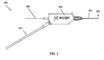
- FIG. 1is a side perspective view of one variation of a catheter device.
- FIG. 2Ashows the distal section of an exemplary catheter device.
- FIG. 2Bis a diagram of a distal section of an exemplary catheter device showing the alignment of markers thereon.
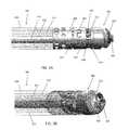
- FIGS. 3A-3Bshow various side perspective views of the distal end an exemplary catheter device.
- FIG. 3Cshows the distal end of the device of FIGS. 3A-3B , but with the collar removed.
- FIG. 3Dshows the distal end of the device of FIGS. 3A-3C , but with the collar and outer sheath removed.
- FIG. 3Eshows an embodiment of the distal end of an exemplary catheter device wherein the bushing includes a shoulder.
- FIG. 4shows an optical fiber wrapped around a driveshaft of an exemplary catheter device.
- FIGS. 5A-5Eshow a handle assembly or partial handle assembly for an exemplary catheter device.
- FIG. 6shows an exemplary OCT system.
- FIGS. 7A and 7Bshow screen captures of an exemplary catheter device including an OCT imaging system.
- FIG. 8shows the orientation of an OCT image relative to a fluoroscopy image from a catheter device.
- FIGS. 9A-9Cshow screen captures used to aid steering an exemplary catheter device.
- FIG. 10shows an exemplary diagram used to determine the amount of central masking required for an OCT image of an exemplary catheter device.
- FIGS. 11A-11Cillustrate one variation of an exemplary catheter having a rotating distal tip region (housing and wedges extendable from the housing) with the rotating wedges retracted into a rotating housing ( FIG. 11A ); with the rotating wedges extending from the rotating housing ( FIG. 11B ); and with the distal end region deflecting ( FIG. 11C ).
- FIGS. 12A and 12Bshow isometric views of one variation of a system for oscillating the distal end of a catheter, which may be used as part of a catheter device.
- FIG. 13Ashows an end perspective view of the oscillation system of FIGS. 12A and 12B ;
- FIG. 13B-13Dillustrate rotation of the camming mechanism and driveshaft of this system.
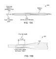
- FIG. 14Ashows cross-sections though a vessel with a catheter located in the true lumen (e.g., surrounded by both the adventitia and media);
- FIG. 14Bshows cross-sections through a vessel with a catheter located in the false lumen (e.g., between the adventitia and the media).
- FIG. 15Ashows one variation of an exemplary catheter.
- FIG. 15Bshows another variation of an exemplary catheter including an inflatable centering feature.
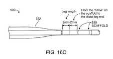
- FIG. 16Ashows the distal end of one variation of an exemplary catheter having an inflatable centering feature
- FIGS. 16B and 16Cshow enlarged views of the proximal and distal ends of the inflatable balloon region of the catheter of FIG. 16A , respectively.
- FIG. 17shows one variation of a handle region of the catheter of FIG. 16 .
- FIG. 18shows the catheter of FIGS. 16A-17 with the inflatable centering feature inflated.
- FIG. 19Ashows the distal end of the catheter of FIG. 18 fully deflated
- FIGS. 19B and 19Cshow enlarged views of the proximal and distal ends of the deflated balloon of FIG. 18 , respectively.
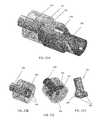
- FIG. 20Ashows an isometric view of closed/non-activated distal atherectomy device assembly.
- FIG. 20Bshows the device of FIG. 20A in the active/open configuration.
- FIG. 21illustrates the helical auger geometry of the atherectomy device shown in FIGS. 20A and 20B .
- FIGS. 22A-22Dshow a variation of a distal atherectomy system with an auger component.
- the catheters described hereintypically include one or more imaging sensors at the distal end that may be rotated independently of the elongate body of a catheter.
- An imaging sensormay include an optical coherence tomography (OCT) sensor.
- OCToptical coherence tomography
- the rotating distal endmay also include one or more tissue cutting or dissecting surfaces that may aid the catheter in advancing within occluded regions of a vessel.
- Examples of the types of catheters that are described herein in detailinclude: (1) guidewire support/placement catheters; (2) support/placement imaging catheters; (3) occlusion crossing catheters (4) occlusion crossing imaging catheters; (5) atherectomy catheters; and (6) atherectomy imaging catheters.
- Part Idescribes catheters, including occlusion crossing catheters, that may be used as guidewire placement and support catheters.
- Part Idescribes catheters configured for imaging from the inside of a vessel, such as an artery, during operation.
- Part IIdescribes atherectomy devices and methods of using them.
- the sections and subsections provided hereinare for convenience only; it should be understood that features included in one section or subsection may be included or excluded from devices described in any of the other sections and subsections.
- occlusion crossing catheterssuch as guidewire placement and/or support catheters (which may be referred to as “occlusion crossing catheters” for convenience) may be used to cross an occlusion or lesion. These catheters may be used to place a guidewire within an occluded lumen of a vessel. Any of the catheters described herein may include a guidewire lumen spanning all or most of the length of the device and a rotating and/or oscillating (clockwise and/or counterclockwise relative to the long axis of the catheter) distal tip, which may include one or more dissecting (e.g., cutting) surfaces. The rotatable distal tip region may be used to position a catheter through an occluded lumen of a vessel, including for treatment of chronic total occlusions.
- Imagingmay be forward-facing, lateral-facing, adjustable between forward-facing and lateral-facing, and/or rear-facing or angled between the forward and lateral facing. Any appropriate imaging modality may be used, but particularly those using one or more optical fibers, such as optical coherent tomography (“OCT”).
- OCToptical coherent tomography
- the catheters described hereincan be dimensioned to fit within vessels of the body, such as blood vessels.
- the catheterscan be configured to be placed within the peripheral blood vessels.
- the catheterscan have an outer diameter of less than 0.1 inch, such as less than 0.09 inches, such as less than or equal to 0.08 inches.
- a catheter devicein one embodiment, includes a distal tip that is rotatable and an onboard imaging system for visualizing the vessel as the device is positioned.
- the systemincludes an OCT imaging system for visualizing the structure and morphology of the vessel walls. The system can see a distance of up to 3 mm, such as up to 2 mm, into the depth of the vessel walls.
- a catheter (which may be used as a guidewire positioning catheter) 100includes an elongate flexible shaft 301 and a rotatable distal tip 305 having an imaging sensor, such as an OCT sensor, connected thereto.
- the shaft 301extends from a handle region 303 and terminates in the rotatable distal tip 305 .
- the device 100 in FIG. 1is not necessarily shown to scale, as the length of the shaft has been reduced to show the other features at a more appropriate scale.
- a guidewire 309can extend through the guidewire catheter device 100 , such as through a guidewire lumen in the shaft 301 .
- the guidewire 309may be held resident in the device 100 as it is positioned within a patient or it may be inserted after the distal end of the shaft 301 , or at least the distal tip 305 , has been positioned within the lumen of the vessel, such as past an occlusion or lesion.
- the guidewire lumencan be housed inside of a driveshaft (not shown in FIG. 1 ) configured to rotate the tip 305 .
- the driveshaftis a tubular shaft such that the driveshaft may surround the guidewire lumen.
- the driveshaftis a solid shaft which extends through the length of the catheter, and runs alongside (e.g., adjacent to) the guidewire lumen.
- the systemcan include an optical fiber (not shown in FIG. 1 ) that is fixed at one end to the distal tip 305 , but is otherwise free to move around, such as within an internal lumen between a lumen housing the guidewire 309 and an outer casing of the shaft 301 .
- Power and imaging lines 307(“cabling”) may extend from the handle region 303 to connect the optical fiber with a power source and a light source for the OCT system.
- the handle region 303can house the control mechanism for controlling the rotation of the distal tip (and OCT reflector/sensor at the end of the optical fiber).
- the control mechanismcontrols the direction of the distal tip as well as the number of revolutions before switching direction.
- the handle region 303can also control the rate of rotation.
- the rate of rotation, as well as the number of clockwise and/or counterclockwise rotationsmay be optimized to advance the distal end of the device though an otherwise occluded lumen of a vessel while generating a cross sectional image of the lumen, i.e., 360 degrees.
- the rate and number of rotationsmay also be optimized to prevent damage to the optical fiber used for the OCT imaging which is attached only at the distal end of the device such that the rest of the fiber can extend along the length of the shaft 301 can wrap, off-axis, around the internal lumen (e.g., guidewire lumen) of the catheter without breaking.
- the internal lumene.g., guidewire lumen
- the shaft 301can include a fixed jog 989 , or a J-shaped bend, near or just proximal to the distal tip 305 .
- the fixed jog 989can have an angle of 10 to 45 degrees, such as between 20 and 30 degrees.
- the jogis shapeable by the user prior to placing the catheter in the body lumen, i.e., the user can fix the jog 989 at the desired angle prior to use.
- the fixed jog 989can aid in steering the shaft 301 to the point of interest.
- the shaft 301can include an outer sheath 284 .
- the outer sheath 284can include a braided material, such as stainless steel, elgiloy, cobalt-chromium alloys, carbon fiber, or Kevlar.
- the braided materialcan improve the stiffness of the catheter to help navigate the catheter through vessel.
- the shaft 301can include a guidewire lumen 363 (see FIG. 3B ) extending within a driveshaft 421 (see FIGS. 3A-3D ) from the proximal end to the distal end of the catheter.
- the guidewire lumen 363can end in an opening in a distal tip 305 of the device.
- the guidewire lumen 363can thus be configured to pass a guidewire therethrough.
- the distal tip 305can include an imaging sensor, such as an OCT sensor 286 configured to capture images within a lumen.
- one variation of the distal end of the shaft 301can have a distal tip 305 that is roughly corkscrew or helically shaped.
- the distal tip 305can thus include spiral flutes, such as two spiral flutes.
- the distal tip 305rotates and does not extend or retract into a housing, i.e. remains exposed from the shaft 301 .
- the distal tip 305can be attached to a driveshaft 421 that rotates within the outer sheath 284 and can be configured to rotate in both the clockwise and counterclockwise directions.
- the distal tip 305can include a substantially smooth, curved outer surface 322 that presents an atraumatic tissue-contacting surface when rotated in one direction, i.e., the counterclockwise direction in FIGS. 3A-3D , and that further presents a sharp, tissue-cutting surface or edge 403 when rotated in the opposite direction, i.e. the clockwise direction in FIGS. 3A-3D .
- At least a portion of the tip 305can have a diameter that is substantially equal to or greater than the diameter of the shaft 301 . That is, the cutting edge 403 can be helical such that at the distal end, the diameter of the cutting geometry is reduced to the size of the guidewire lumen and gradually increases to the approximate outer diameter of the shaft 301 as it moves proximally. Further, the tip 305 can be configured such that it cuts only in the forward direction and not substantially in the lateral direction. That is, the cutting edge 403 can be substantially forward-facing.
- An OCT imaging sensor 286(including the distal end of the optical fiber 411 and the mirror 412 ) can be fixed to the rotatable distal tip 305 and rotate with it.
- the distal end of the optical fiber 411can be secured in a notch 344 formed in the rotatable distal tip 305 .
- An epoxy or other securing material that has a refractive index appropriately mismatched with the end of the optical fiber 411can hold the end of the optical fiber 411 in the notch 344 , as described in U.S. patent application Ser. No. 12/790,703, Publication No. US-2010-0305452-A1, incorporated by reference above.
- the imaging sensor 286can direct the optical beam for OCT imaging from the distal tip 305 of the catheter into the tissue.
- the imaging systemis oriented so that the mirror 412 directs the optical beam approximately or substantially perpendicular to the catheter axis. In some variations, this angle is different or is adjustable. For example, the orientation of the mirror 412 may be changed (including adjusted by the user) to change the direction of imaging and/or image more distally or proximally. As used here, substantially perpendicular may include plus or minus 10 degrees, plus or minus 5 degrees, or plus or minus 2 degrees, off of the 90 degree angle that is perpendicular from the elongate axis of the distal tip and/or catheter body.
- the sensor 286can be located close the distal end of the tip 305 , such as just proximal to the cutting edge 403 .
- the sensor 286can be located within 5 mm of the distal end of the tip 305 , such as less than 3 mm, such as approximately 2 mm.
- the resulting imagewill be a closer approximation of the exact tissue or material being passed by the distal end.
- the sensor 286may be directed laterally (e.g., to image the sides of the vessel in which the catheter is traveling), or angled forward or backward.
- the sensor 286can be located off of the central axis of the shaft 301 and close to the outer diameter of the tip 305 , such as within 0.05 inches, e.g. less than 0.3 inches, less than 0.02 inches, or less than or substantially equal to 0.01 inches of the outer diameter of the tip 305 .
- the depth that the OCT system can see into the tissuewill be greater, i.e., the amount of tissue lying within the OCT imaging range is increased.
- the rotating tip 305is held in a chassis 405 that is fixed relative to the shaft 301 , i.e., that does not rotate with the rotating tip 305 .
- the chassis 405is any structure within which the distal tip 305 can rotate and which secures the driveshaft 421 and/or the distal tip 305 to the end of the shaft 301 ; it may also be referred to as a housing.
- the outer sheath 284can be connected to the chassis 405 such that the outer sheath also remains stationary while the distal tip 305 rotates.
- the chassis 405can have one or more “window” regions through which the OCT imaging sensor 286 can view the tissue.
- the chassis 405can include three window regions 346 separated by spines 419 (which may be referred to as posts, struts, dividers, separators, etc.) arranged annularly around the chassis 405 .
- These spines 419may serve as reference markers as the imaging sensor 286 rotates, as discussed below.
- the spines 419may be separated from one another by different distances. For example, one of the windows may be larger than the other two, or smaller than the other two. This asymmetric sizing may provide a visual reference on the display of the OCT imaging.
- the spines 419can have a predetermined and fixed location relative to the jog 989 in the catheter.
- one of the spines 419can be aligned relative to the jog 989 . In one embodiment, shown in FIG.
- the second spine 419is aligned opposite to the jog 989 , i.e., such that the catheter points away from the second spine 419 (the inner curved portion of the jog 989 is opposite to the second spine 419 and the outer curved portion of the jog 989 is axially aligned with the second spine 419 ).
- This alignmentcan be used to help orient the device in a specific direction with respect to the image and/or vessel, as discussed further below.
- the distal tip 305can include a groove 392 at the proximal end to engage a bushing 394 (e.g., annular ring).
- the bushing 394can remain fixed with respect to the shaft 301 and may provide a lubricious surface to eliminate or reduce friction and fix the longitudinal position of the distal tip 305 .
- the bushing 394may be made of PEEK or other hard lubricous material.
- the groove 392may be crimped or clamped to the stationary chassis 405 , thereby allowing the rotatable distal tip 305 to have improved stability during rotation.
- the bushing 394includes a shoulder 445 .
- the shoulder 445can extend outward into the space between the distal edge of the chassis 405 and the distal tip 305 .
- the shoulder 445can be made of the same lubricous material as the rest of the bushing 394 .
- the shoulder 445prevents the distal edge of the chassis 405 from rubbing against the tip 305 and further reduces the friction of the system.
- the chassis 405may engage the groove 392 of the distal tip 305 directly, such as by one or more tabs 407 or locks that can be pushed in when the distal tip 905 is held within the chassis 405 to lock the bushing ring 394 and distal tip 305 in position.
- the chassis 405 or distal tip 305can be made from a lubricious material.
- the chassis 405can include one or more openings or ports 422 out of which a clearing fluid, such as saline or water, may be driven to help clear the pathway for imaging the walls of the vessel lumen as the device is operated.
- a clearing fluidsuch as saline or water
- Bloodincluding red blood cells and other blood components, may degrade the ability of the OCT imaging system from imaging other tissues because OCT may not readily “see” through blood.
- the cathetermay be configured to clear the blood from the region of interest, i.e., the region where the optical beam is emitted from the catheter for OCT imaging.
- the ports 422can thus be configured to emit a clearing fluid from the catheter to clear blood from the imaging sensor.
- the port 422is located directly adjacent to the imaging sensor and emits fluid to clear blood from the region where the optical beam is being emitted.
- the ports 422can be less than 2 mm from the imaging sensor, such as less than 1.5 mm.
- the pressure and amount of clearing fluid required to clear the blood from the region of interestcan be low. For example, less than 1 ml, such as less than 0.5 ml, e.g., less than 0.2 ml of clearing fluid can be required to clear the blood from the region of interest.
- the required pressuremay be nominal and the flow of saline or other clearing fluid may be minimal and still effectively clear blood from the imaging space, greatly improving the resolution of the vessel walls and increasing the depth of penetration.
- using small amounts of clearing fluidcan advantageously avoid problems associated with having too much fluid in a small space, such as separation of tissue (e.g., dissection).
- the shaft 301can be configured such that the clearing fluid enters at the proximal end of the catheter and is transported to the distal end by flowing in a space 472 between the outer sheath 284 and the driveshaft 421 .
- the clearing fluidmay be pressurized from the proximal end (e.g., using a syringe, etc.) so that it is pushed out of the opening 422 to clear blood from the OCT pathway.
- the OCT portion of the catheter device 100may be referred to as an off-axis imaging system because the management of the OCT optical fiber 411 is arranged asymmetrically, off-axis with reference to the long axis of the catheter.
- the fiber 411can be configured to extend freely within the shaft 301 in the space 472 between the driveshaft 421 and the outer sheath 284 except where it is attached at the distal end of the device, e.g., at the rotatable distal tip 305 . Accordingly, as shown in FIG. 4 , when the driveshaft 421 is rotated to rotate the distal tip 305 , the fiber 411 can wrap around the driveshaft 421 . This arrangement can advantageously enhance the flexibility, i.e., allow for movement of the catheter without fracturing the optical fiber 411 .
- both the rate of rotation and the number of rotationsmay be controlled to optimize performance, prevent the fiber 411 from binding within the shaft 301 , and prevent the fiber 411 from snapping due to excessive twisting or rotation.
- the distal tip 305may be configured to alternate its rotation from clockwise to counter clockwise.
- the driveshaft 421can be configured to rotate (with the distal tip 305 ) clockwise for a fixed number of rotations and to rotate counterclockwise for the same number of rotation before switching back to clockwise rotations and repeating the process.
- the number of rotations in the clockwise directioncan be substantially equivalent to the number of counter clockwise rotations in order to relieve any residual twisting.
- the deviceis configured to rotate the distal tip n rotations clockwise and n rotations counterclockwise, switching between clockwise and counterclockwise rotational direction after each n rotations.
- the number of rotations ncan be any number, including fractional, typically between 1 and 100; preferably it is between 1 and 10, depending on the length of the catheter and the amount of stress the fiber can withstand.
- the devicemay be configured to rotate approximately 6, 8.5, 10, 12.7, 15, etc. times clockwise, then counterclockwise the same number of rotations.
- the deviceis configured so that it doesn't continuously spin clockwise or counterclockwise, but has a limited number of rotations in either direction (e.g., less than 25 rotations, such as 10 rotations), after which it automatically switches to rotate the other direction.
- the transition between clockwise and counterclockwise rotationmay be performed automatically, which is described in more detail with reference to FIGS. 5A-5E , below.
- the rotationmay be driven by a motor or other driver (e.g., within the handle) or it may be manual.
- the rotationis automatic, and is driven at a constant speed that is typically between about 1 and 300 revolutions per minute (rpm); for example, the rotation rate may be about 10 rpm, 20 rpm, 30 rpm, 40 rpm, 50 rpm, 60 rpm, etc.
- the distal tipis rotated between about 1 and about 100 rpm, e.g., between about 1 and 80 rpm, such as between about 30 and 60 rpm.
- the rate and the consistency of rotationmay be optimized for penetration through the occlusion within the vessel, for image stability, and also to produce relatively streak-free imaging using the OCT.
- the rate of rotationmay be limited to an upper limit speed that is held relatively constant.
- the rate of rotationmay be sufficiently low (e.g., less than 150 or 100 or 50 rpm) so that the distal head rotates but does not ‘drill’ through the tissue, including one or more occlusions.
- the usercan control the rate of rotation, such as by setting the motor to rotate at a particular speed.
- the handle 303 of the devicecan be configured to control rotation and advancement of the shaft 301 .
- the handle 303can include a switch 562 configured to turn the system on or off (i.e. to start the rotation of the distal tip and/or the imaging system).
- the handlecan be covered by a housing 501 which may be configured to conform to a hand or may be configured to lock into a holder (e.g., for connection to a positioning arm, a bed or gurney, etc.).
- a drive systemincluding a motor 503 and drive gears 515 , 516 , 517 , may drive the driveshaft 421 to rotate the distal tip 305 of the device and/or the OCT imaging system relative to the shaft 301 .
- the drive systemis controlled or regulated by a toggling/directional control subsystem for switching the direction of rotation of the driveshaft between the clockwise and counterclockwise direction for a predetermined number of rotations (e.g., 10).
- a mechanical directional controlcan be configured to switch the direction of rotation between clockwise and counterclockwise when the predetermined number of rotations have been completed.
- the directional controlincludes a threaded track (or screw) 511 which rotates to drive a nut 513 in linear motion; rotation of the threaded track by the motor 503 results in linear motion of the nut along the rotating (but longitudinally fixed) threaded track 511 .
- the nut 513moves linearly in a first linear direction (e.g., forward) until it hits one arm of a U-shaped toggle switch 516 , driving the U-shaped toggle switch in the first linear direction and flipping a switch 523 (visible in FIG. 5D ) to change the direction of the motor 503 to a second rotational direction (e.g., counterclockwise), and causing the nut to move linearly in a second linear direction (e.g., backward) until it hits the opposite side of the U-shape toggle switch 516 , triggering the switch to again change the direction of rotation back to the first rotational direction (e.g., clockwise).
- a first linear directione.g., forward
- a second rotational directione.g., counterclockwise
- a second linear directione.g., backward
- the motor 503may be configured to rotate the driveshaft 421 in either direction at a constant speed.
- the systemmay also include additional elements (e.g., signal conditioners, electrical control elements, etc.) to regulate the motor as it switches direction.
- the number of threads and/or length of the threaded track (screw) 511may determine the number of rotations that are made by the system between changes in rotational direction. For example, the number of rotations may be adjusted by changing the width of the U-shaped toggle 514 (e.g., the spacing between the arms). Lengthening the arms (or increasing the pitch of the screw) would increase the number of rotational turns between changes in direction (n). The toggle may therefore slide from side-to-side in order to switch the direction of the motor.
- the length of the nut 513can also determine the number of rotations that are made by the system between changes in rotational direction, i.e., the longer the nut, the fewer the number of rotations before switching direction.
- the motor 503is rotated in a constant direction, and the switch between clockwise and counterclockwise is achieved by switching between gearing systems, engaging and disengaging an additional gear, or using gears that mechanically change the direction that the driveshaft is driven.
- the drive systemincludes the motor and three gears that engage each other to drive the driveshaft in rotation.
- the motor 503rotates a first gear 517 , which is engaged with a second gear 516 (shown in this example as a 1:1 gearing, although any other gear ratio may be used, as appropriate).
- a third gear 515engages with the second gear 516 .
- the third gearmay drive or regulate an encoder 507 for encoding the rotational motion. This encoded information may in turn be used by the drive system, providing feedback to the drive system, or may be provided to the imaging system.
- the cabling 307can include both a fluid flush line 552 configured to be attached to a fluid source and an optical fiber 411 configured to be connected to the OCT system.
- the flush line 552 and the fiber 411can both run through the handle 303 .
- the fiber 411 and the flush line 552can be bonded at a bonding point 566 in the handle 303 , creating a seal to prevent fluid from leaking into the handle.
- the flush line 552can end at the bonding point 566 , allowing the fluid to exit the flush line and continue down the shaft 301 in the space 572 between the outer sheath 284 and the driveshaft 421 .
- the fiber 411can extend through the bonding point 566 and wrap around the driveshaft 421 in the space 572 . As shown, because the fiber 411 is configured to wrap around the guidewire lumen, a separate fiber management system is not necessary. In some embodiments, a protective coating 564 can surround the optical fiber until distal of the bonding point 566 .
- the fiber 411can be connected at the proximal end to a common-path OCT system 600 .
- the common-path OCT system 600includes a light source 102 , such as a swept frequency laser.
- the light sourcecould be a broadband light source such as a super-luminescent diode (to conduct Time Domain OCT or Spectral Domain OCT using an optical spectrometer).
- the optical fiber 411transfers radiation from the light source 102 to the target 114 .
- the optical fiber 411is in optical contact with an interface medium 106 , i.e. the light exiting the optical fiber and entering the interface medium sees only one interface.
- an interface medium 106i.e. the light exiting the optical fiber and entering the interface medium sees only one interface.
- the end of the optical fiberis embedded in the interface medium 106 .
- the interface medium 106can be, for example, a glue or epoxy.
- the index of refraction of the interface medium 106is different than the index of refraction of the core of the optical fiber 411 . This creates a Fresnel reflection, in which part of the light exits the core, and part of the light is reflected back. Some of the light beam that exits the optical fiber 411 will encounter the target 114 and be reflected or scattered by the target 114 . Some of this reflected or scattered light will, in turn, reenter the tip of the optical fiber 411 and travel back down the fiber 411 in the opposite direction.
- a Faraday isolation device 112such as a Faraday Effect optical circulator, can be used to separate the paths of the outgoing light source signal and the target and reference signals returning from the distal end of the fiber.
- the reflected or scattered target light and the Fresnel-reflected reference light from the fiber facecan travel back to a detector 110 located at the proximal end of the optical fiber 411 .
- the reflected or scattered target light in the OCT system 600travels a longer distance than the Fresnel reflected reference light
- the reflected or scattered target lightcan be displaced by frequency, phase and or time with respect to the reference beam.
- the light from the targetwill be displaced in frequency.
- the difference in displacement in phase, time or frequency between the reflected or scattered target light and the reference lightcan be used to derive the path length difference between the end of the optical fiber tip and the light reflecting or light scattering region of the target.
- the displacementis encoded as a beat frequency heterodyned on the carrier reference beam.
- the light source 102can operate at a wavelength within the biological window where both hemoglobin and water do not strongly absorb the light, i.e. between 800 nm and 1.4 ⁇ m.
- the light source 102can operate at a center wavelength of between about 1300 nm and 1400 nm, such as about 1310 nm to 1340 nm.
- the optical fiber 411can be a single mode optical fiber for the ranges of wavelengths provided by the light source 102 .
- FIGS. 7A and 7Bare exemplary screen captures of an imaging output from the system described herein.
- the displayed image 800is divided into three components.
- On the rightis a fluoroscopic image 810 showing the distal end 805 of the catheter within a vessel 814 . Contrast has been inserted into the vessel 814 to show the extent of the vessel 814 and any occluded regions.
- an OCT image 820On the left is an OCT image 820 .
- the distal tip of the catheterrotates at approximately 30 rpm, and the OCT system provides a continuous set of images as the catheter rotates within the vessel.
- the imagesare combined into a continuously updated OCT image 820 that corresponds to the inside of the lumen in which the catheter is inserted. That is, the OCT image 820 is an image trace of the interior of the vessel just proximal to the distal tip as it rotates.
- the line 822(extending to almost 12 o'clock in the figure) indicates the current direction of the OCT laser beam as it is rotating.
- the circle 824 in the middle of the image 820represents the diameter of the catheter, and thus the area surrounding the circle 824 indicates the vessel.
- the OCT imagingcan extend more than 1 mm from the imaging sensor, such as approximately 2 mm or approximately 3 mm and thus will extend into the walls of the vessel (particularly in the closer region of the vessel) so that the different layers 826 of the vessel may be imaged.
- the three striped rays 744(extending at approximately 2 o'clock, between 7 and 8 o'clock, and approximately 11 o'clock) indicate the location of the three spines of the catheter and thus may act as directional markers, indicating the orientation of the distal end of the catheter within the body.
- the usermay also be able to determine relative orientation of the OCT image (relative to the patient's body orientation) using these striped rays 744 .
- a waterfall view 830 of the OCT imageAs it circles the radius of the body.
- This waterfall image 830may be particularly useful in some applications of the system, for example, indicating the relative longitudinal position of a feature (e.g., layered structures, occlusions, branching region, etc.) as the device is moved longitudinally within the vessel.
- the waterfall view 830typically includes a time axis (the x-axis) while the y-axis shows the image from the OCT sensor.
- the waterfall view 830may provide an indication of when the catheter has crossed an occlusion.
- the waterfall view 830may show the patient's heartbeat when the walls of the vessel move relative to the heartbeat.
- the waterfall view 830may show the walls of the vessel moving with the heartbeat.
- the distal tipis within an occlusion the wall of the vessel
- the waterfall viewwill not show movement of the walls since the occlusion material typically prevents the movement of the walls due to the heartbeat, while in healthy vessels the heartbeat is apparent.
- this effectmay be automated to provide an indication of when the device is within or has crossed an occlusion.
- crossing the boundary of a total occlusionis not well defined and may result in inadvertently dissecting the vessel.
- the vessel wallmay move; if the catheter tip is not in the true lumen all or part of the vessel wall will not move.
- this movement of the wall during heartbeatmay reflect the position within the true versus false lumen.
- FIG. 7Bshows another screen capture from the same procedure shown in FIG. 7A .
- the distal tip 305is further within the vessel 814 than in FIG. 7B .
- the OCT image 820shows a branch 818 of the vessel extending from the vessel in the 2 o'clock position.
- the shaft 301can include a fluoroscopy marker 702 (also shown in FIG. 2B and FIG. 4 ) that provides varying contrast in a fluoroscopy image depending on its radial orientation.
- the markermay be a radiopaque band with one or more asymmetric features such as a “C”, “T”, or dog bone shape that can be used to radially orient the shaft because the fluoroscopic image of the marker will change depending on its orientation.
- the fluoroscopy marker 702can have a fixed location relative to the spines 419 and/or the jog 989 .
- the fluoroscopy marker 702can be aligned opposite to the jog 989 and/or axially aligned with the second spine 419 described above.
- the fluoroscopy marker 702can be used to align a fluoroscopy image 710 with an OCT image 720 during use of the catheter.
- the shaft 301can be rotated slightly such that the marker 702 is aligned to a particular side of the screen, such as at the 9 o'clock position.
- the up/down position of the catheteri.e. whether the catheter is pointed down, as shown in FIG. 7 , or pointed up
- the OCT imagecan then be oriented such that striped ray 744 from the middle marker (the second spine 419 described above) of the shaft 301 is also at the 9 o'clock position in the OCT image 720 .
- Fluorosyncingcan be performed using manual input from the user, such as information regarding the up/down position and the rotational position, or can be performed automatically.
- the softwaremay draw the OCT image 720 either in a clockwise or counterclockwise direction (depending on the up/down orientation of the catheter in the fluoroscopy image 710 ) and will rotate the image 90°, 180°, or 270° (depending on the rotational position of the catheter in the fluoroscopy image 710 ).
- the absolute and relative position and orientation of the catheter within the patient's bodymay be determined.
- the markers on the chassis/imaging systemvisible in the OCT system) may therefore provide sufficient orientation markers such that the fluoroscopic imaging may be reduced.
- the displayed imagescan be used, in combination with steering mechanisms such as the OCT markers, the fluoroscopy marker, and the fixed jog of the device, to steer the catheter and rotatable tip to the desired location.
- the OCT image 920shows healthy tissue 956 in the form of a layered structure and non-healthy tissue 958 in the form of a nonlayered structure.
- the cat ears 962 in the imageshow a region between the healthy and unhealthy tissue caused by a slight expansion of the vessel around the catheter at that location. Accordingly, during a CTO procedure, one goal may be to steer the catheter towards the unhealthy tissue. Because the middle spine 419 is aligned opposite to the jog 989 (as shown in FIG.
- the ray 744 corresponding to the middle spine 419can be oriented opposite to the non-healthy tissue 958 to steer the catheter in the correct direction.
- FIG. 9Bshows the catheter deflected toward the layered, healthy tissue.
- FIG. 9Cshows the catheter rotated such that it is deflected toward the unhealthy, non-layered structure.
- the systemmay be configured to allow the orientation of the catheter to be rotated into the correct position using the fixed directional markers from the chassis that are visualized by the OCT.
- the distal end of the devicemay be steerable and may be steered while still rotating the distal end of the device.
- Additional steering membersmay also be included, such as a selective stiffening member, which may be withdrawn/inserted to help steer the device, and/or one or more tendon members to bend/extend the device for steering.
- Image correctioncan be performed on the resulting OCT images in order to mask out unwanted or unnecessary portions of the image.
- the fiber 411can be configured such that it ends within the shaft 301 .
- the fiber 411will image the distance c 1 between the fiber 411 distal end and the mirror 412 as well as the axial distance c 2 between the mirror 412 and the outer diameter of the shaft 301 .
- the resulting imagewould therefore include portions that correspond to the interior of the shaft. Accordingly, image processing can be performed such that distance c 1 , c 2 , or c 1 +c 2 is masked out in the displayed image.
- c 1 and c 2are masked out, only the area c 3 would show up on the image (where the total imaging distance or capability of the fiber is equal to c 1 +c 2 +c 3 ).
- up to 100 pixelscan be masked out, such as between 20 and 60 pixels, for example approximately 40 pixels.
- the imagecan be corrected to account for lag of the optical fiber in the amount of rotation at the handle vs. at the distal end of the catheter.
- Images for lag correctioncan be captured automatically.
- imagescan be exported and stored, for example in a movie format.
- the imagescan optionally viewed in adjustable grayscale. Further, the speed of the waterfall view can be adjusted.
- offset or “ghost” imagemay be overlaid atop the OCT to indicate the difference between the predicted and actual rotational orientation of the catheter.
- a manually rotatable devicemay be used with an adjunctive device providing a motorized movement of the distal tip.
- the handle portion of the devicemay set and be secured within a housing that includes a motor and gearing to automatically rotate the distal tip at a predetermined or adjustable speed.
- this motorized accessory devicemay adapt an otherwise manual device to automatically rotate.
- cathetersare possible that include one or more of the features described above.
- the rotatable distal tipincludes a fixed or rotatable housing from which dissection elements may extend or retract.
- An imaging elementsuch as an OCT imaging element, may be included in this embodiment as well.
- wedges 49may be extended from a rotatable distal tip 50 .
- FIG. 11Athe device is shown with the wedges retracted into the rotatable distal tip 50 .
- FIG. 11Bthe wedges 49 have been extended from the housing 46 .
- the distal end of the devicecan be shared and is shown deflecting upwards (steering in one plane) in FIG. 11C while the wedges are extended from the housing.
- Both the distal tip and the wedgescan be configured to rotate.
- the wedges 49(which may be sharp blades or may be blunt) can be extended from the distal housing and locked in any position (extended, partially extended or retracted) and rotated clockwise and/or counterclockwise while locked in a retracted, extended or partially extended position.
- the wedgesmay be fully or partially retracted into a distal housing.
- the extension of the wedge from the distal housingmay be limited.
- the wedgesmay be prevented from extending fully out of the distal housing, thereby preventing material (such as a plaque or tissue) from getting caught between the wedges and the housing.
- the wedges at the distal endmay be referred to as a blade or blades, even though they may be substantially blunt.
- the wedgesare configured so that they are forward-cutting, but not side-cutting. This means that they may include a forward-facing cutting edge, and the more lateral edges may be blunted or less sharp.
- the rotating distal tipincludes only a single wedge, rather than multiple wedges.
- the wedge (blade)may be helically arranged at the distal tip.
- the rotating distal endcomprises two or more wedges that are radially separated around the tip region (e.g., spaced equally apart radially). It may be advantageous to have three or more wedges spaced around the tip, which may improve centering of the device, as described herein.
- the distal tip of the deviceis rotated through multiple complete rotations (both clockwise and counterclockwise) to move the distal tip and/or any attached imaging sensor in rotation around the elongate longitudinal axis of the device.
- the distal tip of the devicemay be rotated through partial rotations. This is illustrated in FIGS. 12A-13D .
- a driveshaftrotates continuously in one direction, e.g., clockwise, but this one-directional rotation is translated at the distal end of the device into oscillating motion.
- FIG. 12Ashows a partially transparent view of one variation of an oscillatory motion system for rotating the distal end portion of a catheter back and forth (clockwise and counterclockwise) though a partial rotation, such as less than 360 degrees, e.g., less than 180 degree, etc.
- the systemis shown connected to an oscillation/rotating element 801 to which the imaging sensor, including a mirror 811 and the distal end of an optical fiber 813 for the exemplary OCT system, are connected.
- oscillation of the oscillation/rotating element 801moves the OCT sensor to image an angular view of the field of view.
- the oscillation/rotating element 801may be moveably housed within an outer housing 802 which may remain “fixed” relative to the inner oscillation/rotating element 801 .
- the outer housing 802may be connected to the rest of the catheter. In some variations, this catheter is strictly configured for OCT imaging and is not configured for atherectomy or for guidewire positioning.
- FIG. 12Bshows the device of FIG. 12A with the outer housing 802 removed.
- the oscillation/rotating element 801includes a C-shaped end region into which a camming member 805 that is attached to the rotating/rotatable driveshaft 803 is housed.
- the camming member 805 in this exampleis a cylindrical member to which the driveshaft 803 is eccentrically connected, so that the center of the longitudinal axis of the driveshaft 803 is off-axis for the center of the longitudinal axis of the camming member 805 .
- FIG. 13Ashows the camming member 805 and attached driveshaft 803 within the C-shaped cut-out of the oscillation/rotating element 801 .
- any of the catheters described hereinmay be used to treat peripheral vascular disease.
- the cathetersmay be used to place one or more guidewires across an occlusion, so that the occlusion may be imaged, removed, and/or displaced.
- the devices described hereinare centering or self-centering within the lumen of the vessel.
- the vessel 441(shown in cross-section on the left a transverse section on the right of each figure) includes the media 442 (e.g., tunica media) surrounded by adventitia 443 (e.g., tunica adventitia).
- the devices 400remain centered within the “true” lumen 445 (the center) of the vessel 441 as shown in FIG. 14A , rather than a “false” lumen 446 , i.e., the region between the adventitia 443 and media 442 as shown in FIG. 14B .
- the catheter devicedoes end up in the sub-intimal plane (e.g., false lumen 446 ), as illustrated in FIG. 14B , the device may reside between the media 442 on one side and the adventitia 443 on the other.
- the devicesmay be configured for both passive centering (self-centering) and active centering (including a centering mechanism).
- the devices described hereinare self-centering and are thus configured to help maintain the catheter (e.g., the tip of the catheter) within the true lumen.
- the manually or automatically rotatable distal end of the cathetermay guide the catheter in the true lumen, especially when the reaching the distal cap of a lesion.
- the tipmay be sufficiently blunt to passive self-center within the lumen of a vessel.
- the devicedoes end up within the “false lumen,” it can be configured to self-center back into the true lumen.
- adventitiatypically prevents the tip from engaging and tearing the tissue.
- the rotating tipit is easy for the rotating tip to engage with the media if it is presented in the front of the device, which may include the tissue-cutting surface(s).
- the rotating tipmay selectively dissect its way through the media and not through adventitia. Once the device dissects its way through the medial, it returns to the true lumen.
- centeringself-centering of the catheter may result from the rotation of the distal end for the dimensions of the devices illustrated herein, one or more additional centering features may also be used to help the device to stay in true lumen of the blood vessel.
- the cathetermay be configured for use with one or more centering features to help prevent the distal tip from leaving the true lumen.
- the centering featuremay project from the distal tip, the lateral sides of the distal tip, or the lateral sides of the distal end region, e.g., proximal to the distal tip.
- the centering featureis a balloon that expands (or is expandable, inflatable, or otherwise extendable from the lateral sides of the distal end region of the device) to keep the distal tip centered in the lumen.
- the devicemay also be deflectable or steerable at the distal tip region, as previously described, and/or may include one or more sensors (e.g., OCT imaging as described above), to help detect when the tip is approaching or has passed into the false lumen or otherwise left the true lumen.
- FIG. 15Aillustrates one variation of a catheter (as described in patent application U.S. Ser. No. 12/689,748, previously incorporated by reference) which may have a rotating distal tip region.
- FIG. 15Bshows a catheter 500 , similar to the catheter of FIG. 15A , but including a balloon 522 located proximal to the rotating distal tip.
- the centering mechanismcould apply to any of the catheter configurations described herein.
- the balloonmay cover or extend over the rotating distal tip region.
- the distal end regionmay include a balloon 522 that is collapsed around the outer diameter of the catheter shaft 103 , but may be inflated and expanded against the walls of the vessel. In addition to centering the distal end of the catheter shaft 103 , expanding the balloon 522 may also expand the opening or passageway through the vessel. This may, in turn, improve treatment outcomes with the device, perhaps by loosening or preparing the atheroma (or other occlusion) for removal or displacement.
- the proximal region of the catheter shaft 103includes a port 524 , for example a y-type connector, for inflation fluid, that may be use to inflate and deflate the balloon 522 . Any appropriate inflation fluid may be used, including water, saline, lubricant, dye, or some combination of these.
- the catheter 500is fabricated similarly to the catheters described previously, i.e., to include an inner lumen for passage of a guidewire, surrounded by a driveshaft for rotating/oscillating the distal tip, and again surrounded by an outer diameter jacket (e.g., of a flexible, braided stainless steel, polymer, etc.).
- an additional tube 533 to form the inflation lumen 535e.g., a 0.011′′ ID polyimide tube
- a mandrel 539e.g., a 0.009′′ stainless steel mandrel
- a balloon 522may be attached near the distal end (e.g., proximal to the distal end of the catheter 500 , as illustrated in FIG. 15B , and also FIGS. 16A-16C .
- the balloon 522can have a nominal dimension of approximately 10 cm in length and a diameter of 5 mm (expanded).
- the balloon 522has two rounded shoulder regions, one at the proximal end and one at the distal end; in some variations one or both ends may be tapered. In FIG.
- the inflation lumenends between the proximal and distal end of the balloon, e.g., near the center of the balloon, and terminates in a skived opening to allow entry/exit of inflation material.
- the balloon 522has a slightly smaller diameter at the proximal end compared to the distal end to compensate for the missing inflation lumen at the distal end; thus, the overall outer diameter of the catheter 522 may be remain relatively constant.
- the balloon 522may be fused to the outer portion of the distal end of the catheter, as shown in FIGS. 16A-C .
- a short length of PEBAX tubingmay be added to the shaft at the locations where the distal and proximal ends (legs) of the balloon will be located. These PEBAX lengths may be used to ensure that enough material seals and fuses the balloon to the outer shaft.
- FIGS. 16B and Cshow the fused proximal (“rear leg”) and distal (“front leg”) regions of the balloon.
- the inflation lumen 535(polyimide tube) is skived at the distal end to correspond to a location of the distal inflation/deflation hole approximately midway along the length of the balloon 522 .
- the balloon 522may be folded, sealed and/or heat set (e.g., to maintain the small delivery diameter, etc.).
- the balloon 522may be pleated, folded and heat set.
- FIG. 17shows one variation of the handle region 725 of a catheter 500 including a balloon-type centering feature.
- the proximal end of the deviceincludes a Y-arm with an inflation/deflation port or lumen 535 , and sealed in position, to prevent leakage.
- a separate inflation lumenis not included, but all or a portion of the region between the outer sleeve and the inner catheter (e.g., the central or offset guidewire lumen) is used as the inflation lumen connecting the inflation port to the balloon.
- the dimensions of the entire catheter, including the balloon and distal end regionmay be adjusted.
- the dimensions (un-inflated)are approximately: proximal shaft has a diameter between about 0.074 inches and 0.084 inches; the mid-shaft region has a diameter between about 0.074 inches and 0.079 inches; the proximal balloon leg has a diameter between about 0.085 inches and 0.094 inches; the distal balloon leg has a diameter between about 0.079 inches and 0.085 inches; and the mid region of the balloon over the inflation lumen has a diameter between about 0.077 inches and 0.085 inches.
- the double wall thickness of the balloonis approximately 0.0045 inches, and the catheter has a length from the distal end of the proximal assembly to the distal tip of the device of 111 cm, while the length from the distal end of the Y-arm to the distal tip of the device is approximately 91 cm.
- the balloonWhen inflated to 6 atm pressure, the balloon has a proximal diameter of about 0.218 inches, a mid-diameter of approximately 0.211 inches, and a distal diameter of approximately 0.210 inches (at 10 atm in this example, the proximal diameter was about 0.222 inches, the mid-diameter was approximately 0.216 inches, and the distal diameter was approximately 0.215 inches.
- FIG. 18shows one example of the catheter 500 with a balloon 522 inflated to approximately 6 atm with water. Deflation may be achieved using the inflation/deflation lumen 535 . In one example, complete deflation took approximately 3 min. However, this may be faster or may be performed slower by adjusting the annular size of the inflation lumen or the viscosity of the inflation fluid. The balloon 522 was deflated until little or no residual inflation fluid was present in the balloon.
- FIGS. 19A-Cillustrate the balloon 522 of FIG. 18 after deflation and removal of the inflation fluid.
- the balloon 522has not been folded and/or pleated (or heat-set into this folded/pleated configuration), so the balloon collapses as shown.
- the outer diameter of the cathetermay be kept small in the deflated configuration.
- centering featuremay be used as well, not limited to the annular/toroidal balloon described above.
- one or more armsmay extend from the outer shaft of the device and apply lateral force against the walls of the vessel to center it within the lumen.
- a coil located near the distal end and coiling around the distal end regionmay be expanded to extend loops outward and center the device.
- Any appropriate material, including shape memory materials (e.g., nickel titanium)may be used, and the centering feature may be configured to be atraumatic when contacting the vessel lumen (e.g., having rounded or flat, large-diameter tissue-contacting surfaces, etc.).
- the guidewire positioning devices described hereinmay be configured as single-use, over-the-wire, devices.
- the devicemay be compatible other guidewires of standard sizes used in minimally invasive procedures.
- the outer diameter of the elongate device (including the distal end region)may fit within a 7 F sheath.
- the devicesmay be used with any appropriate guidewire, including steerable guidewires.
- the guidewiremay be a 0.035′′ guidewire.
- These devicesmay generally be described as “steering” a guidewire, although they may be used with a guidewire within the catheter, or the guidewire may be positioned within the device after the catheter has been positioned.
- these devicesmay provide support and guidance for positioning a guidewire across an occlusion.
- the devicesmay support probing and exchange of an assortment of guidewires, by traversing an occlusion in a vessel.
- the cathetersare inserted ahead of the guidewire (or with the guidewire retracted within the catheter) to provide a safe pathway thorough the occluded vessel, and thereby reduce or eliminate unnecessary damage to the vessel.
- the devices described hereinmay be used to deliver contrast.
- the internal lumenwhich may be used by the guidewire and/or the outer lumen may also be used for local dye or fluoroscopic contrast injections without removing the device from the vessel.
- the rotating/oscillating distal tipallows the device to be passed through an occlusion such as a plaque occluding a blood vessel (or artery) without requiring removal of the plaque.
- the devicemay be used to bluntly form a pathway through a plaque using the retractable/extendable rotating wedges at the distal tip, or simply using the rotating distal tip alone.
- the cutting edges at the distal tipmay also allow for helical and blunt micro-dissection. It is important to note that the catheter may be used without substantially dissecting or cutting the tissue, and that the distal tip is not necessarily intended (and may not) remove tissue, but merely form a passage through an occluded vessel. Once in position, the guidewire may be used to insert other devices, including atherectomy catheters.
- the cutting edges at the distal tipare sharp (e.g., cutting or knife-edged), while in other variations the cutting edges are substantially blunt.
- the cutting edgesare typically curved around or along the longitudinal axis of the distal tip.
- the cutting edgemay extend helically around the distal tip end of the device.
- the catheters described hereinmay be used (e.g., inserted) in to the body in a 7 F guide sheath for placement into the body.
- the elongate catheteris flexible, and the outer surface(s) may be coated so that the catheter can be readily inserted into a lumen of a sheath, catheter, or directly into a body lumen.
- the elongate outer sheathis typically tubular, and may be coated (either or both inner and outer diameter surfaces) with a protective cover.
- the elongate outer sheathmay be referred to as a shaft (e.g., catheter shaft), and may be coated with a lubricious material or may be formed of a smooth and/or lubricious material.
- the distal tip of the catheteris retractable into an expanded approximately toroidal-shaped distal balloon that is expanded proximal to the distal tip. This variation may allow re-centering or re-orientation of the catheter.
- the distal end of the catheters described hereinmay be steerable.
- the distal end regionmay be steerable in any appropriate manner.
- the distal end regionmay be steerable by defecting in one direction (e.g., ‘down’) or in more than one direction (e.g., down/up, right/left, etc.).
- the degree of deflectionmay also be controlled.
- the tipmay be deflected a maximum of 10 degrees, 15 degrees, 20 degrees, 25 degrees, 30 degrees, 45 degrees, 60 degrees, 90 degrees, or any angle there between.
- the distal end region of the deviceis pre-biased to be straight.
- the straight configuration of the distal tipmay be restored once the deflection (controlled at the proximal end) is restored to the straight configuration.
- the distal end of the deviceis flexible.
- the end regionmay include the tip (e.g., the rotating tip) or it may include the region immediately proximal to the tip.
- the “tip region”may refer to the rotatable tip region at the distal end.
- the deflectionmay be performed by any appropriate method, including a pullwire coupled to a hinged distal region, a prebiased curve which can be released (e.g., by a pullwire, etc.), etc.
- the deflectable/steerable distal end region(which may be referred to as the “steerable tip”) may allow the catheter to re-enter the true lumen of the vessel if it becomes subintimal (e.g., if it extends into the fascia or region around the vessel).
- the distal region of the catheteris prebent, e.g., includes a jog.
- the catheterincludes a bendable distal end. Steering these catheters may be aided by visualization and may include rotating the length of the catheter body, which may be guided by imaging. Rotation or turning of the catheter body may be used to orient the distal tip region because of the bend in the catheter, in both fixed bend and bendable catheters.
- proximal handlemay act as an interface with the operator, and may include one or more controls.
- the handle regionmay also include connections to power (e.g., in automatic rotating/oscillating variations), imaging (e.g., connection to imaging source and processing), or the like.
- the devices described hereinmay be any appropriate length, but relatively short length catheters may be particularly useful.
- the devicemay be approximately 100 cm, allowing the device to reach any occlusion down to the popliteal and ease physician handling outside the body.
- the deviceis between about 50 and 150 cm, between about 70 and 120 cm, etc.
- the distal tipmay be driven by an elongate driveshaft (or “torque shaft”) that extends the length of the device.
- This driveshaftis typically robust, allowing increased torque precision and manipulation during the operation.
- the torque shaftmay be made of a braided stainless steel material having a hollow lumen (forming or surrounding a central, e.g., guidewire, lumen of the device).
- Rotation of the driveshafttypically drives the distal tip rotation.
- the driveshaftis typically flexible and connects to the rotational control at the proximal end (e.g., handle).
- the distal tip, including the wedges and housingmay rotate both clockwise and counterclockwise.
- the handle region at the proximal end of the devicemay also be adapted for handheld use.
- the controls at the handle regionmay be adapted so that the device may be manipulated by a single hand.
- the handle regionmay also include one or more indicators or displays for displaying the status of the distal end of the device.
- the handlemay include an indicator indicating the extent to which the wedges are extended from the distal tip.
- the indicatormay be a dial, slider, or the like.
- the indicatormay be marked or unmarked.
- the proximal handlemay be otherwise configured to be handheld.
- the controlsmay be clustered or located at one end of the handle with a gripper region at the other end.
- the controlsmay be clustered at the proximal portion of the handle (allowing the distal portion of the handle to be gripped in the palm of the hand, and manipulated by the thumb and forefinger of the right.
- the elongate outer sheath of the catheteris flexible, and may be coated so that it can be readily inserted into a lumen of a sheath, catheter, or directly into a body lumen.
- the elongate outer sheath of the cathetermay be formed of a braided stainless steel, a polymer, or the like.
- the elongate outer sheathis typically tubular, and may be coated (either or both inner and outer diameter) with a protective cover.
- the elongate outer sheathmay be referred to as a shaft (e.g., catheter shaft), and may be coated with a lubricious material or may be formed of a smooth and/or lubricious material.
- the forward cutting bladesmay prevent cutting on the sides/walls of the lumen.
- This configurationmay also help with self-centering, as mentioned.
- the devicemay be configured so that the diameter of the blade (e.g., wedge) region is the same as the diameter of the rest of the catheter.
- the diameter of the distal end having the rotatable wedgeis maximized so that the blades are the same crossing profile as the rest of the catheter, which may allow for optimal engagement within the occlusion in the vessel.
- the guidewire lumen described hereinis not central, but is offset along all or a portion of the length of the device.
- the lumen(or a separate lumen) may also be used to pass a material such as a contrast dye, saline, an imaging device, etc.
- An outer lumenmay surround the inner (guidewire) lumen, and may enclose this space to form a separate lumen in which one or more additional lumens (e.g., inflation lumen in variations including a balloon or expandable feature) may be included; a driveshaft for rotating or controlling rotation of the distal tip may also be included.
- the proximal end of the devicetypically includes a handle region that may be used to control the distal end.
- the devicemay include a rotation control, a wedge articulation control and/or a steering control.
- these controlsmay be combined into one or more controls or these functions may be distributed or divided between different controls. Any appropriate control may be used, including slides, knobs, dials, buttons, levers, switches, etc.
- the controlsmay be automated or computer-controlled.
- a drivere.g., motor, mechanical driver, etc.
- rotation of the distal tip regionmay be driven by a motor, and may be geared or otherwise controlled. The rotation may be manually or automatically controlled.
- an atherectomy catheter(which may be used after placement of a guidewire as described above) is illustrated in FIGS. 20A-22D and described below.
- an atherectomy cathetermay access the vasculature using conventional catheterization techniques employing sheath and/or guiding catheter access and tracking over a positioned guidewire.
- the devicemay track through the vasculature to the target lesion.
- a fibere.g., a Single Mode fiber
- imaginge.g., OCT imaging
- the devicemay be rotationally oriented toward the diseased sector of the artery, and activated using proximal physician controls to preferentially expose the cutting edge to the diseased tissue.
- a circular cutterwill begin rotational movement at approximately 10 to 10000 revolutions per minute (rpm) of the driveshaft.
- the devicemay be translated through the lesion to plane and cut the diseased tissue while the OCT image provides real time feedback regarding wall and disease characterization, cutter apposition and relative cut depth.
- the tissuemay travel through the circular hollow cutter into a tissue reservoir that is distal to the cutter.
- proximal controlsmay be used to articulate the device, returning the cutter to its shielded position for further delivery and placement. Multiple runs through this procedure may occur to fully treat the disease.
- FIGS. 20A and 20Billustrate one variation of an atherectomy device 200 as described.
- the deviceincludes a cutter 282 rotatable by a driveshaft 294 (see FIG. 21 ) located within an elongated catheter body 201 .
- the cutter edgewith a comparatively large cross-sectional area, is located along the circumferential surface of the main catheter body 201 .
- the driveshaft 294with a comparatively small cross-sectional area, is located within the central region of the catheter body.
- the cutter diameteris at or near the maximum crossing profile of the main catheter body 201 to maximize cut tissue cross-sectional area and minimize depth of cut.
- the large cross-sectional areamay provide more efficient cutting passes, thereby reducing the time of procedure, and may add a degree of safety by reducing the depth of cut required to achieve comparative luminal gain.
- the cutter 282can cut tissue from the wall of the artery, pass directly through the hollow portions, and be stored in a tissue storage area, such as tissue storage area 216 .
- FIGS. 20A and 20Bportray the distal portion of the device in both the non-activated ( FIG. 15A ) and activated ( FIG. 15B ) positions, respectively.
- the cutter 282In the closed/non-activated position, the cutter 282 is shielded to prevent unintended damage to the inner diameter of ancillary medical devices and vasculature.
- the open/activated positionthe cutter 282 is exposed with the tissue packing auger 292 distal of the cutting edge as shown in FIG. 21 .
- the distal tip of the catheteris advanced past the targeted lesion. The catheter is delivered in the non-activated position where the delivery catheter and vasculature is shielded from the cutter edge.
- the distal tip assemblyis activated to present the cutter edge 282 .
- the driveshaft of the catheteris powered to rotate the cutter 282 as it is passed across the lesion. The rotational motion assists the cutter in cutting the targeted tissue.
- the deviceis then returned to the non-activated position which assists the cutter in parting off the strip of tissue and packing it into the tissue storage lumen 216 .
- the device 200can include an imaging sensor 279 in a notch 277 near the distal end of the device.
- the imaging sensor 279can be an OCT sensor similar to that described above.
- the driveshaft 294can be directly connected to the circumferential cutter 282 and to an auger 292 or Archimedean screw.
- the driveshaft 294can thus transmit torque to the cutter 282 while allowing tissue to pass through the hollow cutter 282 as it is rotated.
- tissueis then passed through the inner, hollow diameter of the cutter 282 .
- the tissueis then cut into segments by the cutting edge 299 of the auger component 292 and passed into the tissue storage area 216 distal to the auger 292 .
- FIG. 21shows the auger component 292 configured in a helical geometry.
- the auger componentcan have other configurations.
- FIGS. 22A-22Dshow an auger component 293 that is capable of shearing tissue segments when rotated in either the clockwise or counterclockwise direction.
- the augercan be substantially T-shaped with two cutting edges 298 . Rotation of the auger component 293 in either the clockwise or counterclockwise direction would thus cause shearing of tissue.
- the auger component 293can shear tissue two times per rotation of the driveshaft 294 .
- the auger component 293can further include angled surfaces 297 configured to push cut tissue distally into the tissue storage area 216 .
- the auger component 293can cut in both the clockwise and counterclockwise directions, it can work even if the driveshaft oscillates between clockwise and counterclockwise directions, as described above with respect to the driveshaft 421 .
- the cutter edgecan be configured for optimal cutting efficiency and is not limited to traditional, continuously rotating cutters.
- the driveshaftmay balance flexibility to navigate tortuous anatomy and torsional/tensile/compressive rigidity to drive distal mechanisms through hard calcified tissues or tight lesions.
- the cutter conceptcan be configured in a push-to-cut configuration where the catheter is advanced to perform the cutting operation. Conversely, the cutter concept can also be configured in a pull-to-cut configuration where the catheter is retracted to perform the cutting operation.
- the description hereinfocuses on the pull-to-cut embodiment, though it should be clear that push-to-cut variations may be used as well.
- minimal longitudinal motion and translational deflection of the tip mechanism such that the tissue entry windowis mainly defined by the vertical distance from the shear component base 295 to the cutter edge. This may prevent increased tissue invagination into the exposed tissue entry point with increased apposition force. Depth of cut will then remain relatively constant at varied force of engagement between cutter and tissue.
- the cutting edge orientationmay be such that cutting of tissue is performed with longitudinal movement of catheter distal to proximal.
- the auger mechanismmay be configured to function in a continuously rotating system where the auger is configured with a helical geometry 292 .
- the auger 293may assume a geometry that is capable of shearing tissue segments in either direction of rotation.
- any of these cathetersmay include imaging, including the atherectomy catheters.
- the imaging elementcan provide a cross-sectional view of vessel wall morphology in the cutting plane.
- Ultrasound and/or optical imaging technologiesmay be used.
- Optical Coherence Tomography (OCT)is one preferred method of image guidance.
- OCT technology currently embodied on prototype devicesis capable of achieving approximate 10 micron lateral resolution and requires fiber optic assembly diameters below 0.010 inches.
- the devicemay thus include on-board and real time image guidance capabilities. This capability may require an imaging element, or energy emitting assembly, to be positioned at the distal portion of the device such that local images of the vessel may guide device usage.
- the distal energy emitter(s)may be positioned in multiple locations in fixed positions or embodied in a mating assembly that may translate in an eccentric lumen or in the hollow lumen of the driveshaft.
- the emittermay send and receive relevant light or sound signals at 90 degrees from the catheter axis or at angles up to approximately 50 degrees to visualize distal or proximal wall features from a fixed position.
- the emitting elementmay be positioned distal and/or proximal to the cutting edge.
- proximal placementwould provide information during a cutting pass prior to the cutter interacting with the tissue and, therefore, allow the physician to stop or continue cutting as disease changes in depth and/or position.
- Distal placementwould also provide guidance regarding cut quality, depth and cutting efficiency.
- the data collected at the distal end of the cathetermay drive an automated means of cutter actuation.
- Increased amounts of disease detected by the softwaremay automatically increase open distance between the cutter edge and the tip mechanism therefore increasing cut depth.
- Oscillatory cutter speedsmay be adjusted according to feedback from the imaging system.
Landscapes
- Health & Medical Sciences (AREA)
- Life Sciences & Earth Sciences (AREA)
- Surgery (AREA)
- Medical Informatics (AREA)
- Engineering & Computer Science (AREA)
- Public Health (AREA)
- General Health & Medical Sciences (AREA)
- Animal Behavior & Ethology (AREA)
- Biomedical Technology (AREA)
- Heart & Thoracic Surgery (AREA)
- Veterinary Medicine (AREA)
- Molecular Biology (AREA)
- Nuclear Medicine, Radiotherapy & Molecular Imaging (AREA)
- Pathology (AREA)
- Physics & Mathematics (AREA)
- Biophysics (AREA)
- Radiology & Medical Imaging (AREA)
- High Energy & Nuclear Physics (AREA)
- Optics & Photonics (AREA)
- Vascular Medicine (AREA)
- Oral & Maxillofacial Surgery (AREA)
- Physiology (AREA)
- Cardiology (AREA)
- Gynecology & Obstetrics (AREA)
- Orthopedic Medicine & Surgery (AREA)
- Endoscopes (AREA)
- Surgical Instruments (AREA)
Abstract
Description
Claims (10)
Priority Applications (4)
| Application Number | Priority Date | Filing Date | Title |
|---|---|---|---|
| US14/171,583US9572492B2 (en) | 2008-04-23 | 2014-02-03 | Occlusion-crossing devices, imaging, and atherectomy devices |
| US15/434,758US11134849B2 (en) | 2011-03-28 | 2017-02-16 | Occlusion-crossing devices, imaging, and atherectomy devices |
| US17/449,867US11903677B2 (en) | 2011-03-28 | 2021-10-04 | Occlusion-crossing devices, imaging, and atherectomy devices |
| US18/416,264US12257029B2 (en) | 2011-03-28 | 2024-01-18 | Occlusion-crossing devices, imaging, and atherectomy devices |
Applications Claiming Priority (11)
| Application Number | Priority Date | Filing Date | Title |
|---|---|---|---|
| US12/108,433US8062316B2 (en) | 2008-04-23 | 2008-04-23 | Catheter system and method for boring through blocked vascular passages |
| US12/272,697US20100125253A1 (en) | 2008-11-17 | 2008-11-17 | Dual-tip Catheter System for Boring through Blocked Vascular Passages |
| US12/689,748US8696695B2 (en) | 2009-04-28 | 2010-01-19 | Guidewire positioning catheter |
| US12/790,703US9788790B2 (en) | 2009-05-28 | 2010-05-28 | Optical coherence tomography for biological imaging |
| US12/829,267US9125562B2 (en) | 2009-07-01 | 2010-07-01 | Catheter-based off-axis optical coherence tomography imaging system |
| US12/829,277US9498600B2 (en) | 2009-07-01 | 2010-07-01 | Atherectomy catheter with laterally-displaceable tip |
| US12/963,536US8548571B2 (en) | 2009-12-08 | 2010-12-08 | Devices and methods for predicting and preventing restenosis |
| US201161468396P | 2011-03-28 | 2011-03-28 | |
| US201161548179P | 2011-10-17 | 2011-10-17 | |
| US13/433,049US8644913B2 (en) | 2011-03-28 | 2012-03-28 | Occlusion-crossing devices, imaging, and atherectomy devices |
| US14/171,583US9572492B2 (en) | 2008-04-23 | 2014-02-03 | Occlusion-crossing devices, imaging, and atherectomy devices |
Related Parent Applications (1)
| Application Number | Title | Priority Date | Filing Date |
|---|---|---|---|
| US13/433,049ContinuationUS8644913B2 (en) | 2008-04-23 | 2012-03-28 | Occlusion-crossing devices, imaging, and atherectomy devices |
Related Child Applications (1)
| Application Number | Title | Priority Date | Filing Date |
|---|---|---|---|
| US15/434,758ContinuationUS11134849B2 (en) | 2011-03-28 | 2017-02-16 | Occlusion-crossing devices, imaging, and atherectomy devices |
Publications (2)
| Publication Number | Publication Date |
|---|---|
| US20140213893A1 US20140213893A1 (en) | 2014-07-31 |
| US9572492B2true US9572492B2 (en) | 2017-02-21 |
Family
ID=47042105
Family Applications (5)
| Application Number | Title | Priority Date | Filing Date |
|---|---|---|---|
| US13/433,049ActiveUS8644913B2 (en) | 2008-04-23 | 2012-03-28 | Occlusion-crossing devices, imaging, and atherectomy devices |
| US14/171,583Active2033-04-13US9572492B2 (en) | 2008-04-23 | 2014-02-03 | Occlusion-crossing devices, imaging, and atherectomy devices |
| US15/434,758Active2035-04-05US11134849B2 (en) | 2011-03-28 | 2017-02-16 | Occlusion-crossing devices, imaging, and atherectomy devices |
| US17/449,867ActiveUS11903677B2 (en) | 2011-03-28 | 2021-10-04 | Occlusion-crossing devices, imaging, and atherectomy devices |
| US18/416,264ActiveUS12257029B2 (en) | 2011-03-28 | 2024-01-18 | Occlusion-crossing devices, imaging, and atherectomy devices |
Family Applications Before (1)
| Application Number | Title | Priority Date | Filing Date |
|---|---|---|---|
| US13/433,049ActiveUS8644913B2 (en) | 2008-04-23 | 2012-03-28 | Occlusion-crossing devices, imaging, and atherectomy devices |
Family Applications After (3)
| Application Number | Title | Priority Date | Filing Date |
|---|---|---|---|
| US15/434,758Active2035-04-05US11134849B2 (en) | 2011-03-28 | 2017-02-16 | Occlusion-crossing devices, imaging, and atherectomy devices |
| US17/449,867ActiveUS11903677B2 (en) | 2011-03-28 | 2021-10-04 | Occlusion-crossing devices, imaging, and atherectomy devices |
| US18/416,264ActiveUS12257029B2 (en) | 2011-03-28 | 2024-01-18 | Occlusion-crossing devices, imaging, and atherectomy devices |
Country Status (5)
| Country | Link |
|---|---|
| US (5) | US8644913B2 (en) |
| EP (2) | EP2691038B1 (en) |
| JP (1) | JP6205344B2 (en) |
| CA (1) | CA2831306C (en) |
| WO (1) | WO2012145133A2 (en) |
Cited By (42)
| Publication number | Priority date | Publication date | Assignee | Title |
|---|---|---|---|---|
| WO2018204697A1 (en)* | 2017-05-03 | 2018-11-08 | Medtronic Vascular, Inc. | Tissue-removing catheter |
| US10342491B2 (en) | 2009-05-28 | 2019-07-09 | Avinger, Inc. | Optical coherence tomography for biological imaging |
| US10357277B2 (en) | 2014-07-08 | 2019-07-23 | Avinger, Inc. | High speed chronic total occlusion crossing devices |
| US10568520B2 (en) | 2015-07-13 | 2020-02-25 | Avinger, Inc. | Micro-molded anamorphic reflector lens for image guided therapeutic/diagnostic catheters |
| US10568655B2 (en) | 2014-02-06 | 2020-02-25 | Avinger, Inc. | Atherectomy catheters devices having multi-channel bushings |
| US10722121B2 (en) | 2013-03-15 | 2020-07-28 | Avinger, Inc. | Chronic total occlusion crossing devices with imaging |
| US10806484B2 (en) | 2013-07-08 | 2020-10-20 | Avinger, Inc. | Identification of elastic lamina to guide interventional therapy |
| US10869685B2 (en) | 2008-04-23 | 2020-12-22 | Avinger, Inc. | Catheter system and method for boring through blocked vascular passages |
| US10952615B2 (en) | 2012-05-14 | 2021-03-23 | Avinger, Inc. | Optical coherence tomography with graded index fiber for biological imaging |
| US10952763B2 (en) | 2011-03-28 | 2021-03-23 | Avinger, Inc. | Occlusion-crossing devices |
| US11076773B2 (en) | 2009-04-28 | 2021-08-03 | Avinger, Inc. | Guidewire positioning catheter |
| US11134849B2 (en) | 2011-03-28 | 2021-10-05 | Avinger, Inc. | Occlusion-crossing devices, imaging, and atherectomy devices |
| US11206975B2 (en) | 2012-05-14 | 2021-12-28 | Avinger, Inc. | Atherectomy catheter drive assemblies |
| US11224459B2 (en) | 2016-06-30 | 2022-01-18 | Avinger, Inc. | Atherectomy catheter with shapeable distal tip |
| US11278248B2 (en) | 2016-01-25 | 2022-03-22 | Avinger, Inc. | OCT imaging catheter with lag correction |
| US11284916B2 (en) | 2012-09-06 | 2022-03-29 | Avinger, Inc. | Atherectomy catheters and occlusion crossing devices |
| US11344327B2 (en) | 2016-06-03 | 2022-05-31 | Avinger, Inc. | Catheter device with detachable distal end |
| US11382653B2 (en) | 2010-07-01 | 2022-07-12 | Avinger, Inc. | Atherectomy catheter |
| US11399863B2 (en) | 2016-04-01 | 2022-08-02 | Avinger, Inc. | Atherectomy catheter with serrated cutter |
| US11419628B2 (en) | 2018-09-10 | 2022-08-23 | Medtronic Vascular, Inc. | Tissue-removing catheter with guidewire detection sensor |
| US11517374B2 (en) | 2017-10-03 | 2022-12-06 | Research Development Foundation | Systems and methods for coronary occlusion treatment |
| USD986262S1 (en)* | 2021-07-01 | 2023-05-16 | Olympus Medical Systems Corporation | Display screen with graphical user interface |
| US11690645B2 (en) | 2017-05-03 | 2023-07-04 | Medtronic Vascular, Inc. | Tissue-removing catheter |
| US11717314B2 (en) | 2009-07-01 | 2023-08-08 | Avinger, Inc. | Atherectomy catheter with laterally-displaceable tip |
| US11723538B2 (en) | 2013-03-15 | 2023-08-15 | Avinger, Inc. | Optical pressure sensor assembly |
| US11793400B2 (en) | 2019-10-18 | 2023-10-24 | Avinger, Inc. | Occlusion-crossing devices |
| US11819236B2 (en) | 2019-05-17 | 2023-11-21 | Medtronic Vascular, Inc. | Tissue-removing catheter |
| US20230417998A1 (en)* | 2022-06-24 | 2023-12-28 | Bard Access Systems, Inc. | Shape Sensing Fiber Optic Tip Protection Systems and Devices |
| US11980386B2 (en) | 2013-03-15 | 2024-05-14 | Avinger, Inc. | Tissue collection device for catheter |
| US12053260B2 (en) | 2009-07-01 | 2024-08-06 | Avinger, Inc. | Catheter-based off-axis optical coherence tomography imaging system |
| US12089815B2 (en) | 2022-03-17 | 2024-09-17 | Bard Access Systems, Inc. | Fiber optic medical systems and devices with atraumatic tip |
| US12167867B2 (en) | 2018-04-19 | 2024-12-17 | Avinger, Inc. | Occlusion-crossing devices |
| US12181720B2 (en) | 2020-10-13 | 2024-12-31 | Bard Access Systems, Inc. | Disinfecting covers for functional connectors of medical devices and methods thereof |
| US12220219B2 (en) | 2020-11-24 | 2025-02-11 | Bard Access Systems, Inc. | Steerable fiber optic shape sensing enabled elongated medical instrument |
| US12232818B2 (en) | 2020-03-03 | 2025-02-25 | Bard Access Systems, Inc. | System and method for optic shape sensing and electrical signal conduction |
| US12246139B2 (en) | 2020-02-28 | 2025-03-11 | Bard Access Systems, Inc. | Catheter with optic shape sensing capabilities |
| US12257003B2 (en) | 2011-11-11 | 2025-03-25 | Avinger, Inc. | Occlusion-crossing devices, atherectomy devices, and imaging |
| US12287520B2 (en) | 2020-02-28 | 2025-04-29 | Bard Access Systems, Inc. | Optical connection systems and methods thereof |
| US12285572B2 (en) | 2020-11-18 | 2025-04-29 | Bard Access Systems, Inc. | Optical-fiber stylet holders and methods thereof |
| US12318149B2 (en) | 2022-03-08 | 2025-06-03 | Bard Access Systems, Inc. | Medical shape sensing devices and systems |
| US12376794B2 (en) | 2020-03-30 | 2025-08-05 | Bard Access Systems, Inc. | Optical and electrical diagnostic systems and methods thereof |
| US12426956B2 (en) | 2022-03-16 | 2025-09-30 | Bard Access Systems, Inc. | Medical system and method for monitoring medical device insertion and illumination patterns |
Families Citing this family (120)
| Publication number | Priority date | Publication date | Assignee | Title |
|---|---|---|---|---|
| US9867530B2 (en) | 2006-08-14 | 2018-01-16 | Volcano Corporation | Telescopic side port catheter device with imaging system and method for accessing side branch occlusions |
| EP2178442B1 (en) | 2007-07-12 | 2017-09-06 | Volcano Corporation | Catheter for in vivo imaging |
| WO2009009802A1 (en) | 2007-07-12 | 2009-01-15 | Volcano Corporation | Oct-ivus catheter for concurrent luminal imaging |
| US9596993B2 (en) | 2007-07-12 | 2017-03-21 | Volcano Corporation | Automatic calibration systems and methods of use |
| WO2011028203A1 (en) | 2009-09-02 | 2011-03-10 | Reflow Medical Inc. | Systems, methods and devices for ablation, crossing, and cutting of occlusions |
| WO2014039096A1 (en) | 2012-09-06 | 2014-03-13 | Avinger, Inc. | Re-entry stylet for catheter |
| US10548478B2 (en) | 2010-07-01 | 2020-02-04 | Avinger, Inc. | Balloon atherectomy catheters with imaging |
| US9345510B2 (en) | 2010-07-01 | 2016-05-24 | Avinger, Inc. | Atherectomy catheters with longitudinally displaceable drive shafts |
| US8845621B2 (en) | 2010-10-19 | 2014-09-30 | Distal Access, Llc | Apparatus for rotating medical devices, systems including the apparatus, and associated methods |
| US9107691B2 (en) | 2010-10-19 | 2015-08-18 | Distal Access, Llc | Apparatus for rotating medical devices, systems including the apparatus, and associated methods |
| US11141063B2 (en) | 2010-12-23 | 2021-10-12 | Philips Image Guided Therapy Corporation | Integrated system architectures and methods of use |
| US11040140B2 (en) | 2010-12-31 | 2021-06-22 | Philips Image Guided Therapy Corporation | Deep vein thrombosis therapeutic methods |
| WO2014059150A1 (en)* | 2012-10-10 | 2014-04-17 | Avinger, Inc. | Occlusion-crossing devices |
| US9237925B2 (en) | 2011-04-22 | 2016-01-19 | Ablative Solutions, Inc. | Expandable catheter system for peri-ostial injection and muscle and nerve fiber ablation |
| US8663190B2 (en) | 2011-04-22 | 2014-03-04 | Ablative Solutions, Inc. | Expandable catheter system for peri-ostial injection and muscle and nerve fiber ablation |
| US9278196B2 (en) | 2011-08-24 | 2016-03-08 | Ablative Solutions, Inc. | Expandable catheter system for vessel wall injection and muscle and nerve fiber ablation |
| US9056185B2 (en) | 2011-08-24 | 2015-06-16 | Ablative Solutions, Inc. | Expandable catheter system for fluid injection into and deep to the wall of a blood vessel |
| US20130053792A1 (en) | 2011-08-24 | 2013-02-28 | Ablative Solutions, Inc. | Expandable catheter system for vessel wall injection and muscle and nerve fiber ablation |
| US9360630B2 (en) | 2011-08-31 | 2016-06-07 | Volcano Corporation | Optical-electrical rotary joint and methods of use |
| EP3653151A1 (en) | 2011-10-17 | 2020-05-20 | Avinger, Inc. | Atherectomy catheters and non-contact actuation mechanism for catheters |
| US9585721B2 (en) | 2011-10-28 | 2017-03-07 | Navigate Surgical Technologies, Inc. | System and method for real time tracking and modeling of surgical site |
| US11304777B2 (en) | 2011-10-28 | 2022-04-19 | Navigate Surgical Technologies, Inc | System and method for determining the three-dimensional location and orientation of identification markers |
| EP2775945B1 (en) | 2011-11-11 | 2019-05-08 | Avinger, Inc. | Occlusion-crossing devices, atherectomy devices, and imaging |
| US12070365B2 (en) | 2012-03-28 | 2024-08-27 | Navigate Surgical Technologies, Inc | System and method for determining the three-dimensional location and orientation of identification markers |
| WO2013172970A1 (en) | 2012-05-14 | 2013-11-21 | Avinger, Inc. | Atherectomy catheters with imaging |
| US9498247B2 (en) | 2014-02-06 | 2016-11-22 | Avinger, Inc. | Atherectomy catheters and occlusion crossing devices |
| US9292918B2 (en) | 2012-10-05 | 2016-03-22 | Volcano Corporation | Methods and systems for transforming luminal images |
| US10568586B2 (en) | 2012-10-05 | 2020-02-25 | Volcano Corporation | Systems for indicating parameters in an imaging data set and methods of use |
| US9286673B2 (en) | 2012-10-05 | 2016-03-15 | Volcano Corporation | Systems for correcting distortions in a medical image and methods of use thereof |
| US9367965B2 (en) | 2012-10-05 | 2016-06-14 | Volcano Corporation | Systems and methods for generating images of tissue |
| US11272845B2 (en) | 2012-10-05 | 2022-03-15 | Philips Image Guided Therapy Corporation | System and method for instant and automatic border detection |
| US10070827B2 (en) | 2012-10-05 | 2018-09-11 | Volcano Corporation | Automatic image playback |
| US9858668B2 (en) | 2012-10-05 | 2018-01-02 | Volcano Corporation | Guidewire artifact removal in images |
| US9307926B2 (en) | 2012-10-05 | 2016-04-12 | Volcano Corporation | Automatic stent detection |
| US9324141B2 (en) | 2012-10-05 | 2016-04-26 | Volcano Corporation | Removal of A-scan streaking artifact |
| CA2887421A1 (en) | 2012-10-05 | 2014-04-10 | David Welford | Systems and methods for amplifying light |
| US20140100454A1 (en) | 2012-10-05 | 2014-04-10 | Volcano Corporation | Methods and systems for establishing parameters for three-dimensional imaging |
| US9840734B2 (en) | 2012-10-22 | 2017-12-12 | Raindance Technologies, Inc. | Methods for analyzing DNA |
| US8740849B1 (en) | 2012-10-29 | 2014-06-03 | Ablative Solutions, Inc. | Peri-vascular tissue ablation catheter with support structures |
| US10945787B2 (en) | 2012-10-29 | 2021-03-16 | Ablative Solutions, Inc. | Peri-vascular tissue ablation catheters |
| US10881458B2 (en) | 2012-10-29 | 2021-01-05 | Ablative Solutions, Inc. | Peri-vascular tissue ablation catheters |
| US9301795B2 (en) | 2012-10-29 | 2016-04-05 | Ablative Solutions, Inc. | Transvascular catheter for extravascular delivery |
| US9526827B2 (en) | 2012-10-29 | 2016-12-27 | Ablative Solutions, Inc. | Peri-vascular tissue ablation catheter with support structures |
| US10736656B2 (en) | 2012-10-29 | 2020-08-11 | Ablative Solutions | Method for painless renal denervation using a peri-vascular tissue ablation catheter with support structures |
| US9554849B2 (en) | 2012-10-29 | 2017-01-31 | Ablative Solutions, Inc. | Transvascular method of treating hypertension |
| US10226278B2 (en) | 2012-10-29 | 2019-03-12 | Ablative Solutions, Inc. | Method for painless renal denervation using a peri-vascular tissue ablation catheter with support structures |
| JP6317751B2 (en) | 2012-11-08 | 2018-04-25 | ボストン サイエンティフィック サイムド,インコーポレイテッドBoston Scientific Scimed,Inc. | System for performing medical procedures |
| US9603547B2 (en)* | 2012-12-07 | 2017-03-28 | Volcano Corporation | High pressure therapeutic and imaging catheter |
| EP2931132B1 (en) | 2012-12-13 | 2023-07-05 | Philips Image Guided Therapy Corporation | System for targeted cannulation |
| US20140180126A1 (en)* | 2012-12-20 | 2014-06-26 | Volcano Corporation | Catheter with balloon and imaging |
| US11406498B2 (en) | 2012-12-20 | 2022-08-09 | Philips Image Guided Therapy Corporation | Implant delivery system and implants |
| EP2934310A4 (en) | 2012-12-20 | 2016-10-12 | Nathaniel J Kemp | Optical coherence tomography system that is reconfigurable between different imaging modes |
| WO2014113188A2 (en) | 2012-12-20 | 2014-07-24 | Jeremy Stigall | Locating intravascular images |
| US10942022B2 (en) | 2012-12-20 | 2021-03-09 | Philips Image Guided Therapy Corporation | Manual calibration of imaging system |
| EP2934311B1 (en) | 2012-12-20 | 2020-04-15 | Volcano Corporation | Smooth transition catheters |
| US10939826B2 (en) | 2012-12-20 | 2021-03-09 | Philips Image Guided Therapy Corporation | Aspirating and removing biological material |
| EP2934323A4 (en) | 2012-12-21 | 2016-08-17 | Andrew Hancock | SYSTEM AND METHOD FOR MULTIPLE PROCESSING OF IMAGE SIGNALS |
| US10332228B2 (en) | 2012-12-21 | 2019-06-25 | Volcano Corporation | System and method for graphical processing of medical data |
| CA2895790A1 (en)* | 2012-12-21 | 2014-06-26 | Paul Hoseit | Imaging catheter for imaging from within balloon |
| US9612105B2 (en) | 2012-12-21 | 2017-04-04 | Volcano Corporation | Polarization sensitive optical coherence tomography system |
| US10058284B2 (en) | 2012-12-21 | 2018-08-28 | Volcano Corporation | Simultaneous imaging, monitoring, and therapy |
| JP2016501625A (en) | 2012-12-21 | 2016-01-21 | ジェローム マイ, | Ultrasound imaging with variable line density |
| CA2895769A1 (en) | 2012-12-21 | 2014-06-26 | Douglas Meyer | Rotational ultrasound imaging catheter with extended catheter body telescope |
| JP2016507892A (en) | 2012-12-21 | 2016-03-10 | デイビッド ウェルフォード, | System and method for narrowing the wavelength emission of light |
| EP2936241B1 (en) | 2012-12-21 | 2020-10-21 | Nathaniel J. Kemp | Power-efficient optical buffering using a polarisation-maintaining active optical switch |
| US9486143B2 (en) | 2012-12-21 | 2016-11-08 | Volcano Corporation | Intravascular forward imaging device |
| US10413317B2 (en) | 2012-12-21 | 2019-09-17 | Volcano Corporation | System and method for catheter steering and operation |
| JP6375309B2 (en)* | 2013-02-01 | 2018-08-15 | デカ・プロダクツ・リミテッド・パートナーシップ | Endoscope with camera capable of panning |
| US10226597B2 (en) | 2013-03-07 | 2019-03-12 | Volcano Corporation | Guidewire with centering mechanism |
| WO2014138555A1 (en) | 2013-03-07 | 2014-09-12 | Bernhard Sturm | Multimodal segmentation in intravascular images |
| US20140276923A1 (en) | 2013-03-12 | 2014-09-18 | Volcano Corporation | Vibrating catheter and methods of use |
| EP2967391A4 (en) | 2013-03-12 | 2016-11-02 | Donna Collins | SYSTEMS AND METHODS FOR DIAGNOSING CORONARY MICROVASCULAR DISEASE |
| US9283040B2 (en)* | 2013-03-13 | 2016-03-15 | The Spectranetics Corporation | Device and method of ablative cutting with helical tip |
| US10383691B2 (en) | 2013-03-13 | 2019-08-20 | The Spectranetics Corporation | Last catheter with helical internal lumen |
| WO2014159819A1 (en) | 2013-03-13 | 2014-10-02 | Jinhyoung Park | System and methods for producing an image from a rotational intravascular ultrasound device |
| US11026591B2 (en) | 2013-03-13 | 2021-06-08 | Philips Image Guided Therapy Corporation | Intravascular pressure sensor calibration |
| EP2967472A4 (en)* | 2013-03-13 | 2016-10-05 | Angiosafe Inc | Device and method for treating a chronic total occlusion |
| US9060806B2 (en)* | 2013-03-13 | 2015-06-23 | Mallik Thatipelli | Device and method for treating a chronic total occlusion |
| US9301687B2 (en) | 2013-03-13 | 2016-04-05 | Volcano Corporation | System and method for OCT depth calibration |
| US9456872B2 (en) | 2013-03-13 | 2016-10-04 | The Spectranetics Corporation | Laser ablation catheter |
| US10292677B2 (en) | 2013-03-14 | 2019-05-21 | Volcano Corporation | Endoluminal filter having enhanced echogenic properties |
| US12343198B2 (en) | 2013-03-14 | 2025-07-01 | Philips Image Guided Therapy Corporation | Delivery catheter having imaging capabilities |
| US10219887B2 (en) | 2013-03-14 | 2019-03-05 | Volcano Corporation | Filters with echogenic characteristics |
| US20160030151A1 (en) | 2013-03-14 | 2016-02-04 | Volcano Corporation | Filters with echogenic characteristics |
| WO2014150401A1 (en)* | 2013-03-15 | 2014-09-25 | Huennekens Scott | Atherectomy methods using coregistered sets of data |
| US9744008B2 (en) | 2013-05-06 | 2017-08-29 | Zimmer Dental, Inc. | Surgical tool with flexible shaft |
| US10092189B2 (en)* | 2013-05-17 | 2018-10-09 | Ninepoint Medical, Inc. | Determining angular orientation for imaging |
| EP2829222B1 (en)* | 2013-07-24 | 2020-05-27 | Cook Medical Technologies LLC | Locating device |
| CN111053593B (en)* | 2013-08-27 | 2022-10-28 | 瑞弗罗医疗公司 | Formable reentry devices and systems and methods therefor |
| US10517666B2 (en) | 2013-10-25 | 2019-12-31 | Ablative Solutions, Inc. | Apparatus for effective ablation and nerve sensing associated with denervation |
| US9931046B2 (en) | 2013-10-25 | 2018-04-03 | Ablative Solutions, Inc. | Intravascular catheter with peri-vascular nerve activity sensors |
| US9949652B2 (en) | 2013-10-25 | 2018-04-24 | Ablative Solutions, Inc. | Apparatus for effective ablation and nerve sensing associated with denervation |
| JP6517832B2 (en)* | 2013-11-18 | 2019-05-22 | コーニンクレッカ フィリップス エヌ ヴェKoninklijke Philips N.V. | Guided thrombus dispersion catheter |
| EP3082623B1 (en)* | 2013-12-20 | 2019-11-13 | Stryker Corporation | Rongeur with cutting implement that is selectively driven by a motor so the cutting implement performs either power assisted or manual cutting of tissue |
| EP3753502B1 (en) | 2014-02-06 | 2022-11-09 | Nipro Corporation | Catheter having cutter with torque shaft |
| US10667836B2 (en) | 2014-04-28 | 2020-06-02 | Boston Scientific Scimed, Inc. | Tissue resectors, hand operated tissue resecting systems, and associated methods |
| US10405924B2 (en)* | 2014-05-30 | 2019-09-10 | The Spectranetics Corporation | System and method of ablative cutting and vacuum aspiration through primary orifice and auxiliary side port |
| US10206584B2 (en) | 2014-08-08 | 2019-02-19 | Medlumics S.L. | Optical coherence tomography probe for crossing coronary occlusions |
| US20160213396A1 (en)* | 2015-01-22 | 2016-07-28 | Cook Medical Technologies Llc | Catheter with an auger and method of use thereof |
| US10413318B2 (en)* | 2015-06-01 | 2019-09-17 | Cardiovascular Systems, Inc. | Rotational systems comprising a polymer driveshaft |
| US20180207417A1 (en)* | 2015-07-06 | 2018-07-26 | Avinger, Inc. | Self-alignment mechanism for imaging catheter and drive assembly |
| US20180207396A1 (en)* | 2015-08-05 | 2018-07-26 | Koninklijke Philips N.V. | Catheter assembly with low axial sliding friction |
| AU2017257403B2 (en)* | 2016-04-29 | 2022-03-31 | OncoRes Medical Pty Ltd | An optical coherence tomography system |
| US20190313941A1 (en)* | 2016-11-16 | 2019-10-17 | Avinger, Inc. | Methods, systems and apparatuses for displaying real-time catheter position |
| CA3206418A1 (en) | 2017-02-14 | 2018-08-23 | W. L. Gore & Associates, Inc. | Implantable medical device delivery systems and methods |
| US11123098B2 (en)* | 2017-02-28 | 2021-09-21 | Angiosafe, Inc. | Device and method for centering and crossing a vascular occlusion |
| US10524820B2 (en)* | 2017-05-16 | 2020-01-07 | Biosense Webster (Israel) Ltd. | Deflectable shaver tool |
| US11304669B2 (en)* | 2017-10-12 | 2022-04-19 | Canon Medical Systems Corporation | X-ray diagnosis apparatus, medical image processing apparatus, medical image processing system, and medical image processing method |
| WO2019084316A1 (en)* | 2017-10-25 | 2019-05-02 | The General Hospital Corporation | Systems and methods for imaging and therapy suitable for use in the cardiovascular system |
| WO2019200201A1 (en) | 2018-04-12 | 2019-10-17 | The Regents Of The University Of Michigan | System for effecting and controlling oscillatory pressure within balloon catheters for fatigue fracture of calculi |
| US10849685B2 (en) | 2018-07-18 | 2020-12-01 | Ablative Solutions, Inc. | Peri-vascular tissue access catheter with locking handle |
| WO2020033260A1 (en)* | 2018-08-07 | 2020-02-13 | Cardio Flow, Inc. | Atherectomy devices and methods |
| US12420069B2 (en) | 2018-12-19 | 2025-09-23 | Covidien Lp | Internal carotid artery thrombectomy devices and methods |
| WO2022192102A1 (en)* | 2021-03-12 | 2022-09-15 | Avinger, Inc. | Occlusion-crossing devices |
| WO2022169778A1 (en) | 2021-02-04 | 2022-08-11 | Amplitude Vascular Systems, Inc. | Pulsatile balloon catheter systems and methods of using the same |
| JP2023063948A (en)* | 2021-10-25 | 2023-05-10 | キヤノン株式会社 | Image processing apparatus, control method, and program |
| CN115040206A (en)* | 2022-06-02 | 2022-09-13 | 肖地生 | A kind of rotary cutting device for intravascular |
| US20240238048A1 (en)* | 2023-01-12 | 2024-07-18 | Acclarent, Inc. | Apparatus and method to determine endoscope roll orientation based on image analysis |
| GB202303305D0 (en)* | 2023-03-07 | 2023-04-19 | Cambridge Mechatronics Ltd | Elongate instrument |
| CN116746987B (en)* | 2023-08-10 | 2023-11-14 | 乐普(北京)医疗器械股份有限公司 | Cutting and collecting catheter and intravascular calcified plaque removing device |
Citations (377)
| Publication number | Priority date | Publication date | Assignee | Title |
|---|---|---|---|---|
| US4178935A (en) | 1977-07-21 | 1979-12-18 | Ediny Jury G | Method and apparatus for disintegration of urinary concretions |
| US4527553A (en) | 1980-04-28 | 1985-07-09 | Upsher Michael S | Laryngoscope with improved light source |
| US4552554A (en) | 1984-06-25 | 1985-11-12 | Medi-Tech Incorporated | Introducing catheter |
| US4621353A (en) | 1982-09-09 | 1986-11-04 | Burroughs Corporation | Optical memory system providing improved focusing control and improved beam combining and separating apparatus |
| US4639091A (en) | 1983-02-25 | 1987-01-27 | Thomson-Csf | Static deflector device for an infrared beam |
| US4654024A (en) | 1985-09-04 | 1987-03-31 | C.R. Bard, Inc. | Thermorecanalization catheter and method for use |
| US4686982A (en) | 1985-06-19 | 1987-08-18 | John Nash | Spiral wire bearing for rotating wire drive catheter |
| US4771774A (en) | 1986-02-28 | 1988-09-20 | Devices For Vascular Intervention, Inc. | Motor drive unit |
| US4841977A (en) | 1987-05-26 | 1989-06-27 | Inter Therapy, Inc. | Ultra-thin acoustic transducer and balloon catheter using same in imaging array subassembly |
| EP0347098A2 (en) | 1988-06-13 | 1989-12-20 | Samuel Shiber | Atherectomy system with a guide-wire |
| US4926858A (en) | 1984-05-30 | 1990-05-22 | Devices For Vascular Intervention, Inc. | Atherectomy device for severe occlusions |
| US5000185A (en) | 1986-02-28 | 1991-03-19 | Cardiovascular Imaging Systems, Inc. | Method for intravascular two-dimensional ultrasonography and recanalization |
| US5041082A (en) | 1986-06-16 | 1991-08-20 | Samuel Shiber | Mechanical atherectomy system and method |
| US5047040A (en) | 1987-11-05 | 1991-09-10 | Devices For Vascular Intervention, Inc. | Atherectomy device and method |
| WO1991017698A1 (en) | 1990-05-16 | 1991-11-28 | Brigham And Women's Hospital | Steerable guide wire for tubular cannulation |
| US5085662A (en) | 1989-11-13 | 1992-02-04 | Scimed Life Systems, Inc. | Atherectomy catheter and related components |
| US5099850A (en) | 1989-01-17 | 1992-03-31 | Olympus Optical Co., Ltd. | Ultrasonic diagnostic apparatus |
| US5178153A (en) | 1984-03-08 | 1993-01-12 | Einzig Robert E | Fluid flow sensing apparatus for in vivo and industrial applications employing novel differential optical fiber pressure sensors |
| US5182291A (en) | 1986-02-14 | 1993-01-26 | Sanofi | Pyrozala-pyridyl aminoabkoxyphenol compounds |
| US5190050A (en) | 1991-11-08 | 1993-03-02 | Electro-Catheter Corporation | Tip deflectable steerable catheter |
| US5192291A (en) | 1992-01-13 | 1993-03-09 | Interventional Technologies, Inc. | Rotationally expandable atherectomy cutter assembly |
| JPH0627343A (en) | 1992-07-06 | 1994-02-04 | Nippon Telegr & Teleph Corp <Ntt> | Optical fiber juncture for optical fiber amplifier |
| US5312415A (en) | 1992-09-22 | 1994-05-17 | Target Therapeutics, Inc. | Assembly for placement of embolic coils using frictional placement |
| US5312425A (en) | 1989-09-12 | 1994-05-17 | Devices For Vascular Intervention, Inc. | Atherectomy device having helical blade and blade guide |
| US5321501A (en) | 1991-04-29 | 1994-06-14 | Massachusetts Institute Of Technology | Method and apparatus for optical imaging with means for controlling the longitudinal range of the sample |
| US5333142A (en) | 1992-10-26 | 1994-07-26 | The United States Of America As Represented By The Secretary Of The Navy | Technique for intracavity sum frequency generation |
| US5358472A (en) | 1992-01-13 | 1994-10-25 | Schneider (Usa) Inc. | Guidewire atherectomy catheter and method of using the same |
| US5366464A (en) | 1993-07-22 | 1994-11-22 | Belknap John C | Atherectomy catheter device |
| US5383467A (en) | 1992-11-18 | 1995-01-24 | Spectrascience, Inc. | Guidewire catheter and apparatus for diagnostic imaging |
| US5383460A (en) | 1992-10-05 | 1995-01-24 | Cardiovascular Imaging Systems, Inc. | Method and apparatus for ultrasound imaging and atherectomy |
| US5429136A (en) | 1993-04-21 | 1995-07-04 | Devices For Vascular Intervention, Inc. | Imaging atherectomy apparatus |
| US5431673A (en) | 1989-02-17 | 1995-07-11 | American Biomed, Inc. | Distal atherectomy catheter |
| US5465147A (en) | 1991-04-29 | 1995-11-07 | Massachusetts Institute Of Technology | Method and apparatus for acquiring images using a ccd detector array and no transverse scanner |
| JPH07308393A (en) | 1994-03-23 | 1995-11-28 | Yasuo Hashimoto | Cancer treating apparatus |
| US5507795A (en) | 1994-04-29 | 1996-04-16 | Devices For Vascular Intervention, Inc. | Catheter with perfusion system |
| US5556405A (en) | 1995-10-13 | 1996-09-17 | Interventional Technologies Inc. | Universal dilator with reciprocal incisor |
| US5632755A (en) | 1992-11-09 | 1997-05-27 | Endo Vascular Intruments, Inc. | Intra-artery obstruction clearing apparatus and methods |
| US5632754A (en) | 1994-12-23 | 1997-05-27 | Devices For Vascular Intervention | Universal catheter with interchangeable work element |
| US5674232A (en) | 1990-06-05 | 1997-10-07 | Halliburton; Alexander George | Catheter and method of use thereof |
| US5681336A (en) | 1995-09-07 | 1997-10-28 | Boston Scientific Corporation | Therapeutic device for treating vien graft lesions |
| US5690634A (en) | 1993-09-15 | 1997-11-25 | Synthes (U.S.A.) | Medullary drill head |
| EP0808638A1 (en) | 1996-05-20 | 1997-11-26 | Cordis Europa N.V. | Catheter-introduction-sheath with occlusion balloon |
| US5722403A (en) | 1996-10-28 | 1998-03-03 | Ep Technologies, Inc. | Systems and methods using a porous electrode for ablating and visualizing interior tissue regions |
| US5795295A (en) | 1996-06-25 | 1998-08-18 | Carl Zeiss, Inc. | OCT-assisted surgical microscope with multi-coordinate manipulator |
| US5807339A (en) | 1995-12-04 | 1998-09-15 | Pacesetter Ab | Stylet unit for stiffening a hollow, flexible, elongated component |
| US5830145A (en) | 1996-09-20 | 1998-11-03 | Cardiovascular Imaging Systems, Inc. | Enhanced accuracy of three-dimensional intraluminal ultrasound (ILUS) image reconstruction |
| US5836957A (en) | 1994-12-22 | 1998-11-17 | Devices For Vascular Intervention, Inc. | Large volume atherectomy device |
| US5843050A (en) | 1995-11-13 | 1998-12-01 | Micro Therapeutics, Inc. | Microcatheter |
| US5868778A (en) | 1995-10-27 | 1999-02-09 | Vascular Solutions, Inc. | Vascular sealing apparatus and method |
| US5872879A (en) | 1996-11-25 | 1999-02-16 | Boston Scientific Corporation | Rotatable connecting optical fibers |
| US5904651A (en) | 1996-10-28 | 1999-05-18 | Ep Technologies, Inc. | Systems and methods for visualizing tissue during diagnostic or therapeutic procedures |
| WO1999023958A1 (en) | 1997-11-07 | 1999-05-20 | Prolifix Medical, Inc. | Methods and systems for treating obstructions in a body lumen |
| US5907425A (en) | 1995-12-19 | 1999-05-25 | The Board Of Trustees Of The Leland Stanford Junior University | Miniature scanning confocal microscope |
| US5935075A (en) | 1995-09-20 | 1999-08-10 | Texas Heart Institute | Detecting thermal discrepancies in vessel walls |
| US5938602A (en) | 1996-06-11 | 1999-08-17 | Roke Manor Research Limited | Catheter tracking system and method |
| US5951581A (en) | 1996-12-02 | 1999-09-14 | Angiotrax, Inc. | Cutting apparatus having disposable handpiece |
| US5951583A (en) | 1993-05-25 | 1999-09-14 | Vascular Solutions, Inc. | Thrombin and collagen procoagulant and process for making the same |
| US5951482A (en) | 1997-10-03 | 1999-09-14 | Intraluminal Therapeutics, Inc. | Assemblies and methods for advancing a guide wire through body tissue |
| US5956355A (en) | 1991-04-29 | 1999-09-21 | Massachusetts Institute Of Technology | Method and apparatus for performing optical measurements using a rapidly frequency-tuned laser |
| US5957952A (en) | 1993-05-25 | 1999-09-28 | Vascular Solutions, Inc. | Vascular sealing device |
| US5987995A (en) | 1997-07-17 | 1999-11-23 | Sentec Corporation | Fiber optic pressure catheter |
| US5997558A (en) | 1996-07-26 | 1999-12-07 | Kensey Nash Corporation | System and method or use for revascularizing stenotic bypass grafts and other blood vessels |
| US6001112A (en) | 1998-04-10 | 1999-12-14 | Endicor Medical, Inc. | Rotational atherectomy device |
| US6007530A (en) | 1995-02-09 | 1999-12-28 | C.R. Bard, Inc. | Angioplasty catheter for expanding and/or opening up blood vessels |
| US6010449A (en) | 1997-02-28 | 2000-01-04 | Lumend, Inc. | Intravascular catheter system for treating a vascular occlusion |
| US6013072A (en) | 1997-07-09 | 2000-01-11 | Intraluminal Therapeutics, Inc. | Systems and methods for steering a catheter through body tissue |
| US6017359A (en) | 1993-05-25 | 2000-01-25 | Vascular Solutions, Inc. | Vascular sealing apparatus |
| US6027514A (en) | 1997-12-17 | 2000-02-22 | Fox Hollow Technologies, Inc. | Apparatus and method for removing occluding material from body lumens |
| US6032673A (en) | 1994-10-13 | 2000-03-07 | Femrx, Inc. | Methods and devices for tissue removal |
| US6048349A (en) | 1997-07-09 | 2000-04-11 | Intraluminal Therapeutics, Inc. | Systems and methods for guiding a medical instrument through a body |
| US6080170A (en) | 1996-07-26 | 2000-06-27 | Kensey Nash Corporation | System and method of use for revascularizing stenotic bypass grafts and other occluded blood vessels |
| US6106515A (en) | 1998-08-13 | 2000-08-22 | Intraluminal Therapeutics, Inc. | Expandable laser catheter |
| US6110164A (en) | 1997-12-05 | 2000-08-29 | Intratherapeutics, Inc. | Guideless catheter segment |
| US6120516A (en) | 1997-02-28 | 2000-09-19 | Lumend, Inc. | Method for treating vascular occlusion |
| US6120515A (en) | 1996-02-06 | 2000-09-19 | Devices For Vascular Intervention, Inc. | Composite atherectomy cutter |
| WO2000054659A1 (en) | 1999-03-15 | 2000-09-21 | Prolifix Medical, Inc. | Shielded atherectomy device |
| US6134003A (en) | 1991-04-29 | 2000-10-17 | Massachusetts Institute Of Technology | Method and apparatus for performing optical measurements using a fiber optic imaging guidewire, catheter or endoscope |
| US6134002A (en) | 1999-01-14 | 2000-10-17 | Duke University | Apparatus and method for the rapid spectral resolution of confocal images |
| US6152938A (en) | 1997-08-19 | 2000-11-28 | Curry; Paul | Device for opening blocked tubes |
| US6152951A (en) | 1994-03-23 | 2000-11-28 | Hamamatsu Photonics K.K. | Method of treating cancer |
| US6175669B1 (en) | 1998-03-30 | 2001-01-16 | The Regents Of The Universtiy Of California | Optical coherence domain reflectometry guidewire |
| US6176871B1 (en) | 1993-04-28 | 2001-01-23 | Focal, Inc. | Apparatus and methods for intraluminal photothermoforming |
| US6183432B1 (en) | 1997-11-13 | 2001-02-06 | Lumend, Inc. | Guidewire and catheter with rotating and reciprocating symmetrical or asymmetrical distal tip |
| US6193676B1 (en) | 1997-10-03 | 2001-02-27 | Intraluminal Therapeutics, Inc. | Guide wire assembly |
| US6228076B1 (en) | 1999-01-09 | 2001-05-08 | Intraluminal Therapeutics, Inc. | System and method for controlling tissue ablation |
| US6241744B1 (en) | 1998-08-14 | 2001-06-05 | Fox Hollow Technologies, Inc. | Apparatus for deploying a guidewire across a complex lesion |
| US6290668B1 (en) | 1998-04-30 | 2001-09-18 | Kenton W. Gregory | Light delivery catheter and methods for the use thereof |
| US6294775B1 (en) | 1999-06-08 | 2001-09-25 | University Of Washington | Miniature image acquistion system using a scanning resonant waveguide |
| US6299622B1 (en) | 1999-08-19 | 2001-10-09 | Fox Hollow Technologies, Inc. | Atherectomy catheter with aligned imager |
| WO2001076680A1 (en) | 2000-04-05 | 2001-10-18 | Stx Medical, Inc. | Intralumenal material removal systems and methods |
| US6307985B1 (en) | 1998-07-10 | 2001-10-23 | Micro Therapeutics, Inc. | Optical transmission system |
| US20020019644A1 (en) | 1999-07-12 | 2002-02-14 | Hastings Roger N. | Magnetically guided atherectomy |
| US6402719B1 (en) | 1997-09-05 | 2002-06-11 | Cordis Webster, Inc. | Steerable DMR catheter with infusion tube |
| US20020082626A1 (en) | 1999-11-15 | 2002-06-27 | Donohoe Brendan M. | Integrated anastomosis tool with graft vessel attachment device and cutting device |
| US6416527B1 (en) | 1998-01-28 | 2002-07-09 | St. Jude Medical Cardiovascular Group, Inc. | Vessel cutting device |
| RU2185859C2 (en) | 1995-10-20 | 2002-07-27 | Надим М. Закка | Device for removing stenoses and supporting vascular walls |
| US20020115931A1 (en) | 2001-02-21 | 2002-08-22 | Strauss H. William | Localizing intravascular lesions on anatomic images |
| US6445944B1 (en) | 1999-02-01 | 2002-09-03 | Scimed Life Systems | Medical scanning system and related method of scanning |
| US6445939B1 (en) | 1999-08-09 | 2002-09-03 | Lightlab Imaging, Llc | Ultra-small optical probes, imaging optics, and methods for using same |
| US6447525B2 (en) | 1999-08-19 | 2002-09-10 | Fox Hollow Technologies, Inc. | Apparatus and methods for removing material from a body lumen |
| US6451036B1 (en) | 1998-04-10 | 2002-09-17 | Endicor Medical, Inc. | Rotational atherectomy system with stationary cutting elements |
| US20020158547A1 (en) | 2001-04-26 | 2002-10-31 | Wood Robert L. | Latchable microelectromechanical structures using non-newtonian fluids, and methods of operating same |
| US6482217B1 (en) | 1998-04-10 | 2002-11-19 | Endicor Medical, Inc. | Neuro thrombectomy catheter |
| US6485413B1 (en) | 1991-04-29 | 2002-11-26 | The General Hospital Corporation | Methods and apparatus for forward-directed optical scanning instruments |
| US6497649B2 (en) | 2001-01-21 | 2002-12-24 | University Of Washington | Alleviating motion, simulator, and virtual environmental sickness by presenting visual scene components matched to inner ear vestibular sensations |
| US6501551B1 (en) | 1991-04-29 | 2002-12-31 | Massachusetts Institute Of Technology | Fiber optic imaging endoscope interferometer with at least one faraday rotator |
| US6503261B1 (en) | 2001-01-17 | 2003-01-07 | Scimed Life Systems, Inc. | Bi-directional atherectomy burr |
| US6511458B2 (en) | 1998-01-13 | 2003-01-28 | Lumend, Inc. | Vascular re-entry catheter |
| US20030028100A1 (en) | 2001-05-01 | 2003-02-06 | Tearney Guillermo J. | Method and apparatus for determination of atherosclerotic plaque type by measurement of tissue optical properties |
| US6517528B1 (en) | 2000-04-13 | 2003-02-11 | Scimed Life Systems, Inc. | Magnetic catheter drive shaft clutch |
| US20030032880A1 (en) | 2001-06-13 | 2003-02-13 | Pauliina Moore | Apparatus and method for ultrasonically identifying vulnerable plaque |
| US20030045835A1 (en) | 2001-08-30 | 2003-03-06 | Vascular Solutions, Inc. | Method and apparatus for coagulation and closure of pseudoaneurysms |
| US6542665B2 (en) | 2001-02-17 | 2003-04-01 | Lucent Technologies Inc. | GRIN fiber lenses |
| US6546272B1 (en) | 1999-06-24 | 2003-04-08 | Mackinnon Nicholas B. | Apparatus for in vivo imaging of the respiratory tract and other internal organs |
| US6551302B1 (en) | 1997-09-24 | 2003-04-22 | Michael J. Rosinko | Steerable catheter with tip alignment and surface contact detector |
| US6564087B1 (en)* | 1991-04-29 | 2003-05-13 | Massachusetts Institute Of Technology | Fiber optic needle probes for optical coherence tomography imaging |
| US6563105B2 (en) | 1999-06-08 | 2003-05-13 | University Of Washington | Image acquisition with depth enhancement |
| US6565588B1 (en) | 2000-04-05 | 2003-05-20 | Pathway Medical Technologies, Inc. | Intralumenal material removal using an expandable cutting device |
| US20030097044A1 (en) | 2001-11-19 | 2003-05-22 | Tokendo (S.A.R.L.) | Deviated distal viewing endoscope |
| US20030095248A1 (en) | 2001-11-16 | 2003-05-22 | Didier Frot | Optical-fiber refractometer |
| US6572563B2 (en) | 1999-12-22 | 2003-06-03 | Pentax Corporation | Endoscopic tissue collecting instrument |
| US6572643B1 (en) | 2000-07-19 | 2003-06-03 | Vascular Architects, Inc. | Endoprosthesis delivery catheter assembly and method |
| US6575995B1 (en) | 2000-07-14 | 2003-06-10 | Advanced Cardiovascular Systems, Inc. | Expandable cage embolic material filter system and method |
| US6579298B1 (en) | 2000-02-29 | 2003-06-17 | Scimed Life Systems, Inc. | Method and apparatus for treating vein graft lesions |
| US20030120295A1 (en)* | 2000-12-20 | 2003-06-26 | Fox Hollow Technologies, Inc. | Debulking catheters and methods |
| US20030125757A1 (en) | 2000-12-20 | 2003-07-03 | Fox Hollow Technologies, Inc. | Debulking catheters and methods |
| US20030125758A1 (en) | 2000-12-20 | 2003-07-03 | Fox Hollow Technologies, Inc. | Debulking catheters and methods |
| US20030125756A1 (en) | 2001-10-19 | 2003-07-03 | Leonid Shturman | Rotational angioplasty device with abrasive crown |
| US6615071B1 (en) | 1995-09-20 | 2003-09-02 | Board Of Regents, The University Of Texas System | Method and apparatus for detecting vulnerable atherosclerotic plaque |
| US6638233B2 (en) | 1999-08-19 | 2003-10-28 | Fox Hollow Technologies, Inc. | Apparatus and methods for material capture and removal |
| US6645217B1 (en) | 1999-05-15 | 2003-11-11 | Advanced Cardiovascular Systems, Inc. | Over-the-wire atherectomy catheter |
| RU2218191C2 (en) | 2002-04-11 | 2003-12-10 | Научно-исследовательский институт радиоэлектроники и лазерной техники Московского государственного технического университета им. Н.Э.Баумана | Endovasal mini robot |
| US20040002650A1 (en) | 2001-06-20 | 2004-01-01 | Evgenia Mandrusov | Agents that stimulate therapeutic angiogenesis and techniques and devices that enable their delivery |
| US6687010B1 (en) | 1999-09-09 | 2004-02-03 | Olympus Corporation | Rapid depth scanning optical imaging device |
| US20040039371A1 (en) | 2002-08-23 | 2004-02-26 | Bruce Tockman | Coronary vein navigator |
| US20040057667A1 (en) | 2002-09-20 | 2004-03-25 | Koji Yamada | Optical module and manufacturing method therefor |
| JP2004509695A (en) | 2000-09-29 | 2004-04-02 | エンドバシックス,インコーポレイテッド | Flexible flow device and method of breaking obstruction |
| US6728571B1 (en) | 2001-07-16 | 2004-04-27 | Scimed Life Systems, Inc. | Electronically scanned optical coherence tomography with frequency modulated signals |
| US20040082850A1 (en) | 2002-10-23 | 2004-04-29 | Medtonic, Inc. | Methods and apparatus for locating body vessels and occlusions in body vessels |
| US6730063B2 (en) | 1999-10-22 | 2004-05-04 | Corazon Technologies, Inc. | Catheter devices and methods for their use in the treatment of calcified vascular occlusions |
| US20040092915A1 (en) | 1990-08-06 | 2004-05-13 | Levatter Jeffrey I. | Fiber optic laser catheter and method of using it |
| USD489973S1 (en) | 2003-06-02 | 2004-05-18 | Vascular Solutions, Inc. | Medical device package |
| JP2004516073A (en) | 2000-12-20 | 2004-06-03 | フォックス ハロウ テクノロジーズ,インコーポレイティド | Reduced volume catheter |
| US6760112B2 (en) | 2001-02-17 | 2004-07-06 | Lucent Technologies Inc. | Grin-fiber lens based optical endoscopes |
| US6758854B1 (en) | 1997-05-09 | 2004-07-06 | St. Jude Medical | Splittable occlusion balloon sheath and process of use |
| US20040147934A1 (en) | 2002-10-18 | 2004-07-29 | Kiester P. Douglas | Oscillating, steerable, surgical burring tool and method of using the same |
| US20040167553A1 (en) | 2000-12-20 | 2004-08-26 | Fox Hollow Technologies, Inc. | Methods and devices for cutting tissue |
| US20040167554A1 (en) | 2000-12-20 | 2004-08-26 | Fox Hollow Technologies, Inc. | Methods and devices for reentering a true lumen from a subintimal space |
| US20040181249A1 (en) | 2003-03-10 | 2004-09-16 | Pathway Medical Technologies, Inc. | Bearing system to support a rotatable operating head in an intracorporeal device |
| US20040186368A1 (en) | 2003-03-21 | 2004-09-23 | Scimed Life Systems, Inc. | Systems and methods for internal tissue penetration |
| US6800085B2 (en) | 1997-02-28 | 2004-10-05 | Lumend, Inc. | Methods and apparatus for treating vascular occlusions |
| US20040202418A1 (en) | 2003-04-10 | 2004-10-14 | Margaret Ghiron | Beam shaping and practical methods of reducing loss associated with mating external sources and optics to thin silicon waveguides |
| US20040230212A1 (en) | 2000-04-05 | 2004-11-18 | Pathway Medical Technologies, Inc. | Medical sealed tubular structures |
| US20040230213A1 (en) | 2000-04-05 | 2004-11-18 | Pathway Medical Technologies, Inc. | Liquid seal assembly for a rotating torque tube |
| US6824550B1 (en) | 2000-04-06 | 2004-11-30 | Norbon Medical, Inc. | Guidewire for crossing occlusions or stenosis |
| US20040243162A1 (en) | 2000-04-05 | 2004-12-02 | Pathway Medical Technologies, Inc. | Interventional catheter assemblies and control systems |
| US6830577B2 (en) | 1996-07-26 | 2004-12-14 | Kensey Nash Corporation | System and method of use for treating occluded vessels and diseased tissue |
| US20040254599A1 (en) | 2003-03-25 | 2004-12-16 | Lipoma Michael V. | Method and apparatus for pre-lancing stimulation of puncture site |
| US20040260236A1 (en) | 2002-01-07 | 2004-12-23 | Cardiac Pacemakers, Inc. | Guide catheter steering using pre-shaped rotatable shaft |
| US6845190B1 (en) | 2000-11-27 | 2005-01-18 | University Of Washington | Control of an optical fiber scanner |
| US20050020925A1 (en) | 2003-05-22 | 2005-01-27 | Martin Kleen | Optical coherence tomography system for the examination of human or animal tissue or of organs |
| US6852109B2 (en) | 2002-06-11 | 2005-02-08 | Intraluminal Therapeutics, Inc. | Radio frequency guide wire assembly with optical coherence reflectometry guidance |
| US6853457B2 (en) | 2000-09-04 | 2005-02-08 | Forskningscenter Riso | Optical amplification in coherence reflectometry |
| US6856712B2 (en) | 2000-11-27 | 2005-02-15 | University Of Washington | Micro-fabricated optical waveguide for use in scanning fiber displays and scanned fiber image acquisition |
| US20050043614A1 (en) | 2003-08-21 | 2005-02-24 | Huizenga Joel T. | Automated methods and systems for vascular plaque detection and analysis |
| US20050054947A1 (en) | 2003-08-28 | 2005-03-10 | Goldenberg Alec S. | Rotating soft tissue biopsy needle |
| US6867753B2 (en) | 2002-10-28 | 2005-03-15 | University Of Washington | Virtual image registration in augmented display field |
| US6879851B2 (en) | 2001-06-07 | 2005-04-12 | Lightlab Imaging, Llc | Fiber optic endoscopic gastrointestinal probe |
| US20050085708A1 (en) | 2002-04-19 | 2005-04-21 | University Of Washington | System and method for preparation of cells for 3D image acquisition |
| US20050085721A1 (en) | 2002-04-19 | 2005-04-21 | University Of Washington | System and method for processing specimens and images for optical tomography |
| JP2005114473A (en) | 2003-10-06 | 2005-04-28 | Hitachi Medical Corp | Light detection method and biological light-measuring instrument |
| US20050105097A1 (en) | 2001-12-18 | 2005-05-19 | Massachusetts Institute Of Technology | Systems and methods for phase measurements |
| US20050141843A1 (en) | 2003-12-31 | 2005-06-30 | Invitrogen Corporation | Waveguide comprising scattered light detectable particles |
| US20050154407A1 (en) | 2000-12-20 | 2005-07-14 | Fox Hollow Technologies, Inc. | Method of evaluating drug efficacy for treating atherosclerosis |
| US20050159731A1 (en) | 2004-01-16 | 2005-07-21 | Lee Don W. | Intravascular catheter |
| US20050159712A1 (en) | 2000-07-12 | 2005-07-21 | Erik Andersen | Catheter having a tip with an elongated collar |
| US20050177068A1 (en) | 2000-12-20 | 2005-08-11 | Fox Hollow Technologies, Inc. | Debulking catheters and methods |
| US20050182295A1 (en) | 2003-12-12 | 2005-08-18 | University Of Washington | Catheterscope 3D guidance and interface system |
| US20050187571A1 (en) | 2004-02-20 | 2005-08-25 | Siemens Aktiengesellschaft | Device for applying and monitoring medical atherectomy |
| US20050192496A1 (en) | 2004-01-09 | 2005-09-01 | Michael Maschke | Catheter for inserting into a vessel |
| JP2005249704A (en) | 2004-03-08 | 2005-09-15 | Fujinon Corp | Tomographic apparatus |
| US20050201662A1 (en) | 2002-07-25 | 2005-09-15 | Petersen Christopher L. | Scanning miniature optical probes with optical distortion correction and rotational control |
| US6947787B2 (en) | 2001-12-21 | 2005-09-20 | Advanced Cardiovascular Systems, Inc. | System and methods for imaging within a body lumen |
| US20050222663A1 (en) | 2000-12-20 | 2005-10-06 | Fox Hollow Technologies, Inc. | Debulking catheters and methods |
| US20050222519A1 (en) | 2000-12-20 | 2005-10-06 | Fox Hollow Technologies, Inc. | Debulking catheters and methods |
| US6961123B1 (en) | 2001-09-28 | 2005-11-01 | The Texas A&M University System | Method and apparatus for obtaining information from polarization-sensitive optical coherence tomography |
| US20050251116A1 (en) | 2004-05-05 | 2005-11-10 | Minnow Medical, Llc | Imaging and eccentric atherosclerotic material laser remodeling and/or ablation catheter |
| JP2005533533A (en) | 2001-10-24 | 2005-11-10 | シメッド ライフ システムズ インコーポレイテッド | Optical catheter connector |
| US6975898B2 (en) | 2000-06-19 | 2005-12-13 | University Of Washington | Medical imaging, diagnosis, and therapy using a scanning single optical fiber system |
| US20060015126A1 (en)* | 2002-10-18 | 2006-01-19 | Arieh Sher | Atherectomy system with imaging guidewire |
| US20060032508A1 (en) | 2000-12-20 | 2006-02-16 | Fox Hollow Technologies, Inc. | Method of evaluating a treatment for vascular disease |
| US20060046235A1 (en) | 1996-09-04 | 2006-03-02 | David Alexander | Interface device and method for interfacing instruments to medical procedure simulation systems |
| US20060064009A1 (en) | 2004-09-21 | 2006-03-23 | Webler William E | Vessel imaging devices and methods |
| US20060084911A1 (en) | 1998-10-06 | 2006-04-20 | Boston Scientific Scimed, Inc. | Driveable catheter systems and methods |
| US20060109478A1 (en) | 2004-11-24 | 2006-05-25 | The General Hospital Corporation | Devices and arrangements for performing coherence range imaging using a common path interferometer |
| US20060135870A1 (en) | 2004-12-20 | 2006-06-22 | Webler William E | Methods and apparatuses for positioning within an internal channel |
| US7068878B2 (en) | 2003-01-24 | 2006-06-27 | University Of Washington | Optical beam scanning system for compact image display or image acquisition |
| US7074231B2 (en) | 1991-06-13 | 2006-07-11 | Advanced Cardiovascular Systems, Inc. | Convertible mode vascular catheter system |
| US20060173475A1 (en) | 2005-02-01 | 2006-08-03 | Boston Scientific Scimed, Inc. | Vascular catheter, system, and method |
| US20060229646A1 (en) | 2005-04-12 | 2006-10-12 | Sparks Kurt D | Forward-directed atherectomy catheter |
| US20060229659A1 (en) | 2004-12-09 | 2006-10-12 | The Foundry, Inc. | Aortic valve repair |
| US20060236019A1 (en) | 2005-04-19 | 2006-10-19 | Fox Hollow Technologies, Inc. | Libraries and data structures of materials removed by debulking catheters |
| US20060235366A1 (en) | 2000-12-20 | 2006-10-19 | Fox Hollow Technologies, Inc. | Method of evaluating a treatment for vascular disease |
| US7126693B2 (en) | 2004-03-29 | 2006-10-24 | Carl Zeiss Meditec, Inc. | Simple high efficiency optical coherence domain reflectometer design |
| US20060239982A1 (en) | 2000-12-20 | 2006-10-26 | Fox Hollow Technologies, Inc. | Debulking catheters and methods |
| US20060241503A1 (en) | 2005-02-10 | 2006-10-26 | Lightlab Imaging, Inc. | Optical coherence tomography apparatus and methods |
| JP2006288775A (en) | 2005-04-12 | 2006-10-26 | Hitachi Medical Corp | System for supporting endoscopic surgery |
| US20060244973A1 (en) | 2003-10-27 | 2006-11-02 | Seok-Hyun Yun | Method and apparatus for performing optical imaging using frequency-domain interferometry |
| US20060252993A1 (en) | 2005-03-23 | 2006-11-09 | Freed David I | Medical devices and systems |
| JP2006313158A (en) | 2005-05-06 | 2006-11-16 | Siemens Ag | Luminal tomographic image display method and optical coherence tomography apparatus by optical coherence tomography |
| US20060264741A1 (en) | 1993-06-07 | 2006-11-23 | Prince Martin R | Method and apparatus for imaging abdominal aorta and aortic aneurysms |
| JP2006526790A (en) | 2003-06-04 | 2006-11-24 | トモフェイズ コーポレーション | Measurement of optical heterogeneity and other properties in materials using light propagation modes |
| JP2006326157A (en) | 2005-05-30 | 2006-12-07 | Olympus Corp | Treatment instrument for endoscope and treatment instrument system for endoscope |
| WO2006133030A2 (en) | 2005-06-06 | 2006-12-14 | Board Of Regents | Oct using spectrally resolved bandwidth |
| US20070010840A1 (en) | 2003-04-22 | 2007-01-11 | Fox Hollow Technologies, Inc. | Methods and devices for cutting tissue at a vascular location |
| US20070015979A1 (en) | 2005-07-14 | 2007-01-18 | Siemens Aktiengesellschaft | Method and device for generating an image using optical coherence tomography |
| US20070035855A1 (en) | 2003-03-03 | 2007-02-15 | Dickensheets David L | Miniature confocal optical device, system, and method |
| US20070038061A1 (en) | 2005-06-24 | 2007-02-15 | Volcano Corporation | Three dimensional co-registration for intravascular diagnosis and therapy |
| US20070038173A1 (en) | 2005-07-27 | 2007-02-15 | Fox Hollow Technologies, Inc. | Methods affecting markers in patients having vascular disease |
| US20070078469A1 (en) | 2000-12-20 | 2007-04-05 | Fox Hollow Technologies, Inc | Testing a patient population having a cardiovascular condition for drug efficacy |
| JP2007083053A (en) | 2005-09-21 | 2007-04-05 | Siemens Ag | CATHETER DEVICE AND IMAGE MONITORING METHOD DURING TREATMENT OF VESSEL |
| US20070081166A1 (en) | 2005-09-29 | 2007-04-12 | Bioptigen, Inc. | Portable Optical Coherence Tomography (OCT) Devices and Related Systems |
| CN1947652A (en) | 2005-10-12 | 2007-04-18 | 株式会社拓普康 | Optical image measuring device, fundus observation device, storage media for optical image measuring program and and fundus observation program |
| KR20070047221A (en) | 2005-11-01 | 2007-05-04 | 바이오센스 웹스터 인코포레이티드 | Directional Control of Ultrasound Imaging Catheter |
| US20070106155A1 (en) | 2005-10-31 | 2007-05-10 | Novelis, Inc. | System and method for reducing angular geometric distortion in an imaging device |
| US20070135712A1 (en) | 2005-12-12 | 2007-06-14 | Siemens Aktiengesellschaft | Catheter device |
| US7242480B2 (en) | 2004-05-14 | 2007-07-10 | Medeikon Corporation | Low coherence interferometry for detecting and characterizing plaques |
| US20070196926A1 (en) | 2006-02-17 | 2007-08-23 | Fox Hollow Technologies, Inc. | Testing lumenectomy samples for Markers of non-vascular diseases |
| US7261687B2 (en) | 2004-03-23 | 2007-08-28 | California Institute Of Technology | Forward scanning imaging optical fiber probe |
| JP2007225349A (en) | 2006-02-21 | 2007-09-06 | Univ Of Tsukuba | Image processing method for three-dimensional optical tomographic image |
| US20070219484A1 (en) | 2004-03-04 | 2007-09-20 | Straub Medical Ag | Catheter For Aspirating, Fragmenting And Removing Material |
| US20070255252A1 (en) | 2003-10-07 | 2007-11-01 | Mehta Bharat A | Embolectomy Catheter |
| US7291146B2 (en) | 2003-09-12 | 2007-11-06 | Minnow Medical, Inc. | Selectable eccentric remodeling and/or ablation of atherosclerotic material |
| US7297131B2 (en) | 2002-08-02 | 2007-11-20 | Flowcardia Inc. | Therapeutic ultrasound system |
| US20070270647A1 (en) | 2006-05-19 | 2007-11-22 | Ams Research Corporation | Handle for Multifunction Endoscope |
| US20070276419A1 (en) | 2006-05-26 | 2007-11-29 | Fox Hollow Technologies, Inc. | Methods and devices for rotating an active element and an energy emitter on a catheter |
| US20070288036A1 (en) | 2006-06-09 | 2007-12-13 | Niranjan Seshadri | Assembly for crossing a chronic total occlusion and method therefor |
| US7311723B2 (en) | 2003-07-11 | 2007-12-25 | University Of Washington | Scanning laser device and methods of use |
| US20070299309A1 (en) | 2005-02-28 | 2007-12-27 | University Of Washington | Monitoring disposition of tethered capsule endoscope in esophagus |
| US20080004646A1 (en)* | 2006-06-30 | 2008-01-03 | Atheromed, Inc. | Atherectomy devices and methods |
| US20080004645A1 (en) | 2006-06-30 | 2008-01-03 | Atheromed, Inc. | Atherectomy devices and methods |
| US20080015491A1 (en) | 2005-02-24 | 2008-01-17 | Abbott Vascular Solutions, Inc. | Recovery catheter apparatus and method |
| US20080027334A1 (en) | 2004-03-10 | 2008-01-31 | Vascular Solutions, Inc. | Coaxial dual lumen pigtail catheter |
| US20080033396A1 (en) | 2006-08-01 | 2008-02-07 | Percutaneous Systems, Inc. | Vascular sheaths and methods for their deployment |
| JP2008023627A (en) | 2006-07-19 | 2008-02-07 | Denso Corp | Optical gas concentration detector and manufacturing method of microstructure used therefor |
| US20080045986A1 (en) | 2006-06-30 | 2008-02-21 | Atheromed, Inc. | Atherectomy devices and methods |
| US20080049234A1 (en) | 2006-08-23 | 2008-02-28 | Peter Seitz | Colorimetric three-dimensional microscopy |
| US20080058629A1 (en) | 2006-08-21 | 2008-03-06 | University Of Washington | Optical fiber scope with both non-resonant illumination and resonant collection/imaging for multiple modes of operation |
| US20080065124A1 (en) | 1999-08-19 | 2008-03-13 | Foxhollow Technologies, Inc. | High capacity debulking catheter with razor edge cutting window |
| US20080065205A1 (en) | 2006-09-11 | 2008-03-13 | Duy Nguyen | Retrievable implant and method for treatment of mitral regurgitation |
| WO2008042987A2 (en) | 2006-10-04 | 2008-04-10 | Pathway Medical Technologies, Inc. | Interventional catheters |
| US7366376B2 (en) | 2004-09-29 | 2008-04-29 | The General Hospital Corporation | System and method for optical coherence imaging |
| US7382949B2 (en) | 2004-11-02 | 2008-06-03 | The General Hospital Corporation | Fiber-optic rotational device, optical system and method for imaging a sample |
| JP2008128708A (en) | 2006-11-17 | 2008-06-05 | Fujifilm Corp | Optical tomographic imaging system |
| WO2008065600A2 (en) | 2006-11-27 | 2008-06-05 | Koninklijke Philips Electronics, N.V. | System and method for fusing real-time ultrasound images with pre-acquired medical images |
| US20080139897A1 (en) | 2001-05-31 | 2008-06-12 | Ainsworth Robert D | Catheter with optical fiber sensor |
| US20080147000A1 (en) | 2006-12-13 | 2008-06-19 | University Of Washington | Catheter tip displacement mechanism |
| JP2008145376A (en) | 2006-12-13 | 2008-06-26 | Fujifilm Corp | Optical tomographic imaging system |
| US20080154293A1 (en) | 2006-12-22 | 2008-06-26 | The Spectranetics Corporation | Retractable Separating Systems and Methods |
| US20080177138A1 (en) | 2007-01-19 | 2008-07-24 | Brian Courtney | Scanning mechanisms for imaging probe |
| WO2008087613A2 (en) | 2007-01-20 | 2008-07-24 | Ecole Polytechnique Federale De Lausanne (Epfl) | Dual beam heterodyne fourier domain optical coherence tomography |
| JP2008175698A (en) | 2007-01-18 | 2008-07-31 | Univ Of Tsukuba | Optical coherence tomography image processing method and image processing apparatus |
| US20080186501A1 (en) | 2005-01-12 | 2008-08-07 | University Of Florid Research Foundation, Inc. | Full Circumferential Scanning Oct Intravascular Imaging Probe Based On Scanning Mems Mirror |
| JP2008183208A (en) | 2007-01-30 | 2008-08-14 | Hoya Corp | OCT probe and OCT system. |
| US20080221388A1 (en) | 2007-03-09 | 2008-09-11 | University Of Washington | Side viewing optical fiber endoscope |
| US7426036B2 (en) | 2005-07-08 | 2008-09-16 | Imalux Corporation | Common path frequency domain optical coherence reflectometer and common path frequency domain optical coherence tomography device |
| US20080228033A1 (en) | 2005-07-04 | 2008-09-18 | Medizinische Universität Wien | Optical Coherence Tomography Probe Device |
| US7428053B2 (en) | 2005-07-08 | 2008-09-23 | Imalux Corporation | Common path frequency domain optical coherence reflectometry/tomography device |
| US7428001B2 (en) | 2002-03-15 | 2008-09-23 | University Of Washington | Materials and methods for simulating focal shifts in viewers using large depth of focus displays |
| US20080243031A1 (en) | 2007-04-02 | 2008-10-02 | University Of Washington | Catheter with imaging capability acts as guidewire for cannula tools |
| US20080243030A1 (en) | 2007-04-02 | 2008-10-02 | University Of Washington | Multifunction cannula tools |
| US20080262312A1 (en) | 2007-04-17 | 2008-10-23 | University Of Washington | Shadowing pipe mosaicing algorithms with application to esophageal endoscopy |
| JP2008253492A (en) | 2007-04-04 | 2008-10-23 | Fujifilm Corp | Tomographic image processing method, apparatus and program |
| US20080275485A1 (en) | 2006-04-03 | 2008-11-06 | Possis Medical, Inc. | Guidewire with collapsible filter system and method of use |
| US7455649B2 (en) | 2005-01-05 | 2008-11-25 | Vascular Solutions, Inc. | Abdominal tissue support for femoral puncture procedures |
| US7474407B2 (en) | 2003-02-20 | 2009-01-06 | Applied Science Innovations | Optical coherence tomography with 3d coherence scanning |
| WO2009006335A1 (en) | 2007-06-28 | 2009-01-08 | Gore Enterprise Holdings, Inc. | Improved catheter |
| US20090018566A1 (en) | 2006-06-30 | 2009-01-15 | Artheromed, Inc. | Atherectomy devices, systems, and methods |
| US20090018565A1 (en) | 2006-06-30 | 2009-01-15 | Artheromed, Inc. | Atherectomy devices, systems, and methods |
| US20090018567A1 (en) | 2006-06-30 | 2009-01-15 | Artheromed, Inc. | Atherectomy devices, systems, and methods |
| WO2009009802A1 (en) | 2007-07-12 | 2009-01-15 | Volcano Corporation | Oct-ivus catheter for concurrent luminal imaging |
| WO2009009799A1 (en) | 2007-07-12 | 2009-01-15 | Volcano Corporation | Catheter for in vivo imaging |
| US20090024085A1 (en) | 2006-06-30 | 2009-01-22 | Artheromed, Inc | Atherectomy devices, systems, and methods |
| US20090024084A1 (en) | 2007-07-16 | 2009-01-22 | Peritec Biosciences Ltd. | Multi-lumen catheter assembly and method of providing relative motion thereto |
| US20090024191A1 (en) | 2006-03-03 | 2009-01-22 | University Of Washington | Multi-cladding optical fiber scanner |
| JP2009014751A (en) | 2007-06-29 | 2009-01-22 | Terumo Corp | Optical cable and optical interference diagnostic imaging apparatus using the same |
| US20090028407A1 (en) | 2005-11-23 | 2009-01-29 | University Of Washington | Scanning beam with variable sequential framing using interrupted scanning resonance |
| US7488340B2 (en) | 2003-06-02 | 2009-02-10 | Vascular Solutions, Inc. | Vascular access closure system |
| WO2009024344A1 (en) | 2007-08-22 | 2009-02-26 | Carl Mahr Holding Gmbh | Optical microprobe |
| JP2009509690A (en) | 2005-09-30 | 2009-03-12 | コルノヴァ インク | System and method for body cavity analysis and treatment |
| US20090093764A1 (en) | 2007-10-08 | 2009-04-09 | Ais Gmbh Aachen Innovative Solutions | Catheter device |
| US20090099641A1 (en) | 2003-09-12 | 2009-04-16 | Abbott Vascular Solutions Inc. | Delivery system for medical devices |
| JP2009078150A (en) | 1998-08-05 | 2009-04-16 | Boston Scientific Ltd | Automatic / manual longitudinal position transducer for catheter and rotary drive system |
| US7530976B2 (en) | 2001-07-17 | 2009-05-12 | Fox Hollow Technologies, Inc. | Fluid exchange system for controlled and localized irrigation and aspiration |
| US7538859B2 (en) | 2006-02-01 | 2009-05-26 | The General Hospital Corporation | Methods and systems for monitoring and obtaining information of at least one portion of a sample using conformal laser therapy procedures, and providing electromagnetic radiation thereto |
| US7539362B2 (en) | 2005-11-21 | 2009-05-26 | Fujifilm Corporation | Optical probe and optical tomography system |
| US7538886B2 (en) | 2006-08-22 | 2009-05-26 | Imalux Corporation | Common path time domain optical coherence reflectometry/tomography device |
| US20090135280A1 (en) | 2007-11-27 | 2009-05-28 | University Of Washington | Eliminating illumination crosstalk while imaging using multiple imaging devices |
| US20090137893A1 (en) | 2007-11-27 | 2009-05-28 | University Of Washington | Adding imaging capability to distal tips of medical tools, catheters, and conduits |
| US7542145B2 (en) | 2005-09-30 | 2009-06-02 | Fujifilm Corporation | Optical tomography method and optical tomography system |
| US7544162B2 (en) | 2005-09-30 | 2009-06-09 | Fujifilm Corporation | Optical probe |
| US7545504B2 (en) | 2005-10-07 | 2009-06-09 | Biotigen, Inc. | Imaging systems using unpolarized light and related methods and controllers |
| US20090152664A1 (en) | 2007-04-18 | 2009-06-18 | Ethan Jacob Dukenfield Klem | Materials, Systems and Methods for Optoelectronic Devices |
| US7555333B2 (en) | 2000-06-19 | 2009-06-30 | University Of Washington | Integrated optical scanning image acquisition and display |
| US20090185135A1 (en) | 2008-01-22 | 2009-07-23 | Volk Donald A | Real image forming eye examination lens utilizing two reflecting surfaces providing upright image |
| WO2009094341A2 (en) | 2008-01-21 | 2009-07-30 | The Regents Of The University Of California | Endovascular optical coherence tomography device |
| US20090198125A1 (en) | 2008-02-01 | 2009-08-06 | Fujifilm Corporation | Oct optical probe and optical tomography imaging apparatus |
| US7577471B2 (en) | 2005-09-21 | 2009-08-18 | Siemens Aktiengesellschaft | Optical coherence tomography system |
| US20090208143A1 (en) | 2008-02-19 | 2009-08-20 | University Of Washington | Efficient automated urothelial imaging using an endoscope with tip bending |
| US20090216180A1 (en) | 2008-02-25 | 2009-08-27 | Fox Hollow Technologies, Inc. | Methods and devices for cutting tissue |
| US7583872B2 (en) | 2007-04-05 | 2009-09-01 | University Of Washington | Compact scanning fiber device |
| US20090221920A1 (en) | 2008-01-18 | 2009-09-03 | Boppart Stephen A | Low-coherence interferometry and optical coherence tomography for image-guided surgical treatment of solid tumors |
| US20090221904A1 (en) | 2006-05-04 | 2009-09-03 | Shealy David J | Inflammatory condition progression, diagnosis and treatment monitoring methods, systems, apparatus, and uses |
| US20090244485A1 (en) | 2008-03-27 | 2009-10-01 | Walsh Alexander C | Optical coherence tomography device, method, and system |
| US20090264826A1 (en) | 2008-04-21 | 2009-10-22 | Medtronic Vascular, Inc. | Needleless Catheters and Methods for True Lumen Re-Entry in Treatment of Chronic Total Occlusions and Other Disorders |
| US7616986B2 (en) | 2001-05-07 | 2009-11-10 | University Of Washington | Optical fiber scanner for performing multimodal optical imaging |
| US20090284749A1 (en) | 2008-05-15 | 2009-11-19 | Axsun Technologies, Inc. | OCT Combining Probes and Integrated Systems |
| US20090292199A1 (en) | 2007-06-28 | 2009-11-26 | W.L. Gore & Associates, Inc. | Catheter |
| US20090306520A1 (en) | 2008-06-02 | 2009-12-10 | Lightlab Imaging, Inc. | Quantitative methods for obtaining tissue characteristics from optical coherence tomography images |
| CN101601581A (en) | 2008-06-12 | 2009-12-16 | 奥林巴斯医疗株式会社 | Biological observation apparatus and method |
| US20090318862A1 (en) | 2004-04-07 | 2009-12-24 | Boston Scientific Scimed, Inc. | Balloon catheters and methods for manufacturing balloons for balloon catheters |
| US20090316116A1 (en) | 2008-05-19 | 2009-12-24 | University Of Washington Uw Techtransfer - Invention Licensing | Scanning laser projection display for small handheld devices |
| US7637885B2 (en) | 2004-03-31 | 2009-12-29 | Siemens Aktiengesellschaft | Catheter device for applying a medical cutting balloon intervention |
| US20100049225A1 (en) | 2007-10-22 | 2010-02-25 | Atheromed, Inc. | Atherectomy devices and methods |
| US7674253B2 (en) | 2006-08-18 | 2010-03-09 | Kensey Nash Corporation | Catheter for conducting a procedure within a lumen, duct or organ of a living being |
| WO2010039464A1 (en) | 2008-09-30 | 2010-04-08 | AiHeart Medical Technologies, Inc. | Systems and methods for optical viewing and therapeutic intervention in blood vessels |
| US7706863B2 (en) | 2004-01-21 | 2010-04-27 | University Of Washington | Methods for assessing a physiological state of a mammalian retina |
| WO2010056771A1 (en) | 2008-11-11 | 2010-05-20 | Shifamed Llc | Low profile electrode assembly |
| US20100125253A1 (en) | 2008-11-17 | 2010-05-20 | Avinger | Dual-tip Catheter System for Boring through Blocked Vascular Passages |
| US20100130996A1 (en) | 2008-10-13 | 2010-05-27 | Fox Hollow Technologies, Inc. | Devices and methods for manipulating a catheter shaft |
| US7728985B2 (en) | 2005-11-14 | 2010-06-01 | Imalux Corporation | Polarization-sensitive common path optical coherence reflectometry/tomography device |
| US7738945B2 (en) | 2002-04-19 | 2010-06-15 | University Of Washington | Method and apparatus for pseudo-projection formation for optical tomography |
| US7753852B2 (en) | 2005-09-22 | 2010-07-13 | Siemens Aktiengesellschaft | Atherectomy catheter with combined OCT/IVUS imaging |
| US7771425B2 (en) | 2003-06-13 | 2010-08-10 | Covidien Ag | Vessel sealer and divider having a variable jaw clamping mechanism |
| US7785286B2 (en) | 2006-03-30 | 2010-08-31 | Volcano Corporation | Method and system for imaging, diagnosing, and/or treating an area of interest in a patient's body |
| US20100241147A1 (en) | 2009-03-23 | 2010-09-23 | Michael Maschke | Catheter and medical apparatus as well as method for assisting an intervention to remove plaque |
| US20100253949A1 (en) | 2007-11-12 | 2010-10-07 | Lightlab Imaging, Inc. | Miniature Optical Elements for Fiber-Optic Beam Shaping |
| US7813609B2 (en) | 2007-11-12 | 2010-10-12 | Lightlab Imaging, Inc. | Imaging catheter with integrated reference reflector |
| US7821643B2 (en) | 2006-09-06 | 2010-10-26 | Imalux Corporation | Common path systems and methods for frequency domain and time domain optical coherence tomography using non-specular reference reflection and a delivering device for optical radiation with a partially optically transparent non-specular reference reflector |
| US7824089B2 (en) | 2006-10-03 | 2010-11-02 | Alcon, Inc. | Gradient index surgical illuminator |
| US20100292721A1 (en) | 2009-05-14 | 2010-11-18 | Fox Hollow Technologies, Inc. | Easily cleaned atherectomy catheters and methods of use |
| US20100292539A1 (en) | 2009-05-15 | 2010-11-18 | Medizinisches Laserzentrum Luebeck Gmbh | Forward Scanning OCT Endoscope |
| US7840283B1 (en) | 2006-09-21 | 2010-11-23 | Pacesetter, Inc. | Bipolar screw-in lead |
| US20100305452A1 (en) | 2009-05-28 | 2010-12-02 | Black John F | Optical coherence tomography for biological imaging |
| US20100312263A1 (en) | 2009-04-29 | 2010-12-09 | Fox Hollow Technologies, Inc. | Methods and devices for cutting and abrading tissue |
| US20100317973A1 (en) | 2009-06-12 | 2010-12-16 | Henry Nita | Device and method for vascular re-entry |
| US20100324472A1 (en) | 2007-11-14 | 2010-12-23 | Pathway Medical Technologies, Inc. | Delivery and administration of compositions using interventional catheters |
| US20110004107A1 (en) | 2009-07-01 | 2011-01-06 | Rosenthal Michael H | Atherectomy catheter with laterally-displaceable tip |
| US20110021926A1 (en) | 2009-07-01 | 2011-01-27 | Spencer Maegan K | Catheter-based off-axis optical coherence tomography imaging system |
| US20110040238A1 (en) | 2009-08-12 | 2011-02-17 | Pathway Medical Technologies, Inc. | Interventional catheter assemblies incorporating guide wire brake and management systems |
| US20110106004A1 (en) | 2009-08-12 | 2011-05-05 | Pathway Medical Technologies, Inc. | Systems and methods for operating interventional catheters using a common operating console and adaptive interface components |
| US7944568B2 (en) | 2007-12-27 | 2011-05-17 | Fujifilm Corporation | Method and system for producing tomographic image by optical tomography with processing of interference light signals |
| US20110118660A1 (en) | 2006-10-04 | 2011-05-19 | Pathway Medical Technologies, Inc. | Interventional catheters incorporating an active aspiration system |
| US7952718B2 (en) | 2007-05-03 | 2011-05-31 | University Of Washington | High resolution optical coherence tomography based imaging for intraluminal and interstitial use implemented with a reduced form factor |
| US20110130777A1 (en) | 2009-12-02 | 2011-06-02 | Fox Hollow Technologies, Inc. | Methods and devices for cutting tissue |
| US20110144673A1 (en) | 2009-12-11 | 2011-06-16 | Fox Hollow Technologies, Inc. | Material removal device having improved material capture efficiency and methods of use |
| US7972299B2 (en) | 2007-07-09 | 2011-07-05 | Cook Medical Technologies Llc | Balloon catheter with deflation mechanism |
| US20110201924A1 (en) | 2002-04-30 | 2011-08-18 | The General Hospital Corporation | Method and Apparatus for Improving Image Clarity and Sensitivity in Optical Tomography Using Dynamic Feedback to Control Focal Properties and Coherence Gating |
| US8059274B2 (en) | 2007-12-07 | 2011-11-15 | The Spectranetics Corporation | Low-loss polarized light diversion |
| US8062316B2 (en) | 2008-04-23 | 2011-11-22 | Avinger, Inc. | Catheter system and method for boring through blocked vascular passages |
| US20110301625A1 (en) | 2008-07-25 | 2011-12-08 | Medtronic Vascular, Inc. | Hydrodynamic Thrombectomy Catheter |
| US20120004506A1 (en) | 2010-06-03 | 2012-01-05 | The General Hospital Corporation | Apparatus and method for devices for imaging structures in or at one or more luminal organs |
| US20120046679A1 (en) | 2010-07-01 | 2012-02-23 | Patel Himanshu N | Atherectomy catheters with longitudinally displaceable drive shafts |
| US20120123352A1 (en) | 2010-11-11 | 2012-05-17 | Tyco Healthcare Group Lp | Flexible debulking catheters with imaging and methods of use and manufacture |
| WO2012061935A1 (en) | 2010-11-09 | 2012-05-18 | Opsens Inc. | Guidewire with internal pressure sensor |
| US20120238869A1 (en) | 2010-01-19 | 2012-09-20 | Lightlab Imaging, Inc. | Intravascular Optical Coherence Tomography System with Pressure Monitoring Interface and Accessories |
| US20120289971A1 (en) | 2011-05-11 | 2012-11-15 | Merit Medical Systems, Inc. | Multiple lumen retrieval device and method of using |
| US8313493B2 (en) | 2008-07-10 | 2012-11-20 | Cook Medical Technologies Llc | Hydraulic guidewire advancement system |
| US20130035692A1 (en) | 2010-10-06 | 2013-02-07 | Peter Klindt Sorensen | System for use in tissue repair |
| US20130096589A1 (en) | 2011-10-17 | 2013-04-18 | Maegan K. Spencer | Atherectomy catheters and non-contact actuation mechanism for catheters |
| US20130123615A1 (en) | 2011-11-11 | 2013-05-16 | Maegan K. Spencer | Occlusion-crossing devices, atherectomy devices, and imaging |
| US8548571B2 (en) | 2009-12-08 | 2013-10-01 | Avinger, Inc. | Devices and methods for predicting and preventing restenosis |
| US8548603B2 (en) | 2005-08-09 | 2013-10-01 | Greatbatch Ltd. | Fiber optic assisted medical lead |
| US20130289392A1 (en) | 2009-04-28 | 2013-10-31 | Himanshu N. Patel | Guidewire positioning catheter |
| US8644913B2 (en) | 2011-03-28 | 2014-02-04 | Avinger, Inc. | Occlusion-crossing devices, imaging, and atherectomy devices |
| US20160192962A1 (en) | 2014-02-06 | 2016-07-07 | John B. Simpson | Atherectomy catheters devices having multi-channel bushings |
| US20160199092A1 (en) | 2014-02-06 | 2016-07-14 | Himanshu N. Patel | Atherectomy catheters and occlusion crossing devices |
Family Cites Families (201)
| Publication number | Priority date | Publication date | Assignee | Title |
|---|---|---|---|---|
| US3367727A (en) | 1965-10-22 | 1968-02-06 | Abraham W. Ward | Oral surgery tool with interchangeable blades |
| US3908637A (en) | 1974-04-22 | 1975-09-30 | Louis W Doroshow | Rigid urethral instrument |
| US4578061A (en) | 1980-10-28 | 1986-03-25 | Lemelson Jerome H | Injection catheter and method |
| US5435805A (en) | 1992-08-12 | 1995-07-25 | Vidamed, Inc. | Medical probe device with optical viewing capability |
| US4487206A (en) | 1982-10-13 | 1984-12-11 | Honeywell Inc. | Fiber optic pressure sensor with temperature compensation and reference |
| US4611600A (en) | 1983-11-21 | 1986-09-16 | Cordis Corporation | Optical fiber pressure transducer |
| US4598710A (en) | 1984-01-20 | 1986-07-08 | Urban Engineering Company, Inc. | Surgical instrument and method of making same |
| US4781186A (en) | 1984-05-30 | 1988-11-01 | Devices For Vascular Intervention, Inc. | Atherectomy device having a flexible housing |
| US4651753A (en) | 1984-10-12 | 1987-03-24 | Jayco Pharmaceuticals | Endoscopic multiple biopsy instrument |
| US4681106A (en) | 1985-08-12 | 1987-07-21 | Intravascular Surgical Instruments, Inc. | Catheter based surgical methods and apparatus therefor |
| US4691708A (en) | 1986-03-10 | 1987-09-08 | Cordis Corporation | Optical pressure sensor for measuring blood pressure |
| US4842578A (en) | 1986-03-12 | 1989-06-27 | Dyonics, Inc. | Surgical abrading instrument |
| JPH0732758B2 (en) | 1986-05-21 | 1995-04-12 | オリンパス光学工業株式会社 | Endoscope |
| US4729763A (en) | 1986-06-06 | 1988-03-08 | Henrie Rodney A | Catheter for removing occlusive material |
| SE453561B (en) | 1986-06-25 | 1988-02-15 | Radisensor Ab | MINIATURIZED SENSOR FOR PHYSIOLOGICAL PRESSURE SEATS |
| US4808163A (en) | 1987-07-29 | 1989-02-28 | Laub Glenn W | Percutaneous venous cannula for cardiopulmonary bypass |
| US4850354A (en) | 1987-08-13 | 1989-07-25 | Baxter Travenol Laboratories, Inc. | Surgical cutting instrument |
| US4857046A (en) | 1987-10-21 | 1989-08-15 | Cordis Corporation | Drive catheter having helical pump drive shaft |
| US5529580A (en) | 1987-10-30 | 1996-06-25 | Olympus Optical Co., Ltd. | Surgical resecting tool |
| US4920961A (en) | 1988-06-02 | 1990-05-01 | Circon Corporation | System for disconnetably mounting an endoscope sheath with an endoscope tool |
| SE460396B (en) | 1988-07-29 | 1989-10-09 | Radisensor Ab | MINIATURIZED SENSOR DEVICE FOR SEATING PHYSIOLOGICAL PRESSURE IN VIVO |
| US4911148A (en) | 1989-03-14 | 1990-03-27 | Intramed Laboratories, Inc. | Deflectable-end endoscope with detachable flexible shaft assembly |
| US5002560A (en) | 1989-09-08 | 1991-03-26 | Advanced Cardiovascular Systems, Inc. | Expandable cage catheter with a rotatable guide |
| BE1003189A5 (en) | 1990-07-27 | 1992-01-07 | B A Cosurvey Optics S P R L B | PRESSURE SENSOR. |
| US5449372A (en) | 1990-10-09 | 1995-09-12 | Scimed Lifesystems, Inc. | Temporary stent and methods for use and manufacture |
| US5217479A (en) | 1991-02-14 | 1993-06-08 | Linvatec Corporation | Surgical cutting instrument |
| US5142155A (en) | 1991-03-11 | 1992-08-25 | Hewlett-Packard Company | Catheter tip fluorescence-quenching fiber optic pressure sensor |
| GB9207532D0 (en) | 1992-04-07 | 1992-05-20 | Innovata Biomed Ltd | Medical connection system |
| US5425371A (en) | 1992-10-05 | 1995-06-20 | Metatech Corporation | Fiberoptic pressure transducer |
| CA2107741C (en) | 1992-10-07 | 2000-06-27 | Peter T. Keith | Ablation devices and methods of use |
| US5368564A (en) | 1992-12-23 | 1994-11-29 | Angeion Corporation | Steerable catheter |
| US5460168A (en) | 1992-12-25 | 1995-10-24 | Olympus Optical Co., Ltd. | Endoscope cover assembly and cover-system endoscope |
| US5372601A (en) | 1993-03-30 | 1994-12-13 | Lary; Banning G. | Longitudinal reciprocating incisor |
| CA2173482A1 (en) | 1993-10-07 | 1995-04-13 | Erik Andersen | Dilatation catheter |
| US5507760A (en) | 1993-11-09 | 1996-04-16 | Devices For Vascular Intervention, Inc. | Cutter device |
| JPH07184888A (en) | 1993-12-27 | 1995-07-25 | Toshiba Corp | Ultrasonic diagnostic equipment |
| US5437284A (en) | 1993-12-30 | 1995-08-01 | Camino Laboratories, Inc. | System and method for in vivo calibration of a sensor |
| US5517998A (en) | 1994-01-24 | 1996-05-21 | Medamicus, Inc. | Closed loop pressure determination system and method for fiber optic pressure transducer system |
| US5613981A (en) | 1995-04-21 | 1997-03-25 | Medtronic, Inc. | Bidirectional dual sinusoidal helix stent |
| US6375615B1 (en)* | 1995-10-13 | 2002-04-23 | Transvascular, Inc. | Tissue penetrating catheters having integral imaging transducers and their methods of use |
| SE9601541D0 (en) | 1995-11-08 | 1996-04-23 | Pacesetter Ab | Guidewire assembly |
| US5676012A (en) | 1995-12-05 | 1997-10-14 | Spectrum Manufacturing, Inc. | Process for forming endoscopic shaver blade from elongate tube |
| US6373573B1 (en) | 2000-03-13 | 2002-04-16 | Lj Laboratories L.L.C. | Apparatus for measuring optical characteristics of a substrate and pigments applied thereto |
| US5935139A (en) | 1996-05-03 | 1999-08-10 | Boston Scientific Corporation | System for immobilizing or manipulating an object in a tract |
| JPH10161018A (en) | 1996-11-27 | 1998-06-19 | Olympus Optical Co Ltd | Optical system |
| US6183487B1 (en) | 1997-03-06 | 2001-02-06 | Scimed Life Systems, Inc. | Ablation device for reducing damage to vessels and/or in-vivo stents |
| US5843103A (en) | 1997-03-06 | 1998-12-01 | Scimed Life Systems, Inc. | Shaped wire rotational atherectomy device |
| US5851212A (en) | 1997-06-11 | 1998-12-22 | Endius Incorporated | Surgical instrument |
| WO1999004700A1 (en) | 1997-07-24 | 1999-02-04 | Mcguckin James F Jr | Urinary catheter |
| US5938671A (en) | 1997-11-14 | 1999-08-17 | Reflow, Inc. | Recanalization apparatus and devices for use therein and method |
| US20050171478A1 (en) | 1998-01-13 | 2005-08-04 | Selmon Matthew R. | Catheter system for crossing total occlusions in vasculature |
| AU762604B2 (en) | 1998-03-31 | 2003-06-26 | Transvascular, Inc. | Catheters, systems and methods for percutaneous in situ arterio-venous bypass |
| US6285903B1 (en)* | 1998-06-30 | 2001-09-04 | Eclipse Surgical Technologies, Inc. | Intracorporeal device with radiopaque marker |
| EP1125095B1 (en) | 1998-09-11 | 2008-02-27 | Joseph A. Izatt | Interferometers for optical coherence domain reflectometry and optical coherence tomography using nonreciprocal optical elements |
| US20040044350A1 (en) | 1999-04-09 | 2004-03-04 | Evalve, Inc. | Steerable access sheath and methods of use |
| US6890329B2 (en) | 1999-06-15 | 2005-05-10 | Cryocath Technologies Inc. | Defined deflection structure |
| WO2001015609A1 (en) | 1999-08-31 | 2001-03-08 | Fox Hollow Technologies | Atherectomy catheter with a rotating and telescoping cutter |
| US6673042B1 (en) | 1999-11-22 | 2004-01-06 | Wilfred J. Samson | Expandable venous cannula and method of use |
| US6929633B2 (en) | 2000-01-25 | 2005-08-16 | Bacchus Vascular, Inc. | Apparatus and methods for clot dissolution |
| WO2001055706A1 (en) | 2000-01-28 | 2001-08-02 | Asahi Kasei Kabushiki Kaisha | Photothermic transducing spectroscopic analyzer |
| US6629953B1 (en) | 2000-02-18 | 2003-10-07 | Fox Hollow Technologies, Inc. | Methods and devices for removing material from a vascular site |
| US6454717B1 (en) | 2000-04-13 | 2002-09-24 | Scimed Life Systems, Inc. | Concentric catheter drive shaft clutch |
| US6451009B1 (en) | 2000-09-12 | 2002-09-17 | The Regents Of The University Of California | OCDR guided laser ablation device |
| US20020072706A1 (en) | 2000-12-11 | 2002-06-13 | Thomas Hiblar | Transluminal drug delivery catheter |
| IL140780A0 (en) | 2001-01-08 | 2002-02-10 | Gaber Benny | Deflectable guiding apparatus |
| US20020138091A1 (en) | 2001-03-23 | 2002-09-26 | Devonrex, Inc. | Micro-invasive nucleotomy device and method |
| US6616676B2 (en) | 2001-04-10 | 2003-09-09 | Scimed Life Systems, Inc. | Devices and methods for removing occlusions in vessels |
| US8046057B2 (en) | 2001-04-11 | 2011-10-25 | Clarke Dana S | Tissue structure identification in advance of instrument |
| US6599296B1 (en) | 2001-07-27 | 2003-07-29 | Advanced Cardiovascular Systems, Inc. | Ratcheting handle for intraluminal catheter systems |
| US20050021075A1 (en) | 2002-12-30 | 2005-01-27 | Bonnette Michael J. | Guidewire having deployable sheathless protective filter |
| US7485125B2 (en) | 2001-12-17 | 2009-02-03 | Smith & Nephew, Inc. | Cutting instrument |
| US7729742B2 (en) | 2001-12-21 | 2010-06-01 | Biosense, Inc. | Wireless position sensor |
| AU2003205148A1 (en) | 2002-01-16 | 2003-09-02 | Eva Corporation | Catheter hand-piece apparatus and method of using the same |
| US6869414B2 (en) | 2002-03-22 | 2005-03-22 | Cardiac Pacemakers, Inc. | Pre-shaped catheter with proximal articulation and pre-formed distal end |
| US7359554B2 (en) | 2002-08-26 | 2008-04-15 | Cleveland Clinic Foundation | System and method for identifying a vascular border |
| US7087064B1 (en) | 2002-10-15 | 2006-08-08 | Advanced Cardiovascular Systems, Inc. | Apparatuses and methods for heart valve repair |
| US6849064B2 (en) | 2002-10-25 | 2005-02-01 | James S. Hamada | Minimal access lumbar diskectomy instrumentation and method |
| US7001369B2 (en) | 2003-03-27 | 2006-02-21 | Scimed Life Systems, Inc. | Medical device |
| ATE475448T1 (en) | 2003-10-03 | 2010-08-15 | Medtronic Inc | EXPANDABLE GUIDE LOCK AND DEVICE |
| US7713187B2 (en) | 2003-10-03 | 2010-05-11 | Boston Scientific Scimed, Inc. | Systems and methods for delivering a medical implant to an anatomical location in a patient |
| WO2005105191A2 (en) | 2003-10-27 | 2005-11-10 | Besselink, Petrus, A. | Self-activating endoluminal device |
| US20050149096A1 (en) | 2003-12-23 | 2005-07-07 | Hilal Said S. | Catheter with conduit traversing tip |
| US20050197623A1 (en) | 2004-02-17 | 2005-09-08 | Leeflang Stephen A. | Variable steerable catheters and methods for using them |
| DE102004008370B4 (en) | 2004-02-20 | 2006-06-01 | Siemens Ag | Catheter for performing and monitoring rotablation |
| KR101239250B1 (en) | 2004-05-29 | 2013-03-05 | 더 제너럴 하스피탈 코포레이션 | Process, system and software arrangement for a chromatic dispersion compensation using reflective layers in optical coherence tomography (oct) imaging |
| US7196318B2 (en) | 2004-07-16 | 2007-03-27 | Kin-Man Yip | Fiber-optic sensing system |
| US20060049587A1 (en) | 2004-09-09 | 2006-03-09 | Cornwell Webster R | Tool connector |
| US8409191B2 (en) | 2004-11-04 | 2013-04-02 | Boston Scientific Scimed, Inc. | Preshaped ablation catheter for ablating pulmonary vein ostia within the heart |
| US7402151B2 (en) | 2004-12-17 | 2008-07-22 | Biocardia, Inc. | Steerable guide catheters and methods for their use |
| AU2006210494B2 (en) | 2005-02-04 | 2011-01-06 | Ams Research Corporation | Needle design for male transobturator sling |
| US20060264907A1 (en) | 2005-05-02 | 2006-11-23 | Pulsar Vascular, Inc. | Catheters having stiffening mechanisms |
| CA2509590A1 (en) | 2005-06-06 | 2006-12-06 | Solar International Products Inc. | Portable imaging apparatus |
| DE102005029897A1 (en) | 2005-06-27 | 2007-01-04 | Siemens Ag | Picture giving procedure with optical coherence tomography catheter for visualizing molecular functional processes in vulnerable plaques of a blood vessel of a patient, comprises producing tomography picture of contrast agent-marked plaque |
| US20080132929A1 (en) | 2005-07-19 | 2008-06-05 | O'sullivan Denis F | Surgical bur with anti-chatter flute geometry |
| US20070088230A1 (en) | 2005-09-06 | 2007-04-19 | Fmd Co., Ltd | Medical instrument and medical equipment for treatment, and rotational handle device |
| US7801343B2 (en)* | 2005-11-29 | 2010-09-21 | Siemens Medical Solutions Usa, Inc. | Method and apparatus for inner wall extraction and stent strut detection using intravascular optical coherence tomography imaging |
| US20070213618A1 (en) | 2006-01-17 | 2007-09-13 | University Of Washington | Scanning fiber-optic nonlinear optical imaging and spectroscopy endoscope |
| DE102006016957B4 (en) | 2006-04-11 | 2010-04-22 | Vimecon Gmbh | laser applicator |
| MY144980A (en) | 2006-04-17 | 2011-12-15 | Univ Sains Malaysia | Method for rapid detection of lymphatic filariasis |
| US8808310B2 (en) | 2006-04-20 | 2014-08-19 | Integrated Vascular Systems, Inc. | Resettable clip applier and reset tools |
| AU2007269274A1 (en) | 2006-06-30 | 2008-01-10 | Atheromed, Inc. | Atherectomy devices and methods |
| IL176889A0 (en) | 2006-07-16 | 2006-10-31 | Medigus Ltd | Devices and methods for treating morbid obesity |
| WO2008023741A1 (en) | 2006-08-24 | 2008-02-28 | Terumo Kabushiki Kaisha | Coupling device, auxiliary device and adaptor fixing member |
| WO2008029506A1 (en) | 2006-09-04 | 2008-03-13 | School Juridical Person Kitasato Gakuen | Optical coherence tomography apparatus |
| US8068921B2 (en) | 2006-09-29 | 2011-11-29 | Vivant Medical, Inc. | Microwave antenna assembly and method of using the same |
| US8126239B2 (en)* | 2006-10-20 | 2012-02-28 | Siemens Aktiengesellschaft | Registering 2D and 3D data using 3D ultrasound data |
| ATE509581T1 (en) | 2006-10-26 | 2011-06-15 | Wilson Cook Medical Inc | BIOPSY COLLECTION DEVICE |
| US20080146942A1 (en) | 2006-12-13 | 2008-06-19 | Ep Medsystems, Inc. | Catheter Position Tracking Methods Using Fluoroscopy and Rotational Sensors |
| DE202006018883U1 (en) | 2006-12-14 | 2007-02-15 | Aesculap Ag & Co. Kg | Surgical obturator, comprises control element securing the cutting device in an active position |
| US9028520B2 (en) | 2006-12-22 | 2015-05-12 | The Spectranetics Corporation | Tissue separating systems and methods |
| US7946997B2 (en) | 2007-02-16 | 2011-05-24 | Radi Medical Systems Ab | Measurement system to measure a physiological condition in a body |
| WO2008151155A2 (en) | 2007-05-31 | 2008-12-11 | Board Of Regents, The University Of Texas System | Polarization-sensitive spectral interferometry |
| AU2008271034A1 (en) | 2007-06-29 | 2009-01-08 | Atheromed, Inc. | Atherectomy devices, systems, and methods |
| US20090028507A1 (en) | 2007-07-27 | 2009-01-29 | Ashley Wesley Jones | Fiber optic adapter with integrated shutter |
| WO2009023635A1 (en) | 2007-08-10 | 2009-02-19 | Board Of Regents, The University Of Texas System | Forward-imaging optical coherence tomography (oct) systems and probe |
| JP5154868B2 (en) | 2007-09-10 | 2013-02-27 | テルモ株式会社 | Diagnostic imaging apparatus and operating method thereof |
| JP5022841B2 (en) | 2007-09-14 | 2012-09-12 | Hoya株式会社 | Endoscopic high-frequency treatment instrument |
| US20090076447A1 (en) | 2007-09-19 | 2009-03-19 | Jack Casas | Method and apparatus for conducting peripheral vascular disease procedures using a novel anchor balloon catheter |
| US8070762B2 (en) | 2007-10-22 | 2011-12-06 | Atheromed Inc. | Atherectomy devices and methods |
| WO2009062105A2 (en) | 2007-11-08 | 2009-05-14 | Angiodynamics, Inc. | Device and method for providing power to lighting elements for use as a visual indicator in a medical probe |
| US20090206131A1 (en) | 2008-02-15 | 2009-08-20 | Ethicon Endo-Surgery, Inc. | End effector coupling arrangements for a surgical cutting and stapling instrument |
| DE102008013854A1 (en) | 2008-03-12 | 2009-09-24 | Siemens Aktiengesellschaft | Catheter and associated medical examination and treatment facility |
| US8125645B2 (en) | 2008-03-31 | 2012-02-28 | Fujifilm Corporation | Optical tomographic imaging system, tomographic image acquiring method, and optical tomographic image forming method |
| FI20085345L (en) | 2008-04-22 | 2009-10-23 | Kemira Oyj | Method for reducing light-induced yellowing in lignin-containing material |
| WO2009131655A2 (en) | 2008-04-23 | 2009-10-29 | University Of Pittsburgh - Of The Commonwealth System Of Higher Education | Automated assessment of optic nerve head with spectral domain optical coherence tomograph |
| US20090270838A1 (en) | 2008-04-24 | 2009-10-29 | Medtronic Vascular, Inc. | Catheter Flushing Mandrel |
| EP2278908B1 (en) | 2008-04-27 | 2021-06-02 | Loma Vista Medical, Inc. | Biological navigation device |
| US20090275966A1 (en) | 2008-05-05 | 2009-11-05 | Miroslav Mitusina | Flexible inner members having flexible regions comprising a plurality of intertwined helical cuts |
| WO2009148317A1 (en) | 2008-06-05 | 2009-12-10 | Technische Universiteit Delft | Automatic catheter positioning system |
| WO2009154103A1 (en) | 2008-06-20 | 2009-12-23 | テルモ株式会社 | Connection device and optical imaging device |
| JP2010011958A (en) | 2008-07-02 | 2010-01-21 | Fujifilm Corp | Optical tomographic imaging probe and optical tomographic imaging apparatus using the same |
| JP2010042182A (en) | 2008-08-18 | 2010-02-25 | Fujifilm Corp | Laser treatment device |
| US8711471B2 (en) | 2008-08-21 | 2014-04-29 | Nlight Photonics Corporation | High power fiber amplifier with stable output |
| JP2010081957A (en) | 2008-09-29 | 2010-04-15 | Olympus Corp | Light source device |
| US20100082000A1 (en) | 2008-09-30 | 2010-04-01 | Medtronic, Inc. | Catheter system with reinforced member |
| US8864654B2 (en) | 2010-04-20 | 2014-10-21 | Jeffrey B. Kleiner | Method and apparatus for performing retro peritoneal dissection |
| FR2939281B1 (en) | 2008-12-10 | 2014-07-04 | Affflex Europ | DEVICE FOR SAMPLING AN ANIMAL TISSUE SAMPLE |
| US20100198081A1 (en) | 2009-02-02 | 2010-08-05 | John Harold Hanlin | Scanning light imager |
| US8403916B2 (en) | 2009-02-26 | 2013-03-26 | Enteroptyx | Surgical instrument having a magnetically driven detachable tool assembly |
| US8632557B2 (en) | 2009-05-12 | 2014-01-21 | Cardiovascular Systems, Inc. | Rotational atherectomy device and method to improve abrading efficiency |
| US8920369B2 (en) | 2009-06-24 | 2014-12-30 | Shifamed Holdings, Llc | Steerable delivery sheaths |
| JP5819823B2 (en) | 2009-07-14 | 2015-11-24 | ザ ジェネラル ホスピタル コーポレイション | Device for measuring the flow and pressure inside a blood vessel and method of operating the device |
| US8523867B2 (en) | 2009-07-31 | 2013-09-03 | Zimmer Gmbh | Orthopaedic reamer |
| US8151648B2 (en) | 2009-08-03 | 2012-04-10 | University Of Maryland | Ultra-miniature fiber-optic pressure sensor system and method of fabrication |
| US20110071401A1 (en) | 2009-09-24 | 2011-03-24 | Boston Scientific Scimed, Inc. | Systems and methods for making and using a stepper motor for an intravascular ultrasound imaging system |
| US20110092955A1 (en) | 2009-10-07 | 2011-04-21 | Purdy Phillip D | Pressure-Sensing Medical Devices, Systems and Methods, and Methods of Forming Medical Devices |
| US20130070255A1 (en) | 2009-11-17 | 2013-03-21 | Fumio Nagai | Probe for optical tomograpic image measurement device and method for adjusting probe |
| US20110208222A1 (en) | 2010-02-25 | 2011-08-25 | Boris Ljahnicky | System and Method for the Treatment of Occluded Vessels |
| EP4183441A1 (en) | 2010-02-26 | 2023-05-24 | The Board of Trustees of the Leland Stanford Junior University | Systems for endoluminal valve creation |
| US8738151B2 (en) | 2010-04-28 | 2014-05-27 | Medtronic, Inc. | Body portal anchors and systems |
| US8764779B2 (en) | 2010-05-13 | 2014-07-01 | Rex Medical, L.P. | Rotational thrombectomy wire |
| RU2538174C2 (en) | 2010-06-14 | 2015-01-10 | Ковидиен Лп | Device for material removal |
| US20110319905A1 (en) | 2010-06-23 | 2011-12-29 | Palme Robert A | Multiple function vascular device |
| US10548478B2 (en) | 2010-07-01 | 2020-02-04 | Avinger, Inc. | Balloon atherectomy catheters with imaging |
| WO2014039096A1 (en) | 2012-09-06 | 2014-03-13 | Avinger, Inc. | Re-entry stylet for catheter |
| US11382653B2 (en) | 2010-07-01 | 2022-07-12 | Avinger, Inc. | Atherectomy catheter |
| US9084610B2 (en) | 2010-10-21 | 2015-07-21 | Medtronic Ardian Luxembourg S.A.R.L. | Catheter apparatuses, systems, and methods for renal neuromodulation |
| JP5944913B2 (en) | 2010-10-28 | 2016-07-05 | ボストン サイエンティフィック サイムド,インコーポレイテッドBoston Scientific Scimed,Inc. | Computer readable medium for reducing non-uniform rotational distortion in ultrasound images and system including the same |
| EP2484297B1 (en) | 2011-02-04 | 2017-04-26 | Arthrex, Inc. | Curved bur |
| GB2518340A (en) | 2011-03-15 | 2015-03-25 | Barts & London Nhs Trust | Steerable element for use in surgery |
| US9949754B2 (en) | 2011-03-28 | 2018-04-24 | Avinger, Inc. | Occlusion-crossing devices |
| US8801713B2 (en) | 2011-04-07 | 2014-08-12 | DePuy Synthes Products, LLC | Surgical drill instrument with motor and locking mechanism to receive an attachment and a cutting burr |
| JP2012229976A (en) | 2011-04-26 | 2012-11-22 | Hoya Corp | Optical scanning probe |
| US20140094697A1 (en) | 2011-05-27 | 2014-04-03 | Lightlab Imaging, Inc. | Optical coherence tomography and pressure based systems and methods |
| WO2013003757A2 (en) | 2011-06-30 | 2013-01-03 | The Spectranetics Corporation | Reentry catheter and method thereof |
| JP5989312B2 (en) | 2011-08-18 | 2016-09-07 | 東芝メディカルシステムズ株式会社 | Image processing display device and image processing display program |
| US9360630B2 (en) | 2011-08-31 | 2016-06-07 | Volcano Corporation | Optical-electrical rotary joint and methods of use |
| WO2013033490A1 (en) | 2011-08-31 | 2013-03-07 | Volcano Corporation | Rotational imaging systems with stabilizers |
| EP2755591B1 (en) | 2011-09-16 | 2020-11-18 | Auris Health, Inc. | System for displaying an image of a patient anatomy on a movable display |
| US20130085514A1 (en) | 2011-09-30 | 2013-04-04 | Tyco Healthcare Group Lp | Rotating occlusion treatment system |
| WO2013056262A1 (en) | 2011-10-13 | 2013-04-18 | Atheromed, Inc. | Atherectomy apparatus, systems and methods |
| US9351757B2 (en) | 2012-01-17 | 2016-05-31 | Covidien Lp | Material removal device and method of use |
| US20130211221A1 (en) | 2012-02-08 | 2013-08-15 | Imricor Medical Systems, Inc. | System and method for identifying and communicating with an interventional medical device |
| US8967885B2 (en) | 2012-02-23 | 2015-03-03 | Corning Incorporated | Stub lens assemblies for use in optical coherence tomography systems |
| GB201203994D0 (en) | 2012-03-07 | 2012-04-18 | Everingham John S | medical applicator |
| JP5579218B2 (en) | 2012-03-28 | 2014-08-27 | 株式会社東芝 | Manufacturing method of pressure sensing element |
| US9036966B2 (en) | 2012-03-28 | 2015-05-19 | Corning Incorporated | Monolithic beam-shaping optical systems and methods for an OCT probe |
| EP2849660B1 (en) | 2012-05-14 | 2021-08-25 | Avinger, Inc. | Atherectomy catheter drive assemblies |
| US9557156B2 (en) | 2012-05-14 | 2017-01-31 | Avinger, Inc. | Optical coherence tomography with graded index fiber for biological imaging |
| WO2013172970A1 (en) | 2012-05-14 | 2013-11-21 | Avinger, Inc. | Atherectomy catheters with imaging |
| US9381062B2 (en) | 2012-05-31 | 2016-07-05 | Covidien Lp | Electro-mechanical intravascular device |
| US11284916B2 (en) | 2012-09-06 | 2022-03-29 | Avinger, Inc. | Atherectomy catheters and occlusion crossing devices |
| CN105228514B (en) | 2013-03-15 | 2019-01-22 | 阿维格公司 | Optical Pressure Sensor Assembly |
| US11096717B2 (en) | 2013-03-15 | 2021-08-24 | Avinger, Inc. | Tissue collection device for catheter |
| WO2014143064A1 (en) | 2013-03-15 | 2014-09-18 | Avinger, Inc. | Chronic total occlusion crossing devices with imaging |
| WO2015002997A2 (en) | 2013-07-01 | 2015-01-08 | Avinger, Inc. | Occlusion sheath for imaging catheter |
| EP3019096B1 (en) | 2013-07-08 | 2023-07-05 | Avinger, Inc. | System for identification of elastic lamina to guide interventional therapy |
| US10357277B2 (en) | 2014-07-08 | 2019-07-23 | Avinger, Inc. | High speed chronic total occlusion crossing devices |
| CN104494261B (en) | 2014-12-11 | 2016-08-17 | 昆山市张浦彩印厂 | Degradable EVOH high-barrier composite film |
| US20180207417A1 (en) | 2015-07-06 | 2018-07-26 | Avinger, Inc. | Self-alignment mechanism for imaging catheter and drive assembly |
| US10568520B2 (en) | 2015-07-13 | 2020-02-25 | Avinger, Inc. | Micro-molded anamorphic reflector lens for image guided therapeutic/diagnostic catheters |
| JP6927986B2 (en) | 2016-01-25 | 2021-09-01 | アビンガー・インコーポレイテッドAvinger, Inc. | OCT imaging catheter with delay compensation |
| EP3435892B1 (en) | 2016-04-01 | 2024-04-03 | Avinger, Inc. | Atherectomy catheter with serrated cutter |
| EP3249541B1 (en) | 2016-05-27 | 2020-07-08 | NXP USA, Inc. | A data processor |
| US11344327B2 (en) | 2016-06-03 | 2022-05-31 | Avinger, Inc. | Catheter device with detachable distal end |
| WO2018006041A1 (en) | 2016-06-30 | 2018-01-04 | Avinger, Inc. | Atherectomy catheter with shapeable distal tip |
| US20190313941A1 (en) | 2016-11-16 | 2019-10-17 | Avinger, Inc. | Methods, systems and apparatuses for displaying real-time catheter position |
| US12167867B2 (en) | 2018-04-19 | 2024-12-17 | Avinger, Inc. | Occlusion-crossing devices |
| US20240041491A1 (en) | 2019-10-18 | 2024-02-08 | Avinger, Inc. | Occlusion-crossing devices |
| CN114760941B (en) | 2019-10-18 | 2025-09-05 | 阿维格公司 | Atherectomy catheter with a formable distal tip |
| CN114746033B (en) | 2019-10-18 | 2025-01-10 | 阿维格公司 | Blocking crossing device |
- 2012
- 2012-03-28EPEP12774849.9Apatent/EP2691038B1/enactiveActive
- 2012-03-28WOPCT/US2012/030966patent/WO2012145133A2/enactiveApplication Filing
- 2012-03-28EPEP16179580.2Apatent/EP3135232B1/enactiveActive
- 2012-03-28CACA2831306Apatent/CA2831306C/ennot_activeExpired - Fee Related
- 2012-03-28JPJP2014502756Apatent/JP6205344B2/enactiveActive
- 2012-03-28USUS13/433,049patent/US8644913B2/enactiveActive
- 2014
- 2014-02-03USUS14/171,583patent/US9572492B2/enactiveActive
- 2017
- 2017-02-16USUS15/434,758patent/US11134849B2/enactiveActive
- 2021
- 2021-10-04USUS17/449,867patent/US11903677B2/enactiveActive
- 2024
- 2024-01-18USUS18/416,264patent/US12257029B2/enactiveActive
Patent Citations (415)
| Publication number | Priority date | Publication date | Assignee | Title |
|---|---|---|---|---|
| US4178935A (en) | 1977-07-21 | 1979-12-18 | Ediny Jury G | Method and apparatus for disintegration of urinary concretions |
| US4527553A (en) | 1980-04-28 | 1985-07-09 | Upsher Michael S | Laryngoscope with improved light source |
| US4621353A (en) | 1982-09-09 | 1986-11-04 | Burroughs Corporation | Optical memory system providing improved focusing control and improved beam combining and separating apparatus |
| US4639091A (en) | 1983-02-25 | 1987-01-27 | Thomson-Csf | Static deflector device for an infrared beam |
| US5178153A (en) | 1984-03-08 | 1993-01-12 | Einzig Robert E | Fluid flow sensing apparatus for in vivo and industrial applications employing novel differential optical fiber pressure sensors |
| US4926858A (en) | 1984-05-30 | 1990-05-22 | Devices For Vascular Intervention, Inc. | Atherectomy device for severe occlusions |
| US4552554A (en) | 1984-06-25 | 1985-11-12 | Medi-Tech Incorporated | Introducing catheter |
| US4686982A (en) | 1985-06-19 | 1987-08-18 | John Nash | Spiral wire bearing for rotating wire drive catheter |
| US4654024A (en) | 1985-09-04 | 1987-03-31 | C.R. Bard, Inc. | Thermorecanalization catheter and method for use |
| US5182291A (en) | 1986-02-14 | 1993-01-26 | Sanofi | Pyrozala-pyridyl aminoabkoxyphenol compounds |
| US4771774A (en) | 1986-02-28 | 1988-09-20 | Devices For Vascular Intervention, Inc. | Motor drive unit |
| US5000185A (en) | 1986-02-28 | 1991-03-19 | Cardiovascular Imaging Systems, Inc. | Method for intravascular two-dimensional ultrasonography and recanalization |
| US5041082A (en) | 1986-06-16 | 1991-08-20 | Samuel Shiber | Mechanical atherectomy system and method |
| US4841977A (en) | 1987-05-26 | 1989-06-27 | Inter Therapy, Inc. | Ultra-thin acoustic transducer and balloon catheter using same in imaging array subassembly |
| US5047040A (en) | 1987-11-05 | 1991-09-10 | Devices For Vascular Intervention, Inc. | Atherectomy device and method |
| EP0347098A2 (en) | 1988-06-13 | 1989-12-20 | Samuel Shiber | Atherectomy system with a guide-wire |
| US5099850A (en) | 1989-01-17 | 1992-03-31 | Olympus Optical Co., Ltd. | Ultrasonic diagnostic apparatus |
| US5431673A (en) | 1989-02-17 | 1995-07-11 | American Biomed, Inc. | Distal atherectomy catheter |
| US5312425A (en) | 1989-09-12 | 1994-05-17 | Devices For Vascular Intervention, Inc. | Atherectomy device having helical blade and blade guide |
| US5085662A (en) | 1989-11-13 | 1992-02-04 | Scimed Life Systems, Inc. | Atherectomy catheter and related components |
| WO1991017698A1 (en) | 1990-05-16 | 1991-11-28 | Brigham And Women's Hospital | Steerable guide wire for tubular cannulation |
| US5674232A (en) | 1990-06-05 | 1997-10-07 | Halliburton; Alexander George | Catheter and method of use thereof |
| US20040092915A1 (en) | 1990-08-06 | 2004-05-13 | Levatter Jeffrey I. | Fiber optic laser catheter and method of using it |
| US5465147A (en) | 1991-04-29 | 1995-11-07 | Massachusetts Institute Of Technology | Method and apparatus for acquiring images using a ccd detector array and no transverse scanner |
| US6485413B1 (en) | 1991-04-29 | 2002-11-26 | The General Hospital Corporation | Methods and apparatus for forward-directed optical scanning instruments |
| US6134003A (en) | 1991-04-29 | 2000-10-17 | Massachusetts Institute Of Technology | Method and apparatus for performing optical measurements using a fiber optic imaging guidewire, catheter or endoscope |
| US6564087B1 (en)* | 1991-04-29 | 2003-05-13 | Massachusetts Institute Of Technology | Fiber optic needle probes for optical coherence tomography imaging |
| US6160826A (en) | 1991-04-29 | 2000-12-12 | Massachusetts Institute Of Technology | Method and apparatus for performing optical frequency domain reflectometry |
| US5459570A (en) | 1991-04-29 | 1995-10-17 | Massachusetts Institute Of Technology | Method and apparatus for performing optical measurements |
| US5956355A (en) | 1991-04-29 | 1999-09-21 | Massachusetts Institute Of Technology | Method and apparatus for performing optical measurements using a rapidly frequency-tuned laser |
| US5321501A (en) | 1991-04-29 | 1994-06-14 | Massachusetts Institute Of Technology | Method and apparatus for optical imaging with means for controlling the longitudinal range of the sample |
| US6501551B1 (en) | 1991-04-29 | 2002-12-31 | Massachusetts Institute Of Technology | Fiber optic imaging endoscope interferometer with at least one faraday rotator |
| US7074231B2 (en) | 1991-06-13 | 2006-07-11 | Advanced Cardiovascular Systems, Inc. | Convertible mode vascular catheter system |
| US5190050A (en) | 1991-11-08 | 1993-03-02 | Electro-Catheter Corporation | Tip deflectable steerable catheter |
| US5358472A (en) | 1992-01-13 | 1994-10-25 | Schneider (Usa) Inc. | Guidewire atherectomy catheter and method of using the same |
| US5192291A (en) | 1992-01-13 | 1993-03-09 | Interventional Technologies, Inc. | Rotationally expandable atherectomy cutter assembly |
| JPH0627343A (en) | 1992-07-06 | 1994-02-04 | Nippon Telegr & Teleph Corp <Ntt> | Optical fiber juncture for optical fiber amplifier |
| US5312415A (en) | 1992-09-22 | 1994-05-17 | Target Therapeutics, Inc. | Assembly for placement of embolic coils using frictional placement |
| US5383460A (en) | 1992-10-05 | 1995-01-24 | Cardiovascular Imaging Systems, Inc. | Method and apparatus for ultrasound imaging and atherectomy |
| US5333142A (en) | 1992-10-26 | 1994-07-26 | The United States Of America As Represented By The Secretary Of The Navy | Technique for intracavity sum frequency generation |
| US5632755A (en) | 1992-11-09 | 1997-05-27 | Endo Vascular Intruments, Inc. | Intra-artery obstruction clearing apparatus and methods |
| US5383467A (en) | 1992-11-18 | 1995-01-24 | Spectrascience, Inc. | Guidewire catheter and apparatus for diagnostic imaging |
| US5429136A (en) | 1993-04-21 | 1995-07-04 | Devices For Vascular Intervention, Inc. | Imaging atherectomy apparatus |
| US6176871B1 (en) | 1993-04-28 | 2001-01-23 | Focal, Inc. | Apparatus and methods for intraluminal photothermoforming |
| US5957952A (en) | 1993-05-25 | 1999-09-28 | Vascular Solutions, Inc. | Vascular sealing device |
| US6017359A (en) | 1993-05-25 | 2000-01-25 | Vascular Solutions, Inc. | Vascular sealing apparatus |
| US5951583A (en) | 1993-05-25 | 1999-09-14 | Vascular Solutions, Inc. | Thrombin and collagen procoagulant and process for making the same |
| US20060264741A1 (en) | 1993-06-07 | 2006-11-23 | Prince Martin R | Method and apparatus for imaging abdominal aorta and aortic aneurysms |
| US5366464A (en) | 1993-07-22 | 1994-11-22 | Belknap John C | Atherectomy catheter device |
| US5690634A (en) | 1993-09-15 | 1997-11-25 | Synthes (U.S.A.) | Medullary drill head |
| US6152951A (en) | 1994-03-23 | 2000-11-28 | Hamamatsu Photonics K.K. | Method of treating cancer |
| US6283957B1 (en) | 1994-03-23 | 2001-09-04 | Hamamatsu Photonics K.K. | Cancer therapeutic instrument |
| JPH07308393A (en) | 1994-03-23 | 1995-11-28 | Yasuo Hashimoto | Cancer treating apparatus |
| US5507795A (en) | 1994-04-29 | 1996-04-16 | Devices For Vascular Intervention, Inc. | Catheter with perfusion system |
| US6032673A (en) | 1994-10-13 | 2000-03-07 | Femrx, Inc. | Methods and devices for tissue removal |
| US5836957A (en) | 1994-12-22 | 1998-11-17 | Devices For Vascular Intervention, Inc. | Large volume atherectomy device |
| US5632754A (en) | 1994-12-23 | 1997-05-27 | Devices For Vascular Intervention | Universal catheter with interchangeable work element |
| US6007530A (en) | 1995-02-09 | 1999-12-28 | C.R. Bard, Inc. | Angioplasty catheter for expanding and/or opening up blood vessels |
| US5681336A (en) | 1995-09-07 | 1997-10-28 | Boston Scientific Corporation | Therapeutic device for treating vien graft lesions |
| US5935075A (en) | 1995-09-20 | 1999-08-10 | Texas Heart Institute | Detecting thermal discrepancies in vessel walls |
| US6615071B1 (en) | 1995-09-20 | 2003-09-02 | Board Of Regents, The University Of Texas System | Method and apparatus for detecting vulnerable atherosclerotic plaque |
| US5556405A (en) | 1995-10-13 | 1996-09-17 | Interventional Technologies Inc. | Universal dilator with reciprocal incisor |
| RU2185859C2 (en) | 1995-10-20 | 2002-07-27 | Надим М. Закка | Device for removing stenoses and supporting vascular walls |
| US5868778A (en) | 1995-10-27 | 1999-02-09 | Vascular Solutions, Inc. | Vascular sealing apparatus and method |
| US5843050A (en) | 1995-11-13 | 1998-12-01 | Micro Therapeutics, Inc. | Microcatheter |
| US5807339A (en) | 1995-12-04 | 1998-09-15 | Pacesetter Ab | Stylet unit for stiffening a hollow, flexible, elongated component |
| US5907425A (en) | 1995-12-19 | 1999-05-25 | The Board Of Trustees Of The Leland Stanford Junior University | Miniature scanning confocal microscope |
| US6120515A (en) | 1996-02-06 | 2000-09-19 | Devices For Vascular Intervention, Inc. | Composite atherectomy cutter |
| JP2002214127A (en) | 1996-02-27 | 2002-07-31 | Massachusetts Inst Of Technol <Mit> | Method and apparatus for making optical measurements using fiber optic imaging guidewires, catheters or endoscopes |
| EP0808638A1 (en) | 1996-05-20 | 1997-11-26 | Cordis Europa N.V. | Catheter-introduction-sheath with occlusion balloon |
| US5938602A (en) | 1996-06-11 | 1999-08-17 | Roke Manor Research Limited | Catheter tracking system and method |
| US5795295A (en) | 1996-06-25 | 1998-08-18 | Carl Zeiss, Inc. | OCT-assisted surgical microscope with multi-coordinate manipulator |
| US6830577B2 (en) | 1996-07-26 | 2004-12-14 | Kensey Nash Corporation | System and method of use for treating occluded vessels and diseased tissue |
| US6080170A (en) | 1996-07-26 | 2000-06-27 | Kensey Nash Corporation | System and method of use for revascularizing stenotic bypass grafts and other occluded blood vessels |
| US5997558A (en) | 1996-07-26 | 1999-12-07 | Kensey Nash Corporation | System and method or use for revascularizing stenotic bypass grafts and other blood vessels |
| US20060046235A1 (en) | 1996-09-04 | 2006-03-02 | David Alexander | Interface device and method for interfacing instruments to medical procedure simulation systems |
| US5830145A (en) | 1996-09-20 | 1998-11-03 | Cardiovascular Imaging Systems, Inc. | Enhanced accuracy of three-dimensional intraluminal ultrasound (ILUS) image reconstruction |
| US20020111548A1 (en) | 1996-10-28 | 2002-08-15 | Ep Technologies, Inc. | Ablation and imaging catheter |
| US5722403A (en) | 1996-10-28 | 1998-03-03 | Ep Technologies, Inc. | Systems and methods using a porous electrode for ablating and visualizing interior tissue regions |
| US20010020126A1 (en) | 1996-10-28 | 2001-09-06 | David K. Swanson | Systems and methods for visualizing tissue during diagnostic or therapeutic procedures |
| US5904651A (en) | 1996-10-28 | 1999-05-18 | Ep Technologies, Inc. | Systems and methods for visualizing tissue during diagnostic or therapeutic procedures |
| US5872879A (en) | 1996-11-25 | 1999-02-16 | Boston Scientific Corporation | Rotatable connecting optical fibers |
| US5951581A (en) | 1996-12-02 | 1999-09-14 | Angiotrax, Inc. | Cutting apparatus having disposable handpiece |
| US6010449A (en) | 1997-02-28 | 2000-01-04 | Lumend, Inc. | Intravascular catheter system for treating a vascular occlusion |
| US6800085B2 (en) | 1997-02-28 | 2004-10-05 | Lumend, Inc. | Methods and apparatus for treating vascular occlusions |
| US6120516A (en) | 1997-02-28 | 2000-09-19 | Lumend, Inc. | Method for treating vascular occlusion |
| US6758854B1 (en) | 1997-05-09 | 2004-07-06 | St. Jude Medical | Splittable occlusion balloon sheath and process of use |
| US6970732B2 (en) | 1997-07-09 | 2005-11-29 | Intraluminal Therapeutics, Inc. | Method for guiding a medical instrument through a body |
| US6048349A (en) | 1997-07-09 | 2000-04-11 | Intraluminal Therapeutics, Inc. | Systems and methods for guiding a medical instrument through a body |
| US6013072A (en) | 1997-07-09 | 2000-01-11 | Intraluminal Therapeutics, Inc. | Systems and methods for steering a catheter through body tissue |
| US5987995A (en) | 1997-07-17 | 1999-11-23 | Sentec Corporation | Fiber optic pressure catheter |
| US6152938A (en) | 1997-08-19 | 2000-11-28 | Curry; Paul | Device for opening blocked tubes |
| US6402719B1 (en) | 1997-09-05 | 2002-06-11 | Cordis Webster, Inc. | Steerable DMR catheter with infusion tube |
| US6551302B1 (en) | 1997-09-24 | 2003-04-22 | Michael J. Rosinko | Steerable catheter with tip alignment and surface contact detector |
| US5951482A (en) | 1997-10-03 | 1999-09-14 | Intraluminal Therapeutics, Inc. | Assemblies and methods for advancing a guide wire through body tissue |
| US6193676B1 (en) | 1997-10-03 | 2001-02-27 | Intraluminal Therapeutics, Inc. | Guide wire assembly |
| WO1999023958A1 (en) | 1997-11-07 | 1999-05-20 | Prolifix Medical, Inc. | Methods and systems for treating obstructions in a body lumen |
| US6183432B1 (en) | 1997-11-13 | 2001-02-06 | Lumend, Inc. | Guidewire and catheter with rotating and reciprocating symmetrical or asymmetrical distal tip |
| US6110164A (en) | 1997-12-05 | 2000-08-29 | Intratherapeutics, Inc. | Guideless catheter segment |
| US6027514A (en) | 1997-12-17 | 2000-02-22 | Fox Hollow Technologies, Inc. | Apparatus and method for removing occluding material from body lumens |
| US6511458B2 (en) | 1998-01-13 | 2003-01-28 | Lumend, Inc. | Vascular re-entry catheter |
| US6416527B1 (en) | 1998-01-28 | 2002-07-09 | St. Jude Medical Cardiovascular Group, Inc. | Vessel cutting device |
| US6175669B1 (en) | 1998-03-30 | 2001-01-16 | The Regents Of The Universtiy Of California | Optical coherence domain reflectometry guidewire |
| US7172610B2 (en) | 1998-04-10 | 2007-02-06 | Ev3 Endovascular, Inc. | Rotational atherectomy system with stationary cutting elements |
| US6001112A (en) | 1998-04-10 | 1999-12-14 | Endicor Medical, Inc. | Rotational atherectomy device |
| US6206898B1 (en) | 1998-04-10 | 2001-03-27 | Endicor Medical, Inc. | Rotational atherectomy device |
| US6666874B2 (en) | 1998-04-10 | 2003-12-23 | Endicor Medical, Inc. | Rotational atherectomy system with serrated cutting tip |
| US6451036B1 (en) | 1998-04-10 | 2002-09-17 | Endicor Medical, Inc. | Rotational atherectomy system with stationary cutting elements |
| US6454779B1 (en) | 1998-04-10 | 2002-09-24 | Endicor Medical, Inc. | Rotational atherectomy device |
| US6482217B1 (en) | 1998-04-10 | 2002-11-19 | Endicor Medical, Inc. | Neuro thrombectomy catheter |
| US6290668B1 (en) | 1998-04-30 | 2001-09-18 | Kenton W. Gregory | Light delivery catheter and methods for the use thereof |
| US6307985B1 (en) | 1998-07-10 | 2001-10-23 | Micro Therapeutics, Inc. | Optical transmission system |
| JP2009078150A (en) | 1998-08-05 | 2009-04-16 | Boston Scientific Ltd | Automatic / manual longitudinal position transducer for catheter and rotary drive system |
| US7288087B2 (en) | 1998-08-13 | 2007-10-30 | Intraluminal Therapeutics, Inc. | Expandable laser catheter |
| US6106515A (en) | 1998-08-13 | 2000-08-22 | Intraluminal Therapeutics, Inc. | Expandable laser catheter |
| US6241744B1 (en) | 1998-08-14 | 2001-06-05 | Fox Hollow Technologies, Inc. | Apparatus for deploying a guidewire across a complex lesion |
| US20060084911A1 (en) | 1998-10-06 | 2006-04-20 | Boston Scientific Scimed, Inc. | Driveable catheter systems and methods |
| US6228076B1 (en) | 1999-01-09 | 2001-05-08 | Intraluminal Therapeutics, Inc. | System and method for controlling tissue ablation |
| US6134002A (en) | 1999-01-14 | 2000-10-17 | Duke University | Apparatus and method for the rapid spectral resolution of confocal images |
| US6445944B1 (en) | 1999-02-01 | 2002-09-03 | Scimed Life Systems | Medical scanning system and related method of scanning |
| WO2000054659A1 (en) | 1999-03-15 | 2000-09-21 | Prolifix Medical, Inc. | Shielded atherectomy device |
| US6645217B1 (en) | 1999-05-15 | 2003-11-11 | Advanced Cardiovascular Systems, Inc. | Over-the-wire atherectomy catheter |
| US6563105B2 (en) | 1999-06-08 | 2003-05-13 | University Of Washington | Image acquisition with depth enhancement |
| US6294775B1 (en) | 1999-06-08 | 2001-09-25 | University Of Washington | Miniature image acquistion system using a scanning resonant waveguide |
| US6546272B1 (en) | 1999-06-24 | 2003-04-08 | Mackinnon Nicholas B. | Apparatus for in vivo imaging of the respiratory tract and other internal organs |
| US20020019644A1 (en) | 1999-07-12 | 2002-02-14 | Hastings Roger N. | Magnetically guided atherectomy |
| US6445939B1 (en) | 1999-08-09 | 2002-09-03 | Lightlab Imaging, Llc | Ultra-small optical probes, imaging optics, and methods for using same |
| US20080065124A1 (en) | 1999-08-19 | 2008-03-13 | Foxhollow Technologies, Inc. | High capacity debulking catheter with razor edge cutting window |
| US6447525B2 (en) | 1999-08-19 | 2002-09-10 | Fox Hollow Technologies, Inc. | Apparatus and methods for removing material from a body lumen |
| US6299622B1 (en) | 1999-08-19 | 2001-10-09 | Fox Hollow Technologies, Inc. | Atherectomy catheter with aligned imager |
| US6638233B2 (en) | 1999-08-19 | 2003-10-28 | Fox Hollow Technologies, Inc. | Apparatus and methods for material capture and removal |
| US6687010B1 (en) | 1999-09-09 | 2004-02-03 | Olympus Corporation | Rapid depth scanning optical imaging device |
| US6730063B2 (en) | 1999-10-22 | 2004-05-04 | Corazon Technologies, Inc. | Catheter devices and methods for their use in the treatment of calcified vascular occlusions |
| US20020082626A1 (en) | 1999-11-15 | 2002-06-27 | Donohoe Brendan M. | Integrated anastomosis tool with graft vessel attachment device and cutting device |
| US6572563B2 (en) | 1999-12-22 | 2003-06-03 | Pentax Corporation | Endoscopic tissue collecting instrument |
| US6579298B1 (en) | 2000-02-29 | 2003-06-17 | Scimed Life Systems, Inc. | Method and apparatus for treating vein graft lesions |
| US6565588B1 (en) | 2000-04-05 | 2003-05-20 | Pathway Medical Technologies, Inc. | Intralumenal material removal using an expandable cutting device |
| WO2001076680A1 (en) | 2000-04-05 | 2001-10-18 | Stx Medical, Inc. | Intralumenal material removal systems and methods |
| US6818001B2 (en) | 2000-04-05 | 2004-11-16 | Pathway Medical Technologies, Inc. | Intralumenal material removal systems and methods |
| US20040230212A1 (en) | 2000-04-05 | 2004-11-18 | Pathway Medical Technologies, Inc. | Medical sealed tubular structures |
| US20040230213A1 (en) | 2000-04-05 | 2004-11-18 | Pathway Medical Technologies, Inc. | Liquid seal assembly for a rotating torque tube |
| US7344546B2 (en) | 2000-04-05 | 2008-03-18 | Pathway Medical Technologies | Intralumenal material removal using a cutting device for differential cutting |
| US20040243162A1 (en) | 2000-04-05 | 2004-12-02 | Pathway Medical Technologies, Inc. | Interventional catheter assemblies and control systems |
| US6824550B1 (en) | 2000-04-06 | 2004-11-30 | Norbon Medical, Inc. | Guidewire for crossing occlusions or stenosis |
| US6517528B1 (en) | 2000-04-13 | 2003-02-11 | Scimed Life Systems, Inc. | Magnetic catheter drive shaft clutch |
| US7555333B2 (en) | 2000-06-19 | 2009-06-30 | University Of Washington | Integrated optical scanning image acquisition and display |
| US6975898B2 (en) | 2000-06-19 | 2005-12-13 | University Of Washington | Medical imaging, diagnosis, and therapy using a scanning single optical fiber system |
| US20090235396A1 (en) | 2000-06-19 | 2009-09-17 | University Of Washington | Integrated optical scanning image acquisition and display |
| US20050159712A1 (en) | 2000-07-12 | 2005-07-21 | Erik Andersen | Catheter having a tip with an elongated collar |
| US6575995B1 (en) | 2000-07-14 | 2003-06-10 | Advanced Cardiovascular Systems, Inc. | Expandable cage embolic material filter system and method |
| US6572643B1 (en) | 2000-07-19 | 2003-06-03 | Vascular Architects, Inc. | Endoprosthesis delivery catheter assembly and method |
| US6853457B2 (en) | 2000-09-04 | 2005-02-08 | Forskningscenter Riso | Optical amplification in coherence reflectometry |
| JP2004509695A (en) | 2000-09-29 | 2004-04-02 | エンドバシックス,インコーポレイテッド | Flexible flow device and method of breaking obstruction |
| US6845190B1 (en) | 2000-11-27 | 2005-01-18 | University Of Washington | Control of an optical fiber scanner |
| US6856712B2 (en) | 2000-11-27 | 2005-02-15 | University Of Washington | Micro-fabricated optical waveguide for use in scanning fiber displays and scanned fiber image acquisition |
| US20050177068A1 (en) | 2000-12-20 | 2005-08-11 | Fox Hollow Technologies, Inc. | Debulking catheters and methods |
| US20060235366A1 (en) | 2000-12-20 | 2006-10-19 | Fox Hollow Technologies, Inc. | Method of evaluating a treatment for vascular disease |
| US20080065125A1 (en) | 2000-12-20 | 2008-03-13 | Foxhollow Technologies, Inc. | High capacity debulking catheter with distal driven cutting wheel |
| US20050222663A1 (en) | 2000-12-20 | 2005-10-06 | Fox Hollow Technologies, Inc. | Debulking catheters and methods |
| US20050222519A1 (en) | 2000-12-20 | 2005-10-06 | Fox Hollow Technologies, Inc. | Debulking catheters and methods |
| US20060032508A1 (en) | 2000-12-20 | 2006-02-16 | Fox Hollow Technologies, Inc. | Method of evaluating a treatment for vascular disease |
| US20050154407A1 (en) | 2000-12-20 | 2005-07-14 | Fox Hollow Technologies, Inc. | Method of evaluating drug efficacy for treating atherosclerosis |
| US20040167553A1 (en) | 2000-12-20 | 2004-08-26 | Fox Hollow Technologies, Inc. | Methods and devices for cutting tissue |
| EP2353526B1 (en) | 2000-12-20 | 2013-09-04 | Covidien LP | Catheter for removing atheromatous or thrombotic occlusive material |
| US20030125758A1 (en) | 2000-12-20 | 2003-07-03 | Fox Hollow Technologies, Inc. | Debulking catheters and methods |
| US20070078469A1 (en) | 2000-12-20 | 2007-04-05 | Fox Hollow Technologies, Inc | Testing a patient population having a cardiovascular condition for drug efficacy |
| US20040167554A1 (en) | 2000-12-20 | 2004-08-26 | Fox Hollow Technologies, Inc. | Methods and devices for reentering a true lumen from a subintimal space |
| JP2004516073A (en) | 2000-12-20 | 2004-06-03 | フォックス ハロウ テクノロジーズ,インコーポレイティド | Reduced volume catheter |
| US20030125757A1 (en) | 2000-12-20 | 2003-07-03 | Fox Hollow Technologies, Inc. | Debulking catheters and methods |
| US20030120295A1 (en)* | 2000-12-20 | 2003-06-26 | Fox Hollow Technologies, Inc. | Debulking catheters and methods |
| US20060239982A1 (en) | 2000-12-20 | 2006-10-26 | Fox Hollow Technologies, Inc. | Debulking catheters and methods |
| US6503261B1 (en) | 2001-01-17 | 2003-01-07 | Scimed Life Systems, Inc. | Bi-directional atherectomy burr |
| US6497649B2 (en) | 2001-01-21 | 2002-12-24 | University Of Washington | Alleviating motion, simulator, and virtual environmental sickness by presenting visual scene components matched to inner ear vestibular sensations |
| US6542665B2 (en) | 2001-02-17 | 2003-04-01 | Lucent Technologies Inc. | GRIN fiber lenses |
| US6760112B2 (en) | 2001-02-17 | 2004-07-06 | Lucent Technologies Inc. | Grin-fiber lens based optical endoscopes |
| US20020115931A1 (en) | 2001-02-21 | 2002-08-22 | Strauss H. William | Localizing intravascular lesions on anatomic images |
| US20020158547A1 (en) | 2001-04-26 | 2002-10-31 | Wood Robert L. | Latchable microelectromechanical structures using non-newtonian fluids, and methods of operating same |
| US20030028100A1 (en) | 2001-05-01 | 2003-02-06 | Tearney Guillermo J. | Method and apparatus for determination of atherosclerotic plaque type by measurement of tissue optical properties |
| US7616986B2 (en) | 2001-05-07 | 2009-11-10 | University Of Washington | Optical fiber scanner for performing multimodal optical imaging |
| US20080139897A1 (en) | 2001-05-31 | 2008-06-12 | Ainsworth Robert D | Catheter with optical fiber sensor |
| US6879851B2 (en) | 2001-06-07 | 2005-04-12 | Lightlab Imaging, Llc | Fiber optic endoscopic gastrointestinal probe |
| US20030032880A1 (en) | 2001-06-13 | 2003-02-13 | Pauliina Moore | Apparatus and method for ultrasonically identifying vulnerable plaque |
| US20040002650A1 (en) | 2001-06-20 | 2004-01-01 | Evgenia Mandrusov | Agents that stimulate therapeutic angiogenesis and techniques and devices that enable their delivery |
| US6728571B1 (en) | 2001-07-16 | 2004-04-27 | Scimed Life Systems, Inc. | Electronically scanned optical coherence tomography with frequency modulated signals |
| US7530976B2 (en) | 2001-07-17 | 2009-05-12 | Fox Hollow Technologies, Inc. | Fluid exchange system for controlled and localized irrigation and aspiration |
| US20030045835A1 (en) | 2001-08-30 | 2003-03-06 | Vascular Solutions, Inc. | Method and apparatus for coagulation and closure of pseudoaneurysms |
| US6961123B1 (en) | 2001-09-28 | 2005-11-01 | The Texas A&M University System | Method and apparatus for obtaining information from polarization-sensitive optical coherence tomography |
| US20030125756A1 (en) | 2001-10-19 | 2003-07-03 | Leonid Shturman | Rotational angioplasty device with abrasive crown |
| JP2005533533A (en) | 2001-10-24 | 2005-11-10 | シメッド ライフ システムズ インコーポレイテッド | Optical catheter connector |
| US20030095248A1 (en) | 2001-11-16 | 2003-05-22 | Didier Frot | Optical-fiber refractometer |
| US20030097044A1 (en) | 2001-11-19 | 2003-05-22 | Tokendo (S.A.R.L.) | Deviated distal viewing endoscope |
| US20050105097A1 (en) | 2001-12-18 | 2005-05-19 | Massachusetts Institute Of Technology | Systems and methods for phase measurements |
| US6947787B2 (en) | 2001-12-21 | 2005-09-20 | Advanced Cardiovascular Systems, Inc. | System and methods for imaging within a body lumen |
| US20040260236A1 (en) | 2002-01-07 | 2004-12-23 | Cardiac Pacemakers, Inc. | Guide catheter steering using pre-shaped rotatable shaft |
| US7428001B2 (en) | 2002-03-15 | 2008-09-23 | University Of Washington | Materials and methods for simulating focal shifts in viewers using large depth of focus displays |
| RU2218191C2 (en) | 2002-04-11 | 2003-12-10 | Научно-исследовательский институт радиоэлектроники и лазерной техники Московского государственного технического университета им. Н.Э.Баумана | Endovasal mini robot |
| US20050085708A1 (en) | 2002-04-19 | 2005-04-21 | University Of Washington | System and method for preparation of cells for 3D image acquisition |
| US7738945B2 (en) | 2002-04-19 | 2010-06-15 | University Of Washington | Method and apparatus for pseudo-projection formation for optical tomography |
| US20050085721A1 (en) | 2002-04-19 | 2005-04-21 | University Of Washington | System and method for processing specimens and images for optical tomography |
| US20110201924A1 (en) | 2002-04-30 | 2011-08-18 | The General Hospital Corporation | Method and Apparatus for Improving Image Clarity and Sensitivity in Optical Tomography Using Dynamic Feedback to Control Focal Properties and Coherence Gating |
| US6852109B2 (en) | 2002-06-11 | 2005-02-08 | Intraluminal Therapeutics, Inc. | Radio frequency guide wire assembly with optical coherence reflectometry guidance |
| US20050201662A1 (en) | 2002-07-25 | 2005-09-15 | Petersen Christopher L. | Scanning miniature optical probes with optical distortion correction and rotational control |
| US7297131B2 (en) | 2002-08-02 | 2007-11-20 | Flowcardia Inc. | Therapeutic ultrasound system |
| US20040039371A1 (en) | 2002-08-23 | 2004-02-26 | Bruce Tockman | Coronary vein navigator |
| US20040057667A1 (en) | 2002-09-20 | 2004-03-25 | Koji Yamada | Optical module and manufacturing method therefor |
| US20060015126A1 (en)* | 2002-10-18 | 2006-01-19 | Arieh Sher | Atherectomy system with imaging guidewire |
| US20040147934A1 (en) | 2002-10-18 | 2004-07-29 | Kiester P. Douglas | Oscillating, steerable, surgical burring tool and method of using the same |
| US7734332B2 (en) | 2002-10-18 | 2010-06-08 | Ariomedica Ltd. | Atherectomy system with imaging guidewire |
| US20040082850A1 (en) | 2002-10-23 | 2004-04-29 | Medtonic, Inc. | Methods and apparatus for locating body vessels and occlusions in body vessels |
| US6867753B2 (en) | 2002-10-28 | 2005-03-15 | University Of Washington | Virtual image registration in augmented display field |
| US7068878B2 (en) | 2003-01-24 | 2006-06-27 | University Of Washington | Optical beam scanning system for compact image display or image acquisition |
| US7474407B2 (en) | 2003-02-20 | 2009-01-06 | Applied Science Innovations | Optical coherence tomography with 3d coherence scanning |
| US20070035855A1 (en) | 2003-03-03 | 2007-02-15 | Dickensheets David L | Miniature confocal optical device, system, and method |
| US20040236312A1 (en) | 2003-03-10 | 2004-11-25 | Pathway Medical Technologies, Inc. | Seal for a connector of a movable catheter system |
| US7485127B2 (en) | 2003-03-10 | 2009-02-03 | Pathway Medical Technologies, Inc. | Tubular torque transmitting system for medical device |
| US20040181249A1 (en) | 2003-03-10 | 2004-09-16 | Pathway Medical Technologies, Inc. | Bearing system to support a rotatable operating head in an intracorporeal device |
| US20040220519A1 (en) | 2003-03-10 | 2004-11-04 | Pathway Medical Technologies, Inc. | Interventional catheter assemblies and control systems |
| US20040186368A1 (en) | 2003-03-21 | 2004-09-23 | Scimed Life Systems, Inc. | Systems and methods for internal tissue penetration |
| US20040254599A1 (en) | 2003-03-25 | 2004-12-16 | Lipoma Michael V. | Method and apparatus for pre-lancing stimulation of puncture site |
| US20040202418A1 (en) | 2003-04-10 | 2004-10-14 | Margaret Ghiron | Beam shaping and practical methods of reducing loss associated with mating external sources and optics to thin silicon waveguides |
| US20070010840A1 (en) | 2003-04-22 | 2007-01-11 | Fox Hollow Technologies, Inc. | Methods and devices for cutting tissue at a vascular location |
| US20050020925A1 (en) | 2003-05-22 | 2005-01-27 | Martin Kleen | Optical coherence tomography system for the examination of human or animal tissue or of organs |
| USD489973S1 (en) | 2003-06-02 | 2004-05-18 | Vascular Solutions, Inc. | Medical device package |
| US7488340B2 (en) | 2003-06-02 | 2009-02-10 | Vascular Solutions, Inc. | Vascular access closure system |
| JP2006526790A (en) | 2003-06-04 | 2006-11-24 | トモフェイズ コーポレーション | Measurement of optical heterogeneity and other properties in materials using light propagation modes |
| US20090073444A1 (en) | 2003-06-04 | 2009-03-19 | Tomophase Corporation | Optical measurements of properties in substances using propagation modes of light |
| US7771425B2 (en) | 2003-06-13 | 2010-08-10 | Covidien Ag | Vessel sealer and divider having a variable jaw clamping mechanism |
| US7311723B2 (en) | 2003-07-11 | 2007-12-25 | University Of Washington | Scanning laser device and methods of use |
| US20050043614A1 (en) | 2003-08-21 | 2005-02-24 | Huizenga Joel T. | Automated methods and systems for vascular plaque detection and analysis |
| US20050054947A1 (en) | 2003-08-28 | 2005-03-10 | Goldenberg Alec S. | Rotating soft tissue biopsy needle |
| US7291146B2 (en) | 2003-09-12 | 2007-11-06 | Minnow Medical, Inc. | Selectable eccentric remodeling and/or ablation of atherosclerotic material |
| US20090099641A1 (en) | 2003-09-12 | 2009-04-16 | Abbott Vascular Solutions Inc. | Delivery system for medical devices |
| JP2005114473A (en) | 2003-10-06 | 2005-04-28 | Hitachi Medical Corp | Light detection method and biological light-measuring instrument |
| US20070255252A1 (en) | 2003-10-07 | 2007-11-01 | Mehta Bharat A | Embolectomy Catheter |
| CN1875242A (en) | 2003-10-27 | 2006-12-06 | 通用医疗公司 | Method and apparatus for optical imaging using frequency domain interferometry |
| US20060244973A1 (en) | 2003-10-27 | 2006-11-02 | Seok-Hyun Yun | Method and apparatus for performing optical imaging using frequency-domain interferometry |
| US20050182295A1 (en) | 2003-12-12 | 2005-08-18 | University Of Washington | Catheterscope 3D guidance and interface system |
| US20050141843A1 (en) | 2003-12-31 | 2005-06-30 | Invitrogen Corporation | Waveguide comprising scattered light detectable particles |
| US20050192496A1 (en) | 2004-01-09 | 2005-09-01 | Michael Maschke | Catheter for inserting into a vessel |
| US20050159731A1 (en) | 2004-01-16 | 2005-07-21 | Lee Don W. | Intravascular catheter |
| US7706863B2 (en) | 2004-01-21 | 2010-04-27 | University Of Washington | Methods for assessing a physiological state of a mammalian retina |
| US20050187571A1 (en) | 2004-02-20 | 2005-08-25 | Siemens Aktiengesellschaft | Device for applying and monitoring medical atherectomy |
| US20070219484A1 (en) | 2004-03-04 | 2007-09-20 | Straub Medical Ag | Catheter For Aspirating, Fragmenting And Removing Material |
| JP2005249704A (en) | 2004-03-08 | 2005-09-15 | Fujinon Corp | Tomographic apparatus |
| US20080027334A1 (en) | 2004-03-10 | 2008-01-31 | Vascular Solutions, Inc. | Coaxial dual lumen pigtail catheter |
| US7261687B2 (en) | 2004-03-23 | 2007-08-28 | California Institute Of Technology | Forward scanning imaging optical fiber probe |
| US7126693B2 (en) | 2004-03-29 | 2006-10-24 | Carl Zeiss Meditec, Inc. | Simple high efficiency optical coherence domain reflectometer design |
| US7637885B2 (en) | 2004-03-31 | 2009-12-29 | Siemens Aktiengesellschaft | Catheter device for applying a medical cutting balloon intervention |
| US20090318862A1 (en) | 2004-04-07 | 2009-12-24 | Boston Scientific Scimed, Inc. | Balloon catheters and methods for manufacturing balloons for balloon catheters |
| US20050251116A1 (en) | 2004-05-05 | 2005-11-10 | Minnow Medical, Llc | Imaging and eccentric atherosclerotic material laser remodeling and/or ablation catheter |
| US7242480B2 (en) | 2004-05-14 | 2007-07-10 | Medeikon Corporation | Low coherence interferometry for detecting and characterizing plaques |
| US20060064009A1 (en) | 2004-09-21 | 2006-03-23 | Webler William E | Vessel imaging devices and methods |
| US7366376B2 (en) | 2004-09-29 | 2008-04-29 | The General Hospital Corporation | System and method for optical coherence imaging |
| US7382949B2 (en) | 2004-11-02 | 2008-06-03 | The General Hospital Corporation | Fiber-optic rotational device, optical system and method for imaging a sample |
| US20060109478A1 (en) | 2004-11-24 | 2006-05-25 | The General Hospital Corporation | Devices and arrangements for performing coherence range imaging using a common path interferometer |
| US20060229659A1 (en) | 2004-12-09 | 2006-10-12 | The Foundry, Inc. | Aortic valve repair |
| US20060135870A1 (en) | 2004-12-20 | 2006-06-22 | Webler William E | Methods and apparatuses for positioning within an internal channel |
| EP1859732A1 (en) | 2004-12-20 | 2007-11-28 | Advanced Cardiovascular Systems, Inc. | Methods and apparatuses for positioning within an internal channel |
| US7455649B2 (en) | 2005-01-05 | 2008-11-25 | Vascular Solutions, Inc. | Abdominal tissue support for femoral puncture procedures |
| US20080186501A1 (en) | 2005-01-12 | 2008-08-07 | University Of Florid Research Foundation, Inc. | Full Circumferential Scanning Oct Intravascular Imaging Probe Based On Scanning Mems Mirror |
| US20060173475A1 (en) | 2005-02-01 | 2006-08-03 | Boston Scientific Scimed, Inc. | Vascular catheter, system, and method |
| US20060241503A1 (en) | 2005-02-10 | 2006-10-26 | Lightlab Imaging, Inc. | Optical coherence tomography apparatus and methods |
| US20080015491A1 (en) | 2005-02-24 | 2008-01-17 | Abbott Vascular Solutions, Inc. | Recovery catheter apparatus and method |
| US7530948B2 (en) | 2005-02-28 | 2009-05-12 | University Of Washington | Tethered capsule endoscope for Barrett's Esophagus screening |
| US20070299309A1 (en) | 2005-02-28 | 2007-12-27 | University Of Washington | Monitoring disposition of tethered capsule endoscope in esophagus |
| US20060252993A1 (en) | 2005-03-23 | 2006-11-09 | Freed David I | Medical devices and systems |
| US20060229646A1 (en) | 2005-04-12 | 2006-10-12 | Sparks Kurt D | Forward-directed atherectomy catheter |
| JP2006288775A (en) | 2005-04-12 | 2006-10-26 | Hitachi Medical Corp | System for supporting endoscopic surgery |
| US20060236019A1 (en) | 2005-04-19 | 2006-10-19 | Fox Hollow Technologies, Inc. | Libraries and data structures of materials removed by debulking catheters |
| JP2006313158A (en) | 2005-05-06 | 2006-11-16 | Siemens Ag | Luminal tomographic image display method and optical coherence tomography apparatus by optical coherence tomography |
| JP2006326157A (en) | 2005-05-30 | 2006-12-07 | Olympus Corp | Treatment instrument for endoscope and treatment instrument system for endoscope |
| US20070015969A1 (en) | 2005-06-06 | 2007-01-18 | Board Of Regents, The University Of Texas System | OCT using spectrally resolved bandwidth |
| WO2006133030A2 (en) | 2005-06-06 | 2006-12-14 | Board Of Regents | Oct using spectrally resolved bandwidth |
| US20070038061A1 (en) | 2005-06-24 | 2007-02-15 | Volcano Corporation | Three dimensional co-registration for intravascular diagnosis and therapy |
| US20080228033A1 (en) | 2005-07-04 | 2008-09-18 | Medizinische Universität Wien | Optical Coherence Tomography Probe Device |
| US7426036B2 (en) | 2005-07-08 | 2008-09-16 | Imalux Corporation | Common path frequency domain optical coherence reflectometer and common path frequency domain optical coherence tomography device |
| US7428053B2 (en) | 2005-07-08 | 2008-09-23 | Imalux Corporation | Common path frequency domain optical coherence reflectometry/tomography device |
| US20070015979A1 (en) | 2005-07-14 | 2007-01-18 | Siemens Aktiengesellschaft | Method and device for generating an image using optical coherence tomography |
| US20070038173A1 (en) | 2005-07-27 | 2007-02-15 | Fox Hollow Technologies, Inc. | Methods affecting markers in patients having vascular disease |
| US8548603B2 (en) | 2005-08-09 | 2013-10-01 | Greatbatch Ltd. | Fiber optic assisted medical lead |
| US7577471B2 (en) | 2005-09-21 | 2009-08-18 | Siemens Aktiengesellschaft | Optical coherence tomography system |
| JP2007083053A (en) | 2005-09-21 | 2007-04-05 | Siemens Ag | CATHETER DEVICE AND IMAGE MONITORING METHOD DURING TREATMENT OF VESSEL |
| US7753852B2 (en) | 2005-09-22 | 2010-07-13 | Siemens Aktiengesellschaft | Atherectomy catheter with combined OCT/IVUS imaging |
| US20070081166A1 (en) | 2005-09-29 | 2007-04-12 | Bioptigen, Inc. | Portable Optical Coherence Tomography (OCT) Devices and Related Systems |
| JP2009509690A (en) | 2005-09-30 | 2009-03-12 | コルノヴァ インク | System and method for body cavity analysis and treatment |
| US7544162B2 (en) | 2005-09-30 | 2009-06-09 | Fujifilm Corporation | Optical probe |
| US7542145B2 (en) | 2005-09-30 | 2009-06-02 | Fujifilm Corporation | Optical tomography method and optical tomography system |
| US7545504B2 (en) | 2005-10-07 | 2009-06-09 | Biotigen, Inc. | Imaging systems using unpolarized light and related methods and controllers |
| CN1947652A (en) | 2005-10-12 | 2007-04-18 | 株式会社拓普康 | Optical image measuring device, fundus observation device, storage media for optical image measuring program and and fundus observation program |
| US20070106155A1 (en) | 2005-10-31 | 2007-05-10 | Novelis, Inc. | System and method for reducing angular geometric distortion in an imaging device |
| KR20070047221A (en) | 2005-11-01 | 2007-05-04 | 바이오센스 웹스터 인코포레이티드 | Directional Control of Ultrasound Imaging Catheter |
| US7728985B2 (en) | 2005-11-14 | 2010-06-01 | Imalux Corporation | Polarization-sensitive common path optical coherence reflectometry/tomography device |
| US7539362B2 (en) | 2005-11-21 | 2009-05-26 | Fujifilm Corporation | Optical probe and optical tomography system |
| US20090028407A1 (en) | 2005-11-23 | 2009-01-29 | University Of Washington | Scanning beam with variable sequential framing using interrupted scanning resonance |
| US20070135712A1 (en) | 2005-12-12 | 2007-06-14 | Siemens Aktiengesellschaft | Catheter device |
| US7538859B2 (en) | 2006-02-01 | 2009-05-26 | The General Hospital Corporation | Methods and systems for monitoring and obtaining information of at least one portion of a sample using conformal laser therapy procedures, and providing electromagnetic radiation thereto |
| US20070196926A1 (en) | 2006-02-17 | 2007-08-23 | Fox Hollow Technologies, Inc. | Testing lumenectomy samples for Markers of non-vascular diseases |
| JP2007225349A (en) | 2006-02-21 | 2007-09-06 | Univ Of Tsukuba | Image processing method for three-dimensional optical tomographic image |
| US20090024191A1 (en) | 2006-03-03 | 2009-01-22 | University Of Washington | Multi-cladding optical fiber scanner |
| US7785286B2 (en) | 2006-03-30 | 2010-08-31 | Volcano Corporation | Method and system for imaging, diagnosing, and/or treating an area of interest in a patient's body |
| US20080275485A1 (en) | 2006-04-03 | 2008-11-06 | Possis Medical, Inc. | Guidewire with collapsible filter system and method of use |
| US20090221904A1 (en) | 2006-05-04 | 2009-09-03 | Shealy David J | Inflammatory condition progression, diagnosis and treatment monitoring methods, systems, apparatus, and uses |
| US20070270647A1 (en) | 2006-05-19 | 2007-11-22 | Ams Research Corporation | Handle for Multifunction Endoscope |
| US20070276419A1 (en) | 2006-05-26 | 2007-11-29 | Fox Hollow Technologies, Inc. | Methods and devices for rotating an active element and an energy emitter on a catheter |
| US20070288036A1 (en) | 2006-06-09 | 2007-12-13 | Niranjan Seshadri | Assembly for crossing a chronic total occlusion and method therefor |
| US20090024085A1 (en) | 2006-06-30 | 2009-01-22 | Artheromed, Inc | Atherectomy devices, systems, and methods |
| US20080045986A1 (en) | 2006-06-30 | 2008-02-21 | Atheromed, Inc. | Atherectomy devices and methods |
| US20090018565A1 (en) | 2006-06-30 | 2009-01-15 | Artheromed, Inc. | Atherectomy devices, systems, and methods |
| US20080004643A1 (en) | 2006-06-30 | 2008-01-03 | Atheromed, Inc. | Atherectomy devices and methods |
| US20090018566A1 (en) | 2006-06-30 | 2009-01-15 | Artheromed, Inc. | Atherectomy devices, systems, and methods |
| US20080004645A1 (en) | 2006-06-30 | 2008-01-03 | Atheromed, Inc. | Atherectomy devices and methods |
| US20080004644A1 (en) | 2006-06-30 | 2008-01-03 | Atheromed, Inc. | Atherectomy devices and methods |
| US20080004646A1 (en)* | 2006-06-30 | 2008-01-03 | Atheromed, Inc. | Atherectomy devices and methods |
| US20090018567A1 (en) | 2006-06-30 | 2009-01-15 | Artheromed, Inc. | Atherectomy devices, systems, and methods |
| JP2008023627A (en) | 2006-07-19 | 2008-02-07 | Denso Corp | Optical gas concentration detector and manufacturing method of microstructure used therefor |
| US20080033396A1 (en) | 2006-08-01 | 2008-02-07 | Percutaneous Systems, Inc. | Vascular sheaths and methods for their deployment |
| US7674253B2 (en) | 2006-08-18 | 2010-03-09 | Kensey Nash Corporation | Catheter for conducting a procedure within a lumen, duct or organ of a living being |
| US20080058629A1 (en) | 2006-08-21 | 2008-03-06 | University Of Washington | Optical fiber scope with both non-resonant illumination and resonant collection/imaging for multiple modes of operation |
| US7538886B2 (en) | 2006-08-22 | 2009-05-26 | Imalux Corporation | Common path time domain optical coherence reflectometry/tomography device |
| US20080049234A1 (en) | 2006-08-23 | 2008-02-28 | Peter Seitz | Colorimetric three-dimensional microscopy |
| US7821643B2 (en) | 2006-09-06 | 2010-10-26 | Imalux Corporation | Common path systems and methods for frequency domain and time domain optical coherence tomography using non-specular reference reflection and a delivering device for optical radiation with a partially optically transparent non-specular reference reflector |
| US20080065205A1 (en) | 2006-09-11 | 2008-03-13 | Duy Nguyen | Retrievable implant and method for treatment of mitral regurgitation |
| US7840283B1 (en) | 2006-09-21 | 2010-11-23 | Pacesetter, Inc. | Bipolar screw-in lead |
| US7824089B2 (en) | 2006-10-03 | 2010-11-02 | Alcon, Inc. | Gradient index surgical illuminator |
| US20080103516A1 (en) | 2006-10-04 | 2008-05-01 | Pathway Medical Technologies, Inc. | Interventional catheters having cutter assemblies and differential cutting surfaces for use in such assemblies |
| US20110118660A1 (en) | 2006-10-04 | 2011-05-19 | Pathway Medical Technologies, Inc. | Interventional catheters incorporating an active aspiration system |
| WO2008042987A2 (en) | 2006-10-04 | 2008-04-10 | Pathway Medical Technologies, Inc. | Interventional catheters |
| US20080103439A1 (en) | 2006-10-04 | 2008-05-01 | Pathway Medical Technologies, Inc. | Interventional catheters incorporating an active aspiration system |
| US20080103446A1 (en) | 2006-10-04 | 2008-05-01 | Pathway Medical Technologies, Inc. | Interventional catheters incorporating aspiration and/or infusion systems |
| JP2008128708A (en) | 2006-11-17 | 2008-06-05 | Fujifilm Corp | Optical tomographic imaging system |
| WO2008065600A2 (en) | 2006-11-27 | 2008-06-05 | Koninklijke Philips Electronics, N.V. | System and method for fusing real-time ultrasound images with pre-acquired medical images |
| US20080147000A1 (en) | 2006-12-13 | 2008-06-19 | University Of Washington | Catheter tip displacement mechanism |
| JP2008145376A (en) | 2006-12-13 | 2008-06-26 | Fujifilm Corp | Optical tomographic imaging system |
| US20080154293A1 (en) | 2006-12-22 | 2008-06-26 | The Spectranetics Corporation | Retractable Separating Systems and Methods |
| JP2008175698A (en) | 2007-01-18 | 2008-07-31 | Univ Of Tsukuba | Optical coherence tomography image processing method and image processing apparatus |
| US20080177138A1 (en) | 2007-01-19 | 2008-07-24 | Brian Courtney | Scanning mechanisms for imaging probe |
| WO2008086613A1 (en) | 2007-01-19 | 2008-07-24 | Sunnybrook Health Sciences Centre | Imaging probe with combined ultrasound and optical means of imaging |
| WO2008087613A2 (en) | 2007-01-20 | 2008-07-24 | Ecole Polytechnique Federale De Lausanne (Epfl) | Dual beam heterodyne fourier domain optical coherence tomography |
| JP2008183208A (en) | 2007-01-30 | 2008-08-14 | Hoya Corp | OCT probe and OCT system. |
| US20080221388A1 (en) | 2007-03-09 | 2008-09-11 | University Of Washington | Side viewing optical fiber endoscope |
| US20080243031A1 (en) | 2007-04-02 | 2008-10-02 | University Of Washington | Catheter with imaging capability acts as guidewire for cannula tools |
| US20080243030A1 (en) | 2007-04-02 | 2008-10-02 | University Of Washington | Multifunction cannula tools |
| JP2008253492A (en) | 2007-04-04 | 2008-10-23 | Fujifilm Corp | Tomographic image processing method, apparatus and program |
| US7583872B2 (en) | 2007-04-05 | 2009-09-01 | University Of Washington | Compact scanning fiber device |
| US20080262312A1 (en) | 2007-04-17 | 2008-10-23 | University Of Washington | Shadowing pipe mosaicing algorithms with application to esophageal endoscopy |
| US20090152664A1 (en) | 2007-04-18 | 2009-06-18 | Ethan Jacob Dukenfield Klem | Materials, Systems and Methods for Optoelectronic Devices |
| US7952718B2 (en) | 2007-05-03 | 2011-05-31 | University Of Washington | High resolution optical coherence tomography based imaging for intraluminal and interstitial use implemented with a reduced form factor |
| US20090292199A1 (en) | 2007-06-28 | 2009-11-26 | W.L. Gore & Associates, Inc. | Catheter |
| WO2009006335A1 (en) | 2007-06-28 | 2009-01-08 | Gore Enterprise Holdings, Inc. | Improved catheter |
| JP2009014751A (en) | 2007-06-29 | 2009-01-22 | Terumo Corp | Optical cable and optical interference diagnostic imaging apparatus using the same |
| US7972299B2 (en) | 2007-07-09 | 2011-07-05 | Cook Medical Technologies Llc | Balloon catheter with deflation mechanism |
| WO2009009799A1 (en) | 2007-07-12 | 2009-01-15 | Volcano Corporation | Catheter for in vivo imaging |
| WO2009009802A1 (en) | 2007-07-12 | 2009-01-15 | Volcano Corporation | Oct-ivus catheter for concurrent luminal imaging |
| US20090024084A1 (en) | 2007-07-16 | 2009-01-22 | Peritec Biosciences Ltd. | Multi-lumen catheter assembly and method of providing relative motion thereto |
| WO2009024344A1 (en) | 2007-08-22 | 2009-02-26 | Carl Mahr Holding Gmbh | Optical microprobe |
| US20090093764A1 (en) | 2007-10-08 | 2009-04-09 | Ais Gmbh Aachen Innovative Solutions | Catheter device |
| US20100049225A1 (en) | 2007-10-22 | 2010-02-25 | Atheromed, Inc. | Atherectomy devices and methods |
| US20100253949A1 (en) | 2007-11-12 | 2010-10-07 | Lightlab Imaging, Inc. | Miniature Optical Elements for Fiber-Optic Beam Shaping |
| US7813609B2 (en) | 2007-11-12 | 2010-10-12 | Lightlab Imaging, Inc. | Imaging catheter with integrated reference reflector |
| US20100324472A1 (en) | 2007-11-14 | 2010-12-23 | Pathway Medical Technologies, Inc. | Delivery and administration of compositions using interventional catheters |
| US20090137893A1 (en) | 2007-11-27 | 2009-05-28 | University Of Washington | Adding imaging capability to distal tips of medical tools, catheters, and conduits |
| US20090135280A1 (en) | 2007-11-27 | 2009-05-28 | University Of Washington | Eliminating illumination crosstalk while imaging using multiple imaging devices |
| US8059274B2 (en) | 2007-12-07 | 2011-11-15 | The Spectranetics Corporation | Low-loss polarized light diversion |
| US7944568B2 (en) | 2007-12-27 | 2011-05-17 | Fujifilm Corporation | Method and system for producing tomographic image by optical tomography with processing of interference light signals |
| US20090221920A1 (en) | 2008-01-18 | 2009-09-03 | Boppart Stephen A | Low-coherence interferometry and optical coherence tomography for image-guided surgical treatment of solid tumors |
| WO2009094341A2 (en) | 2008-01-21 | 2009-07-30 | The Regents Of The University Of California | Endovascular optical coherence tomography device |
| US20090185135A1 (en) | 2008-01-22 | 2009-07-23 | Volk Donald A | Real image forming eye examination lens utilizing two reflecting surfaces providing upright image |
| US20090198125A1 (en) | 2008-02-01 | 2009-08-06 | Fujifilm Corporation | Oct optical probe and optical tomography imaging apparatus |
| US20090208143A1 (en) | 2008-02-19 | 2009-08-20 | University Of Washington | Efficient automated urothelial imaging using an endoscope with tip bending |
| US20090216180A1 (en) | 2008-02-25 | 2009-08-27 | Fox Hollow Technologies, Inc. | Methods and devices for cutting tissue |
| US20090244485A1 (en) | 2008-03-27 | 2009-10-01 | Walsh Alexander C | Optical coherence tomography device, method, and system |
| US20090264826A1 (en) | 2008-04-21 | 2009-10-22 | Medtronic Vascular, Inc. | Needleless Catheters and Methods for True Lumen Re-Entry in Treatment of Chronic Total Occlusions and Other Disorders |
| US8062316B2 (en) | 2008-04-23 | 2011-11-22 | Avinger, Inc. | Catheter system and method for boring through blocked vascular passages |
| US20130138128A1 (en) | 2008-04-23 | 2013-05-30 | Himanshu N. Patel | Catheter system and method for boring through blocked vascular passages |
| US8361097B2 (en) | 2008-04-23 | 2013-01-29 | Avinger, Inc. | Catheter system and method for boring through blocked vascular passages |
| WO2009140617A2 (en) | 2008-05-15 | 2009-11-19 | Axsun Technologies, Inc. | Oct combining probes and integrated systems |
| US20090284749A1 (en) | 2008-05-15 | 2009-11-19 | Axsun Technologies, Inc. | OCT Combining Probes and Integrated Systems |
| US20090316116A1 (en) | 2008-05-19 | 2009-12-24 | University Of Washington Uw Techtransfer - Invention Licensing | Scanning laser projection display for small handheld devices |
| US20090306520A1 (en) | 2008-06-02 | 2009-12-10 | Lightlab Imaging, Inc. | Quantitative methods for obtaining tissue characteristics from optical coherence tomography images |
| CN101601581A (en) | 2008-06-12 | 2009-12-16 | 奥林巴斯医疗株式会社 | Biological observation apparatus and method |
| US8313493B2 (en) | 2008-07-10 | 2012-11-20 | Cook Medical Technologies Llc | Hydraulic guidewire advancement system |
| US20110301625A1 (en) | 2008-07-25 | 2011-12-08 | Medtronic Vascular, Inc. | Hydrodynamic Thrombectomy Catheter |
| WO2010039464A1 (en) | 2008-09-30 | 2010-04-08 | AiHeart Medical Technologies, Inc. | Systems and methods for optical viewing and therapeutic intervention in blood vessels |
| US20100130996A1 (en) | 2008-10-13 | 2010-05-27 | Fox Hollow Technologies, Inc. | Devices and methods for manipulating a catheter shaft |
| WO2010056771A1 (en) | 2008-11-11 | 2010-05-20 | Shifamed Llc | Low profile electrode assembly |
| US20100125253A1 (en) | 2008-11-17 | 2010-05-20 | Avinger | Dual-tip Catheter System for Boring through Blocked Vascular Passages |
| US20100241147A1 (en) | 2009-03-23 | 2010-09-23 | Michael Maschke | Catheter and medical apparatus as well as method for assisting an intervention to remove plaque |
| US20130289392A1 (en) | 2009-04-28 | 2013-10-31 | Himanshu N. Patel | Guidewire positioning catheter |
| US8696695B2 (en) | 2009-04-28 | 2014-04-15 | Avinger, Inc. | Guidewire positioning catheter |
| US20100312263A1 (en) | 2009-04-29 | 2010-12-09 | Fox Hollow Technologies, Inc. | Methods and devices for cutting and abrading tissue |
| US20100292721A1 (en) | 2009-05-14 | 2010-11-18 | Fox Hollow Technologies, Inc. | Easily cleaned atherectomy catheters and methods of use |
| US20100292539A1 (en) | 2009-05-15 | 2010-11-18 | Medizinisches Laserzentrum Luebeck Gmbh | Forward Scanning OCT Endoscope |
| US20100305452A1 (en) | 2009-05-28 | 2010-12-02 | Black John F | Optical coherence tomography for biological imaging |
| US20100317973A1 (en) | 2009-06-12 | 2010-12-16 | Henry Nita | Device and method for vascular re-entry |
| US20110021926A1 (en) | 2009-07-01 | 2011-01-27 | Spencer Maegan K | Catheter-based off-axis optical coherence tomography imaging system |
| US20110004107A1 (en) | 2009-07-01 | 2011-01-06 | Rosenthal Michael H | Atherectomy catheter with laterally-displaceable tip |
| US20130296695A1 (en) | 2009-07-01 | 2013-11-07 | Maegan K. Spencer | Catheter-based off-axis optical coherence tomography imaging system |
| US20110040238A1 (en) | 2009-08-12 | 2011-02-17 | Pathway Medical Technologies, Inc. | Interventional catheter assemblies incorporating guide wire brake and management systems |
| US20110106004A1 (en) | 2009-08-12 | 2011-05-05 | Pathway Medical Technologies, Inc. | Systems and methods for operating interventional catheters using a common operating console and adaptive interface components |
| US20110130777A1 (en) | 2009-12-02 | 2011-06-02 | Fox Hollow Technologies, Inc. | Methods and devices for cutting tissue |
| US20140005534A1 (en) | 2009-12-08 | 2014-01-02 | Xuanmin He | Devices and methods for predicting and preventing restenosis |
| US8548571B2 (en) | 2009-12-08 | 2013-10-01 | Avinger, Inc. | Devices and methods for predicting and preventing restenosis |
| US20110144673A1 (en) | 2009-12-11 | 2011-06-16 | Fox Hollow Technologies, Inc. | Material removal device having improved material capture efficiency and methods of use |
| US20120238869A1 (en) | 2010-01-19 | 2012-09-20 | Lightlab Imaging, Inc. | Intravascular Optical Coherence Tomography System with Pressure Monitoring Interface and Accessories |
| US20120004506A1 (en) | 2010-06-03 | 2012-01-05 | The General Hospital Corporation | Apparatus and method for devices for imaging structures in or at one or more luminal organs |
| US20120046679A1 (en) | 2010-07-01 | 2012-02-23 | Patel Himanshu N | Atherectomy catheters with longitudinally displaceable drive shafts |
| US20130035692A1 (en) | 2010-10-06 | 2013-02-07 | Peter Klindt Sorensen | System for use in tissue repair |
| WO2012061935A1 (en) | 2010-11-09 | 2012-05-18 | Opsens Inc. | Guidewire with internal pressure sensor |
| US20120123352A1 (en) | 2010-11-11 | 2012-05-17 | Tyco Healthcare Group Lp | Flexible debulking catheters with imaging and methods of use and manufacture |
| US8644913B2 (en) | 2011-03-28 | 2014-02-04 | Avinger, Inc. | Occlusion-crossing devices, imaging, and atherectomy devices |
| US20120289971A1 (en) | 2011-05-11 | 2012-11-15 | Merit Medical Systems, Inc. | Multiple lumen retrieval device and method of using |
| US20130096589A1 (en) | 2011-10-17 | 2013-04-18 | Maegan K. Spencer | Atherectomy catheters and non-contact actuation mechanism for catheters |
| US20130123615A1 (en) | 2011-11-11 | 2013-05-16 | Maegan K. Spencer | Occlusion-crossing devices, atherectomy devices, and imaging |
| US20160192962A1 (en) | 2014-02-06 | 2016-07-07 | John B. Simpson | Atherectomy catheters devices having multi-channel bushings |
| US20160199092A1 (en) | 2014-02-06 | 2016-07-14 | Himanshu N. Patel | Atherectomy catheters and occlusion crossing devices |
Non-Patent Citations (24)
| Title |
|---|
| Aziz et al.; Chronic total occlusions-a stiff challege requiring a major breakthrough: is there light at the end of the tunnel?; Heart; vol. 91; suppl. III; pp. 42-48; Jun. 2005. |
| Emkey et al.; Analysis and evaluation of graded-index fiber-lenses; Journal of Lightwave Technology; vol. LT-5; No. 9; pp. 1156-1164; Sep. 1987. |
| Gonzalo et al.; Optical coherence tomography patterns of stent restenosis; Am. Heart J.; 158(2); pp. 284-293; Aug. 2009. |
| Gupta et al.; U.S. Appl. No. 14/401,175 entitled "Atherectomy catheters with imaging," filed Nov. 14, 2014. |
| Gupta et al.; U.S. Appl. No. 14/776,749 entitled "Tissue collection device for catheter," filed Sep. 15, 2015. |
| Han et al.; In situ Frog Retina Imaging Using Common-Path OCT with a Gold-Coated Bare Fiber Probe; CFM6; San Jose, California; CLEO, May 4, 2008; 2 pages. |
| Kankaria; U.S. Appl. No. 14/400,140 entitled "Optical coherence tomography with index fiber for biological imaging," filed Nov. 10, 2014. |
| Linares et al.; Arbitrary single-mode coupling by tapered and nontapered grin fiber lenses; Applied Optics; vol. 29; No. 28; pp. 4003-4007; Oct. 1, 1990. |
| Muller et al.; Time-gated infrared fourier-domain optical coherence tomography; CFM5; San Jose, California; CLEO May 4, 2008; 2 pages. |
| Newhauser et al.; U.S. Appl. No. 14/433,786 entitled "Occusion-crossing devices," filed Apr. 6, 2015. |
| Patel et al.; U.S. Appl. No. 15/162,330 entitled "Atherectomy catheters with longitudinally displaceable drive shafts," filed May 23, 2016. |
| Sharma et al.; Optical coherence tomography based on an all-fiber autocorrelator using probe-end reflection as reference; CWJ13; San Francisco, California; CLEO May 16, 2004; 4 pages. |
| Simpson et al.; U.S. Appl. No. 14/424,266 entitled "Re-entry stylet for catheter," filed Feb. 26, 2015. |
| Simpson et al.; U.S. Appl. No. 14/424,277 entitled "Balloon atherectomy catheters with imaging," filed Feb. 26, 2015. |
| Simpson et al.; U.S. Appl. No. 14/899,877 entitled "Occusion sheath for imaging catheter," filed Dec. 18, 2015. |
| Simpson et al.; U.S. Appl. No. 14/899,893 entitled "Identification of elastic lamina to guide interventional therapy," filed Dec. 18, 2015. |
| Smith et al.; U.S. Appl. No. 14/776,748 entitled "Optical pressure sensor assembly," filed Sep. 15, 2015. |
| Smith et al.; U.S. Appl. No. 14/776,750 entitled "Chronic total occlusion crossing devices with imaging," filed Sep. 15, 2015. |
| Spencer et al.; U.S. Appl. No. 15/162,353 entitled "Occlusion-crossing devices, atherectomy devices, and imaging," filed May 23, 2016. |
| Suparno et al.; Light scattering with single-mode fiber collimators; Applied Optics; vol. 33; No. 30; pp. 7200-7205; Oct. 20, 1994. |
| Tachibana et al.; U.S. Appl. No. 14/400,151 entitled "Atherectomy catheter drive assemblies," filed Nov. 10, 2014. |
| Tachibana et al.; U.S. Appl. No. 15/162,391 entitled "Atherectomy catheter drive assemblies," filed May 23, 2016. |
| Tanaka et al.; Challenges on the frontier of intracoronary imaging: atherosclerotic plaque macrophage measurement by optical coherence tomography; Journal of Biomedical Optics; 15(1); pp. 011104-1-011104-8; Jan.-Feb. 2010. |
| Wang et al.; Common-path endoscopic Fourier domain OCT with a reference Michelson interferometer; Proceedings of the SPIE; vol. 7566; pp. 75660L-75660L-7; Jan. 2010. |
Cited By (71)
| Publication number | Priority date | Publication date | Assignee | Title |
|---|---|---|---|---|
| US10869685B2 (en) | 2008-04-23 | 2020-12-22 | Avinger, Inc. | Catheter system and method for boring through blocked vascular passages |
| US11998311B2 (en) | 2009-04-28 | 2024-06-04 | Avinger, Inc. | Guidewire positioning catheter |
| US11076773B2 (en) | 2009-04-28 | 2021-08-03 | Avinger, Inc. | Guidewire positioning catheter |
| US11839493B2 (en) | 2009-05-28 | 2023-12-12 | Avinger, Inc. | Optical coherence tomography for biological imaging |
| US11284839B2 (en) | 2009-05-28 | 2022-03-29 | Avinger, Inc. | Optical coherence tomography for biological imaging |
| US12178613B2 (en) | 2009-05-28 | 2024-12-31 | Avinger, Inc. | Optical coherence tomography for biological imaging |
| US10342491B2 (en) | 2009-05-28 | 2019-07-09 | Avinger, Inc. | Optical coherence tomography for biological imaging |
| US12053260B2 (en) | 2009-07-01 | 2024-08-06 | Avinger, Inc. | Catheter-based off-axis optical coherence tomography imaging system |
| US11717314B2 (en) | 2009-07-01 | 2023-08-08 | Avinger, Inc. | Atherectomy catheter with laterally-displaceable tip |
| US12089868B2 (en) | 2009-07-01 | 2024-09-17 | Avinger, Inc. | Methods of using atherectomy catheter with deflectable distal tip |
| US11382653B2 (en) | 2010-07-01 | 2022-07-12 | Avinger, Inc. | Atherectomy catheter |
| US12137931B2 (en) | 2011-03-28 | 2024-11-12 | Avinger, Inc. | Occlusion-crossing devices |
| US12257029B2 (en) | 2011-03-28 | 2025-03-25 | Avinger, Inc. | Occlusion-crossing devices, imaging, and atherectomy devices |
| US10952763B2 (en) | 2011-03-28 | 2021-03-23 | Avinger, Inc. | Occlusion-crossing devices |
| US11903677B2 (en) | 2011-03-28 | 2024-02-20 | Avinger, Inc. | Occlusion-crossing devices, imaging, and atherectomy devices |
| US11134849B2 (en) | 2011-03-28 | 2021-10-05 | Avinger, Inc. | Occlusion-crossing devices, imaging, and atherectomy devices |
| US12257003B2 (en) | 2011-11-11 | 2025-03-25 | Avinger, Inc. | Occlusion-crossing devices, atherectomy devices, and imaging |
| US10952615B2 (en) | 2012-05-14 | 2021-03-23 | Avinger, Inc. | Optical coherence tomography with graded index fiber for biological imaging |
| US11206975B2 (en) | 2012-05-14 | 2021-12-28 | Avinger, Inc. | Atherectomy catheter drive assemblies |
| US11647905B2 (en) | 2012-05-14 | 2023-05-16 | Avinger, Inc. | Optical coherence tomography with graded index fiber for biological imaging |
| US12171407B2 (en) | 2012-05-14 | 2024-12-24 | Avinger, Inc. | Atherectomy catheter drive assemblies |
| US11284916B2 (en) | 2012-09-06 | 2022-03-29 | Avinger, Inc. | Atherectomy catheters and occlusion crossing devices |
| US11890076B2 (en) | 2013-03-15 | 2024-02-06 | Avinger, Inc. | Chronic total occlusion crossing devices with imaging |
| US11980386B2 (en) | 2013-03-15 | 2024-05-14 | Avinger, Inc. | Tissue collection device for catheter |
| US10722121B2 (en) | 2013-03-15 | 2020-07-28 | Avinger, Inc. | Chronic total occlusion crossing devices with imaging |
| US11723538B2 (en) | 2013-03-15 | 2023-08-15 | Avinger, Inc. | Optical pressure sensor assembly |
| US10806484B2 (en) | 2013-07-08 | 2020-10-20 | Avinger, Inc. | Identification of elastic lamina to guide interventional therapy |
| US11944342B2 (en) | 2013-07-08 | 2024-04-02 | Avinger, Inc. | Identification of elastic lamina to guide interventional therapy |
| US10568655B2 (en) | 2014-02-06 | 2020-02-25 | Avinger, Inc. | Atherectomy catheters devices having multi-channel bushings |
| US11147583B2 (en) | 2014-07-08 | 2021-10-19 | Avinger, Inc. | High speed chronic total occlusion crossing devices |
| US10357277B2 (en) | 2014-07-08 | 2019-07-23 | Avinger, Inc. | High speed chronic total occlusion crossing devices |
| US11931061B2 (en) | 2014-07-08 | 2024-03-19 | Avinger, Inc. | High speed chronic total occlusion crossing devices |
| US11033190B2 (en) | 2015-07-13 | 2021-06-15 | Avinger, Inc. | Micro-molded anamorphic reflector lens for image guided therapeutic/diagnostic catheters |
| US11627881B2 (en) | 2015-07-13 | 2023-04-18 | Avinger, Inc. | Micro-molded anamorphic reflector lens for image guided therapeutic/diagnostic catheters |
| US10568520B2 (en) | 2015-07-13 | 2020-02-25 | Avinger, Inc. | Micro-molded anamorphic reflector lens for image guided therapeutic/diagnostic catheters |
| US11974830B2 (en) | 2015-07-13 | 2024-05-07 | Avinger, Inc. | Micro-molded anamorphic reflector lens for image guided therapeutic/diagnostic catheters |
| US11278248B2 (en) | 2016-01-25 | 2022-03-22 | Avinger, Inc. | OCT imaging catheter with lag correction |
| US11399863B2 (en) | 2016-04-01 | 2022-08-02 | Avinger, Inc. | Atherectomy catheter with serrated cutter |
| US11957376B2 (en) | 2016-04-01 | 2024-04-16 | Avinger, Inc. | Atherectomy catheter with serrated cutter |
| US12279789B2 (en) | 2016-06-03 | 2025-04-22 | Avinger, Inc. | Catheter device with detachable distal end |
| US11344327B2 (en) | 2016-06-03 | 2022-05-31 | Avinger, Inc. | Catheter device with detachable distal end |
| US12161360B2 (en) | 2016-06-30 | 2024-12-10 | Avinger, Inc. | Atherectomy catheter with shaped distal tip |
| US11224459B2 (en) | 2016-06-30 | 2022-01-18 | Avinger, Inc. | Atherectomy catheter with shapeable distal tip |
| US12114887B2 (en) | 2017-05-03 | 2024-10-15 | Medtronic Vascular, Inc. | Tissue-removing catheter with guidewire isolation liner |
| US11896260B2 (en) | 2017-05-03 | 2024-02-13 | Medtronic Vascular, Inc. | Tissue-removing catheter |
| US11871958B2 (en) | 2017-05-03 | 2024-01-16 | Medtronic Vascular, Inc. | Tissue-removing catheter with guidewire isolation liner |
| US10869689B2 (en) | 2017-05-03 | 2020-12-22 | Medtronic Vascular, Inc. | Tissue-removing catheter |
| US11986207B2 (en) | 2017-05-03 | 2024-05-21 | Medtronic Vascular, Inc. | Tissue-removing catheter with guidewire isolation liner |
| US10925632B2 (en) | 2017-05-03 | 2021-02-23 | Medtronic Vascular, Inc. | Tissue-removing catheter |
| US10987126B2 (en) | 2017-05-03 | 2021-04-27 | Medtronic Vascular, Inc. | Tissue-removing catheter with guidewire isolation liner |
| US11690645B2 (en) | 2017-05-03 | 2023-07-04 | Medtronic Vascular, Inc. | Tissue-removing catheter |
| US11051842B2 (en) | 2017-05-03 | 2021-07-06 | Medtronic Vascular, Inc. | Tissue-removing catheter with guidewire isolation liner |
| WO2018204697A1 (en)* | 2017-05-03 | 2018-11-08 | Medtronic Vascular, Inc. | Tissue-removing catheter |
| US12171408B2 (en) | 2017-10-03 | 2024-12-24 | Research Development Foundation | Systems and methods for coronary occlusion treatment |
| US11517374B2 (en) | 2017-10-03 | 2022-12-06 | Research Development Foundation | Systems and methods for coronary occlusion treatment |
| US12167867B2 (en) | 2018-04-19 | 2024-12-17 | Avinger, Inc. | Occlusion-crossing devices |
| US11419628B2 (en) | 2018-09-10 | 2022-08-23 | Medtronic Vascular, Inc. | Tissue-removing catheter with guidewire detection sensor |
| US11819236B2 (en) | 2019-05-17 | 2023-11-21 | Medtronic Vascular, Inc. | Tissue-removing catheter |
| US11793400B2 (en) | 2019-10-18 | 2023-10-24 | Avinger, Inc. | Occlusion-crossing devices |
| US12287520B2 (en) | 2020-02-28 | 2025-04-29 | Bard Access Systems, Inc. | Optical connection systems and methods thereof |
| US12246139B2 (en) | 2020-02-28 | 2025-03-11 | Bard Access Systems, Inc. | Catheter with optic shape sensing capabilities |
| US12232818B2 (en) | 2020-03-03 | 2025-02-25 | Bard Access Systems, Inc. | System and method for optic shape sensing and electrical signal conduction |
| US12376794B2 (en) | 2020-03-30 | 2025-08-05 | Bard Access Systems, Inc. | Optical and electrical diagnostic systems and methods thereof |
| US12181720B2 (en) | 2020-10-13 | 2024-12-31 | Bard Access Systems, Inc. | Disinfecting covers for functional connectors of medical devices and methods thereof |
| US12285572B2 (en) | 2020-11-18 | 2025-04-29 | Bard Access Systems, Inc. | Optical-fiber stylet holders and methods thereof |
| US12220219B2 (en) | 2020-11-24 | 2025-02-11 | Bard Access Systems, Inc. | Steerable fiber optic shape sensing enabled elongated medical instrument |
| USD986262S1 (en)* | 2021-07-01 | 2023-05-16 | Olympus Medical Systems Corporation | Display screen with graphical user interface |
| US12318149B2 (en) | 2022-03-08 | 2025-06-03 | Bard Access Systems, Inc. | Medical shape sensing devices and systems |
| US12426956B2 (en) | 2022-03-16 | 2025-09-30 | Bard Access Systems, Inc. | Medical system and method for monitoring medical device insertion and illumination patterns |
| US12089815B2 (en) | 2022-03-17 | 2024-09-17 | Bard Access Systems, Inc. | Fiber optic medical systems and devices with atraumatic tip |
| US20230417998A1 (en)* | 2022-06-24 | 2023-12-28 | Bard Access Systems, Inc. | Shape Sensing Fiber Optic Tip Protection Systems and Devices |
Also Published As
| Publication number | Publication date |
|---|---|
| US20120253186A1 (en) | 2012-10-04 |
| EP3135232A1 (en) | 2017-03-01 |
| EP3135232B1 (en) | 2018-05-02 |
| WO2012145133A3 (en) | 2013-01-24 |
| JP2014514059A (en) | 2014-06-19 |
| US11134849B2 (en) | 2021-10-05 |
| US20170238808A1 (en) | 2017-08-24 |
| US8644913B2 (en) | 2014-02-04 |
| US12257029B2 (en) | 2025-03-25 |
| EP2691038B1 (en) | 2016-07-20 |
| CA2831306A1 (en) | 2012-10-26 |
| JP6205344B2 (en) | 2017-09-27 |
| EP2691038A4 (en) | 2015-01-07 |
| WO2012145133A2 (en) | 2012-10-26 |
| EP2691038A2 (en) | 2014-02-05 |
| US20140213893A1 (en) | 2014-07-31 |
| US20240148253A1 (en) | 2024-05-09 |
| CA2831306C (en) | 2018-11-20 |
| US11903677B2 (en) | 2024-02-20 |
| US20220095926A1 (en) | 2022-03-31 |
Similar Documents
| Publication | Publication Date | Title |
|---|---|---|
| US12257029B2 (en) | Occlusion-crossing devices, imaging, and atherectomy devices | |
| US20210330345A1 (en) | Occlusion-crossing devices | |
| US11382653B2 (en) | Atherectomy catheter | |
| US20210345903A1 (en) | Guidewire positioning catheter | |
| US10603467B2 (en) | Reentry catheter and method thereof | |
| EP4033955B1 (en) | Imaging catheter and imaging system | |
| US20240252199A1 (en) | Chronic total occlusion treatment system using low refractive index materials | |
| WO2014059150A1 (en) | Occlusion-crossing devices |
Legal Events
| Date | Code | Title | Description |
|---|---|---|---|
| AS | Assignment | Owner name:AVINGER, INC., CALIFORNIA Free format text:ASSIGNMENT OF ASSIGNORS INTEREST;ASSIGNORS:SIMPSON, JOHN B.;PATEL, HIMANSHU N.;ZUNG, MICHAEL;AND OTHERS;SIGNING DATES FROM 20120430 TO 20120608;REEL/FRAME:033507/0176 | |
| AS | Assignment | Owner name:CRG PARTNERS III - PARALLEL FUND "B" (CAYMAN) L.P., TEXAS Free format text:SECURITY INTEREST;ASSIGNOR:AVINGER, INC.;REEL/FRAME:036627/0335 Effective date:20150922 Owner name:CRG PARTNERS III - PARALLEL FUND "B" (CAYMAN) L.P. Free format text:SECURITY INTEREST;ASSIGNOR:AVINGER, INC.;REEL/FRAME:036627/0335 Effective date:20150922 Owner name:CRG PARTNERS III (CAYMAN) L.P., TEXAS Free format text:SECURITY INTEREST;ASSIGNOR:AVINGER, INC.;REEL/FRAME:036627/0335 Effective date:20150922 Owner name:CRG PARTNERS III L.P., TEXAS Free format text:SECURITY INTEREST;ASSIGNOR:AVINGER, INC.;REEL/FRAME:036627/0335 Effective date:20150922 Owner name:CRG PARTNERS III - PARALLEL FUND "A" L.P., TEXAS Free format text:SECURITY INTEREST;ASSIGNOR:AVINGER, INC.;REEL/FRAME:036627/0335 Effective date:20150922 | |
| STCF | Information on status: patent grant | Free format text:PATENTED CASE | |
| MAFP | Maintenance fee payment | Free format text:PAYMENT OF MAINTENANCE FEE, 4TH YR, SMALL ENTITY (ORIGINAL EVENT CODE: M2551); ENTITY STATUS OF PATENT OWNER: SMALL ENTITY Year of fee payment:4 | |
| MAFP | Maintenance fee payment | Free format text:PAYMENT OF MAINTENANCE FEE, 8TH YR, SMALL ENTITY (ORIGINAL EVENT CODE: M2552); ENTITY STATUS OF PATENT OWNER: SMALL ENTITY Year of fee payment:8 | |
| AS | Assignment | Owner name:ZYLOX TONBRIDGE MEDICAL LIMITED, CHINA Free format text:SECURITY INTEREST;ASSIGNOR:LUMIVASCULAR, INC.;REEL/FRAME:071135/0568 Effective date:20250408 |