US9572288B2 - System and method for modular data center - Google Patents
System and method for modular data centerDownload PDFInfo
- Publication number
- US9572288B2 US9572288B2US14/504,081US201414504081AUS9572288B2US 9572288 B2US9572288 B2US 9572288B2US 201414504081 AUS201414504081 AUS 201414504081AUS 9572288 B2US9572288 B2US 9572288B2
- Authority
- US
- United States
- Prior art keywords
- unit
- data center
- modular
- unit structures
- structures
- Prior art date
- Legal status (The legal status is an assumption and is not a legal conclusion. Google has not performed a legal analysis and makes no representation as to the accuracy of the status listed.)
- Active
Links
- 238000000034methodMethods0.000titleclaimsdescription10
- 238000001816coolingMethods0.000claimsdescription32
- 230000005465channelingEffects0.000claimsdescription5
- 238000004806packaging method and processMethods0.000claimsdescription2
- 239000003570airSubstances0.000description35
- 238000010276constructionMethods0.000description9
- XLYOFNOQVPJJNP-UHFFFAOYSA-NwaterSubstancesOXLYOFNOQVPJJNP-UHFFFAOYSA-N0.000description4
- 238000004378air conditioningMethods0.000description3
- 239000002994raw materialSubstances0.000description3
- 230000001934delayEffects0.000description2
- 229910000831SteelInorganic materials0.000description1
- 239000012080ambient airSubstances0.000description1
- 230000000712assemblyEffects0.000description1
- 238000000429assemblyMethods0.000description1
- 238000009435building constructionMethods0.000description1
- 239000003795chemical substances by applicationSubstances0.000description1
- 238000007689inspectionMethods0.000description1
- 238000012986modificationMethods0.000description1
- 230000004048modificationEffects0.000description1
- 238000012544monitoring processMethods0.000description1
- 230000003287optical effectEffects0.000description1
- 238000005192partitionMethods0.000description1
- 230000000135prohibitive effectEffects0.000description1
- 230000001932seasonal effectEffects0.000description1
- 239000010959steelSubstances0.000description1
- 230000001629suppressionEffects0.000description1
Images


Classifications
- H—ELECTRICITY
- H05—ELECTRIC TECHNIQUES NOT OTHERWISE PROVIDED FOR
- H05K—PRINTED CIRCUITS; CASINGS OR CONSTRUCTIONAL DETAILS OF ELECTRIC APPARATUS; MANUFACTURE OF ASSEMBLAGES OF ELECTRICAL COMPONENTS
- H05K7/00—Constructional details common to different types of electric apparatus
- H05K7/20—Modifications to facilitate cooling, ventilating, or heating
- H05K7/20709—Modifications to facilitate cooling, ventilating, or heating for server racks or cabinets; for data centers, e.g. 19-inch computer racks
- H05K7/20718—Forced ventilation of a gaseous coolant
- H05K7/20736—Forced ventilation of a gaseous coolant within cabinets for removing heat from server blades
- H—ELECTRICITY
- H05—ELECTRIC TECHNIQUES NOT OTHERWISE PROVIDED FOR
- H05K—PRINTED CIRCUITS; CASINGS OR CONSTRUCTIONAL DETAILS OF ELECTRIC APPARATUS; MANUFACTURE OF ASSEMBLAGES OF ELECTRICAL COMPONENTS
- H05K7/00—Constructional details common to different types of electric apparatus
- H05K7/20—Modifications to facilitate cooling, ventilating, or heating
- H05K7/20709—Modifications to facilitate cooling, ventilating, or heating for server racks or cabinets; for data centers, e.g. 19-inch computer racks
- H05K7/20718—Forced ventilation of a gaseous coolant
- H05K7/20745—Forced ventilation of a gaseous coolant within rooms for removing heat from cabinets, e.g. by air conditioning device
- E—FIXED CONSTRUCTIONS
- E04—BUILDING
- E04B—GENERAL BUILDING CONSTRUCTIONS; WALLS, e.g. PARTITIONS; ROOFS; FLOORS; CEILINGS; INSULATION OR OTHER PROTECTION OF BUILDINGS
- E04B1/00—Constructions in general; Structures which are not restricted either to walls, e.g. partitions, or floors or ceilings or roofs
- E04B1/348—Structures composed of units comprising at least considerable parts of two sides of a room, e.g. box-like or cell-like units closed or in skeleton form
- E04B1/34807—Elements integrated in a skeleton
- E—FIXED CONSTRUCTIONS
- E04—BUILDING
- E04B—GENERAL BUILDING CONSTRUCTIONS; WALLS, e.g. PARTITIONS; ROOFS; FLOORS; CEILINGS; INSULATION OR OTHER PROTECTION OF BUILDINGS
- E04B1/00—Constructions in general; Structures which are not restricted either to walls, e.g. partitions, or floors or ceilings or roofs
- E04B1/348—Structures composed of units comprising at least considerable parts of two sides of a room, e.g. box-like or cell-like units closed or in skeleton form
- E04B1/34869—Elements for special technical purposes, e.g. with a sanitary equipment
- E—FIXED CONSTRUCTIONS
- E04—BUILDING
- E04H—BUILDINGS OR LIKE STRUCTURES FOR PARTICULAR PURPOSES; SWIMMING OR SPLASH BATHS OR POOLS; MASTS; FENCING; TENTS OR CANOPIES, IN GENERAL
- E04H5/00—Buildings or groups of buildings for industrial or agricultural purposes
- E04H5/02—Buildings or groups of buildings for industrial purposes, e.g. for power-plants or factories
- H—ELECTRICITY
- H05—ELECTRIC TECHNIQUES NOT OTHERWISE PROVIDED FOR
- H05K—PRINTED CIRCUITS; CASINGS OR CONSTRUCTIONAL DETAILS OF ELECTRIC APPARATUS; MANUFACTURE OF ASSEMBLAGES OF ELECTRICAL COMPONENTS
- H05K5/00—Casings, cabinets or drawers for electric apparatus
- H05K5/02—Details
- H05K5/0256—Details of interchangeable modules or receptacles therefor, e.g. cartridge mechanisms
- H—ELECTRICITY
- H05—ELECTRIC TECHNIQUES NOT OTHERWISE PROVIDED FOR
- H05K—PRINTED CIRCUITS; CASINGS OR CONSTRUCTIONAL DETAILS OF ELECTRIC APPARATUS; MANUFACTURE OF ASSEMBLAGES OF ELECTRICAL COMPONENTS
- H05K7/00—Constructional details common to different types of electric apparatus
- H05K7/14—Mounting supporting structure in casing or on frame or rack
- H05K7/1485—Servers; Data center rooms, e.g. 19-inch computer racks
- H05K7/1488—Cabinets therefor, e.g. chassis or racks or mechanical interfaces between blades and support structures
- H05K7/1491—Cabinets therefor, e.g. chassis or racks or mechanical interfaces between blades and support structures having cable management arrangements
- H—ELECTRICITY
- H05—ELECTRIC TECHNIQUES NOT OTHERWISE PROVIDED FOR
- H05K—PRINTED CIRCUITS; CASINGS OR CONSTRUCTIONAL DETAILS OF ELECTRIC APPARATUS; MANUFACTURE OF ASSEMBLAGES OF ELECTRICAL COMPONENTS
- H05K7/00—Constructional details common to different types of electric apparatus
- H05K7/14—Mounting supporting structure in casing or on frame or rack
- H05K7/1485—Servers; Data center rooms, e.g. 19-inch computer racks
- H05K7/1488—Cabinets therefor, e.g. chassis or racks or mechanical interfaces between blades and support structures
- H05K7/1492—Cabinets therefor, e.g. chassis or racks or mechanical interfaces between blades and support structures having electrical distribution arrangements, e.g. power supply or data communications
- H—ELECTRICITY
- H05—ELECTRIC TECHNIQUES NOT OTHERWISE PROVIDED FOR
- H05K—PRINTED CIRCUITS; CASINGS OR CONSTRUCTIONAL DETAILS OF ELECTRIC APPARATUS; MANUFACTURE OF ASSEMBLAGES OF ELECTRICAL COMPONENTS
- H05K7/00—Constructional details common to different types of electric apparatus
- H05K7/14—Mounting supporting structure in casing or on frame or rack
- H05K7/1485—Servers; Data center rooms, e.g. 19-inch computer racks
- H05K7/1497—Rooms for data centers; Shipping containers therefor
- H—ELECTRICITY
- H05—ELECTRIC TECHNIQUES NOT OTHERWISE PROVIDED FOR
- H05K—PRINTED CIRCUITS; CASINGS OR CONSTRUCTIONAL DETAILS OF ELECTRIC APPARATUS; MANUFACTURE OF ASSEMBLAGES OF ELECTRICAL COMPONENTS
- H05K7/00—Constructional details common to different types of electric apparatus
- H05K7/20—Modifications to facilitate cooling, ventilating, or heating
- H05K7/20709—Modifications to facilitate cooling, ventilating, or heating for server racks or cabinets; for data centers, e.g. 19-inch computer racks
- H05K7/20763—Liquid cooling without phase change
- H05K7/20781—Liquid cooling without phase change within cabinets for removing heat from server blades
- E—FIXED CONSTRUCTIONS
- E04—BUILDING
- E04H—BUILDINGS OR LIKE STRUCTURES FOR PARTICULAR PURPOSES; SWIMMING OR SPLASH BATHS OR POOLS; MASTS; FENCING; TENTS OR CANOPIES, IN GENERAL
- E04H5/00—Buildings or groups of buildings for industrial or agricultural purposes
- E04H2005/005—Buildings for data processing centers
- Y—GENERAL TAGGING OF NEW TECHNOLOGICAL DEVELOPMENTS; GENERAL TAGGING OF CROSS-SECTIONAL TECHNOLOGIES SPANNING OVER SEVERAL SECTIONS OF THE IPC; TECHNICAL SUBJECTS COVERED BY FORMER USPC CROSS-REFERENCE ART COLLECTIONS [XRACs] AND DIGESTS
- Y10—TECHNICAL SUBJECTS COVERED BY FORMER USPC
- Y10T—TECHNICAL SUBJECTS COVERED BY FORMER US CLASSIFICATION
- Y10T29/00—Metal working
- Y10T29/49—Method of mechanical manufacture
Definitions
- the present disclosurerelates to data center systems and methods for constructing data centers, and more particularly to a modular, pre-fabricated data center structure that is able to be configured in a highly space efficient manner for shipping purposes and then easily deployed at a destination site to form a data center, and further which is readily modularly expandable to meet changing data center needs at the destination site.
- Construction delaysmay be encountered when specific subcomponents or raw materials being used to construct the data center are not received at the building site according to the planned construction timetable.
- the need to separately ship independent building components (steel, cable trays, wall panels, etc.) to the sitecan also contribute significantly to the overall high cost of constructing a data center.
- Seasonal weather changes and delays brought on by inclement weathercan also result in a lengthy and costly construction timeline for a data center structure.
- the present disclosurerelates to a modular data center.
- the modular data centermay comprise a plurality of unit structures arranged generally parallel to one another.
- a plurality of supportsmay be used for supporting the unit structures elevationally above a floor, and wherein adjacent ones of the unit structures form hot aisles therebetween through which hot air generated from data center components may be channeled.
- Each unit structuremay form an elongated structure having a frame structure, a roof panel supported by the frame structure, and a ceiling panel.
- the ceiling panelmay be spaced apart from the roof panel to define a volume through which the hot air from one of the hot aisles may be received and channeled.
- the roof panelhelps to form a cold aisle between adjacent rows of data center components disposed below the unit structure.
- the cold aislemay be configured for channeling cold air between the data center components.
- the present disclosurerelates to a method for forming a modular data center.
- the methodmay include providing a plurality of unit structures each having a frame, with each unit structure operating to help form a cold aisle through which cold air may be circulated, as well as a hot aisle through which hot air maybe circulated.
- the unit structuresmay be supported above a floor to allow data center components to be positioned under each of the unit structures in two rows facing each other to help form the cold aisle.
- One row of each of the two rows of data center components from adjacent ones of the unit structuresmay be used to help form the hot aisle therebetween.
- the methodmay further include configuring each of the unit structures to form a volume, defined at least in part by a ceiling panel and at least in part by a roof panel, through which the hot air from one of the hot aisles may be received and channeled.
- the methodmay further include using the roof panel to help form the cold aisle between adjacent rows of data center components disposed below the unit structure, with the cold aisle being configured for channeling cold air between the data center components.
- the present disclosurerelates to a modular unit structure configured to help form a modular data center.
- the modular unit structuremay include a frame forming an elongated structure, at least one roof panel supported by the frame, a plurality of supports for supporting the frame above a floor, and at least one ceiling panel supported by the frame in spaced apart relation to the roof panel to form a volume between the ceiling panel and the roof panel.
- the volumemay operate as a channel for channeling hot air originating from data center components positioned below the unit structure, where the data center components are positioned in two rows facing one another.
- the unit structuremay further operate to help form a cold aisle between the two rows of data center components, through which cold air is circulated; and wherein additional ones of the unit structures may be disposed adjacent one another in a plurality of rows to form a modularly expandable data center.
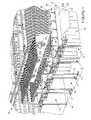
- FIG. 1is a perspective illustration of a plurality of modular, collapsible data center unit structures disposed adjacent one another to help form a data center, in accordance with one embodiment of the present disclosure
- FIG. 2is an enlarged perspective view of a portion of one of the data center unit structures of the present disclosure even more fully illustrating a plurality of foldable cable tray supports, along with one cable tray, that each unit structure incorporates;
- FIG. 2 ais a perspective view of a portion of one form of pivoting mechanism that may be used to support the hangers, which involves the use of an elongated tubular support member which is able to rotate;
- FIG. 2 bis an enlarged perspective view of the saddle-like strap shown in FIG. 2 a which may be used to help enable rotational movement of the elongated tubular support member shown in FIG. 2 a;
- FIG. 3is a perspective view of one of the data center unit structures shown in FIG. 1 but with the unit structure in its collapsed configuration for shipping;
- FIG. 4is a perspective view of two data center unit structures in their collapsed configurations and positioned back-to-back, which forms a highly compact package suitable for placement in a standard shipping container;
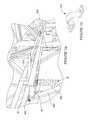
- FIG. 5is a high level side view of a portion of a data center in which two of the data center unit structures are shown forming an elongated row, and further illustrating a modular penthouse exhaust structure that resides above the data center unit structures to facilitate the exhaust of hot air from hot air isles formed between rows of equipment racks positioned underneath the unit structures;
- FIG. 6is an enlarged view of just circled portion 6 in FIG. 5 ;
- FIG. 6 ais a perspective view of a portion of one end of the data center illustrating how hot air from a hot air isle may be exhausted through the modular penthouse exhaust structure;
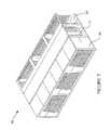
- FIG. 7is a perspective view of modular cooling unit that may be used with the data center unit structures to help form a modular data center;
- FIG. 8shows a perspective view of one of the modular cooling units arranged adjacent the ends of a plurality of the data center unit structures
- FIG. 9is a high level top view illustrating the components of the modular cooling unit shown in FIG. 7 ;
- FIG. 10is a high level front view of the modular cooling unit of FIG. 9 ;
- FIG. 11is a high level side view of the cooling unit of FIG. 9 in accordance with arrow 11 in FIG. 10 ;
- FIG. 12is a high level perspective view of just a filter unit of the modular cooling unit
- FIG. 13is a high level perspective view of just a fan unit of the modular cooling unit
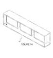
- FIG. 14is a high level perspective view of just a cooling module media unit of the modular cooling unit
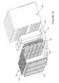
- FIG. 15is another high level perspective view of the modular cooling unit but with its outer wall structure removed, and further with the wall structure surrounding one of the fan units removed;
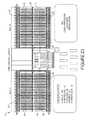
- FIG. 16further illustrates components that may be included within each of the modular cooling units
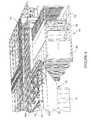
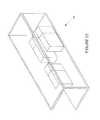
- FIG. 17is a perspective view of one modular cooling unit located adjacent to a plurality of the data center unit structures illustrating how hot exhaust (i.e., return) air from one of the hot isles may be returned to the modular cooling unit;
- FIG. 18is a high level overhead view of a portion of a data center illustrating a plurality of modular sections that together form a “power hall” for a data center, and which are located adjacent to a plurality of the data center unit structures;
- FIG. 19illustrates a modular power supply unit for constructing the power hall shown in FIG. 18 ;
- FIG. 20illustrates a modular power cabinet unit for use in constructing the power hall shown in FIG. 18 ;
- FIG. 21shows a modular UPS unit for use in constructing the power hall shown in FIG. 18 ;
- FIG. 22shows a modular PDU unit for use in constructing the power hall shown in FIG. 18 ;
- FIG. 23is an overhead view of one exemplary layout for a data center that makes use of two halls separated by a modular office/storage area and a modular water treatment unit;
- FIG. 24is a perspective view of another embodiment of the unit structure.
- FIG. 25is a perspective view of a portion of the unit structure of FIG. 24 illustrating a centrally located cable tray.
- FIG. 1there is shown a portion of a modular data center facility 10 incorporating a plurality of modular, collapsible data center unit structures 12 (hereinafter simply “unit structures 12 ”) for forming a rapidly deployable data center.
- Each of the unit structures 12forms an elongated structure which may be used to channel both cold air from one or more air conditioning systems through a cold aisle 15 which separates parallel rows of equipment racks 14 , as well to help channel hot air from a hot aisle.
- Each unit structure 12is adapted to be supported by structural support columns 16 at a predetermined height above a floor 18 of the data center facility 10 .
- FIG. 1illustrates a plurality of the unit structures 12 positioned in side-by-side fashion. Adjacent ones of the unit structures 12 are further spaced apart a predetermined distance. This spacing forms hot aisles 17 between adjacent ones of the unit structures 12 .
- the modular data center facility 10may also include one or more modular penthouse exhaust structures 20 for receiving hot air from the hot aisles 17 and exhausting the hot air from the modular data center facility 10 .
- the modular penthouse exhaust structures 20receive the hot air flow from the hot aisles 17 through openings 24 in ceiling panels 26 of the unit structures 12 . This feature will be explained in greater detail in the following paragraphs.
- a plurality of bridging ceiling panels 26 aare also used to bridge the spacing between adjacent ones of the unit structures 12 , and thus ensure that hot air being drawn out from the hot aisles 17 is exhausted through the openings 24 .
- each unit structure 12has a frame structure 28 that supports a plurality of the ceiling panels 26 to form a roof-like structure.
- a perimeter frame structure 30may be coupled to the structural support columns 16 .
- the perimeter frame structure 30may be used to support collapsible (i.e., foldable) panels 32 to help maintain cold air from air conditioning systems within the cold aisles 15 between adjacent rows of equipment racks 14 .
- the perimeter frame structure 30also may include a plurality of pivotally secured hangers 34 and 36 that are supported from the frame structure 30 . Hangers 34 in this example are supported from separate cross members 33 and are able to pivot into the orientation shown in FIG. 2 for use.
- Hangers 34may have a plurality of cable trays 38 secured thereto and hangers 36 may likewise have a plurality of cable trays 40 secured thereto. Cable trays 38 and 40 may be used to support a variety of different types of cables such as network cables, power cables, etc., that need to be routed through the data center facility 10 to equipment components mounted in the rows of equipment racks 14 .
- a roof panel 42may also be secured to the perimeter frame structure 30 . Roof panel 42 forms a partition which further helps to channel cold air from one or more air conditioning systems through the cold aisle 15 formed between adjacent rows of equipment racks 14 .
- the hanger 36may be representative of, or identical, to the construction used for the hangers 34 .
- the ability of the hanger 36 to pivotis achieved, in one example, by using a round, rigid, tubular, elongated support member 36 a , which may be supported for rotational movement at its opposing ends by a saddle-like bracket 36 b , where the saddle-like bracket 36 b is fixedly secured to a portion of the perimeter frame structure 30 by suitable fasteners (not shown).
- the saddle like bracket 36 bis also shown in FIG. 2 b .
- any other suitable hinge or hinge-like structurescould be implemented to enable pivoting motion of the hanger 36 .
- FIG. 2 aalso shows that the hanger 36 may include a plurality of depending structural members 36 c which may support the cable trays 40 .
- the depending structural members 36 cmay be fixedly secured to the elongated support member 36 a so as to be able to rotate with the elongated support member 36 a , and thus be able to present the trays 40 in an operative position below the perimeter frame structure 30 or in a stowed orientation.
- One or more braces 36 dmay be used to brace the hanger 36 in its operative position.
- the braces 36 dmay each be secured at one end to the perimeter frame structure 30 by suitable brackets 36 e that enable pivoting motion thereof, and at their opposite ends to the depending structural members 36 c .
- braces 36 dThis enables the braces 36 d to be pivoted upwardly into stowed configurations once detached from the structural members 36 c . Still, the braces 36 d are able to be quickly and easily secured to the structural members 36 c of the hanger 36 , to brace the hanger 36 once the hanger 36 is lowered into its operative position.
- the hangers 36as well as the hangers 34 , may be constructed from suitable structural supports and brackets to permit their easy removal from the perimeter frame structure 30 , instead of a folding motion. Depending on how many cable trays 38 and 40 are employed, and the overall dimensions of the unit structure 12 , it may be helpful or necessary to have the hangers 34 and or 36 supported by structure that is removable completely from the perimeter frame structure 30 when the unit structure is prepared for shipping.
- each modular penthouse exhaust structure 20may include a total of six exhaust fans 44 arranged as two opposing rows of three fans.
- the openings 24 in the ceiling panels 26may also have positioned therein modulated louver assemblies 48 that may be electronically modulated to tailor the flow of hot air from the hot aisles 17 that may be drawn into the penthouse exhaust structures 20 .
- modulated louver assemblies 48may be electronically modulated to tailor the flow of hot air from the hot aisles 17 that may be drawn into the penthouse exhaust structures 20 .
- Suitable air flow and/or temperature control monitoring systemsmay be provided for this purpose.
- one of the unit structures 12is shown in its collapsed configuration.
- the unit structure 12has the hangers 34 and 36 pivoted into a stowed position where they are held such that they do not protrude below panel portions 32 a of panels 32 .
- Panels 32are also pivoted such that they extend parallel to the ceiling panels 26 .
- the unit structure 12forms an elongated, relatively narrow configuration with the hangers 34 and 36 , as well as the cable trays 38 and 40 , tucked up between the panel portions 32 a .
- This configurationalso forms a highly space efficient configuration from a shipping and packaging standpoint.
- FIG. 4illustrates a pair of the unit structures 12 in their collapsed configurations positioned back-to-back.
- Each of the unit structures 12when in its collapsed configuration, may have dimensions of approximately 12192 mm (40.0 feet) in overall length by 3658 mm (12.0 feet) in width and 2848 mm (5 feet and 5.22 inches) in height.
- the back-to-backpositioned pair of unit structures 12 in FIG.
- the collapsed configurationenables a pair of the unit structures 12 to be efficiently packaged for shipping.
- FIG. 7illustrates a modular cooling unit 50 that may be used to help form the modular data center facility 10 of FIG. 1 .
- the modular cooling 50may have dimensions of about 13761 mm (45 feet) in length, about 7315 mm (24 feet) in width and about 3500 mm (11 feet and 5.8 inches) in overall height.
- the cooling module unit 50is very similar in overall dimensions to the back-to-back pair of unit structures 12 shown in FIG. 4 , which again facilitates shipping in a standardized shipping container.
- FIG. 8one modular cooling unit 50 can be seen arranged so that its major length extends perpendicular to the major length of the unit structures 12 , and such that it is positioned adjacent one of the ends of the unit structures 12 . This enables the modular cooling unit 50 to supply cold air to the cold aisles 15 formed by a plurality of the unit structures 12 .
- each modular cooling unit 50may form an evaporative (i.e., adiabatic) cooling unit that includes a filter unit 52 , a media unit 54 , a fan unit 56 , and may draw on the order of 900 kW.
- FIGS. 12-14further illustrate these components.
- Each fan unit 56may include a plurality of fans 56 a , and in one embodiment a total of twelve such fans 56 a configured in three separate cabinets 56 b as shown in FIG. 15 .
- FIG. 15further illustrates that the cabinets 56 b each may have an isolated access through a door 56 c.
- FIG. 16illustrates that the media unit 54 may include three independent evaporative cooling modules 54 a - 54 c having four cooling stages each.
- a DX coil and dampers 60may optionally be included.
- the filter unit 52may include a plurality of filters 52 a , an electronically actuated return air damper 52 b for controlling a return air flow into the modular cooling unit 50 , and an electronically actuated outside air louver and damper 52 c for controlling the flow of outside (ambient air) drawn into the cooling unit 50 .
- FIG. 17illustrates how hot air 17 a in the hot air isles 17 may be returned within an area 64 formed between the ceiling panels 26 / 26 a (the panels 26 / 26 a being visible only in FIG.
- Cool air 62is supplied into each of the cold aisles 15 by the modular cooling units 50 , which are able to draw in outside air 63 .
- FIG. 18illustrates one embodiment of a modular “power hall” 70 that may be used in connection with the unit structures 12 to form the modular data center facility 10 .
- the modular power hall 70may be made up of one or more modular power supply units 72 ( FIG. 19 ), one or more modular power cabinet units 74 ( FIG. 20 ), one or more modular UPS (uninterruptible power supply) units 76 and one or more modular PDU (power distribution unit) units 78 , as well as any other type of power component or subsystem.
- FIG. 18also shows a plurality of electrical bus bars 80 that may be used to connect the various components in each of the modular units 72 - 78 as needed to distribute power.
- the modular power supply units 72may each include a main bus, for example a 5000 A main bus for supplying 100 kA at 480V.
- a plurality of main breakers and distributed breakersmay also be included along with a suitable power control system and a power quality meter.
- the modular power cabinet units 74may each include a 1600 A bus main bus for delivering 65 kA at 480V. Power breakers and distribution breakers may be configured as needed for specific applications.
- the modular UPS units 76may each include parallel 400 kVA/400 kW modules to provide 750 kW of backup power. However, it will be appreciated that the UPS units 76 may be configured as needed to suit a specific application.
- Each of the modular PDU units 78may be configured to provide 300 kVA 480/208/120V, or a different selected electrical output.
- Load distribution breakersmay also be mounted in cabinets (not shown) that are in turn mounted to the sides of a frame of each PDU contained in the modular PDU unit 78 .
- Each of the modular units 72 - 78may have similar or identical dimensions.
- the dimensions of the modular units 72 - 78are identical with a length of 12192 mm (40 feet), a width of 3658 mm (12 feet) and a height of 3500 mm (11 feet and 5.8 inches). Obviously these dimensions may be varied slightly if needed.
- the modular units 72 - 78may have length and width dimensions that are the same as the unit structures 12 . These dimensions enable shipping of the modular units 72 - 78 in conventional shipping containers.
- each of the modular units 72 - 78may include a frame structure 73 having one or more of components secured thereto such as a floor 73 a and one or more wall portions 73 b .
- the modular units 72 - 78are also rapidly deployable when they are received at the destination site.
- the modular configuration of the units 72 - 78allows for easily expanding the power supply capabilities of the power hall 70 as data center needs grow.
- FIG. 23shows an overhead view of one example of an implementation of the modular data center facility 10 .
- the unit structures 12are grouped into two halls, “Hall A” and “Hall B”, separated by a modular office/storage section area 80 .
- a modular water treatment section 82may include water treatment equipment.
- Rows 84 of modular cooling units 50may be arranged adjacent the rows of unit structures 12 .
- a row of modular penthouse exhaust structures 20(not shown in FIG. 23 ) may extend over a hallway area 86 , perpendicularly to the unit structures 12 , to interface with the hot aisles 17 adjacent the unit structures 12 .
- a modular room 86may be included for other data center or office equipment.
- a unit structure 100is shown in accordance with another embodiment of the present disclosure.
- the unit structure 100is this example also has additional structural columns 102 that may be used to help form a hot aisle with one or more doors at opposing ends of the unit structure 100 .
- the unit structure 100can also be seen in FIG. 25 to include a central, elongated tray 104 that runs a substantial portion of a full length of the unit structure 100 .
- the central, elongated tray 104may include a pair of curving tray portions 106 that enable cables to be fed out from the central, elongated tray 104 .
- the central, elongated tray 104 and the curving tray portions 106may each include a plurality of posts 108 to help retain cables within the trays 104 and 106 .
- the various embodiments of the present disclosuremay incorporate built in lighting fixtures, as well as one or more lengths of built in conduit for the delivery of water or a different fire suppression agent.
- the cable trays 38 , 40 and 104may be used to divide and route specific types of cabling (i.e., optical, power, network, etc.) depending on user requirements or preferences.
- the various embodiments of the modular data center facility 10enable the various modular components that are used to form the data center to be easily shipped to a destination site and constructed in a desired configuration.
- the modular components the data center facility 10can be rapidly deployed so that a fully functioning data center can be constructed much more quickly than a conventional “stick built” data center structure.
Landscapes
- Engineering & Computer Science (AREA)
- Microelectronics & Electronic Packaging (AREA)
- Computer Hardware Design (AREA)
- General Engineering & Computer Science (AREA)
- Architecture (AREA)
- Physics & Mathematics (AREA)
- Thermal Sciences (AREA)
- Structural Engineering (AREA)
- Civil Engineering (AREA)
- Electromagnetism (AREA)
- Health & Medical Sciences (AREA)
- Epidemiology (AREA)
- Public Health (AREA)
- Ventilation (AREA)
- Building Environments (AREA)
- Cooling Or The Like Of Electrical Apparatus (AREA)
- Arrangements For Transmission Of Measured Signals (AREA)
- Conveying And Assembling Of Building Elements In Situ (AREA)
- Floor Finish (AREA)
Abstract
Description
Claims (18)
Priority Applications (16)
| Application Number | Priority Date | Filing Date | Title |
|---|---|---|---|
| US14/504,081US9572288B2 (en) | 2013-10-03 | 2014-10-01 | System and method for modular data center |
| JP2016519809AJP6243525B2 (en) | 2013-10-03 | 2014-10-02 | Modular data center system and method |
| CN201480054373.5ACN105594313B (en) | 2013-10-03 | 2014-10-02 | Systems and methods for forming a modular data center |
| RU2016107438ARU2700001C2 (en) | 2013-10-03 | 2014-10-02 | Modular data processing centre and formation method thereof |
| CA2922525ACA2922525C (en) | 2013-10-03 | 2014-10-02 | System and method for forming modular data center |
| MYPI2016700615AMY178369A (en) | 2013-10-03 | 2014-10-02 | System and method for modular data center |
| PCT/US2014/058771WO2015051086A1 (en) | 2013-10-03 | 2014-10-02 | System and method for modular data center |
| NZ717781ANZ717781B2 (en) | 2013-10-03 | 2014-10-02 | System and method for modular data center |
| KR1020167009325AKR102234195B1 (en) | 2013-10-03 | 2014-10-02 | System and method for modular data center |
| HRP20190906TTHRP20190906T1 (en) | 2013-10-03 | 2014-10-02 | SYSTEM AND PROCEDURE FOR DESIGNING A MODULAR DATA CENTER |
| EP14796929.9AEP3053423B1 (en) | 2013-10-03 | 2014-10-02 | System and method for forming modular data center |
| SG11201601539TASG11201601539TA (en) | 2013-10-03 | 2014-10-02 | System and method for modular data center |
| US15/002,661US9850655B2 (en) | 2013-10-03 | 2016-01-21 | System and method for modular data center |
| PH12016500373APH12016500373B1 (en) | 2013-10-03 | 2016-02-24 | System and method for modular data center |
| US15/274,398US10172261B2 (en) | 2013-10-03 | 2016-09-23 | System and method for modular data center |
| PH12019501746APH12019501746A1 (en) | 2013-10-03 | 2019-07-29 | System and method for modulator data center |
Applications Claiming Priority (2)
| Application Number | Priority Date | Filing Date | Title |
|---|---|---|---|
| US201361886402P | 2013-10-03 | 2013-10-03 | |
| US14/504,081US9572288B2 (en) | 2013-10-03 | 2014-10-01 | System and method for modular data center |
Related Child Applications (2)
| Application Number | Title | Priority Date | Filing Date |
|---|---|---|---|
| US15/002,661Continuation-In-PartUS9850655B2 (en) | 2013-10-03 | 2016-01-21 | System and method for modular data center |
| US15/274,398ContinuationUS10172261B2 (en) | 2013-10-03 | 2016-09-23 | System and method for modular data center |
Publications (2)
| Publication Number | Publication Date |
|---|---|
| US20150098177A1 US20150098177A1 (en) | 2015-04-09 |
| US9572288B2true US9572288B2 (en) | 2017-02-14 |
Family
ID=52776769
Family Applications (3)
| Application Number | Title | Priority Date | Filing Date |
|---|---|---|---|
| US14/504,081ActiveUS9572288B2 (en) | 2013-10-03 | 2014-10-01 | System and method for modular data center |
| US15/002,661ActiveUS9850655B2 (en) | 2013-10-03 | 2016-01-21 | System and method for modular data center |
| US15/274,398ActiveUS10172261B2 (en) | 2013-10-03 | 2016-09-23 | System and method for modular data center |
Family Applications After (2)
| Application Number | Title | Priority Date | Filing Date |
|---|---|---|---|
| US15/002,661ActiveUS9850655B2 (en) | 2013-10-03 | 2016-01-21 | System and method for modular data center |
| US15/274,398ActiveUS10172261B2 (en) | 2013-10-03 | 2016-09-23 | System and method for modular data center |
Country Status (12)
| Country | Link |
|---|---|
| US (3) | US9572288B2 (en) |
| EP (1) | EP3053423B1 (en) |
| JP (1) | JP6243525B2 (en) |
| KR (1) | KR102234195B1 (en) |
| CN (1) | CN105594313B (en) |
| CA (1) | CA2922525C (en) |
| HR (2) | HRP20190906T1 (en) |
| MY (1) | MY178369A (en) |
| PH (2) | PH12016500373B1 (en) |
| RU (1) | RU2700001C2 (en) |
| SG (1) | SG11201601539TA (en) |
| WO (1) | WO2015051086A1 (en) |
Cited By (7)
| Publication number | Priority date | Publication date | Assignee | Title |
|---|---|---|---|---|
| US10172261B2 (en)* | 2013-10-03 | 2019-01-01 | Vertiv Corporation | System and method for modular data center |
| US20190104636A1 (en)* | 2017-10-04 | 2019-04-04 | Google Llc | Managing a data center |
| US10499533B1 (en)* | 2018-08-01 | 2019-12-03 | Fujitsu Limited | Container cabling systems and methods |
| US20200141117A1 (en)* | 2018-11-06 | 2020-05-07 | NTT Worldwide Telecommunications Corporation | Data center |
| US10888013B2 (en) | 2017-10-04 | 2021-01-05 | Google Llc | Managing a data center |
| US11071236B2 (en) | 2019-04-04 | 2021-07-20 | Carrier Corporation | Air management system for room containing electrical equipment |
| US11085666B2 (en) | 2018-05-22 | 2021-08-10 | Johnson Controls Technology Company | Collapsible roof top unit systems and methods |
Families Citing this family (31)
| Publication number | Priority date | Publication date | Assignee | Title |
|---|---|---|---|---|
| US9606316B1 (en)* | 2014-05-01 | 2017-03-28 | Amazon Technologies, Inc. | Data center infrastructure |
| NO341254B1 (en)* | 2015-11-02 | 2017-09-25 | Orient Holding As | Heating and cooling system of a modular residential building |
| DE102016100668B4 (en)* | 2016-01-15 | 2025-03-20 | ICT Facilities GmbH | Air conditioning system, data center and method for air conditioning a data center |
| CN205875821U (en)* | 2016-01-21 | 2017-01-11 | 力博特公司 | System for be used for modularization data center |
| US11497133B2 (en) | 2016-01-29 | 2022-11-08 | Bripco Bvba | Method of making a data centre |
| CN109219992B (en)* | 2016-06-03 | 2021-11-23 | 日立能源瑞士股份公司 | Support structure for supporting an electrical component, system comprising a support structure and method of manufacturing a support structure |
| TWI640859B (en)* | 2016-07-19 | 2018-11-11 | 美商谷歌有限責任公司 | Modular data center systems and a method of conditioning a data center |
| CN107683072A (en)* | 2017-10-11 | 2018-02-09 | 电子科技大学 | A data center cooling system based on thermoelectric devices |
| CN108222570B (en)* | 2018-03-21 | 2023-09-08 | 中国联合网络通信集团有限公司 | Communication machine room |
| US11382228B2 (en)* | 2018-04-04 | 2022-07-05 | Hewlett-Packard Development Company, L.P. | Dual-axis hinge assemblies |
| EP3834065A4 (en) | 2018-08-07 | 2022-06-29 | Levi Strauss & Co. | Laser finishing design tool |
| US10925184B2 (en)* | 2018-11-05 | 2021-02-16 | Ntt Ltd Japan Corporation | Data center |
| JP6613012B1 (en)* | 2018-11-05 | 2019-11-27 | エヌ・ティ・ティ国際通信株式会社 | Data center |
| CN109678051A (en)* | 2018-12-18 | 2019-04-26 | 筑梦高科建筑有限公司 | A kind of rail system carrying building |
| CN110043076A (en)* | 2019-03-20 | 2019-07-23 | 上海德衡数据科技有限公司 | It is a kind of prefabricated with stacking the data center that combines and assembly method |
| WO2020248536A1 (en)* | 2019-06-10 | 2020-12-17 | 北京秦淮数据有限公司 | Extended data center |
| EP3786558A1 (en) | 2019-08-30 | 2021-03-03 | Ovh | Heat exchanger panel and method for mounting thereof to a rack structure |
| KR20210072857A (en)* | 2019-12-09 | 2021-06-18 | 삼성디스플레이 주식회사 | Display device |
| CN113090149B (en)* | 2019-12-23 | 2022-08-09 | 北京小米移动软件有限公司 | Hinge structure and folding electronic device |
| US11324146B2 (en)* | 2020-07-02 | 2022-05-03 | Google Llc | Modular data center serverhall assembly |
| US11920867B2 (en)* | 2020-08-26 | 2024-03-05 | Baidu Usa Llc | Highly modularized cooling system design |
| US11228166B1 (en)* | 2020-09-23 | 2022-01-18 | M.C. Dean Inc. | Free-standing cable tray support system and method of assembly |
| CN112991959B (en)* | 2021-03-31 | 2023-09-29 | 上海天马微电子有限公司 | Foldable display module, manufacturing method thereof and foldable display device |
| CN115234568B (en)* | 2021-04-25 | 2023-09-19 | 北京小米移动软件有限公司 | Connection module and display terminal |
| KR20230038853A (en)* | 2021-09-13 | 2023-03-21 | 엘지디스플레이 주식회사 | Foldable display apparatus |
| US11940198B2 (en)* | 2021-12-01 | 2024-03-26 | Lineage Logistics, LLC | Automated blast cell loading and unloading |
| US11946269B2 (en)* | 2022-03-21 | 2024-04-02 | Nautilus True, Llc | Modular integrated system modules |
| BR102022010903A2 (en)* | 2022-06-03 | 2023-12-19 | Scala Data Centers S.A. | DATA PROCESSING CENTER MODULE CONSISTING OF PREFABRICATED AND TRANSPORTABLE SEGMENTS, METHOD OF CONSTRUCTION OF DATA PROCESSING CENTER MODULE, DATA PROCESSING CENTER CONSTITUTED FROM SAID MODULE AND METHOD OF CONSTRUCTION OF SAID DATA PROCESSING CENTER |
| CN115669247B (en)* | 2022-09-15 | 2023-05-30 | 航霈科技(深圳)有限公司 | Airflow channel folding assembly, data center system and installation method |
| KR102503776B1 (en) | 2022-09-29 | 2023-02-24 | 주식회사 이온 | Smart cabinet for high-density data center server and its operation method |
| GB2625510B (en)* | 2022-11-25 | 2025-01-22 | Pripco Ltd | Improvements in and relating to data centre construction |
Citations (15)
| Publication number | Priority date | Publication date | Assignee | Title |
|---|---|---|---|---|
| US7269753B2 (en) | 2004-08-27 | 2007-09-11 | Hewlett-Packard Development Company, L.P. | Mapping power system components |
| US7278273B1 (en)* | 2003-12-30 | 2007-10-09 | Google Inc. | Modular data center |
| US20080135691A1 (en)* | 2006-12-11 | 2008-06-12 | Anvil International, Lp. | Securing system |
| US7395444B2 (en) | 2003-09-23 | 2008-07-01 | American Power Conversion Corporation | Power status notification |
| US20080277391A1 (en) | 2007-05-07 | 2008-11-13 | International Business Machines Corporation | Mobile, Robotic Crate |
| US7500120B2 (en) | 2003-10-16 | 2009-03-03 | International Business Machines Corporation | Apparatus has service processor determining interconnection between uninterruptible power supplies and system resources using configuration file that is stored in memory |
| US20090287943A1 (en) | 2008-05-15 | 2009-11-19 | International Business Machines Corporation | Mapping power domains in a data center |
| US20090287949A1 (en) | 2008-05-15 | 2009-11-19 | International Business Machines Corporation | Managing Power Domains In A Data Center |
| GB2467808A (en) | 2009-06-03 | 2010-08-18 | Moduleco Ltd | Data centre cooling arrangements |
| US7917792B2 (en) | 2008-02-22 | 2011-03-29 | International Business Machines Corporation | System for modulating signals over power lines to understand the power distribution tree |
| WO2011038348A1 (en) | 2009-09-28 | 2011-03-31 | Amazon Technologies, Inc. | Modular system for data center |
| US20110108207A1 (en)* | 2009-11-09 | 2011-05-12 | LDM Products, Inc. | Retractable computer rack aisle roof |
| WO2012118554A1 (en) | 2011-03-02 | 2012-09-07 | Ietip Llc | Modular it rack cooling assemblies and methods for assembling same |
| US8320125B1 (en) | 2007-06-29 | 2012-11-27 | Exaflop Llc | Modular data center cooling |
| WO2014039524A2 (en) | 2012-09-04 | 2014-03-13 | Amazon Technologies, Inc. | Expandable data center with movable wall |
Family Cites Families (61)
| Publication number | Priority date | Publication date | Assignee | Title |
|---|---|---|---|---|
| US2677580A (en)* | 1951-11-10 | 1954-05-04 | Minzenmayer Charles | Portable elevator for overhead installations |
| US2918164A (en)* | 1955-03-02 | 1959-12-22 | Bendix Aviat Corp | Loader mechanism |
| US4170852A (en) | 1977-11-28 | 1979-10-16 | Danis Industries Corporation | Articulated prefabricated modular building and method of erecting the same |
| JP2553716Y2 (en)* | 1991-02-08 | 1997-11-12 | 株式会社 ブレスト工業研究所 | Wiring duct mounting structure |
| JPH05296231A (en)* | 1992-04-21 | 1993-11-09 | Yokohama Rubber Co Ltd:The | Rubber roll and its manufacture |
| US5440894A (en)* | 1993-05-05 | 1995-08-15 | Hussmann Corporation | Strategic modular commercial refrigeration |
| US5524776A (en)* | 1993-12-17 | 1996-06-11 | Hall; Roger W. | Low inclination push back storage rack system |
| ATE225444T1 (en)* | 1996-04-10 | 2002-10-15 | Erico Int Corp | CEILING SUSPENDERS |
| US5938047A (en)* | 1998-03-27 | 1999-08-17 | Ellis; Chris | Material storage and retrieval assembly |
| US7100332B2 (en)* | 2004-08-26 | 2006-09-05 | Loesch Ivan L | Unfolding modular building system |
| US7259963B2 (en)* | 2004-12-29 | 2007-08-21 | American Power Conversion Corp. | Rack height cooling |
| US20160281348A9 (en)* | 2005-05-06 | 2016-09-29 | Best Technologies, Inc. | Modular building utilities systems and methods |
| US7841199B2 (en)* | 2005-05-17 | 2010-11-30 | American Power Conversion Corporation | Cold aisle isolation |
| US7658039B2 (en)* | 2005-09-22 | 2010-02-09 | Ziegelman Robert L | Housing modules with solar panels and buildings formed from stacked modules |
| US7365973B2 (en)* | 2006-01-19 | 2008-04-29 | American Power Conversion Corporation | Cooling system and method |
| CN201018612Y (en)* | 2007-03-27 | 2008-02-06 | 华为技术有限公司 | Main distributing frame |
| US9622389B1 (en) | 2007-06-14 | 2017-04-11 | Switch, Ltd. | Electronic equipment data center and server co-location facility configurations and method of using the same |
| US8469782B1 (en) | 2007-06-14 | 2013-06-25 | Switch Communications Group, LLC | Data center air handling unit |
| US8180495B1 (en)* | 2007-06-14 | 2012-05-15 | Switch Communications Group LLC | Air handling control system for a data center |
| US8072780B1 (en) | 2007-06-14 | 2011-12-06 | Switch Communications Group LLC | Integrated wiring system and thermal shield support apparatus for a data center |
| US8523643B1 (en) | 2007-06-14 | 2013-09-03 | Switch Communications Group LLC | Electronic equipment data center or co-location facility designs and methods of making and using the same |
| US8456840B1 (en) | 2007-07-06 | 2013-06-04 | Exaflop Llc | Modular data center cooling |
| US7656660B2 (en)* | 2007-11-20 | 2010-02-02 | International Business Machines Corporation | Airflow arresting apparatus and method for facilitating cooling of an electronics rack of a data center |
| US9066450B2 (en)* | 2008-10-24 | 2015-06-23 | Wright Line, Llc | Data center air routing system |
| US20100235206A1 (en) | 2008-11-14 | 2010-09-16 | Project Frog, Inc. | Methods and Systems for Modular Buildings |
| US8783336B2 (en) | 2008-12-04 | 2014-07-22 | Io Data Centers, Llc | Apparatus and method of environmental condition management for electronic equipment |
| US7990710B2 (en) | 2008-12-31 | 2011-08-02 | Vs Acquisition Co. Llc | Data center |
| US20100181082A1 (en)* | 2009-01-22 | 2010-07-22 | The Viking Corporation | System For Improving Water Delivery Time In Dry Pipe Sprinkler System |
| US20100248609A1 (en)* | 2009-03-24 | 2010-09-30 | Wright Line, Llc | Assembly For Providing A Downflow Return Air Supply |
| US8031468B2 (en)* | 2009-06-03 | 2011-10-04 | American Power Conversion Corporation | Hot aisle containment cooling unit and method for cooling |
| US7944692B2 (en)* | 2009-06-12 | 2011-05-17 | American Power Conversion Corporation | Method and apparatus for installation and removal of overhead cooling equipment |
| US9388561B2 (en)* | 2009-07-15 | 2016-07-12 | Frank Johnson | Modular construction mold apparatus and method for constructing concrete buildings and structures |
| US8233270B2 (en)* | 2009-11-20 | 2012-07-31 | Turbine Air Systems, Ltd. | Modular data center |
| JP5441212B2 (en)* | 2009-12-22 | 2014-03-12 | 鹿島建設株式会社 | Local circulation air conditioning system in data center |
| US9670689B2 (en) | 2010-04-06 | 2017-06-06 | Schneider Electric It Corporation | Container based data center solutions |
| US8974274B2 (en)* | 2010-04-16 | 2015-03-10 | Google Inc. | Evaporative induction cooling |
| US8407004B2 (en)* | 2010-04-29 | 2013-03-26 | Schneider Electric It Corporation | Airflow detector and method of measuring airflow |
| WO2011146063A1 (en)* | 2010-05-20 | 2011-11-24 | Hewlett-Packard Development Company, L.P. | Data center cooling |
| WO2011163532A2 (en) | 2010-06-23 | 2011-12-29 | Earl Keisling | Space-saving high-density modular data center and an energy-efficient cooling system |
| RU2444868C1 (en)* | 2010-07-13 | 2012-03-10 | Эндал Инвестментс Лимитед | Modular processing centre and functioning thereof |
| US8893813B2 (en) | 2010-08-06 | 2014-11-25 | Engineered Corrosion Solutions, Llc | Fire protection sprinkler system with oxygen corrosion sensitive coupon assembly and method of monitoring corrosion in a fire protection sprinkler system |
| JP5500528B2 (en)* | 2011-03-18 | 2014-05-21 | 清水建設株式会社 | Unit type data center |
| US9945142B2 (en)* | 2011-04-06 | 2018-04-17 | Fmr Llc | Modular data center |
| CN202110485U (en)* | 2011-07-17 | 2012-01-11 | 北京天云动力科技有限公司 | Air flow organization optimizing device |
| GB201113556D0 (en)* | 2011-08-05 | 2011-09-21 | Bripco Bvba | Data centre |
| CN104024975B (en)* | 2011-11-03 | 2018-04-10 | 美国北卡罗来纳康普公司 | For the refrigerating module of modular data center and the system including the refrigerating module and at least one server module |
| US8708164B2 (en)* | 2011-12-06 | 2014-04-29 | Upsite Technologies, Inc. | Internal seals for server racks |
| JP5842936B2 (en)* | 2012-01-30 | 2016-01-13 | 富士通株式会社 | Air conditioning system |
| DE202013012529U1 (en)* | 2012-03-08 | 2017-04-27 | Google Inc. | Control of data center cooling |
| US9671837B2 (en) | 2012-10-04 | 2017-06-06 | Compass Datacenters, Llc | Air dam for a datacenter facility |
| US9192077B2 (en)* | 2012-04-10 | 2015-11-17 | Facebook, Inc. | Baffle for air flow redirection |
| JP5084964B1 (en)* | 2012-04-19 | 2012-11-28 | 新日鉄エンジニアリング株式会社 | Server rack indoor system |
| US9204576B2 (en)* | 2012-09-14 | 2015-12-01 | Cisco Technolgy, Inc. | Apparatus, system, and method for configuring a system of electronic chassis |
| CA2803497C (en) | 2012-12-12 | 2018-08-21 | Vert.Com, Inc. | Prefabricated vertical data center modules and method of large-scale deployment |
| US9563216B1 (en)* | 2013-03-14 | 2017-02-07 | Google Inc. | Managing power between data center loads |
| US9198331B2 (en) | 2013-03-15 | 2015-11-24 | Switch, Ltd. | Data center facility design configuration |
| US9247659B1 (en)* | 2013-06-21 | 2016-01-26 | Amazon Technologies, Inc. | Slab-based cooling |
| US9007221B2 (en)* | 2013-08-16 | 2015-04-14 | Cisco Technology, Inc. | Liquid cooling of rack-mounted electronic equipment |
| US9572288B2 (en)* | 2013-10-03 | 2017-02-14 | Liebert Corporation | System and method for modular data center |
| US9357681B2 (en)* | 2014-05-22 | 2016-05-31 | Amazon Technologies, Inc. | Modular data center row infrastructure |
| US9510485B2 (en)* | 2015-01-06 | 2016-11-29 | Dell Products, L.P. | Expandable, modular information technology facility with modularly expandable cooling |
- 2014
- 2014-10-01USUS14/504,081patent/US9572288B2/enactiveActive
- 2014-10-02MYMYPI2016700615Apatent/MY178369A/enunknown
- 2014-10-02WOPCT/US2014/058771patent/WO2015051086A1/enactiveApplication Filing
- 2014-10-02EPEP14796929.9Apatent/EP3053423B1/enactiveActive
- 2014-10-02HRHRP20190906TTpatent/HRP20190906T1/enunknown
- 2014-10-02KRKR1020167009325Apatent/KR102234195B1/enactiveActive
- 2014-10-02JPJP2016519809Apatent/JP6243525B2/enactiveActive
- 2014-10-02CACA2922525Apatent/CA2922525C/enactiveActive
- 2014-10-02SGSG11201601539TApatent/SG11201601539TA/enunknown
- 2014-10-02RURU2016107438Apatent/RU2700001C2/enactive
- 2014-10-02CNCN201480054373.5Apatent/CN105594313B/enactiveActive
- 2016
- 2016-01-21USUS15/002,661patent/US9850655B2/enactiveActive
- 2016-02-24PHPH12016500373Apatent/PH12016500373B1/enunknown
- 2016-06-09HRHRP20201532TTpatent/HRP20201532T1/enunknown
- 2016-09-23USUS15/274,398patent/US10172261B2/enactiveActive
- 2019
- 2019-07-29PHPH12019501746Apatent/PH12019501746A1/enunknown
Patent Citations (17)
| Publication number | Priority date | Publication date | Assignee | Title |
|---|---|---|---|---|
| US7395444B2 (en) | 2003-09-23 | 2008-07-01 | American Power Conversion Corporation | Power status notification |
| US7500120B2 (en) | 2003-10-16 | 2009-03-03 | International Business Machines Corporation | Apparatus has service processor determining interconnection between uninterruptible power supplies and system resources using configuration file that is stored in memory |
| US7278273B1 (en)* | 2003-12-30 | 2007-10-09 | Google Inc. | Modular data center |
| US7269753B2 (en) | 2004-08-27 | 2007-09-11 | Hewlett-Packard Development Company, L.P. | Mapping power system components |
| US20080135691A1 (en)* | 2006-12-11 | 2008-06-12 | Anvil International, Lp. | Securing system |
| US20080277391A1 (en) | 2007-05-07 | 2008-11-13 | International Business Machines Corporation | Mobile, Robotic Crate |
| US8320125B1 (en) | 2007-06-29 | 2012-11-27 | Exaflop Llc | Modular data center cooling |
| US7917792B2 (en) | 2008-02-22 | 2011-03-29 | International Business Machines Corporation | System for modulating signals over power lines to understand the power distribution tree |
| US20090287943A1 (en) | 2008-05-15 | 2009-11-19 | International Business Machines Corporation | Mapping power domains in a data center |
| US20090287949A1 (en) | 2008-05-15 | 2009-11-19 | International Business Machines Corporation | Managing Power Domains In A Data Center |
| GB2467808A (en) | 2009-06-03 | 2010-08-18 | Moduleco Ltd | Data centre cooling arrangements |
| US20110307102A1 (en)* | 2009-09-28 | 2011-12-15 | Czamara Michael P | Modular System For Data Center |
| WO2011038348A1 (en) | 2009-09-28 | 2011-03-31 | Amazon Technologies, Inc. | Modular system for data center |
| US20110108207A1 (en)* | 2009-11-09 | 2011-05-12 | LDM Products, Inc. | Retractable computer rack aisle roof |
| WO2012118554A1 (en) | 2011-03-02 | 2012-09-07 | Ietip Llc | Modular it rack cooling assemblies and methods for assembling same |
| US20120300391A1 (en)* | 2011-03-02 | 2012-11-29 | Earl Keisling | Modular it rack cooling assemblies and methods for assembling same |
| WO2014039524A2 (en) | 2012-09-04 | 2014-03-13 | Amazon Technologies, Inc. | Expandable data center with movable wall |
Non-Patent Citations (2)
| Title |
|---|
| International Search Report and Written Opinion of the International Searching Authority for PCT/US2014/058771 mailed Feb. 2, 2015. |
| International Search Report and Written Opinion of the International Searching Authority for PCT/US2016/036683 mailed Sep. 22, 2016. |
Cited By (11)
| Publication number | Priority date | Publication date | Assignee | Title |
|---|---|---|---|---|
| US10172261B2 (en)* | 2013-10-03 | 2019-01-01 | Vertiv Corporation | System and method for modular data center |
| US20190104636A1 (en)* | 2017-10-04 | 2019-04-04 | Google Llc | Managing a data center |
| US10785895B2 (en)* | 2017-10-04 | 2020-09-22 | Google Llc | Managing a data center |
| US10888013B2 (en) | 2017-10-04 | 2021-01-05 | Google Llc | Managing a data center |
| US11357135B2 (en) | 2017-10-04 | 2022-06-07 | Google Llc | Managing a data center |
| US11395432B2 (en) | 2017-10-04 | 2022-07-19 | Google Llc | Managing a data center |
| US11085666B2 (en) | 2018-05-22 | 2021-08-10 | Johnson Controls Technology Company | Collapsible roof top unit systems and methods |
| US10499533B1 (en)* | 2018-08-01 | 2019-12-03 | Fujitsu Limited | Container cabling systems and methods |
| US20200141117A1 (en)* | 2018-11-06 | 2020-05-07 | NTT Worldwide Telecommunications Corporation | Data center |
| US10900228B2 (en)* | 2018-11-06 | 2021-01-26 | Ntt Ltd Japan Corporation | Data center |
| US11071236B2 (en) | 2019-04-04 | 2021-07-20 | Carrier Corporation | Air management system for room containing electrical equipment |
Also Published As
| Publication number | Publication date |
|---|---|
| HRP20190906T1 (en) | 2019-09-20 |
| US10172261B2 (en) | 2019-01-01 |
| JP2016533561A (en) | 2016-10-27 |
| KR102234195B1 (en) | 2021-04-01 |
| RU2016107438A3 (en) | 2018-06-19 |
| US9850655B2 (en) | 2017-12-26 |
| US20150098177A1 (en) | 2015-04-09 |
| WO2015051086A8 (en) | 2015-06-04 |
| MY178369A (en) | 2020-10-09 |
| PH12016500373A1 (en) | 2016-05-02 |
| CA2922525C (en) | 2021-05-18 |
| US20160138260A1 (en) | 2016-05-19 |
| WO2015051086A1 (en) | 2015-04-09 |
| CN105594313A (en) | 2016-05-18 |
| EP3053423A1 (en) | 2016-08-10 |
| NZ744535A (en) | 2020-10-30 |
| US20170013745A1 (en) | 2017-01-12 |
| RU2700001C2 (en) | 2019-09-12 |
| RU2016107438A (en) | 2017-11-07 |
| PH12016500373B1 (en) | 2019-10-02 |
| CA2922525A1 (en) | 2015-04-09 |
| NZ717781A (en) | 2021-03-26 |
| CN105594313B (en) | 2018-12-11 |
| EP3053423B1 (en) | 2019-04-10 |
| SG11201601539TA (en) | 2016-03-30 |
| PH12019501746A1 (en) | 2020-02-17 |
| JP6243525B2 (en) | 2017-12-06 |
| HRP20201532T1 (en) | 2021-02-19 |
| KR20160064127A (en) | 2016-06-07 |
Similar Documents
| Publication | Publication Date | Title |
|---|---|---|
| US9572288B2 (en) | System and method for modular data center | |
| US20180338393A1 (en) | Hot aisle modules and containment systems | |
| AU2018204362B2 (en) | System and method for modular data center | |
| EP3406118B1 (en) | System and method for modular data center | |
| AU2014329511A1 (en) | System and method for modular data center | |
| NZ717781B2 (en) | System and method for modular data center | |
| WO2017127130A1 (en) | System and method for modular data center | |
| HK1241436A1 (en) | System and method for modular data center | |
| RU2782449C2 (en) | System of modular data processing center and method for formation of modular data center | |
| HK1241436B (en) | System and method for modular data center | |
| HK1261770B (en) | System and method for modular data center | |
| HK1261770A1 (en) | System and method for modular data center | |
| HK1230397B (en) | System and method for forming modular data center | |
| HK1230397A1 (en) | System and method for forming modular data center | |
| NZ744535B2 (en) | System and method for modular data center | |
| US20230092154A1 (en) | Integrated equipment platform and method of use | |
| WO2023049271A1 (en) | Integrated equipment platform and method of use |
Legal Events
| Date | Code | Title | Description |
|---|---|---|---|
| AS | Assignment | Owner name:LIEBERT CORPORATION, OHIO Free format text:ASSIGNMENT OF ASSIGNORS INTEREST;ASSIGNORS:WILCOX, ERIC;HOEFFNER, JOHN;SINKOVIC, STJEPAN;AND OTHERS;SIGNING DATES FROM 20141028 TO 20141205;REEL/FRAME:034539/0472 | |
| AS | Assignment | Owner name:LIEBERT CORPORATION, OHIO Free format text:ASSIGNMENT OF ASSIGNORS INTEREST;ASSIGNOR:EMERSON ELECTRIC CO.;REEL/FRAME:039566/0573 Effective date:20160725 | |
| AS | Assignment | Owner name:JPMORGAN CHASE BANK, N.A., AS COLLATERAL AGENT, NEW YORK Free format text:SECURITY AGREEMENT;ASSIGNORS:ALBER CORP.;ASCO POWER TECHNOLOGIES, L.P.;AVOCENT CORPORATION;AND OTHERS;REEL/FRAME:040783/0148 Effective date:20161130 Owner name:JPMORGAN CHASE BANK, N.A., AS COLLATERAL AGENT, NE Free format text:SECURITY AGREEMENT;ASSIGNORS:ALBER CORP.;ASCO POWER TECHNOLOGIES, L.P.;AVOCENT CORPORATION;AND OTHERS;REEL/FRAME:040783/0148 Effective date:20161130 | |
| AS | Assignment | Owner name:JPMORGAN CHASE BANK, N.A., AS COLLATERAL AGENT, NEW YORK Free format text:SECURITY AGREEMENT;ASSIGNORS:ALBER CORP.;ASCO POWER TECHNOLOGIES, L.P.;AVOCENT CORPORATION;AND OTHERS;REEL/FRAME:040797/0615 Effective date:20161130 Owner name:JPMORGAN CHASE BANK, N.A., AS COLLATERAL AGENT, NE Free format text:SECURITY AGREEMENT;ASSIGNORS:ALBER CORP.;ASCO POWER TECHNOLOGIES, L.P.;AVOCENT CORPORATION;AND OTHERS;REEL/FRAME:040797/0615 Effective date:20161130 | |
| STCF | Information on status: patent grant | Free format text:PATENTED CASE | |
| AS | Assignment | Owner name:VERTIV CORPORATION, OHIO Free format text:CHANGE OF NAME;ASSIGNOR:LIEBERT CORPORATION;REEL/FRAME:047013/0116 Effective date:20180806 | |
| AS | Assignment | Owner name:THE BANK OF NEW YORK MELLON TRUST COMPANY, N.A., T Free format text:SECOND LIEN SECURITY AGREEMENT;ASSIGNORS:VERTIV IT SYSTEMS, INC.;VERTIV CORPORATION;VERTIV NORTH AMERICA, INC.;AND OTHERS;REEL/FRAME:049415/0262 Effective date:20190513 Owner name:THE BANK OF NEW YORK MELLON TRUST COMPANY, N.A., TEXAS Free format text:SECOND LIEN SECURITY AGREEMENT;ASSIGNORS:VERTIV IT SYSTEMS, INC.;VERTIV CORPORATION;VERTIV NORTH AMERICA, INC.;AND OTHERS;REEL/FRAME:049415/0262 Effective date:20190513 | |
| AS | Assignment | Owner name:VERTIV CORPORATION (F/K/A ALBER CORP.), OHIO Free format text:RELEASE BY SECURED PARTY;ASSIGNOR:JPMORGAN CHASE BANK, N.A.;REEL/FRAME:052065/0666 Effective date:20200302 Owner name:ELECTRICAL RELIABILITY SERVICES, INC., OHIO Free format text:RELEASE BY SECURED PARTY;ASSIGNOR:JPMORGAN CHASE BANK, N.A.;REEL/FRAME:052065/0666 Effective date:20200302 Owner name:VERTIV IT SYSTEMS, INC. (F/K/A AVOCENT FREMONT, LLC), OHIO Free format text:RELEASE BY SECURED PARTY;ASSIGNOR:JPMORGAN CHASE BANK, N.A.;REEL/FRAME:052065/0666 Effective date:20200302 Owner name:VERTIV IT SYSTEMS, INC. (F/K/A AVOCENT REDMOND CORP.), OHIO Free format text:RELEASE BY SECURED PARTY;ASSIGNOR:JPMORGAN CHASE BANK, N.A.;REEL/FRAME:052065/0666 Effective date:20200302 Owner name:VERTIV IT SYSTEMS, INC. (F/K/A AVOCENT CORPORATION), OHIO Free format text:RELEASE BY SECURED PARTY;ASSIGNOR:JPMORGAN CHASE BANK, N.A.;REEL/FRAME:052065/0666 Effective date:20200302 Owner name:VERTIV IT SYSTEMS, INC. (F/K/A AVOCENT HUNTSVILLE, LLC), OHIO Free format text:RELEASE BY SECURED PARTY;ASSIGNOR:JPMORGAN CHASE BANK, N.A.;REEL/FRAME:052065/0666 Effective date:20200302 Owner name:VERTIV CORPORATION (F/K/A LIEBERT CORPORATION), OHIO Free format text:RELEASE BY SECURED PARTY;ASSIGNOR:JPMORGAN CHASE BANK, N.A.;REEL/FRAME:052065/0666 Effective date:20200302 Owner name:VERTIV CORPORATION (F/K/A EMERSON NETWORK POWER, ENERGY SYSTEMS, NORTH AMERICA, INC.), OHIO Free format text:RELEASE BY SECURED PARTY;ASSIGNOR:JPMORGAN CHASE BANK, N.A.;REEL/FRAME:052065/0666 Effective date:20200302 Owner name:VERTIV IT SYSTEMS, INC., OHIO Free format text:RELEASE BY SECURED PARTY;ASSIGNOR:THE BANK OF NEW YORK MELLON TRUST COMPANY N.A.;REEL/FRAME:052071/0913 Effective date:20200302 Owner name:ELECTRICAL RELIABILITY SERVICES, INC., OHIO Free format text:RELEASE BY SECURED PARTY;ASSIGNOR:THE BANK OF NEW YORK MELLON TRUST COMPANY N.A.;REEL/FRAME:052071/0913 Effective date:20200302 Owner name:VERTIV CORPORATION, OHIO Free format text:RELEASE BY SECURED PARTY;ASSIGNOR:THE BANK OF NEW YORK MELLON TRUST COMPANY N.A.;REEL/FRAME:052071/0913 Effective date:20200302 | |
| AS | Assignment | Owner name:CITIBANK, N.A., NEW YORK Free format text:SECURITY AGREEMENT;ASSIGNORS:ELECTRICAL RELIABILITY SERVICES, INC.;ENERGY LABS, INC.;VERTIV CORPORATION;AND OTHERS;REEL/FRAME:052076/0874 Effective date:20200302 | |
| MAFP | Maintenance fee payment | Free format text:PAYMENT OF MAINTENANCE FEE, 4TH YEAR, LARGE ENTITY (ORIGINAL EVENT CODE: M1551); ENTITY STATUS OF PATENT OWNER: LARGE ENTITY Year of fee payment:4 | |
| AS | Assignment | Owner name:UMB BANK, N.A., AS COLLATERAL AGENT, TEXAS Free format text:SECURITY INTEREST;ASSIGNORS:VERTIV CORPORATION;VERTIV IT SYSTEMS, INC.;ELECTRICAL RELIABILITY SERVICES, INC.;AND OTHERS;REEL/FRAME:057923/0782 Effective date:20211022 | |
| MAFP | Maintenance fee payment | Free format text:PAYMENT OF MAINTENANCE FEE, 8TH YEAR, LARGE ENTITY (ORIGINAL EVENT CODE: M1552); ENTITY STATUS OF PATENT OWNER: LARGE ENTITY Year of fee payment:8 |