US9568205B2 - Selectively connecting a climate control system controller with more than one destination server - Google Patents
Selectively connecting a climate control system controller with more than one destination serverDownload PDFInfo
- Publication number
- US9568205B2 US9568205B2US14/159,330US201414159330AUS9568205B2US 9568205 B2US9568205 B2US 9568205B2US 201414159330 AUS201414159330 AUS 201414159330AUS 9568205 B2US9568205 B2US 9568205B2
- Authority
- US
- United States
- Prior art keywords
- control system
- climate control
- system controller
- thermostat
- server
- Prior art date
- Legal status (The legal status is an assumption and is not a legal conclusion. Google has not performed a legal analysis and makes no representation as to the accuracy of the status listed.)
- Active, expires
Links
Images


Classifications
- F—MECHANICAL ENGINEERING; LIGHTING; HEATING; WEAPONS; BLASTING
- F24—HEATING; RANGES; VENTILATING
- F24F—AIR-CONDITIONING; AIR-HUMIDIFICATION; VENTILATION; USE OF AIR CURRENTS FOR SCREENING
- F24F11/00—Control or safety arrangements
- F24F11/50—Control or safety arrangements characterised by user interfaces or communication
- F24F11/56—Remote control
- F24F11/58—Remote control using Internet communication
- F24F11/006—
- F—MECHANICAL ENGINEERING; LIGHTING; HEATING; WEAPONS; BLASTING
- F24—HEATING; RANGES; VENTILATING
- F24F—AIR-CONDITIONING; AIR-HUMIDIFICATION; VENTILATION; USE OF AIR CURRENTS FOR SCREENING
- F24F11/00—Control or safety arrangements
- F24F11/30—Control or safety arrangements for purposes related to the operation of the system, e.g. for safety or monitoring
- F24F11/46—Improving electric energy efficiency or saving
- F—MECHANICAL ENGINEERING; LIGHTING; HEATING; WEAPONS; BLASTING
- F24—HEATING; RANGES; VENTILATING
- F24F—AIR-CONDITIONING; AIR-HUMIDIFICATION; VENTILATION; USE OF AIR CURRENTS FOR SCREENING
- F24F11/00—Control or safety arrangements
- F24F11/50—Control or safety arrangements characterised by user interfaces or communication
- F24F11/52—Indication arrangements, e.g. displays
- F24F11/523—Indication arrangements, e.g. displays for displaying temperature data
- F—MECHANICAL ENGINEERING; LIGHTING; HEATING; WEAPONS; BLASTING
- F24—HEATING; RANGES; VENTILATING
- F24F—AIR-CONDITIONING; AIR-HUMIDIFICATION; VENTILATION; USE OF AIR CURRENTS FOR SCREENING
- F24F11/00—Control or safety arrangements
- F24F11/62—Control or safety arrangements characterised by the type of control or by internal processing, e.g. using fuzzy logic, adaptive control or estimation of values
- F24F11/63—Electronic processing
- G—PHYSICS
- G05—CONTROLLING; REGULATING
- G05B—CONTROL OR REGULATING SYSTEMS IN GENERAL; FUNCTIONAL ELEMENTS OF SUCH SYSTEMS; MONITORING OR TESTING ARRANGEMENTS FOR SUCH SYSTEMS OR ELEMENTS
- G05B15/00—Systems controlled by a computer
- G05B15/02—Systems controlled by a computer electric
- G—PHYSICS
- G05—CONTROLLING; REGULATING
- G05B—CONTROL OR REGULATING SYSTEMS IN GENERAL; FUNCTIONAL ELEMENTS OF SUCH SYSTEMS; MONITORING OR TESTING ARRANGEMENTS FOR SUCH SYSTEMS OR ELEMENTS
- G05B19/00—Programme-control systems
- G05B19/02—Programme-control systems electric
- G05B19/418—Total factory control, i.e. centrally controlling a plurality of machines, e.g. direct or distributed numerical control [DNC], flexible manufacturing systems [FMS], integrated manufacturing systems [IMS] or computer integrated manufacturing [CIM]
- H—ELECTRICITY
- H04—ELECTRIC COMMUNICATION TECHNIQUE
- H04L—TRANSMISSION OF DIGITAL INFORMATION, e.g. TELEGRAPHIC COMMUNICATION
- H04L12/00—Data switching networks
- H04L12/28—Data switching networks characterised by path configuration, e.g. LAN [Local Area Networks] or WAN [Wide Area Networks]
- H04L12/2803—Home automation networks
- H04L12/2816—Controlling appliance services of a home automation network by calling their functionalities
- H—ELECTRICITY
- H04—ELECTRIC COMMUNICATION TECHNIQUE
- H04L—TRANSMISSION OF DIGITAL INFORMATION, e.g. TELEGRAPHIC COMMUNICATION
- H04L12/00—Data switching networks
- H04L12/28—Data switching networks characterised by path configuration, e.g. LAN [Local Area Networks] or WAN [Wide Area Networks]
- H04L12/2803—Home automation networks
- H04L12/2823—Reporting information sensed by appliance or service execution status of appliance services in a home automation network
- H04L12/2825—Reporting to a device located outside the home and the home network
- H—ELECTRICITY
- H04—ELECTRIC COMMUNICATION TECHNIQUE
- H04L—TRANSMISSION OF DIGITAL INFORMATION, e.g. TELEGRAPHIC COMMUNICATION
- H04L12/00—Data switching networks
- H04L12/28—Data switching networks characterised by path configuration, e.g. LAN [Local Area Networks] or WAN [Wide Area Networks]
- H04L12/2803—Home automation networks
- H04L12/283—Processing of data at an internetworking point of a home automation network
- H04L12/2834—Switching of information between an external network and a home network
- H04W4/008—
- H—ELECTRICITY
- H04—ELECTRIC COMMUNICATION TECHNIQUE
- H04W—WIRELESS COMMUNICATION NETWORKS
- H04W4/00—Services specially adapted for wireless communication networks; Facilities therefor
- H04W4/80—Services using short range communication, e.g. near-field communication [NFC], radio-frequency identification [RFID] or low energy communication
- F24F2011/0071—
- G—PHYSICS
- G05—CONTROLLING; REGULATING
- G05B—CONTROL OR REGULATING SYSTEMS IN GENERAL; FUNCTIONAL ELEMENTS OF SUCH SYSTEMS; MONITORING OR TESTING ARRANGEMENTS FOR SUCH SYSTEMS OR ELEMENTS
- G05B2219/00—Program-control systems
- G05B2219/20—Pc systems
- G05B2219/26—Pc applications
- G05B2219/2642—Domotique, domestic, home control, automation, smart house
- H—ELECTRICITY
- H04—ELECTRIC COMMUNICATION TECHNIQUE
- H04L—TRANSMISSION OF DIGITAL INFORMATION, e.g. TELEGRAPHIC COMMUNICATION
- H04L12/00—Data switching networks
- H04L12/28—Data switching networks characterised by path configuration, e.g. LAN [Local Area Networks] or WAN [Wide Area Networks]
- H04L12/2803—Home automation networks
- H04L2012/2847—Home automation networks characterised by the type of home appliance used
- H04L2012/285—Generic home appliances, e.g. refrigerators
Definitions
- the present disclosuregenerally relates to climate control systems, and more particularly (but not exclusively) to selectively connecting a climate control system controller such as a thermostat with more than one destination server.
- climate control systemsmay be configured to conserve energy through participation in local, regional, and/or utility demand response programs.
- a thermostat or other controller of the climate control systemmay communicate with a utility or other energy provider and may modify climate control settings in response to real-time changes in energy demand.
- a climate control system controller for controlling operation of a climate control system of a structuregenerally includes a processor, memory, and network interface configured to provide the climate control system controller with wireless network connectivity.
- the climate control system controlleris selectively connectable, in response to user input, with each of a plurality of destination servers remote from the structure.
- a computer-performed method of controlling a climate control systemgenerally includes receiving a user selection of one of a plurality of remote destination servers with which a climate control system controller is configured to establish and/or terminate connections, and in accordance with the user selection, establishing or terminating a connection between the selected destination server and the climate control system controller.
- a thermostatfor controlling operation of a climate control system of a structure.
- the thermostatgenerally includes a processor, memory, and network interface configured to provide the thermostat with wireless network connectivity with a plurality of destination servers, such that the thermostat: (a) in response to user input selecting one of a plurality of features and/or functions of the thermostat, is connectable with a first destination server that provides the selected feature and/or function, and (b) is selectively disconnectable from a second destination server providing another of the plurality of features and/or functions.
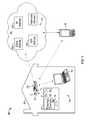
- FIG. 1is a diagram of a system for energy management in accordance with an example embodiment of the present disclosure.
- FIG. 2is a flow diagram of a method of providing a thermostat with a capability for connecting with and/or disconnecting from destination server(s) in accordance with an example embodiment of the present disclosure.
- a thermostat or other controller of the climate control systemmay be connected via the Internet with a utility demand response automation server.
- the connectionis typically through a homeowner's home area network.
- the homeownermay wish to employ a networking thermostat for additional purposes, e.g., to control the climate control system remotely by the user's smart phone, to communicate with an energy management service provider, to obtain weather reports, etc.
- the homeownermay not always wish to participate in demand response (DR) programs.
- DRdemand response
- a controllerfor controlling operation of a climate control system of a structure.
- the controllerincludes a processor, memory, and network interface configured to provide the controller with wireless network connectivity. Based on user input, the controller is connectable with each of a plurality of destination servers remote from the structure.
- a usercan selectively initiate, retain, or disable a controller's (e.g., thermostat's) connection to a demand response server while selectively initiating, retaining, or disabling connection(s) between the controller and other destination server(s) that provide other features and/or functions to and/or through the controller.
- a controller'se.g., thermostat's
- FIG. 1is a diagram of an exemplary system 20 for energy management embodying one or more aspects of the present disclosure.
- a controllere.g., a wireless-enabled thermostat 24
- the climate control systemmay be used to heat and/or cool the structure 28 through operation of various climate control components (not shown.)
- Such componentsmay include other or additional controller(s), e.g., a furnace controller, compressor controller, heat pump controller, etc.
- controllerse.g., a furnace controller, compressor controller, heat pump controller, etc.
- the thermostat 24includes a display device 60 , a processor 64 , memory 68 , and a network interface 72 .
- the network interface 72enables the thermostat 24 to receive information from external and/or remote location(s), e.g., for display on the display device 60 and/or for use in controlling the thermostat 24 .
- the network interface 72may be a wireless LAN/modem network interface.
- the network interface 72may provide access point (AP) capability.
- APaccess point
- Various embodimentsalso may include at least some wired connections. In a given connection, the network interface 72 provides a binary MAC number for identifying the thermostat 24 and provides Transport Control Protocol and Internet Protocol (TCP/IP) for accessing an internet URL.
- TCP/IPTransport Control Protocol and Internet Protocol
- the thermostat 24also includes user input means 76 that may include, e.g., button(s), key(s), manually operable switch(es), a touch pad, etc.
- the thermostat display device 60is capable, e.g., of displaying user-specified information such as weather forecast information and/or temperature overrides, which may be received from an Internet website and/or server external from the thermostat 24 .
- the processor 64may be configured to periodically request a connection via the network interface 72 to a server in an external location and/or to a wide-area network 40 , e.g., the Internet and/or cellular network(s), for accessing a website and retrieving user-specified information.
- An access point/router 32is provided in a local network 36 , which in the present example embodiment is a user's home network.
- the access point/router 32provides wireless access by the thermostat 24 through the home network 36 to the wide-area network 40 .
- the thermostat 24is wirelessly connectable, e.g., through the access point/router 32 , with a plurality of remote servers 44 , including a plurality of destination servers 48 a - 48 c referred to collectively by reference number 48 .
- destination serveris used herein and in the claims to refer to a server that may provide a particular capability, feature, and/or function to the thermostat 24 and that has a network address pre-designated in the system 20 for provision to the thermostat 24 and whereby the thermostat 24 may connect with that server.
- the destination server (“EMS server”) 48 amay provide energy management services in relation to the structure climate control system and thermostat 24 , to a user, e.g., an owner of the structure 28 who establishes a user profile with the provider of the energy management services.
- the usermay wish to establish a user profile, e.g., so that specific energy-related information might be retrieved and stored in memory in an external location, e.g., on or through the EMS server 48 a .
- Various energy management servicescould be provided, e.g., via the thermostat 24 , a computer 52 in the home network 36 and/or through one or more remote user devices 56 , e.g., a smart phone.
- User device(s) 56may include (without limitation) mobile device(s) such as an I-Pad®, a cellular or mobile phone, a smart phone such as a Blackberry®, an Android® device, an I-Phone®, etc., that can communicate using wireless communication, including but not limited to Wi-Fi, 802.11-based, WiMAX, Bluetooth, Zigbee, 3G, 4G, subscriber-based wireless, PCS, EDGE, and/or other wireless communication means, or any combination thereof.
- mobile device(s)such as an I-Pad®, a cellular or mobile phone, a smart phone such as a Blackberry®, an Android® device, an I-Phone®, etc.
- wireless communicationincluding but not limited to Wi-Fi, 802.11-based, WiMAX, Bluetooth, Zigbee, 3G, 4G, subscriber-based wireless, PCS, EDGE, and/or other wireless communication means, or any combination thereof.
- the energy providermay make the destination server (“DR server”) 48 b available to provide the thermostat 24 with demand response (DR) capability.
- the DR server 48 bmay be operable by the energy provider to transmit DR event information to the thermostat 24 when periodically polled by the thermostat 24 .
- the thermostat 24may automatically adjust its energy settings to adjust energy consumption in the structure 28 .
- the DR server 48 bmay make DR event information available to energy management services users through the EMS server 48 a .
- the thermostat 24may connect with and/or through the EMS server 48 a to be provided with DR event information from the DR server 48 b.
- the destination server (“W server”) 48 cmay provide current weather information.
- the thermostat 24may be connected with the W server 48 c to obtain and display such information, e.g., as further described below.
- a usermay selectively initiate and/or terminate connection by the thermostat 24 with each destination server 48 individually.
- other or additional types of destination servers 48could be selectively connected with the thermostat 24 in accordance with various implementations of the disclosure, to provide other or additional information, features and/or functionality to the thermostat 24 .
- a thermostatmay be selectively connectable with more than three, or fewer than three, destination servers 48 .
- a homeownermay wish to employ a networking thermostat for various purposes, e.g., to participate in demand response programs, engage in energy management through an energy management services provider, receive weather information, etc.
- Such features and/or functionsmay be made available by and/or through servers such as the various destination servers 48 .
- a usermay selectively cause the thermostat 24 to connect with and/or disconnect from any given destination server 48 .
- the thermostat 24may operate, e.g., as a TCP/IP client relative to one or more destination server(s) 48 with which it is connected.
- Such connections by the thermostat 24 with destination server(s) 48may be on an intermittent basis, e.g., where the thermostat 24 periodically polls a given destination server 48 for connection with the given server 48 and the given server 48 expects to communicate with the thermostat 24 at predefined times.
- the thermostat 24may, e.g., periodically poll the DR server 48 b and receive demand response event information and participate in DR events when the user has chosen to connect the thermostat 24 with the DR server 48 b .
- the usermay provide input, as further described below, to the thermostat 24 to cause the thermostat 24 to send a disconnect message to the DR server 48 b.
- the thermostat input means 76includes one or more switches whereby the user may selectively cause the thermostat 24 to connect with one or more destination servers 48 .
- one or more manual switchesare provided whereby a user may select one or both of two options, e.g., obtaining energy management services and/or participating in DR events.
- the thermostat 24connects with the EMS server 48 a and/or with the DR server 48 b .
- a menuis displayed on the display device 60 that includes a plurality of IP addresses, and/or descriptors for such addresses, for selection therefrom by the user. The user may activate a touch screen or other input means 76 to select from the menu an IP address of a destination server 48 with which the thermostat 24 is to connect or from which the thermostat 24 is to disconnect.
- the thermostat 24may be configured to prioritize communications with the selected destination servers 48 . For example, where the thermostat 24 is connected with the DR server 48 b and also with the EMS server 48 a while the thermostat 24 is participating in a DR event, the thermostat 24 may poll the DR server 48 b more frequently than it polls the EMS server 48 a.
- thermostat 24may be operative as “soft” access point(s) through which the thermostat 24 may obtain user selections of destination server(s) 48 and/or connect with destination server(s) 48 .
- Client software and destination server addresses for demand response and for other or additional destination server-provided features and/or functionsmay reside in various locations, e.g., in the thermostat 24 , the access point/router 32 , the computer 52 , remote user device 56 , a destination server 48 , in the cloud (i.e., distributed over various computing devices in the Internet 40 ,) etc.
- a thermostatmay be configured to selectively connect with and disconnect from destination servers in accordance with some implementations of the disclosure, where no touch screen, keyboard, buttons or other thermostat user interface is needed.
- a software applicationmay be accessible, e.g., on or through a smart phone, tablet or other remote user device 56 , the computer 52 , etc. whereby the user may select between or among destination servers 48 for connection with or disconnection from the thermostat 24 .
- One example method of providing a thermostat with a capability for connecting with and/or disconnecting from destination server(s)is indicated generally in FIG. 2 by reference number 100 .
- a userdownloads or otherwise accesses a software application on a user device, e.g., the local computer 52 , smart phone or other remote user device 56 , etc., that has a user interface.
- the software applicationdisplays a menu on the user interface of the user device. The menu provides a list, e.g., of thermostat features and/or functions that may be made available through destination servers.
- the userselects, via the user interface, one or more of the features and/or functions.
- the user devicesends the user selections to the thermostat, e.g., by sending IP address(es) of destination server(s) corresponding to the selected feature(s) and/or function(s).
- the thermostatconnects with one or more destination servers corresponding to the user's selection, and in some embodiments may disconnect from any destination server corresponding to any feature and/or function that was not selected by the user.
- a usermay be provided with capability to enter and change preferences for connecting a thermostat with one or more destination servers.
- a usermay enter or change such preferences via a user device and send the new and/or changed preferences via a remote access command to a server, which may be a destination server.
- the servermay store the new and/or changed preferences and send them to the thermostat, which connects and/or disconnects with destination server(s) in accordance with the preferences.
- a connected networked thermostat with demand response capabilityallows a user to selectively turn on or off the demand response capability at the thermostat or via the network while retaining other connected functionality that the user may wish to retain.
- controlcan be provided over connected functionality on a user's network without disruption, as expected by the user, while allowing the user, e.g., to opt out of participation in a demand response program or other unwanted connected functionality.
- userscan tailor access as desired to energy management and/or demand response on their home networks.
- exemplary embodimentsinclude a thermostat or other controller having the ability to connect to two or more servers each for a specific function or purpose. The thermostat also has the ability to disable connection to one or more of the two or more servers as a function of a selection made by the user, e.g., to opt out of a demand response or reduction program offered by a utility or utility provider.
- Example embodimentsare provided so that this disclosure will be thorough, and will fully convey the scope to those who are skilled in the art. Numerous specific details are set forth such as examples of specific components, devices, and methods, to provide a thorough understanding of embodiments of the present disclosure. It will be apparent to those skilled in the art that specific details need not be employed, that example embodiments may be embodied in many different forms, and that neither should be construed to limit the scope of the disclosure. In some example embodiments, well-known processes, well-known device structures, and well-known technologies are not described in detail.
- parameter Xmay have a range of values from about A to about Z.
- disclosure of two or more ranges of values for a parametersubsume all possible combination of ranges for the value that might be claimed using endpoints of the disclosed ranges.
- parameter Xis exemplified herein to have values in the range of 1-10, or 2-9, or 3-8, it is also envisioned that Parameter X may have other ranges of values including 1-9, 1-8, 1-3, 1-2, 2-10, 2-8, 2-3, 3-10, and 3-9.
- the term “about” as used herein when modifying a quantity of an ingredient or reactant of the invention or employedrefers to variation in the numerical quantity that can happen through typical measuring and handling procedures used, for example, when making concentrates or solutions in the real world through inadvertent error in these procedures; through differences in the manufacture, source, or purity of the ingredients employed to make the compositions or carry out the methods; and the like.
- the term “about”also encompasses amounts that differ due to different equilibrium conditions for a composition resulting from a particular initial mixture. Whether or not modified by the term “about,” the claims include equivalents to the quantities.
- first, second, third, etc.may be used herein to describe various elements, components, regions, layers and/or sections, these elements, components, regions, layers and/or sections should not be limited by these terms. These terms may be only used to distinguish one element, component, region, layer or section from another region, layer or section. Terms such as “first,” “second,” and other numerical terms when used herein do not imply a sequence or order unless clearly indicated by the context. Thus, a first element, component, region, layer or section discussed below could be termed a second element, component, region, layer or section without departing from the teachings of the example embodiments.
- Spatially relative termssuch as “inner,” “outer,” “beneath,” “below,” “lower,” “above,” “upper” and the like, may be used herein for ease of description to describe one element or feature's relationship to another element(s) or feature(s) as illustrated in the figures. Spatially relative terms may be intended to encompass different orientations of the device in use or operation in addition to the orientation depicted in the figures. For example, if the device in the figures is turned over, elements described as “below” or “beneath” other elements or features would then be oriented “above” the other elements or features. Thus, the example term “below” can encompass both an orientation of above and below. The device may be otherwise oriented (rotated 90 degrees or at other orientations) and the spatially relative descriptors used herein interpreted accordingly.
Landscapes
- Engineering & Computer Science (AREA)
- General Engineering & Computer Science (AREA)
- Chemical & Material Sciences (AREA)
- Mechanical Engineering (AREA)
- Combustion & Propulsion (AREA)
- Signal Processing (AREA)
- Automation & Control Theory (AREA)
- Physics & Mathematics (AREA)
- Computer Networks & Wireless Communication (AREA)
- Human Computer Interaction (AREA)
- Fuzzy Systems (AREA)
- Mathematical Physics (AREA)
- General Physics & Mathematics (AREA)
- Computing Systems (AREA)
- Quality & Reliability (AREA)
- Manufacturing & Machinery (AREA)
- Telephonic Communication Services (AREA)
Abstract
Description
Claims (19)
Priority Applications (4)
| Application Number | Priority Date | Filing Date | Title |
|---|---|---|---|
| US14/159,330US9568205B2 (en) | 2014-01-20 | 2014-01-20 | Selectively connecting a climate control system controller with more than one destination server |
| CN201510028948.2ACN104793582B (en) | 2014-01-20 | 2015-01-20 | It is selectively connected atmosphere control system controller and more than one destination server |
| CN201520038939.7UCN204347591U (en) | 2014-01-20 | 2015-01-20 | For controlling atmosphere control system controller and the thermostat of the operation of the atmosphere control system of buildings |
| US15/431,040US10209692B2 (en) | 2014-01-20 | 2017-02-13 | Selectively connecting a climate control system controller with more than one destination server |
Applications Claiming Priority (1)
| Application Number | Priority Date | Filing Date | Title |
|---|---|---|---|
| US14/159,330US9568205B2 (en) | 2014-01-20 | 2014-01-20 | Selectively connecting a climate control system controller with more than one destination server |
Related Child Applications (1)
| Application Number | Title | Priority Date | Filing Date |
|---|---|---|---|
| US15/431,040Continuation-In-PartUS10209692B2 (en) | 2014-01-20 | 2017-02-13 | Selectively connecting a climate control system controller with more than one destination server |
Publications (2)
| Publication Number | Publication Date |
|---|---|
| US20150204558A1 US20150204558A1 (en) | 2015-07-23 |
| US9568205B2true US9568205B2 (en) | 2017-02-14 |
Family
ID=53230849
Family Applications (1)
| Application Number | Title | Priority Date | Filing Date |
|---|---|---|---|
| US14/159,330Active2034-12-27US9568205B2 (en) | 2014-01-20 | 2014-01-20 | Selectively connecting a climate control system controller with more than one destination server |
Country Status (2)
| Country | Link |
|---|---|
| US (1) | US9568205B2 (en) |
| CN (2) | CN204347591U (en) |
Families Citing this family (32)
| Publication number | Priority date | Publication date | Assignee | Title |
|---|---|---|---|---|
| US9568205B2 (en)* | 2014-01-20 | 2017-02-14 | Emerson Electric Co. | Selectively connecting a climate control system controller with more than one destination server |
| US10209692B2 (en) | 2014-01-20 | 2019-02-19 | Emerson Electric Co. | Selectively connecting a climate control system controller with more than one destination server |
| US20150369508A1 (en)* | 2014-06-24 | 2015-12-24 | Howard Rosen | Method and Apparatus Providing Safety Improvement for Thermostat Devices That Provide Remote Control Features |
| US9152737B1 (en)* | 2014-11-26 | 2015-10-06 | Sense Labs, Inc. | Providing notifications to a user |
| US10175276B2 (en) | 2014-11-26 | 2019-01-08 | Sense Labs, Inc. | Identifying and categorizing power consumption with disaggregation |
| US9800762B2 (en)* | 2015-03-03 | 2017-10-24 | Ricoh Company, Ltd. | Non-transitory computer-readable information recording medium, information processing apparatus, and communications system |
| AU2016257459B2 (en) | 2015-05-04 | 2019-04-04 | Johnson Controls Technology Company | Multi-function home control system with control system hub and remote sensors |
| US11216020B2 (en) | 2015-05-04 | 2022-01-04 | Johnson Controls Tyco IP Holdings LLP | Mountable touch thermostat using transparent screen technology |
| US10677484B2 (en) | 2015-05-04 | 2020-06-09 | Johnson Controls Technology Company | User control device and multi-function home control system |
| US10410300B2 (en) | 2015-09-11 | 2019-09-10 | Johnson Controls Technology Company | Thermostat with occupancy detection based on social media event data |
| US10760809B2 (en) | 2015-09-11 | 2020-09-01 | Johnson Controls Technology Company | Thermostat with mode settings for multiple zones |
| US10546472B2 (en) | 2015-10-28 | 2020-01-28 | Johnson Controls Technology Company | Thermostat with direction handoff features |
| US11277893B2 (en) | 2015-10-28 | 2022-03-15 | Johnson Controls Technology Company | Thermostat with area light system and occupancy sensor |
| US10345781B2 (en) | 2015-10-28 | 2019-07-09 | Johnson Controls Technology Company | Multi-function thermostat with health monitoring features |
| US10655881B2 (en) | 2015-10-28 | 2020-05-19 | Johnson Controls Technology Company | Thermostat with halo light system and emergency directions |
| US10318266B2 (en) | 2015-11-25 | 2019-06-11 | Johnson Controls Technology Company | Modular multi-function thermostat |
| CN112929247A (en)* | 2015-12-22 | 2021-06-08 | 小米科技有限责任公司 | Method, device and system for accessing intelligent household electrical appliance to multiple servers |
| CN105450779B (en)* | 2015-12-31 | 2019-05-21 | 九阳股份有限公司 | The method of one household appliance connection multiserver |
| US10941951B2 (en) | 2016-07-27 | 2021-03-09 | Johnson Controls Technology Company | Systems and methods for temperature and humidity control |
| US9699529B1 (en) | 2017-02-22 | 2017-07-04 | Sense Labs, Inc. | Identifying device state changes using power data and network data |
| US10750252B2 (en) | 2017-02-22 | 2020-08-18 | Sense Labs, Inc. | Identifying device state changes using power data and network data |
| US10458669B2 (en) | 2017-03-29 | 2019-10-29 | Johnson Controls Technology Company | Thermostat with interactive installation features |
| WO2018191510A1 (en) | 2017-04-14 | 2018-10-18 | Johnson Controls Technology Company | Multi-function thermostat with air quality display |
| US11162698B2 (en) | 2017-04-14 | 2021-11-02 | Johnson Controls Tyco IP Holdings LLP | Thermostat with exhaust fan control for air quality and humidity control |
| US11131474B2 (en) | 2018-03-09 | 2021-09-28 | Johnson Controls Tyco IP Holdings LLP | Thermostat with user interface features |
| CN108803737A (en)* | 2018-06-15 | 2018-11-13 | 温岭市志创网络科技有限公司 | A kind of intelligent building air monitoring system based on big data |
| US10740691B2 (en) | 2018-10-02 | 2020-08-11 | Sense Labs, Inc. | Identifying devices connected to a smart plug |
| US11107390B2 (en) | 2018-12-21 | 2021-08-31 | Johnson Controls Technology Company | Display device with halo |
| CN113272596A (en) | 2019-01-07 | 2021-08-17 | 布罗恩-努托恩有限责任公司 | System and method for controlling indoor air quality |
| USD944731S1 (en) | 2019-07-11 | 2022-03-01 | Sense Labs, Inc. | Electrical current sensor |
| US11768228B2 (en) | 2019-07-11 | 2023-09-26 | Sense Labs, Inc. | Current transformer with calibration information |
| US20250257892A1 (en)* | 2022-04-27 | 2025-08-14 | Broan-Nutone Llc | Indoor air quality management apparatus and method |
Citations (26)
| Publication number | Priority date | Publication date | Assignee | Title |
|---|---|---|---|---|
| US6598056B1 (en) | 1999-02-12 | 2003-07-22 | Honeywell International Inc. | Remotely accessible building information system |
| WO2004044753A1 (en) | 2002-11-12 | 2004-05-27 | Zetera Corporation | Data storage devices having ip capable partitions |
| EP1587292A2 (en) | 2004-04-16 | 2005-10-19 | Broadcom Corporation | Remote configuration and control of local devices via a broadband access gateway |
| US20060283965A1 (en)* | 2005-06-20 | 2006-12-21 | Mueller Carl J | Thermostat capable of displaying recieved information |
| US20090099699A1 (en)* | 2007-08-03 | 2009-04-16 | John Douglas Steinberg | System and method for using a network of thermostats as tool to verify peak demand reduction |
| US20090254971A1 (en) | 1999-10-27 | 2009-10-08 | Pinpoint, Incorporated | Secure data interchange |
| US20100063644A1 (en) | 2008-09-08 | 2010-03-11 | Microsoft Corporation | Energy cost reduction and ad delivery |
| US20100083356A1 (en) | 2008-09-29 | 2010-04-01 | Andrew Steckley | System and method for intelligent automated remote management of electromechanical devices |
| US20100282857A1 (en)* | 2009-05-11 | 2010-11-11 | Ecofactor, Inc. | System, method and apparatus for dynamically variable compressor delay in thermostat to reduce energy consumption |
| US20110015802A1 (en)* | 2009-07-20 | 2011-01-20 | Imes Kevin R | Energy management system and method |
| US20110061014A1 (en) | 2008-02-01 | 2011-03-10 | Energyhub | Interfacing to resource consumption management devices |
| US20110063126A1 (en) | 2008-02-01 | 2011-03-17 | Energyhub | Communications hub for resource consumption management |
| US20110202181A1 (en)* | 2010-02-12 | 2011-08-18 | Enphase Energy, Inc. | Method and apparatus for smart climate control |
| US20110290893A1 (en)* | 2010-05-26 | 2011-12-01 | John Douglas Steinberg | System and method for using a mobile electronic device to optimize an energy management system |
| US8091795B1 (en) | 2008-07-15 | 2012-01-10 | Home Automation, Inc. | Intelligent thermostat device with automatic adaptable energy conservation based on real-time energy pricing |
| US20120065783A1 (en) | 2010-09-14 | 2012-03-15 | Nest Labs, Inc. | Thermodynamic modeling for enclosures |
| US20120069131A1 (en) | 2010-05-28 | 2012-03-22 | Abelow Daniel H | Reality alternate |
| US20120179297A1 (en)* | 2011-01-11 | 2012-07-12 | Jaesik Jung | Apparatus, method for controlling one or more outdoor devices, and air conditioning system having the same |
| US20120232969A1 (en)* | 2010-12-31 | 2012-09-13 | Nest Labs, Inc. | Systems and methods for updating climate control algorithms |
| US20120323393A1 (en)* | 2011-06-17 | 2012-12-20 | Raphael Imhof | Automated demand response system |
| US20130030589A1 (en) | 2011-06-30 | 2013-01-31 | Lutron Electronics Co., Inc. | Load Control Device Having Internet Connectivity |
| US20130090767A1 (en)* | 2011-10-07 | 2013-04-11 | Nest Labs, Inc. | Methods and graphical user interfaces for reporting performance information for an hvac system controlled by a self-programming network-connected thermostat |
| US20130095459A1 (en) | 2006-05-12 | 2013-04-18 | Bao Tran | Health monitoring system |
| US20130325997A1 (en) | 2010-11-19 | 2013-12-05 | Alektrona Corporation | Remote asset control systems and methods |
| US20140058567A1 (en)* | 2010-11-19 | 2014-02-27 | Nest Labs, Inc. | Hvac schedule establishment in an intelligent, network-connected thermostat |
| US20150195671A1 (en)* | 2012-06-29 | 2015-07-09 | Interdigital Patent Holdings, Inc. | Service-based discovery in networks |
Family Cites Families (6)
| Publication number | Priority date | Publication date | Assignee | Title |
|---|---|---|---|---|
| CN100369431C (en)* | 2004-06-30 | 2008-02-13 | 三洋电机株式会社 | Networkable appliance |
| US7606906B2 (en)* | 2005-10-28 | 2009-10-20 | International Business Machines Corporation | Bundling and sending work units to a server based on a weighted cost |
| US9778718B2 (en)* | 2009-02-13 | 2017-10-03 | Schneider Electric It Corporation | Power supply and data center control |
| CN101646054A (en)* | 2009-09-10 | 2010-02-10 | 中兴通讯股份有限公司 | System and method of IPTV terminal switched among a plurality of EPG servers |
| US8918219B2 (en)* | 2010-11-19 | 2014-12-23 | Google Inc. | User friendly interface for control unit |
| US9568205B2 (en)* | 2014-01-20 | 2017-02-14 | Emerson Electric Co. | Selectively connecting a climate control system controller with more than one destination server |
- 2014
- 2014-01-20USUS14/159,330patent/US9568205B2/enactiveActive
- 2015
- 2015-01-20CNCN201520038939.7Upatent/CN204347591U/ennot_activeExpired - Fee Related
- 2015-01-20CNCN201510028948.2Apatent/CN104793582B/ennot_activeExpired - Fee Related
Patent Citations (28)
| Publication number | Priority date | Publication date | Assignee | Title |
|---|---|---|---|---|
| US6598056B1 (en) | 1999-02-12 | 2003-07-22 | Honeywell International Inc. | Remotely accessible building information system |
| US20090254971A1 (en) | 1999-10-27 | 2009-10-08 | Pinpoint, Incorporated | Secure data interchange |
| US20130097664A1 (en) | 1999-10-27 | 2013-04-18 | Pinpoint, Incorporated | Secure data interchange |
| WO2004044753A1 (en) | 2002-11-12 | 2004-05-27 | Zetera Corporation | Data storage devices having ip capable partitions |
| EP1587292A2 (en) | 2004-04-16 | 2005-10-19 | Broadcom Corporation | Remote configuration and control of local devices via a broadband access gateway |
| US20060283965A1 (en)* | 2005-06-20 | 2006-12-21 | Mueller Carl J | Thermostat capable of displaying recieved information |
| US7434742B2 (en)* | 2005-06-20 | 2008-10-14 | Emerson Electric Co. | Thermostat capable of displaying received information |
| US20130095459A1 (en) | 2006-05-12 | 2013-04-18 | Bao Tran | Health monitoring system |
| US20090099699A1 (en)* | 2007-08-03 | 2009-04-16 | John Douglas Steinberg | System and method for using a network of thermostats as tool to verify peak demand reduction |
| US20110063126A1 (en) | 2008-02-01 | 2011-03-17 | Energyhub | Communications hub for resource consumption management |
| US20110061014A1 (en) | 2008-02-01 | 2011-03-10 | Energyhub | Interfacing to resource consumption management devices |
| US8091795B1 (en) | 2008-07-15 | 2012-01-10 | Home Automation, Inc. | Intelligent thermostat device with automatic adaptable energy conservation based on real-time energy pricing |
| US20100063644A1 (en) | 2008-09-08 | 2010-03-11 | Microsoft Corporation | Energy cost reduction and ad delivery |
| US20100083356A1 (en) | 2008-09-29 | 2010-04-01 | Andrew Steckley | System and method for intelligent automated remote management of electromechanical devices |
| US20100282857A1 (en)* | 2009-05-11 | 2010-11-11 | Ecofactor, Inc. | System, method and apparatus for dynamically variable compressor delay in thermostat to reduce energy consumption |
| US20110015802A1 (en)* | 2009-07-20 | 2011-01-20 | Imes Kevin R | Energy management system and method |
| US20110202181A1 (en)* | 2010-02-12 | 2011-08-18 | Enphase Energy, Inc. | Method and apparatus for smart climate control |
| US20110290893A1 (en)* | 2010-05-26 | 2011-12-01 | John Douglas Steinberg | System and method for using a mobile electronic device to optimize an energy management system |
| US20120069131A1 (en) | 2010-05-28 | 2012-03-22 | Abelow Daniel H | Reality alternate |
| US20120065783A1 (en) | 2010-09-14 | 2012-03-15 | Nest Labs, Inc. | Thermodynamic modeling for enclosures |
| US20130325997A1 (en) | 2010-11-19 | 2013-12-05 | Alektrona Corporation | Remote asset control systems and methods |
| US20140058567A1 (en)* | 2010-11-19 | 2014-02-27 | Nest Labs, Inc. | Hvac schedule establishment in an intelligent, network-connected thermostat |
| US20120232969A1 (en)* | 2010-12-31 | 2012-09-13 | Nest Labs, Inc. | Systems and methods for updating climate control algorithms |
| US20120179297A1 (en)* | 2011-01-11 | 2012-07-12 | Jaesik Jung | Apparatus, method for controlling one or more outdoor devices, and air conditioning system having the same |
| US20120323393A1 (en)* | 2011-06-17 | 2012-12-20 | Raphael Imhof | Automated demand response system |
| US20130030589A1 (en) | 2011-06-30 | 2013-01-31 | Lutron Electronics Co., Inc. | Load Control Device Having Internet Connectivity |
| US20130090767A1 (en)* | 2011-10-07 | 2013-04-11 | Nest Labs, Inc. | Methods and graphical user interfaces for reporting performance information for an hvac system controlled by a self-programming network-connected thermostat |
| US20150195671A1 (en)* | 2012-06-29 | 2015-07-09 | Interdigital Patent Holdings, Inc. | Service-based discovery in networks |
Also Published As
| Publication number | Publication date |
|---|---|
| CN104793582B (en) | 2019-06-14 |
| CN204347591U (en) | 2015-05-20 |
| CN104793582A (en) | 2015-07-22 |
| US20150204558A1 (en) | 2015-07-23 |
Similar Documents
| Publication | Publication Date | Title |
|---|---|---|
| US9568205B2 (en) | Selectively connecting a climate control system controller with more than one destination server | |
| US11650555B2 (en) | Bluetooth thermostat and hub | |
| US10386088B2 (en) | Efficient distribution of heating, ventilation and air conditioning functionality | |
| US8761050B2 (en) | Network integration system and method | |
| US10209692B2 (en) | Selectively connecting a climate control system controller with more than one destination server | |
| US20200036828A1 (en) | Networking systems, protocols, and methods for controlling target devices | |
| US20160274611A1 (en) | Smart electrical switch with engery metering capability | |
| US20170134182A1 (en) | Wireless Power Control, Metrics and Management | |
| US9964322B2 (en) | Controller set point adjustment based on outdoor temperature | |
| EP3117567B1 (en) | Apparatus and method for control of thermal appliances | |
| US12333889B2 (en) | Food preparation apparatus having a virtual data bus | |
| US10785097B2 (en) | Configuring interaction control in multi-controller network | |
| JP6544685B2 (en) | Control device, control method and control program | |
| JP2017033823A (en) | CONTROL DEVICE, ITS CONTROL METHOD, PROGRAM, AND CONTROL SYSTEM |
Legal Events
| Date | Code | Title | Description |
|---|---|---|---|
| AS | Assignment | Owner name:EMERSON ELECTRIC CO., MISSOURI Free format text:ASSIGNMENT OF ASSIGNORS INTEREST;ASSIGNORS:SARTAIN, JOHN M.;SIRAVURI, RISHI;REEL/FRAME:032006/0379 Effective date:20140103 | |
| STCF | Information on status: patent grant | Free format text:PATENTED CASE | |
| MAFP | Maintenance fee payment | Free format text:PAYMENT OF MAINTENANCE FEE, 4TH YEAR, LARGE ENTITY (ORIGINAL EVENT CODE: M1551); ENTITY STATUS OF PATENT OWNER: LARGE ENTITY Year of fee payment:4 | |
| AS | Assignment | Owner name:COPELAND COMFORT CONTROL LP, MISSOURI Free format text:SUPPLEMENTAL IP ASSIGNMENT AGREEMENT;ASSIGNOR:EMERSON ELECTRIC CO.;REEL/FRAME:063804/0611 Effective date:20230426 | |
| AS | Assignment | Owner name:ROYAL BANK OF CANADA, AS COLLATERAL AGENT, CANADA Free format text:SECURITY INTEREST;ASSIGNOR:COPELAND COMFORT CONTROL LP;REEL/FRAME:064278/0165 Effective date:20230531 Owner name:U.S. BANK TRUST COMPANY, NATIONAL ASSOCIATION, AS NOTES COLLATERAL AGENT, MINNESOTA Free format text:SECURITY INTEREST;ASSIGNOR:COPELAND COMFORT CONTROL LP;REEL/FRAME:064280/0333 Effective date:20230531 Owner name:WELLS FARGO BANK, NATIONAL ASSOCIATION, AS COLLATERAL AGENT, CALIFORNIA Free format text:SECURITY INTEREST;ASSIGNOR:COPELAND COMFORT CONTROL LP;REEL/FRAME:064286/0001 Effective date:20230531 | |
| AS | Assignment | Owner name:U.S. BANK TRUST COMPANY, NATIONAL ASSOCIATION, AS NOTES COLLATERAL AGENT, MINNESOTA Free format text:SECURITY INTEREST;ASSIGNOR:COPELAND COMFORT CONTROL LP;REEL/FRAME:068255/0466 Effective date:20240708 | |
| MAFP | Maintenance fee payment | Free format text:PAYMENT OF MAINTENANCE FEE, 8TH YEAR, LARGE ENTITY (ORIGINAL EVENT CODE: M1552); ENTITY STATUS OF PATENT OWNER: LARGE ENTITY Year of fee payment:8 |