US9567983B2 - Method for generation of power from intraluminal pressure changes - Google Patents
Method for generation of power from intraluminal pressure changesDownload PDFInfo
- Publication number
- US9567983B2 US9567983B2US12/315,631US31563108AUS9567983B2US 9567983 B2US9567983 B2US 9567983B2US 31563108 AUS31563108 AUS 31563108AUS 9567983 B2US9567983 B2US 9567983B2
- Authority
- US
- United States
- Prior art keywords
- intraluminal
- pressure change
- generator
- receiving structure
- operably coupled
- Prior art date
- Legal status (The legal status is an assumption and is not a legal conclusion. Google has not performed a legal analysis and makes no representation as to the accuracy of the status listed.)
- Expired - Fee Related, expires
Links
- 238000000034methodMethods0.000titleclaimsabstractdescription18
- 230000008859changeEffects0.000claimsabstractdescription164
- 239000012530fluidSubstances0.000claimsdescription31
- 239000012528membraneSubstances0.000claimsdescription31
- 230000008878couplingEffects0.000description27
- 238000010168coupling processMethods0.000description27
- 238000005859coupling reactionMethods0.000description27
- 229920001746electroactive polymerPolymers0.000description12
- 230000008569processEffects0.000description11
- 230000005294ferromagnetic effectEffects0.000description9
- 239000011800void materialSubstances0.000description8
- 238000006073displacement reactionMethods0.000description6
- -1polyethylenePolymers0.000description6
- 238000010248power generationMethods0.000description6
- XEEYBQQBJWHFJM-UHFFFAOYSA-NIronChemical compound[Fe]XEEYBQQBJWHFJM-UHFFFAOYSA-N0.000description4
- 239000004696Poly ether ether ketoneSubstances0.000description4
- 239000002202Polyethylene glycolSubstances0.000description4
- XLOMVQKBTHCTTD-UHFFFAOYSA-NZinc monoxideChemical compound[Zn]=OXLOMVQKBTHCTTD-UHFFFAOYSA-N0.000description4
- 230000008901benefitEffects0.000description4
- 229910052797bismuthInorganic materials0.000description4
- JCXGWMGPZLAOME-UHFFFAOYSA-Nbismuth atomChemical compound[Bi]JCXGWMGPZLAOME-UHFFFAOYSA-N0.000description4
- 239000013078crystalSubstances0.000description4
- 238000004146energy storageMethods0.000description4
- 229920002530polyetherether ketonePolymers0.000description4
- 229920001223polyethylene glycolPolymers0.000description4
- 229920000642polymerPolymers0.000description4
- 239000004065semiconductorSubstances0.000description4
- 238000005516engineering processMethods0.000description3
- WKBPZYKAUNRMKP-UHFFFAOYSA-N1-[2-(2,4-dichlorophenyl)pentyl]1,2,4-triazoleChemical compoundC=1C=C(Cl)C=C(Cl)C=1C(CCC)CN1C=NC=N1WKBPZYKAUNRMKP-UHFFFAOYSA-N0.000description2
- WUPHOULIZUERAE-UHFFFAOYSA-N3-(oxolan-2-yl)propanoic acidChemical compoundOC(=O)CCC1CCCO1WUPHOULIZUERAE-UHFFFAOYSA-N0.000description2
- JBRZTFJDHDCESZ-UHFFFAOYSA-NAsGaChemical compound[As]#[Ga]JBRZTFJDHDCESZ-UHFFFAOYSA-N0.000description2
- 102000008186CollagenHuman genes0.000description2
- 108010035532CollagenProteins0.000description2
- 229920002595Dielectric elastomerPolymers0.000description2
- 239000004593EpoxySubstances0.000description2
- 229910001218Gallium arsenideInorganic materials0.000description2
- 239000002033PVDF binderSubstances0.000description2
- 239000004698PolyethyleneSubstances0.000description2
- 239000004721Polyphenylene oxideSubstances0.000description2
- QXZUUHYBWMWJHK-UHFFFAOYSA-N[Co].[Ni]Chemical compound[Co].[Ni]QXZUUHYBWMWJHK-UHFFFAOYSA-N0.000description2
- 229910002113barium titanateInorganic materials0.000description2
- JRPBQTZRNDNNOP-UHFFFAOYSA-Nbarium titanateChemical compound[Ba+2].[Ba+2].[O-][Ti]([O-])([O-])[O-]JRPBQTZRNDNNOP-UHFFFAOYSA-N0.000description2
- 239000008280bloodSubstances0.000description2
- 210000004369bloodAnatomy0.000description2
- 229910052980cadmium sulfideInorganic materials0.000description2
- 239000000919ceramicSubstances0.000description2
- 229920001436collagenPolymers0.000description2
- 238000004590computer programMethods0.000description2
- 229920001940conductive polymerPolymers0.000description2
- 238000010586diagramMethods0.000description2
- 230000035487diastolic blood pressureEffects0.000description2
- NKZSPGSOXYXWQA-UHFFFAOYSA-Ndioxido(oxo)titanium;lead(2+)Chemical compound[Pb+2].[O-][Ti]([O-])=ONKZSPGSOXYXWQA-UHFFFAOYSA-N0.000description2
- 229910000154gallium phosphateInorganic materials0.000description2
- 239000000499gelSubstances0.000description2
- 238000003306harvestingMethods0.000description2
- 230000006698inductionEffects0.000description2
- 229910052500inorganic mineralInorganic materials0.000description2
- 229910052742ironInorganic materials0.000description2
- 229910052451lead zirconate titanateInorganic materials0.000description2
- HFGPZNIAWCZYJU-UHFFFAOYSA-Nlead zirconate titanateChemical compound[O-2].[O-2].[O-2].[O-2].[O-2].[Ti+4].[Zr+4].[Pb+2]HFGPZNIAWCZYJU-UHFFFAOYSA-N0.000description2
- 229910052744lithiumInorganic materials0.000description2
- GQYHUHYESMUTHG-UHFFFAOYSA-Nlithium niobateChemical compound[Li+].[O-][Nb](=O)=OGQYHUHYESMUTHG-UHFFFAOYSA-N0.000description2
- 230000005291magnetic effectEffects0.000description2
- 230000007246mechanismEffects0.000description2
- 239000002905metal composite materialSubstances0.000description2
- 239000011707mineralSubstances0.000description2
- 230000004048modificationEffects0.000description2
- 238000012986modificationMethods0.000description2
- 229920000728polyesterPolymers0.000description2
- 229920000570polyetherPolymers0.000description2
- 229920000573polyethylenePolymers0.000description2
- 229920000193polymethacrylatePolymers0.000description2
- 229920001296polysiloxanePolymers0.000description2
- 229920001343polytetrafluoroethylenePolymers0.000description2
- 229920002635polyurethanePolymers0.000description2
- 239000004814polyurethaneSubstances0.000description2
- 229920002981polyvinylidene fluoridePolymers0.000description2
- BITYAPCSNKJESK-UHFFFAOYSA-NpotassiosodiumChemical compound[Na].[K]BITYAPCSNKJESK-UHFFFAOYSA-N0.000description2
- LJCNRYVRMXRIQR-OLXYHTOASA-Lpotassium sodium L-tartrateChemical compound[Na+].[K+].[O-]C(=O)[C@H](O)[C@@H](O)C([O-])=OLJCNRYVRMXRIQR-OLXYHTOASA-L0.000description2
- UKDIAJWKFXFVFG-UHFFFAOYSA-Npotassium;oxido(dioxo)niobiumChemical compound[K+].[O-][Nb](=O)=OUKDIAJWKFXFVFG-UHFFFAOYSA-N0.000description2
- 239000010453quartzSubstances0.000description2
- 230000009467reductionEffects0.000description2
- 238000011160researchMethods0.000description2
- 230000004044responseEffects0.000description2
- 150000004756silanesChemical class0.000description2
- VYPSYNLAJGMNEJ-UHFFFAOYSA-Nsilicon dioxideInorganic materialsO=[Si]=OVYPSYNLAJGMNEJ-UHFFFAOYSA-N0.000description2
- 235000011006sodium potassium tartrateNutrition0.000description2
- XMVONEAAOPAGAO-UHFFFAOYSA-Nsodium tungstateChemical compound[Na+].[Na+].[O-][W]([O-])(=O)=OXMVONEAAOPAGAO-UHFFFAOYSA-N0.000description2
- 238000000638solvent extractionMethods0.000description2
- 230000035488systolic blood pressureEffects0.000description2
- 239000011031topazSubstances0.000description2
- 229910000218topaz groupInorganic materials0.000description2
- 229910000231tourmaline groupInorganic materials0.000description2
- 238000012546transferMethods0.000description2
- 230000007704transitionEffects0.000description2
- 239000011787zinc oxideSubstances0.000description2
- 229910000859α-FeInorganic materials0.000description2
- 244000122871Caryocar villosumSpecies0.000description1
- 239000000227bioadhesiveSubstances0.000description1
- 230000036772blood pressureEffects0.000description1
- 210000005242cardiac chamberAnatomy0.000description1
- 238000012512characterization methodMethods0.000description1
- 238000010276constructionMethods0.000description1
- 238000013479data entryMethods0.000description1
- 230000003205diastolic effectEffects0.000description1
- 230000000694effectsEffects0.000description1
- 210000002615epidermisAnatomy0.000description1
- 230000006870functionEffects0.000description1
- 238000001727in vivoMethods0.000description1
- 230000001939inductive effectEffects0.000description1
- 210000004072lungAnatomy0.000description1
- 239000000463materialSubstances0.000description1
- 239000003607modifierSubstances0.000description1
- 230000000241respiratory effectEffects0.000description1
- 239000008279solSubstances0.000description1
- 239000000126substanceSubstances0.000description1
- 239000002023woodSubstances0.000description1
Images


Classifications
- F—MECHANICAL ENGINEERING; LIGHTING; HEATING; WEAPONS; BLASTING
- F03—MACHINES OR ENGINES FOR LIQUIDS; WIND, SPRING, OR WEIGHT MOTORS; PRODUCING MECHANICAL POWER OR A REACTIVE PROPULSIVE THRUST, NOT OTHERWISE PROVIDED FOR
- F03G—SPRING, WEIGHT, INERTIA OR LIKE MOTORS; MECHANICAL-POWER PRODUCING DEVICES OR MECHANISMS, NOT OTHERWISE PROVIDED FOR OR USING ENERGY SOURCES NOT OTHERWISE PROVIDED FOR
- F03G7/00—Mechanical-power-producing mechanisms, not otherwise provided for or using energy sources not otherwise provided for
- F03G7/04—Mechanical-power-producing mechanisms, not otherwise provided for or using energy sources not otherwise provided for using pressure differences or thermal differences occurring in nature
Definitions
- Small scale generatorsfor generating energy at levels suitable for powering devices which are in vivo or ex vivo to a human or animal are described. Such generators may be implanted in luminal structures so as to extract power from intraluminal pressure changes.
- FIG. 1shows a high-level block diagram of an intraluminal power generation system.
- FIG. 2shows a high-level block diagram of an intraluminal power generation system.
- FIG. 3is a high-level logic flowchart of a process.
- FIG. 4is a high-level logic flowchart of a process.
- FIG. 5is a high-level logic flowchart of a process.
- FIG. 6is a high-level logic flowchart of a process.
- FIG. 7is a high-level logic flowchart of a process.
- FIG. 8is a high-level logic flowchart of a process.
- FIG. 9is a high-level logic flowchart of a process.
- FIG. 10is a high-level logic flowchart of a process.
- FIG. 11is a high-level logic flowchart of a process.
- FIG. 12is a high-level logic flowchart of a process.
- FIG. 13is a high-level logic flowchart of a process.
- FIGS. 1 and 2illustrate example environments in which one or more technologies may be implemented.
- An intraluminal power generation systemmay comprise an intraluminal generator 100 configured for disposal within an anatomical lumen 101 defined by a lumen wall 102 .
- the intraluminal generator 100may be configured to convert a varying intraluminal pressure change into energy (e.g. electrical energy, mechanical/elastic energy, chemical energy, thermal energy).
- the intraluminal generator 100may include an integrated pressure change receiving structure 103 A configured to receive a pressure change associated with a fluid pressure within the lumen 101 .
- a pressure change receiving structure 103 Bmay be operably coupled to the intraluminal generator 100 via a coupling 104 to transfer a received pressure from the pressure change receiving structure 103 B to the intraluminal generator 100 in a form which the intraluminal generator 100 may convert to energy.
- the intraluminal power generation systemmay comprise an energy storage apparatus 105 for storage of energy generated by the intraluminal generator 100 .
- the energy storage apparatus 105may be operably coupled to the intraluminal generator 100 by a coupling 106 .
- the intraluminal power generation systemmay comprise a power utilization device 107 which may use energy generated by the intraluminal generator 100 or stored in the energy storage apparatus 105 to carry out a desired function.
- the power utilization device 107may be operably coupled to the intraluminal generator 100 or an energy storage apparatus 105 by a coupling 108 .
- FIG. 2illustrates various spatial configurations of one or more components of an intraluminal power generation system.
- An intraluminal generator 100 disposed within in a first lumen 101 Amay be operably coupled to power utilization device 107 A disposed in the first lumen 101 A (e.g. in a distal relationship to the power utilization device 107 A).
- An intraluminal generator 100 disposed within in a first lumen 101 Amay be operably coupled to power utilization device 107 B disposed in a second lumen 101 B.
- An intraluminal generator 100 disposed within in a first lumen 101 Amay be operably coupled to an ex vivo power utilization device 107 C disposed outside the lumen or outside an epidermis layer 110 .
- FIG. 3illustrates an operational flow 300 representing example operations related to generating power from intraluminal pressure changes.
- discussion and explanationmay be provided with respect to the above-described examples of FIGS. 1 and 2 , and/or with respect to other examples and contexts.
- the operational flowsmay be executed in a number of other environments and contexts, and/or in modified versions of FIGS. 1 and 2 .
- the various operational flowsare presented in the sequence(s) illustrated, it should be understood that the various operations may be performed in other orders than those which are illustrated, or may be performed concurrently.
- Operation 310depicts receiving an intraluminal pressure change.
- a change in pressure within the lumen 101may be received by a pressure change receiving structure 103 .
- the pressure change receiving structure 103may receive a change in pressure through exposure of a surface of the pressure change receiving structure 103 to the luminal environment such that a change in the intraluminal pressure may exert a force on the pressure change receiving structure 103 thereby resulting in a deformation of the pressure change receiving structure 103 .
- Operation 320depicts converting the intraluminal pressure change into energy with an intraluminal generator.
- the change in pressuremay induce a movement and/or deformation of the pressure change receiving structure 103 which may be translated either directly (e.g. the intraluminal generator 100 comprises the pressure change receiving structure 103 A) or indirectly (e.g. the pressure change receiving structure 103 B is operably coupled to a generator) into energy either through the motion of the pressure change receiving structure 103 and/or the electrical properties of the materials comprising the pressure change receiving structure 103 .
- FIG. 4illustrates alternative embodiments of the example operational flow 300 of FIG. 3 .
- FIG. 4illustrates example embodiments where the receiving operation 310 may include at least one additional operation. Additional operations may include an operation 402 , an operation 404 and/or an operation 406 .
- Operation 402depicts receiving an intraluminal pressure change associated with an intraluminal fluid. For example, as shown in FIG. 1 , a change in pressure associated with a fluid flowing within lumen 101 may be received by the pressure change receiving structure 103 through physical contact of the fluid with a pressure receiving surface of the pressure change receiving structure 103 .
- Operation 404depicts receiving an intraluminal pressure change associated with a blood pressure change.
- a change in pressure associated with a transition between a diastolic and systolic state of the heart chambersmay induce a change in pressure in blood flowing within lumen 101 .
- the bloodmay exert a varying pressure on the pressure change receiving structure 103 .
- Operation 406depicts receiving an intraluminal pressure change associated with a respiratory pressure change.
- a change in pressure associated with a transition between inhalation and exhalation of the lungsmay induce a change in air pressure within a lumen 101 .
- the airmay exert a varying pressure on the pressure change receiving structure 103 .
- FIG. 5illustrates alternative embodiments of the example operational flow 300 of FIG. 3 .
- FIG. 5illustrates example embodiments where the receiving operation 310 may include at least one additional operation. Additional operations may include an operation 502 , an operation 504 , an operation 506 and/or an operation 508 .
- Operation 502depicts receiving an intraluminal pressure change with a pressure change receiving structure operably coupled to an intraluminal generator.
- intraluminal generator 100may be operably coupled to pressure change receiving structure 103 B via coupling 104 .
- the pressure change receiving structure 103 Bmay receive a change in pressure associated with a fluid in the lumen 101 and convert and/or transfer that pressure to the intraluminal generator 100 via coupling 104 in a form (e.g. mechanical force, hydraulic force, electromagnetic force) which the intraluminal generator 100 may convert into one or more forms of energy.
- a forme.g. mechanical force, hydraulic force, electromagnetic force
- Operation 504depicts receiving an intraluminal pressure change with a resilient structure operably coupled to an intraluminal generator.
- intraluminal generator 100may be operably coupled to pressure change receiving structure 103 B which may be a resilient structure capable of deforming elastically upon application of pressure by an intraluminal fluid and then returning to its original conformation upon a reduction of pressure by the intraluminal fluid.
- Operation 506depicts receiving an intraluminal pressure change with a resilient membrane structure operably coupled to an intraluminal generator.
- intraluminal generator 100may be operably coupled to a pressure change receiving structure 103 B including a resilient membrane structure.
- the resilient membrane structuremay include a membrane disposed over a free-space void thereby partitioning the free-space void from the luminal environment so as to provide a cavity for deformation of the membrane in response to the application of pressure by an intraluminal fluid.
- the interior of the free-space void defined by the membranemay be evacuated; (e.g. to approximate systolic pressure); pressurized (e.g.
- Operation 508depicts receiving an intraluminal pressure change with a resilient polymeric structure operably coupled to an intraluminal generator.
- intraluminal generator 100may be operably coupled to a pressure change receiving structure 103 B including a resilient polymeric structure.
- a resilient polymeric structuremay include, but is not limited to, polymethacrylate, polyethylene glycol (PEG), polyethylene, polyetheretherketone (PEEK), polytetrafluoroethylene (Teflon), epoxy (e.g. Epo-Tek 353ND) and the like.
- FIG. 6illustrates alternative embodiments of the example operational flow 300 of FIG. 5 .
- FIG. 6illustrates example embodiments where the receiving operation 502 may include at least one additional operation. Additional operations may include an operation 602 , an operation 604 , an operation 606 and/or an operation 608 .
- Operation 602depicts receiving an intraluminal pressure change with an elastomeric pressure change receiving structure operably coupled to an intraluminal generator.
- intraluminal generator 100may be operably coupled to a pressure change receiving structure 103 B including an elastomeric structure.
- An elastomeric structuremay include, but is not limited to, polymethyl silanes (e.g. those manufactured by NuSil Technologies), polymethyl siloxanes, polyurethane, polyether/polyester copolymers, and the like
- Operation 604depicts receiving an intraluminal pressure change with a pressure change receiving structure operably coupled to an intraluminal electroactive polymer generator.
- a pressure change receiving structure 103 Bmay be operably coupled to a intraluminal generator 100 including an electroactive polymer.
- the electroactive polymermay include at least one of a dielectric electroactive polymers (e.g. electrostrictive polymers, dielectric elastomers) and ionic electroactive polymers (e.g. conductive polymers, ionic polymer-metal composites, responsive gels, Bucky gel actuators).
- Operation 606depicts receiving an intraluminal pressure change with a pressure change receiving structure operably coupled to an intraluminal piezoelectric generator.
- a pressure change receiving structure 103 Bmay be operably coupled to a intraluminal generator 100 including a piezoelectric structure.
- the piezoelectric structuremay include at least one of a naturally occurring crystal (e.g. berlinite, quartz, Rochelle salt, topaz, and tourmaline-group minerals), a manufactured crystal (e.g. gallium orthophosphate, langasite), a manufactured ceramic (e.g.
- a polymere.g. polyvinylidene fluoride
- Operation 608depicts receiving an intraluminal pressure change with an intraluminal pressure change receiving structure operably coupled to an intraluminal piezoelectric semiconductor generator.
- a pressure change receiving structure 103 Bmay be operably coupled to a intraluminal generator 100 including a piezoelectric semiconductor (e.g. collagen, zinc oxide, bismuth silicone oxide, gallium arsenide, cadmium sulfide).
- a piezoelectric semiconductore.g. collagen, zinc oxide, bismuth silicone oxide, gallium arsenide, cadmium sulfide.
- FIG. 7illustrates alternative embodiments of the example operational flow 300 of FIG. 5 .
- FIG. 6illustrates example embodiments where the receiving operation 502 may include at least one additional operation. Additional operations may include an operation 702 , an operation 704 , an operation 706 and/or an operation 708 .
- Operation 702depicts receiving an intraluminal pressure change with a pressure change receiving structure operably coupled to an intraluminal microelectromechanical system (MEMS) generator.
- MEMSmicroelectromechanical system
- a pressure change receiving structure 103 Bmay be operably coupled to a intraluminal generator 100 including a MEMS generator.
- the MEMS generatormay include those described in “Multi-Watt Electric Power from a Microfabricated Permanent-Magnet Generator” by Das, et al.
- Operation 704depicts receiving an intraluminal pressure change with an intraluminal pressure change receiving structure operably coupled to a mechanical generator.
- a pressure change receiving structure 103 Bmay be operably coupled to a mechanical intraluminal generator 100 capable of converting motion of the pressure change receiving structure 103 B into mechanical energy.
- the intraluminal generator 100may include a piston, lever, spring, or rachet mechanism operably coupled to the pressure change receiving structure 103 B.
- Operation 706depicts receiving an intraluminal pressure change with an intraluminal pressure change receiving structure operably coupled to a ferromagnetic generator.
- a pressure change receiving structure 103 Bmay be operably coupled to a ferromagnetic intraluminal generator 100 .
- the ferromagnetic intraluminal generator 100may include a ferromagnetic (e.g. magnetized iron, nickel cobalt) portion which may be disposed proximate to an electrical circuit whereby motion of the pressure change receiving structure 103 B may affect an associated movement of the ferromagnetic portion, thereby inducing a current in the circuit via magnetic induction.
- ferromagnetice.g. magnetized iron, nickel cobalt
- Operation 708depicts receiving an intraluminal pressure change with an intraluminal pressure change receiving structure operably coupled to a fluid displacement generator.
- a pressure change receiving structure 103 Bmay be operably coupled to a fluid displacement intraluminal generator 100 .
- the fluid displacement intraluminal generator 100may be a pump (e.g. a positive displacement pump) including one or more pump rotors.
- the motion of the pressure change receiving structure 103 Amay rotate the one or more rotors within the intraluminal generator 100 thereby increasing a pressure of a fluid contained within an associated system (e.g. a hydraulic line).
- FIG. 8illustrates alternative embodiments of the example operational flow 300 of FIG. 5 .
- FIG. 8illustrates example embodiments where the receiving operation 520 may include at least one additional operation. Additional operations may include an operation 802 an operation 804 , and/or an operation 806 .
- Operation 802depicts receiving an intraluminal pressure change with a pressure change receiving structure operably coupled to an intraluminal generator by a mechanical coupling.
- pressure change receiving structure 103 Bmay be operably coupled to intraluminal generator 100 by a mechanical coupling 104 (e.g. a connecting shaft or wire, piston).
- Operation 804depicts receiving an intraluminal pressure change with a pressure change receiving structure operably coupled to an intraluminal generator by a fluid coupling.
- pressure change receiving structure 103 Bmay be operably coupled to intraluminal generator 100 by a fluid coupling 104 (e.g. fluid filled conduit, hydraulic line).
- Operation 806depicts receiving an intraluminal pressure change with a pressure change receiving structure operably coupled to an intraluminal generator by a cantilevered beam coupling.
- pressure change receiving structure 103 Bmay be operably coupled to intraluminal generator 100 by a cantilevered beam coupling 104 .
- the pressure change receiving structure 103 Bmay be disposed at an unsupported portion of the cantilevered beam coupling 104 and the intraluminal generator 100 connected at the supported portion of the beam.
- a movement of the pressure change receiving structure 103 Bmay impart a moment force at the connection point of the cantilevered beam coupling 104 with the intraluminal generator 100 .
- FIG. 9illustrates alternative embodiments of the example operational flow 300 of FIG. 5 .
- FIG. 9illustrates example embodiments where the receiving operation 520 may include at least one additional operation. Additional operations may include an operation 902 an operation 904 , and/or an operation 906 .
- Operation 902depicts receiving an intraluminal pressure change with a pressure change receiving structure operably coupled to an intraluminal generator by a trampoline coupling.
- pressure change receiving structure 103 Bmay be operably coupled to intraluminal generator 100 by a trampoline coupling 104 .
- a trampoline couplingmay include a membrane which may receive an intraluminal pressure change. An areal force applied to the membrane may result in a tension force at the rim of the membrane which may act on the generator.
- Operation 904depicts receiving an intraluminal pressure change with a pressure change receiving structure operably coupled to an intraluminal generator by a camshaft coupling.
- pressure change receiving structure 103 Bmay be operably coupled to intraluminal generator 100 by a camshaft coupling 104 .
- the pressure change receiving structure 103 Bmay be coupled to a first end of a camshaft coupling 104 .
- a movement of the pressure change receiving structure 103 Bmay cause the camshaft coupling 104 to rotate.
- the movements of the cams of the camshaft coupling 104may, in turn, move various portions of the intraluminal generator 100 (e.g. ferromagnetic portions) so as to generate energy.
- Operation 906depicts receiving an intraluminal pressure change with a pressure change receiving structure operably coupled to an intraluminal generator by a mechanical lever coupling.
- pressure change receiving structure 103 Bmay be operably coupled to intraluminal generator 100 by a mechanical lever coupling 104 .
- the pressure change receiving structure 103 Bmay be coupled to a first end of a mechanical lever coupling 104 and the intraluminal generator 100 may be coupled to a second end of the mechanical lever coupling 104 .
- a movement of the pressure change receiving structure 103 Bmay cause the first end of the mechanical lever coupling 104 to impart a corresponding movement in second end of the mechanical lever coupling 104 .
- the movement of the second end of the mechanical levermay be operably coupled to intraluminal generator 100 by a mechanical lever coupling.
- FIG. 10illustrates alternative embodiments of the example operational flow 300 of FIG. 3 .
- FIG. 10illustrates example embodiments where the converting operation 320 may include at least one additional operation. Additional operations may include an operation 1002 , an operation 1004 and/or an operation 1006 .
- Operation 1002depicts converting the intraluminal pressure change into energy with an intraluminal generator encircling at least a portion of an intraluminal circumference.
- the intraluminal generator 100may be configured in at least a partially ring-shaped manner such that it may be secured within the lumen 101 by contacting at least a portion of the lumen wall 102 while still permitting fluid flow through the lumen 101 .
- Operation 1004depicts converting the intraluminal pressure change into energy with an intraluminal generator coupled to a lumen wall.
- the intraluminal generator 100may be coupled to the lumen wall 102 via mechanical attachments such as hooks, barbs, anchors, via bioadhesives, via friction from a radially applied force, or similar methods.
- Operation 1006depicts converting the intraluminal pressure change into energy with an intraluminal generator moveable relative to a lumen wall.
- the intraluminal generator 100may be tethered to the lumen wall 102 so as to restrict axial movement along the length of the lumen 101 while permitting radial movement across the width of the lumen 101 .
- FIG. 11illustrates alternative embodiments of the example operational flow 300 of FIG. 3 .
- FIG. 11illustrates example embodiments where the converting operation 320 may include at least one additional operation. Additional operations may include an operation 1102 , an operation 1104 , and/or an operation 1106 .
- Operation 1102depicts converting the intraluminal pressure change into energy with an intraluminal generator having a resilient structure.
- intraluminal generator 100may comprise a pressure change receiving structure 103 A including a resilient structure capable of deforming elastically upon application of pressure by an intraluminal fluid and then returning to its original conformation upon a reduction of pressure by the intraluminal fluid.
- Operation 1104depicts converting the intraluminal pressure change into energy with an intraluminal generator having a resilient membrane.
- intraluminal generator 100may comprise a pressure change receiving structure 103 A including a resilient membrane structure.
- the resilient membrane structuremay include a membrane disposed over a free-space void thereby partitioning the free-space void from the luminal environment so as to provide a cavity for deformation of the membrane in response to the application of pressure by an intraluminal fluid.
- the interior of the free-space void defined by the membranemay be evacuated; (e.g. to approximate systolic pressure); pressurized (e.g.
- Operation 1106depicts converting the intraluminal pressure change into energy with an intraluminal generator having a resilient polymeric membrane.
- intraluminal generator 100may comprise a pressure change receiving structure 103 A including a resilient polymeric membrane structure.
- a resilient polymeric membrane structuremay include, but is not limited to, polymethacrylate membranes, polyethylene glycol (PEG) membranes, polyethylene membranes, polyetheretherketone (PEEK) membranes, polytetrafluoroethylene (Teflon) membranes, epoxy (e.g. Epo-Tek 353ND) membranes, and the like.
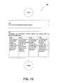
- FIG. 12illustrates alternative embodiments of the example operational flow 300 of FIG. 3 .
- FIG. 12illustrates example embodiments where the converting operation 320 may include at least one additional operation. Additional operations may include an operation 1202 , an operation 1204 , an operation 1206 , and/or an operation 1208 .
- Operation 1202depicts converting the intraluminal pressure change into energy with an intraluminal elastomeric generator.
- intraluminal generator 100may comprise a pressure change receiving structure 103 A including an elastomeric structure.
- An elastomeric structuremay include, but is not limited to, polymethyl silanes (e.g. those manufactured by NuSil Technologies), polymethyl siloxanes, polyurethane, polyether/polyester copolymers, and the like.
- Operation 1204depicts converting the intraluminal pressure change into energy with an intraluminal electroactive polymer generator.
- intraluminal generator 100may comprise a pressure change receiving structure 103 A including an electroactive polymer.
- the electroactive polymermay include at least one of a dielectric electroactive polymers (e.g. electrostrictive polymers, dielectric elastomers) and ionic electroactive polymers (e.g. conductive polymers, ionic polymer-metal composites, responsive gels, and Bucky gel actuators).
- a dielectric electroactive polymerse.g. electrostrictive polymers, dielectric elastomers
- ionic electroactive polymerse.g. conductive polymers, ionic polymer-metal composites, responsive gels, and Bucky gel actuators.
- Operation 1206depicts converting the intraluminal pressure change into energy with an intraluminal piezoelectric generator.
- intraluminal generator 100may comprise a pressure change receiving structure 103 A including a piezoelectric structure.
- the piezoelectric structuremay include at least one of a naturally occurring crystal (e.g. berlinite, quartz, Rochelle salt, topaz, and tourmaline-group minerals), a manufactured crystal (e.g. gallium orthophosphate, langasite), a manufactured ceramic (e.g.
- a polymere.g. polyvinylidene fluoride
- Operation 1208depicts converting the intraluminal pressure change into energy with an intraluminal piezoelectric semiconductor generator.
- intraluminal generator 100may include a pressure change receiving structure 103 A including a piezoelectric semiconductor (e.g. collagen, zinc oxide, bismuth silicone oxide, gallium arsenide, cadmium sulfide).
- a piezoelectric semiconductore.g. collagen, zinc oxide, bismuth silicone oxide, gallium arsenide, cadmium sulfide.
- FIG. 13illustrates alternative embodiments of the example operational flow 300 of FIG. 3 .
- FIG. 12illustrates example embodiments where the converting operation 320 may include at least one additional operation. Additional operations may include an operation 1302 , an operation 1304 , an operation 1306 , and/or an operation 1308 .
- Operation 1302depicts converting the intraluminal pressure change into energy with an intraluminal microelectromechanical system (MEMS) generator.
- intraluminal generator 100may be a MEMS generator.
- the MEMS generatormay include those described in “Multi-Watt Electric Power from a Microfabricated Permanent-Magnet Generator” by Das, et al.
- Operation 1304depicts converting the intraluminal pressure change into energy with a mechanical generator.
- intraluminal generator 100may be a mechanical generator capable of converting motion of the pressure change receiving structure 103 A into mechanical energy.
- the intraluminal generator 100may include a piston, lever, spring, or rachet mechanism operably coupled to the pressure change receiving structure 103 A.
- Operation 1306depicts converting the intraluminal pressure change into energy with a ferromagnetic generator.
- intraluminal generator 100may be a ferromagnetic generator.
- the pressure change receiving structure 103 Amay include a ferromagnetic (e.g. magnetized iron, nickel cobalt) portion which may be disposed proximate to an electrical circuit whereby motion of the pressure change receiving structure 103 A may induce a current in the circuit via magnetic induction.
- ferromagnetice.g. magnetized iron, nickel cobalt
- Operation 1308depicts converting the intraluminal pressure change into energy with a fluid displacement generator.
- intraluminal generator 100may be a pump (e.g. a positive displacement pump).
- the motion of the pressure change receiving structure 103 Amay rotate one or more rotors within the intraluminal generator 100 thereby increasing a pressure of a fluid contained within an associated system (e.g. a hydraulic line).
- any two components so associatedcan also be viewed as being “operably connected,” or “operably coupled,” to each other to achieve the desired functionality, and any two components capable of being so associated can also be viewed as being “operably couplable,” to each other to achieve the desired functionality.
- operably couplableinclude but are not limited to physically mateable and/or physically interacting components and/or wirelessly interactable and/or wirelessly interacting components and/or logically interacting and/or logically interactable components.
Landscapes
- Engineering & Computer Science (AREA)
- Chemical & Material Sciences (AREA)
- Combustion & Propulsion (AREA)
- Mechanical Engineering (AREA)
- General Engineering & Computer Science (AREA)
- External Artificial Organs (AREA)
Abstract
Description
Claims (3)
Priority Applications (6)
| Application Number | Priority Date | Filing Date | Title |
|---|---|---|---|
| US12/315,631US9567983B2 (en) | 2008-12-04 | 2008-12-04 | Method for generation of power from intraluminal pressure changes |
| US12/386,054US20100140958A1 (en) | 2008-12-04 | 2009-04-13 | Method for powering devices from intraluminal pressure changes |
| US12/455,669US9353733B2 (en) | 2008-12-04 | 2009-06-04 | Device and system for generation of power from intraluminal pressure changes |
| US12/462,789US9526418B2 (en) | 2008-12-04 | 2009-08-07 | Device for storage of intraluminally generated power |
| US12/462,796US9631610B2 (en) | 2008-12-04 | 2009-08-07 | System for powering devices from intraluminal pressure changes |
| US15/449,351US20170241411A1 (en) | 2008-12-04 | 2017-03-03 | System for powering devices from intraluminal pressure changes |
Applications Claiming Priority (1)
| Application Number | Priority Date | Filing Date | Title |
|---|---|---|---|
| US12/315,631US9567983B2 (en) | 2008-12-04 | 2008-12-04 | Method for generation of power from intraluminal pressure changes |
Related Parent Applications (2)
| Application Number | Title | Priority Date | Filing Date |
|---|---|---|---|
| US12/315,616Continuation-In-PartUS9759202B2 (en) | 2008-12-04 | 2008-12-04 | Method for generation of power from intraluminal pressure changes |
| US12/386,054Continuation-In-PartUS20100140958A1 (en) | 2008-12-04 | 2009-04-13 | Method for powering devices from intraluminal pressure changes |
Related Child Applications (3)
| Application Number | Title | Priority Date | Filing Date |
|---|---|---|---|
| US12/315,616Continuation-In-PartUS9759202B2 (en) | 2008-12-04 | 2008-12-04 | Method for generation of power from intraluminal pressure changes |
| US12/386,054Continuation-In-PartUS20100140958A1 (en) | 2008-12-04 | 2009-04-13 | Method for powering devices from intraluminal pressure changes |
| US12/462,796Continuation-In-PartUS9631610B2 (en) | 2008-12-04 | 2009-08-07 | System for powering devices from intraluminal pressure changes |
Publications (2)
| Publication Number | Publication Date |
|---|---|
| US20100140957A1 US20100140957A1 (en) | 2010-06-10 |
| US9567983B2true US9567983B2 (en) | 2017-02-14 |
Family
ID=42230240
Family Applications (1)
| Application Number | Title | Priority Date | Filing Date |
|---|---|---|---|
| US12/315,631Expired - Fee RelatedUS9567983B2 (en) | 2008-12-04 | 2008-12-04 | Method for generation of power from intraluminal pressure changes |
Country Status (1)
| Country | Link |
|---|---|
| US (1) | US9567983B2 (en) |
Families Citing this family (7)
| Publication number | Priority date | Publication date | Assignee | Title |
|---|---|---|---|---|
| US8600080B2 (en)* | 2008-01-14 | 2013-12-03 | Apple Inc. | Methods for communicating with electronic device accessories |
| US9631610B2 (en) | 2008-12-04 | 2017-04-25 | Deep Science, Llc | System for powering devices from intraluminal pressure changes |
| US9526418B2 (en) | 2008-12-04 | 2016-12-27 | Deep Science, Llc | Device for storage of intraluminally generated power |
| US20100140958A1 (en)* | 2008-12-04 | 2010-06-10 | Searete Llc, A Limited Liability Corporation Of The State Of Delaware | Method for powering devices from intraluminal pressure changes |
| US9759202B2 (en)* | 2008-12-04 | 2017-09-12 | Deep Science, Llc | Method for generation of power from intraluminal pressure changes |
| US9353733B2 (en) | 2008-12-04 | 2016-05-31 | Deep Science, Llc | Device and system for generation of power from intraluminal pressure changes |
| US9567983B2 (en) | 2008-12-04 | 2017-02-14 | Deep Science, Llc | Method for generation of power from intraluminal pressure changes |
Citations (122)
| Publication number | Priority date | Publication date | Assignee | Title |
|---|---|---|---|---|
| US3358690A (en) | 1964-11-18 | 1967-12-19 | Marvin M Cohen | Heart stimulator utilizing a pressuresensitive semiconductor |
| US3421512A (en) | 1965-12-15 | 1969-01-14 | Int Rectifier Corp | Implanted electrical device with biological power supply |
| US3456134A (en) | 1967-10-05 | 1969-07-15 | Us Health Education & Welfare | Piezoelectric energy converter for electronic implants |
| US3522811A (en) | 1969-02-13 | 1970-08-04 | Medtronic Inc | Implantable nerve stimulator and method of use |
| GB1220677A (en) | 1967-03-23 | 1971-01-27 | Plessey Co Ltd | Improvements in or relating to power-generating apparatus for incorporation in the human body |
| US3563245A (en) | 1968-03-15 | 1971-02-16 | Donald Neil Mclean | Biologically implantable and energized power supply |
| US3649615A (en) | 1968-07-08 | 1972-03-14 | Sumitomo Chemical Co | Phenyl-azo-naphthol dyes |
| US3659615A (en) | 1970-06-08 | 1972-05-02 | Carl C Enger | Encapsulated non-permeable piezoelectric powered pacesetter |
| US3861397A (en) | 1972-01-03 | 1975-01-21 | Siemens Ag | Implantable fuel cell |
| US3906960A (en) | 1973-02-27 | 1975-09-23 | Siegfried R Lehr | Medical energy converter |
| US3943936A (en) | 1970-09-21 | 1976-03-16 | Rasor Associates, Inc. | Self powered pacers and stimulators |
| US4140132A (en)* | 1978-03-23 | 1979-02-20 | Dahl Joseph D | Variable rate timer for a cardiac pacemaker |
| US4294891A (en) | 1980-03-12 | 1981-10-13 | The Montefiore Hospital Association Of Western Pennsylvania | Intermittently refuelable implantable bio-oxidant fuel cell |
| US4453537A (en) | 1981-08-04 | 1984-06-12 | Spitzer Daniel E | Apparatus for powering a body implant device |
| US4661107A (en) | 1986-07-21 | 1987-04-28 | Fink Irving E | Heart valve |
| US4690143A (en) | 1984-07-19 | 1987-09-01 | Cordis Corporation | Pacing lead with piezoelectric power generating means |
| US4798206A (en) | 1986-10-28 | 1989-01-17 | Telectronics N.V. | Implanted medical system including a self-powered sensing system |
| US5007927A (en) | 1989-10-24 | 1991-04-16 | Purdue Research Foundation | Muscle-powered cardiac assist device |
| US5010893A (en) | 1987-01-15 | 1991-04-30 | Siemens-Pacesetter, Inc. | Motion sensor for implanted medical device |
| US5154680A (en) | 1990-03-27 | 1992-10-13 | Rutgers University | Pressure waveform monitor |
| US5205286A (en) | 1991-07-24 | 1993-04-27 | Intermedics, Inc. | Subcutaneous electrical data port |
| US5344385A (en) | 1991-09-30 | 1994-09-06 | Thoratec Laboratories Corporation | Step-down skeletal muscle energy conversion system |
| US5348019A (en) | 1992-09-18 | 1994-09-20 | The Board Of Regents Of The University Of Oklahoma | Optical fiber pressure sensing catheter |
| US5411537A (en) | 1993-10-29 | 1995-05-02 | Intermedics, Inc. | Rechargeable biomedical battery powered devices with recharging and control system therefor |
| US5431694A (en) | 1992-08-18 | 1995-07-11 | Snaper; Alvin A. | Bio-operable power source |
| US5443504A (en) | 1991-09-30 | 1995-08-22 | Hill; John D. | Basic skeletal muscle energy conversion system |
| US5457624A (en) | 1994-06-13 | 1995-10-10 | Texas Instruments Incorporated | Efficient switched mode power converter circuit and method |
| US5535752A (en) | 1995-02-27 | 1996-07-16 | Medtronic, Inc. | Implantable capacitive absolute pressure and temperature monitor system |
| US5617876A (en) | 1994-09-19 | 1997-04-08 | Les Enterprises Laborie, Inc. | Apparatus for examining the functioning of body structures comprising smooth muscle walls |
| US5626141A (en) | 1990-04-13 | 1997-05-06 | Takeda Engineering Consultant Inc. | Blood pressure measurement apparatus and associated method |
| US5690693A (en) | 1995-06-07 | 1997-11-25 | Sulzer Intermedics Inc. | Transcutaneous energy transmission circuit for implantable medical device |
| US5693952A (en) | 1995-12-18 | 1997-12-02 | Sulzer Intermedics Inc. | Optically controlled high-voltage switch for an implantable defibrillator |
| US5702431A (en) | 1995-06-07 | 1997-12-30 | Sulzer Intermedics Inc. | Enhanced transcutaneous recharging system for battery powered implantable medical device |
| US5713939A (en) | 1996-09-16 | 1998-02-03 | Sulzer Intermedics Inc. | Data communication system for control of transcutaneous energy transmission to an implantable medical device |
| US5715837A (en) | 1996-08-29 | 1998-02-10 | Light Sciences Limited Partnership | Transcutaneous electromagnetic energy transfer |
| US5734564A (en) | 1996-07-26 | 1998-03-31 | Lucent Technologies Inc. | High-efficiency switching power converter |
| US5745358A (en) | 1996-05-01 | 1998-04-28 | Compaq Computer Corporation | Variable-frequency converter with constant programmed delay |
| US5749909A (en) | 1996-11-07 | 1998-05-12 | Sulzer Intermedics Inc. | Transcutaneous energy coupling using piezoelectric device |
| US5764495A (en) | 1996-05-01 | 1998-06-09 | Compaq Computer Corporation | Variable-frequency variable-input-voltage converter with minimum frequency limit |
| US5810015A (en) | 1995-09-01 | 1998-09-22 | Strato/Infusaid, Inc. | Power supply for implantable device |
| US5823199A (en) | 1992-11-25 | 1998-10-20 | Scimed Life Systems, Inc. | In vivo mechanical energy source |
| GB2350302A (en) | 1999-05-26 | 2000-11-29 | Demetriou Demetrios | Implanted power generator |
| US6164284A (en) | 1997-02-26 | 2000-12-26 | Schulman; Joseph H. | System of implantable devices for monitoring and/or affecting body parameters |
| US6268161B1 (en) | 1997-09-30 | 2001-07-31 | M-Biotech, Inc. | Biosensor |
| US6291900B1 (en) | 1997-09-15 | 2001-09-18 | General Electric Company | Electrical energy management for manually powered devices |
| US20020028999A1 (en) | 2000-07-22 | 2002-03-07 | Biotronik Mess-Und Therapiegeraete Gmbh & Co. | Implantable measuring device, particularly a pressure measuring device for determining the intracardial or intraluminal blood pressure |
| US6409674B1 (en) | 1998-09-24 | 2002-06-25 | Data Sciences International, Inc. | Implantable sensor with wireless communication |
| US6432050B1 (en) | 1997-12-30 | 2002-08-13 | Remon Medical Technologies Ltd. | Implantable acoustic bio-sensing system and method |
| US6475750B1 (en) | 1999-05-11 | 2002-11-05 | M-Biotech, Inc. | Glucose biosensor |
| US6580177B1 (en) | 1999-06-01 | 2003-06-17 | Continuum Control Corporation | Electrical power extraction from mechanical disturbances |
| US6589184B2 (en) | 2001-08-31 | 2003-07-08 | St. Jude Medical Ab | Implantable intravascular pressure determining device and method |
| US20030158584A1 (en) | 2002-02-19 | 2003-08-21 | Cates Adam W | Chronically-implanted device for sensing and therapy |
| US6638231B2 (en) | 2000-12-18 | 2003-10-28 | Biosense, Inc. | Implantable telemetric medical sensor and method |
| US6682490B2 (en) | 2001-12-03 | 2004-01-27 | The Cleveland Clinic Foundation | Apparatus and method for monitoring a condition inside a body cavity |
| US20040021322A1 (en) | 2002-07-31 | 2004-02-05 | Arie Ariav | Method and apparatus for body generation of electrical energy |
| US20040039242A1 (en) | 2002-04-02 | 2004-02-26 | Seedling Enterprises, Llc | Apparatus and methods using visible light for debilitating and/or killing microorganisms within the body |
| US6711423B2 (en) | 1998-08-26 | 2004-03-23 | Sensors For Medicine And Science, Inc. | Optical-based sensing devices |
| US20040078027A1 (en) | 2002-07-03 | 2004-04-22 | Yehoshua Shachar | Method and apparatus for piezoelectric layer-wise pump and valve for use in local administration of biological response modifiers and therapeutic agents |
| US20040158294A1 (en) | 2003-02-12 | 2004-08-12 | Medtronic, Inc. | Self-powered implantable element |
| US20040173220A1 (en)* | 2003-03-06 | 2004-09-09 | Harry Jason D. | Method and apparatus for improving human balance and gait and preventing foot injury |
| US20040193058A1 (en) | 2003-03-28 | 2004-09-30 | Valentino Montegrande | Blood pressure sensor apparatus |
| US20040204744A1 (en) | 2003-04-14 | 2004-10-14 | Remon Medicaltechnologies Ltd. | Apparatus and methods using acoustic telemetry for intrabody communications |
| US20040215279A1 (en) | 2003-04-25 | 2004-10-28 | Houben Richard P.M. | Implantable lead-based sensor powered by piezoelectric transformer |
| US6822343B2 (en) | 2002-02-28 | 2004-11-23 | Texas Instruments Incorporated | Generating electric power in response to activity of a biological system |
| US6829507B1 (en) | 1998-09-21 | 2004-12-07 | St. Jude Medical Ab | Apparatus for determining the actual status of a piezoelectric sensor in a medical implant |
| US6827682B2 (en) | 1999-06-23 | 2004-12-07 | Mogens Bugge | Implantable device for utilization of the hydraulic energy of the heart |
| US6860857B2 (en) | 2001-08-31 | 2005-03-01 | St. Jude Medical Ab | Implantable intravascular pressure determining device and method |
| US20050055061A1 (en) | 2003-09-08 | 2005-03-10 | Asher Holzer | Cardiac implant device |
| US20050080346A1 (en) | 2002-12-16 | 2005-04-14 | The Regents Of The University Of Michigan | Antenna stent device for wireless, intraluminal monitoring |
| US6895265B2 (en) | 2000-05-15 | 2005-05-17 | James H. Silver | Implantable sensor |
| US6953469B2 (en) | 2001-08-30 | 2005-10-11 | Ethicon, Inc, | Device and method for treating intraluminal tissue |
| US20050256549A1 (en) | 2002-10-09 | 2005-11-17 | Sirius Implantable Systems Ltd. | Micro-generator implant |
| US20050261563A1 (en)* | 2004-05-20 | 2005-11-24 | Peter Zhou | Transducer for embedded bio-sensor using body energy as a power source |
| US20060044078A1 (en) | 2004-08-24 | 2006-03-02 | Farrokh Ayazi | Capacitive vertical silicon bulk acoustic resonator |
| US7032600B2 (en) | 2003-01-16 | 2006-04-25 | Ntt Docomo, Inc. | Method and system for measuring a position, position measuring device, and an in vivo radio device |
| US20060152309A1 (en) | 2005-01-11 | 2006-07-13 | Mintchev Martin P | Magnetic levitation of intraluminal microelectronic capsule |
| US7081699B2 (en) | 2003-03-31 | 2006-07-25 | The Penn State Research Foundation | Thermoacoustic piezoelectric generator |
| US20060184206A1 (en) | 2005-02-15 | 2006-08-17 | Baker Rex M Iii | Implantable generating system |
| US20060217776A1 (en) | 2005-03-25 | 2006-09-28 | Robert White | Implantable cardiac motion powered piezoelectric energy source |
| US20060224214A1 (en) | 2005-04-04 | 2006-10-05 | Koller Levente L | Piezoelectrically stimulated article |
| US20070074731A1 (en) | 2005-10-05 | 2007-04-05 | Nth Tech Corporation | Bio-implantable energy harvester systems and methods thereof |
| US20070088402A1 (en) | 2005-10-18 | 2007-04-19 | Melvin David B | Muscle energy converter with smooth continuous tissue interface |
| US20070093875A1 (en) | 2005-10-24 | 2007-04-26 | Cardiac Pacemakers, Inc. | Implantable and rechargeable neural stimulator |
| US20070149885A1 (en) | 1994-09-02 | 2007-06-28 | Corl Paul D | Ultra miniature pressure sensor |
| US20070167988A1 (en) | 2006-01-13 | 2007-07-19 | Cernasov Andre N | Apparatus and method for supplying power to subcutaneously implanted devices |
| US7263894B2 (en) | 2004-06-07 | 2007-09-04 | Radi Medical Systems Ab | Sensor and guide wire assembly |
| US20070221233A1 (en) | 2005-12-28 | 2007-09-27 | Olympus Medical Systems Corp. | Body-insertable device system and in-vivo observation method |
| US7302856B2 (en) | 2003-05-07 | 2007-12-04 | California Institute Of Technology | Strain sensors based on nanowire piezoresistor wires and arrays |
| US20070293904A1 (en) | 2006-06-20 | 2007-12-20 | Daniel Gelbart | Self-powered resonant leadless pacemaker |
| US20080009687A1 (en) | 2003-06-06 | 2008-01-10 | Smith Joseph T | Coiled circuit bio-sensor |
| US20080021333A1 (en) | 2006-07-21 | 2008-01-24 | Cardiac Pacemakers, Inc. | Multiple sensor deployment |
| US20080082005A1 (en) | 2006-07-05 | 2008-04-03 | Stern David R | Method for Using a Wireless Pressure Sensor to Monitor Pressure Inside the Human Heart |
| US7362557B2 (en) | 2004-03-30 | 2008-04-22 | Continental Automotive Systems U.S. Inc. | Method, apparatus and article for bi-directional DC/DC power conversion |
| US20080132967A1 (en) | 2004-08-20 | 2008-06-05 | Cardiac Pacemakers, Inc. | Techniques for blood pressure measurement by implantable device |
| US20080172043A1 (en) | 2000-10-10 | 2008-07-17 | Microchips, Inc. | Microchip reservoir devices using wireless transmission of power and data |
| US7413547B1 (en) | 2004-11-08 | 2008-08-19 | Transoma Medical, Inc. | Reference sensor correction for implantable sensors |
| US20080212262A1 (en) | 2006-10-10 | 2008-09-04 | Micallef Joseph A | Piezoelectric Ultracapacitor |
| US7427265B1 (en) | 1998-02-23 | 2008-09-23 | Cardiometrix, Inc. | Endoluminal implant with therapeutic and diagnostic capability |
| US20080262562A1 (en) | 2007-04-17 | 2008-10-23 | Perpetuum Ltd. | Energy Harvester for an Implant Device |
| US20080281298A1 (en) | 2005-02-07 | 2008-11-13 | Andersen David R | Electronic support system for biological data sensor |
| US20090171413A1 (en) | 2007-08-31 | 2009-07-02 | Marco Zenati | Implantable device, system including same, and method utilizing same |
| US20090171448A1 (en) | 2007-04-27 | 2009-07-02 | Uri Eli | Implantable device with miniature rotating portion for energy harvesting |
| US20090270742A1 (en) | 2004-01-13 | 2009-10-29 | Remon Medical Technologies Ltd. | Devices for fixing a sensor in a lumen |
| US7616992B2 (en) | 2006-01-30 | 2009-11-10 | Medtronic, Inc. | Intravascular medical device |
| US20090281399A1 (en) | 2007-08-31 | 2009-11-12 | Keel Allen J | Standalone systemic arterial blood pressure monitoring device |
| US20090292335A1 (en) | 2008-05-22 | 2009-11-26 | Stichting Imec Nederland | Thermoelectric Generator for Implants and Embedded Devices |
| US20100010600A1 (en) | 2006-04-25 | 2010-01-14 | Tom Eriksson | piezoelectric sensor, a method for manufacturing a piezoelectric sensor and a medical implantable lead comprising such a piezoelectric sensor |
| US20100030043A1 (en) | 2008-07-30 | 2010-02-04 | Medtronic, Inc. | Implantable medical system including multiple sensing modules |
| US20100036450A1 (en) | 2007-06-17 | 2010-02-11 | Physical Logic Ag | Carbon Nano-tube Power Cell |
| US20100076517A1 (en) | 2008-09-23 | 2010-03-25 | Mir Imran | Energy harvesting mechanism for medical devices |
| US20100140956A1 (en) | 2008-12-04 | 2010-06-10 | Searete Llc. | Method for generation of power from intraluminal pressure changes |
| US20100140958A1 (en) | 2008-12-04 | 2010-06-10 | Searete Llc, A Limited Liability Corporation Of The State Of Delaware | Method for powering devices from intraluminal pressure changes |
| US20100140943A1 (en) | 2008-12-04 | 2010-06-10 | Searete Llc, A Limited Liability Corporation Of The State Of Delaware | Device for storage of intraluminally generated power |
| US20100141052A1 (en) | 2008-12-04 | 2010-06-10 | Searete Llc,A Limited Liability Corporation Of The State Of Delaware | System for powering devices from intraluminal pressure changes |
| US20100140959A1 (en) | 2008-12-04 | 2010-06-10 | Searete Llc, A Limited Liability Corporation Of The State Of Delaware | Device and system for generation of power from intraluminal pressure changes |
| US20100140957A1 (en) | 2008-12-04 | 2010-06-10 | Searete Llc | Method for generation of power from intraluminal pressure changes |
| US7777623B2 (en) | 2001-10-11 | 2010-08-17 | Enocean Gmbh | Wireless sensor system |
| US7798973B2 (en) | 2005-10-13 | 2010-09-21 | Cardiac Pacemakers, Inc. | Detection of hypovolemia using implantable medical device |
| US20100298720A1 (en) | 2009-04-16 | 2010-11-25 | Potkay Joseph Allen | In Situ Energy Harvesting Systems for Implanted Medical Devices |
| US20110062713A1 (en)* | 2008-01-14 | 2011-03-17 | Single Buoy Moorings Inc. | Wave energy absorber |
| US20110094314A1 (en) | 2007-08-27 | 2011-04-28 | Koninklijke Philips Electronics N.V. | Pressure sensor, sensor probe comprising a pressure sensor, medical apparatus comprising a sensor probe and a method of fabricating a sensor probe |
| US20110275947A1 (en) | 2007-01-04 | 2011-11-10 | Board Of Regents, The University Of Texas System | Cardiovascular power source for automatic implantable cardioverter defibrillators |
- 2008
- 2008-12-04USUS12/315,631patent/US9567983B2/ennot_activeExpired - Fee Related
Patent Citations (142)
| Publication number | Priority date | Publication date | Assignee | Title |
|---|---|---|---|---|
| US3358690A (en) | 1964-11-18 | 1967-12-19 | Marvin M Cohen | Heart stimulator utilizing a pressuresensitive semiconductor |
| US3421512A (en) | 1965-12-15 | 1969-01-14 | Int Rectifier Corp | Implanted electrical device with biological power supply |
| GB1220677A (en) | 1967-03-23 | 1971-01-27 | Plessey Co Ltd | Improvements in or relating to power-generating apparatus for incorporation in the human body |
| US3456134A (en) | 1967-10-05 | 1969-07-15 | Us Health Education & Welfare | Piezoelectric energy converter for electronic implants |
| US3563245A (en) | 1968-03-15 | 1971-02-16 | Donald Neil Mclean | Biologically implantable and energized power supply |
| US3649615A (en) | 1968-07-08 | 1972-03-14 | Sumitomo Chemical Co | Phenyl-azo-naphthol dyes |
| US3522811A (en) | 1969-02-13 | 1970-08-04 | Medtronic Inc | Implantable nerve stimulator and method of use |
| US3659615A (en) | 1970-06-08 | 1972-05-02 | Carl C Enger | Encapsulated non-permeable piezoelectric powered pacesetter |
| US3943936A (en) | 1970-09-21 | 1976-03-16 | Rasor Associates, Inc. | Self powered pacers and stimulators |
| US3861397A (en) | 1972-01-03 | 1975-01-21 | Siemens Ag | Implantable fuel cell |
| US3906960A (en) | 1973-02-27 | 1975-09-23 | Siegfried R Lehr | Medical energy converter |
| US4140132A (en)* | 1978-03-23 | 1979-02-20 | Dahl Joseph D | Variable rate timer for a cardiac pacemaker |
| US4294891A (en) | 1980-03-12 | 1981-10-13 | The Montefiore Hospital Association Of Western Pennsylvania | Intermittently refuelable implantable bio-oxidant fuel cell |
| US4453537A (en) | 1981-08-04 | 1984-06-12 | Spitzer Daniel E | Apparatus for powering a body implant device |
| US4690143A (en) | 1984-07-19 | 1987-09-01 | Cordis Corporation | Pacing lead with piezoelectric power generating means |
| US4661107A (en) | 1986-07-21 | 1987-04-28 | Fink Irving E | Heart valve |
| US4798206A (en) | 1986-10-28 | 1989-01-17 | Telectronics N.V. | Implanted medical system including a self-powered sensing system |
| US5010893A (en) | 1987-01-15 | 1991-04-30 | Siemens-Pacesetter, Inc. | Motion sensor for implanted medical device |
| US5007927A (en) | 1989-10-24 | 1991-04-16 | Purdue Research Foundation | Muscle-powered cardiac assist device |
| US5363855A (en) | 1990-03-27 | 1994-11-15 | Rutgers University | Pressure waveform monitor |
| US5154680A (en) | 1990-03-27 | 1992-10-13 | Rutgers University | Pressure waveform monitor |
| US5626141A (en) | 1990-04-13 | 1997-05-06 | Takeda Engineering Consultant Inc. | Blood pressure measurement apparatus and associated method |
| US5205286A (en) | 1991-07-24 | 1993-04-27 | Intermedics, Inc. | Subcutaneous electrical data port |
| US5984857A (en) | 1991-09-30 | 1999-11-16 | Thoratec Laboratories Corporation | Step-down skeletal muscle energy conversion system |
| US5344385A (en) | 1991-09-30 | 1994-09-06 | Thoratec Laboratories Corporation | Step-down skeletal muscle energy conversion system |
| US5443504A (en) | 1991-09-30 | 1995-08-22 | Hill; John D. | Basic skeletal muscle energy conversion system |
| US5701919A (en) | 1991-09-30 | 1997-12-30 | Thoratec Laboratories Corporation | Step-down skeletal muscle energy conversion system |
| US5653676A (en) | 1991-09-30 | 1997-08-05 | Thoratec Laboratories Corporation | Step-down skeletal muscle energy conversion method |
| US5431694A (en) | 1992-08-18 | 1995-07-11 | Snaper; Alvin A. | Bio-operable power source |
| US5348019A (en) | 1992-09-18 | 1994-09-20 | The Board Of Regents Of The University Of Oklahoma | Optical fiber pressure sensing catheter |
| US5823199A (en) | 1992-11-25 | 1998-10-20 | Scimed Life Systems, Inc. | In vivo mechanical energy source |
| US5411537A (en) | 1993-10-29 | 1995-05-02 | Intermedics, Inc. | Rechargeable biomedical battery powered devices with recharging and control system therefor |
| US5457624A (en) | 1994-06-13 | 1995-10-10 | Texas Instruments Incorporated | Efficient switched mode power converter circuit and method |
| US20070149885A1 (en) | 1994-09-02 | 2007-06-28 | Corl Paul D | Ultra miniature pressure sensor |
| US5617876A (en) | 1994-09-19 | 1997-04-08 | Les Enterprises Laborie, Inc. | Apparatus for examining the functioning of body structures comprising smooth muscle walls |
| US5535752A (en) | 1995-02-27 | 1996-07-16 | Medtronic, Inc. | Implantable capacitive absolute pressure and temperature monitor system |
| US5690693A (en) | 1995-06-07 | 1997-11-25 | Sulzer Intermedics Inc. | Transcutaneous energy transmission circuit for implantable medical device |
| US5702431A (en) | 1995-06-07 | 1997-12-30 | Sulzer Intermedics Inc. | Enhanced transcutaneous recharging system for battery powered implantable medical device |
| US5954058A (en) | 1995-09-01 | 1999-09-21 | Strato/Infusaid, Inc. | Power supply for implantable device |
| US5810015A (en) | 1995-09-01 | 1998-09-22 | Strato/Infusaid, Inc. | Power supply for implantable device |
| US5693952A (en) | 1995-12-18 | 1997-12-02 | Sulzer Intermedics Inc. | Optically controlled high-voltage switch for an implantable defibrillator |
| US5764495A (en) | 1996-05-01 | 1998-06-09 | Compaq Computer Corporation | Variable-frequency variable-input-voltage converter with minimum frequency limit |
| US5745358A (en) | 1996-05-01 | 1998-04-28 | Compaq Computer Corporation | Variable-frequency converter with constant programmed delay |
| US5734564A (en) | 1996-07-26 | 1998-03-31 | Lucent Technologies Inc. | High-efficiency switching power converter |
| US5715837A (en) | 1996-08-29 | 1998-02-10 | Light Sciences Limited Partnership | Transcutaneous electromagnetic energy transfer |
| US5713939A (en) | 1996-09-16 | 1998-02-03 | Sulzer Intermedics Inc. | Data communication system for control of transcutaneous energy transmission to an implantable medical device |
| US5749909A (en) | 1996-11-07 | 1998-05-12 | Sulzer Intermedics Inc. | Transcutaneous energy coupling using piezoelectric device |
| US6564807B1 (en) | 1997-02-26 | 2003-05-20 | Alfred E. Mann Foundation For Scientific Research | System of implantable devices for monitoring and/or affecting body parameters |
| US6164284A (en) | 1997-02-26 | 2000-12-26 | Schulman; Joseph H. | System of implantable devices for monitoring and/or affecting body parameters |
| US6291900B1 (en) | 1997-09-15 | 2001-09-18 | General Electric Company | Electrical energy management for manually powered devices |
| US6268161B1 (en) | 1997-09-30 | 2001-07-31 | M-Biotech, Inc. | Biosensor |
| US6432050B1 (en) | 1997-12-30 | 2002-08-13 | Remon Medical Technologies Ltd. | Implantable acoustic bio-sensing system and method |
| US7427265B1 (en) | 1998-02-23 | 2008-09-23 | Cardiometrix, Inc. | Endoluminal implant with therapeutic and diagnostic capability |
| US6711423B2 (en) | 1998-08-26 | 2004-03-23 | Sensors For Medicine And Science, Inc. | Optical-based sensing devices |
| US6829507B1 (en) | 1998-09-21 | 2004-12-07 | St. Jude Medical Ab | Apparatus for determining the actual status of a piezoelectric sensor in a medical implant |
| US6409674B1 (en) | 1998-09-24 | 2002-06-25 | Data Sciences International, Inc. | Implantable sensor with wireless communication |
| US6475750B1 (en) | 1999-05-11 | 2002-11-05 | M-Biotech, Inc. | Glucose biosensor |
| GB2350302A (en) | 1999-05-26 | 2000-11-29 | Demetriou Demetrios | Implanted power generator |
| US6580177B1 (en) | 1999-06-01 | 2003-06-17 | Continuum Control Corporation | Electrical power extraction from mechanical disturbances |
| US6827682B2 (en) | 1999-06-23 | 2004-12-07 | Mogens Bugge | Implantable device for utilization of the hydraulic energy of the heart |
| US6895265B2 (en) | 2000-05-15 | 2005-05-17 | James H. Silver | Implantable sensor |
| US7033322B2 (en) | 2000-05-15 | 2006-04-25 | Silver James H | Implantable sensor |
| US20020028999A1 (en) | 2000-07-22 | 2002-03-07 | Biotronik Mess-Und Therapiegeraete Gmbh & Co. | Implantable measuring device, particularly a pressure measuring device for determining the intracardial or intraluminal blood pressure |
| US6524256B2 (en) | 2000-07-22 | 2003-02-25 | Biotronik Mess-und Therapiegeraete GmbH & Co. Ingenieürbuero Berlin | Implantable measuring device, particularly a pressure measuring device for determining the intracardial or intraluminal blood pressure |
| US20080172043A1 (en) | 2000-10-10 | 2008-07-17 | Microchips, Inc. | Microchip reservoir devices using wireless transmission of power and data |
| US6638231B2 (en) | 2000-12-18 | 2003-10-28 | Biosense, Inc. | Implantable telemetric medical sensor and method |
| US6953469B2 (en) | 2001-08-30 | 2005-10-11 | Ethicon, Inc, | Device and method for treating intraluminal tissue |
| US6860857B2 (en) | 2001-08-31 | 2005-03-01 | St. Jude Medical Ab | Implantable intravascular pressure determining device and method |
| US6589184B2 (en) | 2001-08-31 | 2003-07-08 | St. Jude Medical Ab | Implantable intravascular pressure determining device and method |
| US7777623B2 (en) | 2001-10-11 | 2010-08-17 | Enocean Gmbh | Wireless sensor system |
| US6682490B2 (en) | 2001-12-03 | 2004-01-27 | The Cleveland Clinic Foundation | Apparatus and method for monitoring a condition inside a body cavity |
| US20030158584A1 (en) | 2002-02-19 | 2003-08-21 | Cates Adam W | Chronically-implanted device for sensing and therapy |
| US6822343B2 (en) | 2002-02-28 | 2004-11-23 | Texas Instruments Incorporated | Generating electric power in response to activity of a biological system |
| US20040039242A1 (en) | 2002-04-02 | 2004-02-26 | Seedling Enterprises, Llc | Apparatus and methods using visible light for debilitating and/or killing microorganisms within the body |
| US20040078027A1 (en) | 2002-07-03 | 2004-04-22 | Yehoshua Shachar | Method and apparatus for piezoelectric layer-wise pump and valve for use in local administration of biological response modifiers and therapeutic agents |
| US20040021322A1 (en) | 2002-07-31 | 2004-02-05 | Arie Ariav | Method and apparatus for body generation of electrical energy |
| US7081683B2 (en) | 2002-07-31 | 2006-07-25 | Arie Ariav | Method and apparatus for body generation of electrical energy |
| US20050256549A1 (en) | 2002-10-09 | 2005-11-17 | Sirius Implantable Systems Ltd. | Micro-generator implant |
| US20050080346A1 (en) | 2002-12-16 | 2005-04-14 | The Regents Of The University Of Michigan | Antenna stent device for wireless, intraluminal monitoring |
| US7452334B2 (en) | 2002-12-16 | 2008-11-18 | The Regents Of The University Of Michigan | Antenna stent device for wireless, intraluminal monitoring |
| US7032600B2 (en) | 2003-01-16 | 2006-04-25 | Ntt Docomo, Inc. | Method and system for measuring a position, position measuring device, and an in vivo radio device |
| US20040158294A1 (en) | 2003-02-12 | 2004-08-12 | Medtronic, Inc. | Self-powered implantable element |
| US20040173220A1 (en)* | 2003-03-06 | 2004-09-09 | Harry Jason D. | Method and apparatus for improving human balance and gait and preventing foot injury |
| US20040193058A1 (en) | 2003-03-28 | 2004-09-30 | Valentino Montegrande | Blood pressure sensor apparatus |
| US7081699B2 (en) | 2003-03-31 | 2006-07-25 | The Penn State Research Foundation | Thermoacoustic piezoelectric generator |
| US20040204744A1 (en) | 2003-04-14 | 2004-10-14 | Remon Medicaltechnologies Ltd. | Apparatus and methods using acoustic telemetry for intrabody communications |
| US20070142728A1 (en) | 2003-04-14 | 2007-06-21 | Avi Penner | Apparatus and methods using acoustic telemetry for intrabody communications |
| US20040215279A1 (en) | 2003-04-25 | 2004-10-28 | Houben Richard P.M. | Implantable lead-based sensor powered by piezoelectric transformer |
| US7302856B2 (en) | 2003-05-07 | 2007-12-04 | California Institute Of Technology | Strain sensors based on nanowire piezoresistor wires and arrays |
| US20080009687A1 (en) | 2003-06-06 | 2008-01-10 | Smith Joseph T | Coiled circuit bio-sensor |
| US20050055061A1 (en) | 2003-09-08 | 2005-03-10 | Asher Holzer | Cardiac implant device |
| US20090270742A1 (en) | 2004-01-13 | 2009-10-29 | Remon Medical Technologies Ltd. | Devices for fixing a sensor in a lumen |
| US7362557B2 (en) | 2004-03-30 | 2008-04-22 | Continental Automotive Systems U.S. Inc. | Method, apparatus and article for bi-directional DC/DC power conversion |
| US20050261563A1 (en)* | 2004-05-20 | 2005-11-24 | Peter Zhou | Transducer for embedded bio-sensor using body energy as a power source |
| US7241266B2 (en)* | 2004-05-20 | 2007-07-10 | Digital Angel Corporation | Transducer for embedded bio-sensor using body energy as a power source |
| US7263894B2 (en) | 2004-06-07 | 2007-09-04 | Radi Medical Systems Ab | Sensor and guide wire assembly |
| US20080132967A1 (en) | 2004-08-20 | 2008-06-05 | Cardiac Pacemakers, Inc. | Techniques for blood pressure measurement by implantable device |
| US20060044078A1 (en) | 2004-08-24 | 2006-03-02 | Farrokh Ayazi | Capacitive vertical silicon bulk acoustic resonator |
| US7413547B1 (en) | 2004-11-08 | 2008-08-19 | Transoma Medical, Inc. | Reference sensor correction for implantable sensors |
| US20060152309A1 (en) | 2005-01-11 | 2006-07-13 | Mintchev Martin P | Magnetic levitation of intraluminal microelectronic capsule |
| US20080281298A1 (en) | 2005-02-07 | 2008-11-13 | Andersen David R | Electronic support system for biological data sensor |
| US7729767B2 (en) | 2005-02-15 | 2010-06-01 | Baker Iii Rex M | Implantable generating system |
| US20060184206A1 (en) | 2005-02-15 | 2006-08-17 | Baker Rex M Iii | Implantable generating system |
| US7729768B2 (en) | 2005-03-25 | 2010-06-01 | Proteus Biomedical, Inc. | Implantable cardiac motion powered piezoelectric energy source |
| US20100228312A1 (en) | 2005-03-25 | 2010-09-09 | Robert White | Implantable Cardiac Motion Powered Piezoelectric Energy Source |
| US20060217776A1 (en) | 2005-03-25 | 2006-09-28 | Robert White | Implantable cardiac motion powered piezoelectric energy source |
| US20060224214A1 (en) | 2005-04-04 | 2006-10-05 | Koller Levente L | Piezoelectrically stimulated article |
| US7424325B2 (en) | 2005-04-04 | 2008-09-09 | Levente Lajos Koller | Piezoelectrically stimulated article |
| US20070074731A1 (en) | 2005-10-05 | 2007-04-05 | Nth Tech Corporation | Bio-implantable energy harvester systems and methods thereof |
| US7798973B2 (en) | 2005-10-13 | 2010-09-21 | Cardiac Pacemakers, Inc. | Detection of hypovolemia using implantable medical device |
| US20070088402A1 (en) | 2005-10-18 | 2007-04-19 | Melvin David B | Muscle energy converter with smooth continuous tissue interface |
| US7715918B2 (en) | 2005-10-18 | 2010-05-11 | University Of Cincinnati | Muscle energy converter with smooth continuous tissue interface |
| US7616990B2 (en) | 2005-10-24 | 2009-11-10 | Cardiac Pacemakers, Inc. | Implantable and rechargeable neural stimulator |
| US20070093875A1 (en) | 2005-10-24 | 2007-04-26 | Cardiac Pacemakers, Inc. | Implantable and rechargeable neural stimulator |
| US20100049275A1 (en) | 2005-10-24 | 2010-02-25 | Abhi Chavan | Implantable and rechargeable neural stimulator |
| US20070221233A1 (en) | 2005-12-28 | 2007-09-27 | Olympus Medical Systems Corp. | Body-insertable device system and in-vivo observation method |
| US20070167988A1 (en) | 2006-01-13 | 2007-07-19 | Cernasov Andre N | Apparatus and method for supplying power to subcutaneously implanted devices |
| US7616992B2 (en) | 2006-01-30 | 2009-11-10 | Medtronic, Inc. | Intravascular medical device |
| US20100010600A1 (en) | 2006-04-25 | 2010-01-14 | Tom Eriksson | piezoelectric sensor, a method for manufacturing a piezoelectric sensor and a medical implantable lead comprising such a piezoelectric sensor |
| US20070293904A1 (en) | 2006-06-20 | 2007-12-20 | Daniel Gelbart | Self-powered resonant leadless pacemaker |
| US20080082005A1 (en) | 2006-07-05 | 2008-04-03 | Stern David R | Method for Using a Wireless Pressure Sensor to Monitor Pressure Inside the Human Heart |
| US20080021333A1 (en) | 2006-07-21 | 2008-01-24 | Cardiac Pacemakers, Inc. | Multiple sensor deployment |
| US7859171B2 (en) | 2006-10-10 | 2010-12-28 | Micallef Joseph A | Piezoelectric ultracapacitor |
| US20080212262A1 (en) | 2006-10-10 | 2008-09-04 | Micallef Joseph A | Piezoelectric Ultracapacitor |
| US20110275947A1 (en) | 2007-01-04 | 2011-11-10 | Board Of Regents, The University Of Texas System | Cardiovascular power source for automatic implantable cardioverter defibrillators |
| US20080262562A1 (en) | 2007-04-17 | 2008-10-23 | Perpetuum Ltd. | Energy Harvester for an Implant Device |
| US20090171448A1 (en) | 2007-04-27 | 2009-07-02 | Uri Eli | Implantable device with miniature rotating portion for energy harvesting |
| US20100036450A1 (en) | 2007-06-17 | 2010-02-11 | Physical Logic Ag | Carbon Nano-tube Power Cell |
| US20110094314A1 (en) | 2007-08-27 | 2011-04-28 | Koninklijke Philips Electronics N.V. | Pressure sensor, sensor probe comprising a pressure sensor, medical apparatus comprising a sensor probe and a method of fabricating a sensor probe |
| US20090281399A1 (en) | 2007-08-31 | 2009-11-12 | Keel Allen J | Standalone systemic arterial blood pressure monitoring device |
| US20090171413A1 (en) | 2007-08-31 | 2009-07-02 | Marco Zenati | Implantable device, system including same, and method utilizing same |
| US20110062713A1 (en)* | 2008-01-14 | 2011-03-17 | Single Buoy Moorings Inc. | Wave energy absorber |
| US20090292335A1 (en) | 2008-05-22 | 2009-11-26 | Stichting Imec Nederland | Thermoelectric Generator for Implants and Embedded Devices |
| US20100030043A1 (en) | 2008-07-30 | 2010-02-04 | Medtronic, Inc. | Implantable medical system including multiple sensing modules |
| US20100076517A1 (en) | 2008-09-23 | 2010-03-25 | Mir Imran | Energy harvesting mechanism for medical devices |
| US20100140943A1 (en) | 2008-12-04 | 2010-06-10 | Searete Llc, A Limited Liability Corporation Of The State Of Delaware | Device for storage of intraluminally generated power |
| US20100141052A1 (en) | 2008-12-04 | 2010-06-10 | Searete Llc,A Limited Liability Corporation Of The State Of Delaware | System for powering devices from intraluminal pressure changes |
| US20100140959A1 (en) | 2008-12-04 | 2010-06-10 | Searete Llc, A Limited Liability Corporation Of The State Of Delaware | Device and system for generation of power from intraluminal pressure changes |
| US20100140957A1 (en) | 2008-12-04 | 2010-06-10 | Searete Llc | Method for generation of power from intraluminal pressure changes |
| US20100140958A1 (en) | 2008-12-04 | 2010-06-10 | Searete Llc, A Limited Liability Corporation Of The State Of Delaware | Method for powering devices from intraluminal pressure changes |
| US20100140956A1 (en) | 2008-12-04 | 2010-06-10 | Searete Llc. | Method for generation of power from intraluminal pressure changes |
| US20100298720A1 (en) | 2009-04-16 | 2010-11-25 | Potkay Joseph Allen | In Situ Energy Harvesting Systems for Implanted Medical Devices |
Non-Patent Citations (3)
| Title |
|---|
| Franklin Hadley, Goodbye Wires . . . , MIT News, Jun. 7, 2007, Publisher: http://web.mit.edu/newsoffice/2007/wireless-0607.html, Published in: US. |
| Kara Gavin, Zapping the Heart Back Into Rhythm, University of Michigan Health Minute, Jun. 2, 2005, Published in: Ann Arbor, MI. |
| Zhong Lin Wang, Self-Powered Nanotech: Nanosize Machines Need Still Tinier Power Plants, Scientific American Magazine, Dec. 16, 2007, pp. 82-87, Published in: US. |
Also Published As
| Publication number | Publication date |
|---|---|
| US20100140957A1 (en) | 2010-06-10 |
Similar Documents
| Publication | Publication Date | Title |
|---|---|---|
| US9567983B2 (en) | Method for generation of power from intraluminal pressure changes | |
| US9353733B2 (en) | Device and system for generation of power from intraluminal pressure changes | |
| Dong et al. | Vibration‐energy‐harvesting system: transduction mechanisms, frequency tuning techniques, and biomechanical applications | |
| Iqbal et al. | Vibration‐based piezoelectric, electromagnetic, and hybrid energy harvesters for microsystems applications: a contributed review | |
| Salauddin et al. | Miniaturized springless hybrid nanogenerator for powering portable and wearable electronic devices from human-body-induced vibration | |
| Invernizzi et al. | Energy harvesting from human motion: materials and techniques | |
| Lagomarsini et al. | Hybrid piezoelectric–electrostatic generators for wearable energy harvesting applications | |
| Li et al. | The mechanism for large-volume fluid pumping via reversible snap-through of dielectric elastomer | |
| JP5509350B2 (en) | Electroactive polymer generator powered by the environment | |
| Minami et al. | Development of enhanced piezoelectric energy harvester induced by human motion | |
| Mao et al. | Design and characterization of a soft dielectric elastomer peristaltic pump driven by electromechanical load | |
| WO2009091807A1 (en) | Apparatus for in vivo energy harvesting | |
| CN108348222A (en) | Medical Probes for Ultrasound Imaging | |
| CN111726026A (en) | A composite energy harvester and wearable electronic device | |
| Sherrit | The physical acoustics of energy harvesting | |
| JP2012533274A (en) | Small smart material actuator and energy capture device | |
| Elnemr et al. | Multi-transduction-mechanism technology, an emerging approach to enhance sensor performance | |
| Kwon et al. | Piezoelectric and electromagnetic hybrid energy harvester using two cantilevers for frequency up-conversion | |
| US9759202B2 (en) | Method for generation of power from intraluminal pressure changes | |
| McKay et al. | Realizing the potential of dielectric elastomer generators | |
| EP3472874A1 (en) | Friction control device and method | |
| Walters et al. | Artificial heartbeat: design and fabrication of a biologically inspired pump | |
| CN115088179A (en) | Energy collector and method for collecting energy | |
| US20120290043A1 (en) | Implanted energy source | |
| Ye et al. | Robust control of dielectric elastomer diaphragm actuator for replicating human pulse |
Legal Events
| Date | Code | Title | Description |
|---|---|---|---|
| AS | Assignment | Owner name:SEARETE LLC,WASHINGTON Free format text:ASSIGNMENT OF ASSIGNORS INTEREST;ASSIGNORS:HYDE, RODERICK A.;ISHIKAWA, MURIEL Y.;LEUTHARDT, ERIC C.;AND OTHERS;SIGNING DATES FROM 20081218 TO 20090308;REEL/FRAME:022402/0118 Owner name:SEARETE LLC, WASHINGTON Free format text:ASSIGNMENT OF ASSIGNORS INTEREST;ASSIGNORS:HYDE, RODERICK A.;ISHIKAWA, MURIEL Y.;LEUTHARDT, ERIC C.;AND OTHERS;SIGNING DATES FROM 20081218 TO 20090308;REEL/FRAME:022402/0118 | |
| AS | Assignment | Owner name:DEEP SCIENCE, LLC, WASHINGTON Free format text:ASSIGNMENT OF ASSIGNORS INTEREST;ASSIGNOR:SEARETE LLC;REEL/FRAME:037535/0584 Effective date:20160113 | |
| FEPP | Fee payment procedure | Free format text:PAYOR NUMBER ASSIGNED (ORIGINAL EVENT CODE: ASPN); ENTITY STATUS OF PATENT OWNER: LARGE ENTITY | |
| STCF | Information on status: patent grant | Free format text:PATENTED CASE | |
| FEPP | Fee payment procedure | Free format text:MAINTENANCE FEE REMINDER MAILED (ORIGINAL EVENT CODE: REM.); ENTITY STATUS OF PATENT OWNER: LARGE ENTITY | |
| LAPS | Lapse for failure to pay maintenance fees | Free format text:PATENT EXPIRED FOR FAILURE TO PAY MAINTENANCE FEES (ORIGINAL EVENT CODE: EXP.); ENTITY STATUS OF PATENT OWNER: LARGE ENTITY | |
| STCH | Information on status: patent discontinuation | Free format text:PATENT EXPIRED DUE TO NONPAYMENT OF MAINTENANCE FEES UNDER 37 CFR 1.362 | |
| FP | Lapsed due to failure to pay maintenance fee | Effective date:20210214 | |
| AS | Assignment | Owner name:ENTERPRISE SCIENCE FUND, LLC, WASHINGTON Free format text:ASSIGNMENT OF ASSIGNORS INTEREST;ASSIGNOR:DEEP SCIENCE LLC;REEL/FRAME:064943/0001 Effective date:20230601 |