US9566957B2 - Disk brake hub assembly - Google Patents
Disk brake hub assemblyDownload PDFInfo
- Publication number
- US9566957B2 US9566957B2US13/436,422US201213436422AUS9566957B2US 9566957 B2US9566957 B2US 9566957B2US 201213436422 AUS201213436422 AUS 201213436422AUS 9566957 B2US9566957 B2US 9566957B2
- Authority
- US
- United States
- Prior art keywords
- brake
- hub
- plate
- brake hub
- hub assembly
- Prior art date
- Legal status (The legal status is an assumption and is not a legal conclusion. Google has not performed a legal analysis and makes no representation as to the accuracy of the status listed.)
- Active, expires
Links
Images


Classifications
- B—PERFORMING OPERATIONS; TRANSPORTING
- B60—VEHICLES IN GENERAL
- B60T—VEHICLE BRAKE CONTROL SYSTEMS OR PARTS THEREOF; BRAKE CONTROL SYSTEMS OR PARTS THEREOF, IN GENERAL; ARRANGEMENT OF BRAKING ELEMENTS ON VEHICLES IN GENERAL; PORTABLE DEVICES FOR PREVENTING UNWANTED MOVEMENT OF VEHICLES; VEHICLE MODIFICATIONS TO FACILITATE COOLING OF BRAKES
- B60T5/00—Vehicle modifications to facilitate cooling of brakes
- B—PERFORMING OPERATIONS; TRANSPORTING
- B60—VEHICLES IN GENERAL
- B60B—VEHICLE WHEELS; CASTORS; AXLES FOR WHEELS OR CASTORS; INCREASING WHEEL ADHESION
- B60B27/00—Hubs
- B60B27/0047—Hubs characterised by functional integration of other elements
- B60B27/0052—Hubs characterised by functional integration of other elements the element being a brake disc
- F—MECHANICAL ENGINEERING; LIGHTING; HEATING; WEAPONS; BLASTING
- F16—ENGINEERING ELEMENTS AND UNITS; GENERAL MEASURES FOR PRODUCING AND MAINTAINING EFFECTIVE FUNCTIONING OF MACHINES OR INSTALLATIONS; THERMAL INSULATION IN GENERAL
- F16D—COUPLINGS FOR TRANSMITTING ROTATION; CLUTCHES; BRAKES
- F16D65/00—Parts or details
- F16D65/02—Braking members; Mounting thereof
- F16D65/12—Discs; Drums for disc brakes
- F—MECHANICAL ENGINEERING; LIGHTING; HEATING; WEAPONS; BLASTING
- F16—ENGINEERING ELEMENTS AND UNITS; GENERAL MEASURES FOR PRODUCING AND MAINTAINING EFFECTIVE FUNCTIONING OF MACHINES OR INSTALLATIONS; THERMAL INSULATION IN GENERAL
- F16D—COUPLINGS FOR TRANSMITTING ROTATION; CLUTCHES; BRAKES
- F16D65/00—Parts or details
- F16D65/02—Braking members; Mounting thereof
- F16D2065/13—Parts or details of discs or drums
- F16D2065/1304—Structure
- F16D2065/1328—Structure internal cavities, e.g. cooling channels
- F—MECHANICAL ENGINEERING; LIGHTING; HEATING; WEAPONS; BLASTING
- F16—ENGINEERING ELEMENTS AND UNITS; GENERAL MEASURES FOR PRODUCING AND MAINTAINING EFFECTIVE FUNCTIONING OF MACHINES OR INSTALLATIONS; THERMAL INSULATION IN GENERAL
- F16D—COUPLINGS FOR TRANSMITTING ROTATION; CLUTCHES; BRAKES
- F16D65/00—Parts or details
- F16D65/02—Braking members; Mounting thereof
- F16D2065/13—Parts or details of discs or drums
- F16D2065/134—Connection
- F16D2065/1356—Connection interlocking
- F16D2065/1368—Connection interlocking with relative movement both radially and axially
- F—MECHANICAL ENGINEERING; LIGHTING; HEATING; WEAPONS; BLASTING
- F16—ENGINEERING ELEMENTS AND UNITS; GENERAL MEASURES FOR PRODUCING AND MAINTAINING EFFECTIVE FUNCTIONING OF MACHINES OR INSTALLATIONS; THERMAL INSULATION IN GENERAL
- F16D—COUPLINGS FOR TRANSMITTING ROTATION; CLUTCHES; BRAKES
- F16D65/00—Parts or details
- F16D65/02—Braking members; Mounting thereof
- F16D2065/13—Parts or details of discs or drums
- F16D2065/134—Connection
- F16D2065/1384—Connection to wheel hub
- F—MECHANICAL ENGINEERING; LIGHTING; HEATING; WEAPONS; BLASTING
- F16—ENGINEERING ELEMENTS AND UNITS; GENERAL MEASURES FOR PRODUCING AND MAINTAINING EFFECTIVE FUNCTIONING OF MACHINES OR INSTALLATIONS; THERMAL INSULATION IN GENERAL
- F16D—COUPLINGS FOR TRANSMITTING ROTATION; CLUTCHES; BRAKES
- F16D65/00—Parts or details
- F16D65/02—Braking members; Mounting thereof
- F16D2065/13—Parts or details of discs or drums
- F16D2065/134—Connection
- F16D2065/1392—Connection elements
- F16D2065/1396—Ancillary resilient elements, e.g. anti-rattle or retraction springs
- F—MECHANICAL ENGINEERING; LIGHTING; HEATING; WEAPONS; BLASTING
- F16—ENGINEERING ELEMENTS AND UNITS; GENERAL MEASURES FOR PRODUCING AND MAINTAINING EFFECTIVE FUNCTIONING OF MACHINES OR INSTALLATIONS; THERMAL INSULATION IN GENERAL
- F16D—COUPLINGS FOR TRANSMITTING ROTATION; CLUTCHES; BRAKES
- F16D2200/00—Materials; Production methods therefor
- F16D2200/0034—Materials; Production methods therefor non-metallic
- F16D2200/0039—Ceramics
Definitions
- Exemplary embodiments of the present inventionare generally related to disk brake hub assemblies. More particularly, in some exemplary embodiments, the present invention provides a disk brake hub assembly with improved thermodynamic isolation.
- drum brake systemsOver 95 percent of the semi-tucks and trailers on the road in the United States use drum brake systems. Market and regulatory forces are driving an increase in demand for disk brake systems despite their past reputation as being heavier and more expensive than drum systems. Furthermore, disk brake systems encounter thermal problems.
- the disks or rotorsare the heat sink for a vehicle's kinetic energy that is converted to thermal energy during the braking process. Truck rotors routinely reach temperatures of over 900 degrees and that can cause thermal distortion of the rotors and brake failure. The thermal induced distortion effects need to be considered when designing the rotor mount system.
- the inventionprovides a brake hub assembly including a brake hub defining a central axis and a brake disk coupled to the brake hub.
- the brake diskhas a first plate, a second plate spaced axially from the first plate, the first plate inboard from the second plate and the second plate having a braking surface, a thickness, and a slot extending radially, and a plurality of ribs extending between the first and second plates to define a plurality of cooling channels therebetween.
- the brake hub assemblyalso includes a torque member extending between the hub and disk, the torque member extending axially inboard from the braking surface a distance not more than the thickness of the second plate plus about 50% of the spacing between the first and second plates.
- the inventionprovides a brake hub assembly including a brake hub defining a central axis and a brake disk coupled to the brake hub.
- the brake diskhas a first braking surface, a second braking surface spaced axially from the first brake surface, the first braking surface inboard from the second braking surface, and a plurality of ribs extending between the first and second braking surfaces to define a plurality of channels extending radially therebetween, each channel having an opening defining an area.
- the brake hub assemblyalso includes a torque member transmitting torque between the brake hub and the brake disk, the torque member having an inboard end defining a plane that is parallel to at least one of the first and second braking surfaces, and wherein at least about 50% of the area of the opening is inboard of the plane.
- the inventionprovides a brake hub assembly couplable to the axle of a vehicle, the brake hub assembly including a brake hub defining a central axis and a brake disk coupled to the brake hub.
- the brake diskhas a first plate with a first braking surface and a first inner diameter, and a second plate spaced axially from the first plate, the second plate having a second braking surface, a second inner diameter and defining an inner circumference.
- the brake disk and brake hubare co-axially aligned along the central axis with no more than about 20% of the inner circumference of the second plate in contact with the brake hub.
- the inventionprovides a brake hub assembly couplable to the axle of a vehicle, the brake hub assembly including a brake hub defining a central axis and having an axial qualifying surface and a brake disk coupled to the brake hub.
- the brake diskhas a first braking surface and a second braking surface spaced axially from the first brake surface.
- the brake hub assemblyalso includes a plurality of torque members, each for transmitting torque between the brake disk and the brake hub, and an axial preload spring having a plurality of base portions each coupled to a corresponding torque member, and where the axial preload spring is configured to bias the brake disk towards the axial qualifying surface.
- the inventionprovides a brake hub assembly including a brake hub defining a central axis and a brake disk coupled to the brake hub.
- the brake diskhas a first braking surface, a second braking surface spaced axially from the first brake surface, the first braking surface inboard from the second braking surface, and a plurality of ribs extending between the first and second braking surfaces to define a plurality of channels extending radially therebetween, each channel having an opening with an inboard edge.
- the brake hub assemblyalso includes a torque member transmitting torque between the brake hub and the brake disk, the torque member having an inboard end, and where the inboard end does not extend axially beyond the inboard edge of the opening.
- FIG. 1illustrates a brake hub assembly installed on the suspension of a motor vehicle.
- FIG. 1 ais a section view taken along lines 1 a - 1 a of FIG. 1 .
- FIG. 2is a perspective view of a first hub embodiment of a brake hub assembly.
- FIG. 3is a section view taken along lines 3 - 3 of FIG. 2 .
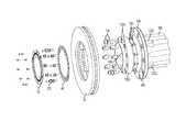
- FIG. 4is an assembly view of the brake hub assembly of FIG. 2 .
- FIG. 4 ais a detailed view of the torque members of the brake hub assembly of FIG. 2 .
- FIG. 5is a detailed view of the wheel mount flange of the brake hub assembly of FIG. 2 .
- FIG. 6is a perspective view of a second hub embodiment of the brake hub assembly.
- FIG. 7is a section view taken along lines 7 - 7 of FIG. 6 .
- FIG. 8is a section view taken along lines 8 - 8 of FIG. 6 .
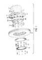
- FIG. 9is an assembly view of the brake hub assembly of FIG. 6 .
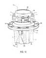
- FIG. 10is a perspective view of the brake hub assembly of FIG. 6 with the brake disk removed and notches added.
- FIG. 11is a section view taken along line 11 - 11 of FIG. 10 .
- FIG. 12is a perspective view of a torque pin of the brake hub assembly of FIG. 6 .
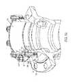
- FIG. 13is a detailed view of a brake disk installed on the brake hub assembly of FIG. 6 .
- FIG. 14is a perspective view of a spacerless torque pin installed on the brake hub assembly of FIG. 6 .
- FIG. 14 ais a perspective view of a spacerless torque pin.
- FIG. 15is a detailed view of a spacerless torque pin mounted to the wheel hub assembly of FIG. 6 with a separate spacer.
- FIG. 16 aillustrates a cylindrical coil spring
- FIG. 16 billustrates a cylindrical coil spring installed on a brake hub.
- FIG. 16 cis a section view taken along line 16 c - 16 c of FIG. 16 b.
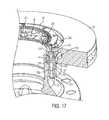
- FIG. 17-19illustrate multiple forms of installing a multi-piece torque pin on a brake hub.
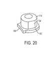
- FIG. 20illustrates a cap of a multi-piece torque pin.
- FIG. 21is a perspective view of a third hub embodiment of a brake hub assembly.
- FIG. 22is a rear perspective view of the brake hub assembly of FIG. 21 .
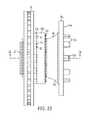
- FIG. 23is a side view of the brake hub assembly of FIG. 21 .
- FIG. 24is a section view taken along lines 24 - 24 of FIG. 23 .
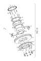
- FIG. 25is an assembly view of the brake hub assembly of FIG. 21 .
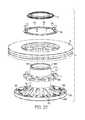
- FIG. 26is a perspective view of a fourth hub embodiment of a brake hub assembly.
- FIG. 27is a side view of the brake hub assembly of FIG. 26 .
- FIG. 28is a perspective view of the brake hub assembly of FIG. 26 with the brake disk removed.
- FIG. 29is a section view taken along lines 29 - 29 of FIG. 27 .
- FIG. 30is an assembly view of the brake hub assembly of FIG. 26 .
- FIG. 31is a front view of the raw casting used in the hub of the brake hub assembly of FIG. 26 .
- FIG. 32is a perspective view of a brake disk.
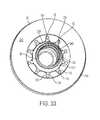
- FIG. 33is a detailed view of the brake disk of FIG. 32 installed on a brake hub.
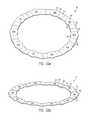
- FIG. 34illustrates the thermal expansion and contraction of the brake disk of FIG. 32 with respect to a brake hub.
- FIGS. 35 a and 35 billustrate an axial preload spring.
- FIG. 36is a perspective view of a stand off screw.
- FIG. 36 aillustrates the stand off screw of FIG. 36 installed on the brake hub assembly of FIG. 6 .
- FIG. 36 billustrates the stand off screw of FIG. 36 installed on the brake hub assembly of FIG. 2 .
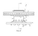
- FIG. 37is a perspective view of another brake hub assembly.
- FIG. 38is a rear perspective view of the brake hub assembly of FIG. 37 .
- FIG. 39is an assembly view of the brake hub assembly of FIG. 37 .
- FIGS. 40-42illustrate various stages of assembly of the brake hub assembly of FIG. 37 .
- FIG. 43is a section view taken along line 43 - 43 of FIG. 42 .
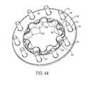
- FIGS. 44-45illustrate the wheel flange plate of the brake hub assembly of FIG. 37 .
- FIGS. 46 a , 46 b and 47illustrate a perspective view of the brake hub assembly of FIG. 37 with the stopping plate and axial preload spring in different positions.
- FIG. 48illustrates a perspective view of the brake hub assembly of FIG. 26 with added anti-rotation tabs.
- FIG. 48 ais a partial section of a perspective view of the brake hub shown in FIG. 48 .
- FIG. 49illustrates a perspective view of the brake hub assembly of FIG. 3 with added torque ridge.
- FIG. 49 ais a detailed perspective view of the brake hub assembly shown in FIG. 49 .
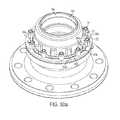
- FIG. 50 ais a perspective view of a fifth hub embodiment of the brake hub assembly.
- FIG. 50 bis a perspective view of the hub embodiment of FIG. 50 a with the torque members and spacers removed.
- FIGS. 51 and 52illustrate perspective views of an alternate mounting solution for a brake disk on a brake hub.
- FIG. 53illustrates the cap of FIG. 20 with an added protrusions.
- Exemplary embodiments of the present inventionprovide systems and methods for providing a disk brake hub assembly with improved thermodynamic isolation.
- the systems and methodsinclude torque members, spacers, and various other improvements to minimize the amount of heat transferred from the brake disk to the brake hub.
- some embodiments of the hub assemblyutilize lightweight materials, such as aluminum, to minimize rotating mass and increase efficiency.
- FIGS. 1 and 1 aillustrate a motor vehicle 10 , such as a car, truck, van, or the like having an axle tube assembly 14 that includes a drive axle 18 , a brake caliper (not shown), and a disk brake hub assembly 26 rotateably mounted on the drive axle 18 and in mechanical communication with the caliper.
- a motor vehicle 10such as a car, truck, van, or the like having an axle tube assembly 14 that includes a drive axle 18 , a brake caliper (not shown), and a disk brake hub assembly 26 rotateably mounted on the drive axle 18 and in mechanical communication with the caliper.
- one or more wheelsare typically mounted on and supported by the hub assembly 26 for rotation about an axis.
- FIGS. 1-31, 50 a and 50 billustrate various embodiments of the disk brake hub assembly 26 with improved thermodynamic isolation.
- each assembly 26includes a hub 30 a , 30 b , 30 c , 30 d , 30 e defining a central axis, a brake disk 38 coupled to the hub via a plurality of torque members 42 , an axial preload spring 46 , and a tone ring 52 .
- the wheel and hub assembly 26rotate as a single unit about the central axis.
- the useris able to control or otherwise limit the rotation of the hub assembly 26 and wheel with respect to the axle tube assembly 14 by actuating the brake caliper. More specifically, when the user actuates the caliper (e.g., by pressing the brake pedal), the caliper engages the brake disk 38 of the hub assembly 26 , creating friction that acts against the rotation of the hub. The friction also creates large amounts of heat, which in turn causes the brake disk 38 to rise in temperature, sometimes in excess of 900 degrees. Since the hub typically contains thermally sensitive elements, such as bearings, seals, and the like, it is important that the brake disk 38 be thermally isolated from the hub to limit the amount of heat that is transferred between them.
- the varying thermal loads experienced by the brake disk 38 in each braking cyclecause the disk 38 to thermally expand and contract. Since the hub is separately constructed from the disk 38 , the disk 38 experiences a much wider range of temperatures compared to the hub. Given the differences in temperature variation and thermodynamic properties, the brake disk 38 will actually expand and shrink relative to the hub.
- the present assemblyenables the brake disk 38 to “float” with respect to the hub, both axially and radially, limiting the stresses produced during the braking cycle while still allowing the braking torque to be transferred between the two elements.
- the hub 30 a , 30 b , 30 c , 30 d , 30 eincludes an axial qualifying surface to position the disk 38 with respect to the hub and the central axis.
- the disk 38is in contact with the axial qualifying surface, which in turn assures the disk 38 is substantially perpendicular the central axis.
- a first hub embodiment 30 a of the hub assembly 26is shown in FIGS. 2-5 .
- the hub 30 ais formed (e.g., cast) of austempered ductile iron for strength and durability.
- the hub 30 aincludes a substantially cylindrical body 56 a , a wheel flange 60 a extending generally radially from the body 56 a at about the axial center of the hub 30 a , and a plurality of torque members 42 , which in this embodiment are torque lugs 64 a , proximate the inboard end 68 a of hub 30 a .
- the hubalso includes a set of threaded apertures 72 a proximate the outboard end 76 a of the hub 30 a to which the drive axle 18 may be attached.
- the body 56 a of the hub 30 adefines an interior recess 80 a , extending co-axially with the central axis 34 a through the body 56 a .
- the recess 80 aincludes one or more (e.g., two) bearing seats 84 a , each sized to receive a respective bearing 86 (see FIG. 1 a ) of the bearing assembly, and may include one or more seal seats each sized to receive a respective seal, or one or more locking channels each sized to receive a locking ring.
- the body 56 aalso includes a lube channel 92 a , extending between one of the threaded apertures 72 a and the recess 80 a to monitor and maintain the fluid levels within the hub 30 a.
- the wheel flange 60 adefines a plurality wheel stud apertures 94 a , each configured to receive a wheel stud (not shown) for securing the wheel to the hub 30 a .
- the number and position of the apertures 94 agenerally correspond to the bolt pattern of the respective wheel.
- the mounting surface 98 a of the wheel flange 60 ais generally machined or finished to assure that the surface 98 a is accurately aligned with the axis 34 a of the hub 30 a , so that the wheel is properly positioned during use.
- the hub 30 aalso includes a wheel pilot surface 102 a , extending axially from the radially inward edge of the flange 60 a to assure the wheel is co-axial with the central axis 34 a .
- the hub 30 amay also include an anti-rotation ridge 103 a extending along the periphery of the wheel flange 60 a and configured to contact the flattened surface 101 a of each wheel lug 105 a to restrict rotation of wheel lugs 105 a with respect to the flange 60 a (see FIGS. 49 and 49 a ).
- the outboard edge 106 a of the wheel flange 60 amay be radiused, or curved to substantially conform to the axial deflection of the wheel's rim or disk face under a side load.
- the curve of the outboard edge 106 asubstantially matches the natural deflection of the rim to reduce residual stress within the rim and minimize the tendency of the rim to crack after exposure to repeated side loads.
- the shape of the outboard edge 106 acauses the point of contact between the hub and the wheel rim to move, albeit slightly, to help distribute the stress load over a larger area. More specifically, as the side load on the rim increases, the point of contact between the rim and the outboard edge 106 a moves radially outwardly.
- the outboard edge 106 aincludes a smooth transition from the substantially planar wheel mounting surface 98 a to a cubic (third order) curve that substantially conforms to the deflection of the wheel's disk face when under side load.
- the cubic curvethen smoothly transitions into a different, sharper curve.
- the rimis designed for a certain, maximum side load capacity. When the rim is exposed to a side load twice the maximum (e.g., such as when hitting a pot hole), the rim deflects placing the point of contact between the rim and the outboard edge 106 a at a first point (not shown) substantially corresponding with the transition between the first, shallower cubic curve and the second, sharper curve.
- the second curvemay include any combination of elliptical, parabolic, linear, circular or other curve types.
- the first curvemay also include any combination of elliptical, parabolic, linear, circular, or other curve types.
- a smooth transitionis defined as one where a graph of the slope of the curve over the transition is continuous throughout. Stated differently, the slope curve at the intersection of the mounting surface 98 a and the outboard edge 106 a does not have a discontinuity.
- the first hub embodiment 30 aalso includes a plurality (e.g., ten) of torque lugs 64 a , each formed integrally with the body 56 a and extending radially outwardly proximate the inboard end 68 a .
- Each torque lug 64 a of the first hub embodiment 30 ais substantially rectangular in shape, having a pair of flat, substantially parallel side walls 110 a and sized to fit within and move along a corresponding radial slot 254 formed by the brake disk 38 (described below).
- Each torque lug 64 aalso includes a support ledge 114 a extending along the side walls 110 a on which the second braking surface 226 of the brake disk 38 rests when installed (see FIG. 4 a ). In the illustrated embodiment, the ledges 114 a create the axial qualifying surface for the hub 30 a.
- the ledges 114 aare also sized to space the brake disk 38 a distance from the webbing 118 a extending between each pair of torque lugs 64 a while also creating a gap therebetween. Ultimately, the ledges 114 a minimize the amount of contact area between the brake disk 38 and the hub 30 a as well as produce a gap for air to circulate.
- FIGS. 6-9illustrate a second hub embodiment 30 b of the hub assembly 26 formed (e.g., cast) from an aluminum alloy to produce a low rotational mass.
- the hubemploys much of the same structure and has many of the same properties as the previously-described hub 30 a shown in FIGS. 2-5 .
- Analogous elements to those of the first embodimenthave been given the same number and a reference letter “b”.
- the following description of the hub 30 bfocuses primarily upon structure and features different than the previously-described embodiment.
- the hub 30 bincludes a plurality of wheel pilots 122 b , positioned on the outer surface of the hub body 56 b .
- the wheel pilots 122 bare generally positioned axially adjacent and outboard from the mounting surface 98 b of the wheel flange 60 b and are spaced equally along the circumference of the hub 30 b .
- the wheel pilots 122 bcenter the wheel with the axis of rotation 34 b .
- each wheel pilot 122 bincludes a machined pad 124 b extending from the hub body 56 b .
- the wheel pilots 122 bmay be formed separately and subsequently installed on the hub 30 b.
- the second hub embodiment 30 balso includes a mounting flange 126 b extending radially outwardly from the body 56 b proximate the inboard end 68 b of the hub body 56 b .
- the mounting flange 126 bdefines a plurality of apertures 130 b , each of which are sized to receive a corresponding torque pin 134 (described below).
- the mounting flange 126 bis substantially cylindrical in shape (see FIG. 9 ), however, the mounting flange 126 b may include one or more recesses or notches 138 b (see FIG. 10 ) to allow additional spacing from the brake disk 38 and promote airflow.
- the spacing pads(not shown) may be integrally formed on the mounting flange 126 b to minimize the contact area between the hub 30 b and the disk 38 .
- the second embodiment of the hub 30 balso includes a plurality of torque members 42 comprised of torque pins 134 , each press fit into an aperture 130 b of the mounting flange 126 b and secured by a fastener 142 (see FIG. 11 ).
- each torque pin 134is formed from cylindrical metal (e.g., steel, stainless steel, and the like) and includes a shank 146 sized to be received within an aperture 130 b of the mounting flange 126 b , and a head 150 engageable with the brake disk 38 (see FIG. 12 ).
- the torque pins 134are composed of a material having a thermal conductivity that is lower (e.g., between about 2% and about 25%) than that material of the hub.
- the head 150 of the torque pin 134generally includes a pair of substantially parallel side walls or flats 154 .
- the side walls 154are cut into the head 150 so the circumferential contact area between the pin 134 and the brake disk 38 is large enough to produce contact stresses below the yield point of the brake disk and pin materials. If the circumferential contact area is too small, deformation of the brake disk and pin may occur.
- each torque pin 134may also include an integral spacer 158 between the shank 146 and the head 150 to space the brake disk 38 a distance equal to the thickness of the spacer from the hub 30 b (e.g., form a gap 120 b ) and minimize the contact area between the hub 30 b and the disk 38 .
- the spacer 158also minimizes the amount of wear experienced by the softer, aluminum hub.
- no spacermay be present on the torque pin 134 ′′ (see FIGS. 14 and 14 a ).
- a spacerless torque pin 134 ′′may be used in conjunction with a separate spacer 162 (see FIG. 15 ).
- the spacer 162may be formed of one or more stacked sheets of high thermal resistance or wear resistant material such as a ceramic spacer sandwiched between two thin steel layers (not shown).
- alternate embodiments of the torque pin 134may comprise a cylindrical roll spring 166 .
- the cylindrical roll spring 166is formed from a spirally rolled piece of metal. Unlike the tubular metal body torque pin in FIG. 12 , the roll spring 166 torque pin can expand and contract to compensate for variations in aperture size, allowing for greater tolerances during the hub manufacturing process.
- the roll spring 166also has superior thermal isolation properties when compared to the torque pin of FIG. 12 .
- the roll spring 166may also includes a pair of substantially parallel side walls or flats 154 formed in the same size and manner as described above.
- the roll spring 166may also be used with, or include a spacer 162 (not shown). In alternate embodiments, the roll spring 166 may not have flats but may be configured to flex and conform to the side wall of the slots 254 to reduce the contact stresses below the yield point of the roll springs 166 and the rotor 38 .
- alternate embodiments of the torque pinmay include a multi-piece design.
- the multi-piece torque pin 134 ′includes a stud 170 ′ to be partially received within an aperture 130 b of the mounting flange 126 b , and a separately formed cap 174 ′ mated with the distal end 178 ′ of the stud 170 ′.
- the stud 170 ′ of the multi-piece torque pin 134 ′may be formed as either a cylindrical roll spring or a tubular piece and can be coupled to the mounting flange 126 b in much the same way as the previous torque pin designs (see FIGS. 18 and 19 ).
- the cap 174 ′ of the multi-piece torque pin 134 ′is substantially cylindrical in shape and is configured to substantially encompass the distal end 178 ′ of the stud 170 ′.
- the cap 174 ′includes a pair of substantially parallel side walls or flats 154 ′ (described above) to be received within and moveable along the radial slots 254 of the brake disk 38 , and an integral spacer 182 ′ to space the brake disk 38 from the mounting flange 126 b of the hub 30 b .
- the spacer 182 ′also includes a curved edge 186 ′ (see FIG. 20 ), that interacts with the hub body 30 b to limit the rotation of the cap 174 ′ on the stud 170 ′.
- the multi-piece torque pin 134 ′does not need to be properly oriented when being installed on the hub 30 b ; rather, the cap 174 ′ is free to rotate with respect to the stud 170 ′ to assure the flats 154 ′ are always properly aligned with the slots 254 of the disk 38 .
- the cap 174 ′may be formed from a low thermally conductive material, such as stainless steel, steel, or ceramic (e.g., zirconium ceramic).
- the cap 174 ′may include a set of protrusions 175 ′ (see FIG. 55 ) to at least partially restrict the rotation of the cap 174 ′ on the stud 170 ′.
- the integral spacers 158 , separate spacers 162 , and spacers 182 ′ formed in the caps 174 ′all at least partially define the axial qualifying surface (described above) for the hub 30 b when in use.
- FIGS. 21-25illustrate a third hub embodiment 30 c of the hub assembly 26 formed (e.g., cast) from an aluminum alloy similar to the second hub embodiment 30 b .
- the hubemploys much of the same structure and has many of the same properties as the previously-described hub designs 30 a , 30 b shown in FIGS. 2-5 and 6-9 .
- Analogous elementshave been given the same number and reference letter “c”. The following description of the hub 30 c focuses primarily upon structure and features different than the previously-described embodiments.
- the third hub embodiment 30 cincludes a wheel flange 60 c that extends radially and axially outwardly from the outboard end 76 c of the hub 30 c .
- the mounting surface 98 c of the wheel flange 60 cis positioned axially outboard of the hub body 56 c and defines a plurality of wheel stud apertures 94 c , each configured to receive a corresponding wheel stud (not shown).
- a plurality of reinforcing ribs 190 care formed into the flange itself.
- the ribs 190 cextend generally radially along the outboard side of the flange 60 c.
- the third hub embodiment 30 calso includes a plurality of (e.g., five) wheel pilots 122 c , each extending axially outwardly from the mounting surface 98 c of the wheel flange 60 c . As described above, the wheel pilots 122 c are positioned to align the wheel with the central axis 34 c of the hub 30 c .
- the inboard end 68 c of the third hub embodiment 30 cincludes a ridge 194 c , formed into the body 56 c and configured to act as a mounting guide for a press-on style tone ring 52 ′′.
- FIGS. 26-31illustrate a fourth hub embodiment 30 d of the hub assembly 26 formed (e.g., cast) from austempered ductile iron similar to the first hub embodiment 30 a .
- the hubemploys much of the same structure and has many of the same properties as the previously-described hub designs 30 a , 30 b , 30 c shown in FIGS. 2-5, 6-9 , and 21 - 25 .
- Analogous elementshave been given the same number and the reference letter “d”. The following description of the hub 30 d focuses primarily upon structure and features different than the previously-described embodiment.
- each rib 198 dis generally spaced evenly along the circumference of the flange 60 d and includes a wheel stud boss 96 d formed therein.
- the wheel flange 60 dalso includes a perimeter rib 202 d , an annular rib 206 d extending around the flange and radially inward from the perimeter rib 202 d , and one or more secondary ribs 210 d extending radially and generally perpendicular to ribs 202 d , 206 d .
- the perimeter rib 202 dextends along the outer diameter of the wheel flange 60 d at a height greater than the height of the wheel stud bosses 96 d .
- the annular rib 206 dis concentric with the perimeter rib 202 d , generally extending between the various wheel stud bosses 96 d at a height lower than the bosses themselves.
- each rib 202 d , 206 d , and 210 dmay vary.
- the hub 30 dmay include one or more anti-rotation tabs 205 d to restrict rotation of the wheel lugs 105 d positioned within the bosses 96 d (see FIGS. 48 and 48 a ).
- the fourth hub embodiment 30 dalso includes a plurality of (e.g., five) wheel pilots 122 d , each extending axially outwardly from the mounting surface 98 d of the wheel flange 60 d .
- the wheel pilots 122 dare positioned to align the wheel with the central axis 34 d of the hub 30 d .
- the wheel pilots 122 dare also each staggered with respect to the reinforcing ribs 198 d , or located between ribs 198 d , to limit casting porosity.
- each wheel pilot 122 dis positioned such that an axis, oriented parallel to the central axis 34 d , will not pass through both the wheel pilot and the reinforcing ribs at the same time.
- the wheel pilots 122 dare staggered from the ribs 198 d , the variation in overall thickness of the cast material is minimized, thereby substantially reducing porosity.
- the hub assembly 26also includes a brake disk 38 .
- the brake disk 38includes a first plate 214 having a first brake surface 218 , and a second plate 222 spaced axially from the first plate 214 and having a second brake surface 226 .
- the brake disk 38also includes a plurality of ribs or vanes 230 extending radially between the first and second plates 214 , 222 to define a plurality of cooling channels 234 therebetween.
- the second plate 222 of the brake disk 38extends radially inwardly of the inner diameter of the first plate 214 to define a pilot diameter 238 .
- the pilot diameter 238includes a plurality of pilot surfaces 242 , each configured to engage the pilot cylinder 246 of the hub and position the brake disk 38 co-axially with the hub along the central axis.
- each pilot surface 242includes a pair of chamfers 250 , to minimize the contact area between the hub and the disk 38 to reduce heat transfer. In the illustrated embodiment, less than about 20% of the circumference of the pilot diameter 238 is in contact with the hub.
- the size of the chamfers 250can be modified (e.g., changing the size of the pilot surfaces 242 ) so that less than 15% of the circumference of the pilot diameter is in contact with the hub.
- the second plate 222 of the brake disk 38also defines a plurality of radial slots 254 .
- Each slot 254is open to the pilot diameter 238 and extends radially outwardly, separating two pilot surfaces 242 .
- each slot 254is sized to receive a torque member 42 therein (see FIG. 33 ). More specifically, each slot 254 is sized to receive the head 150 of a torque pin 134 (e.g., in the second hub embodiment 30 b and third hub embodiment 30 c , see FIG. 8 ) or a torque lug 64 a , 64 d (e.g., in the first hub embodiment 30 a and fourth hub embodiment 30 d , see FIG. 3 ).
- a torque pin 134e.g., in the second hub embodiment 30 b and third hub embodiment 30 c , see FIG. 8
- a torque lug 64 a , 64 de.g., in the first hub embodiment 30 a and fourth hub embodiment 30 d , see FIG. 3
- each channel 234At least 50% of the area of the radially interior opening 236 (see FIG. 32 ) of each channel 234 is positioned above the torque members 42 of the hub so as to minimize any resistance to the airflow. In other embodiments, at least 90% of each interior opening 236 is positioned above the torque members 42 . In still other embodiments, the torque member 42 does not extend axially beyond the inboard edge of the interior opening 236 of each channel 234 . Stated differently, the torque members 42 do not extend axially beyond the second plate 222 of the brake disk 38 by more than 50% of the distance D between the first plate 214 and the second plate 222 (see FIG. 32 ). Alternatively, the torque members 42 do not extend beyond 10% of the distance D.
- the brake disk 38When installed on the hub, the brake disk 38 is allowed to “float” with respect to the hub to compensate for differences in thermal expansion between the two. More specifically, the torque members 42 move within the slots 254 of the brake disk 38 as the disk expands and contracts (see FIG. 34 ) but maintain contact with the respective axial qualifying surface. This allows the torque members 42 to transfer braking torque from the brake disk 38 to the hub without restraining the brake disk 38 from thermally induced movement and while maintaining the correct orientation with respect to the central axis.
- the hub assembly 26also includes an axial preload spring 46 coupleable to the hub to secure the brake disk 38 thereto.
- the axial preload spring 46is substantially annular in shape and is formed from stamped spring steel.
- the spring 46generally includes a plurality of circumferentially spaced base portions 258 , each defining an aperture 262 , and a plurality of substantially V-shaped spring portions 266 each extending between adjacent base portions 258 .
- each base portion 258 of the spring 46is coupled to a respective torque member 42 of the hub by a stand off screw 270 .
- the spring portions 266contact the brake disk 38 and axially bias the disk 38 towards the axial qualifying surface.
- the preload spring 46works in tandem with the axial qualifying surface (e.g., at least one of the spacers 162 , the support ledges 114 a , 114 d , the mounting flange 126 b , 126 c , and the like) to allow the disk 38 to move axially or “float” with respect to the hub.
- the axial preload spring 46applies an axial biasing force sufficient to ensure that the disk 38 is in constant contact with the axial qualifying surface while compensating for axial expansion and contraction of the disk 38 due to temperature changes.
- the axial preload spring 46is shown as a single, annular unit, the spring 46 may be separated into one or more separate spring members (not shown).
- the axial preload spring 46may include a pair of “C” shaped portions.
- each axial preload spring 46may include an annular portion extending about 180 degrees.
- the hub assembly 26also includes a plurality of stand off screws or connectors 270 , each having a mounting portion 274 , a body 278 , and an extension portion 282 opposite the mounting portion 274 .
- the stand-off screws 270secure the axial preload spring 46 to the hub while also providing a thermally isolated mounting for the tone ring 52 so that it is spaced a distance from the hub.
- each stand off screw 270When the hub is assembled, the mounting portion 274 of each stand off screw 270 is coupled (e.g., threadably engaged) to a corresponding torque member 42 of the hub, securing the spring 46 to the torque members 42 , and the extension portion 282 extends axially outwardly from the hub to produce a threaded aperture 286 .
- the extension portion 282is configured to provide minimal resistance to the airflow through the channels 234 of the brake disk 38 .
- the hub assembly 26also includes a tone ring 52 .
- the tone ring 52is substantially annular in shape, and includes a plurality of recesses spaced evenly about the circumference of the ring.
- the tone ring 52interacts with a sensor (not shown) to allow the user to monitor the rotation of the hub assembly 26 with respect to the axle tube assembly 14 .
- the tone ring 52may include a plurality of cuts or protrusions in place of the recesses, dependent upon the style of sensor being used.
- the tone ring 52is coupled to the extension portion 282 of the standoff screw 270 , however in the third and fourth hub embodiments 30 c , 30 d , a press-on tone ring 52 ′′ is coupled directly to the hub body 56 b , 56 d.
- the brake hub assembly 26is typically pre-assembled as a unit before being installed on the axle tube assembly 14 of a motor vehicle 10 .
- the useraxially introduces the brake disk 38 onto the inboard end of the hub, making sure to align each torque member 42 with a corresponding slot 254 and the pilot surfaces 242 with the pilot cylinder of the hub.
- a torque lug 64 a , 64 de.g., in the first and fourth embodiments, see FIG. 3
- the head 150 of a torque pin 134e.g., in the second and third embodiments, see FIG. 8
- each radial slot 254is positioned within each radial slot 254 .
- the axial preload spring 46is then positioned on the hub making sure to align each base portion 258 with a corresponding torque member 42 and each spring portion 266 with the brake disk 38 .
- the spring 46is then coupled to the hub by a plurality of stand off screws 270 , each of which pass through a corresponding aperture 262 of the spring 46 .
- the tone ring 52is then attached to the assembly 26 by coupling it to the extended portions 282 of the stand off screws 270 .
- the axial preload spring 46may be coupled directly to the hub with fasteners and the tone ring 52 ′′ may be pressed onto a corresponding ridge 194 d (see FIG. 29 ). Once the assembly is complete, it may be installed onto the axle tube assembly 14 of a motor vehicle 10 with the proper bearings and seals using the standard installation processes well known in the art.
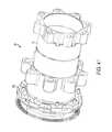
- FIGS. 37-45Another hub assembly 26 ′ is illustrated in FIGS. 37-45 .
- This hub assembly 26 ′employs much of the same structure and has many of the same properties as the previously-described hub assembly 26 shown in FIGS. 1-31 . Analogous elements have been given the same reference number and the prime symbol. The following description of the hub assembly 26 ′ focuses primarily upon structure and features different than the previously-described embodiment.
- the hub assembly 26 ′is configured to be installed on the axle of a motor vehicle and act as a mounting location for one or more of the vehicle's wheels (not shown).
- the brake hub 30 ′is designed to allow the user to remove and install the brake disk 38 ′, such as for maintenance or replacement, without having to remove the hub 30 ′ from the axle, leaving the bearing assembly and seals undisturbed.
- the hub assembly 26 ′includes a hub 30 ′, a wheel flange plate 290 ′, a brake disk 38 ′, and an axial preload spring 46 ′.
- the hub 30 ′ of the hub assembly 26 ′includes a substantially cylindrical body 56 ′, a plurality of torque lugs 64 ′ positioned proximate the inboard end 68 ′ of the hub body 56 ′, a plurality of wheel lugs 294 ′ positioned near the axial center of the hub body 56 ′, and a plurality of threaded lugs 296 ′ proximate the outboard end 76 ′ of the hub body 56 ′.
- the body 56 ′ of the hub 30 ′also defines an interior recess 80 ′ that includes seats for the bearings of the bearing assembly and any necessary seals.
- the torque lugs 64 ′extend radially outwardly from the body 56 ′ proximate the inboard end 68 ′.
- the lugs 64 ′are formed integrally with the body 56 ′ and are spaced equidistantly along its circumference. Similar to the torque lugs of the first and fourth hub embodiments 30 a , 30 d , each lug 64 ′ of the hub 30 ′ has a pair of substantially parallel side walls 110 ′ configured to be received within and moveable along the slots 254 ′ of the brake disk 38 ′.
- the wheel lugs 294 ′extend radially outwardly from the body 56 ′ near the axial center of the hub body. As with the torque lugs 64 ′, the wheel lugs 294 ′ are formed integrally with the hub body 56 ′ and are spaced equidistantly along its circumference. Each wheel lug 294 ′ includes an axially extending threaded aperture 298 ′, configured to threadably receive a bolt 302 ′. In the illustrated embodiment, each wheel lug 294 ′ is sized and spaced so that the brake disk 38 ′ can slide past the lugs 294 ′ without interference. More specifically, each wheel lug 294 ′ is sufficiently small to pass through a corresponding radial slot 254 ′ of the brake disk.
- the wheel flange plate 290 ′is substantially annular in shape and defines a plurality of wheel stud apertures 94 ′.
- the wheel flange plate 290 ′also includes a wall 297 ′ extending perpendicular to the mounting surface 98 ′ and along the inner circumference of the plate 290 ′.
- Wall 297 ′varies in radial distance from the central axis 34 ′ and defines a plurality of hub pilots 300 ′ at a first radial distance from the central axis 34 ′ and a plurality of wheel pilots 304 ′ at a second, greater radial distance from the central axis 34 ′ (see FIG. 44 ).
- the hub pilots 300 ′are configured to engage the pilot cylinder 246 ′ of the hub 30 ′ and co-axially align the plate 290 ′ with the central axis 34 ′ and the wheel pilots 304 ′ are configured to maintain the concentricity between the plate 290 ′ and the wheel.
- the wall 297 ′also provides rigidity to the plate 290 ′.
- the plate 290 ′also defines a plurality of notches 306 ′, each positioned between a pair of hub pilots 300 ′ and sized slightly larger than a threaded lug 296 ′ of the hub 30 ′.
- the plate 290 ′also defines a plurality of mounting apertures 308 ′, each positioned between a pair of notches 306 ′ and sized to receive a high strength bolt 302 ′ with a reduced head diameter.
- the apertures 308 ′are recessed axially from the mounting surface 98 ′ and sized to accommodate the reduced diameter heads so the bolts 302 ′ will not interfere with the wheel when it is installed on the hub 30 ′. More specifically, the apertures 308 ′ are sized to accept the reduced diameter heads but are too small to receive typical sized bolt heads. Therefore, the bolt head acts as a safety check since lower quality fasteners with standard size heads cannot be used.
- the wheel flange plate 290 ′can be formed from austempered ductile iron. As such, the material of the plate 290 ′ is similar in hardness to the material of typical wheel studs 312 ′. The similar hardness of the plate 290 ′ and stud 312 ′ prevent the studs 312 ′ from being pressed into the plate 290 ′. To restrict the studs 312 ′ from rotating once installed, a notch 314 ′ is formed in the stud 312 ′.
- the notch 314 ′contacts a flange or raised surface 318 ′, formed in the plate 290 ′, thereby restricting the stud 312 ′ from rotating with respect to the plate 290 ′ (see FIG. 45 ).
- the brake hub assembly 26 ′also includes a pair of stopping plates 310 ′.
- Each plate 310 ′is substantially semi-annular in shape and is configured to be bolted to the outboard side of the torque lugs 64 ′ to establish an outboard travel stop and axial qualifying surface for disk 38 ′ on the hub 30 ′.
- the stopping plates 310 ′work in tandem with the axial preload spring 46 , which acts as an inboard travel stop for disk 38 ′ and applies a constant outboard force to bias the disk 38 against the stopping plates 310 ′.
- each stopping plate 310 ′extends roughly half the circumference of the hub 30 ′ so the stopping plates 310 ′ can be installed without needing to slide them along the length of the hub 30 ′.
- an annular piecemay be used.
- the brake hub 26 ′may include a stopping plate 310 ′ attached on the inboard side with one or more axial preload springs 46 on the outboard side (see FIGS. 46 a , 46 b and 47 ).
- the usercouples the axial preload spring 46 ′ to the inboard side of the torque lugs 64 ′ with a set of stand off screws and couples the tone ring 52 ′ to the extension portion of the stand off screws (not shown).
- the usermay couple the axial preload spring 46 ′ directly to the lugs 64 ′ using a standard fastener while coupling the tone ring 52 ′ to the hub 30 ′ using a set of independent standoff spacers 322 ′ (see FIGS. 40 and 43 ).
- the usercan then install the hub 30 ′ onto the axle of the motor vehicle with the proper bearings and seals as is well known in the art.
- the userintroduces the brake disk 38 ′ axially over the outboard end 76 ′ of the hub 30 ′, sliding the disk 38 in an inboard direction along the hub 30 ′, passing the threaded lugs 296 ′ and the wheel lugs 294 ′ until the disk 38 ′ contacts the axial preload spring 46 ′.
- the usercouples (e.g., bolts) the stopping plates 310 ′ to the outboard side of the torque lugs 64 ′, securing the brake disk 38 ′ to the hub 30 ′ between the preload spring 46 ′ and the plates 310 ′ (see FIG. 41 ).
- the wheel flange plate 290 ′is coupled (e.g., bolted) to the wheel lugs 294 ′ with bolts 302 ′ (see FIG. 42 ).
- the usercan remove the brake disk 38 ′ from the hub 30 ′ without removing the hub 30 ′ from the axle.
- the userremoves the bolts 302 ′ securing the wheel flange plate 290 ′ to the hub 30 ′.
- the userthen removes the wheel flange plate 290 ′ from the hub 30 ′ by sliding the plate 290 ′ in an outboard direction, making sure to align the notches 306 ′ with the threaded lugs 296 ′.
- the axial preload spring 46 ′, stand off screws 270 ′ and tone ring 52 ′may remain attached to the hub 30 ′ during both assembly and disassembly.
- FIGS. 50 a and 50 billustrate a fifth hub embodiment 30 e of the hub assembly 26 formed (e.g., cast) from an aluminum alloy to produce a low rotational mass.
- the hubemploys much of the same structure and has many of the same properties as the previously-described hub 30 b shown in FIGS. 6-19 .
- Analogous elements to those of the previous embodimenthave been given the same number and a reference letter “e”. The following description of the hub 30 e focuses primarily upon structure and features different than the previously-described embodiment.
- the fifth hub embodiment 30 eincludes a mounting flange 126 e extending radially outwardly from the body 56 e proximate the inboard end 68 e of the hub body 56 e .
- the mounting flange 126 edefines a first set 350 e and a second set 354 e of apertures.
- the first set of apertures 350 eare sized to receive a spacer 358 e therein while the second set 354 e is sized to receive a corresponding torque pin 134 (described above).
- the spacers 358 eBy separating the mounting locations of the spacers 358 e and the torque pins 134 , the high heat areas (i.e., the spacers) are separated from the high torque areas (i.e., the torque pins 134 ), increasing the strength of the overall assembly. Furthermore, by making the spacers 358 e a separate element, they do not need to be able to withstand the large loads present during braking and can be formed from more thermally insulating material, such as stainless steel, ceramic, and the like.
- the fifth hub embodiment 30 ealso includes a groove 362 e extending along the mounting flange 126 e .
- the groove 362 eis configured to at least partially receive the protrusions 175 ′ of the cap 174 ′ positioned on the torque pins 134 (see FIG. 55 ).
- the groove 362at least partially restricts the rotation of the cap 174 ′ with respect to the pin 134 .
- the userinserts the spacers 358 e into the corresponding apertures 350 e of the mounting flange 126 e .
- the userthen machines the axial surfaces 359 e of the spacers 358 e while the spacers 358 e are installed in the hub 30 e .
- the usermay insert the torque pins 134 into their corresponding apertures 354 e.
- the usermay first machine the inboard surface 360 e of the mounting flange 126 e to assure it is perpendicular to the central axis. The user then presses each spacer 358 e into a corresponding aperture 350 e , relying on minimal part-to-part variation in the spacers 350 e to maximize accuracy.
Landscapes
- Engineering & Computer Science (AREA)
- Mechanical Engineering (AREA)
- General Engineering & Computer Science (AREA)
- Transportation (AREA)
- Braking Arrangements (AREA)
Abstract
Description
Claims (16)
Priority Applications (1)
| Application Number | Priority Date | Filing Date | Title |
|---|---|---|---|
| US13/436,422US9566957B2 (en) | 2011-03-31 | 2012-03-30 | Disk brake hub assembly |
Applications Claiming Priority (2)
| Application Number | Priority Date | Filing Date | Title |
|---|---|---|---|
| US13/077,883US9897154B2 (en) | 2011-03-31 | 2011-03-31 | Disk brake hub assembly |
| US13/436,422US9566957B2 (en) | 2011-03-31 | 2012-03-30 | Disk brake hub assembly |
Related Parent Applications (1)
| Application Number | Title | Priority Date | Filing Date |
|---|---|---|---|
| US13/077,883Continuation-In-PartUS9897154B2 (en) | 2011-03-31 | 2011-03-31 | Disk brake hub assembly |
Publications (2)
| Publication Number | Publication Date |
|---|---|
| US20120247882A1 US20120247882A1 (en) | 2012-10-04 |
| US9566957B2true US9566957B2 (en) | 2017-02-14 |
Family
ID=46925780
Family Applications (1)
| Application Number | Title | Priority Date | Filing Date |
|---|---|---|---|
| US13/436,422Active2031-06-09US9566957B2 (en) | 2011-03-31 | 2012-03-30 | Disk brake hub assembly |
Country Status (1)
| Country | Link |
|---|---|
| US (1) | US9566957B2 (en) |
Cited By (3)
| Publication number | Priority date | Publication date | Assignee | Title |
|---|---|---|---|---|
| USD823212S1 (en)* | 2017-01-25 | 2018-07-17 | Arconic Inc. | Spindle hub for wheel |
| US10882354B2 (en) | 2017-05-25 | 2021-01-05 | Hendrickson Usa, L.L.C. | Wheel hub for heavy-duty vehicles |
| US11428283B2 (en)* | 2017-08-31 | 2022-08-30 | Freni Brembo S.P.A. | Brake disc assembly |
Families Citing this family (3)
| Publication number | Priority date | Publication date | Assignee | Title |
|---|---|---|---|---|
| ITBS20130183A1 (en)* | 2013-12-18 | 2015-06-19 | Freni Brembo Spa | CONNECTION SYSTEM BETWEEN THE BRAKING RANGE AND THE UNDISCO BELL FOR DISC BRAKE |
| DE102018128793A1 (en)* | 2018-11-16 | 2020-05-20 | Faiveley Transport Witten Gmbh | Centering ring for a shaft brake disc of a rail vehicle and shaft brake disc for a rail vehicle with a centering ring |
| CN112319132B (en)* | 2020-11-25 | 2022-05-24 | 浙江博鑫涵汽车零部件有限公司 | Novel automobile wheel hub subassembly |
Citations (110)
| Publication number | Priority date | Publication date | Assignee | Title |
|---|---|---|---|---|
| US1473140A (en) | 1919-09-25 | 1923-11-06 | Packard Motor Car Co | Motor vehicle |
| US2753959A (en)* | 1951-04-12 | 1956-07-10 | American Steel Foundries | Brake rotor |
| US3530960A (en)* | 1968-03-15 | 1970-09-29 | Bergische Stahlindustrie | Wheel and brake construction |
| US3624749A (en) | 1970-10-16 | 1971-11-30 | American Velcro Inc | Hair curlers |
| US3772548A (en)* | 1972-06-20 | 1973-11-13 | Rockwell International Corp | Wheel speed sensor |
| US3994370A (en) | 1975-04-15 | 1976-11-30 | Knorr-Bremse Gmbh | Brake disc |
| US4026393A (en) | 1975-03-12 | 1977-05-31 | Knorr-Bremse Gmbh | Brake disc for disc brakes on rail vehicles |
| US4042071A (en) | 1975-04-03 | 1977-08-16 | Knorr-Bremse Gmbh | Wheel and axle assembly for railway vehicles having disc brakes |
| US4108286A (en) | 1976-09-03 | 1978-08-22 | Knorr-Bremse Gmbh | Brake disc for an axle of a railway vehicle |
| US4110647A (en) | 1977-01-13 | 1978-08-29 | The Bendix Corporation | Wheel speed sensor |
| US4152099A (en) | 1977-05-31 | 1979-05-01 | Milton Roy Company | Magnetically coupled pump and impeller assembly therefor |
| US4281745A (en) | 1978-06-27 | 1981-08-04 | Knorr-Bremse Gmbh | Brake disk for disk brakes on a rail vehicle |
| EP0127932A1 (en) | 1983-04-07 | 1984-12-12 | Eaton Corporation | Brake disc mounting |
| JPS62209234A (en)* | 1986-03-05 | 1987-09-14 | Fuji Seisakusho:Kk | Disc brake |
| US4792020A (en) | 1986-12-19 | 1988-12-20 | Honda Giken Kogyo Kabushiki Kaisha | Vehicle wheel assembly |
| US4811992A (en) | 1986-12-17 | 1989-03-14 | Bergische Achsenfabrik Fr. Kotz & Sohne | Wheel-mounting arrangement with emergency bearing surface |
| US4840348A (en) | 1985-06-06 | 1989-06-20 | Usui Kokusai Sangyo Kabushiki Kaisha | Valve actuator for slide exhaust brake systems |
| US4880281A (en) | 1983-12-08 | 1989-11-14 | Skf Industrial Trading & Development Co. B.V. | Wheel bearing |
| US4913266A (en) | 1987-09-23 | 1990-04-03 | Lucas Industries Public Limited Company | Disc brakes |
| US5007508A (en)* | 1986-02-05 | 1991-04-16 | Societe Europeenne De Propulsion | Friction system using refractory composite materials |
| US5190124A (en) | 1990-03-26 | 1993-03-02 | Nissin Kogyo Kabushiki Kaisha | Brake discs |
| US5261511A (en) | 1991-12-17 | 1993-11-16 | Allied-Signal Inc. | Lightweight and high thermal conductivity brake rotor |
| US5273140A (en) | 1992-09-25 | 1993-12-28 | Allied-Signal Inc. | Brake disc annular drive insert |
| EP0418532B1 (en) | 1989-09-12 | 1994-04-13 | IVECO FIAT S.p.A. | Assembly for connecting a wheel to a vehicle axle |
| US5344219A (en) | 1991-10-24 | 1994-09-06 | Csir | Motor vehicle wheel frame |
| US5352305A (en) | 1991-10-16 | 1994-10-04 | Dayton Walther Corporation | Prestressed brake drum or rotor |
| US5435420A (en)* | 1994-08-16 | 1995-07-25 | Eaton Corporation | Thermal insulating wheel spacer |
| US5439077A (en) | 1993-03-19 | 1995-08-08 | Knorr-Bremse Ag | Brake disk for wheel disk brakes |
| US5507367A (en) | 1992-01-24 | 1996-04-16 | Ab Volvo | Wheel hub and brake disc arrangement for heavy trucks |
| US5540303A (en) | 1992-06-02 | 1996-07-30 | Ab Volvo | Wheel hub and brake disc arrangement for heavy vehicles |
| US5568846A (en)* | 1992-01-24 | 1996-10-29 | Ab Volvo | Wheel hub and brake disk arrangement for heavy trucks |
| US5739684A (en) | 1996-08-19 | 1998-04-14 | Webb Wheel Products, Inc. | Unitarily formed hub and ABS exciter ring |
| EP0872659A1 (en) | 1997-04-19 | 1998-10-21 | Dr.Ing.h.c. F. Porsche Aktiengesellschaft | Brake disc, in particular internally ventilated brake disc |
| US5851056A (en) | 1996-06-03 | 1998-12-22 | The B. F. Goodrich Company | Aircraft brake heat shield having easily removed heat shield sections |
| US5988324A (en) | 1996-01-11 | 1999-11-23 | Skf Industries S. P. A. | Wheel hub bearing unit |
| US5988613A (en) | 1996-06-17 | 1999-11-23 | Volvo Lastvagnar Ab | Wheel hub and brake disc arrangement for a vehicle wheel |
| US6098764A (en) | 1997-03-05 | 2000-08-08 | Knorr-Bremse Systeme fur Scheinfahrzeuge GmbH | Shaft brake disk for rail vehicle disk brake systems and method of making same |
| US6116386A (en) | 1997-06-27 | 2000-09-12 | Dr. Ing. H.C.F. Porsche Ag | Divided brake disk for thermal compensation |
| US6139215A (en) | 1995-11-30 | 2000-10-31 | Knorr-Bremse System Fuer Nutzfahrzeuge Gmbh | Disc-hub connection, in particular for utility vehicle disc brakes |
| US6145632A (en) | 1997-02-21 | 2000-11-14 | S.K.F. Industrie S.P.A. | Wheel hub bearing unit and brake connection |
| US6161661A (en) | 1997-10-24 | 2000-12-19 | Knorr-Bremse Systeme Fur Nutzfahrzeuge Gmbh | Brake disc for a disc braking system |
| US6224266B1 (en) | 1998-09-18 | 2001-05-01 | Ntn Corporation | Wheel bearing device |
| US6247547B1 (en) | 1998-04-21 | 2001-06-19 | A.S.V., Inc. | Suspension and drive mechanism for a multi-surface vehicle |
| US6257678B1 (en) | 1999-09-23 | 2001-07-10 | Meritor Heavy Vehicle Systems, Llc | Vehicle hub having reduced lubricant cavity |
| US6305510B1 (en) | 1996-12-12 | 2001-10-23 | Delphi Technologies, Inc. | Disc brake system |
| US6330937B1 (en) | 1998-07-28 | 2001-12-18 | Volvo Lastvagnar Ab | Wheel hub and brake disc arrangement for heavy vehicles |
| US6364426B1 (en) | 1998-08-05 | 2002-04-02 | Kelsey-Hayes Company | Vehicle wheel hub and bearing unit assembly and method for producing same |
| US6374956B1 (en) | 1998-12-23 | 2002-04-23 | Daimlerchrysler Ag | Brake assembly with a nonmetal friction ring and method of making same |
| WO2002033280A1 (en) | 2000-10-17 | 2002-04-25 | Freni Brembo S.P.A. | A disk-brake disk |
| US6457567B1 (en) | 1998-08-15 | 2002-10-01 | Delphi Technologies, Inc. | Leaf spring for a disc brake |
| US6464045B2 (en) | 2001-03-15 | 2002-10-15 | Delphi Technologies, Inc. | Rotor retaining clip |
| US6467588B1 (en) | 1998-09-02 | 2002-10-22 | Knorr-Bremse Systeme Fuer Nutzfahrzeuge Gmbh | Wheel and/or brake disk hub and brake disk |
| US20020157908A1 (en)* | 2000-03-24 | 2002-10-31 | Burgoon Donald L. | Brake hub with floating rotor and mounting flange allowing simplified rotor removal and replacement |
| DE10128072A1 (en) | 2001-06-09 | 2002-12-12 | Daimler Chrysler Ag | Wheel hub with brake disc has wheel flange mounted on outer contour of brake disc pot thereby separating drive function from brake function |
| US6543858B1 (en) | 2001-10-02 | 2003-04-08 | Meritor Heavy Vehicle Technology, Llc | Wheel end assembly |
| US6564912B1 (en) | 1999-06-28 | 2003-05-20 | Otto Sauer Achsenfabrik of Keilberg | Brake disk |
| US6564913B2 (en) | 2000-09-21 | 2003-05-20 | Knorr-Bremse Systeme Fuer Nutzfahrzeuge Gmbh | Brake disk/hub assembly for vehicle disk brakes |
| US6604794B1 (en) | 2002-02-04 | 2003-08-12 | Meritor Heavy Vehicle Technology, Llc | Uni-pilot hub/drum system |
| US6612657B1 (en) | 2000-11-01 | 2003-09-02 | Gunite Corporation | Outboard ribbed wheel hub |
| US6626273B1 (en) | 1998-09-02 | 2003-09-30 | Knorr-Bremse Systeme Fuer Nutzfahrzeuge Gmbh | Brake disk and corresponding axle hub |
| US6702398B2 (en) | 1999-06-09 | 2004-03-09 | The Timken Company | Hub assembly having minimum runout and process for producing the same |
| US6742233B2 (en) | 1999-11-12 | 2004-06-01 | Knorr-Bremse Systeme für Schienenfahrzeuge GmbH | Method of making a friction ring for a brake disk |
| US20040182660A1 (en) | 2001-06-13 | 2004-09-23 | Lorenzo Cavagna | Composite disk for a disk brake |
| US20040195059A1 (en)* | 2001-11-26 | 2004-10-07 | Mark Williams Enterprises, Inc. | Disc brake rotor mounting system |
| US6829825B1 (en) | 2003-01-31 | 2004-12-14 | Robert Bosch Corporation | Process of manufacturing a corner assembly |
| US6880682B2 (en) | 2001-11-27 | 2005-04-19 | Freni Brembo S.P.A. | Wheel support for vehicles with disk brakes |
| DE10351592B3 (en) | 2003-11-05 | 2005-04-28 | Knorr Bremse Systeme | Brake disc especially for rail vehicles has friction ring centered and locked against rotation through slide elements each mounted in insert bore in hub or wheel disc |
| US6910556B1 (en) | 1999-04-21 | 2005-06-28 | Knorr-Bremse Systeme Fuer Nutzfahrzeuge Gmbh | Brake disk-hub combination and intermediate elements for a brake disk-/hub combination |
| US20050206148A1 (en) | 2004-03-04 | 2005-09-22 | Bendix Commercial Vehicle Systems Llc | Sensor arrangement for use with an air disc brake |
| US6962242B2 (en) | 2002-07-18 | 2005-11-08 | Meritor Heavy Vehicle Systems Cameria Spa | Brake rotor |
| USRE38874E1 (en) | 1995-04-27 | 2005-11-15 | Knorr-Bremse Systeme Fuer Nutzfahrzeug Gmbh | Disc brake for vehicles having insertable actuator |
| US7098764B2 (en) | 2004-03-18 | 2006-08-29 | Nexans | Main conductor for a capacitively controlled high-voltage winding |
| US7104368B2 (en) | 2002-01-14 | 2006-09-12 | Freni Brembo S.P.A | Disk-brake disk |
| US7111911B2 (en) | 2001-04-30 | 2006-09-26 | Knorr-Bremse Systeme Fuer Nutzfahrzeuge Gmbh | Wheel hub |
| US7159698B2 (en) | 2004-07-22 | 2007-01-09 | Bendix Spicer Foundation Brake, Llc | Disc brake rotor assembly with replaceable wear surfaces |
| US7159316B2 (en) | 2004-10-28 | 2007-01-09 | Robert Bosch Gmbh | Method of manufacturing a modular corner assembly |
| US7163091B2 (en) | 2003-05-16 | 2007-01-16 | Bendix Commercial Vehicle Systems Llc | Rotor with locking pins |
| US20070062766A1 (en) | 2003-12-09 | 2007-03-22 | Knorr-Bremse Systeme Fuer Nutzfahrzeuge Gmbh | Pneumatically actuated disk brake with electromotive adjusting devices and method for controlling the disk brake |
| DE10257719B4 (en) | 2002-12-11 | 2007-04-12 | Herbert Alber | Composite brake disc |
| US7228946B2 (en) | 2001-10-02 | 2007-06-12 | Knorr-Bremse Systeme Fuer Nutzfahrzeuge Gmbh | Brake disc for a disc brake |
| US20070175715A1 (en)* | 2004-07-16 | 2007-08-02 | Knorr-Bremse System Fuer Nutzfahrzeuge Gmbh | Pole wheel which can be connected to a wheel hub of a motor vehicle |
| US7255205B2 (en) | 2004-03-18 | 2007-08-14 | Bendix Spicer Foundation Brake Llc | Disc brake located outside wheel envelope |
| US20070193837A1 (en) | 2006-02-21 | 2007-08-23 | Lamb Roger A | Two-piece floating disc brake assembly |
| US7261192B2 (en) | 2000-11-13 | 2007-08-28 | Knorr-Bremse Systeme Fuer Nutzfahrzeuge Gmbh | Brake disk and method for the production thereof |
| US7281769B2 (en) | 2004-07-19 | 2007-10-16 | Gunite Corporation | Two-component wheel hub |
| US20070246269A1 (en) | 2004-10-08 | 2007-10-25 | Knorr-Bremse Systeme Fuer | Method for the creation of a pole wheel/wheel hub connection and arrangement thereof |
| US20070286961A1 (en) | 2004-10-29 | 2007-12-13 | Knorr-Bremse Systeme Fuer Nutzfahrzeuge Gmbh | Wear-resistant brake disc or brake drum and method for producing same |
| US20080060890A1 (en) | 2006-08-24 | 2008-03-13 | Bendix Spicer Foundation Brake Llc | Flexibly mounted disc brake rotor for pneumatic, electromotive, and/or hydraulic disc brakes |
| US7374024B2 (en) | 2004-05-11 | 2008-05-20 | Knorr-Bremse Systeme Fuer Nutzfahrzeuge Gmbh | Brake disc/hub assembly with displaceable brake discs |
| US20080128229A1 (en) | 2005-05-17 | 2008-06-05 | Knorr-Bremse Systeme Fuer Nutzfahrzeuge Gmbh | System for Connecting a Brake Disc and Hub |
| US20080135359A1 (en) | 2006-12-11 | 2008-06-12 | Basirico John T | Brake rotor with ceramic matrix composite friction surface plates |
| US20080149435A1 (en)* | 2005-04-01 | 2008-06-26 | Performance Friction Corporation | Direct Drive Braking System Including an Integrated Package Bearing |
| US7393064B2 (en) | 2004-03-22 | 2008-07-01 | Webb Wheel Products, Inc. | Wheel hub with improved pilot construction and a method for manufacturing |
| US7410036B2 (en) | 2004-03-12 | 2008-08-12 | Knorr-Bremse Systeme Fuer Nutzfahrzeuge Gmbh | Intermediate elements for a brake-disc/hub assembly and a brake-disc/hub assembly |
| US7413261B2 (en) | 2002-02-20 | 2008-08-19 | Meritor Heavy Vehicle Systems Cameri Spa | Wheel hub assembly |
| US20080271965A1 (en)* | 2007-03-10 | 2008-11-06 | Audi Ag | Spring elements for composite brake disks |
| US20080296965A1 (en) | 2005-11-03 | 2008-12-04 | Schaeffler Kg | Wheel Hub Comprising Axial Recesses Formed Between the Holes for Wheel Nuts |
| US20090020376A1 (en) | 2005-05-31 | 2009-01-22 | Paolo Masoni | Wheel carrier for vehicles with a disc brake |
| US20090038895A1 (en)* | 2007-08-09 | 2009-02-12 | Snyder Marshall D | Multi-disc brake hub assembly with disc slide pins |
| US7506940B2 (en) | 2005-09-02 | 2009-03-24 | Hendrickson Usa, L.L.C. | Axle spindle and wheel end assembly |
| US20090218183A1 (en) | 2005-09-30 | 2009-09-03 | Performance Friction Corporation | Brake rotor and abs tone ring attachment assembly that promotes in plane uniform torque transfer distribution |
| US7610998B2 (en) | 2003-10-23 | 2009-11-03 | Knorr-Bremse Systeme Fuer Nutzfahrzeuge Gmbh | Disc brake |
| US20100084911A1 (en) | 2006-09-19 | 2010-04-08 | Torvald Ilg | Hub device for disc brake, brake disc, and vehicle |
| US20100101902A1 (en)* | 2008-10-29 | 2010-04-29 | Advics Co., Ltd. | Disc rotor |
| US7780243B2 (en) | 2008-03-03 | 2010-08-24 | Consolidated Metco, Inc. | Wheel hub |
| US20100282547A1 (en) | 2007-11-09 | 2010-11-11 | Knorr-Bremse Systeme Fuer Nutzfahrzeuge Gmbh | Disc Brake for a Commercial Vehicle |
| US20100283276A1 (en) | 2008-01-11 | 2010-11-11 | Knorr-Bremse Systeme Fur Schienenfahrzeuge Gmbh | Rail wheel |
| US20100307875A1 (en) | 2007-10-05 | 2010-12-09 | Torvald Ilg | Connecting device for connection between a brake disc and a hub and method for mounting |
| WO2011015962A1 (en) | 2009-08-07 | 2011-02-10 | Freni Brembo S.P.A. | Ventilated brake disc |
| US8037980B2 (en) | 2006-04-13 | 2011-10-18 | Knorr-Bremse Systeme Fuer Nutzfahrzeuge Gmbh | Brake disc |
- 2012
- 2012-03-30USUS13/436,422patent/US9566957B2/enactiveActive
Patent Citations (125)
| Publication number | Priority date | Publication date | Assignee | Title |
|---|---|---|---|---|
| US1473140A (en) | 1919-09-25 | 1923-11-06 | Packard Motor Car Co | Motor vehicle |
| US2753959A (en)* | 1951-04-12 | 1956-07-10 | American Steel Foundries | Brake rotor |
| US3530960A (en)* | 1968-03-15 | 1970-09-29 | Bergische Stahlindustrie | Wheel and brake construction |
| US3624749A (en) | 1970-10-16 | 1971-11-30 | American Velcro Inc | Hair curlers |
| US3772548A (en)* | 1972-06-20 | 1973-11-13 | Rockwell International Corp | Wheel speed sensor |
| US4026393A (en) | 1975-03-12 | 1977-05-31 | Knorr-Bremse Gmbh | Brake disc for disc brakes on rail vehicles |
| US4042071A (en) | 1975-04-03 | 1977-08-16 | Knorr-Bremse Gmbh | Wheel and axle assembly for railway vehicles having disc brakes |
| US3994370A (en) | 1975-04-15 | 1976-11-30 | Knorr-Bremse Gmbh | Brake disc |
| US4108286A (en) | 1976-09-03 | 1978-08-22 | Knorr-Bremse Gmbh | Brake disc for an axle of a railway vehicle |
| US4110647A (en) | 1977-01-13 | 1978-08-29 | The Bendix Corporation | Wheel speed sensor |
| US4152099A (en) | 1977-05-31 | 1979-05-01 | Milton Roy Company | Magnetically coupled pump and impeller assembly therefor |
| US4281745A (en) | 1978-06-27 | 1981-08-04 | Knorr-Bremse Gmbh | Brake disk for disk brakes on a rail vehicle |
| EP0127932A1 (en) | 1983-04-07 | 1984-12-12 | Eaton Corporation | Brake disc mounting |
| US4880281A (en) | 1983-12-08 | 1989-11-14 | Skf Industrial Trading & Development Co. B.V. | Wheel bearing |
| US4840348A (en) | 1985-06-06 | 1989-06-20 | Usui Kokusai Sangyo Kabushiki Kaisha | Valve actuator for slide exhaust brake systems |
| US5007508A (en)* | 1986-02-05 | 1991-04-16 | Societe Europeenne De Propulsion | Friction system using refractory composite materials |
| JPS62209234A (en)* | 1986-03-05 | 1987-09-14 | Fuji Seisakusho:Kk | Disc brake |
| US4811992A (en) | 1986-12-17 | 1989-03-14 | Bergische Achsenfabrik Fr. Kotz & Sohne | Wheel-mounting arrangement with emergency bearing surface |
| US4792020A (en) | 1986-12-19 | 1988-12-20 | Honda Giken Kogyo Kabushiki Kaisha | Vehicle wheel assembly |
| US4913266A (en) | 1987-09-23 | 1990-04-03 | Lucas Industries Public Limited Company | Disc brakes |
| EP0418532B1 (en) | 1989-09-12 | 1994-04-13 | IVECO FIAT S.p.A. | Assembly for connecting a wheel to a vehicle axle |
| US5190124A (en) | 1990-03-26 | 1993-03-02 | Nissin Kogyo Kabushiki Kaisha | Brake discs |
| US5664648A (en) | 1991-10-16 | 1997-09-09 | Dayton Walther Corporation | Prestressed brake drum or rotor |
| US5352305A (en) | 1991-10-16 | 1994-10-04 | Dayton Walther Corporation | Prestressed brake drum or rotor |
| US5344219A (en) | 1991-10-24 | 1994-09-06 | Csir | Motor vehicle wheel frame |
| US5261511A (en) | 1991-12-17 | 1993-11-16 | Allied-Signal Inc. | Lightweight and high thermal conductivity brake rotor |
| US5507367A (en) | 1992-01-24 | 1996-04-16 | Ab Volvo | Wheel hub and brake disc arrangement for heavy trucks |
| US5568846A (en)* | 1992-01-24 | 1996-10-29 | Ab Volvo | Wheel hub and brake disk arrangement for heavy trucks |
| US5540303A (en) | 1992-06-02 | 1996-07-30 | Ab Volvo | Wheel hub and brake disc arrangement for heavy vehicles |
| US5273140A (en) | 1992-09-25 | 1993-12-28 | Allied-Signal Inc. | Brake disc annular drive insert |
| US5439077A (en) | 1993-03-19 | 1995-08-08 | Knorr-Bremse Ag | Brake disk for wheel disk brakes |
| US5435420A (en)* | 1994-08-16 | 1995-07-25 | Eaton Corporation | Thermal insulating wheel spacer |
| USRE38874E1 (en) | 1995-04-27 | 2005-11-15 | Knorr-Bremse Systeme Fuer Nutzfahrzeug Gmbh | Disc brake for vehicles having insertable actuator |
| US6139215A (en) | 1995-11-30 | 2000-10-31 | Knorr-Bremse System Fuer Nutzfahrzeuge Gmbh | Disc-hub connection, in particular for utility vehicle disc brakes |
| US5988324A (en) | 1996-01-11 | 1999-11-23 | Skf Industries S. P. A. | Wheel hub bearing unit |
| US6379050B1 (en) | 1996-01-11 | 2002-04-30 | Skf Industries S.P.A. | Wheel hub bearing unit |
| US5851056A (en) | 1996-06-03 | 1998-12-22 | The B. F. Goodrich Company | Aircraft brake heat shield having easily removed heat shield sections |
| US5988613A (en) | 1996-06-17 | 1999-11-23 | Volvo Lastvagnar Ab | Wheel hub and brake disc arrangement for a vehicle wheel |
| US5739684A (en) | 1996-08-19 | 1998-04-14 | Webb Wheel Products, Inc. | Unitarily formed hub and ABS exciter ring |
| US5739684C1 (en) | 1996-08-19 | 2002-06-18 | Webb Wheel Products Inc | Unitarily formed hub and abs exciter ring |
| US6305510B1 (en) | 1996-12-12 | 2001-10-23 | Delphi Technologies, Inc. | Disc brake system |
| US6145632A (en) | 1997-02-21 | 2000-11-14 | S.K.F. Industrie S.P.A. | Wheel hub bearing unit and brake connection |
| US6098764A (en) | 1997-03-05 | 2000-08-08 | Knorr-Bremse Systeme fur Scheinfahrzeuge GmbH | Shaft brake disk for rail vehicle disk brake systems and method of making same |
| EP0872659A1 (en) | 1997-04-19 | 1998-10-21 | Dr.Ing.h.c. F. Porsche Aktiengesellschaft | Brake disc, in particular internally ventilated brake disc |
| US6116386A (en) | 1997-06-27 | 2000-09-12 | Dr. Ing. H.C.F. Porsche Ag | Divided brake disk for thermal compensation |
| US6161661A (en) | 1997-10-24 | 2000-12-19 | Knorr-Bremse Systeme Fur Nutzfahrzeuge Gmbh | Brake disc for a disc braking system |
| US6247547B1 (en) | 1998-04-21 | 2001-06-19 | A.S.V., Inc. | Suspension and drive mechanism for a multi-surface vehicle |
| US6330937B1 (en) | 1998-07-28 | 2001-12-18 | Volvo Lastvagnar Ab | Wheel hub and brake disc arrangement for heavy vehicles |
| US6364426B1 (en) | 1998-08-05 | 2002-04-02 | Kelsey-Hayes Company | Vehicle wheel hub and bearing unit assembly and method for producing same |
| US6457567B1 (en) | 1998-08-15 | 2002-10-01 | Delphi Technologies, Inc. | Leaf spring for a disc brake |
| US6467588B1 (en) | 1998-09-02 | 2002-10-22 | Knorr-Bremse Systeme Fuer Nutzfahrzeuge Gmbh | Wheel and/or brake disk hub and brake disk |
| US6626273B1 (en) | 1998-09-02 | 2003-09-30 | Knorr-Bremse Systeme Fuer Nutzfahrzeuge Gmbh | Brake disk and corresponding axle hub |
| US6722479B2 (en) | 1998-09-02 | 2004-04-20 | Knorr-Bremse Systeme Fuer Nutzfahrzeuge Gmbh | Wheel and/or brake disk hub and brake disk |
| US6224266B1 (en) | 1998-09-18 | 2001-05-01 | Ntn Corporation | Wheel bearing device |
| US6374956B1 (en) | 1998-12-23 | 2002-04-23 | Daimlerchrysler Ag | Brake assembly with a nonmetal friction ring and method of making same |
| US7028816B2 (en) | 1999-04-21 | 2006-04-18 | Knorr-Bremse Systeme Fuer Nutzfahrzeuge Gmbh | Brake disk/hub combination and intermediate elements for a brake disk/hub combination |
| US6910556B1 (en) | 1999-04-21 | 2005-06-28 | Knorr-Bremse Systeme Fuer Nutzfahrzeuge Gmbh | Brake disk-hub combination and intermediate elements for a brake disk-/hub combination |
| US6702398B2 (en) | 1999-06-09 | 2004-03-09 | The Timken Company | Hub assembly having minimum runout and process for producing the same |
| US6564912B1 (en) | 1999-06-28 | 2003-05-20 | Otto Sauer Achsenfabrik of Keilberg | Brake disk |
| US6257678B1 (en) | 1999-09-23 | 2001-07-10 | Meritor Heavy Vehicle Systems, Llc | Vehicle hub having reduced lubricant cavity |
| US6742233B2 (en) | 1999-11-12 | 2004-06-01 | Knorr-Bremse Systeme für Schienenfahrzeuge GmbH | Method of making a friction ring for a brake disk |
| US6604613B2 (en) | 2000-03-24 | 2003-08-12 | Performance Friction Corporation | Brake hub with floating rotor and mounting flange allowing simplified rotor removal and replacement |
| US20020157908A1 (en)* | 2000-03-24 | 2002-10-31 | Burgoon Donald L. | Brake hub with floating rotor and mounting flange allowing simplified rotor removal and replacement |
| US6564913B2 (en) | 2000-09-21 | 2003-05-20 | Knorr-Bremse Systeme Fuer Nutzfahrzeuge Gmbh | Brake disk/hub assembly for vehicle disk brakes |
| WO2002033280A1 (en) | 2000-10-17 | 2002-04-25 | Freni Brembo S.P.A. | A disk-brake disk |
| US6612657B1 (en) | 2000-11-01 | 2003-09-02 | Gunite Corporation | Outboard ribbed wheel hub |
| US6866345B2 (en) | 2000-11-01 | 2005-03-15 | Gunite Corporation | Outboard ribbed wheel hub |
| US7261192B2 (en) | 2000-11-13 | 2007-08-28 | Knorr-Bremse Systeme Fuer Nutzfahrzeuge Gmbh | Brake disk and method for the production thereof |
| US6464045B2 (en) | 2001-03-15 | 2002-10-15 | Delphi Technologies, Inc. | Rotor retaining clip |
| US7111911B2 (en) | 2001-04-30 | 2006-09-26 | Knorr-Bremse Systeme Fuer Nutzfahrzeuge Gmbh | Wheel hub |
| DE10128072A1 (en) | 2001-06-09 | 2002-12-12 | Daimler Chrysler Ag | Wheel hub with brake disc has wheel flange mounted on outer contour of brake disc pot thereby separating drive function from brake function |
| US20040182660A1 (en) | 2001-06-13 | 2004-09-23 | Lorenzo Cavagna | Composite disk for a disk brake |
| US6543858B1 (en) | 2001-10-02 | 2003-04-08 | Meritor Heavy Vehicle Technology, Llc | Wheel end assembly |
| US7228946B2 (en) | 2001-10-02 | 2007-06-12 | Knorr-Bremse Systeme Fuer Nutzfahrzeuge Gmbh | Brake disc for a disc brake |
| US20040195059A1 (en)* | 2001-11-26 | 2004-10-07 | Mark Williams Enterprises, Inc. | Disc brake rotor mounting system |
| US6988598B2 (en) | 2001-11-26 | 2006-01-24 | Mark Williams Enterprises, Inc. | Disc brake rotor mounting system |
| US6880682B2 (en) | 2001-11-27 | 2005-04-19 | Freni Brembo S.P.A. | Wheel support for vehicles with disk brakes |
| US7104368B2 (en) | 2002-01-14 | 2006-09-12 | Freni Brembo S.P.A | Disk-brake disk |
| US6604794B1 (en) | 2002-02-04 | 2003-08-12 | Meritor Heavy Vehicle Technology, Llc | Uni-pilot hub/drum system |
| US7413261B2 (en) | 2002-02-20 | 2008-08-19 | Meritor Heavy Vehicle Systems Cameri Spa | Wheel hub assembly |
| US6962242B2 (en) | 2002-07-18 | 2005-11-08 | Meritor Heavy Vehicle Systems Cameria Spa | Brake rotor |
| DE10257719B4 (en) | 2002-12-11 | 2007-04-12 | Herbert Alber | Composite brake disc |
| DE10262070B4 (en) | 2002-12-11 | 2007-08-30 | Herbert Alber | Composite brake disc |
| US6829825B1 (en) | 2003-01-31 | 2004-12-14 | Robert Bosch Corporation | Process of manufacturing a corner assembly |
| US7163091B2 (en) | 2003-05-16 | 2007-01-16 | Bendix Commercial Vehicle Systems Llc | Rotor with locking pins |
| US7610998B2 (en) | 2003-10-23 | 2009-11-03 | Knorr-Bremse Systeme Fuer Nutzfahrzeuge Gmbh | Disc brake |
| US20070215418A1 (en) | 2003-11-05 | 2007-09-20 | Xaver Wirth | Brake Disk, Especially for a Rail Vehicle |
| DE10351592B3 (en) | 2003-11-05 | 2005-04-28 | Knorr Bremse Systeme | Brake disc especially for rail vehicles has friction ring centered and locked against rotation through slide elements each mounted in insert bore in hub or wheel disc |
| US20070062766A1 (en) | 2003-12-09 | 2007-03-22 | Knorr-Bremse Systeme Fuer Nutzfahrzeuge Gmbh | Pneumatically actuated disk brake with electromotive adjusting devices and method for controlling the disk brake |
| US7866447B2 (en) | 2003-12-09 | 2011-01-11 | Knorr-Bremse Systeme Fuer Nutzfahrzeuge Gmbh | Disk brake, especially with an electromotive adjusting device, and method for controlling said type of disk brake |
| US20050206148A1 (en) | 2004-03-04 | 2005-09-22 | Bendix Commercial Vehicle Systems Llc | Sensor arrangement for use with an air disc brake |
| US7410036B2 (en) | 2004-03-12 | 2008-08-12 | Knorr-Bremse Systeme Fuer Nutzfahrzeuge Gmbh | Intermediate elements for a brake-disc/hub assembly and a brake-disc/hub assembly |
| US7255205B2 (en) | 2004-03-18 | 2007-08-14 | Bendix Spicer Foundation Brake Llc | Disc brake located outside wheel envelope |
| US7098764B2 (en) | 2004-03-18 | 2006-08-29 | Nexans | Main conductor for a capacitively controlled high-voltage winding |
| US7393064B2 (en) | 2004-03-22 | 2008-07-01 | Webb Wheel Products, Inc. | Wheel hub with improved pilot construction and a method for manufacturing |
| US7374024B2 (en) | 2004-05-11 | 2008-05-20 | Knorr-Bremse Systeme Fuer Nutzfahrzeuge Gmbh | Brake disc/hub assembly with displaceable brake discs |
| US20070175715A1 (en)* | 2004-07-16 | 2007-08-02 | Knorr-Bremse System Fuer Nutzfahrzeuge Gmbh | Pole wheel which can be connected to a wheel hub of a motor vehicle |
| US7963375B2 (en) | 2004-07-16 | 2011-06-21 | Knorr-Bremse Systeme Fuer Nutzfahrzeuge Gmbh | Pole wheel which can be connected to a wheel hub of a motor vehicle |
| US7281769B2 (en) | 2004-07-19 | 2007-10-16 | Gunite Corporation | Two-component wheel hub |
| US7159698B2 (en) | 2004-07-22 | 2007-01-09 | Bendix Spicer Foundation Brake, Llc | Disc brake rotor assembly with replaceable wear surfaces |
| US20070246269A1 (en) | 2004-10-08 | 2007-10-25 | Knorr-Bremse Systeme Fuer | Method for the creation of a pole wheel/wheel hub connection and arrangement thereof |
| US7159316B2 (en) | 2004-10-28 | 2007-01-09 | Robert Bosch Gmbh | Method of manufacturing a modular corner assembly |
| US20070286961A1 (en) | 2004-10-29 | 2007-12-13 | Knorr-Bremse Systeme Fuer Nutzfahrzeuge Gmbh | Wear-resistant brake disc or brake drum and method for producing same |
| US20080149435A1 (en)* | 2005-04-01 | 2008-06-26 | Performance Friction Corporation | Direct Drive Braking System Including an Integrated Package Bearing |
| US7918322B2 (en) | 2005-05-17 | 2011-04-05 | Knorr-Bremse Systeme Fuer Nutzfahrzeuge Gmbh | System for connecting a brake disc and hub |
| US20080128229A1 (en) | 2005-05-17 | 2008-06-05 | Knorr-Bremse Systeme Fuer Nutzfahrzeuge Gmbh | System for Connecting a Brake Disc and Hub |
| US20090020376A1 (en) | 2005-05-31 | 2009-01-22 | Paolo Masoni | Wheel carrier for vehicles with a disc brake |
| US7506940B2 (en) | 2005-09-02 | 2009-03-24 | Hendrickson Usa, L.L.C. | Axle spindle and wheel end assembly |
| US20090218183A1 (en) | 2005-09-30 | 2009-09-03 | Performance Friction Corporation | Brake rotor and abs tone ring attachment assembly that promotes in plane uniform torque transfer distribution |
| US20080296965A1 (en) | 2005-11-03 | 2008-12-04 | Schaeffler Kg | Wheel Hub Comprising Axial Recesses Formed Between the Holes for Wheel Nuts |
| US7871134B2 (en) | 2005-11-03 | 2011-01-18 | Schaeffler Kg | Wheel hub comprising axial recesses formed between the holes for lug bolts |
| US20070193837A1 (en) | 2006-02-21 | 2007-08-23 | Lamb Roger A | Two-piece floating disc brake assembly |
| US8037980B2 (en) | 2006-04-13 | 2011-10-18 | Knorr-Bremse Systeme Fuer Nutzfahrzeuge Gmbh | Brake disc |
| US20080060890A1 (en) | 2006-08-24 | 2008-03-13 | Bendix Spicer Foundation Brake Llc | Flexibly mounted disc brake rotor for pneumatic, electromotive, and/or hydraulic disc brakes |
| US20100084911A1 (en) | 2006-09-19 | 2010-04-08 | Torvald Ilg | Hub device for disc brake, brake disc, and vehicle |
| US20080135359A1 (en) | 2006-12-11 | 2008-06-12 | Basirico John T | Brake rotor with ceramic matrix composite friction surface plates |
| US20080271965A1 (en)* | 2007-03-10 | 2008-11-06 | Audi Ag | Spring elements for composite brake disks |
| US20090038895A1 (en)* | 2007-08-09 | 2009-02-12 | Snyder Marshall D | Multi-disc brake hub assembly with disc slide pins |
| US20100307875A1 (en) | 2007-10-05 | 2010-12-09 | Torvald Ilg | Connecting device for connection between a brake disc and a hub and method for mounting |
| US20100282547A1 (en) | 2007-11-09 | 2010-11-11 | Knorr-Bremse Systeme Fuer Nutzfahrzeuge Gmbh | Disc Brake for a Commercial Vehicle |
| US20100283276A1 (en) | 2008-01-11 | 2010-11-11 | Knorr-Bremse Systeme Fur Schienenfahrzeuge Gmbh | Rail wheel |
| US7780243B2 (en) | 2008-03-03 | 2010-08-24 | Consolidated Metco, Inc. | Wheel hub |
| US20100101902A1 (en)* | 2008-10-29 | 2010-04-29 | Advics Co., Ltd. | Disc rotor |
| WO2011015962A1 (en) | 2009-08-07 | 2011-02-10 | Freni Brembo S.P.A. | Ventilated brake disc |
| US8733517B2 (en) | 2009-08-07 | 2014-05-27 | Freni Brembo S.P.A. | Brake disc ventilated |
Non-Patent Citations (1)
| Title |
|---|
| International Search Report and Written Opinion for Application No. PCT/US2012/031647 dated Aug. 16, 2012 (16 pages). |
Cited By (3)
| Publication number | Priority date | Publication date | Assignee | Title |
|---|---|---|---|---|
| USD823212S1 (en)* | 2017-01-25 | 2018-07-17 | Arconic Inc. | Spindle hub for wheel |
| US10882354B2 (en) | 2017-05-25 | 2021-01-05 | Hendrickson Usa, L.L.C. | Wheel hub for heavy-duty vehicles |
| US11428283B2 (en)* | 2017-08-31 | 2022-08-30 | Freni Brembo S.P.A. | Brake disc assembly |
Also Published As
| Publication number | Publication date |
|---|---|
| US20120247882A1 (en) | 2012-10-04 |
Similar Documents
| Publication | Publication Date | Title |
|---|---|---|
| US9714685B2 (en) | Disk brake hub assembly | |
| US9897154B2 (en) | Disk brake hub assembly | |
| US20120247884A1 (en) | Disk brake hub assembly | |
| US9566957B2 (en) | Disk brake hub assembly | |
| US20160025165A1 (en) | Brake Disc Mounting Arrangement | |
| US7850251B1 (en) | Wheel hub and brake rotor assembly | |
| US9303705B2 (en) | Brake disc and mounting arrangement for a brake disc | |
| US20110127826A1 (en) | Hub and brake assembly | |
| US10830295B2 (en) | Brake disc mounting arrangement | |
| US10704628B2 (en) | Brake disc mounting arrangement | |
| US20160258500A1 (en) | Brake Disc Mounting Arrangement | |
| US20170074336A1 (en) | Disc brake assembly | |
| US10837509B2 (en) | Brake disc mounting arrangement | |
| US20200025268A1 (en) | Brake Disc Mounting Arrangement |
Legal Events
| Date | Code | Title | Description |
|---|---|---|---|
| AS | Assignment | Owner name:GUNITE CORPORATION, ILLINOIS Free format text:ASSIGNMENT OF ASSIGNORS INTEREST;ASSIGNOR:ROOT, JEFFREY T.;REEL/FRAME:027967/0343 Effective date:20120330 | |
| AS | Assignment | Owner name:WELLS FARGO BANK, NATIONAL ASSOCIATION, AS AGENT, Free format text:SECURITY AGREEMENT;ASSIGNOR:ACCURIDE CORPORATION, ACCURIDE EMI, LLC AND GUNITE CORPORATION;REEL/FRAME:030821/0300 Effective date:20130711 | |
| AS | Assignment | Owner name:ACCURIDE EMI, LLC, INDIANA Free format text:RELEASE BY SECURED PARTY;ASSIGNOR:WELLS FARGO BANK, NATIONAL ASSOCIATION;REEL/FRAME:040680/0480 Effective date:20161118 Owner name:ACCURIDE CORPORATION, INDIANA Free format text:RELEASE BY SECURED PARTY;ASSIGNOR:WELLS FARGO BANK, NATIONAL ASSOCIATION;REEL/FRAME:040680/0480 Effective date:20161118 Owner name:GUNITE CORPORATION, INDIANA Free format text:RELEASE BY SECURED PARTY;ASSIGNOR:WELLS FARGO BANK, NATIONAL ASSOCIATION;REEL/FRAME:040680/0480 Effective date:20161118 Owner name:ROYAL BANK OF CANADA, CANADA Free format text:ABL CREDIT AGREEMENT;ASSIGNORS:ACCURIDE CORPORATION;GUNITE CORPORATION;ACCURIDE EMI, LLC;REEL/FRAME:040680/0557 Effective date:20161118 Owner name:ROYAL BANK OF CANADA, ONTARIO Free format text:SECURITY INTEREST;ASSIGNORS:ACCURIDE CORPORATION;GUNITE CORPORATION;ACCURIDE EMI;REEL/FRAME:040800/0267 Effective date:20161118 | |
| STCF | Information on status: patent grant | Free format text:PATENTED CASE | |
| MAFP | Maintenance fee payment | Free format text:PAYMENT OF MAINTENANCE FEE, 4TH YEAR, LARGE ENTITY (ORIGINAL EVENT CODE: M1551); ENTITY STATUS OF PATENT OWNER: LARGE ENTITY Year of fee payment:4 | |
| AS | Assignment | Owner name:ALTER DOMUS (US) LLC, AS SUCCESSOR COLLATERAL AGENT, ILLINOIS Free format text:ASSIGNMENT TO SECURITY INTEREST IN PATENTS AT REEL 040680/FRAME 0557 TO SUCCESSOR COLLATERAL AGENT BY RESIGNING COLLATERAL AGENT;ASSIGNOR:ROYAL BANK OF CANADA, AS RESIGNING COLLATERAL AGENT;REEL/FRAME:068549/0776 Effective date:20240807 | |
| MAFP | Maintenance fee payment | Free format text:PAYMENT OF MAINTENANCE FEE, 8TH YEAR, LARGE ENTITY (ORIGINAL EVENT CODE: M1552); ENTITY STATUS OF PATENT OWNER: LARGE ENTITY Year of fee payment:8 | |
| AS | Assignment | Owner name:ACCURIDE CORPORATION, MICHIGAN Free format text:INTELECTUAL PROPERTY AND BORROWING BASE ASSETS ASSIGNMENT AGREEMENT;ASSIGNORS:KIC LLC;GUNITE CORPORATION;REEL/FRAME:070442/0451 Effective date:20250307 | |
| AS | Assignment | Owner name:BANK OF AMERICA, N.A., AS COLLATERAL AGENT, NORTH CAROLINA Free format text:PATENT SECURITY AGREEMENT;ASSIGNORS:ACCURIDE CORPORATION;ACCURIDE EMI, LLC;REEL/FRAME:070454/0961 Effective date:20250307 Owner name:KIC LLC, WASHINGTON Free format text:RELEASE BY SECURED PARTY;ASSIGNOR:ALTER DOMUS (US) LLC, AS PREPETITION AGENT;REEL/FRAME:070464/0012 Effective date:20250307 Owner name:GUNITE CORPORATION, INDIANA Free format text:RELEASE BY SECURED PARTY;ASSIGNOR:ALTER DOMUS (US) LLC, AS PREPETITION AGENT;REEL/FRAME:070464/0012 Effective date:20250307 Owner name:ACCURIDE CORPORATION, INDIANA Free format text:RELEASE BY SECURED PARTY;ASSIGNOR:ALTER DOMUS (US) LLC, AS PREPETITION AGENT;REEL/FRAME:070464/0012 Effective date:20250307 Owner name:ACCURIDE EMI, LLC, MICHIGAN Free format text:RELEASE OF U.S. SECURITY INTEREST IN PATENTS;ASSIGNOR:BANK OF AMERICA, N.A.;REEL/FRAME:070454/0744 Effective date:20250307 Owner name:GUNITE CORPORATION, INDIANA Free format text:RELEASE OF U.S. SECURITY INTEREST IN PATENTS;ASSIGNOR:BANK OF AMERICA, N.A.;REEL/FRAME:070454/0744 Effective date:20250307 Owner name:KIC LLC, WASHINGTON Free format text:RELEASE OF U.S. SECURITY INTEREST IN PATENTS;ASSIGNOR:BANK OF AMERICA, N.A.;REEL/FRAME:070454/0744 Effective date:20250307 Owner name:ACCURIDE CORPORATION, MICHIGAN Free format text:RELEASE OF U.S. SECURITY INTEREST IN PATENTS;ASSIGNOR:BANK OF AMERICA, N.A.;REEL/FRAME:070454/0744 Effective date:20250307 |