US9566894B2 - Bulkhead tether apparatus - Google Patents
Bulkhead tether apparatusDownload PDFInfo
- Publication number
- US9566894B2 US9566894B2US14/687,621US201514687621AUS9566894B2US 9566894 B2US9566894 B2US 9566894B2US 201514687621 AUS201514687621 AUS 201514687621AUS 9566894 B2US9566894 B2US 9566894B2
- Authority
- US
- United States
- Prior art keywords
- bulkhead
- trolley
- roller track
- bracket
- tether system
- Prior art date
- Legal status (The legal status is an assumption and is not a legal conclusion. Google has not performed a legal analysis and makes no representation as to the accuracy of the status listed.)
- Active
Links
- 229910000831SteelInorganic materials0.000description4
- 230000008901benefitEffects0.000description4
- 239000000463materialSubstances0.000description4
- 239000010959steelSubstances0.000description4
- XAGFODPZIPBFFR-UHFFFAOYSA-NaluminiumChemical compound[Al]XAGFODPZIPBFFR-UHFFFAOYSA-N0.000description1
- 229910052782aluminiumInorganic materials0.000description1
- 230000004048modificationEffects0.000description1
- 238000012986modificationMethods0.000description1
- 238000000926separation methodMethods0.000description1
Images


Classifications
- B—PERFORMING OPERATIONS; TRANSPORTING
- B60—VEHICLES IN GENERAL
- B60P—VEHICLES ADAPTED FOR LOAD TRANSPORTATION OR TO TRANSPORT, TO CARRY, OR TO COMPRISE SPECIAL LOADS OR OBJECTS
- B60P7/00—Securing or covering of load on vehicles
- B60P7/06—Securing of load
- B60P7/135—Securing or supporting by load bracing means
- B60P7/14—Securing or supporting by load bracing means the load bracing means comprising a movable bulkhead
Definitions
- Various different types of bulkheadsare widely used in containers to secure and separate products being transported in such containers.
- insulated bulkheadsare commonly used for compartment or temperature load separation in refrigerated containers such as refrigerated trailers.
- Known bulkheadsare configured to move in the containers to accommodate different size product loads in the containers.
- Known bulkheadsare also configured to move out of the way when the products are being loaded into or unloaded from the containers.
- certain known bulkheadsare configured to be removed from the containers to move out of the way when the products are being loaded into or unloaded from the containers.
- the removed bulkheadsare often lost or not returned to the proper containers.
- removed bulkheadsare often left on loading docks after a container (such as a refrigerated trailer) has been unloaded. These bulkheads must then be replaced for subsequent product transport in such containers.
- Certain other known bulkheadsare configured to be raised to the ceiling of the container to move out of the way when products are being loaded into or unloaded from the containers.
- Certain of these known bulkhead moving systemsinclude multiple tracks attached to the ceiling for each bulkhead and multiple hinges attached to each bulkhead. The hinges enable the bulkhead to be pivoted or rotated toward the ceiling and held adjacent to the ceiling.
- These bulkhead moving systemsinclude two adjacent bulkheads and four tracks attached to the ceiling (i.e., two tracks for each bulkhead). These known track systems are relatively expensive and time consuming to install and to repair.
- Cable bulkhead moving systemshave been tried to avoid employing these relatively expensive and time consuming ceiling track bulkhead moving systems. Cable bulkhead moving systems have not worked well because the cables tend to stretch or break, and because loaders have cut the cables.
- Various embodiments of the present disclosureprovide an easy to install bulkhead tether apparatus for securing bulkheads in containers such as refrigerated trailers.
- Various embodiments of the present disclosureare configured for bulkhead systems which include one or more pairs of bulkheads which in use are each configured to extend partially across the container and to be suitably attached to each other by fasteners such a hook and loop type fasteners (commonly sold under the VELCRO® trademark).
- each bulkhead tether apparatus of various embodiments of the present disclosuregenerally includes: (a) a roller track; (b) a trolley movably attachable to the roller track; (c) a bulkhead bracket securely attachable to the bulkhead; and (d) a relatively short chain releasably attachable to the trolley and to the bulkhead bracket.
- the roller trackis configured to be attached at a corner defined by the ceiling and one of the side walls of the container. The bulkhead on that side of the trailer is secured to the track by the roller trolley, the chain, and the bulkhead bracket.
- the roller track, bulkhead bracket, and relatively short chain combinationprovides several advantages.
- This combinationenables the bulkhead to travel the length of the track, but prevents the bulkhead from being removed from the container.
- This combinationalso enables the bulkhead to be moved out of the way during loading and unloading of products in several different ways.
- this combinationenables the bulkhead to swing 90 degrees (forward or rearward) from extending across the container (in a first upright position) to extending adjacent to the side wall (in a second upright position). After swinging adjacently to the side wall, this combination also enables the bulkhead to swing upwardly 90 degrees from an upright position against the side wall to a horizontally or substantially horizontally extending position adjacent to the side wall.
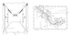
- FIG. 1is a fragmentary perspective view of the inside of a container (and specifically a refrigerated trailer), and illustrates two bulkheads each respectively attached to the container using a bulkhead tether apparatus of one embodiment of the present disclosure, and showing the bulkheads in upright storage positions adjacent to the respective opposing side walls of the container.
- FIG. 2is a fragmentary perspective view of the inside of the container of FIG. 1 , and illustrates the two bulkheads of FIG. 1 , each respectively attached to the container using a bulkhead tether apparatus of one embodiment of the present disclosure, and showing the bulkheads connected to each other in an upright in use position.
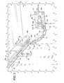
- FIG. 3is an enlarged fragmentary perspective view of a bulkhead tether apparatus of one embodiment of the present disclosure, shown attached to the inside of the container and to a bulkhead.
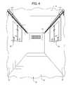
- FIG. 4is a fragmentary perspective view of the inside of a container (and specifically a refrigerated trailer), and illustrates two bulkheads each respectively attached to the container using a bulkhead tether apparatus of one embodiment of the present disclosure, and showing the bulkheads in substantially horizontally extending storage positions adjacent to the respective opposing side walls of the container.
- Various embodiments of the present disclosureprovide an easy to install bulkhead tether apparatus for securing bulkheads in containers such as refrigerated trailers.
- Various embodiments of the present disclosureare configured for bulkhead systems which include one or more pairs of bulkheads which in use are configured to extend across the container and be suitably attached by fasteners.
- the bulkhead tether apparatus 40 of the present disclosureis configured to be used in a container 10 with a bulkhead system including one or more pairs of bulkheads such as the pair of bulkheads 20 and 30 .
- FIG. 1illustrates the inside of the container 10 with the bulkheads 20 and 30 respectively attached by the bulkhead tether apparatus of the present disclosure (not shown in FIG. 1 ) adjacent to the side walls 12 and 13 of the container 10 .
- FIG. 1illustrates the bulkheads 20 and 30 in upright storage positions adjacent to the respective side walls 12 and 13 .
- FIG. 2illustrates the inside of the container 10 with the two bulkheads 20 and 30 respectively attached the side walls 12 and 13 of the container 10 by the bulkhead tether apparatus of the present disclosure (not shown in FIG. 2 ), and the bulkheads 20 and 30 in upright in-use positions extending across the container 10 .
- suitable fasteners 28 a , 28 b , 28 c , 38 a , 38 b , as 38 care used to releasably secure bulkheads 20 and 30 together.
- the fastenersmay be any suitable type of fasteners such a hook and loop type fasteners (commonly sold under the VELCRO® trademark).
- the bulkheads 20 and 30extend from the ceiling 14 to the floor 16 of the container 10 and from the side wall 12 to the side wall 13 .
- FIG. 4illustrates the inside of the container 10 with the bulkheads 20 and 30 respectively attached to the side walls 12 and 13 of the container 10 by one embodiment of the bulkhead tether apparatus of the present disclosure.
- the bulkheads 20 and 30are mounted in a substantially horizontally extending alternative storage positions which are off of the floor 16 of the container 10 .
- Two bulkhead tether apparatuses of the present disclosureare respectively used to attach the bulkheads 20 and 30 inside the container 10 .
- the two bulkhead tether apparatusesare identical in this embodiment, and thus only the bulkhead apparatus (generally indicated by numeral 40 in FIG. 3 ) used to attach bulkhead 30 adjacent to side wall 13 is discussed herein for brevity. It should be appreciated that the bulkhead tether apparatuses of the present disclosure do not need to be identical.
- the bulkhead tether apparatus 40 illustrated in FIG. 3generally includes: (a) a roller track 50 ; (b) a trolley 60 configured to be movably attached to or inside of the roller track 50 ; (c) a bulkhead bracket 80 securely attachable to the bulkhead 30 ; and (d) a relatively short chain 70 releasably attachable to the trolley 60 and releasably attachable to the bulkhead bracket 80 .
- the roller track 50is configured to be attached at the upper corner of the container 10 where the ceiling 14 meets the side wall 13 of the container 10 as shown in FIGS. 1, 2, 3, and 4 .
- the roller track 50is configured to be attached to the upper portion of the side wall 13 by a plurality of roller track attachment brackets such as roller track attachment bracket 52 which is shown in FIG. 3 attached to the side wall 13 .
- This illustrated roller track 50has a generally upside down U-shape and is configured to receive the trolley 60 as generally shown in FIG. 3 .
- the roller track 50include an elongated top wall (not shown) and two opposing spaced apart elongated L-shaped legs 54 and 56 integrally connected to and extending downwardly from the top wall.
- the L-shaped legs 54 and 56respectively include generally transversely, horizontally, or substantially horizontally extending elongated roller supports or tracks 54 a and 56 a configured to support the wheels or rollers 64 a , 64 b , 64 c , and 64 d of the trolley 60 .
- the elongated roller supports or tracks 54 a and 56 adefine an elongated opening 58 through which the stem 66 of the trolley 60 extends.
- One or more suitable stopping membersare attached to or mounted in the roller track 50 such as at or near one or more of the ends of the roller track 50 to prevent the trolley 60 from coming out of the roller track 50 on either end of the roller track 50 .
- the front end of the roller track 50can also be mounted adjacent to the front wall 15 inside of the container 10 to prevent the trolley 60 from coming out of the roller track 50 at that end.
- the roller trackis made from steel; however, the roller track can be made from any suitable materials and in any suitable size and shape.
- the trolley 60is configured to be movably mounted in the roller track 30 as generally shown in FIG. 3 .
- the trolley 60is configured to be inserted in the roller track 50 from one end of the track (before the stopping member is attached to the roller track 50 ) and be freely movable in the roller track 50 .
- the trolley 60includes a body 62 , four wheels or rollers 64 a , 64 b , 64 c , and 64 d rotatably attached to the body 62 , and a stem 66 extending downwardly from the body 62 .
- the stem 66defines an attachment opening 68 .
- the trolleyis made from aluminum and steel; however, the trolley can be made from any suitable materials and in any suitable size and shape so long as it is freely movable with respect to the roller track.
- roller track and trolleyare contemplated in accordance with the present disclosure.
- the bulkhead bracket 80is configured to be securely attached to the top of a bulkhead such as bulkhead 30 as generally shown in FIG. 3 .
- the bulkhead bracket 80generally includes a base 82 secured (by suitable fasteners 84 a, 84 b , 84 c , and 84 d ) to the bulkhead 30 adjacent to the upper corner of the bulkhead 30 .
- the bulkhead bracket 80further includes an engagement loop or ring 86 pivotably connected to the base 82 by bracket 88 which is secured to the base 82 by suitable fasteners 90 a and 90 b . This configuration enables the engagement loop or ring 86 to pivot in a horizontal or substantially horizontal direction.
- the bulkhead bracketis made from steel; however, the bulkhead bracket can be made from any suitable materials and in any suitable size and shape.
- the relatively short chain 70is configured to be releasably attachable to the trolley 60 and releasably attachable to the bulkhead bracket 80 as generally show in FIG. 3 .
- This illustrated chain 70includes a plurality of oblong closed links 72 a , 72 b , and 72 c , and a plurality of oblong openable links 76 and 78 .
- the openable link 76is openable to attach the chain 70 to the stem 66 of the trolley 60 , and closeable to secure the chain to the stem 66 of the trolley 60 as shown in FIG. 3 .
- the openable link 78is openable to attach the chain 70 to the engagement loop or ring 86 of the bulkhead bracket 80 , and closeable to secure the chain 70 to the engagement loop or ring 86 of the bulkhead bracket 80 as shown in FIG. 3 .
- the openable linksare carabineers with or without springs, although it should be appreciated that they may be in other forms.
- the length of the chain 70is relatively short and is selected to enable certain movements of the bulkhead 30 and to limit other movements of the bulkhead 30 , as further described below, and to ensure that the bulkhead 30 and the trolley 60 are separated by at most a predetermined distance.
- the chainis made from steel; however, the chain can be made from any suitable materials and in any suitable size and shape so long as it is freely movable with respect to the roller track and so long as it is within a designated length range.
- This combination of the roller track (including any stopping members), the trolley, relatively short chain, and bulkhead bracketprovides several advantages.
- This combinationis relatively inexpensive and relatively easy to install and repair, in part because it has relatively few parts, relatively less expensive parts, and is configured to be installed in a straightforward manner.
- This combinationenables the bulkhead to travel the length of the roller track, but prevents the bulkhead from being removed from the container.
- This combinationenables the bulkhead to be moved out of the way during loading and unloading in several different ways. In one way, this combination enables the bulkhead to swing 90 degrees forward from extending across the container (in an upright position as shown in FIG. 2 ) to extending adjacent to the side wall (in an upright position) as shown in FIG. 1 .
- this combinationenables the bulkhead to swing 90 degrees rearward from extending across the container (in an upright position as shown in FIG. 2 ) to extending adjacent to the side wall (in an upright position).
- this combinationenables the bulkhead to swing either forward or rearward to move out of the way when products are loaded into or unloaded from the container.
- This combinationalso enables the bulkhead to be moved completely out of the way and off of the floor 16 . After swinging adjacently to the side wall, this combination also enables the bulkhead to swing upwardly 90 degrees from an upright position against the side wall to a horizontally or substantially horizontally extending position adjacent to the side wall as shown in FIG. 4 .
- a second trolley 110 , second bulkhead bracket (not shown), and a line or rope (not shown)are employed in this embodiment to lift the bottom end of the bulkhead off of the floor 16 .
- the second trolley 110is movably mounted to or in the roller track 50 , the second bulkhead bracket is attached to the bottom corner of the bulkhead 30 , and the line or rope is releasably attached to the second trolley 110 or stem of the second trolley 110 and the second bulkhead bracket.
- the bulkhead tether apparatusincludes a second trolley, a second or lower bulkhead bracket, and line or rope.
- the bulkhead tether apparatusincludes a third trolley and a rope or line holder attached to the third trolley and configured to hold the rope or line out of the way.
Landscapes
- Engineering & Computer Science (AREA)
- Mechanical Engineering (AREA)
- Transportation (AREA)
- Loading Or Unloading Of Vehicles (AREA)
- Physics & Mathematics (AREA)
- Thermal Sciences (AREA)
- Health & Medical Sciences (AREA)
- Public Health (AREA)
Abstract
Description
Claims (22)
Priority Applications (1)
| Application Number | Priority Date | Filing Date | Title |
|---|---|---|---|
| US14/687,621US9566894B2 (en) | 2014-07-31 | 2015-04-15 | Bulkhead tether apparatus |
Applications Claiming Priority (2)
| Application Number | Priority Date | Filing Date | Title |
|---|---|---|---|
| US201462031589P | 2014-07-31 | 2014-07-31 | |
| US14/687,621US9566894B2 (en) | 2014-07-31 | 2015-04-15 | Bulkhead tether apparatus |
Publications (2)
| Publication Number | Publication Date |
|---|---|
| US20160031360A1 US20160031360A1 (en) | 2016-02-04 |
| US9566894B2true US9566894B2 (en) | 2017-02-14 |
Family
ID=55179168
Family Applications (1)
| Application Number | Title | Priority Date | Filing Date |
|---|---|---|---|
| US14/687,621ActiveUS9566894B2 (en) | 2014-07-31 | 2015-04-15 | Bulkhead tether apparatus |
Country Status (1)
| Country | Link |
|---|---|
| US (1) | US9566894B2 (en) |
Citations (22)
| Publication number | Priority date | Publication date | Assignee | Title |
|---|---|---|---|---|
| US1075961A (en)* | 1913-03-18 | 1913-10-14 | Charles H Blemer | Bulkhead for cars. |
| US3168055A (en)* | 1964-05-11 | 1965-02-02 | Unarco Industries | Movable bulkhead for railroad cars |
| US4168667A (en)* | 1977-08-01 | 1979-09-25 | Unarco Industries, Inc. | Curtain for lading protection |
| US5769704A (en) | 1996-08-21 | 1998-06-23 | Aero Industries, Inc. | Air return bulkhead for refrigeration trailers |
| US5807046A (en) | 1996-02-26 | 1998-09-15 | Onken; Greg | Air return bulkhead |
| US5947812A (en) | 1996-08-21 | 1999-09-07 | Henning; Steven A. | Air return bulkhead for refrigeration trailers |
| US6116044A (en) | 1999-04-27 | 2000-09-12 | Aero Industries, Inc. | Air chute adapter for refrigeration vehicles |
| US6305128B1 (en) | 2000-08-23 | 2001-10-23 | Illinois Tool Works, Inc. | Insulated bulkhead |
| US6877940B2 (en) | 2000-10-19 | 2005-04-12 | Fg Products, Inc. | Bulkhead and partition systems |
| US6945865B1 (en) | 2000-03-10 | 2005-09-20 | Illinois Tool Works, Inc. | Air return bulkhead |
| US7195435B2 (en) | 2004-01-27 | 2007-03-27 | Illinois Tool Works Inc. | Partition system |
| US7249921B2 (en) | 2004-03-24 | 2007-07-31 | Illinois Tool Works Inc. | Expandable/contractible universal thermal bulkhead structure for use within refrigerated cargo containers |
| US7300236B2 (en) | 2000-07-20 | 2007-11-27 | Fg Products, Inc. | Bulkhead lift apparatus |
| US20080190129A1 (en) | 2007-02-12 | 2008-08-14 | Illinois Tool Works Inc. | Header and chute attachment implements for header-chute assemblies of refrigeration systems |
| US7607874B2 (en) | 2000-07-20 | 2009-10-27 | Fg Products, Inc. | System and method for partitioning cargo areas |
| US20090320514A1 (en) | 2008-06-25 | 2009-12-31 | Toby Clark | Universal fluid flow transitional connector for use with refrigeration units of refrigerated trailers |
| US20110011122A1 (en) | 2009-07-17 | 2011-01-20 | Illinois Tool Works Inc. | Portable bulkhead for refrigeration containers |
| US7901168B2 (en)* | 2005-04-11 | 2011-03-08 | Fa-Kouri David C | Cargo anchoring system |
| US8087859B2 (en) | 2008-11-12 | 2012-01-03 | Fg Products, Inc. | Systems and methods for separating cargo spaces |
| US8298056B2 (en) | 2008-06-25 | 2012-10-30 | Illinois Tool Works Inc. | Air return bulkhead with removable panel for access to the lower region of a trailer refrigeration unit |
| US8834083B2 (en) | 2009-01-21 | 2014-09-16 | Fg Products, Inc. | Partitioning cargo spaces |
| US20140335775A1 (en) | 2013-05-13 | 2014-11-13 | Signode Industrial Group Llc | Refrigeration trailer air distribution chute |
- 2015
- 2015-04-15USUS14/687,621patent/US9566894B2/enactiveActive
Patent Citations (27)
| Publication number | Priority date | Publication date | Assignee | Title |
|---|---|---|---|---|
| US1075961A (en)* | 1913-03-18 | 1913-10-14 | Charles H Blemer | Bulkhead for cars. |
| US3168055A (en)* | 1964-05-11 | 1965-02-02 | Unarco Industries | Movable bulkhead for railroad cars |
| US4168667A (en)* | 1977-08-01 | 1979-09-25 | Unarco Industries, Inc. | Curtain for lading protection |
| US5807046A (en) | 1996-02-26 | 1998-09-15 | Onken; Greg | Air return bulkhead |
| US5993310A (en) | 1996-02-26 | 1999-11-30 | John Donovan Enterprises-Florida, Inc. | Air return bulkhead |
| US6203419B1 (en) | 1996-02-26 | 2001-03-20 | John Donovan Enterprises-Florida, Inc. | Air return bulkhead |
| US6626753B2 (en) | 1996-02-26 | 2003-09-30 | Illinois Tool Works Inc | Air return bulkhead |
| US6827534B2 (en) | 1996-02-26 | 2004-12-07 | Illinois Tool Works Ltd. | Air return bulkhead |
| US5769704A (en) | 1996-08-21 | 1998-06-23 | Aero Industries, Inc. | Air return bulkhead for refrigeration trailers |
| US5947812A (en) | 1996-08-21 | 1999-09-07 | Henning; Steven A. | Air return bulkhead for refrigeration trailers |
| US6116044A (en) | 1999-04-27 | 2000-09-12 | Aero Industries, Inc. | Air chute adapter for refrigeration vehicles |
| US6945865B1 (en) | 2000-03-10 | 2005-09-20 | Illinois Tool Works, Inc. | Air return bulkhead |
| US7600955B2 (en) | 2000-07-20 | 2009-10-13 | Fg Products, Inc. | Bulkhead lift apparatus and methods |
| US7607874B2 (en) | 2000-07-20 | 2009-10-27 | Fg Products, Inc. | System and method for partitioning cargo areas |
| US7300236B2 (en) | 2000-07-20 | 2007-11-27 | Fg Products, Inc. | Bulkhead lift apparatus |
| US6305128B1 (en) | 2000-08-23 | 2001-10-23 | Illinois Tool Works, Inc. | Insulated bulkhead |
| US6877940B2 (en) | 2000-10-19 | 2005-04-12 | Fg Products, Inc. | Bulkhead and partition systems |
| US7195435B2 (en) | 2004-01-27 | 2007-03-27 | Illinois Tool Works Inc. | Partition system |
| US7249921B2 (en) | 2004-03-24 | 2007-07-31 | Illinois Tool Works Inc. | Expandable/contractible universal thermal bulkhead structure for use within refrigerated cargo containers |
| US7901168B2 (en)* | 2005-04-11 | 2011-03-08 | Fa-Kouri David C | Cargo anchoring system |
| US20080190129A1 (en) | 2007-02-12 | 2008-08-14 | Illinois Tool Works Inc. | Header and chute attachment implements for header-chute assemblies of refrigeration systems |
| US20090320514A1 (en) | 2008-06-25 | 2009-12-31 | Toby Clark | Universal fluid flow transitional connector for use with refrigeration units of refrigerated trailers |
| US8298056B2 (en) | 2008-06-25 | 2012-10-30 | Illinois Tool Works Inc. | Air return bulkhead with removable panel for access to the lower region of a trailer refrigeration unit |
| US8087859B2 (en) | 2008-11-12 | 2012-01-03 | Fg Products, Inc. | Systems and methods for separating cargo spaces |
| US8834083B2 (en) | 2009-01-21 | 2014-09-16 | Fg Products, Inc. | Partitioning cargo spaces |
| US20110011122A1 (en) | 2009-07-17 | 2011-01-20 | Illinois Tool Works Inc. | Portable bulkhead for refrigeration containers |
| US20140335775A1 (en) | 2013-05-13 | 2014-11-13 | Signode Industrial Group Llc | Refrigeration trailer air distribution chute |
Also Published As
| Publication number | Publication date |
|---|---|
| US20160031360A1 (en) | 2016-02-04 |
Similar Documents
| Publication | Publication Date | Title |
|---|---|---|
| US10583847B2 (en) | Raisable carrying device | |
| JP6669408B2 (en) | Vehicle trailer system | |
| CA2754489C (en) | Auto-rack railroad car vehicle wheel chock hanger | |
| US7195435B2 (en) | Partition system | |
| KR101663218B1 (en) | A cargo box equipped with the guard rail of the cargo truck | |
| CN107074143B (en) | Haulage vehicle with the extension vertical structure for motro drivien handler | |
| US9566894B2 (en) | Bulkhead tether apparatus | |
| US2827958A (en) | Chain closure and partition for openings | |
| KR200484170Y1 (en) | Container for coil transportation | |
| US20040005204A1 (en) | Bulkhead lift apparatus | |
| CN104477223B (en) | Novel multifunctional trailer for field operations | |
| US20170144610A1 (en) | Kayak carrier for vehicle hitch | |
| KR200479416Y1 (en) | Died pig shifter in pigsty | |
| CN104512444B (en) | Combination structure of field multifunctional trailer and trailer guide rail that can be overlapped | |
| JP2015116842A (en) | Container transport vehicle | |
| CN204341135U (en) | The field operations Multifunction tow that can overlap and trailer guide rail | |
| KR102480345B1 (en) | Removable guard unit for lift gate of cargo truck | |
| CN204341134U (en) | A kind of novel field operations Multifunction tow | |
| RU148966U1 (en) | COMBINED WAGON (OPTIONS) | |
| US7878575B1 (en) | Trailer with sliding safety door | |
| AU2008100477B4 (en) | Utility motor vehicle. Tray divider | |
| JP2008087657A (en) | Mounting type vehicle transporter | |
| AU2011101694A4 (en) | Adjustable cargo barrier system | |
| BE1020593A3 (en) | DEVICE FOR LOADING, UNLOADING AND TIPPING OUT CONTAINERS AND SUCH AND VEHICLE EQUIPPED WITH SUCH DEVICE. | |
| RU2545246C1 (en) | Automotive support structure |
Legal Events
| Date | Code | Title | Description |
|---|---|---|---|
| AS | Assignment | Owner name:SIGNODE INDUSTRIAL GROUP LLC, ILLINOIS Free format text:ASSIGNMENT OF ASSIGNORS INTEREST;ASSIGNOR:CLARK, TOBY W.;REEL/FRAME:035451/0177 Effective date:20140829 | |
| STCF | Information on status: patent grant | Free format text:PATENTED CASE | |
| AS | Assignment | Owner name:DEUTSCHE BANK AG NEW YORK BRANCH, AS COLLATERAL AGENT, NEW YORK Free format text:SECURITY AGREEMENT;ASSIGNOR:SIGNODE INDUSTRIAL GROUP LLC;REEL/FRAME:045833/0485 Effective date:20180403 Owner name:DEUTSCHE BANK AG NEW YORK BRANCH, AS COLLATERAL AG Free format text:SECURITY AGREEMENT;ASSIGNOR:SIGNODE INDUSTRIAL GROUP LLC;REEL/FRAME:045833/0485 Effective date:20180403 | |
| MAFP | Maintenance fee payment | Free format text:PAYMENT OF MAINTENANCE FEE, 4TH YEAR, LARGE ENTITY (ORIGINAL EVENT CODE: M1551); ENTITY STATUS OF PATENT OWNER: LARGE ENTITY Year of fee payment:4 | |
| AS | Assignment | Owner name:SIGNODE INDUSTRIAL GROUP LLC, ILLINOIS Free format text:RELEASE BY SECURED PARTY;ASSIGNOR:DEUTSCHE BANK AG NEW YORK BRANCH;REEL/FRAME:065564/0736 Effective date:20231113 Owner name:CROWN PACKAGING TECHNOLOGY, INC., ILLINOIS Free format text:RELEASE BY SECURED PARTY;ASSIGNOR:DEUTSCHE BANK AG NEW YORK BRANCH;REEL/FRAME:065564/0736 Effective date:20231113 | |
| MAFP | Maintenance fee payment | Free format text:PAYMENT OF MAINTENANCE FEE, 8TH YEAR, LARGE ENTITY (ORIGINAL EVENT CODE: M1552); ENTITY STATUS OF PATENT OWNER: LARGE ENTITY Year of fee payment:8 |