US9566594B2 - Adhesive applicator - Google Patents
Adhesive applicatorDownload PDFInfo
- Publication number
- US9566594B2 US9566594B2US14/296,666US201414296666AUS9566594B2US 9566594 B2US9566594 B2US 9566594B2US 201414296666 AUS201414296666 AUS 201414296666AUS 9566594 B2US9566594 B2US 9566594B2
- Authority
- US
- United States
- Prior art keywords
- adhesive
- tray
- package
- applicator
- carrier
- Prior art date
- Legal status (The legal status is an assumption and is not a legal conclusion. Google has not performed a legal analysis and makes no representation as to the accuracy of the status listed.)
- Active, expires
Links
Images


Classifications
- B—PERFORMING OPERATIONS; TRANSPORTING
- B05—SPRAYING OR ATOMISING IN GENERAL; APPLYING FLUENT MATERIALS TO SURFACES, IN GENERAL
- B05B—SPRAYING APPARATUS; ATOMISING APPARATUS; NOZZLES
- B05B9/00—Spraying apparatus for discharge of liquids or other fluent material, without essentially mixing with gas or vapour
- B05B9/007—At least a part of the apparatus, e.g. a container, being provided with means, e.g. wheels, for allowing its displacement relative to the ground
- B—PERFORMING OPERATIONS; TRANSPORTING
- B05—SPRAYING OR ATOMISING IN GENERAL; APPLYING FLUENT MATERIALS TO SURFACES, IN GENERAL
- B05B—SPRAYING APPARATUS; ATOMISING APPARATUS; NOZZLES
- B05B13/00—Machines or plants for applying liquids or other fluent materials to surfaces of objects or other work by spraying, not covered by groups B05B1/00 - B05B11/00
- B05B13/005—Machines or plants for applying liquids or other fluent materials to surfaces of objects or other work by spraying, not covered by groups B05B1/00 - B05B11/00 mounted on vehicles or designed to apply a liquid on a very large surface, e.g. on the road, on the surface of large containers
- B—PERFORMING OPERATIONS; TRANSPORTING
- B05—SPRAYING OR ATOMISING IN GENERAL; APPLYING FLUENT MATERIALS TO SURFACES, IN GENERAL
- B05C—APPARATUS FOR APPLYING FLUENT MATERIALS TO SURFACES, IN GENERAL
- B05C11/00—Component parts, details or accessories not specifically provided for in groups B05C1/00 - B05C9/00
- B05C11/10—Storage, supply or control of liquid or other fluent material; Recovery of excess liquid or other fluent material
- B05C11/1044—Apparatus or installations for supplying liquid or other fluent material to several applying apparatus or several dispensing outlets, e.g. to several extrusion nozzles
- B—PERFORMING OPERATIONS; TRANSPORTING
- B05—SPRAYING OR ATOMISING IN GENERAL; APPLYING FLUENT MATERIALS TO SURFACES, IN GENERAL
- B05C—APPARATUS FOR APPLYING FLUENT MATERIALS TO SURFACES, IN GENERAL
- B05C17/00—Hand tools or apparatus using hand held tools, for applying liquids or other fluent materials to, for spreading applied liquids or other fluent materials on, or for partially removing applied liquids or other fluent materials from, surfaces
- B05C17/005—Hand tools or apparatus using hand held tools, for applying liquids or other fluent materials to, for spreading applied liquids or other fluent materials on, or for partially removing applied liquids or other fluent materials from, surfaces for discharging material from a reservoir or container located in or on the hand tool through an outlet orifice by pressure without using surface contacting members like pads or brushes
- B05C17/00553—Hand tools or apparatus using hand held tools, for applying liquids or other fluent materials to, for spreading applied liquids or other fluent materials on, or for partially removing applied liquids or other fluent materials from, surfaces for discharging material from a reservoir or container located in or on the hand tool through an outlet orifice by pressure without using surface contacting members like pads or brushes with means allowing the stock of material to consist of at least two different components
- B—PERFORMING OPERATIONS; TRANSPORTING
- B05—SPRAYING OR ATOMISING IN GENERAL; APPLYING FLUENT MATERIALS TO SURFACES, IN GENERAL
- B05C—APPARATUS FOR APPLYING FLUENT MATERIALS TO SURFACES, IN GENERAL
- B05C17/00—Hand tools or apparatus using hand held tools, for applying liquids or other fluent materials to, for spreading applied liquids or other fluent materials on, or for partially removing applied liquids or other fluent materials from, surfaces
- B05C17/005—Hand tools or apparatus using hand held tools, for applying liquids or other fluent materials to, for spreading applied liquids or other fluent materials on, or for partially removing applied liquids or other fluent materials from, surfaces for discharging material from a reservoir or container located in or on the hand tool through an outlet orifice by pressure without using surface contacting members like pads or brushes
- B05C17/00576—Hand tools or apparatus using hand held tools, for applying liquids or other fluent materials to, for spreading applied liquids or other fluent materials on, or for partially removing applied liquids or other fluent materials from, surfaces for discharging material from a reservoir or container located in or on the hand tool through an outlet orifice by pressure without using surface contacting members like pads or brushes characterised by the construction of a piston as pressure exerting means, or of the co-operating container
- B—PERFORMING OPERATIONS; TRANSPORTING
- B05—SPRAYING OR ATOMISING IN GENERAL; APPLYING FLUENT MATERIALS TO SURFACES, IN GENERAL
- B05C—APPARATUS FOR APPLYING FLUENT MATERIALS TO SURFACES, IN GENERAL
- B05C17/00—Hand tools or apparatus using hand held tools, for applying liquids or other fluent materials to, for spreading applied liquids or other fluent materials on, or for partially removing applied liquids or other fluent materials from, surfaces
- B05C17/005—Hand tools or apparatus using hand held tools, for applying liquids or other fluent materials to, for spreading applied liquids or other fluent materials on, or for partially removing applied liquids or other fluent materials from, surfaces for discharging material from a reservoir or container located in or on the hand tool through an outlet orifice by pressure without using surface contacting members like pads or brushes
- B05C17/00589—Hand tools or apparatus using hand held tools, for applying liquids or other fluent materials to, for spreading applied liquids or other fluent materials on, or for partially removing applied liquids or other fluent materials from, surfaces for discharging material from a reservoir or container located in or on the hand tool through an outlet orifice by pressure without using surface contacting members like pads or brushes comprising a guiding rotating element, e.g. a wheel
- B—PERFORMING OPERATIONS; TRANSPORTING
- B05—SPRAYING OR ATOMISING IN GENERAL; APPLYING FLUENT MATERIALS TO SURFACES, IN GENERAL
- B05C—APPARATUS FOR APPLYING FLUENT MATERIALS TO SURFACES, IN GENERAL
- B05C5/00—Apparatus in which liquid or other fluent material is projected, poured or allowed to flow on to the surface of the work
- B05C5/02—Apparatus in which liquid or other fluent material is projected, poured or allowed to flow on to the surface of the work the liquid or other fluent material being discharged through an outlet orifice by pressure, e.g. from an outlet device in contact or almost in contact, with the work
- B05C5/027—Coating heads with several outlets, e.g. aligned transversally to the moving direction of a web to be coated
- B05C5/0275—Coating heads with several outlets, e.g. aligned transversally to the moving direction of a web to be coated flow controlled, e.g. by a valve
- B05C5/0279—Coating heads with several outlets, e.g. aligned transversally to the moving direction of a web to be coated flow controlled, e.g. by a valve independently, e.g. individually, flow controlled
- E—FIXED CONSTRUCTIONS
- E04—BUILDING
- E04D—ROOF COVERINGS; SKY-LIGHTS; GUTTERS; ROOF-WORKING TOOLS
- E04D15/00—Apparatus or tools for roof working
- E04D15/07—Apparatus or tools for roof working for handling roofing or sealing material in bulk form
Definitions
- the present inventionrelates to an applicator for dispensing an all weather adhesive on a roofing substrate, and more particularly to an applicator for dispensing an all weather two-part adhesive.
- a roofing membraneis used to seal and protect the roof deck from environmental weather conditions.
- the roofing membranemay be made of various materials, such as polymeric materials including EPDM (ethylene propylene diene M-rubber) or TPO (thermoplastic polyolefin).
- EPDMethylene propylene diene M-rubber
- TPOthermoplastic polyolefin
- the roofing membraneis adhered overtop insulation boards or panels.
- the insulation boardsare typically secured to the roofing substrate or roof deck via an adhesive composition.
- a conventional adhesive composition used to adhere the insulation boards to the roof deckincludes polyurethane.
- the polyurethane adhesivesare oftentimes applied directly onto the roof deck via an applicator system and the insulation boards are then laid onto the roof deck surface.
- Conventional polyurethane adhesivesoftentimes include two separate parts that are mixed by an applicator just prior to being applied onto the surface of the roof deck.
- the two partsinclude an isocyanate blend and a simple polyol blend.
- the isocyanate blendreacts or crosslinks with the simple polyol blend to form the polyurethane adhesive.
- conventional two-part polyurethane adhesivesare sensitive to weather conditions due to the effects of temperature on the viscosity, and therefore the reaction speed, of the adhesive. Accordingly, conventional two-part polyurethane adhesives are packaged and formulated into various grades, such as Summer, Winter, and Regular, that vary the composition of the adhesive in order to account for temperature.
- a device for applying a two-part adhesive to a substrateincludes a carrier, a first tray coupled to the carrier, a first package disposed in the first tray, and a second package disposed in the first tray.
- the first packagecontains a first part of the two-part adhesive and the second package contains a second part of the two-part adhesive.
- the devicefurther includes a applicator that is in communication with the first package and the second package. The applicator is configured to receive the first part and the second part and mix the first part and the second part to form the two-part adhesive.
- the devicealso includes a second tray coupled to the carrier and configured to accommodate a power supply that provides electrical power to operate the device.
- FIG. 1is a front view of a device for applying a two-part adhesive
- FIG. 2is a front perspective view of the device
- FIG. 3is a schematic diagram of the device
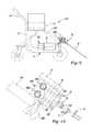
- FIG. 4is a view of a portion of the device showing a prime mover and gear box connection
- FIG. 5is a side view of a manifold used with the device
- FIG. 6is a front view of a connector used with the device
- FIG. 7is a front view of another connector used with the device.
- FIG. 8is an exploded side view of the connectors shown in FIGS. 6 and 7 with a removable wand;
- FIG. 9is a side view of another embodiment of the device.
- FIG. 10is a side view of another manifold used with the device.
- FIG. 11Ais front view of a manifold used with the device
- FIG. 11Bis a front view of a portion of the manifold shown in FIG. 11A ;
- FIG. 12is a top view of connectors used with the device.
- FIG. 13is a side view of another embodiment of the device.
- FIG. 14is a side view of a portion of the device
- FIG. 15is a connection diagram of the device
- FIG. 16is a partial view of a connection of the device
- FIG. 17is a view of a portion of the device
- FIG. 18is a view of another portion of the device.
- FIG. 19is a schematic diagram of a control system used with the device.
- FIG. 20is a flow chart illustrating a method of controlling the device
- FIG. 21is a schematic top view of an interlocking system used with the device.
- FIG. 22is a top view of an embodiment of the interlocking system used with the device.
- FIG. 23is a perspective view of an embodiment of a device according to the principles of the present invention.
- FIG. 24is a top view of a portion of the device shown in FIG. 23 ;
- FIG. 25is a perspective view of another device for applying a two-part adhesive
- FIG. 26is a perspective view of yet another device for applying a two-part adhesive
- FIG. 27is perspective view of yet another device for applying a two-part adhesive
- FIG. 28shows the device of FIG. 27 with an applicator
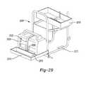
- FIG. 29shows a tray associated with the device of FIG. 27 ;
- FIGS. 30 and 31show a close-up view of the tray shown in FIG. 29 .
- a device for applying a two-part fluid to a substrateis generally indicated by reference number 10 .
- the device 10includes a carrier or frame 12 .
- the carrier or frame 12is used to support the various components of the device 10 and may take many forms without departing from the scope of the present invention.
- the carrier 12includes a rectangular base 14 with an upwardly extending portions or support columns 16 .
- the rectangular portionincludes two rotatable front wheels 18 A and two spindle mounted back wheels 18 B. Back wheels 18 B are pivotable and rotatable allowing the device 10 to move forward as well as turn and rotate.
- the portion 16supports an upper frame 20 .
- a handle portion 24extends out from the upper frame 20 or alternatively from the portion 16 of the frame 12 .
- the upper frame 20is sized to receive two parts of a two-part compound 21 . These two parts are packaged separately and include an “A” side package 22 A and a “B” side package 22 B. Each of the packages 22 A, 22 B includes an outer box or container 25 A, 25 B that surrounds a collapsible bag 27 A, 27 B, respectively. The bags 27 A, 27 B each include an opening or nozzle 29 A, 29 B, respectively.
- This packaging systemis known as Cubitainer® manufactured by Hedwin Corporation, Baltimore, Md.
- Each of the bags 27 A, 27 Bpreferably contain one part of a two part all weather polyurethane adhesive for use on roofing substrates.
- the “A” sideincludes an isocyanate blend and the “B” side includes a polyol blend.
- the isocyanate blendreacts or crosslinks with the polyol blend to form the polyurethane adhesive.
- the bag 27 Ais fluorinated in order to prevent moisture penetration.
- the openings 29 A, 29 Bare shipped and stored with removable caps (not shown). When the caps are removed, the two parts of the polyurethane adhesive are exposed to moisture in the atmosphere.
- the isocyanate blendis preferably comprised of less than about 33% isocyanate by weight.
- An exemplary isocyanate blend for use with the two part adhesiveincludes RUBINATE M, manufactured by Huntsman. An isocyanate blend of approximately 31% isocyanate was placed under Brookfield and ran continuously for one hour at a spindle speed of 20 rpms. The following tables summarize the viscosity test results:
- the openings 29 A, 29 Bare connected to the device 10 after the caps are removed, as will be described in greater detail below.
- the upper frame 20is designed to accommodate a particular package configuration of the A side 22 A and the B side 22 B. While in the example provided the A side 22 A and B side 22 B are illustrated as having a rectangular box packaging system, it should be appreciated that other shaped packaging systems may be supported by the upper frame 20 .
- the device 10includes a prime mover 30 fixed or otherwise connected to the carrier 12 .
- the prime mover 30is preferably an electric motor, though it should be appreciated that the prime mover 30 may be any type of engine, such as a combustion engine, without departing from the scope of the present invention.
- the prime mover 30is connected to a gear box 32 via a rotatable shaft 34 .
- the gear box 32is fixed or otherwise connected to the carrier 12 .
- the gearbox 32transfers torque from the prime mover 30 to first and second rotatable shafts 34 A and 34 B.
- the rotatable shafts 35 A and 35 Bare coupled to a first and second pump 36 A and 36 B, respectively.
- Each pump 36 A and 36 Bincludes an inlet 38 A and 38 B, respectively, and an outlet 40 A and 40 B, respectively.
- the prime mover 30may be connected to the wheels 18 B or 18 A to provide a self-propelled configuration for the device 10 controlled by a throttle (not shown).
- the inlet 38 Ais connected via a hose or other fluid passage 42 A to the opening 29 A of the A side package 22 A of the two-part compound 21 .
- the hose 42 Ais connected to a quarter turn connector 44 A connected to the opening 29 A located on a bottom of the A side package 22 A.
- the connector 44 Aextends through an opening in the bottom of the upper frame 20 .
- the inlet 38 Bis connected via a hose or other fluid passage 42 B to the opening 29 B in the B side package 22 B of the two-part compound 21 .
- the hose 42 Bis connected to a quarter turn connector 44 B connected to the opening 29 B located on a bottom of the B side package 22 B.
- the connector 44 Bextends through the opening in the bottom of the upper frame 20 .
- the connectors 44 A, 44 Bmay be keyed connectors such that the connector 44 A can only connect to the hose 42 A and the connector 44 B can only connect to the hose 44 B, thereby preventing switching the A and B packages 22 A, 22 B on the device 10 .
- the outlet 40 A of the pump 36 Ais connected via hose or other type of fluid passage 46 A to an accumulator 50 A and a manifold 52 A.
- the accumulator 50 Ais an energy storage device in which a non-compressible fluid is held under pressure by an external source.
- the accumulator 50 Ais a gas filled type accumulator having a compressible gas that acts on a bladder within the accumulator to provide a compressive force on fluid within the accumulator 50 A.
- the accumulator 50 Amay be of other types, such as a spring type, without departing from the scope of the present invention.
- the manifold 52 Ais attached to a front of the upper frame 20 .
- the manifold 52 Aincludes an inlet port 60 A that connects with the hose 46 A.
- the manifold 52 Aincludes an inlet port 60 A that communicates with a bore 62 A that extends through the manifold 52 A.
- a ball valve 64 Ais preferably disposed within the inlet port 60 A and connects the hose 46 A with the bore 62 A.
- the bore 62 Acommunicates with a plurality of perpendicularly extending side bores 66 A.
- the side bores 66 Aeach communicate with an outlet port 68 A on the manifold 52 A. In the example provided, there are seven side bores 66 A and seven outlet ports 68 A. However, it should be appreciated that any number of side bores 66 A and outlet ports 68 A may be employed without departing from the scope of the present invention.
- Each of the outlet ports 68 Amay be optionally connected to one of a plurality of applicator units 70 via hoses or other fluid passages 72 A.
- four applicator units 70are illustrated with four hoses 72 A connecting each of the applicator units 70 with one of the outlet ports 68 A.
- the manifold 52 Acan accommodate up to seven applicator units 70 .
- the manifold 52 Aallows each applicator unit 70 to receive a flow of “A” side fluid from the “A” side package 22 A.
- the outlet 40 B of the pump 36 Bis connected via hose or other type of fluid passage 46 B to an accumulator 50 B and a manifold 52 B.
- the accumulator 50 Bis an energy storage device in which a non-compressible fluid is held under pressure by an external source.
- the accumulator 50 Bis a gas filled bladder type accumulator having a compressible gas that provides a compressive force on fluid via the bladder within the accumulator 50 B.
- the accumulator 50 Bmay be of other types, such as a spring type, without departing from the scope of the present invention.
- the manifold 52 Bis attached to a front of the frame 20 .
- the manifold 52 Bincludes an inlet port 60 B that connects with the hose 46 B.
- the manifold 52 Bincludes an inlet port 60 B that communicates with a bore 62 B that extends through the manifold 52 B.
- a ball valve 64 Bis preferably disposed within the inlet port 60 B and connects the hose 46 B with the bore 62 B.
- the bore 62 Bcommunicates with a plurality of perpendicularly extending side bores 66 B.
- the side bores 66 Beach communicate with an outlet port 68 B on the manifold 52 B. In the example provided, there are seven side bores 66 B and seven outlet ports 68 B. However, it should be appreciated that any number of side bores 66 B and outlet ports 68 B may be employed without departing from the scope of the present invention.
- Each of the outlet ports 68 Bmay be optionally connected to one of a plurality of the applicator units 70 via hoses or other fluid passages 72 B.
- the four applicator units 70are illustrated with four hoses 72 B connecting each of the applicator units 70 with one of the outlet ports 68 B.
- the manifold 52 Bcan accommodate up to up to seven applicator units 70 .
- the manifold 52 Ballows each applicator unit 70 to receive a flow of “B” side fluid from the “B” side package 22 B. separately from the fluid from the “A” side package 22 A.
- the applicator units 70are mounted on a front beam 71 attached to the carrier 12 and each applicator unit 70 includes a rotary valve 72 , a dual manifold 74 , an orifice restrictor 76 , and a nozzle 78 .
- the rotary valve 72includes an inlet port 80 A and an inlet port 80 B.
- the inlet port 80 Ais connected with the hose 72 A to receive “A” side fluid and the inlet port 80 B is connected with the hose 72 B to receive “B” side fluid.
- the inlet port 80 Acommunicates with a bore 82 A and the inlet port 80 B communicates with a bore 82 B.
- the bores 82 A and 82 Bare separate and do not communicate with one another. Each bore 82 A and 82 B extend through the rotary valve 72 parallel to one another.
- a shaft bore 84is located in the rotary valve and perpendicularly intersects both the bores 82 A and 82 B.
- a rotatable shaft 86is disposed within the shaft bore 84 .
- the rotatable shaft 86includes two spaced apart holes 88 A and 88 B that extend through the diameter of the shaft 86 .
- the spaced apart holes 88 A and 88 Bare in alignment with the bores 82 A and 82 B, respectively.
- the shaft 86is connected to a lever 90 .
- the shaft 86may be connected via a rigid or wire connection to a lever or other device connected with the handle 24 of the carrier 12 .
- the rotary valve 72is operable to throttle the fluid flow of the “A” and “B” side fluids through the applicator unit 70 .
- the rotary valve 72further includes bolt channel outlet ports 92 A and 92 B that communicate with the bores 82 A and 82 B, respectively.
- the dual manifold 74includes a body portion 94 and a neck portion 96 that extends out from the body portion 94 .
- the dual manifold 74includes inlet ports 96 A and 96 B that are connected to the bolt outlet ports 92 A and 92 B, respectively, of the rotary valve 72 .
- the inlet ports 96 A and 96 Bcommunicate with separate channels or bores 98 A and 98 B, respectively, that communicate through the body portion 94 and into the neck portion 96 to outlet ports 100 A and 100 B, respectively.
- the orifice restrictor 76is sealingly engaged to the neck portion 96 of the dual manifold 74 .
- the orifice restrictor 76includes a first orifice 102 A and a second orifice 102 B that communicate with the outlet ports 100 A and 100 B, respectively.
- the orifices 102 A and 102 Bare separate and do not communicate with each other.
- the orifice restrictor 76includes a slot 104 sized to receive a tab member 106 located on the neck portion 96 of the dual manifold 74 , as shown in FIGS. 6 and 7 .
- the tab member 106assures that the first orifice 102 A and the second orifice 102 B do not communicate.
- the first orifice 102 Ahas a diameter different than the second orifice 102 B.
- the first orifice 102 Ahas a diameter that is a function of the material characteristics of the composition of the “A” side fluid.
- the second orifice 102 Bhas a diameter that is a function of the material characteristics of the composition of the “B” side fluid.
- the orifices 102 A and 102 Bassure that fluid does not backflow into the dual manifold 74 , as will be described below.
- the orifices 102 A, 102 Ballow high viscosity compound to be ported therethrough. Combined with the configuration of the pumps 36 A and 36 B, the device 10 is operable to pump compounds having viscosities higher than 2500 Pas, and preferably as high as about 7000 Pas.
- the nozzle 78is an extended member that mixes the “A” side fluid with the “B” side fluid.
- the nozzle 78is coupled to the orifice restrictor 76 and communicates with the orifices 102 A and 102 B.
- the nozzle 78is disposable and is preferably a 36 element mixing nozzle, though it should be appreciated that other types and grades of nozzles may be employed without departing from the scope of the present invention.
- the operation of the device 10will now be described.
- An operator of the device 10activates the prime mover 30 which in turn drives the pumps 36 A and 36 B.
- the pumps 36 A and 36 Bsuck fluid from the “A” and “B” side packages 22 A and 22 B via hoses 42 A and 42 B, respectively.
- “A” side fluidexits the pump 36 A via outlet port 40 A and enters the hose 46 A.
- An amount of “A” side fluidenters the accumulator 50 A and charges the accumulator 50 A.
- the accumulator 50 Apreferably stores the fluid at approximately 300 psi.
- the remaining “A” side fluidenters the manifold 52 A and is communicated through the central bore 62 A to the side bores 66 A.
- the “A” side fluidthen exits the manifold 52 A and communicates via hose 72 A to the rotary valve 74 of the applicator unit 70 .
- the “A” side fluidcommunicates through the rotary valve 74 and is throttled based on the rotational position of the shaft 86 .
- the “A” side fluidexits the rotary valve 74 , communicates through the dual manifold 76 and the orifice restrictor 76 and enters the nozzle 78 for mixing.
- “B” side fluidexits the pump 36 B via outlet port 40 B and enters the hose 46 B.
- An amount of “B” side fluidenters the accumulator 50 B and charges the accumulator 50 B.
- the accumulator 50 Bpreferably stores the fluid at approximately 300 psi.
- the remaining “B” side fluidenters the manifold 52 B and is communicated through the central bore 62 B to the side bores 66 B.
- the “B” side fluidthen exits the manifold 52 B and communicates via hose 72 B to the rotary valve 74 of the applicator unit 70 .
- the “B” side fluidcommunicates through the rotary valve 74 and is throttled based on the rotational position of the shaft 86 .
- the “B” side fluidexits the rotary valve 74 , communicates through the dual manifold 76 and the orifice restrictor 76 and enters the nozzle 78 for mixing with the “A” side fluid.
- the mixed adhesiveis then dispensed from the nozzle 78 onto a substrate.
- the orifice restrictor 76 and the nozzle 78are disposable, it is desirable that the dual manifold 74 and rotary valve 76 do not become clogged with mixed and cured fluid. However, once the device 10 is deactivated, mixed fluid within the nozzle 78 may cure and expand, forcing mixed fluid back towards the orifice restrictor 76 . However, as the pumps 36 A and 36 B are deactivated, the accumulators 50 A and 50 B begin to discharge, providing a positive pressure of fluid back towards the orifice restrictor 76 . The back pressure provided by the accumulators 50 A and 50 B, in conjunction with the sizes of the orifices 102 A and 102 B, prevent mixed material within the nozzle 78 from entering the dual manifold 74 .
- an alternate embodiment of the device 10is generally indicated by reference number 200 .
- the device 200is similar to the device 10 described in FIGS. 1-8 , and therefore like components are indicated by like reference numbers.
- the device 200includes at least one dual channel manifold 202 .
- the dual channel manifold or adapter base plate 202is located on a forward support member 204 of the carrier 12 .
- the dual channel manifold 202includes a pair of inlet ports 206 A located on opposite ends of the manifold 202 and a pair of inlet ports 206 B located on opposite ends of the manifold.
- the inlet ports 206 Acommunicate with a first bore 208 A that extends along a length of the manifold 202 .
- the inlet ports 206 Bcommunicate with a second bore 208 B that extends along the length of the manifold 202 parallel to the first bore 208 A.
- the manifold 202includes side bores 210 A that communicate with the first bore 208 A and with outlets 212 A located along the length of the manifold 202 .
- the manifold 202includes side bores 210 A that communicate with the first bore 208 A and with outlets 212 A located along the length of the manifold 202 .
- One of the inlets 206 Ais connected with the hose 46 A while the opposite inlet 206 A is plugged.
- One of the inlets 206 Bis connected with the hose 46 B while the opposite inlet 206 B is plugged.
- the outlets 212 Acommunicate directly with the inlets 80 A of the rotary valves 76 and the outlets 212 B communicate directly with the inlets 80 B of the rotary valves 76 . Accordingly, each applicator unit 70 is fed “A” and “B” side fluids separately directly from the manifold 202 .
- FIG. 13yet another alternate embodiment of the device 10 is generally indicated by reference number 300 .
- the device 300is similar to the device 10 described in FIGS. 1-8 , and therefore like components are indicated by like reference numbers.
- the device 300replaces the accumulators 50 A and 50 B with one or more flow dividers 302 and replaces the rotary valves 72 with a plurality of diverter valves 304 A and 304 B, and adds an adaptor plate 306 positioned between the plurality of diverter valves 304 A and 304 B and the plural component or dual manifolds 74 .
- the present inventioncontemplates that in other embodiments of the invention additional flow dividers 302 , diverter valves 304 A, 304 B and adaptor plates 306 than are illustrated in the Figures are utilized.
- the flow dividers 302include dividers 302 A and 302 B to receive “A” and “B” side fluids, respectively.
- Flow dividers 302 A, 302 Bhave a single input port 310 and a plurality of output ports 312 .
- the number of output ports 312depends on the number of diverter valves 304 A, 304 B and mixing nozzles 78 desired.
- the flow dividers 302 A, 302 Bare connected to pumps 36 A, 36 B via lines 46 A, 46 B and four port couplings 314 A and 314 B.
- the flow dividers 302 A, 302 Buniformly divide flow of fluid from the input port 310 to the plurality of output ports 312 .
- each of the output portswill have the same flow rate. Since each individual divider output port flow rate is uniform, if one output is blocked the others will also stop flow in response.
- the present inventioncontemplates that flow dividers 302 A, 302 B have different number and sized output ports.
- diverters 304 A and 304 Bare matched to the number of output ports on flow dividers 302 A and 302 B. Diverters 304 A and 304 B are three way ball valves that may be actuated to completely shut of fluid flow to a particular nozzle 78 . Diverters 304 A and 304 B receive fluid from the outlet ports 312 of the flow dividers 302 A, 302 B and communicate the fluid to the adaptor plates 306 via a plurality of feed lines 308 A, 308 B.
- the adaptor plate 306is connectable to the dual manifold 74 described in the previous embodiments. More specifically, adapter plate 306 includes two fluid passages or bores 309 A, 309 B for communicating fluid from feed lines 308 A, 308 B to each of the bores of dual manifold 74 .
- a fluid by pass 316is provided to communicate fluid from the diverters 304 A, 304 B to inlet 310 .
- the redirection or bypass of fluid flow through fluid by pass 316 from the inlet 310 of the divider to the outlet 312 of the dividerkeeps the fluid flow through the outlet ports of the divider all uniform when an individual nozzle does not have any or the same flow rate as the other nozzles.
- the present embodimentfurther includes a two way ball valve 320 connected to the four way ball valve 314 .
- Valve 320allows fluid to be diverted to a hand held gun or similar bead dispenser (not shown).
- the bead dispensermay be connected to the end of a length of hose and the other end of the hose connected to the valve 320 .
- a single bead dispensed through the gunallows the operator to apply an adhesive in congested areas where the dispensing cart simply will not fit.
- the present embodimentincludes a quick release mixing nozzle 78 for faster change-outs.
- the quick release mixer nozzlehas restriction orifice 76 integrated into the nozzle.
- the mixer nozzle 78is configured to be quickly releasable from dual manifold 74 by eliminating the threads and attaching the nozzle to the dual manifold 74 via a latch 330 or similar device, as shown in FIG. 19 .
- a latch 330is available from SouthCo of Concordville, Pa.
- the quick release mixer nozzleis an improvement over the industry standard which is a threaded attachment of the mixing nozzle to the dual manifold 74 . Threaded nozzles are not preferred since they can easily get gummed up with adhesive and require cleaning.
- FIG. 19the device 10 is illustrated schematically with either the “A” side package 22 A or the “B” side package 22 B.
- An outlet line 402is coupled to the package 22 A, 22 B through which the compound within the package 22 A, 22 B is drawn by the pump 36 A, 36 B.
- Each individual package 22 A, 22 Bincludes an identifier 404 .
- the identifier 404is used to uniquely identify the particular package 22 A, 22 B.
- the identifier 404may be located in various locations, for example on an inside or outside of the package 22 A, 22 B, embedded within the package 22 A, 22 B, located within, or attached to, a bag within the package 22 A, 22 B, or within the adhesive compounds themselves.
- the device 10includes a reader 406 .
- the reader 406communicates with the identifier 404 through various methods, as will be described below.
- the identifier 406in turn is in electrical communication with a controller 408 .
- the controller 408is preferably an electronic control device having a preprogrammed digital computer or processor, control logic, memory used to store data, and at least one I/O peripheral.
- the control logicincludes a plurality of logic routines for monitoring, manipulating, and generating data.
- the controller 408electrically communicates with various components of the device 10 , such as the prime mover 30 or any manual controls indicated generally by reference number 410 , and is operable to convert manual or automatic inputs into electrical signals that control the device 10 .
- a flow metering device 412is connected to the outlet line 402 .
- the flow metering device 412is operable to detect a flow of the compound from the package 22 A, 22 B.
- a signalis communicated to the controller 408 indicative of the flow of the compound.
- the identifier 404 and the reader 406may take various forms.
- the identifier 404may be a radio frequency identifier (RFID) having a signal unique to the package 22 A, 22 B and the reader 406 may be a radio frequency receiver operable to detect the RFID from the identifier 404 .
- RFIDradio frequency identifier
- an exemplary method of using the RFID 404 and the receiver 406is generally indicated by reference number 500 .
- the method 500begins at step 502 where the receiver 406 reads or detects the RFID 404 .
- the controller 408analyzes the RFID signal and determines if the RFID signal is valid.
- a valid RFID signalmay be one that is found in memory storage within the controller 408 (i.e. a previously stored value), one that conforms to an expected format (i.e. a certain number or digit length, etc., that is unique to the A side and B side packaging in order to prevent reversing the packaging on the device 10 ), and/or one that has not been previously recorded by the controller 408 and been blocked.
- step 506the method proceeds to step 506 and the pumps 36 A, 36 B are shut off. This prevents incompatible compounds from being pumped through the device 10 , such as compounds having low viscosities or inadvertently switching the A side with the B side.
- step 508the flow of the compound from the package 22 A, 22 B is monitored via the flow meter 412 .
- the controller 408stores the RFID signal and associates the flow data with the RFID signal.
- the controller 408calculates a volume of compound that has flowed from the package 22 A, 22 B and compares this volume with a threshold. The threshold is equal to or greater than the expected volume of the compound within the package 22 A, 22 B.
- step 512the device 10 continues to allow pumping of the compound and monitors the flow of the compound and returns to step 510 . If, however, the volume exceeds the threshold, the method proceeds to step 506 and the pumps 36 A, 36 B are automatically shut off.
- the controller 408locks out the RFID signal such that it cannot be used again.
- a display device 412such as a warning indicator or digital display screen connected to the controller 408 , can indicate when the volume of the compound within the package 22 A, 22 B is running low, the estimated volume remaining, or any other associated information to a user of the device 10 . By associating the RFID signal with the accumulated metered flow and storing these values in memory, a package 22 A, 22 B can be reused over time so long as the volume of the compound remains less than the threshold.
- the identifier 404may be a unique bar code and the reader 406 may be a bar code scanner. The method of operating the device 10 would be the same as that described in FIG. 20 . In another embodiment, the identifier 404 may be a unique number and the reader 406 may be a keypad. Again, the method of operating the device 10 would remain the same, however, the step 502 would include a user of the device 10 entering the unique identifier 404 into the keypad 406 .
- each interlock feature 602 A, 602 Bincludes a first interlock 604 A, 604 B and a second interlock 606 A, 606 B, respectively.
- the first interlocks 604 A, 604 Bare disposed on the upper frame 20 of the carrier 12 that supports the packages 22 A and 22 B.
- Interlock 604 Ais disposed on the side of the upper frame 20 that supports the package 22 A and the interlock 604 B is disposed on the side of the upper frame 20 that supports the package 22 B.
- the second interlocks 606 A, 606 Bare disposed on the packages 22 A and 22 B, respectively.
- the interlock 606 Ais configured to only interlock or mate with the interlock 604 A and the interlock 606 B is configured to only interlock or mate with the interlock 604 B.
- the interlocks 602 A and 602 Bprevent the packages 22 A and 22 B from being connected to the device 10 on the wrong side, thereby preventing damage to the device 10 .
- the interlocks 602 A and 602 Bmay take various forms without departing from the scope of the present invention.
- the interlock 604 Amay be a protrusion on a side of the upper frame 20 and the interlock 604 B may be a protrusion on a front of the upper frame 20 .
- the interlock 606 Awould be a recess sized to accommodate the protrusion interlock 604 A and the interlock 606 A would be located on a short or long side of the package 22 A.
- the interlock 606 Bwould be a recess sized to accommodate the protrusion interlock 604 B and the interlock 606 B would be located on whichever of the short or long side of the package 22 B that does not correspond with the location of the interlock 606 A on the package 22 A.
- the interlocks 604 A and 606 Bmay be on the same sides of the upper frame 20 but have different sizes or shapes. Accordingly, the interlocks 606 A and 606 B would be on the same sides but would have shapes corresponding to the interlocks 604 A and 604 B, respectively.
- the interlock 602 Aincludes a round receiver 610 A located in the upper frame 20 and the package 22 A has a round cross-section configured to fit within the round receiver 610 A.
- the interlock 602 Bincludes a rectangular or square receiver 610 B and the package 22 B has a rectangular or square cross-section configured to fit within the rectangular or square receiver 610 B.
- the device 710includes a carrier or frame 712 .
- the carrier or frame 712is used to support the various components of the device 710 and may take many forms without departing from the scope of the present invention.
- the carrier 712includes a base 714 with an upwardly extending portion or support members 716 .
- Two rotatable front wheels 718 Aare coupled to a front of the base 714 and two spindle mounted back wheels 718 B are coupled to brackets 718 C that extend from a back and sides of the base 714 .
- Back wheels 718 Bare pivotable and rotatable allowing the device 10 to move forward as well as turn and rotate.
- the support members 716support an upper frame 719 .
- the upper frame 719in turn supports a tray 720
- the tray 720is sized to receive the two parts 22 A and 22 B of the two-part compound 21 (see FIG. 1 ).
- a handle portion 724 Aextends out from the support members 716 , or alternately the tray 720 or the upper frame 719 , at the back of the frame 712 .
- a front handle portion 724 Bextends out from the support members 716 , or alternately the upper frame 719 , at the front of the frame 712 .
- the handle portions 724 A and 724 Bcan be used to move and steer the device 10 or to dead lift the device 10 using two or more people.
- a center lift hook 724 Cextends upwards from the tray 720 to allow the device 10 to be lifted using a crane or other machine.
- the center lift hook 724 Cmay be rotated or pivotable in order to account for changes in the center of gravity of the device 710 .
- the tray 720includes two pairs of side walls 720 A and 720 B with a base or bottom wall 720 C extending between the side walls 720 A and 720 C.
- a single aperture or opening 725is formed in the base 720 B.
- the aperture 725extends through a midpoint of the tray 720 and is equidistant from the side walls 720 A but not equidistant from the side walls 720 B.
- the aperture 725receives both of the openings or nozzles 44 A and 44 B of the packages 22 A and 22 B when the packages 22 A and 22 B are placed on the tray 720 .
- the single aperture 725allows for easy access to the nozzles 44 A and 44 B and simplifies alignment of the packages 22 A and 22 B with the tray 720 .
- the tray 720may include an aperture 725 ′ that is centered on the tray 720 , i.e., equidistant from the side walls 720 A and 720 B.
- the aperture 725provides greater support to the packages 22 A, 22 B while the aperture 725 ′ provides greater flexibility to allow the nozzles 29 A, 29 B to extend through the aperture 725 ′ in various configurations.
- the single apertures 725 , 725 ′also allow for drainage of water collected in the tray 720 near the center of the tray 720 without requiring additional drain holes through the base 720 C.
- the tray 720is a rectangular support bracket having a flange 726 .
- the flange 726is disposed around an inner periphery of the support bracket.
- the flange 726supports the packages 22 A and 22 B along the edges of the packages 22 A and 22 B and allows non-rectilinear and non-planar shaped packages to be supported by the device 710 .
- the device 10includes a pumping system 730 that may include, for example, an electric motor that drives one or more pumps, as described above in reference to the device 10 .
- the pumping system 730pumps the two-part adhesive from the packages 22 A, 22 B and into a hand-held applicator unit 70 , described above, or to the mixing wand or nozzle 78 .
- the two-part adhesive 21is preferably stored in the packages 22 A, 22 B with removable caps secured to the openings 29 A, 29 B.
- the capsassure that the packages 22 A, 22 B are safe for shipping and do not leak.
- the capsare first removed from each of the packages 22 A, 22 B, thereby exposing the two parts of the two-part adhesive to the atmosphere. Due to the chemistry of the composition as described above, the exposure to the atmosphere does not substantially affect the viscosity of the adhesive (i.e. less than 20% change in viscosity over one hour of exposure).
- the connectors 44 A, 44 Bare connected to the openings 29 A, 29 B.
- the connectors 44 A, 44 Breseal the openings 29 A, 29 B.
- the packages 22 A, 22 Bare loaded onto the device 710 such that each of the connectors 44 A and 44 B extend through the same aperture 725 .
- the adhesive partsare then pumped from the packages 22 A, 22 B using the pumping system 730 .
- the applicator 70then mixes the first part with the second part to create the two-part adhesive.
- the partsmay be mixed in ratios of less than 1 to 1 (i.e. less isocyanate blend compared to polyol blend).
- the applicator 70is then used to apply the mixed two-part adhesive to the substrate.
- an adhesive cart for applying a two-part fluid to a substrateis generally indicated by reference number 1000 .
- the cart 1000includes a carrier or frame 1012 that supports the various components of the cart 1000 .
- the carrier 1012includes a rectangular base with two rotatable front wheels and two spindle mounted back wheels. The back wheels are pivotable and rotatable allowing the cart 1000 to move forward as well as turn and rotate.
- the cart 1000includes an upper frame 1016 that accommodates two parts of a two-part compound 1018 . These two parts are packaged separately and include an “A” side package 1020 A and a “B” side package 1020 B. Each of the packages contain one part of a two part all weather polyurethane adhesive for use on roofing substrates.
- the cart 1000includes a pair of electrically operated pumps.
- Each pumpincludes an inlet that is connected with a fluid passage to a dispensing nozzle of a respective package 1020 A and 1020 B.
- Each pumpalso includes an outlet connected via hose or other type of fluid passage to inlet ports of a manifold attached to the front of the upper frame 1016 .
- Each inlet portcommunicates with a bore that extends through the manifold that, in turn, communicates with a respective outlet port on the manifold.
- Each of the outlet ports of the manifoldis connected to an applicator unit 1022 through a pair of hoses 1024 A and 1024 B. Accordingly, the pumps pull “A” side and “B” side components by suction from the packages 1020 A and 1020 B and pumps the components through the manifold to the applicator unit 1022 which receives the “A” side component through the hose 1024 A and the “B” side component through the hose 1024 B.
- the applicator 1022includes an extended nozzle portion 1026 that mixes the “A” side fluid with the “B” side fluid. Once the fluids from the “A” and “B” sides are mixed, the combined fluid exits in the nozzle 1026 and is dispensed in the form of elongated beads on the roofing substrate.
- FIG. 26another adhesive cart is shown at 1000 - 1 .
- the cart 1000 - 1is sized to receive four packages for the two parts of the two-part compound 1018 . These two parts are packaged separately and include the “A” side packages 1020 A- 1 and 1020 A- 2 and a “B” side package 1020 B- 1 and 1020 B- 2 . Again, each package contains one part of a two part all weather polyurethane adhesive for use on roofing substrates.
- the cart 1000 - 1also includes pumps to pull fluids from the “A” side packages 1020 A- 1 and 1020 A- 2 and the “B” side packages 1020 B- 1 and 1020 B- 2 and pump the fluids to a pair of applicators 1022 - 1 and 1022 - 2 through a set of hoses 1024 A- 1 and 1024 B- 1 and 1024 A- 2 and 1024 B- 2 , respectively.
- each applicator unit 1022 - 1 and 1022 - 2receives the “A” side component through the hoses 1024 A- 1 and 1024 A- 2 , respectively, and the “B” side component through the hoses 1024 B- 1 and 1024 B- 2 , respectively.
- the applicators 1022 - 1 and 1022 - 2include extended nozzle portions 1026 - 1 and 1026 - 2 that mix the “A” side fluid with the “B” side fluid. Again, after the fluids from the “A” and “B” sides are mixed together, the combined fluid exits either or both nozzles 1026 - 1 and 1026 - 2 and is dispensed in the form of elongated beads on the roofing substrate.
- the “A” side and “B” side packages for any of the devices described abovecan include a flexible member enclosed in a carton like container, both of which are loaded onto an adhesive pump cart, or the flexible member can be removed from the container and then loaded onto a pump cart.
- the pumpsmay be driven by a combustion engine, a battery, fuel cell, or electricity from a wall outlet.
- the combustion enginemay be fueled, for example, by propane or any other suitable liquid or gaseous fuel.
- the cart 2000includes a carrier or frame 2012 that supports the various components of the cart 2000 .
- the carrier 1012includes a rectangular base with two rotatable front wheels and two spindle mounted back wheels. The back wheels are pivotable and rotatable allowing the cart 2000 to move forward as well as turn and rotate.
- the cart 2000includes an upper frame 2016 that accommodates two parts of a two-part compound. These two parts are packaged separately and include an “A” side package 2020 A and a “B” side package 2020 B. Each of the packages contain one part of a two part all weather polyurethane adhesive for use on roofing substrates.
- the cart 2000includes a pair of electrically operated pumps of a pumping system 2011 .
- Each pumpincludes an inlet that is connected with a fluid passage to a dispensing nozzle of a respective package 2020 A and 2020 B.
- Each pumpalso includes an outlet connected via hose or other type of fluid passage to inlet ports of a manifold attached to the front of the upper frame 2016 .
- Each inlet portcommunicates with a bore that extends through the manifold that, in turn, communicates with a respective outlet port on the manifold.
- Each of the outlet ports of the manifoldis connected to an applicator 2022 unit through a pair of hoses 2024 A and 2024 B. Accordingly, the pumps pull “A” side and “B” side components by suction from the packages 2020 A and 2020 B and pumps the components through the manifold to the applicator unit 2022 which receives the “A” side component through the hose 2024 A and the “B” side component through the hose 2024 B.
- the applicatorincludes an extended nozzle portion 2025 that mixes the “A” side fluid with the “B” side fluid.
- the combined fluidexits from the nozzle 2025 and is directed to a spreader 2026 that spreads the adhesive onto the roofing substrate or, alternatively, the adhesive dispensed in the form of elongated beads from a suitable nozzle onto the roofing substrate.
- the cart 2000also includes an electrical generator 2030 mounted to the carrier 2012 .
- the generator 2030can be secured to the carrier 2012 via a tray 2013 ( FIGS. 29, 30 and 31 ) on the carrier 2012 with one or more straps 2032 or with any other suitable securing mechanism.
- the tray 2013in some arrangements is coupled to the carrier 2012 with attachment mechanisms, for example, nuts and bolts 2060 .
- the tray 2013includes a base 2040 and four side walls 2042 , 2044 , 2046 and 2048 that extend upwardly from the base 2040 .
- the side portion 2048 and the side portion 2046include openings or slots 2050 , 2052 , respectively, which the strap 2032 passes through to secure the generator 2030 to the tray 2013 .
- the tray 2013can have an optional portion 2015 that holds, for example, an accessory tray for holding various tools and the like.
- the generator 2030is powered by gasoline or any other suitable liquid or gaseous fuel and generates alternating current (AC) to operate the aforementioned pumps.
- the use of the generator 2030is not limited to the cart 2000 .
- the generator 2030can be employed with any of the aforementioned adhesive cart arrangements. Accordingly, if a cart's pump operates with AC, the generator can supply the required electricity to the pumps. Alternatively, if the pumps require DC to operate, the generator 2030 can be employed in combination with a converter such as, for example, a rectifier to supply electricity to the pumps. More specifically, the generator supplies AC to the rectifier, which, in turn, converts the AC to DC and supplies the DC to the pumps. Moreover, the DC from the rectifier can be directed to one more batteries to recharge the batteries.
- the batteriescan then be employed to supply DC to the pumps.
- the generator 2030allows greater maneuverability and ease of use.
- the generator 2030makes the cart 2000 virtually self-contained and eliminates the need for the cart 2000 to be tethered to an external power source.
Landscapes
- Engineering & Computer Science (AREA)
- Mechanical Engineering (AREA)
- Architecture (AREA)
- Civil Engineering (AREA)
- Structural Engineering (AREA)
- Coating Apparatus (AREA)
Abstract
Description
| TABLE 1 |
| Brookfield Viscosity at Ambient Conditions |
| Measured After (min) | Temperature (° F.) | Viscosity (cP) |
| 1 | 69.5 | 418 |
| 5 | 69.5 | 418 |
| 15 | 69.5 | 420 |
| 30 | 69.6 | 422 |
| 45 | 69.6 | 424 |
| 60 | 69.7 | 420 |
| TABLE 2 |
| Brookfield Viscosity at Humid Conditions |
| Measured After (min) | Temperature (° F.) | Viscosity (cP) |
| Before Being Place in | 78.2 | 262 |
| 15 | 80.9 | 238 |
| 30 | 80.9 | 228 |
| 45 | 82.2 | 220 |
| 60 | 82.7 | 212 |
Claims (18)
Priority Applications (1)
| Application Number | Priority Date | Filing Date | Title |
|---|---|---|---|
| US14/296,666US9566594B2 (en) | 2010-02-18 | 2014-06-05 | Adhesive applicator |
Applications Claiming Priority (5)
| Application Number | Priority Date | Filing Date | Title |
|---|---|---|---|
| US30589310P | 2010-02-18 | 2010-02-18 | |
| US13/143,294US9610604B2 (en) | 2010-02-18 | 2011-02-15 | Multi-bead applicator |
| US13/399,417US9573150B2 (en) | 2010-02-18 | 2012-02-17 | Adhesive applicator |
| US201361832329P | 2013-06-07 | 2013-06-07 | |
| US14/296,666US9566594B2 (en) | 2010-02-18 | 2014-06-05 | Adhesive applicator |
Related Parent Applications (1)
| Application Number | Title | Priority Date | Filing Date |
|---|---|---|---|
| US13/399,417Continuation-In-PartUS9573150B2 (en) | 2010-02-18 | 2012-02-17 | Adhesive applicator |
Publications (2)
| Publication Number | Publication Date |
|---|---|
| US20140283744A1 US20140283744A1 (en) | 2014-09-25 |
| US9566594B2true US9566594B2 (en) | 2017-02-14 |
Family
ID=51570205
Family Applications (1)
| Application Number | Title | Priority Date | Filing Date |
|---|---|---|---|
| US14/296,666Active2031-09-22US9566594B2 (en) | 2010-02-18 | 2014-06-05 | Adhesive applicator |
Country Status (1)
| Country | Link |
|---|---|
| US (1) | US9566594B2 (en) |
Cited By (3)
| Publication number | Priority date | Publication date | Assignee | Title |
|---|---|---|---|---|
| US20210387225A1 (en)* | 2018-11-09 | 2021-12-16 | Illinois Tool Works Inc. | Modular fluid application device for varying fluid coat weight |
| US20220323987A1 (en)* | 2014-03-05 | 2022-10-13 | Rooftop Research, Llc | Coating Applicator and Coating Application System |
| US11911787B1 (en) | 2019-08-16 | 2024-02-27 | Gary Hammerlund | Split manifold and method for multiple part fluid applications |
Families Citing this family (4)
| Publication number | Priority date | Publication date | Assignee | Title |
|---|---|---|---|---|
| FR3043921B1 (en) | 2015-11-25 | 2019-07-26 | Airbus Operations | SYSTEM FOR APPLYING A FLUID TO A SURFACE |
| CN107537731A (en)* | 2016-06-27 | 2018-01-05 | 神讯电脑(昆山)有限公司 | Automatic switchover glue device |
| US10081032B2 (en) | 2016-11-30 | 2018-09-25 | Advantec Building Products | Multi-bead applicator |
| CA3169582A1 (en)* | 2021-08-05 | 2023-02-05 | Amped Equipment, Llc | Mobile spray manifold assembly |
Citations (69)
| Publication number | Priority date | Publication date | Assignee | Title |
|---|---|---|---|---|
| US2950029A (en) | 1956-10-29 | 1960-08-23 | Hedwin Corp | Container |
| US3042271A (en) | 1959-07-30 | 1962-07-03 | Hedwin Corp | Container with retractable projectable spout |
| US3243084A (en) | 1965-05-17 | 1966-03-29 | Douglass M Stegner | Pressure dispenser for viscous materials |
| US3321125A (en) | 1966-01-03 | 1967-05-23 | Nat Distillers Chem Corp | Heavy duty 3-layer thermoplastic shipping bag |
| US3599840A (en) | 1969-08-25 | 1971-08-17 | Hedwin Corp | Device for positioning film bag liners in outer containers |
| US4252274A (en) | 1979-11-01 | 1981-02-24 | Kubacak Johnny L | Roadside spray apparatus |
| US4535919A (en) | 1981-08-19 | 1985-08-20 | Nordson Corporation | Hot melt adhesive system |
| US4580701A (en) | 1982-05-21 | 1986-04-08 | Hitoshi Tamaki | Automatic closure nozzle for collapsible containers |
| US4629094A (en) | 1980-06-07 | 1986-12-16 | Rutgerswerke Aktiengesellschaft | Adhesive applicator |
| US4789100A (en) | 1980-11-04 | 1988-12-06 | Adhesive Engineering Company | Multiple fluid pumping system |
| US4925370A (en) | 1988-12-09 | 1990-05-15 | Tallarita Domenic A | Electric motor driven pump with an automatic transmission |
| US4963391A (en) | 1989-06-10 | 1990-10-16 | General Electric Company | Method of operating apparatus |
| US5012956A (en) | 1989-08-07 | 1991-05-07 | Stoody William R | Squeeze bottle with bag, dispensing system |
| US5033647A (en) | 1990-03-09 | 1991-07-23 | Allergan, Inc. | Value controlled squeezable fluid dispenser |
| US5147062A (en) | 1989-05-16 | 1992-09-15 | Erich Heuberger | Paper pack container with internal bag for receiving fluids |
| US5390825A (en)* | 1993-03-10 | 1995-02-21 | Rockel; Christopher M. | Portable, self contained, two-part adhesive dispensing device |
| US5494228A (en) | 1993-08-26 | 1996-02-27 | Insta-Foam Products | Multiple adhesive foam bead applicator |
| US5553745A (en) | 1995-01-27 | 1996-09-10 | Mcmillian; Ray M. | Beverage container and dispenser |
| US5573148A (en) | 1994-12-16 | 1996-11-12 | Poole; C. Allen | Air powered caulking apparatus |
| US5593091A (en) | 1994-11-07 | 1997-01-14 | Harris Research, Inc. | Dual solution application system |
| US5615791A (en) | 1994-08-10 | 1997-04-01 | Vatelot; Yves | System of a bottle and of an associated co-operating device |
| US5667101A (en) | 1995-05-19 | 1997-09-16 | The Coca-Cola Company | Collapsible bottle |
| US5779109A (en) | 1993-10-21 | 1998-07-14 | L'oreal | Dispensing assembly equipped with a unidirectional closure member |
| US5810254A (en) | 1996-12-31 | 1998-09-22 | Illnois Tool Works, Inc. | Low pressure polyurethane spraying assembly |
| US5826751A (en) | 1996-05-01 | 1998-10-27 | The Procter & Gamble Company | Replaceable fluid-containing bag and nozzle for high viscosity fluid dispenser |
| US5843540A (en) | 1996-11-15 | 1998-12-01 | Tetra Laval Holdings & Finance, S.A. | Multi-layer flexible container for flowable materials |
| US5865345A (en) | 1996-12-31 | 1999-02-02 | Lawson Mardon Wheaton Inc. | Container for dispensing two substances |
| US5976631A (en) | 1997-08-29 | 1999-11-02 | E. I. Du Pont De Nemours And Company | Viscous liquid applicator method |
| US5979326A (en) | 1996-09-09 | 1999-11-09 | Riso Kagaku Corporation | Collapsible ink container having disk shaped handle and ink supply source device encasing the container for printers |
| US6024147A (en)* | 1996-11-14 | 2000-02-15 | Hunter, Jr.; John P. | Spray applicator for roofing and other surfaces |
| US6042024A (en) | 1998-12-16 | 2000-03-28 | Gilmore; Darren M. | Adhesive dispensing system |
| US6050451A (en) | 1998-11-19 | 2000-04-18 | Aptargroup, Inc. | Dispensing structure incorporating a valve-containing fitment for mounting to a container and a package with a dispensing structure |
| US6085941A (en) | 1996-02-07 | 2000-07-11 | Thera Patent Gmbh & Co. Kg | Film tube for flowable substances |
| US6116465A (en) | 1996-06-13 | 2000-09-12 | Bouzaglo; Gabriel | Container stopper with shut-off valve |
| US6190366B1 (en) | 1998-08-31 | 2001-02-20 | Kanari Tani | Portable, locally washing hygienic device |
| US6220526B1 (en) | 1999-09-20 | 2001-04-24 | Capitol Usa, Llc | Method and device for applying adhesives |
| US6260743B1 (en)* | 2000-01-26 | 2001-07-17 | Gino A. Mazzenga | Grout dispensing apparatus |
| US20020063760A1 (en) | 2000-11-29 | 2002-05-30 | Dietl Steven J. | Remotely-powered ink cartridge identification system for an inkjet printer |
| US6405901B1 (en) | 2000-12-22 | 2002-06-18 | Seaquist Closures Foreign, Inc. | Valve with rolling sleeve |
| US6422428B1 (en) | 1998-04-20 | 2002-07-23 | Nordson Corporation | Segmented applicator for hot melt adhesives or other thermoplastic materials |
| US20020169271A1 (en) | 2000-10-26 | 2002-11-14 | Weiling Peng | Adhesive mixture for bonding fluorohydrocarbon film to fibrous cementitious materials |
| US20020166449A1 (en) | 2000-05-03 | 2002-11-14 | Scanlon John James | Vacuum collection bag and method of operation |
| US20030047570A1 (en) | 2001-09-10 | 2003-03-13 | Masatoshi Masuda | Tube-type container |
| US6679439B2 (en) | 2001-06-22 | 2004-01-20 | L'oreal S.A. | Device for dispensing a fluid product and method of dispensing a fluid product |
| US20040028458A1 (en) | 2001-09-14 | 2004-02-12 | Heathcock John A. | Spray canister |
| US20040144809A1 (en) | 2001-08-17 | 2004-07-29 | Eric Kerman | Collapsible tube with a distributor head without air return |
| US20040256424A1 (en) | 2003-03-27 | 2004-12-23 | James Johnson | Double slider valve fitment |
| US20050008727A1 (en) | 2003-07-11 | 2005-01-13 | John Danules | Apparatus for flatproofing a tire and wheel assembly |
| US20050028938A1 (en) | 2003-08-07 | 2005-02-10 | Hill David A. | Systems and methods of bonding materials |
| US20050081784A1 (en) | 2002-01-24 | 2005-04-21 | Toshimasa Sakayori | Material coating device |
| US6893000B2 (en) | 2000-04-12 | 2005-05-17 | Ds Smith Plastics Limited | Spout for screw on connector |
| US20050160976A1 (en) | 2004-01-23 | 2005-07-28 | Burns Robert S. | Adhesive applicator |
| US6942735B2 (en) | 2003-07-18 | 2005-09-13 | Rich Roofing Systems, Inc. | Adjustable spray apparatus with multiple outlets |
| US6962455B2 (en) | 2001-09-14 | 2005-11-08 | Kugler William E | Method and apparatus for applying mastic or granular material to a roofing surface |
| US6968976B2 (en) | 2002-06-26 | 2005-11-29 | Masatoshi Masuda | Valve mechanism for tube-type fluid container |
| US6971548B2 (en) | 2003-03-10 | 2005-12-06 | Ds Smith Plastics Limited | Puncturable spout |
| US6974053B2 (en) | 2001-12-13 | 2005-12-13 | Plastohm S.A. | Sterile system for dispensing a product contained in a container in particular a soft tube |
| US7048145B2 (en) | 2000-06-29 | 2006-05-23 | David Mitchell | Liquid delivery apparatus |
| US20060151526A1 (en) | 2002-12-09 | 2006-07-13 | Raju Narayanan | Packing container with an originality marking and method for the production thereof |
| US20060231572A1 (en) | 2005-04-19 | 2006-10-19 | Lester Mallet | Glue dispenser and method of using same |
| US20070000947A1 (en) | 2005-07-01 | 2007-01-04 | Lewis Russell H | Apparatus and methods for dispensing fluidic or viscous materials |
| US20080000928A1 (en)* | 2006-06-15 | 2008-01-03 | Choiniere Stanley W | Adhesive dispenser system |
| US7367515B1 (en) | 2006-07-27 | 2008-05-06 | Newman Ralph R | Device for applying marks to a playing field |
| US20080123466A1 (en) | 2006-11-28 | 2008-05-29 | Tylerville Technologies Llc | Dispenser with dynamic mixer for two-part compositions |
| US7413132B1 (en) | 2005-04-22 | 2008-08-19 | Brinly-Hardy Company | Sprayer assembly with adjustable boom arms |
| US7626143B2 (en) | 2005-02-17 | 2009-12-01 | Scott Richard Miller | Apparatus and method for processing hot melt adhesives |
| US7757907B2 (en) | 2006-07-07 | 2010-07-20 | Ds Smith Plastics Limited | Spout for ensuring evacuation of a flexible container |
| WO2011103094A2 (en) | 2010-02-18 | 2011-08-25 | Adco Products, Inc. | Multi-bead applicator |
| US8342372B2 (en) | 2006-06-15 | 2013-01-01 | Handy & Harman | Adhesive dispenser system |
- 2014
- 2014-06-05USUS14/296,666patent/US9566594B2/enactiveActive
Patent Citations (75)
| Publication number | Priority date | Publication date | Assignee | Title |
|---|---|---|---|---|
| US2950029A (en) | 1956-10-29 | 1960-08-23 | Hedwin Corp | Container |
| US3042271A (en) | 1959-07-30 | 1962-07-03 | Hedwin Corp | Container with retractable projectable spout |
| US3243084A (en) | 1965-05-17 | 1966-03-29 | Douglass M Stegner | Pressure dispenser for viscous materials |
| US3321125A (en) | 1966-01-03 | 1967-05-23 | Nat Distillers Chem Corp | Heavy duty 3-layer thermoplastic shipping bag |
| US3599840A (en) | 1969-08-25 | 1971-08-17 | Hedwin Corp | Device for positioning film bag liners in outer containers |
| US4252274A (en) | 1979-11-01 | 1981-02-24 | Kubacak Johnny L | Roadside spray apparatus |
| US4629094A (en) | 1980-06-07 | 1986-12-16 | Rutgerswerke Aktiengesellschaft | Adhesive applicator |
| US4789100A (en) | 1980-11-04 | 1988-12-06 | Adhesive Engineering Company | Multiple fluid pumping system |
| US4535919A (en) | 1981-08-19 | 1985-08-20 | Nordson Corporation | Hot melt adhesive system |
| US4580701A (en) | 1982-05-21 | 1986-04-08 | Hitoshi Tamaki | Automatic closure nozzle for collapsible containers |
| US4925370A (en) | 1988-12-09 | 1990-05-15 | Tallarita Domenic A | Electric motor driven pump with an automatic transmission |
| US5147062A (en) | 1989-05-16 | 1992-09-15 | Erich Heuberger | Paper pack container with internal bag for receiving fluids |
| US4963391A (en) | 1989-06-10 | 1990-10-16 | General Electric Company | Method of operating apparatus |
| US5012956A (en) | 1989-08-07 | 1991-05-07 | Stoody William R | Squeeze bottle with bag, dispensing system |
| US5033647A (en) | 1990-03-09 | 1991-07-23 | Allergan, Inc. | Value controlled squeezable fluid dispenser |
| US5390825A (en)* | 1993-03-10 | 1995-02-21 | Rockel; Christopher M. | Portable, self contained, two-part adhesive dispensing device |
| US5494228A (en) | 1993-08-26 | 1996-02-27 | Insta-Foam Products | Multiple adhesive foam bead applicator |
| US5779109A (en) | 1993-10-21 | 1998-07-14 | L'oreal | Dispensing assembly equipped with a unidirectional closure member |
| US5615791A (en) | 1994-08-10 | 1997-04-01 | Vatelot; Yves | System of a bottle and of an associated co-operating device |
| US5593091A (en) | 1994-11-07 | 1997-01-14 | Harris Research, Inc. | Dual solution application system |
| US5573148A (en) | 1994-12-16 | 1996-11-12 | Poole; C. Allen | Air powered caulking apparatus |
| US5553745A (en) | 1995-01-27 | 1996-09-10 | Mcmillian; Ray M. | Beverage container and dispenser |
| US5667101A (en) | 1995-05-19 | 1997-09-16 | The Coca-Cola Company | Collapsible bottle |
| US6085941A (en) | 1996-02-07 | 2000-07-11 | Thera Patent Gmbh & Co. Kg | Film tube for flowable substances |
| US5826751A (en) | 1996-05-01 | 1998-10-27 | The Procter & Gamble Company | Replaceable fluid-containing bag and nozzle for high viscosity fluid dispenser |
| US6116465A (en) | 1996-06-13 | 2000-09-12 | Bouzaglo; Gabriel | Container stopper with shut-off valve |
| US5979326A (en) | 1996-09-09 | 1999-11-09 | Riso Kagaku Corporation | Collapsible ink container having disk shaped handle and ink supply source device encasing the container for printers |
| US6024147A (en)* | 1996-11-14 | 2000-02-15 | Hunter, Jr.; John P. | Spray applicator for roofing and other surfaces |
| US5843540A (en) | 1996-11-15 | 1998-12-01 | Tetra Laval Holdings & Finance, S.A. | Multi-layer flexible container for flowable materials |
| US5865345A (en) | 1996-12-31 | 1999-02-02 | Lawson Mardon Wheaton Inc. | Container for dispensing two substances |
| US5810254A (en) | 1996-12-31 | 1998-09-22 | Illnois Tool Works, Inc. | Low pressure polyurethane spraying assembly |
| US5976631A (en) | 1997-08-29 | 1999-11-02 | E. I. Du Pont De Nemours And Company | Viscous liquid applicator method |
| US6422428B1 (en) | 1998-04-20 | 2002-07-23 | Nordson Corporation | Segmented applicator for hot melt adhesives or other thermoplastic materials |
| US6190366B1 (en) | 1998-08-31 | 2001-02-20 | Kanari Tani | Portable, locally washing hygienic device |
| US6050451A (en) | 1998-11-19 | 2000-04-18 | Aptargroup, Inc. | Dispensing structure incorporating a valve-containing fitment for mounting to a container and a package with a dispensing structure |
| US6042024A (en) | 1998-12-16 | 2000-03-28 | Gilmore; Darren M. | Adhesive dispensing system |
| US6220526B1 (en) | 1999-09-20 | 2001-04-24 | Capitol Usa, Llc | Method and device for applying adhesives |
| US6260743B1 (en)* | 2000-01-26 | 2001-07-17 | Gino A. Mazzenga | Grout dispensing apparatus |
| US6893000B2 (en) | 2000-04-12 | 2005-05-17 | Ds Smith Plastics Limited | Spout for screw on connector |
| US20020166449A1 (en) | 2000-05-03 | 2002-11-14 | Scanlon John James | Vacuum collection bag and method of operation |
| US7048145B2 (en) | 2000-06-29 | 2006-05-23 | David Mitchell | Liquid delivery apparatus |
| US20020169271A1 (en) | 2000-10-26 | 2002-11-14 | Weiling Peng | Adhesive mixture for bonding fluorohydrocarbon film to fibrous cementitious materials |
| US20020063760A1 (en) | 2000-11-29 | 2002-05-30 | Dietl Steven J. | Remotely-powered ink cartridge identification system for an inkjet printer |
| US6405901B1 (en) | 2000-12-22 | 2002-06-18 | Seaquist Closures Foreign, Inc. | Valve with rolling sleeve |
| US6679439B2 (en) | 2001-06-22 | 2004-01-20 | L'oreal S.A. | Device for dispensing a fluid product and method of dispensing a fluid product |
| US7222751B2 (en) | 2001-08-17 | 2007-05-29 | Cebal S.A.S. | Collapsible tube with a distributor head without air return |
| US20040144809A1 (en) | 2001-08-17 | 2004-07-29 | Eric Kerman | Collapsible tube with a distributor head without air return |
| US20030047570A1 (en) | 2001-09-10 | 2003-03-13 | Masatoshi Masuda | Tube-type container |
| US6688495B2 (en) | 2001-09-10 | 2004-02-10 | Masatoshi Masuda | Tube-type container |
| US20040028458A1 (en) | 2001-09-14 | 2004-02-12 | Heathcock John A. | Spray canister |
| US6962455B2 (en) | 2001-09-14 | 2005-11-08 | Kugler William E | Method and apparatus for applying mastic or granular material to a roofing surface |
| US6974053B2 (en) | 2001-12-13 | 2005-12-13 | Plastohm S.A. | Sterile system for dispensing a product contained in a container in particular a soft tube |
| US20050081784A1 (en) | 2002-01-24 | 2005-04-21 | Toshimasa Sakayori | Material coating device |
| US6968976B2 (en) | 2002-06-26 | 2005-11-29 | Masatoshi Masuda | Valve mechanism for tube-type fluid container |
| US20060151526A1 (en) | 2002-12-09 | 2006-07-13 | Raju Narayanan | Packing container with an originality marking and method for the production thereof |
| US6971548B2 (en) | 2003-03-10 | 2005-12-06 | Ds Smith Plastics Limited | Puncturable spout |
| US20040256424A1 (en) | 2003-03-27 | 2004-12-23 | James Johnson | Double slider valve fitment |
| US20050008727A1 (en) | 2003-07-11 | 2005-01-13 | John Danules | Apparatus for flatproofing a tire and wheel assembly |
| US6942735B2 (en) | 2003-07-18 | 2005-09-13 | Rich Roofing Systems, Inc. | Adjustable spray apparatus with multiple outlets |
| US20050028938A1 (en) | 2003-08-07 | 2005-02-10 | Hill David A. | Systems and methods of bonding materials |
| US7056556B2 (en) | 2004-01-23 | 2006-06-06 | Millennium Adhesive Products Incorporated | Adhesive applicator |
| US20050160976A1 (en) | 2004-01-23 | 2005-07-28 | Burns Robert S. | Adhesive applicator |
| US7626143B2 (en) | 2005-02-17 | 2009-12-01 | Scott Richard Miller | Apparatus and method for processing hot melt adhesives |
| US20060231572A1 (en) | 2005-04-19 | 2006-10-19 | Lester Mallet | Glue dispenser and method of using same |
| US7413132B1 (en) | 2005-04-22 | 2008-08-19 | Brinly-Hardy Company | Sprayer assembly with adjustable boom arms |
| US20070000947A1 (en) | 2005-07-01 | 2007-01-04 | Lewis Russell H | Apparatus and methods for dispensing fluidic or viscous materials |
| US20110259919A1 (en) | 2006-06-15 | 2011-10-27 | Choiniere Stanley W | Adhesive Dispenser System |
| US20080000928A1 (en)* | 2006-06-15 | 2008-01-03 | Choiniere Stanley W | Adhesive dispenser system |
| US8342372B2 (en) | 2006-06-15 | 2013-01-01 | Handy & Harman | Adhesive dispenser system |
| US20120181301A1 (en) | 2006-06-15 | 2012-07-19 | Choiniere Stanley W | Adhesive Dispenser System |
| US8113385B2 (en) | 2006-06-15 | 2012-02-14 | Handy & Harman | Adhesive dispenser system |
| US7757907B2 (en) | 2006-07-07 | 2010-07-20 | Ds Smith Plastics Limited | Spout for ensuring evacuation of a flexible container |
| US7367515B1 (en) | 2006-07-27 | 2008-05-06 | Newman Ralph R | Device for applying marks to a playing field |
| US20080123466A1 (en) | 2006-11-28 | 2008-05-29 | Tylerville Technologies Llc | Dispenser with dynamic mixer for two-part compositions |
| WO2011103094A2 (en) | 2010-02-18 | 2011-08-25 | Adco Products, Inc. | Multi-bead applicator |
Non-Patent Citations (8)
| Title |
|---|
| A.J. Lazarus Associates, Inc., Quick Connect/Disconnect Valve for Precise, Safe Dispensing Offered by Hedwin Corporation, Trade/Newswire, Pearl River N.Y., Apr. 15, 1987, pp. 1-2. |
| Hartman, Lauren R, Innovations break through packaging barriers, Dialog(R) File 148: Gale Group Trade & Industry DB(c) 2011 Gale/Cengage, Packaging Digest, v34, n12, p. 44(5), Nov. 1997, pp. 1-9. |
| http://web.archive.org/web/2005020510748/http://www.colder.com/asp-Main/BagInBoxProducts.asp, Feb. 5, 2005. |
| http://web.archive.org/web/20050311204937//http://www.colder.com/asp-Main/FeaturesBenefits/USCFBlnd.asp, Mar. 11, 2005. |
| Non-final Office Action for U.S. Appl. No. 13/143,294 with a mailing date of Oct. 6, 2015, pp. 1-11. |
| Non-final Office Action for U.S. Appl. No. 13/399,417 with mailing date of Oct. 7, 2015, pp. 1-22. |
| Non-final Office Action for U.S. Appl. No. 13/399,425, filed Feb. 17, 2012. Mailing date of Feb. 11, 2015. |
| USPTO Final office action for U.S. Appl. No. 13/399,417 with a notification date of Mar. 26, 2015, pp. 1-13. |
Cited By (5)
| Publication number | Priority date | Publication date | Assignee | Title |
|---|---|---|---|---|
| US20220323987A1 (en)* | 2014-03-05 | 2022-10-13 | Rooftop Research, Llc | Coating Applicator and Coating Application System |
| US12162033B2 (en)* | 2014-03-05 | 2024-12-10 | Rooftop Research, Llc | Coating applicator and coating application system |
| US20210387225A1 (en)* | 2018-11-09 | 2021-12-16 | Illinois Tool Works Inc. | Modular fluid application device for varying fluid coat weight |
| US11684947B2 (en)* | 2018-11-09 | 2023-06-27 | Illinois Tool Works Inc. | Modular fluid application device for varying fluid coat weight |
| US11911787B1 (en) | 2019-08-16 | 2024-02-27 | Gary Hammerlund | Split manifold and method for multiple part fluid applications |
Also Published As
| Publication number | Publication date |
|---|---|
| US20140283744A1 (en) | 2014-09-25 |
Similar Documents
| Publication | Publication Date | Title |
|---|---|---|
| US9573150B2 (en) | Adhesive applicator | |
| US9566594B2 (en) | Adhesive applicator | |
| US9089869B2 (en) | Adhesive bead applicator | |
| US9174234B2 (en) | Method of applying a polyurethane adhesive to a substrate | |
| US9498792B2 (en) | Roof adhesive distribution apparatus | |
| US8342372B2 (en) | Adhesive dispenser system | |
| US10239087B2 (en) | Multi-bead applicator | |
| EP0112638B1 (en) | Apparatus for mixing and dispensing a plurality of different fluids | |
| US9545642B2 (en) | Chemical dispenser | |
| US20190275540A1 (en) | Device for applying a liquid material to a substrate | |
| US20180221897A1 (en) | Systems and Methods for Portable Multi-Component Mixing of Materials for Spray Application of Same | |
| US9810361B2 (en) | Pour spout adapter assembly for pumping system | |
| CA2806690C (en) | Method of applying a polyurethane adhesive to a substrate | |
| US20080078782A1 (en) | Rotary pump plural component applicator | |
| CA2853331A1 (en) | Adhesive applicator | |
| US20170043362A1 (en) | Systems and Methods for Portable Multi-Component Mixing of Materials for Spray Application of Same | |
| US6540423B1 (en) | Method and apparatus for applying mastic or granular material to a roofing surface | |
| US20160303590A1 (en) | Systems and Methods for Portable Multi-Component Mixing of Materials for Spray Application of Same | |
| JPH0352114Y2 (en) | ||
| CN108525170B (en) | Full-automatic proportional distribution liquid conveying device | |
| CA2938325A1 (en) | Batch preparation system |
Legal Events
| Date | Code | Title | Description |
|---|---|---|---|
| AS | Assignment | Owner name:ADCO PRODUCTS, INC., D.B.A. ROYAL ADHESIVES AND SE Free format text:ASSIGNMENT OF ASSIGNORS INTEREST;ASSIGNORS:GALVIN, JAMES;KUNKLE, DAVID L;HAASER, JAMES D.;AND OTHERS;SIGNING DATES FROM 20140701 TO 20140714;REEL/FRAME:033493/0227 | |
| AS | Assignment | Owner name:ADCO PRODUCTS, LLC, MICHIGAN Free format text:CHANGE OF NAME;ASSIGNOR:ADCO PRODUCTS, INC.;REEL/FRAME:034745/0825 Effective date:20140930 | |
| AS | Assignment | Owner name:CREDIT SUISSE AG, CAYMAN ISLANDS BRANCH, AS COLLAT Free format text:SECOND LIEN PATENT SECURITY AGREEMENT;ASSIGNOR:ADCO PRODUCTS, LLC;REEL/FRAME:036018/0710 Effective date:20150619 Owner name:CREDIT SUISSE AG, CAYMAN ISLANDS BRANCH, AS COLLAT Free format text:FIRST LIEN PATENT SECURITY AGREEMENT;ASSIGNOR:ADCO PRODUCTS, LLC;REEL/FRAME:036018/0518 Effective date:20150619 | |
| STCF | Information on status: patent grant | Free format text:PATENTED CASE | |
| AS | Assignment | Owner name:ADCO PRODUCTS, LLC, NEW YORK Free format text:RELEASE OF SECURITY INTEREST IN PATENT COLLATERAL AT REEL/FRAME NO. 036018/0710 (SECOND LIEN);ASSIGNOR:CREDIT SUISSE AG, CAYMAN ISLANDS BRANCH, AS COLLATERAL AGENT;REEL/FRAME:044570/0064 Effective date:20171020 Owner name:ADCO PRODUCTS, LLC, NEW YORK Free format text:RELEASE OF SECURITY INTEREST IN PATENT COLLATERAL AT REEL/FRAME NO. 36018/0518 (FIRST LIEN);ASSIGNOR:CREDIT SUISSE AG, CAYMAN ISLANDS BRANCH, AS COLLATERAL AGENT;REEL/FRAME:044568/0878 Effective date:20171020 | |
| AS | Assignment | Owner name:JPMORGAN CHASE BANK, N.A., AS COLLATERAL AGENT, NE Free format text:TERM LOAN SECURITY AGREEMENT;ASSIGNORS:H.B. FULLER COMPANY;H.B. FULLER CONSTRUCTION PRODUCTS INC.;ROYAL ADHESIVES AND SEALANTS, LLC;AND OTHERS;REEL/FRAME:044616/0671 Effective date:20171020 Owner name:JPMORGAN CHASE BANK, N.A., AS COLLATERAL AGENT, NE Free format text:RCF SECURITY AGREEMENT;ASSIGNORS:H.B. FULLER COMPANY;H.B. FULLER CONSTRUCTION PRODUCTS INC.;ROYAL ADHESIVES AND SEALANTS, LLC;AND OTHERS;REEL/FRAME:044616/0700 Effective date:20171020 | |
| MAFP | Maintenance fee payment | Free format text:PAYMENT OF MAINTENANCE FEE, 4TH YEAR, LARGE ENTITY (ORIGINAL EVENT CODE: M1551); ENTITY STATUS OF PATENT OWNER: LARGE ENTITY Year of fee payment:4 | |
| AS | Assignment | Owner name:ADCO PRODUCTS, LLC, INDIANA Free format text:TERMINATION AND RELEASE OF SECURITY INTEREST IN PATENTS (TERM LOAN);ASSIGNOR:JPMORGAN CHASE BANK, N.A., AS COLLATERAL AGENT;REEL/FRAME:062761/0884 Effective date:20230215 Owner name:ROYAL ADHESIVES AND SEALANTS, LLC, INDIANA Free format text:TERMINATION AND RELEASE OF SECURITY INTEREST IN PATENTS (TERM LOAN);ASSIGNOR:JPMORGAN CHASE BANK, N.A., AS COLLATERAL AGENT;REEL/FRAME:062761/0884 Effective date:20230215 Owner name:H.B. FULLER CONSTRUCTION PRODUCTS INC., MINNESOTA Free format text:TERMINATION AND RELEASE OF SECURITY INTEREST IN PATENTS (TERM LOAN);ASSIGNOR:JPMORGAN CHASE BANK, N.A., AS COLLATERAL AGENT;REEL/FRAME:062761/0884 Effective date:20230215 Owner name:H.B. FULLER COMPANY, MINNESOTA Free format text:TERMINATION AND RELEASE OF SECURITY INTEREST IN PATENTS (TERM LOAN);ASSIGNOR:JPMORGAN CHASE BANK, N.A., AS COLLATERAL AGENT;REEL/FRAME:062761/0884 Effective date:20230215 | |
| MAFP | Maintenance fee payment | Free format text:PAYMENT OF MAINTENANCE FEE, 8TH YEAR, LARGE ENTITY (ORIGINAL EVENT CODE: M1552); ENTITY STATUS OF PATENT OWNER: LARGE ENTITY Year of fee payment:8 |