US9566201B2 - Mounting support assembly for suspending a medical instrument driver above an operating table - Google Patents
Mounting support assembly for suspending a medical instrument driver above an operating tableDownload PDFInfo
- Publication number
- US9566201B2 US9566201B2US13/910,903US201313910903AUS9566201B2US 9566201 B2US9566201 B2US 9566201B2US 201313910903 AUS201313910903 AUS 201313910903AUS 9566201 B2US9566201 B2US 9566201B2
- Authority
- US
- United States
- Prior art keywords
- load distributing
- assembly
- load
- mounting assembly
- rail
- Prior art date
- Legal status (The legal status is an assumption and is not a legal conclusion. Google has not performed a legal analysis and makes no representation as to the accuracy of the status listed.)
- Active, expires
Links
- 230000000712assemblyEffects0.000claimsdescription27
- 238000000429assemblyMethods0.000claimsdescription27
- 230000013011matingEffects0.000claimsdescription6
- 230000000295complement effectEffects0.000claims4
- 230000000284resting effectEffects0.000abstractdescription3
- 238000000034methodMethods0.000description5
- 229910000831SteelInorganic materials0.000description4
- 238000013461designMethods0.000description4
- 238000003384imaging methodMethods0.000description4
- 239000010959steelSubstances0.000description4
- 229910052782aluminiumInorganic materials0.000description3
- XAGFODPZIPBFFR-UHFFFAOYSA-NaluminiumChemical compound[Al]XAGFODPZIPBFFR-UHFFFAOYSA-N0.000description3
- 238000009987spinningMethods0.000description3
- 238000002679ablationMethods0.000description2
- 230000008901benefitEffects0.000description2
- 230000003247decreasing effectEffects0.000description2
- 239000000463materialSubstances0.000description2
- 229910052751metalInorganic materials0.000description2
- 239000002184metalSubstances0.000description2
- 229920000049Carbon (fiber)Polymers0.000description1
- 206010052428WoundDiseases0.000description1
- 208000027418Wounds and injuryDiseases0.000description1
- 210000004204blood vesselAnatomy0.000description1
- 239000004917carbon fiberSubstances0.000description1
- 238000004891communicationMethods0.000description1
- 238000010276constructionMethods0.000description1
- 238000007796conventional methodMethods0.000description1
- 230000008878couplingEffects0.000description1
- 238000010168coupling processMethods0.000description1
- 238000005859coupling reactionMethods0.000description1
- 238000003745diagnosisMethods0.000description1
- 239000012636effectorSubstances0.000description1
- 230000007246mechanismEffects0.000description1
- 239000007769metal materialSubstances0.000description1
- 238000002324minimally invasive surgeryMethods0.000description1
- 238000012986modificationMethods0.000description1
- 230000004048modificationEffects0.000description1
- 230000037361pathwayEffects0.000description1
- 238000001356surgical procedureMethods0.000description1
- 230000001225therapeutic effectEffects0.000description1
- 238000011282treatmentMethods0.000description1
- 210000001835visceraAnatomy0.000description1
- 238000003466weldingMethods0.000description1
Images


Classifications
- A—HUMAN NECESSITIES
- A61—MEDICAL OR VETERINARY SCIENCE; HYGIENE
- A61B—DIAGNOSIS; SURGERY; IDENTIFICATION
- A61B1/00—Instruments for performing medical examinations of the interior of cavities or tubes of the body by visual or photographical inspection, e.g. endoscopes; Illuminating arrangements therefor
- A61B1/005—Flexible endoscopes
- A61B1/009—Flexible endoscopes with bending or curvature detection of the insertion part
- A—HUMAN NECESSITIES
- A61—MEDICAL OR VETERINARY SCIENCE; HYGIENE
- A61G—TRANSPORT, PERSONAL CONVEYANCES, OR ACCOMMODATION SPECIALLY ADAPTED FOR PATIENTS OR DISABLED PERSONS; OPERATING TABLES OR CHAIRS; CHAIRS FOR DENTISTRY; FUNERAL DEVICES
- A61G7/00—Beds specially adapted for nursing; Devices for lifting patients or disabled persons
- A61G7/05—Parts, details or accessories of beds
- A61G7/0503—Holders, support devices for receptacles, e.g. for drainage or urine bags
- A—HUMAN NECESSITIES
- A61—MEDICAL OR VETERINARY SCIENCE; HYGIENE
- A61B—DIAGNOSIS; SURGERY; IDENTIFICATION
- A61B34/00—Computer-aided surgery; Manipulators or robots specially adapted for use in surgery
- A61B34/20—Surgical navigation systems; Devices for tracking or guiding surgical instruments, e.g. for frameless stereotaxis
- A—HUMAN NECESSITIES
- A61—MEDICAL OR VETERINARY SCIENCE; HYGIENE
- A61B—DIAGNOSIS; SURGERY; IDENTIFICATION
- A61B34/00—Computer-aided surgery; Manipulators or robots specially adapted for use in surgery
- A61B34/30—Surgical robots
- A—HUMAN NECESSITIES
- A61—MEDICAL OR VETERINARY SCIENCE; HYGIENE
- A61B—DIAGNOSIS; SURGERY; IDENTIFICATION
- A61B34/00—Computer-aided surgery; Manipulators or robots specially adapted for use in surgery
- A61B34/70—Manipulators specially adapted for use in surgery
- A61B34/71—Manipulators operated by drive cable mechanisms
- A—HUMAN NECESSITIES
- A61—MEDICAL OR VETERINARY SCIENCE; HYGIENE
- A61G—TRANSPORT, PERSONAL CONVEYANCES, OR ACCOMMODATION SPECIALLY ADAPTED FOR PATIENTS OR DISABLED PERSONS; OPERATING TABLES OR CHAIRS; CHAIRS FOR DENTISTRY; FUNERAL DEVICES
- A61G13/00—Operating tables; Auxiliary appliances therefor
- A61G13/10—Parts, details or accessories
- A61G13/101—Clamping means for connecting accessories to the operating table
- A—HUMAN NECESSITIES
- A61—MEDICAL OR VETERINARY SCIENCE; HYGIENE
- A61B—DIAGNOSIS; SURGERY; IDENTIFICATION
- A61B17/00—Surgical instruments, devices or methods
- A61B17/00234—Surgical instruments, devices or methods for minimally invasive surgery
- A61B2017/00238—Type of minimally invasive operation
- A61B2017/00261—Discectomy
- A—HUMAN NECESSITIES
- A61—MEDICAL OR VETERINARY SCIENCE; HYGIENE
- A61B—DIAGNOSIS; SURGERY; IDENTIFICATION
- A61B34/00—Computer-aided surgery; Manipulators or robots specially adapted for use in surgery
- A61B34/10—Computer-aided planning, simulation or modelling of surgical operations
- A61B2034/101—Computer-aided simulation of surgical operations
- A61B2034/102—Modelling of surgical devices, implants or prosthesis
- A—HUMAN NECESSITIES
- A61—MEDICAL OR VETERINARY SCIENCE; HYGIENE
- A61B—DIAGNOSIS; SURGERY; IDENTIFICATION
- A61B34/00—Computer-aided surgery; Manipulators or robots specially adapted for use in surgery
- A61B34/20—Surgical navigation systems; Devices for tracking or guiding surgical instruments, e.g. for frameless stereotaxis
- A61B2034/2046—Tracking techniques
- A61B2034/2051—Electromagnetic tracking systems
- A—HUMAN NECESSITIES
- A61—MEDICAL OR VETERINARY SCIENCE; HYGIENE
- A61B—DIAGNOSIS; SURGERY; IDENTIFICATION
- A61B34/00—Computer-aided surgery; Manipulators or robots specially adapted for use in surgery
- A61B34/20—Surgical navigation systems; Devices for tracking or guiding surgical instruments, e.g. for frameless stereotaxis
- A61B2034/2046—Tracking techniques
- A61B2034/2061—Tracking techniques using shape-sensors, e.g. fiber shape sensors with Bragg gratings
- A—HUMAN NECESSITIES
- A61—MEDICAL OR VETERINARY SCIENCE; HYGIENE
- A61B—DIAGNOSIS; SURGERY; IDENTIFICATION
- A61B90/00—Instruments, implements or accessories specially adapted for surgery or diagnosis and not covered by any of the groups A61B1/00 - A61B50/00, e.g. for luxation treatment or for protecting wound edges
- A61B90/36—Image-producing devices or illumination devices not otherwise provided for
- A61B90/361—Image-producing devices, e.g. surgical cameras
- A—HUMAN NECESSITIES
- A61—MEDICAL OR VETERINARY SCIENCE; HYGIENE
- A61B—DIAGNOSIS; SURGERY; IDENTIFICATION
- A61B90/00—Instruments, implements or accessories specially adapted for surgery or diagnosis and not covered by any of the groups A61B1/00 - A61B50/00, e.g. for luxation treatment or for protecting wound edges
- A61B90/50—Supports for surgical instruments, e.g. articulated arms
- A—HUMAN NECESSITIES
- A61—MEDICAL OR VETERINARY SCIENCE; HYGIENE
- A61G—TRANSPORT, PERSONAL CONVEYANCES, OR ACCOMMODATION SPECIALLY ADAPTED FOR PATIENTS OR DISABLED PERSONS; OPERATING TABLES OR CHAIRS; CHAIRS FOR DENTISTRY; FUNERAL DEVICES
- A61G13/00—Operating tables; Auxiliary appliances therefor
- A61G13/10—Parts, details or accessories
Definitions
- the inventionrelates generally to robotically controlled medical instrument systems, such as telerobotic surgical systems, and more particularly to a mounting support assembly for suspending a robotically controlled instrument driver over an operating table for performing minimally invasive diagnostic and therapeutic medical procedures.
- Robotic interventional systems and devicesare well suited for use in performing minimally invasive medical procedures, as opposed to conventional techniques wherein the patient's body cavity is open to permit the surgeon's hands access to internal organs.
- a highly controllable yet minimally sized systemto facilitate imaging, diagnosis, and treatment of tissues which may lie deep within a patient, and which may be accessed via naturally-occurring pathways such as blood vessels, other lumens, via surgically-created wounds of minimized size, or combinations thereof.
- the present inventionis directed to an adapter plate assembly which provides a convenient interface between a mounting support assembly for suspending an instrument driver of robotic instrument system above a operating table.
- the adapter platesecurely mounts to the operating table, and may be adjustable so that it can be adjusted to fit various sizes and models of operating tables. Then, a component of the robotic instrument system, such as a support assembly having a plurality of adjustable arms for supporting an instrument, may be secured to the adapter plate assembly.
- an adjustable mounting assembly for suspending an off-center load above a patient tableincludes a load distributing plate configured for resting on, and being supported by, a top surface of the patient table.
- a first clamp assemblyis adjustably coupled to a first side of the load distributing plate and configured for removable attachment to a first side rail of the patient table.
- the first clamp assemblymay be mounted on one or more adjustment rods that are slidably received in the first side of the load distributing plate so that the first clamp assembly may be extended from, and retracted into, the load distributing plate so as to adjust a width of the mounting assembly to accommodate a width of the patient table.
- Respective locking devicesmay be provided for securing the one or more adjustment rods in a desired position relative to the load distributing plate.
- a second clamp assemblyis coupled to a second side of the load distributing plate and configured for removable attachment to a second side rail of the patient table.
- the first and second clamp assembliesmay each comprise an L-shaped clamp body configured to engage the respective side rail of the patient table.
- An adapter railis fixed to the second side of the load distributing plate and configured to detachably couple to a support assembly interface, such that an adjustable support assembly may be coupled to the load distributing plate to thereby allow for an off-center load attached to the support assembly to be moved relative to the patient table while the load remains substantially supported by the table surface.
- an adjustable mounting assembly for suspending an off-center load above a patient tableincludes a load distributing plate configured for resting on, and being supported by, a top surface of the patient table.
- a first clamp assemblyconfigured for removable attachment to a first side rail of the patient table is mounted on one or more adjustment rods that are slidably received in a first side of the load distributing plate to thereby allow the first clamp assembly to be extended from, and retracted into, the load distributing plate so as to adjust a width of the mounting assembly to accommodate a width of the patient table.
- Respective locking devicesmay be provided for securing the one or more adjustment rods in a desired position relative to the load distributing plate.
- a second clamp assemblyis coupled to a second side of the load distributing plate, and a third clamp assembly is also coupled to the second side of the load distributing plate at a location spaced apart from the second clamp assembly, wherein the second and third clamp assemblies are configured for removable attachment to the second side rail of the patient table.
- the first, second and third clamp assembliesmay each comprise an L-shaped clamp body configured to engage the respective side rail of the patient table.
- An adapter railis fixed to the second side of the load distributing plate and configured to detachably couple to a support assembly interface, such that an adjustable support assembly may be coupled to the load distributing plate to thereby allow for an off-center load attached to the support assembly to be moved relative to the patient table while the load remains substantially supported by the table surface.
- FIG. 1Aillustrates a one embodiment of a robotic instrument system
- FIG. 1Billustrates another embodiment of a robotic instrument system
- FIG. 1Cillustrates one embodiment of a support assembly for supporting an instrument driver
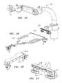
- FIGS. 2-3illustrate exemplary embodiments of operating tables
- FIGS. 4-9illustrate embodiments of a support arm adapter base plate assembly for attaching a support assembly to a operating table
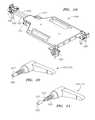
- FIGS. 9A-10illustrate one embodiment of a clamp assembly
- FIG. 11illustrates a perspective view of one embodiment of an adapter plate assembly
- FIG. 12illustrates the adapter plate assembly of FIG. 11 in a first, retracted configuration
- FIG. 13illustrates the adapter plate assembly of FIG. 11 in a second, extended configuration
- FIGS. 14-15illustrate one embodiment of a split clamp and associated rods
- FIG. 16illustrates an enlarged view of the portion of one embodiment of an adapter plate assembly near the surgeon side
- FIGS. 17-18illustrate one embodiment of clamp assemblies
- FIG. 19illustrates another perspective view of one embodiment of the adapter plate assembly
- FIGS. 20-21illustrate different views of one embodiment of an adjustment knob
- FIGS. 22-23illustrate different views of one embodiment of the main plate of the adapter plate assembly
- FIG. 24illustrates yet another view of the adapter plate assembly of one embodiment
- FIG. 25illustrates one embodiment of a support assembly
- FIG. 26illustrates one embodiment of an adapter plate assembly oriented to receive the support assembly of FIG. 25 ;
- FIG. 27illustrates an enlarged view of the support assembly interface for the support assembly of FIG. 25 ;
- FIG. 28illustrates an enlarged view of the adapter plate rail for the adapter plate assembly of FIG. 26 .
- the present inventionis directed to various embodiments of mounting platforms for mounting an instrument driver of a robotic instrument system to an operating table.
- the mounting platform, along with the mounted support assemblycan be used to support and adjust the position of the instrument driver on or near an operating table.
- each of the embodiments described hereinmay be utilized with robotic instrument systems, which can control the positioning of the devices within a patients body, and may also control the operation of other functions of the devices, such as imaging devices, ablation devices, cutting tools, or other end effectors, including without limitation all of the robotic instrument systems incorporated by reference below.
- a robotic instrument system32
- the robotic instrument assembly ( 1002 )comprises an instrument driver ( 16 ) and an instrument ( 18 ) coupled to the operating table ( 22 ) by an instrument driver mounting brace ( 20 ).
- a communication link ( 14 )transfers signals between the operator control station ( 2 ) and instrument driver ( 16 ).
- the instrument driver mounting brace ( 20 ) of the depicted embodimentis a relatively simple, arcuate-shaped structural member configured to position the instrument driver ( 16 ) above a patient (not shown) lying on the table ( 22 ).
- FIG. 1Banother embodiment of a robotic instrument system ( 32 ) is depicted, wherein the arcuate-shaped member ( 20 ) is replaced by a movable support assembly ( 26 ).
- the support assembly ( 26 )is configured to movably support the instrument driver ( 16 ) above the operating table ( 22 ) in order to position the instrument driver ( 16 ) for convenient access into desired locations relative to a patient (not shown).
- the support assembly ( 26 ) in FIG. 1Bis also configured to lock the instrument driver ( 16 ) into position once it is positioned.
- the instrument ( 18 )is typically an elongate, flexible device configured to be inserted into a patient's body.
- an instrument ( 18 )may comprise an intravascular catheter, an endoscopic surgical instrument or other medical instrument.
- the instrument ( 18 )may also comprise an instrument assembly ( 28 ) comprising a robotic guide instrument ( 18 ), or a coaxially coupled and independently controllable robotic sheath instrument and a robotic guide instrument ( 18 ), as described in the U.S. Patent Applications incorporated by reference below.
- the instrument ( 18 ) or instrument assembly ( 28 )is configured to be operable via the instrument driver ( 16 ) such that the instrument driver ( 16 ) can operate to steer the instrument ( 18 ) or instrument assembly ( 28 ) and also to operate tools and devices which may be provided on the instrument assembly ( 18 ) or instrument assembly ( 28 ) (e.g. an imaging device or cutting tool disposed on the distal end of the instrument ( 18 ) or instrument assembly ( 28 )).
- tools and deviceswhich may be provided on the instrument assembly ( 18 ) or instrument assembly ( 28 ) (e.g. an imaging device or cutting tool disposed on the distal end of the instrument ( 18 ) or instrument assembly ( 28 )).
- manually steerable and operable instruments or instrument assembliesmay also be utilized.
- the procedures described hereinmay be utilized with manually or robotically steerable instrument systems, such as those described in the below-referenced U.S. patent application Ser. No. 11/481,433.
- FIG. 1Cprovides a closer view of the support assembly (also referred to as a setup joint) ( 26 ) depicted in the embodiment of FIG. 1B .
- the support assembly ( 26 )comprises a series of rigid links ( 36 ) coupled by electronically braked joints ( 34 ).
- the joints ( 34 )allow motion of the links ( 36 ) when energized by a control system (not shown), but otherwise prevent motion of the links.
- the control systemmay be activated by a switch (e.g., a footswitch or thumbswitch), or computer interface.
- the rigid links ( 36 )may be coupled by mechanically lockable joints, which may be locked and unlocked manually using, for example, locking pins, screws, or clamps.
- the rigid links ( 36 )preferably comprise a light but strong material, such as high-gage aluminum, shaped to withstand the stresses and strains associated with precisely maintaining a three-dimensional position of the approximately ten pound weight of a typical embodiment of the instrument driver ( 16 ) once the position of the link ( 36 ) is fixed.
- An instrument driver support shaft ( 17 )is provided near the distal end of the support assembly ( 26 ), and is coupled to a pivotable instrument driver mounting interface ( 21 ) for attaching the instrument driver ( 16 ).
- the support assembly ( 26 )also has an interface surface ( 1036 ) which may comprise one or more mounting clamps each generally comprising a fixed upper body portion having a mating surface, and upper and lower clamp toe portions configured for detachably coupling to a rail of an operating table ( 22 ).
- FIGS. 2-3an exemplary operating table ( 1003 ) is illustrated.
- the designs and specifications of operating tablesvary widely from manufacturer to manufacturer. Operating tables ( 1003 ) not only differ between manufacturers but also between different models from the same manufacturer. Thus it is desirable to have a uniform mounting platform upon which the support assembly ( 26 ) for the above described robotic instrument system ( 32 ) may be deployed, regardless of the brand of a operating table. Furthermore, it is desirable to have a universal mounting platform that is easily adjustable and adaptable to as many different tablerails as possible. As illustrated in FIG. 1C , one embodiment of a setup joint ( 26 ) is designed to mount directly to a tablerail ( 1004 ).
- tablerails ( 1004 ) of some operating tableshave shown to be weak, thus providing inadequate stiffness to support the weight of the support assembly ( 26 ) and robotic instrument assembly ( 1002 ). This may result in an unstable support assembly.
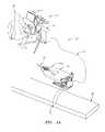
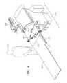
- a support arm adapter base plate assembly ( 1005 )for attaching a support assembly to a operating table ( 1003 ).
- Adapter plate assembly ( 1005 )mounts directly to the operating table ( 1003 ).
- the support assembly ( 26 )is mounted to the adapter plate assembly ( 1005 ).
- the adapter plate assembly ( 1005 )comprises a large, flat main plate ( 1006 ) which lays on top of a operating table ( 1003 ).
- the assembly ( 1005 )is designed with various adjustments to allow it to be mounted to different types of operating table.
- an adapter plate rail ( 1007 )On a first edge of the adapter plate assembly ( 1005 ) is an adapter plate rail ( 1007 ) that is the same or similar to the construction of a traditional operating table rail ( 1004 ). By placing this rail ( 1007 ) on the adapter plate ( 1005 ) itself, a user may be assured that the rail on which a support assembly ( 26 ) will be mounted will have having consistent dimensions.
- the plate rail ( 1007 )may be attached to the main plate ( 1006 ), such as by bolting, welding, or other suitable method, or it may be integral to the main plate ( 1006 ).
- the large, flat surface of the main plate ( 1006 ) of this embodimentprovides stability by distributing the weight of the support assembly ( 26 ) and robotic instrument assembly ( 1002 ) over a relatively large area of the table, whereas a support assembly ( 26 ) mounted directly to the operating table rail ( 1004 ) causes its entire load to be placed on a limited portion of the table rail ( 1004 ).
- a clamp assembly ( 1008 ) and a clamp assembly ( 1009 )are located on opposing sides of the adapter plate assembly ( 1005 ) and are configured to clamp the assembly to the operating table ( 1003 ).
- the clamp assembly ( 1008 )is attached to one side of the main plate ( 1006 ) such that the first clamp assembly ( 1008 ) is located on one side of the operating table when the adapter plate assembly ( 1005 ) is installed; and the clamp assembly ( 1009 ) is attached to the opposing side of the main plate ( 1006 ) such that the clamp assembly ( 1009 ) is located on the other side of the operating table ( 1003 ) when the adapter plate assembly ( 1005 ) is installed.
- a single clamp assembly ( 1008 )is used on the surgeon ( 1010 ) side of the assembly while two assemblies ( 1009 ) are used on the opposite side.
- clamp assemblies ( 1008 and 1009 )may be employed on each side of the plate assembly ( 1005 ).
- a single clamp assembly ( 1008 )is used on the surgeon side of the table ( 1003 ) to minimize the amount of tableside space taken up by the adapter plate assembly ( 1005 ).
- FIG. 9illustrates a operating table ( 1003 ) with adapter plate assembly ( 1005 ) installed from the surgeon ( 1010 ) side of the table ( 1003 ).
- FIGS. 9A and 10one embodiment of a clamp assembly ( 1008 / 1009 ) is illustrated.
- FIG. 9Aillustrates a first perspective view of a clamp assembly ( 1008 ) mounted to a table rail ( 1004 ).
- FIG. 20illustrates another perspective view of a clamp assembly ( 1008 ).
- the clamp assemblies ( 1008 / 1009 ) on both sides of the adapter plate assembly ( 1005 )are identical in design.
- Each clamp assembly ( 1008 / 1009 )comprises an upside down L-shaped metal clamp ( 1011 ) which hooks around the top of the table rail ( 1004 ).
- the clamp assembly ( 1008 )fits on top of the table rail ( 1004 ) and a large knob ( 1012 ) threaded through clamp ( 1011 ) may be adjusted to tighten directly against the table rail ( 1004 ), thus pulling the hook of the clamp ( 1011 ) against the table rail ( 1004 ) and locking the clamp ( 1011 ) in place.
- Another knob ( 1013 )is threaded through the clamp ( 1011 ) directly below the large knob ( 1012 ) but is threaded through at an upward angle. This angled knob ( 1013 ) catches the underside ( 1014 ) of the table rail ( 1004 ).
- the knob ( 1013 )serves as a secondary locking mechanism to the main knob ( 1012 ) and also prevents any twisting due to an unexpected large moment about the operating table.
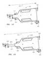
- FIGS. 11-13illustrate a first manner of adjustment of an embodiment of the adapter plate assembly ( 1005 ) which allows the plate assembly ( 1005 ) to be installed on operating tables ( 1003 ) that have different widths.
- FIGS. 11 and 12illustrate another perspective view of one embodiment of the adapter plate assembly ( 1005 ) in a first, retracted configuration.
- FIG. 13illustrates the adapter plate assembly in a second, extended configuration.
- the first adjustable element of the adapter plate assembly ( 1005 )concerns the width ( 1017 ) of the adapter plate assembly ( 1005 ).
- the plate assembly ( 1005 )is adjustable to fit the width ( 1015 ) of the operating table ( 1003 ) (see FIG. 8 ).
- the surgeon side clamp assembly ( 1008 )is mounted on two adjustable rods ( 1019 / 1031 ) that fit in two holes ( 1020 ) that run parallel to the width ( 1017 ) of the adapter main plate ( 1006 ) on one end, and are coupled to a split clamp ( 1022 ) on the other end.
- the rods ( 1019 / 1031 )are held in place by two set knobs ( 1021 ) threaded into the main plate ( 1006 ). By loosening both set knobs ( 1021 ), the rods ( 1019 / 1031 ) are able to slide in and out, thereby essentially increasing and decreasing the effective width of the adapter plate ( 1005 ).
- the set knobs ( 1021 )are tightened and the rods ( 1019 / 1031 ) are locked into place.
- Two adjustable rods ( 1019 and 1031 )are used instead of a single rod to prevent the surgeon side clamp ( 1008 ) from rotating about the rod ( 1019 ) axis. Having two rods also allows for redundancy so that if one rod ( 1019 or 1031 ) breaks or if one knob ( 1021 ) fails, the other remains to preserve the functionality of the system.
- the one or more clamp assemblies ( 1009 )may also be adjustable to adjust the width of the plate assembly ( 1005 ).
- FIGS. 14-15illustrate the split clamp ( 1022 ) and associated rods ( 1019 / 1031 ).
- the adjustable rods ( 1019 / 1031 )are held at their distal ends with a split clamp ( 1022 ).
- the split clamp ( 1022 )is tightened with screws ( 1023 ) that sandwich and tighten the split clamp ( 1022 ) around the rods ( 1019 and 1031 ).
- One of the rods ( 1019 )extends beyond the main split clamp ( 1022 ) to the distal end of the assembly where it couples to the clamp assembly ( 1008 ).
- the adjustable rods ( 1019 / 1031 )are configured such that the adapter plate assembly ( 1005 ) may extend its width ( 1017 ) to about 36 inches, or more. In a case where a table may be wider than 36 inches, the rods ( 1019 / 1031 ) may be replaced with longer length rods.
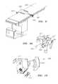
- FIG. 16illustrates an enlarged perspective view of the portion of one embodiment of a plate assembly ( 1005 ) near the surgeon side.
- FIGS. 17-18illustrate an enlarged perspective view o the clamp assembly ( 1008 ) of one embodiment.
- the clamp assemblies ( 1008 / 1009 ) for a single plate assemblyare identical.
- a clamp assemblyis now described.
- Each clamp assembly ( 1008 / 1009 )also allows for a vertical adjustment. Because the distance between the top surface of the table ( 1003 ) and the table rail ( 1004 ) can vary as much as 3-4 inches from table-to-table, a height adjustment on the clamp assembly ( 1005 ) is needed in order to be able to mount the adapter plate clamps ( 1008 / 1009 ) to different types of tables.
- the vertical adjustmentis achieved by providing the clamp component ( 1011 ) with a split clamp ( 1023 ) that can slide up and down on a vertical rod ( 1024 ).
- the split clamp ( 1023 ) in its relaxed statehas an inner diameter that is larger than the outer diameter of the vertical rod ( 1024 ).
- a threaded set knob ( 1025 )passes through a through-hole in one side of the clamp ( 1023 ) and threads into the other side so that when the knob is tightened, the split clamp ( 1023 ) closes, decreasing its inner diameter and locking it onto the vertical rod ( 1024 ).
- the maximum vertical adjustmentis obtained by sliding the clamp assembly ( 1008 / 1009 ) to the bottom of the vertical rod ( 1024 ).
- the vertical rods ( 1024 )could be swapped out for longer rods.
- an alternative embodimentmay include swappable rods.
- the interface between the rod ( 1024 ) and the small split clamp ( 1032 )may be threaded together with a locking nut to lock the rod in place.
- FIG. 19illustrates another perspective view of one embodiment of the plate assembly ( 1005 ).
- FIGS. 20-21illustrate different views of one embodiment of the adjustment knob ( 1021 / 1025 ).
- the set knobs ( 1021 )are used for adjustment of the clamp assemblies ( 1008 and 1009 ) and the set knobs ( 1025 ) are used for adjustment of the adapter plate width adjustment rods ( 1019 / 1031 ).
- the set knobs ( 1021 / 1025 )may be a ratchet type knob for safety wherein the knob does not engage its threads by simply spinning the knob. In order to engage the threads, the knob has to be forced down into the threads along its spinning axis while spinning the knob.
- a locking element ( 1027 )is threaded on the distal end of the adjustment knob ( 1021 and 1025 ).
- the locking element ( 1027 )comprises a groove ( 1028 ) that matches the adjustable rods ( 1019 / 1031 ) and vertical rod ( 1024 ) such that the groove can press up against the respective rod and lock it into place.
- the locking element ( 1027 )is threaded onto the knob ( 1021 / 1025 ) to capture it in the assembly so when the rod ( 1019 / 1031 / 1024 ) is removed from the assembly the locking element ( 1027 ) does not fall out.
- the threads on the distal portion ( 1033 ) of the adjustment knobare reversed from the threads on the proximal end ( 1034 ), i.e. left handed threads to prevent the locking element ( 1027 ) from loosening when the adjustment knob ( 1021 / 1025 ) is tightened into place to lock the adjustment rod ( 1019 / 1031 / 1024 ).
- FIGS. 22-23illustrate different views of one embodiment of the main plate ( 1006 ) of the adapter assembly ( 1005 ).
- the adapter main plate ( 1006 )is shaped like a rectangle that tapers off to create a neck like portion ( 1029 ).
- the main plate ( 1006 )is shaped so that its width dimension in the neck like portion ( 1029 ) is smaller on the surgeon ( 1010 ) side of the table and has a much wider width ( 1018 ) on the opposite side of the table.
- the wide length ( 1018 ) on the opposite side of the tableis intended to increase stability and safety.
- the wide edge ( 1018 )allows for two clamp assemblies ( 1009 ) that can be spaced further apart.
- the plate ( 1006 )increases the overall size of the plate gives the plate ( 1006 ) some size and weight to safely hold the support arm assembly ( 26 ) and instrument driver ( 1002 ) in place even if the clamp assemblies ( 1008 / 1009 ) are mistakenly loosened or insufficiently tightened.
- the smaller width neck ( 1029 ) of the main plate ( 1006 ) in this exampleis intended to reduce the amount of table rail ( 1004 ) space used on the surgeon side of the table ( 1003 ).
- a operating table ( 1003 )may have several pendants mounted to its table rail ( 1004 ) on the surgeon side ( 1010 ) for flouroscopy, display screens, ablation tools, etc.
- the necking ( 1029 ) in one embodiment of a platereduces the need of the table rail ( 1004 ) space to approximately 3 inches. In alternative embodiments, this necking may be reduced or eliminated such that the surgeon side of the plate may be resized to wider dimensions as desired.
- one of the adjustable rods ( 1019 )is extended to hold the clamp assembly ( 1008 ). The rod ( 1019 ) is extended to be able to achieve the minimal three inch tablerail ( 1004 ) space taken by the single clamp assembly ( 1008 ).
- a smaller split clamp ( 1032 )holds the distal end of the fixed rod ( 1019 ) and functions identically to the split clamp ( 1022 ).
- the thickness of the main plate ( 1006 )is chosen to be 3 ⁇ 4′′ inch.
- the thickness of the main plate ( 1006 )can be increased.
- the adjustable rods ( 1019 / 1031 )are pulled out to extend the width of the plate assembly ( 1005 )
- the extended portion ( 1035 ) (see FIG. 24 ) of the assemblydoes not include the thickness of the main plate ( 1006 ).
- a blockcan be placed over the rods to correct for this height discrepancy.
- the main plate ( 1006 )also includes a pair of cut-outs ( 1030 ) which can be used as handles for handling the plate assembly ( 1005 ) and also to reduce the overall weight of the main plate ( 1006 ).
- FIG. 24illustrates yet another view of one embodiment of the adapter plate assembly ( 1005 ).
- the main plate ( 1006 )is aluminum and the adapter plate rail ( 1007 ) is steel.
- other types of materialsmetallic or non-metallic, may be used to construct the various elements of the adapter plate assembly ( 1005 ).
- the adjustment rods ( 1019 / 1031 / 1024 )(both for width and vertical adjustments) of this embodiment may be constructed of steel.
- the split clamps ( 1022 / 1032 ) holding the rod ( 1024 ) and the adjustable rods ( 1019 / 1031 )may also fabricated from steel in this embodiment.
- non-metallic materialssuch as carbon fibers may be used instead of aluminum and steel.
- an assembly with a minimal amount of metalmay be desirable to reduce interference with any imaging modalities that may be used during a surgical procedure.
- FIG. 25illustrates the support assembly ( 26 ) of one embodiment.
- FIG. 26illustrates one embodiment of an adapter plate assembly ( 1005 ) oriented to receive the support assembly ( 26 ) of FIG. 25 .
- FIG. 27illustrates an enlarged view of the support assembly interface surface ( 1036 ) for the support assembly ( 26 ) of FIG. 25 .
- FIG. 28illustrates a close up view of the adapter plate rail ( 1007 ) for the adapter plate assembly ( 1005 ) of FIG. 26 .
- the interface between the adapter plate rail ( 1007 ) and the support assembly interface ( 1036 )may be specifically keyed.
- the support assembly interface ( 1036 )can be angled or keyed to match a mirror image shaped surface on the adapter plate rail ( 1007 ), so that the setup joint ( 26 ) can only be mounted to the adapter plate assembly ( 1005 ).
- Another advantage of this adapter plate platform apparatusis the ability to be able to mount a support assembly ( 26 ) anywhere on the operating table, whether it be surgeon side, far side, center of table, etc.
- this adapter plate assembly ( 1005 )is designed to hold multiple support assemblies ( 26 ) and multiple instrument drivers ( 16 ).
- another rail ( 1007 )may be added to the other side of the table.
- an additional railcould be added to mount a support assembly ( 26 ) that extends from between the patients legs, etc.
- a secondary railcan be added on the same side of the adapter plate assembly ( 1005 ) that extends further from original rail ( 1007 ) such that a pair of support assemblies ( 26 ) may be mounted on the same side of the table; or the rail ( 1007 ) can be lengthened such that it can accommodate two or more support assemblies ( 26 ).
- the adapter plate assembly ( 1005 )may be configured such that the main plate ( 1006 ) is place underneath the operating table ( 1003 ), instead of on top of the operating table ( 1003 ).
Landscapes
- Health & Medical Sciences (AREA)
- Life Sciences & Earth Sciences (AREA)
- Engineering & Computer Science (AREA)
- Surgery (AREA)
- Animal Behavior & Ethology (AREA)
- General Health & Medical Sciences (AREA)
- Veterinary Medicine (AREA)
- Public Health (AREA)
- Biomedical Technology (AREA)
- Molecular Biology (AREA)
- Nuclear Medicine, Radiotherapy & Molecular Imaging (AREA)
- Medical Informatics (AREA)
- Heart & Thoracic Surgery (AREA)
- Robotics (AREA)
- Nursing (AREA)
- Biophysics (AREA)
- Optics & Photonics (AREA)
- Pathology (AREA)
- Radiology & Medical Imaging (AREA)
- Physics & Mathematics (AREA)
- Accommodation For Nursing Or Treatment Tables (AREA)
- Surgical Instruments (AREA)
- Manipulator (AREA)
Abstract
Description
Claims (20)
Priority Applications (1)
| Application Number | Priority Date | Filing Date | Title |
|---|---|---|---|
| US13/910,903US9566201B2 (en) | 2007-02-02 | 2013-06-05 | Mounting support assembly for suspending a medical instrument driver above an operating table |
Applications Claiming Priority (5)
| Application Number | Priority Date | Filing Date | Title |
|---|---|---|---|
| US89904807P | 2007-02-02 | 2007-02-02 | |
| US90058407P | 2007-02-08 | 2007-02-08 | |
| US12/024,883US8146874B2 (en) | 2007-02-02 | 2008-02-01 | Mounting support assembly for suspending a medical instrument driver above an operating table |
| US13/437,716US20120241576A1 (en) | 2007-02-02 | 2012-04-02 | Mounting support assembly for suspending a medical instrument driver above an operating table |
| US13/910,903US9566201B2 (en) | 2007-02-02 | 2013-06-05 | Mounting support assembly for suspending a medical instrument driver above an operating table |
Related Parent Applications (1)
| Application Number | Title | Priority Date | Filing Date |
|---|---|---|---|
| US13/437,716ContinuationUS20120241576A1 (en) | 2007-02-02 | 2012-04-02 | Mounting support assembly for suspending a medical instrument driver above an operating table |
Publications (2)
| Publication Number | Publication Date |
|---|---|
| US20130269109A1 US20130269109A1 (en) | 2013-10-17 |
| US9566201B2true US9566201B2 (en) | 2017-02-14 |
Family
ID=39661452
Family Applications (7)
| Application Number | Title | Priority Date | Filing Date |
|---|---|---|---|
| US12/024,760AbandonedUS20090036900A1 (en) | 2007-02-02 | 2008-02-01 | Surgery methods using a robotic instrument system |
| US12/024,642AbandonedUS20080195081A1 (en) | 2007-02-02 | 2008-02-01 | Spinal surgery methods using a robotic instrument system |
| US12/024,883Expired - Fee RelatedUS8146874B2 (en) | 2007-02-02 | 2008-02-01 | Mounting support assembly for suspending a medical instrument driver above an operating table |
| US12/012,795AbandonedUS20080218770A1 (en) | 2007-02-02 | 2008-02-01 | Robotic surgical instrument and methods using bragg fiber sensors |
| US13/437,716AbandonedUS20120241576A1 (en) | 2007-02-02 | 2012-04-02 | Mounting support assembly for suspending a medical instrument driver above an operating table |
| US13/486,934AbandonedUS20120253332A1 (en) | 2007-02-02 | 2012-06-01 | Surgery methods using a robotic instrument system |
| US13/910,903Active2030-06-05US9566201B2 (en) | 2007-02-02 | 2013-06-05 | Mounting support assembly for suspending a medical instrument driver above an operating table |
Family Applications Before (6)
| Application Number | Title | Priority Date | Filing Date |
|---|---|---|---|
| US12/024,760AbandonedUS20090036900A1 (en) | 2007-02-02 | 2008-02-01 | Surgery methods using a robotic instrument system |
| US12/024,642AbandonedUS20080195081A1 (en) | 2007-02-02 | 2008-02-01 | Spinal surgery methods using a robotic instrument system |
| US12/024,883Expired - Fee RelatedUS8146874B2 (en) | 2007-02-02 | 2008-02-01 | Mounting support assembly for suspending a medical instrument driver above an operating table |
| US12/012,795AbandonedUS20080218770A1 (en) | 2007-02-02 | 2008-02-01 | Robotic surgical instrument and methods using bragg fiber sensors |
| US13/437,716AbandonedUS20120241576A1 (en) | 2007-02-02 | 2012-04-02 | Mounting support assembly for suspending a medical instrument driver above an operating table |
| US13/486,934AbandonedUS20120253332A1 (en) | 2007-02-02 | 2012-06-01 | Surgery methods using a robotic instrument system |
Country Status (2)
| Country | Link |
|---|---|
| US (7) | US20090036900A1 (en) |
| WO (2) | WO2008097540A2 (en) |
Cited By (31)
| Publication number | Priority date | Publication date | Assignee | Title |
|---|---|---|---|---|
| USD792595S1 (en)* | 2016-01-25 | 2017-07-18 | Dongguan Weihong Hardware And Plastic Products Co., Ltd. | Automatic support for headrest |
| USD816848S1 (en)* | 2016-02-22 | 2018-05-01 | Innovative Medical Products, Inc. | Clamp for surgical support table |
| US10159533B2 (en) | 2014-07-01 | 2018-12-25 | Auris Health, Inc. | Surgical system with configurable rail-mounted mechanical arms |
| US10169875B2 (en) | 2015-09-18 | 2019-01-01 | Auris Health, Inc. | Navigation of tubular networks |
| US10219874B2 (en) | 2013-10-24 | 2019-03-05 | Auris Health, Inc. | Instrument device manipulator with tension sensing apparatus |
| US10376672B2 (en) | 2013-03-15 | 2019-08-13 | Auris Health, Inc. | Catheter insertion system and method of fabrication |
| US10398518B2 (en) | 2014-07-01 | 2019-09-03 | Auris Health, Inc. | Articulating flexible endoscopic tool with roll capabilities |
| US10500001B2 (en) | 2015-05-15 | 2019-12-10 | Auris Health, Inc. | Surgical robotics system |
| US10499999B2 (en) | 2014-10-09 | 2019-12-10 | Auris Health, Inc. | Systems and methods for aligning an elongate member with an access site |
| US10543047B2 (en) | 2013-03-15 | 2020-01-28 | Auris Health, Inc. | Remote catheter manipulator |
| US10556092B2 (en) | 2013-03-14 | 2020-02-11 | Auris Health, Inc. | Active drives for robotic catheter manipulators |
| US10631949B2 (en) | 2015-09-09 | 2020-04-28 | Auris Health, Inc. | Instrument device manipulator with back-mounted tool attachment mechanism |
| US10687903B2 (en) | 2013-03-14 | 2020-06-23 | Auris Health, Inc. | Active drive for robotic catheter manipulators |
| US10702348B2 (en) | 2015-04-09 | 2020-07-07 | Auris Health, Inc. | Surgical system with configurable rail-mounted mechanical arms |
| US10792112B2 (en) | 2013-03-15 | 2020-10-06 | Auris Health, Inc. | Active drive mechanism with finite range of motion |
| US10820952B2 (en) | 2013-03-15 | 2020-11-03 | Auris Heath, Inc. | Rotational support for an elongate member |
| US10932691B2 (en) | 2016-01-26 | 2021-03-02 | Auris Health, Inc. | Surgical tools having electromagnetic tracking components |
| US10932861B2 (en) | 2016-01-14 | 2021-03-02 | Auris Health, Inc. | Electromagnetic tracking surgical system and method of controlling the same |
| US11246672B2 (en) | 2019-08-15 | 2022-02-15 | Auris Health, Inc. | Axial motion drive devices, systems, and methods for a robotic medical system |
| US11324554B2 (en) | 2016-04-08 | 2022-05-10 | Auris Health, Inc. | Floating electromagnetic field generator system and method of controlling the same |
| US11419777B1 (en)* | 2021-07-12 | 2022-08-23 | Scott Sledge | Mounting bracket for use with a surgical table |
| US11744670B2 (en) | 2018-01-17 | 2023-09-05 | Auris Health, Inc. | Surgical platform with adjustable arm supports |
| US11844732B2 (en) | 2021-07-30 | 2023-12-19 | Corindus, Inc. | Support for securing a robotic system to a patient table |
| US12232838B2 (en) | 2021-08-12 | 2025-02-25 | Imperative Care, Inc. | Method of robotically performing a neurovascular procedure |
| US12257086B2 (en) | 2022-11-11 | 2025-03-25 | Siemens Healthineers Endovascular Robotics, Inc. | Arrangement for securing a robotic system to a patient table |
| US12295672B2 (en) | 2017-06-23 | 2025-05-13 | Auris Health, Inc. | Robotic systems for determining a roll of a medical device in luminal networks |
| US12329397B2 (en) | 2022-08-02 | 2025-06-17 | Imperative Care, Inc. | Fluidics management system |
| US12377206B2 (en) | 2023-05-17 | 2025-08-05 | Imperative Care, Inc. | Fluidics control system for multi catheter stack |
| US12419703B2 (en) | 2022-08-01 | 2025-09-23 | Imperative Care, Inc. | Robotic drive system for achieving supra-aortic access |
| US12433702B2 (en) | 2022-12-01 | 2025-10-07 | Imperative Care, Inc. | Telescoping drive table |
| US12440289B2 (en) | 2022-12-01 | 2025-10-14 | Imperative Care, Inc. | Method of priming an interventional device assembly |
Families Citing this family (335)
| Publication number | Priority date | Publication date | Assignee | Title |
|---|---|---|---|---|
| WO2005087128A1 (en) | 2004-03-05 | 2005-09-22 | Hansen Medical, Inc. | Robotic catheter system |
| US7781724B2 (en)* | 2004-07-16 | 2010-08-24 | Luna Innovations Incorporated | Fiber optic position and shape sensing device and method relating thereto |
| US20100312129A1 (en) | 2005-01-26 | 2010-12-09 | Schecter Stuart O | Cardiovascular haptic handle system |
| US7789874B2 (en)* | 2005-05-03 | 2010-09-07 | Hansen Medical, Inc. | Support assembly for robotic catheter system |
| JP2009500086A (en) | 2005-07-01 | 2009-01-08 | ハンセン メディカル,インク. | Robotic guide catheter system |
| EP1907041B1 (en)* | 2005-07-11 | 2019-02-20 | Catheter Precision, Inc. | Remotely controlled catheter insertion system |
| US8219178B2 (en) | 2007-02-16 | 2012-07-10 | Catholic Healthcare West | Method and system for performing invasive medical procedures using a surgical robot |
| US10893912B2 (en) | 2006-02-16 | 2021-01-19 | Globus Medical Inc. | Surgical tool systems and methods |
| US10357184B2 (en) | 2012-06-21 | 2019-07-23 | Globus Medical, Inc. | Surgical tool systems and method |
| US10653497B2 (en) | 2006-02-16 | 2020-05-19 | Globus Medical, Inc. | Surgical tool systems and methods |
| US8989528B2 (en) | 2006-02-22 | 2015-03-24 | Hansen Medical, Inc. | Optical fiber grating sensors and methods of manufacture |
| JP5631585B2 (en)* | 2006-03-22 | 2014-11-26 | コーニンクレッカ フィリップス エレクトロニクス エヌ.ヴィ. | Optical fiber equipment sensing system |
| US9232959B2 (en) | 2007-01-02 | 2016-01-12 | Aquabeam, Llc | Multi fluid tissue resection methods and devices |
| US12290277B2 (en) | 2007-01-02 | 2025-05-06 | Aquabeam, Llc | Tissue resection with pressure sensing |
| US20090036900A1 (en) | 2007-02-02 | 2009-02-05 | Hansen Medical, Inc. | Surgery methods using a robotic instrument system |
| WO2008131303A2 (en) | 2007-04-20 | 2008-10-30 | Hansen Medical, Inc. | Optical fiber shape sensing systems |
| US20130165945A9 (en)* | 2007-08-14 | 2013-06-27 | Hansen Medical, Inc. | Methods and devices for controlling a shapeable instrument |
| EP2626030A3 (en) | 2007-08-14 | 2017-03-08 | Koninklijke Philips N.V. | Robotic instrument systems and methods utilizing optical fiber sensors |
| WO2009073577A2 (en)* | 2007-11-29 | 2009-06-11 | Surgiquest, Inc. | Surgical instruments with improved dexterity for use in minimally invasive surgical procedures |
| US9126023B1 (en)* | 2007-12-14 | 2015-09-08 | Gmedelaware 2 Llc | Balloon expandable cement director and related methods |
| WO2009092059A2 (en) | 2008-01-16 | 2009-07-23 | Catheter Robotics, Inc. | Remotely controlled catheter insertion system |
| US9486292B2 (en)* | 2008-02-14 | 2016-11-08 | Immersion Corporation | Systems and methods for real-time winding analysis for knot detection |
| US20090228020A1 (en)* | 2008-03-06 | 2009-09-10 | Hansen Medical, Inc. | In-situ graft fenestration |
| ES2769535T3 (en) | 2008-03-06 | 2020-06-26 | Aquabeam Llc | Tissue ablation and cauterization with optical energy carried in a fluid stream |
| US20090254083A1 (en)* | 2008-03-10 | 2009-10-08 | Hansen Medical, Inc. | Robotic ablation catheter |
| US8792964B2 (en)* | 2008-03-12 | 2014-07-29 | Siemens Aktiengesellschaft | Method and apparatus for conducting an interventional procedure involving heart valves using a robot-based X-ray device |
| EP2240111B1 (en)* | 2008-06-18 | 2019-07-24 | Mako Surgical Corp. | Fiber optic tracking system |
| GB0811971D0 (en) | 2008-06-30 | 2008-07-30 | Oliver Crispin Robotics Ltd | Robotic arm |
| US7815376B2 (en) | 2008-06-30 | 2010-10-19 | Intuitive Surgical Operations, Inc. | Fixture for shape-sensing optical fiber in a kinematic chain |
| US7720322B2 (en) | 2008-06-30 | 2010-05-18 | Intuitive Surgical, Inc. | Fiber optic shape sensor |
| US8290571B2 (en)* | 2008-08-01 | 2012-10-16 | Koninklijke Philips Electronics N.V. | Auxiliary cavity localization |
| KR101903307B1 (en) | 2009-03-26 | 2018-10-01 | 인튜어티브 서지컬 오퍼레이션즈 인코포레이티드 | System for providing visual guidance for steering a tip of an endoscopic device towards one or more landmarks and assisting an operator in endoscopic navigation |
| US8337397B2 (en) | 2009-03-26 | 2012-12-25 | Intuitive Surgical Operations, Inc. | Method and system for providing visual guidance to an operator for steering a tip of an endoscopic device toward one or more landmarks in a patient |
| US10004387B2 (en) | 2009-03-26 | 2018-06-26 | Intuitive Surgical Operations, Inc. | Method and system for assisting an operator in endoscopic navigation |
| US9254123B2 (en) | 2009-04-29 | 2016-02-09 | Hansen Medical, Inc. | Flexible and steerable elongate instruments with shape control and support elements |
| SG176213A1 (en)* | 2009-05-29 | 2011-12-29 | Univ Nanyang Tech | Robotic system for flexible endoscopy |
| US8780339B2 (en) | 2009-07-15 | 2014-07-15 | Koninklijke Philips N.V. | Fiber shape sensing systems and methods |
| JP2012533383A (en)* | 2009-07-20 | 2012-12-27 | ザ エーデルマン リサーチ リミテッド | Surgical access device |
| US8377013B2 (en)* | 2009-08-05 | 2013-02-19 | The University Of Toledo | Needle for directional control of the injection of bone cement into a vertebral compression fracture |
| KR101680132B1 (en)* | 2009-10-01 | 2016-11-28 | 마코 서지컬 코포레이션 | Tool, kit-of-parts for multi-functional tool, and robotic system for same |
| US10045882B2 (en) | 2009-10-30 | 2018-08-14 | The Johns Hopkins University | Surgical instrument and systems with integrated optical sensor |
| CN102711586B (en) | 2010-02-11 | 2015-06-17 | 直观外科手术操作公司 | Method and system for automatically maintaining an operator selected roll orientation at a distal tip of a robotic endoscope |
| US9285246B2 (en)* | 2010-02-12 | 2016-03-15 | Intuitive Surgical Operations, Inc. | Method and system for absolute three-dimensional measurements using a twist-insensitive shape sensor |
| US9220554B2 (en) | 2010-02-18 | 2015-12-29 | Globus Medical, Inc. | Methods and apparatus for treating vertebral fractures |
| NO330598B1 (en)* | 2010-03-10 | 2011-05-23 | Seabed Rig As | Method and apparatus for ensuring the operation of automatic or autonomous equipment |
| US8672837B2 (en) | 2010-06-24 | 2014-03-18 | Hansen Medical, Inc. | Methods and devices for controlling a shapeable medical device |
| US8460236B2 (en) | 2010-06-24 | 2013-06-11 | Hansen Medical, Inc. | Fiber optic instrument sensing system |
| AU2011302155B2 (en)* | 2010-09-14 | 2015-07-02 | The Johns Hopkins University | Robotic system to augment endoscopes |
| US20120071752A1 (en) | 2010-09-17 | 2012-03-22 | Sewell Christopher M | User interface and method for operating a robotic medical system |
| JP5944395B2 (en) | 2010-10-08 | 2016-07-05 | コーニンクレッカ フィリップス エヌ ヴェKoninklijke Philips N.V. | Flexible tether with integrated sensor for dynamic instrument tracking |
| WO2012059867A1 (en)* | 2010-11-05 | 2012-05-10 | Koninklijke Philips Electronics N.V. | Imaging apparatus for imaging an object |
| US20120190970A1 (en) | 2010-11-10 | 2012-07-26 | Gnanasekar Velusamy | Apparatus and method for stabilizing a needle |
| US9486189B2 (en) | 2010-12-02 | 2016-11-08 | Hitachi Aloka Medical, Ltd. | Assembly for use with surgery system |
| US20120191079A1 (en) | 2011-01-20 | 2012-07-26 | Hansen Medical, Inc. | System and method for endoluminal and translumenal therapy |
| WO2012101563A2 (en)* | 2011-01-27 | 2012-08-02 | Koninklijke Philips Electronics N.V. | Integration of fiber optic shape sensing within an nterventional environment |
| EP2491883B1 (en)* | 2011-02-24 | 2014-06-18 | VascoMed GmbH | Catheter and catheter arrangement |
| US9308050B2 (en)* | 2011-04-01 | 2016-04-12 | Ecole Polytechnique Federale De Lausanne (Epfl) | Robotic system and method for spinal and other surgeries |
| WO2012131658A1 (en)* | 2011-04-01 | 2012-10-04 | Ecole Polytechnique Federale De Lausanne (Epfl) | Small active medical robot and passive holding structure |
| US8942828B1 (en) | 2011-04-13 | 2015-01-27 | Stuart Schecter, LLC | Minimally invasive cardiovascular support system with true haptic coupling |
| KR101782352B1 (en) | 2011-04-25 | 2017-09-29 | 한국기술교육대학교 산학협력단 | Apparatus For Measuring Operating Cable Force which applied to the Robot Manipulator Using Fiber Bragg Grating Sensor And Romote Operating Apparatus for Robot Mnipulator thereof |
| US9572481B2 (en)* | 2011-05-13 | 2017-02-21 | Intuitive Surgical Operations, Inc. | Medical system with multiple operating modes for steering a medical instrument through linked body passages |
| US8900131B2 (en) | 2011-05-13 | 2014-12-02 | Intuitive Surgical Operations, Inc. | Medical system providing dynamic registration of a model of an anatomical structure for image-guided surgery |
| US9393001B2 (en)* | 2011-07-29 | 2016-07-19 | Olympus Corporation | Operation method of endoscope |
| US20130030363A1 (en) | 2011-07-29 | 2013-01-31 | Hansen Medical, Inc. | Systems and methods utilizing shape sensing fibers |
| US9259155B2 (en) | 2011-08-16 | 2016-02-16 | Koninklijke Philips N.V. | Method to estimate interfractional and intrafractional organ motion for adaptive external beam radiotherapy |
| ITFI20110186A1 (en)* | 2011-08-26 | 2013-02-27 | Scuola Superiore Di Studi Universit Arie Di Perfe | ROBOTIC DEVICE FOR NEURAL INTERFACE PLANT IN THE PERIPHERAL NERVOUS SYSTEM |
| IN2014CN02655A (en) | 2011-10-20 | 2015-06-26 | Koninkl Philips Nv | |
| US9622779B2 (en) | 2011-10-27 | 2017-04-18 | DePuy Synthes Products, Inc. | Method and devices for a sub-splenius / supra-levator scapulae surgical access technique |
| US9622825B2 (en)* | 2011-11-28 | 2017-04-18 | National University Of Singapore | Robotic system for flexible endoscopy |
| US8652031B2 (en) | 2011-12-29 | 2014-02-18 | St. Jude Medical, Atrial Fibrillation Division, Inc. | Remote guidance system for medical devices for use in environments having electromagnetic interference |
| US9956042B2 (en) | 2012-01-13 | 2018-05-01 | Vanderbilt University | Systems and methods for robot-assisted transurethral exploration and intervention |
| JP6290099B2 (en)* | 2012-02-03 | 2018-03-07 | インテュイティブ サージカル オペレーションズ, インコーポレイテッド | Steerable flexible needle with implantable shape sensing function |
| EP3351196A1 (en) | 2012-02-29 | 2018-07-25 | Procept Biorobotics Corporation | Automated image-guided tissue resection and treatment |
| US9687303B2 (en) | 2012-04-20 | 2017-06-27 | Vanderbilt University | Dexterous wrists for surgical intervention |
| US9539726B2 (en)* | 2012-04-20 | 2017-01-10 | Vanderbilt University | Systems and methods for safe compliant insertion and hybrid force/motion telemanipulation of continuum robots |
| WO2013158983A1 (en) | 2012-04-20 | 2013-10-24 | Vanderbilt University | Robotic device for establishing access channel |
| US20130317519A1 (en) | 2012-05-25 | 2013-11-28 | Hansen Medical, Inc. | Low friction instrument driver interface for robotic systems |
| US10013082B2 (en) | 2012-06-05 | 2018-07-03 | Stuart Schecter, LLC | Operating system with haptic interface for minimally invasive, hand-held surgical instrument |
| CN108420598B (en) | 2012-06-12 | 2021-03-09 | 爱尔康公司 | Hand-held gas mixer and injector assembly, hand-held gas injector device and method of mixing gas |
| US12004905B2 (en) | 2012-06-21 | 2024-06-11 | Globus Medical, Inc. | Medical imaging systems using robotic actuators and related methods |
| US11793570B2 (en) | 2012-06-21 | 2023-10-24 | Globus Medical Inc. | Surgical robotic automation with tracking markers |
| US11253327B2 (en) | 2012-06-21 | 2022-02-22 | Globus Medical, Inc. | Systems and methods for automatically changing an end-effector on a surgical robot |
| US11864839B2 (en) | 2012-06-21 | 2024-01-09 | Globus Medical Inc. | Methods of adjusting a virtual implant and related surgical navigation systems |
| US11395706B2 (en) | 2012-06-21 | 2022-07-26 | Globus Medical Inc. | Surgical robot platform |
| US11864745B2 (en) | 2012-06-21 | 2024-01-09 | Globus Medical, Inc. | Surgical robotic system with retractor |
| US11399900B2 (en) | 2012-06-21 | 2022-08-02 | Globus Medical, Inc. | Robotic systems providing co-registration using natural fiducials and related methods |
| US11857266B2 (en) | 2012-06-21 | 2024-01-02 | Globus Medical, Inc. | System for a surveillance marker in robotic-assisted surgery |
| US11298196B2 (en) | 2012-06-21 | 2022-04-12 | Globus Medical Inc. | Surgical robotic automation with tracking markers and controlled tool advancement |
| US11116576B2 (en) | 2012-06-21 | 2021-09-14 | Globus Medical Inc. | Dynamic reference arrays and methods of use |
| EP2863827B1 (en) | 2012-06-21 | 2022-11-16 | Globus Medical, Inc. | Surgical robot platform |
| US11045267B2 (en) | 2012-06-21 | 2021-06-29 | Globus Medical, Inc. | Surgical robotic automation with tracking markers |
| US10758315B2 (en) | 2012-06-21 | 2020-09-01 | Globus Medical Inc. | Method and system for improving 2D-3D registration convergence |
| US12220120B2 (en) | 2012-06-21 | 2025-02-11 | Globus Medical, Inc. | Surgical robotic system with retractor |
| US11857149B2 (en) | 2012-06-21 | 2024-01-02 | Globus Medical, Inc. | Surgical robotic systems with target trajectory deviation monitoring and related methods |
| US11974822B2 (en) | 2012-06-21 | 2024-05-07 | Globus Medical Inc. | Method for a surveillance marker in robotic-assisted surgery |
| US11317971B2 (en) | 2012-06-21 | 2022-05-03 | Globus Medical, Inc. | Systems and methods related to robotic guidance in surgery |
| US12262954B2 (en) | 2012-06-21 | 2025-04-01 | Globus Medical, Inc. | Surgical robotic automation with tracking markers |
| US10136954B2 (en) | 2012-06-21 | 2018-11-27 | Globus Medical, Inc. | Surgical tool systems and method |
| US12310683B2 (en) | 2012-06-21 | 2025-05-27 | Globus Medical, Inc. | Surgical tool systems and method |
| US20150032164A1 (en) | 2012-06-21 | 2015-01-29 | Globus Medical, Inc. | Methods for Performing Invasive Medical Procedures Using a Surgical Robot |
| US10350013B2 (en) | 2012-06-21 | 2019-07-16 | Globus Medical, Inc. | Surgical tool systems and methods |
| US11607149B2 (en) | 2012-06-21 | 2023-03-21 | Globus Medical Inc. | Surgical tool systems and method |
| US10624710B2 (en) | 2012-06-21 | 2020-04-21 | Globus Medical, Inc. | System and method for measuring depth of instrumentation |
| US12329593B2 (en) | 2012-06-21 | 2025-06-17 | Globus Medical, Inc. | Surgical robotic automation with tracking markers |
| US10231791B2 (en) | 2012-06-21 | 2019-03-19 | Globus Medical, Inc. | Infrared signal based position recognition system for use with a robot-assisted surgery |
| RU2515850C1 (en)* | 2012-10-04 | 2014-05-20 | государственное бюджетное образовательное учреждение высшего профессионального образования "Омская государственная медицинская академия" Министерства здравоохранения Российской Федерации (ГБОУ ВПО ОмГМА Минздрава России) | Method for combined drainage of pleural cavity and intermuscular spaces accompanying spinal operations in children |
| CN104736085B (en) | 2012-10-12 | 2018-01-30 | 直观外科手术操作公司 | Determining the location of medical devices in branching anatomy |
| DE102012110193B4 (en) | 2012-10-25 | 2023-03-30 | Abb Schweiz Ag | Holding device for the detachable attachment of a robot |
| US10231867B2 (en) | 2013-01-18 | 2019-03-19 | Auris Health, Inc. | Method, apparatus and system for a water jet |
| US9533121B2 (en) | 2013-02-26 | 2017-01-03 | Catheter Precision, Inc. | Components and methods for accommodating guidewire catheters on a catheter controller system |
| US9532840B2 (en) | 2013-03-08 | 2017-01-03 | Hansen Medical, Inc. | Slider control of catheters and wires |
| US10149720B2 (en) | 2013-03-08 | 2018-12-11 | Auris Health, Inc. | Method, apparatus, and a system for facilitating bending of an instrument in a surgical or medical robotic environment |
| US10080576B2 (en) | 2013-03-08 | 2018-09-25 | Auris Health, Inc. | Method, apparatus, and a system for facilitating bending of an instrument in a surgical or medical robotic environment |
| US9057600B2 (en) | 2013-03-13 | 2015-06-16 | Hansen Medical, Inc. | Reducing incremental measurement sensor error |
| US9629595B2 (en) | 2013-03-15 | 2017-04-25 | Hansen Medical, Inc. | Systems and methods for localizing, tracking and/or controlling medical instruments |
| US9014851B2 (en) | 2013-03-15 | 2015-04-21 | Hansen Medical, Inc. | Systems and methods for tracking robotically controlled medical instruments |
| US9271663B2 (en) | 2013-03-15 | 2016-03-01 | Hansen Medical, Inc. | Flexible instrument localization from both remote and elongation sensors |
| US11020016B2 (en) | 2013-05-30 | 2021-06-01 | Auris Health, Inc. | System and method for displaying anatomy and devices on a movable display |
| WO2014201165A1 (en) | 2013-06-11 | 2014-12-18 | Auris Surgical Robotics, Inc. | System for robotic assisted cataract surgery |
| JP2015016181A (en)* | 2013-07-12 | 2015-01-29 | オリンパス株式会社 | Surgery support robot |
| US10426661B2 (en) | 2013-08-13 | 2019-10-01 | Auris Health, Inc. | Method and apparatus for laser assisted cataract surgery |
| US9724493B2 (en) | 2013-08-27 | 2017-08-08 | Catheter Precision, Inc. | Components and methods for balancing a catheter controller system with a counterweight |
| US9993614B2 (en) | 2013-08-27 | 2018-06-12 | Catheter Precision, Inc. | Components for multiple axis control of a catheter in a catheter positioning system |
| JP6482561B2 (en) | 2013-09-04 | 2019-03-13 | コーニンクレッカ フィリップス エヌ ヴェKoninklijke Philips N.V. | Robot system |
| US9750577B2 (en) | 2013-09-06 | 2017-09-05 | Catheter Precision, Inc. | Single hand operated remote controller for remote catheter positioning system |
| US9999751B2 (en) | 2013-09-06 | 2018-06-19 | Catheter Precision, Inc. | Adjustable nose cone for a catheter positioning system |
| US9700698B2 (en) | 2013-09-27 | 2017-07-11 | Catheter Precision, Inc. | Components and methods for a catheter positioning system with a spreader and track |
| US9795764B2 (en) | 2013-09-27 | 2017-10-24 | Catheter Precision, Inc. | Remote catheter positioning system with hoop drive assembly |
| US9283048B2 (en) | 2013-10-04 | 2016-03-15 | KB Medical SA | Apparatus and systems for precise guidance of surgical tools |
| WO2015077584A2 (en) | 2013-11-22 | 2015-05-28 | Massachusetts Institute Of Technology | Steering techniques for surgical instruments |
| US20150148838A1 (en)* | 2013-11-26 | 2015-05-28 | Novartis Ag | Systems and Methods for a Surgical Tissue Manipulator |
| WO2015092581A1 (en)* | 2013-12-17 | 2015-06-25 | Koninklijke Philips N.V. | Shape sensed robotic ultrasound for minimally invasive interventions |
| US9241771B2 (en) | 2014-01-15 | 2016-01-26 | KB Medical SA | Notched apparatus for guidance of an insertable instrument along an axis during spinal surgery |
| WO2015121311A1 (en) | 2014-02-11 | 2015-08-20 | KB Medical SA | Sterile handle for controlling a robotic surgical system from a sterile field |
| KR102237597B1 (en)* | 2014-02-18 | 2021-04-07 | 삼성전자주식회사 | Master device for surgical robot and control method thereof |
| DE102014203921B4 (en)* | 2014-03-04 | 2017-11-09 | Deutsches Zentrum für Luft- und Raumfahrt e.V. | management systems |
| WO2015138317A1 (en) | 2014-03-10 | 2015-09-17 | Stryker Corporation | Limb positioning system |
| US9907696B2 (en)* | 2014-04-18 | 2018-03-06 | The Johns Hopkins University | Fiber optic distal sensor controlled micro-manipulation systems and methods |
| EP3134022B1 (en) | 2014-04-24 | 2018-01-10 | KB Medical SA | Surgical instrument holder for use with a robotic surgical system |
| CN106999248B (en) | 2014-06-19 | 2021-04-06 | Kb医疗公司 | Systems and methods for performing minimally invasive surgery |
| US9744335B2 (en) | 2014-07-01 | 2017-08-29 | Auris Surgical Robotics, Inc. | Apparatuses and methods for monitoring tendons of steerable catheters |
| US10792464B2 (en) | 2014-07-01 | 2020-10-06 | Auris Health, Inc. | Tool and method for using surgical endoscope with spiral lumens |
| US10357257B2 (en) | 2014-07-14 | 2019-07-23 | KB Medical SA | Anti-skid surgical instrument for use in preparing holes in bone tissue |
| US20170304021A1 (en)* | 2014-09-23 | 2017-10-26 | Covidien Lp | Surgical robotic arm support systems and methods of use |
| EP3200718A4 (en) | 2014-09-30 | 2018-04-25 | Auris Surgical Robotics, Inc | Configurable robotic surgical system with virtual rail and flexible endoscope |
| WO2016076964A2 (en)* | 2014-09-30 | 2016-05-19 | Massachusetts Institute Of Technology | Instruments for minimally invasive surgical procedures |
| US20160097658A1 (en)* | 2014-10-06 | 2016-04-07 | Caterpillar Inc. | Fiber optic implement position determination system |
| KR102477470B1 (en) | 2014-11-21 | 2022-12-13 | 씽크 써지컬, 인크. | Visible light communication system for transmitting data between visual tracking systems and tracking markers |
| EP3226781B1 (en) | 2014-12-02 | 2018-08-01 | KB Medical SA | Robot assisted volume removal during surgery |
| WO2016114981A1 (en)* | 2015-01-12 | 2016-07-21 | Intuitive Surgical Operations, Inc. | Devices, systems, and methods for anchoring actuation wires to a steerable instrument |
| US10013808B2 (en) | 2015-02-03 | 2018-07-03 | Globus Medical, Inc. | Surgeon head-mounted display apparatuses |
| WO2016131903A1 (en) | 2015-02-18 | 2016-08-25 | KB Medical SA | Systems and methods for performing minimally invasive spinal surgery with a robotic surgical system using a percutaneous technique |
| KR20230162122A (en) | 2015-02-20 | 2023-11-28 | 스트리커 코포레이션 | Sterile barrier assembly, mounting system, and method for coupling surgical components |
| US9951904B2 (en) | 2015-03-24 | 2018-04-24 | Stryker Corporation | Rotatable seat clamps for rail clamp |
| US11819636B2 (en) | 2015-03-30 | 2023-11-21 | Auris Health, Inc. | Endoscope pull wire electrical circuit |
| US20160287279A1 (en) | 2015-04-01 | 2016-10-06 | Auris Surgical Robotics, Inc. | Microsurgical tool for robotic applications |
| USD787071S1 (en)* | 2015-06-25 | 2017-05-16 | General Electric Company | Integration management system for patient table |
| US10646298B2 (en) | 2015-07-31 | 2020-05-12 | Globus Medical, Inc. | Robot arm and methods of use |
| US10058394B2 (en) | 2015-07-31 | 2018-08-28 | Globus Medical, Inc. | Robot arm and methods of use |
| US10080615B2 (en) | 2015-08-12 | 2018-09-25 | Globus Medical, Inc. | Devices and methods for temporary mounting of parts to bone |
| JP6894431B2 (en) | 2015-08-31 | 2021-06-30 | ケービー メディカル エスアー | Robotic surgical system and method |
| US10034716B2 (en) | 2015-09-14 | 2018-07-31 | Globus Medical, Inc. | Surgical robotic systems and methods thereof |
| US9771092B2 (en) | 2015-10-13 | 2017-09-26 | Globus Medical, Inc. | Stabilizer wheel assembly and methods of use |
| US10231793B2 (en) | 2015-10-30 | 2019-03-19 | Auris Health, Inc. | Object removal through a percutaneous suction tube |
| US9955986B2 (en) | 2015-10-30 | 2018-05-01 | Auris Surgical Robotics, Inc. | Basket apparatus |
| US9949749B2 (en) | 2015-10-30 | 2018-04-24 | Auris Surgical Robotics, Inc. | Object capture with a basket |
| US10143526B2 (en) | 2015-11-30 | 2018-12-04 | Auris Health, Inc. | Robot-assisted driving systems and methods |
| CN106859780B (en)* | 2015-12-11 | 2020-01-10 | 四川锦江电子科技有限公司 | Switching equipment fixing device |
| US10117632B2 (en) | 2016-02-03 | 2018-11-06 | Globus Medical, Inc. | Portable medical imaging system with beam scanning collimator |
| US11883217B2 (en) | 2016-02-03 | 2024-01-30 | Globus Medical, Inc. | Portable medical imaging system and method |
| US11058378B2 (en) | 2016-02-03 | 2021-07-13 | Globus Medical, Inc. | Portable medical imaging system |
| US10448910B2 (en) | 2016-02-03 | 2019-10-22 | Globus Medical, Inc. | Portable medical imaging system |
| US10842453B2 (en) | 2016-02-03 | 2020-11-24 | Globus Medical, Inc. | Portable medical imaging system |
| US10866119B2 (en) | 2016-03-14 | 2020-12-15 | Globus Medical, Inc. | Metal detector for detecting insertion of a surgical device into a hollow tube |
| EP3241518B1 (en) | 2016-04-11 | 2024-10-23 | Globus Medical, Inc | Surgical tool systems |
| US10743891B2 (en) | 2016-07-13 | 2020-08-18 | Washington University | Discectomy instrument |
| US10463439B2 (en) | 2016-08-26 | 2019-11-05 | Auris Health, Inc. | Steerable catheter with shaft load distributions |
| US11389360B2 (en)* | 2016-09-16 | 2022-07-19 | Verb Surgical Inc. | Linkage mechanisms for mounting robotic arms to a surgical table |
| WO2018053281A1 (en)* | 2016-09-16 | 2018-03-22 | Verb Surgical Inc. | Table adapters for mounting robotic arms to a surgical table |
| EP3512450A4 (en)* | 2016-09-16 | 2020-11-04 | Mobius Imaging LLC | System and method for mounting a robotic arm in a surgical robotic system |
| JP6987851B2 (en)* | 2016-09-19 | 2022-01-05 | インテュイティブ サージカル オペレーションズ, インコーポレイテッド | Positioning indicator system for remotely controllable arms and related methods |
| JP7167035B2 (en)* | 2016-09-21 | 2022-11-08 | インテュイティブ サージカル オペレーションズ, インコーポレイテッド | Systems and methods for instrument buckling detection |
| EP3576596A4 (en) | 2016-12-02 | 2021-01-06 | Vanderbilt University | STEERABLE ENDOSCOPE WITH CONTINUOUS MANIPULATOR |
| US10244926B2 (en) | 2016-12-28 | 2019-04-02 | Auris Health, Inc. | Detecting endolumenal buckling of flexible instruments |
| JP7233841B2 (en)* | 2017-01-18 | 2023-03-07 | ケービー メディカル エスアー | Robotic Navigation for Robotic Surgical Systems |
| US11071594B2 (en) | 2017-03-16 | 2021-07-27 | KB Medical SA | Robotic navigation of robotic surgical systems |
| CN108934160B (en) | 2017-03-28 | 2021-08-31 | 奥瑞斯健康公司 | Shaft actuating handle |
| WO2018183727A1 (en) | 2017-03-31 | 2018-10-04 | Auris Health, Inc. | Robotic systems for navigation of luminal networks that compensate for physiological noise |
| US10285574B2 (en) | 2017-04-07 | 2019-05-14 | Auris Health, Inc. | Superelastic medical instrument |
| EP3606400B1 (en) | 2017-04-07 | 2022-03-09 | Auris Health, Inc. | Patient introducer alignment |
| US10349986B2 (en) | 2017-04-20 | 2019-07-16 | Warsaw Orthopedic, Inc. | Spinal implant system and method |
| KR102576296B1 (en) | 2017-05-17 | 2023-09-08 | 아우리스 헬스, 인코포레이티드 | Interchangeable working channels |
| CN116725667A (en) | 2017-06-28 | 2023-09-12 | 奥瑞斯健康公司 | System for providing positioning information and method for positioning an instrument within an anatomical structure |
| WO2019005696A1 (en) | 2017-06-28 | 2019-01-03 | Auris Health, Inc. | Electromagnetic distortion detection |
| US11135015B2 (en) | 2017-07-21 | 2021-10-05 | Globus Medical, Inc. | Robot surgical platform |
| US10967504B2 (en) | 2017-09-13 | 2021-04-06 | Vanderbilt University | Continuum robots with multi-scale motion through equilibrium modulation |
| US11096754B2 (en) | 2017-10-04 | 2021-08-24 | Mako Surgical Corp. | Sterile drape assembly for surgical robot |
| US11058493B2 (en) | 2017-10-13 | 2021-07-13 | Auris Health, Inc. | Robotic system configured for navigation path tracing |
| US10555778B2 (en) | 2017-10-13 | 2020-02-11 | Auris Health, Inc. | Image-based branch detection and mapping for navigation |
| EP3492032B1 (en) | 2017-11-09 | 2023-01-04 | Globus Medical, Inc. | Surgical robotic systems for bending surgical rods |
| US11794338B2 (en) | 2017-11-09 | 2023-10-24 | Globus Medical Inc. | Robotic rod benders and related mechanical and motor housings |
| US11357548B2 (en) | 2017-11-09 | 2022-06-14 | Globus Medical, Inc. | Robotic rod benders and related mechanical and motor housings |
| US11134862B2 (en) | 2017-11-10 | 2021-10-05 | Globus Medical, Inc. | Methods of selecting surgical implants and related devices |
| US11510736B2 (en) | 2017-12-14 | 2022-11-29 | Auris Health, Inc. | System and method for estimating instrument location |
| WO2019125964A1 (en) | 2017-12-18 | 2019-06-27 | Auris Health, Inc. | Methods and systems for instrument tracking and navigation within luminal networks |
| TR201722919A2 (en)* | 2017-12-29 | 2019-07-22 | Erhan Ilhan Konukseven | POSITIONING SYSTEM IN SURGICAL BRANCHES WITH FIBER BRAGG GRILL-BASED OPTICAL SENSORS |
| US20190254753A1 (en) | 2018-02-19 | 2019-08-22 | Globus Medical, Inc. | Augmented reality navigation systems for use with robotic surgical systems and methods of their use |
| JP7225259B2 (en) | 2018-03-28 | 2023-02-20 | オーリス ヘルス インコーポレイテッド | Systems and methods for indicating probable location of instruments |
| WO2019191144A1 (en) | 2018-03-28 | 2019-10-03 | Auris Health, Inc. | Systems and methods for registration of location sensors |
| CN117017505A (en) | 2018-03-28 | 2023-11-10 | 奥瑞斯健康公司 | Composite instrument and robotic system |
| US10573023B2 (en) | 2018-04-09 | 2020-02-25 | Globus Medical, Inc. | Predictive visualization of medical imaging scanner component movement |
| US20190307511A1 (en) | 2018-04-10 | 2019-10-10 | Biosense Webster (Israel) Ltd. | Catheter localization using fiber optic shape sensing combined with current location |
| WO2019211150A1 (en)* | 2018-05-02 | 2019-11-07 | Koninklijke Philips N.V. | Intraluminal medical imaging interface devices and systems |
| US12004912B2 (en) | 2018-05-10 | 2024-06-11 | Intuitive Surgical Operations, Inc. | Mounting teleoperated surgical arms |
| US11013574B1 (en)* | 2018-05-10 | 2021-05-25 | Intuitive Surgical Operations, Inc. | Mounting teleoperated surgical arms |
| US10905499B2 (en) | 2018-05-30 | 2021-02-02 | Auris Health, Inc. | Systems and methods for location sensor-based branch prediction |
| MX2020012904A (en) | 2018-05-31 | 2021-02-26 | Auris Health Inc | Image-based airway analysis and mapping. |
| KR102567087B1 (en) | 2018-05-31 | 2023-08-17 | 아우리스 헬스, 인코포레이티드 | Robotic systems and methods for navigation of luminal networks detecting physiological noise |
| JP7371026B2 (en) | 2018-05-31 | 2023-10-30 | オーリス ヘルス インコーポレイテッド | Path-based navigation of tubular networks |
| JP7267309B2 (en) | 2018-06-07 | 2023-05-01 | オーリス ヘルス インコーポレイテッド | Robotic medical system with high-strength instruments |
| JP7391886B2 (en) | 2018-06-28 | 2023-12-05 | オーリス ヘルス インコーポレイテッド | Medical system incorporating pulley sharing |
| WO2020033318A1 (en) | 2018-08-07 | 2020-02-13 | Auris Health, Inc. | Combining strain-based shape sensing with catheter control |
| WO2020036685A1 (en) | 2018-08-15 | 2020-02-20 | Auris Health, Inc. | Medical instruments for tissue cauterization |
| WO2020036686A1 (en) | 2018-08-17 | 2020-02-20 | Auris Health, Inc. | Bipolar medical instrument |
| US11648058B2 (en) | 2018-09-24 | 2023-05-16 | Simplify Medical Pty Ltd | Robotic system and method for bone preparation for intervertebral disc prosthesis implantation |
| US11819424B2 (en) | 2018-09-24 | 2023-11-21 | Simplify Medical Pty Ltd | Robot assisted intervertebral disc prosthesis selection and implantation system |
| US11160672B2 (en) | 2018-09-24 | 2021-11-02 | Simplify Medical Pty Ltd | Robotic systems and methods for distraction in intervertebral disc prosthesis implantation |
| CN112770689B (en) | 2018-09-26 | 2024-07-19 | 奥瑞斯健康公司 | Systems and instruments for suction and irrigation |
| CN112804933B (en) | 2018-09-26 | 2024-10-18 | 奥瑞斯健康公司 | Articulating medical device |
| CN112804959B (en) | 2018-09-28 | 2025-01-28 | 奥瑞斯健康公司 | Robotic systems and methods for accompanying endoscopic and percutaneous medical procedures |
| US11576738B2 (en) | 2018-10-08 | 2023-02-14 | Auris Health, Inc. | Systems and instruments for tissue sealing |
| US11446055B1 (en) | 2018-10-18 | 2022-09-20 | Lumoptik, Inc. | Light assisted needle placement system and method |
| US11224537B2 (en) | 2018-10-19 | 2022-01-18 | Alcon Inc. | Intraocular gas injector |
| US11337742B2 (en) | 2018-11-05 | 2022-05-24 | Globus Medical Inc | Compliant orthopedic driver |
| US11278360B2 (en) | 2018-11-16 | 2022-03-22 | Globus Medical, Inc. | End-effectors for surgical robotic systems having sealed optical components |
| US11602402B2 (en) | 2018-12-04 | 2023-03-14 | Globus Medical, Inc. | Drill guide fixtures, cranial insertion fixtures, and related methods and robotic systems |
| US11744655B2 (en) | 2018-12-04 | 2023-09-05 | Globus Medical, Inc. | Drill guide fixtures, cranial insertion fixtures, and related methods and robotic systems |
| AU2019391083B2 (en) | 2018-12-04 | 2025-07-24 | Mako Surgical Corp. | Mounting system with sterile barrier assembly for use in coupling surgical components |
| WO2020131529A1 (en) | 2018-12-20 | 2020-06-25 | Auris Health, Inc. | Shielding for wristed instruments |
| WO2020139973A1 (en) | 2018-12-28 | 2020-07-02 | Auris Health, Inc. | Medical instrument with articulable segment |
| EP3883492B1 (en) | 2019-01-25 | 2025-05-21 | Auris Health, Inc. | Vessel sealer with heating capabilities |
| DE102019102075B4 (en)* | 2019-01-28 | 2022-08-18 | Avateramedical Digital Solutions Gmbh | Actuated kinematics for mounting in a vertical position |
| US11918313B2 (en) | 2019-03-15 | 2024-03-05 | Globus Medical Inc. | Active end effectors for surgical robots |
| US20200297357A1 (en) | 2019-03-22 | 2020-09-24 | Globus Medical, Inc. | System for neuronavigation registration and robotic trajectory guidance, robotic surgery, and related methods and devices |
| US11571265B2 (en) | 2019-03-22 | 2023-02-07 | Globus Medical Inc. | System for neuronavigation registration and robotic trajectory guidance, robotic surgery, and related methods and devices |
| US11806084B2 (en) | 2019-03-22 | 2023-11-07 | Globus Medical, Inc. | System for neuronavigation registration and robotic trajectory guidance, and related methods and devices |
| US11382549B2 (en) | 2019-03-22 | 2022-07-12 | Globus Medical, Inc. | System for neuronavigation registration and robotic trajectory guidance, and related methods and devices |
| US11317978B2 (en) | 2019-03-22 | 2022-05-03 | Globus Medical, Inc. | System for neuronavigation registration and robotic trajectory guidance, robotic surgery, and related methods and devices |
| US11419616B2 (en) | 2019-03-22 | 2022-08-23 | Globus Medical, Inc. | System for neuronavigation registration and robotic trajectory guidance, robotic surgery, and related methods and devices |
| EP3908201B1 (en) | 2019-03-25 | 2024-04-24 | Auris Health, Inc. | Instruments for medical stapling |
| US11617627B2 (en) | 2019-03-29 | 2023-04-04 | Auris Health, Inc. | Systems and methods for optical strain sensing in medical instruments |
| US11045179B2 (en) | 2019-05-20 | 2021-06-29 | Global Medical Inc | Robot-mounted retractor system |
| CN110037767A (en)* | 2019-05-27 | 2019-07-23 | 川北医学院 | Interverbebral disc Minimally Invasive Surgery channel device and rotary cut device |
| CN114126529A (en) | 2019-06-25 | 2022-03-01 | 奥瑞斯健康公司 | Medical instrument including a wrist with hybrid redirecting surfaces |
| WO2020263629A1 (en) | 2019-06-27 | 2020-12-30 | Auris Health, Inc. | Systems and methods for a medical clip applier |
| WO2020263949A1 (en) | 2019-06-28 | 2020-12-30 | Auris Health, Inc. | Medical instruments including wrists with hybrid redirect surfaces |
| US11628023B2 (en) | 2019-07-10 | 2023-04-18 | Globus Medical, Inc. | Robotic navigational system for interbody implants |
| WO2021028883A1 (en) | 2019-08-15 | 2021-02-18 | Auris Health, Inc. | Medical device having multiple bending sections |
| US11896330B2 (en) | 2019-08-15 | 2024-02-13 | Auris Health, Inc. | Robotic medical system having multiple medical instruments |
| US11207141B2 (en) | 2019-08-30 | 2021-12-28 | Auris Health, Inc. | Systems and methods for weight-based registration of location sensors |
| US11147633B2 (en) | 2019-08-30 | 2021-10-19 | Auris Health, Inc. | Instrument image reliability systems and methods |
| EP4025921A4 (en) | 2019-09-03 | 2023-09-06 | Auris Health, Inc. | DETECTION AND COMPENSATION OF ELECTROMAGNETIC DISTORTION |
| US11571171B2 (en) | 2019-09-24 | 2023-02-07 | Globus Medical, Inc. | Compound curve cable chain |
| US12396692B2 (en) | 2019-09-24 | 2025-08-26 | Globus Medical, Inc. | Compound curve cable chain |
| US10959792B1 (en) | 2019-09-26 | 2021-03-30 | Auris Health, Inc. | Systems and methods for collision detection and avoidance |
| WO2021059100A1 (en) | 2019-09-26 | 2021-04-01 | Auris Health, Inc. | Systems and methods for collision avoidance using object models |
| US11890066B2 (en) | 2019-09-30 | 2024-02-06 | Globus Medical, Inc | Surgical robot with passive end effector |
| US11864857B2 (en) | 2019-09-27 | 2024-01-09 | Globus Medical, Inc. | Surgical robot with passive end effector |
| US12329391B2 (en) | 2019-09-27 | 2025-06-17 | Globus Medical, Inc. | Systems and methods for robot-assisted knee arthroplasty surgery |
| US11426178B2 (en) | 2019-09-27 | 2022-08-30 | Globus Medical Inc. | Systems and methods for navigating a pin guide driver |
| US12408929B2 (en) | 2019-09-27 | 2025-09-09 | Globus Medical, Inc. | Systems and methods for navigating a pin guide driver |
| US11737845B2 (en) | 2019-09-30 | 2023-08-29 | Auris Inc. | Medical instrument with a capstan |
| US11510684B2 (en) | 2019-10-14 | 2022-11-29 | Globus Medical, Inc. | Rotary motion passive end effector for surgical robots in orthopedic surgeries |
| US11737835B2 (en) | 2019-10-29 | 2023-08-29 | Auris Health, Inc. | Braid-reinforced insulation sheath |
| US11963798B2 (en) | 2019-11-14 | 2024-04-23 | Medtronic, Inc. | Optical force sensor with a catheter/sheath |
| CN114727850A (en) | 2019-11-21 | 2022-07-08 | 奥瑞斯健康公司 | Systems and methods for draping surgical systems |
| US12011233B2 (en) | 2019-11-26 | 2024-06-18 | Arizona Board Of Regents On Behalf Of Arizona State University | System and method for determining position of a steerable assembly within tissue of an animal body |
| US11992373B2 (en) | 2019-12-10 | 2024-05-28 | Globus Medical, Inc | Augmented reality headset with varied opacity for navigated robotic surgery |
| US12220176B2 (en) | 2019-12-10 | 2025-02-11 | Globus Medical, Inc. | Extended reality instrument interaction zone for navigated robotic |
| US12133772B2 (en) | 2019-12-10 | 2024-11-05 | Globus Medical, Inc. | Augmented reality headset for navigated robotic surgery |
| US12064189B2 (en) | 2019-12-13 | 2024-08-20 | Globus Medical, Inc. | Navigated instrument for use in robotic guided surgery |
| EP4084724A4 (en) | 2019-12-31 | 2023-12-27 | Auris Health, Inc. | ADVANCED BASKET DRIVE MODE |
| CN114901188A (en) | 2019-12-31 | 2022-08-12 | 奥瑞斯健康公司 | Dynamic pulley system |
| WO2021137109A1 (en) | 2019-12-31 | 2021-07-08 | Auris Health, Inc. | Alignment techniques for percutaneous access |
| EP4084721B1 (en) | 2019-12-31 | 2025-10-01 | Auris Health, Inc. | Anatomical feature identification and targeting |
| WO2021137108A1 (en) | 2019-12-31 | 2021-07-08 | Auris Health, Inc. | Alignment interfaces for percutaneous access |
| EP4090264A4 (en) | 2020-01-16 | 2024-01-17 | Spinal Innovations, LLC | PRESSURE ACTIVATED SURGICAL INSTRUMENT FOR USE IN SPINAL DECOMPRESSION PROCEDURES AND METHOD OF USE THEREOF |
| US11382699B2 (en) | 2020-02-10 | 2022-07-12 | Globus Medical Inc. | Extended reality visualization of optical tool tracking volume for computer assisted navigation in surgery |
| US12414752B2 (en) | 2020-02-17 | 2025-09-16 | Globus Medical, Inc. | System and method of determining optimal 3-dimensional position and orientation of imaging device for imaging patient bones |
| US11207150B2 (en) | 2020-02-19 | 2021-12-28 | Globus Medical, Inc. | Displaying a virtual model of a planned instrument attachment to ensure correct selection of physical instrument attachment |
| US11737663B2 (en) | 2020-03-30 | 2023-08-29 | Auris Health, Inc. | Target anatomical feature localization |
| US12370002B2 (en) | 2020-03-30 | 2025-07-29 | Auris Health, Inc. | Workspace optimization for robotic surgery |
| US11253216B2 (en) | 2020-04-28 | 2022-02-22 | Globus Medical Inc. | Fixtures for fluoroscopic imaging systems and related navigation systems and methods |
| US11510750B2 (en) | 2020-05-08 | 2022-11-29 | Globus Medical, Inc. | Leveraging two-dimensional digital imaging and communication in medicine imagery in three-dimensional extended reality applications |
| US11153555B1 (en) | 2020-05-08 | 2021-10-19 | Globus Medical Inc. | Extended reality headset camera system for computer assisted navigation in surgery |
| US11382700B2 (en) | 2020-05-08 | 2022-07-12 | Globus Medical Inc. | Extended reality headset tool tracking and control |
| WO2021252534A1 (en)* | 2020-06-08 | 2021-12-16 | Concure Oncology, Inc. | Fixation support device for brachytherapy with or without image guidance |
| US12070276B2 (en) | 2020-06-09 | 2024-08-27 | Globus Medical Inc. | Surgical object tracking in visible light via fiducial seeding and synthetic image registration |
| US11317973B2 (en) | 2020-06-09 | 2022-05-03 | Globus Medical, Inc. | Camera tracking bar for computer assisted navigation during surgery |
| US11382713B2 (en) | 2020-06-16 | 2022-07-12 | Globus Medical, Inc. | Navigated surgical system with eye to XR headset display calibration |
| CN115802975A (en) | 2020-06-29 | 2023-03-14 | 奥瑞斯健康公司 | System and method for detecting contact between a connecting rod and an external object |
| CN115734765A (en) | 2020-06-30 | 2023-03-03 | 奥瑞斯健康公司 | Robotic medical system with crash proximity indicator |
| US11357586B2 (en) | 2020-06-30 | 2022-06-14 | Auris Health, Inc. | Systems and methods for saturated robotic movement |
| US11877807B2 (en) | 2020-07-10 | 2024-01-23 | Globus Medical, Inc | Instruments for navigated orthopedic surgeries |
| US11793588B2 (en) | 2020-07-23 | 2023-10-24 | Globus Medical, Inc. | Sterile draping of robotic arms |
| US11737831B2 (en) | 2020-09-02 | 2023-08-29 | Globus Medical Inc. | Surgical object tracking template generation for computer assisted navigation during surgical procedure |
| US12127979B2 (en)* | 2020-09-16 | 2024-10-29 | Johnson & Johnson Surgical Vision, Inc. | Robotic cataract surgery using focused ultrasound |
| US11523785B2 (en) | 2020-09-24 | 2022-12-13 | Globus Medical, Inc. | Increased cone beam computed tomography volume length without requiring stitching or longitudinal C-arm movement |
| US11911112B2 (en) | 2020-10-27 | 2024-02-27 | Globus Medical, Inc. | Robotic navigational system |
| US12076091B2 (en) | 2020-10-27 | 2024-09-03 | Globus Medical, Inc. | Robotic navigational system |
| US11941814B2 (en) | 2020-11-04 | 2024-03-26 | Globus Medical Inc. | Auto segmentation using 2-D images taken during 3-D imaging spin |
| US11717350B2 (en) | 2020-11-24 | 2023-08-08 | Globus Medical Inc. | Methods for robotic assistance and navigation in spinal surgery and related systems |
| US12161433B2 (en) | 2021-01-08 | 2024-12-10 | Globus Medical, Inc. | System and method for ligament balancing with robotic assistance |
| US20240148581A1 (en)* | 2021-03-24 | 2024-05-09 | Brainlab Ag | Patient table mounting frame |
| US12150728B2 (en) | 2021-04-14 | 2024-11-26 | Globus Medical, Inc. | End effector for a surgical robot |
| US12178523B2 (en) | 2021-04-19 | 2024-12-31 | Globus Medical, Inc. | Computer assisted surgical navigation system for spine procedures |
| US11857273B2 (en) | 2021-07-06 | 2024-01-02 | Globus Medical, Inc. | Ultrasonic robotic surgical navigation |
| USD986437S1 (en)* | 2021-07-15 | 2023-05-16 | Innovative Medical Products, Inc. | Extruded base plate for a support table |
| USD987109S1 (en)* | 2021-07-15 | 2023-05-23 | Industrial Flow Solutions, Inc. | Extruded base plate for an operating room table |
| US20230023440A1 (en)* | 2021-07-20 | 2023-01-26 | Carlsmed, Inc. | Systems for predicting intraoperative patient mobility and identifying mobility-related surgical steps |
| US11439444B1 (en) | 2021-07-22 | 2022-09-13 | Globus Medical, Inc. | Screw tower and rod reduction tool |
| CN113813005B (en)* | 2021-08-20 | 2023-01-24 | 中国科学院深圳先进技术研究院 | Robot for cutting vertebral plate of spine |
| US12213745B2 (en) | 2021-09-16 | 2025-02-04 | Globus Medical, Inc. | Extended reality systems for visualizing and controlling operating room equipment |
| US12238087B2 (en) | 2021-10-04 | 2025-02-25 | Globus Medical, Inc. | Validating credential keys based on combinations of credential value strings and input order strings |
| US12184636B2 (en) | 2021-10-04 | 2024-12-31 | Globus Medical, Inc. | Validating credential keys based on combinations of credential value strings and input order strings |
| US20230368330A1 (en) | 2021-10-20 | 2023-11-16 | Globus Medical, Inc. | Interpolation of medical images |
| US20230165639A1 (en) | 2021-12-01 | 2023-06-01 | Globus Medical, Inc. | Extended reality systems with three-dimensional visualizations of medical image scan slices |
| US11911115B2 (en) | 2021-12-20 | 2024-02-27 | Globus Medical Inc. | Flat panel registration fixture and method of using same |
| US12103480B2 (en) | 2022-03-18 | 2024-10-01 | Globus Medical Inc. | Omni-wheel cable pusher |
| US12048493B2 (en) | 2022-03-31 | 2024-07-30 | Globus Medical, Inc. | Camera tracking system identifying phantom markers during computer assisted surgery navigation |
| US12394086B2 (en) | 2022-05-10 | 2025-08-19 | Globus Medical, Inc. | Accuracy check and automatic calibration of tracked instruments |
| US12161427B2 (en) | 2022-06-08 | 2024-12-10 | Globus Medical, Inc. | Surgical navigation system with flat panel registration fixture |
| US20240020840A1 (en) | 2022-07-15 | 2024-01-18 | Globus Medical, Inc. | REGISTRATION OF 3D and 2D IMAGES FOR SURGICAL NAVIGATION AND ROBOTIC GUIDANCE WITHOUT USING RADIOPAQUE FIDUCIALS IN THE IMAGES |
| US12226169B2 (en) | 2022-07-15 | 2025-02-18 | Globus Medical, Inc. | Registration of 3D and 2D images for surgical navigation and robotic guidance without using radiopaque fiducials in the images |
| US12318150B2 (en) | 2022-10-11 | 2025-06-03 | Globus Medical Inc. | Camera tracking system for computer assisted surgery navigation |
Citations (171)
| Publication number | Priority date | Publication date | Assignee | Title |
|---|---|---|---|---|
| US1598569A (en) | 1925-09-23 | 1926-08-31 | Fitzhugh Champe Geraldine | Combined table and bookrest |
| US2048449A (en) | 1935-01-24 | 1936-07-21 | William C Holtzmann | Support |
| US2452816A (en) | 1945-05-21 | 1948-11-02 | Venus M Wagner | Jaw-supporting appliance |
| US2466518A (en) | 1944-07-24 | 1949-04-05 | Rudolph W Wagner | Combined angle bracket and stationary clamping jaws having a selectively mountable clamping jaw |
| US2535559A (en) | 1949-03-15 | 1950-12-26 | Wolf Monroe | Surgical clamp |
| US2569729A (en) | 1948-01-28 | 1951-10-02 | Nold Elton Lewis | Child's adjustable seat |
| US2788529A (en) | 1954-09-28 | 1957-04-16 | Moritzacky Fred | Adjustable headrest for beds |
| US2940715A (en) | 1957-12-02 | 1960-06-14 | Arthur E Schultz | Lantern holder |
| US2970798A (en) | 1956-10-23 | 1961-02-07 | Central Scient Co | Laboratory clamps |
| US3495519A (en) | 1967-02-01 | 1970-02-17 | Microform Data Systems | Xy table |
| US3823709A (en)* | 1973-04-27 | 1974-07-16 | Guire G Mc | Table supported surgical retractor and pelvic support |
| US4099521A (en) | 1975-06-16 | 1978-07-11 | Nestor Engineering Associates, Inc. | Surgical retractor adjustable mounting apparatus |
| US4151812A (en) | 1977-08-12 | 1979-05-01 | Miller John J | Attachment for use on veterinarian tables |
| US4180254A (en) | 1977-04-01 | 1979-12-25 | National Research Development Corporation | Surgical apparatus |
| US4355631A (en)* | 1981-03-19 | 1982-10-26 | Minnesota Scientific, Inc. | Surgical retractor apparatus with improved clamping device |
| US4432525A (en) | 1981-12-23 | 1984-02-21 | Duvall Clarence E | Adjustable chair support |
| US4545573A (en) | 1983-03-03 | 1985-10-08 | Saginaw Automation & Machine, Inc. | Surgical leg clamp |
| US4559942A (en) | 1984-02-29 | 1985-12-24 | William Eisenberg | Method utilizing a laser for eye surgery |
| US4583725A (en)* | 1985-03-05 | 1986-04-22 | Arnold Roger D | Patient support frame for posterior lumbar laminectomy |
| US4583539A (en) | 1982-01-12 | 1986-04-22 | Cornell Research Foundation, Inc. | Laser surgical system |
| US4729336A (en) | 1987-07-06 | 1988-03-08 | Rohne Richard E | Boat seat bracket security device |
| US4766838A (en) | 1987-06-30 | 1988-08-30 | Grady Johnson | Auxiliary boat seat |
| US4773709A (en) | 1987-09-04 | 1988-09-27 | Slinkard Ronald L | Swivel seat and insulated cooler combination |
| US4886258A (en) | 1988-08-24 | 1989-12-12 | Scott James W | Well leg operative support |
| US4930523A (en) | 1989-04-13 | 1990-06-05 | Lincoln Mills, Inc. | Surgical shoulder positioning apparatus |
| US4971037A (en)* | 1988-09-19 | 1990-11-20 | Pilling Co. | Surgical retractor support |
| US5025802A (en) | 1990-02-08 | 1991-06-25 | Lincoln Mills, Inc. | Surgical holding apparatus for distracting ankle |
| US5112015A (en) | 1990-03-19 | 1992-05-12 | Chris Williams | Air conditioner bracket assembly |
| US5290220A (en) | 1992-03-16 | 1994-03-01 | Guhl James F | Non-invasive distraction system for ankle arthroscopy |
| US5330147A (en) | 1993-01-22 | 1994-07-19 | Mayline Company, Inc. | Video monitor clamp |
| US5400772A (en)* | 1991-05-24 | 1995-03-28 | Minnesota Scientific, Inc. | Surgical retractor apparatus with improved clamping device |
| US5423798A (en) | 1988-04-20 | 1995-06-13 | Crow; Lowell M. | Ophthalmic surgical laser apparatus |
| US5462551A (en) | 1994-04-04 | 1995-10-31 | Innovative Medical Products Inc. | Knee positioner |
| US5492131A (en) | 1994-09-06 | 1996-02-20 | Guided Medical Systems, Inc. | Servo-catheter |
| US5590619A (en) | 1995-08-21 | 1997-01-07 | Meador; Thomas R. | Holder for a boat seat clamp assembly |
| US5722959A (en) | 1995-10-24 | 1998-03-03 | Venetec International, Inc. | Catheter securement device |
| US5845646A (en) | 1996-11-05 | 1998-12-08 | Lemelson; Jerome | System and method for treating select tissue in a living being |
| US5855583A (en)* | 1996-02-20 | 1999-01-05 | Computer Motion, Inc. | Method and apparatus for performing minimally invasive cardiac procedures |
| US5876325A (en) | 1993-11-02 | 1999-03-02 | Olympus Optical Co., Ltd. | Surgical manipulation system |
| US5925078A (en) | 1994-01-19 | 1999-07-20 | The General Hospital Corporation | Methods and apparatus for joining collagen-containing materials |
| US5926876A (en) | 1996-11-19 | 1999-07-27 | Compacta International, Ltd. | Surgical operating table accessory for shoulder procedures |
| US5960746A (en) | 1998-06-23 | 1999-10-05 | Salts; Nancy L. | Rigid dog grooming restraint |
| US6004271A (en) | 1998-05-07 | 1999-12-21 | Boston Scientific Corporation | Combined motor drive and automated longitudinal position translator for ultrasonic imaging system |
| US6061587A (en) | 1997-05-15 | 2000-05-09 | Regents Of The University Of Minnesota | Method and apparatus for use with MR imaging |
| US6070584A (en) | 1995-10-26 | 2000-06-06 | Bergstroem; Bo S | Support structure for fixing a medical instrument |
| US6129668A (en) | 1997-05-08 | 2000-10-10 | Lucent Medical Systems, Inc. | System and method to determine the location and orientation of an indwelling medical device |
| US6154901A (en) | 1997-09-26 | 2000-12-05 | New York Society For The Relief Of The Ruptured And Crippled Maintaining The Hospital For Special Surgery | Spinal-surgery table |
| US6189478B1 (en) | 1998-07-27 | 2001-02-20 | Clinton S. Myers | Boat carrier with retractable wheels |
| US6203493B1 (en) | 1996-02-15 | 2001-03-20 | Biosense, Inc. | Attachment with one or more sensors for precise position determination of endoscopes |
| EP1103223A2 (en) | 1999-11-24 | 2001-05-30 | Marconi Medical Systems, Inc. | Needle biopsy system |
| US20010009976A1 (en) | 1997-09-26 | 2001-07-26 | Ep Technologies, Inc. | Systems for recording use of structures deployed in association with heart tissue |
| US20010021843A1 (en) | 2000-03-13 | 2001-09-13 | Siemens Aktiengesellschaft | Medical instrument for insertion into an examination subject, and medical examination/treatment device employing same |
| US20010029366A1 (en) | 1993-10-15 | 2001-10-11 | Swanson David K. | Composite structures and methods for ablating tissue to form complex lesion patterns in the treatment of cardiac conditions and the like |
| US20010055016A1 (en) | 1998-11-25 | 2001-12-27 | Arun Krishnan | System and method for volume rendering-based segmentation |
| US20020007144A1 (en) | 1992-07-06 | 2002-01-17 | Phillip Jack Snoke | System for enhancing visibility in the epidural space |
| US6363279B1 (en) | 1996-01-08 | 2002-03-26 | Impulse Dynamics N.V. | Electrical muscle controller |
| US6381483B1 (en) | 1998-03-25 | 2002-04-30 | Olympus Optical Co., Ltd. | Therapeutic system |
| US20020087169A1 (en) | 1998-02-24 | 2002-07-04 | Brock David L. | Flexible instrument |
| US20020091374A1 (en) | 1996-12-12 | 2002-07-11 | Intuitive Surgical, Inc. | Multi-component telepresence system and method |
| US6436107B1 (en)* | 1996-02-20 | 2002-08-20 | Computer Motion, Inc. | Method and apparatus for performing minimally invasive surgical procedures |
| US20020138009A1 (en) | 1998-09-24 | 2002-09-26 | Data Sciences International, Inc. | Implantable sensor with wireless communication |
| US20020156369A1 (en) | 2001-04-19 | 2002-10-24 | Chakeres Donald W. | Simplified stereotactic apparatus and methods |
| US20020161446A1 (en) | 2000-08-08 | 2002-10-31 | Vincent Bryan | Method and apparatus for stereotactic impleantation |
| US6475223B1 (en) | 1997-08-29 | 2002-11-05 | Stereotaxis, Inc. | Method and apparatus for magnetically controlling motion direction of a mechanically pushed catheter |
| US20020177789A1 (en) | 2001-05-06 | 2002-11-28 | Ferry Steven J. | System and methods for advancing a catheter |
| US6499158B1 (en)* | 2000-10-30 | 2002-12-31 | Steris, Inc. | Surgical table top and accessory clamp used thereon |
| US6530913B1 (en) | 1997-04-04 | 2003-03-11 | Jeffrey Giba | Steerable catheter |
| US20030055418A1 (en) | 1998-06-02 | 2003-03-20 | Arthrocare Corporation | Systems and methods for electrosurgical tendon vascularization |
| US6544230B1 (en) | 1998-03-31 | 2003-04-08 | Transvascular, Inc. | Catheters, systems and methods for percutaneous in situ arterio-venous bypass |
| US20030074011A1 (en) | 1998-09-24 | 2003-04-17 | Super Dimension Ltd. | System and method of recording and displaying in context of an image a location of at least one point-of-interest in a body during an intra-body medical procedure |
| US20030073908A1 (en) | 1996-04-26 | 2003-04-17 | 2000 Injectx, Inc. | Method and apparatus for delivery of genes, enzymes and biological agents to tissue cells |
| US6551273B1 (en) | 2000-08-23 | 2003-04-22 | Scimed Life Systems, Inc. | Catheter having a shaft keeper |
| US6564406B2 (en) | 2000-03-28 | 2003-05-20 | Hill-Rom Services, Inc. | Shoulder surgery attachment for a surgical table |
| US20030125716A1 (en)* | 1996-02-20 | 2003-07-03 | Yulun Wang | Method and apparatus for performing minimally invasive cardiac procedures |
| US20030135204A1 (en) | 2001-02-15 | 2003-07-17 | Endo Via Medical, Inc. | Robotically controlled medical instrument with a flexible section |
| US6598275B1 (en)* | 2001-03-12 | 2003-07-29 | Steris, Inc. | Low shadow radiolucent surgical table, clamp systems, and accessories therefore |
| US6610007B2 (en) | 2000-04-03 | 2003-08-26 | Neoguide Systems, Inc. | Steerable segmented endoscope and method of insertion |
| US20030178027A1 (en)* | 2002-03-22 | 2003-09-25 | Edward Demayo | Lateral surgical positioner unit |
| US6629534B1 (en) | 1999-04-09 | 2003-10-07 | Evalve, Inc. | Methods and apparatus for cardiac valve repair |
| WO2003086190A1 (en) | 2002-04-10 | 2003-10-23 | Stereotaxis, Inc. | Systems and methods for interventional medicine |
| US6669709B1 (en) | 1996-03-15 | 2003-12-30 | Transvascular, Inc. | Catheter apparatus and methodology for generating a fistula on-demand between closely associated blood vessels at a pre-chosen anatomic site in-vivo |
| US6699177B1 (en)* | 1996-02-20 | 2004-03-02 | Computer Motion, Inc. | Method and apparatus for performing minimally invasive surgical procedures |
| US6743221B1 (en) | 2001-03-13 | 2004-06-01 | James L. Hobart | Laser system and method for treatment of biological tissues |
| US20040106916A1 (en) | 2002-03-06 | 2004-06-03 | Z-Kat, Inc. | Guidance system and method for surgical procedures with improved feedback |
| US20040165810A1 (en) | 2003-02-20 | 2004-08-26 | Fuji Photo Optical Co., Ltd. | Device for detecting three-dimensional shapes of elongated flexible body |
| US20040176751A1 (en) | 2002-08-14 | 2004-09-09 | Endovia Medical, Inc. | Robotic medical instrument system |
| US20040193146A1 (en) | 2001-02-15 | 2004-09-30 | Endo Via Medical, Inc. | Robotically controlled surgical instruments |
| US6800076B2 (en) | 2000-10-18 | 2004-10-05 | Retinalabs, Inc. | Soft tip cannula and methods for use thereof |
| US6804846B2 (en) | 2002-03-14 | 2004-10-19 | Peter Schuerch | Shoulder arthroscopy chair |
| US20040220588A1 (en) | 2003-05-01 | 2004-11-04 | James Kermode | Guide assembly |
| US20050045785A1 (en) | 2003-08-25 | 2005-03-03 | Warren Cohen | Mounting system for mounting a support to a rail of a deck |
| US20050137478A1 (en) | 2003-08-20 | 2005-06-23 | Younge Robert G. | System and method for 3-D imaging |
| US20050171553A1 (en) | 2002-08-26 | 2005-08-04 | Markus Schwarz | Device and method for treating parts of a human or animal body |
| US20050182330A1 (en) | 1997-10-14 | 2005-08-18 | Transoma Medical, Inc. | Devices, systems and methods for endocardial pressure measurement |
| US20050182295A1 (en) | 2003-12-12 | 2005-08-18 | University Of Washington | Catheterscope 3D guidance and interface system |
| US20050197530A1 (en) | 2003-09-25 | 2005-09-08 | Wallace Daniel T. | Balloon visualization for traversing a tissue wall |
| US20050203382A1 (en) | 2004-02-23 | 2005-09-15 | Assaf Govari | Robotically guided catheter |
| US20050222554A1 (en)* | 2004-03-05 | 2005-10-06 | Wallace Daniel T | Robotic catheter system |
| US20060013523A1 (en) | 2004-07-16 | 2006-01-19 | Luna Innovations Incorporated | Fiber optic position and shape sensing device and method relating thereto |
| US20060025676A1 (en) | 2004-06-29 | 2006-02-02 | Stereotaxis, Inc. | Navigation of remotely actuable medical device using control variable and length |
| US20060058647A1 (en) | 1999-05-18 | 2006-03-16 | Mediguide Ltd. | Method and system for delivering a medical device to a selected position within a lumen |
| US20060057560A1 (en)* | 2004-03-05 | 2006-03-16 | Hansen Medical, Inc. | System and method for denaturing and fixing collagenous tissue |
| US7020917B1 (en)* | 2001-03-12 | 2006-04-04 | Steris Corporation | Radiolucent surgical table with low shadow accessory interface profile |
| US7022109B1 (en) | 2001-07-09 | 2006-04-04 | Ditto Deborah L | Pain abatement catheter system |
| US20060084945A1 (en) | 2004-03-05 | 2006-04-20 | Hansen Medical, Inc. | Instrument driver for robotic catheter system |
| US20060095022A1 (en) | 2004-03-05 | 2006-05-04 | Moll Frederic H | Methods using a robotic catheter system |
| US20060094956A1 (en) | 2004-10-29 | 2006-05-04 | Viswanathan Raju R | Restricted navigation controller for, and methods of controlling, a remote navigation system |
| US20060111692A1 (en) | 2004-07-19 | 2006-05-25 | Hlavka Edwin J | Robotically controlled intravascular tissue injection system |
| TWM296033U (en) | 2005-10-28 | 2006-08-21 | Chun-Ho Yu | Platform element used for surgery bed |
| US20060200026A1 (en) | 2005-01-13 | 2006-09-07 | Hansen Medical, Inc. | Robotic catheter system |
| US20060253108A1 (en) | 2005-05-03 | 2006-11-09 | Yu Alan L | Support assembly for robotic catheter system |
| US20060271036A1 (en) | 2003-04-30 | 2006-11-30 | Boston Scientific Scimed, Inc. (Formerly Known As Scimed Life Systems, Inc.) | Radio frequency ablation cooling shield |
| US7143458B2 (en) | 2003-03-17 | 2006-12-05 | Slater Jr Robert R | Stabilizer for forearm traction |
| US20060276775A1 (en) | 2005-05-03 | 2006-12-07 | Hansen Medical, Inc. | Robotic catheter system |
| US7156806B2 (en) | 2002-08-23 | 2007-01-02 | Minnesota Scientific, Inc. | Stabilized table rail clamp |
| US7167622B2 (en) | 2004-04-08 | 2007-01-23 | Omniguide, Inc. | Photonic crystal fibers and medical systems including photonic crystal fibers |
| US20070038181A1 (en) | 2005-08-09 | 2007-02-15 | Alexander Melamud | Method, system and device for delivering a substance to tissue |
| US20070043338A1 (en) | 2004-03-05 | 2007-02-22 | Hansen Medical, Inc | Robotic catheter system and methods |
| US20070060879A1 (en) | 2001-02-15 | 2007-03-15 | Hansen Medical, Inc. | Coaxial catheter system |
| US7201747B2 (en) | 2002-10-21 | 2007-04-10 | Edrich Vascular Devices, Inc. | Surgical instrument positioning system and method of use |
| US20070156019A1 (en) | 2005-12-30 | 2007-07-05 | Larkin David Q | Robotic surgery system including position sensors using fiber bragg gratings |
| US20070156123A1 (en) | 2005-12-09 | 2007-07-05 | Hansen Medical, Inc | Robotic catheter system and methods |
| US20070197896A1 (en) | 2005-12-09 | 2007-08-23 | Hansen Medical, Inc | Robotic catheter system and methods |
| EP1290982B1 (en) | 2001-09-07 | 2007-10-03 | Computer Motion, Inc. | Modularity system for computer assisted surgery |
| US7280863B2 (en) | 2003-10-20 | 2007-10-09 | Magnetecs, Inc. | System and method for radar-assisted catheter guidance and control |
| US20070249901A1 (en) | 2003-03-07 | 2007-10-25 | Ohline Robert M | Instrument having radio frequency identification systems and methods for use |
| US20080058836A1 (en)* | 2006-08-03 | 2008-03-06 | Hansen Medical, Inc. | Systems and methods for performing minimally invasive procedures |
| US7371210B2 (en) | 1998-02-24 | 2008-05-13 | Hansen Medical, Inc. | Flexible instrument |
| US20080119727A1 (en)* | 2006-10-02 | 2008-05-22 | Hansen Medical, Inc. | Systems and methods for three-dimensional ultrasound mapping |
| US7380299B1 (en) | 2004-06-21 | 2008-06-03 | Imp Inc. | Operating table support clamp |
| US20080167750A1 (en)* | 2007-01-10 | 2008-07-10 | Stahler Gregory J | Robotic catheter system and methods |
| US7404824B1 (en) | 2002-11-15 | 2008-07-29 | Advanced Cardiovascular Systems, Inc. | Valve aptation assist device |
| US20080183071A1 (en) | 2007-01-10 | 2008-07-31 | Mediguide Lit. | System and method for superimposing a representation of the tip of a catheter on an image acquired by a moving imager |
| WO2008097540A2 (en) | 2007-02-02 | 2008-08-14 | Hansen Medical, Inc. | Robotic surgical instrument and methods using bragg fiber sensors |
| US20080234631A1 (en)* | 2007-03-19 | 2008-09-25 | Hansen Medical, Inc. | Apparatus systems and methods for flushing gas from a catheter of a robotic catheter system |
| US20080255505A1 (en)* | 2007-03-26 | 2008-10-16 | Hansen Medical, Inc. | Robotic catheter systems and methods |
| US20080275367A1 (en) | 2007-04-23 | 2008-11-06 | Hansen Medical, Inc | Systems and methods for mapping intra-body tissue compliance |
| US20080300592A1 (en) | 2001-02-15 | 2008-12-04 | Hansen Medical, Inc. | Catheter driver system |
| US20080319311A1 (en) | 2007-06-22 | 2008-12-25 | General Electric Company | System and method for accuracy verification for image based surgical navigation |
| US20090024141A1 (en)* | 2007-05-25 | 2009-01-22 | Hansen Medical, Inc. | Rotational apparatus system and method for a robotic instrument system |
| US20090054884A1 (en) | 1997-09-11 | 2009-02-26 | Farley Brian E | Method of ligating hollow anatomical structures |
| US20090123111A1 (en)* | 2006-02-22 | 2009-05-14 | Hansen Medical, Inc. | Optical fiber grating sensors and methods of manufacture |
| US20090137952A1 (en) | 2007-08-14 | 2009-05-28 | Ramamurthy Bhaskar S | Robotic instrument systems and methods utilizing optical fiber sensor |
| US20090138025A1 (en) | 2007-05-04 | 2009-05-28 | Hansen Medical, Inc. | Apparatus systems and methods for forming a working platform of a robotic instrument system by manipulation of components having controllably rigidity |
| US20090221908A1 (en) | 2008-03-01 | 2009-09-03 | Neil David Glossop | System and Method for Alignment of Instrumentation in Image-Guided Intervention |
| US20090318797A1 (en) | 2008-06-19 | 2009-12-24 | Vision-Sciences Inc. | System and method for deflecting endoscopic tools |
| US20100010504A1 (en) | 2006-09-19 | 2010-01-14 | The Trustees Of Columbia University In The City Of New York | Systems, devices, and methods for surgery on a hollow anatomically suspended organ |
| US20100081920A1 (en) | 2008-09-29 | 2010-04-01 | Civco Medical Instruments Co., Inc. | Em tracking systems for use with ultrasound and other imaging modalities |
| US20100125285A1 (en)* | 2008-11-20 | 2010-05-20 | Hansen Medical, Inc. | Automated alignment |
| US20100170519A1 (en)* | 2008-11-07 | 2010-07-08 | Hansen Medical, Inc. | Sterile interface apparatus |
| US20100205740A1 (en) | 2004-07-30 | 2010-08-19 | Tybinkowski Andrew P | X-ray transparent bed and gurney extender for use with mobile computerized tomography (ct) imaging systems |
| US20100280449A1 (en)* | 2009-04-29 | 2010-11-04 | Hansen Medical, Inc. | Flexible and steerable elongate instruments with shape control and support elements |
| US20110048428A1 (en)* | 2009-08-31 | 2011-03-03 | Hunter Jr Alton Lee | Arm Stabilizer for Elbow Surgical Procedure |
| US20110319714A1 (en)* | 2010-06-24 | 2011-12-29 | Hansen Medical, Inc. | Methods and devices for controlling a shapeable medical device |
| US20120071895A1 (en)* | 2010-09-17 | 2012-03-22 | Stahler Gregory J | Anti-buckling mechanisms and methods |
| US8196238B2 (en) | 2007-09-13 | 2012-06-12 | Thomas Hejkal | Rotatable surgery table |
| US20130066333A1 (en)* | 2011-08-04 | 2013-03-14 | Olympus Corporation | Surgical instrument and medical manipulator |
| WO2014028699A1 (en) | 2012-08-15 | 2014-02-20 | Intuitive Surgical Operations, Inc. | Movable surgical mounting platform controlled by manual motion of robotic arms |
| WO2014028702A1 (en) | 2012-08-15 | 2014-02-20 | Intuitive Surgical Operations, Inc. | User initiated break-away clutching of a surgical mounting platform |
| US8671817B1 (en)* | 2012-11-28 | 2014-03-18 | Hansen Medical, Inc. | Braiding device for catheter having acuately varying pullwires |
| US20140148759A1 (en)* | 2012-11-28 | 2014-05-29 | Hansen Medical, Inc. | Catheter having unirail pullwire architecture |
| US20140148819A1 (en)* | 2011-08-04 | 2014-05-29 | Olympus Corporation | Surgical instrument and control method thereof |
| US20140264081A1 (en)* | 2013-03-13 | 2014-09-18 | Hansen Medical, Inc. | Reducing incremental measurement sensor error |
| US20140276939A1 (en)* | 2013-03-15 | 2014-09-18 | Hansen Medical, Inc. | Active drive mechanism with finite range of motion |
| US20140277334A1 (en)* | 2013-03-14 | 2014-09-18 | Hansen Medical, Inc. | Active drives for robotic catheter manipulators |
| US20140276935A1 (en)* | 2013-03-15 | 2014-09-18 | Hansen Medical, Inc. | Rotational support for an elongate member |
| US20140276647A1 (en)* | 2013-03-15 | 2014-09-18 | Hansen Medical, Inc. | Vascular remote catheter manipulator |
| US20140277333A1 (en)* | 2013-03-14 | 2014-09-18 | Hansen Medical, Inc. | Active drives for robotic catheter manipulators |
| US20140276937A1 (en)* | 2013-03-15 | 2014-09-18 | Hansen Medical, Inc. | Systems and methods for tracking robotically controlled medical instruments |
| US9023068B2 (en) | 2004-10-18 | 2015-05-05 | Covidien Lp | Compression anastomosis device and method |
| US20150133858A1 (en) | 2000-04-03 | 2015-05-14 | Intuitive Surgical Operations, Inc. | Connector device for a controllable instrument |
Family Cites Families (58)
| Publication number | Priority date | Publication date | Assignee | Title |
|---|---|---|---|---|
| US3807390A (en)* | 1972-12-04 | 1974-04-30 | American Optical Corp | Fiber optic catheter |
| DE3016104A1 (en)* | 1980-04-25 | 1981-10-29 | Siemens AG, 1000 Berlin und 8000 München | SENSOR DEVICE WITH A LIBRARY FIBER OPTICAL ELEMENT |
| US4761073A (en)* | 1984-08-13 | 1988-08-02 | United Technologies Corporation | Distributed, spatially resolving optical fiber strain gauge |
| US4960410A (en)* | 1989-03-31 | 1990-10-02 | Cordis Corporation | Flexible tubular member for catheter construction |
| US5007705A (en)* | 1989-12-26 | 1991-04-16 | United Technologies Corporation | Variable optical fiber Bragg filter arrangement |
| US4996419A (en)* | 1989-12-26 | 1991-02-26 | United Technologies Corporation | Distributed multiplexed optical fiber Bragg grating sensor arrangeement |
| US5118931A (en)* | 1990-09-07 | 1992-06-02 | Mcdonnell Douglas Corporation | Fiber optic microbending sensor arrays including microbend sensors sensitive over different bands of wavelengths of light |
| US5066133A (en)* | 1990-10-18 | 1991-11-19 | United Technologies Corporation | Extended length embedded Bragg grating manufacturing method and arrangement |
| US5144960A (en)* | 1991-03-20 | 1992-09-08 | Medtronic, Inc. | Transvenous defibrillation lead and method of use |
| JP2584151B2 (en)* | 1991-06-11 | 1997-02-19 | 株式会社フジクラ | Optical fiber |
| US5397891A (en)* | 1992-10-20 | 1995-03-14 | Mcdonnell Douglas Corporation | Sensor systems employing optical fiber gratings |
| US5380995A (en)* | 1992-10-20 | 1995-01-10 | Mcdonnell Douglas Corporation | Fiber optic grating sensor systems for sensing environmental effects |
| US5401956A (en)* | 1993-09-29 | 1995-03-28 | United Technologies Corporation | Diagnostic system for fiber grating sensors |
| US5798521A (en)* | 1996-02-27 | 1998-08-25 | The United States Of America As Represented By The Administrator Of The National Aeronautics And Space Administration | Apparatus and method for measuring strain in bragg gratings |
| US5828059A (en)* | 1996-09-09 | 1998-10-27 | Udd; Eric | Transverse strain measurements using fiber optic grating based sensors |
| US5917978A (en)* | 1997-01-10 | 1999-06-29 | Siecor Corporation | Buffered optical fiber having improved low temperature performance and stripability |
| GB9713018D0 (en)* | 1997-06-20 | 1997-08-27 | Secr Defence | Optical fibre bend sensor |
| US6256090B1 (en)* | 1997-07-31 | 2001-07-03 | University Of Maryland | Method and apparatus for determining the shape of a flexible body |
| US6404956B1 (en)* | 1997-10-02 | 2002-06-11 | 3M Intellectual Properties Company | Long-length continuous phase Bragg reflectors in optical media |
| US6144026A (en)* | 1997-10-17 | 2000-11-07 | Blue Road Research | Fiber optic grating corrosion and chemical sensor |
| US7789875B2 (en)* | 1998-02-24 | 2010-09-07 | Hansen Medical, Inc. | Surgical instruments |
| US6035082A (en)* | 1998-03-16 | 2000-03-07 | Luna Innovations, Inc. | Process for preparing an optical fiber sensor with enhanced sensitivity |
| WO1999054988A1 (en)* | 1998-04-23 | 1999-10-28 | Omnific International, Ltd. | Specialized actuators driven by oscillatory transducers |
| US6301420B1 (en)* | 1998-05-01 | 2001-10-09 | The Secretary Of State For Defence In Her Britannic Majesty's Government Of The United Kingdom Of Great Britain And Northern Ireland | Multicore optical fibre |
| US6215943B1 (en)* | 1998-06-23 | 2001-04-10 | Luna Innovations, Inc. | Optical fiber holder |
| US6275511B1 (en)* | 1998-07-13 | 2001-08-14 | E-Tek Dynamics | Overlapping multiple fiber Bragg gratings |
| US6426796B1 (en)* | 1998-09-28 | 2002-07-30 | Luna Innovations, Inc. | Fiber optic wall shear stress sensor |
| US6275628B1 (en)* | 1998-12-10 | 2001-08-14 | Luna Innovations, Inc. | Single-ended long period grating optical device |
| US6571639B1 (en)* | 1999-03-01 | 2003-06-03 | Luna Innovations, Inc. | Fiber optic system |
| AU3236400A (en)* | 1999-03-03 | 2000-09-21 | James F Price | Keyless inker for a printing press |
| US6366722B1 (en)* | 1999-03-04 | 2002-04-02 | Luna Innovations, Inc. | Optical waveguide sensors having high refractive index sensitivity |
| US6545760B1 (en)* | 1999-03-25 | 2003-04-08 | The United States Of America As Represented By The Administrator Of The National Aeronautics And Space Administration | Apparatus and method for measuring strain in optical fibers using rayleigh scatter |
| US6471710B1 (en)* | 1999-08-13 | 2002-10-29 | Advanced Sensor Technology, Llc | Probe position sensing system and method of employment of same |
| DE19964016B4 (en)* | 1999-12-30 | 2005-06-23 | Brainlab Ag | Method and device for positioning a body with a position sensor for irradiation |
| US6671055B1 (en)* | 2000-04-13 | 2003-12-30 | Luna Innovations, Inc. | Interferometric sensors utilizing bulk sensing mediums extrinsic to the input/output optical fiber |
| US6856400B1 (en)* | 2000-12-14 | 2005-02-15 | Luna Technologies | Apparatus and method for the complete characterization of optical devices including loss, birefringence and dispersion effects |
| SE520598C2 (en)* | 2001-03-08 | 2003-07-29 | Proximion Fiber Optics Ab | Method and apparatus for photoinducing a grating in an optical fiber |
| WO2002075405A2 (en)* | 2001-03-16 | 2002-09-26 | Cidra Corporation | Multi-core waveguide |
| US7038190B2 (en)* | 2001-12-21 | 2006-05-02 | Eric Udd | Fiber grating environmental sensing system |
| US7010182B2 (en)* | 2002-07-31 | 2006-03-07 | Luna Innovations Incorporated | Biosensors having enhanced environmental sensitivity |
| US6876786B2 (en)* | 2002-10-02 | 2005-04-05 | Cicese-Centro De Investigation | Fiber-optic sensing system for distributed detection and localization of alarm conditions |
| US6965708B2 (en)* | 2002-10-04 | 2005-11-15 | Luna Innovations, Inc. | Devices, systems, and methods for sensing moisture |
| AU2003287236A1 (en)* | 2002-10-31 | 2004-06-07 | Luna Innovations, Inc. | Fiber-optic flow cell and method relating thereto |
| US7154081B1 (en)* | 2002-11-26 | 2006-12-26 | Luna Innovations Incorporated | Composite structures, such as coated wiring assemblies, having integral fiber optic-based condition detectors and systems which employ the same |
| US6888623B2 (en)* | 2003-02-26 | 2005-05-03 | Dynamic Technology, Inc. | Fiber optic sensor for precision 3-D position measurement |
| WO2004083909A2 (en)* | 2003-03-19 | 2004-09-30 | Luna Innovations, Inc. | Fiber-optic apparatus and method for making simultaneous multiple parameter measurements |
| US6923048B2 (en)* | 2003-09-24 | 2005-08-02 | Siemens Aktiengesellschaft | Method and apparatus of monitoring temperature and strain by using fiber Bragg grating (FBG) sensors |
| US20050201664A1 (en)* | 2004-03-12 | 2005-09-15 | Eric Udd | Fiber grating pressure wave speed measurement system |
| US7772541B2 (en)* | 2004-07-16 | 2010-08-10 | Luna Innnovations Incorporated | Fiber optic position and/or shape sensing based on rayleigh scatter |
| US7781724B2 (en)* | 2004-07-16 | 2010-08-24 | Luna Innovations Incorporated | Fiber optic position and shape sensing device and method relating thereto |
| US8075498B2 (en)* | 2005-03-04 | 2011-12-13 | Endosense Sa | Medical apparatus system having optical fiber load sensing capability |
| US8182433B2 (en)* | 2005-03-04 | 2012-05-22 | Endosense Sa | Medical apparatus system having optical fiber load sensing capability |
| EP1869511B1 (en)* | 2005-03-10 | 2012-08-01 | Luna Innovations, Inc. | Calculation of birefringence in a waveguide based on rayleigh scatter |
| WO2007087040A2 (en)* | 2006-01-13 | 2007-08-02 | Luna Innovations Incorporated | Demodulation method and apparatus for fiber optic sensors |
| JP5631585B2 (en)* | 2006-03-22 | 2014-11-26 | コーニンクレッカ フィリップス エレクトロニクス エヌ.ヴィ. | Optical fiber equipment sensing system |
| US8048063B2 (en)* | 2006-06-09 | 2011-11-01 | Endosense Sa | Catheter having tri-axial force sensor |
| US7538883B2 (en)* | 2006-06-16 | 2009-05-26 | Luna Innovations Incorporated | Distributed strain and temperature discrimination in polarization maintaining fiber |
| WO2008131303A2 (en)* | 2007-04-20 | 2008-10-30 | Hansen Medical, Inc. | Optical fiber shape sensing systems |
- 2008
- 2008-02-01USUS12/024,760patent/US20090036900A1/ennot_activeAbandoned
- 2008-02-01USUS12/024,642patent/US20080195081A1/ennot_activeAbandoned
- 2008-02-01WOPCT/US2008/001505patent/WO2008097540A2/enactiveApplication Filing
- 2008-02-01WOPCT/US2008/052814patent/WO2008097853A2/enactiveApplication Filing
- 2008-02-01USUS12/024,883patent/US8146874B2/ennot_activeExpired - Fee Related
- 2008-02-01USUS12/012,795patent/US20080218770A1/ennot_activeAbandoned
- 2012
- 2012-04-02USUS13/437,716patent/US20120241576A1/ennot_activeAbandoned
- 2012-06-01USUS13/486,934patent/US20120253332A1/ennot_activeAbandoned
- 2013
- 2013-06-05USUS13/910,903patent/US9566201B2/enactiveActive
Patent Citations (258)
| Publication number | Priority date | Publication date | Assignee | Title |
|---|---|---|---|---|
| US1598569A (en) | 1925-09-23 | 1926-08-31 | Fitzhugh Champe Geraldine | Combined table and bookrest |
| US2048449A (en) | 1935-01-24 | 1936-07-21 | William C Holtzmann | Support |
| US2466518A (en) | 1944-07-24 | 1949-04-05 | Rudolph W Wagner | Combined angle bracket and stationary clamping jaws having a selectively mountable clamping jaw |
| US2452816A (en) | 1945-05-21 | 1948-11-02 | Venus M Wagner | Jaw-supporting appliance |
| US2569729A (en) | 1948-01-28 | 1951-10-02 | Nold Elton Lewis | Child's adjustable seat |
| US2535559A (en) | 1949-03-15 | 1950-12-26 | Wolf Monroe | Surgical clamp |
| US2788529A (en) | 1954-09-28 | 1957-04-16 | Moritzacky Fred | Adjustable headrest for beds |
| US2970798A (en) | 1956-10-23 | 1961-02-07 | Central Scient Co | Laboratory clamps |
| US2940715A (en) | 1957-12-02 | 1960-06-14 | Arthur E Schultz | Lantern holder |
| US3495519A (en) | 1967-02-01 | 1970-02-17 | Microform Data Systems | Xy table |
| US3823709A (en)* | 1973-04-27 | 1974-07-16 | Guire G Mc | Table supported surgical retractor and pelvic support |
| US3844550A (en)* | 1973-04-27 | 1974-10-29 | G Mcguire | Pelvic support for surgical operations |
| US4099521A (en) | 1975-06-16 | 1978-07-11 | Nestor Engineering Associates, Inc. | Surgical retractor adjustable mounting apparatus |
| US4180254A (en) | 1977-04-01 | 1979-12-25 | National Research Development Corporation | Surgical apparatus |
| US4151812A (en) | 1977-08-12 | 1979-05-01 | Miller John J | Attachment for use on veterinarian tables |
| US4355631A (en)* | 1981-03-19 | 1982-10-26 | Minnesota Scientific, Inc. | Surgical retractor apparatus with improved clamping device |
| US4432525A (en) | 1981-12-23 | 1984-02-21 | Duvall Clarence E | Adjustable chair support |
| US4583539A (en) | 1982-01-12 | 1986-04-22 | Cornell Research Foundation, Inc. | Laser surgical system |
| US4545573A (en) | 1983-03-03 | 1985-10-08 | Saginaw Automation & Machine, Inc. | Surgical leg clamp |
| US4559942A (en) | 1984-02-29 | 1985-12-24 | William Eisenberg | Method utilizing a laser for eye surgery |
| US4583725A (en)* | 1985-03-05 | 1986-04-22 | Arnold Roger D | Patient support frame for posterior lumbar laminectomy |
| US4766838A (en) | 1987-06-30 | 1988-08-30 | Grady Johnson | Auxiliary boat seat |
| US4729336A (en) | 1987-07-06 | 1988-03-08 | Rohne Richard E | Boat seat bracket security device |
| US4773709A (en) | 1987-09-04 | 1988-09-27 | Slinkard Ronald L | Swivel seat and insulated cooler combination |
| US5423798A (en) | 1988-04-20 | 1995-06-13 | Crow; Lowell M. | Ophthalmic surgical laser apparatus |
| US4886258A (en) | 1988-08-24 | 1989-12-12 | Scott James W | Well leg operative support |
| US4971037A (en)* | 1988-09-19 | 1990-11-20 | Pilling Co. | Surgical retractor support |
| US4930523A (en) | 1989-04-13 | 1990-06-05 | Lincoln Mills, Inc. | Surgical shoulder positioning apparatus |
| US5025802A (en) | 1990-02-08 | 1991-06-25 | Lincoln Mills, Inc. | Surgical holding apparatus for distracting ankle |
| US5112015A (en) | 1990-03-19 | 1992-05-12 | Chris Williams | Air conditioner bracket assembly |
| US5400772A (en)* | 1991-05-24 | 1995-03-28 | Minnesota Scientific, Inc. | Surgical retractor apparatus with improved clamping device |
| US5290220A (en) | 1992-03-16 | 1994-03-01 | Guhl James F | Non-invasive distraction system for ankle arthroscopy |
| US20020007144A1 (en) | 1992-07-06 | 2002-01-17 | Phillip Jack Snoke | System for enhancing visibility in the epidural space |
| US5330147A (en) | 1993-01-22 | 1994-07-19 | Mayline Company, Inc. | Video monitor clamp |
| US20010029366A1 (en) | 1993-10-15 | 2001-10-11 | Swanson David K. | Composite structures and methods for ablating tissue to form complex lesion patterns in the treatment of cardiac conditions and the like |
| US5876325A (en) | 1993-11-02 | 1999-03-02 | Olympus Optical Co., Ltd. | Surgical manipulation system |
| US5925078A (en) | 1994-01-19 | 1999-07-20 | The General Hospital Corporation | Methods and apparatus for joining collagen-containing materials |
| US5462551A (en) | 1994-04-04 | 1995-10-31 | Innovative Medical Products Inc. | Knee positioner |
| US5492131A (en) | 1994-09-06 | 1996-02-20 | Guided Medical Systems, Inc. | Servo-catheter |
| US5590619A (en) | 1995-08-21 | 1997-01-07 | Meador; Thomas R. | Holder for a boat seat clamp assembly |
| US5722959A (en) | 1995-10-24 | 1998-03-03 | Venetec International, Inc. | Catheter securement device |
| US6070584A (en) | 1995-10-26 | 2000-06-06 | Bergstroem; Bo S | Support structure for fixing a medical instrument |
| US6363279B1 (en) | 1996-01-08 | 2002-03-26 | Impulse Dynamics N.V. | Electrical muscle controller |
| US6203493B1 (en) | 1996-02-15 | 2001-03-20 | Biosense, Inc. | Attachment with one or more sensors for precise position determination of endoscopes |
| US7914521B2 (en)* | 1996-02-20 | 2011-03-29 | Intuitive Surgical Operations, Inc. | Method and apparatus for performing minimally invasive cardiac procedures |
| US20060167441A1 (en)* | 1996-02-20 | 2006-07-27 | Intuitive Surgical Inc. | Method and apparatus for performing minimally invasive cardiac procedures |
| US20050228365A1 (en)* | 1996-02-20 | 2005-10-13 | Intuitive Surgical, Inc. | Method and apparatus for performing minimally invasive surgical procedures |
| US6102850A (en)* | 1996-02-20 | 2000-08-15 | Computer Motion, Inc. | Medical robotic system |
| US6905460B2 (en) | 1996-02-20 | 2005-06-14 | Intuitive Surgical, Inc. | Method and apparatus for performing minimally invasive surgical procedures |
| US20110087238A1 (en)* | 1996-02-20 | 2011-04-14 | Intuitive Surgical Operations, Inc. | Method and apparatus for performing minimally invasive cardiac procedures |
| US6699177B1 (en)* | 1996-02-20 | 2004-03-02 | Computer Motion, Inc. | Method and apparatus for performing minimally invasive surgical procedures |
| US20040186345A1 (en)* | 1996-02-20 | 2004-09-23 | Computer Motion, Inc. | Medical robotic arm that is attached to an operating table |
| US7083571B2 (en)* | 1996-02-20 | 2006-08-01 | Intuitive Surgical | Medical robotic arm that is attached to an operating table |
| US5855583A (en)* | 1996-02-20 | 1999-01-05 | Computer Motion, Inc. | Method and apparatus for performing minimally invasive cardiac procedures |
| US7025064B2 (en)* | 1996-02-20 | 2006-04-11 | Intuitive Surgical Inc | Method and apparatus for performing minimally invasive cardiac procedures |
| US20030083648A1 (en)* | 1996-02-20 | 2003-05-01 | Yulun Wang | Method and apparatus for performing minimally invasive surgical procedures |
| US7695481B2 (en)* | 1996-02-20 | 2010-04-13 | Intuitive Surgical, Inc. | Medical robotic system with different scaling factors |
| US6007550A (en)* | 1996-02-20 | 1999-12-28 | Computer Motion, Inc. | Method and apparatus for performing minimally invasive cardiac procedures |
| US20030100817A1 (en)* | 1996-02-20 | 2003-05-29 | Yulun Wang | Method and apparatus for performing minimally invasive surgical procedures |
| US20080228196A1 (en)* | 1996-02-20 | 2008-09-18 | Intuitive Surgical, Inc. | Surgical robotic system for performing minimally invasive surgical procedures |
| US20080215065A1 (en)* | 1996-02-20 | 2008-09-04 | Intuitive Surgical | Medical robotic arm that is attached to an operating table |
| US7118582B1 (en)* | 1996-02-20 | 2006-10-10 | Computer Motion, Inc. | Method and apparatus for performing minimally invasive cardiac procedures |
| US6436107B1 (en)* | 1996-02-20 | 2002-08-20 | Computer Motion, Inc. | Method and apparatus for performing minimally invasive surgical procedures |
| US20030125716A1 (en)* | 1996-02-20 | 2003-07-03 | Yulun Wang | Method and apparatus for performing minimally invasive cardiac procedures |
| US6669709B1 (en) | 1996-03-15 | 2003-12-30 | Transvascular, Inc. | Catheter apparatus and methodology for generating a fistula on-demand between closely associated blood vessels at a pre-chosen anatomic site in-vivo |
| US20030073908A1 (en) | 1996-04-26 | 2003-04-17 | 2000 Injectx, Inc. | Method and apparatus for delivery of genes, enzymes and biological agents to tissue cells |
| US5845646A (en) | 1996-11-05 | 1998-12-08 | Lemelson; Jerome | System and method for treating select tissue in a living being |
| US5926876A (en) | 1996-11-19 | 1999-07-27 | Compacta International, Ltd. | Surgical operating table accessory for shoulder procedures |
| US20020091374A1 (en) | 1996-12-12 | 2002-07-11 | Intuitive Surgical, Inc. | Multi-component telepresence system and method |
| US6530913B1 (en) | 1997-04-04 | 2003-03-11 | Jeffrey Giba | Steerable catheter |
| US6129668A (en) | 1997-05-08 | 2000-10-10 | Lucent Medical Systems, Inc. | System and method to determine the location and orientation of an indwelling medical device |
| US6061587A (en) | 1997-05-15 | 2000-05-09 | Regents Of The University Of Minnesota | Method and apparatus for use with MR imaging |
| US6475223B1 (en) | 1997-08-29 | 2002-11-05 | Stereotaxis, Inc. | Method and apparatus for magnetically controlling motion direction of a mechanically pushed catheter |
| US20090054884A1 (en) | 1997-09-11 | 2009-02-26 | Farley Brian E | Method of ligating hollow anatomical structures |
| US6154901A (en) | 1997-09-26 | 2000-12-05 | New York Society For The Relief Of The Ruptured And Crippled Maintaining The Hospital For Special Surgery | Spinal-surgery table |
| US20010009976A1 (en) | 1997-09-26 | 2001-07-26 | Ep Technologies, Inc. | Systems for recording use of structures deployed in association with heart tissue |
| US20050182330A1 (en) | 1997-10-14 | 2005-08-18 | Transoma Medical, Inc. | Devices, systems and methods for endocardial pressure measurement |
| US7371210B2 (en) | 1998-02-24 | 2008-05-13 | Hansen Medical, Inc. | Flexible instrument |
| US20020087169A1 (en) | 1998-02-24 | 2002-07-04 | Brock David L. | Flexible instrument |
| US6381483B1 (en) | 1998-03-25 | 2002-04-30 | Olympus Optical Co., Ltd. | Therapeutic system |
| US6544230B1 (en) | 1998-03-31 | 2003-04-08 | Transvascular, Inc. | Catheters, systems and methods for percutaneous in situ arterio-venous bypass |
| US6004271A (en) | 1998-05-07 | 1999-12-21 | Boston Scientific Corporation | Combined motor drive and automated longitudinal position translator for ultrasonic imaging system |
| US20030055418A1 (en) | 1998-06-02 | 2003-03-20 | Arthrocare Corporation | Systems and methods for electrosurgical tendon vascularization |
| US5960746A (en) | 1998-06-23 | 1999-10-05 | Salts; Nancy L. | Rigid dog grooming restraint |
| US6189478B1 (en) | 1998-07-27 | 2001-02-20 | Clinton S. Myers | Boat carrier with retractable wheels |
| US20050159789A1 (en) | 1998-09-24 | 2005-07-21 | Transoma Medical, Inc. | Implantable sensor with wireless communication |
| US20020138009A1 (en) | 1998-09-24 | 2002-09-26 | Data Sciences International, Inc. | Implantable sensor with wireless communication |
| US20030074011A1 (en) | 1998-09-24 | 2003-04-17 | Super Dimension Ltd. | System and method of recording and displaying in context of an image a location of at least one point-of-interest in a body during an intra-body medical procedure |
| US20010055016A1 (en) | 1998-11-25 | 2001-12-27 | Arun Krishnan | System and method for volume rendering-based segmentation |
| US6629534B1 (en) | 1999-04-09 | 2003-10-07 | Evalve, Inc. | Methods and apparatus for cardiac valve repair |
| US20060058647A1 (en) | 1999-05-18 | 2006-03-16 | Mediguide Ltd. | Method and system for delivering a medical device to a selected position within a lumen |
| EP1103223A2 (en) | 1999-11-24 | 2001-05-30 | Marconi Medical Systems, Inc. | Needle biopsy system |
| US20010021843A1 (en) | 2000-03-13 | 2001-09-13 | Siemens Aktiengesellschaft | Medical instrument for insertion into an examination subject, and medical examination/treatment device employing same |
| US6564406B2 (en) | 2000-03-28 | 2003-05-20 | Hill-Rom Services, Inc. | Shoulder surgery attachment for a surgical table |
| US6610007B2 (en) | 2000-04-03 | 2003-08-26 | Neoguide Systems, Inc. | Steerable segmented endoscope and method of insertion |
| US20150133858A1 (en) | 2000-04-03 | 2015-05-14 | Intuitive Surgical Operations, Inc. | Connector device for a controllable instrument |
| US20020161446A1 (en) | 2000-08-08 | 2002-10-31 | Vincent Bryan | Method and apparatus for stereotactic impleantation |
| US6551273B1 (en) | 2000-08-23 | 2003-04-22 | Scimed Life Systems, Inc. | Catheter having a shaft keeper |
| US6800076B2 (en) | 2000-10-18 | 2004-10-05 | Retinalabs, Inc. | Soft tip cannula and methods for use thereof |
| US6499158B1 (en)* | 2000-10-30 | 2002-12-31 | Steris, Inc. | Surgical table top and accessory clamp used thereon |
| US20030061660A1 (en)* | 2000-10-30 | 2003-04-03 | American Table Manufacturing, Inc. | Surgical table top and accessory clamp used thereon |
| US7159832B2 (en)* | 2000-10-30 | 2007-01-09 | Steris Inc. | Surgical table top and accessory clamp used thereon |
| US20030155478A1 (en)* | 2000-10-30 | 2003-08-21 | Easterling Barry A. | Surgical table top and accessory clamp used thereon |
| US6671904B2 (en)* | 2000-10-30 | 2004-01-06 | Steris, Inc. | Surgical table top and accessory clamp used thereon |
| US20080300592A1 (en) | 2001-02-15 | 2008-12-04 | Hansen Medical, Inc. | Catheter driver system |
| US20030135204A1 (en) | 2001-02-15 | 2003-07-17 | Endo Via Medical, Inc. | Robotically controlled medical instrument with a flexible section |
| US20070060879A1 (en) | 2001-02-15 | 2007-03-15 | Hansen Medical, Inc. | Coaxial catheter system |
| US20040193146A1 (en) | 2001-02-15 | 2004-09-30 | Endo Via Medical, Inc. | Robotically controlled surgical instruments |
| US6912959B2 (en)* | 2001-03-12 | 2005-07-05 | Steris Inc. | Surgical table and clamp system |
| US6598275B1 (en)* | 2001-03-12 | 2003-07-29 | Steris, Inc. | Low shadow radiolucent surgical table, clamp systems, and accessories therefore |
| US20030205176A1 (en)* | 2001-03-12 | 2003-11-06 | Steris Inc., A Delaware Corporation | Surgical table and clamp system |
| US7020917B1 (en)* | 2001-03-12 | 2006-04-04 | Steris Corporation | Radiolucent surgical table with low shadow accessory interface profile |
| US6743221B1 (en) | 2001-03-13 | 2004-06-01 | James L. Hobart | Laser system and method for treatment of biological tissues |
| US20020156369A1 (en) | 2001-04-19 | 2002-10-24 | Chakeres Donald W. | Simplified stereotactic apparatus and methods |
| US20020177789A1 (en) | 2001-05-06 | 2002-11-28 | Ferry Steven J. | System and methods for advancing a catheter |
| US7022109B1 (en) | 2001-07-09 | 2006-04-04 | Ditto Deborah L | Pain abatement catheter system |
| EP1290982B1 (en) | 2001-09-07 | 2007-10-03 | Computer Motion, Inc. | Modularity system for computer assisted surgery |
| US20040106916A1 (en) | 2002-03-06 | 2004-06-03 | Z-Kat, Inc. | Guidance system and method for surgical procedures with improved feedback |
| US6804846B2 (en) | 2002-03-14 | 2004-10-19 | Peter Schuerch | Shoulder arthroscopy chair |
| US6820621B2 (en)* | 2002-03-22 | 2004-11-23 | Imp Inc. | Lateral surgical positioner unit |
| US20030178027A1 (en)* | 2002-03-22 | 2003-09-25 | Edward Demayo | Lateral surgical positioner unit |
| WO2003086190A1 (en) | 2002-04-10 | 2003-10-23 | Stereotaxis, Inc. | Systems and methods for interventional medicine |
| US20040176751A1 (en) | 2002-08-14 | 2004-09-09 | Endovia Medical, Inc. | Robotic medical instrument system |
| US7156806B2 (en) | 2002-08-23 | 2007-01-02 | Minnesota Scientific, Inc. | Stabilized table rail clamp |
| US20050171553A1 (en) | 2002-08-26 | 2005-08-04 | Markus Schwarz | Device and method for treating parts of a human or animal body |
| US7201747B2 (en) | 2002-10-21 | 2007-04-10 | Edrich Vascular Devices, Inc. | Surgical instrument positioning system and method of use |
| US7404824B1 (en) | 2002-11-15 | 2008-07-29 | Advanced Cardiovascular Systems, Inc. | Valve aptation assist device |
| US20040165810A1 (en) | 2003-02-20 | 2004-08-26 | Fuji Photo Optical Co., Ltd. | Device for detecting three-dimensional shapes of elongated flexible body |
| US20070249901A1 (en) | 2003-03-07 | 2007-10-25 | Ohline Robert M | Instrument having radio frequency identification systems and methods for use |
| US7143458B2 (en) | 2003-03-17 | 2006-12-05 | Slater Jr Robert R | Stabilizer for forearm traction |
| US20060271036A1 (en) | 2003-04-30 | 2006-11-30 | Boston Scientific Scimed, Inc. (Formerly Known As Scimed Life Systems, Inc.) | Radio frequency ablation cooling shield |
| US20040220588A1 (en) | 2003-05-01 | 2004-11-04 | James Kermode | Guide assembly |
| US20050137478A1 (en) | 2003-08-20 | 2005-06-23 | Younge Robert G. | System and method for 3-D imaging |
| US20050045785A1 (en) | 2003-08-25 | 2005-03-03 | Warren Cohen | Mounting system for mounting a support to a rail of a deck |
| US20050197530A1 (en) | 2003-09-25 | 2005-09-08 | Wallace Daniel T. | Balloon visualization for traversing a tissue wall |
| US7280863B2 (en) | 2003-10-20 | 2007-10-09 | Magnetecs, Inc. | System and method for radar-assisted catheter guidance and control |
| US20050182295A1 (en) | 2003-12-12 | 2005-08-18 | University Of Washington | Catheterscope 3D guidance and interface system |
| US20050203382A1 (en) | 2004-02-23 | 2005-09-15 | Assaf Govari | Robotically guided catheter |
| US7972298B2 (en) | 2004-03-05 | 2011-07-05 | Hansen Medical, Inc. | Robotic catheter system |
| US7850642B2 (en) | 2004-03-05 | 2010-12-14 | Hansen Medical, Inc. | Methods using a robotic catheter system |
| US20060084945A1 (en) | 2004-03-05 | 2006-04-20 | Hansen Medical, Inc. | Instrument driver for robotic catheter system |
| US20060095022A1 (en) | 2004-03-05 | 2006-05-04 | Moll Frederic H | Methods using a robotic catheter system |
| US20070043338A1 (en) | 2004-03-05 | 2007-02-22 | Hansen Medical, Inc | Robotic catheter system and methods |
| US20050222554A1 (en)* | 2004-03-05 | 2005-10-06 | Wallace Daniel T | Robotic catheter system |
| US20060057560A1 (en)* | 2004-03-05 | 2006-03-16 | Hansen Medical, Inc. | System and method for denaturing and fixing collagenous tissue |
| US20060100610A1 (en) | 2004-03-05 | 2006-05-11 | Wallace Daniel T | Methods using a robotic catheter system |
| US20060293643A1 (en) | 2004-03-05 | 2006-12-28 | Wallace Daniel T | Robotic catheter system |
| US7974681B2 (en)* | 2004-03-05 | 2011-07-05 | Hansen Medical, Inc. | Robotic catheter system |
| US7976539B2 (en)* | 2004-03-05 | 2011-07-12 | Hansen Medical, Inc. | System and method for denaturing and fixing collagenous tissue |
| US8052636B2 (en) | 2004-03-05 | 2011-11-08 | Hansen Medical, Inc. | Robotic catheter system and methods |
| US8021326B2 (en) | 2004-03-05 | 2011-09-20 | Hansen Medical, Inc. | Instrument driver for robotic catheter system |
| US7167622B2 (en) | 2004-04-08 | 2007-01-23 | Omniguide, Inc. | Photonic crystal fibers and medical systems including photonic crystal fibers |
| US7380299B1 (en) | 2004-06-21 | 2008-06-03 | Imp Inc. | Operating table support clamp |
| US20060025676A1 (en) | 2004-06-29 | 2006-02-02 | Stereotaxis, Inc. | Navigation of remotely actuable medical device using control variable and length |
| US20060013523A1 (en) | 2004-07-16 | 2006-01-19 | Luna Innovations Incorporated | Fiber optic position and shape sensing device and method relating thereto |
| US20060111692A1 (en) | 2004-07-19 | 2006-05-25 | Hlavka Edwin J | Robotically controlled intravascular tissue injection system |
| US8005537B2 (en)* | 2004-07-19 | 2011-08-23 | Hansen Medical, Inc. | Robotically controlled intravascular tissue injection system |
| US20100205740A1 (en) | 2004-07-30 | 2010-08-19 | Tybinkowski Andrew P | X-ray transparent bed and gurney extender for use with mobile computerized tomography (ct) imaging systems |
| US9023068B2 (en) | 2004-10-18 | 2015-05-05 | Covidien Lp | Compression anastomosis device and method |
| US20060094956A1 (en) | 2004-10-29 | 2006-05-04 | Viswanathan Raju R | Restricted navigation controller for, and methods of controlling, a remote navigation system |
| US20060200026A1 (en) | 2005-01-13 | 2006-09-07 | Hansen Medical, Inc. | Robotic catheter system |
| US20060276775A1 (en) | 2005-05-03 | 2006-12-07 | Hansen Medical, Inc. | Robotic catheter system |
| US20100308195A1 (en)* | 2005-05-03 | 2010-12-09 | Hansen Medical, Inc. | Support assembly for robotic catheter system |
| US7789874B2 (en) | 2005-05-03 | 2010-09-07 | Hansen Medical, Inc. | Support assembly for robotic catheter system |
| US7963288B2 (en) | 2005-05-03 | 2011-06-21 | Hansen Medical, Inc. | Robotic catheter system |
| US20060253108A1 (en) | 2005-05-03 | 2006-11-09 | Yu Alan L | Support assembly for robotic catheter system |
| US8968333B2 (en)* | 2005-05-03 | 2015-03-03 | Hansen Medical, Inc. | Support assembly for robotic catheter system |
| US20070038181A1 (en) | 2005-08-09 | 2007-02-15 | Alexander Melamud | Method, system and device for delivering a substance to tissue |
| US20070094798A1 (en) | 2005-10-28 | 2007-05-03 | Yu Chun H | Platform assembly for an operating bed |
| TWM296033U (en) | 2005-10-28 | 2006-08-21 | Chun-Ho Yu | Platform element used for surgery bed |
| US20070156123A1 (en) | 2005-12-09 | 2007-07-05 | Hansen Medical, Inc | Robotic catheter system and methods |
| US8190238B2 (en) | 2005-12-09 | 2012-05-29 | Hansen Medical, Inc. | Robotic catheter system and methods |
| US8498691B2 (en)* | 2005-12-09 | 2013-07-30 | Hansen Medical, Inc. | Robotic catheter system and methods |
| US20070197896A1 (en) | 2005-12-09 | 2007-08-23 | Hansen Medical, Inc | Robotic catheter system and methods |
| US9039685B2 (en) | 2005-12-30 | 2015-05-26 | Intuitive Surgical Operations, Inc. | Robotic surgery system including position sensors using fiber bragg gratings |
| US20070156019A1 (en) | 2005-12-30 | 2007-07-05 | Larkin David Q | Robotic surgery system including position sensors using fiber bragg gratings |
| US8989528B2 (en)* | 2006-02-22 | 2015-03-24 | Hansen Medical, Inc. | Optical fiber grating sensors and methods of manufacture |
| US20090123111A1 (en)* | 2006-02-22 | 2009-05-14 | Hansen Medical, Inc. | Optical fiber grating sensors and methods of manufacture |
| US8409172B2 (en)* | 2006-08-03 | 2013-04-02 | Hansen Medical, Inc. | Systems and methods for performing minimally invasive procedures |
| US20080058836A1 (en)* | 2006-08-03 | 2008-03-06 | Hansen Medical, Inc. | Systems and methods for performing minimally invasive procedures |
| US20100010504A1 (en) | 2006-09-19 | 2010-01-14 | The Trustees Of Columbia University In The City Of New York | Systems, devices, and methods for surgery on a hollow anatomically suspended organ |
| US8285364B2 (en)* | 2006-10-02 | 2012-10-09 | Hansen Medical, Inc. | Systems and methods for three-dimensional ultrasound mapping |
| US8041413B2 (en)* | 2006-10-02 | 2011-10-18 | Hansen Medical, Inc. | Systems and methods for three-dimensional ultrasound mapping |
| US20080119727A1 (en)* | 2006-10-02 | 2008-05-22 | Hansen Medical, Inc. | Systems and methods for three-dimensional ultrasound mapping |
| US20120035481A1 (en)* | 2006-10-02 | 2012-02-09 | Hansen Medical, Inc. | Systems and methods for three-dimensional ultrasound mapping |
| US20080183071A1 (en) | 2007-01-10 | 2008-07-31 | Mediguide Lit. | System and method for superimposing a representation of the tip of a catheter on an image acquired by a moving imager |
| US8108069B2 (en)* | 2007-01-10 | 2012-01-31 | Hansen Medical, Inc. | Robotic catheter system and methods |
| US20080167750A1 (en)* | 2007-01-10 | 2008-07-10 | Stahler Gregory J | Robotic catheter system and methods |
| WO2008097540A2 (en) | 2007-02-02 | 2008-08-14 | Hansen Medical, Inc. | Robotic surgical instrument and methods using bragg fiber sensors |
| US8146874B2 (en) | 2007-02-02 | 2012-04-03 | Hansen Medical, Inc. | Mounting support assembly for suspending a medical instrument driver above an operating table |
| WO2008097853A2 (en) | 2007-02-02 | 2008-08-14 | Hansen Medical, Inc. | Mounting support assembly for suspending a medical instrument driver above an operating table |
| US20120241576A1 (en) | 2007-02-02 | 2012-09-27 | Hansen Medical, Inc. | Mounting support assembly for suspending a medical instrument driver above an operating table |
| US20080195081A1 (en) | 2007-02-02 | 2008-08-14 | Hansen Medical, Inc. | Spinal surgery methods using a robotic instrument system |
| US20130269109A1 (en)* | 2007-02-02 | 2013-10-17 | Hansen Medical, Inc. | Mounting support assembly for suspending a medical instrument driver above an operating table |
| US20090036900A1 (en) | 2007-02-02 | 2009-02-05 | Hansen Medical, Inc. | Surgery methods using a robotic instrument system |
| US20080218770A1 (en) | 2007-02-02 | 2008-09-11 | Hansen Medical, Inc. | Robotic surgical instrument and methods using bragg fiber sensors |
| US20080245946A1 (en) | 2007-02-02 | 2008-10-09 | Hansen Medical, Inc. | Mounting support assembly for suspending a medical instrument driver above an operating table |
| US20120253332A1 (en) | 2007-02-02 | 2012-10-04 | Hansen Medical, Inc. | Surgery methods using a robotic instrument system |
| US20080234631A1 (en)* | 2007-03-19 | 2008-09-25 | Hansen Medical, Inc. | Apparatus systems and methods for flushing gas from a catheter of a robotic catheter system |
| US7922693B2 (en)* | 2007-03-19 | 2011-04-12 | Hansen Medical, Inc. | Apparatus systems and methods for flushing gas from a catheter of a robotic catheter system |
| US8377077B2 (en)* | 2007-03-19 | 2013-02-19 | Hansen Medical, Inc. | Apparatus systems and methods for flushing gas from catheter of a robotic catheter system |
| US20110152883A1 (en)* | 2007-03-19 | 2011-06-23 | Hansen Medical, Inc. | Apparatus systems and methods for flushing gas from a catheter of a robotic catheter system |
| US8391957B2 (en)* | 2007-03-26 | 2013-03-05 | Hansen Medical, Inc. | Robotic catheter systems and methods |
| US20080255505A1 (en)* | 2007-03-26 | 2008-10-16 | Hansen Medical, Inc. | Robotic catheter systems and methods |
| US9066740B2 (en)* | 2007-03-26 | 2015-06-30 | Hansen Medical, Inc. | Robotic catheter systems and methods |
| US20120209293A1 (en)* | 2007-03-26 | 2012-08-16 | Hansen Medical, Inc. | Robotic catheter systems and methods |
| US20080275367A1 (en) | 2007-04-23 | 2008-11-06 | Hansen Medical, Inc | Systems and methods for mapping intra-body tissue compliance |
| US20090138025A1 (en) | 2007-05-04 | 2009-05-28 | Hansen Medical, Inc. | Apparatus systems and methods for forming a working platform of a robotic instrument system by manipulation of components having controllably rigidity |
| US20090024141A1 (en)* | 2007-05-25 | 2009-01-22 | Hansen Medical, Inc. | Rotational apparatus system and method for a robotic instrument system |
| US8409234B2 (en)* | 2007-05-25 | 2013-04-02 | Hansen Medical, Inc. | Rotational apparatus system and method for a robotic instrument system |
| US20080319311A1 (en) | 2007-06-22 | 2008-12-25 | General Electric Company | System and method for accuracy verification for image based surgical navigation |
| US20130090530A1 (en)* | 2007-08-14 | 2013-04-11 | Koninklijke Philips Electronics N.V. | Instrument systems and methods utilizing optical fiber sensor |
| US20090137952A1 (en) | 2007-08-14 | 2009-05-28 | Ramamurthy Bhaskar S | Robotic instrument systems and methods utilizing optical fiber sensor |
| US9186047B2 (en)* | 2007-08-14 | 2015-11-17 | Koninklijke Philips Electronics N.V. | Instrument systems and methods utilizing optical fiber sensor |
| US8864655B2 (en)* | 2007-08-14 | 2014-10-21 | Koninklijke Philips Electronics N.V. | Fiber optic instrument shape sensing system and method |
| US9186046B2 (en)* | 2007-08-14 | 2015-11-17 | Koninklijke Philips Electronics N.V. | Robotic instrument systems and methods utilizing optical fiber sensor |
| US20130085334A1 (en)* | 2007-08-14 | 2013-04-04 | Koninklijke Philips Electronics N.V. | Fiber optic instrument shape sensing system and method |
| US8196238B2 (en) | 2007-09-13 | 2012-06-12 | Thomas Hejkal | Rotatable surgery table |
| US20090221908A1 (en) | 2008-03-01 | 2009-09-03 | Neil David Glossop | System and Method for Alignment of Instrumentation in Image-Guided Intervention |
| US20090318797A1 (en) | 2008-06-19 | 2009-12-24 | Vision-Sciences Inc. | System and method for deflecting endoscopic tools |
| US20100081920A1 (en) | 2008-09-29 | 2010-04-01 | Civco Medical Instruments Co., Inc. | Em tracking systems for use with ultrasound and other imaging modalities |
| US20100170519A1 (en)* | 2008-11-07 | 2010-07-08 | Hansen Medical, Inc. | Sterile interface apparatus |
| US8720448B2 (en)* | 2008-11-07 | 2014-05-13 | Hansen Medical, Inc. | Sterile interface apparatus |
| US8317746B2 (en)* | 2008-11-20 | 2012-11-27 | Hansen Medical, Inc. | Automated alignment |
| US20130072944A1 (en)* | 2008-11-20 | 2013-03-21 | Hansen Medical, Inc. | Automated alignment |
| US8657781B2 (en)* | 2008-11-20 | 2014-02-25 | Hansen Medical, Inc. | Automated alignment |
| US20100125285A1 (en)* | 2008-11-20 | 2010-05-20 | Hansen Medical, Inc. | Automated alignment |
| US20100280449A1 (en)* | 2009-04-29 | 2010-11-04 | Hansen Medical, Inc. | Flexible and steerable elongate instruments with shape control and support elements |
| US9254123B2 (en)* | 2009-04-29 | 2016-02-09 | Hansen Medical, Inc. | Flexible and steerable elongate instruments with shape control and support elements |
| US20110048428A1 (en)* | 2009-08-31 | 2011-03-03 | Hunter Jr Alton Lee | Arm Stabilizer for Elbow Surgical Procedure |
| US8230864B2 (en)* | 2009-08-31 | 2012-07-31 | Hunter Jr Alton Lee | Arm stabilizer for elbow surgical procedure |
| US8672837B2 (en)* | 2010-06-24 | 2014-03-18 | Hansen Medical, Inc. | Methods and devices for controlling a shapeable medical device |
| US20110319714A1 (en)* | 2010-06-24 | 2011-12-29 | Hansen Medical, Inc. | Methods and devices for controlling a shapeable medical device |
| US8961533B2 (en)* | 2010-09-17 | 2015-02-24 | Hansen Medical, Inc. | Anti-buckling mechanisms and methods |
| US20120071822A1 (en)* | 2010-09-17 | 2012-03-22 | Enrique Romo | Steerable catheters |
| US8827948B2 (en)* | 2010-09-17 | 2014-09-09 | Hansen Medical, Inc. | Steerable catheters |
| US20120071821A1 (en)* | 2010-09-17 | 2012-03-22 | Yu Alan L | Systems and methods for manipulating an elongate member |
| US20120071895A1 (en)* | 2010-09-17 | 2012-03-22 | Stahler Gregory J | Anti-buckling mechanisms and methods |
| US9161772B2 (en)* | 2011-08-04 | 2015-10-20 | Olympus Corporation | Surgical instrument and medical manipulator |
| US20130066333A1 (en)* | 2011-08-04 | 2013-03-14 | Olympus Corporation | Surgical instrument and medical manipulator |
| US9244524B2 (en)* | 2011-08-04 | 2016-01-26 | Olympus Corporation | Surgical instrument and control method thereof |
| US20140148819A1 (en)* | 2011-08-04 | 2014-05-29 | Olympus Corporation | Surgical instrument and control method thereof |
| WO2014028699A1 (en) | 2012-08-15 | 2014-02-20 | Intuitive Surgical Operations, Inc. | Movable surgical mounting platform controlled by manual motion of robotic arms |
| WO2014028702A1 (en) | 2012-08-15 | 2014-02-20 | Intuitive Surgical Operations, Inc. | User initiated break-away clutching of a surgical mounting platform |
| US8894610B2 (en)* | 2012-11-28 | 2014-11-25 | Hansen Medical, Inc. | Catheter having unirail pullwire architecture |
| US20140148759A1 (en)* | 2012-11-28 | 2014-05-29 | Hansen Medical, Inc. | Catheter having unirail pullwire architecture |
| US8671817B1 (en)* | 2012-11-28 | 2014-03-18 | Hansen Medical, Inc. | Braiding device for catheter having acuately varying pullwires |
| US20140264081A1 (en)* | 2013-03-13 | 2014-09-18 | Hansen Medical, Inc. | Reducing incremental measurement sensor error |
| US9057600B2 (en)* | 2013-03-13 | 2015-06-16 | Hansen Medical, Inc. | Reducing incremental measurement sensor error |
| US20150246204A1 (en)* | 2013-03-13 | 2015-09-03 | Hansel Medical, Inc. | Reducing incremental measurement sensor error |
| US9289578B2 (en)* | 2013-03-13 | 2016-03-22 | Hansen Medical, Inc. | Reducing incremental measurement sensor error |
| US20140277333A1 (en)* | 2013-03-14 | 2014-09-18 | Hansen Medical, Inc. | Active drives for robotic catheter manipulators |
| US20140277334A1 (en)* | 2013-03-14 | 2014-09-18 | Hansen Medical, Inc. | Active drives for robotic catheter manipulators |
| US9014851B2 (en)* | 2013-03-15 | 2015-04-21 | Hansen Medical, Inc. | Systems and methods for tracking robotically controlled medical instruments |
| US20140276937A1 (en)* | 2013-03-15 | 2014-09-18 | Hansen Medical, Inc. | Systems and methods for tracking robotically controlled medical instruments |
| US20140276647A1 (en)* | 2013-03-15 | 2014-09-18 | Hansen Medical, Inc. | Vascular remote catheter manipulator |
| US20140276935A1 (en)* | 2013-03-15 | 2014-09-18 | Hansen Medical, Inc. | Rotational support for an elongate member |
| US20140276939A1 (en)* | 2013-03-15 | 2014-09-18 | Hansen Medical, Inc. | Active drive mechanism with finite range of motion |
Non-Patent Citations (4)
| Title |
|---|
| Fleishman-Hillard, Inc., "Magnetic Surgery System Tested Successfully on First Patient", Science Blog., Dec. 22, 1998. [Retrieved Jan. 8, 2015] http://scienceblog.com/community/older/1998/B/199801237.html. (4 pages). |
| Grace et al., "A Six Degree of Freedom Micromanipulator for Ophthalmic Surgery", Proceedings IEEE International Conference on Robotics and Automation; vol. 1; May 1993; pp. 630-635. (6 pages). |
| Hunter et al., "Ophthalmic Microsurgical Robot and Associated Virtual Environment", Computers in Biology Med.; vol. 25, No. 2, 1995, pp. 173-182. (10 pages). |
| PCT International Search Report and Written Opinion of the International Search Authority for PCT/US2008/052814, Applicant Hansen Medical, Inc., Forms PCT/ISA/210, 220, and 237, dated Sep. 2, 2008 (11 pages). |
Cited By (56)
| Publication number | Priority date | Publication date | Assignee | Title |
|---|---|---|---|---|
| US11779414B2 (en) | 2013-03-14 | 2023-10-10 | Auris Health, Inc. | Active drive for robotic catheter manipulators |
| US10687903B2 (en) | 2013-03-14 | 2020-06-23 | Auris Health, Inc. | Active drive for robotic catheter manipulators |
| US11517717B2 (en) | 2013-03-14 | 2022-12-06 | Auris Health, Inc. | Active drives for robotic catheter manipulators |
| US10556092B2 (en) | 2013-03-14 | 2020-02-11 | Auris Health, Inc. | Active drives for robotic catheter manipulators |
| US11660153B2 (en) | 2013-03-15 | 2023-05-30 | Auris Health, Inc. | Active drive mechanism with finite range of motion |
| US11413428B2 (en) | 2013-03-15 | 2022-08-16 | Auris Health, Inc. | Catheter insertion system and method of fabrication |
| US10820952B2 (en) | 2013-03-15 | 2020-11-03 | Auris Heath, Inc. | Rotational support for an elongate member |
| US10792112B2 (en) | 2013-03-15 | 2020-10-06 | Auris Health, Inc. | Active drive mechanism with finite range of motion |
| US11376085B2 (en) | 2013-03-15 | 2022-07-05 | Auris Health, Inc. | Remote catheter manipulator |
| US10376672B2 (en) | 2013-03-15 | 2019-08-13 | Auris Health, Inc. | Catheter insertion system and method of fabrication |
| US10543047B2 (en) | 2013-03-15 | 2020-01-28 | Auris Health, Inc. | Remote catheter manipulator |
| US12114943B2 (en) | 2013-03-15 | 2024-10-15 | Auris Health, Inc. | Remote catheter manipulator |
| US10219874B2 (en) | 2013-10-24 | 2019-03-05 | Auris Health, Inc. | Instrument device manipulator with tension sensing apparatus |
| US10159533B2 (en) | 2014-07-01 | 2018-12-25 | Auris Health, Inc. | Surgical system with configurable rail-mounted mechanical arms |
| US11350998B2 (en) | 2014-07-01 | 2022-06-07 | Auris Health, Inc. | Medical instrument having translatable spool |
| US10398518B2 (en) | 2014-07-01 | 2019-09-03 | Auris Health, Inc. | Articulating flexible endoscopic tool with roll capabilities |
| US12220189B2 (en) | 2014-10-09 | 2025-02-11 | Auris Health, Inc. | Systems and methods for aligning an elongate member with an access site |
| US10499999B2 (en) | 2014-10-09 | 2019-12-10 | Auris Health, Inc. | Systems and methods for aligning an elongate member with an access site |
| US11344377B2 (en) | 2014-10-09 | 2022-05-31 | Auris Health, Inc. | Systems and methods for aligning an elongate member with an access site |
| US12193769B2 (en) | 2015-04-09 | 2025-01-14 | Auris Health, Inc. | Surgical system with configurable rail-mounted mechanical arms |
| US10702348B2 (en) | 2015-04-09 | 2020-07-07 | Auris Health, Inc. | Surgical system with configurable rail-mounted mechanical arms |
| US12226174B2 (en) | 2015-05-15 | 2025-02-18 | Auris Health, Inc. | Surgical robotics system |
| US10500001B2 (en) | 2015-05-15 | 2019-12-10 | Auris Health, Inc. | Surgical robotics system |
| US11464587B2 (en) | 2015-05-15 | 2022-10-11 | Auris Health, Inc. | Surgical robotics system |
| US10786329B2 (en) | 2015-09-09 | 2020-09-29 | Auris Health, Inc. | Instrument device manipulator with roll mechanism |
| US10631949B2 (en) | 2015-09-09 | 2020-04-28 | Auris Health, Inc. | Instrument device manipulator with back-mounted tool attachment mechanism |
| US11771521B2 (en) | 2015-09-09 | 2023-10-03 | Auris Health, Inc. | Instrument device manipulator with roll mechanism |
| US10169875B2 (en) | 2015-09-18 | 2019-01-01 | Auris Health, Inc. | Navigation of tubular networks |
| US10482599B2 (en) | 2015-09-18 | 2019-11-19 | Auris Health, Inc. | Navigation of tubular networks |
| US10796432B2 (en) | 2015-09-18 | 2020-10-06 | Auris Health, Inc. | Navigation of tubular networks |
| US12089804B2 (en) | 2015-09-18 | 2024-09-17 | Auris Health, Inc. | Navigation of tubular networks |
| US11403759B2 (en) | 2015-09-18 | 2022-08-02 | Auris Health, Inc. | Navigation of tubular networks |
| US11911113B2 (en) | 2016-01-14 | 2024-02-27 | Auris Health, Inc. | Electromagnetic tracking surgical system and method of controlling the same |
| US10932861B2 (en) | 2016-01-14 | 2021-03-02 | Auris Health, Inc. | Electromagnetic tracking surgical system and method of controlling the same |
| USD792595S1 (en)* | 2016-01-25 | 2017-07-18 | Dongguan Weihong Hardware And Plastic Products Co., Ltd. | Automatic support for headrest |
| US10932691B2 (en) | 2016-01-26 | 2021-03-02 | Auris Health, Inc. | Surgical tools having electromagnetic tracking components |
| US12064229B2 (en) | 2016-01-26 | 2024-08-20 | Auris Health, Inc. | Surgical tools having electromagnetic tracking components |
| USD816848S1 (en)* | 2016-02-22 | 2018-05-01 | Innovative Medical Products, Inc. | Clamp for surgical support table |
| US12310673B2 (en) | 2016-04-08 | 2025-05-27 | Auris Health, Inc. | Floating electromagnetic field generator system and method of controlling the same |
| US11324554B2 (en) | 2016-04-08 | 2022-05-10 | Auris Health, Inc. | Floating electromagnetic field generator system and method of controlling the same |
| US12295672B2 (en) | 2017-06-23 | 2025-05-13 | Auris Health, Inc. | Robotic systems for determining a roll of a medical device in luminal networks |
| US12310804B2 (en) | 2018-01-17 | 2025-05-27 | Auris Health Inc. | Surgical platform with adjustable arm supports |
| US11744670B2 (en) | 2018-01-17 | 2023-09-05 | Auris Health, Inc. | Surgical platform with adjustable arm supports |
| US11246672B2 (en) | 2019-08-15 | 2022-02-15 | Auris Health, Inc. | Axial motion drive devices, systems, and methods for a robotic medical system |
| US11272995B2 (en) | 2019-08-15 | 2022-03-15 | Auris Health, Inc. | Axial motion drive devices, systems, and methods for a robotic medical system |
| US11419777B1 (en)* | 2021-07-12 | 2022-08-23 | Scott Sledge | Mounting bracket for use with a surgical table |
| US12295892B2 (en) | 2021-07-30 | 2025-05-13 | Siemens Healthineers Endovascular Robotics, Inc. | Support for securing a robotic system to a patient table |
| US11844732B2 (en) | 2021-07-30 | 2023-12-19 | Corindus, Inc. | Support for securing a robotic system to a patient table |
| US12232838B2 (en) | 2021-08-12 | 2025-02-25 | Imperative Care, Inc. | Method of robotically performing a neurovascular procedure |
| US12376928B2 (en) | 2021-08-12 | 2025-08-05 | Imperative Care, Inc. | Catheter drive system for supra-aortic access |
| US12419703B2 (en) | 2022-08-01 | 2025-09-23 | Imperative Care, Inc. | Robotic drive system for achieving supra-aortic access |
| US12329397B2 (en) | 2022-08-02 | 2025-06-17 | Imperative Care, Inc. | Fluidics management system |
| US12257086B2 (en) | 2022-11-11 | 2025-03-25 | Siemens Healthineers Endovascular Robotics, Inc. | Arrangement for securing a robotic system to a patient table |
| US12433702B2 (en) | 2022-12-01 | 2025-10-07 | Imperative Care, Inc. | Telescoping drive table |
| US12440289B2 (en) | 2022-12-01 | 2025-10-14 | Imperative Care, Inc. | Method of priming an interventional device assembly |
| US12377206B2 (en) | 2023-05-17 | 2025-08-05 | Imperative Care, Inc. | Fluidics control system for multi catheter stack |
Also Published As
| Publication number | Publication date |
|---|---|
| US20120241576A1 (en) | 2012-09-27 |
| WO2008097853A3 (en) | 2008-11-06 |
| US20130269109A1 (en) | 2013-10-17 |
| US20120253332A1 (en) | 2012-10-04 |
| US20080195081A1 (en) | 2008-08-14 |
| WO2008097540A3 (en) | 2009-01-15 |
| US20090036900A1 (en) | 2009-02-05 |
| US8146874B2 (en) | 2012-04-03 |
| WO2008097853A2 (en) | 2008-08-14 |
| WO2008097540A2 (en) | 2008-08-14 |
| US20080218770A1 (en) | 2008-09-11 |
| US20080245946A1 (en) | 2008-10-09 |
Similar Documents
| Publication | Publication Date | Title |
|---|---|---|
| US9566201B2 (en) | Mounting support assembly for suspending a medical instrument driver above an operating table | |
| US20250017677A1 (en) | Accessory apparatus for spine table h-bracket | |
| US12036144B2 (en) | Surgical limb positioning and support device and method | |
| JP5893819B2 (en) | Waist distraction device and method | |
| US6260220B1 (en) | Surgical table for lateral procedures | |
| US8397323B2 (en) | Surgical table accessory platform | |
| US4622955A (en) | Surgical retractor for dissection of internal mammary artery | |
| US9078635B2 (en) | Anterior hip replacement retractor assembly | |
| JP5383669B2 (en) | Hip distraction | |
| EP3116462B1 (en) | Limb positioning system | |
| US20230133876A1 (en) | Robot-mounted retractor system | |
| US20140296650A1 (en) | Telescopic retractor holder | |
| WO1998035643A9 (en) | Surgical table for lateral procedures | |
| JP6353897B2 (en) | Telescopic retractor holder | |
| EP3125847B1 (en) | Fixture for arm during medical treatment | |
| US8955179B2 (en) | Surgical station | |
| US20200163791A1 (en) | Wrist tower | |
| US5010900A (en) | Lower limb positioning apparatus and surgical drape | |
| US7143458B2 (en) | Stabilizer for forearm traction | |
| US20070094798A1 (en) | Platform assembly for an operating bed | |
| US20110072586A1 (en) | Surgical station | |
| US10940071B1 (en) | Lateral positioner for elbow surgery | |
| US11779351B2 (en) | Installation for robotic spine surgery | |
| HK40031846A (en) | Robot-mounted retractor system |
Legal Events
| Date | Code | Title | Description |
|---|---|---|---|
| AS | Assignment | Owner name:HANSEN MEDICAL, INC., CALIFORNIA Free format text:ASSIGNMENT OF ASSIGNORS INTEREST;ASSIGNOR:YU, ALAN L.;REEL/FRAME:035028/0304 Effective date:20080224 | |
| STCF | Information on status: patent grant | Free format text:PATENTED CASE | |
| CC | Certificate of correction | ||
| AS | Assignment | Owner name:AURIS HEALTH, INC., CALIFORNIA Free format text:ASSIGNMENT OF ASSIGNORS INTEREST;ASSIGNOR:HANSEN MEDICAL, INC.;REEL/FRAME:047050/0340 Effective date:20180823 | |
| AS | Assignment | Owner name:AURIS HEALTH, INC., CALIFORNIA Free format text:ASSIGNMENT OF ASSIGNORS INTEREST;ASSIGNOR:HANSEN MEDICAL, INC.;REEL/FRAME:047090/0629 Effective date:20180824 | |
| MAFP | Maintenance fee payment | Free format text:PAYMENT OF MAINTENANCE FEE, 4TH YEAR, LARGE ENTITY (ORIGINAL EVENT CODE: M1551); ENTITY STATUS OF PATENT OWNER: LARGE ENTITY Year of fee payment:4 | |
| MAFP | Maintenance fee payment | Free format text:PAYMENT OF MAINTENANCE FEE, 8TH YEAR, LARGE ENTITY (ORIGINAL EVENT CODE: M1552); ENTITY STATUS OF PATENT OWNER: LARGE ENTITY Year of fee payment:8 |