US9566166B2 - Spinal implant configured for midline insertion and related instruments - Google Patents
Spinal implant configured for midline insertion and related instrumentsDownload PDFInfo
- Publication number
- US9566166B2 US9566166B2US14/215,718US201414215718AUS9566166B2US 9566166 B2US9566166 B2US 9566166B2US 201414215718 AUS201414215718 AUS 201414215718AUS 9566166 B2US9566166 B2US 9566166B2
- Authority
- US
- United States
- Prior art keywords
- implant
- spinal implant
- apertures
- screw
- spinal
- Prior art date
- Legal status (The legal status is an assumption and is not a legal conclusion. Google has not performed a legal analysis and makes no representation as to the accuracy of the status listed.)
- Expired - Fee Related, expires
Links
Images


Classifications
- A—HUMAN NECESSITIES
- A61—MEDICAL OR VETERINARY SCIENCE; HYGIENE
- A61F—FILTERS IMPLANTABLE INTO BLOOD VESSELS; PROSTHESES; DEVICES PROVIDING PATENCY TO, OR PREVENTING COLLAPSING OF, TUBULAR STRUCTURES OF THE BODY, e.g. STENTS; ORTHOPAEDIC, NURSING OR CONTRACEPTIVE DEVICES; FOMENTATION; TREATMENT OR PROTECTION OF EYES OR EARS; BANDAGES, DRESSINGS OR ABSORBENT PADS; FIRST-AID KITS
- A61F2/00—Filters implantable into blood vessels; Prostheses, i.e. artificial substitutes or replacements for parts of the body; Appliances for connecting them with the body; Devices providing patency to, or preventing collapsing of, tubular structures of the body, e.g. stents
- A61F2/02—Prostheses implantable into the body
- A61F2/30—Joints
- A61F2/44—Joints for the spine, e.g. vertebrae, spinal discs
- A61F2/4455—Joints for the spine, e.g. vertebrae, spinal discs for the fusion of spinal bodies, e.g. intervertebral fusion of adjacent spinal bodies, e.g. fusion cages
- A61F2/447—Joints for the spine, e.g. vertebrae, spinal discs for the fusion of spinal bodies, e.g. intervertebral fusion of adjacent spinal bodies, e.g. fusion cages substantially parallelepipedal, e.g. having a rectangular or trapezoidal cross-section
- A—HUMAN NECESSITIES
- A61—MEDICAL OR VETERINARY SCIENCE; HYGIENE
- A61B—DIAGNOSIS; SURGERY; IDENTIFICATION
- A61B17/00—Surgical instruments, devices or methods
- A61B17/16—Instruments for performing osteoclasis; Drills or chisels for bones; Trepans
- A61B17/1604—Chisels; Rongeurs; Punches; Stamps
- A—HUMAN NECESSITIES
- A61—MEDICAL OR VETERINARY SCIENCE; HYGIENE
- A61F—FILTERS IMPLANTABLE INTO BLOOD VESSELS; PROSTHESES; DEVICES PROVIDING PATENCY TO, OR PREVENTING COLLAPSING OF, TUBULAR STRUCTURES OF THE BODY, e.g. STENTS; ORTHOPAEDIC, NURSING OR CONTRACEPTIVE DEVICES; FOMENTATION; TREATMENT OR PROTECTION OF EYES OR EARS; BANDAGES, DRESSINGS OR ABSORBENT PADS; FIRST-AID KITS
- A61F2/00—Filters implantable into blood vessels; Prostheses, i.e. artificial substitutes or replacements for parts of the body; Appliances for connecting them with the body; Devices providing patency to, or preventing collapsing of, tubular structures of the body, e.g. stents
- A61F2/02—Prostheses implantable into the body
- A61F2/30—Joints
- A61F2/30767—Special external or bone-contacting surface, e.g. coating for improving bone ingrowth
- A61F2/30771—Special external or bone-contacting surface, e.g. coating for improving bone ingrowth applied in original prostheses, e.g. holes or grooves
- A—HUMAN NECESSITIES
- A61—MEDICAL OR VETERINARY SCIENCE; HYGIENE
- A61F—FILTERS IMPLANTABLE INTO BLOOD VESSELS; PROSTHESES; DEVICES PROVIDING PATENCY TO, OR PREVENTING COLLAPSING OF, TUBULAR STRUCTURES OF THE BODY, e.g. STENTS; ORTHOPAEDIC, NURSING OR CONTRACEPTIVE DEVICES; FOMENTATION; TREATMENT OR PROTECTION OF EYES OR EARS; BANDAGES, DRESSINGS OR ABSORBENT PADS; FIRST-AID KITS
- A61F2/00—Filters implantable into blood vessels; Prostheses, i.e. artificial substitutes or replacements for parts of the body; Appliances for connecting them with the body; Devices providing patency to, or preventing collapsing of, tubular structures of the body, e.g. stents
- A61F2/02—Prostheses implantable into the body
- A61F2/30—Joints
- A61F2/44—Joints for the spine, e.g. vertebrae, spinal discs
- A61F2/442—Intervertebral or spinal discs, e.g. resilient
- A—HUMAN NECESSITIES
- A61—MEDICAL OR VETERINARY SCIENCE; HYGIENE
- A61F—FILTERS IMPLANTABLE INTO BLOOD VESSELS; PROSTHESES; DEVICES PROVIDING PATENCY TO, OR PREVENTING COLLAPSING OF, TUBULAR STRUCTURES OF THE BODY, e.g. STENTS; ORTHOPAEDIC, NURSING OR CONTRACEPTIVE DEVICES; FOMENTATION; TREATMENT OR PROTECTION OF EYES OR EARS; BANDAGES, DRESSINGS OR ABSORBENT PADS; FIRST-AID KITS
- A61F2/00—Filters implantable into blood vessels; Prostheses, i.e. artificial substitutes or replacements for parts of the body; Appliances for connecting them with the body; Devices providing patency to, or preventing collapsing of, tubular structures of the body, e.g. stents
- A61F2/02—Prostheses implantable into the body
- A61F2/30—Joints
- A61F2/44—Joints for the spine, e.g. vertebrae, spinal discs
- A61F2/4455—Joints for the spine, e.g. vertebrae, spinal discs for the fusion of spinal bodies, e.g. intervertebral fusion of adjacent spinal bodies, e.g. fusion cages
- A—HUMAN NECESSITIES
- A61—MEDICAL OR VETERINARY SCIENCE; HYGIENE
- A61F—FILTERS IMPLANTABLE INTO BLOOD VESSELS; PROSTHESES; DEVICES PROVIDING PATENCY TO, OR PREVENTING COLLAPSING OF, TUBULAR STRUCTURES OF THE BODY, e.g. STENTS; ORTHOPAEDIC, NURSING OR CONTRACEPTIVE DEVICES; FOMENTATION; TREATMENT OR PROTECTION OF EYES OR EARS; BANDAGES, DRESSINGS OR ABSORBENT PADS; FIRST-AID KITS
- A61F2/00—Filters implantable into blood vessels; Prostheses, i.e. artificial substitutes or replacements for parts of the body; Appliances for connecting them with the body; Devices providing patency to, or preventing collapsing of, tubular structures of the body, e.g. stents
- A61F2/02—Prostheses implantable into the body
- A61F2/30—Joints
- A61F2/46—Special tools for implanting artificial joints
- A61F2/4603—Special tools for implanting artificial joints for insertion or extraction of endoprosthetic joints or of accessories thereof
- A61F2/4611—Special tools for implanting artificial joints for insertion or extraction of endoprosthetic joints or of accessories thereof of spinal prostheses
- A—HUMAN NECESSITIES
- A61—MEDICAL OR VETERINARY SCIENCE; HYGIENE
- A61F—FILTERS IMPLANTABLE INTO BLOOD VESSELS; PROSTHESES; DEVICES PROVIDING PATENCY TO, OR PREVENTING COLLAPSING OF, TUBULAR STRUCTURES OF THE BODY, e.g. STENTS; ORTHOPAEDIC, NURSING OR CONTRACEPTIVE DEVICES; FOMENTATION; TREATMENT OR PROTECTION OF EYES OR EARS; BANDAGES, DRESSINGS OR ABSORBENT PADS; FIRST-AID KITS
- A61F2/00—Filters implantable into blood vessels; Prostheses, i.e. artificial substitutes or replacements for parts of the body; Appliances for connecting them with the body; Devices providing patency to, or preventing collapsing of, tubular structures of the body, e.g. stents
- A61F2/02—Prostheses implantable into the body
- A61F2/30—Joints
- A61F2/46—Special tools for implanting artificial joints
- A61F2/4637—Special tools for implanting artificial joints for connecting or disconnecting two parts of a prosthesis
- A—HUMAN NECESSITIES
- A61—MEDICAL OR VETERINARY SCIENCE; HYGIENE
- A61B—DIAGNOSIS; SURGERY; IDENTIFICATION
- A61B17/00—Surgical instruments, devices or methods
- A61B17/16—Instruments for performing osteoclasis; Drills or chisels for bones; Trepans
- A61B17/1642—Instruments for performing osteoclasis; Drills or chisels for bones; Trepans for producing a curved bore
- A—HUMAN NECESSITIES
- A61—MEDICAL OR VETERINARY SCIENCE; HYGIENE
- A61B—DIAGNOSIS; SURGERY; IDENTIFICATION
- A61B17/00—Surgical instruments, devices or methods
- A61B17/16—Instruments for performing osteoclasis; Drills or chisels for bones; Trepans
- A61B17/1662—Instruments for performing osteoclasis; Drills or chisels for bones; Trepans for particular parts of the body
- A61B17/1671—Instruments for performing osteoclasis; Drills or chisels for bones; Trepans for particular parts of the body for the spine
- A—HUMAN NECESSITIES
- A61—MEDICAL OR VETERINARY SCIENCE; HYGIENE
- A61B—DIAGNOSIS; SURGERY; IDENTIFICATION
- A61B17/00—Surgical instruments, devices or methods
- A61B17/56—Surgical instruments or methods for treatment of bones or joints; Devices specially adapted therefor
- A61B17/58—Surgical instruments or methods for treatment of bones or joints; Devices specially adapted therefor for osteosynthesis, e.g. bone plates, screws or setting implements
- A61B17/88—Osteosynthesis instruments; Methods or means for implanting or extracting internal or external fixation devices
- A61B17/8875—Screwdrivers, spanners or wrenches
- A—HUMAN NECESSITIES
- A61—MEDICAL OR VETERINARY SCIENCE; HYGIENE
- A61F—FILTERS IMPLANTABLE INTO BLOOD VESSELS; PROSTHESES; DEVICES PROVIDING PATENCY TO, OR PREVENTING COLLAPSING OF, TUBULAR STRUCTURES OF THE BODY, e.g. STENTS; ORTHOPAEDIC, NURSING OR CONTRACEPTIVE DEVICES; FOMENTATION; TREATMENT OR PROTECTION OF EYES OR EARS; BANDAGES, DRESSINGS OR ABSORBENT PADS; FIRST-AID KITS
- A61F2/00—Filters implantable into blood vessels; Prostheses, i.e. artificial substitutes or replacements for parts of the body; Appliances for connecting them with the body; Devices providing patency to, or preventing collapsing of, tubular structures of the body, e.g. stents
- A61F2/02—Prostheses implantable into the body
- A61F2/30—Joints
- A61F2/46—Special tools for implanting artificial joints
- A61F2/4603—Special tools for implanting artificial joints for insertion or extraction of endoprosthetic joints or of accessories thereof
- A—HUMAN NECESSITIES
- A61—MEDICAL OR VETERINARY SCIENCE; HYGIENE
- A61F—FILTERS IMPLANTABLE INTO BLOOD VESSELS; PROSTHESES; DEVICES PROVIDING PATENCY TO, OR PREVENTING COLLAPSING OF, TUBULAR STRUCTURES OF THE BODY, e.g. STENTS; ORTHOPAEDIC, NURSING OR CONTRACEPTIVE DEVICES; FOMENTATION; TREATMENT OR PROTECTION OF EYES OR EARS; BANDAGES, DRESSINGS OR ABSORBENT PADS; FIRST-AID KITS
- A61F2/00—Filters implantable into blood vessels; Prostheses, i.e. artificial substitutes or replacements for parts of the body; Appliances for connecting them with the body; Devices providing patency to, or preventing collapsing of, tubular structures of the body, e.g. stents
- A61F2/02—Prostheses implantable into the body
- A61F2/30—Joints
- A61F2002/30001—Additional features of subject-matter classified in A61F2/28, A61F2/30 and subgroups thereof
- A61F2002/30003—Material related properties of the prosthesis or of a coating on the prosthesis
- A61F2002/3006—Properties of materials and coating materials
- A61F2002/30062—(bio)absorbable, biodegradable, bioerodable, (bio)resorbable, resorptive
- A—HUMAN NECESSITIES
- A61—MEDICAL OR VETERINARY SCIENCE; HYGIENE
- A61F—FILTERS IMPLANTABLE INTO BLOOD VESSELS; PROSTHESES; DEVICES PROVIDING PATENCY TO, OR PREVENTING COLLAPSING OF, TUBULAR STRUCTURES OF THE BODY, e.g. STENTS; ORTHOPAEDIC, NURSING OR CONTRACEPTIVE DEVICES; FOMENTATION; TREATMENT OR PROTECTION OF EYES OR EARS; BANDAGES, DRESSINGS OR ABSORBENT PADS; FIRST-AID KITS
- A61F2/00—Filters implantable into blood vessels; Prostheses, i.e. artificial substitutes or replacements for parts of the body; Appliances for connecting them with the body; Devices providing patency to, or preventing collapsing of, tubular structures of the body, e.g. stents
- A61F2/02—Prostheses implantable into the body
- A61F2/30—Joints
- A61F2002/30001—Additional features of subject-matter classified in A61F2/28, A61F2/30 and subgroups thereof
- A61F2002/30003—Material related properties of the prosthesis or of a coating on the prosthesis
- A61F2002/3006—Properties of materials and coating materials
- A61F2002/3008—Properties of materials and coating materials radio-opaque, e.g. radio-opaque markers
- A—HUMAN NECESSITIES
- A61—MEDICAL OR VETERINARY SCIENCE; HYGIENE
- A61F—FILTERS IMPLANTABLE INTO BLOOD VESSELS; PROSTHESES; DEVICES PROVIDING PATENCY TO, OR PREVENTING COLLAPSING OF, TUBULAR STRUCTURES OF THE BODY, e.g. STENTS; ORTHOPAEDIC, NURSING OR CONTRACEPTIVE DEVICES; FOMENTATION; TREATMENT OR PROTECTION OF EYES OR EARS; BANDAGES, DRESSINGS OR ABSORBENT PADS; FIRST-AID KITS
- A61F2/00—Filters implantable into blood vessels; Prostheses, i.e. artificial substitutes or replacements for parts of the body; Appliances for connecting them with the body; Devices providing patency to, or preventing collapsing of, tubular structures of the body, e.g. stents
- A61F2/02—Prostheses implantable into the body
- A61F2/30—Joints
- A61F2002/30001—Additional features of subject-matter classified in A61F2/28, A61F2/30 and subgroups thereof
- A61F2002/30316—The prosthesis having different structural features at different locations within the same prosthesis; Connections between prosthetic parts; Special structural features of bone or joint prostheses not otherwise provided for
- A61F2002/30535—Special structural features of bone or joint prostheses not otherwise provided for
- A61F2002/30576—Special structural features of bone or joint prostheses not otherwise provided for with extending fixation tabs
- A61F2002/30578—Special structural features of bone or joint prostheses not otherwise provided for with extending fixation tabs having apertures, e.g. for receiving fixation screws
- A—HUMAN NECESSITIES
- A61—MEDICAL OR VETERINARY SCIENCE; HYGIENE
- A61F—FILTERS IMPLANTABLE INTO BLOOD VESSELS; PROSTHESES; DEVICES PROVIDING PATENCY TO, OR PREVENTING COLLAPSING OF, TUBULAR STRUCTURES OF THE BODY, e.g. STENTS; ORTHOPAEDIC, NURSING OR CONTRACEPTIVE DEVICES; FOMENTATION; TREATMENT OR PROTECTION OF EYES OR EARS; BANDAGES, DRESSINGS OR ABSORBENT PADS; FIRST-AID KITS
- A61F2/00—Filters implantable into blood vessels; Prostheses, i.e. artificial substitutes or replacements for parts of the body; Appliances for connecting them with the body; Devices providing patency to, or preventing collapsing of, tubular structures of the body, e.g. stents
- A61F2/02—Prostheses implantable into the body
- A61F2/30—Joints
- A61F2002/30001—Additional features of subject-matter classified in A61F2/28, A61F2/30 and subgroups thereof
- A61F2002/30316—The prosthesis having different structural features at different locations within the same prosthesis; Connections between prosthetic parts; Special structural features of bone or joint prostheses not otherwise provided for
- A61F2002/30535—Special structural features of bone or joint prostheses not otherwise provided for
- A61F2002/30593—Special structural features of bone or joint prostheses not otherwise provided for hollow
- A—HUMAN NECESSITIES
- A61—MEDICAL OR VETERINARY SCIENCE; HYGIENE
- A61F—FILTERS IMPLANTABLE INTO BLOOD VESSELS; PROSTHESES; DEVICES PROVIDING PATENCY TO, OR PREVENTING COLLAPSING OF, TUBULAR STRUCTURES OF THE BODY, e.g. STENTS; ORTHOPAEDIC, NURSING OR CONTRACEPTIVE DEVICES; FOMENTATION; TREATMENT OR PROTECTION OF EYES OR EARS; BANDAGES, DRESSINGS OR ABSORBENT PADS; FIRST-AID KITS
- A61F2/00—Filters implantable into blood vessels; Prostheses, i.e. artificial substitutes or replacements for parts of the body; Appliances for connecting them with the body; Devices providing patency to, or preventing collapsing of, tubular structures of the body, e.g. stents
- A61F2/02—Prostheses implantable into the body
- A61F2/30—Joints
- A61F2/30767—Special external or bone-contacting surface, e.g. coating for improving bone ingrowth
- A61F2/30771—Special external or bone-contacting surface, e.g. coating for improving bone ingrowth applied in original prostheses, e.g. holes or grooves
- A61F2002/30772—Apertures or holes, e.g. of circular cross section
- A61F2002/30784—Plurality of holes
- A61F2002/30787—Plurality of holes inclined obliquely with respect to each other
- A—HUMAN NECESSITIES
- A61—MEDICAL OR VETERINARY SCIENCE; HYGIENE
- A61F—FILTERS IMPLANTABLE INTO BLOOD VESSELS; PROSTHESES; DEVICES PROVIDING PATENCY TO, OR PREVENTING COLLAPSING OF, TUBULAR STRUCTURES OF THE BODY, e.g. STENTS; ORTHOPAEDIC, NURSING OR CONTRACEPTIVE DEVICES; FOMENTATION; TREATMENT OR PROTECTION OF EYES OR EARS; BANDAGES, DRESSINGS OR ABSORBENT PADS; FIRST-AID KITS
- A61F2/00—Filters implantable into blood vessels; Prostheses, i.e. artificial substitutes or replacements for parts of the body; Appliances for connecting them with the body; Devices providing patency to, or preventing collapsing of, tubular structures of the body, e.g. stents
- A61F2/02—Prostheses implantable into the body
- A61F2/30—Joints
- A61F2/30767—Special external or bone-contacting surface, e.g. coating for improving bone ingrowth
- A61F2/30771—Special external or bone-contacting surface, e.g. coating for improving bone ingrowth applied in original prostheses, e.g. holes or grooves
- A61F2002/30772—Apertures or holes, e.g. of circular cross section
- A61F2002/3079—Stepped or enlarged apertures, e.g. having discrete diameter changes
- A—HUMAN NECESSITIES
- A61—MEDICAL OR VETERINARY SCIENCE; HYGIENE
- A61F—FILTERS IMPLANTABLE INTO BLOOD VESSELS; PROSTHESES; DEVICES PROVIDING PATENCY TO, OR PREVENTING COLLAPSING OF, TUBULAR STRUCTURES OF THE BODY, e.g. STENTS; ORTHOPAEDIC, NURSING OR CONTRACEPTIVE DEVICES; FOMENTATION; TREATMENT OR PROTECTION OF EYES OR EARS; BANDAGES, DRESSINGS OR ABSORBENT PADS; FIRST-AID KITS
- A61F2/00—Filters implantable into blood vessels; Prostheses, i.e. artificial substitutes or replacements for parts of the body; Appliances for connecting them with the body; Devices providing patency to, or preventing collapsing of, tubular structures of the body, e.g. stents
- A61F2/02—Prostheses implantable into the body
- A61F2/30—Joints
- A61F2/30767—Special external or bone-contacting surface, e.g. coating for improving bone ingrowth
- A61F2/30771—Special external or bone-contacting surface, e.g. coating for improving bone ingrowth applied in original prostheses, e.g. holes or grooves
- A61F2002/30841—Sharp anchoring protrusions for impaction into the bone, e.g. sharp pins, spikes
- A—HUMAN NECESSITIES
- A61—MEDICAL OR VETERINARY SCIENCE; HYGIENE
- A61F—FILTERS IMPLANTABLE INTO BLOOD VESSELS; PROSTHESES; DEVICES PROVIDING PATENCY TO, OR PREVENTING COLLAPSING OF, TUBULAR STRUCTURES OF THE BODY, e.g. STENTS; ORTHOPAEDIC, NURSING OR CONTRACEPTIVE DEVICES; FOMENTATION; TREATMENT OR PROTECTION OF EYES OR EARS; BANDAGES, DRESSINGS OR ABSORBENT PADS; FIRST-AID KITS
- A61F2/00—Filters implantable into blood vessels; Prostheses, i.e. artificial substitutes or replacements for parts of the body; Appliances for connecting them with the body; Devices providing patency to, or preventing collapsing of, tubular structures of the body, e.g. stents
- A61F2/02—Prostheses implantable into the body
- A61F2/30—Joints
- A61F2/30767—Special external or bone-contacting surface, e.g. coating for improving bone ingrowth
- A61F2/30771—Special external or bone-contacting surface, e.g. coating for improving bone ingrowth applied in original prostheses, e.g. holes or grooves
- A61F2002/30878—Special external or bone-contacting surface, e.g. coating for improving bone ingrowth applied in original prostheses, e.g. holes or grooves with non-sharp protrusions, for instance contacting the bone for anchoring, e.g. keels, pegs, pins, posts, shanks, stems, struts
- A61F2002/30879—Ribs
- A—HUMAN NECESSITIES
- A61—MEDICAL OR VETERINARY SCIENCE; HYGIENE
- A61F—FILTERS IMPLANTABLE INTO BLOOD VESSELS; PROSTHESES; DEVICES PROVIDING PATENCY TO, OR PREVENTING COLLAPSING OF, TUBULAR STRUCTURES OF THE BODY, e.g. STENTS; ORTHOPAEDIC, NURSING OR CONTRACEPTIVE DEVICES; FOMENTATION; TREATMENT OR PROTECTION OF EYES OR EARS; BANDAGES, DRESSINGS OR ABSORBENT PADS; FIRST-AID KITS
- A61F2/00—Filters implantable into blood vessels; Prostheses, i.e. artificial substitutes or replacements for parts of the body; Appliances for connecting them with the body; Devices providing patency to, or preventing collapsing of, tubular structures of the body, e.g. stents
- A61F2/02—Prostheses implantable into the body
- A61F2/30—Joints
- A61F2/30767—Special external or bone-contacting surface, e.g. coating for improving bone ingrowth
- A61F2/30771—Special external or bone-contacting surface, e.g. coating for improving bone ingrowth applied in original prostheses, e.g. holes or grooves
- A61F2002/30878—Special external or bone-contacting surface, e.g. coating for improving bone ingrowth applied in original prostheses, e.g. holes or grooves with non-sharp protrusions, for instance contacting the bone for anchoring, e.g. keels, pegs, pins, posts, shanks, stems, struts
- A61F2002/30884—Fins or wings, e.g. longitudinal wings for preventing rotation within the bone cavity
- A—HUMAN NECESSITIES
- A61—MEDICAL OR VETERINARY SCIENCE; HYGIENE
- A61F—FILTERS IMPLANTABLE INTO BLOOD VESSELS; PROSTHESES; DEVICES PROVIDING PATENCY TO, OR PREVENTING COLLAPSING OF, TUBULAR STRUCTURES OF THE BODY, e.g. STENTS; ORTHOPAEDIC, NURSING OR CONTRACEPTIVE DEVICES; FOMENTATION; TREATMENT OR PROTECTION OF EYES OR EARS; BANDAGES, DRESSINGS OR ABSORBENT PADS; FIRST-AID KITS
- A61F2/00—Filters implantable into blood vessels; Prostheses, i.e. artificial substitutes or replacements for parts of the body; Appliances for connecting them with the body; Devices providing patency to, or preventing collapsing of, tubular structures of the body, e.g. stents
- A61F2/02—Prostheses implantable into the body
- A61F2/30—Joints
- A61F2/30767—Special external or bone-contacting surface, e.g. coating for improving bone ingrowth
- A61F2002/3093—Special external or bone-contacting surface, e.g. coating for improving bone ingrowth for promoting ingrowth of bone tissue
- A61F2002/4475—
- A—HUMAN NECESSITIES
- A61—MEDICAL OR VETERINARY SCIENCE; HYGIENE
- A61F—FILTERS IMPLANTABLE INTO BLOOD VESSELS; PROSTHESES; DEVICES PROVIDING PATENCY TO, OR PREVENTING COLLAPSING OF, TUBULAR STRUCTURES OF THE BODY, e.g. STENTS; ORTHOPAEDIC, NURSING OR CONTRACEPTIVE DEVICES; FOMENTATION; TREATMENT OR PROTECTION OF EYES OR EARS; BANDAGES, DRESSINGS OR ABSORBENT PADS; FIRST-AID KITS
- A61F2/00—Filters implantable into blood vessels; Prostheses, i.e. artificial substitutes or replacements for parts of the body; Appliances for connecting them with the body; Devices providing patency to, or preventing collapsing of, tubular structures of the body, e.g. stents
- A61F2/02—Prostheses implantable into the body
- A61F2/30—Joints
- A61F2/46—Special tools for implanting artificial joints
- A61F2/4603—Special tools for implanting artificial joints for insertion or extraction of endoprosthetic joints or of accessories thereof
- A61F2002/4622—Special tools for implanting artificial joints for insertion or extraction of endoprosthetic joints or of accessories thereof having the shape of a forceps or a clamp
- A—HUMAN NECESSITIES
- A61—MEDICAL OR VETERINARY SCIENCE; HYGIENE
- A61F—FILTERS IMPLANTABLE INTO BLOOD VESSELS; PROSTHESES; DEVICES PROVIDING PATENCY TO, OR PREVENTING COLLAPSING OF, TUBULAR STRUCTURES OF THE BODY, e.g. STENTS; ORTHOPAEDIC, NURSING OR CONTRACEPTIVE DEVICES; FOMENTATION; TREATMENT OR PROTECTION OF EYES OR EARS; BANDAGES, DRESSINGS OR ABSORBENT PADS; FIRST-AID KITS
- A61F2/00—Filters implantable into blood vessels; Prostheses, i.e. artificial substitutes or replacements for parts of the body; Appliances for connecting them with the body; Devices providing patency to, or preventing collapsing of, tubular structures of the body, e.g. stents
- A61F2/02—Prostheses implantable into the body
- A61F2/30—Joints
- A61F2/46—Special tools for implanting artificial joints
- A61F2/4603—Special tools for implanting artificial joints for insertion or extraction of endoprosthetic joints or of accessories thereof
- A61F2002/4625—Special tools for implanting artificial joints for insertion or extraction of endoprosthetic joints or of accessories thereof with relative movement between parts of the instrument during use
- A61F2002/4627—Special tools for implanting artificial joints for insertion or extraction of endoprosthetic joints or of accessories thereof with relative movement between parts of the instrument during use with linear motion along or rotating motion about the instrument axis or the implantation direction, e.g. telescopic, along a guiding rod, screwing inside the instrument
- A—HUMAN NECESSITIES
- A61—MEDICAL OR VETERINARY SCIENCE; HYGIENE
- A61F—FILTERS IMPLANTABLE INTO BLOOD VESSELS; PROSTHESES; DEVICES PROVIDING PATENCY TO, OR PREVENTING COLLAPSING OF, TUBULAR STRUCTURES OF THE BODY, e.g. STENTS; ORTHOPAEDIC, NURSING OR CONTRACEPTIVE DEVICES; FOMENTATION; TREATMENT OR PROTECTION OF EYES OR EARS; BANDAGES, DRESSINGS OR ABSORBENT PADS; FIRST-AID KITS
- A61F2/00—Filters implantable into blood vessels; Prostheses, i.e. artificial substitutes or replacements for parts of the body; Appliances for connecting them with the body; Devices providing patency to, or preventing collapsing of, tubular structures of the body, e.g. stents
- A61F2/02—Prostheses implantable into the body
- A61F2/30—Joints
- A61F2/46—Special tools for implanting artificial joints
- A61F2/4603—Special tools for implanting artificial joints for insertion or extraction of endoprosthetic joints or of accessories thereof
- A61F2002/4625—Special tools for implanting artificial joints for insertion or extraction of endoprosthetic joints or of accessories thereof with relative movement between parts of the instrument during use
- A61F2002/4628—Special tools for implanting artificial joints for insertion or extraction of endoprosthetic joints or of accessories thereof with relative movement between parts of the instrument during use with linear motion along or rotating motion about an axis transverse to the instrument axis or to the implantation direction, e.g. clamping
- A—HUMAN NECESSITIES
- A61—MEDICAL OR VETERINARY SCIENCE; HYGIENE
- A61F—FILTERS IMPLANTABLE INTO BLOOD VESSELS; PROSTHESES; DEVICES PROVIDING PATENCY TO, OR PREVENTING COLLAPSING OF, TUBULAR STRUCTURES OF THE BODY, e.g. STENTS; ORTHOPAEDIC, NURSING OR CONTRACEPTIVE DEVICES; FOMENTATION; TREATMENT OR PROTECTION OF EYES OR EARS; BANDAGES, DRESSINGS OR ABSORBENT PADS; FIRST-AID KITS
- A61F2/00—Filters implantable into blood vessels; Prostheses, i.e. artificial substitutes or replacements for parts of the body; Appliances for connecting them with the body; Devices providing patency to, or preventing collapsing of, tubular structures of the body, e.g. stents
- A61F2/02—Prostheses implantable into the body
- A61F2/30—Joints
- A61F2/46—Special tools for implanting artificial joints
- A61F2/4637—Special tools for implanting artificial joints for connecting or disconnecting two parts of a prosthesis
- A61F2002/4638—Tools for performing screwing, e.g. nut or screwdrivers, or particular adaptations therefor
- A—HUMAN NECESSITIES
- A61—MEDICAL OR VETERINARY SCIENCE; HYGIENE
- A61F—FILTERS IMPLANTABLE INTO BLOOD VESSELS; PROSTHESES; DEVICES PROVIDING PATENCY TO, OR PREVENTING COLLAPSING OF, TUBULAR STRUCTURES OF THE BODY, e.g. STENTS; ORTHOPAEDIC, NURSING OR CONTRACEPTIVE DEVICES; FOMENTATION; TREATMENT OR PROTECTION OF EYES OR EARS; BANDAGES, DRESSINGS OR ABSORBENT PADS; FIRST-AID KITS
- A61F2310/00—Prostheses classified in A61F2/28 or A61F2/30 - A61F2/44 being constructed from or coated with a particular material
- A61F2310/00005—The prosthesis being constructed from a particular material
- A61F2310/00011—Metals or alloys
- A61F2310/00017—Iron- or Fe-based alloys, e.g. stainless steel
- A—HUMAN NECESSITIES
- A61—MEDICAL OR VETERINARY SCIENCE; HYGIENE
- A61F—FILTERS IMPLANTABLE INTO BLOOD VESSELS; PROSTHESES; DEVICES PROVIDING PATENCY TO, OR PREVENTING COLLAPSING OF, TUBULAR STRUCTURES OF THE BODY, e.g. STENTS; ORTHOPAEDIC, NURSING OR CONTRACEPTIVE DEVICES; FOMENTATION; TREATMENT OR PROTECTION OF EYES OR EARS; BANDAGES, DRESSINGS OR ABSORBENT PADS; FIRST-AID KITS
- A61F2310/00—Prostheses classified in A61F2/28 or A61F2/30 - A61F2/44 being constructed from or coated with a particular material
- A61F2310/00005—The prosthesis being constructed from a particular material
- A61F2310/00011—Metals or alloys
- A61F2310/00023—Titanium or titanium-based alloys, e.g. Ti-Ni alloys
Definitions
- the present disclosurerelates to orthopedic implants, and more particularly, to spinal implants that facilitate fusion of bone segments and associated methods. Even more particularly, the disclosure relates to a spinal fusion implant configured for midline insertion, and related instruments.
- the integrity of the spineincluding its subcomponents like the vertebral bodies and intervertebral discs that are well known structural body parts forming the spine, are key to a patient's health. These parts may become crushed or damaged as a result of trauma or injury, or damaged by disease (e.g., by tumor, autoimmune disease) or as a result of wear over time or degeneration caused by the normal aging process.
- diseasee.g., by tumor, autoimmune disease
- one or more damaged structural body partscan be repaired or replaced with a prosthesis or implant.
- one method of repairis to remove the damaged vertebra (in whole or in part) and/or the damaged disc (in whole or in part) and replace it with an implant or prosthesis.
- an implant or prosthesismay be configured to facilitate fusion between two adjacent vertebrae.
- the implant or prosthesismay be placed without attachment means or fastened in position between adjacent structural body parts (e.g., adjacent vertebral bodies).
- an implant or prosthesisis secured directly to a bone structure by mechanical or biological means.
- One manner of spine repairinvolves attaching a fusion implant or prosthesis to adjacent vertebral bodies using a fixation element, such as a screw.
- Most implants and their attachment meansare configured to provide an immediate, rigid fixation of the implant to the implantation site.
- the implantstend to subside, or settle, into the surrounding environment as the patient's weight is exerted upon the implant. In some cases, this subsidence may cause the rigidly fixed attachment means to either loosen, dislodge or potentially damage one or more of the vertebral bodies.
- a spinal prosthesiscan be used to implant a spinal prosthesis.
- the suitability of any particular techniquemay depend upon the amount of access available to the implant site. For instance, a surgeon may elect a particular entry pathway depending on the size of the patient or the condition of the patient's spine such as where a tumor, scar tissue, or other obstacle is present. Other times, it may be desirable to minimize intrusion into the patient's musculature and associated ligamentous tissue. In some patients who have had prior surgeries, implants or fixation elements may have already been inserted into the patient's spine, and as such, an implant introduction pathway may have to account for these prior existing conditions.
- an implantthat can be easily inserted in accordance with a specific pathway or approach.
- a spinal implantthat can be inserted using a midline approach.
- an implant and associated fixation elementsthat can account for subsidence that occurs with the implant subsequent to implantation while also providing rigid fixation.
- the embodimentsprovide a spinal implant that is configured for midline insertion into a patient's intervertebral disc space.
- the spinal implantmay have a body including one or more apertures.
- the aperturesare configured to receive fixation elements, such as bone screws and the like.
- the fixation elementmay comprise one or more anti-backout features, such as a split ring.
- the spinal implantmay include structural guidance features to facilitate the angular approach of the fixation element into the apertures.
- the spinal implantmay also be a configured with a tactile or visual feedback response feature to allow the user to know when the fixation elements are fully seated within the apertures.
- a spinal implantthat is configured for midline insertion into a patient's intervertebral disc space.
- a spinal implantis provided having an upper surface, a lower surface, an anterior portion, a posterior portion and one or more apertures within the anterior portion for receiving at least one fixation element wherein the implant is configured for midline insertion. All or some of the apertures may be configured to permit a predetermined amount of nutation by a fixation element, thus allowing the fixation element to toggle from one position to another.
- the spinal implantmay additionally include anti-migration features.
- a spinal implantcomprises a body and one or more apertures.
- the bodymay comprise an upper surface, a lower surface, an anterior portion, and a posterior portion, wherein the body is configured for midline insertion between vertebral bodies of a patient's spine.
- the one or more aperturesmay be provided within the anterior portion of the body and can receive at least one fixation element. At least one of the apertures is configured with either a tactile or visual feedback response feature to allow the user to know when the at least one fixation element is fully seated.
- the at least one aperturecomprises a countersink with a center that is offset to the axis of the aperture.
- a spinal implantcomprises a body and one or more apertures.
- the bodymay comprise an upper surface, a lower surface, an anterior portion, and a posterior portion, wherein the body is configured for midline insertion between vertebral bodies of a patient's spine.
- the one or more aperturesmay be provided within the anterior portion of the body and can receive at least one fixation element.
- At least one of the aperturesis configured with a structural guidance feature to facilitate approach of the at least one fixation element into the opening.
- the structural guidance featurecomprises a reverse chamfer over the at least one aperture.
- a method of treating a patient's spinecomprises accessing at least a portion of a patient's spine via a posterior, midline approach.
- a spinal implantis then inserted between vertebral bodies of the patient's spine, wherein the spinal implant comprises a body having an upper surface, a lower surface, an anterior portion, a posterior portion, wherein the body is configured for midline insertion between vertebral bodies of a patient's spine, the implant further including one or more apertures within the anterior portion of the body for receiving at least one fixation element.
- the spinal implantis attached with the at least one fixation element to the vertebral bodies and a predetermined amount of toggling of the fixation element is permitted based on nutation of the fixation element during subsidence of the spinal implant.
- FIGS. 1A-1Eshow perspective views of an exemplary embodiment of a spinal implant of the present disclosure, in which:
- FIG. 1Ashows a perspective front view of the spinal implant
- FIG. 1Bshows a top-down view of the spinal implant of FIG. 1 A
- FIG. 1Cshows a perspective rear view of the spinal implant of FIG.
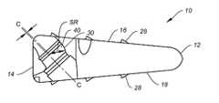
- FIG. 1Dshows a cross-sectional view of the spinal implant of FIG. 1A ;
- FIG. 1Eshows still another cross-sectional view of the spinal implant of FIG. 1A .
- FIG. 2illustrates a perspective side view of an exemplary embodiment of a fixation screw of the present disclosure.
- FIG. 3illustrates an exploded view of an exemplary embodiment of a screwdriver of the present disclosure.
- FIG. 4Aillustrates a top-down view of the inner shaft of the screwdriver of FIG. 3 .
- FIG. 4Billustrates a side perspective view of the inner shaft of FIG. 4A .
- FIG. 4Cillustrates an enlarged, exploded view of the universal joint of the screwdriver of FIG. 3 .
- FIG. 5Aillustrates a cross-sectional view of the screwdriver of FIG. 3 .
- FIG. 5Billustrates a perspective view of a portion of the screwdriver of FIG. 3 .
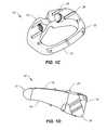
- FIG. 6Aillustrates a perspective view of an exemplary embodiment of an awl instrument with punch of the present disclosure.
- FIG. 6Billustrates a cross-sectional view of the awl instrument and punch of FIG. 6A .
- FIGS. 7A-7Cillustrate perspective views of various designs for the punch of FIG. 6A .
- FIG. 8illustrates a perspective view of an exemplary embodiment of a spinal implant inserter of the present disclosure.
- FIG. 9Aillustrates an enlarged perspective view of a portion of the inserter of FIG. 8 .
- FIG. 9Billustrates a partial cutaway view of a portion of the inserter of FIG. 8 .
- a spinal implantthat is configured for midline insertion into a patient's intervertebral disc space.
- a spinal implantis provided having an upper surface, a lower surface, an anterior portion, a posterior portion and one or more apertures within the anterior portion for receiving at least one fixation element wherein the implant is configured for midline insertion. All or some of the apertures may be configured to permit a predetermined amount of nutation by a fixation element, thus allowing the fixation element to toggle from one position to another.
- the spinal implantmay additionally include anti-migration features.
- the spinal implant 10is configured for midline insertion into a patient's intervertebral disc space.
- the spinal implant 10may be employed in the lumbar or thoracic regions.
- the spinal implant 10may be employed in the cervical region of the spine.
- a cervical versionmay be provided so long as it is appropriately sized and configured, and the surgical approach takes into account this specific cervical design as well as size.
- the spinal implant 10may include anterior and posterior portions 12 , 14 and upper and lower surfaces 16 , 18 profiled to correspond with the intervertebral space to which they are to be secured.
- the upper and lower surfaces 16 , 18may further include surface enhancements 28 , such as for example, teeth, ridges, protrusions, ribs, or fins, to enhance bone attachment, prevent migration and provide more stability.
- the enhancements 28may be formed at about a 30 degree angle with respect to the upper or lower surfaces 16 , 18 of the implant 10 .
- the enhancementscan have an angle between about 25 to about 35 degrees. It is understood, however, that alternative surface modifications, such as surface roughenings, barbs, spikes, bumps, etc., may also be employed.
- biological agentssuch as bone growth factors may be employed to enhance bone attachment, either alone or in combination with the mechanical enhancements described above.
- the spinal implant 10defines a generally wedge shaped structure or arrowhead profile for ease of insertion and to be suitable for a posterior midline insertion approach.
- the implant 10may have rounded edges.
- the anterior portion 12extends into curved sidewalls 20 that intersect with proximal portion 14 at posterolateral corners 22 .
- the posterolateral cornersmay be rounded, as shown, to provide overall smoothness to the implant profile and prevent undesirable damage to surrounding tissue.
- the spinal implant 10may have other shapes depending on the desired implantation site.
- edges of the implant 10may be shaped so as to cooperate with insertion tools to minimize unintended distraction of the vertebral bodies between which the implant 10 is being positioned during implantation.
- projections 52 on the upper surface 16 of the implant 10may be provided to facilitate insertion.
- these projections 52may be used to direct a tool or instrument.
- a pair of projections 52 a, 52 bmay be centrally provided on the upper surface 16 of the implant 10 .
- the projections 52 a, 52 bform a key way K for directing an inserter/distractor instrument's blade, and serves as a guide for such instruments.
- the spinal implant 10 and its componentsmay be formed of any suitable medical grade material, such as biocompatible metals like stainless steel, titanium, titanium alloys, etc. or a medical grade plastic, such as polyetheretherketone (PEEK) or another radiolucent material, ultra high molecular weight polyethylene (UHMWPE), etc. If so desired, the implant 10 may also be formed of a bioresorbable material.
- the bioresorbable materialmay be osteoconductive or osteoinductive (or both).
- the spinal implant 10may include a central opening or lumen 24 extending between the upper and lower surfaces 16 , 18 to facilitate bony ingrowth or fusion between adjacent bone segments, such as vertebral bodies. If so desired, the opening 24 may be used to receive and hold bone graft material, or other biologically active materials like bone cement, bone void filler, bone substitute material, bone chips, demineralized bone matrix, and other similar materials.
- the spinal implant 10may be configured in a way that optimizes the opening 24 such that the ratio of the cage or implant structure to the load bearing area is as large as possible.
- the spinal implant 10may include holes 26 for placement of fixation screws 60 therethrough to secure the spinal implant 10 to adjacent bone tissue.
- the implant 10includes three holes 26 , such as one hole being centrally located (i.e., along the center line), and two laterally located (i.e., beside the center line.)
- the lateral holes 26should be located in a manner that avoids the need to retract vessels during surgery. It has been postulated that extended retraction of vessels during surgery may lead to greater chances for complications to the patient.
- the lateral holes 26should also be positioned so as to provide easier visibility of the surrounding implantation site for the surgeon. In the present embodiment shown in FIG. 1B , the screw holes 26 are closely packed for easier access around vessels.
- FIG. 2illustrates an exemplary fixation device such as a bone screw 60 that may be used with the implants 10 of the present disclosure.
- the bone screw 60can have a head portion 62 and a tip 64 with a threaded shaft 68 in between.
- the bone screw 60may also be used with an anti-backout ring 72 .
- the screw 60may also include a visual marker 66 comprising a groove, band, laser etching, or other similar physical indicator that disappears from view when the screw is fully seated, in order to assist with the insertion process. For example, during use, a groove or band 66 laser marked on the screw head 62 disappears from view when the screw 60 is fully seated within the screw hole 26 of the implant 10 .
- the holes 26may also include visual cues or markers to provide visual feedback to the surgeon that a screw 60 inserted therein is properly seated.
- the visual cuemay comprise a groove 42 around the screw hole 26 , or an indicator arrow 44 that can be seen when the screw 60 is seated fully.
- the visual groove 42may include an etching or a colored band. The visual groove 42 can be utilized to indicate that the screw 60 positioned therein is fully seated or implanted, thereby allowing the screw head 62 to clear the way for the user to view the groove 42 .
- each of the screw holes 26may be provided with one or more of these visual markers (i.e., a visual groove 42 or an indicator arrow 44 , or both).
- the implant 10may comprise any number of holes in any location on the implant 10 .
- one embodiment of the spinal implant 10may employ two of holes 26 that are located on either side of the center of implant 10 .
- the implant 10may comprise other holes for receiving features like a radiologic marker or other imaging marker.
- the spinal implant 10may include bores 50 near the posterolateral corners 22 for receiving an imaging marker (not shown).
- the imaging markermay be formed of tantalum or a radiopaque material.
- the imaging markermay be configured as a rod or other appropriate shape. These imaging markers can assist with placement of the implant 10 by providing visual cues for the surgeon intraoperatively.
- a suitable imaging markeris disclosed in co-owned U.S. Pat. No. 8,870,961, entitled “SPINAL IMPLANT CONFIGURED FOR MIDLINE INSERTION,” filed Nov. 8, 2010, and issued Oct. 28,2014, the contents of which are incorporated herein by reference.
- the holes 26provide a path through which securing means (e.g., fixation elements such as bone screws) may be inserted so as to secure the implant 10 to respective superior and inferior vertebral bodies (not shown).
- the holes 26may be configured to accommodate a variety of securing mechanisms, such as screws, pins, staples, or any other suitable fastening device.
- the holes 26 of the spinal implant 10may be configured to permit a predetermined amount of screw toggle (i.e., angular skew) and enable a lag effect when the fixation screw is inserted and resides inside the hole or lumen 26 .
- the holes 26may be designed to permit a certain degree of nutation by the screw, and thus, the screws may toggle from one position to one or more different positions, for instance, during subsidence.
- the predetermined screw toggle(permitted by the clearance between the lumen, or hole 26 and the screw) promotes locking of the screw to the implant 10 after subsidence subsequent to implantation.
- the predetermined amount of screw togglemay be about 3 to 8 degrees, or about 5 to 6 degrees.
- each of the holes 26may have an opening with a reverse chamfer or overhang feature. This overhang feature enable the surgeon to better guide the insertion and general approach of the fixation screw 60 into the screw hole 26 .
- the apertures 26are configured not to break out onto the upper surface 16 of the implant 10 , and as shown in FIG. 1B the anterior portion 12 has a flat face profile to better match the vertebral anatomy and which contacts bony endplates.
- the openings 26may also include a relief 46 , or cutaway portion, to promote visibility and ease of screw tip access.
- the screw holes 26may be provided on a flat face profile 54 of the implant 10 , in order to better match the vertebral anatomy of the patient.
- the openings 26may each include a countersink 40 .
- the countersink feature's centeris offset to the center axis of the hole 26 , represented by lines C-C in FIG. 1E .
- This offsetrepresented by the arrows of FIG. 1E , allows a countervailing force when the surgeon applies pressure on the fixation screw 60 during insertion, and provides a tactile feedback response to let the surgeon know when the fixation screw's head 62 is properly seated. In other words, this offset causes the screw head 62 to become loaded (i.e., provide feedback) on final positioning.
- a portion of the countersink 40may have a spherical surface 30 .
- the position of the spherical surfacemay be defined by the spherical radius center (represented by arrowed line SR).
- the openings or apertures 26may be configured to provide a visual feedback response to the surgeon.
- the quality and strength of the feedback responsealso depends on the quality of the bone tissue at the area of treatment. Healthy normal bone tissue will obviously provide the best feedback, as unhealthy, diseased or damaged bone tissue would not have sufficient strength to provide the necessary countervailing force.
- the surgeonprepares the implantation site by removing some disc material from the disc space between two adjacent vertebrae.
- the spinal implant 10may be provided to the surgeon with the screws pre-attached, or separately, as desired.
- the surgeonthen places the implant 10 in the desired location of a patient's spine. Once in the correct location, the surgeon can tighten the screws into the surrounding bone tissue, thereby securing the implant 10 .
- the implant 10may be configured to permit a predetermined amount of screw toggle and enable a lag effect when the fixation screw is inserted and resides inside the hole or lumen 26 . Upon tightening, the lag effect may be observed whereby the implant 10 draws bone tissue towards itself, which may promote better fusion.
- the predetermined screw togglepromotes locking of the screw 60 to the implant 10 after subsidence subsequent to implantation.
- the patient's natural movementwill result in settling and subsidence of bone tissue and the implant 10 in situ. It is believed that during this process, the weight exerted upon the implant 10 causes the fixation screws 60 to toggle and consequently lock against one or more surfaces of the holes 26 of the implant 10 .
- the screw headsmay be provided with contours on its underside as previously discussed that allow the screws to nutate and toggle with respect to the contoured holes 26 of the implant 10 .
- Other practitionersmay prefer a more rigid implant that is firmly locked to the adjacent vertebral body.
- the embodiments of implant 10allow either preference.
- the screwsmay be provided without the contour on its underside (i.e., a relatively flat underside) while the opening 26 of the implant 10 would likewise not include a contoured seat or countersink 40 .
- the screws and implant 10may form a rigidly locked construct.
- the underside of the screwsmay also include surfaces features as well in order to provide secure attachment to the implant 10 .
- the angular positioning of the various holesallows the present implant 10 to be of a relatively small size and therefore insertable from a midline approach within the intervertebral spaces of the spine.
- the angular positioning of the holescan assist effective operation of the implant 10 and the ability to “stack” implants in adjacent multilevel procedures without the securing means interfering with each other. Such a feature can be of major significance in some situations and applications.
- the predetermined screw togglepromotes locking of the screw to the implant 10 after subsidence subsequent to implantation.
- the patient's natural movementwill result in settling and subsidence of bone tissue and the implant 10 in situ. It is believed that during this process, the weight exerted upon the implant 10 causes the fixation screws to nutate and/or toggle and eventually lock against one or more surfaces of the holes 26 of the implant 10 .
- FIG. 3shows an exemplary embodiment of a fixed angle screwdriver 100 of the present disclosure, and the inner shaft 110 .
- FIGS. 4A and 4Bshow other perspective views of the inner shaft 110 of the screwdriver 100 .
- the screwdriver 100may have an angled neck portion 102 that has a fixed angle.
- FIG. 4Cshows an enlarged and exploded view of the universal joint assembly 114 used with the inner shaft 110 within the screwdriver 100 .
- FIGS. 5A and 5Billustrate other views of the fixed angle screwdriver 100 that may be use in the lumbar region during the implantation process.
- the neck 102 of the screwdriver 100may also be pre-bent and rigidly fixed.
- the universal joint assembly 114promotes a more narrow diameter construct, without compromising strength, thereby providing the benefits of a single piece instrument that is minimally invasive.
- the single piece instrumentcan be easily ported for cleanability.
- FIGS. 6A and 6Billustrate exemplary embodiments of an angled guided awl 120 with punch 122 of the present disclosure.
- the punch 122may extend in a handle or knob 128 to push the punch through the awl instrument 120 , as shown in cross-section in FIG. 6B .
- the angled guided awl 120can comprise a resected window 126 at an elbow of the instrument 120 to reduce drag and improve cleanability, as shown in FIG. 6A .
- various wire or punch patterns and shapesmay be employed to lower the force requirements for extension and retraction. These reduced surface area wires, or punches 122 A, 122 B, 122 C, may have various configurations such as the ones shown in FIGS. 7A, 7B and 7C .
- the patterns of the exemplary punches/wires shownare configured to maintain flexibility and strength while reducing drag within the awl instrument 120 .
- Both the fixed angle screwdriver 100 and angled guided awl instrument 120are configured to allow easy insertion of the implant 10 in the confined intervertebral space being treated.
- the slim profile and angularity of the instrumentshelps the surgeon navigate around the anatomy to properly position the implant 10 in a minimally invasive manner, without causing unneeded damage to the surrounding tissues.
- FIG. 8illustrates an exemplary embodiment of a spinal implant insertion instrument 200 of the present disclosure.
- the instrument 200may comprise an elongate shaft 202 that extends between a gripping end 210 and a handle end 220 .
- the handle end 220comprises a hand-controlled actuator or wheel 224 that controls movement at the gripping end 210 .
- the gripping end 210comprises at least one fixed arm 214 for grabbing an opening 26 of the spinal implant 10 .
- a movable arm 218is also provided, which allows the user to securely hold the implant 10 during insertion.
- This movable arm 218may be controlled by the actuator wheel 224 , which can be turned left or right to effect movement of the movable arm 218 up and down, to engage with the central opening or hole 26 of the implant 10 .
- the actuator wheel 224being positioned away from the terminal end of the handle end 220 is that the actuator wheel 224 is not in the way of the impaction end, which is the terminal end of the handle end 220 .
Landscapes
- Health & Medical Sciences (AREA)
- Engineering & Computer Science (AREA)
- Biomedical Technology (AREA)
- Orthopedic Medicine & Surgery (AREA)
- Transplantation (AREA)
- Life Sciences & Earth Sciences (AREA)
- Neurology (AREA)
- Oral & Maxillofacial Surgery (AREA)
- Heart & Thoracic Surgery (AREA)
- Veterinary Medicine (AREA)
- Public Health (AREA)
- Animal Behavior & Ethology (AREA)
- General Health & Medical Sciences (AREA)
- Cardiology (AREA)
- Vascular Medicine (AREA)
- Physical Education & Sports Medicine (AREA)
- Surgery (AREA)
- Dentistry (AREA)
- Nuclear Medicine, Radiotherapy & Molecular Imaging (AREA)
- Medical Informatics (AREA)
- Molecular Biology (AREA)
- Prostheses (AREA)
- Surgical Instruments (AREA)
Abstract
Description
Claims (4)
Priority Applications (2)
| Application Number | Priority Date | Filing Date | Title |
|---|---|---|---|
| US14/215,718US9566166B2 (en) | 2013-03-15 | 2014-03-17 | Spinal implant configured for midline insertion and related instruments |
| US15/428,601US10413426B2 (en) | 2013-03-15 | 2017-02-09 | Spinal implant configured for midline insertion and related instruments |
Applications Claiming Priority (2)
| Application Number | Priority Date | Filing Date | Title |
|---|---|---|---|
| US201361793847P | 2013-03-15 | 2013-03-15 | |
| US14/215,718US9566166B2 (en) | 2013-03-15 | 2014-03-17 | Spinal implant configured for midline insertion and related instruments |
Related Child Applications (1)
| Application Number | Title | Priority Date | Filing Date |
|---|---|---|---|
| US15/428,601ContinuationUS10413426B2 (en) | 2013-03-15 | 2017-02-09 | Spinal implant configured for midline insertion and related instruments |
Publications (2)
| Publication Number | Publication Date |
|---|---|
| US20140288655A1 US20140288655A1 (en) | 2014-09-25 |
| US9566166B2true US9566166B2 (en) | 2017-02-14 |
Family
ID=51538010
Family Applications (2)
| Application Number | Title | Priority Date | Filing Date |
|---|---|---|---|
| US14/215,718Expired - Fee RelatedUS9566166B2 (en) | 2013-03-15 | 2014-03-17 | Spinal implant configured for midline insertion and related instruments |
| US15/428,601ActiveUS10413426B2 (en) | 2013-03-15 | 2017-02-09 | Spinal implant configured for midline insertion and related instruments |
Family Applications After (1)
| Application Number | Title | Priority Date | Filing Date |
|---|---|---|---|
| US15/428,601ActiveUS10413426B2 (en) | 2013-03-15 | 2017-02-09 | Spinal implant configured for midline insertion and related instruments |
Country Status (5)
| Country | Link |
|---|---|
| US (2) | US9566166B2 (en) |
| EP (2) | EP2967812B1 (en) |
| AU (2) | AU2014232963B2 (en) |
| ES (1) | ES2861251T3 (en) |
| WO (1) | WO2014145478A1 (en) |
Cited By (25)
| Publication number | Priority date | Publication date | Assignee | Title |
|---|---|---|---|---|
| US11285014B1 (en) | 2020-11-05 | 2022-03-29 | Warsaw Orthopedic, Inc. | Expandable inter-body device, system, and method |
| US11291554B1 (en) | 2021-05-03 | 2022-04-05 | Medtronic, Inc. | Unibody dual expanding interbody implant |
| US11376134B1 (en) | 2020-11-05 | 2022-07-05 | Warsaw Orthopedic, Inc. | Dual expanding spinal implant, system, and method of use |
| US11395743B1 (en) | 2021-05-04 | 2022-07-26 | Warsaw Orthopedic, Inc. | Externally driven expandable interbody and related methods |
| US11517443B2 (en) | 2020-11-05 | 2022-12-06 | Warsaw Orthopedic, Inc. | Dual wedge expandable implant, system and method of use |
| US11517363B2 (en) | 2020-11-05 | 2022-12-06 | Warsaw Orthopedic, Inc. | Screw driver and complimentary screws |
| US11612499B2 (en) | 2021-06-24 | 2023-03-28 | Warsaw Orthopedic, Inc. | Expandable interbody implant |
| US11638653B2 (en) | 2020-11-05 | 2023-05-02 | Warsaw Orthopedic, Inc. | Surgery instruments with a movable handle |
| US11723778B1 (en) | 2021-09-23 | 2023-08-15 | Nofusco Corporation | Vertebral implant system and methods of use |
| US11730608B2 (en) | 2021-07-13 | 2023-08-22 | Warsaw Orthopedic, Inc. | Monoblock expandable interbody implant |
| US11806250B2 (en) | 2018-02-22 | 2023-11-07 | Warsaw Orthopedic, Inc. | Expandable spinal implant system and method of using same |
| US11806247B2 (en) | 2020-06-15 | 2023-11-07 | Nofusco Corporation | Intravertebral implant system and methods of use |
| US11833059B2 (en) | 2020-11-05 | 2023-12-05 | Warsaw Orthopedic, Inc. | Expandable inter-body device, expandable plate system, and associated methods |
| US11850163B2 (en) | 2022-02-01 | 2023-12-26 | Warsaw Orthopedic, Inc. | Interbody implant with adjusting shims |
| US11883300B2 (en) | 2020-06-15 | 2024-01-30 | Nofusco Corporation | Orthopedic implant system and methods of use |
| US11963881B2 (en) | 2020-11-05 | 2024-04-23 | Warsaw Orthopedic, Inc. | Expandable inter-body device, system, and method |
| US12121453B2 (en) | 2020-11-05 | 2024-10-22 | Warsaw Orthopedic, Inc. | Dual wedge expandable implant with eyelets, system, and method of use |
| US12144742B2 (en) | 2020-06-15 | 2024-11-19 | Foundation Surgical Group, Inc. | Implant system and methods of use |
| US12171439B2 (en) | 2020-11-05 | 2024-12-24 | Warsaw Orthopedic, Inc. | Protected drill |
| US12239544B2 (en) | 2020-11-05 | 2025-03-04 | Warsaw Orthopedic, Inc. | Rhomboid shaped implants |
| US12268614B2 (en) | 2021-06-24 | 2025-04-08 | Warsaw Orthopedic, Inc. | Interbody implant with adjusting shims |
| US12295865B2 (en) | 2021-06-24 | 2025-05-13 | Warsaw Orthopedic, Inc. | Expandable interbody implant and corresponding inserter |
| US12318308B2 (en) | 2020-11-05 | 2025-06-03 | Warsaw Orthopedic, Inc. | Dual expandable inter-body device |
| US12414863B2 (en) | 2021-06-24 | 2025-09-16 | Warsaw Orthopedic, Inc. | Expandable interbody implant and corresponding surgical tool |
| US12440349B2 (en) | 2022-02-04 | 2025-10-14 | Warsaw Orthopedic, Inc. | Expandable interbody implant and breakoff screw |
Families Citing this family (14)
| Publication number | Priority date | Publication date | Assignee | Title |
|---|---|---|---|---|
| CN114983546A (en) | 2013-05-13 | 2022-09-02 | 尼奥医疗公司 | Orthopedic implant kit |
| RU2017125255A (en)* | 2014-12-16 | 2019-01-18 | Керамтек Гмбх | INTERDERVERSE CAGES AND INSTALLATION INSTRUMENTS |
| WO2019051260A1 (en) | 2017-09-08 | 2019-03-14 | Pioneer Surgical Technology, Inc. | Intervertebral implants, instruments, and methods |
| USD907771S1 (en) | 2017-10-09 | 2021-01-12 | Pioneer Surgical Technology, Inc. | Intervertebral implant |
| BR112020007853A2 (en)* | 2017-10-20 | 2020-10-13 | Centinel Spine, Llc | porous implantable interbody devices |
| US10893953B2 (en)* | 2018-01-29 | 2021-01-19 | Seth Neubardt | Side pocket spinal fusion cage |
| ES2988747T3 (en) | 2019-07-02 | 2024-11-21 | Neo Medical Sa | System to prevent lateral tension on bone structures resulting from off-axis forces caused by the screwdriver and screw extender |
| US11793558B2 (en) | 2019-08-30 | 2023-10-24 | K2M, Inc. | All in one plate holder and spring loaded awl |
| US11173042B2 (en) | 2019-11-26 | 2021-11-16 | GetSet Surgical SA | Spinal surgery devices, systems, and methods |
| US11273057B2 (en)* | 2019-11-26 | 2022-03-15 | GetSet Surgical SA | Spinal surgery instruments, systems, and methods |
| US11278426B2 (en) | 2019-11-26 | 2022-03-22 | GetSet Surgical SA | Spinal surgery assemblies, systems, and methods |
| EP4216876A2 (en) | 2020-09-24 | 2023-08-02 | Alphatec Spine, Inc. | Composite porous interbodies and methods of manufacture |
| WO2022216566A1 (en)* | 2021-04-04 | 2022-10-13 | Nuvasive, Inc. | Spinal implant with flexible screw lock mechanism |
| US12232790B2 (en) | 2022-12-30 | 2025-02-25 | IvyTech Design LLC | Adjustable angle orthopedic distractor, compressor, and distractor-compressor |
Citations (15)
| Publication number | Priority date | Publication date | Assignee | Title |
|---|---|---|---|---|
| US5624106A (en)* | 1995-11-13 | 1997-04-29 | Weber; Gene | Gripping device |
| US20040236333A1 (en) | 2003-03-21 | 2004-11-25 | Lin Paul S. | Uniplate cervical device |
| US20090264927A1 (en) | 2008-04-14 | 2009-10-22 | Howard Joeseph Ginsberg | Spinous process stabilization device and method |
| US7662175B2 (en) | 2003-06-18 | 2010-02-16 | Jackson Roger P | Upload shank swivel head bone screw spinal implant |
| US7914559B2 (en) | 2006-05-30 | 2011-03-29 | Warsaw Orthopedic, Inc. | Locking device and method employing a posted member to control positioning of a stabilization member of a bone stabilization system |
| WO2011057181A1 (en) | 2009-11-09 | 2011-05-12 | Centinel Spine, Inc. | Spinal implant configured for lateral insertion |
| US20110166611A1 (en) | 2009-11-09 | 2011-07-07 | Centinel Spine, Inc. | Combination distracter and inserter instrument |
| US20110166656A1 (en) | 2009-11-09 | 2011-07-07 | Centinel Spine, Inc. | Spinal implant configured for midline insertion |
| EP2361572A1 (en) | 2010-02-26 | 2011-08-31 | Biedermann Motech GmbH & Co. KG | Implant for stabilizing bones or vertebrae |
| US20110313528A1 (en)* | 2010-06-17 | 2011-12-22 | Aesculap Implant Systems, Llc | Standalone interbody fusion device with locking and release mechanism |
| US20120078373A1 (en) | 2010-09-23 | 2012-03-29 | Thomas Gamache | Stand alone intervertebral fusion device |
| EP2508150A1 (en) | 2011-04-04 | 2012-10-10 | Tambra Surgical Devices, LLC | Adjustable apparatus for inserting an implant |
| US20120277870A1 (en) | 2011-04-29 | 2012-11-01 | Wolters Madeline C | Spinal Interbody Implant With Bone Screw Retention |
| US8740983B1 (en)* | 2009-11-11 | 2014-06-03 | Nuvasive, Inc. | Spinal fusion implants and related methods |
| US8840668B1 (en)* | 2009-11-11 | 2014-09-23 | Nuvasive, Inc. | Spinal implants, instruments and related methods |
Family Cites Families (8)
| Publication number | Priority date | Publication date | Assignee | Title |
|---|---|---|---|---|
| US7635368B2 (en)* | 2001-07-16 | 2009-12-22 | Spinecore, Inc. | Intervertebral spacer device having simultaneously engageable angled perimeters for manipulation using a surgical tool |
| EP1439802A2 (en)* | 2001-10-30 | 2004-07-28 | Osteotech, Inc. | Bone implant and insertion tools |
| US7575580B2 (en)* | 2005-04-15 | 2009-08-18 | Warsaw Orthopedic, Inc. | Instruments, implants and methods for positioning implants into a spinal disc space |
| US20100100138A1 (en)* | 2005-09-21 | 2010-04-22 | Reynolds Joseph E | Endoscopic Insturments and Mehod for Delivery of Spinal Implant |
| US20070213737A1 (en)* | 2006-03-08 | 2007-09-13 | Seaspine, Inc. | Insertion tool for an intervertebral spacer providing multiple angles of insertion |
| US8591587B2 (en)* | 2007-10-30 | 2013-11-26 | Aesculap Implant Systems, Llc | Vertebral body replacement device and method for use to maintain a space between two vertebral bodies within a spine |
| US20120197317A1 (en)* | 2011-02-01 | 2012-08-02 | Alejandro Lezama | Quick release spinal implant insertion device |
| US9358123B2 (en)* | 2011-08-09 | 2016-06-07 | Neuropro Spinal Jaxx, Inc. | Bone fusion device, apparatus and method |
- 2014
- 2014-03-17ESES14763222Tpatent/ES2861251T3/enactiveActive
- 2014-03-17WOPCT/US2014/030251patent/WO2014145478A1/enactiveApplication Filing
- 2014-03-17EPEP14763222.8Apatent/EP2967812B1/enactiveActive
- 2014-03-17AUAU2014232963Apatent/AU2014232963B2/enactiveActive
- 2014-03-17EPEP21161579.4Apatent/EP3906898B1/enactiveActive
- 2014-03-17USUS14/215,718patent/US9566166B2/ennot_activeExpired - Fee Related
- 2017
- 2017-02-09USUS15/428,601patent/US10413426B2/enactiveActive
- 2018
- 2018-09-28AUAU2018101467Apatent/AU2018101467A4/ennot_activeExpired
Patent Citations (16)
| Publication number | Priority date | Publication date | Assignee | Title |
|---|---|---|---|---|
| US5624106A (en)* | 1995-11-13 | 1997-04-29 | Weber; Gene | Gripping device |
| US20040236333A1 (en) | 2003-03-21 | 2004-11-25 | Lin Paul S. | Uniplate cervical device |
| US7662175B2 (en) | 2003-06-18 | 2010-02-16 | Jackson Roger P | Upload shank swivel head bone screw spinal implant |
| US7914559B2 (en) | 2006-05-30 | 2011-03-29 | Warsaw Orthopedic, Inc. | Locking device and method employing a posted member to control positioning of a stabilization member of a bone stabilization system |
| US20090264927A1 (en) | 2008-04-14 | 2009-10-22 | Howard Joeseph Ginsberg | Spinous process stabilization device and method |
| US20110166657A1 (en) | 2009-11-09 | 2011-07-07 | Centinel Spine, Inc. | Spinal implant configured for lateral insertion |
| US20110166611A1 (en) | 2009-11-09 | 2011-07-07 | Centinel Spine, Inc. | Combination distracter and inserter instrument |
| US20110166656A1 (en) | 2009-11-09 | 2011-07-07 | Centinel Spine, Inc. | Spinal implant configured for midline insertion |
| WO2011057181A1 (en) | 2009-11-09 | 2011-05-12 | Centinel Spine, Inc. | Spinal implant configured for lateral insertion |
| US8740983B1 (en)* | 2009-11-11 | 2014-06-03 | Nuvasive, Inc. | Spinal fusion implants and related methods |
| US8840668B1 (en)* | 2009-11-11 | 2014-09-23 | Nuvasive, Inc. | Spinal implants, instruments and related methods |
| EP2361572A1 (en) | 2010-02-26 | 2011-08-31 | Biedermann Motech GmbH & Co. KG | Implant for stabilizing bones or vertebrae |
| US20110313528A1 (en)* | 2010-06-17 | 2011-12-22 | Aesculap Implant Systems, Llc | Standalone interbody fusion device with locking and release mechanism |
| US20120078373A1 (en) | 2010-09-23 | 2012-03-29 | Thomas Gamache | Stand alone intervertebral fusion device |
| EP2508150A1 (en) | 2011-04-04 | 2012-10-10 | Tambra Surgical Devices, LLC | Adjustable apparatus for inserting an implant |
| US20120277870A1 (en) | 2011-04-29 | 2012-11-01 | Wolters Madeline C | Spinal Interbody Implant With Bone Screw Retention |
Non-Patent Citations (2)
| Title |
|---|
| Extended European Search Report dated Sep. 13, 2016, European Application No. 14763222, filed Mar. 17, 2014, pp. 1-7. |
| International Search Report and Written Opinion dated Aug. 27, 2014 issued in International Application No. PCT/US2014/030251, pp. 1-11. |
Cited By (31)
| Publication number | Priority date | Publication date | Assignee | Title |
|---|---|---|---|---|
| US11806250B2 (en) | 2018-02-22 | 2023-11-07 | Warsaw Orthopedic, Inc. | Expandable spinal implant system and method of using same |
| US12036132B2 (en) | 2018-02-22 | 2024-07-16 | Warsaw Orthopedic, Inc. | Expandable spinal implant system and method of using same |
| US12144742B2 (en) | 2020-06-15 | 2024-11-19 | Foundation Surgical Group, Inc. | Implant system and methods of use |
| US11883300B2 (en) | 2020-06-15 | 2024-01-30 | Nofusco Corporation | Orthopedic implant system and methods of use |
| US11806247B2 (en) | 2020-06-15 | 2023-11-07 | Nofusco Corporation | Intravertebral implant system and methods of use |
| US12121453B2 (en) | 2020-11-05 | 2024-10-22 | Warsaw Orthopedic, Inc. | Dual wedge expandable implant with eyelets, system, and method of use |
| US11969196B2 (en) | 2020-11-05 | 2024-04-30 | Warsaw Orthopedic, Inc. | Expandable inter-body device, system, and method |
| US12364529B2 (en) | 2020-11-05 | 2025-07-22 | Warsaw Orthopedic, Inc. | Expandable inter-body device, system, and method |
| US11617658B2 (en) | 2020-11-05 | 2023-04-04 | Warsaw Orthopedic, Inc. | Expandable inter-body device, system and method |
| US11638653B2 (en) | 2020-11-05 | 2023-05-02 | Warsaw Orthopedic, Inc. | Surgery instruments with a movable handle |
| US12318308B2 (en) | 2020-11-05 | 2025-06-03 | Warsaw Orthopedic, Inc. | Dual expandable inter-body device |
| US12239544B2 (en) | 2020-11-05 | 2025-03-04 | Warsaw Orthopedic, Inc. | Rhomboid shaped implants |
| US11517363B2 (en) | 2020-11-05 | 2022-12-06 | Warsaw Orthopedic, Inc. | Screw driver and complimentary screws |
| US11517443B2 (en) | 2020-11-05 | 2022-12-06 | Warsaw Orthopedic, Inc. | Dual wedge expandable implant, system and method of use |
| US11833059B2 (en) | 2020-11-05 | 2023-12-05 | Warsaw Orthopedic, Inc. | Expandable inter-body device, expandable plate system, and associated methods |
| US12171439B2 (en) | 2020-11-05 | 2024-12-24 | Warsaw Orthopedic, Inc. | Protected drill |
| US11285014B1 (en) | 2020-11-05 | 2022-03-29 | Warsaw Orthopedic, Inc. | Expandable inter-body device, system, and method |
| US11963881B2 (en) | 2020-11-05 | 2024-04-23 | Warsaw Orthopedic, Inc. | Expandable inter-body device, system, and method |
| US11564724B2 (en) | 2020-11-05 | 2023-01-31 | Warsaw Orthopedic, Inc. | Expandable inter-body device, system and method |
| US11376134B1 (en) | 2020-11-05 | 2022-07-05 | Warsaw Orthopedic, Inc. | Dual expanding spinal implant, system, and method of use |
| US12053392B2 (en) | 2020-11-05 | 2024-08-06 | Warsaw Orthopedic, Inc. | Expandable inter-body device, expandable plate system, and associated methods |
| US11291554B1 (en) | 2021-05-03 | 2022-04-05 | Medtronic, Inc. | Unibody dual expanding interbody implant |
| US11395743B1 (en) | 2021-05-04 | 2022-07-26 | Warsaw Orthopedic, Inc. | Externally driven expandable interbody and related methods |
| US12268614B2 (en) | 2021-06-24 | 2025-04-08 | Warsaw Orthopedic, Inc. | Interbody implant with adjusting shims |
| US12295865B2 (en) | 2021-06-24 | 2025-05-13 | Warsaw Orthopedic, Inc. | Expandable interbody implant and corresponding inserter |
| US11612499B2 (en) | 2021-06-24 | 2023-03-28 | Warsaw Orthopedic, Inc. | Expandable interbody implant |
| US12414863B2 (en) | 2021-06-24 | 2025-09-16 | Warsaw Orthopedic, Inc. | Expandable interbody implant and corresponding surgical tool |
| US11730608B2 (en) | 2021-07-13 | 2023-08-22 | Warsaw Orthopedic, Inc. | Monoblock expandable interbody implant |
| US11723778B1 (en) | 2021-09-23 | 2023-08-15 | Nofusco Corporation | Vertebral implant system and methods of use |
| US11850163B2 (en) | 2022-02-01 | 2023-12-26 | Warsaw Orthopedic, Inc. | Interbody implant with adjusting shims |
| US12440349B2 (en) | 2022-02-04 | 2025-10-14 | Warsaw Orthopedic, Inc. | Expandable interbody implant and breakoff screw |
Also Published As
| Publication number | Publication date |
|---|---|
| EP2967812A1 (en) | 2016-01-20 |
| EP3906898C0 (en) | 2024-10-30 |
| US20170239061A1 (en) | 2017-08-24 |
| US10413426B2 (en) | 2019-09-17 |
| EP2967812B1 (en) | 2021-03-10 |
| EP2967812A4 (en) | 2016-10-12 |
| AU2014232963A1 (en) | 2015-08-20 |
| US20140288655A1 (en) | 2014-09-25 |
| AU2014232963B2 (en) | 2019-01-03 |
| WO2014145478A1 (en) | 2014-09-18 |
| EP3906898B1 (en) | 2024-10-30 |
| AU2018101467A4 (en) | 2018-10-25 |
| EP3906898A1 (en) | 2021-11-10 |
| ES2861251T3 (en) | 2021-10-06 |
Similar Documents
| Publication | Publication Date | Title |
|---|---|---|
| AU2018101467A4 (en) | Spinal implant configured for midline insertion and related instruments | |
| US20230101457A1 (en) | Spinal implants configured for tissue sparing angle of insertion and related methods | |
| US9918850B2 (en) | Spinal implant configured for midline insertion | |
| US10206786B2 (en) | Spinal implant configured for lateral insertion | |
| US10130491B2 (en) | Spinal implant with attachment system | |
| EP3280361B1 (en) | Spinal implants configured for tissue sparing angle of insertion |
Legal Events
| Date | Code | Title | Description |
|---|---|---|---|
| AS | Assignment | Owner name:CENTINEL SPINE, INC., NEW YORK Free format text:ASSIGNMENT OF ASSIGNORS INTEREST;ASSIGNORS:PARRY, JOHN;VISCOGLIOSI, JOHN J.;SIGNING DATES FROM 20140401 TO 20140609;REEL/FRAME:033065/0238 | |
| STCF | Information on status: patent grant | Free format text:PATENTED CASE | |
| AS | Assignment | Owner name:ATHYRIUM OPPORTUNITIES III ACQUISITION LP, NEW YORK Free format text:SECURITY INTEREST;ASSIGNOR:CENTINEL SPINE, LLC;REEL/FRAME:044909/0412 Effective date:20171219 Owner name:ATHYRIUM OPPORTUNITIES III ACQUISITION LP, NEW YOR Free format text:SECURITY INTEREST;ASSIGNOR:CENTINEL SPINE, LLC;REEL/FRAME:044909/0412 Effective date:20171219 | |
| AS | Assignment | Owner name:CENTINEL SPINE, LLC, NEW YORK Free format text:MERGER;ASSIGNOR:CENTINEL SPINE, INC.;REEL/FRAME:044581/0359 Effective date:20171103 | |
| AS | Assignment | Owner name:ATHYRIUM OPPORTUNITIES III ACQUISITION LP, NEW YOR Free format text:CORRECTIVE ASSIGNMENT TO CORRECT THE U.S. PATENT NUMBER 62/525,071 PREVIOUSLY RECORDED AT REEL: 044909 FRAME: 0412. ASSIGNOR(S) HEREBY CONFIRMS THE SECURITY INTEREST;ASSIGNOR:CENTINEL SPINE, LLC;REEL/FRAME:049012/0168 Effective date:20171219 Owner name:ATHYRIUM OPPORTUNITIES III ACQUISITION LP, NEW YORK Free format text:CORRECTIVE ASSIGNMENT TO CORRECT THE U.S. PATENT NUMBER 62/525,071 PREVIOUSLY RECORDED AT REEL: 044909 FRAME: 0412. ASSIGNOR(S) HEREBY CONFIRMS THE SECURITY INTEREST;ASSIGNOR:CENTINEL SPINE, LLC;REEL/FRAME:049012/0168 Effective date:20171219 | |
| MAFP | Maintenance fee payment | Free format text:PAYMENT OF MAINTENANCE FEE, 4TH YR, SMALL ENTITY (ORIGINAL EVENT CODE: M2551); ENTITY STATUS OF PATENT OWNER: SMALL ENTITY Year of fee payment:4 | |
| AS | Assignment | Owner name:CENTINEL SPINE, LLC, NEW YORK Free format text:RELEASE BY SECURED PARTY;ASSIGNOR:ATHYRIUM OPPORTUNITIES III ACQUISITION LP;REEL/FRAME:055527/0880 Effective date:20210308 | |
| AS | Assignment | Owner name:INNOVATUS LIFE SCIENCES LENDING FUND I, LP, NEW YORK Free format text:SECURITY INTEREST;ASSIGNOR:CENTINEL SPINE, LLC;REEL/FRAME:055533/0519 Effective date:20210308 | |
| AS | Assignment | Owner name:CENTINEL SPINE, LLC, NEW YORK Free format text:RELEASE BY SECURED PARTY;ASSIGNOR:INNOVATUS LIFE SCIENCES LENDING FUND I, LP;REEL/FRAME:066101/0861 Effective date:20231019 Owner name:SILONY MEDICAL CORP, FLORIDA Free format text:ASSIGNMENT OF ASSIGNORS INTEREST;ASSIGNOR:CENTINEL SPINE, LLC;REEL/FRAME:066102/0483 Effective date:20231019 | |
| AS | Assignment | Owner name:SILONY SPINE CORP, FLORIDA Free format text:CHANGE OF NAME;ASSIGNOR:SILONY MEDICAL CORP;REEL/FRAME:066697/0257 Effective date:20240215 | |
| FEPP | Fee payment procedure | Free format text:MAINTENANCE FEE REMINDER MAILED (ORIGINAL EVENT CODE: REM.); ENTITY STATUS OF PATENT OWNER: SMALL ENTITY | |
| AS | Assignment | Owner name:CENTINEL SPINE, LLC, NEW YORK Free format text:RELEASE BY SECURED PARTY;ASSIGNOR:INNOVATUS LIFE SCIENCES LENDING FUND I, LP;REEL/FRAME:070480/0725 Effective date:20250225 | |
| LAPS | Lapse for failure to pay maintenance fees | Free format text:PATENT EXPIRED FOR FAILURE TO PAY MAINTENANCE FEES (ORIGINAL EVENT CODE: EXP.); ENTITY STATUS OF PATENT OWNER: SMALL ENTITY | |
| STCH | Information on status: patent discontinuation | Free format text:PATENT EXPIRED DUE TO NONPAYMENT OF MAINTENANCE FEES UNDER 37 CFR 1.362 | |
| FP | Lapsed due to failure to pay maintenance fee | Effective date:20250214 |