US9566146B2 - Cardiovascular valve and valve housing apparatuses and systems - Google Patents
Cardiovascular valve and valve housing apparatuses and systemsDownload PDFInfo
- Publication number
- US9566146B2 US9566146B2US12/340,189US34018908AUS9566146B2US 9566146 B2US9566146 B2US 9566146B2US 34018908 AUS34018908 AUS 34018908AUS 9566146 B2US9566146 B2US 9566146B2
- Authority
- US
- United States
- Prior art keywords
- valve
- cardiovascular
- assembly
- valve assembly
- housing assembly
- Prior art date
- Legal status (The legal status is an assumption and is not a legal conclusion. Google has not performed a legal analysis and makes no representation as to the accuracy of the status listed.)
- Expired - Fee Related, expires
Links
Images


Classifications
- A—HUMAN NECESSITIES
- A61—MEDICAL OR VETERINARY SCIENCE; HYGIENE
- A61B—DIAGNOSIS; SURGERY; IDENTIFICATION
- A61B17/00—Surgical instruments, devices or methods
- A61B17/11—Surgical instruments, devices or methods for performing anastomosis; Buttons for anastomosis
- A—HUMAN NECESSITIES
- A61—MEDICAL OR VETERINARY SCIENCE; HYGIENE
- A61B—DIAGNOSIS; SURGERY; IDENTIFICATION
- A61B17/00—Surgical instruments, devices or methods
- A61B17/11—Surgical instruments, devices or methods for performing anastomosis; Buttons for anastomosis
- A61B17/115—Staplers for performing anastomosis, e.g. in a single operation
- A61B17/1152—Staplers for performing anastomosis, e.g. in a single operation applying the staples on the outside of the lumen
- A—HUMAN NECESSITIES
- A61—MEDICAL OR VETERINARY SCIENCE; HYGIENE
- A61B—DIAGNOSIS; SURGERY; IDENTIFICATION
- A61B17/00—Surgical instruments, devices or methods
- A61B17/32—Surgical cutting instruments
- A61B17/320016—Endoscopic cutting instruments, e.g. arthroscopes, resectoscopes
- A61B17/32002—Endoscopic cutting instruments, e.g. arthroscopes, resectoscopes with continuously rotating, oscillating or reciprocating cutting instruments
- A—HUMAN NECESSITIES
- A61—MEDICAL OR VETERINARY SCIENCE; HYGIENE
- A61B—DIAGNOSIS; SURGERY; IDENTIFICATION
- A61B17/00—Surgical instruments, devices or methods
- A61B17/32—Surgical cutting instruments
- A61B17/3205—Excision instruments
- A61B17/32053—Punch like cutting instruments, e.g. using a cylindrical or oval knife
- A—HUMAN NECESSITIES
- A61—MEDICAL OR VETERINARY SCIENCE; HYGIENE
- A61B—DIAGNOSIS; SURGERY; IDENTIFICATION
- A61B5/00—Measuring for diagnostic purposes; Identification of persons
- A61B5/103—Measuring devices for testing the shape, pattern, colour, size or movement of the body or parts thereof, for diagnostic purposes
- A61B5/107—Measuring physical dimensions, e.g. size of the entire body or parts thereof
- A61B5/1076—Measuring physical dimensions, e.g. size of the entire body or parts thereof for measuring dimensions inside body cavities, e.g. using catheters
- A—HUMAN NECESSITIES
- A61—MEDICAL OR VETERINARY SCIENCE; HYGIENE
- A61F—FILTERS IMPLANTABLE INTO BLOOD VESSELS; PROSTHESES; DEVICES PROVIDING PATENCY TO, OR PREVENTING COLLAPSING OF, TUBULAR STRUCTURES OF THE BODY, e.g. STENTS; ORTHOPAEDIC, NURSING OR CONTRACEPTIVE DEVICES; FOMENTATION; TREATMENT OR PROTECTION OF EYES OR EARS; BANDAGES, DRESSINGS OR ABSORBENT PADS; FIRST-AID KITS
- A61F2/00—Filters implantable into blood vessels; Prostheses, i.e. artificial substitutes or replacements for parts of the body; Appliances for connecting them with the body; Devices providing patency to, or preventing collapsing of, tubular structures of the body, e.g. stents
- A61F2/02—Prostheses implantable into the body
- A61F2/04—Hollow or tubular parts of organs, e.g. bladders, tracheae, bronchi or bile ducts
- A61F2/06—Blood vessels
- A61F2/064—Blood vessels with special features to facilitate anastomotic coupling
- A—HUMAN NECESSITIES
- A61—MEDICAL OR VETERINARY SCIENCE; HYGIENE
- A61F—FILTERS IMPLANTABLE INTO BLOOD VESSELS; PROSTHESES; DEVICES PROVIDING PATENCY TO, OR PREVENTING COLLAPSING OF, TUBULAR STRUCTURES OF THE BODY, e.g. STENTS; ORTHOPAEDIC, NURSING OR CONTRACEPTIVE DEVICES; FOMENTATION; TREATMENT OR PROTECTION OF EYES OR EARS; BANDAGES, DRESSINGS OR ABSORBENT PADS; FIRST-AID KITS
- A61F2/00—Filters implantable into blood vessels; Prostheses, i.e. artificial substitutes or replacements for parts of the body; Appliances for connecting them with the body; Devices providing patency to, or preventing collapsing of, tubular structures of the body, e.g. stents
- A61F2/02—Prostheses implantable into the body
- A61F2/24—Heart valves ; Vascular valves, e.g. venous valves; Heart implants, e.g. passive devices for improving the function of the native valve or the heart muscle; Transmyocardial revascularisation [TMR] devices; Valves implantable in the body
- A61F2/2412—Heart valves ; Vascular valves, e.g. venous valves; Heart implants, e.g. passive devices for improving the function of the native valve or the heart muscle; Transmyocardial revascularisation [TMR] devices; Valves implantable in the body with soft flexible valve members, e.g. tissue valves shaped like natural valves
- A61F2/2418—Scaffolds therefor, e.g. support stents
- A61M1/10—
- A61M1/1008—
- A61M1/1096—
- A—HUMAN NECESSITIES
- A61—MEDICAL OR VETERINARY SCIENCE; HYGIENE
- A61M—DEVICES FOR INTRODUCING MEDIA INTO, OR ONTO, THE BODY; DEVICES FOR TRANSDUCING BODY MEDIA OR FOR TAKING MEDIA FROM THE BODY; DEVICES FOR PRODUCING OR ENDING SLEEP OR STUPOR
- A61M27/00—Drainage appliance for wounds or the like, i.e. wound drains, implanted drains
- A61M27/002—Implant devices for drainage of body fluids from one part of the body to another
- A61M27/006—Cerebrospinal drainage; Accessories therefor, e.g. valves
- A—HUMAN NECESSITIES
- A61—MEDICAL OR VETERINARY SCIENCE; HYGIENE
- A61M—DEVICES FOR INTRODUCING MEDIA INTO, OR ONTO, THE BODY; DEVICES FOR TRANSDUCING BODY MEDIA OR FOR TAKING MEDIA FROM THE BODY; DEVICES FOR PRODUCING OR ENDING SLEEP OR STUPOR
- A61M60/00—Blood pumps; Devices for mechanical circulatory actuation; Balloon pumps for circulatory assistance
- A61M60/10—Location thereof with respect to the patient's body
- A61M60/122—Implantable pumps or pumping devices, i.e. the blood being pumped inside the patient's body
- A61M60/126—Implantable pumps or pumping devices, i.e. the blood being pumped inside the patient's body implantable via, into, inside, in line, branching on, or around a blood vessel
- A61M60/135—Implantable pumps or pumping devices, i.e. the blood being pumped inside the patient's body implantable via, into, inside, in line, branching on, or around a blood vessel inside a blood vessel, e.g. using grafting
- A61M60/139—Implantable pumps or pumping devices, i.e. the blood being pumped inside the patient's body implantable via, into, inside, in line, branching on, or around a blood vessel inside a blood vessel, e.g. using grafting inside the aorta, e.g. intra-aortic balloon pumps
- A—HUMAN NECESSITIES
- A61—MEDICAL OR VETERINARY SCIENCE; HYGIENE
- A61B—DIAGNOSIS; SURGERY; IDENTIFICATION
- A61B17/00—Surgical instruments, devices or methods
- A61B17/00234—Surgical instruments, devices or methods for minimally invasive surgery
- A—HUMAN NECESSITIES
- A61—MEDICAL OR VETERINARY SCIENCE; HYGIENE
- A61B—DIAGNOSIS; SURGERY; IDENTIFICATION
- A61B17/00—Surgical instruments, devices or methods
- A61B17/00234—Surgical instruments, devices or methods for minimally invasive surgery
- A61B2017/00238—Type of minimally invasive operation
- A61B2017/00243—Type of minimally invasive operation cardiac
- A61B2017/00247—Making holes in the wall of the heart, e.g. laser Myocardial revascularization
- A61B2017/00252—Making holes in the wall of the heart, e.g. laser Myocardial revascularization for by-pass connections, i.e. connections from heart chamber to blood vessel or from blood vessel to blood vessel
- A—HUMAN NECESSITIES
- A61—MEDICAL OR VETERINARY SCIENCE; HYGIENE
- A61B—DIAGNOSIS; SURGERY; IDENTIFICATION
- A61B17/00—Surgical instruments, devices or methods
- A61B17/00234—Surgical instruments, devices or methods for minimally invasive surgery
- A61B2017/00349—Needle-like instruments having hook or barb-like gripping means, e.g. for grasping suture or tissue
- A—HUMAN NECESSITIES
- A61—MEDICAL OR VETERINARY SCIENCE; HYGIENE
- A61B—DIAGNOSIS; SURGERY; IDENTIFICATION
- A61B17/00—Surgical instruments, devices or methods
- A61B2017/00743—Type of operation; Specification of treatment sites
- A61B2017/00778—Operations on blood vessels
- A—HUMAN NECESSITIES
- A61—MEDICAL OR VETERINARY SCIENCE; HYGIENE
- A61B—DIAGNOSIS; SURGERY; IDENTIFICATION
- A61B17/00—Surgical instruments, devices or methods
- A61B17/11—Surgical instruments, devices or methods for performing anastomosis; Buttons for anastomosis
- A61B2017/1107—Surgical instruments, devices or methods for performing anastomosis; Buttons for anastomosis for blood vessels
- A—HUMAN NECESSITIES
- A61—MEDICAL OR VETERINARY SCIENCE; HYGIENE
- A61B—DIAGNOSIS; SURGERY; IDENTIFICATION
- A61B17/00—Surgical instruments, devices or methods
- A61B17/11—Surgical instruments, devices or methods for performing anastomosis; Buttons for anastomosis
- A61B2017/1132—End-to-end connections
- A—HUMAN NECESSITIES
- A61—MEDICAL OR VETERINARY SCIENCE; HYGIENE
- A61B—DIAGNOSIS; SURGERY; IDENTIFICATION
- A61B17/00—Surgical instruments, devices or methods
- A61B17/11—Surgical instruments, devices or methods for performing anastomosis; Buttons for anastomosis
- A61B2017/1135—End-to-side connections, e.g. T- or Y-connections
- A—HUMAN NECESSITIES
- A61—MEDICAL OR VETERINARY SCIENCE; HYGIENE
- A61B—DIAGNOSIS; SURGERY; IDENTIFICATION
- A61B90/00—Instruments, implements or accessories specially adapted for surgery or diagnosis and not covered by any of the groups A61B1/00 - A61B50/00, e.g. for luxation treatment or for protecting wound edges
- A61B90/06—Measuring instruments not otherwise provided for
- A61B2090/061—Measuring instruments not otherwise provided for for measuring dimensions, e.g. length
- A—HUMAN NECESSITIES
- A61—MEDICAL OR VETERINARY SCIENCE; HYGIENE
- A61F—FILTERS IMPLANTABLE INTO BLOOD VESSELS; PROSTHESES; DEVICES PROVIDING PATENCY TO, OR PREVENTING COLLAPSING OF, TUBULAR STRUCTURES OF THE BODY, e.g. STENTS; ORTHOPAEDIC, NURSING OR CONTRACEPTIVE DEVICES; FOMENTATION; TREATMENT OR PROTECTION OF EYES OR EARS; BANDAGES, DRESSINGS OR ABSORBENT PADS; FIRST-AID KITS
- A61F2/00—Filters implantable into blood vessels; Prostheses, i.e. artificial substitutes or replacements for parts of the body; Appliances for connecting them with the body; Devices providing patency to, or preventing collapsing of, tubular structures of the body, e.g. stents
- A61F2/02—Prostheses implantable into the body
- A61F2/24—Heart valves ; Vascular valves, e.g. venous valves; Heart implants, e.g. passive devices for improving the function of the native valve or the heart muscle; Transmyocardial revascularisation [TMR] devices; Valves implantable in the body
- A61F2/2403—Heart valves ; Vascular valves, e.g. venous valves; Heart implants, e.g. passive devices for improving the function of the native valve or the heart muscle; Transmyocardial revascularisation [TMR] devices; Valves implantable in the body with pivoting rigid closure members
- A—HUMAN NECESSITIES
- A61—MEDICAL OR VETERINARY SCIENCE; HYGIENE
- A61F—FILTERS IMPLANTABLE INTO BLOOD VESSELS; PROSTHESES; DEVICES PROVIDING PATENCY TO, OR PREVENTING COLLAPSING OF, TUBULAR STRUCTURES OF THE BODY, e.g. STENTS; ORTHOPAEDIC, NURSING OR CONTRACEPTIVE DEVICES; FOMENTATION; TREATMENT OR PROTECTION OF EYES OR EARS; BANDAGES, DRESSINGS OR ABSORBENT PADS; FIRST-AID KITS
- A61F2/00—Filters implantable into blood vessels; Prostheses, i.e. artificial substitutes or replacements for parts of the body; Appliances for connecting them with the body; Devices providing patency to, or preventing collapsing of, tubular structures of the body, e.g. stents
- A61F2/02—Prostheses implantable into the body
- A61F2/24—Heart valves ; Vascular valves, e.g. venous valves; Heart implants, e.g. passive devices for improving the function of the native valve or the heart muscle; Transmyocardial revascularisation [TMR] devices; Valves implantable in the body
- A61F2/2409—Support rings therefor, e.g. for connecting valves to tissue
- A—HUMAN NECESSITIES
- A61—MEDICAL OR VETERINARY SCIENCE; HYGIENE
- A61F—FILTERS IMPLANTABLE INTO BLOOD VESSELS; PROSTHESES; DEVICES PROVIDING PATENCY TO, OR PREVENTING COLLAPSING OF, TUBULAR STRUCTURES OF THE BODY, e.g. STENTS; ORTHOPAEDIC, NURSING OR CONTRACEPTIVE DEVICES; FOMENTATION; TREATMENT OR PROTECTION OF EYES OR EARS; BANDAGES, DRESSINGS OR ABSORBENT PADS; FIRST-AID KITS
- A61F2/00—Filters implantable into blood vessels; Prostheses, i.e. artificial substitutes or replacements for parts of the body; Appliances for connecting them with the body; Devices providing patency to, or preventing collapsing of, tubular structures of the body, e.g. stents
- A61F2/02—Prostheses implantable into the body
- A61F2/24—Heart valves ; Vascular valves, e.g. venous valves; Heart implants, e.g. passive devices for improving the function of the native valve or the heart muscle; Transmyocardial revascularisation [TMR] devices; Valves implantable in the body
- A61F2/2412—Heart valves ; Vascular valves, e.g. venous valves; Heart implants, e.g. passive devices for improving the function of the native valve or the heart muscle; Transmyocardial revascularisation [TMR] devices; Valves implantable in the body with soft flexible valve members, e.g. tissue valves shaped like natural valves
- A—HUMAN NECESSITIES
- A61—MEDICAL OR VETERINARY SCIENCE; HYGIENE
- A61F—FILTERS IMPLANTABLE INTO BLOOD VESSELS; PROSTHESES; DEVICES PROVIDING PATENCY TO, OR PREVENTING COLLAPSING OF, TUBULAR STRUCTURES OF THE BODY, e.g. STENTS; ORTHOPAEDIC, NURSING OR CONTRACEPTIVE DEVICES; FOMENTATION; TREATMENT OR PROTECTION OF EYES OR EARS; BANDAGES, DRESSINGS OR ABSORBENT PADS; FIRST-AID KITS
- A61F2/00—Filters implantable into blood vessels; Prostheses, i.e. artificial substitutes or replacements for parts of the body; Appliances for connecting them with the body; Devices providing patency to, or preventing collapsing of, tubular structures of the body, e.g. stents
- A61F2/02—Prostheses implantable into the body
- A61F2/24—Heart valves ; Vascular valves, e.g. venous valves; Heart implants, e.g. passive devices for improving the function of the native valve or the heart muscle; Transmyocardial revascularisation [TMR] devices; Valves implantable in the body
- A61F2/2475—Venous valves
- A—HUMAN NECESSITIES
- A61—MEDICAL OR VETERINARY SCIENCE; HYGIENE
- A61F—FILTERS IMPLANTABLE INTO BLOOD VESSELS; PROSTHESES; DEVICES PROVIDING PATENCY TO, OR PREVENTING COLLAPSING OF, TUBULAR STRUCTURES OF THE BODY, e.g. STENTS; ORTHOPAEDIC, NURSING OR CONTRACEPTIVE DEVICES; FOMENTATION; TREATMENT OR PROTECTION OF EYES OR EARS; BANDAGES, DRESSINGS OR ABSORBENT PADS; FIRST-AID KITS
- A61F2/00—Filters implantable into blood vessels; Prostheses, i.e. artificial substitutes or replacements for parts of the body; Appliances for connecting them with the body; Devices providing patency to, or preventing collapsing of, tubular structures of the body, e.g. stents
- A61F2/02—Prostheses implantable into the body
- A61F2/04—Hollow or tubular parts of organs, e.g. bladders, tracheae, bronchi or bile ducts
- A61F2/06—Blood vessels
- A61F2002/068—Modifying the blood flow model, e.g. by diffuser or deflector
- A—HUMAN NECESSITIES
- A61—MEDICAL OR VETERINARY SCIENCE; HYGIENE
- A61F—FILTERS IMPLANTABLE INTO BLOOD VESSELS; PROSTHESES; DEVICES PROVIDING PATENCY TO, OR PREVENTING COLLAPSING OF, TUBULAR STRUCTURES OF THE BODY, e.g. STENTS; ORTHOPAEDIC, NURSING OR CONTRACEPTIVE DEVICES; FOMENTATION; TREATMENT OR PROTECTION OF EYES OR EARS; BANDAGES, DRESSINGS OR ABSORBENT PADS; FIRST-AID KITS
- A61F2/00—Filters implantable into blood vessels; Prostheses, i.e. artificial substitutes or replacements for parts of the body; Appliances for connecting them with the body; Devices providing patency to, or preventing collapsing of, tubular structures of the body, e.g. stents
- A61F2/02—Prostheses implantable into the body
- A61F2/30—Joints
- A61F2002/30001—Additional features of subject-matter classified in A61F2/28, A61F2/30 and subgroups thereof
- A61F2002/30667—Features concerning an interaction with the environment or a particular use of the prosthesis
- A61F2002/3071—Identification means; Administration of patients
- A61F2002/30714—
- A—HUMAN NECESSITIES
- A61—MEDICAL OR VETERINARY SCIENCE; HYGIENE
- A61F—FILTERS IMPLANTABLE INTO BLOOD VESSELS; PROSTHESES; DEVICES PROVIDING PATENCY TO, OR PREVENTING COLLAPSING OF, TUBULAR STRUCTURES OF THE BODY, e.g. STENTS; ORTHOPAEDIC, NURSING OR CONTRACEPTIVE DEVICES; FOMENTATION; TREATMENT OR PROTECTION OF EYES OR EARS; BANDAGES, DRESSINGS OR ABSORBENT PADS; FIRST-AID KITS
- A61F2250/00—Special features of prostheses classified in groups A61F2/00 - A61F2/26 or A61F2/82 or A61F9/00 or A61F11/00 or subgroups thereof
- A61F2250/0058—Additional features; Implant or prostheses properties not otherwise provided for
- A61F2250/0085—Identification means; Administration of patients
- A61F2250/0089—Identification means; Administration of patients coded with symbols, e.g. dots, numbers, letters, words
- A—HUMAN NECESSITIES
- A61—MEDICAL OR VETERINARY SCIENCE; HYGIENE
- A61M—DEVICES FOR INTRODUCING MEDIA INTO, OR ONTO, THE BODY; DEVICES FOR TRANSDUCING BODY MEDIA OR FOR TAKING MEDIA FROM THE BODY; DEVICES FOR PRODUCING OR ENDING SLEEP OR STUPOR
- A61M60/00—Blood pumps; Devices for mechanical circulatory actuation; Balloon pumps for circulatory assistance
- A61M60/80—Constructional details other than related to driving
- A61M60/855—Constructional details other than related to driving of implantable pumps or pumping devices
- A61M60/89—Valves
- A61M60/894—Passive valves, i.e. valves actuated by the blood
Definitions
- Aortic valve replacementis a cardiac surgery procedure that replaces a patient's aortic valve with a prosthetic valve.
- Aortic valve replacementtypically requires open heart surgery, which may be risky and/or impractical for many patients.
- Aortic valve replacementmay not be an option for patients with aortic stenosis, left ventricular outflow obstruction, a heavily calcified ascending aorta, a heavily calcified aortic root, and/or other high risk medical conditions. For example, patients with conditions that preclude a median sternotomy may not be candidates for an aortic valve replacement operation.
- Apical aortic conduitsmay provide a less invasive alternative to aortic valve replacement.
- An apical aortic conduitmay be connected between the apex of the heart and the aorta in a procedure similar to a coronary artery bypass graft.
- Apical aortic conduitsmay improve blood flow between the heart and the aorta by bypassing a diseased or malfunctioning aortic valve.
- Patients who are not eligible for aortic valve replacementmay be treated by using an apical aortic conduit to bypass the valve.
- apical aortic conduitsmay be used in pediatric patients. The native valve may be left in place in pediatric patients to eliminate the need for periodic valve replacements as the patient grows.
- the apical aortic conduitmay maintain the maximum possible function of the native valve while bypassing the restricted flow to lessen stress on the heart and allow more blood flow to the body.
- the apical aortic conduitmay bypass the native valve to allow for extra flow to the aorta while still allowing the maximum flow that the native valve can physiologically handle.
- apical aortic conduitsmay fail or malfunction for various reasons. For example, the conduit material used in an apical aortic conduit may become blocked as a result of kinking. Traditional conduits may also become occluded and obstruct apical flow. Also, apical aortic conduits are typically sutured to the heart and the aorta, and the suturing may cause aneurisms at or near the attachment site. Apical aortic conduits may also cause gastrointestinal complications such as dysphagia and gastric erosion. Furthermore, implanting an apical aortic conduit on a beating heart may result in significant blood loss from the patient.
- a cardiovascular valve assemblymay comprise a housing assembly comprising a first portion and a second portion removably attached to the first portion.
- the cardiovascular valve assemblyalso may comprise a valve positioned within the housing assembly.
- the valvemay be structured to allow fluid to flow through the housing assembly in a single direction.
- the valvemay comprise at least one of a mechanical valve, a biological tissue valve, and a polymeric valve.
- the first portionmay comprise a first connector structured to removably attach the first portion to a first conduit.
- the second portionmay comprise a second connector structured to removably attach the second portion to a second conduit.
- the valvemay be a biological tissue valve comprising a cuff member positioned between the first portion and the second portion.
- the cardiovascular valve assemblymay further comprise at least one coupling structure provided on the second portion and at least one aperture defined in the first portion, the aperture being structured to receive the coupling structure to couple the first portion to the second portion.
- the coupling structure provided on the second portionmay be configured to snap-fit into the aperture defined in the first portion.
- At least one aperturealso may be defined in the valve.
- the apertures defined in the first portion in the valvemay be structured to receive the coupling structure provided on the second portion to couple the first portion and the valve to the second portion.
- the cardiovascular valve assemblymay further comprise a hinged structure constructed to hingedly attach the first portion to the second portion.
- the valve assemblyalso may further comprise at least one seal member positioned between the first portion and the second portion, the seal member being configured to prevent fluid from escaping the housing assembly.
- the first and second portionsmay form a seal to prevent fluid from escaping the housing assembly.
- the cardiovascular valve assemblyalso may comprise at least one identifying indicia to identify a direction for fluid flow.
- the valvemay be structured to prevent the valve from being positioned within the housing assembly in a manner that restricts fluid flow in a desired direction.
- the first portionmay comprise a contoured contact surface structured to contact a contoured contact surface formed on the second portion.
- the cardiovascular valve assemblyalso may comprise a threaded end provided on the first portion and a threaded recess defined in the second portion, the threaded recess being structured to receive the threaded end to removably attach the first portion to the second portion.
- the cardiovascular valve assemblyalso may comprise a retention assembly configured to removably secure the first portion to the second portion.
- the valvemay be sutured to at least one of the first portion and the second portion.
- the first portionalso may be stapled to the second portion.
- the first portion and the second portionmay comprise conical-shaped ends configured to contact at least a portion of the valve.
- a pre-assembled cardiovascular valve assemblymay comprise a conduit, a housing assembly positioned within the conduit, and a valve positioned within the housing assembly.
- the housing assemblymay be sutured to the conduit.
- the valvemay be structured to allow fluid to flow through the housing assembly in a single direction.
- the valvemay comprise at least one of a mechanical valve, a biological tissue valve, and a polymeric valve.
- a systemmay comprise a first conduit dimensioned to be positioned against a first coring site of a cardiovascular organ and a valve assembly removably attached to the first conduit.
- the valve assemblymay comprise a housing assembly comprising a first portion and a second portion removably attached to the first portion and a valve positioned within the housing assembly.
- the valvemay be structured to allow fluid to flow through the housing assembly in a single direction.
- the systemmay comprise a second conduit removably attached to the valve assembly.
- the second conduitmay be dimensioned to be positioned against a second coring site of a cardiovascular organ.
- a cardiovascular valve assemblymay comprise a housing assembly, the housing assembly comprising a first portion comprising at least one coupling structure and a second portion comprising at least one aperture. In certain embodiments, this aperture may be structured to receive the coupling structure to removably attach the first portion to the second portion.
- the cardiovascular valve assemblymay comprise a valve positioned within the housing assembly, at least one seal member positioned between the first portion and the second portion, and at least one identifying indicia configured to indicate a desired direction for fluid flow.
- the seal membermay be configured to prevent fluid from escaping the housing assembly.
- the valvemay be structured to allow fluid to flow through the housing assembly in a single direction. The valve also may be structured to prevent the valve from being positioned within the housing assembly in a manner that restricts fluid flow in a desired direction.
- FIG. 1is a perspective view of a heart, an aorta, and an aorta measuring device according to certain embodiments.
- FIG. 2is a perspective view of an exemplary tube attached to an aorta according to certain embodiments.
- FIG. 3is a perspective view of an exemplary cardiovascular coring device being inserted into the tube illustrated in FIG. 2 .
- FIG. 4is a perspective view of the cardiovascular coring device illustrated in FIG. 3
- FIG. 5is another perspective view of the cardiovascular coring device illustrated in FIG. 3 .
- FIG. 6is a perspective view of a valve scaling the tube illustrated in FIG. 5 against blood flowing out of an opening in an aorta.
- FIG. 7is a perspective view of inserting a cardiovascular conduit section into the tube shown in FIG. 6 .
- FIG. 8is a perspective view of attaching a connector of the cardiovascular conduit system illustrated in FIG. 7 to an aorta.
- FIG. 9is a perspective view of an exemplary cardiovascular conduit system according to certain embodiments.
- FIG. 10is a perspective view of the cardiovascular conduit system illustrated in FIG. 9 .
- FIG. 11is another perspective view of the cardiovascular conduit system illustrated in FIG. 9 .
- FIG. 12is an exploded perspective view of a cardiovascular conduit system according to at least one embodiment.
- FIG. 13is a cross-sectioned side view of a portion of the cardiovascular conduit system illustrated in FIG. 12 .
- FIG. 14is a perspective view of an exemplary cardiovascular valve assembly according to at least one embodiment.
- FIG. 15is a cross-sectioned perspective view of the exemplary cardiovascular valve assembly illustrated in FIG. 14 .
- FIG. 16is an exploded perspective view of an exemplary cardiovascular valve assembly according to at least one embodiment.
- FIG. 17is an additional exploded perspective view of the exemplary cardiovascular valve assembly illustrated in FIG. 16 .
- FIG. 18is a partially assembled perspective view of the exemplary cardiovascular valve assembly illustrated in FIG. 16 .
- FIG. 19is a cross-sectional side view of an exemplary cardiovascular valve assembly according to an additional embodiment.
- FIG. 20is a side view of an exemplary cardiovascular valve assembly according to an additional embodiment.
- FIG. 21is a perspective view of an exemplary cardiovascular valve assembly according to an additional embodiment.
- FIG. 22is a perspective view of an exemplary cardiovascular valve assembly according to an additional embodiment.
- FIG. 23is a perspective view of an exemplary cardiovascular valve assembly according to an additional embodiment.
- FIG. 24is a perspective view of an exemplary cardiovascular valve assembly according to an additional embodiment.
- FIG. 25is a top perspective view of a portion of an exemplary cardiovascular valve assembly according to an additional embodiment.
- FIG. 26is a front view of a portion of the exemplary cardiovascular valve assembly illustrated in FIG. 25 .
- FIG. 27is a perspective view of a portion of the exemplary cardiovascular valve assembly illustrated in FIG. 25 .
- FIG. 28is a back view of a portion of the exemplary cardiovascular valve assembly illustrated in FIG. 25 .
- FIG. 29is a perspective view of an exemplary cardiovascular valve assembly according to an additional embodiment.
- FIG. 30is a perspective view of a portion of an exemplary cardiovascular valve assembly according to an additional embodiment.
- FIG. 31is a perspective view of an exemplary cardiovascular valve assembly according to an additional embodiment.
- FIG. 32is a perspective view of a portion of an exemplary cardiovascular valve assembly according to an additional embodiment.
- FIG. 33is a cross-sectional side view of an exemplary cardiovascular valve assembly according to an additional embodiment.
- FIG. 34is a side view of an exemplary cardiovascular valve assembly according to an additional embodiment.
- a physicianmay implant a cardiovascular conduit system to circumvent a restriction in blood flow.
- a physicianmay use a cardiovascular conduit system to bypass an aortic valve in a patient with aortic valve stenosis.
- a cardiovascular conduit systemmay be used to bypass a pulmonary valve in a patient with pulmonary valve stenosis.
- Physiciansmay also use cardiovascular conduit systems to address various other problems and diseases in a patient's cardiovascular system.
- Cardiovascular conduit systemsmay provide various advantages over prior systems. Physicians may implant a cardiovascular conduit system on a beating heart. Procedures performed on a beating heart may be referred to as off-pump procedures, and off-pump procedures may be less invasive than on-pump procedures (i.e., procedures that require cardiopulmonary bypass).
- cardiovascular conduit systemsmay be used with traditional surgical techniques (e.g., on-pump procedures). In traditional surgical techniques, cardiovascular conduit systems may provide various advantages, such as reduced pump time and smaller incisions.
- Connectors in a cardiovascular conduit systemmay be designed to reduce the risk of aneurisms at the attachment site. The conduit in a cardiovascular conduit system may be kink and occlusion resistant. Cardiovascular conduit systems may also reduce the risk of gastrointestinal complications. Cardiovascular conduit systems may be implanted quickly and minimize patient blood loss. The following disclosure presents numerous other features and advantages of cardiovascular conduit systems.
- FIGS. 1-11illustrate an exemplary process for implanting a cardiovascular conduit system between an apex of a heart and an aorta.
- the first step in implanting a cardiovascular conduit systemmay be measuring the size of a patient's aorta.
- a physicianmay determine the size of the patient's aorta to determine the appropriate sizes for the coring device and aortic connector that will be used in the procedure.
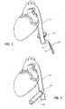
- FIG. 1illustrates an aorta measuring device 100 for measuring a circumference of an aorta 14 .
- Aorta measuring device 100may include a handle 110 , an extension 120 , and a circular measuring member 140 .
- a physicianmay position measuring member 140 around aorta 14 . The physician may then tighten measuring member 140 until it is snug around aorta 14 and capable of measuring the circumference of aorta 14 . The physician may then take a measurement from measuring member 140 .
- Various examples of aorta measuring devicesare illustrated and described in U.S. patent application Ser. No. 12/340,382, filed on 19 Dec. 2008, and entitled “Apparatus and Method for Measuring Blood Vessels,” the disclosure of which is incorporated in its entirety by this reference.
- FIG. 2shows an end of a tube 200 attached to aorta 14 .
- tube 200may provide a sealed interface with aorta 14 during various steps in the process of implanting a cardiovascular conduit system.
- Tube 200may be any suitable size and/or shape.
- tube 200may be cylindrical. In other embodiments, tube 200 may have a rectangular shape, square shape, triangular shape, or any other suitable shape.
- Tube 200may be any suitable length and may be made of any suitable material (e.g., metal, plastic, etc.). Tube 200 may be any suitable type of duct, conduit, pipe, channel, or other enclosure designed to provide a sealed interface between an aorta and various cardiovascular conduit system parts and tools.
- suitable materiale.g., metal, plastic, etc.
- Tube 200may be any suitable type of duct, conduit, pipe, channel, or other enclosure designed to provide a sealed interface between an aorta and various cardiovascular conduit system parts and tools.
- tube 200may be sutured to aorta 14 by sutures 201 .
- Sutures 201may hold tube 200 in place and may help prevent blood leakage at the interface between aorta 14 and tube 200 .
- Tube 200may be secured to aorta 14 using any suitable attachment mechanism in addition to or instead of sutures.
- tube 200may be secured to aorta 14 using a clamp that wraps around aorta 14 .
- a physicianmay press tube 200 against aorta 14 without using any additional attachment mechanism.
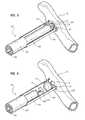
- FIG. 3shows a cross-sectional view of tube 200 .
- FIG. 3also illustrates a cardiovascular coring device 220 being inserted into tube 200 .
- Cardiovascular coring device 220may include a handle 222 , a cutting member 230 , a tissue retraction member 240 , and a corkscrew anchor 242 .
- Corkscrew anchor 242may extend from tissue retraction member 240 .
- Tissue retraction member 240may extend through cutting member 230 and handle 222 .
- a valve 210may be positioned within tube 200 .
- Valve 210may be attached to tube 200 .
- valve 210may be formed as part of tube 200 .
- Valve 210may be a one-way valve that allows cardiovascular coring device 220 to pass through but blocks the flow of blood out of the opening cut in aorta 14 .
- Valve 210may also seal cutting member 230 to tube 200 (as shown in FIG. 5 ) to prevent blood from leaking between tube 200 and cutting member 230 .
- FIGS. 14-25illustrate various examples of valves that may be used in a delivery tube.
- FIG. 4illustrates corkscrew anchor 242 being rotated into aorta 14 at a coring site 243 .
- Corkscrew anchor 242may be secured to the section of tissue that will be removed from aorta 14 .
- Corkscrew anchor 242may prevent the section of tissue from entering the blood stream in aorta 14 .
- Various other types of anchorsmay be secured to cardiovascular organ tissue, as will be discussed in the disclosure corresponding to FIGS. 12-24 .
- FIG. 5shows cardiovascular coring device 220 cutting an opening in aorta 14 .
- Valve 210may seal cutting member 230 to tube 200 while cutting member 230 cuts the opening in aorta 14 .
- Cutting member 230may rotate to cut the opening in aorta 14 .
- cutting member 230may be directly connected to handle 222 , and a physician may rotate cutting member 230 by rotating handle 222 .
- cutting member 230may be rotated by an electric motor or any other suitable rotating mechanism.
- cutting membersmay be any cutting devices suitable for cutting a cardiovascular organ.
- a cutting membermay be a mechanical coring device, as illustrated in FIG. 5 .
- a cutting membermay also be a laser scalpel, a high-frequency ultra-sound device, or any other suitable type of cutting device.
- Cutting membersmay be standalone devices. In other embodiments, a cutting member may be incorporated into a cardiovascular coring device or any other suitable device.
- FIG. 6shows aorta 14 with an opening 16 that was cut open by cutting member 230 .
- Corkscrew anchor 242may be attached to a section of tissue is of aorta 14 that was cut out by cutting member 230 .
- a physicianmay retract cardiovascular coring device 220 to pull tissue 15 away from aorta 14 , as shown in FIG. 6 .
- tissue retraction member 240may be retracted into cutting member 240 before cutting member 240 is retracted through valve 210 .
- tissue retraction member 240may be completely retracted out of cutting member 230 and handle 240 .
- Valve 210may close after cutting member 240 is retracted through valve 210 , thereby preventing blood 18 from flowing out of tube 200 .
- FIG. 7shows a cardiovascular conduit system 250 inserted into tube 200 .
- Cardiovascular conduit system 250may be inserted into tube 200 after cardiovascular coring device 220 is retracted from tube 200 .
- Cardiovascular conduit section 250may include a conduit 252 , a connector 258 , and a connector 254 .
- Various examples of cardiovascular conduits and connectorsare shown and discussed in U.S. patent application Ser. No. 12/340,280, filed on 19 Dec. 2008, and entitled “Systems, Apparatus, and Methods for Cardiovascular Conduits and Connectors,” the disclosure of which is incorporated in its entirety in this reference.
- Connector 254may include expandable members 256 .
- a retractable retaining member 260may hold expandable members 256 in a delivery position while connector 254 is being implanted into aorta 14 .
- Retractable retaining member 260may be attached to handles 264 and 266 to allow a physician to control retractable retaining member 260 .
- a distal end of cardiovascular conduit section 250may be sealed with a clamp 270 .
- Clamp 270may prevent blood from flowing out of cardiovascular conduit section 250 through connector 258 after cardiovascular conduit section 250 is attached to aorta 14 .
- Clamp 270may be any suitable size, shape, and/or configuration.
- valve 210may open to allow cardiovascular conduit section 250 pass through valve 210 .
- cardiovascular conduit section 250may be sealed to tube 200 by valve 210 .
- valve 210may prevent blood from leaking while cardiovascular conduit section 250 is being secured to aorta 14 .
- Connector 254may pass through valve 210 and be partially inserted into opening 16 of aorta 14 such that expandable members 256 extend into aorta 14 .
- a physicianmay then retract retaining member 260 to allow expandable members 256 to deploy and secure cardiovascular conduit system 250 to aorta 14 , as shown in FIG. 8 .
- tube 200may be removed from aorta 14 .
- the suturessuch as sutures. 201 , may be removed and tube 200 may be retracted from the implant site on aorta 14 .
- a physicianmay use a procedure similar to or the same as the procedure for implanting conduit section 250 in aorta 14 for implanting a cardiovascular conduit section in an apex of the heart at the left ventricle.
- a tubemay be attached to an apex of the heart.
- a cutting membermay be inserted through a valve in the tube to cut out a section of the apex of the heart.
- a cardiovascular conduit sectionmay be inserted through the tube and attached to the apex of the heart.
- This procedure (or similar procedures) for implanting cardiovascular conduit sectionsmay be performed on the left ventricle of the heart, the right ventricle of the heart, the pulmonary artery, or any other blood vessel or cardiovascular organ.
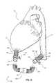
- FIG. 9illustrates a cardiovascular conduit system 299 .
- Cardiovascular conduit system 299may include a cardiovascular conduit section 280 attached to a left ventricle 12 of heart 10 at an apex of heart 10 .
- Cardiovascular conduit section 280may include a connector 282 , a connector 284 , and a conduit 288 .
- Connector 282may be attached to left ventricle 12
- conduit 288may be sealed against blood leakage between connectors 282 and 284 by clamp 286 .
- Cardiovascular conduit system 299may also include cardiovascular conduit section 250 , which includes connector 254 , connector 258 , and conduit 252 . As previously noted, connector 254 may be attached to aorta 14 .
- FIG. 9also shows that cardiovascular conduit system 299 may include a cardiovascular conduit section 290 .
- Cardiovascular conduit section 290may include a connector 292 , a connector 294 , and a valve 296 .
- Connector 292may be dimensioned to attach to connector 284
- connector 294may be dimensioned to attach to connector 258 .
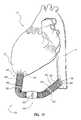
- FIG. 10shows cardiovascular conduit section 290 attached between cardiovascular conduit sections 250 and 280 .
- Connector 292may be attached to connector 284 to join cardiovascular conduit section 280 with cardiovascular conduit section 290 .
- connector 294may be attached to connector 258 to join cardiovascular conduit sections 250 and 290 .
- clamps 270 and 286may be removed to allow blood to begin to flow between left ventricle 12 and aorta 14 .
- FIG. 11shows cardiovascular conduit system 299 with clamps 270 and 286 removed. After clamps 270 and 286 are removed, blood may flow from left ventricle 12 to aorta 14 through valve 296 .
- Cardiovascular conduit systemssuch as cardiovascular conduit system 299 , may be attached between various cardiovascular organs.
- a cardiovascular organmay be any organ in a cardiovascular system.
- Cardiovascular organsinclude the heart and all the blood vessels (e.g., arteries and veins) in the cardiovascular system.
- the aorta and the pulmonary arterymay be referred to as cardiovascular organs.
- blood vesselsmay also be referred to as vascular organs.
- FIG. 12illustrates an exemplary cardiovascular conduit section 299 according to at least one embodiment.
- cardiovascular section 299may comprise a cardiovascular conduit section 250 , a cardiovascular conduit section 280 , and a cardiovascular conduit section 290 .
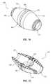
- Cardiovascular conduit section 290may comprise a conduit 291 , a conduit 293 , and a cardiovascular valve assembly 295 .
- a first end 302 of cardiovascular valve assembly 295may be removably attached to conduit 291 .
- a second end 312 of cardiovascular valve assembly 295may be removably attached to conduit 293 .
- Cardiovascular valve assembly 295generally represents any type or form of valve or valve assembly.
- cardiovascular valve assembly 295may comprise a housing having a first portion 300 and a second portion 310 .
- first portion 300may be removably attached to second portion 310 .
- cardiovascular valve assembly 295may comprise a valve 296 and a cuff member 298 .
- Valve 296generally represents any type or form of valve. Examples of valve 296 include, without limitation, a mechanical valve, a biological tissue valve, and a polymeric valve. In certain embodiments, valve 296 may be structured to allow fluid to flow through cardiovascular valve assembly 295 in a single direction. Valve 296 and cuff member 298 may be formed in any suitable shape and size and of any suitable material or combination of materials.
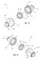
- FIGS. 14 and 15are illustrations of an exemplary cardiovascular valve assembly 295 according to at least one embodiment.
- cardiovascular valve assembly 295may comprise a first portion 300 removably attached to a second portion 310 .
- First portion 300may comprise a first end 302 configured to be removably attached to a conduit, such as conduit 291 in FIG. 13 , and a second end 306 .
- Second portion 310may comprise a first end 312 configured to be removably attached to a conduit, such as conduit 293 in FIG. 13 , and a second end 316 .
- second end 306 of first portion 300may be configured to contact second end 316 of second portion 310 .
- first and second portions of a cardiovascular valve assemblymay be removably attached in any number of ways and configurations.
- first portion 300may comprise a plurality of apertures 304 configured to receive a plurality of coupling structures 314 provided on second portion 310 to removably attach first portion 300 to second portion 310 .
- valve 296may comprise a plurality of apertures 297 configured to receive the plurality of coupling structures 314 provided on second portion 310 to couple both valve 296 and first portion 300 to second portion 310 .
- the apertures 304 , coupling structures 314 , and valve 296 of the cardiovascular valve assembly 295are positioned completely inside of the first and second portions 300 , 310 when assembled (see FIG. 12 ).
- cardiovascular valve assembly 295may comprise at least one identifying indicia configured to identify a desired direction for fluid flow.
- first portion 300may comprise a first identifying indicia 308 .
- second portion 310may comprise a second identifying indicia 318 and valve 296 may comprise a third identifying indicia 313 .
- identifying indicia 308 , 318 , and 313may graphically illustrate the direction of fluid flow through cardiovascular valve assembly 295 .
- valve 296may be structured and/or sized to prevent valve 296 from being positioned within first portion 300 and/or second portion 310 in a manner that restricts fluid flow in a desired direction.
- cuff member 298may be formed in any shape or size and of any suitable material or combination of materials. In at least one embodiment, and as illustrated in FIGS. 12-18 , cuff member 298 may be positioned between, and captured by, first portion 300 and second portion 310 . In addition, in certain embodiments, cuff member 298 may comprise at least one seal member configured to prevent fluid flow from escaping cardiovascular valve assembly 295 . Additionally or alternatively, one or more additional seal members may be positioned between first portion 300 and second portion 310 of cardiovascular valve assembly 295 to prevent fluid from escaping cardiovascular valve assembly 295 .
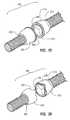
- Cardiovascular valve assembly 295may be formed in any shape and size and of any suitable material or combination of materials.
- cardiovascular valve assembly 295may comprise a substantially conical first portion 300 removably attached to a substantially conical second portion 310 .
- first portion 300may comprise a first end 302 and a substantially planar second end 306 .
- second portion 310may comprise a first end 312 and a substantially planar second end 316 .
- substantially planar second end 306 of first portion 300may be configured to contact substantially planar second end 316 of second portion 310 .
- cardiovascular valve assembly 295may comprise a first portion 300 having a contoured end 306 configured to contact a contoured end 316 provided on second portion 310 .
- contoured end 306 of first portion 300may be formed in a complimentary manner so as to mate with contoured end 316 of second portion 310 .
- Ends 306 and 316 of first and second portions 300 and 310may be formed in any number of additional shapes and/or sizes.
- These contoured surfacesare contoured in the longitudinal direction along the longitudinal axis of the valve assembly 295 , have portions that fit between each other when assembled, and each comprise a plurality of depths relative to the longitudinal axis of the assembly.
- FIG. 21illustrates a cardiovascular valve assembly according to an additional embodiment.
- a cardiovascular valve assemblymay comprise a first portion 400 removably attached to a second portion 410 .
- first portion 400may comprise a first end 402 and a second end 406 .
- second portion 410may comprise a first end 412 and a second end 416 .
- a coupling structure 414may be provided on second end 416 of second portion 410 .
- an aperture 404may be defined in the second end 406 of first portion 400 .
- aperture 404may be structured to receive coupling structure 414 to couple first portion 400 to second portion 410 .
- first portion 400may be hingedly attached to second portion 410 by a hinge structure 420 .
- FIG. 22illustrates an exemplary cardiovascular valve assembly according to an additional embodiment.
- a cardiovascular valve assemblymay comprise a first portion 500 and a second portion 510 .
- second portion 510may be hingedly attached to first portion 500 by hinge structure 520 .
- second portion 510may comprise a coupling structure 514 .
- first portion 500may comprise a recess 504 configured to receive coupling structure 514 provided on second portion 510 to removably attach second portion 510 to first portion 500 .
- first portion 500 and second portion 510may be formed in any shape or size.
- second portion 510may be formed in the shape of a door configured to cover an opening defined in first portion 500 .
- FIG. 23illustrates an exemplary cardiovascular valve assembly according to an additional embodiment.
- a cardiovascular valve assemblymay comprise a first portion 600 having a first end 602 and a second threaded end 606 .
- This exemplary cardiovascular valve assemblymay also comprise a second portion 610 having a first end 612 and a second threaded end 616 .
- second threaded end 616 of second portion 610may be configured to receive second threaded end 606 of first portion 600 to couple, first portion 600 to second portion 612 .
- FIG. 24is an illustration of an exemplary cardiovascular valve assembly according to an additional embodiment.
- a cardiovascular valve assemblymay comprise a first portion 700 having a first end 702 and a second end 706 .
- This cardiovascular valve assemblymay also comprise a second portion 710 having a first end 712 and a second end 716 .
- a plurality of apertures 704may be defined in second end 706 of first portion 700 .
- a plurality of complimentary-shaped coupling structures 714may be provided on second end 716 of second end portion 710 .
- coupling structures 714may be configured to snap-fit into recesses 704 defined in second end 706 of first portion 700 to couple second portion 710 to first portion 700 .
- coupling structure 714 and recesses 704may be formed in any shape and/or size.
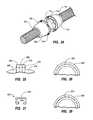
- FIGS. 25-28illustrate a portion of an exemplary cardiovascular valve assembly according to an additional embodiment.
- a first portion 800may be attached to a second portion 810 of a cardiovascular valve assembly by inserting a staple or a retention device 820 through second end 806 of first portion 800 , cuff member 898 , and second end 816 of second portion 810 .
- staple or retention member 820may comprise a body 822 and one or more legs 824 .
- FIG. 29illustrates an exemplary cardiovascular valve assembly according to an additional embodiment.
- a cardiovascular valve assemblymay comprise a first portion 900 having a first end 902 and a second end 906 and a second portion 910 having a first end 912 and a second end 916 .
- the second end 906 of first portion 900may be brought into contact with second end 916 of second portion 910 .
- a plurality of apertures 922may be defined in second end 906 of first portion 900 and second end 916 of second portion 910 .
- first portion 910may be coupled to second portion 920 by inserting one more sutures 920 through apertures 922 defined in both second end 906 of first portion 900 and second end 916 of second portion 910 .
- a first portion of a cardiovascular valve assemblymay be removably attached to a second portion of a cardiovascular valve assembly by rotating the first portion relative to the second portion.
- a first portion 1000 of a cardiovascular valve assemblymay be removably attached to a second portion 1010 of a cardiovascular valve assembly by bringing ends 1006 and 1016 of first and second portions 1000 and 1010 , respectively, into contact with a cuff member 1098 , and then rotating first portion 1000 relative to second portion 1010 until a locking member 1020 locks into place.
- first portion 1000may be removably attached to second portion 1010 .
- FIG. 31illustrates an exemplary cardiovascular valve assembly according to an additional embodiment.
- a cardiovascular valve assemblymay comprise a first conduit 1100 having a first end 1102 and a second conduit 1110 having a first end 1112 .
- ends 1102 and 1112may be substantially conical in shape.
- a valve 1196 and a cuff member 1198may be attached to ends 1102 and 1112 .
- Valve 1196 and cuff member 1198may be attached to ends 1102 and 1112 in any number of ways and configurations.
- valve 1196 and cuff member 1198may be sutured to ends 1102 and 1112 .
- FIG. 32illustrates a portion of an exemplary cardiovascular valve assembly according to an additional embodiment.
- a cardiovascular valve assemblymay comprise a first portion 1200 having an end 1206 and a second portion 1210 having an end 1216 .
- a locking tab assembly 1220may be used to removably attach first portion 1200 to second portion 1210 .
- a hook-shaped body 1222 of locking assembly 1220may be configured to be inserted into an aperture 1228 defined in the end 1216 of second portion 1210 to removably attach first portion 1200 to second portion 1210 .
- the exemplary configuration illustrated in FIG. 32may prevent first portion 1200 from being accidentally detached from second portion 1210 .
- body 1222 of locking assembly 1220may be housed in a recess 1224 defined in first portion 1200 .
- FIG. 33illustrates an exemplary cardiovascular valve assembly according to an additional embodiment.
- a cardiovascular valve assemblymay comprise a conduit 1310 comprising a first connector 1312 and a second connector 1314 .
- a housing assembly 1320may be positioned within conduit 1310 .
- a mechanical valve 1322may be positioned within housing assembly 1320 .
- Housing assembly 1320may be positioned within conduit 1310 in any number of ways and configurations. For example, in certain embodiments, housing assembly 1320 may be sutured to an internal surface 1316 of conduit 1310 .
- the cardiovascular valve assembly illustrated in FIG. 33may be pre-assembled for use by a physician during a medical procedure.
- a cardiovascular valve assemblymay comprise any type or form of valve or valve assembly.
- a cardiovascular valve assemblymay comprise a mechanical valve 1422 .
- mechanical valve 1422may be housed within a housing assembly 1420 comprising a first portion 1424 and a second portion 1426 removably attached to first portion 1424 .
Landscapes
- Health & Medical Sciences (AREA)
- Life Sciences & Earth Sciences (AREA)
- Engineering & Computer Science (AREA)
- Heart & Thoracic Surgery (AREA)
- Biomedical Technology (AREA)
- Veterinary Medicine (AREA)
- Animal Behavior & Ethology (AREA)
- General Health & Medical Sciences (AREA)
- Public Health (AREA)
- Surgery (AREA)
- Cardiology (AREA)
- Vascular Medicine (AREA)
- Medical Informatics (AREA)
- Molecular Biology (AREA)
- Transplantation (AREA)
- Oral & Maxillofacial Surgery (AREA)
- Nuclear Medicine, Radiotherapy & Molecular Imaging (AREA)
- Pulmonology (AREA)
- Gastroenterology & Hepatology (AREA)
- Anesthesiology (AREA)
- Hematology (AREA)
- Orthopedic Medicine & Surgery (AREA)
- Mechanical Engineering (AREA)
- Ophthalmology & Optometry (AREA)
- Otolaryngology (AREA)
- Dentistry (AREA)
- Physics & Mathematics (AREA)
- Biophysics (AREA)
- Pathology (AREA)
- Neurology (AREA)
- Prostheses (AREA)
Abstract
Description
Claims (15)
Priority Applications (3)
| Application Number | Priority Date | Filing Date | Title |
|---|---|---|---|
| US12/340,189US9566146B2 (en) | 2008-12-19 | 2008-12-19 | Cardiovascular valve and valve housing apparatuses and systems |
| PCT/US2009/006581WO2010080107A1 (en) | 2008-12-19 | 2009-12-16 | Cardiovascular valve and valve housing apparatuses and systems |
| US15/398,620US20170112499A1 (en) | 2008-12-19 | 2017-01-04 | Cardiovascular valve and valve housing apparatuses and systems |
Applications Claiming Priority (1)
| Application Number | Priority Date | Filing Date | Title |
|---|---|---|---|
| US12/340,189US9566146B2 (en) | 2008-12-19 | 2008-12-19 | Cardiovascular valve and valve housing apparatuses and systems |
Related Child Applications (1)
| Application Number | Title | Priority Date | Filing Date |
|---|---|---|---|
| US15/398,620ContinuationUS20170112499A1 (en) | 2008-12-19 | 2017-01-04 | Cardiovascular valve and valve housing apparatuses and systems |
Publications (2)
| Publication Number | Publication Date |
|---|---|
| US20100161040A1 US20100161040A1 (en) | 2010-06-24 |
| US9566146B2true US9566146B2 (en) | 2017-02-14 |
Family
ID=41716515
Family Applications (2)
| Application Number | Title | Priority Date | Filing Date |
|---|---|---|---|
| US12/340,189Expired - Fee RelatedUS9566146B2 (en) | 2008-12-19 | 2008-12-19 | Cardiovascular valve and valve housing apparatuses and systems |
| US15/398,620AbandonedUS20170112499A1 (en) | 2008-12-19 | 2017-01-04 | Cardiovascular valve and valve housing apparatuses and systems |
Family Applications After (1)
| Application Number | Title | Priority Date | Filing Date |
|---|---|---|---|
| US15/398,620AbandonedUS20170112499A1 (en) | 2008-12-19 | 2017-01-04 | Cardiovascular valve and valve housing apparatuses and systems |
Country Status (2)
| Country | Link |
|---|---|
| US (2) | US9566146B2 (en) |
| WO (1) | WO2010080107A1 (en) |
Families Citing this family (39)
| Publication number | Priority date | Publication date | Assignee | Title |
|---|---|---|---|---|
| US9138228B2 (en) | 2004-08-11 | 2015-09-22 | Emory University | Vascular conduit device and system for implanting |
| US7846123B2 (en) | 2007-04-24 | 2010-12-07 | Emory University | Conduit device and system for implanting a conduit device in a tissue wall |
| US20110295181A1 (en)* | 2008-03-05 | 2011-12-01 | Hemosphere, Inc. | Implantable and removable customizable body conduit |
| US8728012B2 (en)* | 2008-12-19 | 2014-05-20 | St. Jude Medical, Inc. | Apparatus and method for measuring blood vessels |
| US8905961B2 (en)* | 2008-12-19 | 2014-12-09 | St. Jude Medical, Inc. | Systems, apparatuses, and methods for cardiovascular conduits and connectors |
| US20110118833A1 (en)* | 2009-11-15 | 2011-05-19 | Thoratec Corporation | Attachment device and method |
| US9682180B2 (en)* | 2009-11-15 | 2017-06-20 | Thoratec Corporation | Attachment system, device and method |
| US20110118829A1 (en)* | 2009-11-15 | 2011-05-19 | Thoratec Corporation | Attachment device and method |
| JP6130302B2 (en) | 2011-01-28 | 2017-05-17 | アピカ カーディオヴァスキュラー リミテッド | System for sealing tissue wall stings |
| WO2012106422A2 (en) | 2011-02-01 | 2012-08-09 | Georgia Tech Research Corporation | Systems for implanting and using a conduit within a tissue wall |
| NL1038571C2 (en)* | 2011-02-09 | 2012-08-10 | Bj Innovations & Engineering | BLOOD PUMP, RECOVERY VALVE FOR A BLOOD PUMP AND RECOVERY VALVE FOR A BLOOD PUMP. |
| WO2012116376A1 (en) | 2011-02-25 | 2012-08-30 | Thoratec Corporation | Coupling system, applicator tool, attachment ring and method for connecting a conduit to biological tissue |
| WO2012158919A2 (en) | 2011-05-18 | 2012-11-22 | Thoratec Corporation | Coring knife |
| JP6199866B2 (en) | 2011-09-06 | 2017-09-20 | メリット・メディカル・システムズ・インコーポレイテッドMerit Medical Systems,Inc. | Vascular access system having a connecting portion |
| DE102011117892A1 (en)* | 2011-10-31 | 2013-05-02 | Berlin Heart Gmbh | Connecting element for mounting a blood pump or a cannula on a heart |
| WO2013162741A1 (en) | 2012-04-23 | 2013-10-31 | Thoratec Corporation | Engagement device and method for deployment of anastomotic clips |
| US9301835B2 (en)* | 2012-06-04 | 2016-04-05 | Edwards Lifesciences Corporation | Pre-assembled bioprosthetic valve and sealed conduit |
| EP2934347B1 (en) | 2012-12-21 | 2023-02-22 | Ircad | Applicators for modular magnetic anastomosis device |
| EP2948104B1 (en) | 2013-01-25 | 2019-07-24 | Apica Cardiovascular Limited | Systems for percutaneous access, stabilization and closure of organs |
| EP2968717A4 (en) | 2013-03-15 | 2017-02-22 | Apk Advanced Medical Technologies, Inc. | Devices, systems, and methods for implanting and using a connnector in a tissue wall |
| US20150119977A1 (en)* | 2013-10-30 | 2015-04-30 | The Regents Of The University Of Michigan | System and method to limit cerebral ischemia |
| US10682453B2 (en) | 2013-12-20 | 2020-06-16 | Merit Medical Systems, Inc. | Vascular access system with reinforcement member |
| US10507101B2 (en)* | 2014-10-13 | 2019-12-17 | W. L. Gore & Associates, Inc. | Valved conduit |
| US10485909B2 (en) | 2014-10-31 | 2019-11-26 | Thoratec Corporation | Apical connectors and instruments for use in a heart wall |
| US9937037B2 (en) | 2014-12-18 | 2018-04-10 | W. L. Gore & Associates, Inc. | Prosthetic valved conduits with mechanically coupled leaflets |
| US11383072B2 (en)* | 2017-01-12 | 2022-07-12 | Merit Medical Systems, Inc. | Methods and systems for selection and use of connectors between conduits |
| EP4461262A3 (en) | 2017-01-25 | 2025-02-26 | Merit Medical Systems, Inc. | Systems for facilitating laminar flow between conduits |
| US11026704B2 (en) | 2017-03-06 | 2021-06-08 | Merit Medical Systems, Inc. | Vascular access assembly declotting systems and methods |
| US11406533B2 (en) | 2017-03-17 | 2022-08-09 | W. L. Gore & Associates, Inc. | Integrated aqueous shunt for glaucoma treatment |
| US10925710B2 (en) | 2017-03-24 | 2021-02-23 | Merit Medical Systems, Inc. | Subcutaneous vascular assemblies for improving blood flow and related devices and methods |
| WO2019014444A2 (en) | 2017-07-14 | 2019-01-17 | Merit Medical Systems, Inc. | Releasable conduit connectors |
| US11911585B2 (en) | 2017-07-20 | 2024-02-27 | Merit Medical Systems, Inc. | Methods and systems for coupling conduits |
| US20200237496A1 (en)* | 2017-07-25 | 2020-07-30 | KHOYNEZHAD, Ali | Endovascular replacement of aortic valve, aortic root, and ascending aorta |
| CN111818875B (en) | 2017-10-31 | 2024-05-14 | 爱德华兹生命科学公司 | Valved pipe |
| FR3076702A3 (en)* | 2017-12-28 | 2019-07-19 | Galdino Barbieri | DEVICE FOR CUTTING A BLOOD VESSEL TO MAKE A CONNECTION |
| WO2020047221A1 (en) | 2018-08-29 | 2020-03-05 | W. L. Gore & Associates, Inc. | Drug therapy delivery systems and methods |
| USD977642S1 (en) | 2018-10-29 | 2023-02-07 | W. L. Gore & Associates, Inc. | Pulmonary valve conduit |
| US11678983B2 (en) | 2018-12-12 | 2023-06-20 | W. L. Gore & Associates, Inc. | Implantable component with socket |
| EP3908203A2 (en) | 2019-01-11 | 2021-11-17 | The Regents Of The University Of Colorado | System and method for attaching a fluid conduit to an anatomical structure |
Citations (87)
| Publication number | Priority date | Publication date | Assignee | Title |
|---|---|---|---|---|
| US3232577A (en)* | 1963-05-10 | 1966-02-01 | Frank T Sargent | Gate valve with sectional body |
| US4104005A (en)* | 1976-01-09 | 1978-08-01 | Thermo Electron Corporation | Pneumatic bladder pump having stiffness symmetry |
| US4397617A (en) | 1980-05-12 | 1983-08-09 | Consiglio Nazionale Delle Ricerche | Heart pump for the circulation of blood outside the body of a living subject |
| US4434811A (en)* | 1982-07-28 | 1984-03-06 | The Oilgear Company | Coupling seal and method of assembly |
| US4769031A (en) | 1986-06-25 | 1988-09-06 | Mcgough Edwin C | Ventricular access device and method |
| US4790844A (en) | 1987-01-30 | 1988-12-13 | Yoel Ovil | Replacement of cardiac valves in heart surgery |
| US4816029A (en) | 1981-05-07 | 1989-03-28 | Medtronic, Inc. | Stent for aortic heart valve |
| US4872874A (en) | 1987-05-29 | 1989-10-10 | Taheri Syde A | Method and apparatus for transarterial aortic graft insertion and implantation |
| US5269764A (en)* | 1992-08-21 | 1993-12-14 | Devices For Vascular Intervention, Inc. | Hemostatic gasket and valve assembly |
| US5326373A (en)* | 1985-08-30 | 1994-07-05 | Nippon Zeon Co., Ltd. | Tubular connector |
| US5330528A (en) | 1989-12-01 | 1994-07-19 | British Technology Group Limited | Vascular surgical devices |
| US5332403A (en) | 1992-08-17 | 1994-07-26 | Jack Kolff | LVAD with t-shape and unidirectional valve |
| US5466216A (en) | 1994-04-11 | 1995-11-14 | Gish Biomedical, Inc. | Antegrade/retrograde cardioplegia method and system |
| US5511958A (en) | 1994-02-10 | 1996-04-30 | Baxter International, Inc. | Blood pump system |
| US5755770A (en) | 1995-01-31 | 1998-05-26 | Boston Scientific Corporatiion | Endovascular aortic graft |
| US5776185A (en) | 1994-09-27 | 1998-07-07 | Alessandro Verona | Cardiovascular graft |
| WO1998029146A1 (en) | 1996-12-31 | 1998-07-09 | St. Jude Medical, Inc. | Indicia for prosthetic device |
| US5810708A (en) | 1994-02-07 | 1998-09-22 | Baxter International Inc. | Ventricular assist conduit with externally supported tissue valve |
| US5871537A (en) | 1996-02-13 | 1999-02-16 | Scimed Life Systems, Inc. | Endovascular apparatus |
| US5931842A (en) | 1996-11-07 | 1999-08-03 | Vascular Science Inc. | Methods and apparatus for handling tubing used in medical procedures |
| US5941908A (en) | 1997-04-23 | 1999-08-24 | Vascular Science, Inc. | Artificial medical graft with a releasable retainer |
| US5965086A (en) | 1989-05-05 | 1999-10-12 | Baxter Healthcare Corporation | Method for making sterile connections between fluid conduit tubes |
| US5972017A (en) | 1997-04-23 | 1999-10-26 | Vascular Science Inc. | Method of installing tubular medical graft connectors |
| US6001056A (en) | 1998-11-13 | 1999-12-14 | Baxter International Inc. | Smooth ventricular assist device conduit |
| US6001124A (en) | 1997-10-09 | 1999-12-14 | Vascular Science, Inc. | Oblique-angle graft connectors |
| US6013190A (en) | 1998-01-21 | 2000-01-11 | Vascular Science Inc. | Catheters with integrated lumen and methods of their manufacture and use |
| US6036702A (en) | 1997-04-23 | 2000-03-14 | Vascular Science Inc. | Medical grafting connectors and fasteners |
| US6048362A (en) | 1998-01-12 | 2000-04-11 | St. Jude Medical Cardiovascular Group, Inc. | Fluoroscopically-visible flexible graft structures |
| US6059827A (en)* | 1998-05-04 | 2000-05-09 | Axya Medical, Inc. | Sutureless cardiac valve prosthesis, and devices and methods for implanting them |
| US6068654A (en) | 1997-12-23 | 2000-05-30 | Vascular Science, Inc. | T-shaped medical graft connector |
| US6074416A (en) | 1997-10-09 | 2000-06-13 | St. Jude Medical Cardiovascular Group, Inc. | Wire connector structures for tubular grafts |
| US6113612A (en) | 1998-11-06 | 2000-09-05 | St. Jude Medical Cardiovascular Group, Inc. | Medical anastomosis apparatus |
| US6120432A (en) | 1997-04-23 | 2000-09-19 | Vascular Science Inc. | Medical grafting methods and apparatus |
| US6136007A (en) | 1997-04-17 | 2000-10-24 | St. Jude Medical Cardiovascular Group, Inc, | Apparatus for handling tubing used in medical procedures |
| US6146325A (en) | 1999-06-03 | 2000-11-14 | Arrow International, Inc. | Ventricular assist device |
| US6152956A (en) | 1997-01-28 | 2000-11-28 | Pierce; George E. | Prosthesis for endovascular repair of abdominal aortic aneurysms |
| US6152937A (en) | 1998-11-06 | 2000-11-28 | St. Jude Medical Cardiovascular Group, Inc. | Medical graft connector and methods of making and installing same |
| US6186986B1 (en) | 1998-01-21 | 2001-02-13 | St. Jude Medical Cardiovascular Group, Inc. | Micro-catheters and methods of their manufacture |
| US6200260B1 (en) | 1997-10-09 | 2001-03-13 | Fore Flow Corporation | Implantable heart assist system |
| US6235054B1 (en) | 1998-02-27 | 2001-05-22 | St. Jude Medical Cardiovascular Group, Inc. | Grafts with suture connectors |
| US6261315B1 (en) | 1997-10-28 | 2001-07-17 | St. Jude Medical Cardiovascular Group, Inc. | Tubular body structure marking methods and apparatus |
| US20010027287A1 (en) | 1998-05-26 | 2001-10-04 | Trans Vascular, Inc. | Apparatus for providing coronary retroperfusion and/or left ventricular assist and methods of use |
| US20010049553A1 (en) | 1998-05-08 | 2001-12-06 | Allan Ratner | Prosthetic tublar aortic condit and method for manufacturing the same |
| US6346071B1 (en)* | 1999-07-16 | 2002-02-12 | World Heart Corporation | Inflow conduit assembly for a ventricular assist device |
| US6371982B2 (en) | 1997-10-09 | 2002-04-16 | St. Jude Medical Cardiovascular Group, Inc. | Graft structures with compliance gradients |
| US20020045846A1 (en) | 2000-08-14 | 2002-04-18 | Kaplon Richard J. | Valved apical conduit with trocar for beating-heart ventricular assist device placement |
| US6387037B1 (en) | 1997-10-09 | 2002-05-14 | Orqis Medical Corporation | Implantable heart assist system and method of applying same |
| US6390969B1 (en) | 1997-10-09 | 2002-05-21 | Orqis Medical Corporation | Implantable heart assist system and method of applying same |
| US6416527B1 (en) | 1998-01-28 | 2002-07-09 | St. Jude Medical Cardiovascular Group, Inc. | Vessel cutting device |
| US6443884B1 (en) | 1998-04-06 | 2002-09-03 | Fujio Miyawaki | Ventricular assist device capable of promoting recovery of cardiac function |
| US6450171B1 (en) | 1998-05-01 | 2002-09-17 | Correstore, Inc. | Anterior and inferior segment ventricular restoration apparatus and method |
| US6475222B1 (en) | 1998-11-06 | 2002-11-05 | St. Jude Medical Atg, Inc. | Minimally invasive revascularization apparatus and methods |
| US20020198603A1 (en) | 1998-05-01 | 2002-12-26 | Correstore, Inc. | Anterior segment ventricular restoration apparatus and method |
| US6508252B1 (en) | 1998-11-06 | 2003-01-21 | St. Jude Medical Atg, Inc. | Medical grafting methods and apparatus |
| US6511491B2 (en) | 1999-03-09 | 2003-01-28 | St. Jude Medical Atg, Inc. | Medical grafting methods and apparatus |
| US20030040765A1 (en) | 2001-08-23 | 2003-02-27 | Breznock Eugene Michael | Method and apparatus for trephinating body vessels and hollow organ walls |
| US6610004B2 (en) | 1997-10-09 | 2003-08-26 | Orqis Medical Corporation | Implantable heart assist system and method of applying same |
| US20030176830A1 (en) | 2002-03-13 | 2003-09-18 | Albertus Scheule | Aortic balloon occlusion cannula |
| US20040059178A1 (en) | 2002-09-23 | 2004-03-25 | The Cleveland Clinic Foundation | Apparatus for use with an inflow cannula of a ventricular assist device |
| US20040082910A1 (en) | 2002-10-29 | 2004-04-29 | Constantz Brent R. | Devices and methods for treating aortic valve stenosis |
| US20040097900A1 (en) | 1999-01-11 | 2004-05-20 | Gad Keren | Apparatus and methods for treating congestive heart disease |
| US6746463B1 (en) | 2003-01-27 | 2004-06-08 | Scimed Life Systems, Inc | Device for percutaneous cutting and dilating a stenosis of the aortic valve |
| US20040162608A1 (en) | 2003-02-19 | 2004-08-19 | Axel Haverich | Methods and devices for improving cardiac output |
| US20040193004A1 (en) | 2003-03-28 | 2004-09-30 | Terumo Corporation | Method and apparatus for adjusting a length of the inflow conduit on a ventricular assist device |
| US6805692B2 (en) | 1997-03-06 | 2004-10-19 | Medtronic Ave, Inc. | Aspiration method |
| US20040210202A1 (en) | 2003-04-17 | 2004-10-21 | Weinstein Gerald S. | Aortic cannula |
| US6889082B2 (en) | 1997-10-09 | 2005-05-03 | Orqis Medical Corporation | Implantable heart assist system and method of applying same |
| US20050119688A1 (en) | 2003-10-06 | 2005-06-02 | Bjarne Bergheim | Method and assembly for distal embolic protection |
| US20050149093A1 (en) | 2003-10-30 | 2005-07-07 | Pokorney James L. | Valve bypass graft device, tools, and method |
| US20050154411A1 (en) | 2001-08-23 | 2005-07-14 | Breznock Eugene M. | Method and apparatus for trephinating body vessels and hollow organ walls |
| US20050209502A1 (en) | 2004-03-22 | 2005-09-22 | Deutsches Zentrum Fur Luft-Und Raumfahrt E.V. | Device for connecting a cardiac biventricular assist means |
| US20050251187A1 (en) | 2004-03-23 | 2005-11-10 | Correx, Inc. | Apparatus and method for connecting a conduit to a hollow organ |
| US20050261759A1 (en) | 1999-01-27 | 2005-11-24 | Medtronic, Inc. | Cardiac valve procedure methods and devices |
| US20060014999A1 (en) | 2004-07-19 | 2006-01-19 | Heilman Marlin S | Devices, systems and methods for assisting blood flow |
| US6994666B2 (en) | 2001-06-05 | 2006-02-07 | Edwards Lifesciences Corporation | Non-porous smooth ventricular assist device conduit |
| US20060030747A1 (en) | 2004-07-09 | 2006-02-09 | Kantrowitz Allen B | Synchronization system between aortic valve and cardiac assist device |
| US20060036313A1 (en) | 2004-08-11 | 2006-02-16 | Vassiliades Thomas A | Apicoaortic conduit connector and method for using |
| WO2006019755A2 (en) | 2004-07-22 | 2006-02-23 | Thoratec Corporation | Heart pump connector |
| US7025773B2 (en) | 1999-01-15 | 2006-04-11 | Medtronic, Inc. | Methods and devices for placing a conduit in fluid communication with a target vessel |
| US20060079736A1 (en) | 2004-10-13 | 2006-04-13 | Sing-Fatt Chin | Method and device for percutaneous left ventricular reconstruction |
| US20060089707A1 (en) | 2004-08-11 | 2006-04-27 | Emory University | Vascular conduit device and system for implanting |
| US20060161133A1 (en) | 2003-07-17 | 2006-07-20 | Corazon Technologies, Inc. | Devices and methods for percutaneously treating aortic valve stenosis |
| US20060161193A1 (en) | 2004-12-15 | 2006-07-20 | Correx, Inc. | Apparatus and method for connecting a conduit to a hollow vessel |
| US20070010834A1 (en)* | 2000-04-29 | 2007-01-11 | Sharkawy A A | Components, systems and methods for forming anastomoses using magnetism or other coupling means |
| US20070055357A1 (en)* | 2005-09-02 | 2007-03-08 | Pokorney James L | Prosthetic heart valve housing |
| US20100160847A1 (en) | 2008-12-19 | 2010-06-24 | St. Jude Medical, Inc. | Systems, apparatuses, and methods for cardiovascular conduits and connectors |
| US20100160832A1 (en) | 2008-12-19 | 2010-06-24 | St. Jude Medical, Inc. | Apparatus and method for measuring blood vessels |
Family Cites Families (21)
| Publication number | Priority date | Publication date | Assignee | Title |
|---|---|---|---|---|
| US4086665A (en)* | 1976-12-16 | 1978-05-02 | Thermo Electron Corporation | Artificial blood conduit |
| US5161773A (en)* | 1990-08-01 | 1992-11-10 | Numed, Inc. | Method and apparatus for controlling fluid flow |
| US5224930A (en)* | 1991-01-09 | 1993-07-06 | Endomedix Corporation | Trocar system for facilitating passage of instruments into a body cavity through a minimal access incision |
| US5176687A (en)* | 1991-05-10 | 1993-01-05 | Hasson Harrith M | Disposable pouch container for isolation and retrieval of tissues removed at laparoscopy |
| US5470320A (en)* | 1992-04-10 | 1995-11-28 | Tiefenbrun; Jonathan | Method and related device for obtaining access to a hollow organ |
| CA2102084A1 (en)* | 1992-11-09 | 1994-05-10 | Howard C. Topel | Surgical cutting instrument for coring tissue affixed thereto |
| US5797960A (en)* | 1993-02-22 | 1998-08-25 | Stevens; John H. | Method and apparatus for thoracoscopic intracardiac procedures |
| US5336237A (en)* | 1993-08-25 | 1994-08-09 | Devices For Vascular Intervention, Inc. | Removal of tissue from within a body cavity |
| US5554151A (en)* | 1994-09-27 | 1996-09-10 | United States Surgical Corporation | Specimen retrieval container |
| US5618270A (en)* | 1995-05-26 | 1997-04-08 | Orejola; Wilmo C. | Transthoracic aortic sleeve |
| US5618296A (en)* | 1995-07-24 | 1997-04-08 | Endomedix Corporation/Box 330 | Tissue morcellator system and method |
| US6276661B1 (en)* | 1996-11-06 | 2001-08-21 | Medtronic, Inc. | Pressure actuated introducer valve |
| US5916198A (en)* | 1997-08-05 | 1999-06-29 | Femrx, Inc. | Non-binding surgical valve |
| US6210397B1 (en)* | 1999-01-13 | 2001-04-03 | A-Med Systems, Inc. | Sealing cannula device |
| US6699256B1 (en)* | 1999-06-04 | 2004-03-02 | St. Jude Medical Atg, Inc. | Medical grafting apparatus and methods |
| DE29922034U1 (en)* | 1999-12-15 | 2000-03-02 | Texplorer GmbH, 41334 Nettetal | Clothing, in particular undergarments for people in the military and civil protection sectors |
| US6428424B2 (en)* | 2000-07-14 | 2002-08-06 | Kenneth L. Franco | Golf putter |
| DE10358279A1 (en)* | 2003-12-11 | 2005-07-14 | Karl Storz Gmbh & Co. Kg | Medical instrument for cutting biological and especially human tissue |
| US7597688B1 (en)* | 2004-12-27 | 2009-10-06 | Masson Marcos V | Cannula apparatus with inflatable seal and adjustable length |
| WO2008124650A1 (en)* | 2007-04-06 | 2008-10-16 | Interlace Medical, Inc. | Method, system and device for tissue removal |
| US8414603B2 (en)* | 2007-09-25 | 2013-04-09 | Correx, Inc. | Applicator, assembly, and method for connecting an inlet conduit to a hollow organ |
- 2008
- 2008-12-19USUS12/340,189patent/US9566146B2/ennot_activeExpired - Fee Related
- 2009
- 2009-12-16WOPCT/US2009/006581patent/WO2010080107A1/enactiveApplication Filing
- 2017
- 2017-01-04USUS15/398,620patent/US20170112499A1/ennot_activeAbandoned
Patent Citations (139)
| Publication number | Priority date | Publication date | Assignee | Title |
|---|---|---|---|---|
| US3232577A (en)* | 1963-05-10 | 1966-02-01 | Frank T Sargent | Gate valve with sectional body |
| US4104005A (en)* | 1976-01-09 | 1978-08-01 | Thermo Electron Corporation | Pneumatic bladder pump having stiffness symmetry |
| US4397617A (en) | 1980-05-12 | 1983-08-09 | Consiglio Nazionale Delle Ricerche | Heart pump for the circulation of blood outside the body of a living subject |
| US4816029A (en) | 1981-05-07 | 1989-03-28 | Medtronic, Inc. | Stent for aortic heart valve |
| US4434811A (en)* | 1982-07-28 | 1984-03-06 | The Oilgear Company | Coupling seal and method of assembly |
| US5326373A (en)* | 1985-08-30 | 1994-07-05 | Nippon Zeon Co., Ltd. | Tubular connector |
| US4769031A (en) | 1986-06-25 | 1988-09-06 | Mcgough Edwin C | Ventricular access device and method |
| US4790844A (en) | 1987-01-30 | 1988-12-13 | Yoel Ovil | Replacement of cardiac valves in heart surgery |
| US4872874A (en) | 1987-05-29 | 1989-10-10 | Taheri Syde A | Method and apparatus for transarterial aortic graft insertion and implantation |
| US5965086A (en) | 1989-05-05 | 1999-10-12 | Baxter Healthcare Corporation | Method for making sterile connections between fluid conduit tubes |
| US5330528A (en) | 1989-12-01 | 1994-07-19 | British Technology Group Limited | Vascular surgical devices |
| US5332403A (en) | 1992-08-17 | 1994-07-26 | Jack Kolff | LVAD with t-shape and unidirectional valve |
| US5269764A (en)* | 1992-08-21 | 1993-12-14 | Devices For Vascular Intervention, Inc. | Hemostatic gasket and valve assembly |
| US20010004675A1 (en) | 1994-02-07 | 2001-06-21 | John C. Woodard | Ventricular assist device with valved blood conduit and method of making |
| US5810708A (en) | 1994-02-07 | 1998-09-22 | Baxter International Inc. | Ventricular assist conduit with externally supported tissue valve |
| US5511958A (en) | 1994-02-10 | 1996-04-30 | Baxter International, Inc. | Blood pump system |
| US5599173A (en) | 1994-02-10 | 1997-02-04 | Baxter International, Inc. | Blood pump system |
| US5466216A (en) | 1994-04-11 | 1995-11-14 | Gish Biomedical, Inc. | Antegrade/retrograde cardioplegia method and system |
| US5776185A (en) | 1994-09-27 | 1998-07-07 | Alessandro Verona | Cardiovascular graft |
| US6016810A (en) | 1995-01-31 | 2000-01-25 | Boston Scientific Corporation | Endovasular aortic graft |
| US20020128703A1 (en) | 1995-01-31 | 2002-09-12 | Ravenscroft Adrian C. | Method and apparatus for intraluminally implanting an endovascular aortic graft |
| US5755770A (en) | 1995-01-31 | 1998-05-26 | Boston Scientific Corporatiion | Endovascular aortic graft |
| US6773453B2 (en) | 1995-01-31 | 2004-08-10 | Scimed Life Systems, Inc. | Method and apparatus for intraluminally implanting an endovascular aortic graft |
| US6432131B1 (en) | 1995-01-31 | 2002-08-13 | Boston Scientific Corporation | Method and apparatus for intraluminally implanting an endovascular aortic graft |
| US20040215321A1 (en) | 1996-02-13 | 2004-10-28 | Holman Thomas J. | Endovascular apparatus |
| US20020040235A1 (en) | 1996-02-13 | 2002-04-04 | Holman Thomas J. | Endovascular apparatus |
| US20030220684A1 (en) | 1996-02-13 | 2003-11-27 | Scimed Life Systems, Inc. | Endovascular apparatus |
| US6692523B2 (en) | 1996-02-13 | 2004-02-17 | Scimed Life Systems, Inc. | Endovascular apparatus |
| US20030208257A1 (en) | 1996-02-13 | 2003-11-06 | Holman Thomas J. | Endovascular apparatus |
| US6319276B1 (en) | 1996-02-13 | 2001-11-20 | Scimed Life Systems, Inc. | Endovascular apparatus |
| US5871537A (en) | 1996-02-13 | 1999-02-16 | Scimed Life Systems, Inc. | Endovascular apparatus |
| US6059823A (en) | 1996-02-13 | 2000-05-09 | Scimed Life Systems, Inc. | Endovascular apparatus |
| US20030083738A1 (en) | 1996-02-13 | 2003-05-01 | Holman Thomas J. | Endovascular apparatus |
| US6302905B1 (en) | 1996-11-07 | 2001-10-16 | St. Jude Medical Cardiovascular Group Inc. | Medical grafting methods and apparatus |
| US6206912B1 (en) | 1996-11-07 | 2001-03-27 | St. Jude Medical Anastomotic Technology Group Inc. | Medical grafting methods and apparatus |
| US5976178A (en) | 1996-11-07 | 1999-11-02 | Vascular Science Inc. | Medical grafting methods |
| US5931842A (en) | 1996-11-07 | 1999-08-03 | Vascular Science Inc. | Methods and apparatus for handling tubing used in medical procedures |
| WO1998029146A1 (en) | 1996-12-31 | 1998-07-09 | St. Jude Medical, Inc. | Indicia for prosthetic device |
| US6613087B1 (en)* | 1996-12-31 | 2003-09-02 | St. Jude Medical, Inc. | Indicia for prosthetic device |
| US6669720B1 (en) | 1997-01-28 | 2003-12-30 | George E. Pierce | Prosthesis for endovascular repair of abdominal aortic aneurysms |
| US6152956A (en) | 1997-01-28 | 2000-11-28 | Pierce; George E. | Prosthesis for endovascular repair of abdominal aortic aneurysms |
| US6805692B2 (en) | 1997-03-06 | 2004-10-19 | Medtronic Ave, Inc. | Aspiration method |
| US6136007A (en) | 1997-04-17 | 2000-10-24 | St. Jude Medical Cardiovascular Group, Inc, | Apparatus for handling tubing used in medical procedures |
| US5941908A (en) | 1997-04-23 | 1999-08-24 | Vascular Science, Inc. | Artificial medical graft with a releasable retainer |
| US6702829B2 (en) | 1997-04-23 | 2004-03-09 | St. Jude Medical Atg, Inc. | Medical grafting connectors and fasteners |
| US6186942B1 (en) | 1997-04-23 | 2001-02-13 | St. Jude Medical Cardiovascular Group, Inc. | Medical grafting methods and apparatus |
| US6152945A (en) | 1997-04-23 | 2000-11-28 | St. Jude Medical Cardiovascular Group, Inc. | Tubular medical graft connectors |
| US5972017A (en) | 1997-04-23 | 1999-10-26 | Vascular Science Inc. | Method of installing tubular medical graft connectors |
| US6451033B1 (en) | 1997-04-23 | 2002-09-17 | St. Jude Medical Atg, Inc. | Tubular medical graft connectors |
| US7094248B2 (en) | 1997-04-23 | 2006-08-22 | St. Jude Medical Atg, Inc. | Medical grafting connectors and fasteners |
| US6293965B1 (en) | 1997-04-23 | 2001-09-25 | St. Jude Medical Anastomotic Technology Group, Inc. | Tubular medical graft connectors |
| US6120432A (en) | 1997-04-23 | 2000-09-19 | Vascular Science Inc. | Medical grafting methods and apparatus |
| US6036702A (en) | 1997-04-23 | 2000-03-14 | Vascular Science Inc. | Medical grafting connectors and fasteners |
| US6514196B1 (en) | 1997-04-23 | 2003-02-04 | St. Jude Medical Atg, Inc. | Medical grafting methods and apparatus |
| US6200260B1 (en) | 1997-10-09 | 2001-03-13 | Fore Flow Corporation | Implantable heart assist system |
| US20050256363A1 (en) | 1997-10-09 | 2005-11-17 | Bolling Steven F | Implantable heart assist system and method of applying same |
| US6889082B2 (en) | 1997-10-09 | 2005-05-03 | Orqis Medical Corporation | Implantable heart assist system and method of applying same |
| US6074416A (en) | 1997-10-09 | 2000-06-13 | St. Jude Medical Cardiovascular Group, Inc. | Wire connector structures for tubular grafts |
| US6001124A (en) | 1997-10-09 | 1999-12-14 | Vascular Science, Inc. | Oblique-angle graft connectors |
| US6299575B1 (en) | 1997-10-09 | 2001-10-09 | Orqis Medical Corporation | Implantable heart assist system |
| US6371982B2 (en) | 1997-10-09 | 2002-04-16 | St. Jude Medical Cardiovascular Group, Inc. | Graft structures with compliance gradients |
| US6451048B1 (en) | 1997-10-09 | 2002-09-17 | St. Jude Medical Atg, Inc. | Wire connector structures for tubular grafts |
| US6387037B1 (en) | 1997-10-09 | 2002-05-14 | Orqis Medical Corporation | Implantable heart assist system and method of applying same |
| US6390969B1 (en) | 1997-10-09 | 2002-05-21 | Orqis Medical Corporation | Implantable heart assist system and method of applying same |
| US6610004B2 (en) | 1997-10-09 | 2003-08-26 | Orqis Medical Corporation | Implantable heart assist system and method of applying same |
| US6428464B1 (en) | 1997-10-09 | 2002-08-06 | Orqis Medical Corporation | Implantable heart assist system |
| US6261315B1 (en) | 1997-10-28 | 2001-07-17 | St. Jude Medical Cardiovascular Group, Inc. | Tubular body structure marking methods and apparatus |
| US6068654A (en) | 1997-12-23 | 2000-05-30 | Vascular Science, Inc. | T-shaped medical graft connector |
| US6048362A (en) | 1998-01-12 | 2000-04-11 | St. Jude Medical Cardiovascular Group, Inc. | Fluoroscopically-visible flexible graft structures |
| US6273880B1 (en) | 1998-01-21 | 2001-08-14 | St. Jude Medical Anastomotic Technology Group, Inc. | Catheters with integrated lumen and methods of their manufacture and use |
| US6186986B1 (en) | 1998-01-21 | 2001-02-13 | St. Jude Medical Cardiovascular Group, Inc. | Micro-catheters and methods of their manufacture |
| US6013190A (en) | 1998-01-21 | 2000-01-11 | Vascular Science Inc. | Catheters with integrated lumen and methods of their manufacture and use |
| US6416527B1 (en) | 1998-01-28 | 2002-07-09 | St. Jude Medical Cardiovascular Group, Inc. | Vessel cutting device |
| US6235054B1 (en) | 1998-02-27 | 2001-05-22 | St. Jude Medical Cardiovascular Group, Inc. | Grafts with suture connectors |
| US6443884B1 (en) | 1998-04-06 | 2002-09-03 | Fujio Miyawaki | Ventricular assist device capable of promoting recovery of cardiac function |
| US6450171B1 (en) | 1998-05-01 | 2002-09-17 | Correstore, Inc. | Anterior and inferior segment ventricular restoration apparatus and method |
| US20040181126A1 (en) | 1998-05-01 | 2004-09-16 | Buckberg Gerald D. | Anterior and inferior segment ventricular restoration apparatus and method |
| US20020198603A1 (en) | 1998-05-01 | 2002-12-26 | Correstore, Inc. | Anterior segment ventricular restoration apparatus and method |
| US6059827A (en)* | 1998-05-04 | 2000-05-09 | Axya Medical, Inc. | Sutureless cardiac valve prosthesis, and devices and methods for implanting them |
| US20010049553A1 (en) | 1998-05-08 | 2001-12-06 | Allan Ratner | Prosthetic tublar aortic condit and method for manufacturing the same |
| US6352554B2 (en) | 1998-05-08 | 2002-03-05 | Sulzer Vascutek Limited | Prosthetic tubular aortic conduit and method for manufacturing the same |
| US20010027287A1 (en) | 1998-05-26 | 2001-10-04 | Trans Vascular, Inc. | Apparatus for providing coronary retroperfusion and/or left ventricular assist and methods of use |
| US6533812B2 (en) | 1998-11-06 | 2003-03-18 | St. Jude Medical Atg, Inc. | Medical anastomosis apparatus |
| US6508252B1 (en) | 1998-11-06 | 2003-01-21 | St. Jude Medical Atg, Inc. | Medical grafting methods and apparatus |
| US6440163B1 (en) | 1998-11-06 | 2002-08-27 | St. Jude Medical Atg, Inc. | Medical anastomosis apparatus |
| US6620176B1 (en) | 1998-11-06 | 2003-09-16 | St. Jude Medical Atg, Inc. | Medical graft connector and methods of making and installing same |
| US6599303B1 (en) | 1998-11-06 | 2003-07-29 | St. Jude Medical Atg, Inc. | Medical graft connector and methods of making and installing same |
| US6152937A (en) | 1998-11-06 | 2000-11-28 | St. Jude Medical Cardiovascular Group, Inc. | Medical graft connector and methods of making and installing same |
| US6475222B1 (en) | 1998-11-06 | 2002-11-05 | St. Jude Medical Atg, Inc. | Minimally invasive revascularization apparatus and methods |
| US6113612A (en) | 1998-11-06 | 2000-09-05 | St. Jude Medical Cardiovascular Group, Inc. | Medical anastomosis apparatus |
| US6673084B1 (en) | 1998-11-06 | 2004-01-06 | St. Jude Medical Atg, Inc. | Medical graft connector |
| US6920882B2 (en) | 1998-11-06 | 2005-07-26 | St. Jude Medical Atg, Inc. | Medical grafting methods and apparatus |
| US6309416B1 (en) | 1998-11-06 | 2001-10-30 | St. Jude Medical Cardiovascular Group, Inc. | Medical anastomosis apparatus |
| US6508822B1 (en) | 1998-11-06 | 2003-01-21 | St. Jude Medical Atg, Inc. | Medical graft assembly |
| US6001056A (en) | 1998-11-13 | 1999-12-14 | Baxter International Inc. | Smooth ventricular assist device conduit |
| US20040097900A1 (en) | 1999-01-11 | 2004-05-20 | Gad Keren | Apparatus and methods for treating congestive heart disease |
| US6749598B1 (en) | 1999-01-11 | 2004-06-15 | Flowmedica, Inc. | Apparatus and methods for treating congestive heart disease |
| US7025773B2 (en) | 1999-01-15 | 2006-04-11 | Medtronic, Inc. | Methods and devices for placing a conduit in fluid communication with a target vessel |
| US20050261759A1 (en) | 1999-01-27 | 2005-11-24 | Medtronic, Inc. | Cardiac valve procedure methods and devices |
| US6511491B2 (en) | 1999-03-09 | 2003-01-28 | St. Jude Medical Atg, Inc. | Medical grafting methods and apparatus |
| US6960219B2 (en) | 1999-03-09 | 2005-11-01 | St. Jude Medical Atg, Inc. | Medical grafting methods and apparatus |
| US6146325A (en) | 1999-06-03 | 2000-11-14 | Arrow International, Inc. | Ventricular assist device |
| US6346071B1 (en)* | 1999-07-16 | 2002-02-12 | World Heart Corporation | Inflow conduit assembly for a ventricular assist device |
| US20070010834A1 (en)* | 2000-04-29 | 2007-01-11 | Sharkawy A A | Components, systems and methods for forming anastomoses using magnetism or other coupling means |
| US6726648B2 (en) | 2000-08-14 | 2004-04-27 | The University Of Miami | Valved apical conduit with trocar for beating-heart ventricular assist device placement |
| US20020045846A1 (en) | 2000-08-14 | 2002-04-18 | Kaplon Richard J. | Valved apical conduit with trocar for beating-heart ventricular assist device placement |
| US6994666B2 (en) | 2001-06-05 | 2006-02-07 | Edwards Lifesciences Corporation | Non-porous smooth ventricular assist device conduit |
| US6863677B2 (en) | 2001-08-23 | 2005-03-08 | Eugene Michael Breznock | Method and apparatus for trephinating body vessels and hollow organ walls |
| US20030040765A1 (en) | 2001-08-23 | 2003-02-27 | Breznock Eugene Michael | Method and apparatus for trephinating body vessels and hollow organ walls |
| US20050154411A1 (en) | 2001-08-23 | 2005-07-14 | Breznock Eugene M. | Method and apparatus for trephinating body vessels and hollow organ walls |
| US20030176830A1 (en) | 2002-03-13 | 2003-09-18 | Albertus Scheule | Aortic balloon occlusion cannula |
| US6926689B2 (en) | 2002-03-13 | 2005-08-09 | Albertus Scheule | Aortic balloon occlusion cannula |
| US6802806B2 (en) | 2002-09-23 | 2004-10-12 | Cleveland Clinic Foundation | Apparatus for use with an inflow cannula of ventricular assist device |
| US20040059178A1 (en) | 2002-09-23 | 2004-03-25 | The Cleveland Clinic Foundation | Apparatus for use with an inflow cannula of a ventricular assist device |
| US20040082910A1 (en) | 2002-10-29 | 2004-04-29 | Constantz Brent R. | Devices and methods for treating aortic valve stenosis |
| US20040199191A1 (en) | 2003-01-27 | 2004-10-07 | Leonard Schwartz | Device for percutaneous cutting and dilating a stenosis of the aortic valve |
| US6746463B1 (en) | 2003-01-27 | 2004-06-08 | Scimed Life Systems, Inc | Device for percutaneous cutting and dilating a stenosis of the aortic valve |
| US7029483B2 (en) | 2003-01-27 | 2006-04-18 | Scimed Life Systems, Inc. | Device for percutaneous cutting and dilating a stenosis of the aortic valve |
| US20040162608A1 (en) | 2003-02-19 | 2004-08-19 | Axel Haverich | Methods and devices for improving cardiac output |
| US7077801B2 (en) | 2003-02-19 | 2006-07-18 | Corlife Gbr | Methods and devices for improving cardiac output |
| US20040193004A1 (en) | 2003-03-28 | 2004-09-30 | Terumo Corporation | Method and apparatus for adjusting a length of the inflow conduit on a ventricular assist device |
| US7048681B2 (en) | 2003-03-28 | 2006-05-23 | Terumo Corporation | Method and apparatus for adjusting a length of the inflow conduit on a ventricular assist device |
| US20040210202A1 (en) | 2003-04-17 | 2004-10-21 | Weinstein Gerald S. | Aortic cannula |
| US20060161133A1 (en) | 2003-07-17 | 2006-07-20 | Corazon Technologies, Inc. | Devices and methods for percutaneously treating aortic valve stenosis |
| US20050119688A1 (en) | 2003-10-06 | 2005-06-02 | Bjarne Bergheim | Method and assembly for distal embolic protection |
| US20050149093A1 (en) | 2003-10-30 | 2005-07-07 | Pokorney James L. | Valve bypass graft device, tools, and method |
| US20050209502A1 (en) | 2004-03-22 | 2005-09-22 | Deutsches Zentrum Fur Luft-Und Raumfahrt E.V. | Device for connecting a cardiac biventricular assist means |
| US20050251187A1 (en) | 2004-03-23 | 2005-11-10 | Correx, Inc. | Apparatus and method for connecting a conduit to a hollow organ |
| US20060030747A1 (en) | 2004-07-09 | 2006-02-09 | Kantrowitz Allen B | Synchronization system between aortic valve and cardiac assist device |
| US20060014999A1 (en) | 2004-07-19 | 2006-01-19 | Heilman Marlin S | Devices, systems and methods for assisting blood flow |
| US20060074271A1 (en)* | 2004-07-22 | 2006-04-06 | Cotter Christopher J | Heart pump connector |
| WO2006019755A2 (en) | 2004-07-22 | 2006-02-23 | Thoratec Corporation | Heart pump connector |
| US20060089707A1 (en) | 2004-08-11 | 2006-04-27 | Emory University | Vascular conduit device and system for implanting |
| US20060036313A1 (en) | 2004-08-11 | 2006-02-16 | Vassiliades Thomas A | Apicoaortic conduit connector and method for using |
| US20060079736A1 (en) | 2004-10-13 | 2006-04-13 | Sing-Fatt Chin | Method and device for percutaneous left ventricular reconstruction |
| US20060161193A1 (en) | 2004-12-15 | 2006-07-20 | Correx, Inc. | Apparatus and method for connecting a conduit to a hollow vessel |
| US20070055357A1 (en)* | 2005-09-02 | 2007-03-08 | Pokorney James L | Prosthetic heart valve housing |
| US20100160847A1 (en) | 2008-12-19 | 2010-06-24 | St. Jude Medical, Inc. | Systems, apparatuses, and methods for cardiovascular conduits and connectors |
| US20100160832A1 (en) | 2008-12-19 | 2010-06-24 | St. Jude Medical, Inc. | Apparatus and method for measuring blood vessels |
Non-Patent Citations (39)
Also Published As
| Publication number | Publication date |
|---|---|
| US20100161040A1 (en) | 2010-06-24 |
| WO2010080107A1 (en) | 2010-07-15 |
| US20170112499A1 (en) | 2017-04-27 |
Similar Documents
| Publication | Publication Date | Title |
|---|---|---|
| US9566146B2 (en) | Cardiovascular valve and valve housing apparatuses and systems | |
| US11666314B2 (en) | Method and apparatus for closing a hole in cardiac tissue | |
| US11027103B2 (en) | Conduit device and system for implanting a conduit device in a tissue wall | |
| US7717844B2 (en) | Method and apparatus for stabilization and positioning during surgery | |
| US10499949B2 (en) | Systems for implanting and using a conduit within a tissue wall | |
| US20110260449A1 (en) | Apical access and control devices | |
| JP2014523282A (en) | Minimally invasive repair of heart valve leaflets | |
| US20100160939A1 (en) | Systems, apparatuses, and methods for cardiovascular cutting devices and valves | |
| US10314956B2 (en) | Hollow plug | |
| CN108348666A (en) | Inflow Cannula and Flow Assist Systems | |
| HK1197359A (en) | Minimally invasive repair of heart valve leaflets |
Legal Events
| Date | Code | Title | Description |
|---|---|---|---|
| AS | Assignment | Owner name:ST. JUDE MEDICAL, INC.,MINNESOTA Free format text:ASSIGNMENT OF ASSIGNORS INTEREST;ASSIGNORS:BRAIDO, PETER N.;ALKHATIB, YOUSEF F.;REEL/FRAME:022122/0001 Effective date:20090116 Owner name:ST. JUDE MEDICAL, INC., MINNESOTA Free format text:ASSIGNMENT OF ASSIGNORS INTEREST;ASSIGNORS:BRAIDO, PETER N.;ALKHATIB, YOUSEF F.;REEL/FRAME:022122/0001 Effective date:20090116 | |
| STCF | Information on status: patent grant | Free format text:PATENTED CASE | |
| AS | Assignment | Owner name:ST. JUDE MEDICAL, LLC, MINNESOTA Free format text:MERGER AND CHANGE OF NAME;ASSIGNORS:VAULT MERGER SUB, INC.;ST. JUDE MEDICAL, INC.;ST. JUDE MEDICAL, INC.;REEL/FRAME:049269/0713 Effective date:20170104 | |
| MAFP | Maintenance fee payment | Free format text:PAYMENT OF MAINTENANCE FEE, 4TH YEAR, LARGE ENTITY (ORIGINAL EVENT CODE: M1551); ENTITY STATUS OF PATENT OWNER: LARGE ENTITY Year of fee payment:4 | |
| FEPP | Fee payment procedure | Free format text:MAINTENANCE FEE REMINDER MAILED (ORIGINAL EVENT CODE: REM.); ENTITY STATUS OF PATENT OWNER: LARGE ENTITY | |
| LAPS | Lapse for failure to pay maintenance fees | Free format text:PATENT EXPIRED FOR FAILURE TO PAY MAINTENANCE FEES (ORIGINAL EVENT CODE: EXP.); ENTITY STATUS OF PATENT OWNER: LARGE ENTITY | |
| STCH | Information on status: patent discontinuation | Free format text:PATENT EXPIRED DUE TO NONPAYMENT OF MAINTENANCE FEES UNDER 37 CFR 1.362 | |
| FP | Lapsed due to failure to pay maintenance fee | Effective date:20250214 |