US9565727B2 - LED lighting apparatus with first and second colour LEDs - Google Patents
LED lighting apparatus with first and second colour LEDsDownload PDFInfo
- Publication number
- US9565727B2 US9565727B2US15/136,599US201615136599AUS9565727B2US 9565727 B2US9565727 B2US 9565727B2US 201615136599 AUS201615136599 AUS 201615136599AUS 9565727 B2US9565727 B2US 9565727B2
- Authority
- US
- United States
- Prior art keywords
- led
- leds
- power supply
- coupled
- light engine
- Prior art date
- Legal status (The legal status is an assumption and is not a legal conclusion. Google has not performed a legal analysis and makes no representation as to the accuracy of the status listed.)
- Active
Links
Images


Classifications
- H05B33/0827—
- H—ELECTRICITY
- H05—ELECTRIC TECHNIQUES NOT OTHERWISE PROVIDED FOR
- H05B—ELECTRIC HEATING; ELECTRIC LIGHT SOURCES NOT OTHERWISE PROVIDED FOR; CIRCUIT ARRANGEMENTS FOR ELECTRIC LIGHT SOURCES, IN GENERAL
- H05B45/00—Circuit arrangements for operating light-emitting diodes [LED]
- H05B45/30—Driver circuits
- F21K9/50—
- F—MECHANICAL ENGINEERING; LIGHTING; HEATING; WEAPONS; BLASTING
- F21—LIGHTING
- F21K—NON-ELECTRIC LIGHT SOURCES USING LUMINESCENCE; LIGHT SOURCES USING ELECTROCHEMILUMINESCENCE; LIGHT SOURCES USING CHARGES OF COMBUSTIBLE MATERIAL; LIGHT SOURCES USING SEMICONDUCTOR DEVICES AS LIGHT-GENERATING ELEMENTS; LIGHT SOURCES NOT OTHERWISE PROVIDED FOR
- F21K9/00—Light sources using semiconductor devices as light-generating elements, e.g. using light-emitting diodes [LED] or lasers
- F21K9/60—Optical arrangements integrated in the light source, e.g. for improving the colour rendering index or the light extraction
- F21S4/003—
- F—MECHANICAL ENGINEERING; LIGHTING; HEATING; WEAPONS; BLASTING
- F21—LIGHTING
- F21S—NON-PORTABLE LIGHTING DEVICES; SYSTEMS THEREOF; VEHICLE LIGHTING DEVICES SPECIALLY ADAPTED FOR VEHICLE EXTERIORS
- F21S4/00—Lighting devices or systems using a string or strip of light sources
- F21S4/20—Lighting devices or systems using a string or strip of light sources with light sources held by or within elongate supports
- F—MECHANICAL ENGINEERING; LIGHTING; HEATING; WEAPONS; BLASTING
- F21—LIGHTING
- F21V—FUNCTIONAL FEATURES OR DETAILS OF LIGHTING DEVICES OR SYSTEMS THEREOF; STRUCTURAL COMBINATIONS OF LIGHTING DEVICES WITH OTHER ARTICLES, NOT OTHERWISE PROVIDED FOR
- F21V23/00—Arrangement of electric circuit elements in or on lighting devices
- F21V23/003—Arrangement of electric circuit elements in or on lighting devices the elements being electronics drivers or controllers for operating the light source, e.g. for a LED array
- F21V23/004—Arrangement of electric circuit elements in or on lighting devices the elements being electronics drivers or controllers for operating the light source, e.g. for a LED array arranged on a substrate, e.g. a printed circuit board
- F21V23/005—Arrangement of electric circuit elements in or on lighting devices the elements being electronics drivers or controllers for operating the light source, e.g. for a LED array arranged on a substrate, e.g. a printed circuit board the substrate is supporting also the light source
- F—MECHANICAL ENGINEERING; LIGHTING; HEATING; WEAPONS; BLASTING
- F21—LIGHTING
- F21V—FUNCTIONAL FEATURES OR DETAILS OF LIGHTING DEVICES OR SYSTEMS THEREOF; STRUCTURAL COMBINATIONS OF LIGHTING DEVICES WITH OTHER ARTICLES, NOT OTHERWISE PROVIDED FOR
- F21V23/00—Arrangement of electric circuit elements in or on lighting devices
- F21V23/04—Arrangement of electric circuit elements in or on lighting devices the elements being switches
- H—ELECTRICITY
- H01—ELECTRIC ELEMENTS
- H01L—SEMICONDUCTOR DEVICES NOT COVERED BY CLASS H10
- H01L25/00—Assemblies consisting of a plurality of semiconductor or other solid state devices
- H01L25/03—Assemblies consisting of a plurality of semiconductor or other solid state devices all the devices being of a type provided for in a single subclass of subclasses H10B, H10D, H10F, H10H, H10K or H10N, e.g. assemblies of rectifier diodes
- H01L25/04—Assemblies consisting of a plurality of semiconductor or other solid state devices all the devices being of a type provided for in a single subclass of subclasses H10B, H10D, H10F, H10H, H10K or H10N, e.g. assemblies of rectifier diodes the devices not having separate containers
- H01L25/075—Assemblies consisting of a plurality of semiconductor or other solid state devices all the devices being of a type provided for in a single subclass of subclasses H10B, H10D, H10F, H10H, H10K or H10N, e.g. assemblies of rectifier diodes the devices not having separate containers the devices being of a type provided for in group H10H20/00
- H01L25/0753—Assemblies consisting of a plurality of semiconductor or other solid state devices all the devices being of a type provided for in a single subclass of subclasses H10B, H10D, H10F, H10H, H10K or H10N, e.g. assemblies of rectifier diodes the devices not having separate containers the devices being of a type provided for in group H10H20/00 the devices being arranged next to each other
- H05B33/0803—
- H05B33/0845—
- H05B33/0857—
- H—ELECTRICITY
- H05—ELECTRIC TECHNIQUES NOT OTHERWISE PROVIDED FOR
- H05B—ELECTRIC HEATING; ELECTRIC LIGHT SOURCES NOT OTHERWISE PROVIDED FOR; CIRCUIT ARRANGEMENTS FOR ELECTRIC LIGHT SOURCES, IN GENERAL
- H05B45/00—Circuit arrangements for operating light-emitting diodes [LED]
- H05B45/40—Details of LED load circuits
- H05B45/44—Details of LED load circuits with an active control inside an LED matrix
- H05B45/46—Details of LED load circuits with an active control inside an LED matrix having LEDs disposed in parallel lines
- H—ELECTRICITY
- H05—ELECTRIC TECHNIQUES NOT OTHERWISE PROVIDED FOR
- H05K—PRINTED CIRCUITS; CASINGS OR CONSTRUCTIONAL DETAILS OF ELECTRIC APPARATUS; MANUFACTURE OF ASSEMBLAGES OF ELECTRICAL COMPONENTS
- H05K1/00—Printed circuits
- H05K1/02—Details
- H05K1/03—Use of materials for the substrate
- H05K1/05—Insulated conductive substrates, e.g. insulated metal substrate
- F—MECHANICAL ENGINEERING; LIGHTING; HEATING; WEAPONS; BLASTING
- F21—LIGHTING
- F21Y—INDEXING SCHEME ASSOCIATED WITH SUBCLASSES F21K, F21L, F21S and F21V, RELATING TO THE FORM OR THE KIND OF THE LIGHT SOURCES OR OF THE COLOUR OF THE LIGHT EMITTED
- F21Y2105/00—Planar light sources
- F21Y2105/10—Planar light sources comprising a two-dimensional array of point-like light-generating elements
- F—MECHANICAL ENGINEERING; LIGHTING; HEATING; WEAPONS; BLASTING
- F21—LIGHTING
- F21Y—INDEXING SCHEME ASSOCIATED WITH SUBCLASSES F21K, F21L, F21S and F21V, RELATING TO THE FORM OR THE KIND OF THE LIGHT SOURCES OR OF THE COLOUR OF THE LIGHT EMITTED
- F21Y2115/00—Light-generating elements of semiconductor light sources
- F21Y2115/10—Light-emitting diodes [LED]
- H—ELECTRICITY
- H01—ELECTRIC ELEMENTS
- H01L—SEMICONDUCTOR DEVICES NOT COVERED BY CLASS H10
- H01L2924/00—Indexing scheme for arrangements or methods for connecting or disconnecting semiconductor or solid-state bodies as covered by H01L24/00
- H01L2924/0001—Technical content checked by a classifier
- H01L2924/0002—Not covered by any one of groups H01L24/00, H01L24/00 and H01L2224/00
- H—ELECTRICITY
- H05—ELECTRIC TECHNIQUES NOT OTHERWISE PROVIDED FOR
- H05B—ELECTRIC HEATING; ELECTRIC LIGHT SOURCES NOT OTHERWISE PROVIDED FOR; CIRCUIT ARRANGEMENTS FOR ELECTRIC LIGHT SOURCES, IN GENERAL
- H05B45/00—Circuit arrangements for operating light-emitting diodes [LED]
- H05B45/20—Controlling the colour of the light
- H—ELECTRICITY
- H05—ELECTRIC TECHNIQUES NOT OTHERWISE PROVIDED FOR
- H05B—ELECTRIC HEATING; ELECTRIC LIGHT SOURCES NOT OTHERWISE PROVIDED FOR; CIRCUIT ARRANGEMENTS FOR ELECTRIC LIGHT SOURCES, IN GENERAL
- H05B45/00—Circuit arrangements for operating light-emitting diodes [LED]
- H05B45/30—Driver circuits
- H05B45/32—Pulse-control circuits
- H05B45/325—Pulse-width modulation [PWM]
- H—ELECTRICITY
- H05—ELECTRIC TECHNIQUES NOT OTHERWISE PROVIDED FOR
- H05B—ELECTRIC HEATING; ELECTRIC LIGHT SOURCES NOT OTHERWISE PROVIDED FOR; CIRCUIT ARRANGEMENTS FOR ELECTRIC LIGHT SOURCES, IN GENERAL
- H05B45/00—Circuit arrangements for operating light-emitting diodes [LED]
- H05B45/30—Driver circuits
- H05B45/37—Converter circuits
- H05B45/3725—Switched mode power supply [SMPS]
- H—ELECTRICITY
- H05—ELECTRIC TECHNIQUES NOT OTHERWISE PROVIDED FOR
- H05K—PRINTED CIRCUITS; CASINGS OR CONSTRUCTIONAL DETAILS OF ELECTRIC APPARATUS; MANUFACTURE OF ASSEMBLAGES OF ELECTRICAL COMPONENTS
- H05K2201/00—Indexing scheme relating to printed circuits covered by H05K1/00
- H05K2201/09—Shape and layout
- H05K2201/09209—Shape and layout details of conductors
- H05K2201/0929—Conductive planes
- H05K2201/09309—Core having two or more power planes; Capacitive laminate of two power planes
- H—ELECTRICITY
- H05—ELECTRIC TECHNIQUES NOT OTHERWISE PROVIDED FOR
- H05K—PRINTED CIRCUITS; CASINGS OR CONSTRUCTIONAL DETAILS OF ELECTRIC APPARATUS; MANUFACTURE OF ASSEMBLAGES OF ELECTRICAL COMPONENTS
- H05K2201/00—Indexing scheme relating to printed circuits covered by H05K1/00
- H05K2201/09—Shape and layout
- H05K2201/09818—Shape or layout details not covered by a single group of H05K2201/09009 - H05K2201/09809
- H05K2201/09972—Partitioned, e.g. portions of a PCB dedicated to different functions; Boundary lines therefore; Portions of a PCB being processed separately or differently
- H—ELECTRICITY
- H05—ELECTRIC TECHNIQUES NOT OTHERWISE PROVIDED FOR
- H05K—PRINTED CIRCUITS; CASINGS OR CONSTRUCTIONAL DETAILS OF ELECTRIC APPARATUS; MANUFACTURE OF ASSEMBLAGES OF ELECTRICAL COMPONENTS
- H05K2201/00—Indexing scheme relating to printed circuits covered by H05K1/00
- H05K2201/10—Details of components or other objects attached to or integrated in a printed circuit board
- H05K2201/10007—Types of components
- H05K2201/10106—Light emitting diode [LED]
- H—ELECTRICITY
- H10—SEMICONDUCTOR DEVICES; ELECTRIC SOLID-STATE DEVICES NOT OTHERWISE PROVIDED FOR
- H10H—INORGANIC LIGHT-EMITTING SEMICONDUCTOR DEVICES HAVING POTENTIAL BARRIERS
- H10H20/00—Individual inorganic light-emitting semiconductor devices having potential barriers, e.g. light-emitting diodes [LED]
- H10H20/80—Constructional details
- H10H20/85—Packages
- H10H20/857—Interconnections, e.g. lead-frames, bond wires or solder balls
Definitions
- the present inventionrelates generally to a lighting apparatus, and more particularly to a lighting apparatus comprising a plurality of light emitting diodes.
- Fluorescent lighting systemsare widely used and many fluorescent lighting systems are designed to accommodate long slender fluorescent tubes.
- LED based lighting systemsmay be more efficient, have a longer lifespan, and be more controllable (e.g. colour, colour temperature) compared to traditional fluorescent lighting systems.
- LED based lighting systemsgenerate a relatively large amount of heat and certain LED based lighting systems require a large number of LEDs to achieve a desired lumen output. These factors may limit the layout of LEDs in LED based lighting systems and make it relatively difficult to modify the encasements used in fluorescent lighting systems for use with LEDs.
- the present inventionaims to mitigate at least one of the shortcomings of prior art lighting systems.
- a light enginecomprising: a printed circuit board; and a plurality of LED groups on said printed circuit board coupled between a power supply input and a respective one of a plurality of return paths associated with said LED group; each of said LED groups comprising a plurality of LED sets coupled in parallel; each of said LED sets comprising a plurality of LEDs coupled in series; wherein a first one of said LED groups is comprised of at least a subset of LEDs having a first colour, and a second one of said LED groups is comprised of at least a subset of LEDs having a second colour different from said first colour; wherein at least one of said LEDs having a first colour from said first LED group and at least one of said LEDs having a second colour from said second LED group are intertwined on said light engine.
- a light enginecomprising: a printed circuit board; and a plurality of LED groups on said printed circuit board coupled between a respective one of a plurality of power supply inputs associated with said LED group and a return path; each of said LED groups comprising a plurality of LED sets coupled in parallel; each of said LED sets comprising a plurality of LEDs coupled in series; wherein a first one of said LED groups is comprised of at least a subset of LEDs having a first colour, and a second one of said LED groups is comprised of at least a subset of LEDs having a second colour different from said first colour; wherein at least one of said LEDs having a first colour from said first LED group and at least one of said LEDs having a second colour from said second LED group are intertwined on said light engine.
- a lighting apparatuscomprising: an optics section; and at least one light engine comprising: a printed circuit board; and a plurality of LED groups on said printed circuit board coupled between a power supply input and a respective one of a plurality of return paths associated with said LED group; each of said LED groups comprising a plurality of LED sets coupled in parallel; each of said LED sets comprising a plurality of LEDs coupled in series; wherein a first one of said LED groups is comprised of at least a subset of LEDs having a first colour, and a second one of said LED groups is comprised of at least a subset of LEDs having a second colour different from said first colour; wherein at least one of said LEDs having a first colour from said first LED group and at least one of said LEDs having a second colour from said second LED group are mounted so that the light emitted from said LEDs overlaps before reaching the optics section of said lighting apparatus.
- FIG. 1is a schematic diagram illustrating the layout of one layer of an embodiment of the invention
- FIG. 2is a schematic diagram illustrating the layout of another layer of the embodiment of the invention shown in FIG. 1 ;
- FIG. 3is a schematic diagram illustrating the layout of an embodiment of a LED set in greater detail
- FIG. 4is a schematic diagram of an alternative embodiment of a LED set
- FIG. 5is a schematic diagram of a lighting apparatus comprised of multiple light engines
- FIG. 6is a schematic diagram of an embodiment of a control unit in greater detail
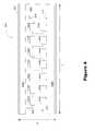
- FIG. 7is a schematic diagram illustrating one possible arrangement of LED groups and LED sets.
- FIG. 8is a schematic diagram of an embodiment of a pass through board that may be used in certain embodiments of the invention.
- LEDs in many LED based lighting systemsmay be limited by thermal management issues and ensuring that enough area remains to facilitate the required interconnections between LEDs where a large number of LEDs are used.
- Certain applicationsmay employ metal core printed circuit boards (MCPCBs) to assist in managing the heat generated by a large number of LEDs.
- MCPCBsmetal core printed circuit boards
- many existing designssuffer from certain shortcomings, including the ability to include a plurality of controllable LEDs in a narrow or small footprint.
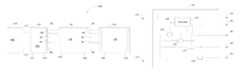
- Light engine 10may be comprised of a substrate 20 , for example, a metal core printed circuit board (PCB) or another suitable thermally conductive substrate, that may have an interconnection layer 22 to facilitate the attachment and interconnection or coupling of various components in a known manner.
- Light engine 10may have a power supply input 50 that may be coupled to the output of a power supply to provide a source of power to light engine 10 .
- Light engine 10may have a plurality of LED sets 30 , 32 , 34 , 36 , 38 , and 40 coupled between power supply input 50 and a power supply return to allow a current to flow from the power supply through the various LED sets.
- Each LED setmay be comprised of a single LED or a plurality of LEDs that may be connected in a number of different configurations.
- each LED setmay have a plurality of LEDs connected in series between power supply input 50 and the power supply return 114 ( FIG. 5 ) as shown in greater detail in FIGS. 3 and 4 .
- LED setsmay also have different number of LEDs, depending on, for example, the forward voltage of the LEDs included in the LED set. The number of LEDs in each LED set may be chosen so that the combined total voltage across each of the LED sets is approximately equal.
- Light engine 10may also have at least one LED group that may be independently controlled by control unit 120 ( FIG. 5 ) in certain embodiments of the invention.
- Each LED groupmay be comprised of at least one LED set.
- the layout of the LED sets in a LED groupmay vary depending on the particular application. For example, the LED sets making up a LED group may be repeated periodically along a length of light engine 10 .
- LED group 150may include LED sets 30 and 38 .
- another LED group(not shown) may include LED sets 32 and 40 .
- the LED sets in a LED groupmay be repeated along a length of light engine 10 periodically depending on the number of LED groups employed in the light engine. For example, for a light engine having a modulo M architecture with M LED groups, each LED group may include every 1/Mth LED set. With reference to FIG. 1 , each LED group may include every fourth LED set as four LED groups (not specifically enumerated) may be employed.
- Each LED groupmay have a return path associated with the LED group to complete the circuit to a power supply return 114 in order to allow a current to flow from power supply output 112 and through the LEDs of each LED group.
- each LED groupmay have a separate return path.
- LED group 150may have LED sets 30 and 38 that may be coupled between power supply input 50 and return path 80 .
- LED sets 32 and 40 of a second LED groupmay be coupled to return path 82 .
- LED sets 34 and 36may be members of different LED groups and be coupled to return paths 84 and 86 respectively.
- LED sets mounted to and coupled together using interconnection layer 22may be coupled to return paths disposed in another interconnection layer, interconnection layer 24 , using layer interconnection elements, such as vias according to known methods.
- LED sets 30 and 38may be coupled to return path 80 using layer interconnection elements 60 and 68 .
- layer interconnection elements 62 , 64 , 66 , and 70may be employed to connect LED sets 32 , 34 , 36 , and 40 to return paths 82 , 84 , 86 , and 82 respectively.
- all LED sets in a particular LED groupmay be coupled to the same return path using layer interconnection elements at various points on light engine 10 .
- Such a configurationallows the LED groups to be controlled independently as described below.
- four return paths and LED groupsare shown in light engine 10 any number of return paths and LED groups may be used, for example, eight LED groups may be used in certain applications.
- LED set 30is shown in greater detail in FIG. 3 . It should be noted that numerous other configurations may also be used without departing from the scope of the invention, including configurations where all LEDs in a LED set are not all coupled together in series.
- a resistor 82may be coupled between power supply input 50 and a plurality of LEDs, for example LEDs 80 a - 80 g , that may be connected in series in layer 22 .
- LED 80 gmay also be coupled to layer interconnection element 60 , which may be coupled to return path 80 in interconnection layer 24 to allow a current to flow from power supply input 50 through LEDs 80 a - 80 g , through return path 80 to power supply return 114 .
- Other LED sets in light engine 10may have the same or different configurations depending on the particular application.
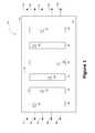
- Light engine 200may have a substrate 202 , which may be a multi-layer metal core printed circuit board, and may have a first interconnection layer 204 .
- Power supply inputs 250 a and 250 bmay be configured to run adjacent to two edges of substrate 202 in layer 204 .
- a plurality of LEDsmay be mounted between power supply inputs 250 a and 250 b in a variety of configurations. For example, LEDs may be mounted in layer 204 in to parallel rows, parallel columns, diagonally, or in another arrangement. LED sets may be constructed by interconnecting LEDs from each row in an alternating pattern along the length of the rows.
- a LED setmay be constructed by coupling resistor 208 to power supply input 250 a , coupling LEDs 206 a - 206 g together in series, coupling LED 206 g to layer interconnection element 210 , and coupling layer interconnection element 210 to a return path (not shown) on another layer (not shown) of substrate 202 .
- another LED setmay be constructed by coupling resistor 212 between power supply input 250 b , coupling resistor 212 to LEDs 216 a - 216 g in series, and coupling LED 216 g to layer interconnection element 214 .
- Layer interconnection element 214may than be connected to a return path (not shown) to complete the circuit.
- Light engine 200may have additional LED sets (not shown) to form a plurality of LED groups.
- the LED sets in each LED groupmay be connected to a separate return path (not shown) associated with each LED group to allow each LED group to be controlled independently.
- power supply inputs 250 a and 250 b and return pathsshould be of a sufficient width to adequately handle the expected current, which may limit the width W of light engine 200 .
- the length L of light engine 200may be at least ten times the width W.
- the traces to implement power supply input 50 and return paths 80 , 82 , 84 , and 86 of light engine 10should be of a sufficient width to accommodate the expected current.
- the width of the power supply input 50 and return paths 80 , 82 , 84 , and 86may limit the dimensions of the light engine and number of LEDs that may be mounted in a particular area.
- Employing a multi-layer metal core PCBmay allow long and narrow light engines to be designed having a large number of LEDs because a second layer may be used for the return paths, allowing more space for power supply inputs and LEDs on a first layer.
- the use of a MCPCBmay allow a greater density of LEDs to be mounted to the light engine because MCPCBs have favourable thermal conduction properties.
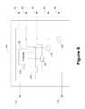
- Lighting apparatus 100may have a power supply 110 having a power supply output 112 and power supply return 114 coupled to control unit 120 .
- Power supply 110may be a constant voltage power supply or alternatively a constant current power supply in certain embodiments.
- Control unit 120may be coupled to light engine 10 using mated connectors 124 of control unit 120 and connector 126 of light engine 10 . The mated connectors may be connected together to allow power supply input 50 , which may be coupled to power supply output 112 to be provided to light engine 10 .
- the connectorsmay be chosen so that they may be physically connected and designed to minimize the space between control unit 120 , light engine 10 , and light engine 310 so that these components provide a more uniform light output and minimize any “dark” spots between light engines and provide a compact footprint for the lighting apparatus.
- Connector 124 of control unit 120may be a female connector adapted to be physically connected with male connector 126 of light engine 10 .
- Connector 128 of light engine 10may be a female connector adapted to be physically connected to male connector 130 of light engine 310 .
- Such an arrangementallows either of light engines 10 or 310 to be physically connected to control unit 120 using connectors 126 or 130 and allows other light engines to be physically connected to light engines 10 or 310 . This may increase the modularity of a lighting apparatus comprising light engines 10 and 310 .
- female connectorsmay be model no. 20-9159-005-101-116 or 22-9159-005-101-116 connectors and male connectors may be model no. 10-9159-005-101-116 connectors from AVX Corporation of South Carolina, U.S.A.
- connectors 124 and 126may couple return paths 80 , 82 , 84 , and 86 between light engine 10 and control unit 10 to provide a conductive path for each return path to power supply return 114 .
- Light engine 10may also have a connector 128 adapted to connect to connector 130 of light engine 310 so that power supply input 50 and return paths 80 , 82 , 84 , and 86 may be coupled between light engines 10 and 310 .
- Light engine 310may also have a connector 132 that may be coupled to another light engine (not shown) in a similar fashion to maintain connectivity of power supply input 50 and return paths 80 , 82 , 84 , and 86 between the various light engines.
- more than three light enginesmay be coupled together in series and controlled by control unit 120 .
- the coupling together of light engines in a modular fashion to be controlled by control unit 120may increase the flexibility and decrease the cost of modifying lighting apparatus 100 for a particular application.
- the modular designmay reduce the number of SKUs of a manufacturer, which may simplify operations and reduce costs.
- Light engines 10 and 310may have the same or different configurations of LED groups and sets. Light engines 10 and 310 may be configured to have the same LED groups coupled to the same return path so that the LED groups on both of light engines 10 and 310 may be simultaneously controlled by control unit 120 . Alternatively, other configurations of LED sets and LED groups may be employed in certain applications, noting that the control unit may be limited to simultaneously controlling LED sets coupled to each separate return path. Although four return paths are shown in FIG. 5 , any other number of return paths may be used, for example, eight return paths may be used in certain applications. In certain embodiments, it may be possible to include four return paths in a light engine having a width of one inch and eight return paths in a light engine having a width of 1.75 inches.
- Control unit 120may be configured to couple power supply output 112 to power supply input 50 of light engine 10 to provide a source of power to light engine 10 and other light engines that may be coupled to light engine 10 .
- Control unit 120may also have a controller 126 connected to switching elements 128 , 132 , 134 , and 136 so that controller 126 may selectively activate and deactivate each switching element to allow a current to flow from power supply output 112 , through light engines 10 and 310 , and back to power supply return 114 .
- switching element 128may be coupled to activation output 130 of controller 126 so that a signal may be provided from controller 126 to selectively activate switching element 128 to allow a current to flow through return path 80 .
- Switching elements 132 , 134 , and 136may be configured in a similar manner to selectively allow current to flow through return paths 82 , 84 , and 86 respectively under the control of controller 126 .
- Switching element 128may be implemented as a NMOS transistor having its gate coupled to activation output 130 , its drain coupled to return path 80 , and its source coupled to power supply return 114 .
- the NMOS transistormay allow a current to flow from drain to source and similarly prevent a current from flowing when activation output is set to low in a known manner.
- Control unit 120may selectively activate all LED sets connected to each return path independently in this configuration. In embodiments where all LED sets in a particular LED group are all connected to the same return path, each LED group may be controlled independently by control unit 120 . This may allow control unit 120 to provide a separate pulse width modulated (PWM) signal to each LED group. The ability to provide a separate PWM signal to each LED group may reduce the load on the power supply as certain algorithms may be used by controller 126 to minimize the current variation by staggering the PWM signal provided to each LED group compared to simultaneously turning on and off all LED groups at once.
- PWMpulse width modulated
- light engine 200may have at least one LED set having a different colour or colour temperature from the remaining LED sets.
- LEDs 206 a - 206 g of a first LED setmay be a first colour
- LEDs 216 a - 216 g of a second LED setmay be a second colour.
- These LED setsmay be included in different LED groups and be controlled separately so that the colour or colour temperature emitted by light engine 200 may be varied by control unit 120 .
- control unit 120may control one LED group so that it has an increased duty cycle to increase the relative intensity of a particular spectrum of light being emitted by light engine 200 .
- the PWM signals applied to each LED groupmay be offset to adjust the light output from light engine 200 .
- At least one LED from at least two different LED groupsmay be mounted on light engine 10 or light engine 200 to be adjacent to or in close proximity to each other. More specifically, at least one LED from at least two different LED groups may be mounted so that the light radiated from these LEDs at least partially overlaps before the emitted light reaches optics (not shown) in a lighting apparatus.
- the lighting apparatusmay also be constructed with particular optics to optimize the mixing of light having different colours or colour temperatures according to methods known in the art. This may allow for a more uniform light output from the lighting apparatus while allowing mixing of the emitted light where all or a subset of LEDs from at least two different LED groups have different colours or colour temperatures. For example, with reference to FIG.
- LED 206 a from a first LED groupmay be mounted adjacent to or in close proximity to LEDs 216 a and 216 b of a second LED group so that the light emitted from LED 206 a at least partially overlaps with the light emitted from LEDs 216 a and 216 b .
- control unit 120may be omitted and replaced with pass through board 160 .
- LED groupsmay not be controlled independently and are simply provided with the signal from power supply output 112 .
- Power supply 110may provide a continuous power output or in certain embodiments be a switching power supply operable to provide a PWM signal.
- Pass through board 160may be coupled to power supply 110 using connector 162 and light engine 10 using connector 164 so that power supply output 112 may be coupled to power supply input 50 of light engine 10 .
- Connector 164may also facilitate the coupling of return paths 80 , 82 , 84 , and 86 from light engine 10 to power supply return 114 via connector 162 .
- Return paths 80 , 82 , 84 , and 86may be coupled together on pass through board 160 so that a single return path is provided to power supply return 114 .
- Pass through board 160may allow a lighting apparatus to be constructed in a modular fashion and allows the same light engine architecture to be used for applications that require a control unit and those that do not require control. This may reduce costs and simplify the manufacturing process.
- a lighting apparatusmay be constructed having the functionality of control unit 120 or pass through board 160 on the same substrate as a light engine.
- a light enginemay or may not be adapted to be coupled together with another light engine and be controlled by the controller mounted to the first light engine.
- This modified architecturemaintains a degree of modular architecture and may simplify the manufacturing process and reduce costs in a similar fashion to that noted above.
- control unit 120located in a remote location or elsewhere in the encasement of a lighting apparatus and connected to at least one light engine via a cable rather than being physically connected to one end of a light engine as shown in FIG. 5 .
- control unit 120may be located below the light engine or elsewhere in certain embodiments of a lighting apparatus.
- the control unitmay continue to be able to control a plurality of light engines that may be coupled together as shown in FIG. 5 in a similar manner.
- Another embodiment of the inventionmay include switching elements that may be controlled by controller 126 , between power supply output 112 and the LED groups of light engine 10 , instead of having the switching elements coupled between the return paths and the power supply return 114 .
- separate power supply inputswould be provided to the LED sets of each LED group and all LED sets may share a common return path or use a plurality of return paths.
- the control unit illustrated in FIG. 6could be modified to use the power supply input 50 as a return path that would be connected to power supply return 114 rather than power supply output 112 .
- return paths 80 , 82 , 84 , and 86may be used as power supply inputs to each LED group and be coupled to power supply output 112 instead of power supply return 114 .
- Switching elementsmay be modified to use PMOS transistors connected between the power supply output 112 and LED groups, with a suitable voltage divider controlled by a transistor coupled to the gate of each PMOS transistor, so that each PMOS transistor may selectively allow a current to flow through each switching elements depending on the output of an activation output of controller 126 in a known manner.
- Such a configuration using a second layer to provide power inputs to each LED groupmay similarly allow a high density of LEDs to be mounted to a light engine.
- control unitmay be utilized provided each LED group may be independently controlled by the control unit without departing from the scope of the invention.
Landscapes
- Engineering & Computer Science (AREA)
- Microelectronics & Electronic Packaging (AREA)
- General Engineering & Computer Science (AREA)
- Power Engineering (AREA)
- Physics & Mathematics (AREA)
- Condensed Matter Physics & Semiconductors (AREA)
- General Physics & Mathematics (AREA)
- Computer Hardware Design (AREA)
- Optics & Photonics (AREA)
- Circuit Arrangement For Electric Light Sources In General (AREA)
- Fastening Of Light Sources Or Lamp Holders (AREA)
- Non-Portable Lighting Devices Or Systems Thereof (AREA)
Abstract
Description
Claims (20)
Priority Applications (7)
| Application Number | Priority Date | Filing Date | Title |
|---|---|---|---|
| US15/136,599US9565727B2 (en) | 2011-03-25 | 2016-04-22 | LED lighting apparatus with first and second colour LEDs |
| US15/426,049US9918362B2 (en) | 2011-03-25 | 2017-02-06 | Control unit and lighting apparatus including light engine and control unit |
| US15/919,147US10251229B2 (en) | 2011-03-25 | 2018-03-12 | Light engine and lighting apparatus with first and second groups of LEDs |
| US16/286,588US10568170B2 (en) | 2011-03-25 | 2019-02-27 | Lighting apparatus with a plurality of light engines |
| US16/792,170US10939527B2 (en) | 2011-03-25 | 2020-02-14 | Light engine configured to be between a power source and another light engine |
| US17/188,582US11653429B2 (en) | 2011-03-25 | 2021-03-01 | Lighting apparatus comprising a light engine with a plurality of interconnection layers |
| US18/190,089US20230380031A1 (en) | 2011-03-25 | 2023-03-26 | Lighting apparatus comprising a light engine with a plurality of interconnection layers |
Applications Claiming Priority (4)
| Application Number | Priority Date | Filing Date | Title |
|---|---|---|---|
| US201161467914P | 2011-03-25 | 2011-03-25 | |
| US13/423,142US8939604B2 (en) | 2011-03-25 | 2012-03-16 | Modular LED strip lighting apparatus |
| US14/606,013US9347631B2 (en) | 2011-03-25 | 2015-01-26 | Modular LED strip lighting apparatus |
| US15/136,599US9565727B2 (en) | 2011-03-25 | 2016-04-22 | LED lighting apparatus with first and second colour LEDs |
Related Parent Applications (1)
| Application Number | Title | Priority Date | Filing Date |
|---|---|---|---|
| US14/606,013ContinuationUS9347631B2 (en) | 2011-03-25 | 2015-01-26 | Modular LED strip lighting apparatus |
Related Child Applications (2)
| Application Number | Title | Priority Date | Filing Date |
|---|---|---|---|
| US14/606,013ContinuationUS9347631B2 (en) | 2011-03-25 | 2015-01-26 | Modular LED strip lighting apparatus |
| US15/426,049ContinuationUS9918362B2 (en) | 2011-03-25 | 2017-02-06 | Control unit and lighting apparatus including light engine and control unit |
Publications (2)
| Publication Number | Publication Date |
|---|---|
| US20160309559A1 US20160309559A1 (en) | 2016-10-20 |
| US9565727B2true US9565727B2 (en) | 2017-02-07 |
Family
ID=47005922
Family Applications (9)
| Application Number | Title | Priority Date | Filing Date |
|---|---|---|---|
| US13/423,142Active2032-08-28US8939604B2 (en) | 2011-03-25 | 2012-03-16 | Modular LED strip lighting apparatus |
| US14/606,013ActiveUS9347631B2 (en) | 2011-03-25 | 2015-01-26 | Modular LED strip lighting apparatus |
| US15/136,599ActiveUS9565727B2 (en) | 2011-03-25 | 2016-04-22 | LED lighting apparatus with first and second colour LEDs |
| US15/426,049ActiveUS9918362B2 (en) | 2011-03-25 | 2017-02-06 | Control unit and lighting apparatus including light engine and control unit |
| US15/919,147ActiveUS10251229B2 (en) | 2011-03-25 | 2018-03-12 | Light engine and lighting apparatus with first and second groups of LEDs |
| US16/286,588ActiveUS10568170B2 (en) | 2011-03-25 | 2019-02-27 | Lighting apparatus with a plurality of light engines |
| US16/792,170ActiveUS10939527B2 (en) | 2011-03-25 | 2020-02-14 | Light engine configured to be between a power source and another light engine |
| US17/188,582Active2032-04-19US11653429B2 (en) | 2011-03-25 | 2021-03-01 | Lighting apparatus comprising a light engine with a plurality of interconnection layers |
| US18/190,089AbandonedUS20230380031A1 (en) | 2011-03-25 | 2023-03-26 | Lighting apparatus comprising a light engine with a plurality of interconnection layers |
Family Applications Before (2)
| Application Number | Title | Priority Date | Filing Date |
|---|---|---|---|
| US13/423,142Active2032-08-28US8939604B2 (en) | 2011-03-25 | 2012-03-16 | Modular LED strip lighting apparatus |
| US14/606,013ActiveUS9347631B2 (en) | 2011-03-25 | 2015-01-26 | Modular LED strip lighting apparatus |
Family Applications After (6)
| Application Number | Title | Priority Date | Filing Date |
|---|---|---|---|
| US15/426,049ActiveUS9918362B2 (en) | 2011-03-25 | 2017-02-06 | Control unit and lighting apparatus including light engine and control unit |
| US15/919,147ActiveUS10251229B2 (en) | 2011-03-25 | 2018-03-12 | Light engine and lighting apparatus with first and second groups of LEDs |
| US16/286,588ActiveUS10568170B2 (en) | 2011-03-25 | 2019-02-27 | Lighting apparatus with a plurality of light engines |
| US16/792,170ActiveUS10939527B2 (en) | 2011-03-25 | 2020-02-14 | Light engine configured to be between a power source and another light engine |
| US17/188,582Active2032-04-19US11653429B2 (en) | 2011-03-25 | 2021-03-01 | Lighting apparatus comprising a light engine with a plurality of interconnection layers |
| US18/190,089AbandonedUS20230380031A1 (en) | 2011-03-25 | 2023-03-26 | Lighting apparatus comprising a light engine with a plurality of interconnection layers |
Country Status (1)
| Country | Link |
|---|---|
| US (9) | US8939604B2 (en) |
Cited By (2)
| Publication number | Priority date | Publication date | Assignee | Title |
|---|---|---|---|---|
| US10251229B2 (en)* | 2011-03-25 | 2019-04-02 | Arkalumen Inc. | Light engine and lighting apparatus with first and second groups of LEDs |
| US10568180B2 (en) | 2015-05-05 | 2020-02-18 | Arkalumen Inc. | Method and apparatus for controlling a lighting module having a plurality of LED groups |
Families Citing this family (18)
| Publication number | Priority date | Publication date | Assignee | Title |
|---|---|---|---|---|
| US9086435B2 (en) | 2011-05-10 | 2015-07-21 | Arkalumen Inc. | Circuits for sensing current levels within a lighting apparatus incorporating a voltage converter |
| US9089024B2 (en) | 2010-05-11 | 2015-07-21 | Arkalumen Inc. | Methods and apparatus for changing a DC supply voltage applied to a lighting circuit |
| US9192009B2 (en) | 2011-02-14 | 2015-11-17 | Arkalumen Inc. | Lighting apparatus and method for detecting reflected light from local objects |
| US8941308B2 (en) | 2011-03-16 | 2015-01-27 | Arkalumen Inc. | Lighting apparatus and methods for controlling lighting apparatus using ambient light levels |
| US9060400B2 (en) | 2011-07-12 | 2015-06-16 | Arkalumen Inc. | Control apparatus incorporating a voltage converter for controlling lighting apparatus |
| US10980121B2 (en)* | 2015-02-16 | 2021-04-13 | Nthdegree Technologies Worldwide Inc. | Printed LED driver circuit |
| US9992829B2 (en) | 2015-05-05 | 2018-06-05 | Arkalumen Inc. | Control apparatus and system for coupling a lighting module to a constant current DC driver |
| US9775211B2 (en) | 2015-05-05 | 2017-09-26 | Arkalumen Inc. | Circuit and apparatus for controlling a constant current DC driver output |
| US9992836B2 (en) | 2015-05-05 | 2018-06-05 | Arkawmen Inc. | Method, system and apparatus for activating a lighting module using a buffer load module |
| US10225904B2 (en) | 2015-05-05 | 2019-03-05 | Arkalumen, Inc. | Method and apparatus for controlling a lighting module based on a constant current level from a power source |
| US10201044B2 (en)* | 2015-10-27 | 2019-02-05 | Abl Ip Holding Llc | Modular light-emitting diode fixtures |
| US10278251B1 (en) | 2018-02-26 | 2019-04-30 | Optic Arts, Inc. | Light device system and method |
| EP3582263B1 (en) | 2018-06-15 | 2023-03-29 | Arnold & Richter Cine Technik GmbH & Co. Betriebs KG | Light generating assembly for a headlight and headlight |
| EP3925415B1 (en)* | 2019-02-12 | 2023-08-16 | Lumileds Holding B.V. | Lighting device and lighting system |
| WO2021001233A1 (en)* | 2019-07-04 | 2021-01-07 | Lumileds Holding B.V. | Lighting device |
| US20240090104A1 (en)* | 2021-01-18 | 2024-03-14 | Signify Holding B.V. | A control system for configuring a plurality of lighting devices of a lighting system and a method thereof |
| CN113507763A (en)* | 2021-07-09 | 2021-10-15 | 漳州立达信光电子科技有限公司 | Color temperature adjusting method and system for LED light source |
| EP4544222A1 (en) | 2022-06-24 | 2025-04-30 | Signify Holding B.V. | Driving apparatus for one or more led arrangements |
Citations (158)
| Publication number | Priority date | Publication date | Assignee | Title |
|---|---|---|---|---|
| US4593234A (en) | 1982-05-11 | 1986-06-03 | Yang Jerry S C | Programmable apparatus for controlling illuminating lamps |
| US5006782A (en) | 1989-06-15 | 1991-04-09 | International Rectifier Corporation | Cascaded buck converter circuit with reduced power loss |
| US5237264A (en) | 1987-07-30 | 1993-08-17 | Lutron Electronics Co., Inc. | Remotely controllable power control system |
| US5248919A (en) | 1992-03-31 | 1993-09-28 | Lutron Electronics Co., Inc. | Lighting control device |
| US5783909A (en) | 1997-01-10 | 1998-07-21 | Relume Corporation | Maintaining LED luminous intensity |
| US5803579A (en) | 1996-06-13 | 1998-09-08 | Gentex Corporation | Illuminator assembly incorporating light emitting diodes |
| US5932995A (en) | 1998-03-03 | 1999-08-03 | Magnetek, Inc. | Dual buck converter with coupled inductors |
| US5949539A (en) | 1997-11-10 | 1999-09-07 | American Iron And Steel Institute | Real-time method and apparatus for measuring the decay-time constant of a fluorescing phosphor |
| US6069905A (en) | 1997-12-31 | 2000-05-30 | Honeywell Inc. | Vertical cavity surface emitting laser having intensity control |
| US6127798A (en) | 1998-04-14 | 2000-10-03 | Lansang; Enrique | Electric power supply having two electrical battery storage means for vehicles and other applications |
| US6150774A (en) | 1997-08-26 | 2000-11-21 | Color Kinetics, Incorporated | Multicolored LED lighting method and apparatus |
| US6175195B1 (en) | 1997-04-10 | 2001-01-16 | Philips Electronics North America Corporation | Triac dimmable compact fluorescent lamp with dimming interface |
| WO2001013038A1 (en) | 1999-08-14 | 2001-02-22 | Kevin Carl Patrick Foulsham | Solar-powered apparatus |
| US6198230B1 (en) | 1998-04-15 | 2001-03-06 | Talking Lights | Dual-use electronic transceiver set for wireless data networks |
| US6222352B1 (en) | 1999-05-06 | 2001-04-24 | Fairchild Semiconductor Corporation | Multiple voltage output buck converter with a single inductor |
| US6307331B1 (en) | 1998-05-18 | 2001-10-23 | Leviton Manufacturing Co., Inc. | Multiple sensor lux reader and averager |
| US6351079B1 (en) | 1999-08-19 | 2002-02-26 | Schott Fibre Optics (Uk) Limited | Lighting control device |
| US6400482B1 (en) | 1998-04-15 | 2002-06-04 | Talking Lights, Llc | Communication system |
| US6426599B1 (en) | 1999-04-14 | 2002-07-30 | Talking Lights, Llc | Dual-use electronic transceiver set for wireless data networks |
| US6441558B1 (en) | 2000-12-07 | 2002-08-27 | Koninklijke Philips Electronics N.V. | White LED luminary light control system |
| US6445139B1 (en) | 1998-12-18 | 2002-09-03 | Koninklijke Philips Electronics N.V. | Led luminaire with electrically adjusted color balance |
| US6495964B1 (en) | 1998-12-18 | 2002-12-17 | Koninklijke Philips Electronics N.V. | LED luminaire with electrically adjusted color balance using photodetector |
| US6504633B1 (en) | 1998-04-15 | 2003-01-07 | Talking Lights | Analog and digital electronic receivers for dual-use wireless data networks |
| US6518561B1 (en) | 1999-11-05 | 2003-02-11 | Sony Corporation | User detection circuit with environmental light detector |
| US6548967B1 (en) | 1997-08-26 | 2003-04-15 | Color Kinetics, Inc. | Universal lighting network methods and systems |
| US6596977B2 (en) | 2001-10-05 | 2003-07-22 | Koninklijke Philips Electronics N.V. | Average light sensing for PWM control of RGB LED based white light luminaries |
| US6621235B2 (en) | 2001-08-03 | 2003-09-16 | Koninklijke Philips Electronics N.V. | Integrated LED driving device with current sharing for multiple LED strings |
| US20040119602A1 (en) | 1999-05-04 | 2004-06-24 | Blum Ronald D. | Floor display system with variable image orientation |
| US6794831B2 (en) | 1998-04-15 | 2004-09-21 | Talking Lights Llc | Non-flickering illumination based communication |
| US6798152B2 (en) | 2002-08-21 | 2004-09-28 | Freescale Semiconductor, Inc. | Closed loop current control circuit and method thereof |
| US20040263093A1 (en) | 2002-06-07 | 2004-12-30 | Yoko Matsubayashi | Electrodeless light bulb type fluorescent lamp and discharge lamp lighting device |
| US6853150B2 (en) | 2001-12-28 | 2005-02-08 | Koninklijke Philips Electronics N.V. | Light emitting diode driver |
| US6894442B1 (en) | 2003-12-18 | 2005-05-17 | Agilent Technologies, Inc. | Luminary control system |
| US20050127888A1 (en) | 2003-12-15 | 2005-06-16 | Dialog Semiconductor Gmbh | Current sensing circuit for DC/DC buck converters |
| US20050156644A1 (en) | 2002-11-14 | 2005-07-21 | Kent Karnahan | Power converter circuitry and method |
| US20050173924A1 (en) | 2004-02-06 | 2005-08-11 | French Michael J. | System and method for charging a battery in a recreational product from an engine driven high voltage charging system |
| US20050199841A1 (en) | 2004-03-09 | 2005-09-15 | O'maley James | Adapter for touch-free operation of gooseneck faucet |
| US20050213353A1 (en) | 2004-03-15 | 2005-09-29 | Color Kinetics Incorporated | LED power control methods and apparatus |
| US20050225264A1 (en) | 2004-03-30 | 2005-10-13 | Kemp William H | LED lamp with color and brightness controller for use in wet, electrically hazardous bathing environments |
| US20050269580A1 (en) | 2004-06-04 | 2005-12-08 | D Angelo Kevin P | Single wire serial protocol for RGB LED drivers |
| US20060044800A1 (en) | 2002-10-31 | 2006-03-02 | Gerd Reime | Device for controlling lighting, more especially inside the passenger compartments of vehicles and control , method therefor |
| US20060049782A1 (en) | 2004-09-08 | 2006-03-09 | Vornsand Steven J | Lighting apparatus having a plurality of independently controlled sources of different colors of light |
| US7016115B1 (en) | 1998-04-15 | 2006-03-21 | Talking Lights, Llc | Communication with non-flickering illumination |
| US20060113975A1 (en) | 2004-11-29 | 2006-06-01 | Supertex, Inc. | Method and apparatus for controlling output current of a cascaded DC/DC converter |
| US20060239689A1 (en) | 2005-01-25 | 2006-10-26 | Tir Systems, Ltd. | Method and apparatus for illumination and communication |
| US7141779B1 (en) | 2005-09-19 | 2006-11-28 | Avago Technologies Ecbu Ip (Singapore) Pte. Ltd. | System and method for emitting and detecting light using light emitting diode |
| US20070080911A1 (en) | 2005-10-11 | 2007-04-12 | Da Liu | Controller circuitry for light emitting diodes |
| US20070103086A1 (en) | 2005-11-10 | 2007-05-10 | Neudorf Jason Christopher J | Modulation method and apparatus for dimming and/or colour mixing utilizing leds |
| US20070103832A1 (en) | 2005-11-08 | 2007-05-10 | Yazaki Corporation | Load driving device |
| US20070159421A1 (en) | 2006-01-10 | 2007-07-12 | Powerdsine, Ltd. | Secondary Side Post Regulation for LED Backlighting |
| US20070182338A1 (en) | 2006-01-20 | 2007-08-09 | Exclara Inc. | Current regulator for modulating brightness levels of solid state lighting |
| US20070195552A1 (en) | 2006-02-21 | 2007-08-23 | Lg Innotek Co., Ltd | Apparatus and method for controlling operation of LED in light unit |
| US7265681B2 (en) | 2004-11-19 | 2007-09-04 | Quanta Computer Inc. | Light emitted diode driving apparatus |
| US20070229047A1 (en) | 2006-03-31 | 2007-10-04 | James Sigamani | Tapped inductor buck dc-dc converter |
| US20070268028A1 (en) | 2005-07-11 | 2007-11-22 | Moyer Vincent C | Current fault detection for light emitters |
| US20070267978A1 (en) | 2006-05-22 | 2007-11-22 | Exclara Inc. | Digitally controlled current regulator for high power solid state lighting |
| US20070278974A1 (en) | 2006-05-31 | 2007-12-06 | Led Lighting Fixtures, Inc. | Lighting device with color control, and method of lighting |
| US7321203B2 (en) | 2006-03-13 | 2008-01-22 | Linear Technology Corporation | LED dimming control technique for increasing the maximum PWM dimming ratio and avoiding LED flicker |
| US7352135B2 (en) | 2005-11-04 | 2008-04-01 | Koito Manufacturing Co., Ltd. | Lighting controller for lighting device for vehicle |
| US20080079705A1 (en) | 2006-09-28 | 2008-04-03 | Chien-Yi Yang | LIGHT SOURCE SYSTEM WITH LEDs AND DRIVING METHOD THEREOF |
| US20080088769A1 (en) | 2006-10-17 | 2008-04-17 | Samsung Electronics Co., Ltd., | Backlight, backlight assembly, liquid crystal display having the same and method thereof |
| US20080138085A1 (en) | 2006-06-29 | 2008-06-12 | Formolight Technologies Inc. | Illumination with optical communication method |
| US20080150449A1 (en) | 2006-12-26 | 2008-06-26 | Beyond Innovation Technology Co., Ltd. | Control circuits for dimming control |
| US20080180040A1 (en) | 2007-01-30 | 2008-07-31 | Cypress Semiconductor Corporation | Method and apparatus for networked illumination devices |
| US20080191642A1 (en) | 2005-04-08 | 2008-08-14 | Wart Hog Ii Holding B.V. | Methods and Apparatus for Operating Groups of High-Power Leds |
| US20080224636A1 (en) | 2007-03-12 | 2008-09-18 | Melanson John L | Power control system for current regulated light sources |
| US20080238341A1 (en) | 2007-03-29 | 2008-10-02 | Microsemi Corp. - Analog Mixed Signal Group Ltd. | Color Control for Dynamic Scanning Backlight |
| US20080252664A1 (en) | 2007-04-11 | 2008-10-16 | Zhi-Xian Huang | Device and Method for Driving Light-Emitting Diodes |
| US20080272277A1 (en) | 2007-05-02 | 2008-11-06 | Novatek Microelectronics Corp. | Apparatus and method for controlling brightness of light source and displaying apparatus |
| US20090027652A1 (en) | 2007-07-25 | 2009-01-29 | Tom Chang | Integrated ambient light sensor and distance sensor |
| US7486032B2 (en) | 2006-04-07 | 2009-02-03 | Samsung Electro-Mechanics Co., Ltd. | Apparatus for driving LED arrays |
| US7495425B2 (en) | 2005-01-18 | 2009-02-24 | Puls Gmbh | Buck converter with demagnetization detection of the inductor |
| US7498754B2 (en) | 2007-04-02 | 2009-03-03 | Supertex, Inc. | Architecture for driving multiple loads at constant current |
| US7511463B2 (en) | 2005-06-21 | 2009-03-31 | Intel Corporation | Multiple output buck converter |
| US20090096392A1 (en) | 2006-03-21 | 2009-04-16 | Nxp B.V. | Pulse width modulation based led dimmer control |
| US20090134817A1 (en) | 2005-12-20 | 2009-05-28 | Tir Technology Lp | Method and Apparatus for Controlling Current Supplied to Electronic Devices |
| US20090160422A1 (en) | 2007-12-20 | 2009-06-25 | Microsemi Corporation | Boost converter with adaptive coil peak current |
| US20090167194A1 (en) | 2007-12-28 | 2009-07-02 | Minoru Mizuta | Light emission control system and image display system |
| US20090174337A1 (en) | 2007-10-06 | 2009-07-09 | Lynk Labs, Inc. | LED circuits and assemblies |
| US20090195168A1 (en) | 2008-02-05 | 2009-08-06 | Intersil Americas Inc. | Method and system for dimming ac-powered light emitting diode (led) lighting systems using conventional incandescent dimmers |
| US20090195183A1 (en) | 2008-02-05 | 2009-08-06 | Ta-Yung Yang | Controller of led lighting to control the maximum voltage of leds and the maximum voltage across current sources |
| US20090251059A1 (en) | 2008-04-04 | 2009-10-08 | Lemnis Lighting Patent Holding B.V. | Dimmer triggering circuit, dimmer system and dimmable device |
| US20090251071A1 (en) | 2008-04-08 | 2009-10-08 | Micrel, Inc. | Driving Multiple Parallel LEDs with Reduced Power Supply Ripple |
| US7633577B2 (en) | 2004-10-30 | 2009-12-15 | Lg Display Co., Ltd. | Light emitting diode backlight unit and liquid crystal display device using the same |
| US20090322252A1 (en) | 2008-06-30 | 2009-12-31 | Green Solution Technology Inc. | Led driving circuit and a mosfet switch module thereof |
| US7649326B2 (en) | 2006-03-27 | 2010-01-19 | Texas Instruments Incorporated | Highly efficient series string LED driver with individual LED control |
| US20100019692A1 (en) | 2008-07-25 | 2010-01-28 | Sanken Electric Co., Ltd. | Power conversion apparatus |
| US20100033150A1 (en) | 2008-08-07 | 2010-02-11 | Asic Advantage Inc. | Bus voltage optimizer for switched power converter |
| US20100033146A1 (en) | 2008-08-07 | 2010-02-11 | Asic Advantage Inc. | Current sensing for high voltage buck converter |
| US20100046210A1 (en) | 2008-08-19 | 2010-02-25 | Plextronics, Inc. | Organic light emitting diode products |
| US20100060187A1 (en) | 2008-09-05 | 2010-03-11 | Lutron Electronics Co., Inc. | Hybrid light source |
| US20100066484A1 (en) | 2008-09-15 | 2010-03-18 | Commtiva Technology Corporation | Remote monitor/control for billboard lighting or standby power system |
| US20100066266A1 (en) | 2008-09-18 | 2010-03-18 | Richtek Technology Corporation | Led bulb, light emitting device control method, and light emitting device controller circuit with dimming function adjustable by AC signal |
| US7683470B2 (en) | 2006-02-22 | 2010-03-23 | Samsung Electro-Mechanics Co., Ltd. | LED package |
| US7683504B2 (en) | 2006-09-13 | 2010-03-23 | Lutron Electronics Co., Inc. | Multiple location electronic timer system |
| US20100072902A1 (en) | 2006-10-06 | 2010-03-25 | Koninklijke Philips Electronics N.V. | Light element array with controllable current sources and method of operation |
| US20100072899A1 (en) | 2007-10-22 | 2010-03-25 | Engstrand Bradley W | System and/or method for reading, measuring and/or controlling intensity of light emitted from an LED |
| US20100079124A1 (en) | 2008-09-30 | 2010-04-01 | John Laurence Melanson | Adjustable Constant Current Source with Continuous Conduction Mode ("CCM") and Discontinuous Conduction Mode ("DCM") Operation |
| US20100100253A1 (en) | 2008-04-17 | 2010-04-22 | Demi Energy, Inc. | Systems and Methods for Controlling Energy Consumption |
| US20100102230A1 (en) | 2008-10-22 | 2010-04-29 | Tom Chang | Light detection circuit for ambient light and proximity sensor |
| US20100117450A1 (en) | 2008-09-05 | 2010-05-13 | Firas Azrai | Integrated multiple output power conversion system |
| US20100156319A1 (en) | 2008-08-29 | 2010-06-24 | John Laurence Melanson | LED Lighting System with Accurate Current Control |
| US20100164406A1 (en) | 2008-07-25 | 2010-07-01 | Kost Michael A | Switching power converter control with triac-based leading edge dimmer compatibility |
| US7750616B2 (en) | 2007-06-21 | 2010-07-06 | Green Mark Technology Inc. | Buck converter LED driver circuit |
| US20100171442A1 (en) | 2008-12-12 | 2010-07-08 | Draper William A | Light Emitting Diode Based Lighting System With Time Division Ambient Light Feedback Response |
| US20100171429A1 (en) | 2009-01-07 | 2010-07-08 | Richard Jeff Garcia | Method of LED dimming using ambient light feedback |
| US20100177127A1 (en) | 2009-01-09 | 2010-07-15 | Renesas Technology Corp., | Led driving circuit, semiconductor element and image display device |
| US7759881B1 (en) | 2008-03-31 | 2010-07-20 | Cirrus Logic, Inc. | LED lighting system with a multiple mode current control dimming strategy |
| US20100194308A1 (en) | 2009-01-30 | 2010-08-05 | Freescale Semiconductor, Inc. | Led driver with dynamic headroom control |
| US20100245289A1 (en) | 2009-03-31 | 2010-09-30 | Miroslav Svajda | Apparatus and method for optical proximity sensing and touch input control |
| US20100264834A1 (en) | 2007-12-07 | 2010-10-21 | Koninklijke Philips Electronics N.V. | Led lamp color control system and method |
| US20100277075A1 (en) | 2009-04-29 | 2010-11-04 | Intersil Americas Inc. | Long range proximity and/or motion detector with ambient light detection capabilities |
| US20100289424A1 (en) | 2008-11-17 | 2010-11-18 | Lepower Semiconductor Inc. | Methods and Circuits for LED Drivers and for PWM Dimming Controls |
| US20100302477A1 (en) | 2009-05-26 | 2010-12-02 | Sony Corporation | Optical element, illumination device and display device |
| US20100320936A1 (en) | 2009-06-19 | 2010-12-23 | Kaiwei Yao | High-voltage led drive scheme with partial power regulation |
| US20100320939A1 (en) | 2009-06-19 | 2010-12-23 | Hon Hai Precision Industry Co., Ltd. | Light emitting diode illuminating system and controlling method thereof |
| US20110006691A1 (en) | 2009-07-10 | 2011-01-13 | Stmicroelectronics Design And Application S.R.O. | Voltage converter for supplying a semiconductor light source, in particular a led lamp |
| US20110050130A1 (en) | 2008-01-17 | 2011-03-03 | Osram Gesellschaft Mit Beschraenkter Haftung | Buck converter and method for providing a current for at least one led |
| US20110068703A1 (en) | 2009-09-18 | 2011-03-24 | Boca Flasher, Inc. | 90-260Vac Dimmable MR16 LED Lamp |
| US20110086676A1 (en) | 2008-03-24 | 2011-04-14 | Nanolambda, Inc. | Multi-purpose plasmonic ambient light sensor and visual range proximity sensor |
| US20110101950A1 (en) | 2008-05-28 | 2011-05-05 | Babb Samuel M | Impedance correction |
| US20110115394A1 (en) | 2007-09-21 | 2011-05-19 | Exclara Inc. | System and Method for Regulation of Solid State Lighting |
| US20110115412A1 (en) | 2008-07-11 | 2011-05-19 | Eldolab Holding B.V. | Power converter for an led assembly and lighting application |
| US20110187313A1 (en) | 2010-01-29 | 2011-08-04 | Samsung Electronics Co. Ltd. | Apparatus and method for displaying capacity and charge/discharge state of battery in portable device |
| US20110194047A1 (en) | 2008-10-09 | 2011-08-11 | Koninklijke Philips Electronics N.V. | Display device, method of controlling a light emitting diode array of the display device, and computer program product |
| US20110193489A1 (en) | 2008-10-10 | 2011-08-11 | Koninklijke Philips Electronics N.V. | Methods and apparatus for controlling multiple light sources via a single regulator circuit to provide variable color and/or color temperature light |
| US20110227492A1 (en) | 2010-03-16 | 2011-09-22 | Lei Du | Driver systems for driving light emitting diodes and associated driving methods |
| US20110279053A1 (en) | 2010-05-11 | 2011-11-17 | Arkalumen Inc. | Variable voltage control apparatus and lighting apparatus incorporating control apparatus |
| US20110279040A1 (en) | 2010-05-11 | 2011-11-17 | Arkalumen Inc. | Methods and apparatus for changing a dc supply voltage applied to a lighting circuit |
| US20110279048A1 (en) | 2010-05-11 | 2011-11-17 | Arkalumen Inc. | Circuits for sensing current levels within lighting apparatus |
| US20110298386A1 (en) | 2010-04-09 | 2011-12-08 | Artemide S.P.A. | Led lighting fixture with one set of intensity of light |
| US8193737B2 (en) | 2008-06-10 | 2012-06-05 | Microsemi Corp. -Analog Mixed Signal Group Ltd. | Color manager for backlight systems operative at multiple current levels |
| US20120146519A1 (en) | 2010-12-13 | 2012-06-14 | Arkalumen Inc. | Lighting apparatus and circuits for lighting apparatus |
| US8232742B2 (en) | 2008-11-27 | 2012-07-31 | Arkalumen Inc. | Method, apparatus and computer-readable media for controlling lighting devices |
| US8248439B2 (en) | 2008-03-07 | 2012-08-21 | O2Micro, Inc | Backlight controller for driving light sources |
| US8247975B2 (en) | 2009-02-03 | 2012-08-21 | Lg Display Co., Ltd. | Backlight assembly for liquid crystal display device |
| US20120262071A1 (en) | 2011-02-14 | 2012-10-18 | Arkalumen Inc. | Lighting apparatus and method for detecting reflected light from local objects |
| US20120262076A1 (en) | 2011-03-25 | 2012-10-18 | Arkalumen Inc. | Modular led strip lighting apparatus |
| US20120268019A1 (en) | 2011-03-16 | 2012-10-25 | Arkalumen Inc. | Lighting apparatus and methods for controlling lighting apparatus using ambient light levels |
| US8324834B2 (en) | 2009-10-16 | 2012-12-04 | Green Solution Technology Co., Ltd. | Load driving circuit and multi-load feedback circuit |
| US20120312956A1 (en) | 2011-06-11 | 2012-12-13 | Tom Chang | Light sensor system for object detection and gesture recognition, and object detection method |
| US20120320626A1 (en) | 2011-06-14 | 2012-12-20 | Osram Sylvania Inc. | Edge-lit light fixture incorporating a downlight and having a uniform external appearance |
| US20130009561A1 (en) | 2011-05-10 | 2013-01-10 | Arkalumen Inc. | Circuits for sensing current levels within a lighting apparatus incorporating a voltage converter |
| US20130015774A1 (en) | 2011-07-12 | 2013-01-17 | Arkalumen Inc. | Control apparatus incorporating a voltage converter for controlling lighting apparatus |
| US8358085B2 (en) | 2009-01-13 | 2013-01-22 | Terralux, Inc. | Method and device for remote sensing and control of LED lights |
| US20130223058A1 (en) | 2011-11-11 | 2013-08-29 | Arkalumen Inc. | Apparatus and system for emitting light using a grid light engine |
| US20130278139A1 (en)* | 2012-04-20 | 2013-10-24 | 4S Industries, Inc. d/b/a Bulldog-Lighting | System and Apparatus for a Dual LED Light Bar |
| US20130297251A1 (en) | 2012-05-04 | 2013-11-07 | Abl Ip Holding, Llc | System and Method For Determining High Resolution Positional Data From Limited Number of Analog Inputs |
| US20130293722A1 (en) | 2012-05-07 | 2013-11-07 | Chia Ming Chen | Light control systems and methods |
| US20130301266A1 (en)* | 2009-07-24 | 2013-11-14 | Remote Ocean Systems, Inc. | Modular lamp for illuminating a hazardous underwater environment |
| US20130300316A1 (en) | 2012-05-04 | 2013-11-14 | Abl Ip Holding, Llc | Gestural control dimmer switch |
| US8587203B2 (en) | 2011-06-09 | 2013-11-19 | Osram Sylvania Inc. | Multiple channel light source power supply with output protection |
| US8681192B2 (en) | 2011-01-12 | 2014-03-25 | Sharp Kabushiki Kaisha | Sensor device and electronic apparatus |
| US8766162B2 (en) | 2012-01-12 | 2014-07-01 | Maxim Integrated Products, Inc. | Ambient light based gesture detection |
| US8848202B2 (en) | 2011-11-11 | 2014-09-30 | Intersil Americas LLC | Optical proximity sensors with offset compensation |
| US20140292214A1 (en)* | 2013-03-26 | 2014-10-02 | Michelle Kun Huang | Interconnectable LED Module for Use in a Direct Current Circuit |
| US9204511B2 (en) | 2012-10-10 | 2015-12-01 | Panasonic Intellectual Property Management Co., Ltd. | Lighting apparatus and lighting fixture using same |
| US20160212804A1 (en)* | 2013-06-20 | 2016-07-21 | Koninklijke Philips N.V. | Lighting device comprising at least two sets of LEDs |
Family Cites Families (26)
| Publication number | Priority date | Publication date | Assignee | Title |
|---|---|---|---|---|
| US6175105B1 (en) | 1998-10-02 | 2001-01-16 | Bestfoods | Container for microwave cooking of food products containing liquids |
| US7521667B2 (en)* | 2003-06-23 | 2009-04-21 | Advanced Optical Technologies, Llc | Intelligent solid state lighting |
| EP1825717B1 (en)* | 2004-11-23 | 2014-01-08 | Koninklijke Philips N.V. | Apparatus and method for controlling colour and colour temperature of light generated by a digitally controlled luminaire |
| US7347706B1 (en)* | 2005-07-21 | 2008-03-25 | Leotek Electronics Corporation | Light emitting diode (LED) based street light and other lighting applications |
| CN101292574B (en) | 2005-08-17 | 2012-12-26 | 皇家飞利浦电子股份有限公司 | Digitally controlled luminaire system |
| US20080164826A1 (en) | 2007-01-05 | 2008-07-10 | Color Kinetics Incorporated | Methods and apparatus for simulating resistive loads |
| US8552659B2 (en) | 2007-08-07 | 2013-10-08 | Koninklijke Philips N.V. | Method and apparatus for discriminating modulated light in a mixed light system |
| US8400071B2 (en) | 2007-12-07 | 2013-03-19 | Koninklijke Philips Electronics N.V. | LED lamp power management system and method |
| US7952294B2 (en) | 2008-04-06 | 2011-05-31 | Exclara, Inc. | Apparatus, system and method for cascaded power conversion |
| CN201220626Y (en) | 2008-04-28 | 2009-04-15 | 上海晨阑光电器件有限公司 | PWM type lighteness adjustable module group for LED automobile tail lamp |
| CN201188301Y (en)* | 2008-04-29 | 2009-01-28 | 李金传 | Arbitrarily expandable LED display module |
| CN101614329A (en)* | 2008-06-27 | 2009-12-30 | 富准精密工业(深圳)有限公司 | Led lamp and photo engine thereof |
| US8344638B2 (en) | 2008-07-29 | 2013-01-01 | Point Somee Limited Liability Company | Apparatus, system and method for cascaded power conversion |
| TWI495389B (en) | 2008-09-05 | 2015-08-01 | Eldolab Holding Bv | Led based lighting application |
| EP2352392B1 (en) | 2008-10-20 | 2016-08-03 | DSM IP Assets B.V. | Fish flavour |
| US9351365B2 (en) | 2009-08-18 | 2016-05-24 | Eldolab Holding B.V. | Control unit for LED assembly and lighting system |
| US8466628B2 (en) | 2009-10-07 | 2013-06-18 | Lutron Electronics Co., Inc. | Closed-loop load control circuit having a wide output range |
| US8988050B2 (en) | 2009-11-25 | 2015-03-24 | Lutron Electronics Co., Inc. | Load control device for high-efficiency loads |
| US8456095B2 (en) | 2010-03-19 | 2013-06-04 | Active-Semi, Inc. | Reduced flicker AC LED lamp with separately shortable sections of an LED string |
| US8314566B2 (en)* | 2011-02-22 | 2012-11-20 | Quarkstar Llc | Solid state lamp using light emitting strips |
| US9609709B2 (en)* | 2012-08-21 | 2017-03-28 | Cree, Inc. | Multi-segment LED components and LED lighting apparatus including the same |
| US9111464B2 (en)* | 2013-06-18 | 2015-08-18 | LuxVue Technology Corporation | LED display with wavelength conversion layer |
| US10225904B2 (en) | 2015-05-05 | 2019-03-05 | Arkalumen, Inc. | Method and apparatus for controlling a lighting module based on a constant current level from a power source |
| US9992836B2 (en) | 2015-05-05 | 2018-06-05 | Arkawmen Inc. | Method, system and apparatus for activating a lighting module using a buffer load module |
| US9992829B2 (en) | 2015-05-05 | 2018-06-05 | Arkalumen Inc. | Control apparatus and system for coupling a lighting module to a constant current DC driver |
| US9974125B2 (en)* | 2015-07-17 | 2018-05-15 | Cooper Technologies Company | Modular integrated lighting circuit |
- 2012
- 2012-03-16USUS13/423,142patent/US8939604B2/enactiveActive
- 2015
- 2015-01-26USUS14/606,013patent/US9347631B2/enactiveActive
- 2016
- 2016-04-22USUS15/136,599patent/US9565727B2/enactiveActive
- 2017
- 2017-02-06USUS15/426,049patent/US9918362B2/enactiveActive
- 2018
- 2018-03-12USUS15/919,147patent/US10251229B2/enactiveActive
- 2019
- 2019-02-27USUS16/286,588patent/US10568170B2/enactiveActive
- 2020
- 2020-02-14USUS16/792,170patent/US10939527B2/enactiveActive
- 2021
- 2021-03-01USUS17/188,582patent/US11653429B2/enactiveActive
- 2023
- 2023-03-26USUS18/190,089patent/US20230380031A1/ennot_activeAbandoned
Patent Citations (171)
| Publication number | Priority date | Publication date | Assignee | Title |
|---|---|---|---|---|
| US4593234A (en) | 1982-05-11 | 1986-06-03 | Yang Jerry S C | Programmable apparatus for controlling illuminating lamps |
| US5237264A (en) | 1987-07-30 | 1993-08-17 | Lutron Electronics Co., Inc. | Remotely controllable power control system |
| US5006782A (en) | 1989-06-15 | 1991-04-09 | International Rectifier Corporation | Cascaded buck converter circuit with reduced power loss |
| US5248919A (en) | 1992-03-31 | 1993-09-28 | Lutron Electronics Co., Inc. | Lighting control device |
| US5803579A (en) | 1996-06-13 | 1998-09-08 | Gentex Corporation | Illuminator assembly incorporating light emitting diodes |
| US5783909A (en) | 1997-01-10 | 1998-07-21 | Relume Corporation | Maintaining LED luminous intensity |
| US6175195B1 (en) | 1997-04-10 | 2001-01-16 | Philips Electronics North America Corporation | Triac dimmable compact fluorescent lamp with dimming interface |
| US6150774A (en) | 1997-08-26 | 2000-11-21 | Color Kinetics, Incorporated | Multicolored LED lighting method and apparatus |
| US6548967B1 (en) | 1997-08-26 | 2003-04-15 | Color Kinetics, Inc. | Universal lighting network methods and systems |
| US5949539A (en) | 1997-11-10 | 1999-09-07 | American Iron And Steel Institute | Real-time method and apparatus for measuring the decay-time constant of a fluorescing phosphor |
| US6069905A (en) | 1997-12-31 | 2000-05-30 | Honeywell Inc. | Vertical cavity surface emitting laser having intensity control |
| US5932995A (en) | 1998-03-03 | 1999-08-03 | Magnetek, Inc. | Dual buck converter with coupled inductors |
| US6127798A (en) | 1998-04-14 | 2000-10-03 | Lansang; Enrique | Electric power supply having two electrical battery storage means for vehicles and other applications |
| US6954591B2 (en) | 1998-04-15 | 2005-10-11 | Lupton Elmer C | Non-visible communication systems |
| US6794831B2 (en) | 1998-04-15 | 2004-09-21 | Talking Lights Llc | Non-flickering illumination based communication |
| US6198230B1 (en) | 1998-04-15 | 2001-03-06 | Talking Lights | Dual-use electronic transceiver set for wireless data networks |
| US7016115B1 (en) | 1998-04-15 | 2006-03-21 | Talking Lights, Llc | Communication with non-flickering illumination |
| US6400482B1 (en) | 1998-04-15 | 2002-06-04 | Talking Lights, Llc | Communication system |
| US6504633B1 (en) | 1998-04-15 | 2003-01-07 | Talking Lights | Analog and digital electronic receivers for dual-use wireless data networks |
| US6307331B1 (en) | 1998-05-18 | 2001-10-23 | Leviton Manufacturing Co., Inc. | Multiple sensor lux reader and averager |
| US6495964B1 (en) | 1998-12-18 | 2002-12-17 | Koninklijke Philips Electronics N.V. | LED luminaire with electrically adjusted color balance using photodetector |
| US6445139B1 (en) | 1998-12-18 | 2002-09-03 | Koninklijke Philips Electronics N.V. | Led luminaire with electrically adjusted color balance |
| US6426599B1 (en) | 1999-04-14 | 2002-07-30 | Talking Lights, Llc | Dual-use electronic transceiver set for wireless data networks |
| US20040119602A1 (en) | 1999-05-04 | 2004-06-24 | Blum Ronald D. | Floor display system with variable image orientation |
| US6222352B1 (en) | 1999-05-06 | 2001-04-24 | Fairchild Semiconductor Corporation | Multiple voltage output buck converter with a single inductor |
| WO2001013038A1 (en) | 1999-08-14 | 2001-02-22 | Kevin Carl Patrick Foulsham | Solar-powered apparatus |
| US6351079B1 (en) | 1999-08-19 | 2002-02-26 | Schott Fibre Optics (Uk) Limited | Lighting control device |
| US6518561B1 (en) | 1999-11-05 | 2003-02-11 | Sony Corporation | User detection circuit with environmental light detector |
| US6441558B1 (en) | 2000-12-07 | 2002-08-27 | Koninklijke Philips Electronics N.V. | White LED luminary light control system |
| US6621235B2 (en) | 2001-08-03 | 2003-09-16 | Koninklijke Philips Electronics N.V. | Integrated LED driving device with current sharing for multiple LED strings |
| US6596977B2 (en) | 2001-10-05 | 2003-07-22 | Koninklijke Philips Electronics N.V. | Average light sensing for PWM control of RGB LED based white light luminaries |
| US6853150B2 (en) | 2001-12-28 | 2005-02-08 | Koninklijke Philips Electronics N.V. | Light emitting diode driver |
| US20040263093A1 (en) | 2002-06-07 | 2004-12-30 | Yoko Matsubayashi | Electrodeless light bulb type fluorescent lamp and discharge lamp lighting device |
| US6798152B2 (en) | 2002-08-21 | 2004-09-28 | Freescale Semiconductor, Inc. | Closed loop current control circuit and method thereof |
| US20060044800A1 (en) | 2002-10-31 | 2006-03-02 | Gerd Reime | Device for controlling lighting, more especially inside the passenger compartments of vehicles and control , method therefor |
| US20050156644A1 (en) | 2002-11-14 | 2005-07-21 | Kent Karnahan | Power converter circuitry and method |
| US20050127888A1 (en) | 2003-12-15 | 2005-06-16 | Dialog Semiconductor Gmbh | Current sensing circuit for DC/DC buck converters |
| US6894442B1 (en) | 2003-12-18 | 2005-05-17 | Agilent Technologies, Inc. | Luminary control system |
| US20050173924A1 (en) | 2004-02-06 | 2005-08-11 | French Michael J. | System and method for charging a battery in a recreational product from an engine driven high voltage charging system |
| US20050199841A1 (en) | 2004-03-09 | 2005-09-15 | O'maley James | Adapter for touch-free operation of gooseneck faucet |
| US20050213353A1 (en) | 2004-03-15 | 2005-09-29 | Color Kinetics Incorporated | LED power control methods and apparatus |
| US7256554B2 (en) | 2004-03-15 | 2007-08-14 | Color Kinetics Incorporated | LED power control methods and apparatus |
| US7233115B2 (en) | 2004-03-15 | 2007-06-19 | Color Kinetics Incorporated | LED-based lighting network power control methods and apparatus |
| US20050225264A1 (en) | 2004-03-30 | 2005-10-13 | Kemp William H | LED lamp with color and brightness controller for use in wet, electrically hazardous bathing environments |
| US20050269580A1 (en) | 2004-06-04 | 2005-12-08 | D Angelo Kevin P | Single wire serial protocol for RGB LED drivers |
| US20060049782A1 (en) | 2004-09-08 | 2006-03-09 | Vornsand Steven J | Lighting apparatus having a plurality of independently controlled sources of different colors of light |
| US7633577B2 (en) | 2004-10-30 | 2009-12-15 | Lg Display Co., Ltd. | Light emitting diode backlight unit and liquid crystal display device using the same |
| US7265681B2 (en) | 2004-11-19 | 2007-09-04 | Quanta Computer Inc. | Light emitted diode driving apparatus |
| US20060113975A1 (en) | 2004-11-29 | 2006-06-01 | Supertex, Inc. | Method and apparatus for controlling output current of a cascaded DC/DC converter |
| US7495425B2 (en) | 2005-01-18 | 2009-02-24 | Puls Gmbh | Buck converter with demagnetization detection of the inductor |
| US20060239689A1 (en) | 2005-01-25 | 2006-10-26 | Tir Systems, Ltd. | Method and apparatus for illumination and communication |
| US20080191642A1 (en) | 2005-04-08 | 2008-08-14 | Wart Hog Ii Holding B.V. | Methods and Apparatus for Operating Groups of High-Power Leds |
| US7511463B2 (en) | 2005-06-21 | 2009-03-31 | Intel Corporation | Multiple output buck converter |
| US20070268028A1 (en) | 2005-07-11 | 2007-11-22 | Moyer Vincent C | Current fault detection for light emitters |
| US7141779B1 (en) | 2005-09-19 | 2006-11-28 | Avago Technologies Ecbu Ip (Singapore) Pte. Ltd. | System and method for emitting and detecting light using light emitting diode |
| US7847783B2 (en) | 2005-10-11 | 2010-12-07 | O2Micro International Limited | Controller circuitry for light emitting diodes |
| US20070080911A1 (en) | 2005-10-11 | 2007-04-12 | Da Liu | Controller circuitry for light emitting diodes |
| US7352135B2 (en) | 2005-11-04 | 2008-04-01 | Koito Manufacturing Co., Ltd. | Lighting controller for lighting device for vehicle |
| US20070103832A1 (en) | 2005-11-08 | 2007-05-10 | Yazaki Corporation | Load driving device |
| US7457089B2 (en) | 2005-11-08 | 2008-11-25 | Yazaki Corporation | Load driving device with diagnosing unit for overcurrent detector |
| US20070103086A1 (en) | 2005-11-10 | 2007-05-10 | Neudorf Jason Christopher J | Modulation method and apparatus for dimming and/or colour mixing utilizing leds |
| US20090134817A1 (en) | 2005-12-20 | 2009-05-28 | Tir Technology Lp | Method and Apparatus for Controlling Current Supplied to Electronic Devices |
| US20070159421A1 (en) | 2006-01-10 | 2007-07-12 | Powerdsine, Ltd. | Secondary Side Post Regulation for LED Backlighting |
| US20070182338A1 (en) | 2006-01-20 | 2007-08-09 | Exclara Inc. | Current regulator for modulating brightness levels of solid state lighting |
| US20070195552A1 (en) | 2006-02-21 | 2007-08-23 | Lg Innotek Co., Ltd | Apparatus and method for controlling operation of LED in light unit |
| US8105854B2 (en) | 2006-02-22 | 2012-01-31 | Samsung Led Co., Ltd. | LED package |
| US7683470B2 (en) | 2006-02-22 | 2010-03-23 | Samsung Electro-Mechanics Co., Ltd. | LED package |
| US7321203B2 (en) | 2006-03-13 | 2008-01-22 | Linear Technology Corporation | LED dimming control technique for increasing the maximum PWM dimming ratio and avoiding LED flicker |
| US20090096392A1 (en) | 2006-03-21 | 2009-04-16 | Nxp B.V. | Pulse width modulation based led dimmer control |
| US7649326B2 (en) | 2006-03-27 | 2010-01-19 | Texas Instruments Incorporated | Highly efficient series string LED driver with individual LED control |
| US20070229047A1 (en) | 2006-03-31 | 2007-10-04 | James Sigamani | Tapped inductor buck dc-dc converter |
| US7486032B2 (en) | 2006-04-07 | 2009-02-03 | Samsung Electro-Mechanics Co., Ltd. | Apparatus for driving LED arrays |
| US20070267978A1 (en) | 2006-05-22 | 2007-11-22 | Exclara Inc. | Digitally controlled current regulator for high power solid state lighting |
| US20070278974A1 (en) | 2006-05-31 | 2007-12-06 | Led Lighting Fixtures, Inc. | Lighting device with color control, and method of lighting |
| US20080138085A1 (en) | 2006-06-29 | 2008-06-12 | Formolight Technologies Inc. | Illumination with optical communication method |
| US7683504B2 (en) | 2006-09-13 | 2010-03-23 | Lutron Electronics Co., Inc. | Multiple location electronic timer system |
| US20080079705A1 (en) | 2006-09-28 | 2008-04-03 | Chien-Yi Yang | LIGHT SOURCE SYSTEM WITH LEDs AND DRIVING METHOD THEREOF |
| US20100072902A1 (en) | 2006-10-06 | 2010-03-25 | Koninklijke Philips Electronics N.V. | Light element array with controllable current sources and method of operation |
| US20080088769A1 (en) | 2006-10-17 | 2008-04-17 | Samsung Electronics Co., Ltd., | Backlight, backlight assembly, liquid crystal display having the same and method thereof |
| US20080150449A1 (en) | 2006-12-26 | 2008-06-26 | Beyond Innovation Technology Co., Ltd. | Control circuits for dimming control |
| US20080180040A1 (en) | 2007-01-30 | 2008-07-31 | Cypress Semiconductor Corporation | Method and apparatus for networked illumination devices |
| US20080224636A1 (en) | 2007-03-12 | 2008-09-18 | Melanson John L | Power control system for current regulated light sources |
| US20080238341A1 (en) | 2007-03-29 | 2008-10-02 | Microsemi Corp. - Analog Mixed Signal Group Ltd. | Color Control for Dynamic Scanning Backlight |
| US7498754B2 (en) | 2007-04-02 | 2009-03-03 | Supertex, Inc. | Architecture for driving multiple loads at constant current |
| US20080252664A1 (en) | 2007-04-11 | 2008-10-16 | Zhi-Xian Huang | Device and Method for Driving Light-Emitting Diodes |
| US20080272277A1 (en) | 2007-05-02 | 2008-11-06 | Novatek Microelectronics Corp. | Apparatus and method for controlling brightness of light source and displaying apparatus |
| US7750616B2 (en) | 2007-06-21 | 2010-07-06 | Green Mark Technology Inc. | Buck converter LED driver circuit |
| US20090027652A1 (en) | 2007-07-25 | 2009-01-29 | Tom Chang | Integrated ambient light sensor and distance sensor |
| US20110115394A1 (en) | 2007-09-21 | 2011-05-19 | Exclara Inc. | System and Method for Regulation of Solid State Lighting |
| US20090174337A1 (en) | 2007-10-06 | 2009-07-09 | Lynk Labs, Inc. | LED circuits and assemblies |
| US20100072899A1 (en) | 2007-10-22 | 2010-03-25 | Engstrand Bradley W | System and/or method for reading, measuring and/or controlling intensity of light emitted from an LED |
| US20100264834A1 (en) | 2007-12-07 | 2010-10-21 | Koninklijke Philips Electronics N.V. | Led lamp color control system and method |
| US20090160422A1 (en) | 2007-12-20 | 2009-06-25 | Microsemi Corporation | Boost converter with adaptive coil peak current |
| US20090167194A1 (en) | 2007-12-28 | 2009-07-02 | Minoru Mizuta | Light emission control system and image display system |
| US20110050130A1 (en) | 2008-01-17 | 2011-03-03 | Osram Gesellschaft Mit Beschraenkter Haftung | Buck converter and method for providing a current for at least one led |
| US20090195183A1 (en) | 2008-02-05 | 2009-08-06 | Ta-Yung Yang | Controller of led lighting to control the maximum voltage of leds and the maximum voltage across current sources |
| US20090195168A1 (en) | 2008-02-05 | 2009-08-06 | Intersil Americas Inc. | Method and system for dimming ac-powered light emitting diode (led) lighting systems using conventional incandescent dimmers |
| US8248439B2 (en) | 2008-03-07 | 2012-08-21 | O2Micro, Inc | Backlight controller for driving light sources |
| US20110086676A1 (en) | 2008-03-24 | 2011-04-14 | Nanolambda, Inc. | Multi-purpose plasmonic ambient light sensor and visual range proximity sensor |
| US7759881B1 (en) | 2008-03-31 | 2010-07-20 | Cirrus Logic, Inc. | LED lighting system with a multiple mode current control dimming strategy |
| US20090251059A1 (en) | 2008-04-04 | 2009-10-08 | Lemnis Lighting Patent Holding B.V. | Dimmer triggering circuit, dimmer system and dimmable device |
| US20090251071A1 (en) | 2008-04-08 | 2009-10-08 | Micrel, Inc. | Driving Multiple Parallel LEDs with Reduced Power Supply Ripple |
| US20100100253A1 (en) | 2008-04-17 | 2010-04-22 | Demi Energy, Inc. | Systems and Methods for Controlling Energy Consumption |
| US20110101950A1 (en) | 2008-05-28 | 2011-05-05 | Babb Samuel M | Impedance correction |
| US8193737B2 (en) | 2008-06-10 | 2012-06-05 | Microsemi Corp. -Analog Mixed Signal Group Ltd. | Color manager for backlight systems operative at multiple current levels |
| US20090322252A1 (en) | 2008-06-30 | 2009-12-31 | Green Solution Technology Inc. | Led driving circuit and a mosfet switch module thereof |
| US20110115412A1 (en) | 2008-07-11 | 2011-05-19 | Eldolab Holding B.V. | Power converter for an led assembly and lighting application |
| US20100164406A1 (en) | 2008-07-25 | 2010-07-01 | Kost Michael A | Switching power converter control with triac-based leading edge dimmer compatibility |
| US20100019692A1 (en) | 2008-07-25 | 2010-01-28 | Sanken Electric Co., Ltd. | Power conversion apparatus |
| US20100033150A1 (en) | 2008-08-07 | 2010-02-11 | Asic Advantage Inc. | Bus voltage optimizer for switched power converter |
| US20100033146A1 (en) | 2008-08-07 | 2010-02-11 | Asic Advantage Inc. | Current sensing for high voltage buck converter |
| US20100046210A1 (en) | 2008-08-19 | 2010-02-25 | Plextronics, Inc. | Organic light emitting diode products |
| US20100156319A1 (en) | 2008-08-29 | 2010-06-24 | John Laurence Melanson | LED Lighting System with Accurate Current Control |
| US20100060187A1 (en) | 2008-09-05 | 2010-03-11 | Lutron Electronics Co., Inc. | Hybrid light source |
| US20100117450A1 (en) | 2008-09-05 | 2010-05-13 | Firas Azrai | Integrated multiple output power conversion system |
| US20100066484A1 (en) | 2008-09-15 | 2010-03-18 | Commtiva Technology Corporation | Remote monitor/control for billboard lighting or standby power system |
| US20100066266A1 (en) | 2008-09-18 | 2010-03-18 | Richtek Technology Corporation | Led bulb, light emitting device control method, and light emitting device controller circuit with dimming function adjustable by AC signal |
| US20100079124A1 (en) | 2008-09-30 | 2010-04-01 | John Laurence Melanson | Adjustable Constant Current Source with Continuous Conduction Mode ("CCM") and Discontinuous Conduction Mode ("DCM") Operation |
| US20110194047A1 (en) | 2008-10-09 | 2011-08-11 | Koninklijke Philips Electronics N.V. | Display device, method of controlling a light emitting diode array of the display device, and computer program product |
| US20110193489A1 (en) | 2008-10-10 | 2011-08-11 | Koninklijke Philips Electronics N.V. | Methods and apparatus for controlling multiple light sources via a single regulator circuit to provide variable color and/or color temperature light |
| US20100102230A1 (en) | 2008-10-22 | 2010-04-29 | Tom Chang | Light detection circuit for ambient light and proximity sensor |
| US20100289424A1 (en) | 2008-11-17 | 2010-11-18 | Lepower Semiconductor Inc. | Methods and Circuits for LED Drivers and for PWM Dimming Controls |
| US8232742B2 (en) | 2008-11-27 | 2012-07-31 | Arkalumen Inc. | Method, apparatus and computer-readable media for controlling lighting devices |
| US20100171442A1 (en) | 2008-12-12 | 2010-07-08 | Draper William A | Light Emitting Diode Based Lighting System With Time Division Ambient Light Feedback Response |
| US20100171429A1 (en) | 2009-01-07 | 2010-07-08 | Richard Jeff Garcia | Method of LED dimming using ambient light feedback |
| US20100177127A1 (en) | 2009-01-09 | 2010-07-15 | Renesas Technology Corp., | Led driving circuit, semiconductor element and image display device |
| US8358085B2 (en) | 2009-01-13 | 2013-01-22 | Terralux, Inc. | Method and device for remote sensing and control of LED lights |
| US20100194308A1 (en) | 2009-01-30 | 2010-08-05 | Freescale Semiconductor, Inc. | Led driver with dynamic headroom control |
| US8247975B2 (en) | 2009-02-03 | 2012-08-21 | Lg Display Co., Ltd. | Backlight assembly for liquid crystal display device |
| US20100245289A1 (en) | 2009-03-31 | 2010-09-30 | Miroslav Svajda | Apparatus and method for optical proximity sensing and touch input control |
| US20100277075A1 (en) | 2009-04-29 | 2010-11-04 | Intersil Americas Inc. | Long range proximity and/or motion detector with ambient light detection capabilities |
| US20100302477A1 (en) | 2009-05-26 | 2010-12-02 | Sony Corporation | Optical element, illumination device and display device |
| US20100320939A1 (en) | 2009-06-19 | 2010-12-23 | Hon Hai Precision Industry Co., Ltd. | Light emitting diode illuminating system and controlling method thereof |
| US20100320936A1 (en) | 2009-06-19 | 2010-12-23 | Kaiwei Yao | High-voltage led drive scheme with partial power regulation |
| US20110006691A1 (en) | 2009-07-10 | 2011-01-13 | Stmicroelectronics Design And Application S.R.O. | Voltage converter for supplying a semiconductor light source, in particular a led lamp |
| US20130301266A1 (en)* | 2009-07-24 | 2013-11-14 | Remote Ocean Systems, Inc. | Modular lamp for illuminating a hazardous underwater environment |
| US20110068703A1 (en) | 2009-09-18 | 2011-03-24 | Boca Flasher, Inc. | 90-260Vac Dimmable MR16 LED Lamp |
| US8324834B2 (en) | 2009-10-16 | 2012-12-04 | Green Solution Technology Co., Ltd. | Load driving circuit and multi-load feedback circuit |
| US20110187313A1 (en) | 2010-01-29 | 2011-08-04 | Samsung Electronics Co. Ltd. | Apparatus and method for displaying capacity and charge/discharge state of battery in portable device |
| US20110227492A1 (en) | 2010-03-16 | 2011-09-22 | Lei Du | Driver systems for driving light emitting diodes and associated driving methods |
| US20110298386A1 (en) | 2010-04-09 | 2011-12-08 | Artemide S.P.A. | Led lighting fixture with one set of intensity of light |
| US20110279053A1 (en) | 2010-05-11 | 2011-11-17 | Arkalumen Inc. | Variable voltage control apparatus and lighting apparatus incorporating control apparatus |
| US20110279040A1 (en) | 2010-05-11 | 2011-11-17 | Arkalumen Inc. | Methods and apparatus for changing a dc supply voltage applied to a lighting circuit |
| US20110279055A1 (en) | 2010-05-11 | 2011-11-17 | Arkalumen Inc. | Control apparatus with calibration functionality and lighting apparatus incorporating control apparatus |
| US20110279048A1 (en) | 2010-05-11 | 2011-11-17 | Arkalumen Inc. | Circuits for sensing current levels within lighting apparatus |
| US20110279057A1 (en) | 2010-05-11 | 2011-11-17 | Arkalumen Inc. | Control apparatus and lighting apparatus incorporating control apparatus |
| US9089024B2 (en) | 2010-05-11 | 2015-07-21 | Arkalumen Inc. | Methods and apparatus for changing a DC supply voltage applied to a lighting circuit |
| US20120146519A1 (en) | 2010-12-13 | 2012-06-14 | Arkalumen Inc. | Lighting apparatus and circuits for lighting apparatus |
| US8681192B2 (en) | 2011-01-12 | 2014-03-25 | Sharp Kabushiki Kaisha | Sensor device and electronic apparatus |
| US20120262071A1 (en) | 2011-02-14 | 2012-10-18 | Arkalumen Inc. | Lighting apparatus and method for detecting reflected light from local objects |
| US8941308B2 (en) | 2011-03-16 | 2015-01-27 | Arkalumen Inc. | Lighting apparatus and methods for controlling lighting apparatus using ambient light levels |
| US9345109B2 (en) | 2011-03-16 | 2016-05-17 | Arkalumen Inc. | Lighting apparatus and methods for controlling lighting apparatus using ambient light levels |
| US20120268019A1 (en) | 2011-03-16 | 2012-10-25 | Arkalumen Inc. | Lighting apparatus and methods for controlling lighting apparatus using ambient light levels |
| US9347631B2 (en) | 2011-03-25 | 2016-05-24 | Arkalumen, Inc. | Modular LED strip lighting apparatus |
| US20120262076A1 (en) | 2011-03-25 | 2012-10-18 | Arkalumen Inc. | Modular led strip lighting apparatus |
| US20130009561A1 (en) | 2011-05-10 | 2013-01-10 | Arkalumen Inc. | Circuits for sensing current levels within a lighting apparatus incorporating a voltage converter |
| US8587203B2 (en) | 2011-06-09 | 2013-11-19 | Osram Sylvania Inc. | Multiple channel light source power supply with output protection |
| US20120312956A1 (en) | 2011-06-11 | 2012-12-13 | Tom Chang | Light sensor system for object detection and gesture recognition, and object detection method |
| US20120320626A1 (en) | 2011-06-14 | 2012-12-20 | Osram Sylvania Inc. | Edge-lit light fixture incorporating a downlight and having a uniform external appearance |
| US20130015774A1 (en) | 2011-07-12 | 2013-01-17 | Arkalumen Inc. | Control apparatus incorporating a voltage converter for controlling lighting apparatus |
| US8848202B2 (en) | 2011-11-11 | 2014-09-30 | Intersil Americas LLC | Optical proximity sensors with offset compensation |
| US20130223058A1 (en) | 2011-11-11 | 2013-08-29 | Arkalumen Inc. | Apparatus and system for emitting light using a grid light engine |
| US9217557B2 (en) | 2011-11-11 | 2015-12-22 | Arkalumen Inc. | Apparatus and system for emitting light using a grid light engine |
| US8766162B2 (en) | 2012-01-12 | 2014-07-01 | Maxim Integrated Products, Inc. | Ambient light based gesture detection |
| US20130278139A1 (en)* | 2012-04-20 | 2013-10-24 | 4S Industries, Inc. d/b/a Bulldog-Lighting | System and Apparatus for a Dual LED Light Bar |
| US20130300316A1 (en) | 2012-05-04 | 2013-11-14 | Abl Ip Holding, Llc | Gestural control dimmer switch |
| US20130297251A1 (en) | 2012-05-04 | 2013-11-07 | Abl Ip Holding, Llc | System and Method For Determining High Resolution Positional Data From Limited Number of Analog Inputs |
| US20130293722A1 (en) | 2012-05-07 | 2013-11-07 | Chia Ming Chen | Light control systems and methods |
| US9204511B2 (en) | 2012-10-10 | 2015-12-01 | Panasonic Intellectual Property Management Co., Ltd. | Lighting apparatus and lighting fixture using same |
| US20140292214A1 (en)* | 2013-03-26 | 2014-10-02 | Michelle Kun Huang | Interconnectable LED Module for Use in a Direct Current Circuit |
| US20160212804A1 (en)* | 2013-06-20 | 2016-07-21 | Koninklijke Philips N.V. | Lighting device comprising at least two sets of LEDs |
Cited By (5)
| Publication number | Priority date | Publication date | Assignee | Title |
|---|---|---|---|---|
| US10251229B2 (en)* | 2011-03-25 | 2019-04-02 | Arkalumen Inc. | Light engine and lighting apparatus with first and second groups of LEDs |
| US10568170B2 (en) | 2011-03-25 | 2020-02-18 | Arkalumen Inc. | Lighting apparatus with a plurality of light engines |
| US10939527B2 (en) | 2011-03-25 | 2021-03-02 | Arkalumen Inc. | Light engine configured to be between a power source and another light engine |
| US10568180B2 (en) | 2015-05-05 | 2020-02-18 | Arkalumen Inc. | Method and apparatus for controlling a lighting module having a plurality of LED groups |
| US11083062B2 (en) | 2015-05-05 | 2021-08-03 | Arkalumen Inc. | Lighting apparatus with controller for generating indication of dimming level for DC power source |
Also Published As
| Publication number | Publication date |
|---|---|
| US9918362B2 (en) | 2018-03-13 |
| US20230380031A1 (en) | 2023-11-23 |
| US20120262076A1 (en) | 2012-10-18 |
| US11653429B2 (en) | 2023-05-16 |
| US20190364633A1 (en) | 2019-11-28 |
| US20200260555A1 (en) | 2020-08-13 |
| US20150241006A1 (en) | 2015-08-27 |
| US9347631B2 (en) | 2016-05-24 |
| US10251229B2 (en) | 2019-04-02 |
| US20160309559A1 (en) | 2016-10-20 |
| US10568170B2 (en) | 2020-02-18 |
| US8939604B2 (en) | 2015-01-27 |
| US20170215243A1 (en) | 2017-07-27 |
| US20180279432A1 (en) | 2018-09-27 |
| US10939527B2 (en) | 2021-03-02 |
| US20210293403A1 (en) | 2021-09-23 |
Similar Documents
| Publication | Publication Date | Title |
|---|---|---|
| US11653429B2 (en) | Lighting apparatus comprising a light engine with a plurality of interconnection layers | |
| EP3326434B1 (en) | Lighting apparatus using multiple led strings with current mirror circuitry and methods of operating same | |
| JP5341101B2 (en) | Optical output device | |
| US20130058079A1 (en) | Lighting device | |
| EP2147574A1 (en) | Driver device for leds | |
| KR101495756B1 (en) | Illuminating apparatur using light emitting elements | |
| US20150285474A1 (en) | Printed circuit board for populating with illumination bodies, comprising a variable working window | |
| JP2013016518A5 (en) | ||
| CN101553063A (en) | Driving circuit and driving method thereof | |
| KR20120070278A (en) | Light emitting module and manufacturing method of the same | |
| CN102404915A (en) | Light generating device and method of controlling the same | |
| CN110431345B (en) | LED based luminaires | |
| US20130048885A1 (en) | Lighting module having a common terminal | |
| JP6264640B2 (en) | Lighting device | |
| US20160018067A1 (en) | Led lighting arrangment | |
| JP6865770B2 (en) | Multi-pad multi-junction LED package with tapped linear driver | |
| US9022602B2 (en) | Modular multichannel connector system and method | |
| JP7142186B2 (en) | Light-emitting diode (LED)-based current divider for dividing LED current among multiple LED channels, and multi-channel light-emitting diode (LED)-based lighting device | |
| CN102067725B (en) | Driver arrangement with distribution circuit | |
| CN104121500A (en) | Luminaire | |
| JP2013182803A (en) | Lighting device | |
| KR20140090440A (en) | Illuminating apparatus using light emitting elements |
Legal Events
| Date | Code | Title | Description |
|---|---|---|---|
| AS | Assignment | Owner name:ARKALUMEN INC., CANADA Free format text:ASSIGNMENT OF ASSIGNORS INTEREST;ASSIGNOR:BRIGGS, GERALD EDWARD;REEL/FRAME:039166/0078 Effective date:20160713 | |
| STCF | Information on status: patent grant | Free format text:PATENTED CASE | |
| MAFP | Maintenance fee payment | Free format text:PAYMENT OF MAINTENANCE FEE, 4TH YR, SMALL ENTITY (ORIGINAL EVENT CODE: M2551); ENTITY STATUS OF PATENT OWNER: SMALL ENTITY Year of fee payment:4 | |
| FEPP | Fee payment procedure | Free format text:MAINTENANCE FEE REMINDER MAILED (ORIGINAL EVENT CODE: REM.); ENTITY STATUS OF PATENT OWNER: SMALL ENTITY | |
| FEPP | Fee payment procedure | Free format text:7.5 YR SURCHARGE - LATE PMT W/IN 6 MO, SMALL ENTITY (ORIGINAL EVENT CODE: M2555); ENTITY STATUS OF PATENT OWNER: SMALL ENTITY | |
| MAFP | Maintenance fee payment | Free format text:PAYMENT OF MAINTENANCE FEE, 8TH YR, SMALL ENTITY (ORIGINAL EVENT CODE: M2552); ENTITY STATUS OF PATENT OWNER: SMALL ENTITY Year of fee payment:8 |