US9565620B2 - Dynamic routing in a mesh network - Google Patents
Dynamic routing in a mesh networkDownload PDFInfo
- Publication number
- US9565620B2 US9565620B2US14/475,050US201414475050AUS9565620B2US 9565620 B2US9565620 B2US 9565620B2US 201414475050 AUS201414475050 AUS 201414475050AUS 9565620 B2US9565620 B2US 9565620B2
- Authority
- US
- United States
- Prior art keywords
- node
- nodes
- mesh network
- host
- orphan
- Prior art date
- Legal status (The legal status is an assumption and is not a legal conclusion. Google has not performed a legal analysis and makes no representation as to the accuracy of the status listed.)
- Active, expires
Links
- 238000004891communicationMethods0.000claimsabstractdescription138
- 238000000034methodMethods0.000claimsdescription25
- 238000005259measurementMethods0.000claimsdescription19
- 230000004044responseEffects0.000claimsdescription9
- 238000005516engineering processMethods0.000abstractdescription12
- 108091006146ChannelsProteins0.000description103
- 238000010586diagramMethods0.000description12
- XLYOFNOQVPJJNP-UHFFFAOYSA-NwaterSubstancesOXLYOFNOQVPJJNP-UHFFFAOYSA-N0.000description8
- 230000005540biological transmissionEffects0.000description6
- 230000006855networkingEffects0.000description6
- 230000005611electricityEffects0.000description4
- 238000013480data collectionMethods0.000description3
- 238000001152differential interference contrast microscopyMethods0.000description3
- 238000009434installationMethods0.000description3
- 230000008569processEffects0.000description3
- 235000008694Humulus lupulusNutrition0.000description2
- 239000013078crystalSubstances0.000description2
- 230000001419dependent effectEffects0.000description2
- 230000006870functionEffects0.000description2
- 238000012986modificationMethods0.000description2
- 230000004048modificationEffects0.000description2
- 230000003287optical effectEffects0.000description2
- 238000012545processingMethods0.000description2
- 230000008439repair processEffects0.000description2
- 230000009466transformationEffects0.000description2
- 230000035899viabilityEffects0.000description2
- 230000009471actionEffects0.000description1
- 239000003990capacitorSubstances0.000description1
- 230000001413cellular effectEffects0.000description1
- 230000008859changeEffects0.000description1
- 239000000835fiberSubstances0.000description1
- 238000012544monitoring processMethods0.000description1
- 238000005457optimizationMethods0.000description1
- 230000037361pathwayEffects0.000description1
- 238000001228spectrumMethods0.000description1
- 230000001360synchronised effectEffects0.000description1
- 238000012360testing methodMethods0.000description1
- 238000012546transferMethods0.000description1
- 238000000844transformationMethods0.000description1
- 230000001131transforming effectEffects0.000description1
- 230000007704transitionEffects0.000description1
Images


Classifications
- H—ELECTRICITY
- H04—ELECTRIC COMMUNICATION TECHNIQUE
- H04W—WIRELESS COMMUNICATION NETWORKS
- H04W40/00—Communication routing or communication path finding
- H04W40/24—Connectivity information management, e.g. connectivity discovery or connectivity update
- H04W40/246—Connectivity information discovery
- H—ELECTRICITY
- H04—ELECTRIC COMMUNICATION TECHNIQUE
- H04W—WIRELESS COMMUNICATION NETWORKS
- H04W40/00—Communication routing or communication path finding
- H04W40/24—Connectivity information management, e.g. connectivity discovery or connectivity update
- H04W40/248—Connectivity information update
- H—ELECTRICITY
- H04—ELECTRIC COMMUNICATION TECHNIQUE
- H04W—WIRELESS COMMUNICATION NETWORKS
- H04W84/00—Network topologies
- H04W84/18—Self-organising networks, e.g. ad-hoc networks or sensor networks
Definitions
- AMIAdvanced Metering Infrastructure
- AMMAdvanced Metering Management
- a metering devicesuch as a water meter measures and collects usage data, such as water usage data, at a customer's location.
- the metering deviceuses a built-in communication interface to transmit the usage data through the AMI network to the utility provider's systems, referred to herein as the “host.”
- the metering devicemay transmit the usage data to the host on a scheduled basis or in response to a request received from the host.
- the AMI networkmay include a wireless network configured with a mesh networking topology, with the metering devices being amongst the many nodes of the mesh network. Other nodes may include control devices, data collection hubs, repeaters, gateways, and the like.
- All nodes of the mesh networkmay cooperate in the distribution of data through the AMI network.
- a metering devicemay transmit usage data to the host through one of a number of available paths, or “routes,” through the nodes of the mesh network.
- Each nodemay be assigned one or more parent nodes with which the node may communicate directly, with the parent nodes responsible for relaying the data through other nodes of the network to the intended destination.
- Routingis one of the most costly and time consuming steps in installation of a mesh network. Because the usage data must be transmitted from the metering devices to the host on a timely basis, it is important that the assigned routes be reliable.
- a new nodeWhen a new node is installed in the AMI network, it is usually provided a parent node by the installer. The best parent node may be guessed based on the location of the node and proximity to other nodes in the mesh network. However such guesses based on geographic proximity can be unreliable due to the unpredictable nature of radio links.
- a method of dynamically assigning a parent to an orphaned node of a mesh networkcomprises the node entering an orphan mode. While in the orphan mode, the node broadcasts an orphan notice over the mesh network to all neighboring nodes, i.e. remote nodes in communication range of the node. The neighboring nodes, upon receiving the orphan notice, add information regarding the orphaned node from the orphan notice to a neighbor list. The information may include communication parameters between the orphaned node and the neighboring node and/or an indication that the node is operating in orphan mode.
- the neighbor lists of the neighboring nodesare uploaded to a host that determines a new assignment of one or more parent nodes for the node determined based on the information regarding the orphaned node in the uploaded neighbor list.
- the hostsends the parent node assignment back to the orphaned node that updates its configuration accordingly.
- a computer-readable storage mediumcomprises processor-executable instructions that, when executed by a processor, cause the processor to send a command message from a host computer to one or more nodes of a mesh network.
- the command messageis configured to cause the nodes to collect communication parameters regarding neighboring nodes in the mesh network and to upload a neighbor list containing the communication parameters regarding the neighboring nodes to the host computer.
- the hostcalculates a link score for the pairs of neighboring nodes in the mesh network based on the communication parameters in the uploaded neighbor lists and assigns one or more parent nodes to at least one of the nodes based on the calculated link scores.
- the hostthen sends a command message to the node causing the node to reconfigure based on the command message and begin communicating through the newly assigned one or more parent nodes.
- a systemcomprises a device, such as a metering device, configured in an advanced metering infrastructure (“AMI”) network and an RF communication component operably connected to the device.
- the RF communication componentcomprises a processor and a memory containing a firmware, the firmware being configured to cause the processor to receive a discovery mode command message from a host in the AMI network.
- the processorlistens for communications between neighboring nodes on the AMI network, and, upon detecting a communication between neighboring nodes, adds information regarding a source node of the communications to a neighbor list. The processor then uploads the neighbor list to the host.
- the processorthen receives an assignment of one or more parent nodes in the AMI network from the host, wherein the assignment of the one or more parent nodes defines a route through the AMI network for uploading data from the device to the host, and wherein the assignment of the one or more parent nodes is determined based on the information regarding the source node of the communication in the uploaded neighbor list.
- FIG. 1is a block diagram showing one example of a network topology of an AMI network, according to embodiments described herein.
- FIG. 2is a block diagram of an RF communication component of a device in the AMI network, according to embodiments described herein.
- FIG. 3is a block diagram showing an example computer architecture for a computer capable of executing the software components described herein for dynamically determining and assigning parent nodes and routes for nodes in a mesh network, according to embodiments described herein.
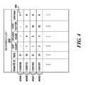
- FIG. 4is a data structure diagrams showing one example of a neighbor list maintained by the RF communication component of a device in an AMI network, according to embodiments described herein.
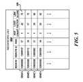
- FIG. 5is a data structure diagrams showing another example of a neighbors list maintained by a host for nodes or devices in an AMI network, according to embodiments described herein.
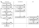
- FIG. 6is a flow diagram showing one routine for selecting a parent for an orphaned node or device in wireless mesh network, according to embodiments described herein.
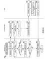
- FIG. 7is a flow diagram showing one routine for collecting information regarding neighboring nodes or devices in a portion of a wireless mesh network to be used to determine new parents for the nodes, according to embodiments described herein.
- a newly installed node in a mesh networkmay dynamically establish a parent based on network information regarding nodes and transmission statistics of nodes within communication range of the newly installed node.
- existing nodesmay be provided with the capability of collecting information regarding the performance of communication links with other nodes within range, and forwarding that information to a server connected to the AMI network in order for the server to determine optimal parent assignment for the nodes in the network. This allows for the routing in the mesh network to be periodically and dynamically reconfigured, ensuring continued optimization and reliability of network.
- the dynamic routing methods described hereinrely on measurement of received signal strength indicator (“RSSI”) of transmissions from neighboring nodes providing a more reliable method of assessing the viability of a node-to-node link.
- RSSIreceived signal strength indicator
- the dynamic routing methods described hereinmay provide viable routes on the first routing attempt as well as providing secondary/alternate routes in the same routing pass, thus improving the reliability of the mesh network.
- FIG. 1is a block diagram showing one example of a network topology of an AMI network 100 , such as that implemented by a utility provider.
- the AMI network 100may include utility provider systems, such as the host 102 .
- the host 102may represent a combination of application servers, database servers, communication servers, web servers, and the like that comprise the systems of the utility provider used to collect data from, control and manage the meters and other devices of the AMI network 100 .
- the host 102may be connected to a variety of devices in the AMI network 100 through various communication links 104 A- 104 D (referred to herein generally as communication links 104 ).
- the communication links 104may include radio frequency (“RF”) communication links, cellular data links, Wi-fi or WiMAX networks links, satellite communication links, metropolitan-area networks (“MANs”), wide-area networks (“WANs”), the Internet, and the like.
- the devices of the AMI network 100may include advanced metering devices 106 A- 106 F (referred to herein generally as meters 106 ), such as electronic water meters, gas meters, electricity meters, and the like, that manage and collect data regarding a customer's used of the utility at the customers location.
- the devices of the AMI network 100may further include communication devices, such as data collection hubs ( 108 A- 108 B (referred to herein generally as hubs 108 ), repeaters 110 , gateways 112 , and the like.
- the AMI network 100may also include other infrastructure communication, monitoring and control devices (not shown), such as valves, sensors, control panels, and the like.
- the AMI network 100may include a number of the devices 106 , 108 , 110 , 112 configured in a mesh networking topology.
- the devices configured in the mesh networkmay comprise a collection of advance metering devices 106 , data collection hubs 108 , repeaters 110 , gateways 112 , and other devices or “nodes” communicating with each other using RF communication links, such as communication link 104 D.
- the mesh networkmay comprise a routed network, with the nodes 106 , 108 , 110 , 112 having predefined “parent” and “child” relationships based on a routing hierarchy determined for the network.
- Each node 106 , 108 , 110 , 112may be assigned one or more parent nodes with which the node may communicate directly, with the parent nodes responsible for relaying the data through other nodes of the mesh network to the intended destination.
- a metering device 106 Fmay send usage data to the host 102 by transmitting the data to its assigned parent node, meter 106 B, which relays the data to its parent, hub 108 A, which is in communication with the host over communication link 104 B.
- the route 114 A(referred to herein generally as routes 114 ) for meter 106 F to communicate with the host 102 may be determined by the parent and child relationships defined between the meter 106 F, the meter 106 B, and the hub 108 A.
- a nodemay be assigned more than one parent node, multiple routes may exist between the node and the host 102 .
- meters 106 Dmay be assigned two parent nodes comprising of meter 106 C and hub 108 B, resulting in two, independent routes 114 B and 114 C between meter 106 D and the host 102 .
- Other configurations of parent and child relationshipsmay be imagined, including a single parent paired with a single child, and it is intended that all such configurations be included in this disclosure.
- the nodes 106 , 108 , 110 , 112 of the wireless mesh networkmay employ frequency-hopping spread spectrum (“FHSS”) technology to transmit and receive data between them.
- FHSSfrequency-hopping spread spectrum
- the nodesmay be configured to comply with F.C.C. rules and regulations part 15 (47 C.F.R. ⁇ 15).
- FHSSis a method of transmitting and receiving radio signals by rapidly switching among many frequency channels using a pseudorandom channel sequence known to both the transmitting and receiving devices.
- each of the nodes 106 , 108 , 110 of the mesh networkmay operate in one of 3 states: a SLEEP state used to conserve battery life; a SLAVE state used for responding to and receiving data from a MASTER state device; and a MASTER state used to initiate communications with (i.e., “hail”) and send data to a SLAVE state device.
- a SLEEP stateused to conserve battery life
- a SLAVE stateused for responding to and receiving data from a MASTER state device
- a MASTER stateused to initiate communications with (i.e., “hail”) and send data to a SLAVE state device.
- SLEEP stateIn SLEEP state, a device partially awakens and briefly listens for a “hailing” signal on a hailing channel from another device in MASTER state. If the device in SLEEP state fails to detect a hailing signal, the device remains in SLEEP state and periodically partially awakens to listen for a hailing signal.
- the SLEEP state devicechanges hailing channels based on a predefined pseudorandom hailing channel frequency set dependent upon a system time. Once the SLEEP state device is “hailed” by a MASTER state device, it fully awakens and begins listening for data messages from the MASTER state device on a predefined data channel selected from the predefined pseudorandom data channel frequency set, the data channel being indicated by the MASTER state device. In other words, the SLEEP state device exits SLEEP state and enters SLAVE state.
- a devicelistens for and receives data messages on a data channel selected from the predefined pseudorandom data channel frequency set.
- the MASTER state deviceindicates which data channel to use by sending a data channel pointer to the target device during the hailing process.
- the SLAVE state deviceAfter receiving each message from the MASTER state device, the SLAVE state device sends an acknowledgement (“ACK”) message to the MASTER state device, indicating a successfully received data message.
- ACKacknowledgement
- the SLAVE state device and the MASTER state devicethen switch to the next data channel in the data channel frequency set and continue communications until all data messages have been sent.
- a deviceIn MASTER state, a device “hails” a SLEEP state device by sending a hailing signal on a hailing channel to the targeted SLEEP state device.
- the MASTER state deviceselects which hailing channel to use based on: 1) the SLEEP state device's predefined pseudorandom hailing channel frequency set, 2) a system time corresponding to the hailing channel frequency set, and 3) an address or “node ID” of the SLAVE state device.
- the node IDis an identifier, such as an alphabetic and/or numeric string, associated with and unique to a device.
- the system time on the MASTER state device and the system time on the SLAVE state deviceare substantially in synchronization.
- the MASTER state deviceUpon successfully “hailing” the sleeping device (which upon hailing becomes a SLAVE state device), the MASTER state device begins sending data messages on a data channel to the SLAVE state device.
- the data channelis selected from the SLAVE state device's predefined pseudorandom data channel set based on the system time.
- the data channel frequency setis common to the MASTER state device and the SLAVE state device.
- the MASTER state devicemay indicate to the SLAVE state device during the hailing procedure what the next available data channel is by sending to the SLAVE state device a data channel pointer.
- hailing channels and data channelsare selected from the 902-928 MHz industrial, scientific, and medical (“ISM”) bandwidth.
- ISMindustrial, scientific, and medical
- one hundred (100) channelsare chosen with a minimum channel spacing of 100 kHz each.
- Fifty (50) of the channelsare randomly assigned to the pseudorandom data channel frequency set, and fifty (50) different channels are randomly assigned to the hailing channel frequency set.
- the set of fifty (50) hailing channelsare used during the MASTER and SLEEP states to send and receive hailing requests while the set of fifty (50) data channels are used during the MASTER and SLAVE states to send and receive data messages.
- hailing channel group 0may include hailing channels 0 and 1 (908.15 MHz and 919.8 MHz), while hailing channel group 1 may include hailing channels 2 and 3 (922.65 MHz and 902.65 MHz), continuing through hailing channel group 24. More generally, hailing channel group “n” may include hailing channel “x” and hailing channel “x+1” where “x” represents a hailing channel. In other embodiments, hailing channel groups may include a different number or combination of hailing channels.
- data channel group 0may include data channels 0 and 1 (922 MHz and 904.5 MHz), while data channel group 1 may include data channels 2 and 3 (908 MHz and 925 MHz), continuing through data channel group 24.
- data channel group “p”may include data channel “y” and data channel “y+1” where “y” represents a data channel.
- data channel groupsmay include a different number or combination of data channels. In some embodiments, the data channels are not grouped.
- a particular deviceselects an initial subset of two (2) consecutive channels (i.e., a channel group) from its predefined pseudorandom hailing channel frequency set to be used while in the SLEEP state by first calculating a channel offset based on its node ID. This offset is added to a hailing channel pointer.
- the hailing channel pointerpoints to one of the fifty (50) available hailing channels, and increments to the next set of two (2) channels every, for example, 18 seconds so that each device will continuously “hop” through all of the fifty (50) available hailing channels at a system hopping rate. In this manner, hailing channel usage is spread across the predefined hailing channel.
- the hailing channel usagemay be substantially equal manner such that each channel within the hailing channel frequency set is used for substantially the same amount of time or for substantially the same number of times. In further embodiments, the hailing channel usage might be skewed to use hailing channels with less interference more frequently while using hailing channels with more interference less frequently.
- the deviceshop through the data channel frequency set to assure that, on average, all data channels are used equally.
- FIG. 2shows a block diagram of an RF communication component 200 of a device 106 , 108 , 110 in the AMI network 100 .
- the RF communication component 200may allow the devices or nodes to communicate with one another over the wireless AMI network.
- the RF communication component 200may be implemented in or connected to an advanced metering device 106 in order to communicate usage data to the host 102 , as described above in regard to FIG. 1 .
- the RF communication component 200may be configured for communication on various radio topologies, including mesh networking, point-to-point, point-to-multipoint, star, and the like. In other embodiments, the RF communication component 200 may be configured to communicate in multiple topologies.
- the RF communication component 200may include a battery 205 that powers a transceiver integrated circuit (“IC”) 210 , a processor 220 , an RF power amplifier 230 , an RF low-noise amplifier 240 , and a memory 250 . Crystal oscillators 215 and 225 are connected to the transceiver IC 210 and the processor 220 , respectively.
- the RF communication component 200further includes a transmit/receive switch 260 and antenna 270 .
- the processor 220may be a microprocessor, a microcontroller, a field-programmable gate array (“FPGA”), or the like.
- the processor 220 and the transceiver IC 210may include both a two-way data and a two-way control line.
- the Processor 220includes a control line to each of the RF low-noise amplifier 240 and the transmit/receive switch 260 .
- the processor 220may also be connected to the memory 250 by both a two-way data line and by a battery status line, the battery line included so that flash memory may notify the processor 220 of its power and battery status.
- the memory 250may comprise a computer-readable storage medium for storing processor-executable instructions, data structures and other information.
- the memory 250may include a non-volatile memory, such as read-only memory (“ROM”) and/or FLASH memory, and a random-access memory (“RAM”), such as dynamic random access memory (“DRAM”) or synchronous dynamic random access memory (“SDRAM”).
- the memory 250may store a firmware that comprises commands and data necessary for the device 106 , 108 , 110 to communicate with other devices in the AMI network 100 as well as perform other operations of the RF communication component 200 .
- the memory 250may store processor-executable instructions that, when executed by the processor 220 , perform portions of the routines 600 and 700 for dynamically determining and assigning parent nodes and routes for nodes in a mesh network, as described herein.
- the RF communication component 200may have access to other computer-readable media storing program modules, data structures, and other data described herein for dynamically determining and assigning parent nodes and routes for nodes in a mesh network.
- computer-readable mediacan be any available media that may be accessed by the processor 220 or other computing system, including computer-readable storage media and communications media.
- Communications mediaincludes transitory signals.
- Computer-readable storage mediaincludes volatile and non-volatile, removable and non-removable storage media implemented in any method or technology for the non-transitory storage of information.
- computer-readable storage mediaincludes, but is not limited to, RAM, ROM, erasable programmable ROM (“EPROM”), electrically-erasable programmable ROM (“EEPROM”), FLASH memory or other solid-state memory technology, compact disc ROM (“CD-ROM”), digital versatile disk (“DVD”), high definition DVD (“HD-DVD”), BLU-RAY or other optical storage, magnetic cassettes, magnetic tape, magnetic disk storage or other magnetic storage devices and the like.
- the processor 220may be further connected to other components of the device 106 , 108 , 110 through a device interface 280 .
- the device interface 280may connect to an electronic utility meter component, such as a water meter or an electricity meter, that allows the meter to provide usage data for transmission through the wireless mesh network.
- the device interface 280may connect to a reporting and testing component, such as a water or gas leak detector, that allow status information and alarms regarding the utility provider's infrastructure to be transmitted through the AMI network 100 by the RF communication component 200 .
- the device interface 280may connect to a control component, such as an electronically actuated water valve, that allows the host 102 or other devices 106 , 108 , 110 on the AMI network 100 to control aspects of the utility provider's infrastructure.
- a control componentsuch as an electronically actuated water valve
- the structure and/or functionality of the RF communication component 200may be different that that illustrated in FIG. 2 and described herein.
- the transceiver IC 210 , processor 220 , RF power amplifier 230 , RF low-noise amplifier 240 , memory 250 , crystal oscillators 215 , 225 , device interface 280 and other components and circuitry of the RF communication component 200may be integrated within a common integrated circuit package or distributed among multiple integrated circuit packages.
- the illustrated connection pathwaysare provided for purposes of illustration and not of limitation, and some components and/or interconnections may be omitted for purposes of clarity.
- the RF communication component 200may not include all of the components shown in FIG. 2 , may include other components that are not explicitly shown in FIG. 2 or may utilize an architecture completely different than that shown in FIG. 2 .
- FIG. 3shows an example computer architecture 300 for a computer 302 capable of executing the software components described herein for dynamically determining and assigning parent nodes and routes for nodes in a mesh network.
- the computer architecture 300 shown in FIG. 3illustrates a conventional server computer, workstation, desktop computer, laptop, or other computing device, and may be utilized to execute any aspects of the software components presented herein described as executing on the host 102 , or other computing platform.
- the computer 302includes a baseboard, or “motherboard,” which is a printed circuit board to which a multitude of components or devices may be connected by way of a system bus or other electrical communication paths.
- one or more central processing units (“CPUs”) 304operate in conjunction with a chipset 306 .
- the CPUs 304are standard programmable processors that perform arithmetic and logical operations necessary for the operation of the computer 302 .
- the CPUs 304perform the necessary operations by transitioning from one discrete, physical state to the next through the manipulation of switching elements that differentiate between and change these states.
- Switching elementsmay generally include electronic circuits that maintain one of two binary states, such as flip-flops, and electronic circuits that provide an output state based on the logical combination of the states of one or more other switching elements, such as logic gates. These basic switching elements may be combined to create more complex logic circuits, including registers, adders-subtractors, arithmetic logic units, floating-point units, or the like.
- the chipset 306provides an interface between the CPUs 304 and the remainder of the components and devices on the baseboard.
- the chipset 306may provide an interface to a memory 308 .
- the memory 308may include a random access memory (“RAM”) used as the main memory in the computer 302 .
- the memory 308may further include a computer-readable storage medium such as a read-only memory (“ROM”) or non-volatile RAM (“NVRAM”) for storing basic routines that that help to startup the computer 302 and to transfer information between the various components and devices.
- ROMread-only memory
- NVRAMnon-volatile RAM
- the ROM or NVRAMmay also store other software components necessary for the operation of the computer 302 in accordance with the embodiments described herein.
- the computer 302may operate in a networked environment using logical connections to remote computing devices through one or more networks 312 , such as the wireless mesh network described herein, a local-area network (“LAN”), a wide-area network (“WAN”), the Internet, or any other networking topology known in the art that connects the computer 302 to the devices and other remote computers.
- the chipset 306includes functionality for providing network connectivity through one or more network interface controllers (“NICs”) 310 , such as a gigabit Ethernet adapter.
- NICsnetwork interface controllers
- the NIC 310may be capable of connecting the computer 302 to the devices 106 , 108 , 110 in the AMI network 100 as well as other computer devices in the utility provider's systems. It should be appreciated that any number of NICs 310 may be present in the computer 302 , connecting the computer to other types of networks and remote computer systems beyond those described herein.
- the computer 302may be connected to a mass storage device 318 that provides non-volatile storage for the computer.
- the mass storage device 318may store system programs, application programs, other program modules, and data, which are described in greater detail herein.
- the mass storage device 318may be connected to the computer 302 through a storage controller 314 connected to the chipset 306 .
- the mass storage device 318may consist of one or more physical storage units.
- the storage controller 314may interface with the physical storage units through a serial attached SCSI (“SAS”) interface, a serial advanced technology attachment (“SATA”) interface, a fiber channel (“FC”) interface, or other standard interface for physically connecting and transferring data between computers and physical storage devices.
- SASserial attached SCSI
- SATAserial advanced technology attachment
- FCfiber channel
- the computer 302may store data on the mass storage device 318 by transforming the physical state of the physical storage units to reflect the information being stored.
- the specific transformation of physical statemay depend on various factors, in different implementations of this description. Examples of such factors may include, but are not limited to, the technology used to implement the physical storage units, whether the mass storage device 318 is characterized as primary or secondary storage, or the like.
- the computer 302may store information to the mass storage device 318 by issuing instructions through the storage controller 314 to alter the magnetic characteristics of a particular location within a magnetic disk drive unit, the reflective or refractive characteristics of a particular location in an optical storage unit, or the electrical characteristics of a particular capacitor, transistor, or other discrete component in a solid-state storage unit.
- the computer 302may further read information from the mass storage device 318 by detecting the physical states or characteristics of one or more particular locations within the physical storage units.
- the mass storage device 318may store an operating system 320 utilized to control the operation of the computer 302 .
- the operating systemcomprises the LINUX operating system.
- the operating systemcomprises the WINDOWS® SERVER operating system from MICROSOFT Corporation of Redmond, Wash.
- the operating systemmay comprise the UNIX or SOLARIS operating systems. It should be appreciated that other operating systems may also be utilized.
- the mass storage device 318may store other system or application programs and data utilized by the computer 302 , such as a routing modules 322 utilized by the computer to dynamically determining and assigning parent nodes and routes for nodes in a mesh network, as described herein.
- the mass storage device 318may be encoded with computer-executable instructions that, when loaded into the computer 302 , may transform the computer from a general-purpose computing system into a special-purpose computer capable of implementing the embodiments described herein. These computer-executable instructions transform the computer 302 by specifying how the CPUs 304 transition between states, as described above.
- the mass storage device 318may store computer-executable instructions that, when executed by the computer 302 , perform portions of the routines 600 and 700 for dynamically determining and assigning parent nodes and routes for nodes in a mesh network, as described herein.
- the computer 302may have access to other computer-readable storage medium in addition to or as an alternative to the mass storage device 318 .
- the computer 302may also include an input/output controller 330 for receiving and processing input from a number of input devices, such as a keyboard, a mouse, a touchpad, a touch screen, an electronic stylus, or other type of input device. Similarly, the input/output controller 330 may provide output to a display device, such as a computer monitor, a flat-panel display, a digital projector, a printer, a plotter, or other type of output device. It will be appreciated that the computer 302 may not include all of the components shown in FIG. 3 , may include other components that are not explicitly shown in FIG. 3 , or may utilize an architecture completely different than that shown in FIG. 3 .
- FIGS. 4 and 5are data structure diagrams showing a number of data elements stored in data structures. It will be appreciated by one skilled in the art that data structures shown in the figure may represent rows in a database table, instances of objects stored in a computer memory, programmatic structures, or any other data container commonly known in the art. Each data element included in the data structure may represent one or more fields or columns of a database table, one or more attributes of an object, one or more member variables of a programmatic structure, or any other unit of data of a data structure commonly known in the art. The implementation is a matter of choice, and may depend on the technology, performance, and other requirements of the computing system upon which the data structures are implemented.
- FIG. 4shows one example of a neighbor list 402 maintained by the RF communication component 200 of a device 106 , 108 , 110 in an AMI network 100 , such as the wireless mesh network described herein.
- the neighbor list 402may be maintained during normal communications with other devices on the network 100 , and/or rebuilt anew when performing operations and routines for dynamically determining and assigning parent nodes and routes for nodes in a mesh network, as described herein.
- the neighbor list 402may be maintained in the memory 250 of the RF communication component 200 .
- the neighbor list 402may contain a number of remote node entries 404 A- 404 D (referred to herein generally as remote node entry 404 ), each entry corresponding to a remote device or node within the mesh network with which the RF communication component 200 may communicate, i.e. is within communication range of the node containing the RF communication component.
- each remote node entry 404may contain the node ID of the remote node.
- the node IDmay represent a unique identifier of the remote node within the network 100 , such as a MAC address of the node, for example.
- Each remote node entry 404may further include a receive signal strength indicator (“RSSI”) measurement associated with the remote node.
- the RSSI measurementmay indicate how much energy is present in a communication channel when the node is receiving communications from the remote node.
- the RSSI measurementmay be obtained from the transceiver IC 210 of the RF communication component 200 , for example.
- Each remote node entry 404may also contain a hop count for the remote node, indicating a number of network hops, or intervening nodes within the mesh network, between the remote node and the host 102 , a hop count of 1 meaning that the remote node is in direct communication with the host.
- Each remote node entry 404may also contain a load factor, indicating a relative number of child or ancestor nodes within the mesh network for which the corresponding remote node acts as a parent node.
- each remote node entry 404may also contain an upload hour, indicating a time slot in which the remote node performs routine uploads of data to the host 102 .
- each remote node entry 404may contain an orphan flag 406 .
- the orphan flag 406may indicate that the remote node is operating in an orphan mode, having lost communication with its parent.
- the orphan flag 406 of the remote node entry 404may be set by the RF communication component 200 when the information regarding the remote node is received in an orphan notice broadcast, as will be described in more detail below. It will be appreciated that additional data elements may be maintained in the neighbor list 402 for each remote node entry 404 beyond those described herein, and that not every data element or attribute described will be available for every remote node entry 404 in the neighbor list.
- FIG. 5shows another example of a neighbors list 502 maintained by the host 102 for the nodes or devices 106 , 108 , 110 in the AMI network 100 , according to some embodiments.
- the neighbors list 502may be compiled from the neighbor list 402 of each individual node or device 106 , 108 , 110 in the mesh network.
- the neighbor list 402 of the devices 106 , 108 , 110 in the mesh networkmay be periodically uploaded to the host 102 and/or may be requested by the host performing operations and routines for dynamically determining and assigning parent nodes and routes for nodes in a mesh network, as described herein.
- the neighbors list 502may be maintained by the routing module 322 in the memory 308 of a computer 302 comprising the host 102 or other computer system of the utility provider.
- the neighbors list 502may contain neighboring nodes entries 504 A- 504 D (referred to herein generally as neighboring nodes entry 504 ), each entry corresponding to a pair of neighboring devices or node within the mesh network, i.e. a pair of nodes that are within communication range of each other.
- each neighboring nodes entry 504may contain the node ID of the node that reported the communication parameters for the pair of nodes as well as the node ID of the remote node to which the communication parameters pertain.
- Each neighboring nodes entry 504may further include the (“RSSI”) measurement measured by the reporting node for the remote node, and the hop count associated with the remote node.
- Each neighboring nodes entry 504may also contain the load factor for the remote node.
- each neighboring nodes entry 504may also contain a link score 506 .
- the link score 506may indicate a relative viability of the communication link 104 between the neighboring nodes or devices 106 , 108 , 110 within the network and may be calculated by the routing module 322 from one or more of the communication parameters in the neighboring nodes entry 504 pertaining to the neighboring nodes.
- the link score 506may be further utilized by the routing module 322 for dynamically determining and assigning parent nodes and routes for nodes in a mesh network, as described below.
- the link score 506may be calculated from the RSSI measurement between the nodes.
- the link score 506may be calculated from an algorithm that combines the weighted value of the factors shown below in Table 3. The factors may be calculated from the communication parameters for the neighboring nodes from the corresponding neighboring nodes entry 504 , as shown.
- FIG. 6is a flow diagram showing one method for dynamically determining and assigning parent nodes and routes for nodes in a mesh network, according to some embodiments.
- FIG. 6illustrates one routine 600 for selecting a parent for an orphaned node or device 106 , 108 , 110 in wireless mesh network comprising the AMI network 100 .
- an orphan modemay be utilized by a node in the wireless mesh network when newly installed or when communications with a parent node have been lost. The orphan mode allows the node to discover potential links with other, neighboring nodes (i.e., nodes in communication range) based on RSSI measurements or other communication parameters regarding communications with the neighboring nodes.
- the routine 600may be performed by a combination of the RF communication component 200 of the orphaned node, the communication component of neighboring node(s), and the routing module 322 of the host 102 , as shown in the figure. In other embodiments, the routine 600 may be performed by the RF communication component 200 of the orphaned node (device 106 , 108 , 110 ), by the host 102 , by other processors or computing systems performing routing for the AMI network 100 , or by some other combination of modules, processors and devices.
- the RF communication component 200 of the orphaned nodemay enter the orphan mode when it is detected that communications with its assigned parent are lost, e.g. when successfully communications with its assigned parent have not been performed for some period of time or after some number of failures of handshake (hails) between node and parent have occurred.
- the RF communication component 200may enter orphan mode when it has been without a parent for 10 days.
- the RF communication component 200 of the orphaned nodemay also enter the orphan mode upon receiving a command from the host 102 .
- an administrator of the utility provider's infrastructuremay cause the host 102 to send an orphan mode command message to one or more meters 106 , hubs 108 and/or repeaters 110 in the AMI network 100 in order to initially perform routing in newly installed devices or optimize routing in an existing portion of the network.
- the RF communication component 200 of the orphaned nodemay also enter the orphan mode upon receiving input locally by an installer, repair technician, or other authorized personnel of the utility provider.
- the routine 600begins at step 602 , where the RF communication component 200 of the orphaned node broadcasts an orphan notice over the wireless network.
- the RF communication component 200may broadcast an orphan notice over all 50 of the available hailing channels.
- the orphan noticemay include the message elements or fields described below in Table 4.
- step 604the RF communication component 200 of the orphaned mode begins to listen for neighbor notices from neighboring nodes or devices 106 , 108 , 110 in the mesh network for some listening period of time.
- all devices 106 , 108 , 110 on the wireless mesh networkare configured to respond to orphan notices when received from any node within communication range.
- step 606when an orphan notice is received at a neighboring node, the routine proceeds to step 608 , where the RF communication component 200 of the neighboring node may respond to the broadcast orphan notice with a neighbor notice including the message elements or fields described below in Table 5.
- the neighboring nodemay wait a random period of time, such as between one minute and an hour, after receiving the orphan notice before sending the neighbor notice.
- the neighbor noticeis sent to the orphaned node on one or more hailing channels depending on the FHSS channel selection algorithm, the current time, and the node ID of the orphaned node, as described above in regard to FIG. 1 .
- the neighbor noticemay be broadcast on all 50 of the available hailing channels.
- the RF communication component 200 of the neighboring nodefurther adds a remote node entry 404 for the orphaned node in its neighbor list 402 , as shown at step 610 .
- the remote node entry 404may include at least the node ID of the orphaned and the RSSI measurement of the received orphan notice.
- the remote node entry 404may further include the orphan flag 406 indicating that the remote node is operating in orphan mode. This new remote node entry 404 may be provided to the host 102 with the next upload of the neighbor list 402 from the neighboring node, as is described below in regard to step 618 .
- the neighboring nodemay attempt to sync with the orphaned node in order to re-establish communications with the node. If a hail is received from a purported parent node by a node operating in orphan mode, the RF communication component 200 of the orphaned node may cancel the orphan mode and sync with the parent node, before returning to normal operation.
- the RF communication component 200 of the orphaned nodemay enter a “super-sniff” state in order to listen for neighbor notices from neighboring nodes in the mesh network.
- the orphaned modemay periodically wakeup from the SLEEP state and listens on all 50 hailing channels for the neighbor notices. Because the orphaned node may not have synched with its parent for an extended period of time, the system time maintained by the node may not be correct, and therefore relying on the channel selection algorithm may not yield the proper hailing channel(s) to which to listen for the neighbor notices.
- the orphaned nodemaximizes the chance of hearing the neighbor notices from all neighboring nodes within communication range.
- the routine 600proceeds to step 614 , where the RF communication component 200 of the orphaned node adds a remote node entry 404 for the neighboring node in its neighbor list 402 , including at least the node ID of the neighboring node and the RSSI measurement of the received neighbor notice, along with the hop count, upload hour, and load factor included in the neighbor notice, if specified.
- the routine 600next proceeds to step 616 , where the RF communication component 200 determines whether the listening period has expired. For example, the RF communication component 200 may be configured to listen for neighbor notices for one hour after broadcasting its orphan notice. If the listening period has not expired, then the routine 600 returns to step 604 , where the RF communication component 200 continues to listen for neighbor notices from neighboring nodes on the network.
- the neighboring nodeuploads its neighbor list 402 to the host 102 , as shown at step 618 .
- the neighboring nodemay upload its neighbor list 402 on a regularly scheduled basis, for example, or in response to receiving the orphan notice from the orphaned node.
- the neighboring nodemay upload its neighbor list 402 in response to a request or command received from the host 102 .
- the uploaded neighbor list 402will contain the remote node entry 404 having the orphan flag 406 indicating that the orphaned node is operating in orphan mode, according to some embodiments.
- the orphaned nodemay also upload its neighbor list 402 to the host 102 .
- the RF communication component 200may select a best node from its newly created neighbor list 402 as its parent node for transmitting the data containing the neighbor list to the host. For example, the RF communication component 200 may select the remote node in the neighbor list 402 having the highest RSSI measurement, the lowest hop count, and/or the like with which to communicate for uploading the neighbor list to the host 102 .
- the RF communication component 200 of the orphaned nodemay utilize a similar method to select a node from the neighbor list 402 with which to communicate in order to upload its neighbor list to the host.
- the host 102receives the neighbor lists 402 from the neighboring node(s) and/or the orphaned node.
- the routine 600proceeds from step 620 to step 622 , where the routing module 322 executing on the host 102 determines one or more parent nodes for the orphaned mode based on the link score 506 calculated for all of the neighboring nodes of the orphaned node.
- the host 102may wait some period after sending the orphan mode command to the node for any neighboring nodes (and possibly the orphaned node) to upload neighbor lists 402 to the host. For example, the host 102 may wait 3 days for all affected nodes to upload neighbor lists 402 .
- the routing module 322 on the hostmay then add the remote node entries 404 from the uploaded neighbor lists 402 to the host's neighbors list 502 , calculating a link score 506 for each pair of neighboring nodes, as described above in regard to FIG. 5 .
- the routing module 322may then select one or more parent nodes for the orphaned node based on the link scores 506 for the associated neighboring nodes entries 504 .
- the routine 600proceeds from step 622 to step 624 , where the routing module 322 assigns the selected parent nodes to the orphaned node.
- the routing module 322may send a configuration command message to the orphaned node via one of the selected (primary) parent nodes to assign the selected parent(s) the orphaned node.
- the orphaned nodethen reconfigures based on the message and begins communicating through the newly assigned parent node(s), as shown at step 626 .
- the routing module 322may send configuration command message to multiple nodes based on the changed neighboring nodes entries 504 from the uploaded neighbor lists 402 and the recalculated link scores 506 in order to perform re-routing of a portion of the mesh network. From step 626 , the routine 600 ends.
- the orphan mode routine 600 described abovemay be utilized by a repeater 110 in the AMI network 100 in order to reroute the network in response to the new installation of the repeater or to optimize routing in an existing portion of the network. While the repeater 110 may have valid assigned parent nodes, it may enter the orphan mode upon receiving a command from the host 102 or upon receiving input locally by an installer, repair technician, or other authorized personnel. After sending the orphan notice and receiving neighbor notices from neighboring nodes, the repeater 110 may then upload its newly built neighbor list 402 to the host 102 , where the information contained therein may be utilized by the routing module 322 to assign new parents to nodes within communication range of the repeater.
- FIG. 7is a flow diagram showing another method for dynamically determining and assigning parent nodes and routes for nodes in a mesh network, according to some embodiments.
- FIG. 7illustrates one routine 700 for collecting information regarding neighboring nodes or devices 106 , 108 , 110 in a portion of a wireless mesh network comprising the AMI network 100 to be used to determine new parents for the nodes.
- a discovery modemay be utilized by nodes to collect neighbor lists 402 with RSSI measurements and upload these neighbor lists to the host 102 using the existing routes in the network. The server may then use the uploaded neighbor lists 402 to perform new routing within the subset of nodes and push the new parent assignments back to the nodes through the network.
- the routine 700may be performed by a combination of the routing module 322 of the host 102 and the RF communication component 200 of the affected nodes (devices 106 , 108 , 110 ) in the mesh network, as shown in the figure. In other embodiments, the routine 700 may be performed by the host 102 , by the RF communication component 200 of one or more devices 106 , 108 , 110 , by other processors or computing systems performing routing for the AMI network 100 , or by some other combination of modules, processors and devices.
- the routine 700begins at step 702 , where the routing module 322 on the host 102 sends a discovery mode command message to one or more nodes or devices 106 , 108 , 110 on the mesh network.
- the discovery mode command messagemay be sent periodically by the routing module 322 as part of a scheduled re-routing routine for the subset of nodes, or may be sent in response to an action by an administrator of the utility provider's infrastructure. For example, the administrator may select the subset of nodes for which dynamic re-routing is to be performed, thereby causing the routing module 322 to send the discovery mode command message to the selected nodes.
- the discovery mode command messagemay include a start time and duration in which to the node(s) are to operate in discovery mode.
- the discovery mode command messagefurther includes a number of times, e.g. a number of days, that the discovery mode process should be repeated.
- the nodes of the wireless mesh networkmay be configured to enter discovery mode at some scheduled time, without having to receive a discovery mode command message from the host 102 .
- the routineproceeds from step 702 to step 704 , where the RF communication components 200 of the affected nodes begin to listen for all communications from neighbor nodes or devices 106 , 108 , 110 in the mesh network the specified duration.
- the RF communication component 200utilizes a “promiscuous” state in order to listen for communications between neighboring nodes in the mesh network. Similar to the super-sniff state described above, the RF communication component 200 in the promiscuous state periodically wakeups from the SLEEP state and listens to one or more of the 50 hailing channels and/or 50 data channels for communication traffic. In some embodiments, the RF communication component may listen on all 50 hailing channels and/or data channels for traffic. According to embodiments, the RF communication component 200 may scan a subset of the hailing and/or data channels for some period before returning to the SLEEP state.
- step 706when a communication between neighboring nodes is detected, e.g. when the RSSI on the scanned channel is above some threshold indicating a transmission is taking place, the routine 700 proceeds to step 708 , where the RF communication component 200 of the node adds a remote node entry 404 to its neighbor list 402 , including at least the source node ID and the RSSI measurement of the detected communication.
- the routine 700next proceeds to step 710 , where the RF communication component 200 determines whether the specified listening duration has expired. If the listening duration has not expired, then the routine 700 returns to step 704 , where the RF communication component 200 continues to scan the hailing and/or data channels for communications between neighboring nodes.
- the routine 700proceeds from step 710 to step 712 , where the RF communication components 200 of the affected nodes upload their neighbor lists 402 to the host 102 .
- the neighbor list 402may be uploaded to the host 102 using the existing routes, e.g. the existing parent assignments, in the mesh network.
- the routine 700proceeds to step 714 , where the routing module 322 executing on the host determines one or more parent nodes for the affected nodes based on the link score 506 calculated for all of the neighboring nodes entries 504 updated from the uploaded neighbor lists 402 .
- the host 102may wait some period after sending the discovery mode command to the nodes for the affected nodes to upload their neighbor lists 402 .
- the host 102may wait 3 days for all affected nodes to upload neighbor lists 402 .
- the routing module 322 on the hostmay then add the remote node entries 404 from the uploaded neighbor lists 402 to the host's neighbors list 502 , and recalculate link scores 506 for each pair of neighboring nodes, as described above in regard to FIG. 5 .
- the routing modulemay then select one or more parent nodes for each of the affected nodes based on the link scores 506 for the associated neighboring nodes entries 504 .
- the routine 700proceeds from step 714 to step 716 , where the routing module 322 assigns the selected parent nodes to the orphaned node. For example, the routing module 322 may send configuration command messages to the affected nodes via the existing routes in the mesh network to assign the selected parent(s) to each node. In response to receiving a configuration command message from the host 102 , the target node then reconfigures based on the message and begins communicating through the newly assigned parent node(s). From step 716 , the routine 700 ends.
- logical operations, functions or steps described herein as part of a method, process or routinemay be implemented (1) as a sequence of processor-implemented acts, software modules or portions of code running on a controller or computing system and/or (2) as interconnected machine logic circuits or circuit modules within the controller or computing system.
- the implementationis a matter of choice dependent on the performance and other requirements of the system. Alternate implementations are included in which operations, functions or steps may not be included or executed at all, may be executed out of order from that shown or discussed, including substantially concurrently or in reverse order, depending on the functionality involved, as would be understood by those reasonably skilled in the art of the present disclosure.
- conditional languagesuch as, among others, “can,” “could,” “might,” or “may,” unless specifically stated otherwise, or otherwise understood within the context as used, is generally intended to convey that certain embodiments include, while other embodiments do not include, certain features, elements and/or steps.
- conditional languageis not generally intended to imply that features, elements and/or steps are in any way required for one or more particular embodiments or that one or more particular embodiments necessarily include logic for deciding, with or without user input or prompting, whether these features, elements and/or steps are included or are to be performed in any particular embodiment.
Landscapes
- Engineering & Computer Science (AREA)
- Computer Networks & Wireless Communication (AREA)
- Signal Processing (AREA)
- Mobile Radio Communication Systems (AREA)
Abstract
Description
| TABLE 1 |
| Hailing Channel Frequency Set |
| Ch. | Freq. | Ch. | Freq. | Ch. | Freq. | Ch. | Freq. |
| 0 | 926.8 | 1 | 922.96 | 2 | 925.48 MHz | 3 | 922.72 |
| 4 | 922 MHz | 5 | 925.96 | 6 | 922.84 MHz | 7 | 922.48 MHz |
| 8 | 923.32 MHz | 9 | 925 | 300 | 923.2 MHz | 11 | 924.52 MHz |
| 12 | 925.12 MHz | 13 | 922.6 MHz | 14 | 923.68 MHz | 15 | 925.36 MHz |
| 16 | 924.16 | 17 | 927.76 MHz | 18 | 927.88 MHz | 19 | 927.4 |
| 20 | 924.76 MHz | 21 | 924.28 | 22 | 926.92 MHz | 23 | 926.44 MHz |
| 24 | 927.16 MHz | 25 | 922.63 MHz | 26 | 924.04 MHz | 27 | 923.92 MHz |
| 28 | 923.56 | 29 | 923.08 MHz | 30 | 922.24 | 31 | 927.28 MHz |
| 32 | 926.2 MHz | 33 | 926.08 | 34 | 923.8 MHz | 35 | 924.88 MHz |
| 36 | 925.24 | 37 | 925.84 MHz | 38 | 923.44 MHz | 39 | 927.52 MHz |
| 40 | 922.12 MHz | 41 | 926.56 MHz | 42 | 924.64 MHz | 43 | 927.64 MHz |
| 44 | 924.4 MHz | 45 | 927.04 MHz | 46 | 926.68 MHz | 47 | 925.72 MHz |
| 48 | 926.32 MHz | 49 | 925.6 MHz | ||||
| TABLE 2 |
| Data Channel Frequency Sets |
| Ch. | Freq. | Ch. | Freq. | Ch. | Freq. | Ch. | Freq. |
| 0 | 922.94 | 1 | 922.1 | 2 | 923.78 MHz | 3 | 922.46 |
| 4 | 926.9 MHz | 5 | 927.26 | 6 | 922.82 MHz | 7 | 923.3 MHz |
| 8 | 927.86 MHz | 9 | 927.5 | 300 | 923.9 MHz | 11 | 926.42 MHz |
| 12 | 925.46 MHz | 13 | 927.38 MHz | 14 | 926.3 MHz | 15 | 925.7 MHz |
| 16 | 925.1 | 17 | 926.18 MHz | 18 | 925.94 MHz | 19 | 924.02 |
| 20 | 927.98 MHz | 21 | 926.66 | 22 | 924.98 MHz | 23 | 927.62 MHz |
| 24 | 924.74 MHz | 25 | 925.22 MHz | 26 | 925.34 MHz | 27 | 924.62 MHz |
| 28 | 924.5 | 29 | 926.54 MHz | 30 | 924.14 | 31 | 923.66 MHz |
| 32 | 925.58 MHz | 33 | 922.22 | 34 | 924.26 MHz | 35 | 927.02 MHz |
| 36 | 922.34 | 37 | 926.06 MHz | 38 | 926.78 MHz | 39 | 923.42 MHz |
| 40 | 927.74 MHz | 41 | 924.86 MHz | 42 | 924.38 MHz | 43 | 922.7 MHz |
| 44 | 922.58 MHz | 45 | 925.82 MHz | 46 | 923.54 MHz | 47 | 927.14 MHz |
| 48 | 923.18 MHz | 49 | 923.06 MHz | ||||
| TABLE 3 |
| Factors for Link Score |
| Factor | Definition | Formula | Weight |
| Link Strength | How good is the | (RSSI − 15)/48 | 50 |
| actual link | |||
| Hop Factor | How | 1/(Hop Count)2 | 40 |
| Parent Burden | How much is it | (100 − # ancestors)/100 | 10 |
| (Load Factor) | used | for battery powered device; | |
| (500 − # ancestors)/500 | |||
| for repeater; | |||
| 1 for electrically connected | |||
| device; | |||
It will be appreciated that additional data elements may be maintained in the
| TABLE 4 |
| Orphan Notice Message |
| Field | Offset | Bytes | Description |
| 0xC4 | 0 | 1 | Start of Packet Mark |
| 0x10 | 1 | 1 | Packet type: |
| 0xffffffff | |||
| 2 | 4 | Broadcast address | |
| <SRC> | 6 | 4 | Node ID or address |
| <PPRNT> | 10 | 4 | Primary parent (0 = none configured) |
| <CRC16> | 14 | 2 | CRC-16 for packet |
| TABLE 5 |
| Neighbor Notice Message |
| Field | Offset | Bytes | Description |
| 0xC4 | 0 | 1 | Start of Packet Mark |
| 0x11 | 1 | 1 | Packet type: |
| 0xffffffff | |||
| 2 | 4 | Broadcast address | |
| <SRC> | 6 | 4 | Node ID or address |
| <HOP> | 10 | 1 | Hop Count, 0xff = unknown |
| <UHOUR> | 11 | 1 | Upload Hour, 0xff = unknown |
| <LOAD> | 12 | 1 | Load Factor, 0xff = unknown |
| <CRC16> | 14 | 2 | CRC-16 for packet |
Claims (20)
Priority Applications (2)
| Application Number | Priority Date | Filing Date | Title |
|---|---|---|---|
| US14/475,050US9565620B2 (en) | 2014-09-02 | 2014-09-02 | Dynamic routing in a mesh network |
| PCT/US2015/044140WO2016036475A1 (en) | 2014-09-02 | 2015-08-07 | Dynamic routing in a mesh network |
Applications Claiming Priority (1)
| Application Number | Priority Date | Filing Date | Title |
|---|---|---|---|
| US14/475,050US9565620B2 (en) | 2014-09-02 | 2014-09-02 | Dynamic routing in a mesh network |
Publications (2)
| Publication Number | Publication Date |
|---|---|
| US20160066249A1 US20160066249A1 (en) | 2016-03-03 |
| US9565620B2true US9565620B2 (en) | 2017-02-07 |
Family
ID=55404190
Family Applications (1)
| Application Number | Title | Priority Date | Filing Date |
|---|---|---|---|
| US14/475,050Active2035-02-12US9565620B2 (en) | 2014-09-02 | 2014-09-02 | Dynamic routing in a mesh network |
Country Status (2)
| Country | Link |
|---|---|
| US (1) | US9565620B2 (en) |
| WO (1) | WO2016036475A1 (en) |
Cited By (10)
| Publication number | Priority date | Publication date | Assignee | Title |
|---|---|---|---|---|
| US10039018B2 (en) | 2011-10-27 | 2018-07-31 | Mueller International, Llc | Systems and methods for recovering an out-of-service node in a hierarchical network |
| US10070403B2 (en) | 2016-03-09 | 2018-09-04 | Mueller International, Llc | Time beacons |
| US10097411B2 (en) | 2016-05-23 | 2018-10-09 | Mueller International, Llc | Node migration |
| US20180352441A1 (en)* | 2017-06-02 | 2018-12-06 | Atc Technologies, Llc | Devices, methods, and systems with dynamic spectrum sharing |
| US10178617B2 (en) | 2017-05-01 | 2019-01-08 | Mueller International, Llc | Hail and acceptance for battery-powered devices |
| US10200947B2 (en) | 2016-07-11 | 2019-02-05 | Mueller International, Llc | Asymmetrical hail timing |
| US10267652B1 (en) | 2018-01-23 | 2019-04-23 | Mueller International, Llc | Node communication with unknown network ID |
| US10582347B2 (en) | 2016-04-14 | 2020-03-03 | Mueller International, Llc | SMS communication for cellular node |
| US10797897B2 (en) | 2017-09-27 | 2020-10-06 | International Business Machines Corporation | Multi-step remote packet broadcasting/multicasting mechanism for cognitive systems |
| US12267215B2 (en)* | 2022-10-25 | 2025-04-01 | Zoom Communications, Inc. | Dynamic and configurable local mesh network for video conference |
Families Citing this family (17)
| Publication number | Priority date | Publication date | Assignee | Title |
|---|---|---|---|---|
| US10051587B2 (en)* | 2015-07-09 | 2018-08-14 | Google Llc | System for network discovery and synchronization |
| CN106453460B (en)* | 2015-08-12 | 2021-01-08 | 腾讯科技(深圳)有限公司 | File distribution method, device and system |
| US9967884B2 (en) | 2015-11-10 | 2018-05-08 | Netgear, Inc. | Dedicated backhaul for whole home coverage |
| US9980160B2 (en)* | 2015-11-25 | 2018-05-22 | Terranet Ab | Interference mitigation in dense mesh networks |
| US9807621B1 (en)* | 2016-05-17 | 2017-10-31 | Google Inc. | Distributed channel sampling across a mesh network |
| US10356681B2 (en) | 2016-09-21 | 2019-07-16 | Netgear, Inc. | Client roaming in a distributed multi-band wireless networking system |
| US10063943B2 (en) | 2016-10-27 | 2018-08-28 | Itron, Inc. | Events and scheduling for communication in wireless networks |
| US10554369B2 (en)* | 2016-12-30 | 2020-02-04 | Itron, Inc. | Group acknowledgement message efficiency |
| US10887856B2 (en)* | 2017-08-07 | 2021-01-05 | Primex Wireless, Inc. | Adaptive mesh synchronized time network |
| US10491515B2 (en)* | 2017-09-13 | 2019-11-26 | Cisco Technology, Inc. | Fast and loss-free local recovery by a RPL parent device |
| US11159984B2 (en)* | 2018-03-12 | 2021-10-26 | Parallel Wireless, Inc. | Role assignment for caching |
| US11457080B1 (en)* | 2018-11-23 | 2022-09-27 | Amazon Technologies, Inc. | Service mesh management |
| US11106614B2 (en)* | 2019-10-29 | 2021-08-31 | Dell Products L.P. | Asymmetric logical unit access path selection system |
| US11096108B2 (en)* | 2019-10-29 | 2021-08-17 | Dell Products L.P. | Asymmetric logical unit access path selection system |
| CN114258043B (en)* | 2020-09-25 | 2024-07-05 | 瑞昱半导体股份有限公司 | Distribution network system and method thereof |
| US20230349726A1 (en)* | 2022-05-02 | 2023-11-02 | Aclara Technologies Llc | Systems and methods for orphaned sensor discovery and reporting |
| US20250089024A1 (en)* | 2023-09-11 | 2025-03-13 | Honeywell International Inc. | Systems and methods for servicing orphaned sensors in a building control system |
Citations (370)
| Publication number | Priority date | Publication date | Assignee | Title |
|---|---|---|---|---|
| US691904A (en) | 1898-08-20 | 1902-01-28 | David Verner Hallbergh | Water-meter. |
| US1165429A (en) | 1915-01-15 | 1915-12-28 | Adolph Mass | Liquid-meter. |
| US1788618A (en) | 1929-11-06 | 1931-01-13 | Berkey E Cover | Signal system |
| US1808209A (en) | 1923-12-21 | 1931-06-02 | Earl George Goodell | Fluid metering system and apparatus |
| US1808212A (en) | 1931-06-02 | Meter | ||
| US2302529A (en) | 1939-03-07 | 1942-11-17 | Pittsburgh Equitable Meter Co | Dfpeating valve shutoff system |
| US3254660A (en) | 1963-12-19 | 1966-06-07 | Itt | Closure operator for valves |
| US3593957A (en) | 1969-08-15 | 1971-07-20 | Eaton Yale & Towne | Diaphragm assembly for pressure operated pilot controlled shutoff valve |
| US3653261A (en) | 1970-03-06 | 1972-04-04 | Richard Ruben | Pressure demand meter for fluid flow measurement |
| US3672233A (en) | 1970-07-06 | 1972-06-27 | Clare & Co C P | Actuator mechanism |
| US3705385A (en) | 1969-12-10 | 1972-12-05 | Northern Illinois Gas Co | Remote meter reading system |
| US3731534A (en) | 1970-11-18 | 1973-05-08 | Rockwell Mfg Co | Housing structure for meters |
| US3795144A (en) | 1972-02-17 | 1974-03-05 | R Marchesi | Tamper-proof water meter |
| US4093997A (en) | 1976-09-17 | 1978-06-06 | General Electric Company | Portable programmer for time-of-day metering register system and method of using same |
| US4120031A (en) | 1976-07-19 | 1978-10-10 | Energy Conservation Systems, Inc. | Utility usage monitoring systems |
| US4126338A (en) | 1974-04-24 | 1978-11-21 | Badger Meter, Inc. | Threaded coupling |
| US4291375A (en) | 1979-03-30 | 1981-09-22 | Westinghouse Electric Corp. | Portable programmer-reader unit for programmable time registering electric energy meters |
| US4388690A (en) | 1979-10-11 | 1983-06-14 | Ael Microtel Limited | Automatic meter reading transponder |
| US4414633A (en) | 1980-11-17 | 1983-11-08 | British Gas Corporation | Data processing and recording apparatus |
| US4442492A (en) | 1979-08-21 | 1984-04-10 | Karlsson Bjoern G E | Device for central reading and registration of customers' power consumption |
| US4465970A (en) | 1981-02-26 | 1984-08-14 | General Electric Company | Method and apparatus for multiple rate metering of electrical energy |
| US4516213A (en) | 1982-02-01 | 1985-05-07 | E. Grant Deans | Multiple rate metering system |
| US4542469A (en) | 1982-08-12 | 1985-09-17 | Duncan Electric Company, Inc. | Programmable demand register with two way communication through an optical port and external reading devices associated therewith |
| US4591988A (en) | 1983-07-13 | 1986-05-27 | Control Energy Corporation | Energy cost allocation method and system |
| US4707852A (en) | 1981-10-09 | 1987-11-17 | Systems And Support, Incorporated | Utility usage data and event data acquisition system |
| JPS62295674A (en) | 1986-06-16 | 1987-12-23 | 松下電工株式会社 | Disasters preventing monitor control system |
| US4727900A (en) | 1986-12-11 | 1988-03-01 | Dooling Joseph S | Tamper-proof hydrant cover |
| US4778204A (en) | 1985-09-08 | 1988-10-18 | Benjamin Berger | Pipeline connector for plastic instruments |
| US4792946A (en) | 1987-04-07 | 1988-12-20 | Spectrum Electronics, Inc. | Wireless local area network for use in neighborhoods |
| US4803632A (en) | 1986-05-09 | 1989-02-07 | Utility Systems Corporation | Intelligent utility meter system |
| US4833618A (en) | 1986-02-20 | 1989-05-23 | Net Laboratories, Inc. | System for automatically reading utility meters from a remote location |
| US4868566A (en) | 1988-05-03 | 1989-09-19 | Badger Meter, Inc. | Flexible piezoelectric switch activated metering pulse generators |
| US4881070A (en) | 1985-06-21 | 1989-11-14 | Energy Innovations, Inc. | Meter reading methods and apparatus |
| US4901751A (en) | 1989-06-15 | 1990-02-20 | Systems Chemistry, Inc. | Fluid control valve and system with leak detection and containment |
| US4940976A (en) | 1988-02-05 | 1990-07-10 | Utilicom Inc. | Automated remote water meter readout system |
| US4953403A (en) | 1989-03-15 | 1990-09-04 | Binks Manufacturing Company | Positive displacement flushable flow meter |
| US4967996A (en) | 1988-06-28 | 1990-11-06 | Masako Kiyohara | Pilot type controlled electromagnetic valve system |
| US4989830A (en) | 1990-01-26 | 1991-02-05 | Ratnik Industries, Inc. | Motorized hydrant |
| US5056107A (en) | 1990-02-15 | 1991-10-08 | Iris Systems Inc. | Radio communication network for remote data generating stations |
| US5075792A (en) | 1989-03-20 | 1991-12-24 | Hewlett-Packard Company | Low power optical transceiver for portable computing devices |
| US5079715A (en) | 1987-12-28 | 1992-01-07 | Krishnan Venkataraman | Electronic data recorder for electric energy metering |
| US5121344A (en) | 1989-07-03 | 1992-06-09 | The United States Of America As Represented By The Secretary Of The Interior | Method of locating underground mines fires |
| US5239575A (en) | 1991-07-09 | 1993-08-24 | Schlumberger Industries, Inc. | Telephone dial-inbound data acquisition system with demand reading capability |
| JPH05253316A (en) | 1992-03-12 | 1993-10-05 | Senju Sprinkler Kk | Extinguishing equipment |
| US5251480A (en) | 1992-06-02 | 1993-10-12 | Schlumberger Industries, Inc. | Frost-proof drive shaft for water meter |
| US5261275A (en) | 1991-09-12 | 1993-11-16 | Davis Robert J | Water meter system |
| US5267587A (en) | 1992-04-07 | 1993-12-07 | Brown Geoffrey P | Utilities shutoff system |
| US5298894A (en) | 1992-06-17 | 1994-03-29 | Badger Meter, Inc. | Utility meter transponder/antenna assembly for underground installations |
| JPH06223279A (en) | 1993-01-26 | 1994-08-12 | Nohmi Bosai Ltd | Tunnel disaster preventing equipment |
| US5371734A (en) | 1993-01-29 | 1994-12-06 | Digital Ocean, Inc. | Medium access control protocol for wireless network |
| US5381136A (en) | 1993-03-19 | 1995-01-10 | Northern Illinois Gas Company | Remote data collection and monitoring system for distribution line |
| US5434911A (en) | 1993-06-04 | 1995-07-18 | M & Fc Holding Company, Inc. | Call in-bound remote reading and data collection system |
| US5438329A (en) | 1993-06-04 | 1995-08-01 | M & Fc Holding Company, Inc. | Duplex bi-directional multi-mode remote instrument reading and telemetry system |
| US5437481A (en) | 1993-10-13 | 1995-08-01 | Spears Manufacturing Company | Durable plastic/metal transition fitting |
| JPH07231363A (en) | 1994-02-18 | 1995-08-29 | Toyo Puropan Gas Kk | Emergency call network system |
| US5451938A (en) | 1993-10-22 | 1995-09-19 | Schlumberger Industries, Inc. | RF meter reading system |
| US5459459A (en) | 1992-12-28 | 1995-10-17 | General Electric Company | Method and apparatus for transmitting data from an energy meter |
| JPH07116285B2 (en) | 1989-01-17 | 1995-12-13 | ゼネラル・エレクトリック・カンパニイ | Branched thermoplastic polycarbonate and method for producing the same |
| US5481259A (en) | 1994-05-02 | 1996-01-02 | Motorola, Inc. | Method for reading a plurality of remote meters |
| US5493287A (en) | 1994-03-07 | 1996-02-20 | Motorola, Inc. | Method of remotely reading a group of meters |
| US5509567A (en) | 1995-06-07 | 1996-04-23 | State Industries, Inc. | Tank connector construction |
| US5519387A (en) | 1994-04-14 | 1996-05-21 | Motorola, Inc. | Utility meter assembly and remote module and mounting apparatus and assembly |
| US5525898A (en) | 1994-12-16 | 1996-06-11 | General Electric Company | Programmable multi-channel load profile recorder and method of recording electrical energy metering quantities therein |
| US5553094A (en) | 1990-02-15 | 1996-09-03 | Iris Systems, Inc. | Radio communication network for remote data generating stations |
| US5590179A (en) | 1993-02-12 | 1996-12-31 | Ekstrom Industries, Inc. | Remote automatic meter reading apparatus |
| US5594740A (en) | 1993-08-27 | 1997-01-14 | Axion Logistics Corporation | Wireless communications application specific enabling method and apparatus |
| US5594776A (en) | 1994-09-14 | 1997-01-14 | Ericsson Inc. | Efficient paging system |
| US5617084A (en) | 1993-09-10 | 1997-04-01 | Sears; Lawrence M. | Apparatus for communicating utility usage-related information from a utility usage location to a utility usage registering device |
| US5631554A (en) | 1993-03-26 | 1997-05-20 | Schlumberger Industries, Inc. | Electronic metering device including automatic service sensing |
| GB2305333B (en) | 1993-02-12 | 1997-07-09 | Ekstroem Ind Inc | Remote automatic meter reading apparatus |
| US5654692A (en) | 1996-05-24 | 1997-08-05 | Baxter, Jr.; John F. | Tracking buoy |
| US5655299A (en) | 1995-06-07 | 1997-08-12 | State Industries, Inc. | Method of fabricating a tank and method of fabricating a tank connector therefor |
| US5666655A (en) | 1994-02-04 | 1997-09-09 | Ntt Mobile Communication Network Inc. | Mobile communication system with autonomous distributed type dynamic channel allocation scheme |
| US5673252A (en) | 1990-02-15 | 1997-09-30 | Itron, Inc. | Communications protocol for remote data generating stations |
| JPH102744A (en) | 1996-06-17 | 1998-01-06 | Fujitsu Ten Ltd | Hydrant display system and hydrant and navigation device |
| US5708195A (en) | 1995-07-06 | 1998-01-13 | Hitachi, Ltd. | Pipeline breakage sensing system and sensing method |
| US5714931A (en) | 1994-05-16 | 1998-02-03 | Petite; Thomas D. | Personalized security system |
| WO1998010394A1 (en) | 1996-09-06 | 1998-03-12 | Innovatec Corporation | Automatic meter reading data communication system |
| US5748104A (en) | 1996-07-11 | 1998-05-05 | Qualcomm Incorporated | Wireless remote telemetry system |
| US5746344A (en) | 1994-07-11 | 1998-05-05 | State Industries, Inc. | Tank connector construction |
| US5751797A (en) | 1990-04-13 | 1998-05-12 | Badger Meter, Inc. | Automatic meter reading system with multitasking control |
| US5754101A (en) | 1994-12-22 | 1998-05-19 | Pacific Industrial Co., Ltd. | Tire air pressure warning apparatus |
| US5767790A (en) | 1996-03-07 | 1998-06-16 | Jovellana; Bartolome D. | Automatic utility meter monitor |
| US5787358A (en) | 1995-09-13 | 1998-07-28 | Nec Corporation | Dynamic channel allocation system capable of realizing channel allocation without spoiling advantage of inheritance of a past history |
| US5801643A (en) | 1996-06-20 | 1998-09-01 | Northrop Grumman Corporation | Remote utility meter reading system |
| US5815086A (en) | 1994-10-20 | 1998-09-29 | Ies Technologies, Inc. | Automated appliance control system |
| US5852658A (en) | 1997-06-12 | 1998-12-22 | Knight; Nelson E. | Remote meter reading system |
| JPH1146254A (en) | 1997-07-25 | 1999-02-16 | Toshiba Corp | Building group monitoring system |
| US5877703A (en) | 1997-08-12 | 1999-03-02 | Badger Meter, Inc. | Utility meter transmitter assembly for subsurface installations |
| US5892441A (en) | 1996-06-26 | 1999-04-06 | Par Government Systems Corporation | Sensing with active electronic tags |
| US5892758A (en) | 1996-07-11 | 1999-04-06 | Qualcomm Incorporated | Concentrated subscriber wireless remote telemetry system |
| US5907491A (en) | 1996-08-23 | 1999-05-25 | Csi Technology, Inc. | Wireless machine monitoring and communication system |
| US5924051A (en) | 1994-12-16 | 1999-07-13 | General Electric Company | Demand meter having load profile recording capabilities |
| US5926103A (en) | 1994-05-16 | 1999-07-20 | Petite; T. David | Personalized security system |
| US5926531A (en) | 1997-02-14 | 1999-07-20 | Statsignal Systems, Inc. | Transmitter for accessing pay-type telephones |
| JPH11210028A (en) | 1998-01-26 | 1999-08-03 | Miyata:Kk | Fire hydrant |
| US5940009A (en) | 1997-09-08 | 1999-08-17 | Abb Power T&D Company Inc. | Apparatus and method to detect tampering with an electronic utility meter |
| US5963557A (en) | 1997-04-11 | 1999-10-05 | Eng; John W. | High capacity reservation multiple access network with multiple shared unidirectional paths |
| US5971011A (en) | 1998-02-21 | 1999-10-26 | Price; Stephen Jeffrey | Water shut-off valve and leak detection system |
| US5979863A (en) | 1996-11-14 | 1999-11-09 | Hunter Industries, Inc. | Irrigation control valve and screen |
| US5986573A (en) | 1995-11-20 | 1999-11-16 | Water Savers, Inc. | Method and apparatus for metering building structures |
| US5994892A (en) | 1996-07-31 | 1999-11-30 | Sacramento Municipal Utility District | Integrated circuit design automatic utility meter: apparatus & method |
| US5996608A (en) | 1998-07-31 | 1999-12-07 | Hunter Industries, Inc. | Diaphragm valve with filter screen and movable wiper element |
| US6006212A (en) | 1997-09-17 | 1999-12-21 | Itron, Inc. | Time-of-use and demand metering in conditions of power outage with a mobile node |
| US6028522A (en) | 1998-10-14 | 2000-02-22 | Statsignal Systems, Inc. | System for monitoring the light level around an ATM |
| US6028855A (en) | 1997-12-12 | 2000-02-22 | Philips Electronics North America Corp. | Circuit for synchronizing CDMA mobile phones |
| US6031455A (en) | 1998-02-09 | 2000-02-29 | Motorola, Inc. | Method and apparatus for monitoring environmental conditions in a communication system |
| US6031466A (en) | 1998-03-23 | 2000-02-29 | D.S.P.C. Technologies Ltd. | Method for reducing power consumption in wait-mode |
| US6044062A (en) | 1996-12-06 | 2000-03-28 | Communique, Llc | Wireless network system and method for providing same |
| US6058374A (en) | 1996-06-20 | 2000-05-02 | Northrop Grumman Corporation | Inventorying method and system for monitoring items using tags |
| US6060994A (en) | 1999-01-20 | 2000-05-09 | Tempa Communication Inc. | Method for controlling united home security system |
| JP2000131179A (en) | 1998-10-22 | 2000-05-12 | Sonoda Engineering:Kk | Method and device for detecting leakage position of conduct |
| US6069571A (en) | 1995-10-06 | 2000-05-30 | Motorola, Inc. | Apparatus and method for collecting meter data |
| US6081204A (en) | 1997-05-30 | 2000-06-27 | General Electric Company | Automated communication of electricity meter data |
| US6115677A (en) | 1995-09-20 | 2000-09-05 | Fraunhofer-Gesellschaft Zur Foderung Der Angewandten Forschung E.V. | Consumption measurement system for remote reading |
| JP2000285356A (en) | 1999-03-31 | 2000-10-13 | Osaka Gas Co Ltd | Automatic metring method, device and system, and recording medium recorded with automatic metering program |
| US6150955A (en) | 1996-10-28 | 2000-11-21 | Tracy Corporation Ii | Apparatus and method for transmitting data via a digital control channel of a digital wireless network |
| US6152173A (en) | 1999-07-28 | 2000-11-28 | Val-Matic Valve And Manufacturing Corp. | Position indicating check valve |
| US6163276A (en) | 1999-05-17 | 2000-12-19 | Cellnet Data Systems, Inc. | System for remote data collection |
| US6178816B1 (en) | 1998-06-17 | 2001-01-30 | Arad Dalia, Ltd. | Water meter |
| US6195018B1 (en) | 1996-02-07 | 2001-02-27 | Cellnet Data Systems, Inc. | Metering system |
| US6208266B1 (en) | 1995-08-23 | 2001-03-27 | Scientific Telemetry Corporation | Remote data acquisition and processing system |
| US6218953B1 (en) | 1998-10-14 | 2001-04-17 | Statsignal Systems, Inc. | System and method for monitoring the light level around an ATM |
| US6233327B1 (en) | 1997-02-14 | 2001-05-15 | Statsignal Systems, Inc. | Multi-function general purpose transceiver |
| US6246677B1 (en) | 1996-09-06 | 2001-06-12 | Innovatec Communications, Llc | Automatic meter reading data communication system |
| US20010010032A1 (en) | 1998-10-27 | 2001-07-26 | Ehlers Gregory A. | Energy management and building automation system |
| US20010013488A1 (en) | 1998-03-30 | 2001-08-16 | Masao Fukunaga | Water quality meter and water quality monitoring system |
| US6288641B1 (en) | 1999-09-15 | 2001-09-11 | Nokia Corporation | Assembly, and associated method, for remotely monitoring a surveillance area |
| US20010024163A1 (en) | 1998-06-22 | 2001-09-27 | Petite Thomas D. | System and method for accessing residential monitoring devices |
| US6317051B1 (en) | 1998-08-03 | 2001-11-13 | Jeffrey D. Cohen | Water flow monitoring system determining the presence of leaks and stopping flow in water pipes |
| US20010048030A1 (en) | 2000-01-07 | 2001-12-06 | Sharood John N. | Retrofit damper system |
| DE19757581C2 (en) | 1996-12-27 | 2001-12-06 | Von Roll Armaturen Ag Oensinge | Fitting with integrable, permanent leak monitoring |
| US6333975B1 (en) | 1998-03-03 | 2001-12-25 | Itron, Inc. | Method and system for reading intelligent utility meters |
| US20020013679A1 (en) | 1998-10-14 | 2002-01-31 | Petite Thomas D. | System and method for monitoring the light level in a lighted area |
| US20020019725A1 (en) | 1998-10-14 | 2002-02-14 | Statsignal Systems, Inc. | Wireless communication networks for providing remote monitoring of devices |
| US20020031101A1 (en) | 2000-11-01 | 2002-03-14 | Petite Thomas D. | System and methods for interconnecting remote devices in an automated monitoring system |
| US20020051546A1 (en) | 1999-11-29 | 2002-05-02 | Bizjak Karl M. | Variable attack & release system and method |
| US6392538B1 (en) | 1995-11-13 | 2002-05-21 | Charles J. Shere | Advanced services interactive security system |
| US20020062392A1 (en) | 2000-06-19 | 2002-05-23 | Sanyo Electric Co., Ltd. | Communication between networks based on different protocols |
| US20020067717A1 (en) | 2000-08-18 | 2002-06-06 | Raschke Steven K. | Autonomous local area distributed network |
| US6405047B1 (en) | 1999-12-01 | 2002-06-11 | Samsung Electronics, Co., Ltd. | Device and method for tracking mobile station's position in mobile communication system |
| US20020073183A1 (en) | 2000-12-13 | 2002-06-13 | Yoon Sang Chul | Apparatus and method for remotely controlling household appliances |
| US20020089802A1 (en) | 2001-01-09 | 2002-07-11 | Beckwith Robert W. | Distribution line fault detector and communications module |
| US6424270B1 (en) | 1998-10-30 | 2002-07-23 | Schlumberger Resource Management Services, Inc. | Utility meter interface unit |
| US6426027B1 (en) | 2000-05-17 | 2002-07-30 | Neptune Technology Group, Inc. | Method of injection molding for creating a fluid meter housing |
| US6430268B1 (en) | 1997-09-20 | 2002-08-06 | Statsignal Systems, Inc. | Systems for requesting service of a vending machine |
| US6437692B1 (en) | 1998-06-22 | 2002-08-20 | Statsignal Systems, Inc. | System and method for monitoring and controlling remote devices |
| US6453247B1 (en) | 2000-01-14 | 2002-09-17 | National Research Council Of Canada | PC multimedia-based leak detection system for water transmission and distribution pipes |
| US20020130768A1 (en) | 2001-03-14 | 2002-09-19 | Hongyuan Che | Low voltage power line carrier communications at fundamental working frequency |
| US6456197B1 (en) | 1998-03-25 | 2002-09-24 | Fmc Technologies, Inc. | Oil-in-water detector buoy arrangement |
| JP2002310840A (en) | 2001-04-10 | 2002-10-23 | Noriyuki Uto | Control system for water pipe |
| US6470903B2 (en) | 1998-05-05 | 2002-10-29 | Mark Reyman | Enhanced and remote meter reading with vibration actuated valve |
| US20020159434A1 (en) | 2001-02-12 | 2002-10-31 | Eleven Engineering Inc. | Multipoint short range radio frequency system |
| US20020169643A1 (en) | 2001-05-11 | 2002-11-14 | Statsignal Systems, Inc. | System and method for remotely processing reservations |
| JP2002352361A (en) | 2001-05-29 | 2002-12-06 | Tokyo Business Service Co Ltd | Building management method and building management system |
| US6493377B2 (en) | 2000-12-06 | 2002-12-10 | Linex Technologies, Inc. | Distributed network, spread-spectrum system |
| US20020190956A1 (en) | 2001-05-02 | 2002-12-19 | Universal Electronics Inc. | Universal remote control with display and printer |
| US20030009515A1 (en) | 2001-05-02 | 2003-01-09 | Lee Sang Kyun | System and method for networking home appliances through multinetwork structure |
| US20030018733A1 (en) | 2001-07-20 | 2003-01-23 | Lg Electronics, Inc. | System and method for controlling home appliances |
| US20030018776A1 (en) | 2001-07-20 | 2003-01-23 | Lg Electronics Inc. | System and method for controlling home appliances |
| US6512463B1 (en) | 1999-03-30 | 2003-01-28 | American Meter Co. | Bi-directional protocol |
| US20030036810A1 (en) | 2001-08-15 | 2003-02-20 | Petite Thomas D. | System and method for controlling generation over an integrated wireless network |
| US20030034900A1 (en) | 1999-12-21 | 2003-02-20 | Han Myoung Cook | System and method for wireless automatic meter reading |
| US6528957B1 (en) | 1999-09-08 | 2003-03-04 | Lutron Electronics, Co., Inc. | Power/energy management control system |
| US20030046377A1 (en) | 2000-12-27 | 2003-03-06 | Wolfgang Daum | Method and apparatus for appliance service diagnostics |
| US6538577B1 (en) | 1997-09-05 | 2003-03-25 | Silver Springs Networks, Inc. | Electronic electric meter for networked meter reading |
| US6536469B2 (en) | 1999-06-29 | 2003-03-25 | Fisher Controls International, Inc. | Self-centering magnet assembly for use in a linear travel measurement device |
| US20030074109A1 (en) | 2001-10-12 | 2003-04-17 | Jeong Jong Min | Automatic control system using power line communication method |
| US20030076241A1 (en) | 2001-10-23 | 2003-04-24 | Middleton Frazer Neil | Apparatus and method of remote monitoring of utility usage |
| US6560543B2 (en) | 1998-12-17 | 2003-05-06 | Perlorica, Inc. | Method for monitoring a public water treatment system |
| US6564159B1 (en) | 1999-06-30 | 2003-05-13 | General Electric Company | Methods and apparatus for defining meter data calculations in an electronic electricity meter |
| US20030093484A1 (en) | 2001-10-30 | 2003-05-15 | Petite Thomas D. | System and method for tansmitting pollution information over an integrated wireless network |
| US6568416B2 (en) | 2001-02-28 | 2003-05-27 | Brian L. Andersen | Fluid flow control system, fluid delivery and control system for a fluid delivery line, and method for controlling pressure oscillations within fluid of a fluid delivery line |
| US6577961B1 (en) | 1996-10-22 | 2003-06-10 | Abb Automation Inc. | Energy meter having programmable functions |
| US20030107485A1 (en) | 2001-12-07 | 2003-06-12 | Michael Zoratti | Fire hydrant anti-tamper device |
| US6581458B1 (en) | 1997-08-07 | 2003-06-24 | Tuthill Corporation | Precalibrated flow meter with airflow compensator |
| US6618578B1 (en) | 1997-02-14 | 2003-09-09 | Statsignal Systems, Inc | System and method for communicating with a remote communication unit via the public switched telephone network (PSTN) |
| US6618709B1 (en) | 1998-04-03 | 2003-09-09 | Enerwise Global Technologies, Inc. | Computer assisted and/or implemented process and architecture for web-based monitoring of energy related usage, and client accessibility therefor |
| US20030174070A1 (en) | 2002-03-13 | 2003-09-18 | Garrod J. Kelly | Wireless supervisory control and data acquisition |
| US6624750B1 (en) | 1998-10-06 | 2003-09-23 | Interlogix, Inc. | Wireless home fire and security alarm system |
| US6628207B1 (en) | 1997-12-24 | 2003-09-30 | Elster Electricity, Llc | Method and apparatus for detecting and reporting a power outage |
| US6628764B1 (en) | 1997-02-14 | 2003-09-30 | Statsignal Systems, Inc. | System for requesting service of a vending machine |
| US6633781B1 (en) | 2002-03-20 | 2003-10-14 | Lg Electronics Inc. | Home appliance networking system and method for controlling the same |
| US6657552B2 (en) | 2001-05-04 | 2003-12-02 | Invensys Metering Systems-North America Inc. | System and method for communicating and control of automated meter reading |
| US6675071B1 (en) | 1999-01-08 | 2004-01-06 | Siemens Transmission & Distribution. Llc | Power quality utility metering system having waveform capture |
| US6677861B1 (en) | 1999-09-30 | 2004-01-13 | In-Situ, Inc. | Monitoring system |
| US20040010561A1 (en) | 2002-07-11 | 2004-01-15 | Lg Electronics Inc. | System for remotely controlling home appliances and method for operating the same |
| US6701956B1 (en) | 1998-12-13 | 2004-03-09 | Bermad | Water control device |
| US20040054747A1 (en) | 2002-09-12 | 2004-03-18 | International Business Machines Corporation | Pervasive home network appliance |
| US6710721B1 (en) | 1999-10-16 | 2004-03-23 | Datamatic Inc. | Radio frequency automated meter reading device |
| US6747557B1 (en) | 1999-03-18 | 2004-06-08 | Statsignal Systems, Inc. | System and method for signaling a weather alert condition to a residential environment |
| US20040129312A1 (en) | 2003-01-03 | 2004-07-08 | Joseph Cuzzo | Water system tampering sensing device |
| US20040139210A1 (en) | 2002-12-06 | 2004-07-15 | Lg Electronics Inc. | Home network system and method for operating the same |
| US20040158333A1 (en) | 2001-05-30 | 2004-08-12 | Sam-Chul Ha | Network control system for home appliances |
| US20040183687A1 (en) | 1999-03-18 | 2004-09-23 | Petite Thomas D. | System and method for signaling a weather alert condition to a residential environment |
| US6836737B2 (en) | 2000-08-09 | 2004-12-28 | Statsignal Systems, Inc. | Systems and methods for providing remote monitoring of consumption for a utility meter |
| CN1185838C (en) | 2000-10-26 | 2005-01-19 | 皇家菲利浦电子有限公司 | Method for receiving signal and receiver |
| US6847300B2 (en) | 2001-02-02 | 2005-01-25 | Motorola, Inc. | Electric power meter including a temperature sensor and controller |
| US6848303B2 (en) | 2003-02-19 | 2005-02-01 | Hydrometer Gmbh | Water meter with a measuring insert, sealed towards the outside |
| US20050067022A1 (en) | 2003-09-25 | 2005-03-31 | Roy Istre | Sexless coupling for fire hydrant-fire hose connection |
| US20050072214A1 (en) | 2003-09-18 | 2005-04-07 | Michigan Aqua Tech | Leak detection system |
| US20050078631A1 (en) | 2003-09-26 | 2005-04-14 | Cornwall Mark K. | Processing gain for wireless communication, such as in automatic data collection systems for public utility data collection |
| US6880567B2 (en) | 2001-11-01 | 2005-04-19 | Shell Oil Company | Over-pressure protection system |
| US20050084418A1 (en) | 2003-10-20 | 2005-04-21 | Hill David E. | Freeze resistant buoy system |
| US20050096753A1 (en) | 2003-11-04 | 2005-05-05 | Universal Electronics Inc. | Home appliance control system and methods in a networked environment |
| US6891838B1 (en) | 1998-06-22 | 2005-05-10 | Statsignal Ipc, Llc | System and method for monitoring and controlling residential devices |
| US20050104747A1 (en) | 2003-09-18 | 2005-05-19 | Bojan Silic | Multi-purpose wireless communication device |
| US20050121880A1 (en) | 2003-12-04 | 2005-06-09 | Anthony Santangelo | Receiver tube mounted trailer hitch cover |
| US6912472B2 (en) | 2002-11-08 | 2005-06-28 | Enegene Co., Ltd. | Method of estimating location of abnormality in fluid feed pipeline network |
| US6914893B2 (en) | 1998-06-22 | 2005-07-05 | Statsignal Ipc, Llc | System and method for monitoring and controlling remote devices |
| US20050159823A1 (en) | 2003-11-04 | 2005-07-21 | Universal Electronics Inc. | System and methods for home appliance identification and control in a networked environment |
| US6931445B2 (en) | 2003-02-18 | 2005-08-16 | Statsignal Systems, Inc. | User interface for monitoring remote devices |
| US20050190784A1 (en) | 2002-03-21 | 2005-09-01 | Stine John A. | Access protocol for wireless ad hoc networks using synchronous collision resolution |
| US20050195768A1 (en) | 2004-03-03 | 2005-09-08 | Petite Thomas D. | Method for communicating in dual-modes |
| US20050195775A1 (en) | 2004-03-03 | 2005-09-08 | Petite Thomas D. | System and method for monitoring remote devices with a dual-mode wireless communication protocol |
| US20050203647A1 (en) | 2004-03-15 | 2005-09-15 | Landry Kenneth D. | Appliance communication system and method |
| US20050201379A1 (en) | 2004-01-16 | 2005-09-15 | Song Zhang | Methods for aggregating cells transported in a bonded group |
| US6946972B2 (en) | 2001-01-25 | 2005-09-20 | Smartsynch, Inc. | Systems and methods for wirelessly transmitting data from a utility meter |
| US6952970B1 (en) | 1999-05-28 | 2005-10-11 | Fusion Meters Limited | Modular utility meter |
| US6954814B1 (en) | 1999-06-10 | 2005-10-11 | Amron Technologies Inc. | Method and system for monitoring and transmitting utility status via universal communications interface |
| US6954701B2 (en) | 1998-12-17 | 2005-10-11 | Watereye, Inc. | Method for remote monitoring of water treatment systems |
| US20050246295A1 (en) | 2004-04-08 | 2005-11-03 | Cameron Richard N | Method and system for remotely monitoring meters |
| JP2005315663A (en) | 2004-04-27 | 2005-11-10 | Kyocera Corp | Water leakage detection device, electronic device and water leakage detection method |
| US20050251367A1 (en) | 2004-05-07 | 2005-11-10 | Sensicore, Inc. | Fluid monitoring systems and methods with data communication to interested parties |
| JP2005321935A (en) | 2004-05-07 | 2005-11-17 | Toyo Seikan Kaisha Ltd | Ic tag incorporated cap |
| US6972677B2 (en) | 2002-08-27 | 2005-12-06 | Coulthard John J | Monitoring system |
| US6978210B1 (en) | 2000-10-26 | 2005-12-20 | Conocophillips Company | Method for automated management of hydrocarbon gathering systems |
| US6980079B1 (en) | 1999-07-13 | 2005-12-27 | Matsushita Electric Industrial Co., Ltd. | Control network system of household electric appliance |
| US6982651B2 (en) | 2001-05-02 | 2006-01-03 | M & Fc Holding, Llc | Automatic meter reading module |
| US20060012491A1 (en) | 2004-07-14 | 2006-01-19 | Mahowald Peter H | Utility meter reading system |
| US20060028355A1 (en) | 1999-10-16 | 2006-02-09 | Tim Patterson | Automated meter reader having peak product delivery rate generator |
| US20060041655A1 (en) | 2004-05-06 | 2006-02-23 | Marty Holloway | Bi-directional remote control for remotely controllable apparatus |
| US20060046664A1 (en) | 2004-08-26 | 2006-03-02 | Massachusetts Institute Of Technology | Parasitic mobility in dynamically distributed sensor networks |
| US7008239B1 (en) | 2004-11-12 | 2006-03-07 | Ted Ju | Socket mounted on printed circuit board |
| US7009530B2 (en) | 2001-09-13 | 2006-03-07 | M&Fc Holding, Llc | Modular wireless fixed network for wide-area metering data collection and meter module apparatus |
| JP2006062414A (en) | 2004-08-24 | 2006-03-09 | Honda Motor Co Ltd | Sensor unit |
| JP2006062716A (en) | 2004-08-27 | 2006-03-09 | Nec Tokin Corp | Cap type rf-id and rf-id system using the same |
| US7042368B2 (en) | 1999-10-16 | 2006-05-09 | Datamatic, Ltd | Automated meter reader device having optical sensor with automatic gain control |
| US20060098576A1 (en) | 1996-12-06 | 2006-05-11 | Brownrigg Edwin B | Wireless network system and method for providing same |
| US7061924B1 (en) | 2001-05-24 | 2006-06-13 | Intel Corporation | Methods and apparatus for remote metering |
| US7072945B1 (en) | 2000-06-30 | 2006-07-04 | Nokia Corporation | Network and method for controlling appliances |
| US7079810B2 (en) | 1997-02-14 | 2006-07-18 | Statsignal Ipc, Llc | System and method for communicating with a remote communication unit via the public switched telephone network (PSTN) |
| US20060158347A1 (en) | 1999-10-16 | 2006-07-20 | Roche Thomas W | Automated meter reader having time synchronization circuit |
| US7088239B2 (en) | 2004-03-02 | 2006-08-08 | Vann Basinger | Method and apparatus for all-purpose, automatic remote utility meter reading, utility shut off, and hazard warning and correction |
| US7089125B2 (en) | 2003-10-27 | 2006-08-08 | Itron, Inc. | Distributed asset optimization (DAO) system and method |
| US20060181414A1 (en) | 2003-10-24 | 2006-08-17 | Symbol Technologies, Inc. | Radio frequency identification (RFID) based sensor networks |
| US20060187866A1 (en) | 2004-12-20 | 2006-08-24 | Sensicast Systems | Method for reporting and accumulating data in a wireless communication network |
| US7099781B1 (en) | 2005-04-25 | 2006-08-29 | Heidl Jeremy N | Portable hydrant meter and system of use thereof |
| US20060201550A1 (en) | 2005-03-14 | 2006-09-14 | Blyth Peter C | Polymeric fire hydrant |
| US7111817B2 (en) | 2003-08-01 | 2006-09-26 | Robert Teti | Municipal water delivery control systems |
| US20060218266A1 (en) | 2002-03-27 | 2006-09-28 | Kabushiki Kaisha Toshiba | Centralized plant-monitoring controller and method |
| US7124184B2 (en) | 2004-04-19 | 2006-10-17 | Lg Electronics Inc. | Home networking system having alive and connection termination messages and method for operating same |
| US7123628B1 (en) | 1998-05-06 | 2006-10-17 | Lg Electronics Inc. | Communication system with improved medium access control sub-layer |
| JP2006285645A (en) | 2005-03-31 | 2006-10-19 | Sogo Keibi Hosho Co Ltd | Security system, security device, and security method |
| US7137550B1 (en) | 1997-02-14 | 2006-11-21 | Statsignal Ipc, Llc | Transmitter for accessing automated financial transaction machines |
| US7142107B2 (en) | 2004-05-27 | 2006-11-28 | Lawrence Kates | Wireless sensor unit |
| US7143645B2 (en) | 2004-04-26 | 2006-12-05 | Badger Meter, Inc. | Meter housing assembly and method of assembly |
| US20060273896A1 (en) | 2005-06-06 | 2006-12-07 | Lawrence Kates | System and method for variable threshold sensor |
| US20060284784A1 (en) | 2005-06-17 | 2006-12-21 | Norman Smith | Universal antenna housing |
| JP2007047139A (en) | 2005-08-05 | 2007-02-22 | Ripuro:Kk | Marking pile |
| US20070059986A1 (en) | 2005-09-13 | 2007-03-15 | Daniel Rockwell | Monitoring electrical assets for fault and efficiency correction |
| US20070063866A1 (en) | 2005-06-02 | 2007-03-22 | Andisa Technologies, Inc. | Remote meter monitoring and control system |
| US20070091825A1 (en) | 2005-10-21 | 2007-04-26 | Honeywell International Inc. | Wireless transmitter initiated communication methods |
| US7228726B2 (en) | 2004-09-23 | 2007-06-12 | Lawrence Kates | System and method for utility metering and leak detection |
| US7248179B2 (en) | 2001-09-12 | 2007-07-24 | Smit Daniel | Electronic meter reader system and method |
| US7263073B2 (en) | 1999-03-18 | 2007-08-28 | Statsignal Ipc, Llc | Systems and methods for enabling a mobile user to notify an automated monitoring system of an emergency situation |
| US7267014B2 (en) | 2004-09-23 | 2007-09-11 | Arad Measuring Technologies Ltd. | Meter register having an encoder |
| US7272635B1 (en) | 2002-10-04 | 2007-09-18 | Domosys Corporation | Method of configuring and managing a network |
| US7292143B2 (en) | 2005-05-20 | 2007-11-06 | Drake David A | Remote sensing and communication system |
| US7301456B2 (en) | 2004-02-25 | 2007-11-27 | Lg Electronics Inc. | Wireless terminal-interoperable home network system and method controlling the same |
| US7304587B2 (en) | 2003-02-14 | 2007-12-04 | Energy Technology Group, Inc. | Automated meter reading system, communication and control network for automated meter reading, meter data collector program product, and associated methods |
| US20070284293A1 (en) | 2006-06-08 | 2007-12-13 | Fairfax County Water Authority | Systems and methods for remote utility metering and meter monitoring |
| US20070298779A1 (en) | 2006-06-26 | 2007-12-27 | Microsoft Corporation | Platform for enterprise wireless network management applications |
| US20080030319A1 (en) | 2005-09-20 | 2008-02-07 | Vulano Group, Inc. | Self-configuring emergency event alarm network |
| US20080043637A1 (en)* | 2006-08-15 | 2008-02-21 | Rahman Shahriar I | Route tree building in a wireless mesh network |
| US7342504B2 (en) | 2002-03-05 | 2008-03-11 | Aeromesh Corporation | Monitoring system and method |
| US20080061769A1 (en) | 2006-09-11 | 2008-03-13 | Kenneth William Junk | Apparatus to determine the position of an actuator |
| US7349766B2 (en) | 2003-09-08 | 2008-03-25 | Smartsynch, Inc. | Systems and methods for remote power management using 802.11 wireless protocols |
| US7353280B2 (en) | 2000-03-17 | 2008-04-01 | Aol Llc, A Delaware Limited Liability Company | Home-networking |
| US7356614B2 (en) | 2001-09-17 | 2008-04-08 | Lg Electronics, Inc. | Method for detecting and regulating identifier overlap on power line communication network, electronic appliance connected to subnet of power line communication network, and communication module used in electronic appliance |
| US20080084260A1 (en) | 2006-09-11 | 2008-04-10 | Swartzentruber Brent J | Sealed contactor |
| US20080086560A1 (en) | 2006-09-15 | 2008-04-10 | Fabrice Monier | Number of sons management in a cell network |
| US7363031B1 (en) | 1999-10-13 | 2008-04-22 | Indesit Company S.P.A. | System for monitoring and controlling a set of household appliances |
| US20080095403A1 (en) | 2006-10-24 | 2008-04-24 | Tdx Llc | Electronic traffic monitor |
| US20080109090A1 (en) | 2006-11-03 | 2008-05-08 | Air Products And Chemicals, Inc. | System And Method For Process Monitoring |
| US7385524B1 (en) | 2001-09-21 | 2008-06-10 | James Robert Orlosky | Automated meter reading, billing and payment processing system |
| US20080150750A1 (en) | 2006-12-21 | 2008-06-26 | Parris Earl H | Configurable Smart Utility Meter Box |
| US20080149180A1 (en) | 2006-12-21 | 2008-06-26 | Parris Earl H | Method of associating a water utility service line to a customer service line |
| US20080169910A1 (en) | 2007-01-05 | 2008-07-17 | Powercast Corporation | Implementation of a wireless power transmitter and method |
| WO2008087911A1 (en) | 2007-01-16 | 2008-07-24 | Kabushiki Kaisha Toshiba | Remote monitoring/diagnosing system |
| US20080186898A1 (en) | 2005-01-25 | 2008-08-07 | Sipco, Llc | Wireless Network Protocol System And Methods |
| US20080189056A1 (en) | 2006-08-08 | 2008-08-07 | Heidl Jeremy N | Portable hydrant meter and system of use thereof |
| US20080195329A1 (en) | 2003-08-20 | 2008-08-14 | Dennis Scott Prince | Method for detecting and monitoring emissions |
| US7412882B2 (en) | 2006-02-14 | 2008-08-19 | Badger Meter, Inc. | Meter with integral register having no visual display of consumption |
| US7417557B2 (en) | 2003-05-07 | 2008-08-26 | Itron, Inc. | Applications for a low cost receiver in an automatic meter reading system |
| JP2008198044A (en) | 2007-02-15 | 2008-08-28 | Nec Infrontia Corp | Indoor abnormality detection method and device, and program therefor and storage medium |
| US7423985B1 (en) | 2004-06-03 | 2008-09-09 | Jason Lester Hill | System for large area telemetry data collection networks |
| US20080240078A1 (en)* | 2007-03-30 | 2008-10-02 | Pascal Thubert | Path shortening in a wireless mesh network |
| US7443313B2 (en) | 2005-03-04 | 2008-10-28 | Hunt Technologies, Inc. | Water utility meter transceiver |
| US7444401B1 (en) | 2002-11-18 | 2008-10-28 | Arkion Systems Llc | Method and apparatus for inexpensively monitoring and controlling remotely distributed appliances |
| US20080281534A1 (en) | 2007-05-07 | 2008-11-13 | Hurley Lyndon J | Flow testing system for fluid networks |
| US7453373B2 (en) | 2004-10-29 | 2008-11-18 | Itron, Inc. | Integrated meter module and utility metering system |
| US20080291054A1 (en) | 2007-05-21 | 2008-11-27 | Eric Groft | Parking system employing rem techniques |
| US7478108B2 (en) | 1999-12-06 | 2009-01-13 | Micro Strain, Inc. | Data collection using sensing units and separate control units with all power derived from the control units |
| US7480501B2 (en) | 2001-10-24 | 2009-01-20 | Statsignal Ipc, Llc | System and method for transmitting an emergency message over an integrated wireless network |
| US20090044628A1 (en) | 2006-04-03 | 2009-02-19 | Vonroll Infratec (Investment) Ag | Vibration Sensor Array |
| US20090058676A1 (en) | 2000-09-21 | 2009-03-05 | James Robert Orlosky | Automated meter reading, billing and payment processing system |
| US20090066524A1 (en) | 2006-09-07 | 2009-03-12 | Atsushi Yukawa | Water leakage monitoring system |
| US7526539B1 (en) | 2000-01-04 | 2009-04-28 | Pni Corporation | Method and apparatus for a distributed home-automation-control (HAC) window |
| WO2009057214A1 (en) | 2007-11-01 | 2009-05-07 | Renesas Technology Corp. | Automobile control system and valve |
| US20090121860A1 (en) | 1999-09-01 | 2009-05-14 | Nettalon Security Systems, Inc. | Method and apparatus for remotely monitoring a site |
| US7533693B2 (en) | 2005-10-31 | 2009-05-19 | Ga Industries, Llc | Side-mounted position indicator for flapper check valve |
| US20090133887A1 (en) | 2007-07-23 | 2009-05-28 | Rodolfo Garcia | Adaptable water connection for fire fighting equipment and connection device |
| US20090153357A1 (en) | 2007-10-25 | 2009-06-18 | Trilliant Networks, Inc. | Gas meter having ultra-sensitive magnetic material retrofitted onto meter dial and method for performing meter retrofit |
| US7549439B2 (en) | 2003-11-18 | 2009-06-23 | Kimura Corporation | Flow control device |
| US20090188313A1 (en) | 2008-01-18 | 2009-07-30 | Hersey Meters Company | Plastic water meter with metal threads |
| US20090255346A1 (en) | 2008-04-11 | 2009-10-15 | Hendey Sr Arthur | Encoder-type register for an automatic water meter reader |
| US7604216B2 (en) | 2006-01-18 | 2009-10-20 | Innovative Technology Concepts, Inc. | Remotely activated manifold shut-off |
| US20090271045A1 (en) | 2008-04-24 | 2009-10-29 | Telsco Industries, Inc. | Irrigation flow converter, monitoring system and intelligent water management system |
| US20090301571A1 (en) | 2008-06-04 | 2009-12-10 | Jack Ruhs | Fire hydrant security cap closure system |
| US20090309755A1 (en) | 2006-05-04 | 2009-12-17 | Capstone Mobile Techologies Llc | System and method for remotely monitoring and controlling a water meter |
| US20090322453A1 (en) | 2008-06-30 | 2009-12-31 | Omron Corporation | Electromagnet device |
| US7650425B2 (en) | 1999-03-18 | 2010-01-19 | Sipco, Llc | System and method for controlling communication between a host computer and communication devices associated with remote devices in an automated monitoring system |
| US20100039984A1 (en) | 1996-12-06 | 2010-02-18 | Brownrigg Edwin B | Systems and methods for facilitating wireless network communication, satellite-based wireless network systems, and aircraft-based wireless network systems, and related methods |
| US20100060479A1 (en) | 2007-02-02 | 2010-03-11 | Geoffrey David Vincent Salter | Utility monitoring device, system and method |
| JP2010068017A (en) | 2008-09-08 | 2010-03-25 | Hitachi Kokusai Electric Inc | Cover for potable communication device |
| US7690393B2 (en) | 2004-03-19 | 2010-04-06 | Flow-Tech Industries, Inc. | Irrigation system external water supply shutoff |
| US7694934B2 (en) | 2006-08-04 | 2010-04-13 | Rain Bird Corporation | Diaphragm valve for irrigation systems |
| US7696940B1 (en) | 2005-05-04 | 2010-04-13 | hField Technologies, Inc. | Wireless networking adapter and variable beam width antenna |
| US20100097988A1 (en) | 2007-01-29 | 2010-04-22 | Chung Tae-Yun | Wireless sensor network with linear structure being capable of bidirectional communication and method thereof |
| WO2010051287A1 (en) | 2008-10-27 | 2010-05-06 | Mueller International, Inc. | Infrastructure monitoring system and method |
| US7740024B2 (en) | 2004-02-12 | 2010-06-22 | Entegris, Inc. | System and method for flow monitoring and control |
| US7746246B2 (en) | 2005-07-07 | 2010-06-29 | F.C. Patents, LLC | Housing for utility meter AMR components |
| US7760703B2 (en) | 1995-10-05 | 2010-07-20 | Broadcom Corporation | Hierarchical data collection network supporting packetized voice communications among wireless terminals and telephones |
| US7775422B2 (en) | 2003-06-13 | 2010-08-17 | Arad Measuring Technologies Ltd. | Meter register and remote meter reader utilizing a stepper motor |
| US7806382B1 (en) | 2007-05-21 | 2010-10-05 | Hunter Industries, Inc. | Co-axial solenoid and pressure regulator for diaphragm valve |
| US7817063B2 (en) | 2005-10-05 | 2010-10-19 | Abl Ip Holding Llc | Method and system for remotely monitoring and controlling field devices with a street lamp elevated mesh network |
| US7825793B1 (en) | 2006-06-21 | 2010-11-02 | Sunrise Technologies, Inc. | Remote monitoring and control system |
| US20100295672A1 (en) | 2009-05-22 | 2010-11-25 | Mueller International, Inc. | Infrastructure monitoring devices, systems, and methods |
| US7843379B2 (en) | 2004-11-15 | 2010-11-30 | Nanotron Technologies Gmbh | Symmetrical multi-path method for determining the distance between two transmitter-receivers |
| US20100329232A1 (en) | 2009-05-08 | 2010-12-30 | Icontrol, Inc. | Methods and Systems for Communication Protocol for Distributed Asset Management |
| US7870080B2 (en) | 1998-05-29 | 2011-01-11 | Budike Jr Lothar E S | Multi-utility energy control and facility automation control system with dashboard having a plurality of interface gateways |
| US20110018762A1 (en) | 2009-07-24 | 2011-01-27 | John Walley | Method and system for calibrating a local gnss clock using non-gnss system clocks in a gnss enabled mobile device |
| US20110030482A1 (en) | 2007-07-17 | 2011-02-10 | Meeusen Richard A | Apparatus and Method for Measuring Water Quality in a Water Meter Data Collection System |
| US20110044276A1 (en) | 2005-04-22 | 2011-02-24 | Axiometric, Llc | System and Method for Routing in a Wireless Mesh Network |
| US20110066297A1 (en) | 2008-05-20 | 2011-03-17 | LiveMeters, Inc. | Remote monitoring and control system comprising mesh and time synchronization technology |
| US20110079402A1 (en) | 2009-10-02 | 2011-04-07 | Bj Services Company | Apparatus And Method For Directionally Disposing A Flexible Member In A Pressurized Conduit |
| US20110108136A1 (en) | 2009-06-11 | 2011-05-12 | Arad Ltd. | Meter Casing |
| US7962101B2 (en) | 2005-11-17 | 2011-06-14 | Silver Spring Networks, Inc. | Method and system for providing a routing protocol for wireless networks |
| US20110140909A1 (en) | 2009-12-10 | 2011-06-16 | Olson John A | Apparatus And Method For Establishing Communication From Remote Sites In A Fixed Meter Reading Network |
| US7980317B1 (en) | 2007-03-15 | 2011-07-19 | F.C. Patents | Smart monitor for fire hydrants |
| US8014791B2 (en) | 2008-06-30 | 2011-09-06 | Intelligent Sciences, Ltd. | Method and system for determining position of a wireless electronic device within a volume |
| WO2011159403A1 (en) | 2010-06-16 | 2011-12-22 | Mueller International, Llc | Infrastructure monitoring devices, systems, and methods |
| US20120007744A1 (en) | 2009-08-19 | 2012-01-12 | Maninder Pal | Leak detector |
| US8109131B2 (en) | 2001-03-09 | 2012-02-07 | Arad Measuring Technologies Ltd. | Meter register transmitting flow rate warning |
| US20120068477A1 (en) | 2010-09-21 | 2012-03-22 | Remy International, Inc. | Starter solenoid with rectangular coil winding |
| US20120068476A1 (en) | 2010-09-21 | 2012-03-22 | Remy International, Inc. | Starter solenoid with spool for retaining coils |
| US20120106518A1 (en) | 2005-04-22 | 2012-05-03 | Axiometric, Llc | Wireless Communication System and Related Methods |
| US8249042B2 (en) | 2001-04-18 | 2012-08-21 | Trilliant Networks, Inc. | Wireless mesh network |
| US20120271686A1 (en) | 2008-05-27 | 2012-10-25 | Lawrence Silverman | Method and system for the more efficient utilization and conservation of energy and water resources |
| US20120305084A1 (en) | 2011-05-31 | 2012-12-06 | Mueller International, Llc | Valve meter assembly and method |
| US8351409B2 (en) | 2005-04-22 | 2013-01-08 | Axiometric, Llc | Timing synchronization in wireless mesh networks |
| US20130064159A1 (en) | 2011-09-09 | 2013-03-14 | Cellnet Innovations, Inc. | Systems and Methods for Optimizing the Distribution of Point-to-Point and Broadcast Messages in a Layered Mesh Network |
| US20130083722A1 (en) | 2010-06-04 | 2013-04-04 | Board Of Regents, The University Of Texas System | Wireless communication methods, systems, and computer program products |
| US20130094537A1 (en) | 2011-10-13 | 2013-04-18 | Cisco Technology, Inc. | Dynamic hopping sequence computation in channel hopping communication networks |
| US20130109319A1 (en)* | 2011-10-27 | 2013-05-02 | Mueller International, Llc | Systems and methods for dynamic squelching in radio frequency devices |
| US20130107772A1 (en) | 2011-10-27 | 2013-05-02 | Mueller International, Llc | Systems and methods for time-based hailing of radio frequency devices |
| US20130214883A1 (en) | 2010-03-15 | 2013-08-22 | Keisuke Yano | Contact switching device |
| US8931337B2 (en) | 2011-10-06 | 2015-01-13 | Itron France | Fluid meter, in particular for water |
| AU2014259545B2 (en) | 2008-10-27 | 2015-08-06 | Mueller International Llc | Infrastructure monitoring system and method |
- 2014
- 2014-09-02USUS14/475,050patent/US9565620B2/enactiveActive
- 2015
- 2015-08-07WOPCT/US2015/044140patent/WO2016036475A1/enactiveApplication Filing
Patent Citations (437)
| Publication number | Priority date | Publication date | Assignee | Title |
|---|---|---|---|---|
| US1808212A (en) | 1931-06-02 | Meter | ||
| US691904A (en) | 1898-08-20 | 1902-01-28 | David Verner Hallbergh | Water-meter. |
| US1165429A (en) | 1915-01-15 | 1915-12-28 | Adolph Mass | Liquid-meter. |
| US1808209A (en) | 1923-12-21 | 1931-06-02 | Earl George Goodell | Fluid metering system and apparatus |
| US1788618A (en) | 1929-11-06 | 1931-01-13 | Berkey E Cover | Signal system |
| US2302529A (en) | 1939-03-07 | 1942-11-17 | Pittsburgh Equitable Meter Co | Dfpeating valve shutoff system |
| US3254660A (en) | 1963-12-19 | 1966-06-07 | Itt | Closure operator for valves |
| US3593957A (en) | 1969-08-15 | 1971-07-20 | Eaton Yale & Towne | Diaphragm assembly for pressure operated pilot controlled shutoff valve |
| US3705385A (en) | 1969-12-10 | 1972-12-05 | Northern Illinois Gas Co | Remote meter reading system |
| US3653261A (en) | 1970-03-06 | 1972-04-04 | Richard Ruben | Pressure demand meter for fluid flow measurement |
| US3672233A (en) | 1970-07-06 | 1972-06-27 | Clare & Co C P | Actuator mechanism |
| US3731534A (en) | 1970-11-18 | 1973-05-08 | Rockwell Mfg Co | Housing structure for meters |
| US3795144A (en) | 1972-02-17 | 1974-03-05 | R Marchesi | Tamper-proof water meter |
| US4126338A (en) | 1974-04-24 | 1978-11-21 | Badger Meter, Inc. | Threaded coupling |
| US4120031A (en) | 1976-07-19 | 1978-10-10 | Energy Conservation Systems, Inc. | Utility usage monitoring systems |
| US4093997A (en) | 1976-09-17 | 1978-06-06 | General Electric Company | Portable programmer for time-of-day metering register system and method of using same |
| US4291375A (en) | 1979-03-30 | 1981-09-22 | Westinghouse Electric Corp. | Portable programmer-reader unit for programmable time registering electric energy meters |
| US4442492A (en) | 1979-08-21 | 1984-04-10 | Karlsson Bjoern G E | Device for central reading and registration of customers' power consumption |
| US4388690A (en) | 1979-10-11 | 1983-06-14 | Ael Microtel Limited | Automatic meter reading transponder |
| US4414633A (en) | 1980-11-17 | 1983-11-08 | British Gas Corporation | Data processing and recording apparatus |
| US4465970A (en) | 1981-02-26 | 1984-08-14 | General Electric Company | Method and apparatus for multiple rate metering of electrical energy |
| US4707852A (en) | 1981-10-09 | 1987-11-17 | Systems And Support, Incorporated | Utility usage data and event data acquisition system |
| US4516213A (en) | 1982-02-01 | 1985-05-07 | E. Grant Deans | Multiple rate metering system |
| US4542469A (en) | 1982-08-12 | 1985-09-17 | Duncan Electric Company, Inc. | Programmable demand register with two way communication through an optical port and external reading devices associated therewith |
| US4591988A (en) | 1983-07-13 | 1986-05-27 | Control Energy Corporation | Energy cost allocation method and system |
| US4881070A (en) | 1985-06-21 | 1989-11-14 | Energy Innovations, Inc. | Meter reading methods and apparatus |
| US4778204A (en) | 1985-09-08 | 1988-10-18 | Benjamin Berger | Pipeline connector for plastic instruments |
| US4833618A (en) | 1986-02-20 | 1989-05-23 | Net Laboratories, Inc. | System for automatically reading utility meters from a remote location |
| US4803632A (en) | 1986-05-09 | 1989-02-07 | Utility Systems Corporation | Intelligent utility meter system |
| JPS62295674A (en) | 1986-06-16 | 1987-12-23 | 松下電工株式会社 | Disasters preventing monitor control system |
| US4727900A (en) | 1986-12-11 | 1988-03-01 | Dooling Joseph S | Tamper-proof hydrant cover |
| US4792946A (en) | 1987-04-07 | 1988-12-20 | Spectrum Electronics, Inc. | Wireless local area network for use in neighborhoods |
| US5079715A (en) | 1987-12-28 | 1992-01-07 | Krishnan Venkataraman | Electronic data recorder for electric energy metering |
| US4940976A (en) | 1988-02-05 | 1990-07-10 | Utilicom Inc. | Automated remote water meter readout system |
| US4868566A (en) | 1988-05-03 | 1989-09-19 | Badger Meter, Inc. | Flexible piezoelectric switch activated metering pulse generators |
| US4967996A (en) | 1988-06-28 | 1990-11-06 | Masako Kiyohara | Pilot type controlled electromagnetic valve system |
| JPH07116285B2 (en) | 1989-01-17 | 1995-12-13 | ゼネラル・エレクトリック・カンパニイ | Branched thermoplastic polycarbonate and method for producing the same |
| US4953403A (en) | 1989-03-15 | 1990-09-04 | Binks Manufacturing Company | Positive displacement flushable flow meter |
| US5075792A (en) | 1989-03-20 | 1991-12-24 | Hewlett-Packard Company | Low power optical transceiver for portable computing devices |
| US4901751A (en) | 1989-06-15 | 1990-02-20 | Systems Chemistry, Inc. | Fluid control valve and system with leak detection and containment |
| US5121344A (en) | 1989-07-03 | 1992-06-09 | The United States Of America As Represented By The Secretary Of The Interior | Method of locating underground mines fires |
| US4989830A (en) | 1990-01-26 | 1991-02-05 | Ratnik Industries, Inc. | Motorized hydrant |
| US5963146A (en) | 1990-02-15 | 1999-10-05 | Itron, Inc. | Wide area communications network for remote data generating stations |
| US6172616B1 (en) | 1990-02-15 | 2001-01-09 | Itron, Inc. | Wide area communications network for remote data generating stations |
| US5056107A (en) | 1990-02-15 | 1991-10-08 | Iris Systems Inc. | Radio communication network for remote data generating stations |
| US6653945B2 (en) | 1990-02-15 | 2003-11-25 | Itron, Inc. | Radio communication network for collecting data from utility meters |
| US5673252A (en) | 1990-02-15 | 1997-09-30 | Itron, Inc. | Communications protocol for remote data generating stations |
| US6373399B1 (en) | 1990-02-15 | 2002-04-16 | Itron, Inc. | Wide area communications network for remote data generating stations |
| US5553094A (en) | 1990-02-15 | 1996-09-03 | Iris Systems, Inc. | Radio communication network for remote data generating stations |
| US5751797A (en) | 1990-04-13 | 1998-05-12 | Badger Meter, Inc. | Automatic meter reading system with multitasking control |
| US5239575A (en) | 1991-07-09 | 1993-08-24 | Schlumberger Industries, Inc. | Telephone dial-inbound data acquisition system with demand reading capability |
| US5261275A (en) | 1991-09-12 | 1993-11-16 | Davis Robert J | Water meter system |
| JPH05253316A (en) | 1992-03-12 | 1993-10-05 | Senju Sprinkler Kk | Extinguishing equipment |
| US5267587A (en) | 1992-04-07 | 1993-12-07 | Brown Geoffrey P | Utilities shutoff system |
| US5251480A (en) | 1992-06-02 | 1993-10-12 | Schlumberger Industries, Inc. | Frost-proof drive shaft for water meter |
| US5298894A (en) | 1992-06-17 | 1994-03-29 | Badger Meter, Inc. | Utility meter transponder/antenna assembly for underground installations |
| US5459459A (en) | 1992-12-28 | 1995-10-17 | General Electric Company | Method and apparatus for transmitting data from an energy meter |
| JPH06223279A (en) | 1993-01-26 | 1994-08-12 | Nohmi Bosai Ltd | Tunnel disaster preventing equipment |
| US5371734A (en) | 1993-01-29 | 1994-12-06 | Digital Ocean, Inc. | Medium access control protocol for wireless network |
| GB2305333B (en) | 1993-02-12 | 1997-07-09 | Ekstroem Ind Inc | Remote automatic meter reading apparatus |
| US5590179A (en) | 1993-02-12 | 1996-12-31 | Ekstrom Industries, Inc. | Remote automatic meter reading apparatus |
| US5381136A (en) | 1993-03-19 | 1995-01-10 | Northern Illinois Gas Company | Remote data collection and monitoring system for distribution line |
| US5631554A (en) | 1993-03-26 | 1997-05-20 | Schlumberger Industries, Inc. | Electronic metering device including automatic service sensing |
| US5438329A (en) | 1993-06-04 | 1995-08-01 | M & Fc Holding Company, Inc. | Duplex bi-directional multi-mode remote instrument reading and telemetry system |
| US5434911A (en) | 1993-06-04 | 1995-07-18 | M & Fc Holding Company, Inc. | Call in-bound remote reading and data collection system |
| US5594740A (en) | 1993-08-27 | 1997-01-14 | Axion Logistics Corporation | Wireless communications application specific enabling method and apparatus |
| US5617084A (en) | 1993-09-10 | 1997-04-01 | Sears; Lawrence M. | Apparatus for communicating utility usage-related information from a utility usage location to a utility usage registering device |
| US5437481A (en) | 1993-10-13 | 1995-08-01 | Spears Manufacturing Company | Durable plastic/metal transition fitting |
| US5451938A (en) | 1993-10-22 | 1995-09-19 | Schlumberger Industries, Inc. | RF meter reading system |
| US5666655A (en) | 1994-02-04 | 1997-09-09 | Ntt Mobile Communication Network Inc. | Mobile communication system with autonomous distributed type dynamic channel allocation scheme |
| JPH07231363A (en) | 1994-02-18 | 1995-08-29 | Toyo Puropan Gas Kk | Emergency call network system |
| US5493287A (en) | 1994-03-07 | 1996-02-20 | Motorola, Inc. | Method of remotely reading a group of meters |
| US5519387A (en) | 1994-04-14 | 1996-05-21 | Motorola, Inc. | Utility meter assembly and remote module and mounting apparatus and assembly |
| US5481259A (en) | 1994-05-02 | 1996-01-02 | Motorola, Inc. | Method for reading a plurality of remote meters |
| US5926103A (en) | 1994-05-16 | 1999-07-20 | Petite; T. David | Personalized security system |
| US5714931A (en) | 1994-05-16 | 1998-02-03 | Petite; Thomas D. | Personalized security system |
| US5746344A (en) | 1994-07-11 | 1998-05-05 | State Industries, Inc. | Tank connector construction |
| US5594776A (en) | 1994-09-14 | 1997-01-14 | Ericsson Inc. | Efficient paging system |
| US5815086A (en) | 1994-10-20 | 1998-09-29 | Ies Technologies, Inc. | Automated appliance control system |
| US5525898A (en) | 1994-12-16 | 1996-06-11 | General Electric Company | Programmable multi-channel load profile recorder and method of recording electrical energy metering quantities therein |
| US5924051A (en) | 1994-12-16 | 1999-07-13 | General Electric Company | Demand meter having load profile recording capabilities |
| US5754101A (en) | 1994-12-22 | 1998-05-19 | Pacific Industrial Co., Ltd. | Tire air pressure warning apparatus |
| US5655299A (en) | 1995-06-07 | 1997-08-12 | State Industries, Inc. | Method of fabricating a tank and method of fabricating a tank connector therefor |
| US5509567A (en) | 1995-06-07 | 1996-04-23 | State Industries, Inc. | Tank connector construction |
| US5708195A (en) | 1995-07-06 | 1998-01-13 | Hitachi, Ltd. | Pipeline breakage sensing system and sensing method |
| US6208266B1 (en) | 1995-08-23 | 2001-03-27 | Scientific Telemetry Corporation | Remote data acquisition and processing system |
| US5787358A (en) | 1995-09-13 | 1998-07-28 | Nec Corporation | Dynamic channel allocation system capable of realizing channel allocation without spoiling advantage of inheritance of a past history |
| US6115677A (en) | 1995-09-20 | 2000-09-05 | Fraunhofer-Gesellschaft Zur Foderung Der Angewandten Forschung E.V. | Consumption measurement system for remote reading |
| US7760703B2 (en) | 1995-10-05 | 2010-07-20 | Broadcom Corporation | Hierarchical data collection network supporting packetized voice communications among wireless terminals and telephones |
| US6069571A (en) | 1995-10-06 | 2000-05-30 | Motorola, Inc. | Apparatus and method for collecting meter data |
| US6392538B1 (en) | 1995-11-13 | 2002-05-21 | Charles J. Shere | Advanced services interactive security system |
| US5986573A (en) | 1995-11-20 | 1999-11-16 | Water Savers, Inc. | Method and apparatus for metering building structures |
| US6195018B1 (en) | 1996-02-07 | 2001-02-27 | Cellnet Data Systems, Inc. | Metering system |
| US5767790A (en) | 1996-03-07 | 1998-06-16 | Jovellana; Bartolome D. | Automatic utility meter monitor |
| US5654692A (en) | 1996-05-24 | 1997-08-05 | Baxter, Jr.; John F. | Tracking buoy |
| JPH102744A (en) | 1996-06-17 | 1998-01-06 | Fujitsu Ten Ltd | Hydrant display system and hydrant and navigation device |
| US6058374A (en) | 1996-06-20 | 2000-05-02 | Northrop Grumman Corporation | Inventorying method and system for monitoring items using tags |
| US5801643A (en) | 1996-06-20 | 1998-09-01 | Northrop Grumman Corporation | Remote utility meter reading system |
| US5892441A (en) | 1996-06-26 | 1999-04-06 | Par Government Systems Corporation | Sensing with active electronic tags |
| US5748104A (en) | 1996-07-11 | 1998-05-05 | Qualcomm Incorporated | Wireless remote telemetry system |
| US5892758A (en) | 1996-07-11 | 1999-04-06 | Qualcomm Incorporated | Concentrated subscriber wireless remote telemetry system |
| US5994892A (en) | 1996-07-31 | 1999-11-30 | Sacramento Municipal Utility District | Integrated circuit design automatic utility meter: apparatus & method |
| US5907491A (en) | 1996-08-23 | 1999-05-25 | Csi Technology, Inc. | Wireless machine monitoring and communication system |
| WO1998010299A1 (en) | 1996-09-06 | 1998-03-12 | Innovatec Corporation | Electronic electric meter for networked meter reading |
| WO1998010394A1 (en) | 1996-09-06 | 1998-03-12 | Innovatec Corporation | Automatic meter reading data communication system |
| US6246677B1 (en) | 1996-09-06 | 2001-06-12 | Innovatec Communications, Llc | Automatic meter reading data communication system |
| US6577961B1 (en) | 1996-10-22 | 2003-06-10 | Abb Automation Inc. | Energy meter having programmable functions |
| US6150955A (en) | 1996-10-28 | 2000-11-21 | Tracy Corporation Ii | Apparatus and method for transmitting data via a digital control channel of a digital wireless network |
| US5979863A (en) | 1996-11-14 | 1999-11-09 | Hunter Industries, Inc. | Irrigation control valve and screen |
| US6249516B1 (en) | 1996-12-06 | 2001-06-19 | Edwin B. Brownrigg | Wireless network gateway and method for providing same |
| US6044062A (en) | 1996-12-06 | 2000-03-28 | Communique, Llc | Wireless network system and method for providing same |
| US20060098576A1 (en) | 1996-12-06 | 2006-05-11 | Brownrigg Edwin B | Wireless network system and method for providing same |
| US20100039984A1 (en) | 1996-12-06 | 2010-02-18 | Brownrigg Edwin B | Systems and methods for facilitating wireless network communication, satellite-based wireless network systems, and aircraft-based wireless network systems, and related methods |
| US20100017465A1 (en) | 1996-12-06 | 2010-01-21 | Brownrigg Edwin B | Wireless network system and method for providing same |
| US7054271B2 (en) | 1996-12-06 | 2006-05-30 | Ipco, Llc | Wireless network system and method for providing same |
| DE19757581C2 (en) | 1996-12-27 | 2001-12-06 | Von Roll Armaturen Ag Oensinge | Fitting with integrable, permanent leak monitoring |
| US20090068947A1 (en) | 1997-02-14 | 2009-03-12 | Petite Thomas D | Multi-function general purpose transceivers & devices |
| US7137550B1 (en) | 1997-02-14 | 2006-11-21 | Statsignal Ipc, Llc | Transmitter for accessing automated financial transaction machines |
| US5926531A (en) | 1997-02-14 | 1999-07-20 | Statsignal Systems, Inc. | Transmitter for accessing pay-type telephones |
| US7397907B2 (en) | 1997-02-14 | 2008-07-08 | Sipco, Llc | Multi-function general purpose transceiver |
| US6628764B1 (en) | 1997-02-14 | 2003-09-30 | Statsignal Systems, Inc. | System for requesting service of a vending machine |
| US6618578B1 (en) | 1997-02-14 | 2003-09-09 | Statsignal Systems, Inc | System and method for communicating with a remote communication unit via the public switched telephone network (PSTN) |
| US7079810B2 (en) | 1997-02-14 | 2006-07-18 | Statsignal Ipc, Llc | System and method for communicating with a remote communication unit via the public switched telephone network (PSTN) |
| US6233327B1 (en) | 1997-02-14 | 2001-05-15 | Statsignal Systems, Inc. | Multi-function general purpose transceiver |
| US5963557A (en) | 1997-04-11 | 1999-10-05 | Eng; John W. | High capacity reservation multiple access network with multiple shared unidirectional paths |
| US6081204A (en) | 1997-05-30 | 2000-06-27 | General Electric Company | Automated communication of electricity meter data |
| US5852658A (en) | 1997-06-12 | 1998-12-22 | Knight; Nelson E. | Remote meter reading system |
| JPH1146254A (en) | 1997-07-25 | 1999-02-16 | Toshiba Corp | Building group monitoring system |
| US6581458B1 (en) | 1997-08-07 | 2003-06-24 | Tuthill Corporation | Precalibrated flow meter with airflow compensator |
| US5877703A (en) | 1997-08-12 | 1999-03-02 | Badger Meter, Inc. | Utility meter transmitter assembly for subsurface installations |
| US6538577B1 (en) | 1997-09-05 | 2003-03-25 | Silver Springs Networks, Inc. | Electronic electric meter for networked meter reading |
| US5940009A (en) | 1997-09-08 | 1999-08-17 | Abb Power T&D Company Inc. | Apparatus and method to detect tampering with an electronic utility meter |
| US6006212A (en) | 1997-09-17 | 1999-12-21 | Itron, Inc. | Time-of-use and demand metering in conditions of power outage with a mobile node |
| US6430268B1 (en) | 1997-09-20 | 2002-08-06 | Statsignal Systems, Inc. | Systems for requesting service of a vending machine |
| US6028855A (en) | 1997-12-12 | 2000-02-22 | Philips Electronics North America Corp. | Circuit for synchronizing CDMA mobile phones |
| US6628207B1 (en) | 1997-12-24 | 2003-09-30 | Elster Electricity, Llc | Method and apparatus for detecting and reporting a power outage |
| JPH11210028A (en) | 1998-01-26 | 1999-08-03 | Miyata:Kk | Fire hydrant |
| US6031455A (en) | 1998-02-09 | 2000-02-29 | Motorola, Inc. | Method and apparatus for monitoring environmental conditions in a communication system |
| US5971011A (en) | 1998-02-21 | 1999-10-26 | Price; Stephen Jeffrey | Water shut-off valve and leak detection system |
| US6333975B1 (en) | 1998-03-03 | 2001-12-25 | Itron, Inc. | Method and system for reading intelligent utility meters |
| US6031466A (en) | 1998-03-23 | 2000-02-29 | D.S.P.C. Technologies Ltd. | Method for reducing power consumption in wait-mode |
| US6456197B1 (en) | 1998-03-25 | 2002-09-24 | Fmc Technologies, Inc. | Oil-in-water detector buoy arrangement |
| US20010013488A1 (en) | 1998-03-30 | 2001-08-16 | Masao Fukunaga | Water quality meter and water quality monitoring system |
| US6618709B1 (en) | 1998-04-03 | 2003-09-09 | Enerwise Global Technologies, Inc. | Computer assisted and/or implemented process and architecture for web-based monitoring of energy related usage, and client accessibility therefor |
| US6470903B2 (en) | 1998-05-05 | 2002-10-29 | Mark Reyman | Enhanced and remote meter reading with vibration actuated valve |
| US7123628B1 (en) | 1998-05-06 | 2006-10-17 | Lg Electronics Inc. | Communication system with improved medium access control sub-layer |
| US20070293221A1 (en) | 1998-05-06 | 2007-12-20 | In Tae Hwang | Communication system with improved medium access control sub-layer |
| US7870080B2 (en) | 1998-05-29 | 2011-01-11 | Budike Jr Lothar E S | Multi-utility energy control and facility automation control system with dashboard having a plurality of interface gateways |
| US6178816B1 (en) | 1998-06-17 | 2001-01-30 | Arad Dalia, Ltd. | Water meter |
| US6914533B2 (en) | 1998-06-22 | 2005-07-05 | Statsignal Ipc Llc | System and method for accessing residential monitoring devices |
| US20100194582A1 (en) | 1998-06-22 | 2010-08-05 | Petite Thomas D | Systems and methods for monitoring and controlling remote devices |
| US6437692B1 (en) | 1998-06-22 | 2002-08-20 | Statsignal Systems, Inc. | System and method for monitoring and controlling remote devices |
| US6891838B1 (en) | 1998-06-22 | 2005-05-10 | Statsignal Ipc, Llc | System and method for monitoring and controlling residential devices |
| US6914893B2 (en) | 1998-06-22 | 2005-07-05 | Statsignal Ipc, Llc | System and method for monitoring and controlling remote devices |
| US20090243840A1 (en) | 1998-06-22 | 2009-10-01 | Sipco, Llc | Systems and methods for monitoring and controlling remote devices |
| US7295128B2 (en) | 1998-06-22 | 2007-11-13 | Sipco, Llc | Smoke detection methods, devices, and systems |
| US7468661B2 (en) | 1998-06-22 | 2008-12-23 | Hunt Technologies, Inc. | System and method for monitoring and controlling remote devices |
| US20050201397A1 (en) | 1998-06-22 | 2005-09-15 | Statsignal Ipc, Llc | Systems and methods for monitoring conditions |
| US7697492B2 (en) | 1998-06-22 | 2010-04-13 | Sipco, Llc | Systems and methods for monitoring and controlling remote devices |
| US20010024163A1 (en) | 1998-06-22 | 2001-09-27 | Petite Thomas D. | System and method for accessing residential monitoring devices |
| US7053767B2 (en) | 1998-06-22 | 2006-05-30 | Statsignal Systems, Inc. | System and method for monitoring and controlling remote devices |
| US5996608A (en) | 1998-07-31 | 1999-12-07 | Hunter Industries, Inc. | Diaphragm valve with filter screen and movable wiper element |
| US6317051B1 (en) | 1998-08-03 | 2001-11-13 | Jeffrey D. Cohen | Water flow monitoring system determining the presence of leaks and stopping flow in water pipes |
| US6624750B1 (en) | 1998-10-06 | 2003-09-23 | Interlogix, Inc. | Wireless home fire and security alarm system |
| US7103511B2 (en) | 1998-10-14 | 2006-09-05 | Statsignal Ipc, Llc | Wireless communication networks for providing remote monitoring of devices |
| US20020013679A1 (en) | 1998-10-14 | 2002-01-31 | Petite Thomas D. | System and method for monitoring the light level in a lighted area |
| US20020019725A1 (en) | 1998-10-14 | 2002-02-14 | Statsignal Systems, Inc. | Wireless communication networks for providing remote monitoring of devices |
| US6028522A (en) | 1998-10-14 | 2000-02-22 | Statsignal Systems, Inc. | System for monitoring the light level around an ATM |
| US6218953B1 (en) | 1998-10-14 | 2001-04-17 | Statsignal Systems, Inc. | System and method for monitoring the light level around an ATM |
| JP2000131179A (en) | 1998-10-22 | 2000-05-12 | Sonoda Engineering:Kk | Method and device for detecting leakage position of conduct |
| US20010010032A1 (en) | 1998-10-27 | 2001-07-26 | Ehlers Gregory A. | Energy management and building automation system |
| US6424270B1 (en) | 1998-10-30 | 2002-07-23 | Schlumberger Resource Management Services, Inc. | Utility meter interface unit |
| US6701956B1 (en) | 1998-12-13 | 2004-03-09 | Bermad | Water control device |
| US6954701B2 (en) | 1998-12-17 | 2005-10-11 | Watereye, Inc. | Method for remote monitoring of water treatment systems |
| US6560543B2 (en) | 1998-12-17 | 2003-05-06 | Perlorica, Inc. | Method for monitoring a public water treatment system |
| US6675071B1 (en) | 1999-01-08 | 2004-01-06 | Siemens Transmission & Distribution. Llc | Power quality utility metering system having waveform capture |
| US6060994A (en) | 1999-01-20 | 2000-05-09 | Tempa Communication Inc. | Method for controlling united home security system |
| US20040183687A1 (en) | 1999-03-18 | 2004-09-23 | Petite Thomas D. | System and method for signaling a weather alert condition to a residential environment |
| US20100312881A1 (en) | 1999-03-18 | 2010-12-09 | James Davis | Systems and methods for controlling communication between a host computer and communication devices |
| US7650425B2 (en) | 1999-03-18 | 2010-01-19 | Sipco, Llc | System and method for controlling communication between a host computer and communication devices associated with remote devices in an automated monitoring system |
| US7263073B2 (en) | 1999-03-18 | 2007-08-28 | Statsignal Ipc, Llc | Systems and methods for enabling a mobile user to notify an automated monitoring system of an emergency situation |
| US6747557B1 (en) | 1999-03-18 | 2004-06-08 | Statsignal Systems, Inc. | System and method for signaling a weather alert condition to a residential environment |
| US6512463B1 (en) | 1999-03-30 | 2003-01-28 | American Meter Co. | Bi-directional protocol |
| JP2000285356A (en) | 1999-03-31 | 2000-10-13 | Osaka Gas Co Ltd | Automatic metring method, device and system, and recording medium recorded with automatic metering program |
| US6163276A (en) | 1999-05-17 | 2000-12-19 | Cellnet Data Systems, Inc. | System for remote data collection |
| US6952970B1 (en) | 1999-05-28 | 2005-10-11 | Fusion Meters Limited | Modular utility meter |
| US6954814B1 (en) | 1999-06-10 | 2005-10-11 | Amron Technologies Inc. | Method and system for monitoring and transmitting utility status via universal communications interface |
| US6536469B2 (en) | 1999-06-29 | 2003-03-25 | Fisher Controls International, Inc. | Self-centering magnet assembly for use in a linear travel measurement device |
| US6564159B1 (en) | 1999-06-30 | 2003-05-13 | General Electric Company | Methods and apparatus for defining meter data calculations in an electronic electricity meter |
| US6980079B1 (en) | 1999-07-13 | 2005-12-27 | Matsushita Electric Industrial Co., Ltd. | Control network system of household electric appliance |
| US6152173A (en) | 1999-07-28 | 2000-11-28 | Val-Matic Valve And Manufacturing Corp. | Position indicating check valve |
| US20090121860A1 (en) | 1999-09-01 | 2009-05-14 | Nettalon Security Systems, Inc. | Method and apparatus for remotely monitoring a site |
| US6528957B1 (en) | 1999-09-08 | 2003-03-04 | Lutron Electronics, Co., Inc. | Power/energy management control system |
| US6288641B1 (en) | 1999-09-15 | 2001-09-11 | Nokia Corporation | Assembly, and associated method, for remotely monitoring a surveillance area |
| US6677861B1 (en) | 1999-09-30 | 2004-01-13 | In-Situ, Inc. | Monitoring system |
| US7363031B1 (en) | 1999-10-13 | 2008-04-22 | Indesit Company S.P.A. | System for monitoring and controlling a set of household appliances |
| US7315257B2 (en) | 1999-10-16 | 2008-01-01 | Datamatic, Ltd. | Automated meter reader having high product delivery rate alert generator |
| US6710721B1 (en) | 1999-10-16 | 2004-03-23 | Datamatic Inc. | Radio frequency automated meter reading device |
| US7042368B2 (en) | 1999-10-16 | 2006-05-09 | Datamatic, Ltd | Automated meter reader device having optical sensor with automatic gain control |
| US20060158347A1 (en) | 1999-10-16 | 2006-07-20 | Roche Thomas W | Automated meter reader having time synchronization circuit |
| US20060028355A1 (en) | 1999-10-16 | 2006-02-09 | Tim Patterson | Automated meter reader having peak product delivery rate generator |
| US6798352B2 (en) | 1999-10-16 | 2004-09-28 | Datamatic, Inc. | Optical sensor for utility meter |
| US7248181B2 (en) | 1999-10-16 | 2007-07-24 | Datamatic, Inc. | Automated meter reading system |
| US20020051546A1 (en) | 1999-11-29 | 2002-05-02 | Bizjak Karl M. | Variable attack & release system and method |
| US6405047B1 (en) | 1999-12-01 | 2002-06-11 | Samsung Electronics, Co., Ltd. | Device and method for tracking mobile station's position in mobile communication system |
| US7478108B2 (en) | 1999-12-06 | 2009-01-13 | Micro Strain, Inc. | Data collection using sensing units and separate control units with all power derived from the control units |
| US20030034900A1 (en) | 1999-12-21 | 2003-02-20 | Han Myoung Cook | System and method for wireless automatic meter reading |
| US7526539B1 (en) | 2000-01-04 | 2009-04-28 | Pni Corporation | Method and apparatus for a distributed home-automation-control (HAC) window |
| US20010048030A1 (en) | 2000-01-07 | 2001-12-06 | Sharood John N. | Retrofit damper system |
| US6453247B1 (en) | 2000-01-14 | 2002-09-17 | National Research Council Of Canada | PC multimedia-based leak detection system for water transmission and distribution pipes |
| US7353280B2 (en) | 2000-03-17 | 2008-04-01 | Aol Llc, A Delaware Limited Liability Company | Home-networking |
| US6426027B1 (en) | 2000-05-17 | 2002-07-30 | Neptune Technology Group, Inc. | Method of injection molding for creating a fluid meter housing |
| US20020062392A1 (en) | 2000-06-19 | 2002-05-23 | Sanyo Electric Co., Ltd. | Communication between networks based on different protocols |
| US7072945B1 (en) | 2000-06-30 | 2006-07-04 | Nokia Corporation | Network and method for controlling appliances |
| US6836737B2 (en) | 2000-08-09 | 2004-12-28 | Statsignal Systems, Inc. | Systems and methods for providing remote monitoring of consumption for a utility meter |
| US20020067717A1 (en) | 2000-08-18 | 2002-06-06 | Raschke Steven K. | Autonomous local area distributed network |
| US20090058676A1 (en) | 2000-09-21 | 2009-03-05 | James Robert Orlosky | Automated meter reading, billing and payment processing system |
| US6978210B1 (en) | 2000-10-26 | 2005-12-20 | Conocophillips Company | Method for automated management of hydrocarbon gathering systems |
| CN1185838C (en) | 2000-10-26 | 2005-01-19 | 皇家菲利浦电子有限公司 | Method for receiving signal and receiver |
| US20020031101A1 (en) | 2000-11-01 | 2002-03-14 | Petite Thomas D. | System and methods for interconnecting remote devices in an automated monitoring system |
| US6493377B2 (en) | 2000-12-06 | 2002-12-10 | Linex Technologies, Inc. | Distributed network, spread-spectrum system |
| US20020073183A1 (en) | 2000-12-13 | 2002-06-13 | Yoon Sang Chul | Apparatus and method for remotely controlling household appliances |
| US20030046377A1 (en) | 2000-12-27 | 2003-03-06 | Wolfgang Daum | Method and apparatus for appliance service diagnostics |
| US20020089802A1 (en) | 2001-01-09 | 2002-07-11 | Beckwith Robert W. | Distribution line fault detector and communications module |
| US7250874B2 (en) | 2001-01-25 | 2007-07-31 | Smartsynch, Inc. | System and methods for wirelessly transmitting data from a utility meter |
| US6946972B2 (en) | 2001-01-25 | 2005-09-20 | Smartsynch, Inc. | Systems and methods for wirelessly transmitting data from a utility meter |
| US6847300B2 (en) | 2001-02-02 | 2005-01-25 | Motorola, Inc. | Electric power meter including a temperature sensor and controller |
| US20020159434A1 (en) | 2001-02-12 | 2002-10-31 | Eleven Engineering Inc. | Multipoint short range radio frequency system |
| US6568416B2 (en) | 2001-02-28 | 2003-05-27 | Brian L. Andersen | Fluid flow control system, fluid delivery and control system for a fluid delivery line, and method for controlling pressure oscillations within fluid of a fluid delivery line |
| US8109131B2 (en) | 2001-03-09 | 2012-02-07 | Arad Measuring Technologies Ltd. | Meter register transmitting flow rate warning |
| US20020130768A1 (en) | 2001-03-14 | 2002-09-19 | Hongyuan Che | Low voltage power line carrier communications at fundamental working frequency |
| JP2002310840A (en) | 2001-04-10 | 2002-10-23 | Noriyuki Uto | Control system for water pipe |
| US8249042B2 (en) | 2001-04-18 | 2012-08-21 | Trilliant Networks, Inc. | Wireless mesh network |
| US6982651B2 (en) | 2001-05-02 | 2006-01-03 | M & Fc Holding, Llc | Automatic meter reading module |
| US20030009515A1 (en) | 2001-05-02 | 2003-01-09 | Lee Sang Kyun | System and method for networking home appliances through multinetwork structure |
| US20020190956A1 (en) | 2001-05-02 | 2002-12-19 | Universal Electronics Inc. | Universal remote control with display and printer |
| US6657552B2 (en) | 2001-05-04 | 2003-12-02 | Invensys Metering Systems-North America Inc. | System and method for communicating and control of automated meter reading |
| US20020169643A1 (en) | 2001-05-11 | 2002-11-14 | Statsignal Systems, Inc. | System and method for remotely processing reservations |
| US7061924B1 (en) | 2001-05-24 | 2006-06-13 | Intel Corporation | Methods and apparatus for remote metering |
| JP2002352361A (en) | 2001-05-29 | 2002-12-06 | Tokyo Business Service Co Ltd | Building management method and building management system |
| US20040158333A1 (en) | 2001-05-30 | 2004-08-12 | Sam-Chul Ha | Network control system for home appliances |
| US7256704B2 (en) | 2001-07-20 | 2007-08-14 | Lg Electronics Inc. | System and method for controlling home appliances |
| US20030018776A1 (en) | 2001-07-20 | 2003-01-23 | Lg Electronics Inc. | System and method for controlling home appliances |
| US20030018733A1 (en) | 2001-07-20 | 2003-01-23 | Lg Electronics, Inc. | System and method for controlling home appliances |
| US20030036810A1 (en) | 2001-08-15 | 2003-02-20 | Petite Thomas D. | System and method for controlling generation over an integrated wireless network |
| US7248179B2 (en) | 2001-09-12 | 2007-07-24 | Smit Daniel | Electronic meter reader system and method |
| US7009530B2 (en) | 2001-09-13 | 2006-03-07 | M&Fc Holding, Llc | Modular wireless fixed network for wide-area metering data collection and meter module apparatus |
| US7012546B1 (en) | 2001-09-13 | 2006-03-14 | M&Fc Holding, Llc | Modular wireless fixed network for wide-area metering data collection and meter module apparatus |
| US7356614B2 (en) | 2001-09-17 | 2008-04-08 | Lg Electronics, Inc. | Method for detecting and regulating identifier overlap on power line communication network, electronic appliance connected to subnet of power line communication network, and communication module used in electronic appliance |
| US7385524B1 (en) | 2001-09-21 | 2008-06-10 | James Robert Orlosky | Automated meter reading, billing and payment processing system |
| US20030074109A1 (en) | 2001-10-12 | 2003-04-17 | Jeong Jong Min | Automatic control system using power line communication method |
| US20030076241A1 (en) | 2001-10-23 | 2003-04-24 | Middleton Frazer Neil | Apparatus and method of remote monitoring of utility usage |
| US20090215424A1 (en) | 2001-10-24 | 2009-08-27 | Sipco, Llc. | System and method for transmitting an emergency message over an integrated wireless network |
| US7480501B2 (en) | 2001-10-24 | 2009-01-20 | Statsignal Ipc, Llc | System and method for transmitting an emergency message over an integrated wireless network |
| US7424527B2 (en) | 2001-10-30 | 2008-09-09 | Sipco, Llc | System and method for transmitting pollution information over an integrated wireless network |
| US7739378B2 (en) | 2001-10-30 | 2010-06-15 | Sipco, Llc | System and method for transmitting pollution information over an integrated wireless network |
| US20030093484A1 (en) | 2001-10-30 | 2003-05-15 | Petite Thomas D. | System and method for tansmitting pollution information over an integrated wireless network |
| US20100250054A1 (en) | 2001-10-30 | 2010-09-30 | Sipco, Llc | System And Method For Transmitting Pollution Information Over An Integrated Wireless Network |
| US6880567B2 (en) | 2001-11-01 | 2005-04-19 | Shell Oil Company | Over-pressure protection system |
| US20030107485A1 (en) | 2001-12-07 | 2003-06-12 | Michael Zoratti | Fire hydrant anti-tamper device |
| US6816072B2 (en) | 2001-12-07 | 2004-11-09 | Michael Zoratti | Fire hydrant anti-tamper device |
| US7342504B2 (en) | 2002-03-05 | 2008-03-11 | Aeromesh Corporation | Monitoring system and method |
| US20030174070A1 (en) | 2002-03-13 | 2003-09-18 | Garrod J. Kelly | Wireless supervisory control and data acquisition |
| US6633781B1 (en) | 2002-03-20 | 2003-10-14 | Lg Electronics Inc. | Home appliance networking system and method for controlling the same |
| US20050190784A1 (en) | 2002-03-21 | 2005-09-01 | Stine John A. | Access protocol for wireless ad hoc networks using synchronous collision resolution |
| US20060218266A1 (en) | 2002-03-27 | 2006-09-28 | Kabushiki Kaisha Toshiba | Centralized plant-monitoring controller and method |
| US20040010561A1 (en) | 2002-07-11 | 2004-01-15 | Lg Electronics Inc. | System for remotely controlling home appliances and method for operating the same |
| US6972677B2 (en) | 2002-08-27 | 2005-12-06 | Coulthard John J | Monitoring system |
| US20040054747A1 (en) | 2002-09-12 | 2004-03-18 | International Business Machines Corporation | Pervasive home network appliance |
| US7272635B1 (en) | 2002-10-04 | 2007-09-18 | Domosys Corporation | Method of configuring and managing a network |
| US6912472B2 (en) | 2002-11-08 | 2005-06-28 | Enegene Co., Ltd. | Method of estimating location of abnormality in fluid feed pipeline network |
| US7783738B2 (en) | 2002-11-18 | 2010-08-24 | Mueller International, Inc. | Method and apparatus for inexpensively monitoring and controlling remotely distributed appliances |
| US7444401B1 (en) | 2002-11-18 | 2008-10-28 | Arkion Systems Llc | Method and apparatus for inexpensively monitoring and controlling remotely distributed appliances |
| US7752309B2 (en) | 2002-11-18 | 2010-07-06 | Mueller International, Inc. | Method and apparatus for inexpensively monitoring and controlling remotely distributed appliances |
| US7792946B2 (en) | 2002-11-18 | 2010-09-07 | Mueller International, Inc. | Method and apparatus for inexpensively monitoring and controlling remotely distributed appliances |
| US20090287838A1 (en) | 2002-11-18 | 2009-11-19 | Seyamak Keyghobad | Method and apparatus for inexpensively monitoring and controlling remotely distributed appliances |
| US8140667B2 (en) | 2002-11-18 | 2012-03-20 | Mueller International, Llc | Method and apparatus for inexpensively monitoring and controlling remotely distributed appliances |
| US8407333B2 (en) | 2002-11-18 | 2013-03-26 | Mueller International, Llc | Method and apparatus for inexpensively monitoring and controlling remotely distributed appliances |
| US8549131B2 (en) | 2002-11-18 | 2013-10-01 | Mueller International, Llc | Method and apparatus for inexpensively monitoring and controlling remotely distributed appliances |
| US20040139210A1 (en) | 2002-12-06 | 2004-07-15 | Lg Electronics Inc. | Home network system and method for operating the same |
| US20040129312A1 (en) | 2003-01-03 | 2004-07-08 | Joseph Cuzzo | Water system tampering sensing device |
| US7304587B2 (en) | 2003-02-14 | 2007-12-04 | Energy Technology Group, Inc. | Automated meter reading system, communication and control network for automated meter reading, meter data collector program product, and associated methods |
| US6931445B2 (en) | 2003-02-18 | 2005-08-16 | Statsignal Systems, Inc. | User interface for monitoring remote devices |
| US6848303B2 (en) | 2003-02-19 | 2005-02-01 | Hydrometer Gmbh | Water meter with a measuring insert, sealed towards the outside |
| US7417557B2 (en) | 2003-05-07 | 2008-08-26 | Itron, Inc. | Applications for a low cost receiver in an automatic meter reading system |
| US7775422B2 (en) | 2003-06-13 | 2010-08-17 | Arad Measuring Technologies Ltd. | Meter register and remote meter reader utilizing a stepper motor |
| CA2476119C (en) | 2003-08-01 | 2012-07-10 | Robert Teti | Municipal water delivery control systems |
| US7111817B2 (en) | 2003-08-01 | 2006-09-26 | Robert Teti | Municipal water delivery control systems |
| US20080195329A1 (en) | 2003-08-20 | 2008-08-14 | Dennis Scott Prince | Method for detecting and monitoring emissions |
| US7349766B2 (en) | 2003-09-08 | 2008-03-25 | Smartsynch, Inc. | Systems and methods for remote power management using 802.11 wireless protocols |
| US20050072214A1 (en) | 2003-09-18 | 2005-04-07 | Michigan Aqua Tech | Leak detection system |
| US20050104747A1 (en) | 2003-09-18 | 2005-05-19 | Bojan Silic | Multi-purpose wireless communication device |
| US20050067022A1 (en) | 2003-09-25 | 2005-03-31 | Roy Istre | Sexless coupling for fire hydrant-fire hose connection |
| US7346030B2 (en) | 2003-09-26 | 2008-03-18 | Itron, Inc. | Processing gain for wireless communication, such as in automatic data collection systems for public utility data collection |
| US20050078631A1 (en) | 2003-09-26 | 2005-04-14 | Cornwall Mark K. | Processing gain for wireless communication, such as in automatic data collection systems for public utility data collection |
| US20050084418A1 (en) | 2003-10-20 | 2005-04-21 | Hill David E. | Freeze resistant buoy system |
| US20060181414A1 (en) | 2003-10-24 | 2006-08-17 | Symbol Technologies, Inc. | Radio frequency identification (RFID) based sensor networks |
| US7089125B2 (en) | 2003-10-27 | 2006-08-08 | Itron, Inc. | Distributed asset optimization (DAO) system and method |
| US20050096753A1 (en) | 2003-11-04 | 2005-05-05 | Universal Electronics Inc. | Home appliance control system and methods in a networked environment |
| US20050159823A1 (en) | 2003-11-04 | 2005-07-21 | Universal Electronics Inc. | System and methods for home appliance identification and control in a networked environment |
| US7549439B2 (en) | 2003-11-18 | 2009-06-23 | Kimura Corporation | Flow control device |
| US20050121880A1 (en) | 2003-12-04 | 2005-06-09 | Anthony Santangelo | Receiver tube mounted trailer hitch cover |
| US20050201379A1 (en) | 2004-01-16 | 2005-09-15 | Song Zhang | Methods for aggregating cells transported in a bonded group |
| US7740024B2 (en) | 2004-02-12 | 2010-06-22 | Entegris, Inc. | System and method for flow monitoring and control |
| US7301456B2 (en) | 2004-02-25 | 2007-11-27 | Lg Electronics Inc. | Wireless terminal-interoperable home network system and method controlling the same |
| US7088239B2 (en) | 2004-03-02 | 2006-08-08 | Vann Basinger | Method and apparatus for all-purpose, automatic remote utility meter reading, utility shut off, and hazard warning and correction |
| US20100265909A1 (en) | 2004-03-03 | 2010-10-21 | Sipco, Llc | Dual-mode communication devices, methods, & systems |
| US20050195768A1 (en) | 2004-03-03 | 2005-09-08 | Petite Thomas D. | Method for communicating in dual-modes |
| US7756086B2 (en) | 2004-03-03 | 2010-07-13 | Sipco, Llc | Method for communicating in dual-modes |
| US20050195775A1 (en) | 2004-03-03 | 2005-09-08 | Petite Thomas D. | System and method for monitoring remote devices with a dual-mode wireless communication protocol |
| US7117051B2 (en) | 2004-03-15 | 2006-10-03 | Tmio, Llc | Appliance communication system and method |
| US20050203647A1 (en) | 2004-03-15 | 2005-09-15 | Landry Kenneth D. | Appliance communication system and method |
| US7690393B2 (en) | 2004-03-19 | 2010-04-06 | Flow-Tech Industries, Inc. | Irrigation system external water supply shutoff |
| US20050246295A1 (en) | 2004-04-08 | 2005-11-03 | Cameron Richard N | Method and system for remotely monitoring meters |
| US7124184B2 (en) | 2004-04-19 | 2006-10-17 | Lg Electronics Inc. | Home networking system having alive and connection termination messages and method for operating same |
| US7143645B2 (en) | 2004-04-26 | 2006-12-05 | Badger Meter, Inc. | Meter housing assembly and method of assembly |
| JP2005315663A (en) | 2004-04-27 | 2005-11-10 | Kyocera Corp | Water leakage detection device, electronic device and water leakage detection method |
| US20060041655A1 (en) | 2004-05-06 | 2006-02-23 | Marty Holloway | Bi-directional remote control for remotely controllable apparatus |
| JP2005321935A (en) | 2004-05-07 | 2005-11-17 | Toyo Seikan Kaisha Ltd | Ic tag incorporated cap |
| US20050251367A1 (en) | 2004-05-07 | 2005-11-10 | Sensicore, Inc. | Fluid monitoring systems and methods with data communication to interested parties |
| US7142107B2 (en) | 2004-05-27 | 2006-11-28 | Lawrence Kates | Wireless sensor unit |
| US7423985B1 (en) | 2004-06-03 | 2008-09-09 | Jason Lester Hill | System for large area telemetry data collection networks |
| US20060012491A1 (en) | 2004-07-14 | 2006-01-19 | Mahowald Peter H | Utility meter reading system |
| JP2006062414A (en) | 2004-08-24 | 2006-03-09 | Honda Motor Co Ltd | Sensor unit |
| US20060046664A1 (en) | 2004-08-26 | 2006-03-02 | Massachusetts Institute Of Technology | Parasitic mobility in dynamically distributed sensor networks |
| JP2006062716A (en) | 2004-08-27 | 2006-03-09 | Nec Tokin Corp | Cap type rf-id and rf-id system using the same |
| US7228726B2 (en) | 2004-09-23 | 2007-06-12 | Lawrence Kates | System and method for utility metering and leak detection |
| US7267014B2 (en) | 2004-09-23 | 2007-09-11 | Arad Measuring Technologies Ltd. | Meter register having an encoder |
| US7453373B2 (en) | 2004-10-29 | 2008-11-18 | Itron, Inc. | Integrated meter module and utility metering system |
| US7008239B1 (en) | 2004-11-12 | 2006-03-07 | Ted Ju | Socket mounted on printed circuit board |
| US7843379B2 (en) | 2004-11-15 | 2010-11-30 | Nanotron Technologies Gmbh | Symmetrical multi-path method for determining the distance between two transmitter-receivers |
| US20060187866A1 (en) | 2004-12-20 | 2006-08-24 | Sensicast Systems | Method for reporting and accumulating data in a wireless communication network |
| US20080186898A1 (en) | 2005-01-25 | 2008-08-07 | Sipco, Llc | Wireless Network Protocol System And Methods |
| US7443313B2 (en) | 2005-03-04 | 2008-10-28 | Hunt Technologies, Inc. | Water utility meter transceiver |
| US20060201550A1 (en) | 2005-03-14 | 2006-09-14 | Blyth Peter C | Polymeric fire hydrant |
| JP2006285645A (en) | 2005-03-31 | 2006-10-19 | Sogo Keibi Hosho Co Ltd | Security system, security device, and security method |
| US20120106518A1 (en) | 2005-04-22 | 2012-05-03 | Axiometric, Llc | Wireless Communication System and Related Methods |
| US8351409B2 (en) | 2005-04-22 | 2013-01-08 | Axiometric, Llc | Timing synchronization in wireless mesh networks |
| US20110044276A1 (en) | 2005-04-22 | 2011-02-24 | Axiometric, Llc | System and Method for Routing in a Wireless Mesh Network |
| US7099781B1 (en) | 2005-04-25 | 2006-08-29 | Heidl Jeremy N | Portable hydrant meter and system of use thereof |
| US7696940B1 (en) | 2005-05-04 | 2010-04-13 | hField Technologies, Inc. | Wireless networking adapter and variable beam width antenna |
| US7292143B2 (en) | 2005-05-20 | 2007-11-06 | Drake David A | Remote sensing and communication system |
| US20070063866A1 (en) | 2005-06-02 | 2007-03-22 | Andisa Technologies, Inc. | Remote meter monitoring and control system |
| US20060273896A1 (en) | 2005-06-06 | 2006-12-07 | Lawrence Kates | System and method for variable threshold sensor |
| US20060284784A1 (en) | 2005-06-17 | 2006-12-21 | Norman Smith | Universal antenna housing |
| US7746246B2 (en) | 2005-07-07 | 2010-06-29 | F.C. Patents, LLC | Housing for utility meter AMR components |
| JP2007047139A (en) | 2005-08-05 | 2007-02-22 | Ripuro:Kk | Marking pile |
| US20070059986A1 (en) | 2005-09-13 | 2007-03-15 | Daniel Rockwell | Monitoring electrical assets for fault and efficiency correction |
| US20080030319A1 (en) | 2005-09-20 | 2008-02-07 | Vulano Group, Inc. | Self-configuring emergency event alarm network |
| US7817063B2 (en) | 2005-10-05 | 2010-10-19 | Abl Ip Holding Llc | Method and system for remotely monitoring and controlling field devices with a street lamp elevated mesh network |
| US20070091825A1 (en) | 2005-10-21 | 2007-04-26 | Honeywell International Inc. | Wireless transmitter initiated communication methods |
| US7533693B2 (en) | 2005-10-31 | 2009-05-19 | Ga Industries, Llc | Side-mounted position indicator for flapper check valve |
| US7962101B2 (en) | 2005-11-17 | 2011-06-14 | Silver Spring Networks, Inc. | Method and system for providing a routing protocol for wireless networks |
| US7604216B2 (en) | 2006-01-18 | 2009-10-20 | Innovative Technology Concepts, Inc. | Remotely activated manifold shut-off |
| US7412882B2 (en) | 2006-02-14 | 2008-08-19 | Badger Meter, Inc. | Meter with integral register having no visual display of consumption |
| US20090044628A1 (en) | 2006-04-03 | 2009-02-19 | Vonroll Infratec (Investment) Ag | Vibration Sensor Array |
| US20090309755A1 (en) | 2006-05-04 | 2009-12-17 | Capstone Mobile Techologies Llc | System and method for remotely monitoring and controlling a water meter |
| US7671480B2 (en) | 2006-06-08 | 2010-03-02 | Fairfax County Water Authority | Systems and methods for remote utility metering and meter monitoring |
| US20070284293A1 (en) | 2006-06-08 | 2007-12-13 | Fairfax County Water Authority | Systems and methods for remote utility metering and meter monitoring |
| US7825793B1 (en) | 2006-06-21 | 2010-11-02 | Sunrise Technologies, Inc. | Remote monitoring and control system |
| US20070298779A1 (en) | 2006-06-26 | 2007-12-27 | Microsoft Corporation | Platform for enterprise wireless network management applications |
| US7694934B2 (en) | 2006-08-04 | 2010-04-13 | Rain Bird Corporation | Diaphragm valve for irrigation systems |
| US20080189056A1 (en) | 2006-08-08 | 2008-08-07 | Heidl Jeremy N | Portable hydrant meter and system of use thereof |
| US20080043637A1 (en)* | 2006-08-15 | 2008-02-21 | Rahman Shahriar I | Route tree building in a wireless mesh network |
| US20090066524A1 (en) | 2006-09-07 | 2009-03-12 | Atsushi Yukawa | Water leakage monitoring system |
| US20080084260A1 (en) | 2006-09-11 | 2008-04-10 | Swartzentruber Brent J | Sealed contactor |
| US20080061769A1 (en) | 2006-09-11 | 2008-03-13 | Kenneth William Junk | Apparatus to determine the position of an actuator |
| US20080086560A1 (en) | 2006-09-15 | 2008-04-10 | Fabrice Monier | Number of sons management in a cell network |
| US20130181848A1 (en) | 2006-09-15 | 2013-07-18 | Itron, Inc. | Use of minimal propagation delay path to optimize a mesh network |
| US8391177B2 (en) | 2006-09-15 | 2013-03-05 | Itron, Inc. | Use of minimal propagation delay path to optimize a mesh network |
| US20080095403A1 (en) | 2006-10-24 | 2008-04-24 | Tdx Llc | Electronic traffic monitor |
| US20080109090A1 (en) | 2006-11-03 | 2008-05-08 | Air Products And Chemicals, Inc. | System And Method For Process Monitoring |
| US20080149180A1 (en) | 2006-12-21 | 2008-06-26 | Parris Earl H | Method of associating a water utility service line to a customer service line |
| US20080150750A1 (en) | 2006-12-21 | 2008-06-26 | Parris Earl H | Configurable Smart Utility Meter Box |
| US7880641B2 (en) | 2006-12-21 | 2011-02-01 | Parris Earl H | Configurable smart utility meter box |
| US20080169910A1 (en) | 2007-01-05 | 2008-07-17 | Powercast Corporation | Implementation of a wireless power transmitter and method |
| WO2008087911A1 (en) | 2007-01-16 | 2008-07-24 | Kabushiki Kaisha Toshiba | Remote monitoring/diagnosing system |
| US20100097988A1 (en) | 2007-01-29 | 2010-04-22 | Chung Tae-Yun | Wireless sensor network with linear structure being capable of bidirectional communication and method thereof |
| US20100060479A1 (en) | 2007-02-02 | 2010-03-11 | Geoffrey David Vincent Salter | Utility monitoring device, system and method |
| JP2008198044A (en) | 2007-02-15 | 2008-08-28 | Nec Infrontia Corp | Indoor abnormality detection method and device, and program therefor and storage medium |
| US7980317B1 (en) | 2007-03-15 | 2011-07-19 | F.C. Patents | Smart monitor for fire hydrants |
| US8300626B2 (en) | 2007-03-30 | 2012-10-30 | Cisco Technology, Inc. | Path shortening in a wireless mesh network |
| US20080240078A1 (en)* | 2007-03-30 | 2008-10-02 | Pascal Thubert | Path shortening in a wireless mesh network |
| US20080281534A1 (en) | 2007-05-07 | 2008-11-13 | Hurley Lyndon J | Flow testing system for fluid networks |
| US20080291054A1 (en) | 2007-05-21 | 2008-11-27 | Eric Groft | Parking system employing rem techniques |
| US7806382B1 (en) | 2007-05-21 | 2010-10-05 | Hunter Industries, Inc. | Co-axial solenoid and pressure regulator for diaphragm valve |
| US20110030482A1 (en) | 2007-07-17 | 2011-02-10 | Meeusen Richard A | Apparatus and Method for Measuring Water Quality in a Water Meter Data Collection System |
| US20090133887A1 (en) | 2007-07-23 | 2009-05-28 | Rodolfo Garcia | Adaptable water connection for fire fighting equipment and connection device |
| US20090153357A1 (en) | 2007-10-25 | 2009-06-18 | Trilliant Networks, Inc. | Gas meter having ultra-sensitive magnetic material retrofitted onto meter dial and method for performing meter retrofit |
| WO2009057214A1 (en) | 2007-11-01 | 2009-05-07 | Renesas Technology Corp. | Automobile control system and valve |
| US8047072B2 (en) | 2008-01-18 | 2011-11-01 | Mueller International, Llc | Plastic water meter with metal threads |
| US20090188313A1 (en) | 2008-01-18 | 2009-07-30 | Hersey Meters Company | Plastic water meter with metal threads |
| CA2650174C (en) | 2008-01-18 | 2012-07-24 | Hersey Meters Co., Llc | Plastic water meter with metal threads |
| US8281654B2 (en) | 2008-01-18 | 2012-10-09 | Mueller International, Llc | Plastic water meter with metal threads |
| US7854165B2 (en) | 2008-01-18 | 2010-12-21 | Mueller International, Llc | Plastic water meter with metal threads |
| US20090255346A1 (en) | 2008-04-11 | 2009-10-15 | Hendey Sr Arthur | Encoder-type register for an automatic water meter reader |
| US20090271045A1 (en) | 2008-04-24 | 2009-10-29 | Telsco Industries, Inc. | Irrigation flow converter, monitoring system and intelligent water management system |
| US20110066297A1 (en) | 2008-05-20 | 2011-03-17 | LiveMeters, Inc. | Remote monitoring and control system comprising mesh and time synchronization technology |
| US20120271686A1 (en) | 2008-05-27 | 2012-10-25 | Lawrence Silverman | Method and system for the more efficient utilization and conservation of energy and water resources |
| US20090301571A1 (en) | 2008-06-04 | 2009-12-10 | Jack Ruhs | Fire hydrant security cap closure system |
| US8014791B2 (en) | 2008-06-30 | 2011-09-06 | Intelligent Sciences, Ltd. | Method and system for determining position of a wireless electronic device within a volume |
| US20090322453A1 (en) | 2008-06-30 | 2009-12-31 | Omron Corporation | Electromagnet device |
| JP2010068017A (en) | 2008-09-08 | 2010-03-25 | Hitachi Kokusai Electric Inc | Cover for potable communication device |
| AU2014259545B2 (en) | 2008-10-27 | 2015-08-06 | Mueller International Llc | Infrastructure monitoring system and method |
| JP2012507090A (en) | 2008-10-27 | 2012-03-22 | ミューラー インターナショナル エルエルシー | Infrastructure monitoring system and method |
| WO2010051287A1 (en) | 2008-10-27 | 2010-05-06 | Mueller International, Inc. | Infrastructure monitoring system and method |
| AU2009308949B2 (en) | 2008-10-27 | 2014-10-23 | Mueller International Llc | Infrastructure monitoring system and method |
| US20100156632A1 (en) | 2008-10-27 | 2010-06-24 | Mueller International, Inc. | Infrastructure monitoring system and method |
| US9202362B2 (en) | 2008-10-27 | 2015-12-01 | Mueller International, Llc | Infrastructure monitoring system and method |
| US20100329232A1 (en) | 2009-05-08 | 2010-12-30 | Icontrol, Inc. | Methods and Systems for Communication Protocol for Distributed Asset Management |
| WO2010135587A1 (en) | 2009-05-22 | 2010-11-25 | Mueller International, Inc. | Infrastructure monitoring devices, systems, and methods |
| AU2010249499B2 (en) | 2009-05-22 | 2015-01-29 | Mueller International Llc | Infrastructure monitoring devices, systems, and methods |
| JP2012527706A (en) | 2009-05-22 | 2012-11-08 | ミューラー インターナショナル インコーポレイテッド | Infrastructure monitoring apparatus, system, and method |
| US20100295672A1 (en) | 2009-05-22 | 2010-11-25 | Mueller International, Inc. | Infrastructure monitoring devices, systems, and methods |
| US8823509B2 (en) | 2009-05-22 | 2014-09-02 | Mueller International, Llc | Infrastructure monitoring devices, systems, and methods |
| US20110108136A1 (en) | 2009-06-11 | 2011-05-12 | Arad Ltd. | Meter Casing |
| US20110018762A1 (en) | 2009-07-24 | 2011-01-27 | John Walley | Method and system for calibrating a local gnss clock using non-gnss system clocks in a gnss enabled mobile device |
| US20120007744A1 (en) | 2009-08-19 | 2012-01-12 | Maninder Pal | Leak detector |
| US20110079402A1 (en) | 2009-10-02 | 2011-04-07 | Bj Services Company | Apparatus And Method For Directionally Disposing A Flexible Member In A Pressurized Conduit |
| US20110140909A1 (en) | 2009-12-10 | 2011-06-16 | Olson John A | Apparatus And Method For Establishing Communication From Remote Sites In A Fixed Meter Reading Network |
| US20130214883A1 (en) | 2010-03-15 | 2013-08-22 | Keisuke Yano | Contact switching device |
| US20130083722A1 (en) | 2010-06-04 | 2013-04-04 | Board Of Regents, The University Of Texas System | Wireless communication methods, systems, and computer program products |
| AU2011265675B2 (en) | 2010-06-16 | 2015-02-12 | Mueller International, Llc | Infrastructure monitoring devices, systems, and methods |
| JP2013528732A (en) | 2010-06-16 | 2013-07-11 | ミューラー インターナショナル エルエルシー | Infrastructure monitoring apparatus, system, and method |
| WO2011159403A1 (en) | 2010-06-16 | 2011-12-22 | Mueller International, Llc | Infrastructure monitoring devices, systems, and methods |
| US8931505B2 (en) | 2010-06-16 | 2015-01-13 | Gregory E. HYLAND | Infrastructure monitoring devices, systems, and methods |
| US20120068477A1 (en) | 2010-09-21 | 2012-03-22 | Remy International, Inc. | Starter solenoid with rectangular coil winding |
| US20120068476A1 (en) | 2010-09-21 | 2012-03-22 | Remy International, Inc. | Starter solenoid with spool for retaining coils |
| US8833390B2 (en) | 2011-05-31 | 2014-09-16 | Mueller International, Llc | Valve meter assembly and method |
| US20120305084A1 (en) | 2011-05-31 | 2012-12-06 | Mueller International, Llc | Valve meter assembly and method |
| US20130064159A1 (en) | 2011-09-09 | 2013-03-14 | Cellnet Innovations, Inc. | Systems and Methods for Optimizing the Distribution of Point-to-Point and Broadcast Messages in a Layered Mesh Network |
| US8931337B2 (en) | 2011-10-06 | 2015-01-13 | Itron France | Fluid meter, in particular for water |
| US20130094537A1 (en) | 2011-10-13 | 2013-04-18 | Cisco Technology, Inc. | Dynamic hopping sequence computation in channel hopping communication networks |
| US8855569B2 (en) | 2011-10-27 | 2014-10-07 | Mueller International, Llc | Systems and methods for dynamic squelching in radio frequency devices |
| US8660134B2 (en) | 2011-10-27 | 2014-02-25 | Mueller International, Llc | Systems and methods for time-based hailing of radio frequency devices |
| US20130107772A1 (en) | 2011-10-27 | 2013-05-02 | Mueller International, Llc | Systems and methods for time-based hailing of radio frequency devices |
| US20130109319A1 (en)* | 2011-10-27 | 2013-05-02 | Mueller International, Llc | Systems and methods for dynamic squelching in radio frequency devices |
Non-Patent Citations (218)
| Title |
|---|
| "In Brief," Land Mobile Radio News, Jan. 16, 1998. vol. 52, No. 3, p. 1. [Accessed Dec. 29, 2011-ProQuest] http://proquest.umi.com/pqdweb?did=25435781&sid=1&Fmt=3&clientId=31810&RQT=309&VName%20=PQD. |
| "Landis & Gyr Utilities: Service Partnership Helps Utilities Use Available Resources More Effectively," www.landisgyr.com/utilities/e/fr-press1-e.htm (archived Feb. 6, 1998) http://web.archive.org/web/19980206060801/http://www.landisgyr.com/utilities. |
| (Splitz, David Edwin; Non-Final Office Action for U.S. Appl. No. 13/339,655, filed Dec. 29, 2011, mailed Sep. 16, 2013, 57 pgs. |
| AMCO; "Pit Water-Meter Transponder (PWT)"; AMCO Automated Systems, LLC; PDB-14611; Sep. 2002; 2 pgs. |
| AMCO; "Short-Range Programmer (SRP) VRT"; AMCO Automated Systems, LLC; PDB-14555.1; Sep. 2002; 2 pgs. |
| AMCO; Remote Water-Meter Transponder (RWT); AMCO Automated Systems, LLC; PDB-14610; Sep. 2002; 2 pgs. |
| ANSI; "Protocol Specification for ANSI Type 2 Optical Port", American National Standard, ANSI C.Dec. 18, 2006, 11 pgs. |
| Antenna. Merriam-Webster Dictionary, 2014 [retrieved on Jun. 1, 2014]. Retrieved from the Internet: <URL: www.merriam-webster.com/dictionary/antenna>. |
| Article entitled, "GF Piping Systems' New Metal-to-Plastic Transition Fittings Provide Strong, Leak-Proof Seals", Nov. 13, 2007, pp. 1-6; http://news.thomasnet.com/fullstory/536342. |
| Article entitled: "Datamatic, Badger Connect for AMR Solutions", http://www.datamatic.com/badger-partnership.html; accessed on Jul. 27, 2012, 1 pg. |
| Article entitled: "OET Exhibits List", https://apps.fcc.gov/oetcf/eas/reports/ViewExhibitReport.cfm?mode=Exhibits&RequestTimeout=500&calledFromFrame=N&application-id=194044&fcc-id=; 2 pgs. |
| Article entitled: "Remote Meter Reading", http://www.meter.co.uk/RMR.html; accessed on Jul. 30, 2012, 2 pgs. |
| Ball, Marty Scott, Notice of Allowance for U.S Appl. No. 12/326,240, filed Jan. 20, 2009, mailed Aug. 9, 2010, 10 pgs. |
| Ball, Marty Scott, Notice of Allowance for U.S. Appl. No. 13/220,739, filed Aug. 30, 2011, mailed May 7, 2012; 10 pgs. |
| Ball, Marty Scott, Office Action from Canadian Intellectual Property Office for Application No. 2,650,174, filed Jan. 19, 2009, mailed Sep. 8, 2011, 3 pgs. |
| Ball, Marty Scott, Office Action from Canadian Intellectual Property Office for serial No. 2,650,174, filed Jan. 19, 2009, mailed Dec. 7, 2010; 2 pages. |
| Ball, Marty Scott; Canadian Office Action for serial No. 2,777,585, filed Jan. 19, 2009, mailed Oct. 21, 2013, 2 pgs. |
| Ball, Marty Scott; Issue Notification for U.S. Appl. No. 12/356,240, filed Jan. 20, 2009, mailed Dec. 1, 2010; 1 pg. |
| Ball, Marty Scott; Issue Notification for U.S. Appl. No. 12/947,272, filed Nov. 16, 2010, mailed Oct. 12, 2011; 1 pg. |
| Ball, Marty Scott; Issue Notification for U.S. Appl. No. 13/149,720, filed May 31, 2011, mailed Aug. 27, 2014, 1 pg. |
| Ball, Marty Scott; Issue Notification for U.S. Appl. No. 13/220,739, filed Aug. 30, 2011, mailed Sep. 19, 2012; 1 pg. |
| Ball, Marty Scott; Mexico Office Action for serial No. MX/a/2012/00609, filed May 25, 2012, mailed Mar. 19, 2015, 3 pgs. |
| Ball, Marty Scott; Mexico Office Action for serial No. MX/a/2012/00609, filed May 25, 2012, mailed May 26, 2015, 5 pgs. |
| Ball, Marty Scott; Miscellaneous Communication to Applicant for U.S. Appl. No. 13/220,739, filed Aug. 30, 2011; mailed Jun. 14, 2012; 4 pgs. |
| Ball, Marty Scott; Non-Final Office Action for U.S. Appl. No. 12/947,272, filed Nov. 16, 2010, mailed May 2, 2011; 11 pgs. |
| Ball, Marty Scott; Non-Final Office Action for U.S. Appl. No. 13/149,720, filed May 31, 2011, mailed Mar. 11, 2014, 75 pgs. |
| Ball, Marty Scott; Non-Final Office Action for U.S. Appl. No. 13/646,892, filed Oct. 8, 2012, mailed Jun. 7, 2013; 10 pgs. |
| Ball, Marty Scott; Non-Final Office Action for U.S. Appl. No. 14/451,896, filed Aug. 5, 2014, mailed Mar. 18, 2016, 98 pgs. |
| Ball, Marty Scott; Non-Final Office Action for US. Appl. No. 14/451,896; filed Aug. 5, 2014, mailed May 12, 2016; 15 pages. |
| Ball, Marty Scott; Notice of Allowance for U.S. Appl. No. 12/947,272, filed Nov. 16, 2010, mailed Aug. 10, 2011; 5 pgs. |
| Ball, Marty Scott; Notice of Allowance for U.S. Appl. No. 13/220,739, filed Aug. 30, 2011, mailed Aug. 23, 2012; 9 pgs. |
| Ball, Marty Scott; Notice of Allowance for U.S. Appl. No. 13/220,739, filed Aug. 30, 2011, mailed Feb. 17, 2012; 5 pgs. |
| Ball, Marty Scott; Notice of Allowance for U.S. Appl. No. 13/646,892, filed Oct. 8, 2012, mailed Sep. 17, 2013, 6 pgs. |
| Ball, Marty Scott; Supplemental Notice of Allowability for U.S. Appl. No. 13/149,720, filed May 31, 2011, mailed Aug. 12, 2014, 4 pgs. |
| Ball, Marty Scott; U.S. Continuation Application entitled: Non-Metallic Enclusure With Metal Threads, U.S. Appl. No. 13/646,892, filed Oct. 8, 2012, 14 pgs. |
| Ball, Marty Scott; U.S. Patent Application Entitled: Plastic Water Meter With Metal Threads under U.S. Appl. No. 12/947,272, filed Nov. 16, 2010; 15 pgs. |
| Ball, Marty Scott; U.S. Patent Application Entitled: Plastic Water Meter With Metal Threads; under U.S. Appl. No. 13/220,739, filed Aug. 30, 2011; 14 pgs. |
| Ball, Marty Scott; U.S. Patent Application Entitled: Plastic Water Metwr With Metal Threads under U.S. Appl. No. 12/356,240, filed Jan. 20, 2009; 17 pgs. |
| Ball, Marty Scott; U.S. Patent Application Entitled: Valve Meter Assembly and Method under U.S. Appl. No. 13/149,720, filed May 31, 2011; 56 pgs. |
| Ball, Marty Scott; U.S. Patent Application Entitled: Valve Meter Assembly and Method, U.S. Appl. No. 14/451,896, filed Aug. 5, 2014; 56 pgs. |
| Ball, Marty Scott; U.S. Provisional Patent Application Entitled: Plastic Water Meter, under U.S. Appl. No. 61/022,088, filed Jan. 18, 2008, 10 pgs. |
| Ball; Non-Final Office Action for U.S. Appl. No. 13/220,739, filed Aug. 30, 2011, mailed Nov. 15, 2011, 7 pgs. |
| Brochure entitled, "DoubleSafe tm Transition Fillings from GF Piping Systems" Georg Fischer Piping Systems; date unknown when published: accessed on Oct. 1, 2008; pp. 1-2 http://www.us.piping.georgefischer.com/go/F017C7DA19993E1D340739AFBC4B677E?action=GF-Docu. |
| Brochure entitled, "Polyrac and Polyfast", date unknown when published; accessed on Jun. 1, 2009; pp. 1-8; http://www.cn.piping.georgfischer.com/doc/doc-download.cfm?B81010EAD6OEB5F06E54F6B04231161F. |
| Brochure entitled, "Section 1, Schedule 80 PVC Piping System," Mar. 27, 2006, pp. 1.1-1.32; http://web.archive.org/web/20060816045129/http://www.gfpiping.com/downloads/vinyls/01-Sch80PVC.pdf. |
| Brochure entitled, "Section 2, Schedule 80 CPVC Piping System," Mar. 27, 2006, pp. 2.1-2.28; http://web.archive.org/web/20060816045129/http://www.gfpiping.com/downloads/vinyls/02-Sch80CPVC.pdf. |
| Brochure entitled, "The World Needs Solutions, We Have Them!," date unknown when published' accessed on Oct. 1, 2008; pp. 1-12; http://www.plasticsystems.co.nz/booklets/Civil%20Infrastructure/+GF+%20Utilities%20Brochure.pdf. |
| Brochure entitled, "Transition Fittings, Strong and Reliable Metal-to-Plastic Transitions", BR-2-0305; date unknown when published; accessed on Oct. 1, 2008; pp. 1-2 http://plascowelding.com/pdf2007/PVC&CPVCPipeandFittings/Thermoplastic-Fittings/PVC&CPVC-Metal. |
| Cullinan, Thomas; U.S. Patent Application entitled: SMS Communication for Cellular Node, having U.S. Appl. No. 15/098,986, filed Apr. 14, 2016, 26 pgs. |
| De Almeida et al. "Advanced Monitoring Technologies for the Evaluation of Demand-Side Management Programs," IEEE Transactions on Power Systems, Aug. 1994. vol. 9, No. 3. [Accessed Dec. 29, 2011] http://ieeexplore.ieee.org/xpls/abs-all.jsp?arnumber=336086. |
| Dolezilek. "Microprocessor Based Relay Information Improves the Power System," Rural Electric Power Conference, May 1999. p. B5/1-B5/9. [Accessed Dec. 29, 2011] http://ieeexplore.ieee.org/xpls/abs-all.jsp?arnumber=768685. |
| Dukes, Brent; International Search Report and Written Opinion for application No. PCT/US15/44140, filed Aug. 7, 2015, mailed Dec. 30, 2015, 15 pgs. |
| Dukes, Brent; PCT Application entitled: Dunamic Ruoting in a Mesh Network having serial No. PCT/US15/44140, filed Aug. 7, 2015, 41 pgs. |
| English Translation: Von Roll Hydro-Hyrdojournal,VonRoll Hydroalert-Provides a Warning in the Event of Any Tampering with the Water Supply, p. 3, Nov. 2008. |
| English Translation: Vonroll Hydro-Hyrdojournal, Technology with a Future for Shut-off Systems-p. 4, VonRoll Hydro (shop) GmbH-New Concepts for Apprentice Training-p. 12, May 2008. |
| European Search Report for serial No. EP2433440, filed Nov. 18, 2011, mailed Nov. 21, 2012, 6 pgs. |
| Federal Communications Commission; "Understanding the FCC Regulations for Low-Power, Non-Licensed Transmitters", Office of Engineering and Technology; Oct. 1993; 34 pgs. |
| Gehami et al. "Electronic Control System I Salient Feature in Substation," Transmission & Distrubition, Mar. 1991. vol. 43, No. 3, p. 48. [Accessed Dec. 29, 2011-ProQuest]. |
| General Electric; "GEH-5081 kV Meter Product Manual", Nov. 1997, 137 pgs. |
| General Electric; "kV RSX-RS232/RS485 Communications Options: Instructions Manual"; Mar. 1999, 33 pgs. |
| Grady, Robert Henry; U.S. Patent Application entitled: Time Beacons having U.S. Appl. No. 15/065,423, filed Mar. 9, 2016, 34 pgs. |
| Horlent. "New Metering and Reading Techniques Based on a Modular Design Concept," 10th International Conference on Electricity Distribution, May 1989. vol. 5, p. 455-459. [Accessed Dec. 29, 2011-IEEExplore]. |
| Hyland, Gregory E., Non-Final Office Action for U.S. Appl. No. 13/101,235, filed May 5, 2011, mailed Jul. 31, 2013; 57 pgs. |
| Hyland, Gregory E.; Applicant Initiated Interview Summary for U.S. Appl. No. 12/606,957, filed Oct. 27, 2009, mailed Feb. 18, 2014, 4 pgs. |
| Hyland, Gregory E.; Australian Examination Report for serial No. 2014259545, filed Oct. 27, 2009, mailed Jun. 10, 2015; 2 pgs. |
| Hyland, Gregory E.; Australian Patent Examination report for serial No. 2010249499, filed Nov. 17, 2011, mailed Jun. 16, 2014, 5 pgs. |
| Hyland, Gregory E.; Australian Patent Examination report for serial No. 2010249499, filed Nov. 17, 2011, mailed Nov. 21, 2014, 5 pgs. |
| Hyland, Gregory E.; Australian Patent Examination Report for serial No. 2011265675, filed Jan. 21, 2012, mailed Oct. 1, 2014, 3 pgs. |
| Hyland, Gregory E.; Australian Patent Examination report for serial No. 2015202223, filed May 20, 2010, mailed Nov. 4, 2015, 4 pgs. |
| Hyland, Gregory E.; Canadian Office Action for serial No. 2,741,843, filed Oct. 27, 2009, mailed Dec. 8, 2015, 5 pgs. |
| Hyland, Gregory E.; Decision of Rejection for Japanese serial No. 2011-533427, filed Oct. 27, 2009, mailed Sep. 16, 2014, 4 pgs. |
| Hyland, Gregory E.; Final Office Action for U.S. Appl. No. 12/606,957, filed Oct. 27, 2009, mailed Apr. 10, 2013, 80 pgs. |
| Hyland, Gregory E.; Final Office Action for U.S. Appl. No. 12/606,957, filed Oct. 27, 2009, mailed Dec. 17, 2013, 54 pgs. |
| Hyland, Gregory E.; Final Office Action for U.S. Appl. No. 12/606,957, filed Oct. 27, 2009, mailed Sep. 22, 2014, 49 pgs. |
| Hyland, Gregory E.; Final Office Action for U.S. Appl. No. 12/784,300, filed May 20, 2010, mailed Feb. 11, 2014; 37 pgs. |
| Hyland, Gregory E.; Final Office Action for U.S. Appl. No. 12/784,300, filed May 20, 2010, mailed May 29, 2013, 71 pgs. |
| Hyland, Gregory E.; Final Office Action for U.S. Appl. No. 13/101,235, filed May 5, 2011, mailed Feb. 20, 2014; 29 pgs. |
| Hyland, Gregory E.; Final Office Action for U.S. Appl. No. 14/557,754, filed Dec. 2, 2014, mailed Mar. 30, 2016, 24 pgs. |
| Hyland, Gregory E.; Issue Notification for U.S. Appl. No. 12/606,957, filed Oct. 27, 2009, mailed Nov. 11, 2015, 1 pg. |
| Hyland, Gregory E.; Issue Notification for U.S. Appl. No. 12/784,300, filed May 20, 2010, mailed Aug. 13, 2014. 1 pg. |
| Hyland, Gregory E.; Issue Notification for U.S. Appl. No. 13/101,235, filed May 5, 2011, mailed Dec. 23, 2014, 1 pg. |
| Hyland, Gregory E.; Japanese Office Action for serial No. 2011-533427, filed Oct. 27, 2009, mailed Feb. 4, 2014, 50 pgs. |
| Hyland, Gregory E.; Japanese Office Action for serial No. 2013515338, filed Jan. 30, 2012, mailed Jun. 10, 2014, 8 pgs. |
| Hyland, Gregory E.; Japanese Office Action for serial No. 2014-234642, filed May 5, 2011, mailed Jul. 7, 2015, 9 pgs. |
| Hyland, Gregory E.; Japanese Office Action for serial No. 2014-234642, filed May 5, 2011, mailed Nov. 4, 2015,9 pgs. |
| Hyland, Gregory E.; Mexico Final Office Action for serial No. MX/A/2011/012383, filed May 20, 2010, mailed Jan. 9, 2014, 9 pgs. |
| Hyland, Gregory E.; Mexico Office Action for serial No. MX/a/2012/000347, filed May 5, 2011, mailed May 30, 2016, 4 pgs. |
| Hyland, Gregory E.; Non-Final Office Action for U.S. Appl. No. 12/606,957, filed Oct. 27, 2009, mailed Apr. 16, 2015, 47 pgs. |
| Hyland, Gregory E.; Non-Final Office Action for U.S. Appl. No. 12/606,957, filed Oct. 27, 2009, mailed Apr. 8, 2014, 43 pgs. |
| Hyland, Gregory E.; Non-Final Office Action for U.S. Appl. No. 12/606,957, filed Oct. 27, 2009, mailed Oct. 18, 2012; 44 pgs. |
| Hyland, Gregory E.; Non-Final Office Action for U.S. Appl. No. 12/606,957, filed Oct. 27, 2009, mailed Sep. 6, 2013; 53 pgs. |
| Hyland, Gregory E.; Non-Final Office Action for U.S. Appl. No. 12/784,300, filed May 20, 2010, mailed Sep. 10, 2012, 35 pgs. |
| Hyland, Gregory E.; Non-Final Office Action for U.S. Appl. No. 12/784,300, filed May 20, 2010, mailed Sep. 24, 2013; 37 pgs. |
| Hyland, Gregory E.; Non-Final Office Action for U.S. Appl. No. 13/101,235, filed May 5, 2011, mailed Jun. 5, 2014, 29 pgs. |
| Hyland, Gregory E.; Non-Final Office Action for U.S. Appl. No. 14/450,452, filed Aug. 4, 2014, mailed Feb. 17, 2016, 98 pgs. |
| Hyland, Gregory E.; Non-Final Office Action for U.S. Appl. No. 14/557,754, filed Dec. 2, 2014, mailed Jan. 19, 2016, 101 pgs. |
| Hyland, Gregory E.; Notice of Allowance for U.S. Appl. No. 12/606,957, filed Oct. 27, 2009, mailed Jul. 27, 2015, 19 pgs. |
| Hyland, Gregory E.; Notice of Allowance for U.S. Appl. No. 12/784,300, filed May 20, 2010, mailed Apr. 23, 2014, 20 pgs. |
| Hyland, Gregory E.; Notice of Allowance for U.S. Appl. No. 13/101,235, filed May 5, 2011, mailed Sep. 11, 2014, 11 pgs. |
| Hyland, Gregory E.; Supplemental Notice of Allowability for U.S. Appl. No. 12/606,957, filed Oct. 27, 2009, mailed Oct. 13, 2015, 4 pgs. |
| Hyland, Gregory E.; Supplemental Notice of Allowability for U.S. Appl. No. 12/784,300, filed May 20, 2010, mailed Aug. 1, 2014, 4 pgs. |
| Hyland, Gregory E.; Supplemental Notice of Allowability for U.S. Appl. No. 13/101,235, filed May 5, 2011, mailed Nov. 25, 2014, 5 pgs. |
| Hyland, Gregory E.; U.S. Continuation Application entitled: Infrastructure Monitoring Devices, Systems, and Methods, having U.S. Appl. No. 14/450,452, filed Aug. 4, 2014, 32 pgs. |
| Hyland, Gregory E.; U.S. Continuation Application entitled: Infrastructure Monitoring System and Method having U.S. Appl. No. 14/928,725, filed Oct. 30, 2015, 28 pgs. |
| Hyland, Gregory E.; U.S. Patent Application entitled: Infrastructure Monitoring Devices, Systems, and Methods having U.S. Appl. No. 14/557,754, filed Dec. 2, 2014, 28 pgs. |
| Hyland, Gregory; Australian Patent Examination Report for serial No. 2009308949, filed Oct. 27, 2009, mailed Nov. 12, 2013, 3 pgs. |
| Hyland, Gregory; Decision of Rejection for Japanese serial No. 2012-512048, filed May 20, 2010, mailed Apr. 22, 2014, 10 pgs. |
| Hyland, Gregory; Japanese Office Action for serial No. 2012-512048, filed May 20, 2010, mailed Oct. 22, 2013, 51 pgs. |
| Hyland, Gregory; Mexico Office Action for serial No. MX/a/2011/004330, filed Apr. 25, 2011, mailed Jul. 18, 2013, 6 pgs. |
| Hyland, Gregory; Mexico Office Action for serial No. MX/a/2011/004330, filed Apr. 25, 2011, mailed Oct. 3, 2013, 6 pgs. |
| Hyland, Gregory; Mexico Office Action for serial No. MX/a/2012/015236, filed Dec. 19, 2012, mailed Dec. 3, 2013, received by foreign associate on Jan. 9, 2014, 4 pgs. |
| Hyland, Gregory; Mexico Office Action for serial No. MX/a/2012/015236, filed Dec. 19, 2012, mailed Jun. 13, 2013, 4 pgs. |
| Hyland, Gregory; Mexico Office Action for serial No. MX/a/2012/015236, filed Dec. 19, 2012, mailed Oct. 3, 2013, 8 pgs. |
| Hyland, Gregory; Non-Final Office Action for U.S. Appl. No. 14/848,676, filed Sep. 9, 2015, mailed Mar. 4, 2016, 94 pgs. |
| Hyland, Gregory; U.S. Continuation Application entitled: Infrastructure Monitoring Devices, Systems, and Methods having U.S. Appl. No. 14/848,676, filed Sep. 9, 2015, 29 pgs. |
| Hyland, Gregory;Mexico Office Action for serial No. MX/a/2011/004330, filed Apr. 25, 2011, mailed Mar. 21, 2013, 7 pgs. |
| Hyland; European Examination Report for serial No. EP09824079.9, filed Oct. 27, 2009, mailed Nov. 13, 2015; 6 pgs. |
| Hyland; European Search Report for serial No. EP09824079.9, filed Oct. 27, 2009, mailed May 8, 2012; 38 pages. |
| Hyland; International Preliminary Report on Patentability for serial No. PCT/US2009/062247, filed Oct. 27, 2009, mailed May 3, 2011, 7 pgs. |
| Hyland; International Preliminary Report on Patentability for serial No. PCT/US2010/035666, filed May 20, 2010, mailed Nov. 22, 2011, 6 pgs. |
| Hyland; International Preliminary Report on Patentability for serial No. PCT/US2011/035374, filed May 5, 2011, mailed Dec. 19, 2012; 5 pgs. |
| Hyland; International Search Report and Written Opinion for serial No. PCT/US2010/035666, filed May 20, 2010, mailed Jul. 16, 2010, 7 pgs. |
| Hyland; International Search Report and Written Opinion for serial No. PCT/US2011/035374, filed May 5, 2011, mailed Sep. 13, 2011; 7 pgs. |
| Hyland; PCT Application Entitled: Infrastructure Monitoring Devices, Systems, and Methods having serial No. PCT/US11/35374, filed May 5, 2011, 28 pgs. |
| Hyland; PCT Application entitled: Infrastructure Monitoring System and Method having serial No. PCT/US09/62247, filed Oct. 27, 2009, 30 pgs. |
| Hyland; PCT Appplication entitled: Infrastructure Monitoring Devices, Systems, and Methods having serial No. PCT/US2010/035666, filed May 20, 2010; 31 pgs. |
| Hyland; U.S. Application entitled: Infrastructure Monitoring Devices, Systems, and Methods, having U.S. Appl. No. 12/784,300, filed May 20, 2010, 32 pgs. |
| Hyland; U.S. Patent Application Entitled: Infrastructure Monitoring Devices, Systems and Methods under U.S. Appl. No. 13/101,235, filed May 5, 2011; 28 pgs. |
| Hyland; U.S. Patent Application entitled: Infrastructure Monitoring System and Method, having U.S. Appl. No. 12/606,957, filed Oct. 27, 2009, 30 pgs. |
| Hyland; U.S. Provisional Patent Application entitled: Infrastructure Monitoring Devices, Systems, and Methods, having U.S. Appl. No. 61/355,468, filed Jun. 16, 2010; 31 pgs. |
| Hyland; U.S. Provisional Patent Application entitled: Water Supply Infrastructure Monitoring System and Method, having U.S. Appl. No. 61/108,770, filed Oct. 27, 2008, 11 pgs. |
| Hyland; U.S. Provisional Patent Application entitled: Water Supply Infrastructure Monitoring System and Method, having U.S. Appl. No. 61/180,600, filed May 22, 2009, 14 pgs. |
| International Search Report for serial No. PCT/US2009/062247, filed on Oct. 27, 2009, mailed Dec. 18, 2009, 2 pgs. |
| Japanese Office Action for serial No. 2011-533427, filed Oct. 27, 2009, mailed Apr. 30, 2013, 15 pgs. |
| Keyghobad, Seyamak, Issue Notification for U.S. Appl. No. 13/590,954, filed Aug. 21, 2012, mailed Sep. 11, 2013, 1 pg. |
| Keyghobad, Seyamak; Certificate of Correction for U.S. Appl. No. 10/298,300, filed Nov. 18, 2002; mailed Mar. 31, 2009; 1 page. |
| Keyghobad, Seyamak; Examiner Interview Summary Record for U.S. Appl. No. 10/298,300, filed Nov. 18, 2002; mailed Feb. 5, 2008; 2 pages. |
| Keyghobad, Seyamak; Examiner Interview Summary Record for U.S. Appl. No. 12/243,452, filed Oct. 1, 2008; mailed Dec. 7, 2009; 3 pages. |
| Keyghobad, Seyamak; Issue Notification for U.S. Appl. No. 10/298,300, filed Nov. 18, 2002, mailed Oct. 8, 2008; 1 pg. |
| Keyghobad, Seyamak; Issue Notification for U.S. Appl. No. 12/243,452 filed Oct. 1, 2008 mailed Jun. 16, 2010; 1 pg. |
| Keyghobad, Seyamak; Issue Notification for U.S. Appl. No. 12/490,867, filed Jun. 24, 2009, mailed Feb. 29, 2012; 1 p. |
| Keyghobad, Seyamak; Issue Notification for U.S. Appl. No. 12/490,925 filed Jun. 24, 2009; mailed Aug. 18, 2010; 1 pg. |
| Keyghobad, Seyamak; Issue Notification for U.S. Appl. No. 12/490,957, filed Jun. 24, 2009; mailed Aug. 4, 2010; 1 pg. |
| Keyghobad, Seyamak; Issue Notification for U.S. Appl. No. 13/372,408, filed Feb. 13, 2012, mailed Mar. 6, 2013, 1 pg. |
| Keyghobad, Seyamak; Non Final Rejection for U.S. Appl. No. 12/490,867, filed Jun. 24, 2009, mailed Mar. 21, 2011; 9 pgs. |
| Keyghobad, Seyamak; Non Final Rejection for U.S. Appl. No. 12/490,867, filed Jun. 24, 2009, mailed Oct. 4, 2010; 13 pgs. |
| Keyghobad, Seyamak; Non-final office action for U.S. Appl. No. 12/490,925, filed Jun. 24, 2009; mailed Dec. 23, 2009; 17 pgs. |
| Keyghobad, Seyamak; Non-final Office Action for U.S. Appl. No. 13/372,408, filed Feb. 23, 2012; mailed May 25, 2012; 17 pgs. |
| Keyghobad, Seyamak; Non-Final Office Action for U.S. Appl. No. 13/590,954, filed Aug. 21, 2012, mailed Dec. 13, 2012; 39 pgs. |
| Keyghobad, Seyamak; Non-Final Rejection for U.S. Appl. No. 10/298,300, filed Nov. 18, 2002; mailed May 18, 2006; 13 pages. |
| Keyghobad, Seyamak; Non-Final Rejection for U.S. Appl. No. 10/298,300, filed Nov. 18, 2002; mailed Oct. 26, 2007; 35 pages. |
| Keyghobad, Seyamak; Non-Final Rejection for U.S. Appl. No. 12/243,452, filed Oct. 1, 2008; mailed Sep. 14, 2009; 12 pages. |
| Keyghobad, Seyamak; Non-Final Rejection or U.S. Appl. No. 10/298,300, filed Nov. 18, 2002; mailed Jun. 6, 2007; 32 pages. |
| Keyghobad, Seyamak; Notice of Allowance for U.S. Appl. No. 10/298,300, filed Nov. 18, 2002; mailed Jul. 14, 2008; 4 pages. |
| Keyghobad, Seyamak; Notice of Allowance for U.S. Appl. No. 12/243,452, filed Oct. 1, 2008; mailed Mar. 22, 2010; 8 pages. |
| Keyghobad, Seyamak; Notice of Allowance for U.S. Appl. No. 12/490,867 filed Jun. 24, 2006, mailed Sep. 7, 2011; 6 pgs. |
| Keyghobad, Seyamak; Notice of Allowance for U.S. Appl. No. 12/490,867, filed Jun. 24, 2009, mailed Nov. 2, 2011; 17 pgs. |
| Keyghobad, Seyamak; Notice of Allowance for U.S. Appl. No. 12/490,925, filed Jun. 24, 2009; mailed Aug. 2, 2010; 8 pgs. |
| Keyghobad, Seyamak; Notice of Allowance for U.S. Appl. No. 12/490,925, filed Jun. 24, 2009; mailed Jul. 19, 2010; 8 pages. |
| Keyghobad, Seyamak; Notice of Allowance for U.S. Appl. No. 12/490,925, filed Jun. 24, 2009; mailed Jun. 28, 2010; 10 pgs. |
| Keyghobad, Seyamak; Notice of Allowance for U.S. Appl. No. 12/490,957, filed Jun. 24, 2009; mailed Jun. 24, 2010; 10 pgs. |
| Keyghobad, Seyamak; Notice of Allowance for U.S. Appl. No. 13/372,408, filed Feb. 13, 2012, mailed Jul. 27, 2012; 11 pgs. |
| Keyghobad, Seyamak; Notice of Allowance for U.S. Appl. No. 13/372,408, filed Feb. 13, 2012; mailed Nov. 1, 2012; 18 pgs. |
| Keyghobad, Seyamak; Notice of Allowance for U.S. Appl. No. 13/590,954, filed Aug. 21, 2012, mailed Jul. 9, 2013, 21 pgs. |
| Keyghobad, Seyamak; Notice of Allowance for U.S. Appl. No. 13/590,954, filed Aug. 21, 2012, mailed Mar. 21, 2013, 22 pgs. |
| Keyghobad, Seyamak; Requirement for Restriction/ Election for U.S. Appl. No. 10/298,300, filed Nov. 18, 2002; mailed Feb. 27, 2006; 17 pages. |
| Keyghobad, Seyamak; Requirement for Restriction/ Election for U.S. Appl. No. 10/298,300; filed Nov. 18, 2002; mailed Feb. 9, 2006; 11 pages. |
| Keyghobad, Seyamak; Supplemental Notice of Allowance for U.S. Appl. No. 13/372,408, filed Feb. 13, 2012; mailed Aug. 2, 2012; 7 pgs. |
| Keyghobad, Seyamak; U.S. Patent Application entitled: Method and Apparatus for Inexpensively Monitoring and Controlling Remotely Distributed Appliances for U.S. Appl. No. 13/590,954, filed Aug. 21, 2012, 35 pgs. |
| Keyghobad, Seyamak; U.S. Patent Application Entitled: Method and Apparatus for Inexpensively Monitoring and Controlling Remotely Distributed Appliances under U.S. Appl. No. 12/490,867, filed Jun. 24, 2009; 33 pgs. |
| Keyghobad, Seyamak; U.S. Patent Application Entitled: Method and Apparatus for Inexpensively Monitoring and Controlling Remotely Distributed Appliances under U.S. Appl. No. 12/490,925, filed Jun. 24, 2009; 33 pgs. |
| Keyghobad, Seyamak; U.S. Patent Application Entitled: Method and Apparatus for Inexpensively Monitoring and Controlling Remotely Distributed Appliances under U.S. Appl. No. 12/490,957, filed Jun. 24, 2009; 33 pgs. |
| Keyghobad, Seyamak; U.S. Patent Application Entitled: Method and Apparatus for Inexpensively Monitoring and Controlling Remotely Distributed Appliances under U.S. Appl. No. 13/372,408, filed Feb. 13, 2012; 34 pgs. |
| Keyghobad, Seyamak; U.S. Patent Application Entitled: Method and Apparatus for Inexpensively Monitoring and Controlling Remotely Distributed Appliancesl under U.S. Appl. No. 12/243,452, filed Oct. 1, 2008; 33 pages. |
| Keyghobad,Seyamak; Non-Final Rejection for U.S. Appl. No. 12/243,452, filed Oct. 1, 2008; mailed May 1, 2009; 5 pages. |
| Keyghobad,Seyamak; Non-Final Rejection for U.S. Appl. No. 12/490,957, filed Jun. 24, 2009; mailed Dec. 23, 2009; 17 pgs. |
| Keyghobad,Seyamak; U.S. Patent Application entitled: Method and Apparatus for Inexpensively Monitoring and Controlling Remotely Distributed Appliances under U.S. Appl. No. 10/298,300, filed Nov. 18, 2002; 40 pages. |
| McCraven, Jeremy; Applicant Interview Summary for U.S. Appl. No. 14/273,823, filed May 9, 2014, mailed Jan. 12, 2016, 3 pgs. |
| McCraven, Jeremy; Non-Final Office Action for U.S. Appl. No. 14/273,823, filed May 9, 2014, mailed Apr. 12, 2016, 86 pgs. |
| McCraven, Jeremy; Non-Final Office Action for U.S. Appl. No. 14/273,823, filed May 9, 2014, mailed Dec. 8, 2015, 18 pgs. |
| McCraven, Jeremy; Notice of Allowance for U.S. Appl. No. 14/273,823, filed May 9, 2014, mailed Jul. 7, 2016, 10 pgs. |
| McCraven, Jeremy; U.S. Patent Application Entitled: Mechanical Stop for Actuator and Orifice, U.S. Appl. No. 14/73,823, filed May 9, 2014, 40 pgs. |
| Mexico Office Action for serial No. MX/a/2011/012383, filed May 20, 2010, mailed May 9, 2013, 8 pgs. |
| Mexico Office Action for serial No. MX/A/2011/012383, filed May 20, 2010, mailed Oct. 8, 2012, 3 pgs. |
| Mexico Office Action for serial No. MX/A/2011/012383, filed May 20, 2010, mailed Sep. 3, 2013, 10 pgs. |
| Orfield; "Badger® Orion® System Helps Lemmon, South Dakota Reduce Read Time, Billing Cycles", Badger Connect Publication, 2004, 2 pgs. |
| Patterson, Tim; Request for Ex Parte Reexamination under U.S. Appl. No. 90/012,449, filed Aug. 23, 2012; 51 pgs. |
| Patterson, Tim; Request for Ex Parte Reexamination under U.S. Appl. No. 90/012,468, filed Sep. 6, 2012; 52 pgs. |
| Radix Corporation; "Automatic Meter Reading", 2 pgs. |
| RFM; "HX 2000 Datasheet: 916.5 MHz: Hybrid Transmitter", RF Monolithics, Inc., Dallas, TX, USA, 1998; 2 pgs. |
| SEMTECH; "TN1200.4, Calculating Radiated Power and Field Strength for Conducted Power Measurements", Semtech Corporation, Camarillo, CA, 2007, 9 pgs. |
| Splitz, David E.; U.S. Patent Application Entitled: Systems and Methods for Dynamic Squelching in Radio Frequency Devices assigned U.S. Appl. No. 13/339,655, filed Dec. 29, 2011; 50 pgs. |
| Splitz, David Edwin; Extended European Search Report for serial No. 12844451.0, filed Jan. 20, 2012, mailed Apr. 21, 2015, 8 pgs. |
| Splitz, David Edwin; Issue Notification for U.S. Appl. No. 13/283,526, filed Oct. 27, 2011, mailed Feb. 5, 2014, 1 pg. |
| Splitz, David Edwin; Issue Notification for U.S. Appl. No. 13/339,655, filed Dec. 29, 2011, mailed Sep. 17, 2014, 1 pg. |
| Splitz, David Edwin; Non-Final Office Action for U.S. Appl. No. 13/283,526, filed Oct. 27, 2011, mailed Jun. 18, 2013, 67 pgs. |
| Splitz, David Edwin; Non-Final Office Action for U.S. Appl. No. 13/339,655, filed Dec. 29, 2011, mailed Mar. 5, 2014, 18 pgs. |
| Splitz, David Edwin; Non-Final Office Action for U.S. Appl. No. 14/490,081, filed Sep. 18, 2014; mailed Sep. 29, 2016; 34 pgs. |
| Splitz, David Edwin; Notice of Allowance for U.S. Appl. No. 13/283,526, filed Oct. 27, 2011, mailed Oct. 9, 2013, 16 pgs. |
| Splitz, David Edwin; Notice of Allowance for U.S. Appl. No. 13/339,655, filed Dec. 29, 2011, mailed May 23, 2014, 41 pgs. |
| Splitz, David Edwin; U.S. Patent Application entitled: Asymmetrical Hail Timing, having U.S. Appl. No. 15/206,851, filed Jul. 11, 2016, 33 pgs. |
| Splitz, David Edwin; U.S. Patent Application entitled: Node Migration, having U.S. Appl. No. 15/161,448, filed May 23, 2016, 30 pgs. |
| Splitz, David Edwin; U.S. Patent Application entitled: Systems and Methods for Recovering an Out-Of-Service Node in a Hierarchical Network, U.S. Appl. No. 14/490,081, filed Sep. 18, 2014, 51 pgs. |
| Splitz, David Edwin; U.S. Provisional Patent Application entitled: Automatic Discovery of Nodes in a Mesh Network, U.S. Appl. No. 61/779,892, filed Mar. 13, 2013; 110 pgs. |
| Splitz, David. E.; U.S. Patent Application Entitled: Systems and Methods for Time-Based Hailing of Radio Frequency Devices assigned U.S. Appl. No. 13/283,526, filed Oct. 27, 2011, 51 pages. |
| Splitz, David; International Preliminary Report on Patentability for serial No. PCT/US11/58260, filed Oct. 28, 2011, mailed May 8, 2014, 7 pgs. |
| Splitz, David; International Preliminary Report on Patentability for serial No. PCT/US12/22060, filed Jan. 20, 2012, mailed May 8, 2014, 6 pgs. |
| Splitz, David; International Search Report and Written Opinion for serial No. PCT/US11/58260, filed Oct. 28, 2011, mailed Feb. 7, 2012, 8 pgs. |
| Splitz, David; International Search Report and Written Opinion for serial No. PCT/US12/22060, filed Jan. 20, 2012, mailed Mar. 29, 2012, 8 pgs. |
| Splitz, David; PCT Application entitled: Systems and Methods for Dynamic Squelching in Radio Frequency Devices having serial No. PCT/US12/022060, filed Jan. 20, 2012, 50 pgs. |
| Splitz, David; PCT Application entitled: Systems and Methods for Time-Based Flailing of Radio Frequency having serial No. PCT/US11/058260, filed Oct. 28, 2011, 51 pgs. |
| Tamarkin. "Automated Meter Reading", Sep.-Oct. 1992, vol. 50, No. 5/ [Accessed Dec. 29, 2011] http://www.uscicorp.com/news/Automatic-Power-reading.pdf. |
| Trace; "Pit Water-Meter Transponder"; User Guide; Jan. 2003 16 pgs. |
| Transparent Techcnologies; "Model M1A: Utility Radio Transmitter; M1A Operating Instructions"; 7 pgs. |
| U.S. Application Ball, Marty Scott; Notice of Allowance for U.S. Appl. No. 13/149,720, filed May 31, 2011, mailed Jun. 24, 2014, 29 pgs. |
| Von Roll Hydro-Hydrojournal, pp. 1-16, Nov. 2008. |
| Vonroll Hydro-Hydrojournal, pp. 1-16, May 2008. |
| Young et al. "Real-Time Intranet-Controlled Virtual Instrument Multiple-Circuit Power Monitoring," IEEE Transactions on Instrumentation and Measurement, Jun. 2000. vol. 49, No. 3, p. 570. [Accessed Dec. 29, 2011] http://ieeexplore.ieee.org/xpls/abs-all.jsp? |
Cited By (17)
| Publication number | Priority date | Publication date | Assignee | Title |
|---|---|---|---|---|
| US10039018B2 (en) | 2011-10-27 | 2018-07-31 | Mueller International, Llc | Systems and methods for recovering an out-of-service node in a hierarchical network |
| US10070403B2 (en) | 2016-03-09 | 2018-09-04 | Mueller International, Llc | Time beacons |
| US10582463B2 (en) | 2016-03-09 | 2020-03-03 | Mueller International, Llc | Time beacons |
| US10582347B2 (en) | 2016-04-14 | 2020-03-03 | Mueller International, Llc | SMS communication for cellular node |
| US10623833B2 (en) | 2016-05-23 | 2020-04-14 | Mueller International, Llc | Node migration |
| US10097411B2 (en) | 2016-05-23 | 2018-10-09 | Mueller International, Llc | Node migration |
| US11272266B2 (en) | 2016-05-23 | 2022-03-08 | Mueller International, Llc | Node migration |
| US10200947B2 (en) | 2016-07-11 | 2019-02-05 | Mueller International, Llc | Asymmetrical hail timing |
| US10638419B2 (en) | 2016-07-11 | 2020-04-28 | Mueller International, Llc | Asymmetrical hail timing |
| US10178617B2 (en) | 2017-05-01 | 2019-01-08 | Mueller International, Llc | Hail and acceptance for battery-powered devices |
| US10812984B2 (en)* | 2017-06-02 | 2020-10-20 | Atc Technologies, Llc | Devices, methods, and systems with dynamic spectrum sharing |
| US20180352441A1 (en)* | 2017-06-02 | 2018-12-06 | Atc Technologies, Llc | Devices, methods, and systems with dynamic spectrum sharing |
| US10797897B2 (en) | 2017-09-27 | 2020-10-06 | International Business Machines Corporation | Multi-step remote packet broadcasting/multicasting mechanism for cognitive systems |
| US10797898B2 (en) | 2017-09-27 | 2020-10-06 | International Business Machines Corporation | Multi-step remote packet broadcasting/multicasting mechanism for cognitive systems |
| US10267652B1 (en) | 2018-01-23 | 2019-04-23 | Mueller International, Llc | Node communication with unknown network ID |
| US10768016B2 (en) | 2018-01-23 | 2020-09-08 | Mueller International, Llc | Node communication with unknown network ID |
| US12267215B2 (en)* | 2022-10-25 | 2025-04-01 | Zoom Communications, Inc. | Dynamic and configurable local mesh network for video conference |
Also Published As
| Publication number | Publication date |
|---|---|
| WO2016036475A1 (en) | 2016-03-10 |
| US20160066249A1 (en) | 2016-03-03 |
Similar Documents
| Publication | Publication Date | Title |
|---|---|---|
| US9565620B2 (en) | Dynamic routing in a mesh network | |
| US8792409B2 (en) | Clearing redundant data in wireless mesh network | |
| US11585838B2 (en) | Managing outage detections and reporting | |
| US8279778B2 (en) | Simultaneous communications within controlled mesh network | |
| US9047760B2 (en) | High traffic data transmission | |
| US9047756B2 (en) | High traffic data transmission | |
| AU2013251193B2 (en) | Phase detection in mesh network smart grid system | |
| JP6342915B2 (en) | Intelligent network operation | |
| US9801113B2 (en) | Collection system with a hybrid node performing both fixed network and mobile communications | |
| MX2013015281A (en) | Techniques for clock recovery following a power outage. | |
| Dhananandhini et al. | Detecting sensor node failure and node scheduling scheme for wsn | |
| CA2831119A1 (en) | Improved use of a mobile data collection device | |
| HK40070624A (en) | Power outage detection and reporting | |
| HK40070624B (en) | Power outage detection and reporting |
Legal Events
| Date | Code | Title | Description |
|---|---|---|---|
| AS | Assignment | Owner name:MUELLER INTERNATIONAL, LLC, GEORGIA Free format text:ASSIGNMENT OF ASSIGNORS INTEREST;ASSIGNORS:DUKES, BRENT;SPLITZ, DAVID;MAGLEY, DALE MCLEOD;AND OTHERS;SIGNING DATES FROM 20140821 TO 20140902;REEL/FRAME:033706/0537 | |
| AS | Assignment | Owner name:BANK OF AMERICA, N.A., AS ADMINISTRATIVE AGENT, NE Free format text:SECURITY INTEREST;ASSIGNOR:MUELLER INTERNATIONAL, LLC;REEL/FRAME:034498/0272 Effective date:20141125 | |
| AS | Assignment | Owner name:BANK OF AMERICA, N.A., AS ADMINISTRATIVE AGENT, NO Free format text:SECURITY AGREEMENT;ASSIGNOR:MUELLER INTERNATIONAL, LLC, AS GRANTOR;REEL/FRAME:034502/0219 Effective date:20141125 | |
| STCF | Information on status: patent grant | Free format text:PATENTED CASE | |
| AS | Assignment | Owner name:MUELLER INTERNATIONAL, LLC, GEORGIA Free format text:RELEASE BY SECURED PARTY;ASSIGNOR:BANK OF AMERICA, N.A.;REEL/FRAME:046395/0444 Effective date:20180612 | |
| MAFP | Maintenance fee payment | Free format text:PAYMENT OF MAINTENANCE FEE, 4TH YEAR, LARGE ENTITY (ORIGINAL EVENT CODE: M1551); ENTITY STATUS OF PATENT OWNER: LARGE ENTITY Year of fee payment:4 | |
| MAFP | Maintenance fee payment | Free format text:PAYMENT OF MAINTENANCE FEE, 8TH YEAR, LARGE ENTITY (ORIGINAL EVENT CODE: M1552); ENTITY STATUS OF PATENT OWNER: LARGE ENTITY Year of fee payment:8 |