US9564761B2 - Conformable wearable battery with removable command module - Google Patents
Conformable wearable battery with removable command moduleDownload PDFInfo
- Publication number
- US9564761B2 US9564761B2US14/550,184US201414550184AUS9564761B2US 9564761 B2US9564761 B2US 9564761B2US 201414550184 AUS201414550184 AUS 201414550184AUS 9564761 B2US9564761 B2US 9564761B2
- Authority
- US
- United States
- Prior art keywords
- command module
- battery
- interface
- matrix
- battery matrix
- Prior art date
- Legal status (The legal status is an assumption and is not a legal conclusion. Google has not performed a legal analysis and makes no representation as to the accuracy of the status listed.)
- Active, expires
Links
Images
Classifications
- H—ELECTRICITY
- H02—GENERATION; CONVERSION OR DISTRIBUTION OF ELECTRIC POWER
- H02J—CIRCUIT ARRANGEMENTS OR SYSTEMS FOR SUPPLYING OR DISTRIBUTING ELECTRIC POWER; SYSTEMS FOR STORING ELECTRIC ENERGY
- H02J7/00—Circuit arrangements for charging or depolarising batteries or for supplying loads from batteries
- H02J7/0013—Circuit arrangements for charging or depolarising batteries or for supplying loads from batteries acting upon several batteries simultaneously or sequentially
- H02J7/0014—Circuits for equalisation of charge between batteries
- G—PHYSICS
- G06—COMPUTING OR CALCULATING; COUNTING
- G06F—ELECTRIC DIGITAL DATA PROCESSING
- G06F1/00—Details not covered by groups G06F3/00 - G06F13/00 and G06F21/00
- G06F1/26—Power supply means, e.g. regulation thereof
- G06F1/32—Means for saving power
- G06F1/3203—Power management, i.e. event-based initiation of a power-saving mode
- G06F1/3206—Monitoring of events, devices or parameters that trigger a change in power modality
- G06F1/3212—Monitoring battery levels, e.g. power saving mode being initiated when battery voltage goes below a certain level
- G—PHYSICS
- G06—COMPUTING OR CALCULATING; COUNTING
- G06F—ELECTRIC DIGITAL DATA PROCESSING
- G06F1/00—Details not covered by groups G06F3/00 - G06F13/00 and G06F21/00
- G06F1/26—Power supply means, e.g. regulation thereof
- G06F1/32—Means for saving power
- G06F1/3203—Power management, i.e. event-based initiation of a power-saving mode
- G06F1/3234—Power saving characterised by the action undertaken
- G06F1/325—Power saving in peripheral device
- G06F1/3275—Power saving in memory, e.g. RAM, cache
- G—PHYSICS
- G06—COMPUTING OR CALCULATING; COUNTING
- G06F—ELECTRIC DIGITAL DATA PROCESSING
- G06F1/00—Details not covered by groups G06F3/00 - G06F13/00 and G06F21/00
- G06F1/26—Power supply means, e.g. regulation thereof
- G06F1/32—Means for saving power
- G06F1/3203—Power management, i.e. event-based initiation of a power-saving mode
- G06F1/3234—Power saving characterised by the action undertaken
- G06F1/3287—Power saving characterised by the action undertaken by switching off individual functional units in the computer system
- H—ELECTRICITY
- H01—ELECTRIC ELEMENTS
- H01M—PROCESSES OR MEANS, e.g. BATTERIES, FOR THE DIRECT CONVERSION OF CHEMICAL ENERGY INTO ELECTRICAL ENERGY
- H01M10/00—Secondary cells; Manufacture thereof
- H01M10/42—Methods or arrangements for servicing or maintenance of secondary cells or secondary half-cells
- H01M10/425—Structural combination with electronic components, e.g. electronic circuits integrated to the outside of the casing
- H01M10/4257—Smart batteries, e.g. electronic circuits inside the housing of the cells or batteries
- H—ELECTRICITY
- H01—ELECTRIC ELEMENTS
- H01M—PROCESSES OR MEANS, e.g. BATTERIES, FOR THE DIRECT CONVERSION OF CHEMICAL ENERGY INTO ELECTRICAL ENERGY
- H01M10/00—Secondary cells; Manufacture thereof
- H01M10/42—Methods or arrangements for servicing or maintenance of secondary cells or secondary half-cells
- H01M10/48—Accumulators combined with arrangements for measuring, testing or indicating the condition of cells, e.g. the level or density of the electrolyte
- H01M2/1022—
- H01M2/1033—
- H01M2/1061—
- H01M2/1066—
- H—ELECTRICITY
- H01—ELECTRIC ELEMENTS
- H01M—PROCESSES OR MEANS, e.g. BATTERIES, FOR THE DIRECT CONVERSION OF CHEMICAL ENERGY INTO ELECTRICAL ENERGY
- H01M50/00—Constructional details or processes of manufacture of the non-active parts of electrochemical cells other than fuel cells, e.g. hybrid cells
- H01M50/20—Mountings; Secondary casings or frames; Racks, modules or packs; Suspension devices; Shock absorbers; Transport or carrying devices; Holders
- H01M50/204—Racks, modules or packs for multiple batteries or multiple cells
- H—ELECTRICITY
- H01—ELECTRIC ELEMENTS
- H01M—PROCESSES OR MEANS, e.g. BATTERIES, FOR THE DIRECT CONVERSION OF CHEMICAL ENERGY INTO ELECTRICAL ENERGY
- H01M50/00—Constructional details or processes of manufacture of the non-active parts of electrochemical cells other than fuel cells, e.g. hybrid cells
- H01M50/20—Mountings; Secondary casings or frames; Racks, modules or packs; Suspension devices; Shock absorbers; Transport or carrying devices; Holders
- H01M50/244—Secondary casings; Racks; Suspension devices; Carrying devices; Holders characterised by their mounting method
- H—ELECTRICITY
- H01—ELECTRIC ELEMENTS
- H01M—PROCESSES OR MEANS, e.g. BATTERIES, FOR THE DIRECT CONVERSION OF CHEMICAL ENERGY INTO ELECTRICAL ENERGY
- H01M50/00—Constructional details or processes of manufacture of the non-active parts of electrochemical cells other than fuel cells, e.g. hybrid cells
- H01M50/20—Mountings; Secondary casings or frames; Racks, modules or packs; Suspension devices; Shock absorbers; Transport or carrying devices; Holders
- H01M50/267—Mountings; Secondary casings or frames; Racks, modules or packs; Suspension devices; Shock absorbers; Transport or carrying devices; Holders having means for adapting to batteries or cells of different types or different sizes
- H—ELECTRICITY
- H01—ELECTRIC ELEMENTS
- H01M—PROCESSES OR MEANS, e.g. BATTERIES, FOR THE DIRECT CONVERSION OF CHEMICAL ENERGY INTO ELECTRICAL ENERGY
- H01M6/00—Primary cells; Manufacture thereof
- H01M6/42—Grouping of primary cells into batteries
- H—ELECTRICITY
- H01—ELECTRIC ELEMENTS
- H01M—PROCESSES OR MEANS, e.g. BATTERIES, FOR THE DIRECT CONVERSION OF CHEMICAL ENERGY INTO ELECTRICAL ENERGY
- H01M6/00—Primary cells; Manufacture thereof
- H01M6/42—Grouping of primary cells into batteries
- H01M6/46—Grouping of primary cells into batteries of flat cells
- H—ELECTRICITY
- H01—ELECTRIC ELEMENTS
- H01M—PROCESSES OR MEANS, e.g. BATTERIES, FOR THE DIRECT CONVERSION OF CHEMICAL ENERGY INTO ELECTRICAL ENERGY
- H01M6/00—Primary cells; Manufacture thereof
- H01M6/50—Methods or arrangements for servicing or maintenance, e.g. for maintaining operating temperature
- H01M6/5044—Cells or batteries structurally combined with cell condition indicating means
- H01M6/505—Cells combined with indicating means for external visualization of the condition, e.g. by change of colour or of light intensity
- H—ELECTRICITY
- H02—GENERATION; CONVERSION OR DISTRIBUTION OF ELECTRIC POWER
- H02J—CIRCUIT ARRANGEMENTS OR SYSTEMS FOR SUPPLYING OR DISTRIBUTING ELECTRIC POWER; SYSTEMS FOR STORING ELECTRIC ENERGY
- H02J7/00—Circuit arrangements for charging or depolarising batteries or for supplying loads from batteries
- H02J7/0042—Circuit arrangements for charging or depolarising batteries or for supplying loads from batteries characterised by the mechanical construction
- H02J7/0045—Circuit arrangements for charging or depolarising batteries or for supplying loads from batteries characterised by the mechanical construction concerning the insertion or the connection of the batteries
- H—ELECTRICITY
- H02—GENERATION; CONVERSION OR DISTRIBUTION OF ELECTRIC POWER
- H02J—CIRCUIT ARRANGEMENTS OR SYSTEMS FOR SUPPLYING OR DISTRIBUTING ELECTRIC POWER; SYSTEMS FOR STORING ELECTRIC ENERGY
- H02J7/00—Circuit arrangements for charging or depolarising batteries or for supplying loads from batteries
- H02J7/007—Regulation of charging or discharging current or voltage
- H—ELECTRICITY
- H01—ELECTRIC ELEMENTS
- H01M—PROCESSES OR MEANS, e.g. BATTERIES, FOR THE DIRECT CONVERSION OF CHEMICAL ENERGY INTO ELECTRICAL ENERGY
- H01M2220/00—Batteries for particular applications
- H01M2220/30—Batteries in portable systems, e.g. mobile phone, laptop
- H—ELECTRICITY
- H01—ELECTRIC ELEMENTS
- H01M—PROCESSES OR MEANS, e.g. BATTERIES, FOR THE DIRECT CONVERSION OF CHEMICAL ENERGY INTO ELECTRICAL ENERGY
- H01M6/00—Primary cells; Manufacture thereof
- H01M6/50—Methods or arrangements for servicing or maintenance, e.g. for maintaining operating temperature
- H01M6/5066—Type recognition
- H02J2007/0098—
- Y—GENERAL TAGGING OF NEW TECHNOLOGICAL DEVELOPMENTS; GENERAL TAGGING OF CROSS-SECTIONAL TECHNOLOGIES SPANNING OVER SEVERAL SECTIONS OF THE IPC; TECHNICAL SUBJECTS COVERED BY FORMER USPC CROSS-REFERENCE ART COLLECTIONS [XRACs] AND DIGESTS
- Y02—TECHNOLOGIES OR APPLICATIONS FOR MITIGATION OR ADAPTATION AGAINST CLIMATE CHANGE
- Y02E—REDUCTION OF GREENHOUSE GAS [GHG] EMISSIONS, RELATED TO ENERGY GENERATION, TRANSMISSION OR DISTRIBUTION
- Y02E60/00—Enabling technologies; Technologies with a potential or indirect contribution to GHG emissions mitigation
- Y02E60/10—Energy storage using batteries
Definitions
- the inventionrelates to an electrical power storage system. More specifically, the invention relates to a multiple cell battery system with a removable and thus reusable command module, providing disposable battery cells with smart battery functionality.
- a Conformable Wearable Batteryis a battery configured for integration with a users body armor, tactical vests, load bearing equipment and/or haul harness, providing mobile electrical power with reduced weight, improved user ergonomics and fail safe characteristics.
- a rechargeable CWB with fail safe characteristicsis disclosed in copending US Patent Application Publication No. 20130295434, owned by Applicant and hereby incorporated by reference in the entirety.
- Each rechargeable CWBprovides electrical power with smart battery functionality including an on-battery power switch and remaining power visual feedback.
- the battery type and status informationmay also remotely queried via a data bus incorporated into the battery power connection interface.
- Primary batteriessingle use, non-rechargeable are well known. Although primary battery chemistries typically enable higher energy storage density and lower cost materials, it may be difficult to accurately detect remaining power levels of primary batteries.
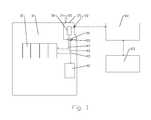
- FIG. 1is a schematic block diagram of an exemplary battery matrix and command module CWB assembly coupled to a power management system and load.
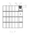
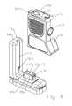
- FIG. 2is a schematic front view of a CWB assembly, with the command module interconnected with the battery matrix.
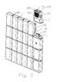
- FIG. 3is a schematic isometric view of the CWB assembly of FIG. 2 , with the command module aligned for interconnection with the battery matrix.
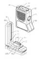
- FIG. 4is a close-up isometric view of the command module and battery matrix, showing interconnection features and the command module interface.
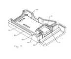
- FIG. 5is a schematic isometric view of a cut-away portion of the battery matrix housing and command module case, demonstrating exemplary retainer and receiver interconnection features.
- the inventorshave recognized that utilizing rechargeable CWBs may be cost prohibitive, particularly where the CWB is discharged only once and then abandoned, without being recharged/reused. Also, recharging apparatus may increase the users overall equipment load and may require an unacceptable charge time before re-use is possible, even if a suitable charging power source is available.
- FIGS. 1-5demonstrate an exemplary CWB assembly 1 with a battery matrix 5 comprising a plurality of battery cells 10 with a removable and reusable command module 15 .
- the command module 15includes a power switch 20 and capacity feedback 25 of the remaining battery electrical power delivery capacity (depletion).
- Processor circuitry 30 within the command moduleincludes a System Management Bus (SMB) for communication with devices coupled to the CWB via a power connection interface 35 and read/write functionality for an Electrically Erasable Programmable Read Only Memory (EEPROM), such as a serially programmable interface EEPROM.
- SMBSystem Management Bus
- EEPROMElectrically Erasable Programmable Read Only Memory
- the EEPROM 40integrated with the battery matrix 5 , may include read only registers for status and/or identifying data indicating:
- Registers within the processor circuitry 30which may be readable over the SMB by a device being powered by the CWB assembly 1 , may include:
- devices coupled to the power connection interface 70may also query and receive a power level indication of the attached battery matrix 5 , via SMB communication.
- the EEPROM 40is a serially programmable type, only a single conductor 45 is required for EEPROM 40 read/write communication.
- the command module 15energizes the line when data is high, and a capacitor in the EEPROM 40 provides stand-by power during a low data bit state. Therefore, the electrical connections between the command module 15 and the battery matrix 5 may comprise only three conductors: the power and ground contacts from the battery cell 10 and the EEPROM 40 read/write lead.
- the battery matrix 5is preferably provided environmentally sealed. Electrical connections between a battery matrix interface 50 of the command module 15 and a command module interface 55 of the battery matrix 5 may be configured for an environmentally sealed interconnection therebetween.
- the interconnections between the command module 15 and the attached power management system 60 and/or load 65 , via a power connection interface 70 of the command module,may also be environmentally sealed, for example utilizing a standard sealable 7 pin CWB power connection interface (such as GlenAir connector Part Number 807-348-01ZNU6-7SY) including conductors allocated for SMB data, SMB clock, and the Battery Matrix power and ground (routed from the command module interface 55 and battery matrix interface 50 , through the command module).
- a standard sealable 7 pin CWB power connection interfacesuch as GlenAir connector Part Number 807-348-01ZNU6-7SY
- additional conductors of the power connection interface 70 supporting interconnection with rechargeable type battery cellsmay be left unconnected and/or coupled to ground.
- alignment for mechanical interconnection and subsequent retention of the command module 15 upon the battery matrix 5may be via, for example, a retention slot 75 or the like of the battery matrix overbody 80 and a retention fin 85 of the command module case 90 that dovetail together to aligns the, for example, pins of the battery matrix interface 50 with sockets of the command module interface 55 .
- the retention fin 85interlocks with and travels to the bottom of the retention slot 75
- pins of the battery matrix interface 50may pierce a sealing membrane of the command module interface 55 before seating within the sockets.
- retention slot and retention finmay include retainer features 95 such as notches or tabs dimensioned to seat within corresponding receiver features 100 such as sockets or pockets, as best shown in FIG. 5 .
- Enhanced protection of the command module 15 and battery matrix 5 electrical interconnectionmay be obtained by providing a raised base 105 of the interconnection area extending from the battery matrix 5 , so that a cover portion 110 of the command module case 90 overlaps the raised base 105 , protecting both the pins of the battery matrix interface 50 prior to interconnection and extending the sealing surface surrounding the interconnection. Further retainer features 100 dimensioned to seat within corresponding receiver features 100 may also be applied to sidewalls of the raised base 105 .
- Capacity feedback 25 of the battery remaining power levelmay be, for example, via a plurality of light emitting diodes (LED) or the like. For example, where five out of five light emitting diodes are energized, a full power delivery capacity is represented, while a lower number of illuminated LEDs represents a corresponding reduction in available electrical power.
- the capacity feedback 25may be configured for activation for a predetermined time period upon actuation of the power switch 20 , before returning to a non-illuminated stand-by state.
- the command modulemonitors the current and voltage delivered by the battery matrix 5 .
- the command module 5calculates and writes an updated value to the Remaining Capacity register of the connected battery matrix EEPROM 40 .
- the command moduleis reusable, the battery matrix 5 of disposable cells with integral EEPROM 40 data storage enables a higher energy storage capacity and significantly reduced cost, compared to a rechargeable CWB. Because the battery matrix 5 are disposable, the users load may be reduced with each battery matrix 5 discharged and discarded, increasing user gear capacity and/or mobility.
- a single command module 15may be quickly exchanged between a supply of battery matrix 5 to verify remaining capacity, with the specific capacity of each battery matrix 15 accurately reflected in view of the data, specific to battery type and past usage, which remains with each respective battery matrix 15 even if disconnected/exchanged.
- the depletion curve characteristic of specific battery chemistriesmay be considered and incorporated into the capacity feedback 25 , instead of just current voltage of the battery cells, resulting in accurate and cost efficient capacity feedback 25 for a disposable battery matrix 15 .
- the electrical interconnection between the command module 15 and the battery matrix 5may be provided with as few as three electrical contacts, the interconnection may be cost efficiently provided with mechanically robust and securely environmentally sealed characteristics, improving the reliability of the resulting CWB assembly 1 mobile power delivery system.
Landscapes
- Engineering & Computer Science (AREA)
- Chemical & Material Sciences (AREA)
- Chemical Kinetics & Catalysis (AREA)
- Electrochemistry (AREA)
- General Chemical & Material Sciences (AREA)
- Manufacturing & Machinery (AREA)
- Theoretical Computer Science (AREA)
- Power Engineering (AREA)
- General Engineering & Computer Science (AREA)
- Physics & Mathematics (AREA)
- General Physics & Mathematics (AREA)
- Microelectronics & Electronic Packaging (AREA)
- Computer Hardware Design (AREA)
- Computing Systems (AREA)
- Charge And Discharge Circuits For Batteries Or The Like (AREA)
- Secondary Cells (AREA)
Abstract
Description
- Battery type
- Initial Voltage
- Cell Chemistry
- Design Capacity
- Serial Number
which may be written to the EEPROM40 duringbattery matrix 5 and/orEEPROM 40 manufacture. A further Remaining Capacity register may be read/writeable by thecommand module 15 based on the identifying data in view of current and voltage usage detected by thecommand module 15.
- Remaining Capacity Alarm
- Pack Voltage
- Pack Current
- Relative State of Charge
- Battery Status
- Design Capacity
- Design Voltage
- Manufacture Date
- Serial Number
| Table of Parts |
| 1 | |
| 5 | battery matrix |
| 10 | |
| 15 | |
| 20 | |
| 25 | |
| 30 | processor circuitry |
| 35 | |
| 40 | |
| 45 | |
| 50 | |
| 55 | |
| 60 | |
| 65 | |
| 70 | |
| 75 | |
| 80 | |
| 85 | |
| 90 | |
| 95 | |
| 100 | |
| 105 | raised base |
Claims (15)
Priority Applications (2)
| Application Number | Priority Date | Filing Date | Title |
|---|---|---|---|
| US14/550,184US9564761B2 (en) | 2014-11-21 | 2014-11-21 | Conformable wearable battery with removable command module |
| EP15194935.1AEP3024058A1 (en) | 2014-11-21 | 2015-11-17 | Conformable wearable battery with removable command module |
Applications Claiming Priority (1)
| Application Number | Priority Date | Filing Date | Title |
|---|---|---|---|
| US14/550,184US9564761B2 (en) | 2014-11-21 | 2014-11-21 | Conformable wearable battery with removable command module |
Publications (2)
| Publication Number | Publication Date |
|---|---|
| US20160233695A1 US20160233695A1 (en) | 2016-08-11 |
| US9564761B2true US9564761B2 (en) | 2017-02-07 |
Family
ID=54557317
Family Applications (1)
| Application Number | Title | Priority Date | Filing Date |
|---|---|---|---|
| US14/550,184Active2035-06-03US9564761B2 (en) | 2014-11-21 | 2014-11-21 | Conformable wearable battery with removable command module |
Country Status (2)
| Country | Link |
|---|---|
| US (1) | US9564761B2 (en) |
| EP (1) | EP3024058A1 (en) |
Cited By (18)
| Publication number | Priority date | Publication date | Assignee | Title |
|---|---|---|---|---|
| US10950913B1 (en) | 2020-09-30 | 2021-03-16 | Inventus Power, Inc. | Impact absorbing member for a conformal wearable battery |
| US10980116B1 (en) | 2020-09-30 | 2021-04-13 | Inventus Power, Inc. | Flexible battery matrix for a conformal wearable battery |
| US11064604B1 (en) | 2020-09-30 | 2021-07-13 | Inventus Power, Inc. | Flexible circuit board for a conformal wearable battery |
| US11081755B1 (en) | 2020-09-30 | 2021-08-03 | Inventus Power, Inc. | Housing for a conformal wearable battery |
| USD937222S1 (en) | 2020-10-30 | 2021-11-30 | Inventus Power, Inc. | Electrical contact |
| USD939433S1 (en) | 2020-10-30 | 2021-12-28 | Inventus Power, Inc. | Battery |
| US11251497B1 (en) | 2020-09-30 | 2022-02-15 | Inventus Power, Inc. | Conformal wearable battery |
| USD952863S1 (en) | 2020-10-08 | 2022-05-24 | Bloomer Health Tech Inc. | Monitoring garment |
| US11349174B2 (en) | 2020-09-30 | 2022-05-31 | Inventus Power, Inc. | Flexible battery matrix for a conformal wearable battery |
| US11394077B1 (en) | 2021-03-15 | 2022-07-19 | Inventus Power, Inc. | Conformal wearable battery |
| US11477885B2 (en) | 2020-09-30 | 2022-10-18 | Inventus Power, Inc. | Redundant trace fuse for a conformal wearable battery |
| US20230029518A1 (en)* | 2021-07-29 | 2023-02-02 | Bren-Tronics, Inc. | Portable secondary battery |
| US11581607B1 (en) | 2021-09-30 | 2023-02-14 | Inventus Power, Inc. | Thermal management for a conformal wearable battery |
| US11936070B2 (en) | 2020-07-10 | 2024-03-19 | Bloomer Health Tech Inc. | System and method for a wearable circuit |
| US12114426B2 (en) | 2020-09-30 | 2024-10-08 | Inventus Power, Inc. | Conformal wearable battery and system |
| US12151094B2 (en) | 2021-01-27 | 2024-11-26 | Neurostim Technologies Llc | Non-invasive nerve stimulator with battery management |
| EP4222807A4 (en)* | 2020-09-30 | 2025-02-12 | Inventus Power, Inc. | COMPLIANT WEARABLE BATTERY |
| US12429242B2 (en) | 2022-01-18 | 2025-09-30 | Computime Electronics (Shenzhen) Co. Ltd. | Thermostat with detachable dial control |
Families Citing this family (2)
| Publication number | Priority date | Publication date | Assignee | Title |
|---|---|---|---|---|
| JP7096102B2 (en)* | 2018-08-20 | 2022-07-05 | 本田技研工業株式会社 | Vehicle battery device |
| US10972144B2 (en)* | 2018-11-29 | 2021-04-06 | Harris Global Communications, Inc. | Communication systems with body worn plate design |
Citations (25)
| Publication number | Priority date | Publication date | Assignee | Title |
|---|---|---|---|---|
| US5075182A (en) | 1990-04-27 | 1991-12-24 | Weber Eugene W | Battery holder battery handle and battery indicator |
| US5188231A (en) | 1991-05-31 | 1993-02-23 | Duracell Inc. | Battery package with removable voltage indicator means |
| US5235967A (en)* | 1990-04-04 | 1993-08-17 | Arbisi Dominic S | Electro-magnetic impact massager |
| US5666006A (en)* | 1994-05-12 | 1997-09-09 | Apple Computer, Inc. | Circuit offering sequential discharge and simultaneous charge for a multiple battery system and method for charging multiple batteries |
| US5966079A (en) | 1997-02-19 | 1999-10-12 | Ranco Inc. Of Delaware | Visual indicator for identifying which of a plurality of dangerous condition warning devices has issued an audible low battery warning signal |
| US6027828A (en) | 1997-10-16 | 2000-02-22 | Advanced Mobile Solutions, Inc. | Modular stackable battery pack and accessories |
| US6222342B1 (en) | 2000-07-28 | 2001-04-24 | Snap-On Technologies, Inc. | Jump start battery pack and enclosure therefor |
| US6365297B1 (en)* | 1999-12-15 | 2002-04-02 | Delphi Technologies, Inc. | High-power bussing connection system for a battery pack |
| US6426606B1 (en) | 2000-10-10 | 2002-07-30 | Purkey Electrical Consulting | Apparatus for providing supplemental power to an electrical system and related methods |
| US6586850B1 (en)* | 2000-07-05 | 2003-07-01 | Koninklijke Philips Electronics N.V. | Device with multiple, concurrently-installed power molecules and method for controlling same |
| US6636015B1 (en) | 2002-05-09 | 2003-10-21 | Team Products International Inc. | Watertight portable auxiliary power source |
| US6977123B1 (en) | 1991-12-31 | 2005-12-20 | Strategic Energy Ltd. | Battery with strength indicator |
| US7161253B2 (en) | 2003-08-06 | 2007-01-09 | Briggs & Stratton Corporation | Portable power source |
| US7301303B1 (en) | 2004-08-16 | 2007-11-27 | International Specialty Services, Inc. | Portable battery jump start in a soft-sided carrying case |
| US7505856B2 (en) | 1999-04-08 | 2009-03-17 | Midtronics, Inc. | Battery test module |
| US20090082957A1 (en)* | 2007-09-20 | 2009-03-26 | Shai Agassi | Electric Vehicle Network |
| US20090291361A1 (en)* | 2008-05-20 | 2009-11-26 | Dino Scorziello | Wearable power supply for soldiers |
| US7759902B2 (en)* | 2005-01-19 | 2010-07-20 | Atmel Corporation | Single chip microcontroller including battery management and protection |
| USD623126S1 (en) | 2010-02-09 | 2010-09-07 | Continental Industries, Inc. | Battery, switch and voltage indicator device |
| US8058842B2 (en) | 2006-07-31 | 2011-11-15 | Hitachi Vehicle Energy, Ltd | Cell controller, battery module and power supply system |
| US8188876B1 (en) | 2009-05-29 | 2012-05-29 | Brunswick Corporation | Integrated battery level indicator, method and circuit for a trolling motor controller |
| US8203345B2 (en) | 2007-12-06 | 2012-06-19 | Midtronics, Inc. | Storage battery and battery tester |
| US8691416B1 (en) | 2010-02-16 | 2014-04-08 | The Boeing Company | Modular vehicular power system having a battery interface module and associated method |
| US8927137B2 (en)* | 2012-05-01 | 2015-01-06 | Microsun Technologies Llc | Fail safe damage resistant battery matrix |
| US8954610B2 (en)* | 2010-07-21 | 2015-02-10 | Dell Products L.P. | System-wide time synchronization across power management interfaces and sensor data |
Family Cites Families (3)
| Publication number | Priority date | Publication date | Assignee | Title |
|---|---|---|---|---|
| US7691502B2 (en)* | 2005-03-15 | 2010-04-06 | Jadoo Power Systems, Inc. | Modular fuel cell power system, and technique for controlling and/or operating same |
| US8361647B2 (en)* | 2010-03-19 | 2013-01-29 | GM Global Technology Operations LLC | Reversible battery assembly and tooling for automated high volume production |
| US20140141287A1 (en)* | 2012-11-19 | 2014-05-22 | Delphi Technologies, Inc. | Battery pack and battery control module |
- 2014
- 2014-11-21USUS14/550,184patent/US9564761B2/enactiveActive
- 2015
- 2015-11-17EPEP15194935.1Apatent/EP3024058A1/ennot_activeWithdrawn
Patent Citations (25)
| Publication number | Priority date | Publication date | Assignee | Title |
|---|---|---|---|---|
| US5235967A (en)* | 1990-04-04 | 1993-08-17 | Arbisi Dominic S | Electro-magnetic impact massager |
| US5075182A (en) | 1990-04-27 | 1991-12-24 | Weber Eugene W | Battery holder battery handle and battery indicator |
| US5188231A (en) | 1991-05-31 | 1993-02-23 | Duracell Inc. | Battery package with removable voltage indicator means |
| US6977123B1 (en) | 1991-12-31 | 2005-12-20 | Strategic Energy Ltd. | Battery with strength indicator |
| US5666006A (en)* | 1994-05-12 | 1997-09-09 | Apple Computer, Inc. | Circuit offering sequential discharge and simultaneous charge for a multiple battery system and method for charging multiple batteries |
| US5966079A (en) | 1997-02-19 | 1999-10-12 | Ranco Inc. Of Delaware | Visual indicator for identifying which of a plurality of dangerous condition warning devices has issued an audible low battery warning signal |
| US6027828A (en) | 1997-10-16 | 2000-02-22 | Advanced Mobile Solutions, Inc. | Modular stackable battery pack and accessories |
| US7505856B2 (en) | 1999-04-08 | 2009-03-17 | Midtronics, Inc. | Battery test module |
| US6365297B1 (en)* | 1999-12-15 | 2002-04-02 | Delphi Technologies, Inc. | High-power bussing connection system for a battery pack |
| US6586850B1 (en)* | 2000-07-05 | 2003-07-01 | Koninklijke Philips Electronics N.V. | Device with multiple, concurrently-installed power molecules and method for controlling same |
| US6222342B1 (en) | 2000-07-28 | 2001-04-24 | Snap-On Technologies, Inc. | Jump start battery pack and enclosure therefor |
| US6426606B1 (en) | 2000-10-10 | 2002-07-30 | Purkey Electrical Consulting | Apparatus for providing supplemental power to an electrical system and related methods |
| US6636015B1 (en) | 2002-05-09 | 2003-10-21 | Team Products International Inc. | Watertight portable auxiliary power source |
| US7161253B2 (en) | 2003-08-06 | 2007-01-09 | Briggs & Stratton Corporation | Portable power source |
| US7301303B1 (en) | 2004-08-16 | 2007-11-27 | International Specialty Services, Inc. | Portable battery jump start in a soft-sided carrying case |
| US7759902B2 (en)* | 2005-01-19 | 2010-07-20 | Atmel Corporation | Single chip microcontroller including battery management and protection |
| US8058842B2 (en) | 2006-07-31 | 2011-11-15 | Hitachi Vehicle Energy, Ltd | Cell controller, battery module and power supply system |
| US20090082957A1 (en)* | 2007-09-20 | 2009-03-26 | Shai Agassi | Electric Vehicle Network |
| US8203345B2 (en) | 2007-12-06 | 2012-06-19 | Midtronics, Inc. | Storage battery and battery tester |
| US20090291361A1 (en)* | 2008-05-20 | 2009-11-26 | Dino Scorziello | Wearable power supply for soldiers |
| US8188876B1 (en) | 2009-05-29 | 2012-05-29 | Brunswick Corporation | Integrated battery level indicator, method and circuit for a trolling motor controller |
| USD623126S1 (en) | 2010-02-09 | 2010-09-07 | Continental Industries, Inc. | Battery, switch and voltage indicator device |
| US8691416B1 (en) | 2010-02-16 | 2014-04-08 | The Boeing Company | Modular vehicular power system having a battery interface module and associated method |
| US8954610B2 (en)* | 2010-07-21 | 2015-02-10 | Dell Products L.P. | System-wide time synchronization across power management interfaces and sensor data |
| US8927137B2 (en)* | 2012-05-01 | 2015-01-06 | Microsun Technologies Llc | Fail safe damage resistant battery matrix |
Cited By (22)
| Publication number | Priority date | Publication date | Assignee | Title |
|---|---|---|---|---|
| US11936070B2 (en) | 2020-07-10 | 2024-03-19 | Bloomer Health Tech Inc. | System and method for a wearable circuit |
| US11251497B1 (en) | 2020-09-30 | 2022-02-15 | Inventus Power, Inc. | Conformal wearable battery |
| US11064604B1 (en) | 2020-09-30 | 2021-07-13 | Inventus Power, Inc. | Flexible circuit board for a conformal wearable battery |
| US11081755B1 (en) | 2020-09-30 | 2021-08-03 | Inventus Power, Inc. | Housing for a conformal wearable battery |
| EP4222807A4 (en)* | 2020-09-30 | 2025-02-12 | Inventus Power, Inc. | COMPLIANT WEARABLE BATTERY |
| US10950913B1 (en) | 2020-09-30 | 2021-03-16 | Inventus Power, Inc. | Impact absorbing member for a conformal wearable battery |
| US10980116B1 (en) | 2020-09-30 | 2021-04-13 | Inventus Power, Inc. | Flexible battery matrix for a conformal wearable battery |
| US11316227B2 (en) | 2020-09-30 | 2022-04-26 | Inventus Power, Inc. | Conformal wearable battery |
| US11349174B2 (en) | 2020-09-30 | 2022-05-31 | Inventus Power, Inc. | Flexible battery matrix for a conformal wearable battery |
| US12114426B2 (en) | 2020-09-30 | 2024-10-08 | Inventus Power, Inc. | Conformal wearable battery and system |
| US11477885B2 (en) | 2020-09-30 | 2022-10-18 | Inventus Power, Inc. | Redundant trace fuse for a conformal wearable battery |
| US12087956B2 (en) | 2020-09-30 | 2024-09-10 | Inventus Power, Inc. | Conformal wearable battery |
| USD952863S1 (en) | 2020-10-08 | 2022-05-24 | Bloomer Health Tech Inc. | Monitoring garment |
| USD1041663S1 (en) | 2020-10-08 | 2024-09-10 | Bloomer Health Tech Inc. | Monitoring garment |
| USD939433S1 (en) | 2020-10-30 | 2021-12-28 | Inventus Power, Inc. | Battery |
| USD986817S1 (en) | 2020-10-30 | 2023-05-23 | Inventus Power, Inc. | Battery |
| USD937222S1 (en) | 2020-10-30 | 2021-11-30 | Inventus Power, Inc. | Electrical contact |
| US12151094B2 (en) | 2021-01-27 | 2024-11-26 | Neurostim Technologies Llc | Non-invasive nerve stimulator with battery management |
| US11394077B1 (en) | 2021-03-15 | 2022-07-19 | Inventus Power, Inc. | Conformal wearable battery |
| US20230029518A1 (en)* | 2021-07-29 | 2023-02-02 | Bren-Tronics, Inc. | Portable secondary battery |
| US11581607B1 (en) | 2021-09-30 | 2023-02-14 | Inventus Power, Inc. | Thermal management for a conformal wearable battery |
| US12429242B2 (en) | 2022-01-18 | 2025-09-30 | Computime Electronics (Shenzhen) Co. Ltd. | Thermostat with detachable dial control |
Also Published As
| Publication number | Publication date |
|---|---|
| US20160233695A1 (en) | 2016-08-11 |
| EP3024058A1 (en) | 2016-05-25 |
Similar Documents
| Publication | Publication Date | Title |
|---|---|---|
| US9564761B2 (en) | Conformable wearable battery with removable command module | |
| US10141755B2 (en) | Multi-functional portable power charger | |
| US10250056B2 (en) | Multi-function external attachment and safety circuit for a portable power charger | |
| US8179092B2 (en) | Lithium-ion aircraft battery with automatically activated battery management system | |
| US7880431B2 (en) | Multiple interfaces for a rechargeable battery pack | |
| US20110093840A1 (en) | Patches for battery-interfacing devices and associated systems and methods | |
| US20160072329A1 (en) | Multi-functional high-capacity portable power charger | |
| US20150263553A1 (en) | Wearable / mountable mobile charging device | |
| CN113826271A (en) | Modular battery assembly for battery powered devices | |
| US20140098525A1 (en) | Incremental Portable Power Station System | |
| US20100320967A1 (en) | Rechargeable Battery Pack with Connecting Ports for Internal and External Charging/Output Operations | |
| US20250012863A1 (en) | State-of-charge indicator | |
| CA3024516C (en) | Power card and base | |
| US20130162210A1 (en) | Power supply system and rechargeable battery used in the system | |
| US9401609B2 (en) | Portable power transfer device | |
| US20190027718A1 (en) | Transportation Safe Battery | |
| US20100090645A1 (en) | Composite charging cradle for rechargeable battery | |
| US20250038552A1 (en) | Charger, charge indicator, and associated methods | |
| US10205199B2 (en) | Portable rechargeable power supply device | |
| CN204885691U (en) | Plug electric connector and cable assembly with same | |
| CN214674395U (en) | Pipeline periscope charger | |
| CN211377611U (en) | Handheld OTDR and power supply | |
| EP4073772B1 (en) | Modular system comprising a peripheral for an alarm system and a plurality of different power-packs for the peripheral | |
| KR101005348B1 (en) | Battery Charger for Lantern | |
| US12328009B2 (en) | Portable charging assembly |
Legal Events
| Date | Code | Title | Description |
|---|---|---|---|
| AS | Assignment | Owner name:PALLADIUM ENERGY, INC., ILLINOIS Free format text:ASSIGNMENT OF ASSIGNORS INTEREST;ASSIGNORS:HOPFER, ALBERT NICHOLAS, III;BATTS, WILLIAM MARK;HABEGGER, KENNETH;REEL/FRAME:034231/0507 Effective date:20141114 | |
| AS | Assignment | Owner name:GCI CAPITAL MARKETS LLC, AS ADMINISTRATIVE AGENT, Free format text:SECURITY INTEREST;ASSIGNOR:PALLADIUM ENERGY, INC.;REEL/FRAME:035536/0595 Effective date:20150430 | |
| STCF | Information on status: patent grant | Free format text:PATENTED CASE | |
| MAFP | Maintenance fee payment | Free format text:PAYMENT OF MAINTENANCE FEE, 4TH YEAR, LARGE ENTITY (ORIGINAL EVENT CODE: M1551); ENTITY STATUS OF PATENT OWNER: LARGE ENTITY Year of fee payment:4 | |
| AS | Assignment | Owner name:ALLY BANK, NEW YORK Free format text:PATENT SECURITY AGREEMENT;ASSIGNORS:INVENTUS POWER, INC.;PALLADIUM ENERGY GROUP, INC.;INVENTUS POWER (ILLINOIS ) LLC;AND OTHERS;REEL/FRAME:055752/0312 Effective date:20210329 | |
| AS | Assignment | Owner name:PENNANTPARK LOAN AGENCY SERVICING, LLC, NEW YORK Free format text:SECURITY INTEREST;ASSIGNORS:INVENTUS POWER, INC.;PALLADIUM ENERGY INC.;BATTERY LION ACQUISITION CORP. (NOW KNOWN AS PALLADIUM ENERGY GROUP, INC.);AND OTHERS;REEL/FRAME:055773/0479 Effective date:20210329 | |
| AS | Assignment | Owner name:PALLADIUM ENERGY GROUP, INC, ILLINOIS Free format text:RELEASE OF SECURITY INTEREST IN INTELLECTUAL PROPERTY COLLATERAL;ASSIGNOR:GOLUB CAPITAL MARKETS LLC (F/K/A GCI CAPITAL MARKETS LLC);REEL/FRAME:055889/0950 Effective date:20210329 Owner name:ICC-NEXERGY, INC. (N/K/A INVENTUS POWER, INC.), ILLINOIS Free format text:RELEASE OF SECURITY INTEREST IN INTELLECTUAL PROPERTY COLLATERAL;ASSIGNOR:GOLUB CAPITAL MARKETS LLC (F/K/A GCI CAPITAL MARKETS LLC);REEL/FRAME:055889/0950 Effective date:20210329 Owner name:PALLADIUM ENERGY OF ILLINOIS LLC (N/K/A INVENTUS POWER (ILLINOIS) LLC), ILLINOIS Free format text:RELEASE OF SECURITY INTEREST IN INTELLECTUAL PROPERTY COLLATERAL;ASSIGNOR:GOLUB CAPITAL MARKETS LLC (F/K/A GCI CAPITAL MARKETS LLC);REEL/FRAME:055889/0950 Effective date:20210329 Owner name:NEXERGY, INC. (N/K/A INVENTUS POWER (OHIO), INC.), ILLINOIS Free format text:RELEASE OF SECURITY INTEREST IN INTELLECTUAL PROPERTY COLLATERAL;ASSIGNOR:GOLUB CAPITAL MARKETS LLC (F/K/A GCI CAPITAL MARKETS LLC);REEL/FRAME:055889/0950 Effective date:20210329 Owner name:PALLADIUM ENERGY, INC. (N/K/A INVENTUS POWER (DELAWARE), INC.), ILLINOIS Free format text:RELEASE OF SECURITY INTEREST IN INTELLECTUAL PROPERTY COLLATERAL;ASSIGNOR:GOLUB CAPITAL MARKETS LLC (F/K/A GCI CAPITAL MARKETS LLC);REEL/FRAME:055889/0950 Effective date:20210329 | |
| AS | Assignment | Owner name:INVENTUS POWER (DELAWARE), INC., ILLINOIS Free format text:CHANGE OF NAME;ASSIGNOR:PALLADIUM ENERGY, INC.;REEL/FRAME:056757/0549 Effective date:20151124 | |
| AS | Assignment | Owner name:OAKTREE FUND ADMINISTRATION, LLC, AS ADMINISTRATIVE AGENT, CALIFORNIA Free format text:SECURITY INTEREST;ASSIGNORS:INVENTUS POWER, INC.;INVENTUS POWER (DELAWARE), INC.;REEL/FRAME:064181/0615 Effective date:20230630 | |
| AS | Assignment | Owner name:INVENTUS POWER (DELAWARE), INC., ILLINOIS Free format text:RELEASE BY SECURED PARTY;ASSIGNOR:ALLY BANK, AS ADMINISTRATIVE AGENT;REEL/FRAME:064158/0869 Effective date:20230630 Owner name:INVENTUS POWER (ILLINOIS) LLC, ILLINOIS Free format text:RELEASE BY SECURED PARTY;ASSIGNOR:ALLY BANK, AS ADMINISTRATIVE AGENT;REEL/FRAME:064158/0869 Effective date:20230630 Owner name:PALLADIUM ENERGY GROUP, INC., ILLINOIS Free format text:RELEASE BY SECURED PARTY;ASSIGNOR:ALLY BANK, AS ADMINISTRATIVE AGENT;REEL/FRAME:064158/0869 Effective date:20230630 Owner name:INVENTUS POWER, INC., ILLINOIS Free format text:RELEASE BY SECURED PARTY;ASSIGNOR:ALLY BANK, AS ADMINISTRATIVE AGENT;REEL/FRAME:064158/0869 Effective date:20230630 | |
| AS | Assignment | Owner name:MICROSUN TECHNOLOGIES, LLC (NOW KNOWN AS INVENTUS POWER (ILLINOIS) LLC), ILLINOIS Free format text:RELEASE BY SECURED PARTY;ASSIGNOR:PENNANTPARK LOAN AGENCY SERVICING, LLC;REEL/FRAME:064209/0710 Effective date:20230630 Owner name:BATTERY LION ACQUISITION CORP. (NOW KNOWN AS PALLADIUM ENERGY GROUP, INC., ILLINOIS Free format text:RELEASE BY SECURED PARTY;ASSIGNOR:PENNANTPARK LOAN AGENCY SERVICING, LLC;REEL/FRAME:064209/0710 Effective date:20230630 Owner name:PALLADIUM ENERGY INC. (NOW KNOWN AS INVENTUS POWER (DELAWARE), INC.), ILLINOIS Free format text:RELEASE BY SECURED PARTY;ASSIGNOR:PENNANTPARK LOAN AGENCY SERVICING, LLC;REEL/FRAME:064209/0710 Effective date:20230630 Owner name:INVENTUS POWER, INC., ILLINOIS Free format text:RELEASE BY SECURED PARTY;ASSIGNOR:PENNANTPARK LOAN AGENCY SERVICING, LLC;REEL/FRAME:064209/0710 Effective date:20230630 | |
| MAFP | Maintenance fee payment | Free format text:PAYMENT OF MAINTENANCE FEE, 8TH YEAR, LARGE ENTITY (ORIGINAL EVENT CODE: M1552); ENTITY STATUS OF PATENT OWNER: LARGE ENTITY Year of fee payment:8 |