US9562921B2 - Immunodiagnostic test element having weakened foil layer - Google Patents
Immunodiagnostic test element having weakened foil layerDownload PDFInfo
- Publication number
- US9562921B2 US9562921B2US12/054,790US5479008AUS9562921B2US 9562921 B2US9562921 B2US 9562921B2US 5479008 AUS5479008 AUS 5479008AUS 9562921 B2US9562921 B2US 9562921B2
- Authority
- US
- United States
- Prior art keywords
- test
- wrap
- test column
- column
- tip member
- Prior art date
- Legal status (The legal status is an assumption and is not a legal conclusion. Google has not performed a legal analysis and makes no representation as to the accuracy of the status listed.)
- Active, expires
Links
Images


Classifications
- G—PHYSICS
- G01—MEASURING; TESTING
- G01N—INVESTIGATING OR ANALYSING MATERIALS BY DETERMINING THEIR CHEMICAL OR PHYSICAL PROPERTIES
- G01N35/00—Automatic analysis not limited to methods or materials provided for in any single one of groups G01N1/00 - G01N33/00; Handling materials therefor
- G01N35/10—Devices for transferring samples or any liquids to, in, or from, the analysis apparatus, e.g. suction devices, injection devices
- G01N35/1079—Devices for transferring samples or any liquids to, in, or from, the analysis apparatus, e.g. suction devices, injection devices with means for piercing stoppers or septums
- B—PERFORMING OPERATIONS; TRANSPORTING
- B01—PHYSICAL OR CHEMICAL PROCESSES OR APPARATUS IN GENERAL
- B01L—CHEMICAL OR PHYSICAL LABORATORY APPARATUS FOR GENERAL USE
- B01L3/00—Containers or dishes for laboratory use, e.g. laboratory glassware; Droppers
- B01L3/50—Containers for the purpose of retaining a material to be analysed, e.g. test tubes
- B01L3/502—Containers for the purpose of retaining a material to be analysed, e.g. test tubes with fluid transport, e.g. in multi-compartment structures
- B01L3/5025—Containers for the purpose of retaining a material to be analysed, e.g. test tubes with fluid transport, e.g. in multi-compartment structures for parallel transport of multiple samples
- B—PERFORMING OPERATIONS; TRANSPORTING
- B01—PHYSICAL OR CHEMICAL PROCESSES OR APPARATUS IN GENERAL
- B01L—CHEMICAL OR PHYSICAL LABORATORY APPARATUS FOR GENERAL USE
- B01L2200/00—Solutions for specific problems relating to chemical or physical laboratory apparatus
- B01L2200/02—Adapting objects or devices to another
- B01L2200/026—Fluid interfacing between devices or objects, e.g. connectors, inlet details
- B—PERFORMING OPERATIONS; TRANSPORTING
- B01—PHYSICAL OR CHEMICAL PROCESSES OR APPARATUS IN GENERAL
- B01L—CHEMICAL OR PHYSICAL LABORATORY APPARATUS FOR GENERAL USE
- B01L2300/00—Additional constructional details
- B01L2300/04—Closures and closing means
- B01L2300/041—Connecting closures to device or container
- B01L2300/044—Connecting closures to device or container pierceable, e.g. films, membranes
- B—PERFORMING OPERATIONS; TRANSPORTING
- B01—PHYSICAL OR CHEMICAL PROCESSES OR APPARATUS IN GENERAL
- B01L—CHEMICAL OR PHYSICAL LABORATORY APPARATUS FOR GENERAL USE
- B01L2400/00—Moving or stopping fluids
- B01L2400/04—Moving fluids with specific forces or mechanical means
- B01L2400/0403—Moving fluids with specific forces or mechanical means specific forces
- B01L2400/0409—Moving fluids with specific forces or mechanical means specific forces centrifugal forces
- B—PERFORMING OPERATIONS; TRANSPORTING
- B01—PHYSICAL OR CHEMICAL PROCESSES OR APPARATUS IN GENERAL
- B01L—CHEMICAL OR PHYSICAL LABORATORY APPARATUS FOR GENERAL USE
- B01L2400/00—Moving or stopping fluids
- B01L2400/06—Valves, specific forms thereof
- B01L2400/0677—Valves, specific forms thereof phase change valves; Meltable, freezing, dissolvable plugs; Destructible barriers
- B01L2400/0683—Valves, specific forms thereof phase change valves; Meltable, freezing, dissolvable plugs; Destructible barriers mechanically breaking a wall or membrane within a channel or chamber
- B—PERFORMING OPERATIONS; TRANSPORTING
- B01—PHYSICAL OR CHEMICAL PROCESSES OR APPARATUS IN GENERAL
- B01L—CHEMICAL OR PHYSICAL LABORATORY APPARATUS FOR GENERAL USE
- B01L3/00—Containers or dishes for laboratory use, e.g. laboratory glassware; Droppers
- B01L3/50—Containers for the purpose of retaining a material to be analysed, e.g. test tubes
- B01L3/502—Containers for the purpose of retaining a material to be analysed, e.g. test tubes with fluid transport, e.g. in multi-compartment structures
- B01L3/5021—Test tubes specially adapted for centrifugation purposes
- Y—GENERAL TAGGING OF NEW TECHNOLOGICAL DEVELOPMENTS; GENERAL TAGGING OF CROSS-SECTIONAL TECHNOLOGIES SPANNING OVER SEVERAL SECTIONS OF THE IPC; TECHNICAL SUBJECTS COVERED BY FORMER USPC CROSS-REFERENCE ART COLLECTIONS [XRACs] AND DIGESTS
- Y10—TECHNICAL SUBJECTS COVERED BY FORMER USPC
- Y10T—TECHNICAL SUBJECTS COVERED BY FORMER US CLASSIFICATION
- Y10T436/00—Chemistry: analytical and immunological testing
- Y10T436/11—Automated chemical analysis
Definitions
- the applicationrelates to the field of immunodiagnostic testing and in particular to an immunological test element having at least one test chamber and covered by a pierceable foil layer.
- the foil layeris defined by at least one weakened portion that permits puncture, such as by a fluid dispensing and aspirating element, in order to facilitate access to the contents of the test chamber.
- Immunological agglutination reactionsare presently used for identifying various kinds of blood types as well as for detecting various kinds of antibodies and antigens in blood samples and other aqueous solutions.
- a sample of red blood cellsis mixed with serum or plasma in either test tubes or microplates, wherein the mixture is incubated and then centrifuged.
- Various reactionsthen occur or do not occur depending on, for example, the blood types of the red blood cells or whether certain antibodies are present within the blood sample.
- These reactionsmanifest themselves as clumps of cells or as particles with antigens or antibodies on their surfaces, referred to as agglutinates.
- agglutination test methodAs described, for example, in U.S. Pat. No. 5,512,432 to LaPierre et al., and rather than using microplates or test tubes, another form of agglutination test method has been developed and successfully commercialized. According to this method, gel or glass bead microparticles are contained within a small column, referred to as a microcolumn or a microtube. A reagent, such as anti-A, is dispensed in a diluent in the microcolumn and test red blood cells are placed in the reaction chamber above the column. The column, which is typically one of a plurality of columns formed in a transparent card or cassette, is then centrifuged.
- a reagentsuch as anti-A
- the centrifugationaccelerates the reaction, if any, between the red blood cells and the reagent, and also urges any cells toward the bottom of the column.
- the glass beads or the gel materialacts as a filter, and resists or impedes downward movement of the particles in the column.
- the nature and distribution of the particles in the microcolumnprovides a visual indication of whether any agglutination reaction has occurred, and if such a reaction has occurred, the strength of the reaction based on the relative position of the agglutinates in the column. If no agglutination reaction has occurred, then all or virtually all of the red blood cells in the microtube will pass downward during the centrifugation procedure, to the bottom of the column in the form of a pellet.
- red blood cellsConversely and if there is a strong reaction between the reagent and the red blood cells, then virtually all of the red blood cells will agglutinate, and large groupings will form at the top of the microtube above the gel or bead matrix in that the matrix is sized not to let these clumps pass through. Reactions falling between these latter two extremes are possible in which some but not all of the red blood cells will have agglutinated. The percentage of red blood cells that agglutinate and the size of the agglutinated particles each have a relationship with the strength of the reaction.
- the microtubeis visually examined by either a human operator or by machine vision and the reaction between the red blood cells and the reagent is then classified.
- the reactionis classified as being either positive or negative, and if positive, the reaction is further classified into one of four classes depending on the strength of the reaction.
- test elementsthat employ a plurality of microtubes for purposes of creating agglutination reactions as described above for purposes of blood grouping, blood typing, antigen or antibody detection and other related applications and uses.
- These test elementscommonly include a planar substrate that supports a plurality of transparent columns or microtubes, each of the columns containing a quantity of an inert material, such as a gel material or a plurality of glass beads, respectively, that is coated with an antigen or antibody or material or is provided with a carrier-bound antibody or antigen, each of the foregoing being provided by the manufacturer.
- a pierceable wrapcompletes the assembly of the test element, the wrap, which may be, for example, in the form of an adhesively or otherwise-attached foil wrap, covering the top side of the test element, in order to cover the contents of each column.
- the wrapOnce pierced, aliquots of patient sample and possibly reagents (e.g., if reagents are not first added by the manufacturer or additional reagents, depending on the test) can be added to the columns, either manually or using automated apparatus.
- test elementthus containing patient sample (e.g., red blood cells and sera) is then incubated and following incubation, the test element is spun down by centrifugation, as noted above, in order to accelerate an agglutination reaction that can be graded either based on the position of agglutinates within each transparent column of the test element or cassette or due to a lack of agglutination based on the cells settling at the bottom of the test column.
- patient samplee.g., red blood cells and sera
- each of these test elementsinclude a foil wrap disposed at the top of the card or cassette covering the columns wherein the wrap can be pierced prior to the dispense of the patient sample, reagents, or other material into at least one microtube of the test element.
- the foil wrapforms a seal relative to the contents of the columns to prevent contamination and also prevents the contents of the columns from drying out or degrading.
- a number of automated or semi-automated apparatussuch as those manufactured by Ortho-Clinical Diagnostics, Inc., DiaMed A.G., and Grifols, are known that utilize plurality of gel cards or bead cassettes, such as those manufactured and sold by Micro-Typing Systems, Inc., DiaMed A.G., and BioRad, among others.
- these apparatusemploy separate assemblies to accomplish the piercing function.
- a pipette assembly probeis used to directly puncture the foil wrap. Using the metering probe for puncture wherein contact is made with the contents of the test columns means that this probe must undergo a separate washing operation following the piercing step before use thereof can be resumed to avoid contamination.
- a piercing assemblyhaving a plurality of dedicated puncture elements used to puncture the seals for each of the test chambers of a test element.
- This dedicated apparatusalso adds a level of complexity, including an increase to the size of the overall footprint of the apparatus.
- the latter assemblyalso requires washing operations of the puncture elements themselves prior to any re-use thereof.
- the latter puncture assemblyoperates with only a fixed number of configurations wherein typically all of the test columns of the test card are punctured, even for tests in which certain columns are not necessarily required. Still other test elements are accessed by removal of the entire foil strip prior to processing.
- an immunodiagnostic test elementcomprising a substrate, at least one test column supported by said substrate, each said test column containing a test material, and a wrap adhesively or otherwise-attached wrap covering the top of said at least one test element, such as, for example, an adhesively-attached foil wrap wherein said foil wrap includes a weakened portion directly above each said at least one test column, each said weakened portion being formed by pre-stressing said portion, but not to the point of puncturing the foil wrap.
- the foil wrapis drastically weakened locally, thereby enabling each pre-stressed portion to be easily punctured, for example, using a disposable fluid aspirating dispensing member, such as a metering tip.
- the pre-stressed portionsare also locally deformed and assume a bowl-like concave shape.
- the pre-stressingcan be performed on the wrap prior to covering of the test element with the wrap.
- a method for using a test element to enable the test element to be used in conjunction with a disposable metering elementcomprising the steps of: providing a test card, said test card including a support member, at least one test column attached to or integral to said support member and a wrap, such as, for example, a foil wrap, covering the top side of said at least one test card; and prestressing at least one portion of the foil wrap directly above the contents of said at least one test column, but without puncturing the foil wrap, wherein said pre-stressing step creates a weakened portion.
- the pre-stressing stepcan be performed on the wrap prior to the covering of the test element with the wrap.
- the above methodadditionally includes the step of performing the pre-stressing step prior to testing said test element, said prestressing step being performed within an immunodiagnostic testing apparatus by means of at least one of a metering probe and a dedicated mechanism.
- the pre-stressed portioncauses local deformation of the foil wrap, creating an indentation that is inwardly curved, forming a substantially bowl-like appearance.
- This portioncan then be easily punctured by a separate element.
- a disposable fluid aspirating/dispensing elementcan be used in lieu of a metering probe to puncture the weakened foil wrap. This disposable element can be used in order to puncture the foil seal and dispense patient sample in a single operation.
- One advantage that is realized by the present inventionis that contamination within an automated immunodiagnostic testing apparatus is markedly reduced.
- the mechanism that creates the weakened pre-stressed portion of the foil wrapdoes not require a separate washing operation in that this mechanism does not contact any of the contents of the test element.
- the geometry of the weakened foil wrap portionprovides a bowl-like feature that reduces the incidence of splashing or drainage of sample or reagent into adjacent wells or columns.
- the herein described apparatus and methodprovides considerable cost savings as well as considerable improvements in throughput when used in conjunction with an automated apparatus.
- the number of punctures made to any given test elementcan easily be varied wherein all or only some of the test columns can be accessed. Therefore, the system is not limited to a fixed number of configurations, thereby providing increased versatility over prior systems.
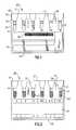
- FIGS. 1 and 2are front views of a pair of prior art immunodiagnostic test elements
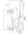
- FIG. 3is a partial top perspective view of a prior art immunodiagnostic testing apparatus
- FIG. 4is a simplified front view of the testing apparatus of FIG. 3 ;
- FIG. 5is a partial side elevational view of the piercing assembly of the prior art immunodiagnostic testing apparatus of FIG. 3 ;
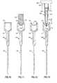
- FIGS. 6 and 7depict top perspective and top plan views of a test element made in accordance with one embodiment prior to piercing of the pre-weakened portions of the foil wrap;
- FIGS. 8 and 9depict top perspective and top plan views of the test element of FIGS. 6 and 7 following piercing of the pre-weakened portions
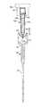
- FIGS. 10-13depict side views of a test column of the immunodiagnostic test element of FIGS. 8 and 9 , sequentially illustrating a process of adding a weakened feature to the foil wrap, as well as a subsequent punching step in accordance with an embodiment to permit access to the contents of the test column by means of a metering tip member.
- an immunodiagnostic test elementin this case a gel card or bead cassette. It will be readily apparent to those of skill in the field that the inventive concepts described herein also relate to literally any other form of immunodiagnostic test element that includes at least one test chamber and a wrap, such as, for example, a foil wrap, which covers the at least one test chamber.
- a wrapsuch as, for example, a foil wrap
- FIGS. 1 and 2illustrate a pair of prior art immunodiagnostic test elements. More specifically, FIG. 1 depicts a gel card 20 while FIG. 2 depicts a bead cassette 30 .
- Each of the test elements 20 , 30include a number of common structural features. That is, each test element 20 , 30 commonly includes a support member 26 in the form of a planar substrate having a top side 27 and a bottom side 28 , wherein the substrate supports a plurality of microtubes or test columns 34 .
- the microtubes 34are made from a transparent material and are further defined by an upper portion 37 having an open top opening, an inwardly tapering transitional portion 39 and a lower portion 41 .
- a predetermined quantity of an inert material 38 , 42is contained within the lower portion 41 of each test column 34 , as typically provided by a manufacturer.
- the inert material 38is a gel material, such as Sephacryl or other suitable material
- the inert material 42is defined by a matrix of glass or other beads.
- Each of the inert material 38 , 42is typically defined by a plurality of particles having a diameter of between about 10 and 100 microns.
- each microtube 34is further coated with an antibody or provided with a carrier-bound antigen or antibody, such as anti-A, also typically provided by the manufacturer, thereby defining an aqueous medium.
- a pierceable foil wrap 50 provided at the top side 27 of each test element 20 , 30covers that seals the microtubes 34 in order to protect the contents and also to prevent dehydration or degrading thereof.
- the foregoing immunodiagnostic test elements 20 , 30can be used in an automated testing apparatus 60 , such as that shown in FIGS. 3-5 .
- the testing apparatus 60retains a number of components including a reagent and sample supply 70 , an incubator station 80 , a centrifuge 90 , an analysis station 100 , and a drawer assembly 190 , each shown in FIG. 3 .
- the sample and reagent supply 70 of this apparatus 60includes a sample rack 74 as well as a reagent rack 78 , each of which contain bottles or vials of patient sample and reagent, respectively.
- the supplyis constructed as a rotor that is rotatable about a center axis by means of a drive mechanism that includes a motor 77 , FIG. 4 , wherein a bar code reader 79 is further provided in relation to the supply 70 as well as a tube hold-down assembly 76 disposed over a portion thereof.
- the incubator station 80includes a cassette rack 82 that further includes respective first and second sections 84 , 86 , as well as a drive mechanism that includes a motor 88 .
- the centrifuge 90includes a rotor 94 and a motor 98 .
- the analysis station 100includes holding means 102 , illumination means 104 , an imaging subsystem 106 , a processing subsystem 108 , a transport subsystem 110 , a storage rack 115 , a bar code reader 112 , and a waste receptacle 116 .
- the drawer assembly 190includes a drawer 192 , FIG. 4 , a slide tray 194 , FIG. 4 , a motor 195 , a sensor bar 196 , a bar code reader 198 and a holding area 197 .
- a transport assembly 130 , FIG. 4 , of the testing apparatus 60includes a robot arm 134 , FIG. 4 , and a gripper 138 , FIG. 4 .
- a pipette assembly 120FIG.
- FIG. 4includes a pipette 124 , FIG. 4 , attached to a robot arm 128 , FIG. 4 , this assembly further including shallow and deep wash areas 122 , 125 , as well as cell dilution packs 127 .
- test elements 30are initially supported within the drawer 192 and are read by the bar code reader 198 . Assuming the read is successful, the test elements 30 are loaded by means of the transport assembly 130 and the gripper 138 into the cassette rack 82 of the incubator 80 .
- a piercing assembly 140FIG. 5 , is disposed above the first and second sections 84 , 86 of the cassette rack 82 of the incubator 80 and includes a support subassembly 144 that includes a slide support 145 , FIG. 5 , having a plurality of puncture needles 146 , FIG.
- the incubator 80as driven by the motor 88 , is used to incubate patient sample added to each of the test columns from one of the vials of the sample rack 65 , the incubator further including an assembly 76 that holds down the sample and reagent vials.
- the pipette 124 of the pipette assembly 120is used to aspirate sample from the sample rack 65 , while the piercing assembly 140 , FIG. 5 , is used to puncture each of the microtubes of the then-incubated test elements 30 . Once the puncturing step has been completed as shown by the test elements shown in FIGS.
- the pipette 124can then be used to dispense a predetermined quantity of patient sample (and possibly additional reagents) from the sample and reagent supply 70 into each of the test columns 34 , FIG. 2 , wherein the mixture can be suitably incubated.
- test elements 30are removed from the incubator 80 by means of the transport assembly 130 to the centrifuge 90 wherein the test elements 30 are then spun down, thereby accelerating an agglutination reaction as red blood cells are clumped together in the presence of coated reagents.
- the plurality of beads disposed in each column of the test element 30includes particles having diameters ranging between about 10 and 100 microns, providing a matrix for the red blood cells, but not the heavier formed agglutinates to pass through by filtering.
- the resulting reactioncan be imaged within the analysis station 100 of the apparatus 60 by means of the illumination assembly 104 and imaging subsystem 106 , the latter being connected to the processing subsystem 108 having machine vision for grading of the reaction. Additional details concerning the foregoing testing apparatus 60 are provided in commonly-assigned U.S. Pat. No. 5,578,269 to Yaremko et al., the entire contents of which are herein incorporated by reference.
- Test element 150includes a planar substrate 26 having a top side 27 and an opposing bottom side 28 wherein the substrate supports a plurality of transparent microtubes 34 .
- the substrate 26 and microtubes 34are preferably each made from a lightweight durable plastic material, such as polystyrene, polyamide, acrylic or other suitable material.
- Each of the microtubes 34is defined by an open top opening formed in an upper portion 37 having a diameter that is substantially larger than that of a lower portion 41 , the upper and lower portions being linked by an inwardly transitioning transitional portion 39 to form a test chamber that contains a quantity of an inert material, in this instance, a matrix of glass beads having a diameter between about 10 and 100 microns.
- a foil wrap 50is adhesively or otherwise attached to the top side 27 of the test element 110 .
- test element 150 and specifically the foil wrap 50is further defined by a plurality of weakened portions 154 formed therein.
- Each of the weakened portions 154are formed in a section that is disposed directly above the upper portion 37 of each transparent microtube 34 .
- test element 150is shown, depicting sequentially one technique for forming the above-noted weakened or pre-stressed portions 154 .
- the test element 150has at least one microtube 34 supported by the planar substrate 26 that contains a predetermined quantity of an inert test material such as gel material or glass beads (not shown in these views).
- a foil seal 50is secured onto the top side of the test element 150 , preferably by adhesive or other bonding means.
- test element 110is not shown as supported, but would be supported, for example, within an incubator 68 , FIG. 3 , as described in previously cross-referenced and commonly-assigned U.S. Pat. No. 5,578,269 to Yaremko et al., in a known manner.
- a punch 170 or other elementis used to locally prestress the foil layer 50 immediately above each microtube 34 of the test element 150 .
- the punch 170does not puncture the layer 50 , but rather merely locally deforms a portion 154 of the foil layer 50 inwardly towards the interior of the column given that there is no resisting surface acting against the force of the punch.
- the weakened portion 154assumes a inwardly-curved bowl-like shape.
- a shaped punch head 176 having a concave configurationis used to perform this operation.
- other apparatuscould be used for purposes of creating each pre-weakened portion 154 .
- the metering probe of the automated apparatuscould alternatively be used in terms of this operation.
- the punch 170is then raised and moved out of position, leaving the test element 150 as shown in FIG. 12 .
- the weakened portion 154 of the foil layer 50can actually be punctured to permit access to the contents of the test chamber(s).
- puncturecan be done using a metering tip member, such as a VitrosTM metering element manufactured by Ortho-Clinical Diagnostics, Inc.
- the metering tip member 180is disposable, being made from a plastic material and defined by a tapering cylindrical body 182 .
- the tip member 180is further defined by an upper tip opening 184 , a lower tip opening 186 and an interior 188 .
- the metering tip member 180is shown as attached to a metering mechanism 189 (shown diagrammatically in FIG.
- the tip member 180retains a quantity of patient sample 183 or other fluid within its interior 188 that is aspirated from a supply such as the sample and reagent supply 70 , FIG. 3 , within the testing apparatus 60 , FIG. 3 .
- the metering mechanism 189includes a stepper motor that enables the proboscis and attached tip member 180 to also be moved vertically in the direction of arrow 181 , enabling the tip member to be moved into a position to permit the tip member to be lowered in order to puncture the weakened portion 154 of the foil layer 50 and access the interior of each microtube 34 of the test element 150 as shown in FIG. 13 .
- the metering tip member 180by already containing a quantity of patient sample 183 from the patient sample supply 70 , FIG. 3 , of the apparatus 60 , FIG. 3 , can actually perform both the puncturing and dispensing steps in a continuous operation, thereby significantly improving throughput in a suitably equipped apparatus.
- the inwardly curved shape of each weakened portion 154provides another advantage by reducing the incidence of splashing or cross-contamination between adjacent column.
- test element 150is shown following puncture of the pre-weakened portions 154 by means of the metering tip member 180 , FIG. 13 , wherein each of the multiple punctures as shown are highly repeatable in terms of their geometry and size. This repeatability reduces the chance of spillage or cross-contamination between adjacent columns of the test element 150 .
- the tip member 180can be withdrawn from the test element 150 and discarded, such as through a drop chute (not shown) or other disposal means. Similar operations can be performed for each of the remaining microtubes 34 of the test element 150 prior to test wherein each of the test elements have been positioned in an incubator assembly 80 , FIG. 3 , of the automated apparatus 60 , FIG. 3 .
- the patient samplecan be incubated and then the test element can be moved to the centrifuge 90 , FIG. 3 , of the apparatus 60 , FIG. 3 , wherein the test element 150 can be spun down in advance of a subsequent detection of an agglutination reaction, if any, between the bound matrix and the red blood cells of the sample.
- Exemplary operations of this typeare described in commonly-assigned U.S. Pat. No. 5,911,000 to Shen, the contents of which are herein incorporated by reference in their entirety.
Landscapes
- Health & Medical Sciences (AREA)
- Chemical & Material Sciences (AREA)
- Analytical Chemistry (AREA)
- General Health & Medical Sciences (AREA)
- Chemical Kinetics & Catalysis (AREA)
- Hematology (AREA)
- Clinical Laboratory Science (AREA)
- Biochemistry (AREA)
- Life Sciences & Earth Sciences (AREA)
- General Physics & Mathematics (AREA)
- Immunology (AREA)
- Pathology (AREA)
- Physics & Mathematics (AREA)
- Automatic Analysis And Handling Materials Therefor (AREA)
- Investigating Or Analysing Biological Materials (AREA)
- Measurement Of The Respiration, Hearing Ability, Form, And Blood Characteristics Of Living Organisms (AREA)
Abstract
Description
- 20 gel card
- 26 support member (planar substrate)
- 27 top side
- 28 bottom side
- 30 bead cassette
- 34 microtubes (test column)
- 37 upper portion
- 38 gel material
- 39 inwardly tapering transitional portion
- 41 lower portion
- 42 bead matrix
- 50 foil wrap
- 54 label
- 55 bar code
- 58 panel
- 60 automated testing apparatus
- 64 frame
- 70 sample and reagent supply
- 74 sample rack
- 76 tube hold-down assembly
- 77 drive means
- 78 reagentrack
- 79 bar code reader
- 80 incubator station
- 82 cassette rack
- 84 first section
- 86 second section
- 88 motor
- 90 centrifuge
- 94 rotor
- 98 motor
- 100 analysis station
- 102 holding means
- 104 illumination means
- 106 imaging subsystem
- 108 processing subsystem
- 110 transport subsystem
- 112 bar code reader
- 115 storage rack
- 116 waste receptacle
- 120 pipette assembly
- 122 shallow wash area
- 124 pipette
- 125 deep wash area
- 127 cell dilution racks
- 128 robot arm
- 130 transport assembly
- 134 robot arm
- 138 gripper
- 140 piercing assembly
- 144 support subassembly
- 146 piercing needles
- 150 test element
- 154 weakened or pre-stressed portions
- 170 punch
- 176 punch head
- 180 metering tip member
- 181 direction
- 182 cylindrical body
- 183 sample
- 184 upper tip opening
- 186 lower tip opening
- 188 interior
- 189 metering mechanism
- 190 drawer assembly
- 192 drawer
- 194 slide tray
- 195 motor
- 196 sensor bar
- 197 holding area
- 198 bar code reader
Claims (7)
Priority Applications (10)
| Application Number | Priority Date | Filing Date | Title |
|---|---|---|---|
| US12/054,790US9562921B2 (en) | 2008-03-25 | 2008-03-25 | Immunodiagnostic test element having weakened foil layer |
| BRPI0910061ABRPI0910061A2 (en) | 2008-03-25 | 2009-03-13 | immunodiagnostic test element with weakened leaf layer |
| PCT/US2009/037051WO2009120516A1 (en) | 2008-03-25 | 2009-03-13 | Immunodiagnostic test element having weakened foil layer |
| EP09724343.0AEP2257820B1 (en) | 2008-03-25 | 2009-03-13 | Immunodiagnostic test element, test device and test method having a pierceable cover consisting of a weakened foil layer |
| CN200980119020.8ACN102047125B (en) | 2008-03-25 | 2009-03-13 | Immunodiagnostic test element with weakened foil layer |
| RU2010143372/15ARU2485497C2 (en) | 2008-03-25 | 2009-03-13 | Immune monitoring test element with weakened foil layer |
| JP2011501898AJP5384613B2 (en) | 2008-03-25 | 2009-03-13 | Immunodiagnostic test element with weakened foil layer |
| CA2719430ACA2719430C (en) | 2008-03-25 | 2009-03-13 | Immunodiagnostic test element having weakened foil layer |
| JP2013167391AJP5922066B2 (en) | 2008-03-25 | 2013-08-12 | Immunodiagnostic test element with weakened foil layer |
| US15/420,559US10018645B2 (en) | 2008-03-25 | 2017-01-31 | Immunodiagnostic test element having weakened foil layer |
Applications Claiming Priority (1)
| Application Number | Priority Date | Filing Date | Title |
|---|---|---|---|
| US12/054,790US9562921B2 (en) | 2008-03-25 | 2008-03-25 | Immunodiagnostic test element having weakened foil layer |
Related Child Applications (1)
| Application Number | Title | Priority Date | Filing Date |
|---|---|---|---|
| US15/420,559DivisionUS10018645B2 (en) | 2008-03-25 | 2017-01-31 | Immunodiagnostic test element having weakened foil layer |
Publications (2)
| Publication Number | Publication Date |
|---|---|
| US20090246877A1 US20090246877A1 (en) | 2009-10-01 |
| US9562921B2true US9562921B2 (en) | 2017-02-07 |
Family
ID=40677570
Family Applications (2)
| Application Number | Title | Priority Date | Filing Date |
|---|---|---|---|
| US12/054,790Active2028-05-16US9562921B2 (en) | 2008-03-25 | 2008-03-25 | Immunodiagnostic test element having weakened foil layer |
| US15/420,559ActiveUS10018645B2 (en) | 2008-03-25 | 2017-01-31 | Immunodiagnostic test element having weakened foil layer |
Family Applications After (1)
| Application Number | Title | Priority Date | Filing Date |
|---|---|---|---|
| US15/420,559ActiveUS10018645B2 (en) | 2008-03-25 | 2017-01-31 | Immunodiagnostic test element having weakened foil layer |
Country Status (8)
| Country | Link |
|---|---|
| US (2) | US9562921B2 (en) |
| EP (1) | EP2257820B1 (en) |
| JP (2) | JP5384613B2 (en) |
| CN (1) | CN102047125B (en) |
| BR (1) | BRPI0910061A2 (en) |
| CA (1) | CA2719430C (en) |
| RU (1) | RU2485497C2 (en) |
| WO (1) | WO2009120516A1 (en) |
Cited By (1)
| Publication number | Priority date | Publication date | Assignee | Title |
|---|---|---|---|---|
| US11759783B2 (en) | 2015-11-26 | 2023-09-19 | Novamed Ltd. | Assay device |
Families Citing this family (11)
| Publication number | Priority date | Publication date | Assignee | Title |
|---|---|---|---|---|
| NL1037672C2 (en)* | 2010-02-01 | 2011-08-03 | Eurotrol B V | A METHOD OF DETERMINING THE RELIABILITY OF A DEVICE FOR MEASURING A FULL BLOOD FABRIC, A METHOD OF TREATING FULL BLOOD, HOLDER AND KIT. |
| EP2593768B1 (en)* | 2010-07-14 | 2024-06-19 | Qiagen GmbH | New storage, collection or isolation device |
| US20130084647A1 (en) | 2011-09-30 | 2013-04-04 | Michael W. LaCourt | Disposable foil punch for immunohematology test elements |
| FR2991311B1 (en)* | 2012-05-31 | 2014-07-04 | Noviloire | DRILLING SYSTEM OF A OPERATOR |
| US20140162374A1 (en)* | 2012-12-11 | 2014-06-12 | Ortho-Clinical Diagnostics, Inc. | Method for holding multiple types of diagnostic test consumables in a random access single container |
| ES2716114T3 (en)* | 2013-05-24 | 2019-06-10 | Occam Biolabs Inc | System and procedure to collect a nucleic acid sample |
| EP2859948A1 (en)* | 2013-10-09 | 2015-04-15 | Yantai AusBio Laboratories Co., Ltd. | Method for determining the result of an agglutination reaction and microplate for determining products of agglutination reactions |
| RU2020124757A (en) | 2014-11-21 | 2021-06-30 | Оккам Байолэбс, Инк. | SYSTEM AND METHOD FOR COLLECTING NUCLEIC ACID SAMPLE |
| EP3502689B1 (en)* | 2017-12-19 | 2022-08-17 | Bio-Rad Europe GmbH | Method and apparatus for testing a biological sample |
| JP7121526B2 (en)* | 2018-04-26 | 2022-08-18 | アークレイ株式会社 | Method for opening sealed container and liquid transfer device |
| DE102020133422A1 (en)* | 2020-12-14 | 2022-06-15 | Agilent Technologies, Inc. - A Delaware Corporation - | Mounting device for mounting a sample separation device |
Citations (40)
| Publication number | Priority date | Publication date | Assignee | Title |
|---|---|---|---|---|
| US4195731A (en)* | 1978-04-27 | 1980-04-01 | Claudio Cavazza | Device for containing a substance to be mixed with another substance in a vial |
| US4386925A (en)* | 1978-10-11 | 1983-06-07 | Focke & Co. | Apparatus for producing a tear line in the multi-layered foil of a cigarette pack |
| US4519513A (en)* | 1982-08-30 | 1985-05-28 | Automatic Liquid Packaging, Inc. | Container having pierceable insert |
| US4905866A (en) | 1987-11-09 | 1990-03-06 | Warner-Lambert Company | Pill dispenser with incrementally movable pill ejector |
| DE3921892A1 (en) | 1989-07-04 | 1991-01-17 | Naehr Engel Gmbh | Packaging element for foil layers for dry foodstuffs - has first foil layer with successive indentations sealed to second flat foil layer |
| JPH0350685A (en) | 1989-06-19 | 1991-03-05 | Internatl Business Mach Corp <Ibm> | Method of automatically adjusting luminance and contrast and image fetching system |
| WO1991002976A1 (en) | 1989-08-18 | 1991-03-07 | Xylum Corporation | Disposable blood handling cassette device for measuring haemostasis |
| EP0527562A2 (en) | 1991-07-22 | 1993-02-17 | Helena Laboratories Corporation | Column analyser system and chromatographic column |
| US5188628A (en)* | 1990-11-06 | 1993-02-23 | Sandoz Ltd. | Closure device for enteral fluid containers |
| US5330899A (en) | 1992-10-13 | 1994-07-19 | Bio-Plas, Inc. | Calibrated inoculation assembly and method of preserving sterility |
| DE4329931A1 (en) | 1993-09-04 | 1995-03-16 | Hoefliger Verpackungsforsch | Method for the packaging of tablets or the like and packaging apparatus |
| US5512432A (en) | 1987-08-24 | 1996-04-30 | Stiftung Fur Diagnostische Forschung | Method detecting antigens and/or antibodies |
| JPH08192489A (en) | 1995-01-18 | 1996-07-30 | Dainippon Printing Co Ltd | Lid for sealing the opening |
| US5578269A (en) | 1993-06-11 | 1996-11-26 | Ortho Diagnostic Systems Inc. | Automated blood analysis system with an integral centrifuge |
| US5589063A (en) | 1989-10-27 | 1996-12-31 | Helena Laboratories Corporation | Column analyzer system and improved chromatograph column for use in the system |
| US5780248A (en) | 1993-07-15 | 1998-07-14 | Ortho Diagnostic Systems, Inc. | Foil sealed cassette for agglutination reactions and liner therefor |
| EP0895088A2 (en) | 1997-08-01 | 1999-02-03 | Ortho-Clinical Diagnostics, Inc. | An automated blood analysis system |
| US5911000A (en) | 1997-08-01 | 1999-06-08 | Ortho Diagnostic Systems, Inc. | Detecting abnormal reactions in a red blood cell agglutination |
| WO1999045360A1 (en) | 1998-03-06 | 1999-09-10 | Abner Levy | Improved urine specimen container and method for using same |
| US6033913A (en) | 1996-06-20 | 2000-03-07 | New York University | Detection of ligand Interaction with polymeric material |
| JP3050685B2 (en) | 1992-03-26 | 2000-06-12 | 松下電工株式会社 | Wiring equipment |
| US6274087B1 (en) | 1996-11-15 | 2001-08-14 | Biochem Immunosystems Inc. | Blood cell analyzer with tube holder and cap piercer |
| WO2003059777A1 (en) | 2002-01-21 | 2003-07-24 | Smartseal As | A device and a method for making a seal between a drinking container and drinking straw |
| JP2003262574A (en) | 2001-09-25 | 2003-09-19 | Becton Dickinson & Co | Storage plates for closed systems |
| JP2003267407A (en) | 2002-03-15 | 2003-09-25 | Hisashi Kinzoku Kogyo Kk | Cap |
| US6627156B1 (en) | 2000-06-22 | 2003-09-30 | Beckman Coulter, Inc. | Cap piercing station for closed container sampling system |
| WO2004101153A1 (en) | 2003-05-13 | 2004-11-25 | Amos Valinsky | An indicator for multiwell plate and method for using the same |
| US20050079320A1 (en) | 2003-10-08 | 2005-04-14 | Uwe Birk | Manipulation-protected foil structure for labels and method for its manufacture |
| US6881579B2 (en) | 2001-07-30 | 2005-04-19 | Agilent Technologies, Inc. | Sample processing apparatus and methods |
| US20050136207A1 (en) | 2003-11-26 | 2005-06-23 | Schreiner Group Gmbh & Co. Kg | Label, syringe body and syringe arrangement with label |
| US20060032746A1 (en) | 2003-02-14 | 2006-02-16 | Thomas Knott | Method and device for contacting a microfluidic structure |
| US20060118434A1 (en) | 2002-09-18 | 2006-06-08 | Uwe Leiner | Packaging for storing substances |
| US7100460B2 (en) | 2004-04-08 | 2006-09-05 | Biotrove, Inc. | Concentric tube microplate autosample interface |
| WO2006094388A1 (en) | 2005-03-07 | 2006-09-14 | Novx Systems Inc. | Automated analyzer |
| US7164107B2 (en) | 2000-06-28 | 2007-01-16 | 3M Innovative Properties Company | Enhanced sample processing devices, systems and methods |
| US20070036684A1 (en) | 2005-08-10 | 2007-02-15 | Roche Diagnostics Operations, Inc. | Sample pick-up and metering device with integrated liquid compartments |
| US20070034592A1 (en) | 2005-08-10 | 2007-02-15 | Pavlovic Erin K | Closure for container for holding biological samples |
| WO2007130846A2 (en) | 2006-05-03 | 2007-11-15 | Pritest, Inc. | Improved compositions and methods of testing for tuberculosis and mycobacterium infection |
| EP1894853A1 (en) | 2006-08-30 | 2008-03-05 | Nestec S.A. | Capsule for the preparation of a beverage |
| US20090191641A1 (en)* | 2008-01-30 | 2009-07-30 | Ortho-Clinical Diagnostics, Inc. | Immunodiagnostic test cards having indicating indicia |
Family Cites Families (12)
| Publication number | Priority date | Publication date | Assignee | Title |
|---|---|---|---|---|
| JPS59755U (en)* | 1982-06-23 | 1984-01-06 | 電気化学工業株式会社 | thermoformable lid material |
| US4905886A (en) | 1988-07-20 | 1990-03-06 | Grumman Aerospace Corporation | Method for diffusion bonding of metals and alloys using thermal spray deposition |
| SG46491A1 (en)* | 1991-03-19 | 1998-02-20 | Hoffmann La Roche | Closure for reagent container |
| JPH0553609U (en)* | 1991-12-26 | 1993-07-20 | 凸版印刷株式会社 | Sealing plug for blood collection tube |
| JPH08301322A (en)* | 1995-04-28 | 1996-11-19 | Dainippon Printing Co Ltd | Lid for sealing the opening |
| JPH1191809A (en)* | 1997-09-16 | 1999-04-06 | Fujimori Kogyo Kk | Container cap |
| JPH11139449A (en)* | 1997-11-06 | 1999-05-25 | Toppan Printing Co Ltd | Spout tap with built-in opening blade |
| JP3050685U (en)* | 1997-11-12 | 1998-07-31 | 栄研化学株式会社 | Lid for sample container for medical examination and sample container for medical examination using the same |
| JP3990965B2 (en)* | 2002-10-04 | 2007-10-17 | 株式会社日立ハイテクノロジーズ | Automatic analyzer |
| JP4501399B2 (en)* | 2003-10-17 | 2010-07-14 | 東洋製罐株式会社 | Manufacturing method of sealed container |
| JP2006192525A (en) | 2005-01-12 | 2006-07-27 | Miyanaga:Kk | Dust collector for drilling tool |
| ITMI20051057A1 (en)* | 2005-06-08 | 2006-12-09 | Copan Innovation Ltd | DEVELOPMENT, COLLECTION AND TRANSPORT OF BIOLOGICAL SAMPLES |
- 2008
- 2008-03-25USUS12/054,790patent/US9562921B2/enactiveActive
- 2009
- 2009-03-13RURU2010143372/15Apatent/RU2485497C2/ennot_activeIP Right Cessation
- 2009-03-13JPJP2011501898Apatent/JP5384613B2/enactiveActive
- 2009-03-13BRBRPI0910061Apatent/BRPI0910061A2/ennot_activeApplication Discontinuation
- 2009-03-13CACA2719430Apatent/CA2719430C/enactiveActive
- 2009-03-13CNCN200980119020.8Apatent/CN102047125B/enactiveActive
- 2009-03-13WOPCT/US2009/037051patent/WO2009120516A1/enactiveApplication Filing
- 2009-03-13EPEP09724343.0Apatent/EP2257820B1/enactiveActive
- 2013
- 2013-08-12JPJP2013167391Apatent/JP5922066B2/enactiveActive
- 2017
- 2017-01-31USUS15/420,559patent/US10018645B2/enactiveActive
Patent Citations (47)
| Publication number | Priority date | Publication date | Assignee | Title |
|---|---|---|---|---|
| US4195731A (en)* | 1978-04-27 | 1980-04-01 | Claudio Cavazza | Device for containing a substance to be mixed with another substance in a vial |
| US4386925A (en)* | 1978-10-11 | 1983-06-07 | Focke & Co. | Apparatus for producing a tear line in the multi-layered foil of a cigarette pack |
| US4519513A (en)* | 1982-08-30 | 1985-05-28 | Automatic Liquid Packaging, Inc. | Container having pierceable insert |
| US5512432A (en) | 1987-08-24 | 1996-04-30 | Stiftung Fur Diagnostische Forschung | Method detecting antigens and/or antibodies |
| US4905866A (en) | 1987-11-09 | 1990-03-06 | Warner-Lambert Company | Pill dispenser with incrementally movable pill ejector |
| JPH0350685A (en) | 1989-06-19 | 1991-03-05 | Internatl Business Mach Corp <Ibm> | Method of automatically adjusting luminance and contrast and image fetching system |
| DE3921892A1 (en) | 1989-07-04 | 1991-01-17 | Naehr Engel Gmbh | Packaging element for foil layers for dry foodstuffs - has first foil layer with successive indentations sealed to second flat foil layer |
| WO1991002976A1 (en) | 1989-08-18 | 1991-03-07 | Xylum Corporation | Disposable blood handling cassette device for measuring haemostasis |
| US5589063A (en) | 1989-10-27 | 1996-12-31 | Helena Laboratories Corporation | Column analyzer system and improved chromatograph column for use in the system |
| US5188628A (en)* | 1990-11-06 | 1993-02-23 | Sandoz Ltd. | Closure device for enteral fluid containers |
| EP0527562A2 (en) | 1991-07-22 | 1993-02-17 | Helena Laboratories Corporation | Column analyser system and chromatographic column |
| EP0527562A3 (en) | 1991-07-22 | 1993-06-23 | Helena Laboratories Corporation | Column analyser system and chromatographic column |
| JP3050685B2 (en) | 1992-03-26 | 2000-06-12 | 松下電工株式会社 | Wiring equipment |
| US5330899A (en) | 1992-10-13 | 1994-07-19 | Bio-Plas, Inc. | Calibrated inoculation assembly and method of preserving sterility |
| US5578269A (en) | 1993-06-11 | 1996-11-26 | Ortho Diagnostic Systems Inc. | Automated blood analysis system with an integral centrifuge |
| US5780248A (en) | 1993-07-15 | 1998-07-14 | Ortho Diagnostic Systems, Inc. | Foil sealed cassette for agglutination reactions and liner therefor |
| DE4329931A1 (en) | 1993-09-04 | 1995-03-16 | Hoefliger Verpackungsforsch | Method for the packaging of tablets or the like and packaging apparatus |
| JPH08192489A (en) | 1995-01-18 | 1996-07-30 | Dainippon Printing Co Ltd | Lid for sealing the opening |
| US6033913A (en) | 1996-06-20 | 2000-03-07 | New York University | Detection of ligand Interaction with polymeric material |
| US6274087B1 (en) | 1996-11-15 | 2001-08-14 | Biochem Immunosystems Inc. | Blood cell analyzer with tube holder and cap piercer |
| US5911000A (en) | 1997-08-01 | 1999-06-08 | Ortho Diagnostic Systems, Inc. | Detecting abnormal reactions in a red blood cell agglutination |
| EP0895088A2 (en) | 1997-08-01 | 1999-02-03 | Ortho-Clinical Diagnostics, Inc. | An automated blood analysis system |
| WO1999045360A1 (en) | 1998-03-06 | 1999-09-10 | Abner Levy | Improved urine specimen container and method for using same |
| US6030582A (en) | 1998-03-06 | 2000-02-29 | Levy; Abner | Self-resealing, puncturable container cap |
| JP2003522318A (en) | 1998-03-06 | 2003-07-22 | リービー アブナー | Improved urine sample container and method of using the same |
| US6627156B1 (en) | 2000-06-22 | 2003-09-30 | Beckman Coulter, Inc. | Cap piercing station for closed container sampling system |
| US7164107B2 (en) | 2000-06-28 | 2007-01-16 | 3M Innovative Properties Company | Enhanced sample processing devices, systems and methods |
| US6881579B2 (en) | 2001-07-30 | 2005-04-19 | Agilent Technologies, Inc. | Sample processing apparatus and methods |
| US20050244972A1 (en) | 2001-07-30 | 2005-11-03 | Hilson Richard O | Sample processing apparatus and methods |
| US7854896B2 (en) | 2001-09-25 | 2010-12-21 | Becton, Dickinson And Company | Closed system storage plates |
| JP2003262574A (en) | 2001-09-25 | 2003-09-19 | Becton Dickinson & Co | Storage plates for closed systems |
| WO2003059777A1 (en) | 2002-01-21 | 2003-07-24 | Smartseal As | A device and a method for making a seal between a drinking container and drinking straw |
| JP2005514287A (en) | 2002-01-21 | 2005-05-19 | スマートシール エーエス | Device and method for sealing between drinking container and drinking straw |
| JP2003267407A (en) | 2002-03-15 | 2003-09-25 | Hisashi Kinzoku Kogyo Kk | Cap |
| US20060118434A1 (en) | 2002-09-18 | 2006-06-08 | Uwe Leiner | Packaging for storing substances |
| US20060032746A1 (en) | 2003-02-14 | 2006-02-16 | Thomas Knott | Method and device for contacting a microfluidic structure |
| WO2004101153A1 (en) | 2003-05-13 | 2004-11-25 | Amos Valinsky | An indicator for multiwell plate and method for using the same |
| US20050079320A1 (en) | 2003-10-08 | 2005-04-14 | Uwe Birk | Manipulation-protected foil structure for labels and method for its manufacture |
| US20050136207A1 (en) | 2003-11-26 | 2005-06-23 | Schreiner Group Gmbh & Co. Kg | Label, syringe body and syringe arrangement with label |
| US7100460B2 (en) | 2004-04-08 | 2006-09-05 | Biotrove, Inc. | Concentric tube microplate autosample interface |
| WO2006094388A1 (en) | 2005-03-07 | 2006-09-14 | Novx Systems Inc. | Automated analyzer |
| US20070036684A1 (en) | 2005-08-10 | 2007-02-15 | Roche Diagnostics Operations, Inc. | Sample pick-up and metering device with integrated liquid compartments |
| US20070034592A1 (en) | 2005-08-10 | 2007-02-15 | Pavlovic Erin K | Closure for container for holding biological samples |
| WO2007130846A2 (en) | 2006-05-03 | 2007-11-15 | Pritest, Inc. | Improved compositions and methods of testing for tuberculosis and mycobacterium infection |
| WO2007130846A3 (en) | 2006-05-03 | 2008-12-31 | Pritest Inc | Improved compositions and methods of testing for tuberculosis and mycobacterium infection |
| EP1894853A1 (en) | 2006-08-30 | 2008-03-05 | Nestec S.A. | Capsule for the preparation of a beverage |
| US20090191641A1 (en)* | 2008-01-30 | 2009-07-30 | Ortho-Clinical Diagnostics, Inc. | Immunodiagnostic test cards having indicating indicia |
Non-Patent Citations (7)
| Title |
|---|
| International Search Report and Written Opinion for International PCT Patent Application No. PCT/US2009/037051; Jun. 18, 2009; 10 Pages. |
| Japanese Office Action for JP 2013-167391; mailed Aug. 5, 2014; 4 pages. |
| Japanese Office Action for JP 2013-167391; mailed Nov. 24, 2015; 3 pages. |
| Japanese Office Action for JP Application No. 2011-501898; mailed Jan. 15, 2013; 3 pages. |
| Japanese Utility Model Registration 3050685, 2003, pp. 1-8, translation.* |
| Merchant et al. "Bendability of Thin Copper Foil", IPC Printed Circuits EXPO, Long Beach, CA, Apr. 1998, pp. 1-9; http://www.gould.com/e4/e139/e197/tpyear198/tpdownload251/BEND-eng.PDF.* |
| PCT Application Japanese Translation Publication 2003-522318, 2003, pp. 1-17, translation.* |
Cited By (1)
| Publication number | Priority date | Publication date | Assignee | Title |
|---|---|---|---|---|
| US11759783B2 (en) | 2015-11-26 | 2023-09-19 | Novamed Ltd. | Assay device |
Also Published As
| Publication number | Publication date |
|---|---|
| JP5922066B2 (en) | 2016-05-24 |
| CN102047125A (en) | 2011-05-04 |
| CA2719430A1 (en) | 2009-10-01 |
| EP2257820B1 (en) | 2015-07-22 |
| BRPI0910061A2 (en) | 2016-07-05 |
| US20170138977A1 (en) | 2017-05-18 |
| EP2257820A1 (en) | 2010-12-08 |
| CA2719430C (en) | 2016-08-16 |
| RU2485497C2 (en) | 2013-06-20 |
| JP5384613B2 (en) | 2014-01-08 |
| US10018645B2 (en) | 2018-07-10 |
| JP2013242333A (en) | 2013-12-05 |
| RU2010143372A (en) | 2012-04-27 |
| WO2009120516A1 (en) | 2009-10-01 |
| US20090246877A1 (en) | 2009-10-01 |
| CN102047125B (en) | 2017-06-16 |
| JP2011515701A (en) | 2011-05-19 |
Similar Documents
| Publication | Publication Date | Title |
|---|---|---|
| US10018645B2 (en) | Immunodiagnostic test element having weakened foil layer | |
| EP2124054B1 (en) | Immunodiagnostic test apparatus having at least one imager to provide advance agglutination evaluations during centrifugation cycle | |
| EP1102994B1 (en) | Automated immunoassay apparatus with flexible pick-up arm | |
| CA2672439C (en) | Single column immunological test elements | |
| CN102281949B (en) | Device and analyzing system for conducting agglutination assays | |
| EP2743703B1 (en) | Method for holding multiple types of diagnostic test consumables in a random access single container | |
| US9731847B2 (en) | Method for holding multiple types of diagnostic test consumables in a random access single container | |
| US20120238034A1 (en) | Diluent wells produced in card format for immunodiagnostic testing | |
| JP6099922B2 (en) | Disposable foil punch for immunohematology test element |
Legal Events
| Date | Code | Title | Description |
|---|---|---|---|
| AS | Assignment | Owner name:ORTHO-CLINICAL DIAGNOSTICS, INC., NEW YORK Free format text:ASSIGNMENT OF ASSIGNORS INTEREST;ASSIGNOR:MORAN, JR., DONALD J.;REEL/FRAME:020697/0709 Effective date:20080305 | |
| AS | Assignment | Owner name:ORTHO-CLINICAL DIAGNOSTICS, INC., NEW YORK Free format text:ASSIGNMENT OF ASSIGNORS INTEREST;ASSIGNOR:MORAN, JR., DONALD J.;REEL/FRAME:025337/0186 Effective date:20101109 | |
| AS | Assignment | Owner name:BARCLAYS BANK PLC, AS COLLATERAL AGENT, NEW YORK Free format text:SECURITY INTEREST;ASSIGNORS:ORTHO-CLINICAL DIAGNOSTICS, INC;CRIMSON U.S. ASSETS LLC;CRIMSON INTERNATIONAL ASSETS LLC;REEL/FRAME:033276/0104 Effective date:20140630 | |
| STCF | Information on status: patent grant | Free format text:PATENTED CASE | |
| MAFP | Maintenance fee payment | Free format text:PAYMENT OF MAINTENANCE FEE, 4TH YEAR, LARGE ENTITY (ORIGINAL EVENT CODE: M1551); ENTITY STATUS OF PATENT OWNER: LARGE ENTITY Year of fee payment:4 | |
| AS | Assignment | Owner name:CRIMSON INTERNATIONAL ASSETS LLC, NEW JERSEY Free format text:RELEASE BY SECURED PARTY;ASSIGNOR:BANK OF AMERICA, N.A.;REEL/FRAME:060219/0571 Effective date:20220527 Owner name:CRIMSON U.S. ASSETS LLC, NEW JERSEY Free format text:RELEASE BY SECURED PARTY;ASSIGNOR:BANK OF AMERICA, N.A.;REEL/FRAME:060219/0571 Effective date:20220527 Owner name:ORTHO-CLINICAL DIAGNOSTICS, INC., NEW JERSEY Free format text:RELEASE BY SECURED PARTY;ASSIGNOR:BANK OF AMERICA, N.A.;REEL/FRAME:060219/0571 Effective date:20220527 Owner name:BANK OF AMERICA, N.A., NORTH CAROLINA Free format text:SECURITY AGREEMENT;ASSIGNORS:QUIDEL CORPORATION;BIOHELIX CORPORATION;DIAGNOSTIC HYBRIDS, INC.;AND OTHERS;REEL/FRAME:060220/0711 Effective date:20220527 | |
| MAFP | Maintenance fee payment | Free format text:PAYMENT OF MAINTENANCE FEE, 8TH YEAR, LARGE ENTITY (ORIGINAL EVENT CODE: M1552); ENTITY STATUS OF PATENT OWNER: LARGE ENTITY Year of fee payment:8 |