US9561076B2 - Electrosurgical devices with balun structure for air exposure of antenna radiating section and method of directing energy to tissue using same - Google Patents
Electrosurgical devices with balun structure for air exposure of antenna radiating section and method of directing energy to tissue using sameDownload PDFInfo
- Publication number
- US9561076B2 US9561076B2US12/777,984US77798410AUS9561076B2US 9561076 B2US9561076 B2US 9561076B2US 77798410 AUS77798410 AUS 77798410AUS 9561076 B2US9561076 B2US 9561076B2
- Authority
- US
- United States
- Prior art keywords
- balun
- conductor
- disposed
- energy
- insulator
- Prior art date
- Legal status (The legal status is an assumption and is not a legal conclusion. Google has not performed a legal analysis and makes no representation as to the accuracy of the status listed.)
- Expired - Fee Related, expires
Links
Images


Classifications
- A—HUMAN NECESSITIES
- A61—MEDICAL OR VETERINARY SCIENCE; HYGIENE
- A61B—DIAGNOSIS; SURGERY; IDENTIFICATION
- A61B18/00—Surgical instruments, devices or methods for transferring non-mechanical forms of energy to or from the body
- A61B18/18—Surgical instruments, devices or methods for transferring non-mechanical forms of energy to or from the body by applying electromagnetic radiation, e.g. microwaves
- A61B18/1815—Surgical instruments, devices or methods for transferring non-mechanical forms of energy to or from the body by applying electromagnetic radiation, e.g. microwaves using microwaves
- A—HUMAN NECESSITIES
- A61—MEDICAL OR VETERINARY SCIENCE; HYGIENE
- A61B—DIAGNOSIS; SURGERY; IDENTIFICATION
- A61B18/00—Surgical instruments, devices or methods for transferring non-mechanical forms of energy to or from the body
- A61B2018/00005—Cooling or heating of the probe or tissue immediately surrounding the probe
- A61B2018/00011—Cooling or heating of the probe or tissue immediately surrounding the probe with fluids
- A61B2018/00023—Cooling or heating of the probe or tissue immediately surrounding the probe with fluids closed, i.e. without wound contact by the fluid
- A—HUMAN NECESSITIES
- A61—MEDICAL OR VETERINARY SCIENCE; HYGIENE
- A61B—DIAGNOSIS; SURGERY; IDENTIFICATION
- A61B18/00—Surgical instruments, devices or methods for transferring non-mechanical forms of energy to or from the body
- A61B2018/00053—Mechanical features of the instrument of device
- A61B2018/00184—Moving parts
- A61B2018/00196—Moving parts reciprocating lengthwise
- A—HUMAN NECESSITIES
- A61—MEDICAL OR VETERINARY SCIENCE; HYGIENE
- A61B—DIAGNOSIS; SURGERY; IDENTIFICATION
- A61B18/00—Surgical instruments, devices or methods for transferring non-mechanical forms of energy to or from the body
- A61B2018/00571—Surgical instruments, devices or methods for transferring non-mechanical forms of energy to or from the body for achieving a particular surgical effect
- A61B2018/00577—Ablation
- A—HUMAN NECESSITIES
- A61—MEDICAL OR VETERINARY SCIENCE; HYGIENE
- A61B—DIAGNOSIS; SURGERY; IDENTIFICATION
- A61B18/00—Surgical instruments, devices or methods for transferring non-mechanical forms of energy to or from the body
- A61B18/18—Surgical instruments, devices or methods for transferring non-mechanical forms of energy to or from the body by applying electromagnetic radiation, e.g. microwaves
- A61B18/1815—Surgical instruments, devices or methods for transferring non-mechanical forms of energy to or from the body by applying electromagnetic radiation, e.g. microwaves using microwaves
- A61B2018/1869—Surgical instruments, devices or methods for transferring non-mechanical forms of energy to or from the body by applying electromagnetic radiation, e.g. microwaves using microwaves with an instrument interstitially inserted into the body, e.g. needles
- A—HUMAN NECESSITIES
- A61—MEDICAL OR VETERINARY SCIENCE; HYGIENE
- A61B—DIAGNOSIS; SURGERY; IDENTIFICATION
- A61B18/00—Surgical instruments, devices or methods for transferring non-mechanical forms of energy to or from the body
- A61B18/18—Surgical instruments, devices or methods for transferring non-mechanical forms of energy to or from the body by applying electromagnetic radiation, e.g. microwaves
- A61B18/1815—Surgical instruments, devices or methods for transferring non-mechanical forms of energy to or from the body by applying electromagnetic radiation, e.g. microwaves using microwaves
- A61B2018/1892—Details of electrical isolations of the antenna
Definitions
- the present disclosurerelates to electrosurgical devices suitable for use in tissue ablation applications and, more particularly, to electrosurgical devices with a balun structure for air exposure of an antenna radiating section and method of directing energy to tissue using the same.
- Electromagnetic radiationcan be used to heat and destroy tumor cells. Treatment may involve inserting ablation probes into tissues where cancerous tumors have been identified. Once the probes are positioned, electromagnetic energy is passed through the probes into surrounding tissue.
- microwave apparatusfor use in ablation procedures include a microwave generator that functions as an energy source, and a microwave surgical instrument (e.g., microwave ablation probe) having an antenna assembly for directing the energy to the target tissue.
- the microwave generator and surgical instrumentare typically operatively coupled by a cable assembly having a plurality of conductors for transmitting microwave energy from the generator to the instrument, and for communicating control, feedback and identification signals between the instrument and the generator.
- monopole and dipole antenna assembliesmicrowave energy generally radiates perpendicularly away from the axis of the conductor.
- Monopole antenna assembliestypically include a single, elongated conductor.
- a typical dipole antenna assemblyincludes two elongated conductors that are linearly aligned and positioned end-to-end relative to one another with an electrical insulator placed therebetween.
- Helical antenna assembliesinclude helically-shaped conductor configurations of various dimensions, e.g., diameter and length.
- the main modes of operation of a helical antenna assemblyare normal mode (broadside), in which the field radiated by the helix is maximum in a perpendicular plane to the helix axis, and axial mode (end fire), in which maximum radiation is along the helix axis.
- a microwave transmission linetypically includes a long, thin inner conductor that extends along the longitudinal axis of the transmission line and is surrounded by a dielectric material and is further surrounded by an outer conductor around the dielectric material such that the outer conductor also extends along the transmission line axis.
- a waveguiding structuresuch as a length of transmission line or coaxial cable, is provided with a plurality of openings through which energy “leaks” or radiates away from the guiding structure. This type of construction is typically referred to as a “leaky coaxial” or “leaky wave” antenna.
- the design of the microwave probe radiating antennainfluences the thermal distribution.
- Some ablation targeted lesionsare too small or too hard to be punctured by an ablation probe.
- doctorsmay place the probe as close as possible to the lesion and perform an ablation.
- the ablationmay radiate to both sides of the probe.
- Treatment of certain tumorsmay involve probe repositioning during the ablation procedure, such as where the tumor is larger than the probe or has a shape that does not correspond with available probe geometry or radiation pattern.
- the surgeonbefore or after treatment is completed, may remove the probe from tissue while power is delivered to the probe antenna and energy, e.g., radiant energy, such as heat, and/or electromagnetic radiation, may be transmitted along the shaft of the probe toward the surgeon's hand.
- energye.g., radiant energy, such as heat, and/or electromagnetic radiation
- the present disclosurerelates to an energy applicator for directing electromagnetic energy to tissue including a feedline having an inner conductor, an outer conductor and a dielectric material disposed therebetween, and an antenna assembly having a radiating section operably coupled to the feedline.
- the energy applicatoralso includes a first balun structure configured to substantially confine electromagnetic energy to the radiating section when the energy applicator is energized and disposed in tissue, and a second balun structure configured to substantially prevent electromagnetic energy emitted from the radiating section from propagating proximal to the second balun structure along the feedline when the energy applicator is energized but not disposed in tissue.
- the present disclosurealso relates to a method of directing energy to tissue including the steps of providing an energy applicator, positioning the energy applicator to tissue, and transmitting energy from an energy source through the radiating section to tissue.
- the energy applicatorincludes a feedline, an antenna assembly having a radiating section operably coupled to the feedline, a first balun configured to substantially confine electromagnetic energy to the radiating section, and a second balun configured to substantially prevent electromagnetic energy emitted from the radiating section from propagating proximal to the second balun along the feedline when the energy applicator is energized but not inserted in tissue.
- FIG. 1is a schematic diagram of an ablation system according to an embodiment of the present disclosure
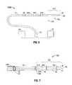
- FIG. 2is a partial, perspective view of an energy applicator according to an embodiment of the present disclosure
- FIG. 3is a partial, cross-sectional view of the energy applicator of FIG. 2 according to an embodiment of the present disclosure
- FIG. 4is an enlarged view of the indicated area of detail of FIG. 3 according to an embodiment of the present disclosure
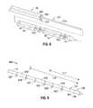
- FIG. 5is a partial, cross-sectional view of another embodiment of an energy applicator in accordance with the present disclosure.
- FIG. 6is a schematic diagram of another embodiment of an ablation system in accordance with the present disclosure.
- FIG. 7is a perspective view of a portion of an energy applicator according to another embodiment of the present disclosure.
- FIG. 8is a perspective view with parts disassembled of the portion of the energy applicator shown in FIG. 7 according to an embodiment of the present disclosure
- FIG. 9is a partial, perspective view of an energy applicator according to an embodiment of the present disclosure.
- FIG. 10is a schematic diagram of yet another embodiment of an ablation system in accordance with the present disclosure.
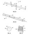
- FIG. 11is a perspective view with parts disassembled of a portion of an energy applicator according to an embodiment of the present disclosure
- FIG. 12is a perspective assembled view of the portion of the energy applicator shown in FIG. 11 according to an embodiment of the present disclosure
- FIG. 13is a perspective, partly separated view of the portion of the energy applicator of FIG. 12 provided with an elongated shaft having an opening therethrough and an end cap according to an embodiment of the present disclosure
- FIG. 14is an enlarged view of the indicated area of detail of FIG. 13 according to an embodiment of the present disclosure.
- FIG. 15is a partial, cross-sectional view of the energy applicator of FIG. 13 according to an embodiment of the present disclosure
- FIG. 16is a perspective, assembled view of the portion of the energy applicator of FIG. 13 according to an embodiment of the present disclosure
- FIG. 17is a partial, perspective view of the energy applicator of FIG. 16 shown with a dielectric sleeve member surrounding a portion of the elongated shaft including the opening in the elongated shaft, according to an embodiment of the present disclosure;
- FIG. 18is a partial, perspective view of the energy applicator of FIG. 17 shown with portions of the dielectric sleeve member and the opening in the elongated shaft (in phantom lines) surrounded by axially aligned proximal and distal electrically-conductive sleeve members having a gap therebetween according to an embodiment of the present disclosure;
- FIG. 19Ais a cross-sectional view of a distal portion of the energy applicator of FIG. 18 according to an embodiment of the present disclosure
- FIG. 19Bis a cross-sectional view of another distal portion of the energy applicator of FIG. 18 according to an embodiment of the present disclosure.
- FIG. 20is a partial, perspective view of the energy applicator of FIG. 18 shown with a tapered portion extending distally of the distal electrically-conductive sleeve member according to an embodiment of the present disclosure
- FIG. 21is a partial, perspective view of the energy applicator of FIG. 20 shown with a radiating section air-exposure balun according to an embodiment of the present disclosure
- FIG. 22is a partial, perspective view of the energy applicator of FIG. 21 shown with a layer disposed along the length of the elongated shaft and overlying the proximal and distal electrically-conductive sleeve members and the radiating section air-exposure balun and bridging the gaps therebetween according to an embodiment of the present disclosure;
- FIG. 23is a diagrammatic representation of a radiation pattern of electromagnetic energy delivered into tissue by an energy applicator, such as the energy applicator of FIG. 11 , according to an embodiment of the present disclosure
- FIG. 24is a partial, perspective view of an energy applicator according to another embodiment of the present disclosure.
- FIG. 25is a partial, perspective view of the energy applicator of FIG. 24 shown with a radiating section air-exposure balun according to an embodiment of the present disclosure
- FIG. 26is a partial, cross-sectional view of the energy applicator of FIG. 25 according to an embodiment of the present disclosure.
- FIG. 27is a flowchart illustrating a method of directing energy to tissue according to an embodiment of the present disclosure.
- proximalrefers to that portion of the apparatus that is closer to the user and the term “distal” refers to that portion of the apparatus that is farther from the user.
- a phrase in the form “A/B”means A or B.
- a phrase in the form “A and/or B”means “(A), (B), or (A and B)”.
- a phrase in the form “at least one of A, B, or C”means “(A), (B), (C), (A and B), (A and C), (B and C), or (A, B and C)”.
- Electromagnetic energyis generally classified by increasing energy or decreasing wavelength into radio waves, microwaves, infrared, visible light, ultraviolet, X-rays and gamma-rays.
- microwavegenerally refers to electromagnetic waves in the frequency range of 300 megahertz (MHz) (3 ⁇ 10 8 cycles/second) to 300 gigahertz (GHz) (3 ⁇ 10 11 cycles/second).
- ablation proceduregenerally refers to any ablation procedure, such as microwave ablation, radio frequency (RF) ablation or microwave ablation assisted resection.
- transmission linegenerally refers to any transmission medium that can be used for the propagation of signals from one point to another.
- lengthmay refer to electrical length or physical length.
- electrical lengthis an expression of the length of a transmission medium in terms of the wavelength of a signal propagating within the medium. Electrical length is normally expressed in terms of wavelength, radians or degrees. For example, electrical length may be expressed as a multiple or sub-multiple of the wavelength of an electromagnetic wave or electrical signal propagating within a transmission medium. The wavelength may be expressed in radians or in artificial units of angular measure, such as degrees.
- the electric length of a transmission mediummay be expressed as its physical length multiplied by the ratio of (a) the propagation time of an electrical or electromagnetic signal through the medium to (b) the propagation time of an electromagnetic wave in free space over a distance equal to the physical length of the medium.
- the electrical lengthis in general different from the physical length. By the addition of an appropriate reactive element (capacitive or inductive), the electrical length may be made significantly shorter or longer than the physical length.
- Embodiments of the present disclosureprovide energy applicators for treating tissue and methods of directing electromagnetic radiation to tissue.
- Embodimentsmay be implemented using electromagnetic radiation at microwave frequencies or at other frequencies.
- An electrosurgical system including an energy applicator with radiating section air-exposure balun, according to various embodiments,is designed and configured to operate between about 300 MHz and about 10 GHz.
- Various embodiments of the presently disclosed energy applicators with radiating section air-exposure balun structureare suitable for microwave ablation and for use to pre-coagulate tissue for microwave ablation assisted surgical resection.
- various methods described hereinbeloware targeted toward microwave ablation and the complete destruction of target tissue, it is to be understood that methods for directing electromagnetic radiation may be used with other therapies in which the target tissue is partially destroyed or damaged, such as, for example, to prevent the conduction of electrical impulses within heart tissue.
- the teachings of the present disclosuremay also apply to a monopole, helical, or other suitable type of microwave antenna.
- Various embodiments of the presently disclosed energy applicators with radiating section air-exposure balun structuremay include sequential and/or overlapping balun structures.
- Sequential balunsmay have a relatively short length, and may include high-dielectric materials within the non-conductive layers thereof.
- the sequential and overlapping balun structuresmay be designed to be lossless structures.
- FIG. 1shows an electrosurgical system 10 according to an embodiment of the present disclosure that includes an energy applicator (also referred to herein as an electromagnetic energy delivery device) or probe 100 .
- an energy applicatoralso referred to herein as an electromagnetic energy delivery device
- Probe 100generally includes an antenna assembly 12 having a radiating portion (e.g., 50 shown in FIG. 2 ) connected by a feedline 110 (or shaft) via a transmission line 15 to a connector 16 , which may further operably connect the probe 100 to a power generating source 28 , e.g., a microwave or RF electrosurgical generator.
- Probe 100includes a first balun structure 108 , having a proximal end 106 and a distal end 107 .
- the shape and size of the antenna assembly 12 and the first balun structure 108may be varied from the configuration depicted in FIGS. 1 and 2 .
- microwave energy having a wavelength, lambda (A)is transmitted through the antenna assembly 12 , e.g., along the radiating portion 50 , and radiated into the surrounding medium, e.g., tissue.
- First balun structure 108which is described in more detail later in this disclosure, generally includes a balun insulator (e.g., 348 shown in FIG. 3 ) and a balun outer conductor (e.g., 368 shown in FIG. 3 ) disposed around the outer peripheral surface of the balun insulator, or portions thereof, and may include a balun short (e.g., 378 shown in FIG. 3 ).
- First balun structure 108is configured to substantially confine electromagnetic radiation or energy to the radiating section 50 when the probe 100 is energized disposed in tissue. FIG.
- the first balun structure 108may be a quarter-wavelength, 1 ⁇ 4 ⁇ , sleeve balun, or a 3 ⁇ 4 ⁇ sleeve balun. Odd harmonics (e.g., 1 ⁇ 4 ⁇ , 3 ⁇ 4 ⁇ , etc.) may cause a current null at the balun entrance, which may maintain a desired radiation pattern.
- Feedline 110may be formed from a suitable flexible, semi-rigid or rigid microwave conductive cable, and may connect directly to an electrosurgical power generating source 28 . Alternatively, the feedline 110 may electrically connect the antenna assembly 12 via the transmission line 15 to the generator 28 . Feedline 110 may have a variable length from a proximal end of the antenna assembly 12 to a distal end of transmission line 15 ranging from a length of about one inch to about twelve inches. Feedline 110 may be formed of suitable electrically-conductive materials, e.g., copper, gold, silver or other conductive metals or metal alloys having similar conductivity values. Feedline 110 may be made of stainless steel, which generally offers the strength required to puncture tissue and/or skin.
- Conductive materials used to form the feedline 110may be plated with other materials, e.g., other conductive materials, such as gold or silver, to improve their properties, e.g., to improve conductivity, or decrease energy loss, etc.
- the feedline 110includes stainless steel, and to improve the conductivity thereof, the stainless steel may be coated with a layer of a conductive material such as copper or gold.
- Feedline 110may include an inner conductor, a dielectric material coaxially surrounding the inner conductor, and an outer conductor coaxially surrounding the dielectric material.
- Antenna assembly 12may be formed from a portion of the inner conductor that extends distal of the feedline 110 into the antenna assembly 12 .
- Feedline 110may be cooled by fluid, e.g., saline or water, to improve power handling, and may include a stainless steel catheter.
- the power generating source 28is configured to provide microwave energy at an operational frequency from about 300 MHz to about 2500 MHz. In other embodiments, the power generating source 28 is configured to provide microwave energy at an operational frequency from about 300 MHz to about 10 GHz. Power generating source 28 may be configured to provide various frequencies of electromagnetic energy. Transmission line 15 may additionally, or alternatively, provide a conduit (not shown) configured to provide coolant fluid from a coolant source 18 to the probe 100 .
- Antenna assembly 12generally includes an inner conductor 210 , an outer conductor 260 , and may include a first dielectric material 240 separating the inner conductor 210 and the outer conductor 260 , for example, as shown in FIGS. 3 and 4 .
- the inner conductor 210is formed from a first electrically conductive material (e.g., stainless steel) and the outer conductor 260 is formed from a second electrically conductive material (e.g., copper).
- the outer conductor 260coaxially surrounds the inner conductor 210 along a distal portion of the antenna assembly 12 .
- Inner conductor 210 and the outer conductor 260may be formed from any suitable electrically conductive material.
- First dielectric material 240may be formed from any suitable dielectric material, including, but not limited to, ceramics, water, mica, polyethylene, polyethylene terephthalate, polyimide, polytetrafluoroethylene (PTFE) (e.g., TEFLON®, manufactured by E. I. du Pont de Nemours and Company of Wilmington, Del., United States), glass, or metal oxides.
- Antenna assembly 12may be provided with a second dielectric material 29 surrounding the outer conductor 260 and/or the puck 130 , or portions thereof.
- Second dielectric material 29may be formed from any suitable dielectric material.
- the second dielectric material 29is formed from a material with a dielectric constant different than the dielectric constant of the first dielectric material 240 .
- the antenna assembly 12includes a conductor end portion 280 that may be formed from any suitable electrically conductive material.
- the conductor end portion 280is coupled to the inner conductor 210 and may be formed of the same material as the inner conductor 210 . Tapered region 120 , or portions thereof, may surround a proximal portion of the conductor end portion 280 .
- the conductor end portion 280is substantially cylindrically shaped, and may be formed from stainless steel. The shape and size of the conductor end portion 280 may be varied from the configuration depicted in FIG. 3 . In some embodiments, at least a portion of the conductor end portion 280 is surrounded by the second dielectric material 29 .
- an end cap or tapered portion 120Located at the distal end of the antenna assembly 12 is an end cap or tapered portion 120 , which may terminate in a sharp tip 123 to allow for insertion into tissue with minimal resistance.
- a straight probe with a sharp tipthat may be suitable for use as the energy applicator 100 is commercially available under the trademark EVIDENTTM offered by Covidien.
- the end cap or tapered portion 120may include other shapes, such as, for example, a tip 123 that is rounded, flat, square, hexagonal, or cylindroconical.
- Tip 123may be coated with a non-stick material, such as polytetrafluoroethylene (a.k.a. PTFE or TEFLON®, manufactured by the E. I. du Pont de Nemours and Company of Wilmington, Del., United States), polyethylene tephthalate (PET), or the like.
- the antenna assembly 12includes a distal radiating portion 105 and a proximal radiating portion 140 .
- a junction member 130(also referred to herein as a puck) couples the proximal radiating portion 140 and the distal radiating portion 105 .
- the distal and proximal radiating portions 105 , 140align at the junction member 130 , which is generally made of a dielectric material, e.g., adhesives, and are also supported by the inner conductor that extends at least partially through the distal radiating portion 105 .
- Junction member 130or portions thereof, may be disposed between the proximal and distal radiating portions, 140 and 105 .
- junction member 130may be formed from any suitable elastomeric or ceramic dielectric material by any suitable process.
- the junction member 130is formed by overmolding and includes a thermoplastic elastomer, such as, for example, polyether block amide (e.g., PEBAX®, manufactured by The Arkema Group of Colombes, France), polyetherimide (e.g., ULTEM® and/or EXTEM®, manufactured by SABIC Innovative Plastics of Saudi Arabia) and/or polyimide-based polymer (e.g., VESPEL®, manufactured by E. I. du Pont de Nemours and Company of Wilmington, Del., United States).
- Junction member 130may be formed using any suitable overmolding compound by any suitable process, and may include use of a ceramic substrate.
- the antenna assembly 12may be provided with a coolant chamber (not shown).
- the junction member 130may include coolant inflow and outflow ports (not shown) to facilitate the flow of coolant into, and out of, the coolant chamber. Examples of coolant chamber and coolant inflow and outflow port embodiments are disclosed in commonly assigned U.S. patent application Ser. No. 12/401,268 filed on Mar. 10, 2009, entitled “COOLED DIELECTRICALLY BUFFERED MICROWAVE DIPOLE ANTENNA”, and U.S. Pat. No. 7,311,703, entitled “DEVICES AND METHODS FOR COOLING MICROWAVE ANTENNAS”.
- the antenna assembly 12may be provided with an outer jacket (not shown) disposed about the distal radiating portion 105 , the junction member 130 and/or the proximal radiating portion 140 .
- the outer jacketmay be formed of any suitable material, such as, for example, polymeric or ceramic materials.
- the outer jacketmay be applied by any suitable method, such as, for example, heat shrinking, overmolding, coating, spraying dipping, powder coating, baking and/or film deposition.
- the outer jacketmay be a water cooled catheter formed of a material having low electrical conductivity.
- the probe 100is inserted into or placed adjacent to tissue and microwave energy is supplied thereto.
- Ultrasound or computed tomography (CT) guidancemay be used to accurately guide the probe 100 into the area of tissue to be treated.
- Probe 100may be placed percutaneously or atop tissue, e.g., using conventional surgical techniques by surgical staff.
- a clinicianmay pre-determine the length of time that microwave energy is to be applied.
- Application durationmay depend on many factors such as tumor size and location and whether the tumor was a secondary or primary cancer.
- the duration of microwave energy application using the probe 100may depend on the progress of the heat distribution within the tissue area that is to be destroyed and/or the surrounding tissue.
- Single or multiple probes 100may provide ablations in short procedure times, e.g., a few seconds to minutes, to destroy cancerous cells in the target tissue region.
- a plurality of probes 100may be placed in variously arranged configurations to substantially simultaneously ablate a target tissue region, making faster procedures possible. Multiple probes 100 can be used to synergistically create a large ablation or to ablate separate sites simultaneously. Tissue ablation size and geometry is influenced by a variety of factors, such as the energy applicator design, number of energy applicators used simultaneously, time and wattage.
- the length of the antenna for efficient radiationmay be dependent on the effective wavelength, ⁇ eff , which is dependent upon the dielectric properties of the medium being radiated into.
- Antenna assembly 12 through which microwave energy is transmitted at a wavelength, ⁇may have differing effective wavelengths, ⁇ eff , depending upon the surrounding medium, e.g., liver tissue, as opposed to breast tissue.
- the first balun structure 108includes a balun insulator 348 in the form of a substantially cylindrically-shaped, dielectric sleeve coaxially disposed around a distal portion of the feedline 110 , and a balun outer conductor 368 in the form of a substantially cylindrically-shaped, electrically-conductive sleeve disposed around the outer peripheral surface of the balun insulator 348 .
- Balun insulator 348may be formed of any non-conductive insulator, e.g., a TEFLON® sleeve.
- Balun insulator 348may be applied by any suitable manner, including, but not limited to, by applying a polymeric coating, and/or by positioning a heat-shrinkable tube (e.g., polyolefin) and raising the temperature thereof to conform the heat shrink tubing to the coaxial feedline 110 .
- Balun outer conductor 368may be formed of any suitable electrically-conductive material, e.g., metal such as stainless steel, titanium, etc., by any suitable process.
- First balun structure 108includes a balun short 378 disposed at the proximal end 106 a of the balun insulator 348 .
- Balun short 378may be formed of any suitable electrically-conductive materials, e.g., copper, gold, silver or other conductive metals or metal alloys. In some embodiments, the balun short 378 has a generally ring-like or truncated tubular shape.
- Balun short 378is electrically coupled to the outer conductor 260 of the feedline 110 by any suitable manner of electrical connection, e.g., soldering, welding, or laser welding.
- Balun short 378is electrically coupled to the balun outer conductor 368 by any suitable manner of electrical connection.
- the balun outer conductor 368has a substantially tubular shape, having the proximal end 106 a thereof abutting the distal end of the balun short 378 , and extending distally from the balun short 378 .
- the distal end 107 b of the balun outer conductor 368is positioned substantially adjacent to the distal end 107 a of the balun insulator 348 .
- Balun insulator 348may extend distally beyond the distal end 107 b of the balun outer conductor 368 , e.g., to enhance microwave performance of the probe 100 and/or provide a desired ablation pattern.
- Probe 100includes a second balun structure 129 (also referred to herein as an antenna radiating section air-exposure balun).
- Second balun structure 129has a proximal end 127 and a distal end 128 .
- the presently disclosed second balun structure 129is configured to substantially prevent the propagation of electromagnetic radiation or energy emitted from the antenna assembly 12 proximally, e.g., along the feedline 110 , when the probe 100 is energized but not inserted in tissue.
- FIG. 2illustrates a diagrammatic representation of a radiation pattern “R O ” of electromagnetic energy emitted by the radiating section 50 when the probe 100 is energized but not inserted in tissue, showing that the emitted energy does not propagate along the feedline 110 proximal to the distal end 128 of the second balun structure 129 .
- Second balun structure 129may include a balun outer conductor 369 coaxially disposed about the feedline 110 and insulated therefrom along the length of the balun outer conductor 369 by a balun insulator 349 , and may include a balun short 379 .
- Antenna radiating section air-exposure balun 129may be formed similar to, or different than, the first balun structure 108 .
- the shape and size of the first balun structure 108 and the second balun structure 129may be varied from the configuration depicted in FIG. 3 .
- the first balun structure 108has a distal end 107 that may be positioned at a distance “L 1 ” from the distal end of the antenna assembly 12
- the second balun structure 129has a distal end 128 that may be positioned at a distance “L 2 ” from the distal end of the antenna assembly 12 .
- the distance “L 1 ”is about one-half of a wavelength, 1 ⁇ 2 ⁇ , in tissue
- the distance “L 2 ”may be about one-half of a wavelength, 1 ⁇ 2 ⁇ , in air.
- FIG. 5shows an electromagnetic energy delivery device or probe 101 according to an embodiment of the present disclosure that includes a conductor end portion 280 , a feedline 510 , a first balun structure “B 1 ” and a second balun structure “B 2 ” (also referred to herein as an antenna radiating section air-exposure balun) disposed proximal to the first balun “B 1 ”.
- Feedline 510is similar to feedline 110 of FIG. 1 and further description thereof is omitted in the interests of brevity.
- Conductor end portion 280may be formed from any suitable electrically conductive material.
- the conductor end portion 280is coupled to an inner conductor 210 and may be formed of the same material as the inner conductor 210 .
- first balun structure “B 1 ” and the second balun structure “B 2 ”, which are described below,may be varied from the configuration depicted in FIG. 5 .
- the distal end of the outer conductor 260may be spaced apart by a gap “G” from the proximal end of the conductor end portion 280 to define a feed point therebetween.
- First balun structure “B 1 ”generally includes a first balun portion 519 , a second balun portion 529 and a third balun portion 539 .
- the second balun portion 529may be disposed so as to at least partially overlap the first balun portion 519
- the third balun portion 539may be disposed so as to at least partially overlap the second balun portion 529 .
- First balun portion 519includes a balun insulator 548 in the form of a substantially cylindrically-shaped.
- Dielectric sleevecoaxially disposed around a distal portion 507 of the outer conductor 260 , and a balun outer conductor 568 in the form of a substantially cylindrically-shaped.
- Electrically-conductive sleevedisposed around the outer peripheral surface of the balun insulator 548 , or portion thereof.
- Balun outer conductor 568is electrically coupled to the outer conductor 260 at the proximal end 578 of the balun outer conductor 568 , e.g., by solder or other suitable electrical connection.
- Balun insulator 548may be formed of any suitable insulative material, including, but not limited to, ceramics, water, mica, polyethylene, polyethylene terephthalate, polyimide, polytetrafluoroethylene (PTFE) (e.g., Teflon®, manufactured by E. I. du Pont de Nemours and Company of Wilmington, Del., United States), glass, metal oxides or other suitable insulator, and may be formed in any suitable manner.
- Balun outer conductor 568may be formed of any suitable electrically-conductive materials, e.g., copper, gold, silver or other conductive metals or metal alloys.
- Second balun portion 529includes a balun insulator 549 and a balun outer conductor 569 disposed around the outer peripheral surface of the balun insulator 549 , or portion thereof.
- Balun insulator 549is disposed around a distal portion 508 of the outer conductor 260 , and may overlap at least a proximal portion of the first balun portion 519 .
- Balun outer conductor 569is electrically coupled to the outer conductor 260 using any suitable electrical connection.
- the proximal end 579 of the balun outer conductor 569may be adapted to allow for connection, e.g., electrically and mechanically, to the outer conductor 260 .
- Third balun portion 539includes a balun insulator 550 and a balun outer conductor 570 disposed around the outer peripheral surface of the balun insulator 550 , or a portion thereof.
- Balun insulator 550is disposed around a distal portion 509 of the outer conductor 260 , and may overlap at least a proximal portion of the second balun portion 529 .
- Balun outer conductor 570is electrically coupled to the outer conductor 260 using any suitable electrical connection.
- the proximal end 580 of the balun outer conductor 570may be adapted to allow for connection, e.g., electrically and mechanically, to the outer conductor 260 .
- the shape, size, spacing, and relative positions of the first balun portion 519 , the second balun portion 529 , and the third balun portion 539may be varied from the configuration depicted in FIG. 5 .
- Antenna radiating section air-exposure balun “B 2 ”may be formed as a nested or overlapping balun (e.g., similar to the first balun structure “B 1 ” shown in FIG. 5 ).
- antenna radiating section air-exposure balun “B 2 ”is a sleeve balun including a balun insulator 547 and a balun outer conductor 567 disposed around the outer peripheral surface of the balun insulator 547 , or portion thereof.
- Balun outer conductor 567may be formed of any suitable electrically-conductive materials, e.g., copper, gold, silver or other conductive metals or metal alloys.
- Balun insulator 547may be formed of any non-conductive insulator, e.g., a TEFLON® sleeve.
- Balun outer conductor 567is electrically coupled to the outer conductor 260 at the proximal end 577 of the balun outer conductor 567 by soldering or other means.
- FIG. 6shows an electrosurgical system 1000 , according to an embodiment of the present disclosure that includes an energy applicator or probe 102 .
- Probe 102generally includes an antenna assembly 212 having a radiating portion 730 connected by a feedline 26 (or shaft) via a transmission line 15 to a connector 16 , which may further operably connect the probe 102 to a power generating source 28 , e.g., a microwave or RF electrosurgical generator.
- Transmission line 15may provide a conduit (not shown) configured to provide coolant fluid from a coolant source 18 to the probe 102 .
- Feedline 26generally includes an inner conductor 210 , an outer conductor 260 , and a dielectric material 240 separating the inner conductor 210 and the outer conductor 260 .
- Feedline 26is similar to the feedline 110 of FIG. 1 and further description thereof is omitted in the interests of brevity.
- the probe 102includes a tapered end 36 that terminates in a tip 38 at the distal end of the radiating portion 730 .
- Tapered end 36allows for insertion of the probe 102 into tissue with minimal resistance.
- the tip 38may be rounded or flat.
- the probe 102includes a first balun structure 608 disposed around the feedline 26 , a second balun structure 629 disposed around the feedline 26 proximal to the first balun structure 629 , and a third balun structure 639 disposed around the feedline 26 proximal to the second balun structure 629 .
- the first balun structure 608has a distal end 607 and a proximal end 606 .
- the first balun structure 608substantially confines microwave energy from the generator 28 to the radiating portion 730 of the probe 102 .
- the first balun structure 608may include an inner dielectric layer 32 and an outer conductive layer 34 .
- First balun structure 608may be implemented with a quarter-wave short by using the outer conductive layer 34 around the outer conductor 260 of the feedline 26 separated by the dielectric layer 32 .
- First balun structure 608is shorted to the outer conductor 260 of the feedline 26 at the proximal end of the first balun structure 608 by soldering or other means.
- the length of the first balun structure 608may be from a quarter to a full wavelength.
- the dielectric layer 32is formed from a fluoropolymer such as tetrafluorethylene, perfluorpropylene, or the like, and may have a thickness of about 0.005 inches.
- the outer conductive layer 34may be formed from a highly conductive metal, e.g., copper.
- the shape and size of the first balun structure 608may be varied from the configuration depicted in FIG. 6 .
- Inner conductor 210 of the feedline 26extends distal to the distal end 607 of the first balun structure 608 , with the dielectric material 240 and the outer conductor 260 terminating at the proximal end (e.g., 241 shown in FIGS. 8 and 9 ) of the radiating portion 730 .
- Inner conductor 210is extruded from the feedline 26 and extends into the radiating portion 730 where the inner conductor 210 is centrally disposed.
- the extruded portion 211 of the inner conductor 210may include one or more conductive disks, e.g., a first conductive disk 40 a and a second conductive disk 40 b , coaxially disposed thereon.
- First and second conductive disks, 40 a and 40 bmay be disposed substantially perpendicular to a longitudinal axis defined by the inner conductor 210 .
- the first and second conductive disks, 40 a and 40 bhave a thickness from about 0.01 inches to about 0.02 inches, and may have a diameter from about 0.04 inches to about the thickness of the feedline 26 , which in one embodiment is about 0.085 inches.
- First and second conductive disks, 40 a and 40 bmay be of different sizes, diameters and thickness.
- Conductive disks 40are spaced on the inner conductor 210 such that the desired bandwidth is obtained.
- Conductive disks 40divide the radiating portion 730 into a number of spaces 42 . Examples of radiating portions divided into spaces by conductive disk embodiments are disclosed in commonly assigned U.S. patent application Ser. No.
- the spaces 42are filled with a dielectric material 44 , e.g., to improve the impedance match between the probe 102 and the power generating source 28 .
- the dielectric material 44has a dielectric constant of about 2.5 to about 30, and may be made from a ceramic material, such as alumina ceramic, or a plastic material, such as a polyamide plastic (e.g., Vespel®, available from E. I. du Pont de Nemours and Company of Wilmington, Del., United States).
- Dielectric material 44may be configured with a central channel 45 extending longitudinally therethrough to accommodate the inner conductor 210 .
- the second balun structure 629has a distal end 628 and a proximal end 627
- the third balun structure 639has a distal end 638 and a proximal end 637
- the distal end 628 of the second balun structure 629is positioned at a distance “L 1 ” from the second conductive disk 40 b
- the third balun structure 639is positioned at a distance “L 2 ” from the second conductive disk 40 b , as shown in FIG. 9 .
- the distances “L 1 ” and “L 2 ”may be any suitable length and may be measured in fractions of a wavelength. In some embodiments, the distance “L 1 ” is about one-half of a wavelength measured in air and the distance “L 2 ” is about one wavelength measured in air.
- the distal end 628 of the second balun structure 629 and/or the distal end 638 of the third balun structure 639may be positioned at a distance that is a fraction of a wavelength (e.g., measured in air) from the first conductive disk 40 a . In some embodiments, the distal end 628 of the second balun structure 629 and/or the distal end 638 of the third balun structure 639 may be positioned at a distance that is a fraction of a wavelength (e.g., measured in air) from the proximal end 241 of the radiating portion 730 .
- Embodiments of the second balun structure 629 and/or the third balun structure 639may be manually or automatically movable structures that selectably allow positioning thereof at a range of positions along the feedline 26 .
- Probe 102may be configured to provide automatically adjustable positioning of the second balun structure 629 and/or the third balun structure 639 at various positions relative to a suitable reference position on the probe 102 . Examples of reference positions that may be suitable include the location of the first conductive disk 40 a , the location of the second conductive disk 40 b , the distal end of the radiating portion 730 , and the proximal end 241 of the radiating portion 730 .
- FIG. 10shows an electrosurgical system 1100 according to an embodiment of the present disclosure that includes an energy applicator or probe 103 with a directional radiation pattern (e.g., “R” shown in FIG. 23 ).
- Probe 103generally includes an antenna assembly 312 having a radiating portion 30 connected by a feedline 110 (or shaft) via a transmission line 15 to a connector 16 , which may further operably connect the probe 103 to a power generating source 28 , e.g., a microwave or RF electrosurgical generator.
- Located at the distal end of the antenna assembly 312is an end cap or tapered portion 120 , which may terminate in a sharp tip 123 to allow for insertion into tissue with minimal resistance.
- An embodiment of an energy applicator with a directional radiation pattern suitable for use in tissue ablation applications, such as the probe 103 of FIG. 10 , in accordance with the present disclosure,is shown in more detail in FIGS. 11 through 22 .
- FIGS. 11 through 22show a sequentially-illustrated, assembly of components forming an energy applicator or probe 103 having a dielectric loaded coaxial aperture (e.g., “W” shown in FIG. 22 ) with distally positioned resonant structure (e.g., 909 shown in FIG. 18 ) in accordance with the present disclosure.
- a dielectric loaded coaxial aperturee.g., “W” shown in FIG. 22
- distally positioned resonant structuree.g., 909 shown in FIG. 18
- embodiments of an energy applicator with a directional radiation pattern in accordance with the present disclosuremay include a radiating section air-exposure balun 839 .
- an energy applicator segment or probe(shown generally as 20 in FIGS. 11 and 12 ) is provided with a coaxial feedline 226 having an inner conductor 220 that extends along the longitudinal axis “A” of the energy applicator segment 200 , an outer conductor 224 coaxially disposed about the inner conductor 220 , and a dielectric material 222 disposed therebetween.
- the inner conductor 220has a diameter “D 1 ” and the dielectric material 222 has an outer diameter “D 2 ”.
- a portion of the dielectric material 222may extend beyond the outer conductor 224 . Additionally, or alternatively, a portion of the inner conductor 220 (e.g., 22 shown in FIG. 11 ) may extend beyond the dielectric material 222 and the outer conductor 224 .
- the antenna assembly 312may be coupled to the inner conductor portion 22 .
- the antenna assembly 312may be coupled to an elongated conductor (e.g., similar to the inner conductor portion 22 ), wherein the elongated conductor is electrically coupled to the inner conductor 220 of the feedline 226 .
- a proximal cylindrical dielectric sleeve 244may be coupled to the inner conductor 220 at a distal end of the coaxial feedline 226 . Additionally, or alternatively, a first dielectric segment 284 and a second dielectric segment 274 may be coupled to the inner conductor 220 . Additionally, or alternatively, a distal cylindrical dielectric sleeve 264 may be coupled to the inner conductor 220 .
- Proximal cylindrical dielectric sleeve 244 , first dielectric segment 284 and a second dielectric segment 274may be formed from dielectric materials that provide an impedance match from the coaxial feedline 226 .
- First dielectric segment 284may be formed from a material with a dielectric constant that is higher than the dielectric constant of the second dielectric segment 274 , e.g., to maximize energy radiated into the surrounding medium, e.g., tissue.
- a proximal cylindrical dielectric sleeve 244having a diameter “D 2 ”, is coupled to the inner conductor 220 .
- Proximal cylindrical dielectric sleeve 244may be configured with a central channel 245 extending longitudinally therethrough to accommodate the inner conductor 220 .
- Proximal cylindrical dielectric sleeve 244may be formed from any suitable dielectric material.
- the proximal cylindrical dielectric sleeve 244is formed from a material with a dielectric constant in the range of about 2 to about 10.
- a distal cylindrical dielectric sleeve 264having a diameter “D 2 ”, is coupled to the inner conductor 220 .
- Distal cylindrical dielectric sleeve 264may be formed from any suitable dielectric material.
- Distal cylindrical dielectric sleeve 264may be disposed distally of the proximal cylindrical dielectric sleeve 244 and may be configured with a central channel 265 extending longitudinally therethrough to accommodate the inner conductor 220 .
- the distal cylindrical dielectric sleeve 264is formed from a material with a dielectric constant different than the dielectric constant of the proximal cylindrical dielectric sleeve 244 .
- Distal cylindrical dielectric sleeve 264may be a high dielectric material, e.g., a material with a dielectric constant in the range of about 3 to about 50, to shorten the effective wavelength, ⁇ eff , of energy.
- the length of the distal cylindrical dielectric sleeve 264may be varied, depending on the dielectric constant of the material selected, to allow positioning of a radiating aperture (e.g., “W” shown in FIGS. 22 and 23 ) at a quarter wavelength (or half wavelength, etc.) from a distal short (e.g., “P” shown in FIGS. 13 and 15 ).
- a radiating aperturee.g., “W” shown in FIGS. 22 and 23
- a quarter wavelengthor half wavelength, etc.
- Pshown in FIGS. 13 and 15
- ⁇c f ⁇ ⁇ r , ( 1 )
- cthe speed of light
- fthe frequency
- ⁇ rthe dielectric constant
- first dielectric segment 284 and a second dielectric segment 274are coupled to the inner conductor 220 .
- the first and second dielectric segments 284 , 274may be disposed between the proximal cylindrical dielectric sleeve 244 and the distal cylindrical dielectric sleeve 264 .
- First and second dielectric segments 284 , 274generally include one or more flat planar surfaces and a partial cylindrical surface. The shape and size of the first and second dielectric segments 284 , 274 may be varied from the configuration depicted in FIGS. 11 through 13 .
- the first dielectric segment 284is formed from a material with a dielectric constant in the range of about 2 to about 30.
- the second dielectric segment 274is formed from a material with a dielectric constant in the range of about 2 to about 30.
- the first dielectric segment 284has a substantially half-cylindrical shape, having a diameter “D 3 ”, and includes a flat planar surface configured with a recess in the form of a groove 287 extending longitudinally across the flat planar surface.
- the second dielectric segment 274has a substantially half-cylindrical shape, having a diameter “D 2 ”, and includes a flat planar surface configured with a recess in the form of a groove 277 extending longitudinally across the flat planar surface. Grooves 287 and 277 may be configured to accommodate a portion of the inner conductor 220 .
- first and second dielectric segments 284 , 274when the first and second dielectric segments 284 , 274 are coupled to the inner conductor 220 , the respective flat planar surfaces of the first and second dielectric segments 284 , 274 contact one another.
- the shape and size of the grooves 287 and 277may be varied from the configuration depicted in FIG. 11 .
- FIGS. 13 through 16show an energy applicator segment 30 according to an embodiment of the present disclosure that is similar to the energy applicator segment 20 of FIG. 11 , except for an elongated shaft 480 (outlined in bold lines in FIG. 13 ) having an opening 440 therethrough, and an end cap “P” disposed distally to the distal end of the elongated shaft 480 .
- the elongated shaft 480has an inner diameter “D 2 ” and an outer diameter “D 3 ”.
- the end cap “P”may have a disc- or plate-like shape. End cap “P” may be formed of any suitable electrically-conductive material, e.g., metal such as stainless steel, titanium, etc. As shown in FIG.
- the proximal surface “S” of the end cap “P”makes contact with both the distal end of the inner conductor 220 and the distal end of the elongated shaft 480 , thereby forming a distal short.
- the shape and size of the end cap “P”may be varied from the configuration depicted in FIGS. 13 and 15 .
- the opening 440 in the elongated shaft 480may be aligned with the first dielectric segment 284 .
- the first dielectric segment 284 and the elongated shaft 480may be substantially concentric to a longitudinal axis (e.g., “A′′-A” shown in FIG. 11 ) of the energy applicator.
- Elongated shaft 480may be electrically coupled to the outer conductor 224 of the coaxial feedline 226 .
- Opening 440is made by removing a radial portion the elongated shaft 480 an optimized length back from the distal short.
- the opening 440is positioned to maximize directivity and coupling of microwave energy into tissue, e.g., opening 440 may be placed at the voltage maximum of the standing wave created by the shorted coaxial distal end.
- Opening 440may be of any length and radial angle to achieve the desired amount of coax to free space coupling and radiation directivity.
- the dielectric constant of dielectric materials on either side of the opening 440 , proximal or distal,may vary with distance from the opening 440 to achieve impedance match and optimal energy delivery and directivity to tissue.
- the dielectric materials filling the coaxial structure at the site of the opening 440may vary in dielectric constant with shells or more complex dielectric layering to achieve the optimum antenna directivity and energy to tissue delivery.
- the first dielectric segment 284has a diameter “D 2 ” and the elongated shaft 480 has an outer diameter “D 3 ”, where “D 3 ” is larger than “D 2 ”.
- the opening 440may be filled with a nonconductive radio frequency transparent material, e.g., a glass fiber epoxy composite or polyimide. This may be accomplished in an over molding process.
- the windowmay also be created by placing a heat shrink or rigid composite sleeve along the entire antenna assembly. Examples of dielectric material configurations at the site of a window or opening in an energy applicator are disclosed in commonly assigned U.S.
- FIG. 17shows an energy applicator segment 40 according to an embodiment of the present disclosure that is similar to the energy applicator segment 30 of FIG. 16 , except for a dielectric sleeve member 740 (also referred to herein as a balun insulator) disposed coaxially about a portion of the elongated shaft 480 .
- Balun insulator 740may be formed of any non-conductive insulator, e.g., a TEFLON® sleeve.
- Balun insulator 740may extend fully or partially over the opening 440 in the elongated shaft. In some embodiments, the balun insulator 740 extends fully over the opening 440 and the half-cylindrical dielectric member 284 disposed therein.
- balun insulator 740may be varied from the configuration depicted in FIG. 17 .
- Balun insulator 740may extend beyond the open ends of one or more electrically-conductive sleeve members (e.g., 871 and 872 shown in FIG. 18 ) of a balun structure (e.g., 909 shown in FIG. 18 ) to enhance effectiveness of the balun.
- FIG. 18shows an energy applicator segment 50 according to an embodiment of the present disclosure that is similar to the energy applicator segment 40 of FIG. 17 , except for a first electrically-conductive sleeve member 871 and a second electrically-conductive sleeve member 872 (also referred to herein as balun outer conductors) axially aligned with a gap 940 therebetween.
- a proximal end portion of the first electrically-conductive sleeve member 871may be coupled to a proximal portion of the elongated shaft 480 .
- a distal end portion of the second electrically-conductive sleeve member 872may be coupled to a distal portion of the elongated shaft 480 , e.g., as shown in FIG. 19A .
- First and second electrically-conductive sleeve members 871 , 872may be formed of any suitable electrically-conductive material, e.g., metal such as stainless steel, aluminum, titanium, copper, etc.
- First and second electrically-conductive sleeve members 871 , 872may overlap portions of the window 440 in the elongated shaft 480 . As shown in FIG. 18 , the first electrically-conductive sleeve member 871 may overlap a proximal portion 401 , having a length “L 1 ”, of the window 440 , and the second electrically-conductive sleeve member 872 may overlap a distal portion 402 , having a length “L 2 ”, of the window 440 , whereby a gap 940 , having a length “L 3 ”, is formed therebetween.
- the first electrically-conductive sleeve member 871has a length “L 4 ”, wherein “L 4 ” may be a quarter wavelength or a half wavelength.
- the second electrically-conductive sleeve member 872has a length “L 5 ”, wherein “L 5 ” may be a quarter wavelength or a half wavelength.
- First and second electrically-conductive sleeve members 871 , 872may have any suitable length.
- FIG. 20shows an energy applicator segment 60 according to an embodiment of the present disclosure that is similar to the energy applicator segment 50 of FIG. 18 , except for a tapered portion 920 extending distally from the distal end cap “P”.
- Tapered portion 920may terminate in a sharp tip 923 to allow for insertion into tissue with minimal resistance. In those cases where the energy applicator segment 60 is inserted into a pre-existing opening, the tip 923 may be rounded or flat.
- the shape and size of the tapered portion 920may be varied from the configuration depicted in FIG. 20 .
- FIG. 21shows an energy applicator segment 70 according to an embodiment of the present disclosure that is similar to the energy applicator segment 60 of FIG. 20 , except for a radiating section air-exposure balun disposed proximal to the first and second electrically-conductive sleeve members 871 , 872 of the distally positioned resonant structure (e.g., 909 shown in FIG. 18 ).
- a radiating section air-exposure balundisposed proximal to the first and second electrically-conductive sleeve members 871 , 872 of the distally positioned resonant structure (e.g., 909 shown in FIG. 18 ).
- FIG. 22shows an embodiment of an energy applicator 103 in accordance with the present disclosure.
- an outer jacket 1020may be provided to the energy applicator segment 70 of FIG. 21 .
- the outer jacket 1020is made of an insulating material, such as, for example, a polyimide or similar dielectric material.
- Outer jacket 1020may be a water-cooled catheter formed of a material having low electrical conductivity.
- the outer surface of the outer jacket 1020may be coated with a suitable lubricious substance, such as TEFLON®, to aid in the movement of the outer jacket 1020 in or through tissue as well as to aid in preventing tissue from sticking thereto.
- FIG. 23shows an embodiment of an energy applicator (e.g., 103 shown in FIG. 22 ) coupled to a transmission line 15 according to the present disclosure.
- Transmission line 15may connect the energy applicator 800 to a power generating source, e.g., a microwave or RF electrosurgical generator.
- a power generating sourcee.g., a microwave or RF electrosurgical generator.
- the energy applicator 103is inserted into or placed adjacent to tissue “T” and energy is supplied thereto.
- Energy applicator 103may be placed percutaneously or atop tissue.
- Ultrasound or computed tomography (CT) guidancemay be used to accurately guide the energy applicator 800 into the area of tissue “T” to be treated.
- CTcomputed tomography
- Energy applicator 103may be rotatable about a longitudinal axis “A-A” (shown in FIG. 11 ) such that the directional radiation pattern “R” rotates therewith.
- Examples of antenna assemblies rotatable about axis “A-A” such that any elongated radiation lobes rotates therewithare disclosed in commonly assigned U.S. patent application Ser. No. 12/197,405 filed on Aug. 25, 2008, entitled “MICROWAVE ANTENNA ASSEMBLY HAVING A DIELECTRIC BODY PORTION WITH RADIAL PARTITIONS OF DIELECTRIC MATERIAL”.
- Energy applicator 103may include an indicia alignment mark (not shown) such as a colored strip or the like (e.g., to provide a visual cue to the surgeon to allow orientation of the direction of flow of the energy to coincide with the indicia alignment mark) and/or indicia graduation marks (not shown) for insertion depth reference (e.g., to indicate the position of the opening “W” relative to the surface of the tissue “T”).
- indicia alignment mark and the indicia graduation mark embodimentsare disclosed in commonly assigned U.S. patent application Ser. No. 12/476,960 filed on Jun. 2, 2009, entitled “ELECTROSURGICAL DEVICES WITH DIRECTIONAL RADIATION PATTERN”.
- FIGS. 24 and 25show a sequentially-illustrated, assembly of components forming an energy applicator or probe 104 according to an embodiment of the present disclosure that includes an overlapping balun structure “B”.
- FIG. 26shows a cross-sectional view of the probe 104 including the balun structure “B” according to an embodiment of the present disclosure.
- Probe 104generally includes a feedline 2426 having an inner conductor 210 , an outer conductor 260 , and a dielectric material 240 disposed therebetween, and a radiating section 2405 operably coupled to the feedline 2426 .
- the probe 104includes a tapered end 2436 that terminates in a tip 2438 at the distal end of the radiating portion 2405 . Tapered end 2436 allows for insertion of the probe 104 into tissue with minimal resistance. In cases where the radiating portion 2405 is inserted into a pre-existing opening, the tip 2438 may be rounded or flat.
- the radiating section 2405 of the probe 104includes a conductor end portion 280 that is formed from any suitable electrically conductive material.
- Conductor end portion 280is electrically coupled to the inner conductor 210 , and may have any suitable length.
- Probe 104may include a distal radiating portion 105 and a proximal radiating portion 140 .
- a junction member 130couples the proximal radiating portion 140 and the distal radiating portion 105 .
- Conductor end portion 280 and the junction member 130 shown in FIG. 26are similar to the like-numbered conductor end portion and junction member of FIG. 3 and further description thereof is omitted in the interests of brevity.
- Balun structure “B”generally includes a first balun structure 2408 disposed proximal to the radiating section 2405 , and a second balun structure 2419 (also referred to herein as an antenna radiating section air-exposure balun) overlapping a proximal portion 2410 of the first balun structure 2408 .
- the presently-disclosed balun structure “B”is configured to substantially prevent the propagation of energy emitted from the radiating section 2405 of the probe 104 proximally, e.g., along the feedline 2426 , when the probe 104 is energized but not disposed in tissue.
- First balun structure 2408includes a distal end 2407 and a proximal end 2409 , and the antenna radiating section air-exposure balun 2419 including a distal end 2418 and a proximal end 2420 .
- First balun structure 2408may have any suitable length “L 7 ”, and the antenna radiating section air-exposure balun 2419 may have any suitable length “L 8 ”.
- the antenna radiating section air-exposure balun 2419overlaps the first balun structure 2408 by a length “L 10 ”.
- First balun structure 2408may include a balun outer conductor 2468 (e.g., similar to the balun outer conductor 368 of the first balun structure 108 of FIG. 3 ) coaxially disposed about a balun insulator 2448 (e.g., similar to the balun insulator 348 of FIG. 3 ), or portions thereof.
- Balun insulator 2448may extend distally beyond the distal end of the balun outer conductor 2468 , e.g., to enhance microwave performance of the probe 104 and/or provide a desired ablation pattern.
- the balun outer conductor 2468may include a segment 2468 a that extends proximal to the proximal end 2409 of the first balun structure 2408 .
- Balun outer conductor segment 2468 aaccording to embodiments of the present disclosure forms a smooth inner conductor layer for the antenna radiating section air-exposure balun 2419 .
- First balun structure 2408includes a balun short 2478 disposed at the proximal end of the balun insulator 2448 .
- Balun short 2478may be formed of any suitable electrically-conductive materials, e.g., copper, gold, silver or other conductive metals or metal alloys. In some embodiments, the balun short 2478 has a generally ring-like or truncated tubular shape.
- Balun short 2478is electrically coupled to the outer conductor 260 of the feedline 2426 by any suitable manner of electrical connection, e.g., soldering, welding, or laser welding.
- Balun short 2478is electrically coupled to the balun outer conductor 2468 by any suitable manner of electrical connection.
- Antenna radiating section air-exposure balun 2419includes a balun insulator 2449 coaxially disposed about a proximal portion 2410 of the first balun structure 2408 .
- Balun insulator 2449may extend to the proximal end 2469 of the balun outer conductor segment 2468 a .
- Balun insulator 2449may be formed of any non-conductive insulator, e.g., a Teflon® sleeve, and may be applied by any suitable manner.
- a balun outer conductor 2469is coaxially disposed about the balun insulator 2449 , or portions thereof.
- Balun outer conductor 2469is electrically coupled to the outer conductor 260 using any suitable electrical connection.
- the proximal end 2479 of the balun outer conductor 2469may be adapted to allow for connection, e.g., electrically and mechanically, to the outer conductor 260 .
- the radiating section 2405when the probe 104 is energized in tissue, the radiating section 2405 has a length “L 6 ”, e.g., 1 ⁇ 2 ⁇ (in tissue), and when the energy applicator 104 is energized but not disposed in tissue, the radiating section has a length “L 9 ”, e.g., 1 ⁇ 2 ⁇ (in air).
- FIG. 27is a flowchart illustrating a method of directing energy to tissue according to an embodiment of the present disclosure.
- an energy applicatore.g., 100 shown in FIG. 1
- the energy applicatorincludes a feedline (e.g., 110 shown in FIG. 1 ) having an inner conductor (e.g., 210 shown in FIG. 3 ), an outer conductor (e.g., 260 shown in FIG. 3 ), and a dielectric material (e.g., 240 shown in FIG. 3 ) disposed therebetween, and an antenna assembly (e.g., 12 shown in FIG. 1 ) having a radiating section (e.g., 50 shown in FIG. 2 ) operably coupled to the feedline.
- a feedlinee.g., 110 shown in FIG. 1
- an inner conductore.g., 210 shown in FIG. 3
- an outer conductore.g., 260 shown in FIG. 3
- a dielectric materiale.g.,
- the energy applicator(e.g., 100 shown in FIG. 1 ) also includes a first balun (e.g., 108 shown in FIG. 1 ) configured to substantially confine energy to the radiating section, and a second balun (e.g., 129 shown in FIG. 1 ) configured to substantially prevent energy emitted from the radiating section from propagating proximal to the second balun along the feedline when the energy applicator is energized but not inserted in tissue.
- the first balun structuremay be a quarter-wave sleeve balun.
- the energy applicator(e.g., 100 shown in FIG. 1 ) is positioned to tissue.
- the energy applicatormay be inserted directly into tissue (e.g., “T” shown in FIG. 24 ), inserted through a lumen, e.g., a vein, needle, endoscope or catheter, placed into the body during surgery by a clinician, or positioned in the body by other suitable methods known in the art.
- the energy applicatormay be configured to operate with a directional radiation pattern.
- step 2730energy is transmitted from an energy source (e.g., 28 shown in FIG. 1 ) through the radiating section (e.g., 50 shown in FIG. 2 ) to tissue.
- the energy sourcemay be any suitable electrosurgical generator for generating an output signal.
- the energy sourceis a microwave energy source, and may be configured to provide microwave energy at an operational frequency from about 300 MHz to about 10 GHz.
- the above-described electrosurgical devicesincluding embodiments of a radiating section air-exposure balun in accordance with the present disclosure for treating tissue and methods of directing electromagnetic radiation to a target volume of tissue may help protect a user against health risks associated with radiation exposure, e.g., by limiting and/or reducing the user's risk of exposure to radiation when the probe is energized but not inserted in tissue.
Landscapes
- Health & Medical Sciences (AREA)
- Surgery (AREA)
- Life Sciences & Earth Sciences (AREA)
- Biomedical Technology (AREA)
- Medical Informatics (AREA)
- Nuclear Medicine, Radiotherapy & Molecular Imaging (AREA)
- Electromagnetism (AREA)
- Engineering & Computer Science (AREA)
- Physics & Mathematics (AREA)
- Heart & Thoracic Surgery (AREA)
- Otolaryngology (AREA)
- Molecular Biology (AREA)
- Animal Behavior & Ethology (AREA)
- General Health & Medical Sciences (AREA)
- Public Health (AREA)
- Veterinary Medicine (AREA)
- Surgical Instruments (AREA)
- Waveguides (AREA)
- Details Of Aerials (AREA)
Abstract
Description
where c is the speed of light, f is the frequency, and ∈ris the dielectric constant. For example, in a case where an aperture is to be positioned at a quarter wavelength, given a dielectric sleeve having a dielectric constant ∈r, using
Claims (17)
Priority Applications (7)
| Application Number | Priority Date | Filing Date | Title |
|---|---|---|---|
| US12/777,984US9561076B2 (en) | 2010-05-11 | 2010-05-11 | Electrosurgical devices with balun structure for air exposure of antenna radiating section and method of directing energy to tissue using same |
| JP2011100326AJP5776929B2 (en) | 2010-05-11 | 2011-04-28 | Electrosurgical device having a balun structure for atmospheric exposure of antenna radiating portion and method of using it to direct energy to tissue |
| EP11003822.1AEP2386261B1 (en) | 2010-05-11 | 2011-05-10 | Electrosurgical devices with balun structure for air exposure of antenna radiating section |
| US14/690,912US9603662B2 (en) | 2010-05-11 | 2015-04-20 | Electrosurgical devices with balun structure for air exposure of antenna radiating section and method of directing energy to tissue using same |
| JP2015126524AJP6093807B2 (en) | 2010-05-11 | 2015-06-24 | Electrosurgical device having a balun structure for atmospheric exposure of antenna radiating portion and method of using it to direct energy to tissue |
| US15/451,694US9888963B2 (en) | 2010-05-11 | 2017-03-07 | Electrosurgical devices with balun structure for air exposure of antenna radiating section and method of directing energy to tissue using same |
| US15/893,913US10966784B2 (en) | 2010-05-11 | 2018-02-12 | Electrosurgical devices with balun structure |
Applications Claiming Priority (1)
| Application Number | Priority Date | Filing Date | Title |
|---|---|---|---|
| US12/777,984US9561076B2 (en) | 2010-05-11 | 2010-05-11 | Electrosurgical devices with balun structure for air exposure of antenna radiating section and method of directing energy to tissue using same |
Related Child Applications (1)
| Application Number | Title | Priority Date | Filing Date |
|---|---|---|---|
| US14/690,912ContinuationUS9603662B2 (en) | 2010-05-11 | 2015-04-20 | Electrosurgical devices with balun structure for air exposure of antenna radiating section and method of directing energy to tissue using same |
Publications (2)
| Publication Number | Publication Date |
|---|---|
| US20110282336A1 US20110282336A1 (en) | 2011-11-17 |
| US9561076B2true US9561076B2 (en) | 2017-02-07 |
Family
ID=44117122
Family Applications (4)
| Application Number | Title | Priority Date | Filing Date |
|---|---|---|---|
| US12/777,984Expired - Fee RelatedUS9561076B2 (en) | 2010-05-11 | 2010-05-11 | Electrosurgical devices with balun structure for air exposure of antenna radiating section and method of directing energy to tissue using same |
| US14/690,912Expired - Fee RelatedUS9603662B2 (en) | 2010-05-11 | 2015-04-20 | Electrosurgical devices with balun structure for air exposure of antenna radiating section and method of directing energy to tissue using same |
| US15/451,694ActiveUS9888963B2 (en) | 2010-05-11 | 2017-03-07 | Electrosurgical devices with balun structure for air exposure of antenna radiating section and method of directing energy to tissue using same |
| US15/893,913Active2031-04-30US10966784B2 (en) | 2010-05-11 | 2018-02-12 | Electrosurgical devices with balun structure |
Family Applications After (3)
| Application Number | Title | Priority Date | Filing Date |
|---|---|---|---|
| US14/690,912Expired - Fee RelatedUS9603662B2 (en) | 2010-05-11 | 2015-04-20 | Electrosurgical devices with balun structure for air exposure of antenna radiating section and method of directing energy to tissue using same |
| US15/451,694ActiveUS9888963B2 (en) | 2010-05-11 | 2017-03-07 | Electrosurgical devices with balun structure for air exposure of antenna radiating section and method of directing energy to tissue using same |
| US15/893,913Active2031-04-30US10966784B2 (en) | 2010-05-11 | 2018-02-12 | Electrosurgical devices with balun structure |
Country Status (3)
| Country | Link |
|---|---|
| US (4) | US9561076B2 (en) |
| EP (1) | EP2386261B1 (en) |
| JP (2) | JP5776929B2 (en) |
Cited By (7)
| Publication number | Priority date | Publication date | Assignee | Title |
|---|---|---|---|---|
| US9888963B2 (en) | 2010-05-11 | 2018-02-13 | Covidien Lp | Electrosurgical devices with balun structure for air exposure of antenna radiating section and method of directing energy to tissue using same |
| US10251701B2 (en) | 2010-05-25 | 2019-04-09 | Covidien Lp | Flow rate verification monitor for fluid-cooled microwave ablation probe |
| US10588684B2 (en) | 2010-07-19 | 2020-03-17 | Covidien Lp | Hydraulic conductivity monitoring to initiate tissue division |
| US10993764B1 (en) | 2020-01-14 | 2021-05-04 | Microline Surgical, Inc. | Insulating grips for minimally invasive surgical instruments |
| US11058488B2 (en) | 2011-01-05 | 2021-07-13 | Covidien Lp | Energy-delivery devices with flexible fluid-cooled shaft, inflow / outflow junctions suitable for use with same, and systems including same |
| US11147622B2 (en) | 2011-03-09 | 2021-10-19 | Covidien Lp | Systems for thermal-feedback-controlled rate of fluid flow to fluid-cooled antenna assembly and methods of directing energy to tissue using same |
| US12095497B2 (en) | 2021-05-26 | 2024-09-17 | Skyworks Solutions, Inc. | Signal conditioning circuits for coupling to antenna |
Families Citing this family (34)
| Publication number | Priority date | Publication date | Assignee | Title |
|---|---|---|---|---|
| US7553309B2 (en) | 2004-10-08 | 2009-06-30 | Covidien Ag | Electrosurgical system employing multiple electrodes and method thereof |
| US10022202B2 (en) | 2013-03-15 | 2018-07-17 | Triagenics, Llc | Therapeutic tooth bud ablation |
| US8292881B2 (en) | 2009-05-27 | 2012-10-23 | Vivant Medical, Inc. | Narrow gauge high strength choked wet tip microwave ablation antenna |
| US8328799B2 (en) | 2009-08-05 | 2012-12-11 | Vivant Medical, Inc. | Electrosurgical devices having dielectric loaded coaxial aperture with distally positioned resonant structure |
| US8328800B2 (en) | 2009-08-05 | 2012-12-11 | Vivant Medical, Inc. | Directive window ablation antenna with dielectric loading |
| US8328801B2 (en) | 2009-08-17 | 2012-12-11 | Vivant Medical, Inc. | Surface ablation antenna with dielectric loading |
| US8469953B2 (en) | 2009-11-16 | 2013-06-25 | Covidien Lp | Twin sealing chamber hub |
| US8728067B2 (en) | 2010-03-08 | 2014-05-20 | Covidien Lp | Microwave antenna probe having a deployable ground plane |
| US8652127B2 (en) | 2010-05-26 | 2014-02-18 | Covidien Lp | System and method for chemically cooling an ablation antenna |
| US9241762B2 (en) | 2010-06-03 | 2016-01-26 | Covidien Lp | Specific absorption rate measurement and energy-delivery device characterization using image analysis |
| US8672933B2 (en) | 2010-06-30 | 2014-03-18 | Covidien Lp | Microwave antenna having a reactively-loaded loop configuration |
| US8932281B2 (en)* | 2011-01-05 | 2015-01-13 | Covidien Lp | Energy-delivery devices with flexible fluid-cooled shaft, inflow/outflow junctions suitable for use with same, and systems including same |
| US9028476B2 (en) | 2011-02-03 | 2015-05-12 | Covidien Lp | Dual antenna microwave resection and ablation device, system and method of use |
| JP5763263B2 (en)* | 2011-04-08 | 2015-08-12 | コビディエン エルピー | Flexible microwave catheter for natural or artificial lumens |
| ITMO20120041A1 (en)* | 2012-02-17 | 2013-08-18 | Hs Hospital Service Spa | MICROWAVE DEVICE FOR FABRIC EXTRACTION |
| CN104507408B (en) | 2012-06-22 | 2017-06-20 | 柯惠有限合伙公司 | For the microwave thermometric of microwave ablation system |
| US9993295B2 (en) | 2012-08-07 | 2018-06-12 | Covidien Lp | Microwave ablation catheter and method of utilizing the same |
| US9987087B2 (en)* | 2013-03-29 | 2018-06-05 | Covidien Lp | Step-down coaxial microwave ablation applicators and methods for manufacturing same |
| US10624697B2 (en) | 2014-08-26 | 2020-04-21 | Covidien Lp | Microwave ablation system |
| US10813691B2 (en)* | 2014-10-01 | 2020-10-27 | Covidien Lp | Miniaturized microwave ablation assembly |
| GB2545465A (en) | 2015-12-17 | 2017-06-21 | Creo Medical Ltd | Electrosurgical probe for delivering microwave energy |
| GB2550537B (en)* | 2016-02-11 | 2018-04-04 | Gyrus Medical Ltd | Microwave ablation antenna assemblies |
| US10813692B2 (en) | 2016-02-29 | 2020-10-27 | Covidien Lp | 90-degree interlocking geometry for introducer for facilitating deployment of microwave radiating catheter |
| US11065053B2 (en)* | 2016-08-02 | 2021-07-20 | Covidien Lp | Ablation cable assemblies and a method of manufacturing the same |
| US10376309B2 (en) | 2016-08-02 | 2019-08-13 | Covidien Lp | Ablation cable assemblies and a method of manufacturing the same |
| US11197715B2 (en) | 2016-08-02 | 2021-12-14 | Covidien Lp | Ablation cable assemblies and a method of manufacturing the same |
| CN106129631B (en)* | 2016-08-18 | 2018-12-18 | 昆山九华电子设备厂 | A kind of leaky-wave antenna with non-uniform attenuation's constant for microwave heating equipment |
| CN108066003A (en)* | 2017-12-29 | 2018-05-25 | 浙江归创医疗器械有限公司 | Ablation catheter |
| EP3745975B1 (en)* | 2018-02-02 | 2024-07-03 | Varian Medical Systems, Inc. | Microwave ablation antennas |
| CN111684650B (en)* | 2018-03-29 | 2024-12-24 | 直观外科手术操作公司 | Systems and methods related to flexible antennas |
| GB2576481B (en) | 2018-05-30 | 2022-07-20 | Creo Medical Ltd | Electrosurgical instrument |
| GB2575485A (en)* | 2018-07-12 | 2020-01-15 | Creo Medical Ltd | Electrosurgical instrument |
| GB2575484A (en)* | 2018-07-12 | 2020-01-15 | Creo Medical Ltd | Electrosurgical instrument |
| EP4413935A3 (en)* | 2019-06-06 | 2024-09-18 | TriAgenics, Inc. | Ablation probe systems |
Citations (149)
| Publication number | Priority date | Publication date | Assignee | Title |
|---|---|---|---|---|
| DE390937C (en) | 1922-10-13 | 1924-03-03 | Adolf Erb | Device for internal heating of furnace furnaces for hardening, tempering, annealing, quenching and melting |
| DE1099658B (en) | 1959-04-29 | 1961-02-16 | Siemens Reiniger Werke Ag | Automatic switch-on device for high-frequency surgical devices |
| FR1275415A (en) | 1960-09-26 | 1961-11-10 | Device for detecting disturbances for electrical installations, in particular electrosurgery | |
| DE1139927B (en) | 1961-01-03 | 1962-11-22 | Friedrich Laber | High-frequency surgical device |
| DE1149832B (en) | 1961-02-25 | 1963-06-06 | Siemens Reiniger Werke Ag | High frequency surgical apparatus |
| FR1347865A (en) | 1962-11-22 | 1964-01-04 | Improvements to diathermo-coagulation devices | |
| DE1439302A1 (en) | 1963-10-26 | 1969-01-23 | Siemens Ag | High-frequency surgical device |
| SU401367A1 (en) | 1971-10-05 | 1973-10-12 | Тернопольский государственный медицинский институт | BIAKTIVNYE ELECTRO SURGICAL INSTRUMENT |
| DE2439587A1 (en) | 1973-08-23 | 1975-02-27 | Matburn Holdings Ltd | ELECTROSURGICAL DEVICE |
| DE2455174A1 (en) | 1973-11-21 | 1975-05-22 | Termiflex Corp | INPUT / OUTPUT DEVICE FOR DATA EXCHANGE WITH DATA PROCESSING DEVICES |
| DE2407559A1 (en) | 1974-02-16 | 1975-08-28 | Dornier System Gmbh | Tissue heat treatment probe - has water cooling system which ensures heat development only in treated tissues |
| DE2415263A1 (en) | 1974-03-29 | 1975-10-02 | Aesculap Werke Ag | Surgical H.F. coagulation probe has electrode tongs - with exposed ends of insulated conductors forming tong-jaws |
| DE2429021A1 (en) | 1974-06-18 | 1976-01-08 | Erbe Elektromedizin | Remote control for HF surgical instruments - uses cable with two conductors at most |
| FR2235669B1 (en) | 1973-07-07 | 1976-05-07 | Lunacek Boris | |
| DE2460481A1 (en) | 1974-12-20 | 1976-06-24 | Delma Elektro Med App | Electrode grip for remote HF surgical instrument switching - has shaped insulated piece with contact ring of sterilizable (silicon) rubber |
| DE2602517A1 (en) | 1975-01-23 | 1976-07-29 | Dentsply Int Inc | ELECTROSURGICAL DEVICE |
| DE2504280A1 (en) | 1975-02-01 | 1976-08-05 | Hans Heinrich Prof Dr Meinke | DEVICE FOR ELECTRIC TISSUE CUTTING IN SURGERY |
| DE2627679A1 (en) | 1975-06-26 | 1977-01-13 | Marcel Lamidey | HEMATISTIC HIGH FREQUENCY EXTRACTOR FORCEPS |
| DE2540968A1 (en) | 1975-09-13 | 1977-03-17 | Erbe Elektromedizin | Circuit for bipolar coagulation tweezers - permits preparation of tissues prior to coagulation |
| FR2276027B3 (en) | 1974-06-25 | 1977-05-06 | Medical Plastics Inc | |
| DE2820908A1 (en) | 1977-05-16 | 1978-11-23 | Joseph Skovajsa | DEVICE FOR THE LOCAL TREATMENT OF A PATIENT IN PARTICULAR FOR ACUPUNCTURE OR AURICULAR THERAPY |
| DE2803275A1 (en) | 1978-01-26 | 1979-08-02 | Aesculap Werke Ag | HF surgical appts. with active treatment and patient electrodes - has sensor switching generator to small voltage when hand-operated switch is closed |
| DE2823291A1 (en) | 1978-05-27 | 1979-11-29 | Rainer Ing Grad Koch | Coagulation instrument automatic HF switching circuit - has first lead to potentiometer and second to transistor base |
| SU727201A2 (en) | 1977-11-02 | 1980-04-15 | Киевский Научно-Исследовательский Институт Нейрохирургии | Electric surgical apparatus |
| FR2313708B1 (en) | 1975-06-02 | 1980-07-04 | Sybron Corp | |
| DE2946728A1 (en) | 1979-11-20 | 1981-05-27 | Erbe Elektromedizin GmbH & Co KG, 7400 Tübingen | HF surgical appts. for use with endoscope - provides cutting or coagulation current at preset intervals and of selected duration |
| USD263020S (en) | 1980-01-22 | 1982-02-16 | Rau Iii David M | Retractable knife |
| DE3143421A1 (en) | 1980-11-04 | 1982-05-27 | The Agency of Industrial Science and Technology, Tokyo | Laser scalpel |
| DE3045996A1 (en) | 1980-12-05 | 1982-07-08 | Medic Eschmann Handelsgesellschaft für medizinische Instrumente mbH, 2000 Hamburg | Electro-surgical scalpel instrument - has power supply remotely controlled by surgeon |
| DE3120102A1 (en) | 1981-05-20 | 1982-12-09 | F.L. Fischer GmbH & Co, 7800 Freiburg | ARRANGEMENT FOR HIGH-FREQUENCY COAGULATION OF EGG WHITE FOR SURGICAL PURPOSES |
| FR2517953A1 (en) | 1981-12-10 | 1983-06-17 | Alvar Electronic | Diaphanometer for optical examination of breast tissue structure - measures tissue transparency using two plates and optical fibre bundle cooperating with photoelectric cells |
| JPS6049803A (en) | 1983-08-29 | 1985-03-19 | Sumitomo Metal Ind Ltd | Cold rolling method for preventing heat scratch |
| US4534347A (en)* | 1983-04-08 | 1985-08-13 | Research Corporation | Microwave coagulating scalpel |
| FR2502935B1 (en) | 1981-03-31 | 1985-10-04 | Dolley Roger | METHOD AND DEVICE FOR CONTROLLING THE COAGULATION OF TISSUES USING A HIGH FREQUENCY CURRENT |
| US4583589A (en) | 1981-10-22 | 1986-04-22 | Raytheon Company | Subsurface radiating dipole |
| DE3510586A1 (en) | 1985-03-23 | 1986-10-02 | Erbe Elektromedizin GmbH, 7400 Tübingen | Control device for a high-frequency surgical instrument |
| FR2573301B3 (en) | 1984-11-16 | 1987-04-30 | Lamidey Gilles | SURGICAL PLIERS AND ITS CONTROL AND CONTROL APPARATUS |
| DE3604823A1 (en) | 1986-02-15 | 1987-08-27 | Flachenecker Gerhard | HIGH FREQUENCY GENERATOR WITH AUTOMATIC PERFORMANCE CONTROL FOR HIGH FREQUENCY SURGERY |
| EP0246350A1 (en) | 1986-05-23 | 1987-11-25 | Erbe Elektromedizin GmbH. | Coagulation electrode |
| DE8712328U1 (en) | 1987-09-11 | 1988-02-18 | Jakoubek, Franz, 7201 Emmingen-Liptingen | Endoscopy forceps |
| USD295893S (en) | 1985-09-25 | 1988-05-24 | Acme United Corporation | Disposable surgical clamp |
| USD295894S (en) | 1985-09-26 | 1988-05-24 | Acme United Corporation | Disposable surgical scissors |
| DE3711511C1 (en) | 1987-04-04 | 1988-06-30 | Hartmann & Braun Ag | Method for determining gas concentrations in a gas mixture and sensor for measuring thermal conductivity |
| DE3904558A1 (en) | 1989-02-15 | 1990-08-23 | Flachenecker Gerhard | Radio-frequency generator with automatic power control for radio-frequency surgery |
| US5026959A (en)* | 1988-11-16 | 1991-06-25 | Tokyo Keiki Co. Ltd. | Microwave radiator for warming therapy |
| DE3942998A1 (en) | 1989-12-27 | 1991-07-04 | Delma Elektro Med App | Electro-surgical HF instrument for contact coagulation - has monitoring circuit evaluating HF voltage at electrodes and delivering switch=off signal |
| US5056106A (en)* | 1990-08-02 | 1991-10-08 | Wang James J | Golf course ranging and direction-finding system using spread-spectrum radiolocation techniques |
| US5057106A (en)* | 1986-02-27 | 1991-10-15 | Kasevich Associates, Inc. | Microwave balloon angioplasty |
| JPH055106Y2 (en) | 1986-02-28 | 1993-02-09 | ||
| DE4238263A1 (en) | 1991-11-15 | 1993-05-19 | Minnesota Mining & Mfg | Adhesive comprising hydrogel and crosslinked polyvinyl:lactam - is used in electrodes for biomedical application providing low impedance and good mechanical properties when water and/or moisture is absorbed from skin |
| EP0521264A3 (en) | 1991-07-03 | 1993-06-16 | W.L. Gore & Associates Gmbh | Antenna device with feed |
| EP0556705A1 (en) | 1992-02-20 | 1993-08-25 | DELMA ELEKTRO-UND MEDIZINISCHE APPARATEBAU GESELLSCHAFT mbH | High frequency surgery device |
| EP0558429A1 (en) | 1992-02-26 | 1993-09-01 | PECHINEY RECHERCHE (Groupement d'Intérêt Economique géré par l'ordonnance no. 67-821 du 23 Septembre 1967) | Method of simultaneous measuring of electrical resistivety and thermal conductivity |
| JPH0540112Y2 (en) | 1987-03-03 | 1993-10-12 | ||
| US5301687A (en) | 1991-06-06 | 1994-04-12 | Trustees Of Dartmouth College | Microwave applicator for transurethral hyperthermia |
| DE4303882A1 (en) | 1993-02-10 | 1994-08-18 | Kernforschungsz Karlsruhe | Combined instrument for separating and coagulating in minimally invasive surgery |
| JPH06343644A (en) | 1993-05-04 | 1994-12-20 | Gyrus Medical Ltd | Surgical peritoneoscope equipment |
| DE4339049A1 (en) | 1993-11-16 | 1995-05-18 | Erbe Elektromedizin | Surgical system and instruments configuration device |
| CN1103807A (en) | 1993-11-17 | 1995-06-21 | 刘中一 | Multi-frequency micro-wave therapeutic instrument |
| JPH07265328A (en) | 1993-11-01 | 1995-10-17 | Gyrus Medical Ltd | Electrode assembly for electric surgery device and electric surgery device using it |
| JPH0856955A (en) | 1994-06-29 | 1996-03-05 | Gyrus Medical Ltd | Electric surgical apparatus |
| JPH08252263A (en) | 1994-12-21 | 1996-10-01 | Gyrus Medical Ltd | Electronic surgical incision instrument and electronic surgical incision device using the same |
| DE29616210U1 (en) | 1996-09-18 | 1996-11-14 | Olympus Winter & Ibe Gmbh, 22045 Hamburg | Handle for surgical instruments |
| JPH09492A (en) | 1995-06-21 | 1997-01-07 | Olympus Optical Co Ltd | Treatment tool inserting and detaching device for endoscope |
| JPH0910223A (en) | 1995-06-23 | 1997-01-14 | Gyrus Medical Ltd | Generator and system for electric operation |
| DE19608716C1 (en) | 1996-03-06 | 1997-04-17 | Aesculap Ag | Bipolar surgical holding instrument |
| DE19751106A1 (en) | 1996-11-27 | 1998-05-28 | Eastman Kodak Co | Laser printer with array of laser diodes |
| DE19717411A1 (en) | 1997-04-25 | 1998-11-05 | Aesculap Ag & Co Kg | Monitoring of thermal loading of patient tissue in contact region of neutral electrode of HF treatment unit |
| DE19751108A1 (en) | 1997-11-18 | 1999-05-20 | Beger Frank Michael Dipl Desig | Electrosurgical operation tool, especially for diathermy |
| DE19801173C1 (en) | 1998-01-15 | 1999-07-15 | Kendall Med Erzeugnisse Gmbh | Clamp connector for film electrodes |
| JPH11244298A (en) | 1997-12-19 | 1999-09-14 | Gyrus Medical Ltd | Electric surgical instrument |
| EP0836868A3 (en) | 1996-10-18 | 1999-11-24 | Gebr. Berchtold GmbH & Co. | High frequency surgical apparatus and method for operating same |
| US6016452A (en) | 1996-03-19 | 2000-01-18 | Kasevich; Raymond S. | Dynamic heating method and radio frequency thermal treatment |
| USD424694S (en) | 1998-10-23 | 2000-05-09 | Sherwood Services Ag | Forceps |
| USD425201S (en) | 1998-10-23 | 2000-05-16 | Sherwood Services Ag | Disposable electrode assembly |
| DE19848540A1 (en) | 1998-10-21 | 2000-05-25 | Reinhard Kalfhaus | Circuit layout and method for operating a single- or multiphase current inverter connects an AC voltage output to a primary winding and current and a working resistance to a transformer's secondary winding and current. |
| JP2000342599A (en) | 1999-05-21 | 2000-12-12 | Gyrus Medical Ltd | Generator for electrosurgical operation, electrosurgical operation system, method for operating this system and method for performing amputation and resection of tissue by electrosurgical operation |
| JP2000350732A (en) | 1999-05-21 | 2000-12-19 | Gyrus Medical Ltd | Electrosurgical system, generator for electrosurgery, and method for cutting or excising tissue by electrosurgery |
| JP2001008944A (en) | 1999-05-28 | 2001-01-16 | Gyrus Medical Ltd | Electric surgical signal generator and electric surgical system |
| JP2001029356A (en) | 1999-06-11 | 2001-02-06 | Gyrus Medical Ltd | Electric and surgical signal generator |
| JP2001128990A (en) | 1999-05-28 | 2001-05-15 | Gyrus Medical Ltd | Electro surgical instrument and electrosurgical tool converter |
| JP2001231870A (en) | 2000-02-23 | 2001-08-28 | Olympus Optical Co Ltd | Moisturizing treatment apparatus |
| USD449886S1 (en) | 1998-10-23 | 2001-10-30 | Sherwood Services Ag | Forceps with disposable electrode |
| JP2001521311A (en) | 1997-10-20 | 2001-11-06 | エリクソン インコーポレイテッド | Small antenna structure including balun |
| US20020022836A1 (en) | 1999-03-05 | 2002-02-21 | Gyrus Medical Limited | Electrosurgery system |
| USD457958S1 (en) | 2001-04-06 | 2002-05-28 | Sherwood Services Ag | Vessel sealer and divider |
| USD457959S1 (en) | 2001-04-06 | 2002-05-28 | Sherwood Services Ag | Vessel sealer |
| US6398781B1 (en) | 1999-03-05 | 2002-06-04 | Gyrus Medical Limited | Electrosurgery system |
| US6485486B1 (en) | 1997-08-05 | 2002-11-26 | Trustees Of Dartmouth College | System and methods for fallopian tube occlusion |
| EP1159926A3 (en) | 2000-06-03 | 2003-03-19 | Aesculap Ag | Scissor- or forceps-like surgical instrument |
| US20030088242A1 (en)* | 2001-11-02 | 2003-05-08 | Mani Prakash | High-strength microwave antenna assemblies |
| US20030097064A1 (en)* | 2001-11-13 | 2003-05-22 | Dnyanesh Talpade | Impedance-matching apparatus and construction for intravascular device |
| WO2003047043A1 (en) | 2001-11-23 | 2003-06-05 | Medlennium Technologies, Inc. | Invasive therapeutic probe |
| DE10224154A1 (en) | 2002-05-27 | 2003-12-18 | Celon Ag Medical Instruments | Application device for electrosurgical device for body tissue removal via of HF current has electrode subset selected from active electrode set in dependence on measured impedance of body tissue |
| WO2003039385A9 (en) | 2001-11-02 | 2004-02-12 | Vivant Medical Inc | High-strength microwave antenna assemblies and methods of use |
| JP2004518471A (en) | 2001-01-31 | 2004-06-24 | シーエヌアール・コンシグリオ・ナズィオナレ・デッレ・リセルチェ | Gap microwave with miniaturized choke for treatment of fever in medicine and surgery |
| WO2004047659A3 (en) | 2002-11-27 | 2004-07-29 | Christopher Paul Hancock | Tissue ablation apparatus and method of ablating tissue |
| DE10310765A1 (en) | 2003-03-12 | 2004-09-30 | Dornier Medtech Systems Gmbh | Medical thermotherapy instrument, e.g. for treatment of benign prostatic hypertrophy (BPH), has an antenna that can be set to radiate at least two different frequency microwave signals |
| USD496997S1 (en) | 2003-05-15 | 2004-10-05 | Sherwood Services Ag | Vessel sealer and divider |
| USD499181S1 (en) | 2003-05-15 | 2004-11-30 | Sherwood Services Ag | Handle for a vessel sealer and divider |
| DE10328514B3 (en) | 2003-06-20 | 2005-03-03 | Aesculap Ag & Co. Kg | Endoscopic surgical scissor instrument has internal pushrod terminating at distal end in transverse cylindrical head |
| EP0882955B1 (en) | 1997-06-06 | 2005-04-06 | Endress + Hauser GmbH + Co. KG | Level measuring apparatus using microwaves |
| DE202005015147U1 (en) | 2005-09-26 | 2006-02-09 | Health & Life Co., Ltd., Chung-Ho | Biosensor test strip with identifying function for biological measuring instruments has functioning electrode and counter electrode, identification zones with coating of electrically conductive material and reaction zone |
| DE102004022206B4 (en) | 2004-05-04 | 2006-05-11 | Bundesrepublik Deutschland, vertr. d. d. Bundesministerium für Wirtschaft und Arbeit, dieses vertr. d. d. Präsidenten der Physikalisch-Technischen Bundesanstalt | Sensor for measuring thermal conductivity comprises a strip composed of two parallel sections, and two outer heating strips |
| FR2862813B1 (en) | 2003-11-20 | 2006-06-02 | Pellenc Sa | METHOD FOR BALANCED LOADING OF LITHIUM-ION OR POLYMER LITHIUM BATTERY |
| USD525361S1 (en) | 2004-10-06 | 2006-07-18 | Sherwood Services Ag | Hemostat style elongated dissecting and dividing instrument |
| USD531311S1 (en) | 2004-10-06 | 2006-10-31 | Sherwood Services Ag | Pistol grip style elongated dissecting and dividing instrument |
| USD533942S1 (en) | 2004-06-30 | 2006-12-19 | Sherwood Services Ag | Open vessel sealer with mechanical cutter |
| USD535027S1 (en) | 2004-10-06 | 2007-01-09 | Sherwood Services Ag | Low profile vessel sealing and cutting mechanism |
| USD541418S1 (en) | 2004-10-06 | 2007-04-24 | Sherwood Services Ag | Lung sealing device |
| USD541938S1 (en) | 2004-04-09 | 2007-05-01 | Sherwood Services Ag | Open vessel sealer with mechanical cutter |
| US20070106332A1 (en)* | 2005-11-04 | 2007-05-10 | Stephen Denker | MRI Compatible Implanted Electronic Medical Device |
| USD564662S1 (en) | 2004-10-13 | 2008-03-18 | Sherwood Services Ag | Hourglass-shaped knife for electrosurgical forceps |
| JP2008142467A (en) | 2006-12-13 | 2008-06-26 | Murata Mfg Co Ltd | Coaxial probe |
| US20090005766A1 (en) | 2007-06-28 | 2009-01-01 | Joseph Brannan | Broadband microwave applicator |
| JP2009027516A (en)* | 2007-07-20 | 2009-02-05 | Mitsubishi Electric Corp | Bazooka type balun filter and shield wire on which it is arranged |
| US20090187180A1 (en)* | 2008-01-23 | 2009-07-23 | Vivant Medical, Inc. | Choked Dielectric Loaded Tip Dipole Microwave Antenna |
| US20090295674A1 (en) | 2008-05-29 | 2009-12-03 | Kenlyn Bonn | Slidable Choke Microwave Antenna |
| US20100045559A1 (en) | 2008-08-25 | 2010-02-25 | Vivant Medical, Inc. | Dual-Band Dipole Microwave Ablation Antenna |
| US20100053015A1 (en) | 2008-08-28 | 2010-03-04 | Vivant Medical, Inc. | Microwave Antenna |
| WO2010035831A1 (en) | 2008-09-29 | 2010-04-01 | 京セラ株式会社 | Cutting insert, cutting tool, and cutting method using cutting insert and cutting tool |
| USD613412S1 (en) | 2009-08-06 | 2010-04-06 | Vivant Medical, Inc. | Vented microwave spacer |
| US20100097284A1 (en) | 2008-10-17 | 2010-04-22 | Vivant Medical, Inc. | Choked Dielectric Loaded Tip Dipole Microwave Antenna |
| FR2864439B1 (en) | 2003-12-30 | 2010-12-03 | Image Guided Therapy | DEVICE FOR TREATING A VOLUME OF BIOLOGICAL TISSUE BY LOCALIZED HYPERTHERMIA |
| US20110190754A1 (en) | 2010-01-29 | 2011-08-04 | Steven Kim | Apparatus and Methods of Use for Treating Blood Vessels |
| US20110208180A1 (en) | 2010-02-25 | 2011-08-25 | Vivant Medical, Inc. | System and Method for Monitoring Ablation Size |
| US20110208177A1 (en) | 2010-02-19 | 2011-08-25 | Vivant Medical, Inc. | Ablation Devices With Dual Operating Frequencies, Systems Including Same, and Methods of Adjusting Ablation Volume Using Same |
| US20110213353A1 (en) | 2010-02-26 | 2011-09-01 | Lee Anthony C | Tissue Ablation System With Internal And External Radiation Sources |
| US20110238053A1 (en) | 2010-03-25 | 2011-09-29 | Vivant Medical, Inc. | Microwave Surface Coagulator with Retractable Blade |
| US20110238055A1 (en) | 2010-03-26 | 2011-09-29 | Vivant Medical, Inc. | Ablation Devices with Adjustable Radiating Section Lengths, Electrosurgical Systems Including Same, and Methods of Adjusting Ablation Fields Using Same |
| US20110270240A1 (en) | 2010-05-03 | 2011-11-03 | Vivant Medical, Inc. | System and Method of Deploying an Antenna Assembly |
| US20110282336A1 (en) | 2010-05-11 | 2011-11-17 | Vivant Medical, Inc. | Electrosurgical Devices with Balun Structure for Air Exposure of Antenna Radiating Section and Method of Directing Energy to Tissue Using Same |
| US20110295245A1 (en) | 2010-05-25 | 2011-12-01 | Vivant Medical, Inc. | Flow Rate Verification Monitor for Fluid-Cooled Microwave Ablation Probe |
| US20110299719A1 (en) | 2010-06-03 | 2011-12-08 | Tyco Healthcare Group Lp | Specific Absorption Rate Measurement and Energy-Delivery Device Characterization Using Thermal Phantom and Image Analysis |
| US20110301590A1 (en) | 2010-06-03 | 2011-12-08 | Tyco Healthcare Group Lp | Specific Absorption Rate Measurement and Energy-Delivery Device Characterization Using Image Analysis |
| US20110301589A1 (en) | 2010-06-03 | 2011-12-08 | Tyco Healthcare Group Lp | Specific Absorption Rate Measurement and Energy-Delivery Device Characterization Using Thermal Phantom and Image Analysis |
| US20110301591A1 (en) | 2010-06-03 | 2011-12-08 | Tyco Healthcare Group Lp | Specific Absorption Rate Measurement and Energy-Delivery Device Characterization Using Image Analysis |
| US20110319880A1 (en) | 2010-06-25 | 2011-12-29 | Vivant Medical, Inc | Microwave Ground Plane Antenna Probe |
| US8188435B2 (en) | 2010-06-03 | 2012-05-29 | Tyco Healthcare Group Lp | Specific absorption rate measurement and energy-delivery device characterization using thermal phantom and image analysis |
| US8313486B2 (en) | 2010-01-29 | 2012-11-20 | Vivant Medical, Inc. | System and method for performing an electrosurgical procedure using an ablation device with an integrated imaging device |
| US8409188B2 (en) | 2010-03-26 | 2013-04-02 | Covidien Lp | Ablation devices with adjustable radiating section lengths, electrosurgical systems including same, and methods of adjusting ablation fields using same |
| US8491579B2 (en) | 2010-02-05 | 2013-07-23 | Covidien Lp | Electrosurgical devices with choke shorted to biological tissue |
| US8568404B2 (en) | 2010-02-19 | 2013-10-29 | Covidien Lp | Bipolar electrode probe for ablation monitoring |
| US8617153B2 (en) | 2010-02-26 | 2013-12-31 | Covidien Lp | Tunable microwave ablation probe |
| US8652127B2 (en) | 2010-05-26 | 2014-02-18 | Covidien Lp | System and method for chemically cooling an ablation antenna |
| US8672923B2 (en) | 2010-03-11 | 2014-03-18 | Covidien Lp | Automated probe placement device |
| US8672933B2 (en) | 2010-06-30 | 2014-03-18 | Covidien Lp | Microwave antenna having a reactively-loaded loop configuration |
| US8764744B2 (en) | 2010-01-25 | 2014-07-01 | Covidien Lp | System for monitoring ablation size |
| US8777939B2 (en) | 2010-02-26 | 2014-07-15 | Covidien Lp | Self-tuning microwave ablation probe |
Family Cites Families (9)
| Publication number | Priority date | Publication date | Assignee | Title |
|---|---|---|---|---|
| JPS55106B1 (en) | 1975-04-03 | 1980-01-05 | ||
| JPS6049803U (en)* | 1983-09-13 | 1985-04-08 | 銭谷 利男 | microwave surgical instrument |
| DE3712328A1 (en) | 1987-04-11 | 1988-10-27 | Messerschmitt Boelkow Blohm | DEVICE FOR INFRARED RADIATION SHIELDING |
| JP2806511B2 (en) | 1990-07-31 | 1998-09-30 | 松下電工株式会社 | Manufacturing method of sintered alloy |
| JP2951418B2 (en) | 1991-02-08 | 1999-09-20 | トキコ株式会社 | Sample liquid component analyzer |
| US5885943A (en) | 1997-12-18 | 1999-03-23 | Exxon Chemical Patents Inc. | Sulfur boron antiwear agents for lubricating compositions |
| GB9904373D0 (en)* | 1999-02-25 | 1999-04-21 | Microsulis Plc | Radiation applicator |
| US7311703B2 (en) | 2003-07-18 | 2007-12-25 | Vivant Medical, Inc. | Devices and methods for cooling microwave antennas |
| JP2020018944A (en) | 2019-11-12 | 2020-02-06 | 株式会社ユニバーサルエンターテインメント | Game machine |
- 2010
- 2010-05-11USUS12/777,984patent/US9561076B2/ennot_activeExpired - Fee Related
- 2011
- 2011-04-28JPJP2011100326Apatent/JP5776929B2/ennot_activeExpired - Fee Related
- 2011-05-10EPEP11003822.1Apatent/EP2386261B1/enactiveActive
- 2015
- 2015-04-20USUS14/690,912patent/US9603662B2/ennot_activeExpired - Fee Related
- 2015-06-24JPJP2015126524Apatent/JP6093807B2/ennot_activeExpired - Fee Related
- 2017
- 2017-03-07USUS15/451,694patent/US9888963B2/enactiveActive
- 2018
- 2018-02-12USUS15/893,913patent/US10966784B2/enactiveActive
Patent Citations (159)
| Publication number | Priority date | Publication date | Assignee | Title |
|---|---|---|---|---|
| DE390937C (en) | 1922-10-13 | 1924-03-03 | Adolf Erb | Device for internal heating of furnace furnaces for hardening, tempering, annealing, quenching and melting |
| DE1099658B (en) | 1959-04-29 | 1961-02-16 | Siemens Reiniger Werke Ag | Automatic switch-on device for high-frequency surgical devices |
| FR1275415A (en) | 1960-09-26 | 1961-11-10 | Device for detecting disturbances for electrical installations, in particular electrosurgery | |
| DE1139927B (en) | 1961-01-03 | 1962-11-22 | Friedrich Laber | High-frequency surgical device |
| DE1149832B (en) | 1961-02-25 | 1963-06-06 | Siemens Reiniger Werke Ag | High frequency surgical apparatus |
| FR1347865A (en) | 1962-11-22 | 1964-01-04 | Improvements to diathermo-coagulation devices | |
| DE1439302A1 (en) | 1963-10-26 | 1969-01-23 | Siemens Ag | High-frequency surgical device |
| SU401367A1 (en) | 1971-10-05 | 1973-10-12 | Тернопольский государственный медицинский институт | BIAKTIVNYE ELECTRO SURGICAL INSTRUMENT |
| FR2235669B1 (en) | 1973-07-07 | 1976-05-07 | Lunacek Boris | |
| DE2439587A1 (en) | 1973-08-23 | 1975-02-27 | Matburn Holdings Ltd | ELECTROSURGICAL DEVICE |
| DE2455174A1 (en) | 1973-11-21 | 1975-05-22 | Termiflex Corp | INPUT / OUTPUT DEVICE FOR DATA EXCHANGE WITH DATA PROCESSING DEVICES |
| DE2407559A1 (en) | 1974-02-16 | 1975-08-28 | Dornier System Gmbh | Tissue heat treatment probe - has water cooling system which ensures heat development only in treated tissues |
| DE2415263A1 (en) | 1974-03-29 | 1975-10-02 | Aesculap Werke Ag | Surgical H.F. coagulation probe has electrode tongs - with exposed ends of insulated conductors forming tong-jaws |
| DE2429021A1 (en) | 1974-06-18 | 1976-01-08 | Erbe Elektromedizin | Remote control for HF surgical instruments - uses cable with two conductors at most |
| FR2276027B3 (en) | 1974-06-25 | 1977-05-06 | Medical Plastics Inc | |
| DE2460481A1 (en) | 1974-12-20 | 1976-06-24 | Delma Elektro Med App | Electrode grip for remote HF surgical instrument switching - has shaped insulated piece with contact ring of sterilizable (silicon) rubber |
| DE2602517A1 (en) | 1975-01-23 | 1976-07-29 | Dentsply Int Inc | ELECTROSURGICAL DEVICE |
| DE2504280A1 (en) | 1975-02-01 | 1976-08-05 | Hans Heinrich Prof Dr Meinke | DEVICE FOR ELECTRIC TISSUE CUTTING IN SURGERY |
| FR2313708B1 (en) | 1975-06-02 | 1980-07-04 | Sybron Corp | |
| DE2627679A1 (en) | 1975-06-26 | 1977-01-13 | Marcel Lamidey | HEMATISTIC HIGH FREQUENCY EXTRACTOR FORCEPS |
| DE2540968A1 (en) | 1975-09-13 | 1977-03-17 | Erbe Elektromedizin | Circuit for bipolar coagulation tweezers - permits preparation of tissues prior to coagulation |
| DE2820908A1 (en) | 1977-05-16 | 1978-11-23 | Joseph Skovajsa | DEVICE FOR THE LOCAL TREATMENT OF A PATIENT IN PARTICULAR FOR ACUPUNCTURE OR AURICULAR THERAPY |
| SU727201A2 (en) | 1977-11-02 | 1980-04-15 | Киевский Научно-Исследовательский Институт Нейрохирургии | Electric surgical apparatus |
| DE2803275A1 (en) | 1978-01-26 | 1979-08-02 | Aesculap Werke Ag | HF surgical appts. with active treatment and patient electrodes - has sensor switching generator to small voltage when hand-operated switch is closed |
| DE2823291A1 (en) | 1978-05-27 | 1979-11-29 | Rainer Ing Grad Koch | Coagulation instrument automatic HF switching circuit - has first lead to potentiometer and second to transistor base |
| DE2946728A1 (en) | 1979-11-20 | 1981-05-27 | Erbe Elektromedizin GmbH & Co KG, 7400 Tübingen | HF surgical appts. for use with endoscope - provides cutting or coagulation current at preset intervals and of selected duration |
| USD263020S (en) | 1980-01-22 | 1982-02-16 | Rau Iii David M | Retractable knife |
| DE3143421A1 (en) | 1980-11-04 | 1982-05-27 | The Agency of Industrial Science and Technology, Tokyo | Laser scalpel |
| DE3045996A1 (en) | 1980-12-05 | 1982-07-08 | Medic Eschmann Handelsgesellschaft für medizinische Instrumente mbH, 2000 Hamburg | Electro-surgical scalpel instrument - has power supply remotely controlled by surgeon |
| FR2502935B1 (en) | 1981-03-31 | 1985-10-04 | Dolley Roger | METHOD AND DEVICE FOR CONTROLLING THE COAGULATION OF TISSUES USING A HIGH FREQUENCY CURRENT |
| DE3120102A1 (en) | 1981-05-20 | 1982-12-09 | F.L. Fischer GmbH & Co, 7800 Freiburg | ARRANGEMENT FOR HIGH-FREQUENCY COAGULATION OF EGG WHITE FOR SURGICAL PURPOSES |
| US4583589A (en) | 1981-10-22 | 1986-04-22 | Raytheon Company | Subsurface radiating dipole |
| FR2517953A1 (en) | 1981-12-10 | 1983-06-17 | Alvar Electronic | Diaphanometer for optical examination of breast tissue structure - measures tissue transparency using two plates and optical fibre bundle cooperating with photoelectric cells |
| US4534347A (en)* | 1983-04-08 | 1985-08-13 | Research Corporation | Microwave coagulating scalpel |
| JPS6049803A (en) | 1983-08-29 | 1985-03-19 | Sumitomo Metal Ind Ltd | Cold rolling method for preventing heat scratch |
| FR2573301B3 (en) | 1984-11-16 | 1987-04-30 | Lamidey Gilles | SURGICAL PLIERS AND ITS CONTROL AND CONTROL APPARATUS |
| DE3510586A1 (en) | 1985-03-23 | 1986-10-02 | Erbe Elektromedizin GmbH, 7400 Tübingen | Control device for a high-frequency surgical instrument |
| USD295893S (en) | 1985-09-25 | 1988-05-24 | Acme United Corporation | Disposable surgical clamp |
| USD295894S (en) | 1985-09-26 | 1988-05-24 | Acme United Corporation | Disposable surgical scissors |
| DE3604823A1 (en) | 1986-02-15 | 1987-08-27 | Flachenecker Gerhard | HIGH FREQUENCY GENERATOR WITH AUTOMATIC PERFORMANCE CONTROL FOR HIGH FREQUENCY SURGERY |
| US5057106A (en)* | 1986-02-27 | 1991-10-15 | Kasevich Associates, Inc. | Microwave balloon angioplasty |
| JPH055106Y2 (en) | 1986-02-28 | 1993-02-09 | ||
| EP0246350A1 (en) | 1986-05-23 | 1987-11-25 | Erbe Elektromedizin GmbH. | Coagulation electrode |
| JPH0540112Y2 (en) | 1987-03-03 | 1993-10-12 | ||
| DE3711511C1 (en) | 1987-04-04 | 1988-06-30 | Hartmann & Braun Ag | Method for determining gas concentrations in a gas mixture and sensor for measuring thermal conductivity |
| DE8712328U1 (en) | 1987-09-11 | 1988-02-18 | Jakoubek, Franz, 7201 Emmingen-Liptingen | Endoscopy forceps |
| US5026959A (en)* | 1988-11-16 | 1991-06-25 | Tokyo Keiki Co. Ltd. | Microwave radiator for warming therapy |
| DE3904558A1 (en) | 1989-02-15 | 1990-08-23 | Flachenecker Gerhard | Radio-frequency generator with automatic power control for radio-frequency surgery |
| DE3942998A1 (en) | 1989-12-27 | 1991-07-04 | Delma Elektro Med App | Electro-surgical HF instrument for contact coagulation - has monitoring circuit evaluating HF voltage at electrodes and delivering switch=off signal |
| US5056106A (en)* | 1990-08-02 | 1991-10-08 | Wang James J | Golf course ranging and direction-finding system using spread-spectrum radiolocation techniques |
| US5301687A (en) | 1991-06-06 | 1994-04-12 | Trustees Of Dartmouth College | Microwave applicator for transurethral hyperthermia |
| EP0521264A3 (en) | 1991-07-03 | 1993-06-16 | W.L. Gore & Associates Gmbh | Antenna device with feed |
| DE4238263A1 (en) | 1991-11-15 | 1993-05-19 | Minnesota Mining & Mfg | Adhesive comprising hydrogel and crosslinked polyvinyl:lactam - is used in electrodes for biomedical application providing low impedance and good mechanical properties when water and/or moisture is absorbed from skin |
| EP0556705A1 (en) | 1992-02-20 | 1993-08-25 | DELMA ELEKTRO-UND MEDIZINISCHE APPARATEBAU GESELLSCHAFT mbH | High frequency surgery device |
| EP0558429A1 (en) | 1992-02-26 | 1993-09-01 | PECHINEY RECHERCHE (Groupement d'Intérêt Economique géré par l'ordonnance no. 67-821 du 23 Septembre 1967) | Method of simultaneous measuring of electrical resistivety and thermal conductivity |
| DE4303882A1 (en) | 1993-02-10 | 1994-08-18 | Kernforschungsz Karlsruhe | Combined instrument for separating and coagulating in minimally invasive surgery |
| JPH06343644A (en) | 1993-05-04 | 1994-12-20 | Gyrus Medical Ltd | Surgical peritoneoscope equipment |
| JPH07265328A (en) | 1993-11-01 | 1995-10-17 | Gyrus Medical Ltd | Electrode assembly for electric surgery device and electric surgery device using it |
| DE4339049A1 (en) | 1993-11-16 | 1995-05-18 | Erbe Elektromedizin | Surgical system and instruments configuration device |
| CN1103807A (en) | 1993-11-17 | 1995-06-21 | 刘中一 | Multi-frequency micro-wave therapeutic instrument |
| JPH0856955A (en) | 1994-06-29 | 1996-03-05 | Gyrus Medical Ltd | Electric surgical apparatus |
| JPH08252263A (en) | 1994-12-21 | 1996-10-01 | Gyrus Medical Ltd | Electronic surgical incision instrument and electronic surgical incision device using the same |
| JPH09492A (en) | 1995-06-21 | 1997-01-07 | Olympus Optical Co Ltd | Treatment tool inserting and detaching device for endoscope |
| JPH0910223A (en) | 1995-06-23 | 1997-01-14 | Gyrus Medical Ltd | Generator and system for electric operation |
| DE19608716C1 (en) | 1996-03-06 | 1997-04-17 | Aesculap Ag | Bipolar surgical holding instrument |
| US6016452A (en) | 1996-03-19 | 2000-01-18 | Kasevich; Raymond S. | Dynamic heating method and radio frequency thermal treatment |
| DE29616210U1 (en) | 1996-09-18 | 1996-11-14 | Olympus Winter & Ibe Gmbh, 22045 Hamburg | Handle for surgical instruments |
| EP0836868A3 (en) | 1996-10-18 | 1999-11-24 | Gebr. Berchtold GmbH & Co. | High frequency surgical apparatus and method for operating same |
| DE19751106A1 (en) | 1996-11-27 | 1998-05-28 | Eastman Kodak Co | Laser printer with array of laser diodes |
| DE19717411A1 (en) | 1997-04-25 | 1998-11-05 | Aesculap Ag & Co Kg | Monitoring of thermal loading of patient tissue in contact region of neutral electrode of HF treatment unit |
| EP0882955B1 (en) | 1997-06-06 | 2005-04-06 | Endress + Hauser GmbH + Co. KG | Level measuring apparatus using microwaves |
| US6485486B1 (en) | 1997-08-05 | 2002-11-26 | Trustees Of Dartmouth College | System and methods for fallopian tube occlusion |
| JP2001521311A (en) | 1997-10-20 | 2001-11-06 | エリクソン インコーポレイテッド | Small antenna structure including balun |
| DE19751108A1 (en) | 1997-11-18 | 1999-05-20 | Beger Frank Michael Dipl Desig | Electrosurgical operation tool, especially for diathermy |
| JPH11244298A (en) | 1997-12-19 | 1999-09-14 | Gyrus Medical Ltd | Electric surgical instrument |
| DE19801173C1 (en) | 1998-01-15 | 1999-07-15 | Kendall Med Erzeugnisse Gmbh | Clamp connector for film electrodes |
| DE19848540A1 (en) | 1998-10-21 | 2000-05-25 | Reinhard Kalfhaus | Circuit layout and method for operating a single- or multiphase current inverter connects an AC voltage output to a primary winding and current and a working resistance to a transformer's secondary winding and current. |
| USD424694S (en) | 1998-10-23 | 2000-05-09 | Sherwood Services Ag | Forceps |
| USD449886S1 (en) | 1998-10-23 | 2001-10-30 | Sherwood Services Ag | Forceps with disposable electrode |
| USD425201S (en) | 1998-10-23 | 2000-05-16 | Sherwood Services Ag | Disposable electrode assembly |
| US20020022836A1 (en) | 1999-03-05 | 2002-02-21 | Gyrus Medical Limited | Electrosurgery system |
| US6398781B1 (en) | 1999-03-05 | 2002-06-04 | Gyrus Medical Limited | Electrosurgery system |
| JP2000350732A (en) | 1999-05-21 | 2000-12-19 | Gyrus Medical Ltd | Electrosurgical system, generator for electrosurgery, and method for cutting or excising tissue by electrosurgery |
| JP2000342599A (en) | 1999-05-21 | 2000-12-12 | Gyrus Medical Ltd | Generator for electrosurgical operation, electrosurgical operation system, method for operating this system and method for performing amputation and resection of tissue by electrosurgical operation |
| JP2001008944A (en) | 1999-05-28 | 2001-01-16 | Gyrus Medical Ltd | Electric surgical signal generator and electric surgical system |
| JP2001128990A (en) | 1999-05-28 | 2001-05-15 | Gyrus Medical Ltd | Electro surgical instrument and electrosurgical tool converter |
| JP2001029356A (en) | 1999-06-11 | 2001-02-06 | Gyrus Medical Ltd | Electric and surgical signal generator |
| JP2001231870A (en) | 2000-02-23 | 2001-08-28 | Olympus Optical Co Ltd | Moisturizing treatment apparatus |
| EP1159926A3 (en) | 2000-06-03 | 2003-03-19 | Aesculap Ag | Scissor- or forceps-like surgical instrument |
| JP2004518471A (en) | 2001-01-31 | 2004-06-24 | シーエヌアール・コンシグリオ・ナズィオナレ・デッレ・リセルチェ | Gap microwave with miniaturized choke for treatment of fever in medicine and surgery |
| USD457958S1 (en) | 2001-04-06 | 2002-05-28 | Sherwood Services Ag | Vessel sealer and divider |
| USD457959S1 (en) | 2001-04-06 | 2002-05-28 | Sherwood Services Ag | Vessel sealer |
| US7594313B2 (en) | 2001-11-02 | 2009-09-29 | Vivant Medical, Inc. | Method of manufacturing a microwave antenna assembly |
| US7527623B2 (en) | 2001-11-02 | 2009-05-05 | Vivant Medical, Inc. | High-strength microwave antenna assemblies |
| WO2003039385A9 (en) | 2001-11-02 | 2004-02-12 | Vivant Medical Inc | High-strength microwave antenna assemblies and methods of use |
| US20100082082A1 (en) | 2001-11-02 | 2010-04-01 | Mani Prakash | High-Strength Microwave Antenna Assemblies |
| US20030088242A1 (en)* | 2001-11-02 | 2003-05-08 | Mani Prakash | High-strength microwave antenna assemblies |
| US7318824B2 (en) | 2001-11-02 | 2008-01-15 | Vivant Medical, Inc. | High-strength microwave antenna assemblies |
| US20060282069A1 (en) | 2001-11-02 | 2006-12-14 | Mani Prakash | High-strength microwave antenna assemblies and methods of use |
| US20050085881A1 (en)* | 2001-11-02 | 2005-04-21 | Vivant Medical, Inc. | High-strength microwave antenna assemblies |
| US20030097064A1 (en)* | 2001-11-13 | 2003-05-22 | Dnyanesh Talpade | Impedance-matching apparatus and construction for intravascular device |
| US6706040B2 (en) | 2001-11-23 | 2004-03-16 | Medlennium Technologies, Inc. | Invasive therapeutic probe |
| WO2003047043A1 (en) | 2001-11-23 | 2003-06-05 | Medlennium Technologies, Inc. | Invasive therapeutic probe |
| DE10224154A1 (en) | 2002-05-27 | 2003-12-18 | Celon Ag Medical Instruments | Application device for electrosurgical device for body tissue removal via of HF current has electrode subset selected from active electrode set in dependence on measured impedance of body tissue |
| WO2004047659A3 (en) | 2002-11-27 | 2004-07-29 | Christopher Paul Hancock | Tissue ablation apparatus and method of ablating tissue |
| DE10310765A1 (en) | 2003-03-12 | 2004-09-30 | Dornier Medtech Systems Gmbh | Medical thermotherapy instrument, e.g. for treatment of benign prostatic hypertrophy (BPH), has an antenna that can be set to radiate at least two different frequency microwave signals |
| USD499181S1 (en) | 2003-05-15 | 2004-11-30 | Sherwood Services Ag | Handle for a vessel sealer and divider |
| USD496997S1 (en) | 2003-05-15 | 2004-10-05 | Sherwood Services Ag | Vessel sealer and divider |
| DE10328514B3 (en) | 2003-06-20 | 2005-03-03 | Aesculap Ag & Co. Kg | Endoscopic surgical scissor instrument has internal pushrod terminating at distal end in transverse cylindrical head |
| FR2862813B1 (en) | 2003-11-20 | 2006-06-02 | Pellenc Sa | METHOD FOR BALANCED LOADING OF LITHIUM-ION OR POLYMER LITHIUM BATTERY |
| FR2864439B1 (en) | 2003-12-30 | 2010-12-03 | Image Guided Therapy | DEVICE FOR TREATING A VOLUME OF BIOLOGICAL TISSUE BY LOCALIZED HYPERTHERMIA |
| USD541938S1 (en) | 2004-04-09 | 2007-05-01 | Sherwood Services Ag | Open vessel sealer with mechanical cutter |
| DE102004022206B4 (en) | 2004-05-04 | 2006-05-11 | Bundesrepublik Deutschland, vertr. d. d. Bundesministerium für Wirtschaft und Arbeit, dieses vertr. d. d. Präsidenten der Physikalisch-Technischen Bundesanstalt | Sensor for measuring thermal conductivity comprises a strip composed of two parallel sections, and two outer heating strips |
| USD533942S1 (en) | 2004-06-30 | 2006-12-19 | Sherwood Services Ag | Open vessel sealer with mechanical cutter |
| USD541418S1 (en) | 2004-10-06 | 2007-04-24 | Sherwood Services Ag | Lung sealing device |
| USD535027S1 (en) | 2004-10-06 | 2007-01-09 | Sherwood Services Ag | Low profile vessel sealing and cutting mechanism |
| USD531311S1 (en) | 2004-10-06 | 2006-10-31 | Sherwood Services Ag | Pistol grip style elongated dissecting and dividing instrument |
| USD525361S1 (en) | 2004-10-06 | 2006-07-18 | Sherwood Services Ag | Hemostat style elongated dissecting and dividing instrument |
| USD564662S1 (en) | 2004-10-13 | 2008-03-18 | Sherwood Services Ag | Hourglass-shaped knife for electrosurgical forceps |
| DE202005015147U1 (en) | 2005-09-26 | 2006-02-09 | Health & Life Co., Ltd., Chung-Ho | Biosensor test strip with identifying function for biological measuring instruments has functioning electrode and counter electrode, identification zones with coating of electrically conductive material and reaction zone |
| US20070106332A1 (en)* | 2005-11-04 | 2007-05-10 | Stephen Denker | MRI Compatible Implanted Electronic Medical Device |
| JP2008142467A (en) | 2006-12-13 | 2008-06-26 | Murata Mfg Co Ltd | Coaxial probe |
| US20090005766A1 (en) | 2007-06-28 | 2009-01-01 | Joseph Brannan | Broadband microwave applicator |
| JP2009006150A (en) | 2007-06-28 | 2009-01-15 | Vivant Medical Inc | Broadband microwave applicator |
| EP2008604B1 (en) | 2007-06-28 | 2012-12-26 | Vivant Medical, Inc. | Broadband microwave applicator |
| JP2009027516A (en)* | 2007-07-20 | 2009-02-05 | Mitsubishi Electric Corp | Bazooka type balun filter and shield wire on which it is arranged |
| WO2009094422A1 (en) | 2008-01-23 | 2009-07-30 | Vivant Medical, Inc. | Choked dielectric loaded tip dipole microwave antenna |
| US20090187180A1 (en)* | 2008-01-23 | 2009-07-23 | Vivant Medical, Inc. | Choked Dielectric Loaded Tip Dipole Microwave Antenna |
| US20090295674A1 (en) | 2008-05-29 | 2009-12-03 | Kenlyn Bonn | Slidable Choke Microwave Antenna |
| US20100045559A1 (en) | 2008-08-25 | 2010-02-25 | Vivant Medical, Inc. | Dual-Band Dipole Microwave Ablation Antenna |
| US20100053015A1 (en) | 2008-08-28 | 2010-03-04 | Vivant Medical, Inc. | Microwave Antenna |
| WO2010035831A1 (en) | 2008-09-29 | 2010-04-01 | 京セラ株式会社 | Cutting insert, cutting tool, and cutting method using cutting insert and cutting tool |
| US20100097284A1 (en) | 2008-10-17 | 2010-04-22 | Vivant Medical, Inc. | Choked Dielectric Loaded Tip Dipole Microwave Antenna |
| USD613412S1 (en) | 2009-08-06 | 2010-04-06 | Vivant Medical, Inc. | Vented microwave spacer |
| US8764744B2 (en) | 2010-01-25 | 2014-07-01 | Covidien Lp | System for monitoring ablation size |
| US20110190754A1 (en) | 2010-01-29 | 2011-08-04 | Steven Kim | Apparatus and Methods of Use for Treating Blood Vessels |
| US8313486B2 (en) | 2010-01-29 | 2012-11-20 | Vivant Medical, Inc. | System and method for performing an electrosurgical procedure using an ablation device with an integrated imaging device |
| US8491579B2 (en) | 2010-02-05 | 2013-07-23 | Covidien Lp | Electrosurgical devices with choke shorted to biological tissue |
| US8568404B2 (en) | 2010-02-19 | 2013-10-29 | Covidien Lp | Bipolar electrode probe for ablation monitoring |
| US20110208177A1 (en) | 2010-02-19 | 2011-08-25 | Vivant Medical, Inc. | Ablation Devices With Dual Operating Frequencies, Systems Including Same, and Methods of Adjusting Ablation Volume Using Same |
| US20110208180A1 (en) | 2010-02-25 | 2011-08-25 | Vivant Medical, Inc. | System and Method for Monitoring Ablation Size |
| US20110213353A1 (en) | 2010-02-26 | 2011-09-01 | Lee Anthony C | Tissue Ablation System With Internal And External Radiation Sources |
| US8617153B2 (en) | 2010-02-26 | 2013-12-31 | Covidien Lp | Tunable microwave ablation probe |
| US8777939B2 (en) | 2010-02-26 | 2014-07-15 | Covidien Lp | Self-tuning microwave ablation probe |
| US8672923B2 (en) | 2010-03-11 | 2014-03-18 | Covidien Lp | Automated probe placement device |
| US20110238053A1 (en) | 2010-03-25 | 2011-09-29 | Vivant Medical, Inc. | Microwave Surface Coagulator with Retractable Blade |
| US8409188B2 (en) | 2010-03-26 | 2013-04-02 | Covidien Lp | Ablation devices with adjustable radiating section lengths, electrosurgical systems including same, and methods of adjusting ablation fields using same |
| US20110238055A1 (en) | 2010-03-26 | 2011-09-29 | Vivant Medical, Inc. | Ablation Devices with Adjustable Radiating Section Lengths, Electrosurgical Systems Including Same, and Methods of Adjusting Ablation Fields Using Same |
| US20110270240A1 (en) | 2010-05-03 | 2011-11-03 | Vivant Medical, Inc. | System and Method of Deploying an Antenna Assembly |
| US20110282336A1 (en) | 2010-05-11 | 2011-11-17 | Vivant Medical, Inc. | Electrosurgical Devices with Balun Structure for Air Exposure of Antenna Radiating Section and Method of Directing Energy to Tissue Using Same |
| US20110295245A1 (en) | 2010-05-25 | 2011-12-01 | Vivant Medical, Inc. | Flow Rate Verification Monitor for Fluid-Cooled Microwave Ablation Probe |
| US8652127B2 (en) | 2010-05-26 | 2014-02-18 | Covidien Lp | System and method for chemically cooling an ablation antenna |
| US8188435B2 (en) | 2010-06-03 | 2012-05-29 | Tyco Healthcare Group Lp | Specific absorption rate measurement and energy-delivery device characterization using thermal phantom and image analysis |
| US20110301591A1 (en) | 2010-06-03 | 2011-12-08 | Tyco Healthcare Group Lp | Specific Absorption Rate Measurement and Energy-Delivery Device Characterization Using Image Analysis |
| US20110301589A1 (en) | 2010-06-03 | 2011-12-08 | Tyco Healthcare Group Lp | Specific Absorption Rate Measurement and Energy-Delivery Device Characterization Using Thermal Phantom and Image Analysis |
| US20110301590A1 (en) | 2010-06-03 | 2011-12-08 | Tyco Healthcare Group Lp | Specific Absorption Rate Measurement and Energy-Delivery Device Characterization Using Image Analysis |
| US20110299719A1 (en) | 2010-06-03 | 2011-12-08 | Tyco Healthcare Group Lp | Specific Absorption Rate Measurement and Energy-Delivery Device Characterization Using Thermal Phantom and Image Analysis |
| US20110319880A1 (en) | 2010-06-25 | 2011-12-29 | Vivant Medical, Inc | Microwave Ground Plane Antenna Probe |
| US8672933B2 (en) | 2010-06-30 | 2014-03-18 | Covidien Lp | Microwave antenna having a reactively-loaded loop configuration |
Non-Patent Citations (316)
| Title |
|---|
| Alexander et al., "Magnetic Resonance Image-Directed Stereotactic Neurosurgery: Use of Image Fusion with Computerized Tomography to Enhance Spatial Accuracy" Journal Neurosurgery, 83 (1995), pp. 271-276. |
| Anderson et al., "A Numerical Study of Rapid Heating for High Temperature Radio Frequency Hyperthermia" International Journal of Bio-Medical Computing, 35 (1994), pp. 297-307. |
| Anonymous. (1987) Homer Mammalok(TM) Breast Lesion Needle/Wire Localizer, Namic� Angiographic Systems Division, Glens Falls, New York, (Hospital products price list), 4 pages. |
| Anonymous. (1987) Homer Mammalok™ Breast Lesion Needle/Wire Localizer, Namic® Angiographic Systems Division, Glens Falls, New York, (Hospital products price list), 4 pages. |
| Anonymous. (1999) Auto Suture MIBB Site Marker: Single Use Clip Applier, United States Surgical (Product instructions), 2 pages. |
| Anonymous. (1999) MIBB Site Marker, United States Surgical (Sales brochure), 4 pages. |
| Anonymous. (2001) Disposable Chiba Biopsy Needles and Trays, Biopsy and Special Purpose Needles Cook Diagnostic and Interventional Products Catalog (products list), 4 pages. |
| Anonymous. Blunt Tubes with Finished Ends. Pointed Cannula, Popper & Sons Biomedical Instrument Division, (Products Price List), one page, Jul. 19, 2000. |
| Anonymous. Ground Cannulae, ISPG, New Milford, CT, (Advertisement) one page, Jul. 19, 2000. |
| B. F. Mullan et al., (May 1999) "Lung Nodules: Improved Wire for CT-Guided Localization," Radiology 211:561-565. |
| B. Levy M.D. et al., "Randomized Trial of Suture Versus Electrosurgical Bipolar Vessel Sealing in Vaginal Hysterectomy" Obstetrics & Gynecology, vol. 102, No. 1, Jul. 2003. |
| B. Levy M.D. et al., "Update on Hysterectomy New Technologies and Techniques" OBG Management, Feb. 2003. |
| B. Levy M.D., "Use of a New Vessel Ligation Device During Vaginal Hysterectomy" FIGO 2000, Washington, D.C. |
| B. T. Heniford M.D. et al., "Initial Research and Clinical Results with an Electrothermal Bipolar Vessel Sealer" Oct. 1999. |
| Bergdahl et al., "Studies on Coagulation and the Development of an Automatic Computerized Bipolar Coagulator" Journal of Neurosurgery 75:1 (Jul. 1991), pp. 148-151. |
| Bulletin of the American Physical Society, vol. 47, No. 5, Aug. 2002, p. 41. |
| C. F. Gottlieb et al., "Interstitial Microwave Hyperthermia Applicators having Submillimetre Diameters", Int. J. Hyperthermia, vol. 6, No. 3, pp. 707-714, 1990. |
| C. H. Durney et al., "Antennas for Medical Applications", Antenna Handbook: Theory Application and Design, p. 24-40, Van Nostrand Reinhold, 1988 New York, V.T. Lo, S.W. Lee. |
| Carbonell et al., "Comparison of the Gyrus PlasmaKinetic Sealer and the Valleylab LigaSure(TM) Device in the Hemostasis of Small, Medium, and Large-Sized Arteries" Carolinas Laparoscopic and Advanced Surgery Program, Carolinas Medical Center, Charlotte, NC 2003. |
| Carbonell et al., "Comparison of the Gyrus PlasmaKinetic Sealer and the Valleylab LigaSure™ Device in the Hemostasis of Small, Medium, and Large-Sized Arteries" Carolinas Laparoscopic and Advanced Surgery Program, Carolinas Medical Center, Charlotte, NC 2003. |
| Carus et al., "Initial Experience With the LigaSure(TM) Vessel Sealing System in Abdominal Surgery" Innovations That Work, Jun. 2002. |
| Carus et al., "Initial Experience With the LigaSure™ Vessel Sealing System in Abdominal Surgery" Innovations That Work, Jun. 2002. |
| Chicharo et al., "A Sliding Goertzel Algorithm" Aug. 1996 DOS pp. 283-297 Signal Processing, Elsevier Science Publishers B.V. Amsterdam, NL, vol. 52, No. 3. |
| Chou, C.K., (1995) "Radiofrequency Hyperthermia in Cancer Therapy," Chapter 941n Biologic Effects of Nonionizing Electromagnetic Fields, CRC Press, Inc., pp. 1424-1428. |
| Chung et al., "Clinical Experience of Sutureless Closed Hemorrhoidectomy with LigaSure(TM)" Diseases of the Colon & Rectum, vol. 46, No. 1, Jan. 2003. |
| Chung et al., "Clinical Experience of Sutureless Closed Hemorrhoidectomy with LigaSure™" Diseases of the Colon & Rectum, vol. 46, No. 1, Jan. 2003. |
| Cosman et al., "Methods of Making Nervous System Lesions" in William RH, Rengachary SS (eds): Neurosurgery, New York: McGraw Hill, vol. 111, (1984), pp. 2490-2499. |
| Cosman et al., "Radiofrequency Lesion Generation and its Effect on Tissue Impedence", Applied Neurophysiology, 51:230-242, 1988. |
| Cosman et al., "Theoretical Aspects of Radiofrequency Lesions in the Dorsal Root Entry Zone" Neurosurgery 15:(1984), pp. 945-950. |
| Crawford et al., "Use of the LigaSure(TM) Vessel Sealing System in Urologic Cancer Surger" Grand Rounds in Urology 1999, vol. 1, Issue 4, pp. 1 0-17. |
| Crawford et al., "Use of the LigaSure™ Vessel Sealing System in Urologic Cancer Surger" Grand Rounds in Urology 1999, vol. 1, Issue 4, pp. 1 0-17. |
| Dulemba et al., "Use of a Bipolar Electrothermal Vessel Sealer in Laparoscopically Assisted Vaginal Hysterectomy" Sales/Product Literature; Jan. 2004. |
| E. David Crawford, "Evaluation of a New Vessel Sealing Device in Urologic Cancer Surgery" Sales/Product Literature 2000. |
| E. David Crawford, "Use of a Novel Vessel Sealing Technology in Management of the Dorsal Veinous Complex" Sales/Product Literature 2000. |
| Esterline Product Literature, "Light Key: Visualize a Virtual Keyboard. One With No Moving Parts", Nov. 1, 2003; 4 pages. |
| Esterline, "Light Key Projection Keyboard" 2004 Advanced Input Systems, located at: <http://www.advanced-input.com/lightkey> last visited on Feb. 10, 2005. |
| Esterline, "Light Key Projection Keyboard" 2004 Advanced Input Systems, located at: last visited on Feb. 10, 2005. |
| European Search Report EP 02786604.5 dated Feb. 10, 2010. |
| European Search Report EP 03721482 dated Feb. 6, 2006. |
| European Search Report EP 04009964 dated Jul. 28, 2004. |
| European Search Report EP 04013772 dated Apr. 11, 2005. |
| European Search Report EP 04015980 dated Nov. 3, 2004. |
| European Search Report EP 04015981.6 dated Oct. 25, 2004. |
| European Search Report EP 04027314 dated Mar. 31, 2005. |
| European Search Report EP 04027479 dated Mar. 17, 2005. |
| European Search Report EP 04027705 dated Feb. 10, 2005. |
| European Search Report EP 04710258 dated Oct. 15, 2004. |
| European Search Report EP 04752343.6 dated Jul. 31, 2007. |
| European Search Report EP 04778192.7 dated Jul. 1, 2009. |
| European Search Report EP 05002027.0 dated May 12, 2005. |
| European Search Report EP 05002769.7 dated Jun. 19, 2006. |
| European Search Report EP 05013463.4 dated Oct. 7, 2005. |
| European Search Report EP 05013895 dated Oct. 21, 2005. |
| European Search Report EP 05014156.3 dated Jan. 4, 2006. |
| European Search Report EP 05016399 dated Jan. 13, 2006. |
| European Search Report EP 05017281 dated Nov. 24, 2005. |
| European Search Report EP 05019130.3 dated Oct. 27, 2005. |
| European Search Report EP 05019882 dated Feb. 16, 2006. |
| European Search Report EP 05020665.5 dated Feb. 27, 2006. |
| European Search Report EP 05020666.3 dated Feb. 27, 2006. |
| European Search Report EP 05021025.1 dated Mar. 13, 2006. |
| European Search Report EP 05021197.8 dated Feb. 20, 2006. |
| European Search Report EP 05021777 dated Feb. 23, 2006. |
| European Search Report EP 05021779.3 dated Feb. 2, 2006. |
| European Search Report EP 05021780.1 dated Feb. 23, 2006. |
| European Search Report EP 05021935 dated Jan. 27, 2006. |
| European Search Report EP 05021936.9 dated Feb. 6, 2006. |
| European Search Report EP 05021937.7 dated Jan. 23, 2006. |
| European Search Report EP 05021939 dated Jan. 27, 2006. |
| European Search Report EP 05021944.3 dated Jan. 25, 2006. |
| European Search Report EP 05022350.2 dated Jan. 30, 2006. |
| European Search Report EP 05023017.6 dated Feb. 24, 2006. |
| European Search Report EP 05025423.4 dated Jan. 19, 2007. |
| European Search Report EP 05025424 dated Jan. 30, 2007. |
| European Search Report EP 05810523 dated Jan. 29, 2009. |
| European Search Report EP 06000708.5 dated May 15, 2006. |
| European Search Report EP 06002279.5 dated Mar. 30, 2006. |
| European Search Report EP 06005185.1 dated May 10, 2006. |
| European Search Report EP 06005540 dated Sep. 24, 2007. |
| European Search Report EP 06006717.0 dated Aug. 11, 2006. |
| European Search Report EP 06006961 dated Oct. 22, 2007. |
| European Search Report EP 06006963 dated Jul. 25, 2006. |
| European Search Report EP 06008779.8 dated Jul. 13, 2006. |
| European Search Report EP 06009435 dated Jul. 13, 2006. |
| European Search Report EP 06010499.9 dated Jan. 29, 2008. |
| European Search Report EP 06014461.5 dated Oct. 31, 2006. |
| European Search Report EP 06018206.0 dated Oct. 20, 2006. |
| European Search Report EP 06019768 dated Jan. 17, 2007. |
| European Search Report EP 06020574.7 dated Oct. 2, 2007. |
| European Search Report EP 06020583.8 dated Feb. 7, 2007. |
| European Search Report EP 06020584.6 dated Feb. 1, 2007. |
| European Search Report EP 06020756.0 dated Feb. 16, 2007. |
| European Search Report EP 06022028.2 dated Feb. 13, 2007. |
| European Search Report EP 06023756.7 dated Feb. 21, 2008. |
| European Search Report EP 06024122.1 dated Apr. 16, 2007. |
| European Search Report EP 06024123.9 dated Mar. 6, 2007. |
| European Search Report EP 06025700.3 dated Apr. 12, 2007. |
| European Search Report EP 07000885.9 dated May 15, 2007. |
| European Search Report EP 07001480.8 dated Apr. 19, 2007. |
| European Search Report EP 07001481.6 dated May 2, 2007. |
| European Search Report EP 07001485.7 dated May 23, 2007. |
| European Search Report EP 07001488.1 dated Jun. 5, 2007. |
| European Search Report EP 07001489.9 dated Dec. 20, 2007. |
| European Search Report EP 07001491 dated Jun. 6, 2007. |
| European Search Report EP 07001527.6 dated May 18, 2007. |
| European Search Report EP 07007783.9 dated Aug. 14, 2007. |
| European Search Report EP 07008207.8 dated Sep. 13, 2007. |
| European Search Report EP 07009026.1 dated Oct. 8, 2007. |
| European Search Report EP 07009028 dated Jul. 16, 2007. |
| European Search Report EP 07009029.5 dated Jul. 20, 2007. |
| European Search Report EP 07009321.6 dated Aug. 28, 2007. |
| European Search Report EP 07009322.4 dated Jan. 14, 2008. |
| European Search Report EP 07010672.9 dated Oct. 16, 2007. |
| European Search Report EP 07010673.7 dated Oct. 5, 2007. |
| European Search Report EP 07013779.9 dated Oct. 26, 2007. |
| European Search Report EP 07015191.5 dated Jan. 23, 2007. |
| European Search Report EP 07015601.3 dated Jan. 4, 2007. |
| European Search Report EP 07015602.1 dated Dec. 20, 2007. |
| European Search Report EP 07018375.1 dated Jan. 8, 2008. |
| European Search Report EP 07018821 dated Jan. 14, 2008. |
| European Search Report EP 07019173.9 dated Feb. 12, 2008. |
| European Search Report EP 07019174.7 dated Jan. 29, 2008. |
| European Search Report EP 07019178.8 dated Feb. 12, 2008. |
| European Search Report EP 07020283.3 dated Feb. 5, 2008. |
| European Search Report EP 07253835.8 dated Dec. 20, 2007. |
| European Search Report EP 08001019 dated Sep. 23, 2008. |
| European Search Report EP 08004975 dated Jul. 24, 2008. |
| European Search Report EP 08006731.7 dated Jul. 29, 2008. |
| European Search Report EP 08006733 dated Jul. 7, 2008. |
| European Search Report EP 08006734.1 dated Aug. 18, 2008. |
| European Search Report EP 08006735.8 dated Jan. 8, 2009. |
| European Search Report EP 08011282 dated Aug. 14, 2009. |
| European Search Report EP 08011705 dated Aug. 20, 2009. |
| European Search Report EP 08011705.4 extended dated Nov. 4, 2009. |
| European Search Report EP 08012829.1 dated Oct. 29, 2008. |
| European Search Report EP 08015842 dated Dec. 5, 2008. |
| European Search Report EP 08019920.1 dated Mar. 27, 2009. |
| European Search Report EP 08020530.5 dated May 27, 2009. |
| European Search Report EP 08169973.8 dated Apr. 6, 2009. |
| European Search Report EP 09010873.9 extended dated Nov. 13, 2009. |
| European Search Report EP 09010877.0 extended dated Dec. 3, 2009. |
| European Search Report EP 09151621 dated Jun. 18, 2009. |
| European Search Report EP 09156861.8 dated Aug. 4, 2009. |
| European Search Report EP 09161502.1 dated Sep. 2, 2009. |
| European Search Report EP 09161502.1 extended dated Oct. 30, 2009. |
| European Search Report EP 09165976.3 extended dated Mar. 17, 2010. |
| European Search Report EP 09166708 dated Oct. 15, 2009. |
| European Search Report EP 09166708.9 dated Mar. 18, 2010. |
| European Search Report EP 09169376.2 extended dated Dec. 16, 2009. |
| European Search Report EP 09172188.6 extended dated Apr. 23, 2010. |
| European Search Report EP 09172838.6 extended dated Jan. 20, 2010. |
| European Search Report EP 09173268.5 extended dated Jan. 27, 2010. |
| European Search Report EP 10158944.8 extended dated Jun. 21, 2010. |
| European Search Report EP 10161722.3 extended dated Jun. 16, 2010. |
| European Search Report EP 98300964.8 dated Dec. 13, 2000. |
| European Search Report EP 98944778 dated Nov. 7, 2000. |
| European Search Report EP 98958575.7 dated Oct. 29, 2002. |
| Extended European Search Report dated Nov. 25, 2011, corresponding to European Application No. 11003822.1; 10 pages. |
| Geddes et al., "The Measurement of Physiologic Events by Electrical Impedence" Am. J. MI, Jan. Mar. 1964, pp. 16-27. |
| Goldberg et al. (1995) "Saline-enhanced RF Ablation: Demonstration of Efficacy and Optimization of Parameters", Radiology, 197(P): 140 (Abstr). |
| Goldberg et al., "Image-guided Radiofrequency Tumor Ablation: Challenges and Opportunities-Part I", (2001) J Vasc. Interv. Radiol, vol. 12, pp. 1021-1032. |
| Goldberg et al., "Tissue Ablation with Radiofrequency: Effect of Probe Size, Gauge, Duration, and Temperature on Lesion Volume" Acad Radio (1995) vol. 2, No. 5, pp. 399-404. |
| H. Schwarzmaier et at., "Magnetic Resonance Imaging of Microwave Induced Tissue Heating" Dept. of Laser Medicine & Dept. of Diagnostic Radiology; Heinrich-Heine-University, Duesseldorf, Germany; Dec. 8, 1994; pp. 729-731. |
| Heniford et al., "Initial Results with an Electrothermal Bipolar Vessel Sealer" Surgical Endoscopy (2001) 15:799-801. |
| Herman at al., "Laparoscopic Intestinal Resection With the LigaSure(TM) Vessel Sealing System: a Case Report" Innovations That Work, Feb. 2002. |
| Herman at al., "Laparoscopic Intestinal Resection With the LigaSure™ Vessel Sealing System: a Case Report" Innovations That Work, Feb. 2002. |
| Humphries Jr. et al., "Finite.Element Codes to Model Electrical Heating and Non.Llnear Thermal Transport in Biological Media", Proc. ASME HTD-355, 131 (1997). |
| Humphries Jr. et al., "Finite•Element Codes to Model Electrical Heating and Non•Llnear Thermal Transport in Biological Media", Proc. ASME HTD-355, 131 (1997). |
| Ian D. McRury et al., The Effect of Ablation Sequence and Duration on Lesion Shape Using Rapidly Pulsed Radiofrequency Energy Through Electrodes, Feb. 2000, Springer Netherlands, vol. 4; No. 1, pp. 307-320. |
| International Search Report EP11003822 dated Aug. 4, 2011. |
| International Search Report PCT/US01/11218 dated Aug. 14, 2001. |
| International Search Report PCT/US01/11224 dated Nov. 13, 2001. |
| International Search Report PCT/US01/11340 dated Aug. 16, 2001. |
| International Search Report PCT/US01/11420 dated Oct. 16, 2001. |
| International Search Report PCT/US02/01890 dated Jul. 25, 2002. |
| International Search Report PCT/US02/11100 dated Jul. 16, 2002. |
| International Search Report PCT/US03/09483 dated Aug. 13, 2003. |
| International Search Report PCT/US03/22900 dated Dec. 2, 2003. |
| International Search Report PCT/US03/37110 dated Jul. 25, 2005. |
| International Search Report PCT/US03/37111 dated Jul. 28, 2004. |
| International Search Report PCT/US03/37310 dated Aug. 13, 2004. |
| International Search Report PCT/US04/13273 dated Dec. 15, 2004. |
| International Search Report PCT/US04/15311 dated Jan. 12, 2004. |
| International Search Report PCT/US05/36168 dated Aug. 28, 2006. |
| International Search Report PCT/US08/052460 dated Apr. 24, 2008. |
| International Search Report PCT/US09/31658 dated Mar. 11, 2009. |
| International Search Report PCT/US98/18640 dated Jan. 29, 1998. |
| International Search Report PCT/US98/23950 dated Jan. 14, 1998. |
| International Search Report PCT/US99/24869 dated Feb. 11, 2000. |
| International Search Report PCT/USO4/04685 dated Aug. 27, 2004. |
| Japanese Notice of Reasons for Rejection (with English Translation), dated Mar. 31, 2015, corresponding to Japanese Patent Application No. 2011-100326; 4 total pages. |
| Japanese Notice of Reasons for Rejection (with English Translation), dated Oct. 7, 2014, corresponding to Japanese Patent Application No. 2011-100326; 8 total pages. |
| Japanese Office Action (with English translation), dated Jul. 12, 2016, corresponding to Japanese Application No. 2015-126524; 4 total pages. |
| Jarrett et al., "Use of the LigaSure(TM) Vessel Sealing System for Peri-Hilar Vessels in Laparoscopic Nephrectomy" Sales/Product Literature 2000. |
| Jarrett et al., "Use of the LigaSure™ Vessel Sealing System for Peri-Hilar Vessels in Laparoscopic Nephrectomy" Sales/Product Literature 2000. |
| Johnson et al., "Evaluation of a Bipolar Electrothermal Vessel Sealing Device in Hemorrhoidectomy" Sales/Product Literature, Jan. 2004. |
| Johnson et al., "New Low-Profile Applicators for Local Heating of Tissues", IEEE Transactions on Biomedical Engineering, Vol., BME-31, No. 1, Jan. 1984, pp. 28-37. |
| Johnson, "Evaluation of the LigaSure(TM) Vessel Sealing System in Hemorrhoidectormy" American College of Surgeons (ACS) Clinic La Congress Poster (2000). |
| Johnson, "Evaluation of the LigaSure™ Vessel Sealing System in Hemorrhoidectormy" American College of Surgeons (ACS) Clinic La Congress Poster (2000). |
| Johnson, "Use of the LigaSure(TM) Vessel Sealing System in Bloodless Hemorrhoidectomy" Innovations That Work, Mar. 2000. |
| Johnson, "Use of the LigaSure™ Vessel Sealing System in Bloodless Hemorrhoidectomy" Innovations That Work, Mar. 2000. |
| Joseph G. Andriole M.D. et al., "Biopsy Needle Characteristics Assessed in the Laboratory", Radiology 148: 659-662, Sep. 1983. |
| Joseph Ortenberg, " LigaSure(TM) System Used in Laparoscopic 1st and 2nd Stage Orchiopexy" Innovations That Work, Nov. 2002. |
| Joseph Ortenberg, " LigaSure™ System Used in Laparoscopic 1st and 2nd Stage Orchiopexy" Innovations That Work, Nov. 2002. |
| K. Ogata, Modern Control Engineering, Prentice-Hall, Englewood Cliffs, N.J., 1970. |
| Kennedy et al., "High-burst-strength, feedback-controlled bipolar vessel sealing" Surgical Endoscopy (1998) 12: 876-878. |
| Kopans, D.B. et al., (Nov. 1985) "Spring Hookwire Breast Lesion Localizer: Use with Rigid-Compression. Mammographic Systems," Radiology 157(2):537-538. |
| Koyle et al., "Laparoscopic Palomo Varicocele Ligation in Children and Adolescents" Pediatric Endosurgery & Innovative Techniques, vol. 6, No. 1, 2002. |
| LigaSure(TM) Vessel Sealing System, the Seal of Confidence in General , Gynecologic, Urologic, and Laparaoscopic Surgery, Sales/Product Literature, Jan. 2004. |
| LigaSure™ Vessel Sealing System, the Seal of Confidence in General , Gynecologic, Urologic, and Laparaoscopic Surgery, Sales/Product Literature, Jan. 2004. |
| Livraghi et al., (1995) "Saline-enhanced RF Tissue Ablation in the Treatment of Liver Metastases", Radiology, p. 140 (Abstr). |
| Lyndon B. Johnson Space Center, Houston, Texas, "Compact Directional Microwave Antenna for Localized Heating," NASA Tech Briefs, Mar. 2008. |
| M. A. Astrahan, "A Localized Current Field Hyperthermia System for Use with 192-Iridium Interstitial Implants" Medical Physics. 9(3), May/Jun. 1982. |
| Magdy F. Iskander et al., "Design Optimization of Interstitial Antennas", IEEE Transactions on Biomedical Engineering, vol. 36, No. 2, Feb. 1989, pp. 238-246. |
| McGahan et al., (1995) "Percutaneous Ultrasound-guided Radiofrequency Electrocautery Ablation of Prostate Tissue in Dogs", Acad Radiol, vol. 2, No. 1: pp. 61-65. |
| McLellan et al., "Vessel Sealing for Hemostasis During Pelvic Surgery" Int'l Federation of Gynecology and Obstetrics FIGO World Congress 2000, Washington, DC. |
| MDTECH product literature (Dec. 1999) "FlexStrand": product description, 1 page. |
| MDTECH product literature (Mar. 2000) I'D Wire: product description, 1 page. |
| Medtrex Brochure "The O.R. Pro 300" 1 page, Sep. 1998. |
| Michael Choti, "Abdominoperineal Resection with the LigaSure(TM) Vessel Sealing System and LigaSure(TM) Atlas 20 cm Open Instrument" Innovations That Work, Jun. 2003. |
| Michael Choti, "Abdominoperineal Resection with the LigaSure™ Vessel Sealing System and LigaSure™ Atlas 20 cm Open Instrument" Innovations That Work, Jun. 2003. |
| Muller et al., "Extended Left Hemicolectomy Using the LigaSure(TM) Vessel Sealing System" Innovations That Work. LJ, Sep. 1999. |
| Muller et al., "Extended Left Hemicolectomy Using the LigaSure™ Vessel Sealing System" Innovations That Work. LJ, Sep. 1999. |
| Murakami, R. et al., (1995). "Treatment of Hepatocellular Carcinoma: Value of Percutaneous Microwave Coagulation," American Journal of Radiology (AJR) 164:1159-1164. |
| Ni Wei et al., "A Signal Processing Method for the Coriolis Mass Flowmeter Based on a Normalized . . ." Journal of Applied Sciences.Yingyong Kexue Xuebao, Shangha CN, vol. 23, No. 2:(Mar. 2005); pp. 160-184. |
| Ni Wei et al., "A Signal Processing Method for the Coriolis Mass Flowmeter Based on a Normalized . . ." Journal of Applied Sciences•Yingyong Kexue Xuebao, Shangha CN, vol. 23, No. 2:(Mar. 2005); pp. 160-184. |
| Ogden, "Goertzel Alternative to the Fourier Transform" Jun. 1993 pp. 485-487 Electronics World; Reed Business Publishing, Sutton, Surrey, BG, vol. 99, No. 9, 1687. |
| Olsson M.D. et al., "Radical Cystectomy in Females" Current Surgical Techniques in Urology, vol. 14, Issue 3, 2001. |
| Organ, L W., "Electrophysiologic Principles of Radiofrequency Lesion Making" Appl. Neurophysiol, vol. 39: pp. 69-76 (1976/77). |
| P.R. Stauffer et al., "Interstitial Heating Technologies", Thermoradiotheray and Thermochemotherapy (1995) vol. I, Biology, Physiology, Physics, pp. 279-320. |
| Palazzo et al., "Randomized clinical trial of LigaSure(TM) versus open haemorrhoidectomy" British Journal of Surgery 2002,89,154-157 "Innovations in Electrosurgery" Sales/Product Literature; Dec. 31, 2000. |
| Palazzo et al., "Randomized clinical trial of LigaSure™ versus open haemorrhoidectomy" British Journal of Surgery 2002,89,154-157 "Innovations in Electrosurgery" Sales/Product Literature; Dec. 31, 2000. |
| Partial European Search Report for European Patent Appln. No. 11003822.1 dated Aug. 4, 2011, (5 pages). |
| Paul G. Horgan, "A Novel Technique for Parenchymal Division During Hepatectomy" The American Journal of Surgery, vol. 181, No. 3, Apr. 2001, pp. 236-237. |
| Peterson et al., "Comparison of Healing Process Following Ligation with Sutures and Bipolar Vessel Sealing" Surgical Technology International (2001). |
| R. Gennari et al., (Jun. 2000) "Use of Technetium-99m-Labeled Colloid Albumin for Preoperative and Intraoperative Localization of Non palpable Breast Lesions," American College of Surgeons. 190(6):692-699. |
| Reidenbach, (1995) "First Experimental Results with Special Applicators for High-Frequency Interstitial Thermotherapy", Society Minimally Invasive Therapy, 4(Suppl 1):40 (Abstr). |
| Richard Wolf Medical Instruments Corp. Brochure, "Kleppinger Bipolar Forceps & Bipolar Generator" 3 pages, Jan. 1989. |
| Rothenberg et al., "Use of the LigaSure(TM) Vessel Sealing System in Minimally Invasive Surgery in Children" Int'l Pediatric Endosurgery Group (I PEG) 2000. |
| Rothenberg et al., "Use of the LigaSure™ Vessel Sealing System in Minimally Invasive Surgery in Children" Int'l Pediatric Endosurgery Group (I PEG) 2000. |
| Roy W. Lewallen "Baluns: What They Do and How They Do It" ARRL Antenna Compendium, vol. 1 , copyright 1985, by the American Radio Relay League, Inc. pp. 157-164.* |
| Sayfan et al., "Sutureless Closed Hemorrhoidectomy: A New Technique" Annals of Surgery, vol. 234, No. 1, Jul. 2001, pp. 21-24. |
| Sengupta et al., "Use of a Computer-Controlled Bipolar Diathermy System in Radical Prostatectomies and Other Open Urological Surgery" ANZ Journal of Surgery (2001) 71.9 pp. 538-540. |
| Sigel et al., "The Mechanism of Blood Vessel Closure by High Frequency Electrocoagulation" Surgery Gynecology & Obstetrics, Oct. 1965 pp. 823-831. |
| Solbiati et al. (1995) "Percutaneous US-guided RF Tissue Ablation of Liver Metastases: Long-term Follow-up", Radiology, pp. 195-203. |
| Solbiati et al., (2001) "Percutaneous Radio-frequency Ablation of Hepatic Metastases from Colorectal Cancer: Long-term Results in 117 Patients", Radiology, vol. 221, pp. 159-166. |
| Strasberg et al., "Use of a Bipolar Vassel-Sealing Device for Parenchymal Transection During Liver Surgery" Journal of Gastrointestinal Surgery, vol. 6, No. 4, Jul./Aug. 2002 pp. 569-574. |
| Stuart W. Young, Nuclear Magnetic Resonance Imaging-Basic Principles, Raven Press, New York, 1984. |
| Sugita et al., "Bipolar Coagulator with Automatic Thermocontrol" J. Neurosurg., vol. 41, Dec. 1944, pp. 777-779. |
| Sylvain Labonte et al., "Monopole Antennas for Microwave Catheter Ablation", IEEE Trans. on Microwave Theory and Techniques, vol. 44, No. 10, pp. 1832-1840, Oct. 1995. |
| T. Matsukawa et al., "Percutaneous Microwave Coagulation Therapy in Liver Tumors", Acta Radiologica, vol. 38, pp. 410-415, 1997. |
| T. Seki et al., (1994) "Ultrasonically Guided Percutaneous Microwave Coagulation Therapy for Small Hepatocellular Carcinoma," Cancer 74(3):817.825. |
| T. Seki et al., (1994) "Ultrasonically Guided Percutaneous Microwave Coagulation Therapy for Small Hepatocellular Carcinoma," Cancer 74(3):817•825. |
| U.S. Appl. No. 08/136,098; Oct. 14, 1993; Roger A. Stern. |
| U.S. Appl. No. 08/483,742; Jun. 7, 1995; Roger A. Stern. |
| U.S. Appl. No. 12/389,906, filed Feb. 20, 2009. |
| U.S. Appl. No. 12/389,915, filed Feb. 20, 2009. |
| U.S. Appl. No. 12/401,268, filed Mar. 10, 2009. |
| U.S. Appl. No. 12/416,583, filed Apr. 1, 2009. |
| U.S. Appl. No. 12/423,609, filed Apr. 14, 2009. |
| U.S. Appl. No. 12/436,231, filed May 6, 2009. |
| U.S. Appl. No. 12/436,237, filed May 6, 2009. |
| U.S. Appl. No. 12/436,239, filed May 6, 2009. |
| U.S. Appl. No. 12/472,831, filed May 27, 2009. |
| U.S. Appl. No. 12/475,082, filed May 29, 2009. |
| U.S. Appl. No. 12/476,960, filed Jun. 2, 2009. |
| U.S. Appl. No. 12/487,917, filed Jun. 19, 2009. |
| U.S. Appl. No. 12/493,302, filed Jun. 29, 2009. |
| U.S. Appl. No. 12/504,738, filed Jul. 17, 2009. |
| U.S. Appl. No. 12/535,851, filed Aug. 5, 2009. |
| U.S. Appl. No. 12/535,856, filed Aug. 5, 2009. |
| U.S. Appl. No. 12/536,616, filed Aug. 6, 2009. |
| U.S. Appl. No. 12/542,348, filed Aug. 17, 2009. |
| U.S. Appl. No. 12/542,785, filed Aug. 18, 2009. |
| U.S. Appl. No. 12/547,155, filed Aug. 25, 2009. |
| U.S. Appl. No. 12/548,644, filed Aug. 27, 2009. |
| U.S. Appl. No. 12/555,576, filed Sep. 8, 2009. |
| U.S. Appl. No. 12/556,010, filed Sep. 9, 2009. |
| U.S. Appl. No. 12/556,238, filed Sep. 9, 2009. |
| U.S. Appl. No. 12/561,096, filed Sep. 16, 2009. |
| U.S. Appl. No. 12/562,575, filed Sep. 18, 2009. |
| U.S. Appl. No. 12/562,842, filed Sep. 18, 2009. |
| U.S. Appl. No. 12/566,299, filed Sep. 24, 2009. |
| U.S. Appl. No. 12/568,067, filed Sep. 28, 2009. |
| U.S. Appl. No. 12/568,524, filed Sep. 28, 2009. |
| U.S. Appl. No. 12/568,551, filed Sep. 28, 2009. |
| U.S. Appl. No. 12/568,777, filed Sep. 29, 2009. |
| U.S. Appl. No. 12/568,838, filed Sep. 29, 2009. |
| U.S. Appl. No. 12/568,883, filed Sep. 29, 2009. |
| U.S. Appl. No. 12/568,972, filed Sep. 29, 2009. |
| U.S. Appl. No. 12/569,171, filed Sep. 29, 2009. |
| U.S. Appl. No. 12/569,685, filed Sep. 29, 2009. |
| U.S. Appl. No. 12/582,857, filed Oct. 21, 2009. |
| U.S. Appl. No. 12/606,769, filed Oct. 27, 2009. |
| U.S. Appl. No. 12/607,221, filed Oct. 28, 2009. |
| U.S. Appl. No. 12/607,268, filed Oct. 28, 2009. |
| U.S. Appl. No. 12/619,323, filed Nov. 16, 2009. |
| U.S. Appl. No. 12/619,462, filed Nov. 16, 2009. |
| U.S. Appl. No. 12/620,289, filed Nov. 17, 2009. |
| U.S. Appl. No. 12/642,623, filed Dec. 18, 2009. |
| U.S. Appl. No. 12/686,726, filed Jan. 13, 2010. |
| U.S. Appl. No. 12/761,267, filed Apr. 15, 2010. |
| U.S. Appl. No. 12/769,457, filed Apr. 28, 2010. |
| U.S. Appl. No. 12/819,330, filed Jun. 21, 2010. |
| Urologix, Inc.-Medical Professionals: Targis(TM) Technology (Date Unknown). "Overcoming the Challenge" located at: last visited on Apr. 27, 2001, 3 pages. |
| Urologix, Inc.-Medical Professionals: Targis™ Technology (Date Unknown). "Overcoming the Challenge" located at: <http://www.urologix.com!medicaUtechnology.html > last visited on Apr. 27, 2001, 3 pages. |
| Urrutia et al., (1988). "Retractable-Barb Needle for Breast Lesion Localization: Use in 60 Cases," Radiology 169(3):845-847. |
| ValleyLab Brochure, "Electosurgery: A Historical Overview", Innovations in Electrosurgery, 1999. |
| Valleylab Brochure, "Reducing Needlestick Injuries in the Operating Room" 1 page, Mar. 2001. |
| Valleylab Brochure, "Valleylab Electroshield Monitoring System" 2 pages, Nov. 1995. |
| Vallfors et al., "Automatically Controlled Bipolar Electrocoagulation-'COA-COMP'" Neurosurgical Review 7:2-3 (1984) pp. 187-190. |
| W. Scott Helton, "LigaSure(TM) Vessel Sealing System: Revolutionary Hemostasis Product for General Surgery" Sales/Product Literature 1999. |
| W. Scott Helton, "LigaSure™ Vessel Sealing System: Revolutionary Hemostasis Product for General Surgery" Sales/Product Literature 1999. |
| Wald et al., "Accidental Burns", JAMA, Aug. 16, 1971, vol. 217, No. 7, pp. 916-921. |
| Walt Boyles, "Instrumentation Reference Book", 2002, Butterworth-Heinemann, pp. 262-264. |
| Wonnell et al., "Evaluation of Microwave and Radio Frequency Catheter Ablation in a Myocardium-Equivalent Phantom Model", IEEE Transactions on Biomedical Engineering, vol. 39, No. 10, Oct. 1992; pp. 1086-1095. |
Cited By (12)
| Publication number | Priority date | Publication date | Assignee | Title |
|---|---|---|---|---|
| US9888963B2 (en) | 2010-05-11 | 2018-02-13 | Covidien Lp | Electrosurgical devices with balun structure for air exposure of antenna radiating section and method of directing energy to tissue using same |
| US10966784B2 (en) | 2010-05-11 | 2021-04-06 | Covidien Lp | Electrosurgical devices with balun structure |
| US10251701B2 (en) | 2010-05-25 | 2019-04-09 | Covidien Lp | Flow rate verification monitor for fluid-cooled microwave ablation probe |
| US10588684B2 (en) | 2010-07-19 | 2020-03-17 | Covidien Lp | Hydraulic conductivity monitoring to initiate tissue division |
| US11517367B2 (en) | 2010-07-19 | 2022-12-06 | Covidien Lp | Hydraulic conductivity monitoring to initiate tissue division |
| US11058488B2 (en) | 2011-01-05 | 2021-07-13 | Covidien Lp | Energy-delivery devices with flexible fluid-cooled shaft, inflow / outflow junctions suitable for use with same, and systems including same |
| US11147622B2 (en) | 2011-03-09 | 2021-10-19 | Covidien Lp | Systems for thermal-feedback-controlled rate of fluid flow to fluid-cooled antenna assembly and methods of directing energy to tissue using same |
| US10993764B1 (en) | 2020-01-14 | 2021-05-04 | Microline Surgical, Inc. | Insulating grips for minimally invasive surgical instruments |
| US11197712B2 (en) | 2020-01-14 | 2021-12-14 | Microline Surgical, Inc. | Insulating grips for minimally invasive surgical instruments |
| US11819261B2 (en) | 2020-01-14 | 2023-11-21 | Microline Surgical, Inc. | Insulating grips for minimally invasive surgical instruments |
| US12318128B2 (en) | 2020-01-14 | 2025-06-03 | Microline Surgical, Inc. | Insulating grips for minimally invasive surgical instruments |
| US12095497B2 (en) | 2021-05-26 | 2024-09-17 | Skyworks Solutions, Inc. | Signal conditioning circuits for coupling to antenna |
Also Published As
| Publication number | Publication date |
|---|---|
| JP6093807B2 (en) | 2017-03-08 |
| US9888963B2 (en) | 2018-02-13 |
| US20110282336A1 (en) | 2011-11-17 |
| EP2386261A2 (en) | 2011-11-16 |
| JP2015226791A (en) | 2015-12-17 |
| US20180193094A1 (en) | 2018-07-12 |
| JP5776929B2 (en) | 2015-09-09 |
| US20150223883A1 (en) | 2015-08-13 |
| EP2386261A3 (en) | 2011-12-28 |
| US9603662B2 (en) | 2017-03-28 |
| US10966784B2 (en) | 2021-04-06 |
| JP2011251116A (en) | 2011-12-15 |
| EP2386261B1 (en) | 2018-10-17 |
| US20170172656A1 (en) | 2017-06-22 |
Similar Documents
| Publication | Publication Date | Title |
|---|---|---|
| US10966784B2 (en) | Electrosurgical devices with balun structure | |
| US10213255B2 (en) | Electrosurgical devices having dielectric loaded coaxial aperture with distally positioned resonant structure and method of manufacturing same | |
| US10736694B2 (en) | Electrosurgical devices with directional radiation pattern | |
| US9192440B2 (en) | Electrosurgical devices with choke shorted to biological tissue | |
| AU2015264779B2 (en) | Electrosurgical devices with directional radiation pattern | |
| AU2014200545B2 (en) | Electrosurgical devices having dielectric loaded coaxial aperture with distally positioned resonant structure and method of manufacturing same | |
| AU2015201444B2 (en) | Electrosurgical devices having dielectric loaded coaxial aperture with distally positioned resonant structure and method of manufacturing same | |
| AU2013263812B2 (en) | Electrosurgical devices with directional radiation pattern |
Legal Events
| Date | Code | Title | Description |
|---|---|---|---|
| AS | Assignment | Owner name:VIVANT MEDICAL, INC., COLORADO Free format text:ASSIGNMENT OF ASSIGNORS INTEREST;ASSIGNORS:BRANNAN, JOSEPH D.;PAULUS, JOSEPH A.;REEL/FRAME:024371/0688 Effective date:20100510 | |
| AS | Assignment | Owner name:VIVANT LLC, COLORADO Free format text:CHANGE OF NAME;ASSIGNOR:VIVANT MEDICAL, INC.;REEL/FRAME:030982/0599 Effective date:20121226 Owner name:COVIDIEN LP, MASSACHUSETTS Free format text:ASSIGNMENT OF ASSIGNORS INTEREST;ASSIGNOR:VIVANT LLC;REEL/FRAME:030982/0606 Effective date:20130402 | |
| AS | Assignment | Owner name:VIVANT MEDICAL LLC, COLORADO Free format text:CORRECTIVE ASSIGNMENT TO CORRECT THE ASSIGNEE NAME PREVIOUSLY RECORDED ON REEL 030982 FRAME 599. ASSIGNOR(S) HEREBY CONFIRMS THE CHANGE OF NAME OF VIVANT MEDICAL, INC. TO VIVANT MEDICAL LLC;ASSIGNOR:VIVANT MEDICAL, INC.;REEL/FRAME:037172/0176 Effective date:20121226 | |
| AS | Assignment | Owner name:COVIDIEN LP, MASSACHUSETTS Free format text:ASSIGNMENT OF ASSIGNORS INTEREST;ASSIGNOR:VIVANT MEDICAL LLC;REEL/FRAME:038250/0869 Effective date:20121228 | |
| STCF | Information on status: patent grant | Free format text:PATENTED CASE | |
| MAFP | Maintenance fee payment | Free format text:PAYMENT OF MAINTENANCE FEE, 4TH YEAR, LARGE ENTITY (ORIGINAL EVENT CODE: M1551); ENTITY STATUS OF PATENT OWNER: LARGE ENTITY Year of fee payment:4 | |
| FEPP | Fee payment procedure | Free format text:MAINTENANCE FEE REMINDER MAILED (ORIGINAL EVENT CODE: REM.); ENTITY STATUS OF PATENT OWNER: LARGE ENTITY | |
| LAPS | Lapse for failure to pay maintenance fees | Free format text:PATENT EXPIRED FOR FAILURE TO PAY MAINTENANCE FEES (ORIGINAL EVENT CODE: EXP.); ENTITY STATUS OF PATENT OWNER: LARGE ENTITY | |
| STCH | Information on status: patent discontinuation | Free format text:PATENT EXPIRED DUE TO NONPAYMENT OF MAINTENANCE FEES UNDER 37 CFR 1.362 | |
| FP | Lapsed due to failure to pay maintenance fee | Effective date:20250207 |