US9561019B2 - Methods and systems for tracking and guiding sensors and instruments - Google Patents
Methods and systems for tracking and guiding sensors and instrumentsDownload PDFInfo
- Publication number
- US9561019B2 US9561019B2US13/789,143US201313789143AUS9561019B2US 9561019 B2US9561019 B2US 9561019B2US 201313789143 AUS201313789143 AUS 201313789143AUS 9561019 B2US9561019 B2US 9561019B2
- Authority
- US
- United States
- Prior art keywords
- camera
- processor
- orientation
- sensor probe
- medical instrument
- Prior art date
- Legal status (The legal status is an assumption and is not a legal conclusion. Google has not performed a legal analysis and makes no representation as to the accuracy of the status listed.)
- Active, expires
Links
Images


Classifications
- A—HUMAN NECESSITIES
- A61—MEDICAL OR VETERINARY SCIENCE; HYGIENE
- A61B—DIAGNOSIS; SURGERY; IDENTIFICATION
- A61B5/00—Measuring for diagnostic purposes; Identification of persons
- A61B5/0059—Measuring for diagnostic purposes; Identification of persons using light, e.g. diagnosis by transillumination, diascopy, fluorescence
- A61B5/0077—Devices for viewing the surface of the body, e.g. camera, magnifying lens
- A—HUMAN NECESSITIES
- A61—MEDICAL OR VETERINARY SCIENCE; HYGIENE
- A61B—DIAGNOSIS; SURGERY; IDENTIFICATION
- A61B34/00—Computer-aided surgery; Manipulators or robots specially adapted for use in surgery
- A61B34/20—Surgical navigation systems; Devices for tracking or guiding surgical instruments, e.g. for frameless stereotaxis
- A—HUMAN NECESSITIES
- A61—MEDICAL OR VETERINARY SCIENCE; HYGIENE
- A61B—DIAGNOSIS; SURGERY; IDENTIFICATION
- A61B5/00—Measuring for diagnostic purposes; Identification of persons
- A61B5/06—Devices, other than using radiation, for detecting or locating foreign bodies ; Determining position of diagnostic devices within or on the body of the patient
- A61B5/061—Determining position of a probe within the body employing means separate from the probe, e.g. sensing internal probe position employing impedance electrodes on the surface of the body
- A61B5/064—Determining position of a probe within the body employing means separate from the probe, e.g. sensing internal probe position employing impedance electrodes on the surface of the body using markers
- A—HUMAN NECESSITIES
- A61—MEDICAL OR VETERINARY SCIENCE; HYGIENE
- A61B—DIAGNOSIS; SURGERY; IDENTIFICATION
- A61B5/00—Measuring for diagnostic purposes; Identification of persons
- A61B5/06—Devices, other than using radiation, for detecting or locating foreign bodies ; Determining position of diagnostic devices within or on the body of the patient
- A61B5/065—Determining position of the probe employing exclusively positioning means located on or in the probe, e.g. using position sensors arranged on the probe
- A—HUMAN NECESSITIES
- A61—MEDICAL OR VETERINARY SCIENCE; HYGIENE
- A61B—DIAGNOSIS; SURGERY; IDENTIFICATION
- A61B6/00—Apparatus or devices for radiation diagnosis; Apparatus or devices for radiation diagnosis combined with radiation therapy equipment
- A61B6/42—Arrangements for detecting radiation specially adapted for radiation diagnosis
- A61B6/4208—Arrangements for detecting radiation specially adapted for radiation diagnosis characterised by using a particular type of detector
- A61B6/4258—Arrangements for detecting radiation specially adapted for radiation diagnosis characterised by using a particular type of detector for detecting non x-ray radiation, e.g. gamma radiation
- A—HUMAN NECESSITIES
- A61—MEDICAL OR VETERINARY SCIENCE; HYGIENE
- A61B—DIAGNOSIS; SURGERY; IDENTIFICATION
- A61B6/00—Apparatus or devices for radiation diagnosis; Apparatus or devices for radiation diagnosis combined with radiation therapy equipment
- A61B6/44—Constructional features of apparatus for radiation diagnosis
- A61B6/4405—Constructional features of apparatus for radiation diagnosis the apparatus being movable or portable, e.g. handheld or mounted on a trolley
- A—HUMAN NECESSITIES
- A61—MEDICAL OR VETERINARY SCIENCE; HYGIENE
- A61B—DIAGNOSIS; SURGERY; IDENTIFICATION
- A61B6/00—Apparatus or devices for radiation diagnosis; Apparatus or devices for radiation diagnosis combined with radiation therapy equipment
- A61B6/44—Constructional features of apparatus for radiation diagnosis
- A61B6/4417—Constructional features of apparatus for radiation diagnosis related to combined acquisition of different diagnostic modalities
- A—HUMAN NECESSITIES
- A61—MEDICAL OR VETERINARY SCIENCE; HYGIENE
- A61B—DIAGNOSIS; SURGERY; IDENTIFICATION
- A61B8/00—Diagnosis using ultrasonic, sonic or infrasonic waves
- A61B8/13—Tomography
- A—HUMAN NECESSITIES
- A61—MEDICAL OR VETERINARY SCIENCE; HYGIENE
- A61B—DIAGNOSIS; SURGERY; IDENTIFICATION
- A61B8/00—Diagnosis using ultrasonic, sonic or infrasonic waves
- A61B8/42—Details of probe positioning or probe attachment to the patient
- A61B8/4245—Details of probe positioning or probe attachment to the patient involving determining the position of the probe, e.g. with respect to an external reference frame or to the patient
- A61B8/4254—Details of probe positioning or probe attachment to the patient involving determining the position of the probe, e.g. with respect to an external reference frame or to the patient using sensors mounted on the probe
- A—HUMAN NECESSITIES
- A61—MEDICAL OR VETERINARY SCIENCE; HYGIENE
- A61B—DIAGNOSIS; SURGERY; IDENTIFICATION
- A61B8/00—Diagnosis using ultrasonic, sonic or infrasonic waves
- A61B8/44—Constructional features of the ultrasonic, sonic or infrasonic diagnostic device
- A61B8/4438—Means for identifying the diagnostic device, e.g. barcodes
- A—HUMAN NECESSITIES
- A61—MEDICAL OR VETERINARY SCIENCE; HYGIENE
- A61B—DIAGNOSIS; SURGERY; IDENTIFICATION
- A61B8/00—Diagnosis using ultrasonic, sonic or infrasonic waves
- A61B8/44—Constructional features of the ultrasonic, sonic or infrasonic diagnostic device
- A61B8/4444—Constructional features of the ultrasonic, sonic or infrasonic diagnostic device related to the probe
- A—HUMAN NECESSITIES
- A61—MEDICAL OR VETERINARY SCIENCE; HYGIENE
- A61B—DIAGNOSIS; SURGERY; IDENTIFICATION
- A61B8/00—Diagnosis using ultrasonic, sonic or infrasonic waves
- A61B8/46—Ultrasonic, sonic or infrasonic diagnostic devices with special arrangements for interfacing with the operator or the patient
- A61B8/461—Displaying means of special interest
- A61B8/462—Displaying means of special interest characterised by constructional features of the display
- A—HUMAN NECESSITIES
- A61—MEDICAL OR VETERINARY SCIENCE; HYGIENE
- A61B—DIAGNOSIS; SURGERY; IDENTIFICATION
- A61B8/00—Diagnosis using ultrasonic, sonic or infrasonic waves
- A61B8/46—Ultrasonic, sonic or infrasonic diagnostic devices with special arrangements for interfacing with the operator or the patient
- A61B8/461—Displaying means of special interest
- A61B8/463—Displaying means of special interest characterised by displaying multiple images or images and diagnostic data on one display
- A—HUMAN NECESSITIES
- A61—MEDICAL OR VETERINARY SCIENCE; HYGIENE
- A61B—DIAGNOSIS; SURGERY; IDENTIFICATION
- A61B8/00—Diagnosis using ultrasonic, sonic or infrasonic waves
- A61B8/48—Diagnostic techniques
- A61B8/483—Diagnostic techniques involving the acquisition of a 3D volume of data
- A—HUMAN NECESSITIES
- A61—MEDICAL OR VETERINARY SCIENCE; HYGIENE
- A61B—DIAGNOSIS; SURGERY; IDENTIFICATION
- A61B8/00—Diagnosis using ultrasonic, sonic or infrasonic waves
- A61B8/52—Devices using data or image processing specially adapted for diagnosis using ultrasonic, sonic or infrasonic waves
- A61B8/5215—Devices using data or image processing specially adapted for diagnosis using ultrasonic, sonic or infrasonic waves involving processing of medical diagnostic data
- A61B8/5238—Devices using data or image processing specially adapted for diagnosis using ultrasonic, sonic or infrasonic waves involving processing of medical diagnostic data for combining image data of patient, e.g. merging several images from different acquisition modes into one image
- A61B8/5261—Devices using data or image processing specially adapted for diagnosis using ultrasonic, sonic or infrasonic waves involving processing of medical diagnostic data for combining image data of patient, e.g. merging several images from different acquisition modes into one image combining images from different diagnostic modalities, e.g. ultrasound and X-ray
- A—HUMAN NECESSITIES
- A61—MEDICAL OR VETERINARY SCIENCE; HYGIENE
- A61B—DIAGNOSIS; SURGERY; IDENTIFICATION
- A61B8/00—Diagnosis using ultrasonic, sonic or infrasonic waves
- A61B8/52—Devices using data or image processing specially adapted for diagnosis using ultrasonic, sonic or infrasonic waves
- A61B8/5269—Devices using data or image processing specially adapted for diagnosis using ultrasonic, sonic or infrasonic waves involving detection or reduction of artifacts
- A—HUMAN NECESSITIES
- A61—MEDICAL OR VETERINARY SCIENCE; HYGIENE
- A61B—DIAGNOSIS; SURGERY; IDENTIFICATION
- A61B90/00—Instruments, implements or accessories specially adapted for surgery or diagnosis and not covered by any of the groups A61B1/00 - A61B50/00, e.g. for luxation treatment or for protecting wound edges
- A61B90/36—Image-producing devices or illumination devices not otherwise provided for
- A61B90/361—Image-producing devices, e.g. surgical cameras
- A—HUMAN NECESSITIES
- A61—MEDICAL OR VETERINARY SCIENCE; HYGIENE
- A61M—DEVICES FOR INTRODUCING MEDIA INTO, OR ONTO, THE BODY; DEVICES FOR TRANSDUCING BODY MEDIA OR FOR TAKING MEDIA FROM THE BODY; DEVICES FOR PRODUCING OR ENDING SLEEP OR STUPOR
- A61M37/00—Other apparatus for introducing media into the body; Percutany, i.e. introducing medicines into the body by diffusion through the skin
- A61M37/0069—Devices for implanting pellets, e.g. markers or solid medicaments
- G—PHYSICS
- G01—MEASURING; TESTING
- G01S—RADIO DIRECTION-FINDING; RADIO NAVIGATION; DETERMINING DISTANCE OR VELOCITY BY USE OF RADIO WAVES; LOCATING OR PRESENCE-DETECTING BY USE OF THE REFLECTION OR RERADIATION OF RADIO WAVES; ANALOGOUS ARRANGEMENTS USING OTHER WAVES
- G01S15/00—Systems using the reflection or reradiation of acoustic waves, e.g. sonar systems
- G01S15/88—Sonar systems specially adapted for specific applications
- G01S15/89—Sonar systems specially adapted for specific applications for mapping or imaging
- G01S15/8906—Short-range imaging systems; Acoustic microscope systems using pulse-echo techniques
- G01S15/899—Combination of imaging systems with ancillary equipment
- G01S17/023—
- G—PHYSICS
- G01—MEASURING; TESTING
- G01S—RADIO DIRECTION-FINDING; RADIO NAVIGATION; DETERMINING DISTANCE OR VELOCITY BY USE OF RADIO WAVES; LOCATING OR PRESENCE-DETECTING BY USE OF THE REFLECTION OR RERADIATION OF RADIO WAVES; ANALOGOUS ARRANGEMENTS USING OTHER WAVES
- G01S17/00—Systems using the reflection or reradiation of electromagnetic waves other than radio waves, e.g. lidar systems
- G01S17/66—Tracking systems using electromagnetic waves other than radio waves
- G—PHYSICS
- G01—MEASURING; TESTING
- G01S—RADIO DIRECTION-FINDING; RADIO NAVIGATION; DETERMINING DISTANCE OR VELOCITY BY USE OF RADIO WAVES; LOCATING OR PRESENCE-DETECTING BY USE OF THE REFLECTION OR RERADIATION OF RADIO WAVES; ANALOGOUS ARRANGEMENTS USING OTHER WAVES
- G01S17/00—Systems using the reflection or reradiation of electromagnetic waves other than radio waves, e.g. lidar systems
- G01S17/86—Combinations of lidar systems with systems other than lidar, radar or sonar, e.g. with direction finders
- G—PHYSICS
- G01—MEASURING; TESTING
- G01S—RADIO DIRECTION-FINDING; RADIO NAVIGATION; DETERMINING DISTANCE OR VELOCITY BY USE OF RADIO WAVES; LOCATING OR PRESENCE-DETECTING BY USE OF THE REFLECTION OR RERADIATION OF RADIO WAVES; ANALOGOUS ARRANGEMENTS USING OTHER WAVES
- G01S17/00—Systems using the reflection or reradiation of electromagnetic waves other than radio waves, e.g. lidar systems
- G01S17/88—Lidar systems specially adapted for specific applications
- G01S17/89—Lidar systems specially adapted for specific applications for mapping or imaging
- G01S17/894—3D imaging with simultaneous measurement of time-of-flight at a 2D array of receiver pixels, e.g. time-of-flight cameras or flash lidar
- G—PHYSICS
- G01—MEASURING; TESTING
- G01S—RADIO DIRECTION-FINDING; RADIO NAVIGATION; DETERMINING DISTANCE OR VELOCITY BY USE OF RADIO WAVES; LOCATING OR PRESENCE-DETECTING BY USE OF THE REFLECTION OR RERADIATION OF RADIO WAVES; ANALOGOUS ARRANGEMENTS USING OTHER WAVES
- G01S7/00—Details of systems according to groups G01S13/00, G01S15/00, G01S17/00
- G01S7/52—Details of systems according to groups G01S13/00, G01S15/00, G01S17/00 of systems according to group G01S15/00
- G01S7/52017—Details of systems according to groups G01S13/00, G01S15/00, G01S17/00 of systems according to group G01S15/00 particularly adapted to short-range imaging
- G01S7/52077—Details of systems according to groups G01S13/00, G01S15/00, G01S17/00 of systems according to group G01S15/00 particularly adapted to short-range imaging with means for elimination of unwanted signals, e.g. noise or interference
- G—PHYSICS
- G01—MEASURING; TESTING
- G01S—RADIO DIRECTION-FINDING; RADIO NAVIGATION; DETERMINING DISTANCE OR VELOCITY BY USE OF RADIO WAVES; LOCATING OR PRESENCE-DETECTING BY USE OF THE REFLECTION OR RERADIATION OF RADIO WAVES; ANALOGOUS ARRANGEMENTS USING OTHER WAVES
- G01S7/00—Details of systems according to groups G01S13/00, G01S15/00, G01S17/00
- G01S7/52—Details of systems according to groups G01S13/00, G01S15/00, G01S17/00 of systems according to group G01S15/00
- G01S7/52017—Details of systems according to groups G01S13/00, G01S15/00, G01S17/00 of systems according to group G01S15/00 particularly adapted to short-range imaging
- G01S7/52079—Constructional features
- A—HUMAN NECESSITIES
- A61—MEDICAL OR VETERINARY SCIENCE; HYGIENE
- A61B—DIAGNOSIS; SURGERY; IDENTIFICATION
- A61B90/00—Instruments, implements or accessories specially adapted for surgery or diagnosis and not covered by any of the groups A61B1/00 - A61B50/00, e.g. for luxation treatment or for protecting wound edges
- A61B90/36—Image-producing devices or illumination devices not otherwise provided for
- A61B2090/363—Use of fiducial points
- A—HUMAN NECESSITIES
- A61—MEDICAL OR VETERINARY SCIENCE; HYGIENE
- A61B—DIAGNOSIS; SURGERY; IDENTIFICATION
- A61B8/00—Diagnosis using ultrasonic, sonic or infrasonic waves
- A61B8/44—Constructional features of the ultrasonic, sonic or infrasonic diagnostic device
- A61B8/4427—Device being portable or laptop-like
- A—HUMAN NECESSITIES
- A61—MEDICAL OR VETERINARY SCIENCE; HYGIENE
- A61B—DIAGNOSIS; SURGERY; IDENTIFICATION
- A61B8/00—Diagnosis using ultrasonic, sonic or infrasonic waves
- A61B8/48—Diagnostic techniques
- A61B8/485—Diagnostic techniques involving measuring strain or elastic properties
- A—HUMAN NECESSITIES
- A61—MEDICAL OR VETERINARY SCIENCE; HYGIENE
- A61B—DIAGNOSIS; SURGERY; IDENTIFICATION
- A61B8/00—Diagnosis using ultrasonic, sonic or infrasonic waves
- A61B8/52—Devices using data or image processing specially adapted for diagnosis using ultrasonic, sonic or infrasonic waves
- A61B8/5215—Devices using data or image processing specially adapted for diagnosis using ultrasonic, sonic or infrasonic waves involving processing of medical diagnostic data
- A61B8/5238—Devices using data or image processing specially adapted for diagnosis using ultrasonic, sonic or infrasonic waves involving processing of medical diagnostic data for combining image data of patient, e.g. merging several images from different acquisition modes into one image
- A61B8/5246—Devices using data or image processing specially adapted for diagnosis using ultrasonic, sonic or infrasonic waves involving processing of medical diagnostic data for combining image data of patient, e.g. merging several images from different acquisition modes into one image combining images from the same or different imaging techniques, e.g. color Doppler and B-mode
- A61B8/5253—Devices using data or image processing specially adapted for diagnosis using ultrasonic, sonic or infrasonic waves involving processing of medical diagnostic data for combining image data of patient, e.g. merging several images from different acquisition modes into one image combining images from the same or different imaging techniques, e.g. color Doppler and B-mode combining overlapping images, e.g. spatial compounding
- G—PHYSICS
- G01—MEASURING; TESTING
- G01S—RADIO DIRECTION-FINDING; RADIO NAVIGATION; DETERMINING DISTANCE OR VELOCITY BY USE OF RADIO WAVES; LOCATING OR PRESENCE-DETECTING BY USE OF THE REFLECTION OR RERADIATION OF RADIO WAVES; ANALOGOUS ARRANGEMENTS USING OTHER WAVES
- G01S15/00—Systems using the reflection or reradiation of acoustic waves, e.g. sonar systems
- G01S15/88—Sonar systems specially adapted for specific applications
- G01S15/89—Sonar systems specially adapted for specific applications for mapping or imaging
- G01S15/8906—Short-range imaging systems; Acoustic microscope systems using pulse-echo techniques
- G01S15/8934—Short-range imaging systems; Acoustic microscope systems using pulse-echo techniques using a dynamic transducer configuration
- G01S15/8936—Short-range imaging systems; Acoustic microscope systems using pulse-echo techniques using a dynamic transducer configuration using transducers mounted for mechanical movement in three dimensions
- G—PHYSICS
- G01—MEASURING; TESTING
- G01S—RADIO DIRECTION-FINDING; RADIO NAVIGATION; DETERMINING DISTANCE OR VELOCITY BY USE OF RADIO WAVES; LOCATING OR PRESENCE-DETECTING BY USE OF THE REFLECTION OR RERADIATION OF RADIO WAVES; ANALOGOUS ARRANGEMENTS USING OTHER WAVES
- G01S15/00—Systems using the reflection or reradiation of acoustic waves, e.g. sonar systems
- G01S15/88—Sonar systems specially adapted for specific applications
- G01S15/89—Sonar systems specially adapted for specific applications for mapping or imaging
- G01S15/8906—Short-range imaging systems; Acoustic microscope systems using pulse-echo techniques
- G01S15/8993—Three dimensional imaging systems
- G—PHYSICS
- G01—MEASURING; TESTING
- G01S—RADIO DIRECTION-FINDING; RADIO NAVIGATION; DETERMINING DISTANCE OR VELOCITY BY USE OF RADIO WAVES; LOCATING OR PRESENCE-DETECTING BY USE OF THE REFLECTION OR RERADIATION OF RADIO WAVES; ANALOGOUS ARRANGEMENTS USING OTHER WAVES
- G01S7/00—Details of systems according to groups G01S13/00, G01S15/00, G01S17/00
- G01S7/52—Details of systems according to groups G01S13/00, G01S15/00, G01S17/00 of systems according to group G01S15/00
- G01S7/52017—Details of systems according to groups G01S13/00, G01S15/00, G01S17/00 of systems according to group G01S15/00 particularly adapted to short-range imaging
- G01S7/52053—Display arrangements
- G01S7/52057—Cathode ray tube displays
- G01S7/5206—Two-dimensional coordinated display of distance and direction; B-scan display
- G01S7/52065—Compound scan display, e.g. panoramic imaging
Definitions
- this applicationrelates to position and orientation determination devices for surgery and other contexts. Specifically, this application relates to computer vision and ranging tracking systems for medical instruments and sensor probes.
- CMMCoordinate Measuring Machine
- the lidar ranging cameraor other time-of-flight camera, can have common optics for the emitter and receiver.
- step 602can be skipped, and the data from step 601 will go directly to step 603 .
- This operation modemay be more common in broad area surveillance and mapping applications, where the use of fiducial objects or markers may not always be practical.
- an estimate of the 3D position and orientation of the camerais obtained by tracking features and highlights associated with various objects in the field of view in subsequent image frames. By triangulation, the distance to these highlights can be calculated, and from that, the spatial registration of the sensor in respect to these highlights is determined.
- the 3D model of the whole scenecan be built. However, if there is no reference (or fiducials) in the scene to indicate the absolute scale of the scene, the determined dimensions have relative values.
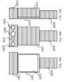
- the ranging camerais placed in camera housing shell 1106 , which can be integrated into the ultrasound probe housing shell 1101 , or can be mounted on it.
- the housing shell comprising the ranging camera and tracking elementsslides into a shoe 1107 on the ultrasound probe housing shell 1101 where it gets fixed with high mechanical registration.
- a board 1108accommodates the ranging and tracking components. There are several components mounted on board 1108 , including: a module that emits ranging signals 1109 , a ranging sensor 1110 , and an IMU 1111 .
- a visor 1012 on the probe housingallows ranging signals (such as IR light) to penetrate into the lenses of the ranging camera 1110 .
- a generic field of view for the ranging sensoris represented by the angle opening 1113 .
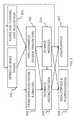
- FIG. 12Bshows a read-out which does not closely integrate the streams from the tracking subsystem and ultrasound probe. This implementation is more suitable when the probe tracking capability and associated methods are implemented to existing ultrasound machines. Such implementation would allow existing ultrasound systems to be fitted with new ultrasound probes that have tracking capability.
- One disadvantage of tele-guided ultrasound functionalityis that a highly trained expert is still required to be available for the investigation.
- An alternative to thatis to have a local computer guidance system that has preloaded procedures for a large array of clinical investigations.
- the patient contour as measured by the ranging or light sensing systemcan be matched to the outline of a generic human model. This will allow the computer guidance system to give precise instructions about the positioning and movement of the ultrasound probe in respect to the real patient model.
- Ultrasound anatomical landmarks observed in real-timecan be matched in 3-D to landmarks in the 3-D models for a much more precise registration that will correct for organ movements and displacements due to variations in body habitus and position.
- An ultrasound image interpretationcan be given by the local user, expert system, or later by a radiologist.
- a “stereotactic ultrasound” instrument as described hereincan allow the user to label features of interest in 3-D, and register them with respect to the patient model so that follow-up investigations can easily use those coordinates to re-evaluate medical conditions.
- the usercan be given software tools to mark features in the 2-D ultrasound scan. Since the ultrasound probe position will be spatially registered to the 3-D model of the patient contour, the marked structure will be registered within the 3-D patient model. Moreover, the positioning of the ultrasound probe with respect to the body can be retained so that it can be reproduced by an operator at a later moment.
- An advantage of the ultrasound systemis that it can be used very efficiently as a “freehand” 3-D ultrasound system.
- a “freehand ultrasound”uses a regular 2-D ultrasound probe as the operator moves it across the body of the patient. Combining successive 2-D ultrasound images, a 3-D model of the whole investigated volume is formed. Since a whole 3-D model will be created by keeping track of all 2-D scans, the final result of the investigation will be practically independent on the skill of the operator to take relevant ultrasound cross-sections, and to notice relevant features.
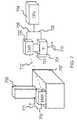
- FIG. 16shows an example of an implementation where the at least one camera or ranging device is mounted on a HMTV system. For clarity, only one sensor probe is shown in this figure.
- a user 1600such as a physician, investigates a object of interest 1601 , such as a patient, using a sensor probe 1602 , such as an ultrasound probe.
- the userwear a head mounted tracking and visualization system (HMTV) 1603 , which comprises a camera system made out of two light sensing devices 1604 and 1605 and a light emitter 1606 , which can be part of a structured light camera, a time of flight camera, a LIDAR sensing camera, or a flash LIDAR camera. More cameras could be used.
- HMTVhead mounted tracking and visualization system
Landscapes
- Health & Medical Sciences (AREA)
- Life Sciences & Earth Sciences (AREA)
- Engineering & Computer Science (AREA)
- Physics & Mathematics (AREA)
- Medical Informatics (AREA)
- Surgery (AREA)
- Veterinary Medicine (AREA)
- Biomedical Technology (AREA)
- Heart & Thoracic Surgery (AREA)
- Animal Behavior & Ethology (AREA)
- General Health & Medical Sciences (AREA)
- Public Health (AREA)
- Molecular Biology (AREA)
- Pathology (AREA)
- Biophysics (AREA)
- Nuclear Medicine, Radiotherapy & Molecular Imaging (AREA)
- Radiology & Medical Imaging (AREA)
- Radar, Positioning & Navigation (AREA)
- Remote Sensing (AREA)
- Computer Networks & Wireless Communication (AREA)
- General Physics & Mathematics (AREA)
- Electromagnetism (AREA)
- Computer Vision & Pattern Recognition (AREA)
- Human Computer Interaction (AREA)
- Acoustics & Sound (AREA)
- High Energy & Nuclear Physics (AREA)
- Optics & Photonics (AREA)
- Oral & Maxillofacial Surgery (AREA)
- Robotics (AREA)
- Dermatology (AREA)
- Anesthesiology (AREA)
- Hematology (AREA)
- Ultra Sonic Daignosis Equipment (AREA)
- Nuclear Medicine (AREA)
- Length Measuring Devices By Optical Means (AREA)
Abstract
Description
Claims (24)
Priority Applications (9)
| Application Number | Priority Date | Filing Date | Title |
|---|---|---|---|
| CN201380022670.7ACN104271046B (en) | 2012-03-07 | 2013-03-07 | Methods and systems for tracking and guiding sensors and instruments |
| CA3228582ACA3228582A1 (en) | 2012-03-07 | 2013-03-07 | Methods and systems for tracking and guiding sensors and instruments |
| CN202111121135.XACN113974689B (en) | 2012-03-07 | 2013-03-07 | Spatial Alignment Equipment |
| PCT/US2013/029710WO2013134559A1 (en) | 2012-03-07 | 2013-03-07 | Methods and systems for tracking and guiding sensors and instruments |
| US13/789,143US9561019B2 (en) | 2012-03-07 | 2013-03-07 | Methods and systems for tracking and guiding sensors and instruments |
| CA2866370ACA2866370C (en) | 2012-03-07 | 2013-03-07 | Methods and systems for tracking and guiding sensors and instruments |
| US15/143,301US10426350B2 (en) | 2012-03-07 | 2016-04-29 | Methods and systems for tracking and guiding sensors and instruments |
| US16/512,835US11678804B2 (en) | 2012-03-07 | 2019-07-16 | Methods and systems for tracking and guiding sensors and instruments |
| US18/309,068US20230389801A1 (en) | 2012-03-07 | 2023-04-28 | Methods and systems for tracking and guiding sensors and instruments |
Applications Claiming Priority (3)
| Application Number | Priority Date | Filing Date | Title |
|---|---|---|---|
| US201261607676P | 2012-03-07 | 2012-03-07 | |
| US201261699750P | 2012-09-11 | 2012-09-11 | |
| US13/789,143US9561019B2 (en) | 2012-03-07 | 2013-03-07 | Methods and systems for tracking and guiding sensors and instruments |
Related Child Applications (1)
| Application Number | Title | Priority Date | Filing Date |
|---|---|---|---|
| US15/143,301DivisionUS10426350B2 (en) | 2012-03-07 | 2016-04-29 | Methods and systems for tracking and guiding sensors and instruments |
Publications (2)
| Publication Number | Publication Date |
|---|---|
| US20130237811A1 US20130237811A1 (en) | 2013-09-12 |
| US9561019B2true US9561019B2 (en) | 2017-02-07 |
Family
ID=49114699
Family Applications (4)
| Application Number | Title | Priority Date | Filing Date |
|---|---|---|---|
| US13/789,143Active2033-09-21US9561019B2 (en) | 2012-03-07 | 2013-03-07 | Methods and systems for tracking and guiding sensors and instruments |
| US15/143,301Active2035-04-03US10426350B2 (en) | 2012-03-07 | 2016-04-29 | Methods and systems for tracking and guiding sensors and instruments |
| US16/512,835Active2035-04-30US11678804B2 (en) | 2012-03-07 | 2019-07-16 | Methods and systems for tracking and guiding sensors and instruments |
| US18/309,068PendingUS20230389801A1 (en) | 2012-03-07 | 2023-04-28 | Methods and systems for tracking and guiding sensors and instruments |
Family Applications After (3)
| Application Number | Title | Priority Date | Filing Date |
|---|---|---|---|
| US15/143,301Active2035-04-03US10426350B2 (en) | 2012-03-07 | 2016-04-29 | Methods and systems for tracking and guiding sensors and instruments |
| US16/512,835Active2035-04-30US11678804B2 (en) | 2012-03-07 | 2019-07-16 | Methods and systems for tracking and guiding sensors and instruments |
| US18/309,068PendingUS20230389801A1 (en) | 2012-03-07 | 2023-04-28 | Methods and systems for tracking and guiding sensors and instruments |
Country Status (5)
| Country | Link |
|---|---|
| US (4) | US9561019B2 (en) |
| EP (2) | EP2822472B1 (en) |
| CN (3) | CN104271046B (en) |
| CA (2) | CA2866370C (en) |
| WO (1) | WO2013134559A1 (en) |
Cited By (52)
| Publication number | Priority date | Publication date | Assignee | Title |
|---|---|---|---|---|
| US20150278689A1 (en)* | 2014-03-31 | 2015-10-01 | Gary Stephen Shuster | Systems, Devices And Methods For Improved Visualization And Control Of Remote Objects |
| US20180025666A1 (en)* | 2016-07-21 | 2018-01-25 | Auris Surgical Robotics, Inc. | System with emulator movement tracking for controlling medical devices |
| US20190004619A1 (en)* | 2017-06-30 | 2019-01-03 | Hilti Aktiengesellschaft | System and Method for Measuring Position and Orientation of a Rigid Body |
| US10236080B2 (en)* | 2013-06-28 | 2019-03-19 | Elwha Llc | Patient medical support system and related method |
| US10426350B2 (en) | 2012-03-07 | 2019-10-01 | Ziteo, Inc. | Methods and systems for tracking and guiding sensors and instruments |
| US10617401B2 (en) | 2014-11-14 | 2020-04-14 | Ziteo, Inc. | Systems for localization of targets inside a body |
| US10635758B2 (en) | 2016-07-15 | 2020-04-28 | Fastbrick Ip Pty Ltd | Brick/block laying machine incorporated in a vehicle |
| US10675101B2 (en) | 2013-03-15 | 2020-06-09 | Auris Health, Inc. | User interface for active drive apparatus with finite range of motion |
| US10688283B2 (en) | 2013-03-13 | 2020-06-23 | Auris Health, Inc. | Integrated catheter and guide wire controller |
| US10739439B2 (en)* | 2018-05-04 | 2020-08-11 | Industrial Technology Research Institute | Laser positioning system and position measuring method using the same |
| US10776954B2 (en) | 2018-10-08 | 2020-09-15 | Microsoft Technology Licensing, Llc | Real-world anchor in a virtual-reality environment |
| KR20200117522A (en)* | 2019-04-04 | 2020-10-14 | 경북대학교 산학협력단 | Shape restoration device and method using ultrasonic probe |
| US10835153B2 (en) | 2017-12-08 | 2020-11-17 | Auris Health, Inc. | System and method for medical instrument navigation and targeting |
| US10849702B2 (en) | 2013-03-15 | 2020-12-01 | Auris Health, Inc. | User input devices for controlling manipulation of guidewires and catheters |
| US10865578B2 (en) | 2016-07-15 | 2020-12-15 | Fastbrick Ip Pty Ltd | Boom for material transport |
| US10912924B2 (en) | 2014-03-24 | 2021-02-09 | Auris Health, Inc. | Systems and devices for catheter driving instinctiveness |
| US11020016B2 (en) | 2013-05-30 | 2021-06-01 | Auris Health, Inc. | System and method for displaying anatomy and devices on a movable display |
| US20210212668A1 (en)* | 2018-05-22 | 2021-07-15 | The Board Of Trustees Of The Leland Stanford Junior University | Combined frequency and angle compounding for speckle reduction in ultrasound imaging |
| US20210212792A1 (en)* | 2019-12-30 | 2021-07-15 | Ethicon Llc | System and method for determining, adjusting, and managing resection margin about a subject tissue |
| US11150747B2 (en) | 2018-05-25 | 2021-10-19 | Hottinger Brüel & Kjær A/S | Method of determining spatial configurations of a plurality of transducers relative to a target object |
| WO2021211570A1 (en)* | 2020-04-13 | 2021-10-21 | Washington University | System and method for augmented reality data interaction for ultrasound imaging |
| US11179213B2 (en) | 2018-05-18 | 2021-11-23 | Auris Health, Inc. | Controllers for robotically-enabled teleoperated systems |
| US11219501B2 (en) | 2019-12-30 | 2022-01-11 | Cilag Gmbh International | Visualization systems using structured light |
| US20220054200A1 (en)* | 2018-12-26 | 2022-02-24 | Beijing Yakebot Technology Co., Ltd | Calibration method and device for dental implant navigation surgery, and tracking method and device for dental implant navigation surgery |
| US11259793B2 (en) | 2018-07-16 | 2022-03-01 | Cilag Gmbh International | Operative communication of light |
| US11284963B2 (en) | 2019-12-30 | 2022-03-29 | Cilag Gmbh International | Method of using imaging devices in surgery |
| WO2022139052A1 (en)* | 2020-09-21 | 2022-06-30 | 주식회사 부명 | Electronic device and method for controlling ultrasound scanner |
| US11401115B2 (en) | 2017-10-11 | 2022-08-02 | Fastbrick Ip Pty Ltd | Machine for conveying objects and multi-bay carousel for use therewith |
| US11426142B2 (en)* | 2018-08-13 | 2022-08-30 | Rutgers, The State University Of New Jersey | Computer vision systems and methods for real-time localization of needles in ultrasound images |
| US11439358B2 (en) | 2019-04-09 | 2022-09-13 | Ziteo, Inc. | Methods and systems for high performance and versatile molecular imaging |
| US11441899B2 (en) | 2017-07-05 | 2022-09-13 | Fastbrick Ip Pty Ltd | Real time position and orientation tracker |
| US11638569B2 (en) | 2018-06-08 | 2023-05-02 | Rutgers, The State University Of New Jersey | Computer vision systems and methods for real-time needle detection, enhancement and localization in ultrasound |
| US11648060B2 (en) | 2019-12-30 | 2023-05-16 | Cilag Gmbh International | Surgical system for overlaying surgical instrument data onto a virtual three dimensional construct of an organ |
| US11656357B2 (en) | 2017-08-17 | 2023-05-23 | Fastbrick Ip Pty Ltd | Laser tracker with improved roll angle measurement |
| WO2023148720A1 (en)* | 2022-02-03 | 2023-08-10 | Mazor Robotics Ltd. | Segemental tracking combining optical tracking and inertial measurements |
| US11744667B2 (en) | 2019-12-30 | 2023-09-05 | Cilag Gmbh International | Adaptive visualization by a surgical system |
| US11759284B2 (en) | 2019-12-30 | 2023-09-19 | Cilag Gmbh International | Surgical systems for generating three dimensional constructs of anatomical organs and coupling identified anatomical structures thereto |
| US11832996B2 (en) | 2019-12-30 | 2023-12-05 | Cilag Gmbh International | Analyzing surgical trends by a surgical system |
| US11850104B2 (en) | 2019-12-30 | 2023-12-26 | Cilag Gmbh International | Surgical imaging system |
| US11872007B2 (en) | 2019-06-28 | 2024-01-16 | Auris Health, Inc. | Console overlay and methods of using same |
| US11911213B2 (en) | 2019-06-03 | 2024-02-27 | General Electric Company | Techniques for determining ultrasound probe motion |
| US11958193B2 (en) | 2017-08-17 | 2024-04-16 | Fastbrick Ip Pty Ltd | Communication system for an interaction system |
| US20240153292A1 (en)* | 2021-03-01 | 2024-05-09 | TiHive | Personalized authentication of products using terahertz waves |
| US12002571B2 (en) | 2019-12-30 | 2024-06-04 | Cilag Gmbh International | Dynamic surgical visualization systems |
| US12053223B2 (en) | 2019-12-30 | 2024-08-06 | Cilag Gmbh International | Adaptive surgical system control according to surgical smoke particulate characteristics |
| WO2024173991A1 (en)* | 2023-02-22 | 2024-08-29 | Vause Medical Pty Ltd | Method and system for providing guidance to a user performing a medical procedure |
| US12207881B2 (en) | 2019-12-30 | 2025-01-28 | Cilag Gmbh International | Surgical systems correlating visualization data and powered surgical instrument data |
| US12214500B2 (en) | 2018-07-16 | 2025-02-04 | Fastbrick Ip Pty Ltd | Backup tracking for an interaction system |
| US12257013B2 (en) | 2019-03-15 | 2025-03-25 | Cilag Gmbh International | Robotic surgical systems with mechanisms for scaling camera magnification according to proximity of surgical tool to tissue |
| US12311546B2 (en) | 2018-07-16 | 2025-05-27 | Fastbrick Ip Pty Ltd | Active damping system |
| US12385265B2 (en) | 2020-04-22 | 2025-08-12 | Fastbrick Ip Pty Ltd | Block transfer apparatus and improved clamping assembly for use therewith |
| US12398574B2 (en) | 2020-07-08 | 2025-08-26 | Fastbrick Ip Pty Ltd | Adhesive application system |
Families Citing this family (228)
| Publication number | Priority date | Publication date | Assignee | Title |
|---|---|---|---|---|
| PL2023812T3 (en) | 2006-05-19 | 2017-07-31 | The Queen's Medical Center | Motion tracking system for real time adaptive imaging and spectroscopy |
| JP5868005B2 (en)* | 2011-02-04 | 2016-02-24 | キヤノン株式会社 | Imaging apparatus, imaging condition setting method, program |
| WO2013032933A2 (en) | 2011-08-26 | 2013-03-07 | Kinecticor, Inc. | Methods, systems, and devices for intra-scan motion correction |
| US8900125B2 (en)* | 2012-03-12 | 2014-12-02 | United Sciences, Llc | Otoscanning with 3D modeling |
| US9474505B2 (en)* | 2012-03-16 | 2016-10-25 | Toshiba Medical Systems Corporation | Patient-probe-operator tracking method and apparatus for ultrasound imaging systems |
| US9877699B2 (en) | 2012-03-26 | 2018-01-30 | Teratech Corporation | Tablet ultrasound system |
| US10667790B2 (en) | 2012-03-26 | 2020-06-02 | Teratech Corporation | Tablet ultrasound system |
| US9472005B1 (en)* | 2012-04-18 | 2016-10-18 | Amazon Technologies, Inc. | Projection and camera system for augmented reality environment |
| CN104135939B (en)* | 2012-09-06 | 2016-08-17 | 东芝医疗系统株式会社 | Diagnostic ultrasound equipment and medical image projection arrangement |
| US20140132729A1 (en)* | 2012-11-15 | 2014-05-15 | Cybernet Systems Corporation | Method and apparatus for camera-based 3d flaw tracking system |
| CN109008972A (en) | 2013-02-01 | 2018-12-18 | 凯内蒂科尔股份有限公司 | The motion tracking system of real-time adaptive motion compensation in biomedical imaging |
| HK1218669A1 (en)* | 2013-02-04 | 2017-03-03 | Novadaq Technologies Inc. | Combined radiationless automated three dimensional patient habitus imaging with scintigraphy |
| US20140270477A1 (en)* | 2013-03-14 | 2014-09-18 | Jonathan Coon | Systems and methods for displaying a three-dimensional model from a photogrammetric scan |
| US20140267660A1 (en)* | 2013-03-15 | 2014-09-18 | Fujifilm Sonosite, Inc. | Ultrasound device with video display capability and associated devices, systems, and methods |
| KR20140121581A (en)* | 2013-04-08 | 2014-10-16 | 삼성전자주식회사 | Surgical robot system |
| KR20140126473A (en)* | 2013-04-23 | 2014-10-31 | 삼성전자주식회사 | Marker and method for estimating surgical instrument pose using the same |
| KR101563498B1 (en)* | 2013-05-02 | 2015-10-27 | 삼성메디슨 주식회사 | Ultrasound system and method for providing change information of target object |
| WO2014186611A2 (en)* | 2013-05-15 | 2014-11-20 | Massachusetts Institute Of Technology | Refractive flow measurement system |
| US9285894B1 (en)* | 2013-05-24 | 2016-03-15 | Amazon Technologies, Inc. | Multi-path reduction for optical time-of-flight |
| EP3001219B1 (en)* | 2013-08-20 | 2019-10-02 | CureFab Technologies GmbH | Optical tracking |
| US9370372B2 (en) | 2013-09-04 | 2016-06-21 | Mcginley Engineered Solutions, Llc | Drill bit penetration measurement systems and methods |
| TWI499966B (en)* | 2013-10-08 | 2015-09-11 | Univ Nat Taiwan Science Tech | Interactive operation method of electronic apparatus |
| US9404904B2 (en)* | 2013-11-05 | 2016-08-02 | The Boeing Company | Methods and systems for non-destructive inspection |
| WO2015070159A1 (en) | 2013-11-08 | 2015-05-14 | Mcginley Engineered Solutions, Llc. | Surgical saw with sensing technology for determining cut through of bone and depth of the saw blade during surgery |
| US10835203B2 (en)* | 2013-11-11 | 2020-11-17 | Acessa Health Inc. | System for visualization and control of surgical devices utilizing a graphical user interface |
| US20150130592A1 (en)* | 2013-11-13 | 2015-05-14 | Symbol Technologies. Inc. | Package-loading system |
| US9622720B2 (en)* | 2013-11-27 | 2017-04-18 | Clear Guide Medical, Inc. | Ultrasound system with stereo image guidance or tracking |
| JP6206155B2 (en)* | 2013-12-16 | 2017-10-04 | コニカミノルタ株式会社 | Ultrasonic diagnostic equipment |
| US12357274B2 (en) | 2013-12-20 | 2025-07-15 | Raghu Raghavan | Systems and methods for acquiring ultrasonic data |
| WO2015095715A1 (en)* | 2013-12-20 | 2015-06-25 | Intuitive Surgical Operations, Inc. | Simulator system for medical procedure training |
| EP3110335B1 (en)* | 2014-02-28 | 2022-09-07 | Koninklijke Philips N.V. | Zone visualization for ultrasound-guided procedures |
| DE102014104802A1 (en)* | 2014-04-03 | 2015-10-08 | Aesculap Ag | Medical referencing device, medical navigation system and method |
| KR102258800B1 (en)* | 2014-05-15 | 2021-05-31 | 삼성메디슨 주식회사 | Ultrasound diagnosis apparatus and mehtod thereof |
| DE102014108129A1 (en)* | 2014-06-10 | 2015-12-17 | Aesculap Ag | Medical instrumentation, use of a medical navigation system and method |
| JP5915949B2 (en)* | 2014-06-25 | 2016-05-11 | パナソニックIpマネジメント株式会社 | Projection system |
| US9626764B2 (en)* | 2014-07-01 | 2017-04-18 | Castar, Inc. | System and method for synchronizing fiducial markers |
| EP3188660A4 (en) | 2014-07-23 | 2018-05-16 | Kineticor, Inc. | Systems, devices, and methods for tracking and compensating for patient motion during a medical imaging scan |
| KR20160014242A (en)* | 2014-07-29 | 2016-02-11 | 삼성전자주식회사 | Method and device for mapping location of sensor and event operation with monitoring device |
| US9612316B1 (en)* | 2014-07-31 | 2017-04-04 | Sandia Corporation | Correlation and 3D-tracking of objects by pointing sensors |
| EP3188671A4 (en) | 2014-09-05 | 2018-03-14 | Mcginley Engineered Solutions LLC | Instrument leading edge measurement system and method |
| US10070120B2 (en)* | 2014-09-17 | 2018-09-04 | Qualcomm Incorporated | Optical see-through display calibration |
| US20160097868A1 (en)* | 2014-10-02 | 2016-04-07 | Source Production & Equipment Co., Inc. | Radiation surveying |
| US10136915B2 (en)* | 2015-01-26 | 2018-11-27 | Loving Heart Medical Technology Inc. | Ultrasound needle guide apparatus |
| JP2018516718A (en)* | 2015-03-01 | 2018-06-28 | アリス エムディー, インコーポレイテッドARIS MD, Inc. | Morphological diagnosis of extended reality |
| US9519949B2 (en)* | 2015-03-13 | 2016-12-13 | Koninklijke Philips N.V. | Determining transformation between different coordinate systems |
| US20160324580A1 (en)* | 2015-03-23 | 2016-11-10 | Justin Esterberg | Systems and methods for assisted surgical navigation |
| GB2536650A (en) | 2015-03-24 | 2016-09-28 | Augmedics Ltd | Method and system for combining video-based and optic-based augmented reality in a near eye display |
| EP3273894B1 (en)* | 2015-03-26 | 2023-03-15 | Biomet Manufacturing, LLC | Anatomic registration probes, systems and methods |
| EP3283994A4 (en) | 2015-04-17 | 2018-12-19 | Tulip Interfaces Inc. | Monitoring tool usage |
| US20160317122A1 (en)* | 2015-04-28 | 2016-11-03 | Qualcomm Incorporated | In-device fusion of optical and inertial positional tracking of ultrasound probes |
| CN114376733B (en) | 2015-06-09 | 2025-01-10 | 直观外科手术操作公司 | Configuring surgical systems using surgical procedure atlases |
| EP3104118B1 (en)* | 2015-06-12 | 2019-02-27 | Hexagon Technology Center GmbH | Method to control a drive mechanism of an automated machine having a camera |
| US10512508B2 (en)* | 2015-06-15 | 2019-12-24 | The University Of British Columbia | Imagery system |
| DE102015211965A1 (en)* | 2015-06-26 | 2016-12-29 | Siemens Healthcare Gmbh | Non-contact device control in the medical sterile field |
| US10268781B2 (en)* | 2015-07-01 | 2019-04-23 | Paddy Dunning | Visual modeling apparatuses, methods and systems |
| US9940542B2 (en) | 2015-08-11 | 2018-04-10 | Google Llc | Managing feature data for environment mapping on an electronic device |
| US10335115B2 (en)* | 2015-09-03 | 2019-07-02 | Siemens Healthcare Gmbh | Multi-view, multi-source registration of moving anatomies and devices |
| US10261185B2 (en)* | 2015-09-04 | 2019-04-16 | Bin Lu | System and method for remotely measuring distances between two points |
| CN114896015B (en)* | 2015-09-23 | 2025-03-21 | 尹特根埃克斯有限公司 | System and method for real-time assistance |
| US10390869B2 (en) | 2015-10-27 | 2019-08-27 | Mcginley Engineered Solutions, Llc | Techniques and instruments for placement of orthopedic implants relative to bone features |
| JP6636629B2 (en)* | 2015-10-29 | 2020-01-29 | コーニンクレッカ フィリップス エヌ ヴェKoninklijke Philips N.V. | Remote assistance workstation, method, and system with user interface for remotely assisting spatial placement tasks via augmented reality glasses |
| US10321920B2 (en) | 2015-11-06 | 2019-06-18 | Mcginley Engineered Solutions, Llc | Measurement system for use with surgical burr instrument |
| WO2017079732A1 (en)* | 2015-11-07 | 2017-05-11 | Ji-Xin Cheng | An intraoperative optoacoustic guide apparatus and method |
| EP3373834A4 (en) | 2015-11-12 | 2019-07-31 | Intuitive Surgical Operations Inc. | Surgical system with training or assist functions |
| US20180045960A1 (en) | 2015-12-02 | 2018-02-15 | Augmenteum, LLC. | System for and method of projecting augmentation imagery in a head-mounted display |
| CN105395252A (en)* | 2015-12-10 | 2016-03-16 | 哈尔滨工业大学 | Wearable 3D image navigation device for vascular interventional surgery with human-computer interaction |
| US10930007B2 (en)* | 2015-12-14 | 2021-02-23 | Koninklijke Philips N.V. | System and method for medical device tracking |
| US10338225B2 (en)* | 2015-12-15 | 2019-07-02 | Uber Technologies, Inc. | Dynamic LIDAR sensor controller |
| CA3012322A1 (en)* | 2016-01-26 | 2017-08-03 | The Regents Of The University Of California | System for out of bore focal laser therapy |
| US9568612B1 (en)* | 2016-02-25 | 2017-02-14 | King Saud University | 3D image generation with position-sensing gamma probe |
| US11064904B2 (en) | 2016-02-29 | 2021-07-20 | Extremity Development Company, Llc | Smart drill, jig, and method of orthopedic surgery |
| AU2017227708A1 (en) | 2016-03-01 | 2018-10-18 | ARIS MD, Inc. | Systems and methods for rendering immersive environments |
| US20190090955A1 (en)* | 2016-03-01 | 2019-03-28 | Mirus Llc | Systems and methods for position and orientation tracking of anatomy and surgical instruments |
| CA3017983A1 (en) | 2016-03-14 | 2017-09-21 | Mohamed R. Mahfouz | Ultra-wideband positioning for wireless ultrasound tracking and communication |
| US20170273665A1 (en)* | 2016-03-28 | 2017-09-28 | Siemens Medical Solutions Usa, Inc. | Pose Recovery of an Ultrasound Transducer |
| EP3179450B1 (en)* | 2016-04-12 | 2020-09-09 | Siemens Healthcare GmbH | Method and system for multi sensory representation of an object |
| EP3445249B1 (en)* | 2016-04-19 | 2020-04-15 | Koninklijke Philips N.V. | Ultrasound imaging probe positioning |
| US20170303859A1 (en)* | 2016-04-26 | 2017-10-26 | Kineticor, Inc. | Systems, devices, and methods for tracking and compensating for patient motion during a medical imaging scan |
| WO2017205978A1 (en) | 2016-05-31 | 2017-12-07 | Holdsworth David W | Gamma probe and multimodal intraoperative imaging system |
| CN109310399B (en)* | 2016-06-06 | 2022-12-06 | 皇家飞利浦有限公司 | Medical ultrasonic image processing apparatus |
| EP4201340A1 (en)* | 2016-06-20 | 2023-06-28 | BFLY Operations, Inc. | Automated image acquisition for assisting a user to operate an ultrasound device |
| WO2017219090A1 (en)* | 2016-06-22 | 2017-12-28 | Imdex Global B.V. | System and method for acquiring and transferring data pertaining to a borehole core |
| GB201611429D0 (en)* | 2016-06-30 | 2016-08-17 | Create Tech Ltd | Portable survey meter and method |
| CN106236281A (en)* | 2016-07-25 | 2016-12-21 | 上海市肺科医院 | A kind of operating room three-dimensional visualization operating system |
| US10398514B2 (en) | 2016-08-16 | 2019-09-03 | Insight Medical Systems, Inc. | Systems and methods for sensory augmentation in medical procedures |
| ES2992065T3 (en)* | 2016-08-16 | 2024-12-09 | Insight Medical Systems Inc | Sensory augmentation systems in medical procedures |
| US20180049622A1 (en)* | 2016-08-16 | 2018-02-22 | Insight Medical Systems, Inc. | Systems and methods for sensory augmentation in medical procedures |
| US10695134B2 (en)* | 2016-08-25 | 2020-06-30 | Verily Life Sciences Llc | Motion execution of a robotic system |
| US11839433B2 (en)* | 2016-09-22 | 2023-12-12 | Medtronic Navigation, Inc. | System for guided procedures |
| US20220008141A1 (en)* | 2016-10-04 | 2022-01-13 | Petal Surgical, Inc. | Enhanced reality medical guidance systems and methods of use |
| US20180092698A1 (en)* | 2016-10-04 | 2018-04-05 | WortheeMed, Inc. | Enhanced Reality Medical Guidance Systems and Methods of Use |
| WO2018094118A1 (en)* | 2016-11-16 | 2018-05-24 | Teratech Corporation | Portable ultrasound system |
| US10422886B1 (en)* | 2016-11-17 | 2019-09-24 | Clinitraq | Real-time location aware radiation system and method for use thereof |
| TWI634343B (en)* | 2016-11-21 | 2018-09-01 | 宏達國際電子股份有限公司 | Positioning device and positioning method |
| US9638800B1 (en) | 2016-11-22 | 2017-05-02 | 4Sense, Inc. | Passive tracking system |
| US9720086B1 (en) | 2016-11-22 | 2017-08-01 | 4Sense, Inc. | Thermal- and modulated-light-based passive tracking system |
| US11056022B1 (en)* | 2016-11-29 | 2021-07-06 | Sproutel, Inc. | System, apparatus, and method for creating an interactive augmented reality experience to simulate medical procedures for pediatric disease education |
| US10748450B1 (en)* | 2016-11-29 | 2020-08-18 | Sproutel, Inc. | System, apparatus, and method for creating an interactive augmented reality experience to simulate medical procedures for pediatric disease education |
| US20210327303A1 (en)* | 2017-01-24 | 2021-10-21 | Tienovix, Llc | System and method for augmented reality guidance for use of equipment systems |
| US20210327304A1 (en)* | 2017-01-24 | 2021-10-21 | Tienovix, Llc | System and method for augmented reality guidance for use of equpment systems |
| EP3574504A1 (en)* | 2017-01-24 | 2019-12-04 | Tietronix Software, Inc. | System and method for three-dimensional augmented reality guidance for use of medical equipment |
| US20210295048A1 (en)* | 2017-01-24 | 2021-09-23 | Tienovix, Llc | System and method for augmented reality guidance for use of equipment systems |
| DE102017202517A1 (en)* | 2017-02-16 | 2018-08-16 | Siemens Healthcare Gmbh | Operating device and operating method for operating a medical device |
| DE102017203438B4 (en)* | 2017-03-02 | 2025-02-13 | Siemens Healthineers Ag | Method for image support of a person performing a minimally invasive procedure with an instrument in an intervention area of a patient, X-ray device, computer program and electronically readable data carrier |
| SG11201908231XA (en) | 2017-03-06 | 2019-10-30 | Gelsight Inc | Surface topography measurement systems |
| EP3398519A1 (en) | 2017-05-02 | 2018-11-07 | Koninklijke Philips N.V. | Determining a guidance signal and a system for providing a guidance for an ultrasonic handheld transducer |
| US10510161B2 (en) | 2017-03-24 | 2019-12-17 | Varian Medical Systems, Inc. | Patient-mounted or patient support-mounted camera for position monitoring during medical procedures |
| US10444506B2 (en) | 2017-04-03 | 2019-10-15 | Microsoft Technology Licensing, Llc | Mixed reality measurement with peripheral tool |
| EP3385912B1 (en)* | 2017-04-06 | 2022-08-24 | Hexagon Technology Center GmbH | Near field manoeuvring for ar-devices using image tracking |
| IT201700047233A1 (en)* | 2017-05-02 | 2018-11-02 | Ids Georadar S R L | Method perfected for the execution of georadar surveys and related equipment |
| US11647983B2 (en)* | 2017-05-05 | 2023-05-16 | International Business Machines Corporation | Automating ultrasound examination of a vascular system |
| US11583222B2 (en)* | 2017-05-19 | 2023-02-21 | Covidien Lp | Systems, devices, and methods for lymph specimen tracking, drainage determination, visualization, and treatment |
| US10432913B2 (en) | 2017-05-31 | 2019-10-01 | Proximie, Inc. | Systems and methods for determining three dimensional measurements in telemedicine application |
| WO2018222181A1 (en)* | 2017-05-31 | 2018-12-06 | Proximie Inc. | Systems and methods for determining three dimensional measurements in telemedicine application |
| US11393562B2 (en) | 2017-06-07 | 2022-07-19 | Koninklijke Philips N.V. | Device, system, and method for operative personal health records |
| JP7226827B2 (en)* | 2017-06-15 | 2023-02-21 | コンセッホ スペリオル デ インベスティガシオンス サイエンティフィカス(シーエスアイシー) | System for generating first and second images of a subject and method of operating the system |
| US11164679B2 (en) | 2017-06-20 | 2021-11-02 | Advinow, Inc. | Systems and methods for intelligent patient interface exam station |
| US10216265B1 (en)* | 2017-08-07 | 2019-02-26 | Rockwell Collins, Inc. | System and method for hybrid optical/inertial headtracking via numerically stable Kalman filter |
| AU2018214021A1 (en)* | 2017-08-10 | 2019-02-28 | Biosense Webster (Israel) Ltd. | Method and apparatus for performing facial registration |
| AU2018321969B2 (en) | 2017-08-25 | 2022-08-11 | Mcginley Engineered Solutions, Llc | Sensing of surgical instrument placement relative to anatomic structures |
| US10772703B2 (en)* | 2017-08-25 | 2020-09-15 | Titan Medical Inc. | Methods and apparatuses for positioning a camera of a surgical robotic system to capture images inside a body cavity of a patient during a medical procedure |
| WO2019046825A1 (en)* | 2017-08-31 | 2019-03-07 | The Regents Of The University Of California | Enhanced ultrasound systems and methods |
| JP2020534051A (en) | 2017-09-14 | 2020-11-26 | ニューラル アナリティクス、インコーポレイテッド | Systems and methods for aligning headset systems |
| US10806525B2 (en) | 2017-10-02 | 2020-10-20 | Mcginley Engineered Solutions, Llc | Surgical instrument with real time navigation assistance |
| DE102017126487B4 (en)* | 2017-11-02 | 2022-05-25 | Festool Gmbh | System with an optical and/or mechanical reference for processing a workpiece |
| JP7065592B2 (en)* | 2017-11-17 | 2022-05-12 | 日本光電工業株式会社 | Ultrasonic probe, ultrasonic measurement system |
| US10816334B2 (en) | 2017-12-04 | 2020-10-27 | Microsoft Technology Licensing, Llc | Augmented reality measurement and schematic system including tool having relatively movable fiducial markers |
| CN107928805B (en)* | 2017-12-06 | 2019-04-26 | 上海波城医疗科技有限公司 | Ultrasonic scanning space positioning system and method |
| US20190175059A1 (en) | 2017-12-07 | 2019-06-13 | Medtronic Xomed, Inc. | System and Method for Assisting Visualization During a Procedure |
| US10546419B2 (en)* | 2018-02-14 | 2020-01-28 | Faro Technologies, Inc. | System and method of on-site documentation enhancement through augmented reality |
| US10935374B2 (en) | 2018-02-21 | 2021-03-02 | Faro Technologies, Inc. | Systems and methods for generating models of scanned environments |
| US10521916B2 (en) | 2018-02-21 | 2019-12-31 | Covidien Lp | Locating tumors using structured light scanning |
| KR20200125658A (en)* | 2018-02-27 | 2020-11-04 | 버터플라이 네트워크, 인크. | Methods and apparatus for telemedicine |
| US10939806B2 (en)* | 2018-03-06 | 2021-03-09 | Advinow, Inc. | Systems and methods for optical medical instrument patient measurements |
| US11348688B2 (en) | 2018-03-06 | 2022-05-31 | Advinow, Inc. | Systems and methods for audio medical instrument patient measurements |
| DE102018109250A1 (en)* | 2018-04-18 | 2019-10-24 | INOEX GmbH Innovationen und Ausrüstungen für die Extrusionstechnik | Method and THz measuring device for measuring a measurement object with electromagnetic radiation |
| US11980507B2 (en) | 2018-05-02 | 2024-05-14 | Augmedics Ltd. | Registration of a fiducial marker for an augmented reality system |
| US10650603B2 (en)* | 2018-05-03 | 2020-05-12 | Microsoft Technology Licensing, Llc | Representation of user position, movement, and gaze in mixed reality space |
| US10825563B2 (en)* | 2018-05-14 | 2020-11-03 | Novarad Corporation | Aligning image data of a patient with actual views of the patient using an optical code affixed to the patient |
| US11783464B2 (en)* | 2018-05-18 | 2023-10-10 | Lawrence Livermore National Security, Llc | Integrating extended reality with inspection systems |
| US11497563B2 (en) | 2018-06-15 | 2022-11-15 | Koninklijke Philips N.V. | Synchronized tracking of multiple interventional medical devices |
| US10754419B2 (en) | 2018-07-12 | 2020-08-25 | Google Llc | Hybrid pose tracking system with electromagnetic position tracking |
| EP3837631A1 (en)* | 2018-08-17 | 2021-06-23 | 3M Innovative Properties Company | Structured texture embeddings in pathway articles for machine recognition |
| WO2020041177A1 (en) | 2018-08-20 | 2020-02-27 | Butterfly Network, Inc. | Methods and apparatuses for guiding collection of ultrasound data |
| CN109345632B (en)* | 2018-09-17 | 2023-04-07 | 深圳达闼科技控股有限公司 | Method for acquiring image, related device and readable storage medium |
| US10939977B2 (en) | 2018-11-26 | 2021-03-09 | Augmedics Ltd. | Positioning marker |
| US11766296B2 (en) | 2018-11-26 | 2023-09-26 | Augmedics Ltd. | Tracking system for image-guided surgery |
| WO2020140042A1 (en)* | 2018-12-28 | 2020-07-02 | Activ Surgical, Inc. | User interface elements for orientation of remote camera during surgery |
| EP3909039A4 (en)* | 2019-01-07 | 2022-10-05 | Butterfly Network, Inc. | METHOD AND DEVICE FOR TELEMEDICINE |
| US20200214672A1 (en)* | 2019-01-07 | 2020-07-09 | Butterfly Network, Inc. | Methods and apparatuses for collection of ultrasound data |
| WO2020146244A1 (en) | 2019-01-07 | 2020-07-16 | Butterfly Network, Inc. | Methods and apparatuses for ultrasound data collection |
| CN113518910B (en) | 2019-01-17 | 2025-08-05 | 莫勒库莱特股份有限公司 | Modular system for multimodal imaging and analysis |
| AU2020209276A1 (en)* | 2019-01-17 | 2021-08-26 | Sbi Alapharma Canada, Inc. | Devices, systems, and methods for tumor visualization and removal |
| CN109840943B (en)* | 2019-01-25 | 2021-06-22 | 天津大学 | 3D visualization analysis method and system |
| US12349982B2 (en) | 2019-02-21 | 2025-07-08 | Surgical Targeted Solutions Inc. | Instrument bourne optical time of flight kinematic position sensing system for precision targeting and methods of surgery |
| KR102729066B1 (en)* | 2019-02-26 | 2024-11-13 | 삼성메디슨 주식회사 | Ultrasound diagnosis apparatus for registrating an ultrasound image and other modality image and method for operating the same |
| JP2022527360A (en)* | 2019-04-04 | 2022-06-01 | センターライン バイオメディカル,インコーポレイテッド | Registration between spatial tracking system and augmented reality display |
| CA3076342A1 (en)* | 2019-04-24 | 2020-10-24 | The Boeing Company | Aligning sensors on vehicles using sensor output |
| US12048487B2 (en)* | 2019-05-06 | 2024-07-30 | Biosense Webster (Israel) Ltd. | Systems and methods for improving cardiac ablation procedures |
| US10881353B2 (en)* | 2019-06-03 | 2021-01-05 | General Electric Company | Machine-guided imaging techniques |
| US10854016B1 (en) | 2019-06-20 | 2020-12-01 | Procore Technologies, Inc. | Computer system and method for creating an augmented environment using QR tape |
| KR102285007B1 (en)* | 2019-06-21 | 2021-08-03 | 주식회사 데카사이트 | Apparatus and method for providing ultrasound image using tracing position and pose of probe in ultrasound scanner |
| EP3986279A4 (en)* | 2019-06-24 | 2023-06-28 | Dm1 Llc | Optical system and apparatus for instrument projection and tracking |
| CN112137722B (en)* | 2019-06-26 | 2024-06-07 | 格罗伯斯医疗有限公司 | Surgical robotic systems, methods, and devices |
| US12178666B2 (en) | 2019-07-29 | 2024-12-31 | Augmedics Ltd. | Fiducial marker |
| US11980506B2 (en) | 2019-07-29 | 2024-05-14 | Augmedics Ltd. | Fiducial marker |
| CN110313939B (en)* | 2019-08-01 | 2020-12-11 | 无锡海斯凯尔医学技术有限公司 | Tissue region-of-interest positioning method, device, equipment and storage medium |
| US11529180B2 (en) | 2019-08-16 | 2022-12-20 | Mcginley Engineered Solutions, Llc | Reversible pin driver |
| TWI852356B (en)* | 2019-09-10 | 2024-08-11 | 浩宇生醫股份有限公司 | Ultrasound imaging system |
| TW202110404A (en)* | 2019-09-10 | 2021-03-16 | 長庚大學 | Ultrasonic image system enables the processing unit to obtain correspondingly two-dimensional ultrasonic image when the ultrasonic probe is at different inclination angles |
| US11181379B2 (en)* | 2019-09-12 | 2021-11-23 | Robert Bosch Gmbh | System and method for enhancing non-inertial tracking system with inertial constraints |
| CN112568935B (en)* | 2019-09-29 | 2024-06-25 | 中慧医学成像有限公司 | Three-dimensional ultrasonic imaging method and system based on three-dimensional tracking camera |
| WO2021072041A1 (en)* | 2019-10-08 | 2021-04-15 | Smith & Nephew, Inc. | Methods for improved ultrasound imaging to emphasize structures of interest and devices thereof |
| US11176746B2 (en)* | 2019-11-08 | 2021-11-16 | Msg Entertainment Group, Llc | Modulated display AR tracking systems and methods |
| EP4072426B1 (en)* | 2019-12-13 | 2025-04-16 | Smith&Nephew, Inc. | Anatomical feature extraction and presentation using augmented reality |
| US11382712B2 (en)* | 2019-12-22 | 2022-07-12 | Augmedics Ltd. | Mirroring in image guided surgery |
| WO2021138262A1 (en)* | 2019-12-30 | 2021-07-08 | Intuitive Surgical Operations, Inc. | Systems and methods for telestration with spatial memory |
| CN110974299A (en)* | 2019-12-31 | 2020-04-10 | 上海杏脉信息科技有限公司 | Ultrasonic scanning robot system, ultrasonic scanning method and medium |
| WO2021150846A1 (en)* | 2020-01-22 | 2021-07-29 | Visualize K.K. | Methods and systems for obtaining a scale reference and measurements of 3d objects from 2d photos |
| US11623086B2 (en) | 2020-01-24 | 2023-04-11 | Medtronic Xomed, Inc. | System and method for therapy |
| US11167127B2 (en) | 2020-01-24 | 2021-11-09 | Medtronic Xomed, Inc. | System and method for therapy |
| US11167140B2 (en) | 2020-01-24 | 2021-11-09 | Medtronic Xomed, Inc. | System and method for therapy |
| US11666755B2 (en) | 2020-01-24 | 2023-06-06 | Medtronic Xomed, Inc. | System and method for therapy |
| US11536843B2 (en)* | 2020-02-08 | 2022-12-27 | The Boeing Company | De-jitter of point cloud data for target recognition |
| KR102842139B1 (en)* | 2020-02-20 | 2025-08-05 | 삼성전자주식회사 | Method and apparatus for detecting object based on radar signal |
| US20210290313A1 (en)* | 2020-03-19 | 2021-09-23 | Orthosoft Ulc | Computer-assisted tracking system using ultrasound |
| IL274382A (en)* | 2020-05-01 | 2021-12-01 | Pulsenmore Ltd | A system and a method for assisting an unskilled patient in self performing ultrasound scans |
| US11153555B1 (en) | 2020-05-08 | 2021-10-19 | Globus Medical Inc. | Extended reality headset camera system for computer assisted navigation in surgery |
| US11389252B2 (en) | 2020-06-15 | 2022-07-19 | Augmedics Ltd. | Rotating marker for image guided surgery |
| WO2022032455A1 (en) | 2020-08-10 | 2022-02-17 | Shanghai United Imaging Healthcare Co., Ltd. | Imaging systems and methods |
| CN111920453B (en)* | 2020-08-14 | 2024-12-20 | 中国科学院苏州生物医学工程技术研究所 | In-vivo interventional ultrasound probe with rotational positioning and ultrasound imaging system containing the same |
| US11730926B2 (en)* | 2020-08-31 | 2023-08-22 | Avent, Inc. | System and method for detecting medical device location and orientation in relation to patient anatomy |
| US12239385B2 (en) | 2020-09-09 | 2025-03-04 | Augmedics Ltd. | Universal tool adapter |
| US11721031B2 (en)* | 2020-10-28 | 2023-08-08 | Stmicroelectronics (Research & Development) Limited | Scalable depth sensor |
| CN114052780B (en)* | 2020-10-29 | 2023-11-21 | 武汉联影医疗科技有限公司 | Ultrasonic probe activation method and device, ultrasonic imaging equipment and medium |
| EP4005492A1 (en)* | 2020-11-30 | 2022-06-01 | Koninklijke Philips N.V. | Guided acquisition of a 3d representation of an anatomical structure |
| CN114601493A (en)* | 2020-12-09 | 2022-06-10 | 财团法人工业技术研究院 | Ultrasonic scanning operation guidance system and ultrasonic scanning operation guidance method |
| EP4013027A1 (en)* | 2020-12-11 | 2022-06-15 | Aptiv Technologies Limited | Camera assembly for a vehicle and method of manufacturing the same |
| US11980415B2 (en) | 2020-12-11 | 2024-05-14 | Nuvasive, Inc. | Robotic surgery |
| CN112472133B (en)* | 2020-12-22 | 2024-07-09 | 深圳市德力凯医疗设备股份有限公司 | Posture monitoring method and device for ultrasonic probe |
| CN112599235A (en)* | 2020-12-29 | 2021-04-02 | 上海联影医疗科技股份有限公司 | Remote medical control system and method |
| CN112857747B (en)* | 2021-01-04 | 2023-04-21 | 海门市帕源路桥建设有限公司 | Laser calibration control method for low wall model of bottom plate |
| JP2024507281A (en)* | 2021-02-08 | 2024-02-16 | ヴィヴィッド サージカル ピーティワイ エルティディ | Intraoperative stereotactic navigation system |
| IT202100003302A1 (en)* | 2021-02-15 | 2022-08-15 | Holey S R L | THREE-DIMENSIONAL SCANNING SYSTEM |
| US20240065572A1 (en)* | 2021-03-04 | 2024-02-29 | Carnegie Mellon University | System and Method for Tracking an Object Based on Skin Images |
| US20220354585A1 (en)* | 2021-04-21 | 2022-11-10 | The Cleveland Clinic Foundation | Robotic surgery |
| CN115248446A (en)* | 2021-04-28 | 2022-10-28 | 中慧医学成像有限公司 | Three-dimensional ultrasonic imaging method and system based on laser radar |
| US12150821B2 (en) | 2021-07-29 | 2024-11-26 | Augmedics Ltd. | Rotating marker and adapter for image-guided surgery |
| WO2023021448A1 (en) | 2021-08-18 | 2023-02-23 | Augmedics Ltd. | Augmented-reality surgical system using depth sensing |
| WO2023049528A1 (en)* | 2021-09-27 | 2023-03-30 | iMIRGE Medical INC. | Anatomical scanning, targeting, and visualization |
| EP4193923A1 (en)* | 2021-12-07 | 2023-06-14 | Koninklijke Philips N.V. | A system and method for remote monitoring of respiration of subject |
| FR3130551A1 (en)* | 2021-12-20 | 2023-06-23 | Centre National d'Études Spatiales | Method and system for guiding a user holding an ultrasound observation probe in one hand towards a pre-recorded acoustic window. |
| US12198380B2 (en) | 2022-01-11 | 2025-01-14 | Rockwell Collins, Inc. | Vision-based navigation system incorporating high-confidence error overbounding of multiple optical poses |
| US12347139B2 (en) | 2022-01-11 | 2025-07-01 | Rockwell Collins, Inc. | High-confidence optical head pose correspondence mapping with multiple lower-density markers for high-integrity headtracking on a headworn display (HWD) |
| US12136234B2 (en) | 2022-01-11 | 2024-11-05 | Rockwell Collins, Inc. | Vision-based navigation system incorporating model-based correspondence determination with high-confidence ambiguity identification |
| US11995228B2 (en) | 2022-01-11 | 2024-05-28 | Rockwell Collins, Inc. | Head tracking system with extended kalman filter combining absolute and relative navigation |
| US12110660B2 (en) | 2022-02-24 | 2024-10-08 | Caterpillar Inc. | Work machine 3D exclusion zone |
| US20250213217A1 (en)* | 2022-04-07 | 2025-07-03 | Institut National De La Sante Et De La Recherche Medicale | Methods and systems for aligning an imaging ultrasound probe with a therapeutic ultrasound probe |
| US20230336944A1 (en)* | 2022-04-14 | 2023-10-19 | Varjo Technologies Oy | Location and space aware adaptive synchronization |
| EP4511809A1 (en) | 2022-04-21 | 2025-02-26 | Augmedics Ltd. | Systems and methods for medical image visualization |
| FR3138530B1 (en)* | 2022-08-01 | 2024-08-16 | Liebherr Aerospace Toulouse Sas | METHOD FOR LOCATING AN AIR LEAK IN A PRESSURIZED AIR SUPPLY NETWORK, COMPUTER PROGRAM PRODUCT AND ASSOCIATED SYSTEM |
| IL319523A (en) | 2022-09-13 | 2025-05-01 | Augmedics Ltd | Augmented reality eyewear for image-guided medical intervention |
| WO2024090190A1 (en)* | 2022-10-26 | 2024-05-02 | ソニーグループ株式会社 | Ultrasonic inspection device, inspection method, and program |
| US12399571B2 (en)* | 2022-12-19 | 2025-08-26 | T-Mobile Usa, Inc. | Hand-movement based interaction with augmented reality objects |
| WO2024158804A1 (en)* | 2023-01-23 | 2024-08-02 | Trustees Of Tufts College | Devices and methods for freehand multimodality imaging |
| CN117906598B (en)* | 2024-03-19 | 2024-07-09 | 深圳市其域创新科技有限公司 | Positioning method, device, computer equipment and storage medium for unmanned aerial vehicle equipment |
| WO2025197771A1 (en)* | 2024-03-21 | 2025-09-25 | 株式会社東京精密 | Own-position estimating device, own-position estimating method, and camera relative position adjusting method |
| US20250295394A1 (en)* | 2024-03-25 | 2025-09-25 | GE Precision Healthcare LLC | System and method for synchronizing data acqusition of an ultrasound system and a tracking system |
Citations (59)
| Publication number | Priority date | Publication date | Assignee | Title |
|---|---|---|---|---|
| US5453686A (en) | 1993-04-08 | 1995-09-26 | Polhemus Incorporated | Pulsed-DC position and orientation measurement system |
| US5891034A (en)* | 1990-10-19 | 1999-04-06 | St. Louis University | System for indicating the position of a surgical probe within a head on an image of the head |
| US6050943A (en)* | 1997-10-14 | 2000-04-18 | Guided Therapy Systems, Inc. | Imaging, therapy, and temperature monitoring ultrasonic system |
| US6167296A (en) | 1996-06-28 | 2000-12-26 | The Board Of Trustees Of The Leland Stanford Junior University | Method for volumetric image navigation |
| US6216029B1 (en)* | 1995-07-16 | 2001-04-10 | Ultraguide Ltd. | Free-hand aiming of a needle guide |
| US20010056234A1 (en) | 2000-04-12 | 2001-12-27 | Weinberg Irving N. | Hand held camera with tomographic capability |
| US6390982B1 (en)* | 1999-07-23 | 2002-05-21 | Univ Florida | Ultrasonic guidance of target structures for medical procedures |
| US6540679B2 (en) | 2000-12-28 | 2003-04-01 | Guided Therapy Systems, Inc. | Visual imaging system for ultrasonic probe |
| US20030112922A1 (en)* | 2001-11-05 | 2003-06-19 | Computerized Medical Systems, Inc. | Apparatus and method for registration, guidance and targeting of external beam radiation therapy |
| WO2004019799A2 (en) | 2002-08-29 | 2004-03-11 | Computerized Medical Systems, Inc. | Methods and systems for localizing of a medical imaging probe and of a biopsy needle |
| US20040054248A1 (en) | 2000-08-21 | 2004-03-18 | Yoav Kimchy | Radioactive emission detector equipped with a position tracking system |
| US6754596B2 (en) | 2002-11-01 | 2004-06-22 | Ascension Technology Corporation | Method of measuring position and orientation with improved signal to noise ratio |
| US6891518B2 (en) | 2000-10-05 | 2005-05-10 | Siemens Corporate Research, Inc. | Augmented reality visualization device |
| US20050104881A1 (en)* | 2003-11-13 | 2005-05-19 | Tadashi Yoshida | Map display apparatus |
| US20050256406A1 (en)* | 2004-05-12 | 2005-11-17 | Guided Therapy Systems, Inc. | Method and system for controlled scanning, imaging and/or therapy |
| US20050271300A1 (en)* | 2004-06-02 | 2005-12-08 | Pina Robert K | Image registration system and method |
| US20050285844A1 (en)* | 2004-06-29 | 2005-12-29 | Ge Medical Systems Information Technologies, Inc. | 3D display system and method |
| US7035897B1 (en) | 1999-01-15 | 2006-04-25 | California Institute Of Technology | Wireless augmented reality communication system |
| WO2006127142A2 (en) | 2005-03-30 | 2006-11-30 | Worcester Polytechnic Institute | Free-hand three-dimensional ultrasound diagnostic imaging with position and angle determination sensors |
| US20070015987A1 (en) | 2002-10-01 | 2007-01-18 | Benlloch Baviera Jose M | Functional navigator |
| EP1795142A1 (en) | 2005-11-24 | 2007-06-13 | BrainLAB AG | Medical tracking system using a gamma camera |
| US20070225553A1 (en)* | 2003-10-21 | 2007-09-27 | The Board Of Trustees Of The Leland Stanford Junio | Systems and Methods for Intraoperative Targeting |
| WO2007111570A2 (en) | 2006-03-29 | 2007-10-04 | Bracco Imaging S.P.A. | Methods and apparatuses for stereoscopic image guided surgical navigation |
| JP2007282792A (en) | 2006-04-14 | 2007-11-01 | Matsushita Electric Ind Co Ltd | Ultrasonic diagnostic equipment |
| US7292251B1 (en) | 2000-10-06 | 2007-11-06 | The Research Foundation Of State University Of New York | Virtual telemicroscope |
| WO2007131561A2 (en) | 2006-05-16 | 2007-11-22 | Surgiceye Gmbh | Method and device for 3d acquisition, 3d visualization and computer guided surgery using nuclear probes |
| US7500795B2 (en) | 2004-09-09 | 2009-03-10 | Paul Sandhu | Apparatuses, systems and methods for enhancing telemedicine, video-conferencing, and video-based sales |
| US7549961B1 (en)* | 2003-07-31 | 2009-06-23 | Sonosite, Inc. | System and method supporting imaging and monitoring applications |
| US7606861B2 (en) | 1998-11-25 | 2009-10-20 | Nexsys Electronics | Medical network system and method for transfer of information |
| US20100198068A1 (en) | 2007-02-16 | 2010-08-05 | Johns Hopkins University | Robust and accurate freehand 3d ultrasound |
| US7809194B2 (en) | 2001-10-04 | 2010-10-05 | Siemens Corporation | Coded visual markers for tracking and camera calibration in mobile computing systems |
| US20100266171A1 (en) | 2007-05-24 | 2010-10-21 | Surgiceye Gmbh | Image formation apparatus and method for nuclear imaging |
| US20100268067A1 (en)* | 2009-02-17 | 2010-10-21 | Inneroptic Technology Inc. | Systems, methods, apparatuses, and computer-readable media for image guided surgery |
| US7835785B2 (en) | 2005-10-04 | 2010-11-16 | Ascension Technology Corporation | DC magnetic-based position and orientation monitoring system for tracking medical instruments |
| US20100298704A1 (en) | 2009-05-20 | 2010-11-25 | Laurent Pelissier | Freehand ultrasound imaging systems and methods providing position quality feedback |
| US20110046483A1 (en)* | 2008-01-24 | 2011-02-24 | Henry Fuchs | Methods, systems, and computer readable media for image guided ablation |
| US7912733B2 (en) | 2005-05-04 | 2011-03-22 | Board Of Regents, The University Of Texas System | System, method and program product for delivering medical services from a remote location |
| US7914453B2 (en)* | 2000-12-28 | 2011-03-29 | Ardent Sound, Inc. | Visual imaging system for ultrasonic probe |
| US20110098083A1 (en)* | 2008-05-19 | 2011-04-28 | Peter Lablans | Large, Ultra-Thin And Ultra-Light Connectable Display For A Computing Device |
| US20110144451A1 (en) | 2009-12-11 | 2011-06-16 | Verizon Patent And Licensing Inc. | Method and system for providing remote healthcare services |
| US20110178373A1 (en) | 2009-11-16 | 2011-07-21 | Verathon Inc. | Telemedicine systems and methods |
| US20110237945A1 (en) | 2010-03-26 | 2011-09-29 | The Johns Hopkins University | Methods and apparatus for ultrasound strain imaging |
| USRE42952E1 (en) | 1999-11-05 | 2011-11-22 | Vital Images, Inc. | Teleradiology systems for rendering and visualizing remotely-located volume data sets |
| US20110306025A1 (en) | 2010-05-13 | 2011-12-15 | Higher Education | Ultrasound Training and Testing System with Multi-Modality Transducer Tracking |
| WO2011161197A1 (en) | 2010-06-23 | 2011-12-29 | Surgiceye Gmbh | Device and method for combined optical and nuclear image acquisition |
| US20120069167A1 (en)* | 2009-05-18 | 2012-03-22 | Koninklijke Philips Electronics N.V. | Marker-free tracking registration and calibration for em-tracked endoscopic system |
| US20120128223A1 (en) | 2010-10-22 | 2012-05-24 | The Johns Hopkins University | Method and system for processing ultrasound data |
| US20120226150A1 (en) | 2009-10-30 | 2012-09-06 | The Johns Hopkins University | Visual tracking and annotaton of clinically important anatomical landmarks for surgical interventions |
| US20120253200A1 (en)* | 2009-11-19 | 2012-10-04 | The Johns Hopkins University | Low-cost image-guided navigation and intervention systems using cooperative sets of local sensors |
| WO2013038011A1 (en) | 2011-09-16 | 2013-03-21 | Surgiceye Gmbh | Nuclear imaging system and method for updating an original nuclear image |
| WO2013041720A1 (en) | 2011-09-22 | 2013-03-28 | Surgiceye Gmbh | System and method for positioning by means of nuclear imaging |
| US20130136302A1 (en)* | 2011-11-25 | 2013-05-30 | Samsung Electronics Co., Ltd. | Apparatus and method for calculating three dimensional (3d) positions of feature points |
| EP2606825A1 (en) | 2011-12-20 | 2013-06-26 | SurgicEye GmbH | Image producing apparatus and method for nuclear imaging |
| US20130172739A1 (en) | 2011-03-15 | 2013-07-04 | Siemens Corporation | Multi-modal medical imaging |
| US20130229529A1 (en)* | 2010-07-18 | 2013-09-05 | Peter Lablans | Camera to Track an Object |
| WO2014080013A1 (en) | 2012-11-23 | 2014-05-30 | Surgiceye Gmbh | Hybrid imaging system and method for intraoperative, interventional, and diagnostic applications |
| EP2746815A1 (en) | 2012-12-21 | 2014-06-25 | Canberra Industries, Inc. | Spatially-aware radiation probe system and method |
| US20140241600A1 (en) | 2013-02-25 | 2014-08-28 | Siemens Aktiengesellschaft | Combined surface reconstruction and registration for laparoscopic surgery |
| US20150065875A1 (en) | 2013-08-30 | 2015-03-05 | Surgiceye Gmbh | Navigation attachment and utilization procedure |
Family Cites Families (139)
| Publication number | Priority date | Publication date | Assignee | Title |
|---|---|---|---|---|
| US6405072B1 (en) | 1991-01-28 | 2002-06-11 | Sherwood Services Ag | Apparatus and method for determining a location of an anatomical target with reference to a medical apparatus |
| US7831358B2 (en)* | 1992-05-05 | 2010-11-09 | Automotive Technologies International, Inc. | Arrangement and method for obtaining information using phase difference of modulated illumination |
| US5436958A (en) | 1994-08-03 | 1995-07-25 | General Electric Company | Adjustable collimator |
| EP1251364A2 (en) | 1994-12-23 | 2002-10-23 | Digirad Corporation | Semiconductor gamma-ray camera and medical imaging system |
| JPH09187038A (en)* | 1995-12-27 | 1997-07-15 | Canon Inc | 3D shape extraction device |
| JP4212128B2 (en) | 1997-07-02 | 2009-01-21 | 株式会社東芝 | Radiation therapy equipment |
| US7028899B2 (en) | 1999-06-07 | 2006-04-18 | Metrologic Instruments, Inc. | Method of speckle-noise pattern reduction and apparatus therefore based on reducing the temporal-coherence of the planar laser illumination beam before it illuminates the target object by applying temporal phase modulation techniques during the transmission of the plib towards the target |
| US6100531A (en) | 1998-04-17 | 2000-08-08 | Adac Laboratories | Dual-purpose radiation transmission source for nuclear medicine imaging system |
| US6353227B1 (en) | 1998-12-18 | 2002-03-05 | Izzie Boxen | Dynamic collimators |
| IL128363A (en) | 1999-02-03 | 2003-06-24 | Moshe Ein Gal | Moving collimator system |
| US6392235B1 (en) | 1999-02-22 | 2002-05-21 | The Arizona Board Of Regents On Behalf Of The University Of Arizona | Coded-aperture system for planar imaging of volumetric sources |
| US6445822B1 (en)* | 1999-06-04 | 2002-09-03 | Look Dynamics, Inc. | Search method and apparatus for locating digitally stored content, such as visual images, music and sounds, text, or software, in storage devices on a computer network |
| US6381488B1 (en) | 1999-06-15 | 2002-04-30 | Sandia Corporation | Method and apparatus to measure the depth of skin burns |
| WO2001079884A2 (en)* | 2000-04-12 | 2001-10-25 | Pem Technologies, Inc. | Hand held camera with tomograhic capability |
| US6782287B2 (en)* | 2000-06-27 | 2004-08-24 | The Board Of Trustees Of The Leland Stanford Junior University | Method and apparatus for tracking a medical instrument based on image registration |
| IL137821A (en) | 2000-08-10 | 2009-07-20 | Ultraspect Ltd | Spect gamma camera |
| US6697761B2 (en)* | 2000-09-19 | 2004-02-24 | Olympus Optical Co., Ltd. | Three-dimensional position/orientation sensing apparatus, information presenting system, and model error detecting system |
| JP3710398B2 (en) | 2001-06-21 | 2005-10-26 | 安西メディカル株式会社 | Medical imaging device |
| US6491632B1 (en)* | 2001-06-26 | 2002-12-10 | Geoffrey L. Taylor | Method and apparatus for photogrammetric orientation of ultrasound images |
| DE10142421A1 (en) | 2001-08-31 | 2003-04-03 | Forschungszentrum Juelich Gmbh | Device for SPECT examinations |
| US7254438B2 (en) | 2001-10-19 | 2007-08-07 | Koninklijke Philips Electronics N.V. | Multimodality medical imaging system and method with intervening patient access area |
| US20030128801A1 (en) | 2002-01-07 | 2003-07-10 | Multi-Dimensional Imaging, Inc. | Multi-modality apparatus for dynamic anatomical, physiological and molecular imaging |
| DE10210648A1 (en)* | 2002-03-11 | 2003-10-02 | Siemens Ag | Medical 3-D imaging method for organ and catheter type instrument portrayal in which 2-D ultrasound images, the location and orientation of which are known, are combined in a reference coordinate system to form a 3-D image |
| US20030194050A1 (en) | 2002-04-15 | 2003-10-16 | General Electric Company | Multi modality X-ray and nuclear medicine mammography imaging system and method |
| US20060079764A1 (en) | 2004-07-23 | 2006-04-13 | Wright J N | Systems and methods for real time tracking of targets in radiation therapy and other medical applications |
| WO2004019779A1 (en) | 2002-08-27 | 2004-03-11 | Dainippon Pharmaceutical Co., Ltd. | Vital sign display and its method |
| US6906330B2 (en) | 2002-10-22 | 2005-06-14 | Elgems Ltd. | Gamma camera |
| EP1573495B1 (en) | 2002-11-04 | 2009-11-04 | Spectrum Dynamics LLC | Apparatus and methods for imaging and attenuation correction |
| US20040204646A1 (en)* | 2002-11-04 | 2004-10-14 | V-Target Technologies Ltd. | Intracorporeal-imaging head |
| US7599730B2 (en) | 2002-11-19 | 2009-10-06 | Medtronic Navigation, Inc. | Navigation system for cardiac therapies |
| AU2002953244A0 (en)* | 2002-12-10 | 2003-01-02 | Commonwealth Scientific And Industrial Research Organisation | A detection system |
| US20040152975A1 (en) | 2003-01-30 | 2004-08-05 | Ira Blevis | Image registration |
| US20070161884A1 (en) | 2003-04-02 | 2007-07-12 | Sicel Technologies, Inc. | Methods, systems, and computer program products for providing dynamic data of positional localization of target implants |
| CN101422378B (en)* | 2003-05-08 | 2012-07-18 | 株式会社日立医药 | Ultrasound diagnostic device |
| CN100458563C (en) | 2003-11-20 | 2009-02-04 | Ge医疗系统环球技术有限公司 | Collimator, x-raying apparatus and x-ray photographing device |
| WO2006051531A2 (en) | 2004-11-09 | 2006-05-18 | Spectrum Dynamics Llc | Radioimaging |
| WO2007054935A2 (en) | 2005-11-09 | 2007-05-18 | Spectrum Dynamics Llc | Dynamic spect camera |
| US9470801B2 (en) | 2004-01-13 | 2016-10-18 | Spectrum Dynamics Llc | Gating with anatomically varying durations |
| US8586932B2 (en) | 2004-11-09 | 2013-11-19 | Spectrum Dynamics Llc | System and method for radioactive emission measurement |
| US7250607B1 (en) | 2004-02-25 | 2007-07-31 | The Procter & Gamble Company | Collimator |
| JP4630564B2 (en)* | 2004-03-30 | 2011-02-09 | 国立大学法人浜松医科大学 | Surgery support apparatus, method and program |
| US7038205B2 (en) | 2004-05-13 | 2006-05-02 | The Regents Of The University Of California | Probe apparatus with laser guiding for locating a source of radioactivity |
| EP1778957A4 (en) | 2004-06-01 | 2015-12-23 | Biosensors Int Group Ltd | OPTIMIZING THE MEASUREMENT OF RADIOACTIVE EMISSIONS IN SPECIFIC BODY STRUCTURES |
| US7376903B2 (en)* | 2004-06-29 | 2008-05-20 | Ge Medical Systems Information Technologies | 3D display system and method |
| US7166846B2 (en) | 2004-06-30 | 2007-01-23 | Siemens Medical Solutions Usa, Inc. | Multi-pinhole collimation for nuclear medical imaging |
| US8090429B2 (en) | 2004-06-30 | 2012-01-03 | Siemens Medical Solutions Usa, Inc. | Systems and methods for localized image registration and fusion |
| US8095203B2 (en) | 2004-07-23 | 2012-01-10 | Varian Medical Systems, Inc. | Data processing for real-time tracking of a target in radiation therapy |
| BRPI0515007A (en) | 2004-08-12 | 2008-07-01 | Navotek Medical Ltd | computerized system for tracking and tracing of irradiated ionization source, sensor for targeting located on an ionized radiation source, method for determining device location, method of locating device manufacturing, and use of ionizing radiation shield |
| HU226450B1 (en)* | 2004-09-20 | 2008-12-29 | Attila Dr Balogh | Telerecorder or medical tools movable stock receiver mainly for brain-surgery |
| US7345282B2 (en) | 2004-09-27 | 2008-03-18 | Siemens Medical Solutions Usa, Inc. | Collimator with variable focusing and direction of view for nuclear medicine imaging |
| US9943274B2 (en) | 2004-11-09 | 2018-04-17 | Spectrum Dynamics Medical Limited | Radioimaging using low dose isotope |
| US8423125B2 (en) | 2004-11-09 | 2013-04-16 | Spectrum Dynamics Llc | Radioimaging |
| US9316743B2 (en) | 2004-11-09 | 2016-04-19 | Biosensors International Group, Ltd. | System and method for radioactive emission measurement |
| DE602004019551D1 (en)* | 2004-12-08 | 2009-04-02 | Perception Raisonnement Action | Device for positioning a bone cutting guide |
| US20090209852A1 (en) | 2005-03-02 | 2009-08-20 | Calypso Medical Technologies, Inc. | Systems and Methods for Treating a Patient Using Guided Radiation Therapy or Surgery |
| GB2423909B (en) | 2005-03-04 | 2010-06-30 | Elekta Ab | Multi-leaf collimator |
| WO2006120605A1 (en) | 2005-05-13 | 2006-11-16 | Koninklijke Philips Electronics, N.V. | Multi-cap detectors for nuclear medicine |
| US7230246B2 (en) | 2005-09-29 | 2007-06-12 | Siemens Medical Solutions Usa, Inc. | System and method for providing slant-angle collimation for nuclear medical imaging |
| CN100418489C (en)* | 2005-10-27 | 2008-09-17 | 上海交通大学 | Multimodal medical image registration system based on fiducial mask in surgical navigation |
| ES2292327B1 (en)* | 2005-12-26 | 2009-04-01 | Consejo Superior Investigaciones Cientificas | MINI CAMERA GAMMA AUTONOMA AND WITH LOCATION SYSTEM, FOR INTRACHIRURGICAL USE. |
| NL1033301C1 (en)* | 2006-03-15 | 2007-09-18 | Milabs B V | Gamma image detection device. |
| WO2007109227A2 (en) | 2006-03-17 | 2007-09-27 | The Trustees Of The University Of Pennsylvania | Slit-slat collimation |
| US20070223651A1 (en) | 2006-03-21 | 2007-09-27 | Wagenaar Douglas J | Dual modality mammography device |
| PL2023812T3 (en) | 2006-05-19 | 2017-07-31 | The Queen's Medical Center | Motion tracking system for real time adaptive imaging and spectroscopy |
| US7579600B2 (en) | 2006-06-30 | 2009-08-25 | Siemens Medical Solutions Usa, Inc. | Preclinical SPECT system using multi-pinhole collimation |
| US9566454B2 (en) | 2006-09-18 | 2017-02-14 | Guided Therapy Systems, Llc | Method and sysem for non-ablative acne treatment and prevention |
| US7737406B2 (en) | 2006-09-27 | 2010-06-15 | Siemens Medical Solutions Usa, Inc. | Compensating for truncated CT images for use as attenuation maps in emission tomography |
| US7711409B2 (en) | 2006-10-04 | 2010-05-04 | Hampton University | Opposed view and dual head detector apparatus for diagnosis and biopsy with image processing methods |
| US20080086059A1 (en) | 2006-10-04 | 2008-04-10 | Cynthia Keppel | Method and apparatus for lesion localization using a dual modality x-ray/gamma biopsy system |
| US20080084961A1 (en) | 2006-10-04 | 2008-04-10 | Cynthia Keppel | Method and apparatus for combined gamma/x-ray imaging in stereotactic biopsy |
| US7612343B2 (en) | 2006-10-16 | 2009-11-03 | Gvi Medical Devices | Collimator for radiation detectors and method of use |
| US7786444B2 (en) | 2006-11-17 | 2010-08-31 | Gamma Medica-Ideas, Inc. | Multi-aperture single photon emission computed tomography (SPECT) imaging apparatus |
| CN104983438B (en)* | 2006-11-20 | 2019-06-04 | 皇家飞利浦电子股份有限公司 | Detector head proximity sensing and collision avoidance apparatuses and method |
| US7831076B2 (en)* | 2006-12-08 | 2010-11-09 | Biosense Webster, Inc. | Coloring electroanatomical maps to indicate ultrasound data acquisition |
| JP2010512931A (en) | 2006-12-21 | 2010-04-30 | コーニンクレッカ フィリップス エレクトロニクス エヌ ヴィ | Integrated SPECT imaging and ultrasound therapy system |
| US7723690B2 (en) | 2007-03-30 | 2010-05-25 | General Electric Company | Adjustable slit collimators method and system |
| US7439514B1 (en) | 2007-03-30 | 2008-10-21 | General Electric Company | Adjustable pinhole collimators method and system |
| AU2008244494B2 (en) | 2007-04-23 | 2010-10-21 | California Institute Of Technology | Single-lens 3-D imaging device using a polarization-coded aperture mask combined with a polarization-sensitive sensor |
| US7521681B2 (en) | 2007-06-29 | 2009-04-21 | Siemens Medical Solutions Usa, Inc. | Non-rotating transaxial radionuclide imaging |
| US8153986B2 (en) | 2007-07-09 | 2012-04-10 | Lawrence Livermore National Security, Llc | Hybrid Compton camera/coded aperture imaging system |
| US20090018403A1 (en) | 2007-07-12 | 2009-01-15 | Sicel Technologies, Inc. | Trackable implantable sensor devices, systems, and related methods of operation |
| US7671340B2 (en) | 2007-07-16 | 2010-03-02 | General Electric Company | Adjustable-focal-length collimators method and system |
| DE102007034955A1 (en) | 2007-07-26 | 2009-02-05 | Siemens Ag | A method for recording movements of a patient and associated medical device |
| US8594769B2 (en) | 2007-09-28 | 2013-11-26 | Varian Medical Systems, Inc. | Systems and methods for associating physiological data with image data |
| HUE027888T2 (en) | 2007-12-21 | 2016-10-28 | Milabs Bv | A focused pinhole gamma detection device |
| US8086004B2 (en)* | 2008-01-15 | 2011-12-27 | Accuray Incorporated | Use of a single X-ray image for quality assurance of tracking |
| US8787648B2 (en) | 2008-03-07 | 2014-07-22 | Koninklijke Philips N.V. | CT surrogate by auto-segmentation of magnetic resonance images |
| CN101561831A (en)* | 2008-04-16 | 2009-10-21 | 鸿富锦精密工业(深圳)有限公司 | Spare part outside measurement computing system and method |
| DE102008034579A1 (en) | 2008-07-24 | 2010-02-04 | Siemens Aktiengesellschaft | Single photon emission computer tomography device has four axles with robotic arm, where single photon emission computer tomography receiving device with two detector heads is arranged at end of robotic arm movable around testing area |
| WO2010014001A2 (en) | 2008-07-29 | 2010-02-04 | Milabs B.V. | Gamma radiation imaging apparatus |
| US20100044571A1 (en) | 2008-08-19 | 2010-02-25 | University Of Washington | Method for determining the three-dimensional position of a scintillation event |
| EP2347285B1 (en) | 2008-09-23 | 2019-01-23 | Institut De Física D'altes Energies | Device for detecting highly energetic photons |
| US8864821B2 (en) | 2008-11-26 | 2014-10-21 | Visen Medical, Inc. | Methods and compositions for identifying subjects at risk of developing stent thrombosis |
| US8071949B2 (en) | 2009-01-23 | 2011-12-06 | Jefferson Science Associates, Llc | High-resolution single photon planar and spect imaging of brain and neck employing a system of two co-registered opposed gamma imaging heads |
| US8641621B2 (en) | 2009-02-17 | 2014-02-04 | Inneroptic Technology, Inc. | Systems, methods, apparatuses, and computer-readable media for image management in image-guided medical procedures |
| JP2010200894A (en)* | 2009-03-02 | 2010-09-16 | Tadashi Ukimura | Surgery support system and surgical robot system |
| EP2413777B1 (en)* | 2009-04-03 | 2014-12-31 | Koninklijke Philips N.V. | Associating a sensor position with an image position |
| US8338788B2 (en) | 2009-07-29 | 2012-12-25 | Spectrum Dynamics Llc | Method and system of optimized volumetric imaging |
| CN101645170B (en)* | 2009-09-03 | 2011-07-20 | 北京信息科技大学 | Precise registration method of multilook point cloud |
| CN101719221B (en)* | 2009-12-25 | 2011-09-07 | 中国船舶重工集团公司第七○九研究所 | Method for evaluating uncertainty of track association |
| US20120305812A1 (en) | 2010-02-10 | 2012-12-06 | Bowen Jason D | Spect targeted volume molecular imaging using multiple pinhole apertures |
| WO2012019162A1 (en) | 2010-08-06 | 2012-02-09 | Accuray, Inc. | Systems and methods for real-time tumor tracking during radiation treatment using ultrasound imaging |
| US8109878B1 (en) | 2010-09-14 | 2012-02-07 | Quantason, LLC | Use of coded excitation schemes in the detection and location of a target in a human body such as breast calcifications |
| US8552389B2 (en) | 2010-10-29 | 2013-10-08 | General Electric Company | System and method for collimation in diagnostic imaging systems |
| NL2006107C2 (en) | 2011-01-31 | 2012-08-01 | Milabs B V | Focused pinhole gamma detection device. |
| US20120265050A1 (en) | 2011-04-04 | 2012-10-18 | Ge Wang | Omni-Tomographic Imaging for Interior Reconstruction using Simultaneous Data Acquisition from Multiple Imaging Modalities |
| CN102258399B (en)* | 2011-04-28 | 2012-11-28 | 上海交通大学 | Non-invasive real-time tracker coupled with ultrasonic ranging and optical localization |
| US8476610B2 (en) | 2011-06-24 | 2013-07-02 | Siemens Medical Solutions Usa, Inc. | Composite segment collimators for SPECT without dead zones |
| JP5836679B2 (en) | 2011-07-19 | 2015-12-24 | キヤノン株式会社 | Radiation imaging apparatus and radiation imaging system |
| WO2013043775A1 (en) | 2011-09-20 | 2013-03-28 | Ge Healthcare Limited | Methods of spatial normalization of positron emission tomography images |
| US8487265B2 (en) | 2011-11-23 | 2013-07-16 | General Electric Company | Imaging detector and method of manufacturing |
| US9060732B2 (en) | 2011-12-16 | 2015-06-23 | Mayo Foundation For Medical Education And Research | Multi-segment slant hole collimator system and method for tumor analysis in radiotracer-guided biopsy |
| JP5749148B2 (en) | 2011-12-21 | 2015-07-15 | ジーイー・メディカル・システムズ・グローバル・テクノロジー・カンパニー・エルエルシー | Radiation tomography apparatus, radiation detection apparatus, and spatial resolution switching method in radiation tomography |
| EP2822472B1 (en) | 2012-03-07 | 2022-09-28 | Ziteo, Inc. | Systems for tracking and guiding sensors and instruments |
| WO2013142778A2 (en) | 2012-03-22 | 2013-09-26 | Lall Terrence | Applications of endocavity diagnostic probe in disease treatment |
| US20150238167A1 (en) | 2012-03-22 | 2015-08-27 | Gamma Medical Technologies, Llc | Dual modality endocavity biopsy imaging system and method |
| WO2013186223A1 (en) | 2012-06-11 | 2013-12-19 | Surgiceye Gmbh | Dynamic nuclear emission and x-ray imaging device and respective imaging method |
| KR20140055318A (en) | 2012-10-31 | 2014-05-09 | 삼성전자주식회사 | A collimator module, a detector having the collimator module, a radiological imaging apparatus having the collimator module and method for controlling the radiological imaging apparatus |
| KR101364339B1 (en) | 2013-01-22 | 2014-02-19 | 고려대학교 산학협력단 | Variable pin-hole type collimator and radiation imaging device using the same |
| HK1218669A1 (en) | 2013-02-04 | 2017-03-03 | Novadaq Technologies Inc. | Combined radiationless automated three dimensional patient habitus imaging with scintigraphy |
| US20140343344A1 (en) | 2013-04-08 | 2014-11-20 | Cubresa Inc. | Radiation Therapy Guided Using Gamma Imaging |
| JP2014228443A (en) | 2013-05-23 | 2014-12-08 | 株式会社東芝 | Nuclear medicine diagnosis device and nuclear medicine image generation program |
| US9029791B1 (en) | 2013-12-20 | 2015-05-12 | General Electric Company | Imaging system using independently controllable detectors |
| EP3102976B1 (en) | 2014-02-06 | 2020-10-07 | Bar-Ilan University | System and method for imaging with pinhole arrays |
| CN106663489B (en) | 2014-05-22 | 2020-03-27 | 澳大利亚核科学和技术组织 | Gamma ray imaging |
| KR101705120B1 (en)* | 2014-08-28 | 2017-02-09 | 삼성전자 주식회사 | Untrasound dianognosis apparatus and operating method thereof for self-diagnosis and remote-diagnosis |
| US10617401B2 (en) | 2014-11-14 | 2020-04-14 | Ziteo, Inc. | Systems for localization of targets inside a body |
| CN105708484B (en) | 2014-12-01 | 2018-08-17 | 武汉知微科技有限公司 | Collimator and the detection device with the collimator and scanning device |
| US20160287211A1 (en) | 2015-03-31 | 2016-10-06 | Ralph S. DaCosta | System and Method for Multi-Modal in Vivo Imaging |
| US9711251B2 (en) | 2015-08-05 | 2017-07-18 | Jefferson Science Associates, Llc | Apparatus and method for variable angle slant hole collimator |
| US10058393B2 (en) | 2015-10-21 | 2018-08-28 | P Tech, Llc | Systems and methods for navigation and visualization |
| WO2017083611A1 (en) | 2015-11-11 | 2017-05-18 | The General Hospital Corporation | System and method for improved performance in nuclear medicine imaging |
| EP3416560A4 (en) | 2015-12-28 | 2019-12-25 | Metritrack, Inc. | SYSTEM AND METHOD FOR CO-RECORDING MEDICAL IMAGE DATA |
| US10219782B2 (en) | 2016-01-29 | 2019-03-05 | Noble Sensors, Llc | Position correlated ultrasonic imaging |
| US10617366B2 (en) | 2017-05-23 | 2020-04-14 | Uih America, Inc. | Imaging systems and methods thereof |
| US11213262B2 (en) | 2018-11-09 | 2022-01-04 | Argospect Technologies Inc. | Collimator and detector based medical imaging systems |
| NL2022634B1 (en) | 2019-02-25 | 2020-09-01 | Milabs Bv | A SPECT SCANNER AND COLLIMATOR |
| EP3931599A1 (en) | 2019-02-25 | 2022-01-05 | Milabs B.V. | A spect-scanner and collimator |
| JP7603608B2 (en) | 2019-04-09 | 2024-12-20 | ジティオ, インコーポレイテッド | Method and system for high performance and versatile molecular imaging - Patents.com |
- 2013
- 2013-03-07EPEP13758013.0Apatent/EP2822472B1/enactiveActive
- 2013-03-07USUS13/789,143patent/US9561019B2/enactiveActive
- 2013-03-07CACA2866370Apatent/CA2866370C/enactiveActive
- 2013-03-07EPEP22197950.3Apatent/EP4140414A1/enactivePending
- 2013-03-07CACA3228582Apatent/CA3228582A1/enactivePending
- 2013-03-07WOPCT/US2013/029710patent/WO2013134559A1/enactiveApplication Filing
- 2013-03-07CNCN201380022670.7Apatent/CN104271046B/enactiveActive
- 2013-03-07CNCN202111121135.XApatent/CN113974689B/enactiveActive
- 2013-03-07CNCN201711337068.9Apatent/CN108095761B/enactiveActive
- 2016
- 2016-04-29USUS15/143,301patent/US10426350B2/enactiveActive
- 2019
- 2019-07-16USUS16/512,835patent/US11678804B2/enactiveActive
- 2023
- 2023-04-28USUS18/309,068patent/US20230389801A1/enactivePending
Patent Citations (92)
| Publication number | Priority date | Publication date | Assignee | Title |
|---|---|---|---|---|
| US5891034A (en)* | 1990-10-19 | 1999-04-06 | St. Louis University | System for indicating the position of a surgical probe within a head on an image of the head |
| US5453686A (en) | 1993-04-08 | 1995-09-26 | Polhemus Incorporated | Pulsed-DC position and orientation measurement system |
| US6216029B1 (en)* | 1995-07-16 | 2001-04-10 | Ultraguide Ltd. | Free-hand aiming of a needle guide |
| US6167296A (en) | 1996-06-28 | 2000-12-26 | The Board Of Trustees Of The Leland Stanford Junior University | Method for volumetric image navigation |
| US6050943A (en)* | 1997-10-14 | 2000-04-18 | Guided Therapy Systems, Inc. | Imaging, therapy, and temperature monitoring ultrasonic system |
| US7606861B2 (en) | 1998-11-25 | 2009-10-20 | Nexsys Electronics | Medical network system and method for transfer of information |
| US7035897B1 (en) | 1999-01-15 | 2006-04-25 | California Institute Of Technology | Wireless augmented reality communication system |
| US6390982B1 (en)* | 1999-07-23 | 2002-05-21 | Univ Florida | Ultrasonic guidance of target structures for medical procedures |
| USRE42952E1 (en) | 1999-11-05 | 2011-11-22 | Vital Images, Inc. | Teleradiology systems for rendering and visualizing remotely-located volume data sets |
| US6628984B2 (en) | 2000-04-12 | 2003-09-30 | Pem Technologies, Inc. | Hand held camera with tomographic capability |
| US20010056234A1 (en) | 2000-04-12 | 2001-12-27 | Weinberg Irving N. | Hand held camera with tomographic capability |
| US20140249402A1 (en) | 2000-08-21 | 2014-09-04 | Blosensor International Group, Ltd. | Radioactive emission detector equipped with a position tracking system |
| US8565860B2 (en) | 2000-08-21 | 2013-10-22 | Biosensors International Group, Ltd. | Radioactive emission detector equipped with a position tracking system |
| US20040054248A1 (en) | 2000-08-21 | 2004-03-18 | Yoav Kimchy | Radioactive emission detector equipped with a position tracking system |
| US6891518B2 (en) | 2000-10-05 | 2005-05-10 | Siemens Corporate Research, Inc. | Augmented reality visualization device |
| US7292251B1 (en) | 2000-10-06 | 2007-11-06 | The Research Foundation Of State University Of New York | Virtual telemicroscope |
| US7914453B2 (en)* | 2000-12-28 | 2011-03-29 | Ardent Sound, Inc. | Visual imaging system for ultrasonic probe |
| US6540679B2 (en) | 2000-12-28 | 2003-04-01 | Guided Therapy Systems, Inc. | Visual imaging system for ultrasonic probe |
| US7142905B2 (en)* | 2000-12-28 | 2006-11-28 | Guided Therapy Systems, Inc. | Visual imaging system for ultrasonic probe |
| US7809194B2 (en) | 2001-10-04 | 2010-10-05 | Siemens Corporation | Coded visual markers for tracking and camera calibration in mobile computing systems |
| US20030112922A1 (en)* | 2001-11-05 | 2003-06-19 | Computerized Medical Systems, Inc. | Apparatus and method for registration, guidance and targeting of external beam radiation therapy |
| WO2004019799A2 (en) | 2002-08-29 | 2004-03-11 | Computerized Medical Systems, Inc. | Methods and systems for localizing of a medical imaging probe and of a biopsy needle |
| US20070015987A1 (en) | 2002-10-01 | 2007-01-18 | Benlloch Baviera Jose M | Functional navigator |
| EP1554987B1 (en) | 2002-10-01 | 2009-03-25 | Consejo Superior De Investigaciones Cientificas | Functional navigator |
| EP1554987B2 (en) | 2002-10-01 | 2015-12-02 | Consejo Superior De Investigaciones Cientificas | Functional navigator |
| US6754596B2 (en) | 2002-11-01 | 2004-06-22 | Ascension Technology Corporation | Method of measuring position and orientation with improved signal to noise ratio |
| US7549961B1 (en)* | 2003-07-31 | 2009-06-23 | Sonosite, Inc. | System and method supporting imaging and monitoring applications |
| US20070225553A1 (en)* | 2003-10-21 | 2007-09-27 | The Board Of Trustees Of The Leland Stanford Junio | Systems and Methods for Intraoperative Targeting |
| US20050104881A1 (en)* | 2003-11-13 | 2005-05-19 | Tadashi Yoshida | Map display apparatus |
| US8235909B2 (en)* | 2004-05-12 | 2012-08-07 | Guided Therapy Systems, L.L.C. | Method and system for controlled scanning, imaging and/or therapy |
| US20050256406A1 (en)* | 2004-05-12 | 2005-11-17 | Guided Therapy Systems, Inc. | Method and system for controlled scanning, imaging and/or therapy |
| US20050271300A1 (en)* | 2004-06-02 | 2005-12-08 | Pina Robert K | Image registration system and method |
| US20050285844A1 (en)* | 2004-06-29 | 2005-12-29 | Ge Medical Systems Information Technologies, Inc. | 3D display system and method |
| US7500795B2 (en) | 2004-09-09 | 2009-03-10 | Paul Sandhu | Apparatuses, systems and methods for enhancing telemedicine, video-conferencing, and video-based sales |
| WO2006127142A2 (en) | 2005-03-30 | 2006-11-30 | Worcester Polytechnic Institute | Free-hand three-dimensional ultrasound diagnostic imaging with position and angle determination sensors |
| US20090306509A1 (en) | 2005-03-30 | 2009-12-10 | Worcester Polytechnic Institute | Free-hand three-dimensional ultrasound diagnostic imaging with position and angle determination sensors |
| US7912733B2 (en) | 2005-05-04 | 2011-03-22 | Board Of Regents, The University Of Texas System | System, method and program product for delivering medical services from a remote location |
| US7835785B2 (en) | 2005-10-04 | 2010-11-16 | Ascension Technology Corporation | DC magnetic-based position and orientation monitoring system for tracking medical instruments |
| EP1795142A1 (en) | 2005-11-24 | 2007-06-13 | BrainLAB AG | Medical tracking system using a gamma camera |
| US9119669B2 (en) | 2005-11-24 | 2015-09-01 | Brainlab Ag | Medical tracking system using a gamma camera |
| US20070167712A1 (en) | 2005-11-24 | 2007-07-19 | Brainlab Ag | Medical tracking system using a gamma camera |
| EP1795142B1 (en) | 2005-11-24 | 2008-06-11 | BrainLAB AG | Medical tracking system using a gamma camera |
| WO2007111570A2 (en) | 2006-03-29 | 2007-10-04 | Bracco Imaging S.P.A. | Methods and apparatuses for stereoscopic image guided surgical navigation |
| US20070236514A1 (en) | 2006-03-29 | 2007-10-11 | Bracco Imaging Spa | Methods and Apparatuses for Stereoscopic Image Guided Surgical Navigation |
| EP2001389A2 (en) | 2006-03-29 | 2008-12-17 | BRACCO IMAGING S.p.A. | Methods and apparatuses for stereoscopic image guided surgical navigation |
| JP2007282792A (en) | 2006-04-14 | 2007-11-01 | Matsushita Electric Ind Co Ltd | Ultrasonic diagnostic equipment |
| EP2024761B1 (en) | 2006-05-16 | 2014-05-07 | SurgicEye GmbH | Method and device for 3d acquisition, 3d visualization and computer guided surgery using nuclear probes |
| WO2007131561A2 (en) | 2006-05-16 | 2007-11-22 | Surgiceye Gmbh | Method and device for 3d acquisition, 3d visualization and computer guided surgery using nuclear probes |
| US20090259123A1 (en) | 2006-05-16 | 2009-10-15 | Surgiceye Gmbh | Method and device for 3d acquisition, 3d visualization and computer guided surgery using nuclear probes |
| US20100198068A1 (en) | 2007-02-16 | 2010-08-05 | Johns Hopkins University | Robust and accurate freehand 3d ultrasound |
| US20100266171A1 (en) | 2007-05-24 | 2010-10-21 | Surgiceye Gmbh | Image formation apparatus and method for nuclear imaging |
| EP2165215B1 (en) | 2007-05-24 | 2014-05-07 | SurgicEye GmbH | Image formation apparatus and method for nuclear imaging |
| US20110046483A1 (en)* | 2008-01-24 | 2011-02-24 | Henry Fuchs | Methods, systems, and computer readable media for image guided ablation |
| US20110098083A1 (en)* | 2008-05-19 | 2011-04-28 | Peter Lablans | Large, Ultra-Thin And Ultra-Light Connectable Display For A Computing Device |
| US20100268067A1 (en)* | 2009-02-17 | 2010-10-21 | Inneroptic Technology Inc. | Systems, methods, apparatuses, and computer-readable media for image guided surgery |
| US20120069167A1 (en)* | 2009-05-18 | 2012-03-22 | Koninklijke Philips Electronics N.V. | Marker-free tracking registration and calibration for em-tracked endoscopic system |
| US20100298704A1 (en) | 2009-05-20 | 2010-11-25 | Laurent Pelissier | Freehand ultrasound imaging systems and methods providing position quality feedback |
| US20120226150A1 (en) | 2009-10-30 | 2012-09-06 | The Johns Hopkins University | Visual tracking and annotaton of clinically important anatomical landmarks for surgical interventions |
| US20110178373A1 (en) | 2009-11-16 | 2011-07-21 | Verathon Inc. | Telemedicine systems and methods |
| US20120253200A1 (en)* | 2009-11-19 | 2012-10-04 | The Johns Hopkins University | Low-cost image-guided navigation and intervention systems using cooperative sets of local sensors |
| US20110144451A1 (en) | 2009-12-11 | 2011-06-16 | Verizon Patent And Licensing Inc. | Method and system for providing remote healthcare services |
| US20110237945A1 (en) | 2010-03-26 | 2011-09-29 | The Johns Hopkins University | Methods and apparatus for ultrasound strain imaging |
| US20110306025A1 (en) | 2010-05-13 | 2011-12-15 | Higher Education | Ultrasound Training and Testing System with Multi-Modality Transducer Tracking |
| WO2011161197A1 (en) | 2010-06-23 | 2011-12-29 | Surgiceye Gmbh | Device and method for combined optical and nuclear image acquisition |
| US9146198B2 (en) | 2010-06-23 | 2015-09-29 | Surgiceye Gmbh | Device and method for combined optical and nuclear image acquisition |
| EP2584957A1 (en) | 2010-06-23 | 2013-05-01 | SurgicEye GmbH | Device and method for combined optical and nuclear image acquisition |
| US20130168570A1 (en) | 2010-06-23 | 2013-07-04 | Technische Universitat Munchen | Device and method for combined optical and nuclear image acquisition |
| US20130229529A1 (en)* | 2010-07-18 | 2013-09-05 | Peter Lablans | Camera to Track an Object |
| US20120128223A1 (en) | 2010-10-22 | 2012-05-24 | The Johns Hopkins University | Method and system for processing ultrasound data |
| US8831708B2 (en) | 2011-03-15 | 2014-09-09 | Siemens Aktiengesellschaft | Multi-modal medical imaging |
| US20130172739A1 (en) | 2011-03-15 | 2013-07-04 | Siemens Corporation | Multi-modal medical imaging |
| US20140369560A1 (en) | 2011-09-16 | 2014-12-18 | Surgiceye Gmbh | Nuclear Image System and Method for Updating an Original Nuclear Image |
| US9286732B2 (en) | 2011-09-16 | 2016-03-15 | Surgiceye Gmbh | Nuclear image system and method for updating an original nuclear image |
| WO2013038011A1 (en) | 2011-09-16 | 2013-03-21 | Surgiceye Gmbh | Nuclear imaging system and method for updating an original nuclear image |
| EP2755556A1 (en) | 2011-09-16 | 2014-07-23 | SurgicEye GmbH | Nuclear imaging system and method for updating an original nuclear image |
| WO2013041720A1 (en) | 2011-09-22 | 2013-03-28 | Surgiceye Gmbh | System and method for positioning by means of nuclear imaging |
| US20140235921A1 (en) | 2011-09-22 | 2014-08-21 | Surgiceye Gmbh | System and method for positioning with nuclear imaging |
| EP2758131A1 (en) | 2011-09-22 | 2014-07-30 | SurgicEye GmbH | System and method for positioning by means of nuclear imaging |
| US20130136302A1 (en)* | 2011-11-25 | 2013-05-30 | Samsung Electronics Co., Ltd. | Apparatus and method for calculating three dimensional (3d) positions of feature points |
| US20130338490A1 (en) | 2011-12-20 | 2013-12-19 | Surgiceye Gmbh | Apparatus and method for nuclear imaging |
| US9345441B2 (en) | 2011-12-20 | 2016-05-24 | Surgiceye Gmbh | Apparatus and method for nuclear imaging |
| EP2606825A1 (en) | 2011-12-20 | 2013-06-26 | SurgicEye GmbH | Image producing apparatus and method for nuclear imaging |
| WO2014080013A1 (en) | 2012-11-23 | 2014-05-30 | Surgiceye Gmbh | Hybrid imaging system and method for intraoperative, interventional, and diagnostic applications |
| US20150305700A1 (en) | 2012-11-23 | 2015-10-29 | Surgiceye Gmbh | Hybrid imaging system and method for intraoperative, interventional, and diagnostic applications |
| EP2922471A1 (en) | 2012-11-23 | 2015-09-30 | SurgicEye GmbH | Hybrid imaging system and method for intraoperative, interventional, and diagnostic applications |
| EP2746815A1 (en) | 2012-12-21 | 2014-06-25 | Canberra Industries, Inc. | Spatially-aware radiation probe system and method |
| US9040925B2 (en) | 2012-12-21 | 2015-05-26 | Canberra Industries, Inc. | Spatially-aware radiation probe system and method |
| US20140175291A1 (en) | 2012-12-21 | 2014-06-26 | Canberra Industries, Inc. | Spatially-Aware Radiation Probe System and Method |
| US20140241600A1 (en) | 2013-02-25 | 2014-08-28 | Siemens Aktiengesellschaft | Combined surface reconstruction and registration for laparoscopic surgery |
| US9129422B2 (en) | 2013-02-25 | 2015-09-08 | Siemens Aktiengesellschaft | Combined surface reconstruction and registration for laparoscopic surgery |
| EP2853223A1 (en) | 2013-08-30 | 2015-04-01 | SurgicEye GmbH | Navigation attachment and method of using the same |
| US20150065875A1 (en) | 2013-08-30 | 2015-03-05 | Surgiceye Gmbh | Navigation attachment and utilization procedure |
Non-Patent Citations (39)
| Title |
|---|
| Ansar et al., "Linear Pose Estimation from Points of Lines," IEEE Transactions on Pattern Analysis and Machine Intelligence, May 2003, vol. 25(5), pp. 578-589. |
| Chiao et al., "Ocular Examination for Trauma; Clinical Ultrasound Aboard the International Space Station," The Journal of Trauma Injury, Infection and Critical Care, 2005, vol. 58(5), pp. 885-889. |
| de Cunha et al., "The MIDSTEP System for Ultrasound guided Remote Telesurgery," Proceeding of the 20th Annual International Conference of the IEEE Engineering in Medicine and Biology Society, 1998, vol. 20(3), pp. 1266-1269. |
| Extended European Search Report, Apr. 28, 2016, EP Application No. 13758013.0, 11 pages. |
| Fofi et al., "A comparative survey on invisible structured light," Proc. SPIE5303, Machine Vision Applications in Industrial Inspection XII, 90, May 2004, doi: 10.1117/12.525369; http://dx.doi.org/10.1117/12.525369. |
| Gat, "Imagining Spectroscopy Using Tunable Filters: A Review," Proc. SPIE, vol. 4056, Wavelet Applications VII, 50, Apr. 5, 2000, pp. 50-64. |
| Gee et al., "Sensorless freehand 3D ultrasound in real tissue: Speckle decorrelation without fully developed speckle," Medical Image Analysis, 10 , 2006, 137-149. |
| Gibon et al., "Stereotactic Localization in Medical Imaging: A Technical and Methodological Review," Journal of Radiosurgery, 1999, vol. 2(3), pp. 167-180. |
| Goldsmith et al., "An Inertial-Optical Tracking System for Portable, Quantitative, 3D Ultrasound," IEEE International Ultrasonics Symposium Proceedings, 2008, pp. 45-49, doi:10.1109/ULTSYM.2008.0012. |
| Goldsmith, "An Inertial-Optical Tracking System for Quantitative, Freehand, 3D Ultrasound," (thesis) Worcester Polytechnic Institute, Dec. 2008, 289 pages. |
| Hansard et al., Time-of-Flight, Principles, Methods and Applications, Springer Briefs in Computer Science, Springer Publications, Nov. 2012. |
| Kalman, "A New Approach to Linear Filtering and Prediction Problems," Journal of Basic Engineering, 82 (Series D): 35-45. |
| LaGrone et al., "A review of training opportunities for ultrasonography in low and middle income countries," Tropical Medicine and International Health, Jul. 2012, vol. 17(7), pp. 808-819. |
| Lepetit et al., "EPnP: Accurate Non-Iterative O(n) Solution to the PnP Problem," http://upcommons.upc.edu/e-prints/bitstream/2117/10327/1/moreno-ijcv2009.pdf. |
| Lu et al., "Fast and Globally Convergent Pose Estimation From Video Images," Feb. 18, 1998. |
| Mercier et al., "A Review of Calibration Techniques for Freehand 3-D Ultrasound Systems," Ultrasound in Med. & Biol., 2005, vol. 31(2), pp. 143-165, doi:10.1016/j.ultrasmedbio.2004.11.001. |
| Mercier et al., "New prototype neuronavigation system based on preoperative imaging and intraoperative freehand ultrasound: system description and validation," Int. J. Cars, 2011, 6:507-522, doi:10.1007/s11548-010-0535-3. |
| Mikulik et al., "Telemedicine-Guided Carotid and Transcranial Ultrasound: A Pilot Feasibility Study," Stroke, 2006, pp. 229-230, doi: 10.1161/0.1str.0000196988.45318.97, Downloaded from http://stroke.ahajournals.org/ at Lawrence Berkeley Lab on Jun. 30, 2012. |
| Mordohai et al., "Real-Time Video-Based Reconstruction of Urban Environments". |
| Moreno-Noguer et al., "An Accurate O(n) Solution to the PnP Problem," International Journal of Computer Vision, 2009;81:155-66. |
| Nevatia et al., "Computer Aided Medical Diagnosis and Surgery System: Towards Automated Medical Diagnosis for Long Term Space Missions". |
| Ng et al., "Light Field Photography with a Hand-held Plenoptic Camera," Stanford Tech Report CTSR 2005-02. |
| Odell et al., "Next Generation, High Accuracy Optical Tracker for Target Acquisition and Cueing". |
| PCT application No. PCT/US2013/029710, International Search Report and Written Opinion, mailed Apr. 24, 2013, 13 pages. |
| Prager et al., "Three-dimensional ultrasound imaging," Proc. IMechE, vol. 224 Part H: J. Engineering in Medicine, pp. 193-223. |
| Rafii-Tari, "Panorama Ultrasound for Navigation and Guidance of Epidural Anesthesia," A Thesis submitted in partial fulliment of the requirements for the degree of Master of Applied Science, The University of British Columbia, Vancouver, Sep. 2011. |
| Ren et al., "SAD based Sensor-less Freehand 3D Ultrasound Reconstruction with Adaptive Curve Correction". |
| Sansoni et al., "State-of-the-Art and Application of 3D Imaging Sensors in Industry, Cultural Heritage, Medicine, and Criminal Investigation," Sensors, 2009, vol. 9, pp. 568-601. |
| Schneider et al., Development and Testing of a New Magnetic-Tracking Device for Image Guidance. |
| Sheehan et al., "Expert visual guidance of ultrasound for telemedicine," J Telemed Telecare, 2010, 16(2): 77-82. |
| Sheehan et al., "Tracking Three Dimensional Ultrasound with Immunity from Ferro-Magnetic Interference," LNCS, 2003, 2879, pp. 192-198. |
| Stolka et al., "Navigation with Local Sensors in Handheld 3D Ultrasound Initial in-vivo Experience," Proc. of SPIE, vol. 7968 79681J-1, downloaded from http://proceedings.spiedigitallibrary.org on Dec. 12, 2012. |
| Suenaga et al., "A Tele-instruction system for ultrasound probe operation based on shared AR technology,". |
| Takacs et al., "Compact Anatomically Guided Ultrasound for Casualty Care," First International Conference on Advances in Computer-Human Interaction, IEEE, pp. 120-123, doi:10.1109/ACHI.2008.53. |
| Takacs, "A Portable Ultrasound Guidance and Training System Using High Fidelity Virtual Human Models," Proceeding of the International Conference on Medical Information Visualization-MediVis'06. |
| Wang et al., "The Kinect as an interventional tracking system," Proc. of SPIE, vol. 8316 83160U-1, downloaded from http://spiedigitallibrary.org on Dec. 12, 2012. |
| Xiao-Shan et al., "Complete solution classification for the perspective-three-point problem," Pattern Analysis and Machine Intelligence, IEEE Transactions on 2003:25:930-43. |
| Yu et al., "A 3D Freehand Ultrasound System for Multi-view Reconstructions from Sparse 2D Scanning Planes," BioMedical Engineering OnLine, 2011, 10:7. |
| Zhao et al, "Improved 3D Reconstructions Algorithm for Ultrasound B-scan Image with Freehand Tracker," Proc. of SPIE, vol. 7629, 762914-1. |
Cited By (110)
| Publication number | Priority date | Publication date | Assignee | Title |
|---|---|---|---|---|
| US11678804B2 (en) | 2012-03-07 | 2023-06-20 | Ziteo, Inc. | Methods and systems for tracking and guiding sensors and instruments |
| US10426350B2 (en) | 2012-03-07 | 2019-10-01 | Ziteo, Inc. | Methods and systems for tracking and guiding sensors and instruments |
| US11992626B2 (en) | 2013-03-13 | 2024-05-28 | Auris Health, Inc. | Integrated catheter and guide wire controller |
| US10688283B2 (en) | 2013-03-13 | 2020-06-23 | Auris Health, Inc. | Integrated catheter and guide wire controller |
| US10849702B2 (en) | 2013-03-15 | 2020-12-01 | Auris Health, Inc. | User input devices for controlling manipulation of guidewires and catheters |
| US11007021B2 (en) | 2013-03-15 | 2021-05-18 | Auris Health, Inc. | User interface for active drive apparatus with finite range of motion |
| US12089912B2 (en) | 2013-03-15 | 2024-09-17 | Auris Health, Inc. | User input devices for controlling manipulation of guidewires and catheters |
| US10675101B2 (en) | 2013-03-15 | 2020-06-09 | Auris Health, Inc. | User interface for active drive apparatus with finite range of motion |
| US11020016B2 (en) | 2013-05-30 | 2021-06-01 | Auris Health, Inc. | System and method for displaying anatomy and devices on a movable display |
| US10236080B2 (en)* | 2013-06-28 | 2019-03-19 | Elwha Llc | Patient medical support system and related method |
| US20190206558A1 (en)* | 2013-06-28 | 2019-07-04 | Elwha Llc | Patient medical support system and related method |
| US10692599B2 (en)* | 2013-06-28 | 2020-06-23 | Elwha Llc | Patient medical support system and related method |
| US10912924B2 (en) | 2014-03-24 | 2021-02-09 | Auris Health, Inc. | Systems and devices for catheter driving instinctiveness |
| US20150278689A1 (en)* | 2014-03-31 | 2015-10-01 | Gary Stephen Shuster | Systems, Devices And Methods For Improved Visualization And Control Of Remote Objects |
| US10482658B2 (en)* | 2014-03-31 | 2019-11-19 | Gary Stephen Shuster | Visualization and control of remote objects |
| US10617401B2 (en) | 2014-11-14 | 2020-04-14 | Ziteo, Inc. | Systems for localization of targets inside a body |
| US11464503B2 (en) | 2014-11-14 | 2022-10-11 | Ziteo, Inc. | Methods and systems for localization of targets inside a body |
| US12239301B2 (en) | 2014-11-14 | 2025-03-04 | Ziteo, Inc. | Methods and systems for localization of targets inside a body |
| US12073150B2 (en) | 2016-07-15 | 2024-08-27 | Fastbrick Ip Pty Ltd | Dynamic path for end effector control |
| US11842124B2 (en) | 2016-07-15 | 2023-12-12 | Fastbrick Ip Pty Ltd | Dynamic compensation of a robot arm mounted on a flexible arm |
| US12210803B2 (en) | 2016-07-15 | 2025-01-28 | Fastbrick Ip Pty Ltd | Robot arm kinematics for end effector control |
| US10635758B2 (en) | 2016-07-15 | 2020-04-28 | Fastbrick Ip Pty Ltd | Brick/block laying machine incorporated in a vehicle |
| US10865578B2 (en) | 2016-07-15 | 2020-12-15 | Fastbrick Ip Pty Ltd | Boom for material transport |
| US12353801B2 (en) | 2016-07-15 | 2025-07-08 | Fastbrick Ip Pty Ltd | Robot base path planning |
| US10876308B2 (en) | 2016-07-15 | 2020-12-29 | Fastbrick Ip Pty Ltd | Boom for material transport |
| US12175164B2 (en) | 2016-07-15 | 2024-12-24 | Fastbrick Ip Pty Ltd | Path correction for end effector control |
| US12001761B2 (en) | 2016-07-15 | 2024-06-04 | Fastbrick Ip Pty Ltd | Computer aided design for brick and block constructions and control software to control a machine to construct a building |
| US11106836B2 (en) | 2016-07-15 | 2021-08-31 | Fastbrick Ip Pty Ltd | Brick/block laying machine incorporated in a vehicle |
| US11299894B2 (en) | 2016-07-15 | 2022-04-12 | Fastbrick Ip Pty Ltd | Boom for material transport |
| US12197820B2 (en) | 2016-07-15 | 2025-01-14 | Fastbrick Ip Pty Ltd | Virtual robot base |
| US11687686B2 (en) | 2016-07-15 | 2023-06-27 | Fastbrick Ip Pty Ltd | Brick/block laying machine incorporated in a vehicle |
| US11037464B2 (en)* | 2016-07-21 | 2021-06-15 | Auris Health, Inc. | System with emulator movement tracking for controlling medical devices |
| US20180025666A1 (en)* | 2016-07-21 | 2018-01-25 | Auris Surgical Robotics, Inc. | System with emulator movement tracking for controlling medical devices |
| US11676511B2 (en) | 2016-07-21 | 2023-06-13 | Auris Health, Inc. | System with emulator movement tracking for controlling medical devices |
| US11181991B2 (en)* | 2017-06-30 | 2021-11-23 | Hilti Aktiengesellschaft | System and method for measuring position and orientation of a rigid body |
| US20190004619A1 (en)* | 2017-06-30 | 2019-01-03 | Hilti Aktiengesellschaft | System and Method for Measuring Position and Orientation of a Rigid Body |
| US11441899B2 (en) | 2017-07-05 | 2022-09-13 | Fastbrick Ip Pty Ltd | Real time position and orientation tracker |
| US11958193B2 (en) | 2017-08-17 | 2024-04-16 | Fastbrick Ip Pty Ltd | Communication system for an interaction system |
| US11656357B2 (en) | 2017-08-17 | 2023-05-23 | Fastbrick Ip Pty Ltd | Laser tracker with improved roll angle measurement |
| US11401115B2 (en) | 2017-10-11 | 2022-08-02 | Fastbrick Ip Pty Ltd | Machine for conveying objects and multi-bay carousel for use therewith |
| US11957446B2 (en) | 2017-12-08 | 2024-04-16 | Auris Health, Inc. | System and method for medical instrument navigation and targeting |
| US10835153B2 (en) | 2017-12-08 | 2020-11-17 | Auris Health, Inc. | System and method for medical instrument navigation and targeting |
| US10739439B2 (en)* | 2018-05-04 | 2020-08-11 | Industrial Technology Research Institute | Laser positioning system and position measuring method using the same |
| US11918316B2 (en) | 2018-05-18 | 2024-03-05 | Auris Health, Inc. | Controllers for robotically enabled teleoperated systems |
| US11179213B2 (en) | 2018-05-18 | 2021-11-23 | Auris Health, Inc. | Controllers for robotically-enabled teleoperated systems |
| US20210212668A1 (en)* | 2018-05-22 | 2021-07-15 | The Board Of Trustees Of The Leland Stanford Junior University | Combined frequency and angle compounding for speckle reduction in ultrasound imaging |
| US12133771B2 (en)* | 2018-05-22 | 2024-11-05 | The Board Of Trustees Of The Leland Stanford Junior University | Combined frequency and angle compounding for speckle reduction in ultrasound imaging |
| US11150747B2 (en) | 2018-05-25 | 2021-10-19 | Hottinger Brüel & Kjær A/S | Method of determining spatial configurations of a plurality of transducers relative to a target object |
| US11638569B2 (en) | 2018-06-08 | 2023-05-02 | Rutgers, The State University Of New Jersey | Computer vision systems and methods for real-time needle detection, enhancement and localization in ultrasound |
| US12092738B2 (en) | 2018-07-16 | 2024-09-17 | Cilag Gmbh International | Surgical visualization system for generating and updating a three-dimensional digital representation from structured light imaging data |
| US12311546B2 (en) | 2018-07-16 | 2025-05-27 | Fastbrick Ip Pty Ltd | Active damping system |
| US12078724B2 (en) | 2018-07-16 | 2024-09-03 | Cilag Gmbh International | Surgical visualization and monitoring |
| US11369366B2 (en) | 2018-07-16 | 2022-06-28 | Cilag Gmbh International | Surgical visualization and monitoring |
| US11304692B2 (en) | 2018-07-16 | 2022-04-19 | Cilag Gmbh International | Singular EMR source emitter assembly |
| US11564678B2 (en) | 2018-07-16 | 2023-01-31 | Cilag Gmbh International | Force sensor through structured light deflection |
| US11259793B2 (en) | 2018-07-16 | 2022-03-01 | Cilag Gmbh International | Operative communication of light |
| US11419604B2 (en) | 2018-07-16 | 2022-08-23 | Cilag Gmbh International | Robotic systems with separate photoacoustic receivers |
| US12214500B2 (en) | 2018-07-16 | 2025-02-04 | Fastbrick Ip Pty Ltd | Backup tracking for an interaction system |
| US12025703B2 (en) | 2018-07-16 | 2024-07-02 | Cilag Gmbh International | Robotic systems with separate photoacoustic receivers |
| US11754712B2 (en) | 2018-07-16 | 2023-09-12 | Cilag Gmbh International | Combination emitter and camera assembly |
| US11571205B2 (en) | 2018-07-16 | 2023-02-07 | Cilag Gmbh International | Surgical visualization feedback system |
| US12181579B2 (en) | 2018-07-16 | 2024-12-31 | Cilag GmbH Intemational | Controlling an emitter assembly pulse sequence |
| US11471151B2 (en) | 2018-07-16 | 2022-10-18 | Cilag Gmbh International | Safety logic for surgical suturing systems |
| US11426142B2 (en)* | 2018-08-13 | 2022-08-30 | Rutgers, The State University Of New Jersey | Computer vision systems and methods for real-time localization of needles in ultrasound images |
| US10776954B2 (en) | 2018-10-08 | 2020-09-15 | Microsoft Technology Licensing, Llc | Real-world anchor in a virtual-reality environment |
| US20220054200A1 (en)* | 2018-12-26 | 2022-02-24 | Beijing Yakebot Technology Co., Ltd | Calibration method and device for dental implant navigation surgery, and tracking method and device for dental implant navigation surgery |
| US12011230B2 (en)* | 2018-12-26 | 2024-06-18 | Beijing Yakebot Technology Co., Ltd. | Calibration method and device for dental implant navigation surgery, and tracking method and device for dental implant navigation surgery |
| US12257013B2 (en) | 2019-03-15 | 2025-03-25 | Cilag Gmbh International | Robotic surgical systems with mechanisms for scaling camera magnification according to proximity of surgical tool to tissue |
| KR102247072B1 (en) | 2019-04-04 | 2021-04-29 | 경북대학교 산학협력단 | Shape restoration device and method using ultrasonic probe |
| WO2020204424A3 (en)* | 2019-04-04 | 2020-11-26 | 경북대학교 산학협력단 | Shape reconstruction device using ultrasonic probe, and shape reconstruction method |
| KR20200117522A (en)* | 2019-04-04 | 2020-10-14 | 경북대학교 산학협력단 | Shape restoration device and method using ultrasonic probe |
| US11883214B2 (en) | 2019-04-09 | 2024-01-30 | Ziteo, Inc. | Methods and systems for high performance and versatile molecular imaging |
| US11439358B2 (en) | 2019-04-09 | 2022-09-13 | Ziteo, Inc. | Methods and systems for high performance and versatile molecular imaging |
| US12329551B2 (en) | 2019-04-09 | 2025-06-17 | Ziteo, Inc. | Methods and systems for high performance and versatile molecular imaging |
| US11911213B2 (en) | 2019-06-03 | 2024-02-27 | General Electric Company | Techniques for determining ultrasound probe motion |
| US11872007B2 (en) | 2019-06-28 | 2024-01-16 | Auris Health, Inc. | Console overlay and methods of using same |
| US12329485B2 (en) | 2019-06-28 | 2025-06-17 | Auris Health, Inc. | Console overlay and methods of using same |
| US11219501B2 (en) | 2019-12-30 | 2022-01-11 | Cilag Gmbh International | Visualization systems using structured light |
| US11813120B2 (en) | 2019-12-30 | 2023-11-14 | Cilag Gmbh International | Surgical systems for generating three dimensional constructs of anatomical organs and coupling identified anatomical structures thereto |
| US11896442B2 (en) | 2019-12-30 | 2024-02-13 | Cilag Gmbh International | Surgical systems for proposing and corroborating organ portion removals |
| US11925309B2 (en) | 2019-12-30 | 2024-03-12 | Cilag Gmbh International | Method of using imaging devices in surgery |
| US11589731B2 (en) | 2019-12-30 | 2023-02-28 | Cilag Gmbh International | Visualization systems using structured light |
| US11882993B2 (en) | 2019-12-30 | 2024-01-30 | Cilag Gmbh International | Method of using imaging devices in surgery |
| US20210212792A1 (en)* | 2019-12-30 | 2021-07-15 | Ethicon Llc | System and method for determining, adjusting, and managing resection margin about a subject tissue |
| US12002571B2 (en) | 2019-12-30 | 2024-06-04 | Cilag Gmbh International | Dynamic surgical visualization systems |
| US11925310B2 (en) | 2019-12-30 | 2024-03-12 | Cilag Gmbh International | Method of using imaging devices in surgery |
| US11864729B2 (en) | 2019-12-30 | 2024-01-09 | Cilag Gmbh International | Method of using imaging devices in surgery |
| US12053223B2 (en) | 2019-12-30 | 2024-08-06 | Cilag Gmbh International | Adaptive surgical system control according to surgical smoke particulate characteristics |
| US11864956B2 (en) | 2019-12-30 | 2024-01-09 | Cilag Gmbh International | Surgical systems for generating three dimensional constructs of anatomical organs and coupling identified anatomical structures thereto |
| US11648060B2 (en) | 2019-12-30 | 2023-05-16 | Cilag Gmbh International | Surgical system for overlaying surgical instrument data onto a virtual three dimensional construct of an organ |
| US11850104B2 (en) | 2019-12-30 | 2023-12-26 | Cilag Gmbh International | Surgical imaging system |
| US11908146B2 (en)* | 2019-12-30 | 2024-02-20 | Cilag Gmbh International | System and method for determining, adjusting, and managing resection margin about a subject tissue |
| US11832996B2 (en) | 2019-12-30 | 2023-12-05 | Cilag Gmbh International | Analyzing surgical trends by a surgical system |
| US11937770B2 (en) | 2019-12-30 | 2024-03-26 | Cilag Gmbh International | Method of using imaging devices in surgery |
| US11776144B2 (en) | 2019-12-30 | 2023-10-03 | Cilag Gmbh International | System and method for determining, adjusting, and managing resection margin about a subject tissue |
| US12096910B2 (en) | 2019-12-30 | 2024-09-24 | Cilag Gmbh International | Surgical hub for use with a surgical system in a surgical procedure |
| US11759283B2 (en) | 2019-12-30 | 2023-09-19 | Cilag Gmbh International | Surgical systems for generating three dimensional constructs of anatomical organs and coupling identified anatomical structures thereto |
| US11759284B2 (en) | 2019-12-30 | 2023-09-19 | Cilag Gmbh International | Surgical systems for generating three dimensional constructs of anatomical organs and coupling identified anatomical structures thereto |
| US12207881B2 (en) | 2019-12-30 | 2025-01-28 | Cilag Gmbh International | Surgical systems correlating visualization data and powered surgical instrument data |
| US11744667B2 (en) | 2019-12-30 | 2023-09-05 | Cilag Gmbh International | Adaptive visualization by a surgical system |
| US11284963B2 (en) | 2019-12-30 | 2022-03-29 | Cilag Gmbh International | Method of using imaging devices in surgery |
| US12295784B2 (en)* | 2020-04-13 | 2025-05-13 | Washington University | System and method for augmented reality data interaction for ultrasound imaging |
| US20230065505A1 (en)* | 2020-04-13 | 2023-03-02 | Washington University | System and method for augmented reality data interaction for ultrasound imaging |
| WO2021211570A1 (en)* | 2020-04-13 | 2021-10-21 | Washington University | System and method for augmented reality data interaction for ultrasound imaging |
| US12385265B2 (en) | 2020-04-22 | 2025-08-12 | Fastbrick Ip Pty Ltd | Block transfer apparatus and improved clamping assembly for use therewith |
| US12398574B2 (en) | 2020-07-08 | 2025-08-26 | Fastbrick Ip Pty Ltd | Adhesive application system |
| WO2022139052A1 (en)* | 2020-09-21 | 2022-06-30 | 주식회사 부명 | Electronic device and method for controlling ultrasound scanner |
| US20240153292A1 (en)* | 2021-03-01 | 2024-05-09 | TiHive | Personalized authentication of products using terahertz waves |
| WO2023148720A1 (en)* | 2022-02-03 | 2023-08-10 | Mazor Robotics Ltd. | Segemental tracking combining optical tracking and inertial measurements |
| WO2024173991A1 (en)* | 2023-02-22 | 2024-08-29 | Vause Medical Pty Ltd | Method and system for providing guidance to a user performing a medical procedure |
Also Published As
| Publication number | Publication date |
|---|---|
| CN108095761A (en) | 2018-06-01 |
| EP4140414A1 (en) | 2023-03-01 |
| CN113974689B (en) | 2024-10-22 |
| CN108095761B (en) | 2021-10-15 |
| US20160242744A1 (en) | 2016-08-25 |
| CN104271046A (en) | 2015-01-07 |
| CA3228582A1 (en) | 2013-09-12 |
| EP2822472A1 (en) | 2015-01-14 |
| US20230389801A1 (en) | 2023-12-07 |
| US20190336004A1 (en) | 2019-11-07 |
| CA2866370A1 (en) | 2013-09-12 |
| US11678804B2 (en) | 2023-06-20 |
| CA2866370C (en) | 2024-03-19 |
| US10426350B2 (en) | 2019-10-01 |
| EP2822472A4 (en) | 2016-05-25 |
| CN113974689A (en) | 2022-01-28 |
| CN104271046B (en) | 2018-01-16 |
| EP2822472B1 (en) | 2022-09-28 |
| WO2013134559A1 (en) | 2013-09-12 |
| US20130237811A1 (en) | 2013-09-12 |
Similar Documents
| Publication | Publication Date | Title |
|---|---|---|
| US20230389801A1 (en) | Methods and systems for tracking and guiding sensors and instruments | |
| US11759261B2 (en) | Augmented reality pre-registration | |
| EP3737295B1 (en) | Three-dimensional imaging and modeling of ultrasound image data | |
| US9978141B2 (en) | System and method for fused image based navigation with late marker placement | |
| US20210224508A1 (en) | Synchronized surface and internal tumor detection | |
| US20170273665A1 (en) | Pose Recovery of an Ultrasound Transducer | |
| FR2908628A1 (en) | METHOD AND SYSTEM FOR CONTROLLING A MEDICAL INSTRUMENT | |
| CN107105972A (en) | Model register system and method | |
| CN105611877A (en) | Method and system for guided ultrasound image acquisition | |
| CN118161194B (en) | Three-dimensional scanning imaging system and method for handheld probe | |
| JPWO2019158350A5 (en) | ||
| Octorina Dewi et al. | Position tracking systems for ultrasound imaging: a survey |
Legal Events
| Date | Code | Title | Description |
|---|---|---|---|
| AS | Assignment | Owner name:SPEIR TECHNOLOGIES INC., CALIFORNIA Free format text:ASSIGNMENT OF ASSIGNORS INTEREST;ASSIGNORS:MIHAILESCU, LUCIAN;NEGUT, VICTOR ARIE;SIGNING DATES FROM 20130305 TO 20130306;REEL/FRAME:029946/0145 | |
| AS | Assignment | Owner name:ZITEO, INC., CALIFORNIA Free format text:CHANGE OF NAME;ASSIGNOR:SPEIR TECHNOLOGIES INC.;REEL/FRAME:031619/0218 Effective date:20131002 | |
| AS | Assignment | Owner name:ZITEO, INC., CALIFORNIA Free format text:CORRECTIVE ASSIGNMENT TO CORRECT THE THE SECOND PROPERTY LISTED IS INCORRECTLY IDENTIFIED AS S.N. 61669750. THE CORRECT S.N. IS 61699750. PREVIOUSLY RECORDED ON REEL 031619 FRAME 0218. ASSIGNOR(S) HEREBY CONFIRMS THE ORIG REC DOC IS CERTIFICATE OF AMENDMENT OF ARTICLES OF INCORPORATION TO CHANGE NAME FROM SPEIR TECHNOLOGIES INC. TO ZITEO, INC.;ASSIGNOR:SPEIR TECHNOLOGIES INC.;REEL/FRAME:031866/0201 Effective date:20131002 | |
| STCF | Information on status: patent grant | Free format text:PATENTED CASE | |
| MAFP | Maintenance fee payment | Free format text:PAYMENT OF MAINTENANCE FEE, 4TH YR, SMALL ENTITY (ORIGINAL EVENT CODE: M2551); ENTITY STATUS OF PATENT OWNER: SMALL ENTITY Year of fee payment:4 | |
| AS | Assignment | Owner name:ZITEO (ABC), LLC, CALIFORNIA Free format text:ASSIGNMENT OF ASSIGNORS INTEREST;ASSIGNOR:ZITEO, INC.;REEL/FRAME:071604/0737 Effective date:20250620 | |
| AS | Assignment | Owner name:SIEMENS MEDICAL SOLUTIONS USA, INC., PENNSYLVANIA Free format text:ASSIGNMENT OF ASSIGNORS INTEREST;ASSIGNOR:ZITEO (ABC), LLC;REEL/FRAME:071613/0476 Effective date:20250620 | |
| FEPP | Fee payment procedure | Free format text:ENTITY STATUS SET TO UNDISCOUNTED (ORIGINAL EVENT CODE: BIG.); ENTITY STATUS OF PATENT OWNER: LARGE ENTITY |