US9560846B2 - System for hypothermic transport of biological samples - Google Patents
System for hypothermic transport of biological samplesDownload PDFInfo
- Publication number
- US9560846B2 US9560846B2US13/572,327US201213572327AUS9560846B2US 9560846 B2US9560846 B2US 9560846B2US 201213572327 AUS201213572327 AUS 201213572327AUS 9560846 B2US9560846 B2US 9560846B2
- Authority
- US
- United States
- Prior art keywords
- transport container
- fluid
- transport
- pumping chamber
- temperature
- Prior art date
- Legal status (The legal status is an assumption and is not a legal conclusion. Google has not performed a legal analysis and makes no representation as to the accuracy of the status listed.)
- Active, expires
Links
Images


Classifications
- A—HUMAN NECESSITIES
- A01—AGRICULTURE; FORESTRY; ANIMAL HUSBANDRY; HUNTING; TRAPPING; FISHING
- A01N—PRESERVATION OF BODIES OF HUMANS OR ANIMALS OR PLANTS OR PARTS THEREOF; BIOCIDES, e.g. AS DISINFECTANTS, AS PESTICIDES OR AS HERBICIDES; PEST REPELLANTS OR ATTRACTANTS; PLANT GROWTH REGULATORS
- A01N1/00—Preservation of bodies of humans or animals, or parts thereof
- A01N1/10—Preservation of living parts
- A01N1/14—Mechanical aspects of preservation; Apparatus or containers therefor
- A01N1/142—Apparatus
- A01N1/143—Apparatus for organ perfusion
- A01N1/0247—
Definitions
- the inventionrelates to systems and method for hypothermic transport of biological samples, for example tissues for donation.
- the systems and methodsprovide a secure, sterile, and temperature-controlled environment for transporting the samples
- the transport windowis most acute for heart transplants.
- Current proceduresdictate that hearts cannot be transplanted after four hours of ischemia (lack of blood supply). Because of this time limit, a donor heart cannot be transplanted into a recipient who is located more than 500 miles (800 km) from the harvest. In the United States, this means that a critically-ill patient in Chicago will be denied access to a matching donor heart from New York City. If the geographic range of donors could be extended, thousands of lives would be saved each year.
- transport preservationtypically involves simple hypothermic (less than 10° C.) storage.
- Contemporary transport storagei.e. “picnic cooler” storage
- bagging the organ in cold preservation solutionand placing the bagged organ in a portable cooler along with ice for the journey.
- the preservation solutionwill reduce swelling and keep the tissues moist, while the cold reduces tissue damage due to hypoxia.
- the temperatureis not stabilized. Because the temperature of the organ is determined by the rate of melting and the thermal losses of the cooler, an organ will experience a wide range of temperatures during transport. For example, the temperatures can range from nearly 0° C., where the organ risks freezing damage, to 10-15° C., or greater, where the organ experiences greater tissue damage due to hypoxia.
- the organdoes not receive sufficient oxygen and nutrients. Even though the metabolic rate is greatly slowed by the low temperatures, the tissues still require oxygen and nutrients to be able to function normally once the tissue is warmed. While some nutrients are provided by the preservation fluid surrounding the organ, the nutrients are not readily absorbed by the exterior of the organ due to the presence of a protective covering, e.g., the renal capsule.
- Improved transport and storage for organswould increase the pool of available organs while improving outcomes for recipients.
- the inventionprovides an improved system for transporting biological samples, e.g. tissues, such as donor organs.
- biological samplese.g. tissues, such as donor organs.
- This improved systemwill greatly expand the window of time for organ transportation and will, consequently, make many more organs available for donation. Additionally, the samples will be healthier upon arrival, as compared to state-of-the-art transport methods.
- the disclosed system for hypothermic transportovercomes the shortcomings of the prior art by providing a sterile, temperature-stabilized environment for the samples while providing the ability to monitor the temperature of the samples during transport. Additionally, because the samples are suspended in an oxygenated preservation fluid, the delivered samples avoid mechanical damage, remain oxygenated, and are delivered healthier than samples that have been merely sealed in a plastic bag.
- the preservation solutionis circulated through the tissue using the tissue's cardiovascular system.
- a pulsed flowis used to imitate the natural environment of the tissue.
- Such conditionsimprove absorption of nutrients and oxygen as compared to static storage.
- compressed oxygenis used to propel the pulsed circulation, the preservation fluid is reoxygenated during transport, replacing the oxygen that has been consumed by the tissue and displacing waste gases (i.e., CO 2 ).
- a suite of sensorsmeasures temperature, oxygen content, and pressure of the circulating fluids to assure that the tissue experiences a favorable environment during the entire transport.
- the systemincludes a first transport container configured to suspend a biological sample (e.g., tissue or an organ) in an oxygenated preservation fluid.
- the first transport containerincludes a temperature sensor and a temperature display, thereby allowing a user to continually monitor the temperature of the tissue.
- the systemalso includes a second transport container having an insulated cavity for receiving the first transport container, and having recesses for receiving cooling media.
- the systemin another version of the invention, includes a first transport container that has a pumping chamber to circulate a fluid inside the first transport container.
- the first transport containerincludes a temperature sensor and a temperature display, thereby allowing a user to continually monitor the temperature of the tissue.
- the systemalso includes a second transport container having an insulated cavity for receiving the first transport container and having recesses for receiving cooling media.
- the cooling mediawill typically be one or more eutectic cooling blocks.
- the cooling blocksprovide regulated cooling in the range of 4-8° C. for twelve or more hours.
- the systemmay additionally include an oxygen source, for example a compressed gas cylinder, to provide oxygen to the biological sample.
- the systemwill have sensors and displays to monitor conditions in addition to temperature, for example oxygen or pressure.
- the sensors that monitor, for example, the temperature of the samplewill be coupled to a wireless transmitter that communicates with a second display located on the exterior of the second transport container. Accordingly, a user can monitor the temperature of the biological sample within the first transport container while the first transport container is securely stored within the second transport container.
- a further advantage of the disclosed systemis that the first transport container includes both a temperature sensor and a temperature display, allowing a user to monitor the temperature within the first transport container independently of the second transport container. This feature allows a user to monitor the temperature of the sample or the preservation fluid immediately after the sample is placed in the first transport container, but prior to being placed in the second transport container, as well as after the first transport container is removed from the second transport container, for example, in the operating room prior to implantation of the tissue. Because the first transport container includes both a temperature sensor and a temperature display it is also possible to observe the temperature of the sample during a warming period without having to open the first transport container.
- the inventionalso includes methods for transporting biological samples (e.g., tissue or an organ).
- the methodincludes providing a hypothermic transport system of the invention, suspending the biological sample in preservation fluid within the first transport container, and maintaining the temperature of the preservation fluid between 2 and 8° C. for at least 60 minutes.
- Hypothermic transport systems of the inventionsuitable for use with the method include a first transport container configured to suspend the sample in a preservation fluid, and having a temperature sensor and a temperature display, and a second transport container comprising an insulated cavity for receiving the first transport container and also having recesses for receiving cooling media.
- the preservation fluidis typically maintained at a pressure greater than atmospheric pressure, and is typically oxygenated, for example by an oxygen source such as a cylinder of compressed gas.
- the preservation fluidis circulated around a tissue suspended in the first transport container.
- the preservation fluidis perfused through an organ suspended in the first transport container.
- an organis perfused with preservation solution by using oscillating pressures, thereby simulating the systolic and diastolic pressures experienced by circulatory system of the organ while in the body.
- a body fluidmay be transported by suspending a third container (e.g., a blood bag) within the first transport container.
- FIG. 1shows an embodiment of a first transport container suitable for use as part of a hypothermic transport system of the invention.
- the containercomprises a tissue storage vessel and a lid.
- FIG. 2shows a basket insert for suspending a biological sample within a first transport container.
- FIG. 3shows an embodiment of first transport container suitable for use as part of a hypothermic transport system of the invention.
- the lid of the transport container of FIG. 3comprises a pumping chamber for circulating or perfusing a preservation solution.
- FIG. 4is a perspective view of a first transport container suitable for use with a hypothermic transport system of the invention.
- FIG. 5is a cross-sectional view of a first transport container suitable for use with a hypothermic transport system of the invention.
- the lid of the containercomprises a pumping chamber for circulating or perfusing a preservation solution.
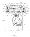
- FIG. 6is a schematic representation of a donor heart suspended in a first transport container and being perfused with oxygenated preservation solution.
- FIG. 7shows an embodiment of a hypothermic transport system of the invention, including a first transport container, a second transport container, and cooling media for maintaining the temperature of the tissue being transported.
- the first transport containercomprises a temperature sensor and a display, and the temperature can be wirelessly communicated to a second display on the exterior of the second transport container.
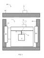
- FIG. 8shows an embodiment of a hypothermic transport system of the invention, including a first transport container, a second transport container, and recesses for holding cooling media for maintaining the temperature of the tissue being transported.
- the second transport containeris also configured to transport a source of oxygen.
- FIG. 9shows a cut-away view of a hypothermic transport system of the invention, with detail of the interior structures that provide additional mechanical protection to the first transport container and its contents.
- FIG. 10shows measurements of blood flow, renal vascular resistance, glomerular filtration rate and oxygen consumption for fresh canine kidneys ( ⁇ ), canine kidneys hypothermicaly stored for 24 hours with perfusion ( ⁇ ), and canine kidneys hypothermicly stored for 24 hours without perfusion ( ⁇ ).
- the disclosed systems for hypothermic transport of samplesprovides a sterile, temperature-stabilized environment for transporting samples while providing an ability to monitor the temperature of the samples during transport. Because of these improvements, users of the invention can reliably transport samples over much greater distances, thereby substantially increasing the pool of available tissue donations. Additionally, because the tissues are in better condition upon delivery, the long-term prognosis for the recipient is improved.
- Hypothermic transport systems of the inventioncomprise a first transport container and a second transport container.
- the first transport containerwill receive the tissue for transport, and keep it suspended or otherwise supported in a surrounding pool of preservation solution.
- the first transport containermay comprise a number of configurations suitable to transport tissues hypothermicly, provided that the first transport container includes a temperature sensor and a display.
- the first transport containercould be of a type disclosed in U.S. patent application Ser. No. 13/420,962, filed Mar. 15, 2012, and incorporated by reference herein in its entirety.
- the first transport containerwill include a pumping mechanism to circulate the preservation solution or perfuse an organ with the preservation solution.
- a first transport container comprising a pumping chamberwill be referred to as “pulsatile.” While the pumping is pulsating in preferred embodiments, the pumping is not intended to be limited to pulsating pumping, that is, the pumping may be continuous. In other embodiments, the first transport container will not circulate or perfuse the preservation solution.
- a non-pumping first transport containerwill be referred to as “static.”
- FIG. 1A general schematic of a static first transport container 1 is shown in FIG. 1 .
- the static first transport container 1includes a storage vessel 2 and a lid without a pumping chamber 6 .
- the lid without a pumping chamber 6is coupled to an adapter 26 which can be used to suspend a tissue T to be transported.
- the adapter 26can be coupled to the tissue T in any suitable manner.
- the tissue T shown in the figuresis for illustrative purposes only. That is, the invention is intended for the transport of biological samples, generally, which may include tissues, organs, body fluids, and combinations thereof.
- the static first transport container 1also includes a temperature sensor 40 which is coupled to a temperature display 45 disposed on the exterior of the static first transport container 1 . While the temperature display 45 is shown disposed on the exterior of the lid 6 , it could also be disposed on the exterior of the storage vessel 2 .
- the tissue Twill be affixed to the adapter 26 , coupled to the lid 6 , and then the lid 6 and the tissue T will be immersed into preservation solution held by storage vessel 2 .
- the lid 6will then be sealed to the storage vessel 2 using a coupling or fastener (not shown).
- the lid 6 or the storage vesselwill have entrance and exit ports (not shown) to allow a user to purge the sealed static first transport container 1 by forcing additional preservation fluid into the sealed container.
- the storage vessel 2 , lid without a pumping chamber 6 , and adapterare constructed of durable materials that are suitable for use with a medical device. Additionally, the transport container should be constructed of materials that conduct heat so that the sample within the container is adequately cooled by the cooling media (see discussion below).
- the lid 6 and storage vessel 2may be constructed of stainless steel. In other embodiments, because it is beneficial to be able to view the contents directly, the lid 6 and storage vessel may be constructed of medical acrylic (e.g., PMMA) or another clear medical polymer.
- the storage vessel 2 , lid without a pumping chamber 6 , and adapterto be sterilizable, i.e., made of a material that can be sterilized by steam (autoclave) or with UV irradiation, or another form of sterilization. Sterilization will prevent tissues from becoming infected with viruses, bacteria, etc., during transport.
- the first transport containerwill be delivered in a sterile condition and sealed in sterile packaging.
- the first transport containerwill be sterilized after use prior to reuse, for example a hospital.
- the first transport containerwill be disposable.
- the temperature sensor 40may be any temperature reading device that can be sterilized and maintained in cold fluidic environment, i.e., the environment within the static first transport container 1 during transport of tissue T.
- the temperature sensor 40may be a thermocouple, thermistor, infrared thermometer, or liquid crystal thermometer.
- Temperature display 45may be coupled to the temperature sensor 40 using any suitable method, for example a wire, cable, connector, or wirelessly using available wireless protocols.
- the temperature sensor 40may be attached to the adapter 26 .
- the temperature sensor 40is incorporated into the adapter 26 to improve the mechanical stability of the temperature sensor 40 .
- the temperature display 45can be any display suitable for displaying a temperature measured by the temperature sensor 40 , or otherwise providing information about the temperature within the static first transport container 1 .
- the temperature displaycan be a light emitting diode (LED) display or liquid crystal display (LCD) showing digits corresponding to a measured temperature.
- the displaymay alternatively comprise one or more indicator lights, for example an LED which turns on or off or flashes to indicated whether the temperature measured by the temperature sensor 40 is within an acceptable range, e.g., 2-8° C., e.g., 4-6° C., e.g., about 4° C.
- the temperature sensor 40may also be connected to a processor (not shown) which will compare the measured temperature to a threshold or range and create an alert signal when the temperature exceeds the threshold or range.
- the alertmay comprise an audible tone, or may signal to a networked device, e.g., a computer, cell phone, or pager that the temperature within the container exceeds the desired threshold or range.
- the adapter 26may be of a variety of structures suitable to suspend the tissue T in the preservation solution while minimizing the potential for mechanical damage, e.g., bruising or abrasion.
- the adapter 26is configured to be sutured to the tissue T.
- the adapter 26is coupleable to the tissue T via an intervening structure, such as silastic or other tubing.
- at least a portion of the adapter 26 , or the intervening structureis configured to be inserted into the tissue T.
- the adapter 26is configured to support the tissue T when the tissue T is coupled to the adapter.
- the adapter 26includes a retention mechanism configured to be disposed about at least a portion of the tissue T and to help retain the tissue T with respect to the adapter.
- the retention mechanismcan be, for example, a net, a cage, a sling, or the like.
- a first transport containermay additionally include a basket 8 or other support mechanism configured to support the tissue T when the tissue T is coupled to the adapter 26 or otherwise suspended in the first transport container.
- the support mechanismmay be part of an insert which fits within the first transport container, such as shown in FIG. 2 .
- the basket 8may include connectors 9 which may be flexible or hinged to allow the basket 8 to move in response to mechanical shock, thereby reducing the possibility of damage to tissue T.
- the basket 8may be coupled to the lid 6 so that it is easily immersed in and retracted from the preservation fluid held in the storage vessel 2 .
- the first transport containerwill be equipped to pump or circulate the preservation fluid.
- a pulsatile first transport container 10is shown in FIG. 3 .
- the pulsatile first transport container 10is configured to oxygenate a preservation fluid received in a pumping chamber 14 of the apparatus.
- the pulsatile first transport container 10includes a valve 12 configured to permit a fluid (e.g., oxygen) to be introduced into a first portion 16 of the pumping chamber 14 .
- a membrane 20is disposed between the first portion 16 of the pumping chamber 14 and a second portion 18 of the pumping chamber.
- the membrane 20is configured to permit the flow of a gas between the first portion 16 of the pumping chamber 14 and the second portion 18 of the pumping chamber through the membrane.
- the membrane 20is configured to substantially prevent the flow of a liquid between the second portion 18 of the pumping chamber 14 and the first portion 16 of the pumping chamber through the membrane. In this manner, the membrane can be characterized as being semi-permeable.
- the membrane 20is disposed within the pumping chamber 14 along an axis A 1 that is transverse to a horizontal axis A 2 . Said another way, the membrane 20 is inclined, for example, from a first side 22 to a second side 24 of the apparatus 10 . As such, a rising fluid in the second portion 18 of the pumping chamber 14 will be directed by the inclined membrane 20 toward a port 38 disposed at the highest portion of the pumping chamber 14 .
- the port 38is configured to permit the fluid to flow from the pumping chamber 14 into the atmosphere external to the apparatus 10 .
- the port 38is configured for unidirectional flow, and thus is configured to prevent a fluid from being introduced into the pumping chamber 14 via the port (e.g., from a source external to the pulsatile first transport container 10 ).
- the port 38includes a luer lock.
- the second portion 18 of the pumping chamber 14is configured to receive a fluid.
- the second portion 18 of the pumping chamber 14is configured to receive a preservation fluid.
- the second portion 18 of the pumping chamber 14is in fluid communication with the adapter 26 .
- the adapter 26is configured to permit movement of the fluid from the pumping chamber 14 to a tissue T.
- the pumping chamber 14defines an aperture configured to be in fluidic communication with a lumen (not shown) of the adapter 26 .
- the adapter 26is configured to be coupled to the tissue T.
- the adapter 26can be coupled to the tissue T in any suitable manner.
- the adapter 26is configured to be sutured to the tissue T.
- the adapter 26is coupleable to the tissue T via an intervening structure, such as silastic or other tubing.
- an intervening structuresuch as silastic or other tubing.
- at least a portion of the adapter 26 , or the intervening structureis configured to be inserted into the tissue T.
- the lumen of the adapter 26(or a lumen of the intervening structure) is configured to be fluidically coupled to a vessel of the tissue T.
- the tissue Tmay be suspended in a basket 8 and not connected to the adapter 26 .
- the pumping chamberserves to circulate the preservation fluid, however the tissue T is not perfused.
- the adapter 26is configured to support the tissue T when the tissue T is coupled to the adapter.
- the adapter 26includes a retention mechanism (not shown) configured to be disposed about at least a portion of the tissue T and to help retain the tissue T with respect to the adapter.
- the retention mechanismcan be, for example, a net, a cage, a sling, or the like.
- An organ chamber 30is configured to receive the tissue T and a fluid.
- the pulsatile first transport container 10includes a port 34 that is extended through the pulsatile first transport container 10 (e.g., through the pumping chamber 14 ) to the organ chamber 30 .
- the port 34is configured to permit fluid (e.g., preservation fluid) to be introduced to the organ chamber 30 .
- fluidcan be introduced into the organ chamber 30 as desired by an operator of the apparatus.
- a desired amount of preservation fluidis introduced into the organ chamber 30 via the port 34 , such as before disposing the tissue T in the organ chamber 30 and/or while the tissue T is received in the organ chamber.
- the port 34is a unidirectional port, and thus is configured to prevent the flow of fluid from the organ chamber 30 to an area external to the organ chamber through the port.
- the port 34includes a luer lock.
- the organ chamber 30may be of any suitable volume necessary for receiving the tissue T and a requisite amount of fluid for maintaining viability of the tissue T. In one embodiment, for example, the volume of the organ chamber 30 is approximately 2 liters.
- the organ chamber 30is formed by a canister 32 and a bottom portion 19 of the pumping chamber 14 .
- an upper portion of the organ chamber(defined by the bottom portion 19 of the pumping chamber 14 ) can be inclined from the first side 22 towards the second side 24 of the apparatus.
- a rising fluid in the organ chamber 30will be directed by the inclined upper portion of the organ chamber towards a valve 36 disposed at a highest portion of the organ chamber.
- the valve 36is configured to permit a fluid to flow from the organ chamber 30 to the pumping chamber 14 .
- the valve 36is configured to prevent flow of a fluid from the pumping chamber 14 to the organ chamber.
- the valve 36can be any suitable valve for permitting unidirectional flow of the fluid, including, for example, a ball check valve.
- the canister 32can be constructed of any suitable material.
- the canister 32is constructed of a material that permits an operator of the pulsatile first transport container 10 to view at least one of the tissue T or the preservation fluid received in the organ chamber 30 .
- the canister 32is substantially transparent.
- the canister 32is substantially translucent.
- the organ chamber 30can be of any suitable shape and/or size.
- the organ chamber 30can have a perimeter that is substantially oblong, oval, round, square, rectangular, cylindrical, or another suitable shape.
- a pulsatile first transport container 10also includes a temperature sensor 40 which is coupled to a temperature display 45 disposed on the exterior of the pulsatile first transport container 10 . While the temperature display 45 is shown disposed on the pumping chamber 14 , it could also be disposed on the canister 32 .
- the tissue Twill be affixed to the adapter 26 , coupled to the pumping chamber 14 , and then the pumping chamber 14 and the tissue T will be immersed into preservation solution held by organ chamber 30 .
- the temperature sensor 40may be any temperature reading device that can be sterilized and maintained in cold fluidic environment, i.e., the environment within the static first transport container 1 during transport of tissue T.
- the temperature sensor 40may be a thermocouple, thermistor, infrared thermometer, or liquid crystal thermometer.
- Temperature display 45may be coupled to the temperature sensor 40 using any suitable method, for example a wire, cable, connector, or wirelessly using available wireless protocols.
- the temperature sensor 40may be attached to the adapter 26 .
- the temperature sensor 40is incorporated into the adapter 26 to improve the mechanical stability of the temperature sensor 40 .
- the temperature display 45can be any display suitable for displaying a temperature measured by the temperature sensor 40 , or otherwise providing information about the temperature within the pulsatile first transport container 10 .
- the temperature displaycan be a light emitting diode (LED) display or liquid crystal display (LCD) showing digits corresponding to a measured temperature.
- the displaymay alternatively comprise one or more indicator lights, for example an LED which turns on or off or flashes to indicate whether the temperature of measured by the temperature sensor 40 is within an acceptable range, e.g., 2-8° C., e.g., 4-6° C., e.g., about 4° C.
- the temperature sensor 40may also be connected to a processor (not shown) which will compare the measured temperature to a threshold or range and create an alert signal when the temperature exceeds the threshold or range.
- the alertmay comprise an audible tone, or may signal to a networked device, e.g., a computer, cell phone, or pager that the temperature within the container exceeds the desired threshold or range.
- the tissue Tis coupled to the adapter 26 .
- the pumping chamber 14is coupled to the canister 32 such that the tissue T is received in the organ chamber 30 .
- the pumping chamber 14 and the canister 32are coupled such that the organ chamber 30 is hermetically sealed.
- a desired amount of preservation fluidis introduced into the organ chamber 30 via the port 34 .
- the organ chamber 30can be filled with the preservation fluid such that the preservation fluid volume rises to the highest portion of the organ chamber.
- the organ chamber 30can be filled with an additional amount of preservation fluid such that the preservation fluid flows from the organ chamber 30 through the valve 36 into the second portion 18 of the pumping chamber 14 .
- the organ chamber 30can continue to be filled with additional preservation fluid until all atmospheric gas that initially filled the second portion 18 of the pumping chamber 14 rises along the inclined membrane 20 and escapes through the port 38 . Because the gas will be expelled from the pumping chamber 14 via the port 38 before any excess preservation fluid is expelled (due to gas being lighter, and thus more easily expelled, than liquid), an operator of the pulsatile first transport container 10 can determine that substantially all excess gas has been expelled from the pumping chamber when excess preservation fluid is released via the port. As such, the pulsatile first transport container 10 can be characterized as self-purging.
- Oxygen(or another suitable fluid, e.g., dry air) is introduced into the first portion 16 of the pumping chamber 14 via the valve 12 .
- a positive pressure generated by the introduction of oxygen into the pumping chamber 14causes the oxygen to be diffused through the semi-permeable membrane 20 into the second portion 18 of the pumping chamber.
- oxygenis a gas
- the oxygenexpands to substantially fill the first portion 16 of the pumping chamber 14 .
- substantially the entire surface area of the membrane 20 between the first portion 16 and the second portion 18 of the pumping chamber 14is used to diffuse the oxygen.
- the oxygenis diffused through the membrane 20 into the preservation fluid received in the second portion 18 of the pumping chamber 14 , thereby oxygenating the preservation fluid.
- the oxygenated preservation fluidis moved from the second portion 18 of the pumping chamber 14 into the tissue T via the adapter 26 .
- the positive pressurecan cause the preservation fluid to move from the pumping chamber 14 through the lumen of the adapter 26 into the vessel of the tissue T.
- the positive pressureis also configured to help move the preservation fluid through the tissue T such that the tissue T is perfused with oxygenated preservation fluid.
- the preservation fluidis received in the organ chamber 30 .
- the preservation fluid that has been perfused through the tissue Tis combined with preservation fluid previously disposed in the organ chamber 30 .
- the volume of preservation fluid received from the tissue T following perfusion combined with the volume of preservation fluid previously disposed in the organ chamber 30exceeds a volume (e.g., a maximum fluid capacity) of the organ chamber 30 .
- a portion of the organ chamber 30is flexible and expands to accept this excess volume.
- the valve 12can then allow oxygen to vent from the first portion 16 of the pumping chamber 14 , thus, reducing the pressure in the pumping chamber 14 .
- the flexible portion of the organ chamber 30relaxes, and the excess preservation fluid is moved through the valve 36 into the pumping chamber 14 .
- the cycle of oxygenating preservation fluid and perfusing the tissue T with the oxygenated reservation fluidcan be repeated as desired.
- First transport container 700comprises a lid assembly 710 having a temperature display 745 , a canister 790 , and a coupling mechanism 850 between the lid 710 and the canister 790 .
- the first transport container 700may be hermetically sealed by actuating clamps 712 and 713 , sealing the coupling mechanism 850 , once the tissue and preservation fluid has been placed within.
- the canistermay be substantially transparent, allowing a user to view the condition of the tissue during transport.
- FIG. 5A cut-away view of first transport container capable of perfusing an organ with preservation fluid is shown in FIG. 5 . It includes a lid assembly 710 , a canister 790 , and a coupling mechanism 850 . While it is not shown in this view, the first transport container additionally comprises a temperature sensor and a display.
- the lid assembly 710defines a chamber 724 configured to receive components of a pneumatic system (not shown) and necessary control electronics.
- the chamber 724is formed by a lid 720 of the lid assembly 710 .
- the chamber 724can be formed between a lower portion 723 of the lid 720 and an upper portion 722 of the lid.
- the canister 790is configured to receive a basket 8 , such as shown in FIG. 3 .
- the lid assembly 710defines a pumping chamber 725 configured to receive oxygen to facilitate diffusion of the oxygen into a preservation fluid (not shown) and to facilitate movement of the oxygenated preservation fluid throughout the storage container.
- a top of the pumping chamber 725is formed by a lower portion 728 of a membrane frame 744 of the lid assembly 710 .
- a bottom of the pumping chamber 725is formed by an upper surface 734 of a base 732 of the lid assembly 710 .
- the lid assembly 710may include a first gasket 742 , a membrane 740 , and the membrane frame 744 .
- the membrane 740is disposed within the pumping chamber 725 and divides the pumping chamber 725 into a first portion 727 and a second portion 729 different than the first portion.
- the first gasket 742is disposed between the membrane 740 and the membrane frame 744 such that the first gasket is engaged with an upper surface 741 of the membrane 740 and a lower, perimeter portion of the membrane frame 744 .
- the first gasket 742is configured to seal a perimeter of the first portion 727 of the pumping chamber 725 twined between the lower portion 728 of the membrane frame 744 and the upper surface 741 of the membrane 740 .
- the first gasket 742is configured to substantially prevent lateral escape of oxygen from the first portion 727 of the pumping chamber 725 to a different portion of the pumping chamber.
- the first gasket 742has a perimeter substantially similar in shape to a perimeter defined by the membrane 740 (e.g., when the membrane is disposed on the membrane frame 744 ).
- a first gasketcan have another suitable shape for sealing a first portion of a pumping chamber configured to receive oxygen from a pneumatic system.
- the first gasket 742can be constructed of any suitable material.
- the first gasket 742is constructed of silicone, an elastomer, or the like.
- the first gasket 742can have any suitable thickness.
- the first gasket 742has a thickness within a range of about 0.1 inches to about 0.15 inches. More specifically, in some embodiments, the first gasket 742 has a thickness of about 0.139 inches.
- the first gasket 742can have any suitable level of compression configured to maintain the seal about the first portion 727 of the pumping chamber 725 when the components of the lid assembly 710 are assembled.
- the first gasket 742is configured to be compressed by about 20 percent.
- the membrane 740is configured to permit diffusion of gas (e.g., oxygen) from the first portion 727 of the pumping chamber 725 through the membrane to the second portion 729 of the pumping chamber, and vice versa.
- the membrane 740is configured to substantially prevent a liquid (e.g., the preservation fluid) from passing through the membrane. In this manner, the membrane 740 can be characterized as being semi-permeable.
- the membrane frame 744is configured to support the membrane 740 (e.g., during the oxygenation of the preservation fluid and perfusion of the tissue).
- the membrane frame 744can have a substantially round or circular shaped perimeter.
- the membrane frame 744includes a first port 749 A and a second port 749 B.
- the first port 749 Ais configured to convey fluid between the first portion 727 of the pumping chamber and the pneumatic system (not shown).
- the first port 749 Acan be configured to convey oxygen from the pneumatic system to the first portion 727 of the pumping chamber 725 .
- the second port 749 Bis configured to permit a pressure sensor line (not shown) to be disposed therethrough.
- the pressure sensor linecan be, for example, polyurethane tubing.
- the ports 749 A, 749 Bcan be disposed at any suitable location on the membrane frame 744 , including, for example, towards a center of the membrane frame 744 . Although the ports 749 A, 749 B are shown in close proximity, in other embodiments, the ports 749 A, 749 B can be differently spaced (e.g., closer together or further apart).
- At least a portion of the membrane 740is disposed (e.g., wrapped) about at least a portion of the membrane frame 744 .
- the membrane 740is stretched when it is disposed on the membrane frame 744 .
- the membrane 740is disposed about a lower edge or rim of the membrane frame 744 and over at least a portion of an outer perimeter of the membrane frame 744 such that the membrane 740 is engaged with a series of protrusions (e.g., protrusion 745 ) configured to help retain the membrane with respect to the membrane frame.
- the membrane frame 744is configured to be received in a recess 747 defined by the lid 720 .
- the membrane 740is engaged between the membrane frame 744 and the lid 720 , which facilitates retention of the membrane with respect to the membrane frame.
- the first gasket 742also helps to maintain the membrane 740 with respect to the membrane frame 744 because the first gasket is compressed against the membrane between the membrane frame 744 and the lid 720 .
- the membrane 740is disposed within the pumping chamber 725 at an angle with respect to a horizontal axis A 4 .
- the membrane 740is configured to facilitate movement of fluid towards a purge port 706 in fluid communication with the pumping chamber 725 , as described in more detail herein.
- the angle of incline of the membrane 740can be of any suitable value to allow fluid (e.g., gas bubbles, excess liquid) to flow towards the purge port 706 and exit the pumping chamber 725 .
- the angle of inclineis approximately in the range of 1°-10°, in the range of 2°-6°, in the range of 2.5°-5°, in the range of 4°-5° or any angle of incline in the range of 1°-10° (e.g., approximately 1°, 2°, 3°, 4°, 5°, 6°, 7°, 8°, 9°, 10°). More specifically, in some embodiments, the angle of incline is approximately 5°.
- the membrane 740can be of any suitable size and/or thickness, including, for example, a size and/or thickness described with respect to another membrane herein (e.g., membrane 140 ).
- the membrane 740can be constructed of any suitable material.
- the membraneis constructed of silicone, plastic, or another suitable material.
- the membraneis flexible.
- the membrane 740can be substantially seamless. In this manner, the membrane 740 is configured to be more resistant to being torn or otherwise damaged in the presence of a flexural stress caused by a change in pressure in the pumping chamber due to the inflow and/or release of oxygen or another gas.
- the lid 720includes the purge port 706 disposed at the highest portion of the pumping chamber 725 (e.g., at the highest portion or point of the second portion 729 of the pumping chamber 725 ).
- the purge port 706is configured to permit movement of fluid from the pumping chamber 725 to an area external to the first transport container 700 .
- the purge port 706can be similar in many respects to a purge port described herein (e.g., port 78 , purge ports 106 , 306 ).
- a desired amount of preservation fluidcan be disposed within the compartment 794 of the canister 790 prior to disposing the lid assembly 710 on the canister.
- a preservation fluid line(not shown) is connected to the storage chamber 792 and the device is flushed with preservation fluid, thereby checking for leaks and partially filling the canister 790 with preservation fluid.
- the preservation fluid linecan be disconnected.
- the lid assembly 710is disposed on the canister 790 such that the body fluids, held by holder 726 , are immersed in the storage chamber 792 .
- the lid assembly 710is coupled to the canister 790 .
- the lid assembly 710 and the canister 790are coupled via the retainer ring 850 .
- a desired amount of preservation fluidis delivered to the storage chamber 792 via the fill port 708 .
- a volume of preservation fluid greater than a volume of the storage chamber 792is delivered to the storage chamber such that the preservation fluid will move through the valves 738 A, 738 B into the second portion 729 of the pumping chamber 725 .
- oxygenmay be introduced into the first portion 727 of the pumping chamber 725 via a pneumatic system.
- the pneumatic systemis configured to generate a positive pressure by the introduction of oxygen into the first portion 727 of the pumping chamber 725 .
- the positive pressurehelps to facilitate diffusion of the oxygen through the membrane 740 .
- the oxygenis diffused through the membrane 740 into the preservation solution disposed in the second portion 729 of the pumping chamber 725 , thereby oxygenating the preservation solution. Because the oxygen will expand to fill the first portion 727 of the pumping chamber 725 , substantially all of an upper surface 741 of the membrane 740 which faces the first portion of the pumping chamber can be used to diffuse the oxygen from the first portion into the second portion 729 of the pumping chamber.
- the tissuewill release carbon dioxide into the preservation fluid.
- carbon dioxidecan be diffused from the second portion 729 of the pumping chamber 725 into the first portion 727 of the pumping chamber 725 .
- Carbon dioxide within the first portion 727 of the pumping chamberis vented via a control line (not shown) to a valve (not shown), and from the valve through a vent line (not shown) to the atmosphere external to the first transport container.
- the positive pressurealso causes the membrane 740 to flex, which transfers the positive pressure in the form of a pulse wave into the oxygenated preservation fluid.
- the pulse wave generated by the pumping chamberis configured to facilitate circulation of the oxygenated preservation fluid from the second portion 729 of the pumping chamber 725 into storage chamber 792 thereby contacting the tissue or being perfused through the tissue.
- the pulse waveis configured to flow through the preservation solution disposed in the storage chamber 792 towards the floor 793 of the canister 790 .
- the floor 793 of the canister 790is configured to flex when engaged by the pulse wave.
- the floor 793 of the canister 790is configured to return the pulse wave through the preservation fluid towards the top of the storage chamber 792 as the floor 793 of the canister 790 is returned towards its original non-flexed position.
- the returned pulse waveis configured to generate a sufficient pressure to open the valves 738 A, 738 B disposed at the highest positions in the storage chamber 792 .
- the returned pulse wavehelps to move the valves 738 A, 738 B to their respective open configurations such that excess fluid (e.g., carbon dioxide released from the body fluid and/or the preservation fluid) can move through the valves from the storage chamber 792 to the pumping chamber 725 .
- excess fluide.g., carbon dioxide released from the body fluid and/or the preservation fluid
- the foregoing cyclecan be repeated as desired, including in any manner described above with respect to other apparatus described herein.
- the preservation solutionis circulated through the tissue using the tissue's cardiovascular system.
- the tissuemay be an organ, e.g., a heart.
- the tissuecan be coupled to the pumping chamber via an adapter, which is shown in FIG. 6 as lumen 770 .
- Lumen 770may be directly attached to the organ, e.g., via the vena cava, allowing oxygenated preservation solution to be perfused through the organ.
- a temperature sensor 757may also be affixed to lumen 770 and be used to monitor the temperature of the preservation fluid in close proximity to the tissue. As shown by the arrow in FIG.
- the perfused preservation fluidwill exit the organ, e.g., via a pulmonary artery, and return to the storage chamber 792 .
- the circulation of the preservation fluid, described above,will allow the preservation solution to be re-oxygenated prior to being re-perfused into the tissue.
- perfusion pressurecan also be varied, e.g., once per second, between a low and a high pressure, thereby simulating the natural pulsatile flow of blood through the vasculature of the tissues.
- This method of perfusionprovides a more “natural” environment for absorption of oxygen and nutrients from the preservation solution, increases the amount of time that the organ can be transported, and improves the overall quality of the tissue upon arrival. Furthermore, because compressed oxygen is used to propel the pulsed circulation, the preservation fluid is reoxygenated throughout transport, replacing the oxygen that has been consumed by the tissue and displacing waste gases (i.e., CO 2 ). In some versions, a suite of sensors measures temperature, oxygen content, and pressure of the circulating fluids to assure that the tissue experiences a favorable environment during the entire transport.
- FIG. 7A complete system for hypothermic transport of tissues, comprising a static first transport container 1 and a second transport container 800 is shown in FIG. 7 .
- the first static transport containercomprises a storage vessel 2 and a lid without a pumping chamber 6 , as described above with respect to FIG. 1 .
- the second transport container 800comprises an insulated vessel 802 and an insulated lid 806 .
- the insulated vesselhas at least one recess 810 configured to hold a cooling medium 815 .
- a sealed static first transport container 1is placed in insulated vessel 802 along with cooling media 815 , and the insulated lid is placed on insulated vessel 802 forming a temperature-regulated environment for transport of tissue.
- the insulated vessel 802 and the insulated lid 806will both comprise an insulating material that is effective in maintaining the temperature inside the second transport container 800 .
- a suitable insulating materialmay be any of a number of rigid polymer foams with high R values, such as polystyrene foams (e.g. STYROFOAMTM), polyurethane foams, polyvinyl chloride foams, poly(acrylonitrile)(butadiene)(styrene) foams, or polyisocyanurate foams.
- Other materials, such as spun fiberglass, cellulose, or vermiculitecould also be used.
- the insulating vessel 802will be constructed to provide a close fit for the first transport container, thereby affording additional mechanical protection to the first transport container and the tissues contained therein.
- the insulated vessel 802 and the insulated lid 806will be constructed of a closed-cell foam that will prevent absorption of liquids, for example water, body fluids, preservation fluid, saline, etc.
- the insulated vessel 802 and the insulated lid 806may have a hard shell on the exterior to protect the insulating material from damage or puncture.
- the hard shellmay be formed of metal (e.g. aluminum or steel) or of a durable rigid plastic (e.g. PVC or ABS).
- the hard shellmay have antibacterial properties through the use of antibacterial coatings or by incorporation of metal that have innate antibacterial properties (e.g. silver or copper).
- the insulated vessel 802 and the insulated lid 806may be connected with a hinge, hasp, clasp, or other suitable connector.
- the second transport container 800may include an insulating seal to make to make an air- or water-tight coupling between the insulated vessel 802 and the insulated lid 806 .
- the insulated lid 806need not be sealed to the insulated vessel 802 for the second transport container 800 to maintain a suitable temperature during transport.
- the insulated vessel 802 and the insulated lid 806will be coupled with a combination lock or a tamper-evident device.
- the insulated vessel 802 and/or the insulated lid 806may additionally comprise a handle or a hand-hold or facilitate moving the second transport container 800 when loaded with a first transport container (static 1 or pulsatile 10 ). While not shown in FIG. 7 , in some embodiments, insulated vessel 802 will additionally have external wheels (e.g. castor wheels or in-line skate type wheels). The insulated vessel 802 may also have a rollaboard-type retractable handle to facilitate moving the system between modes of transport or around a hospital or other medical facility.
- the second transport container 800will comprise a second temperature display 46 which can display a temperature measured by the temperature sensor 40 to a user.
- the second temperature display 46may receive measurements of temperature within the static first transport container 1 via a wired or a wireless connection.
- an electronics package on the lid 6is coupled to the temperature display 45 and comprises a wireless transmitter that communicates with a receiver coupled to the second temperature display 46 .
- This configurationavoids a user having to make a connection between the temperature sensor 40 and the second temperature display 46 after the first static transport container 1 has been placed in the insulated vessel.
- the second insulated transport container 800may additionally comprise displays for additional relevant information, such as time since harvest, pressure inside the first transport container (static 1 or pulsatile 10 ), partial pressure of oxygen, or oxygen consumption rate of the biological sample.
- the systemmay use any of a number of cooling media 815 to maintain the temperature inside the second transport container 800 during transport.
- the cooling media 815may comprise eutectic cooling blocks, which have been engineered to have a stable temperature between 2-8° C., for example.
- the cooling media 815will be arranged in recess 810 in the interior of the insulated vessel 802 .
- the recess 810may be a slot 825 , such as shown in FIG. 8 , or the recess may be a press-fit, or the cooling media 815 may be coupled to the walls of the insulated vessel 802 using a snap, screw, hook and loop, or another suitable connector.
- Eutectic cooling media suitable for use with the inventionis available from TCP Reliable Inc.
- the inventionis capable of maintaining the temperature of the sample in the range of 2-8° C. for at least 60 minutes, e.g., for greater than 4 hours, for greater than 8 hours, for greater than 12 hours, or for greater than 16 hours.
- FIG. 8shows another embodiment of a complete system for hypothermic transport of tissues, comprising a first transport container ( 1 or 10 ) and a second transport container 800 .
- the second transport containercomprises an insulated vessel 802 and an insulated lid 806 .
- the insulated vesselhas recesses 810 for holding cooling media 815 .
- the insulated vesselis formed to closely fit the first transport container ( 1 or 10 ) to provide mechanical protection to the container and to assure that the container remains upright during transport.
- the insulated vessel 802 and the insulated lid 806have hard sides for durability, and may have wheels (not shown) for ease of transport. As shown in FIG.
- the insulated vessel 802additionally comprises an oxygenate recess 820 for holding a compressed oxygenate 825 , for example a cylinder of compressed oxygen.
- a compressed oxygenate 825for example a cylinder of compressed oxygen.
- the compressed oxygenatecan serve a dual purpose of oxygenating the preservation solution and also providing pressure to circulate the preservation solution around or through the tissue.
- second transport container 800may additionally comprise a regulator and tubing to connect the compressed oxygenate to the first transport container ( 1 or 10 ).
- both the insulated vessel 802 and the insulated lid 806are designed to snugly fit the first transport container ( 1 or 10 ) to provide additional mechanical stability.
- the oxygenate recess 820also provides a snug fit for the compressed oxygenate, which may be, for example, a size 4 cylinder of compressed gas.
- a thermal communication passage 850may be provided (behind wall of first transport container) to allow better thermal flow between the cooling media 815 and the first transport container ( 1 or 10 ).
- the interstitial space between the cooling media 815 and the first transport container 1 or 10will be filled with a thermal transport fluid, such as water or an aqueous solution. In other instances, the interstitial space will be filled with air or another gas (e.g. dry nitrogen).
- a thermal transport fluidsuch as water or an aqueous solution.
- the interstitial spacewill be filled with air or another gas (e.g. dry nitrogen).
- a medical professionalwill provide a hypothermic transport system of the invention, for example as shown in FIGS. 7-9 , suspend a biological sample in preservation fluid within a first transport container, for example as shown in FIGS. 1-3 , and maintain the temperature of the preservation fluid between 2 and 8° C. for at least 60 minutes.
- the first transport containerhas a temperature sensor and a temperature display, it will be possible for the medical professional to monitor the temperature of the sample after it has been sealed inside the first transport container.
- Such temperature informationwill be critical in evaluating the status of the sample during transport and for identifying failures during transport.
- having a second display on the second transport containerit will be possible to monitor the temperature of the sample without opening the second transport container, thereby maintaining the hypothermic environment within.
- the preservation fluidmay be maintained at a pressure greater than atmospheric pressure, and may be oxygenated, for example by an accompanying cylinder of compressed oxygen, i.e., as shown in FIG. 8 .
- the preservation fluidwill be circulated around tissue suspended in the first transport container, or the preservation fluid may be perfused through an organ suspended in the first transport container.
- an organwill be perfused with preservation solution by using oscillating pressures, thereby simulating the systolic and diastolic pressures experienced by circulatory system of the organ in the body.
- the body fluidsWhen body fluids are transported, the body fluids may be transported by suspending a third container (e.g., a blood bag) within the first transport container.
- a third containere.g., a blood bag
- tissue of the inventionit is possible to transport a biological sample (e.g. tissue, organs, or body fluids) over distances while maintaining a temperature of 2-8° C.
- a biological samplee.g. tissue, organs, or body fluids
- Systems of the inventionwill enable medical professionals to keep tissues (e.g. organs) in a favorable hypothermic environment for extended periods of time, thereby allowing more time between harvest and transplant.
- tissuese.g. organs
- a greater number of donor organswill be available thereby saving lives.
- the transport containeradditionally included a basket designed to support the organs.
- the organswere immersed into cold (4° C.) freshly prepared University of Wisconsin Solution (preservation solution). While the first transport container was capable of supplying pulsatile preservation solution, it was not used. That is, the kidneys were stored statically.
- the first transport containerwas then placed into an insulated transport case into which eutectic cold packs had been previously placed. Temperature was continuously monitored during 24 hours of storage. The average temperature during storage was 4.5° C.
- kidneyswere attached via aortic catheter to an adapter coupled to the lid of a first transport container.
- the aortic catheterswere attached to the adapter so that that the aorta could receive pressurized preservation solution.
- the transport containeradditionally included a basket designed to support the organs.
- the organswere then immersed into cold (4° C.) freshly prepared University of Wisconsin Solution (preservation solution).
- the first transport containerwas pressurized with 100% O 2 at 2.5 to 3.0 psi and set to perfuse the kidneys at 70 pulses/min. Temperature and perfusion pressure were continuously monitored.
- the partial pressure of oxygen (pO 2 ) in the flowing preservation solutionwas measured at 15 minute intervals, both into and out of the organ.
- the average temperature during storagewas 5.0° C.; the average perfusion pressure was 16.0 mmHg; the average preservation solution flow was 37.8 ml/min, the average O 2 delivery was 1.2 ml/min; the average O 2 consumption was 0.29 ml/min; and the average Renal Vascular Resistance (RVR; perfusion pressure ⁇ flow) was 0.43 mmHg/ml/min.
- RVRRenal Vascular Resistance
- kidneyswere removed from the preservation device and connected to a Langendorff device to evaluate kidney function.
- Four additional kidneyswere harvested and evaluated with the Langendorff device as a control.
- Each kidneywere perfused with a 50:50 mixture of warm (37° C.) oxygenated (100% O 2 ) K—H solution containing inulin (15 mg/100 ml) and autologous blood. Perfusion was initiated slowly and incremented at 5 minute intervals until a mean arterial pressure of 150 mmHg was achieved.
- Urine, arterial and venous sampleswere collected from each kidney after 90 minutes in triplicate for inulin clearance and urine output measurement. Inulin was measured using the method of Waser as modified by Brown and Nolph.
- the results of the Langendorff measurementsare shown graphically in FIG. 10 .
- the temperature during function measurements on the Langendorffwas 37.0 ⁇ 0.1° C. for all kidneys.
- Perfusion pressure for all kidneyswas set at 150 mmHg.
- Renal vascular resistance (average) for freshly recovered kidneyswas 2.8 ⁇ 0.4 mmHg/ml/min, 3.4 ⁇ 0.1 mmHg/ml/min for pulsatile stored kidneys, and 5.4 ⁇ 0.4 mmHg/ml/min for static stored kidneys.
- the RVR differences between the freshly recovered and pulsatile stored kidneyswere not statistically significant, but the statically stored kidneys demonstrated a statistically higher RVR (p ⁇ 0.05) (See FIG. 10 ).
- Oxygen consumption (average) during testing by freshly recovered kidneyswas 5.5 ⁇ 0.4 ml O 2 /min, 3.7 ⁇ 0.6 ml O 2 /min by pulsatile stored preserved kidneys, and 2.1 ⁇ 0.3 ml O 2 /min by statically stored kidneys.
- GFR (average)was 14.3 ⁇ 4.6 ml/g/min for the freshly recovered kidneys, 18.4 ⁇ 4.3 ml/min for the pulsatile preserved organs, and 7.4 ⁇ 1.8 ml/min for the statically stored organs.
- the static storage kidneysfared worse than both the fresh kidneys and the pulsatile storage kidneys in all aspects.
- the static stored kidneysshowed a significantly lower (p ⁇ 0.05) oxygen consumption and GFR than either freshly recovered or pulsatile stored preservation groups, with a marked increase in RVR (See FIG. 10 ).
Landscapes
- Life Sciences & Earth Sciences (AREA)
- Health & Medical Sciences (AREA)
- Engineering & Computer Science (AREA)
- Dentistry (AREA)
- General Health & Medical Sciences (AREA)
- Wood Science & Technology (AREA)
- Zoology (AREA)
- Environmental Sciences (AREA)
- Agricultural Chemicals And Associated Chemicals (AREA)
Abstract
Description
Claims (20)
Priority Applications (1)
| Application Number | Priority Date | Filing Date | Title |
|---|---|---|---|
| US13/572,327US9560846B2 (en) | 2012-08-10 | 2012-08-10 | System for hypothermic transport of biological samples |
Applications Claiming Priority (1)
| Application Number | Priority Date | Filing Date | Title |
|---|---|---|---|
| US13/572,327US9560846B2 (en) | 2012-08-10 | 2012-08-10 | System for hypothermic transport of biological samples |
Publications (2)
| Publication Number | Publication Date |
|---|---|
| US20140041403A1 US20140041403A1 (en) | 2014-02-13 |
| US9560846B2true US9560846B2 (en) | 2017-02-07 |
Family
ID=50065148
Family Applications (1)
| Application Number | Title | Priority Date | Filing Date |
|---|---|---|---|
| US13/572,327Active2034-05-31US9560846B2 (en) | 2012-08-10 | 2012-08-10 | System for hypothermic transport of biological samples |
Country Status (1)
| Country | Link |
|---|---|
| US (1) | US9560846B2 (en) |
Cited By (24)
| Publication number | Priority date | Publication date | Assignee | Title |
|---|---|---|---|---|
| US10201175B2 (en) | 2012-03-30 | 2019-02-12 | Givaudan Sa | N-acylated 1-aminocycloalkyl carboxylic acids as food flavouring compounds |
| US10443904B2 (en)* | 2015-10-23 | 2019-10-15 | Patrick Alan Tatom | Device for cooling substances |
| US10537127B2 (en) | 2013-10-02 | 2020-01-21 | Givaudan S.A. | Organic compounds |
| US10582715B2 (en) | 2012-03-30 | 2020-03-10 | Givaudan Sa | Powder flavour composition |
| US10645955B2 (en) | 2012-03-30 | 2020-05-12 | Givaudan Sa | N-acyl derivatives of gamma amino-butyric acid and beta alanine as food flavouring compounds |
| US10674755B2 (en) | 2013-10-02 | 2020-06-09 | Givaudan S.A. | Organic Compounds |
| US10711230B2 (en) | 2012-03-30 | 2020-07-14 | Givaudan Sa | N-acyl proline derivatives as food flavoring compounds |
| US10836712B2 (en) | 2012-03-30 | 2020-11-17 | Givaudan S.A. | Organic compounds |
| US10834951B2 (en) | 2013-10-02 | 2020-11-17 | Givaudan S.A. | Organic compounds |
| US10834943B2 (en) | 2013-10-02 | 2020-11-17 | Givaudan S.A. | Organic compounds having taste-modifying properties |
| US10834950B2 (en) | 2013-10-02 | 2020-11-17 | Givaudan S.A. | Organic compounds |
| US10856563B2 (en) | 2012-03-30 | 2020-12-08 | Givaudan S.A. | N-acyl-amino acid derivatives for improvement of the flavor profile of edible compositions |
| US10913922B2 (en) | 2012-03-30 | 2021-02-09 | Givaudan S.A. | N-acylated methionine derivatives as food flavoring compounds |
| US10975018B2 (en) | 2013-10-02 | 2021-04-13 | Givaudan Sa | Organic compounds |
| US11122826B2 (en) | 2013-10-02 | 2021-09-21 | Givaudan Sa | Organic compounds |
| US11834393B2 (en) | 2013-10-02 | 2023-12-05 | Givaudan Sa | Organic compounds having taste-modifying properties |
| USD1031028S1 (en) | 2022-09-08 | 2024-06-11 | Paragonix Technologies, Inc. | Tissue suspension adaptor |
| US12035708B2 (en) | 2011-03-15 | 2024-07-16 | Paragonix Technologies, Inc. | System for hypothermic transport of samples |
| US12070029B2 (en) | 2020-01-31 | 2024-08-27 | Paragonix Technologies, Inc. | Apparatus for tissue transport and preservation |
| US12096765B1 (en) | 2011-03-15 | 2024-09-24 | Paragonix Technologies, Inc. | System for hypothermic transport of samples |
| US12245585B2 (en) | 2019-06-11 | 2025-03-11 | Paragonix Technonogies, Inc. | Organ transport container with antiviral therapy |
| US12357533B2 (en) | 2023-08-25 | 2025-07-15 | Paragonix Technologies, Inc. | Systems and methods for maintaining organ pressure |
| USD1087382S1 (en) | 2025-01-30 | 2025-08-05 | Paragonix Technologies, Inc. | Device for transporting a biological sample |
| US12410408B2 (en) | 2024-02-02 | 2025-09-09 | Paragonix Technologies, Inc. | Method for hypothermic transport of biological samples |
Families Citing this family (13)
| Publication number | Priority date | Publication date | Assignee | Title |
|---|---|---|---|---|
| US20140260111A1 (en)* | 2013-03-15 | 2014-09-18 | Amy L. Phillips | Reusable cooler and method of selling food and beverages |
| EP3188796B1 (en)* | 2014-09-03 | 2021-12-22 | Symbiox, Inc. | Photosynthetic cellular substances |
| US20160095307A1 (en)* | 2014-10-07 | 2016-04-07 | NuTech Medical, Inc. | Method and composition for hypothermic storage of placental tissue |
| AU2016212166B2 (en)* | 2015-01-26 | 2019-10-17 | Ventana Medical Systems, Inc. | Transporter systems, assemblies and associated methods for transporting tissue samples |
| US10064273B2 (en) | 2015-10-20 | 2018-08-28 | MR Label Company | Antimicrobial copper sheet overlays and related methods for making and using |
| US11589576B2 (en) | 2016-07-01 | 2023-02-28 | Bluechiip Limited | Monitoring apparatus for temperature-controlled sample collection and transport |
| MX2022003785A (en)* | 2019-09-30 | 2022-05-20 | Basf Se | System for evaluating the insulation properties of a thermally insulated transport unit. |
| WO2023154793A2 (en)* | 2022-02-09 | 2023-08-17 | Vascular Perfusion Solutions, Inc. | Tissue perfusion system |
| EP4518651A1 (en)* | 2022-05-06 | 2025-03-12 | Paragonix Technologies, Inc. | System for hypothermic transport |
| US20230415961A1 (en)* | 2022-06-21 | 2023-12-28 | Jorge Sanchez-Olea | Event activated controls and display for a shipping container |
| CN115500347A (en)* | 2022-10-20 | 2022-12-23 | 合肥华琪生物工程有限公司 | An isolated kidney fascia suspension and fixation device |
| USD1021129S1 (en)* | 2022-10-28 | 2024-04-02 | Ruben Oganesyan | Organ chamber |
| USD1078083S1 (en)* | 2023-05-31 | 2025-06-03 | X-Therma, Inc. | Organ and tissue transport device |
Citations (137)
| Publication number | Priority date | Publication date | Assignee | Title |
|---|---|---|---|---|
| US3607646A (en) | 1968-04-04 | 1971-09-21 | Air Liquide | Method for the preservation of animal or human organs in living condition |
| US4336248A (en) | 1974-10-21 | 1982-06-22 | Biotest-Serum-Institut Gmbh | Preparation of coupled hemoglobin molecules |
| US4575498A (en) | 1983-07-21 | 1986-03-11 | Duke University | Method for restoring depleted purine nucleotide pools |
| US4952409A (en) | 1988-05-18 | 1990-08-28 | Nippon Kayaku Kabushiki Kaisha | Agent for prevention and remedy of injuries caused by ischemia |
| US5066578A (en) | 1989-12-21 | 1991-11-19 | The Regents Of The University Of California | Long-term preservation of organs for transplantation |
| US5149321A (en) | 1990-10-10 | 1992-09-22 | Klatz Ronald M | Brain resuscitation device and method for performing the same |
| USRE34387E (en) | 1983-07-21 | 1993-09-21 | Duke University | Method for restoring depleted purine nucleotide pools |
| US5252537A (en) | 1989-09-11 | 1993-10-12 | Sarl Compagnie Du Nord | Long-life cut flowers and method of treatment for obtaining such flowers |
| US5320846A (en) | 1991-04-17 | 1994-06-14 | New England Deaconess Hospital Corp. | Method and composition for testing patients with metabolic depleting diseases |
| US5326706A (en) | 1989-07-17 | 1994-07-05 | Research Foundation Of State University Of New York | Homeostatic organ preservation system |
| US5356771A (en) | 1993-03-11 | 1994-10-18 | Board Of Regents, The University Of Texas System | Combined perfusion and oxygenation organ preservation apparatus |
| US5362622A (en) | 1993-03-11 | 1994-11-08 | Board Of Regents, The University Of Texas System | Combined perfusion and oxygenation apparatus |
| US5395314A (en) | 1990-10-10 | 1995-03-07 | Life Resuscitation Technologies, Inc. | Brain resuscitation and organ preservation device and method for performing the same |
| US5434045A (en) | 1989-07-27 | 1995-07-18 | Jost Leonora I | Biological support system container |
| US5584804A (en) | 1990-10-10 | 1996-12-17 | Life Resuscitation Technologies, Inc. | Brain resuscitation and organ preservation device and method for performing the same |
| US5586438A (en)* | 1995-03-27 | 1996-12-24 | Organ, Inc. | Portable device for preserving organs by static storage or perfusion |
| US5599659A (en) | 1993-03-11 | 1997-02-04 | Breonics, Inc. | Preservation solution for ex vivo, warm preservation of tissues, explants,organs and vascular endothelial cells comprising retinal-derived fibroblast growth factor, cyclodextrin and chondroitin sulfate |
| US5601972A (en) | 1995-03-24 | 1997-02-11 | Organ, Inc. | Long term storage of red cells in unfrozen solution |
| US5629145A (en) | 1995-03-24 | 1997-05-13 | Organ, Inc. | Cryopreservation of cell suspensions |
| US5643712A (en) | 1994-05-20 | 1997-07-01 | Brasile; Lauren | Method for treating and rendering grafts nonthrombogenic and substantially nonimmunogenic using an extracellular matrix coating |
| US5656154A (en) | 1995-06-07 | 1997-08-12 | Organ, Inc. | Method and apparatus for separating a fluid into components and for washing a material |
| WO1997043899A1 (en) | 1996-05-17 | 1997-11-27 | Breonics, Inc. | Solution and process for resuscitation and reparation of ischemically damaged tissue |
| US5696152A (en) | 1996-05-07 | 1997-12-09 | Wisconsin Alumni Research Foundation | Taxol composition for use as organ preservation and cardioplegic agents |
| US5699793A (en) | 1994-05-20 | 1997-12-23 | Breonics Inc. | Diagnostic methods for monitoring functional charcteristics of an organ intended for transplantation |
| US5702881A (en) | 1993-03-16 | 1997-12-30 | Alliance Pharmaceutical Corp. | Method and solution for organ preservation comprising retinal-derived growth factor, cyclodextrin, mucopolysaccharide and fluorocarbon |
| US5707971A (en) | 1995-06-07 | 1998-01-13 | Life Resuscitation Technologies, Inc. | Modulation of glycolytic ATP production |
| US5712084A (en) | 1995-09-08 | 1998-01-27 | Research Corporation Technologies, Inc. | Donor kidney viability test for improved preservation |
| US5716378A (en) | 1996-06-06 | 1998-02-10 | Medtronic, Inc. | Heart preservation and transportation apparatus and method employing low rate cardiac pacing for improved removal of catabolites from the myocardium |
| US5827222A (en) | 1990-10-10 | 1998-10-27 | Life Resuscitation Technologies, Inc. | Method of treating at least one of brain and associated nervous tissue injury |
| US5916800A (en) | 1995-06-07 | 1999-06-29 | St. June Medical, Inc. | Cardiovascular bioreactor apparatus and method |
| US5922598A (en) | 1995-03-24 | 1999-07-13 | Organ, Inc. | Reducing tissue immunogenicity by induction of apoptosis |
| US5963335A (en) | 1997-06-25 | 1999-10-05 | Waters Instruments, Inc. | Means and method for measuring absorption of radiation-scattering samples |
| US5965433A (en) | 1996-05-29 | 1999-10-12 | Trans D.A.T.A. Service, Inc. | Portable perfusion/oxygenation module having mechanically linked dual pumps and mechanically actuated flow control for pulsatile cycling of oxygenated perfusate |
| US6014864A (en) | 1998-03-16 | 2000-01-18 | Life Science Holdings, Inc. | Cryogenic fluid heat exchanger method and apparatus |
| US6020575A (en) | 1998-04-20 | 2000-02-01 | Tcp/Reliable Inc. | Temperature-controlled container with heating means and eutectic pack |
| US6046046A (en) | 1997-09-23 | 2000-04-04 | Hassanein; Waleed H. | Compositions, methods and devices for maintaining an organ |
| WO2000018226A2 (en) | 1998-09-29 | 2000-04-06 | Organ Recovery Systems, Inc. | Apparatus and method for maintaining and/or restoring viability of organs |
| WO2000018225A1 (en) | 1998-09-29 | 2000-04-06 | Organ Recovery Systems, Inc. | Portable apparatus for storing and/or transporting biological samples, tissues and/or organs |
| US6060232A (en) | 1997-02-17 | 2000-05-09 | Fresenius Medical Care Deutschland Gmbh | Organ storage solution |
| WO2000060935A1 (en) | 1999-04-13 | 2000-10-19 | Organ Recovery Systems, Inc. | Method of cryopreservation of blood vessels by vitrification |
| DE19922310A1 (en) | 1999-05-14 | 2000-11-30 | Roger Berg | Pressure-tight vessel for conservation of tissues and organs for re- or transplantation has cooler, unit for enriching perfusion solution with oxygen and perfusion pump connected to receptacle for tissue or organ |
| WO2001037719A2 (en) | 1999-11-05 | 2001-05-31 | Breonics, Inc. | Prognostic testing of organs intended for transplantation |
| US6241945B1 (en) | 1998-03-16 | 2001-06-05 | Life Science Holdings, Inc. | Modular combined pump, filtration, oxygenation and/or debubbler apparatus |
| WO2001054495A1 (en) | 2000-01-31 | 2001-08-02 | Organ Recovery Systems, Inc. | System for organ and tissue preservation and hypothermic blood substitution |
| US6280925B1 (en) | 1999-02-11 | 2001-08-28 | Organ Recovery Systems, Inc. | Polyethylene glycol and glutathione composition and method for the treatment of blood vessels prior to cryopreservation |
| US6303388B1 (en) | 1995-03-30 | 2001-10-16 | Organ Recovery Systems, Inc. | Process for preparing novel ice-controlling molecules |
| WO2001078505A1 (en) | 2000-04-17 | 2001-10-25 | Organ Recovery Systems, Inc. | Cyclohexanediol cryoprotectant compounds |
| WO2001078504A2 (en) | 2000-04-17 | 2001-10-25 | Organ Recovery Systems, Inc. | Novel warming method of cryopreserved specimens |
| WO2001095717A2 (en) | 2000-06-09 | 2001-12-20 | Organ Recovery Systems | Cryopreservation method using cryoprotective composition of propanediol and a vehicle solution |
| USD453828S1 (en) | 2000-08-25 | 2002-02-19 | Organ Recovery Systems, Inc. | Organ perfusion apparatus |
| WO2002017714A2 (en) | 2000-08-25 | 2002-03-07 | Organ Recovery Systems, Inc. | Methods of thrombolytic organ treatment and repair |
| WO2002026034A2 (en) | 2000-08-25 | 2002-04-04 | Organ Recovery Systems Inc. | Apparatus and method for maintaining and/or restoring viability of organs |
| WO2002032225A2 (en) | 2000-10-19 | 2002-04-25 | Organ Recovery Systems | Method of cryopreservation of tissues or organs other than a blood vessel by vitrification |
| US20020064768A1 (en) | 2000-10-13 | 2002-05-30 | Pike Laboratories, Inc. | Cold storage solution for organ and biological tissue preservation |
| US6406839B1 (en) | 1993-06-04 | 2002-06-18 | Biotime, Inc. | Methods for using a plasma-like solution |
| US6475716B1 (en) | 2001-03-06 | 2002-11-05 | Biobank Co., Ltd. | Method for preserving mammalian organs |
| WO2002089571A1 (en) | 2001-05-04 | 2002-11-14 | Breonics, Inc. | Organ chamber for exsanguinous metabolic support system |
| US6485450B1 (en) | 1998-03-16 | 2002-11-26 | Life Science Holdings, Inc. | Brain resuscitation apparatus and method |
| US20020177117A1 (en) | 2000-03-13 | 2002-11-28 | Wolf E. George | Hyperbaric oxygen organ preservation system (hoops) |
| USD468436S1 (en) | 2000-08-25 | 2003-01-07 | Organ Recovery Systems, Inc. | Organ cassette |
| USD470594S1 (en) | 2000-08-25 | 2003-02-18 | Organ Recovery Systems, Inc. | Organ transporter |
| US20030053998A1 (en) | 2001-09-18 | 2003-03-20 | Daemen Marc A.R.C. | Methods and active substances for protecting organs |
| US6569615B1 (en) | 2000-04-10 | 2003-05-27 | The United States Of America As Represented By The Department Of Veteran's Affairs | Composition and methods for tissue preservation |
| US6582953B2 (en) | 1999-04-14 | 2003-06-24 | Breonics, Inc. | Organ chamber for exsanguinous metabolic support system |
| US20030125804A1 (en) | 2001-12-28 | 2003-07-03 | Kruse Steven D. | Fatigue test for prosthetic stent |
| US20030180704A1 (en) | 2002-03-19 | 2003-09-25 | Brockbank Kelvin G.M. | Ice-controlling molecules and uses thereof |
| US6642045B1 (en) | 1997-04-14 | 2003-11-04 | Breonics, Inc. | System for exsanguinous metabolic support of an organ or tissue |
| US6642019B1 (en) | 2000-11-22 | 2003-11-04 | Synthecan, Inc. | Vessel, preferably spherical or oblate spherical for growing or culturing cells, cellular aggregates, tissues and organoids and methods for using same |
| US6656380B2 (en) | 2001-10-16 | 2003-12-02 | Supachill Technologies Pty. Ltd. | Super-coolable composition having long-duration phase change capability, process for preparation of same, process for super-cooling same and articles comprising same |
| US6673008B1 (en) | 1998-04-28 | 2004-01-06 | Ronald J. Thompson | Fallopian tube and method of in vitro fertilization and embryo development |
| US6677150B2 (en) | 2001-09-14 | 2004-01-13 | Organ Transport Systems, Inc. | Organ preservation apparatus and methods |
| US20040014199A1 (en) | 2002-01-09 | 2004-01-22 | Jackson Streeter | Method for preserving organs for transplant |
| US20040038192A1 (en) | 1999-04-14 | 2004-02-26 | Breonics, Inc. | System for exsanguinous metabolic support of an organ or tissue |
| US20040038193A1 (en) | 1999-04-14 | 2004-02-26 | Breonics, Inc. | System for exsanguinous metabolic support of an organ or tissue |
| US6699231B1 (en) | 1997-12-31 | 2004-03-02 | Heartport, Inc. | Methods and apparatus for perfusion of isolated tissue structure |
| WO2004017838A2 (en) | 2002-08-23 | 2004-03-04 | Organ Recovery Systems | Connectors, particularity for transplant organs |
| US20040058432A1 (en) | 1998-09-29 | 2004-03-25 | Owen Donald R. | Apparatus and method for maintaining and/or restoring viability of organs |
| WO2004026031A2 (en) | 2002-09-18 | 2004-04-01 | Lifeblood Medical Inc. | Organ preservation and transportation apparatus and method |
| US20040067480A1 (en) | 2002-10-04 | 2004-04-08 | Organ Recovery Systems, Inc. | Method for treatment of cellular materials with sugars prior to preservation |
| WO2004052101A1 (en) | 2002-12-06 | 2004-06-24 | Organox Ab | Pest controlling composition and the use thereof |
| US6773877B2 (en) | 1995-03-30 | 2004-08-10 | Organ Recovery Systems, Inc. | Methods of using ice-controlling molecules |
| US20040171138A1 (en)* | 2002-08-14 | 2004-09-02 | Transmedics, Inc. | Heart preservation chamber |
| US20040170950A1 (en) | 2002-09-12 | 2004-09-02 | Prien Samuel D. | Organ preservation apparatus and methods |
| US6794124B2 (en) | 1995-12-15 | 2004-09-21 | Stiftelsen Facthor | Preservation solution |
| WO2004089090A1 (en) | 2003-04-12 | 2004-10-21 | Organox Ab | Vermin repellent |
| WO2004089085A2 (en) | 2003-04-04 | 2004-10-21 | Organ Recovery Systems, Inc. | Device for separating gas from a liquid path |
| US20040224299A1 (en) | 2003-04-04 | 2004-11-11 | Organ Recovery Systems | Method and apparatus for transferring heat to or from an organ or tissue container |
| US20040224298A1 (en) | 1998-09-29 | 2004-11-11 | John Brassil | Apparatus and method for determining effects of a substance of an organ |
| US20040241634A1 (en) | 2003-06-02 | 2004-12-02 | Organ Recovery Systems | Method and apparatus for pressure control for maintaining viability of organs |
| WO2005022994A1 (en) | 2003-09-03 | 2005-03-17 | Technische Universität Dresden | Extracorporeal organ conservation |
| US6905871B1 (en) | 1999-11-08 | 2005-06-14 | Universiteit Van Amsterdam | Apparatus for mechanical perfusion of donor's organ during its transport |
| US20050147958A1 (en) | 1997-09-23 | 2005-07-07 | Waleed Hassanein | Compositions, method and devices for maintaining an organ |
| US20050153271A1 (en)* | 2004-01-13 | 2005-07-14 | Wenrich Marshall S. | Organ preservation apparatus and methods |
| US20050221269A1 (en) | 2004-04-05 | 2005-10-06 | Organ Recovery Systems | Apparatus and method for perfusing an organ or tissue for isolating cells from the organ or tissue |
| US6953655B1 (en) | 1997-09-23 | 2005-10-11 | The United States Of America As Represented By The Department Of Veterans Affairs | Compositions, methods and devices for maintaining an organ |
| US20050233299A1 (en) | 2004-04-19 | 2005-10-20 | Yoshiki Sawa | Method for preserving organs for transplantation with a HGF-containing solution |
| US20050255442A1 (en) | 2004-05-14 | 2005-11-17 | Organ Recovery Systems | Apparatus and method for perfusion and determining the viability of an organ |
| US20060019388A1 (en) | 2003-02-06 | 2006-01-26 | Hutmacher Dietmar W | Bioreactor for growing cell or tissue cultures |
| US7008535B1 (en) | 2000-08-04 | 2006-03-07 | Wayne State University | Apparatus for oxygenating wastewater |
| US7029839B2 (en) | 2003-04-23 | 2006-04-18 | Human Biosystems | Methods and solutions for storing donor organs |
| WO2006042138A2 (en) | 2004-10-07 | 2006-04-20 | Transmedics, Inc. | Systems and methods for ex-vivo organ care |
| WO2006052133A2 (en) | 2004-11-12 | 2006-05-18 | Doorzand Airdrive B.V. | Composition for cold preservation and perfusion of organs |
| US20060121605A1 (en) | 2003-06-03 | 2006-06-08 | Organ Recovery Systems, Inc | Selection and propagation of progenitor cells |
| US20060121512A1 (en) | 2004-12-02 | 2006-06-08 | Organ Recovery Systems, Inc. | Biological pathways in progenitor cells |
| US20060154357A1 (en) | 2004-10-07 | 2006-07-13 | Transmedics, Inc. | Systems and methods for ex-vivo organ care |
| US20060208881A1 (en)* | 2005-03-02 | 2006-09-21 | Hitachi, Ltd. | Transportation device and method of living tissues |
| USD531320S1 (en) | 2003-04-04 | 2006-10-31 | Organ Recovery Systems | Cassette for organ transporter |
| USD531319S1 (en) | 2003-04-04 | 2006-10-31 | Organ Recovery Systems | Tube frame for organ transporter |
| US20060292544A1 (en) | 2005-06-28 | 2006-12-28 | Transmedics, Inc. | Systems, methods, compositions and solutions for perfusing an organ |
| US20070009881A1 (en) | 2003-09-03 | 2007-01-11 | Joachim Arzt | Perfusion circuit |
| DE102005048625A1 (en) | 2005-10-11 | 2007-04-12 | Universität Leipzig | System for non-cardioplegic preservation of donor hearts for transplantation, comprises an equipment for the preservation of donor hearts, coaxial aortic cannula, perfusion management, organ holding bag and perfusion solution |
| US20070166292A1 (en) | 1999-04-14 | 2007-07-19 | Breonics, Inc. | System for exsanguinous metabolic support of an organ or tissue |
| US20070184545A1 (en) | 2003-07-30 | 2007-08-09 | Plaats Arjan Van Der | Portable preservation apparatus for a donor organ |
| WO2007111495A1 (en) | 2006-03-28 | 2007-10-04 | Organ Assist B.V. | A method and a system for prolongation of the viability of a donor organ |
| US20070243518A1 (en) | 1999-06-17 | 2007-10-18 | The Regents Of The University Of California | Continuous cardiac perfusion preservation with PEG-HB for improved hypothermic storage |
| WO2007124044A2 (en) | 2006-04-19 | 2007-11-01 | Transmedics, Inc. | Systems and methods for ex vivo organ care |
| US20070275364A1 (en) | 2004-10-07 | 2007-11-29 | Waleed Hassanein | Systems and methods for ex-vivo organ care and for using lactate as an indication of donor organ status |
| US7326564B2 (en) | 2001-02-20 | 2008-02-05 | St. Jude Medical, Inc. | Flow system for medical device evaluation and production |
| JP2008120713A (en) | 2006-11-10 | 2008-05-29 | Pro:Kk | Method for preservation, resuscitation and transplantation of extracted organ |
| US20080145919A1 (en) | 2006-12-18 | 2008-06-19 | Franklin Thomas D | Portable organ and tissue preservation apparatus, kit and methods |
| US7410474B1 (en) | 1999-04-12 | 2008-08-12 | Isis Innovation Limited | Methods and means for extracorporeal organ perfusion |
| WO2008108996A1 (en) | 2007-03-01 | 2008-09-12 | Lifeline Scientific, Inc. | Perfusion regulation |
| US20080234768A1 (en) | 2007-03-20 | 2008-09-25 | Transmedics, Inc | Systems for monitoring and applying electrical currents in an organ perfusion system |
| US20080286747A1 (en) | 2007-05-18 | 2008-11-20 | Lifeline Scientific, Inc. | Ex vivo methods for validating substance testing with human organs and/or tissues |
| US20080288399A1 (en) | 2007-05-18 | 2008-11-20 | Lifeline Scientific, Inc. | Ex vivo methods for testing organ system disruption |
| CN101322861A (en) | 2007-06-13 | 2008-12-17 | 宋文彤 | Transplanted organ in vitro preservation and vigor monitoring device as well as method |
| US20080311552A1 (en) | 2005-09-20 | 2008-12-18 | London Health Sciences Centre Research, Inc. | Use of Sirnas in Organ Storage/Reperfusion Solutions |
| WO2009020412A1 (en) | 2007-07-06 | 2009-02-12 | Xenodevice Ab | System and method for organ evaluation and preservation |
| WO2009041806A1 (en) | 2007-09-28 | 2009-04-02 | Organ Assist B.V. | Organ transport container system |
| US20090197292A1 (en) | 2008-01-31 | 2009-08-06 | Transmedics, Inc | Systems and methods for ex vivo lung care |
| WO2009132018A1 (en) | 2008-04-22 | 2009-10-29 | The Board Of Regents Of The University Of Texas System | Fluidics-based pulsatile perfusion organ preservation device |
| US20100015592A1 (en) | 2005-04-22 | 2010-01-21 | Doorzand Airdrive B.V. | Device for transporting an organ |
| US20100209902A1 (en) | 2007-08-09 | 2010-08-19 | Hemarina Sa | Use of a Globin, a Globin Protomer or an Extracellular Hemoglobin for the Preservation of Organs, Tissues, Organ and Tissue Cells and Cell Cultures |
| WO2010096821A2 (en) | 2009-02-23 | 2010-08-26 | Cell & Tissue Systems, Inc. | Method for ice-free cryopreservation of tissue |
| US20100233670A1 (en) | 2006-02-13 | 2010-09-16 | Zohar Gavish | Frozen Viable Solid Organs and Method for Freezing Same |
| WO2011038251A1 (en) | 2009-09-25 | 2011-03-31 | Board Of Regents, The University Of Texas System | Fluidics based pulsatile perfusion preservation device and method |
| US20120148542A1 (en) | 2010-12-10 | 2012-06-14 | Lifeline Scientific, Inc. | Machine perfusion with complement inhibitors |
- 2012
- 2012-08-10USUS13/572,327patent/US9560846B2/enactiveActive
Patent Citations (238)
| Publication number | Priority date | Publication date | Assignee | Title |
|---|---|---|---|---|
| US3607646A (en) | 1968-04-04 | 1971-09-21 | Air Liquide | Method for the preservation of animal or human organs in living condition |
| US4336248A (en) | 1974-10-21 | 1982-06-22 | Biotest-Serum-Institut Gmbh | Preparation of coupled hemoglobin molecules |
| USRE34387E (en) | 1983-07-21 | 1993-09-21 | Duke University | Method for restoring depleted purine nucleotide pools |
| US4575498A (en) | 1983-07-21 | 1986-03-11 | Duke University | Method for restoring depleted purine nucleotide pools |
| US4952409A (en) | 1988-05-18 | 1990-08-28 | Nippon Kayaku Kabushiki Kaisha | Agent for prevention and remedy of injuries caused by ischemia |
| US5326706A (en) | 1989-07-17 | 1994-07-05 | Research Foundation Of State University Of New York | Homeostatic organ preservation system |
| US5434045A (en) | 1989-07-27 | 1995-07-18 | Jost Leonora I | Biological support system container |
| US5252537A (en) | 1989-09-11 | 1993-10-12 | Sarl Compagnie Du Nord | Long-life cut flowers and method of treatment for obtaining such flowers |
| US5066578A (en) | 1989-12-21 | 1991-11-19 | The Regents Of The University Of California | Long-term preservation of organs for transplantation |
| US5827222A (en) | 1990-10-10 | 1998-10-27 | Life Resuscitation Technologies, Inc. | Method of treating at least one of brain and associated nervous tissue injury |
| US5234405A (en) | 1990-10-10 | 1993-08-10 | Klatz Ronald M | Brain resuscitation device and method for performing the same |
| US5395314A (en) | 1990-10-10 | 1995-03-07 | Life Resuscitation Technologies, Inc. | Brain resuscitation and organ preservation device and method for performing the same |
| US5149321A (en) | 1990-10-10 | 1992-09-22 | Klatz Ronald M | Brain resuscitation device and method for performing the same |
| US5584804A (en) | 1990-10-10 | 1996-12-17 | Life Resuscitation Technologies, Inc. | Brain resuscitation and organ preservation device and method for performing the same |
| US5752929A (en) | 1990-10-10 | 1998-05-19 | Life Resuscitation Technologies, Inc. | Method of preserving organs other than the brain |
| US5709654A (en) | 1990-10-10 | 1998-01-20 | Life Resuscitation Technologies, Inc. | Apparatus for cooling living tissue |
| US5320846A (en) | 1991-04-17 | 1994-06-14 | New England Deaconess Hospital Corp. | Method and composition for testing patients with metabolic depleting diseases |
| US5356771A (en) | 1993-03-11 | 1994-10-18 | Board Of Regents, The University Of Texas System | Combined perfusion and oxygenation organ preservation apparatus |
| US5362622A (en) | 1993-03-11 | 1994-11-08 | Board Of Regents, The University Of Texas System | Combined perfusion and oxygenation apparatus |
| US5385821A (en) | 1993-03-11 | 1995-01-31 | Board Of Regents, The University Of Texas System | Method for hypothermic preservation of living tissue |
| US5599659A (en) | 1993-03-11 | 1997-02-04 | Breonics, Inc. | Preservation solution for ex vivo, warm preservation of tissues, explants,organs and vascular endothelial cells comprising retinal-derived fibroblast growth factor, cyclodextrin and chondroitin sulfate |
| US5702881A (en) | 1993-03-16 | 1997-12-30 | Alliance Pharmaceutical Corp. | Method and solution for organ preservation comprising retinal-derived growth factor, cyclodextrin, mucopolysaccharide and fluorocarbon |
| US6406839B1 (en) | 1993-06-04 | 2002-06-18 | Biotime, Inc. | Methods for using a plasma-like solution |
| US5643712A (en) | 1994-05-20 | 1997-07-01 | Brasile; Lauren | Method for treating and rendering grafts nonthrombogenic and substantially nonimmunogenic using an extracellular matrix coating |
| US5699793A (en) | 1994-05-20 | 1997-12-23 | Breonics Inc. | Diagnostic methods for monitoring functional charcteristics of an organ intended for transplantation |
| US6024698A (en) | 1994-05-20 | 2000-02-15 | Breonics, Inc. | Apparatus for monitoring functional characteristics of an organ intended for transplantations |
| US6375613B1 (en) | 1994-05-20 | 2002-04-23 | Breonics, Inc. | Prognostic testing of organs intended for transplantation |
| US5922598A (en) | 1995-03-24 | 1999-07-13 | Organ, Inc. | Reducing tissue immunogenicity by induction of apoptosis |
| US5629145A (en) | 1995-03-24 | 1997-05-13 | Organ, Inc. | Cryopreservation of cell suspensions |
| US5601972A (en) | 1995-03-24 | 1997-02-11 | Organ, Inc. | Long term storage of red cells in unfrozen solution |
| US5586438A (en)* | 1995-03-27 | 1996-12-24 | Organ, Inc. | Portable device for preserving organs by static storage or perfusion |
| US6303388B1 (en) | 1995-03-30 | 2001-10-16 | Organ Recovery Systems, Inc. | Process for preparing novel ice-controlling molecules |
| US6773877B2 (en) | 1995-03-30 | 2004-08-10 | Organ Recovery Systems, Inc. | Methods of using ice-controlling molecules |
| US5656154A (en) | 1995-06-07 | 1997-08-12 | Organ, Inc. | Method and apparatus for separating a fluid into components and for washing a material |
| US5707971A (en) | 1995-06-07 | 1998-01-13 | Life Resuscitation Technologies, Inc. | Modulation of glycolytic ATP production |
| US6174719B1 (en) | 1995-06-07 | 2001-01-16 | St. Jude Medical, Inc. | Cardiovascular bioreactor apparatus and method |
| US5916800A (en) | 1995-06-07 | 1999-06-29 | St. June Medical, Inc. | Cardiovascular bioreactor apparatus and method |
| US5712084A (en) | 1995-09-08 | 1998-01-27 | Research Corporation Technologies, Inc. | Donor kidney viability test for improved preservation |
| US6794124B2 (en) | 1995-12-15 | 2004-09-21 | Stiftelsen Facthor | Preservation solution |
| US5696152A (en) | 1996-05-07 | 1997-12-09 | Wisconsin Alumni Research Foundation | Taxol composition for use as organ preservation and cardioplegic agents |
| WO1997043899A1 (en) | 1996-05-17 | 1997-11-27 | Breonics, Inc. | Solution and process for resuscitation and reparation of ischemically damaged tissue |
| US5843024A (en) | 1996-05-17 | 1998-12-01 | Breonics, Inc. | Solution and process for resuscitation and preparation of ischemically damaged tissue |
| US5965433A (en) | 1996-05-29 | 1999-10-12 | Trans D.A.T.A. Service, Inc. | Portable perfusion/oxygenation module having mechanically linked dual pumps and mechanically actuated flow control for pulsatile cycling of oxygenated perfusate |
| US5716378A (en) | 1996-06-06 | 1998-02-10 | Medtronic, Inc. | Heart preservation and transportation apparatus and method employing low rate cardiac pacing for improved removal of catabolites from the myocardium |
| US6060232A (en) | 1997-02-17 | 2000-05-09 | Fresenius Medical Care Deutschland Gmbh | Organ storage solution |
| US6642045B1 (en) | 1997-04-14 | 2003-11-04 | Breonics, Inc. | System for exsanguinous metabolic support of an organ or tissue |
| US5963335A (en) | 1997-06-25 | 1999-10-05 | Waters Instruments, Inc. | Means and method for measuring absorption of radiation-scattering samples |
| US6046046A (en) | 1997-09-23 | 2000-04-04 | Hassanein; Waleed H. | Compositions, methods and devices for maintaining an organ |
| US20050147958A1 (en) | 1997-09-23 | 2005-07-07 | Waleed Hassanein | Compositions, method and devices for maintaining an organ |
| US6100082A (en) | 1997-09-23 | 2000-08-08 | Hassanein; Waleed H. | Perfusion apparatus and method including chemical compositions for maintaining an organ |
| US6953655B1 (en) | 1997-09-23 | 2005-10-11 | The United States Of America As Represented By The Department Of Veterans Affairs | Compositions, methods and devices for maintaining an organ |
| US6699231B1 (en) | 1997-12-31 | 2004-03-02 | Heartport, Inc. | Methods and apparatus for perfusion of isolated tissue structure |
| US6485450B1 (en) | 1998-03-16 | 2002-11-26 | Life Science Holdings, Inc. | Brain resuscitation apparatus and method |
| US6241945B1 (en) | 1998-03-16 | 2001-06-05 | Life Science Holdings, Inc. | Modular combined pump, filtration, oxygenation and/or debubbler apparatus |
| US6014864A (en) | 1998-03-16 | 2000-01-18 | Life Science Holdings, Inc. | Cryogenic fluid heat exchanger method and apparatus |
| US6020575A (en) | 1998-04-20 | 2000-02-01 | Tcp/Reliable Inc. | Temperature-controlled container with heating means and eutectic pack |
| US6673008B1 (en) | 1998-04-28 | 2004-01-06 | Ronald J. Thompson | Fallopian tube and method of in vitro fertilization and embryo development |
| WO2000018225A1 (en) | 1998-09-29 | 2000-04-06 | Organ Recovery Systems, Inc. | Portable apparatus for storing and/or transporting biological samples, tissues and/or organs |
| US20110039253A1 (en) | 1998-09-29 | 2011-02-17 | Lifeline Scientific, Inc. | Apparatus and method for maintaining and/or restoring viability of organs |
| WO2000018226A2 (en) | 1998-09-29 | 2000-04-06 | Organ Recovery Systems, Inc. | Apparatus and method for maintaining and/or restoring viability of organs |
| US8268547B2 (en) | 1998-09-29 | 2012-09-18 | Lifeline Scientific, Inc. | Method of transporting and storing a kidney |
| US8268612B2 (en) | 1998-09-29 | 2012-09-18 | Lifeline Scientific, Inc. | Apparatus and method for maintaining and/or restoring viability of organs |
| US6673594B1 (en) | 1998-09-29 | 2004-01-06 | Organ Recovery Systems | Apparatus and method for maintaining and/or restoring viability of organs |
| US20060063142A1 (en) | 1998-09-29 | 2006-03-23 | Organ Recovery Systems, Inc. | Apparatus and method for maintaining and/or restoring viability of organs |
| US20110129810A1 (en) | 1998-09-29 | 2011-06-02 | Lifeline Scientific, Inc. | Apparatus and method for maintaining and/or restoring viability of organs |
| US20110129908A1 (en) | 1998-09-29 | 2011-06-02 | Lifeline Scientific, Inc. | Apparatus and method for maintaining and/or restoring viability of organs |
| US20110059429A1 (en) | 1998-09-29 | 2011-03-10 | Lifeline Scientific, Inc. | Apparatus and method for maintaining and/or restoring viability of organs |
| US6977140B1 (en) | 1998-09-29 | 2005-12-20 | Organ Recovery Systems, Inc. | Method for maintaining and/or restoring viability of organs |
| US7749693B2 (en) | 1998-09-29 | 2010-07-06 | Lifeline Scientific, Inc. | Method of determining that an organ is not suitable for transplantation and using it for testing substances |
| US20110053256A1 (en) | 1998-09-29 | 2011-03-03 | Lifeline Scientific, Inc. | Apparatus and method for maintaining and/or restoring viability of organs |
| US20100221696A1 (en) | 1998-09-29 | 2010-09-02 | Organ Recovery Systems, Inc. | Apparatus and method for maintaining and/or restoring viability of organs |
| US7824848B2 (en) | 1998-09-29 | 2010-11-02 | Lifeline Scientific, Inc. | Apparatus and method for maintaining and/or restoring viability of organs |
| US20040224298A1 (en) | 1998-09-29 | 2004-11-11 | John Brassil | Apparatus and method for determining effects of a substance of an organ |
| US20040058432A1 (en) | 1998-09-29 | 2004-03-25 | Owen Donald R. | Apparatus and method for maintaining and/or restoring viability of organs |
| US6209343B1 (en) | 1998-09-29 | 2001-04-03 | Life Science Holdings, Inc. | Portable apparatus for storing and/or transporting biological samples, tissues and/or organs |
| US6280925B1 (en) | 1999-02-11 | 2001-08-28 | Organ Recovery Systems, Inc. | Polyethylene glycol and glutathione composition and method for the treatment of blood vessels prior to cryopreservation |
| US7410474B1 (en) | 1999-04-12 | 2008-08-12 | Isis Innovation Limited | Methods and means for extracorporeal organ perfusion |
| US6740484B1 (en) | 1999-04-13 | 2004-05-25 | Organ Recovery Systems, Inc. | Method of cryopreservation of tissues by vitrification |
| US20050100876A1 (en) | 1999-04-13 | 2005-05-12 | Organ Recovery Systems, Inc. | Method of cryopreservation of tissues by vitrification |
| WO2000060935A1 (en) | 1999-04-13 | 2000-10-19 | Organ Recovery Systems, Inc. | Method of cryopreservation of blood vessels by vitrification |
| US6194137B1 (en) | 1999-04-13 | 2001-02-27 | Organ Recovery Systems, Inc. | Method of cryopreservation of blood vessels by vitrification |
| US7157222B2 (en) | 1999-04-13 | 2007-01-02 | Organ Recovery Systems, Inc. | Method of cryopreservation of tissues by vitrification |
| US20080096184A1 (en) | 1999-04-14 | 2008-04-24 | Breonics, Inc. | System for exsanguinous metabolic support of an organ or tissue |
| US20040038193A1 (en) | 1999-04-14 | 2004-02-26 | Breonics, Inc. | System for exsanguinous metabolic support of an organ or tissue |
| US20040038192A1 (en) | 1999-04-14 | 2004-02-26 | Breonics, Inc. | System for exsanguinous metabolic support of an organ or tissue |
| US6582953B2 (en) | 1999-04-14 | 2003-06-24 | Breonics, Inc. | Organ chamber for exsanguinous metabolic support system |
| US20070166292A1 (en) | 1999-04-14 | 2007-07-19 | Breonics, Inc. | System for exsanguinous metabolic support of an organ or tissue |
| DE19922310A1 (en) | 1999-05-14 | 2000-11-30 | Roger Berg | Pressure-tight vessel for conservation of tissues and organs for re- or transplantation has cooler, unit for enriching perfusion solution with oxygen and perfusion pump connected to receptacle for tissue or organ |
| US20070243518A1 (en) | 1999-06-17 | 2007-10-18 | The Regents Of The University Of California | Continuous cardiac perfusion preservation with PEG-HB for improved hypothermic storage |
| WO2001037719A2 (en) | 1999-11-05 | 2001-05-31 | Breonics, Inc. | Prognostic testing of organs intended for transplantation |
| US6905871B1 (en) | 1999-11-08 | 2005-06-14 | Universiteit Van Amsterdam | Apparatus for mechanical perfusion of donor's organ during its transport |
| US6994954B2 (en) | 2000-01-31 | 2006-02-07 | Organ Recovery Systems, Inc. | System for organ and tissue preservation and hypothermic blood substitution |
| US20030118980A1 (en) | 2000-01-31 | 2003-06-26 | Organ Recovery Systems, Inc. | System for organ and tissue preservation and hypothermic blood substitution |
| WO2001054495A1 (en) | 2000-01-31 | 2001-08-02 | Organ Recovery Systems, Inc. | System for organ and tissue preservation and hypothermic blood substitution |
| US6492103B1 (en) | 2000-01-31 | 2002-12-10 | Organ Recovery Systems, Inc. | System for organ and tissue preservation and hypothermic blood substitution |
| US20020177117A1 (en) | 2000-03-13 | 2002-11-28 | Wolf E. George | Hyperbaric oxygen organ preservation system (hoops) |
| US6794182B2 (en) | 2000-03-13 | 2004-09-21 | E. George Wolf, Jr. | Hyperbaric oxygen organ preservation system (HOOPS) |
| US6569615B1 (en) | 2000-04-10 | 2003-05-27 | The United States Of America As Represented By The Department Of Veteran's Affairs | Composition and methods for tissue preservation |
| WO2001078505A1 (en) | 2000-04-17 | 2001-10-25 | Organ Recovery Systems, Inc. | Cyclohexanediol cryoprotectant compounds |
| US20020068360A1 (en) | 2000-04-17 | 2002-06-06 | Brockbank Kelvin G.M. | Cyclohexanediol cryoprotectant compounds |
| US6596531B2 (en) | 2000-04-17 | 2003-07-22 | Organ Recovery Systems | Two stage method for thawing cryopreserved cells |
| WO2001078504A2 (en) | 2000-04-17 | 2001-10-25 | Organ Recovery Systems, Inc. | Novel warming method of cryopreserved specimens |
| WO2001095717A2 (en) | 2000-06-09 | 2001-12-20 | Organ Recovery Systems | Cryopreservation method using cryoprotective composition of propanediol and a vehicle solution |
| US20020042131A1 (en) | 2000-06-09 | 2002-04-11 | Organ Recovery Systems | Cryopreservation method using cryoprotective composition of propanediol and a vehicle solution |
| US7008535B1 (en) | 2000-08-04 | 2006-03-07 | Wayne State University | Apparatus for oxygenating wastewater |
| US7294278B2 (en) | 2000-08-04 | 2007-11-13 | Wayne State University | Method for oxygenating wastewater |
| USD453828S1 (en) | 2000-08-25 | 2002-02-19 | Organ Recovery Systems, Inc. | Organ perfusion apparatus |
| US20020051779A1 (en) | 2000-08-25 | 2002-05-02 | Organ Recovery Systems, Inc. | Methods of thrombolytic organ treatment and repair |
| WO2002017714A2 (en) | 2000-08-25 | 2002-03-07 | Organ Recovery Systems, Inc. | Methods of thrombolytic organ treatment and repair |
| WO2002026034A2 (en) | 2000-08-25 | 2002-04-04 | Organ Recovery Systems Inc. | Apparatus and method for maintaining and/or restoring viability of organs |
| US20110183310A1 (en) | 2000-08-25 | 2011-07-28 | Lifeline Scientific, Inc. | Apparatus and method for maintaining and/or restoring viability of organs |
| USD470594S1 (en) | 2000-08-25 | 2003-02-18 | Organ Recovery Systems, Inc. | Organ transporter |
| USD468436S1 (en) | 2000-08-25 | 2003-01-07 | Organ Recovery Systems, Inc. | Organ cassette |
| US20020064768A1 (en) | 2000-10-13 | 2002-05-30 | Pike Laboratories, Inc. | Cold storage solution for organ and biological tissue preservation |
| US20020115634A1 (en) | 2000-10-13 | 2002-08-22 | Pike Laboratories, Inc. | Organ and biological tissue preservation cold storage solution |
| US7005253B2 (en) | 2000-10-13 | 2006-02-28 | Ben O'Mar Arrington | Cold storage solution for organ and biological tissue preservation |
| WO2002032225A2 (en) | 2000-10-19 | 2002-04-25 | Organ Recovery Systems | Method of cryopreservation of tissues or organs other than a blood vessel by vitrification |
| US6642019B1 (en) | 2000-11-22 | 2003-11-04 | Synthecan, Inc. | Vessel, preferably spherical or oblate spherical for growing or culturing cells, cellular aggregates, tissues and organoids and methods for using same |
| US7326564B2 (en) | 2001-02-20 | 2008-02-05 | St. Jude Medical, Inc. | Flow system for medical device evaluation and production |
| US6475716B1 (en) | 2001-03-06 | 2002-11-05 | Biobank Co., Ltd. | Method for preserving mammalian organs |
| US20030022148A1 (en) | 2001-03-06 | 2003-01-30 | Biobank Co., Ltd. | Method for preserving mammalian organs |
| WO2002089571A1 (en) | 2001-05-04 | 2002-11-14 | Breonics, Inc. | Organ chamber for exsanguinous metabolic support system |
| US6677150B2 (en) | 2001-09-14 | 2004-01-13 | Organ Transport Systems, Inc. | Organ preservation apparatus and methods |
| US7176015B2 (en) | 2001-09-14 | 2007-02-13 | Organ Transport Systems, Inc. | Organ preservation apparatus and methods |
| US6924267B2 (en) | 2001-09-18 | 2005-08-02 | Suomen Punainen Risti Veripalvelu | Methods and active substances for protecting organs |
| US20030053998A1 (en) | 2001-09-18 | 2003-03-20 | Daemen Marc A.R.C. | Methods and active substances for protecting organs |
| US20050277106A1 (en) | 2001-09-18 | 2005-12-15 | Suomen Punainen Risti Veripalvelu | Methods and active substances for protecting organs |
| US6656380B2 (en) | 2001-10-16 | 2003-12-02 | Supachill Technologies Pty. Ltd. | Super-coolable composition having long-duration phase change capability, process for preparation of same, process for super-cooling same and articles comprising same |
| US20030125804A1 (en) | 2001-12-28 | 2003-07-03 | Kruse Steven D. | Fatigue test for prosthetic stent |
| US20040014199A1 (en) | 2002-01-09 | 2004-01-22 | Jackson Streeter | Method for preserving organs for transplant |
| US20080070229A1 (en) | 2002-01-09 | 2008-03-20 | Jackson Streeter | Method for preserving organs for transplantation |
| US7316922B2 (en) | 2002-01-09 | 2008-01-08 | Photothera Inc. | Method for preserving organs for transplant |
| US20030180704A1 (en) | 2002-03-19 | 2003-09-25 | Brockbank Kelvin G.M. | Ice-controlling molecules and uses thereof |
| US7572622B2 (en) | 2002-08-14 | 2009-08-11 | Transmedic, Inc. | Heart preservation chamber |
| US20040171138A1 (en)* | 2002-08-14 | 2004-09-02 | Transmedics, Inc. | Heart preservation chamber |
| US20040111104A1 (en) | 2002-08-23 | 2004-06-10 | Organ Recovery Systems | Cannulas, cannula mount assemblies, and clamping methods using such cannulas and cannula mount assemblies |
| WO2004017838A2 (en) | 2002-08-23 | 2004-03-04 | Organ Recovery Systems | Connectors, particularity for transplant organs |
| US20040170950A1 (en) | 2002-09-12 | 2004-09-02 | Prien Samuel D. | Organ preservation apparatus and methods |
| WO2004026031A2 (en) | 2002-09-18 | 2004-04-01 | Lifeblood Medical Inc. | Organ preservation and transportation apparatus and method |
| US20060121439A1 (en) | 2002-09-18 | 2006-06-08 | Jan Baker | Organ preservation and transportation apparatus and method |
| US20080070302A1 (en) | 2002-10-04 | 2008-03-20 | Organ Recovery Systems, Inc. | Method for treatment of cellular materials with sugars prior to preservation |
| US7270946B2 (en) | 2002-10-04 | 2007-09-18 | Organ Recovery Systems, Inc. | Method for treatment of cellular materials with sugars prior to preservation |
| US20040067480A1 (en) | 2002-10-04 | 2004-04-08 | Organ Recovery Systems, Inc. | Method for treatment of cellular materials with sugars prior to preservation |
| WO2004052101A1 (en) | 2002-12-06 | 2004-06-24 | Organox Ab | Pest controlling composition and the use thereof |
| US20060141077A1 (en) | 2002-12-06 | 2006-06-29 | Organox Ab | Pest controlling composition and the use thereof |
| US20060019388A1 (en) | 2003-02-06 | 2006-01-26 | Hutmacher Dietmar W | Bioreactor for growing cell or tissue cultures |
| US7691622B2 (en) | 2003-04-04 | 2010-04-06 | Lifeline Scientific, Inc. | Method and apparatus for transferring heat to or from an organ or tissue container |
| US20040248281A1 (en) | 2003-04-04 | 2004-12-09 | Organ Recovery Systems, Inc. | Method and apparatus for controlling air pressure in an organ or tissue container |
| US7678563B2 (en)* | 2003-04-04 | 2010-03-16 | Organ Recovery Systems, Inc. | Method and apparatus for controlling air pressure in an organ or tissue container |
| USD531320S1 (en) | 2003-04-04 | 2006-10-31 | Organ Recovery Systems | Cassette for organ transporter |
| USD531319S1 (en) | 2003-04-04 | 2006-10-31 | Organ Recovery Systems | Tube frame for organ transporter |
| US20100112542A1 (en) | 2003-04-04 | 2010-05-06 | Organ Recovery Systems, Inc. | Method and apparatus for controlling air pressure in an organ or tissue container |
| US8097449B2 (en) | 2003-04-04 | 2012-01-17 | Organ Recovery Systems | Method and apparatus for transferring heat to or from an organ or tissue container |
| US20040221719A1 (en) | 2003-04-04 | 2004-11-11 | Organ Recovery Systems, Inc. | Device for separating gas from a liquid path |
| US20100151559A1 (en) | 2003-04-04 | 2010-06-17 | Lifeline Scientific, Inc. | Method and apparatus for transferring heat to or from an organ or tissue container |
| US20040224299A1 (en) | 2003-04-04 | 2004-11-11 | Organ Recovery Systems | Method and apparatus for transferring heat to or from an organ or tissue container |
| WO2004089085A2 (en) | 2003-04-04 | 2004-10-21 | Organ Recovery Systems, Inc. | Device for separating gas from a liquid path |
| US7361365B2 (en) | 2003-04-12 | 2008-04-22 | Organox Ab | Vermin repellent |
| WO2004089090A1 (en) | 2003-04-12 | 2004-10-21 | Organox Ab | Vermin repellent |
| US7029839B2 (en) | 2003-04-23 | 2006-04-18 | Human Biosystems | Methods and solutions for storing donor organs |
| WO2004105484A1 (en) | 2003-05-22 | 2004-12-09 | Breonics, Inc. | System for exsanguinous metabolic support of an organ or tissue |
| US20040241634A1 (en) | 2003-06-02 | 2004-12-02 | Organ Recovery Systems | Method and apparatus for pressure control for maintaining viability of organs |
| US7897327B2 (en) | 2003-06-02 | 2011-03-01 | Organ Recovery Systems, Inc. | Method and apparatus for pressure control for maintaining viability of organs |
| WO2004110146A1 (en) | 2003-06-02 | 2004-12-23 | Organ Recovery Systems, Inc. | Method and apparatus for pressure control for maintaining viability of organs |
| US20060121605A1 (en) | 2003-06-03 | 2006-06-08 | Organ Recovery Systems, Inc | Selection and propagation of progenitor cells |
| US20070184545A1 (en) | 2003-07-30 | 2007-08-09 | Plaats Arjan Van Der | Portable preservation apparatus for a donor organ |
| US7811808B2 (en) | 2003-07-30 | 2010-10-12 | Organ Assist B.V. | Portable preservation apparatus for a donor organ |
| WO2005022994A1 (en) | 2003-09-03 | 2005-03-17 | Technische Universität Dresden | Extracorporeal organ conservation |
| US20070015131A1 (en) | 2003-09-03 | 2007-01-18 | Joachim Arzt | Extracorporeal organ conservation |
| US20070009881A1 (en) | 2003-09-03 | 2007-01-11 | Joachim Arzt | Perfusion circuit |
| US20050153271A1 (en)* | 2004-01-13 | 2005-07-14 | Wenrich Marshall S. | Organ preservation apparatus and methods |
| US20090291486A1 (en) | 2004-01-13 | 2009-11-26 | Organ Transport Systems, Inc. | Organ preservation apparatus and methods |
| WO2005074681A2 (en) | 2004-02-02 | 2005-08-18 | Organ Recovery Systems, Inc. | Apparatus and method for determining effects of a substance on an organ |
| US7504201B2 (en) | 2004-04-05 | 2009-03-17 | Organ Recovery Systems | Method for perfusing an organ and for isolating cells from the organ |
| US20090226878A1 (en) | 2004-04-05 | 2009-09-10 | Organ Recovery Systems | Apparatus and method for perfusing an organ or tissue for isolating cells from the organ or tissue |
| WO2005099588A2 (en) | 2004-04-05 | 2005-10-27 | Organ Recovery Systems, Inc. | Apparatus and method for perfusing an organ or tissue for isolating cells from the organ or tissue |
| US20050221269A1 (en) | 2004-04-05 | 2005-10-06 | Organ Recovery Systems | Apparatus and method for perfusing an organ or tissue for isolating cells from the organ or tissue |
| US20050233299A1 (en) | 2004-04-19 | 2005-10-20 | Yoshiki Sawa | Method for preserving organs for transplantation with a HGF-containing solution |
| US20050255442A1 (en) | 2004-05-14 | 2005-11-17 | Organ Recovery Systems | Apparatus and method for perfusion and determining the viability of an organ |
| WO2006033674A1 (en) | 2004-05-14 | 2006-03-30 | Organ Recovery Systems, Inc. | Apparatus and method for perfusion and determining the viability of an organ |
| US20070190636A1 (en) | 2004-10-07 | 2007-08-16 | Transmedics, Inc. | Systems and methods for ex-vivo organ care |
| US20060154359A1 (en) | 2004-10-07 | 2006-07-13 | Transmedics, Inc. | Systems and methods for ex-vivo organ care |
| US20060160204A1 (en) | 2004-10-07 | 2006-07-20 | Transmedics, Inc. | Systems and methods for ex-vivo organ care |
| US8465970B2 (en) | 2004-10-07 | 2013-06-18 | Transmedics, Inc. | Systems and methods for ex-vivo organ care |
| US7651835B2 (en) | 2004-10-07 | 2010-01-26 | Transmedics, Inc. | Method of timing pulsatile flow of normothermic perfusate to the heart |
| WO2006042138A2 (en) | 2004-10-07 | 2006-04-20 | Transmedics, Inc. | Systems and methods for ex-vivo organ care |
| US20070275364A1 (en) | 2004-10-07 | 2007-11-29 | Waleed Hassanein | Systems and methods for ex-vivo organ care and for using lactate as an indication of donor organ status |
| US8304181B2 (en)* | 2004-10-07 | 2012-11-06 | Transmedics, Inc. | Method for ex-vivo organ care and for using lactate as an indication of donor organ status |
| US20060148062A1 (en) | 2004-10-07 | 2006-07-06 | Transmedics, Inc. | Systems and methods for ex-vivo organ care |
| US20060154358A1 (en) | 2004-10-07 | 2006-07-13 | Transmedics, Inc. | Systems and methods for ex-vivo organ care |
| US20060154357A1 (en) | 2004-10-07 | 2006-07-13 | Transmedics, Inc. | Systems and methods for ex-vivo organ care |
| WO2006052133A2 (en) | 2004-11-12 | 2006-05-18 | Doorzand Airdrive B.V. | Composition for cold preservation and perfusion of organs |
| US20080187901A1 (en) | 2004-11-12 | 2008-08-07 | Doorzand Airdrive B.V. | Composition For Cold Preservation and Perfusion of Organs |
| WO2006060709A2 (en) | 2004-12-02 | 2006-06-08 | Organ Recovery Systems, Inc. | Biological pathways in progenitor cells |
| US20060121512A1 (en) | 2004-12-02 | 2006-06-08 | Organ Recovery Systems, Inc. | Biological pathways in progenitor cells |
| US20060208881A1 (en)* | 2005-03-02 | 2006-09-21 | Hitachi, Ltd. | Transportation device and method of living tissues |
| US20100015592A1 (en) | 2005-04-22 | 2010-01-21 | Doorzand Airdrive B.V. | Device for transporting an organ |
| US20060292544A1 (en) | 2005-06-28 | 2006-12-28 | Transmedics, Inc. | Systems, methods, compositions and solutions for perfusing an organ |
| US20080311552A1 (en) | 2005-09-20 | 2008-12-18 | London Health Sciences Centre Research, Inc. | Use of Sirnas in Organ Storage/Reperfusion Solutions |
| DE102005048625A1 (en) | 2005-10-11 | 2007-04-12 | Universität Leipzig | System for non-cardioplegic preservation of donor hearts for transplantation, comprises an equipment for the preservation of donor hearts, coaxial aortic cannula, perfusion management, organ holding bag and perfusion solution |
| US20100233670A1 (en) | 2006-02-13 | 2010-09-16 | Zohar Gavish | Frozen Viable Solid Organs and Method for Freezing Same |
| US20100234928A1 (en) | 2006-03-28 | 2010-09-16 | Organ Assist B.V. | Method and a system for prolongation of the viability of a donor organ |
| WO2007111495A1 (en) | 2006-03-28 | 2007-10-04 | Organ Assist B.V. | A method and a system for prolongation of the viability of a donor organ |
| US20080017194A1 (en) | 2006-04-19 | 2008-01-24 | Transmedics, Inc | Systems and methods for ex vivo organ care |
| WO2007124044A2 (en) | 2006-04-19 | 2007-11-01 | Transmedics, Inc. | Systems and methods for ex vivo organ care |
| US20110136096A1 (en) | 2006-04-19 | 2011-06-09 | Transmedics, Inc. | Systems and Methods for Ex Vivo Organ Care |
| JP2008120713A (en) | 2006-11-10 | 2008-05-29 | Pro:Kk | Method for preservation, resuscitation and transplantation of extracted organ |
| US20080145919A1 (en) | 2006-12-18 | 2008-06-19 | Franklin Thomas D | Portable organ and tissue preservation apparatus, kit and methods |
| US20100028850A1 (en) | 2007-03-01 | 2010-02-04 | Lifeline Scientific, Inc. | Perfusion regulation |
| WO2008108996A1 (en) | 2007-03-01 | 2008-09-12 | Lifeline Scientific, Inc. | Perfusion regulation |
| US20080234768A1 (en) | 2007-03-20 | 2008-09-25 | Transmedics, Inc | Systems for monitoring and applying electrical currents in an organ perfusion system |
| WO2008150587A2 (en) | 2007-04-25 | 2008-12-11 | Transmedics, Inc. | Systems and methods for ex-vivo organ care using lactate as an indicator |
| WO2008144021A2 (en) | 2007-05-18 | 2008-11-27 | Lifeline Scientific, Inc. | Ex vivo methods for validating substance testing with human organs and/or tissues |
| US20080288399A1 (en) | 2007-05-18 | 2008-11-20 | Lifeline Scientific, Inc. | Ex vivo methods for testing organ system disruption |
| US20080286747A1 (en) | 2007-05-18 | 2008-11-20 | Lifeline Scientific, Inc. | Ex vivo methods for validating substance testing with human organs and/or tissues |
| CN101322861A (en) | 2007-06-13 | 2008-12-17 | 宋文彤 | Transplanted organ in vitro preservation and vigor monitoring device as well as method |
| WO2009020412A1 (en) | 2007-07-06 | 2009-02-12 | Xenodevice Ab | System and method for organ evaluation and preservation |
| US20100209902A1 (en) | 2007-08-09 | 2010-08-19 | Hemarina Sa | Use of a Globin, a Globin Protomer or an Extracellular Hemoglobin for the Preservation of Organs, Tissues, Organ and Tissue Cells and Cell Cultures |
| WO2009041806A1 (en) | 2007-09-28 | 2009-04-02 | Organ Assist B.V. | Organ transport container system |
| US20110033916A1 (en) | 2007-09-28 | 2011-02-10 | Organ Assist B.V. | Organ transport container system |
| US20090197241A1 (en) | 2008-01-31 | 2009-08-06 | Transmedics, Inc | Systems and methods for ex vivo lung care |
| US20090197292A1 (en) | 2008-01-31 | 2009-08-06 | Transmedics, Inc | Systems and methods for ex vivo lung care |
| US20090197325A1 (en) | 2008-01-31 | 2009-08-06 | Transmedics, Inc | SYSTEMS AND METHODS FOR Ex vivo LUNG CARE |
| US8420380B2 (en) | 2008-01-31 | 2013-04-16 | Transmedics, Inc. | Systems and methods for ex vivo lung care |
| US20090197240A1 (en) | 2008-01-31 | 2009-08-06 | Transmedics, Inc | Systems and methods for ex vivo lung care |
| US20090197324A1 (en) | 2008-01-31 | 2009-08-06 | Robert Fishman | Systems and methods for ex vivo lung care |
| WO2009099939A2 (en) | 2008-01-31 | 2009-08-13 | Transmedics, Inc. | Systems and methods for ex vivo lung care |
| CA2722615A1 (en) | 2008-04-22 | 2009-10-29 | The Board Of Regents Of The University Of Texas System | Fluidics-based pulsatile perfusion organ preservation device |
| EP2278874A1 (en) | 2008-04-22 | 2011-02-02 | The Board of Regents of The University of Texas System | Fluidics-based pulsatile perfusion organ preservation device |
| US20100086907A1 (en)* | 2008-04-22 | 2010-04-08 | Leonid Bunegin | Fluidics based pulsatile perfusion preservation device and method |
| US20110217689A1 (en) | 2008-04-22 | 2011-09-08 | Board Of Regents, The University Of Texas Systems | Fluidics based pulsatile perfusion preservation device and method |
| WO2009132018A1 (en) | 2008-04-22 | 2009-10-29 | The Board Of Regents Of The University Of Texas System | Fluidics-based pulsatile perfusion organ preservation device |
| WO2010096821A2 (en) | 2009-02-23 | 2010-08-26 | Cell & Tissue Systems, Inc. | Method for ice-free cryopreservation of tissue |
| US20100216110A1 (en) | 2009-02-23 | 2010-08-26 | Cell & Tissue Systems, Inc. | Method for ice-free cryopreservation of tissue |
| EP2480069A1 (en) | 2009-09-25 | 2012-08-01 | Board of Regents, The University of Texas System | Fluidics based pulsatile perfusion preservation device and method |
| US20110212431A1 (en) | 2009-09-25 | 2011-09-01 | Leonid Bunegin | Fluidics based pulsatile perfusion preservation device and method |
| WO2011038251A1 (en) | 2009-09-25 | 2011-03-31 | Board Of Regents, The University Of Texas System | Fluidics based pulsatile perfusion preservation device and method |
| US20120148542A1 (en) | 2010-12-10 | 2012-06-14 | Lifeline Scientific, Inc. | Machine perfusion with complement inhibitors |
Non-Patent Citations (20)
| Title |
|---|
| Bunegin, et al., Interstitial pO2 and High Energy Phosphates in the Canine Heart during Hypothermic Preservation in a New, Portable, Pulsatile Perfusion Device, from the Department of Anesthesiology University of Texas Health Science Center at San Antonio, Texas; and Center for Cardiovascular Surgery of the Republic of Lithuania, Vilnius, Lithuania, vol. 3, No. 3, Oct. 1998, pp. 1-6. |
| Bunegin, et al., The Application of Fluidics Based Technology for Perfusion Preservation of Adult, Human Sized, Canine Hearts, from the Department of Anesthesiology, Health Science Center at San Antonio, University of Texas, vol. 8, No. 1/2 (2003), pp. 73-78. |
| Bunegin, et al., The Application of Fluidics Technology for Organ Preservation, Biomedical Instrumentation & Technology, Mar./Apr. 2004, pp. 155-164. |
| Calhoon, et al., Twelve-Hour Canine Heart Preservation With a Simple, Portable Hypothermic Organ Perfusion Device, Ann Thorac Surg 1996;62:91-3. |
| http://organtransportsystems.com/index.html. |
| http://www.organ-recovery.com/home.php. |
| International Preliminary Report on Patentability for PCT Application No. PCT/US2009/041274. |
| LifePort Brochure, Organ Recovery Systems, www.organ-recovery.com. |
| Search Report and Written Opinion for PCT Application No. PCT/US2010/050230. |
| Search Report for PCT Application No. PCT/US2009/041274. |
| Steinbrook, The New England Journal of Medicine, Organ Donation after Cardiac Death, Jul. 19, 2007. |
| Tolstykh, et al., Novel portable hypothermic pulsatile perfusion preservation technology: Improved viability and function of rodent and canine kidneys, Ann Transplant, 2010; 15(3):1-9. |
| Tolstykh, et al., Perfusion Preservation of Rodent Kidneys in a Portable Preservation Device Based on Fluidics Technology, vol. 73, 1508-1526, No. 9, May 15, 2002. |
| U.S. Appl. No. 13/420,962, filed Mar. 15, 2012, Apparatus for Oxygenation and Perfusion of Tissue for Organ Preservation, Maier and Judson. |
| U.S. Appl. No. 13/572,315, filed Aug. 10, 2012, System for Hypothermic Transport of Samples, Anderson (née Maier) and Judson. |
| U.S. Appl. No. 13/572,323, filed Aug. 10, 2012, Methods and Devices for Preserving Tissues, Anderson (née Maier) and Judson. |
| U.S. Appl. No. 13/572,332, filed Aug. 10, 2012, Methods and Systems for Assessing Ex-Vivo Organ Health, Anderson (née Maier) and Judson. |
| U.S. Appl. No. 13/572,341, filed Aug. 10, 2012, Storage and Preservation of Body Fluids, Anderson (née Maier), Judson, and Edelman. |
| Wandall, et al., Galactosylation does not prevent the rapid clearance of long-term 40C-stored platelets, Blood, 2008; 111(6):3249-3256. |
| Weegman, et al., Continuous Real-time Viability Assessment of Kidneys Based on Oxygen Consumption, Transplant Proc. 2010; 42(6): 2020-2023. |
Cited By (37)
| Publication number | Priority date | Publication date | Assignee | Title |
|---|---|---|---|---|
| US12245586B2 (en) | 2011-03-15 | 2025-03-11 | Paragonix Technologies, Inc. | System for hypothermic transport of samples |
| US12369576B2 (en) | 2011-03-15 | 2025-07-29 | Paragonix Technologies, Inc. | System for hypothermic transport of samples |
| US12342810B2 (en) | 2011-03-15 | 2025-07-01 | Paragonix Technologies, Inc. | System for hypothermic transport of samples |
| US12035708B2 (en) | 2011-03-15 | 2024-07-16 | Paragonix Technologies, Inc. | System for hypothermic transport of samples |
| US12052985B2 (en) | 2011-03-15 | 2024-08-06 | Paragonix Technologies, Inc. | System for hypothermic transport of samples |
| US12279610B2 (en) | 2011-03-15 | 2025-04-22 | Paragonix Technonogies, Inc. | System for hypothermic transport of samples |
| US12096765B1 (en) | 2011-03-15 | 2024-09-24 | Paragonix Technologies, Inc. | System for hypothermic transport of samples |
| US12121023B1 (en) | 2011-03-15 | 2024-10-22 | Paragonix Technologies, Inc. | System for hypothermic transport of samples |
| US10645955B2 (en) | 2012-03-30 | 2020-05-12 | Givaudan Sa | N-acyl derivatives of gamma amino-butyric acid and beta alanine as food flavouring compounds |
| US10836712B2 (en) | 2012-03-30 | 2020-11-17 | Givaudan S.A. | Organic compounds |
| US10711230B2 (en) | 2012-03-30 | 2020-07-14 | Givaudan Sa | N-acyl proline derivatives as food flavoring compounds |
| US10856563B2 (en) | 2012-03-30 | 2020-12-08 | Givaudan S.A. | N-acyl-amino acid derivatives for improvement of the flavor profile of edible compositions |
| US10913922B2 (en) | 2012-03-30 | 2021-02-09 | Givaudan S.A. | N-acylated methionine derivatives as food flavoring compounds |
| US11832638B2 (en) | 2012-03-30 | 2023-12-05 | Givaudan Sa | N-acyl derivatives of gamma amino-butyric acid and beta alanine as food flavouring compounds |
| US11091429B2 (en) | 2012-03-30 | 2021-08-17 | Givaudan Sa | Organic compounds |
| US10582715B2 (en) | 2012-03-30 | 2020-03-10 | Givaudan Sa | Powder flavour composition |
| US11492326B2 (en) | 2012-03-30 | 2022-11-08 | Givaudan Sa | Organic compounds |
| US11524933B2 (en) | 2012-03-30 | 2022-12-13 | Givaudan Sa | In or relating to organic compounds |
| US10201175B2 (en) | 2012-03-30 | 2019-02-12 | Givaudan Sa | N-acylated 1-aminocycloalkyl carboxylic acids as food flavouring compounds |
| US11834393B2 (en) | 2013-10-02 | 2023-12-05 | Givaudan Sa | Organic compounds having taste-modifying properties |
| US10834951B2 (en) | 2013-10-02 | 2020-11-17 | Givaudan S.A. | Organic compounds |
| US11122826B2 (en) | 2013-10-02 | 2021-09-21 | Givaudan Sa | Organic compounds |
| US10975018B2 (en) | 2013-10-02 | 2021-04-13 | Givaudan Sa | Organic compounds |
| US10537127B2 (en) | 2013-10-02 | 2020-01-21 | Givaudan S.A. | Organic compounds |
| US10834950B2 (en) | 2013-10-02 | 2020-11-17 | Givaudan S.A. | Organic compounds |
| US10834943B2 (en) | 2013-10-02 | 2020-11-17 | Givaudan S.A. | Organic compounds having taste-modifying properties |
| US10674755B2 (en) | 2013-10-02 | 2020-06-09 | Givaudan S.A. | Organic Compounds |
| US10443904B2 (en)* | 2015-10-23 | 2019-10-15 | Patrick Alan Tatom | Device for cooling substances |
| US12245585B2 (en) | 2019-06-11 | 2025-03-11 | Paragonix Technonogies, Inc. | Organ transport container with antiviral therapy |
| US12178206B2 (en) | 2020-01-31 | 2024-12-31 | Paragonix Technologies, Inc. | Apparatus for tissue transport and preservation |
| US12161110B2 (en) | 2020-01-31 | 2024-12-10 | Paragonix Technologies, Inc. | Apparatus for tissue transport and preservation |
| US12310357B2 (en) | 2020-01-31 | 2025-05-27 | Paragonix Technologies, Inc. | Apparatus for tissue transport and preservation |
| US12070029B2 (en) | 2020-01-31 | 2024-08-27 | Paragonix Technologies, Inc. | Apparatus for tissue transport and preservation |
| USD1031028S1 (en) | 2022-09-08 | 2024-06-11 | Paragonix Technologies, Inc. | Tissue suspension adaptor |
| US12357533B2 (en) | 2023-08-25 | 2025-07-15 | Paragonix Technologies, Inc. | Systems and methods for maintaining organ pressure |
| US12410408B2 (en) | 2024-02-02 | 2025-09-09 | Paragonix Technologies, Inc. | Method for hypothermic transport of biological samples |
| USD1087382S1 (en) | 2025-01-30 | 2025-08-05 | Paragonix Technologies, Inc. | Device for transporting a biological sample |
Also Published As
| Publication number | Publication date |
|---|---|
| US20140041403A1 (en) | 2014-02-13 |
Similar Documents
| Publication | Publication Date | Title |
|---|---|---|
| US9560846B2 (en) | System for hypothermic transport of biological samples | |
| US11089775B2 (en) | System for hypothermic transport of samples | |
| US9867368B2 (en) | System for hypothermic transport of samples | |
| US12342810B2 (en) | System for hypothermic transport of samples | |
| US20160095310A1 (en) | Organ transport system with active tracking | |
| US11178866B2 (en) | System for hypothermic transport of samples | |
| US12245585B2 (en) | Organ transport container with antiviral therapy | |
| EP2882660B1 (en) | System for hypothermic transport of samples | |
| US12096765B1 (en) | System for hypothermic transport of samples | |
| ES2886331T3 (en) | Procedures and systems for evaluating ex vivo organ health | |
| US20250072415A1 (en) | System for hypothermic transport | |
| US20230284614A1 (en) | Organ transport tracking |
Legal Events
| Date | Code | Title | Description |
|---|---|---|---|
| AS | Assignment | Owner name:PARAGONIX TECHNOLOGIES INC., MASSACHUSETTS Free format text:ASSIGNMENT OF ASSIGNORS INTEREST;ASSIGNORS:ANDERSON, LISA MARIA;JUDSON, JARED ALDEN;EDELMAN, WILLIAM;SIGNING DATES FROM 20120829 TO 20120912;REEL/FRAME:028953/0416 | |
| AS | Assignment | Owner name:CAMMETT, JOHN, MARYLAND Free format text:SECURITY INTEREST;ASSIGNOR:PARAGONIX TECHNOLOGIES, INC.;REEL/FRAME:037766/0461 Effective date:20160215 | |
| STCF | Information on status: patent grant | Free format text:PATENTED CASE | |
| MAFP | Maintenance fee payment | Free format text:PAYMENT OF MAINTENANCE FEE, 4TH YR, SMALL ENTITY (ORIGINAL EVENT CODE: M2551); ENTITY STATUS OF PATENT OWNER: SMALL ENTITY Year of fee payment:4 | |
| AS | Assignment | Owner name:PARAGONIX TECHNOLOGIES, INC., MASSACHUSETTS Free format text:RELEASE BY SECURED PARTY;ASSIGNOR:CAMMETT, JOHN;REEL/FRAME:057730/0972 Effective date:20210923 | |
| AS | Assignment | Owner name:WESTERN ALLIANCE BANK, ARIZONA Free format text:SECURITY INTEREST;ASSIGNOR:PARAGONIX TECHNOLOGIES, INC.;REEL/FRAME:059878/0226 Effective date:20220504 | |
| MAFP | Maintenance fee payment | Free format text:PAYMENT OF MAINTENANCE FEE, 8TH YR, SMALL ENTITY (ORIGINAL EVENT CODE: M2552); ENTITY STATUS OF PATENT OWNER: SMALL ENTITY Year of fee payment:8 | |
| FEPP | Fee payment procedure | Free format text:ENTITY STATUS SET TO UNDISCOUNTED (ORIGINAL EVENT CODE: BIG.); ENTITY STATUS OF PATENT OWNER: LARGE ENTITY |