US9557776B1 - Friction resistance hinge with auto-lock - Google Patents
Friction resistance hinge with auto-lockDownload PDFInfo
- Publication number
- US9557776B1 US9557776B1US15/150,665US201615150665AUS9557776B1US 9557776 B1US9557776 B1US 9557776B1US 201615150665 AUS201615150665 AUS 201615150665AUS 9557776 B1US9557776 B1US 9557776B1
- Authority
- US
- United States
- Prior art keywords
- key
- shaft
- friction
- ring
- plates
- Prior art date
- Legal status (The legal status is an assumption and is not a legal conclusion. Google has not performed a legal analysis and makes no representation as to the accuracy of the status listed.)
- Expired - Fee Related
Links
Images


Classifications
- G—PHYSICS
- G06—COMPUTING OR CALCULATING; COUNTING
- G06F—ELECTRIC DIGITAL DATA PROCESSING
- G06F1/00—Details not covered by groups G06F3/00 - G06F13/00 and G06F21/00
- G06F1/16—Constructional details or arrangements
- G06F1/1613—Constructional details or arrangements for portable computers
- G06F1/1633—Constructional details or arrangements of portable computers not specific to the type of enclosures covered by groups G06F1/1615 - G06F1/1626
- G06F1/1675—Miscellaneous details related to the relative movement between the different enclosures or enclosure parts
- G06F1/1679—Miscellaneous details related to the relative movement between the different enclosures or enclosure parts for locking or maintaining the movable parts of the enclosure in a fixed position, e.g. latching mechanism at the edge of the display in a laptop or for the screen protective cover of a PDA
- E—FIXED CONSTRUCTIONS
- E05—LOCKS; KEYS; WINDOW OR DOOR FITTINGS; SAFES
- E05D—HINGES OR SUSPENSION DEVICES FOR DOORS, WINDOWS OR WINGS
- E05D11/00—Additional features or accessories of hinges
- E05D11/08—Friction devices between relatively-movable hinge parts
- E05D11/087—Friction devices between relatively-movable hinge parts with substantially axial friction, e.g. friction disks
- E—FIXED CONSTRUCTIONS
- E05—LOCKS; KEYS; WINDOW OR DOOR FITTINGS; SAFES
- E05D—HINGES OR SUSPENSION DEVICES FOR DOORS, WINDOWS OR WINGS
- E05D11/00—Additional features or accessories of hinges
- E05D11/10—Devices for preventing movement between relatively-movable hinge parts
- E05D11/1028—Devices for preventing movement between relatively-movable hinge parts for maintaining the hinge in two or more positions, e.g. intermediate or fully open
- E05D11/105—Devices for preventing movement between relatively-movable hinge parts for maintaining the hinge in two or more positions, e.g. intermediate or fully open the maintaining means acting perpendicularly to the pivot axis
- E05D11/1064—Devices for preventing movement between relatively-movable hinge parts for maintaining the hinge in two or more positions, e.g. intermediate or fully open the maintaining means acting perpendicularly to the pivot axis with a coil spring perpendicular to the pivot axis
- E—FIXED CONSTRUCTIONS
- E05—LOCKS; KEYS; WINDOW OR DOOR FITTINGS; SAFES
- E05D—HINGES OR SUSPENSION DEVICES FOR DOORS, WINDOWS OR WINGS
- E05D3/00—Hinges with pins
- E05D3/02—Hinges with pins with one pin
- G—PHYSICS
- G06—COMPUTING OR CALCULATING; COUNTING
- G06F—ELECTRIC DIGITAL DATA PROCESSING
- G06F1/00—Details not covered by groups G06F3/00 - G06F13/00 and G06F21/00
- G06F1/16—Constructional details or arrangements
- G06F1/1613—Constructional details or arrangements for portable computers
- G06F1/1633—Constructional details or arrangements of portable computers not specific to the type of enclosures covered by groups G06F1/1615 - G06F1/1626
- G06F1/1675—Miscellaneous details related to the relative movement between the different enclosures or enclosure parts
- G06F1/1681—Details related solely to hinges
- E—FIXED CONSTRUCTIONS
- E05—LOCKS; KEYS; WINDOW OR DOOR FITTINGS; SAFES
- E05Y—INDEXING SCHEME ASSOCIATED WITH SUBCLASSES E05D AND E05F, RELATING TO CONSTRUCTION ELEMENTS, ELECTRIC CONTROL, POWER SUPPLY, POWER SIGNAL OR TRANSMISSION, USER INTERFACES, MOUNTING OR COUPLING, DETAILS, ACCESSORIES, AUXILIARY OPERATIONS NOT OTHERWISE PROVIDED FOR, APPLICATION THEREOF
- E05Y2999/00—Subject-matter not otherwise provided for in this subclass
- Y10T16/5403—
Definitions
- the present inventionrelates generally to a friction hinge. More particularly, the present invention relates to a friction hinge for a keyboard folio for a tablet computer.
- Laptop computerscan have a keyboard pivotally coupled to a screen by a hinge.
- folios for tablet computerscan include a hinge. Such hinges can be subject to force and abuse, and can become a failure point.
- the inventionprovides a hinge to be coupled between first and second members, and to resistively hold an orientation between the first and second members at a plurality of orientations, and/or to bias the first and second members in a predetermined set orientation.
- the hingecomprises an elongated shaft having a proximal end and a distal end.
- a headis disposed on the distal end of the shaft, and has a cross-sectional shape to mate with a shape of a bore in the first member, such that the shaft rotates with the first member with respect to the second member.
- An axel portion on the shafthas a cross-sectional shape that is non-circular.
- a keyis rotatably disposed on the axel portion of the shaft.
- the keyhas a key ring rotatably disposed on the axel portion of the shaft, and a tab extending from the key ring.
- the tabhas a profile to mate with a shape of a slot in the second member, such that the key rotates with the second member with respect to the first member.
- a friction ringis disposed on the axel portion of the shaft proximal the key, and rotatable with the shaft and with respect to the key.
- the friction ringhas a bore with a shape that mates with the cross-sectional shape of the axel portion of the shaft.
- the keyis held in position with respect to the axel portion, and thus the second member is held in position with respect to the first member, by friction between the key and the friction ring.
- a springis carried by the shaft and biases the key and the friction ring together.
- a fasteneris disposed on the shaft with the spring between the fastener and the key and the friction ring.
- the hingecan further comprise, or the friction ring can be a detent ring comprising, a dimple formed in the key ring of the key or the friction ring, and a detent extending axially from another of the key ring or the friction ring and removably received within the dimple.
- the springbiases the detent into engagement with the dimple.
- the keyrotates on the shaft between a plurality of different orientations, including at least: 1) a predetermined set orientation in which the detent is disposed in the dimple, defining an autolock orientation, and in which a greater amount of force is required to rotated the key out of the predetermined set orientation; and 2) a friction hold orientation, different than the predetermined set orientation, in which the detent is disposed out of the dimple, and in which the key is held with respect to the shaft by friction between the key and the friction ring, and in which a lesser amount of force is required to rotate the key with respect to the shaft.
- the key and the friction ringcan further comprise a series of key plates and friction rings disposed on the axel portion of the shaft.
- the series of key plates and friction ringscan comprise a plurality of key plates, or a plurality of friction rings, or both.
- the key platesare rigidly affixed to one another and rotate together as a key on the axel portion of the shaft.
- Each key platehas a bore to rotatably receive the shaft therein, and a tab and an aperture in the tab.
- a rodextends through the aperture in each tab of each key plate to rigidly affix the plurality of key plates together.
- Each key platehas a bearing surface oriented to face axially with respect to the shaft.
- the friction ringsare rotatable with the shaft and with respect to adjacent key plates.
- Each friction ringhas a bore with a shape that mates with the cross-sectional shape of the axel portion of the shaft.
- Each friction ringhaving a bearing surface rotatably abutting to an opposing bearing surface of an adjacent key plate.
- the series of key plates and friction ringscan comprise at least one key plate and at least two friction rings.
- the series of key plates and friction ringscan comprise at least two key plates and at least one friction ring.
- the keycan further comprise a plurality of key plates rigidly affixed to one another with each key plate having a bore to rotatably receive the shaft therein and a tab and an aperture in the tab, and a rod extending through the aperture in each tab of each key plate to rigidly affix the plurality of key plates together.
- An intermediate friction ringcan be disposed between adjacent key plates of the plurality of key plates.
- the intermediate friction ringhas opposite bearing surfaces rotatably abutting to opposing bearing surfaces of the adjacent key plates.
- Each key platecan have a dimple formed in a key ring thereof.
- An intermediate detent ringcan be disposed between adjacent key plates of the plurality of key plates.
- the intermediate detent ringis disposed on the axel portion of the shaft and is rotatable with the shaft and with respect to the adjacent key plates.
- the intermediate detent ringhas a bore with a shape that mates with the cross-sectional shape of the axel portion of the shaft.
- the intermediate detent ringhas a detent extending axially from the intermediate detent ring and into engagement with the key ring and removably received within the dimple of the key ring.
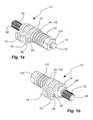
- FIG. 1 ais a rear perspective view of a friction hinge in accordance with an embodiment of the present invention
- FIG. 1 bis a front perspective view of the friction hinge of FIG. 1 a;
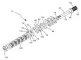
- FIG. 2is an exploded perspective view of the friction hinge of FIG. 1 a;
- FIG. 3is rear view of the friction hinge of FIG. 1 a;
- FIG. 4is a side view of the friction hinge of FIG. 1 a;
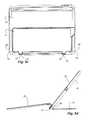
- FIG. 5 ais a keyboard folio with the friction hinge of FIG. 1 a , and shown with a tablet computer therein and shown in a use configuration and with a kickstand in a deployed configuration;
- FIG. 5 bis a side view of the keyboard folio of FIG. 5 a with the friction hinge of FIG. 1 a , and shown in a folded configuration and with the kickstand in a retracted configuration;
- FIG. 5 cis a rear view of the keyboard folio of FIG. 5 a with the friction hinge of FIG. 1 a , and shown with the kickstand in the retracted configuration;
- FIG. 5 dis a side view of the keyboard folio of FIG. 5 a with the friction hinge of FIG. 1 a , and shown in the use configuration and the kickstand in the deployed configuration;
- FIG. 6 ais a partial rear view of the keyboard folio of FIG. 5 a showing the friction hinge of FIG. 1 a being installed;
- FIG. 6 bis a partial rear view of the keyboard folio of FIG. 5 a shown with the friction hinge of FIG. 1 a installed.
- tablette computerand “tablet” are used interchangeably herein to refer to a computer or multi-media device that is one-piece with a screen and that is portable and handheld.
- tabletsinclude the AppleTM iPadTM, the SamsungTM GalaxyTM TabTM, etc.
- the screencan be a touch screen that can receive input by touch, such as finger swipes, and/or can have a virtual keyboard.
- the tabletcan have a battery and memory and a processor with software running thereon.
- the tabletcan have WiFi and Bluetooth connectivity, and can have a wireless transmitter, receiver, or transceiver.
- the tabletcan provide internet browsing, game playing, movie and picture display, c-book display, etc.
- the tabletcan include a digital camera.
- tablet computer and tabletare used broadly herein to refer to cellular or cell phones (or smart phones) and phablets, which also provide similar computing capabilities, battery power, memory, processor, software, WiFi and Bluetooth connectivity, transceiver, touch screen display, digital camera, etc.
- cell phones and phabletsinclude the Apple iPhone, the Samsung Galaxy S phone series, the Samsung Note 3 phablet, HTC One Max, Nokia Lumina 1520, etc.
- interference fitand “friction fit” are terms of art used interchangeably herein to refer to deliberately causing, increasing and/or using friction to deliberately resist movement.
- An interference fit or friction fitis different than and great than the existence of friction. While friction may exist between any two surfaces, is often desirable to do all one can to reduce this friction.
- An interference fit or friction fitcan be distinguished from naturally occurring friction by being actually deliberately caused and increased.
- An interference fitcan be created by dimensioning engaging parts so that their surfaces tightly bear against one another.
- a friction fitcan be created by surface roughness that is rougher.
- An interference fit or friction fitcan be used to describe a connection in which the matching or mating between components is configured to have greater than normal friction and/or interference.
- the present inventionpresents a friction hinge to pivotally couple two members, such as members of a keyboard folio for a tablet computer, and hold or maintain the orientation of the two members with respect to one another while allowing the orientation to be changed by an applied force.
- the two members of the keyboard foliocan include a first member, such as a kickstand, pivotally coupled to a second member, such as a shell receiving a tablet computer therein.
- the kickstandcan pivot from the shell to maintain an inclined angle of the shell, and thus the table, on a support surface.
- the hingecan have an auto-lock function to bias and maintain the orientation of the two members in a predetermined orientation.
- the hingecan bias the kickstand to a retracted orientation or storage configuration against the shell, thus maintaining the kickstand out of the way while the shell, and thus the tablet are held, and until desired for use when it can be deployed, without the need for magnets or other means to hold the kickstand to the shell.
- the hingecan be tailored or customized to provide the desired resistance or torque to adjust the relative orientations of the two members, or kickstand and shell, between different designs.
- the hingecan be formed of hinge components that can be massed produced, and assembled to have different properties for different products suited to different members.
- the hingecan be mounted without brackets and/or other fasteners or screws.
- a hingeindicated generally at 10 , in an example implementation in accordance with the invention is shown.
- the hinge 10can be coupled between first and second members 14 and 18 to resistively hold an orientation between the first and second members at a plurality of orientations.
- the hinge 10can bias the first and second members 14 and 18 in a predetermined set orientation, defining an auto-lock orientation.
- the first member 14can be a kickstand
- the second member 18can be a shell sized and shaped to receive a table computer 22 .
- the kickstandcan be pivotally oriented with respect to the shell by the hinge.
- the predetermined set orientation of the hingecan correspond to a closed storage configuration of the kickstand with the kickstand against the shell.
- the kickstand and shellcan be part of a keyboard folio including a keyboard 26 coupled to the shell, and operatively coupled to the tablet.
- the first member 14 or kickstandcan have a lobe 30 extending into a notch 34 in the second member 18 or shell.
- the lobe 30can have a bore 38 therein with a cross-sectional shape.
- the second member 18 or shellcan have a slot 42 with a cross-sectional shape different than the cross-sectional shape of the bore of the lobe.
- the slot 42can extend from a perimeter side 46 of the second member 18 of shell to the notch 34 .
- the slot 42 of the second member 18can be aligned with the bore 38 of the lobe 30 of the first member 14 or kickstand.
- the slot aligned with the boreallows for installation of the hinge 10 , as discussed in greater detail below.
- the first and second memberscan be formed of plastic, and can be formed by injection molding.
- the hinge 10comprises an elongated shaft 50 having a proximal end 54 and a distal end 58 .
- the distal end of the shaftcan have a head 62 with a cross-sectional shape configured to mate with a shape of the bore 38 in the first member 14 (or lobe of the kickstand) so that the shaft 50 rotates with the first member 14 with respect to the second member 18 .
- the head of the shaftcan be inserted into the bore, and can be held in the bore to rotate with the first member (or with the lobe and the kickstand).
- a cross-sectional shape (taken perpendicularly to an axis of the head or shaft) of the headcan mate with a cross-sectional shape of the bore.
- the head 62can have a cross-sectional shape that is non-circular, such as by having a saw tooth shape with a plurality of teeth extending radially outwardly.
- the borecan have a cross-sectional shape (taken perpendicularly to an axis of the bore) with a saw-tooth shape with a plurality of indentations extending radially outwardly that match and mate with the plurality of teeth.
- the cross-sectional shape of the headdoes not match the cross-sectional shape of the bore.
- the headcan be press-fit in the bore.
- the headcan be adhered in the bore with adhesive.
- the headcan be embedded in the bore, such as by press-fitting or sonic welding.
- the shaft 50also can comprise a shoulder 66 adjacent to or proximate the head 62 .
- the shoulder 66can abut to the first member 14 (or the lobe of the kickstand), and can limit insertion of the head into the bore.
- the shouldercan have a greater width or diameter than the head.
- the shaft 50also comprises an axel portion 70 on the shaft adjacent to or proximal the shoulder.
- the axel portion 70has a cross-sectional shape that is non-circular.
- the axel portioncan be keyed or can have a flat or opposite flats extending into a circumference of the axel portion.
- the proximal end 54 of the shaft 50can be threaded.
- the elongated shaft 50 , along with the head 62 , the shoulder 66 , the axel portion 70 and the threadscan be formed of metal, and can be formed by machining.
- the hinge 10also comprises a key 74 rotatably disposed on the axel portion 70 of the shaft 50 .
- the key 74can comprise a key plate 76 .
- the key 74 or key plate 76has a key ring 78 rotatably disposed on the axel portion 70 of the shaft 50 .
- the key 74 or key plate 76has a tab 82 that extends radially outward (with respect to the axis of the shaft) from the key ring 78 .
- the tab 82has a profile or shape (looking along an axis of the shaft) configured to mate with a shape (looking along an axis of the slot) of the slot 42 in the second member 18 (or shell), so that the key 74 rotates with the second member 18 with respect to the first member 14 .
- the key 74is affixed in the slot 42 , by the mating profiles of the tab 82 and slot 42 , or the tab extending into the slot; while the head 62 is affixed in the bore 38 .
- the key 74 or key plate 76can be formed of metal, and can be formed by stamping or machining.
- the key 74can comprise a plurality of keys or key plates 76 rigidly affixed together, or to one another.
- Each key plate 76has a bore to rotatably receive the shaft 50 therein or therethrough.
- Each key plate 76has a tab 82 extending from a key ring, and an aperture 86 in the tab.
- a rod 90extends through the aperture 86 in each tab 82 of each key plate 76 to rigidly affix the plurality of key plates together.
- the rodcan be a rivet affixed to the outermost key plates. Intermediate washers can be disposed between the tabs, and held by the rod, to resist bending the key plates.
- the key plates 76 affixed togethercan define the key 74 .
- the key plates 76are rigidly affixed to one another, and rotating together as the key 74 on the axel portion 70 of the shaft 50 .
- one or more key plates 76can be stacked or positioned adjacent one another, or bordering and abutting to one another, to increase a length of the key, and thus a width of the combined tabs 82 bearing against a wall of the slot 42 or the second member 18 .
- one or more key platescan be separated, as discussed in greater detail below, to increase friction, and/or to widen the tab. The use of multiple key plates and tabs can allow force from the key to be distributed along the slot and the second member.
- the key 74 and/or key plate 76can have one or more bearing surfaces oriented to face axially with respect to the shaft, or along the axis of the shaft. Opposite sides of the key and/or the key plate can act as the bearing surfaces, so that the key or key plate can have opposite bearing surfaces.
- the bearing surfaces of the key or key platecan be defined by or carried by the key ring 78 or the key or key plate. As the key 74 and/or key plate 76 pivots or rotates on the shaft, the bearing surfaces abut to other bearing surfaces, as described below.
- the hinge 10also comprises a friction ring 94 (which can also be a detent ring as discussed below) disposed on the axel portion 70 of the shaft 50 and proximal the key 74 .
- the friction ring 94is keyed to the shaft and rotatable with the shaft 50 , and with respect to the key 74 .
- the friction ring 94has a bore with a shape that mates with the cross-sectional shape of the axel portion 70 of the shaft 50 . In one aspect, the shape of the bore can match the cross-sectional shape of the axel portion.
- the friction ring 94can be disposed adjacent to and abutting to a key 74 and/or key plate 74 .
- the friction ring 94has a bearing surface oriented to face axially with respect to the shaft, and rotatably abutting to an opposing bearing surface of an adjacent key or key plate.
- the bearing surfaces of the key or key plateabut to and rotate against the bearing surfaces of the friction ring 94 .
- the friction ring 94has a bearing surface rotatably abutting to an opposing bearing surface of an adjacent key or key plate. It is noted that friction is deliberately caused between the opposing bearing surfaces of the friction ring and the key or key plate to hold the relative orientation or position between the abutting friction ring and key or key plate absent an applied force.
- a friction fit or interference fitis formed between the friction ring and key or key plate using friction to deliberately resist movement.
- the friction between the bearing surfaces of the friction ring (or the detent ring) and the key or key platedefines a friction hold orientation (different than a predetermined set orientation defined below in which the detent is disposed in the dimple), in which the key or key plate is held with respect to the shaft by friction between the key or key plate and the friction ring (or detent ring). A lesser amount of force is required to rotate the key or key plate with respect to the shaft.
- the friction ringscan be formed of metal, and can be formed by stamping or machining.
- the friction ring 94can comprise a plurality of friction rings.
- Each friction ringhas a bore with a shape that mates with the cross-sectional shape of the axel portion of the shaft.
- Each friction ringhas a bearing surface rotatably abutting to an opposing bearing surface of an adjacent key plate.
- the friction ring 94can be an intermediate friction ring disposed between adjacent keys 74 or key plates 76 .
- the intermediate friction ringis on the axel portion of the shaft and rotatable with the shaft and with respect to the adjacent key plates.
- the intermediate friction ringhas a bore with a shape that mates with the cross-sectional shape of the axel portion of the shaft.
- the intermediate friction ringhas opposite bearing surfaces rotatably abutting to opposing bearing surfaces of the adjacent key plates.
- the key platecan be an intermediate key plate disposed between adjacent friction plates.
- the intermediate key platehas opposite bearing surfaces rotatably abutting to the opposing bearing surfaces of the adjacent key plates.
- the hingecomprises a stack or a series of key plates and friction rings disposed on the axel portion of the shaft.
- the series of key plates and friction ringscan comprise a plurality of key plates, or a plurality of friction rings, or both.
- the hingecomprises an alternating stack or an alternating series of key plates and friction rings.
- the series of key plates and friction rings(or dentent rings) can comprise at least one key plate and at least two friction rings (or detent rings).
- the key platecan be disposed between the friction rings.
- the series of key plates and friction rings (or dentend rings)can comprise at least two key plates and at least one friction ring (or detent ring).
- the friction ringcan be disposed between the key plates.
- the hinge 10can further comprise a detent ring 102 .
- the friction ring 94can be or can define a detent ring.
- the detent ringcan be separate and discrete from the friction ring.
- the detent ring 102can be disposed on the axel portion 70 of the shaft 50 and proximal the key 74 or key plate 76 .
- the detent ring 102is keyed to the shaft and is rotatable with the shaft 50 , and with respect to the key 74 or key plate 76 .
- the detent ring 102has a bore with a shape that mates with the cross-sectional shape of the axel portion 70 of the shaft 50 . In one aspect, the shape of the bore can match the cross-sectional shape of the axel portion.
- the detent ring 102can be disposed adjacent to and abutting to a key 74 and/or key plate 74 .
- a dimpleis formed in the key ring of the key or the friction ring or the detent ring.
- a dimple 106can be formed in the key ring 78 of the key 74 or key plate 76 (and is so shown for purposes of illustration).
- a dimplecan be formed in the friction ring or the detent ring.
- a detentextends axially from another of the key ring or the friction ring or detent ring, and is removably received within the dimple.
- a detent 110 or protrusioncan extend from the detent ring 102 (or the friction ring), and is removably received within the dimple 106 of the friction ring 78 (as is so shown for purposes of illustration).
- a detentcan extend from the key ring.
- the detent 110 residing in the dimple 106can define a predetermined set orientation (different than the friction hold orientation defined above), and an autolock orientation, between the detent ring (or friction ring) and the key or key plate (and thus the first and second members, or the kickstand and the shell). A greater amount of force is required to rotated the detent out of the dimple, and thus the key out of the predetermined set orientation.
- the detent ring 102can comprise a plurality of detent rings.
- Each detent ringhas a bore with a shape that mates with the cross-sectional shape of the axel portion of the shaft.
- Each detent ringcan have a bearing surface rotatably abutting to an opposing bearing surface of an adjacent key plate.
- each detent ringcan have a detent received in a dimple of an adjacent key ring of a key or key plate.
- the detent ring 102can be an intermediate detent ring disposed between adjacent keys or key plates.
- the intermediate detent ringcan be disposed on the axel portion of the shaft and rotatable with the shaft and with respect to the adjacent key plates.
- the intermediate detent ringcan have a bore with a shape that mates with the cross-sectional shape of the axel portion of the shaft.
- the intermediate detent ringcan have a detent extending axially from the intermediate detent ring and into engagement with the key ring and removably received within the dimple of the key ring.
- the hingecomprises a stack or a series of key plates and detent rings disposed on the axel portion of the shaft.
- the series of key plates and detent ringscan comprise a plurality of key plates, or a plurality of detent rings, or both.
- the hingecomprises an alternating stack or an alternating series of key plates and detent rings.
- the series of key plates and friction rings(or dentent rings) can comprise at least one key plate and at least two friction rings (or detent rings).
- the key platecan be disposed between the friction rings.
- the series of key plates and friction rings (or dentend rings)can comprise at least two key plates and at least one friction ring (or detent ring). The friction ring can be disposed between the key plates.
- the hingecomprises a spring 120 carried by the shaft 50 , and biasing the key 74 or key plate 76 and the friction ring or detent ring together.
- the spring 120biases the detent 110 into engagement with the dimple 106 .
- the hingecan be biased towards the predetermined set orientation or the auto-lock orientation.
- the springis a Belleville spring or Belleville washer, also known as a coned-disc spring, conical spring washer, disc spring, Belleville spring or cupped spring washer.
- the Belleville springis a type of spring shaped like a washer with a frusto-conical shape which gives the washer a spring characteristic.
- the springcan comprise a plurality of Belleville type washers.
- the number of Belleville type washerscan determine the spring constant and/or amount of deflection. Stacking the Belleville type washers in the same direction will add the spring constant in parallel to create a stiffer joint while maintaining the same deflection; while stacking the Belleville type washers in alternating directions will add the spring constant in series to create a lower spring constant with greater deflection. The number and orientation of the Belleville type washers allows a specific spring constant and deflection to be designed.
- the springcan be a coil spring.
- the hinge 10can comprise a fastener 124 , such as a lock nut, disposed on the shaft 50 with the spring 120 between the fastener and the key and/or friction or detent ring.
- the fastener 124can be axially displaceable to vary a force of the spring against the key and the friction/detent ring.
- the fastenercan vary the amount of friction between the key and the friction/detent ring, and thus vary an amount of torque required to pivot the key with respect to the shaft.
- the key 74 and/or key plates 76are held in position with respect to the axel portion 70 of the shaft 50 , and thus the second member 18 is held in position with respect to the first member 14 , by friction between the key 74 or key plates 76 and the friction ring 94 or detent ring 102 .
- the key 74rotates on the shaft between a plurality of different orientations, including at least: a predetermined set orientation, and a friction hold orientation, different than the predetermined set orientation.
- the detent 110is disposed in the dimple 106 , defining an autolock orientation, and a greater amount of force is required to rotated the key out of the predetermined set orientation.
- the detent 110is disposed out of the dimple 106 , and the key is held with respect to the shaft by friction between the key and the friction ring or dentent ring, and a lesser amount of force is required to rotate the key with respect to the shaft.
- the head 62has a cross-sectional shape mating with the cross-sectional shape of the bore 38 of the lobe 30 (of the first member 14 or kickstand) so that the head is fixedly retained within the bore, and with respect to the first member 14 (or kickstand).
- the key 74has a cross-sectional shape mating with the cross-sectional shape of the slot 42 so that the key is fixedly retained within the slot, and with respect to the second member 18 (or shell).
- the cross-sectional size of the slot 42can be larger than a cross-sectional size of the bore 38 .
- the keycan have a cross-sectional size greater than a cross-sectional size of the head.
- the cross-sectional shape of headcan be smaller than cross-sectional shape of the hinge and perimeter profile of head fits within perimeter profile of hinge.
- the hinge 10is capable of being inserted into the slot 42 through the perimeter side 46 (or opening therein to the slot) of the second member 18 (or shell) until the head 62 is retained in the bore 38 of the lobe 30 of the first member 14 (or kickstand), and the key 74 is retained in the slot 42 of the second member 18 .
- the hingeis adapted to facilitate assembly with the first and second members.
Landscapes
- Engineering & Computer Science (AREA)
- Computer Hardware Design (AREA)
- Theoretical Computer Science (AREA)
- Human Computer Interaction (AREA)
- Physics & Mathematics (AREA)
- General Engineering & Computer Science (AREA)
- General Physics & Mathematics (AREA)
- Mechanical Engineering (AREA)
- Pivots And Pivotal Connections (AREA)
Abstract
Description
Claims (19)
Priority Applications (1)
| Application Number | Priority Date | Filing Date | Title |
|---|---|---|---|
| US15/150,665US9557776B1 (en) | 2016-05-10 | 2016-05-10 | Friction resistance hinge with auto-lock |
Applications Claiming Priority (1)
| Application Number | Priority Date | Filing Date | Title |
|---|---|---|---|
| US15/150,665US9557776B1 (en) | 2016-05-10 | 2016-05-10 | Friction resistance hinge with auto-lock |
Publications (1)
| Publication Number | Publication Date |
|---|---|
| US9557776B1true US9557776B1 (en) | 2017-01-31 |
Family
ID=57867490
Family Applications (1)
| Application Number | Title | Priority Date | Filing Date |
|---|---|---|---|
| US15/150,665Expired - Fee RelatedUS9557776B1 (en) | 2016-05-10 | 2016-05-10 | Friction resistance hinge with auto-lock |
Country Status (1)
| Country | Link |
|---|---|
| US (1) | US9557776B1 (en) |
Cited By (7)
| Publication number | Priority date | Publication date | Assignee | Title |
|---|---|---|---|---|
| CN107608450A (en)* | 2017-08-10 | 2018-01-19 | 联想(北京)有限公司 | Attachment means and electronic equipment |
| US10268240B2 (en)* | 2016-09-01 | 2019-04-23 | Acer Incorporated | Supporting assembly |
| US10324501B1 (en)* | 2018-07-20 | 2019-06-18 | Apple Inc. | Hinge assembly with layered friction elements |
| US20190292827A1 (en)* | 2018-03-21 | 2019-09-26 | Microsoft Technology Licensing, Llc | Low-pressure friction hinge |
| CN110499979A (en)* | 2018-05-16 | 2019-11-26 | 无锡小天鹅电器有限公司 | Door-hinge component and washing machine |
| US10606321B2 (en) | 2017-06-27 | 2020-03-31 | Microsoft Technology Licensing, Llc | Systems and methods of lateral torsional resistance in a hinge |
| US11009918B2 (en) | 2018-01-05 | 2021-05-18 | Zagg Intellectual Property Holding Co., Inc. | Keyboard folio with magnetic attachment |
Citations (187)
| Publication number | Priority date | Publication date | Assignee | Title |
|---|---|---|---|---|
| US676449A (en) | 1900-12-19 | 1901-06-18 | Hans Schwarz | Gas, petroleum, or like internal-combustion engine. |
| US4259568A (en) | 1979-10-12 | 1981-03-31 | Henning Dynesen A/S | Combined casing and operational support for a pocket calculator |
| USD279185S (en) | 1982-10-25 | 1985-06-11 | At&T Bell Laboratories | Stand for a telephone or similar article |
| US5375076A (en) | 1993-09-10 | 1994-12-20 | Compaq Computer Corporation | Combined notepad and notebook computer |
| US5383139A (en) | 1992-04-24 | 1995-01-17 | Matsushita Electric Industrial Co., Ltd. | Electronic apparatus |
| US5383138A (en) | 1992-07-13 | 1995-01-17 | Fujitsu Limited | Folding portable data processing apparatus with three hinge points |
| US5457453A (en) | 1992-06-15 | 1995-10-10 | Chiu; Wilson L. | Folding keyboard |
| US5594619A (en) | 1990-04-27 | 1997-01-14 | Kabushiki Kaisha Toshiba | Portable computer comprising keyboard and coordinate input tablet hingedly connected to a main body case through a junction base having a cylindrical element defining a linear groove therethrough |
| US5666694A (en) | 1995-09-28 | 1997-09-16 | Hewlett-Packard Company | Hinge arrangement |
| US5737183A (en) | 1995-05-12 | 1998-04-07 | Ricoh Company, Ltd. | Compact portable computer having a riser that forms when a cover is opened |
| US5847698A (en) | 1996-09-17 | 1998-12-08 | Dataventures, Inc. | Electronic book device |
| US5987704A (en) | 1998-04-15 | 1999-11-23 | Apple Computer, Inc. | Dual axis hinge apparatus with braking mechanism |
| US6144551A (en) | 1998-10-20 | 2000-11-07 | Peripheral Technology Inc. | Data input device with foldable cover |
| US6219230B1 (en) | 1998-12-01 | 2001-04-17 | Samsung Electronics Co., Ltd. | Portable computer with improved assembly design |
| US6253419B1 (en) | 2000-01-13 | 2001-07-03 | Lu Sheng-Nan | Pivot device with multiple pivotal bars for a notebook computer |
| US20010009500A1 (en) | 1999-10-06 | 2001-07-26 | International Business Machines Corporation | Notebook computer having a resilient, portfolio-type case |
| US6304433B2 (en) | 1999-08-30 | 2001-10-16 | Dell Usa, L.P. | Portable computer having a sealed hinge clutch |
| US20010040559A1 (en) | 1994-02-24 | 2001-11-15 | Bullister Edward T. | Collapsible portable electronic device with display |
| US20020033761A1 (en) | 2000-09-21 | 2002-03-21 | Seiki Katakami | Folding keyboard |
| US6370018B1 (en) | 2000-08-18 | 2002-04-09 | William B. Miller, Jr. | Portable computer keyboard |
| USD457525S1 (en) | 1999-04-02 | 2002-05-21 | Think Outside, Inc. | Folding keyboard |
| US6457996B1 (en) | 2001-06-22 | 2002-10-01 | Jess-Link Products Co., Ltd. | Connector to PDA external keyboard |
| US20020159226A1 (en) | 2001-04-30 | 2002-10-31 | Chi-Te Huang | External keyboard for personal digital assistant |
| US6493216B1 (en) | 1999-10-20 | 2002-12-10 | Arima Computer Corp. | Portable computer with an LCD which can be rotated within 360 degrees |
| US6498718B1 (en) | 1998-10-23 | 2002-12-24 | Lg. Philips Lcd Co., Ltd. | Portable computer and method for mounting a flat panel display device thereon |
| US6498720B2 (en) | 2001-01-04 | 2002-12-24 | Cirque Corporation | Connector and support system for a touchpad keyboard for use with portable electronic appliances |
| US20030017746A1 (en) | 2001-07-13 | 2003-01-23 | Dataplus Supplies, Inc. | Adaptor to connect handheld computing devices to peripheral devices |
| US6517129B1 (en) | 2002-04-15 | 2003-02-11 | Compal Electronics, Inc. | Lock device for an electronic appliance |
| US20030048595A1 (en) | 2001-09-10 | 2003-03-13 | Omniwin Corp. | Collapsible keyboard |
| US20030112590A1 (en) | 2001-12-17 | 2003-06-19 | Toshiba America Information Systems, Inc. | Portable computer usable in a laptop and tablet configurations |
| US20030112585A1 (en) | 2001-12-13 | 2003-06-19 | Silvester Kelan Craig | Multiprocessor notebook computer with a tablet PC conversion capability |
| US6614649B1 (en) | 2000-09-14 | 2003-09-02 | Sen-Cheng Wang | Keyboard structure of personal digital assistant (PDA) |
| US20030198008A1 (en) | 2002-04-18 | 2003-10-23 | Gateway, Inc. | Computer having detachable wireless independently operable computer |
| US20040004809A1 (en) | 2002-06-25 | 2004-01-08 | Brother Kogyo Kabushiki Kaisha | Foldable keyboard |
| US20040033096A1 (en) | 2002-08-16 | 2004-02-19 | Su-Duek Choi | Portable keyboard |
| US6694570B2 (en) | 2002-03-11 | 2004-02-24 | Compal Electronics, Inc. | Hinge device |
| US6700775B1 (en) | 2002-11-22 | 2004-03-02 | Compal Electronics, Inc. | Portable electronic apparatus having a cover device with a stand unit for supporting a user interface device |
| US20040114315A1 (en) | 2002-12-17 | 2004-06-17 | Nokia Corporation | Convertible mobile computing device |
| US20040136149A1 (en) | 2003-01-13 | 2004-07-15 | Tatung Co., Ltd. | Portable computer having a hidden keyboard structure |
| US6768635B2 (en) | 2001-11-06 | 2004-07-27 | Inventec Appliances Corp. | Hand-held electronic device with hidden keyboard |
| US6771494B2 (en) | 2001-12-17 | 2004-08-03 | Toshiba America Information Systems, Inc. | Portable computer usable in laptop and tablet configurations |
| US6774888B1 (en) | 2000-06-19 | 2004-08-10 | International Business Machines Corporation | Personal digital assistant including a keyboard which also acts as a cover |
| US20040159762A1 (en) | 2003-02-14 | 2004-08-19 | Prosenjit Ghosh | Tablet computer system with a detatchable base |
| US20040160735A1 (en) | 2003-02-14 | 2004-08-19 | Prosenjit Ghosh | Convertible and detachable laptops |
| US6785128B1 (en) | 1999-06-11 | 2004-08-31 | Samsung Electronics Co., Ltd | Portable computer having cover support means |
| US20040195305A1 (en) | 2002-11-19 | 2004-10-07 | Leslie Dotson | Foldable key assembly |
| US20040209489A1 (en) | 2003-04-21 | 2004-10-21 | Clapper Edward O. | Apparatus for automatic docking |
| US20040212954A1 (en) | 2003-04-25 | 2004-10-28 | Motion Computing, Inc. | Combined modular keyboard and tablet PC protective cover |
| US20040232302A1 (en) | 2003-03-10 | 2004-11-25 | Tatung Co., Ltd. | Support structure of a portable keyboard |
| US20050052831A1 (en) | 2003-09-08 | 2005-03-10 | Inventec Corporation | Lift-back tablet computer background of the invention |
| US6898073B2 (en) | 2002-12-31 | 2005-05-24 | Mitach International | Hand-held electronic device |
| US20050122671A1 (en) | 2003-12-09 | 2005-06-09 | Homer Steven S. | Electronic device with improved hinge |
| US20050146446A1 (en) | 2004-01-07 | 2005-07-07 | Darfon Electronics Corp. | Keyboards |
| US20050155182A1 (en) | 2004-01-20 | 2005-07-21 | Young-Soo Han | Hinge device |
| US20050168925A1 (en) | 2004-01-30 | 2005-08-04 | First International Computer Inc. | Separable and foldable tablet PC assembly |
| US6937468B2 (en) | 2003-11-20 | 2005-08-30 | Tatung Co., Ltd. | Portable computer and portable docking station arrangement |
| US20050236869A1 (en) | 2004-04-09 | 2005-10-27 | Sung-Hyun Ka | Portable apparatus having two rotatable and foldable units and hinge device used for the same |
| US20060007645A1 (en) | 2004-07-09 | 2006-01-12 | Tatung Co., Ltd. | Foldable computer cover |
| US20060044288A1 (en) | 2004-06-18 | 2006-03-02 | Hiroshi Nakamura | Multi-functional electronic device utilizing a stylus pen |
| US7017243B2 (en) | 2003-08-07 | 2006-03-28 | Carnevali Jeffrey D | Secure interface cradle for pocket personal computer device |
| US20060071820A1 (en) | 2002-10-21 | 2006-04-06 | Lichen Wang | Universal mobile keyboard |
| US7042712B2 (en) | 2003-09-15 | 2006-05-09 | Intel Corporation | Extended stand computer system with retractable keyboard |
| US20060152894A1 (en) | 2004-12-15 | 2006-07-13 | Christian Moengen | Collapsible multimedia endpoint |
| US20060152897A1 (en) | 2003-09-12 | 2006-07-13 | Fujitsu Limited | Screen display method of information processing device, information processing device and its storage medium |
| US7082642B2 (en)* | 2004-06-18 | 2006-08-01 | Sinher Technology Inc. | Hinge for anchoring and folding on a small pintle |
| US7085129B2 (en) | 2003-04-17 | 2006-08-01 | Darfon Electronics Corp. | Support apparatus |
| US20060214916A1 (en) | 2003-03-20 | 2006-09-28 | Andrew Mulford | Miniaturised keyboard |
| US7123242B1 (en) | 1998-04-24 | 2006-10-17 | Henty David L | Remote control method using remote control device with keyboard |
| US7129931B2 (en) | 2001-09-14 | 2006-10-31 | Pappas Nicholas J | Multipurpose computer display system |
| US20060256511A1 (en) | 2005-05-12 | 2006-11-16 | Yan-Bin Ma | Tablet computer stander apparatus with keyboard room space thereof |
| US20060262496A1 (en) | 2005-05-23 | 2006-11-23 | Seung-Won Lee | Portable computer having detachable display |
| US20060264243A1 (en) | 2005-05-17 | 2006-11-23 | Nokia Corporation | Display changing in a portable electronic device |
| US20070008291A1 (en) | 2005-07-05 | 2007-01-11 | Darfon Electronics Corporation | Foldable keyboard |
| US20070091553A1 (en) | 2005-10-04 | 2007-04-26 | Asustek Computer Inc. | Overturn structure of a dual-usage computer |
| US20070097087A1 (en) | 2005-10-31 | 2007-05-03 | Homer Steven S | Tablet computer overlay membrane |
| US7222396B2 (en)* | 2005-03-09 | 2007-05-29 | Shin Zu Shing Co., Ltd | Robust hinge |
| US20070203963A1 (en) | 2006-02-11 | 2007-08-30 | Hon Hai Precision Industry Co., Ltd. | Portable computer |
| US7318521B2 (en) | 2004-09-21 | 2008-01-15 | Creative Technology Ltd | Pouch with integrated stand |
| US20080084396A1 (en) | 2006-10-04 | 2008-04-10 | Arima Computer Corporation | Tablet PC and method for keyboard containing the same |
| US20080119250A1 (en) | 2006-11-22 | 2008-05-22 | Samsung Techwin Co., Ltd. | Magnetic levitation sliding structure |
| US20080125200A1 (en) | 2006-11-27 | 2008-05-29 | Park Hyo-Sung | Portable electronic device |
| US20080139261A1 (en) | 2006-12-07 | 2008-06-12 | Samsung Techwin Co., Ltd. | Magnetic levitation sliding structure |
| US7393151B1 (en) | 2005-08-18 | 2008-07-01 | Miller Jr William B | Portable computer keyboard |
| US20080176610A1 (en) | 2007-01-22 | 2008-07-24 | Qisda Corporation | Foldable mobile electronic device |
| US20080194139A1 (en) | 2007-02-12 | 2008-08-14 | Belkin International, Inc | Case for electrical device and method of using same |
| US20080225471A1 (en) | 2007-03-16 | 2008-09-18 | Fujitsu Limited | Housing protective cover and electronic apparatus system |
| US20080273012A1 (en) | 2004-02-23 | 2008-11-06 | Edward Bullister | Multifunctional portable computing device with special housing |
| US20090000062A1 (en) | 2006-01-24 | 2009-01-01 | Kabushiki Kaisha Strawberry Corporation | Hinge Device and Electronic Device Using Hinge Device |
| US7477508B1 (en) | 2008-04-29 | 2009-01-13 | International Business Machines Corporation | Combination keyboard and digital tablet |
| US20090017883A1 (en) | 2007-07-13 | 2009-01-15 | Tso Wei Lin | Cell phone case |
| US7484271B2 (en) | 2003-04-03 | 2009-02-03 | Sugatsune Kogyo Co., Ltd. | Device case opening/closing device, and 2-axis hinge device |
| US20090056073A1 (en) | 2007-09-03 | 2009-03-05 | Shin Zu Shing Co., Ltd. | Hinge |
| US7502225B2 (en) | 2004-09-17 | 2009-03-10 | Hewlett-Packard Development Company, L.P. | Portable computer docking station |
| US20090086424A1 (en) | 2007-10-01 | 2009-04-02 | Raymond Jette | Tri-layer folding laptop computer |
| US7520026B1 (en)* | 2008-02-05 | 2009-04-21 | Leohab Enterprise Co., Ltd. | Hinge assembly |
| US7520027B2 (en)* | 2005-12-28 | 2009-04-21 | Shin Zu Shing Co., Ltd. | Friction enhanced hinge to provide positioning force to hold a display at a position as required |
| US7520025B2 (en)* | 2007-07-31 | 2009-04-21 | Shin Zu Shing Co., Ltd. | Hinge for a notebook extension pad |
| US7533446B1 (en)* | 2007-11-15 | 2009-05-19 | Shin Zu Shing Co., Ltd. | Variable resistance hinge |
| US7541907B2 (en) | 2005-11-07 | 2009-06-02 | High Tech Computer Corp. | Auto-aligning and connecting structure between electronic device and accessory |
| US7583500B2 (en) | 2005-12-13 | 2009-09-01 | Apple Inc. | Electronic device having magnetic latching mechanism |
| US7603747B2 (en)* | 2006-01-26 | 2009-10-20 | Jarllytec Co., Ltd. | Rotating shaft structure with automatic locking mechanism |
| US7612989B2 (en) | 2001-01-30 | 2009-11-03 | Palm, Inc. | Segmented keyboard for portable computer system |
| US7626357B2 (en) | 2007-02-07 | 2009-12-01 | Eveready Battery Co., Inc. | Battery charger having a spring loaded plunger contact mechanism |
| US7672699B2 (en) | 2003-06-19 | 2010-03-02 | Samsung Electronics Co., Ltd. | Driving apparatus using magnetic substance for sliding type portable wireless terminal |
| US7669286B2 (en)* | 2006-01-31 | 2010-03-02 | Shin Zu Shing Co., Ltd. | Pivotal hinge |
| USD611045S1 (en) | 2008-10-10 | 2010-03-02 | Apple Inc. | Portable computer |
| US7685679B2 (en)* | 2007-07-03 | 2010-03-30 | Jamie Horng | Pivotal hinge with an oil-retaining collar |
| US20100123663A1 (en) | 2008-11-14 | 2010-05-20 | Quanta Computer Inc. | Wireless keyboard base and portable electronic device |
| US7730587B2 (en) | 2006-03-01 | 2010-06-08 | Quanta Computer Inc. | Hinge apparatus |
| US20100141588A1 (en) | 2005-10-24 | 2010-06-10 | Fujitsu Limited | Portable electronic apparatus |
| US20100157518A1 (en) | 2008-12-24 | 2010-06-24 | Research In Motion Limited | Multiple-fold portable electronic device |
| US20100172081A1 (en) | 2009-01-05 | 2010-07-08 | Lenovo (Beijing) Limited | Removable portable computer device |
| USD620001S1 (en) | 2008-10-30 | 2010-07-20 | Dell Products L.P. | Portable information handling system |
| US20100195279A1 (en) | 2007-07-18 | 2010-08-05 | Blue Bee Limited | Docking station and kit for a personal electronic device |
| US7823254B2 (en)* | 2008-02-15 | 2010-11-02 | Leohab Enterprise Co.,Ltd. | Hinge assembly |
| US20100294909A1 (en) | 2006-03-23 | 2010-11-25 | Hauser Stephen G | Deployable support unit for reading material |
| US7870644B2 (en)* | 2008-07-01 | 2011-01-18 | Hon Hai Precision Industry Co., Ltd. | Hinge and interference assembly thereof |
| USD637596S1 (en) | 2010-01-06 | 2011-05-10 | Apple Inc. | Portable display device |
| US7966040B2 (en) | 2007-11-08 | 2011-06-21 | Symbol Technologies, Inc. | Magnetically attachable accessories for a mobile unit |
| US7987556B2 (en)* | 2008-07-04 | 2011-08-02 | Hon Hai Precision Industry Co., Ltd. | Hinge and interference apparatus for the same |
| US7992255B2 (en)* | 2008-07-04 | 2011-08-09 | Hon Hai Precision Industry Co., Ltd. | Hinge and interference apparatus for the same |
| USD643433S1 (en) | 2010-10-14 | 2011-08-16 | Cheng Uei Precision Industry Co., Ltd. | Sleeve for tablet PC |
| US20110199727A1 (en) | 2010-01-28 | 2011-08-18 | Brian Probst | Tablet computer case and associated methods |
| US8015668B2 (en)* | 2008-09-12 | 2011-09-13 | Hong Fu Jin Precision Industry (Shenzhen) Co., Ltd. | Hinge assembly |
| US20110222238A1 (en) | 2010-03-15 | 2011-09-15 | Over The Sun, Llc | Housing for slate tablet computer |
| US20110267757A1 (en) | 2010-01-28 | 2011-11-03 | Brian Hullinger Probst | Tablet computer case and associated methods |
| US8082626B2 (en)* | 2009-05-25 | 2011-12-27 | Sinher Technology Inc. | Hinge for anchoring and automatic closing |
| US20120008299A1 (en) | 2010-07-08 | 2012-01-12 | David Gengler | System and apparatus for protecting a mobile device |
| US20120009000A1 (en) | 2010-07-07 | 2012-01-12 | Scott Starrett | Compact keyboard and cradle |
| US20120008269A1 (en) | 2010-07-08 | 2012-01-12 | David Gengler | Protective cover for a mobile computing device, systems including protective covers, and associated methods |
| US20120012483A1 (en) | 2010-07-13 | 2012-01-19 | Eagle Fan | Protective apparatus for tablet electronic device |
| USD652831S1 (en) | 2011-01-18 | 2012-01-24 | Samsung Electronics Co., Ltd. | Netbook computer |
| US8139357B2 (en) | 2009-09-22 | 2012-03-20 | Trang Brian T | Laptop elevation device |
| US8143983B1 (en) | 2010-09-17 | 2012-03-27 | Apple Inc. | Electronic device with magnetic attachment |
| US20120074271A1 (en) | 2010-09-24 | 2012-03-29 | Helmut Goetz | Electronic book, tablet computer and smart phone stand |
| US20120106078A1 (en) | 2010-01-28 | 2012-05-03 | Brian Hullinger Probst | Tablet Computer Case and Associated Methods |
| USD659139S1 (en) | 2010-07-08 | 2012-05-08 | Zagg Intellectual Property Holding Co., Inc. | Protective cover, including keyboard, for mobile computing device |
| US20120114198A1 (en) | 2010-11-08 | 2012-05-10 | Yang Ting-Ting | Facial image gender identification system and method thereof |
| US20120140396A1 (en) | 2010-12-07 | 2012-06-07 | Zachary Joseph Zeliff | Tablet pc cover with integral keyboard |
| US8196262B2 (en)* | 2010-01-26 | 2012-06-12 | Hon Hai Precision Industry Co., Ltd. | Hinge |
| US20120170198A1 (en) | 2010-12-30 | 2012-07-05 | Hon Hai Precision Industry Co., Ltd. | Foldable keyboard |
| US20120188697A1 (en) | 2011-01-25 | 2012-07-26 | Compal Electronics, Inc. | Docking station and electronic apparatus using the same |
| US8230992B2 (en) | 2010-03-15 | 2012-07-31 | Speculative Product Design, Llc | Tablet computer case for multiple viewing orientations |
| US20120194448A1 (en) | 2011-01-31 | 2012-08-02 | Apple Inc. | Cover attachment with flexible display |
| US8253595B2 (en) | 2009-04-24 | 2012-08-28 | Fih (Hong Kong) Limited | Portable electronic device with protective cover for keypad |
| US20120243149A1 (en) | 2011-03-24 | 2012-09-27 | Nokia Corporation | Electronic apparatus with a detachable display |
| US20120293953A1 (en) | 2011-05-20 | 2012-11-22 | Primax Electronics Ltd. | Storage device for tablet personal computer |
| USD671541S1 (en) | 2011-06-23 | 2012-11-27 | Zagg Intellectual Property Holding Co., Inc. | Keyboard for portable electronic device |
| USD672352S1 (en) | 2010-07-08 | 2012-12-11 | Zagg Intellectual Property Holding Co., Inc. | Support element of a protective cover for a mobile computing device |
| US20120327580A1 (en) | 2011-06-23 | 2012-12-27 | Zagg Intellectual Property Holding Co., Inc. | Protective devices and systems for portable electronic devices and associated methods |
| US20120327594A1 (en) | 2011-06-23 | 2012-12-27 | Zagg Intellectual Property Holding Co., Inc. | Accessory and support for electronic devices, systems including the same and methods |
| USD673574S1 (en) | 2011-11-09 | 2013-01-01 | Zagg Intellectual Property Holding Co., Inc. | Portable keyboard |
| USD676031S1 (en) | 2010-08-25 | 2013-02-12 | Zagg Intellectual Property Holding Co., Inc. | Protective cover for a mobile computing device |
| USD676448S1 (en) | 2011-08-18 | 2013-02-19 | NClosures, Inc. | Display tablet enclosure |
| USD676449S1 (en) | 2011-10-28 | 2013-02-19 | Cruxcase, Llc | Tablet computer case |
| USD676853S1 (en) | 2011-11-09 | 2013-02-26 | Zagg Intellectual Property Holding Co., Inc. | Support for portable electronic device |
| US8385063B2 (en) | 2009-07-16 | 2013-02-26 | Hong Fu Jin Precision Industry (Shenzhen) Co., Ltd. | Electronic device |
| USD678885S1 (en) | 2011-06-23 | 2013-03-26 | Zagg Intellectual Property Holding Co., Inc. | Support structure for portable electronic device |
| USD679277S1 (en) | 2011-10-27 | 2013-04-02 | Cruxcase, Llc | Tablet computer case |
| US20130088431A1 (en) | 2011-10-11 | 2013-04-11 | Nokia Corporation | Apparatus Cover with Keyboard |
| USD682274S1 (en) | 2011-06-23 | 2013-05-14 | Zagg Intellectual Property Holding Co., Inc. | Keyboard |
| US20130134061A1 (en) | 2011-11-25 | 2013-05-30 | Primax Electronics Ltd. | Storing mechanism for electronic device |
| USD684963S1 (en) | 2011-02-08 | 2013-06-25 | Scott Goodrich | Cellular phone holder |
| US20130170126A1 (en) | 2012-01-03 | 2013-07-04 | Samsung Electronics Co., Ltd. | Mobile apparatus |
| USD689054S1 (en) | 2012-01-09 | 2013-09-03 | 3M Innovative Properties Company | Foldable case for a tablet electronic device |
| US20130229354A1 (en) | 2012-03-02 | 2013-09-05 | David Otto Whitt, III | Flexible hinge support layer |
| US20130242490A1 (en) | 2012-03-13 | 2013-09-19 | Allen Ku | Leather case and hand-held device having touch panel |
| US20130242492A1 (en) | 2012-03-16 | 2013-09-19 | Research In Motion Limited | Foldable keyboard |
| US8542495B1 (en) | 2011-08-18 | 2013-09-24 | NClosures, Inc. | Security enclosure for tablet display devices |
| US20130279096A1 (en) | 2010-07-08 | 2013-10-24 | Zagg Intellectual Property Holding Co., Inc. | Protective cover for portable electronic device and associated systems and methods |
| USD692886S1 (en) | 2012-04-11 | 2013-11-05 | Logitech Europe S.A. | Folio keyboard for tablet computer |
| US20130301205A1 (en) | 2011-02-04 | 2013-11-14 | Research In Motion Limited | Magnetic slider mechanism for electronic devices and methods of use |
| USD694248S1 (en) | 2011-04-06 | 2013-11-26 | Guy Monroe Van Natta | Stand for tablet computers and e-readers |
| US8599542B1 (en) | 2013-05-17 | 2013-12-03 | Zagg Intellectual Property Holding Co., Inc. | Combined cover, keyboard and stand for tablet computer with reversable connection for keyboard and reading configuration |
| US20140043743A1 (en) | 2012-08-08 | 2014-02-13 | Wistron Corporation | Portable electronic device |
| US20140055920A1 (en) | 2012-08-23 | 2014-02-27 | Dexin Corporation | Flip-type electronic device |
| US20140071654A1 (en) | 2012-09-11 | 2014-03-13 | Logitech Europe S.A. | Protective Cover for a Tablet Computer |
| USD701210S1 (en) | 2012-04-11 | 2014-03-18 | Logitech Europe S.A. | Protective cover for a tablet computer |
| USD701857S1 (en) | 2012-08-01 | 2014-04-01 | Ebsco Industries, Inc | Media holder |
| US8817457B1 (en) | 2014-01-02 | 2014-08-26 | ZAGG Intellectual Property Holding Co. | Reversible folio for tablet computer with reversible connection for keyboard and reading configuration |
| US8837131B1 (en)* | 2013-11-20 | 2014-09-16 | Zagg Intellectual Property Holding Co., Inc. | Keyboard and folio with size adjustment for tablet computer |
| USD714790S1 (en) | 2012-06-22 | 2014-10-07 | Nlu Products, L.L.C. | Tablet computer case |
| USD722057S1 (en) | 2013-02-18 | 2015-02-03 | Clamcase, Llc | Tablet device case |
| USD727917S1 (en) | 2013-09-04 | 2015-04-28 | Samsung Electronics Co., Ltd. | Case for electronic device |
| US9172419B2 (en) | 2014-02-14 | 2015-10-27 | Primax Electronics Ltd. | Protecting device for tablet computer |
| US20150342067A1 (en)* | 2014-05-20 | 2015-11-26 | Microsoft Corporation | Friction hinge for tablet computers |
| US20150362962A1 (en)* | 2013-03-14 | 2015-12-17 | Hewlett-Packard Development Company, L.P. | Electronic display system with a support stand |
- 2016
- 2016-05-10USUS15/150,665patent/US9557776B1/ennot_activeExpired - Fee Related
Patent Citations (200)
| Publication number | Priority date | Publication date | Assignee | Title |
|---|---|---|---|---|
| US676449A (en) | 1900-12-19 | 1901-06-18 | Hans Schwarz | Gas, petroleum, or like internal-combustion engine. |
| US4259568A (en) | 1979-10-12 | 1981-03-31 | Henning Dynesen A/S | Combined casing and operational support for a pocket calculator |
| USD279185S (en) | 1982-10-25 | 1985-06-11 | At&T Bell Laboratories | Stand for a telephone or similar article |
| US5594619A (en) | 1990-04-27 | 1997-01-14 | Kabushiki Kaisha Toshiba | Portable computer comprising keyboard and coordinate input tablet hingedly connected to a main body case through a junction base having a cylindrical element defining a linear groove therethrough |
| US5383139A (en) | 1992-04-24 | 1995-01-17 | Matsushita Electric Industrial Co., Ltd. | Electronic apparatus |
| US5457453A (en) | 1992-06-15 | 1995-10-10 | Chiu; Wilson L. | Folding keyboard |
| US5383138A (en) | 1992-07-13 | 1995-01-17 | Fujitsu Limited | Folding portable data processing apparatus with three hinge points |
| US5375076A (en) | 1993-09-10 | 1994-12-20 | Compaq Computer Corporation | Combined notepad and notebook computer |
| US20010040559A1 (en) | 1994-02-24 | 2001-11-15 | Bullister Edward T. | Collapsible portable electronic device with display |
| US5737183A (en) | 1995-05-12 | 1998-04-07 | Ricoh Company, Ltd. | Compact portable computer having a riser that forms when a cover is opened |
| US5666694A (en) | 1995-09-28 | 1997-09-16 | Hewlett-Packard Company | Hinge arrangement |
| US5847698A (en) | 1996-09-17 | 1998-12-08 | Dataventures, Inc. | Electronic book device |
| US5987704A (en) | 1998-04-15 | 1999-11-23 | Apple Computer, Inc. | Dual axis hinge apparatus with braking mechanism |
| US7123242B1 (en) | 1998-04-24 | 2006-10-17 | Henty David L | Remote control method using remote control device with keyboard |
| US6144551A (en) | 1998-10-20 | 2000-11-07 | Peripheral Technology Inc. | Data input device with foldable cover |
| US6498718B1 (en) | 1998-10-23 | 2002-12-24 | Lg. Philips Lcd Co., Ltd. | Portable computer and method for mounting a flat panel display device thereon |
| US6219230B1 (en) | 1998-12-01 | 2001-04-17 | Samsung Electronics Co., Ltd. | Portable computer with improved assembly design |
| USD457525S1 (en) | 1999-04-02 | 2002-05-21 | Think Outside, Inc. | Folding keyboard |
| US6785128B1 (en) | 1999-06-11 | 2004-08-31 | Samsung Electronics Co., Ltd | Portable computer having cover support means |
| US6304433B2 (en) | 1999-08-30 | 2001-10-16 | Dell Usa, L.P. | Portable computer having a sealed hinge clutch |
| US20010009500A1 (en) | 1999-10-06 | 2001-07-26 | International Business Machines Corporation | Notebook computer having a resilient, portfolio-type case |
| US6493216B1 (en) | 1999-10-20 | 2002-12-10 | Arima Computer Corp. | Portable computer with an LCD which can be rotated within 360 degrees |
| US6253419B1 (en) | 2000-01-13 | 2001-07-03 | Lu Sheng-Nan | Pivot device with multiple pivotal bars for a notebook computer |
| US6774888B1 (en) | 2000-06-19 | 2004-08-10 | International Business Machines Corporation | Personal digital assistant including a keyboard which also acts as a cover |
| US6370018B1 (en) | 2000-08-18 | 2002-04-09 | William B. Miller, Jr. | Portable computer keyboard |
| US6614649B1 (en) | 2000-09-14 | 2003-09-02 | Sen-Cheng Wang | Keyboard structure of personal digital assistant (PDA) |
| US20020033761A1 (en) | 2000-09-21 | 2002-03-21 | Seiki Katakami | Folding keyboard |
| US6498720B2 (en) | 2001-01-04 | 2002-12-24 | Cirque Corporation | Connector and support system for a touchpad keyboard for use with portable electronic appliances |
| US7612989B2 (en) | 2001-01-30 | 2009-11-03 | Palm, Inc. | Segmented keyboard for portable computer system |
| US20020159226A1 (en) | 2001-04-30 | 2002-10-31 | Chi-Te Huang | External keyboard for personal digital assistant |
| US6457996B1 (en) | 2001-06-22 | 2002-10-01 | Jess-Link Products Co., Ltd. | Connector to PDA external keyboard |
| US20030017746A1 (en) | 2001-07-13 | 2003-01-23 | Dataplus Supplies, Inc. | Adaptor to connect handheld computing devices to peripheral devices |
| US20030048595A1 (en) | 2001-09-10 | 2003-03-13 | Omniwin Corp. | Collapsible keyboard |
| US7129931B2 (en) | 2001-09-14 | 2006-10-31 | Pappas Nicholas J | Multipurpose computer display system |
| US6768635B2 (en) | 2001-11-06 | 2004-07-27 | Inventec Appliances Corp. | Hand-held electronic device with hidden keyboard |
| US20030112585A1 (en) | 2001-12-13 | 2003-06-19 | Silvester Kelan Craig | Multiprocessor notebook computer with a tablet PC conversion capability |
| US20030112590A1 (en) | 2001-12-17 | 2003-06-19 | Toshiba America Information Systems, Inc. | Portable computer usable in a laptop and tablet configurations |
| US6771494B2 (en) | 2001-12-17 | 2004-08-03 | Toshiba America Information Systems, Inc. | Portable computer usable in laptop and tablet configurations |
| US6694570B2 (en) | 2002-03-11 | 2004-02-24 | Compal Electronics, Inc. | Hinge device |
| US6517129B1 (en) | 2002-04-15 | 2003-02-11 | Compal Electronics, Inc. | Lock device for an electronic appliance |
| US20030198008A1 (en) | 2002-04-18 | 2003-10-23 | Gateway, Inc. | Computer having detachable wireless independently operable computer |
| US6920039B2 (en) | 2002-06-25 | 2005-07-19 | Brother Kogyo Kabushiki Kaisha | Foldable keyboard |
| US20040004809A1 (en) | 2002-06-25 | 2004-01-08 | Brother Kogyo Kabushiki Kaisha | Foldable keyboard |
| US20040033096A1 (en) | 2002-08-16 | 2004-02-19 | Su-Duek Choi | Portable keyboard |
| US20060071820A1 (en) | 2002-10-21 | 2006-04-06 | Lichen Wang | Universal mobile keyboard |
| US20040195305A1 (en) | 2002-11-19 | 2004-10-07 | Leslie Dotson | Foldable key assembly |
| US6700775B1 (en) | 2002-11-22 | 2004-03-02 | Compal Electronics, Inc. | Portable electronic apparatus having a cover device with a stand unit for supporting a user interface device |
| US20040114315A1 (en) | 2002-12-17 | 2004-06-17 | Nokia Corporation | Convertible mobile computing device |
| US6898073B2 (en) | 2002-12-31 | 2005-05-24 | Mitach International | Hand-held electronic device |
| US20040136149A1 (en) | 2003-01-13 | 2004-07-15 | Tatung Co., Ltd. | Portable computer having a hidden keyboard structure |
| US20040169995A1 (en) | 2003-02-14 | 2004-09-02 | Prosenjit Ghosh | Convertible and detachable laptops |
| US20040160735A1 (en) | 2003-02-14 | 2004-08-19 | Prosenjit Ghosh | Convertible and detachable laptops |
| US20040159762A1 (en) | 2003-02-14 | 2004-08-19 | Prosenjit Ghosh | Tablet computer system with a detatchable base |
| US20040232302A1 (en) | 2003-03-10 | 2004-11-25 | Tatung Co., Ltd. | Support structure of a portable keyboard |
| US20060214916A1 (en) | 2003-03-20 | 2006-09-28 | Andrew Mulford | Miniaturised keyboard |
| US7484271B2 (en) | 2003-04-03 | 2009-02-03 | Sugatsune Kogyo Co., Ltd. | Device case opening/closing device, and 2-axis hinge device |
| US7085129B2 (en) | 2003-04-17 | 2006-08-01 | Darfon Electronics Corp. | Support apparatus |
| US20040209489A1 (en) | 2003-04-21 | 2004-10-21 | Clapper Edward O. | Apparatus for automatic docking |
| US20050200608A1 (en) | 2003-04-25 | 2005-09-15 | Motion Computing, Inc. | Hinged mount combined modular keyboard and tablet PC protective cover |
| US20040212954A1 (en) | 2003-04-25 | 2004-10-28 | Motion Computing, Inc. | Combined modular keyboard and tablet PC protective cover |
| US7672699B2 (en) | 2003-06-19 | 2010-03-02 | Samsung Electronics Co., Ltd. | Driving apparatus using magnetic substance for sliding type portable wireless terminal |
| US7017243B2 (en) | 2003-08-07 | 2006-03-28 | Carnevali Jeffrey D | Secure interface cradle for pocket personal computer device |
| US20050052831A1 (en) | 2003-09-08 | 2005-03-10 | Inventec Corporation | Lift-back tablet computer background of the invention |
| US20060152897A1 (en) | 2003-09-12 | 2006-07-13 | Fujitsu Limited | Screen display method of information processing device, information processing device and its storage medium |
| US7042712B2 (en) | 2003-09-15 | 2006-05-09 | Intel Corporation | Extended stand computer system with retractable keyboard |
| US6937468B2 (en) | 2003-11-20 | 2005-08-30 | Tatung Co., Ltd. | Portable computer and portable docking station arrangement |
| US20050122671A1 (en) | 2003-12-09 | 2005-06-09 | Homer Steven S. | Electronic device with improved hinge |
| US20050146446A1 (en) | 2004-01-07 | 2005-07-07 | Darfon Electronics Corp. | Keyboards |
| US20050155182A1 (en) | 2004-01-20 | 2005-07-21 | Young-Soo Han | Hinge device |
| US20050168925A1 (en) | 2004-01-30 | 2005-08-04 | First International Computer Inc. | Separable and foldable tablet PC assembly |
| US20080273012A1 (en) | 2004-02-23 | 2008-11-06 | Edward Bullister | Multifunctional portable computing device with special housing |
| US20050236869A1 (en) | 2004-04-09 | 2005-10-27 | Sung-Hyun Ka | Portable apparatus having two rotatable and foldable units and hinge device used for the same |
| US20060044288A1 (en) | 2004-06-18 | 2006-03-02 | Hiroshi Nakamura | Multi-functional electronic device utilizing a stylus pen |
| US7082642B2 (en)* | 2004-06-18 | 2006-08-01 | Sinher Technology Inc. | Hinge for anchoring and folding on a small pintle |
| US20060007645A1 (en) | 2004-07-09 | 2006-01-12 | Tatung Co., Ltd. | Foldable computer cover |
| US7502225B2 (en) | 2004-09-17 | 2009-03-10 | Hewlett-Packard Development Company, L.P. | Portable computer docking station |
| US7318521B2 (en) | 2004-09-21 | 2008-01-15 | Creative Technology Ltd | Pouch with integrated stand |
| US20060152894A1 (en) | 2004-12-15 | 2006-07-13 | Christian Moengen | Collapsible multimedia endpoint |
| US7222396B2 (en)* | 2005-03-09 | 2007-05-29 | Shin Zu Shing Co., Ltd | Robust hinge |
| US20060256511A1 (en) | 2005-05-12 | 2006-11-16 | Yan-Bin Ma | Tablet computer stander apparatus with keyboard room space thereof |
| US20060264243A1 (en) | 2005-05-17 | 2006-11-23 | Nokia Corporation | Display changing in a portable electronic device |
| US20060262496A1 (en) | 2005-05-23 | 2006-11-23 | Seung-Won Lee | Portable computer having detachable display |
| US7540675B2 (en) | 2005-07-05 | 2009-06-02 | Darfon Electronics Corporation | Foldable keyboard |
| US20070008291A1 (en) | 2005-07-05 | 2007-01-11 | Darfon Electronics Corporation | Foldable keyboard |
| US7393151B1 (en) | 2005-08-18 | 2008-07-01 | Miller Jr William B | Portable computer keyboard |
| US20070091553A1 (en) | 2005-10-04 | 2007-04-26 | Asustek Computer Inc. | Overturn structure of a dual-usage computer |
| US20100141588A1 (en) | 2005-10-24 | 2010-06-10 | Fujitsu Limited | Portable electronic apparatus |
| US20070097087A1 (en) | 2005-10-31 | 2007-05-03 | Homer Steven S | Tablet computer overlay membrane |
| US7541907B2 (en) | 2005-11-07 | 2009-06-02 | High Tech Computer Corp. | Auto-aligning and connecting structure between electronic device and accessory |
| US7583500B2 (en) | 2005-12-13 | 2009-09-01 | Apple Inc. | Electronic device having magnetic latching mechanism |
| US7520027B2 (en)* | 2005-12-28 | 2009-04-21 | Shin Zu Shing Co., Ltd. | Friction enhanced hinge to provide positioning force to hold a display at a position as required |
| US20090000062A1 (en) | 2006-01-24 | 2009-01-01 | Kabushiki Kaisha Strawberry Corporation | Hinge Device and Electronic Device Using Hinge Device |
| US7603747B2 (en)* | 2006-01-26 | 2009-10-20 | Jarllytec Co., Ltd. | Rotating shaft structure with automatic locking mechanism |
| US7669286B2 (en)* | 2006-01-31 | 2010-03-02 | Shin Zu Shing Co., Ltd. | Pivotal hinge |
| US20070203963A1 (en) | 2006-02-11 | 2007-08-30 | Hon Hai Precision Industry Co., Ltd. | Portable computer |
| US7730587B2 (en) | 2006-03-01 | 2010-06-08 | Quanta Computer Inc. | Hinge apparatus |
| US20100294909A1 (en) | 2006-03-23 | 2010-11-25 | Hauser Stephen G | Deployable support unit for reading material |
| US20080084396A1 (en) | 2006-10-04 | 2008-04-10 | Arima Computer Corporation | Tablet PC and method for keyboard containing the same |
| US20080119250A1 (en) | 2006-11-22 | 2008-05-22 | Samsung Techwin Co., Ltd. | Magnetic levitation sliding structure |
| US20080125200A1 (en) | 2006-11-27 | 2008-05-29 | Park Hyo-Sung | Portable electronic device |
| US20080139261A1 (en) | 2006-12-07 | 2008-06-12 | Samsung Techwin Co., Ltd. | Magnetic levitation sliding structure |
| US20080176610A1 (en) | 2007-01-22 | 2008-07-24 | Qisda Corporation | Foldable mobile electronic device |
| US7626357B2 (en) | 2007-02-07 | 2009-12-01 | Eveready Battery Co., Inc. | Battery charger having a spring loaded plunger contact mechanism |
| US20080194139A1 (en) | 2007-02-12 | 2008-08-14 | Belkin International, Inc | Case for electrical device and method of using same |
| US20080225471A1 (en) | 2007-03-16 | 2008-09-18 | Fujitsu Limited | Housing protective cover and electronic apparatus system |
| US7685679B2 (en)* | 2007-07-03 | 2010-03-30 | Jamie Horng | Pivotal hinge with an oil-retaining collar |
| US20090017883A1 (en) | 2007-07-13 | 2009-01-15 | Tso Wei Lin | Cell phone case |
| US20100195279A1 (en) | 2007-07-18 | 2010-08-05 | Blue Bee Limited | Docking station and kit for a personal electronic device |
| US7520025B2 (en)* | 2007-07-31 | 2009-04-21 | Shin Zu Shing Co., Ltd. | Hinge for a notebook extension pad |
| US20090056073A1 (en) | 2007-09-03 | 2009-03-05 | Shin Zu Shing Co., Ltd. | Hinge |
| US20090086424A1 (en) | 2007-10-01 | 2009-04-02 | Raymond Jette | Tri-layer folding laptop computer |
| US7966040B2 (en) | 2007-11-08 | 2011-06-21 | Symbol Technologies, Inc. | Magnetically attachable accessories for a mobile unit |
| US7533446B1 (en)* | 2007-11-15 | 2009-05-19 | Shin Zu Shing Co., Ltd. | Variable resistance hinge |
| US7520026B1 (en)* | 2008-02-05 | 2009-04-21 | Leohab Enterprise Co., Ltd. | Hinge assembly |
| US7823254B2 (en)* | 2008-02-15 | 2010-11-02 | Leohab Enterprise Co.,Ltd. | Hinge assembly |
| US7477508B1 (en) | 2008-04-29 | 2009-01-13 | International Business Machines Corporation | Combination keyboard and digital tablet |
| US7870644B2 (en)* | 2008-07-01 | 2011-01-18 | Hon Hai Precision Industry Co., Ltd. | Hinge and interference assembly thereof |
| US7992255B2 (en)* | 2008-07-04 | 2011-08-09 | Hon Hai Precision Industry Co., Ltd. | Hinge and interference apparatus for the same |
| US7987556B2 (en)* | 2008-07-04 | 2011-08-02 | Hon Hai Precision Industry Co., Ltd. | Hinge and interference apparatus for the same |
| US8015668B2 (en)* | 2008-09-12 | 2011-09-13 | Hong Fu Jin Precision Industry (Shenzhen) Co., Ltd. | Hinge assembly |
| USD611045S1 (en) | 2008-10-10 | 2010-03-02 | Apple Inc. | Portable computer |
| USD620001S1 (en) | 2008-10-30 | 2010-07-20 | Dell Products L.P. | Portable information handling system |
| US20100123663A1 (en) | 2008-11-14 | 2010-05-20 | Quanta Computer Inc. | Wireless keyboard base and portable electronic device |
| US8363014B2 (en) | 2008-11-14 | 2013-01-29 | Quanta Computer Inc. | Wireless keyboard base and portable electronic device |
| US20100157518A1 (en) | 2008-12-24 | 2010-06-24 | Research In Motion Limited | Multiple-fold portable electronic device |
| US20100172081A1 (en) | 2009-01-05 | 2010-07-08 | Lenovo (Beijing) Limited | Removable portable computer device |
| US8253595B2 (en) | 2009-04-24 | 2012-08-28 | Fih (Hong Kong) Limited | Portable electronic device with protective cover for keypad |
| US8082626B2 (en)* | 2009-05-25 | 2011-12-27 | Sinher Technology Inc. | Hinge for anchoring and automatic closing |
| US8385063B2 (en) | 2009-07-16 | 2013-02-26 | Hong Fu Jin Precision Industry (Shenzhen) Co., Ltd. | Electronic device |
| US8139357B2 (en) | 2009-09-22 | 2012-03-20 | Trang Brian T | Laptop elevation device |
| USD637596S1 (en) | 2010-01-06 | 2011-05-10 | Apple Inc. | Portable display device |
| US8196262B2 (en)* | 2010-01-26 | 2012-06-12 | Hon Hai Precision Industry Co., Ltd. | Hinge |
| US20110199727A1 (en) | 2010-01-28 | 2011-08-18 | Brian Probst | Tablet computer case and associated methods |
| US20120106078A1 (en) | 2010-01-28 | 2012-05-03 | Brian Hullinger Probst | Tablet Computer Case and Associated Methods |
| US20120106060A1 (en) | 2010-01-28 | 2012-05-03 | Brian Hullinger Probst | Tablet Computer Case and Associated Methods |
| US20120106059A1 (en) | 2010-01-28 | 2012-05-03 | Brian Hullinger Probst | Tablet Computer Case and Associated Methods |
| US20120106062A1 (en) | 2010-01-28 | 2012-05-03 | Brian Hullinger Probst | Tablet Computer Case and Associated Methods |
| US20120106061A1 (en) | 2010-01-28 | 2012-05-03 | Brian Hullinger Probst | Tablet Computer Case and Associated Methods |
| US20110267757A1 (en) | 2010-01-28 | 2011-11-03 | Brian Hullinger Probst | Tablet computer case and associated methods |
| US20110222238A1 (en) | 2010-03-15 | 2011-09-15 | Over The Sun, Llc | Housing for slate tablet computer |
| US8230992B2 (en) | 2010-03-15 | 2012-07-31 | Speculative Product Design, Llc | Tablet computer case for multiple viewing orientations |
| US20120009000A1 (en) | 2010-07-07 | 2012-01-12 | Scott Starrett | Compact keyboard and cradle |
| USD672352S1 (en) | 2010-07-08 | 2012-12-11 | Zagg Intellectual Property Holding Co., Inc. | Support element of a protective cover for a mobile computing device |
| US20120008299A1 (en) | 2010-07-08 | 2012-01-12 | David Gengler | System and apparatus for protecting a mobile device |
| US20130279096A1 (en) | 2010-07-08 | 2013-10-24 | Zagg Intellectual Property Holding Co., Inc. | Protective cover for portable electronic device and associated systems and methods |
| US20120008269A1 (en) | 2010-07-08 | 2012-01-12 | David Gengler | Protective cover for a mobile computing device, systems including protective covers, and associated methods |
| USD659139S1 (en) | 2010-07-08 | 2012-05-08 | Zagg Intellectual Property Holding Co., Inc. | Protective cover, including keyboard, for mobile computing device |
| US20120012483A1 (en) | 2010-07-13 | 2012-01-19 | Eagle Fan | Protective apparatus for tablet electronic device |
| USD676031S1 (en) | 2010-08-25 | 2013-02-12 | Zagg Intellectual Property Holding Co., Inc. | Protective cover for a mobile computing device |
| US8390412B2 (en) | 2010-09-17 | 2013-03-05 | Apple Inc. | Protective cover |
| US8143983B1 (en) | 2010-09-17 | 2012-03-27 | Apple Inc. | Electronic device with magnetic attachment |
| US20120074271A1 (en) | 2010-09-24 | 2012-03-29 | Helmut Goetz | Electronic book, tablet computer and smart phone stand |
| USD643433S1 (en) | 2010-10-14 | 2011-08-16 | Cheng Uei Precision Industry Co., Ltd. | Sleeve for tablet PC |
| US20120114198A1 (en) | 2010-11-08 | 2012-05-10 | Yang Ting-Ting | Facial image gender identification system and method thereof |
| US20120140396A1 (en) | 2010-12-07 | 2012-06-07 | Zachary Joseph Zeliff | Tablet pc cover with integral keyboard |
| US8467186B2 (en) | 2010-12-07 | 2013-06-18 | Adonit Co. Ltd. | Tablet PC cover with integral keyboard |
| US20120170198A1 (en) | 2010-12-30 | 2012-07-05 | Hon Hai Precision Industry Co., Ltd. | Foldable keyboard |
| US8570726B2 (en) | 2010-12-30 | 2013-10-29 | Fu Tai Hua Industry (Shenzhen) Co., Ltd. | Foldable keyboard |
| USD652831S1 (en) | 2011-01-18 | 2012-01-24 | Samsung Electronics Co., Ltd. | Netbook computer |
| US20120188697A1 (en) | 2011-01-25 | 2012-07-26 | Compal Electronics, Inc. | Docking station and electronic apparatus using the same |
| US20120194448A1 (en) | 2011-01-31 | 2012-08-02 | Apple Inc. | Cover attachment with flexible display |
| US20130301205A1 (en) | 2011-02-04 | 2013-11-14 | Research In Motion Limited | Magnetic slider mechanism for electronic devices and methods of use |
| USD684963S1 (en) | 2011-02-08 | 2013-06-25 | Scott Goodrich | Cellular phone holder |
| US20120243149A1 (en) | 2011-03-24 | 2012-09-27 | Nokia Corporation | Electronic apparatus with a detachable display |
| USD694248S1 (en) | 2011-04-06 | 2013-11-26 | Guy Monroe Van Natta | Stand for tablet computers and e-readers |
| US20120293953A1 (en) | 2011-05-20 | 2012-11-22 | Primax Electronics Ltd. | Storage device for tablet personal computer |
| USD671541S1 (en) | 2011-06-23 | 2012-11-27 | Zagg Intellectual Property Holding Co., Inc. | Keyboard for portable electronic device |
| US20120327594A1 (en) | 2011-06-23 | 2012-12-27 | Zagg Intellectual Property Holding Co., Inc. | Accessory and support for electronic devices, systems including the same and methods |
| US20120327580A1 (en) | 2011-06-23 | 2012-12-27 | Zagg Intellectual Property Holding Co., Inc. | Protective devices and systems for portable electronic devices and associated methods |
| USD678885S1 (en) | 2011-06-23 | 2013-03-26 | Zagg Intellectual Property Holding Co., Inc. | Support structure for portable electronic device |
| USD682274S1 (en) | 2011-06-23 | 2013-05-14 | Zagg Intellectual Property Holding Co., Inc. | Keyboard |
| US8542495B1 (en) | 2011-08-18 | 2013-09-24 | NClosures, Inc. | Security enclosure for tablet display devices |
| USD676448S1 (en) | 2011-08-18 | 2013-02-19 | NClosures, Inc. | Display tablet enclosure |
| US20130088431A1 (en) | 2011-10-11 | 2013-04-11 | Nokia Corporation | Apparatus Cover with Keyboard |
| USD679277S1 (en) | 2011-10-27 | 2013-04-02 | Cruxcase, Llc | Tablet computer case |
| USD676449S1 (en) | 2011-10-28 | 2013-02-19 | Cruxcase, Llc | Tablet computer case |
| USD673574S1 (en) | 2011-11-09 | 2013-01-01 | Zagg Intellectual Property Holding Co., Inc. | Portable keyboard |
| USD676853S1 (en) | 2011-11-09 | 2013-02-26 | Zagg Intellectual Property Holding Co., Inc. | Support for portable electronic device |
| US20130134061A1 (en) | 2011-11-25 | 2013-05-30 | Primax Electronics Ltd. | Storing mechanism for electronic device |
| US20130170126A1 (en) | 2012-01-03 | 2013-07-04 | Samsung Electronics Co., Ltd. | Mobile apparatus |
| USD689054S1 (en) | 2012-01-09 | 2013-09-03 | 3M Innovative Properties Company | Foldable case for a tablet electronic device |
| US20130229773A1 (en) | 2012-03-02 | 2013-09-05 | Kabir Siddiqui | Device Kickstand |
| US20130229354A1 (en) | 2012-03-02 | 2013-09-05 | David Otto Whitt, III | Flexible hinge support layer |
| US20130242490A1 (en) | 2012-03-13 | 2013-09-19 | Allen Ku | Leather case and hand-held device having touch panel |
| US20130242492A1 (en) | 2012-03-16 | 2013-09-19 | Research In Motion Limited | Foldable keyboard |
| USD692886S1 (en) | 2012-04-11 | 2013-11-05 | Logitech Europe S.A. | Folio keyboard for tablet computer |
| USD701210S1 (en) | 2012-04-11 | 2014-03-18 | Logitech Europe S.A. | Protective cover for a tablet computer |
| USD714790S1 (en) | 2012-06-22 | 2014-10-07 | Nlu Products, L.L.C. | Tablet computer case |
| USD701857S1 (en) | 2012-08-01 | 2014-04-01 | Ebsco Industries, Inc | Media holder |
| US20140043743A1 (en) | 2012-08-08 | 2014-02-13 | Wistron Corporation | Portable electronic device |
| US20140055920A1 (en) | 2012-08-23 | 2014-02-27 | Dexin Corporation | Flip-type electronic device |
| US20140071654A1 (en) | 2012-09-11 | 2014-03-13 | Logitech Europe S.A. | Protective Cover for a Tablet Computer |
| USD722057S1 (en) | 2013-02-18 | 2015-02-03 | Clamcase, Llc | Tablet device case |
| US20150362962A1 (en)* | 2013-03-14 | 2015-12-17 | Hewlett-Packard Development Company, L.P. | Electronic display system with a support stand |
| US8599542B1 (en) | 2013-05-17 | 2013-12-03 | Zagg Intellectual Property Holding Co., Inc. | Combined cover, keyboard and stand for tablet computer with reversable connection for keyboard and reading configuration |
| USD727917S1 (en) | 2013-09-04 | 2015-04-28 | Samsung Electronics Co., Ltd. | Case for electronic device |
| US8837131B1 (en)* | 2013-11-20 | 2014-09-16 | Zagg Intellectual Property Holding Co., Inc. | Keyboard and folio with size adjustment for tablet computer |
| US8817457B1 (en) | 2014-01-02 | 2014-08-26 | ZAGG Intellectual Property Holding Co. | Reversible folio for tablet computer with reversible connection for keyboard and reading configuration |
| US9172419B2 (en) | 2014-02-14 | 2015-10-27 | Primax Electronics Ltd. | Protecting device for tablet computer |
| US20150342067A1 (en)* | 2014-05-20 | 2015-11-26 | Microsoft Corporation | Friction hinge for tablet computers |
Non-Patent Citations (41)
| Title |
|---|
| Belkin, Portable Keyboard Case for iPad mini; www.belkinbusiness.com/products; accessed Nov. 20, 2013; 1 page. |
| Belkin; Portable Keyboard Case for 7'' Tablets; www.belkinbusinee,com/products/; accessed Nov. 20, 2013; 2 pages. |
| Belkin; Portable Keyboard Case for 7″ Tablets; www.belkinbusinee,com/products/; accessed Nov. 20, 2013; 2 pages. |
| 'Big Blue'-Tooth(TM) Keyboards & LARGEKeys Keybords; http://rjcooper.com/big-blue-tooth-keyboard/index.html; accessed Nov. 20, 2013; 5 pages. |
| 'Big Blue'-Tooth™ Keyboards & LARGEKeys Keybords; http://rjcooper.com/big-blue-tooth-keyboard/index.html; accessed Nov. 20, 2013; 5 pages. |
| Brydge; http://thebrydge.com/ accessed Apr. 12, 2013. |
| ClamCase� iPad Keyboard Cases & Stands; http://clamcase.com/ accessed Apr. 12, 2013. |
| ClamCase® iPad Keyboard Cases & Stands; http://clamcase.com/ accessed Apr. 12, 2013. |
| Cooper Infinite Universal 8″-10″ Tablet Folio; www.tablet2cases.com/cooper-infinite-universal-8-10-tablet-folio; accessed Nov. 20, 2013; 8 pages. |
| Cooper Infinite Universal 8''-10'' Tablet Folio; www.tablet2cases.com/cooper-infinite-universal-8-10-tablet-folio; accessed Nov. 20, 2013; 8 pages. |
| Crux360-CruxCase; http://www.cruxcase.com/products/crux360-for-ipad-3 accessed Apr. 12, 2013. |
| CruxFLIP-CruxCase; http://www.cruxcase.com/products/cruxflip-3/ accessed Apr. 12, 2013. |
| CruxSKUNK-CruxCase; http://www.cruxcase.com/products/cruxshunk/ accessed Apr. 12, 2013. |
| Eee Pad Transformer TF101; http://www.asus.com/Tablets-Mobile/Eee-Pad-Transformer-TF101 accessed Apr. 12, 2013. |
| Folding Keyboard, by Yoonsang Kim & Eunsung Park; http://www.yankodesign.com/2009/12/II/folding-fan-is-a-keyboard/ accessed Dec. 11, 2009; pp. 3. |
| Griffin Folio, Wireless Keyboard and Folio Case, 2 pages, accessed Nov. 10, 2014. |
| Herrman; "Always Innovating Half-Netbook, Half-Tablet Ships in July, Still $300"; Jun. 25, 2009; 2 pages. |
| iPad Keyboards, Cases, & Stands; Logitech Keyboard Case for iPad 3 & 4; ZAGG Keyboards & Cases; http://www.zagg.com/keyboard-cases/index.php accessed Apr. 12, 2013. |
| iPad Keyboards, Cases, & Stands; ZAGGkeys FLEX; ZAGG Keyboards & Cases; http://www.zagg.com/keyboard-cases/index.php accessed Apr. 12, 2013. |
| iPad Keyboards, Cases, & Stands; ZAGGkeys Pro; ZAGG Keyboards & Cases; http://www.zagg.com/keyboard-cases/index.php accessed Apr. 12, 2013 |
| iPad Keyboards, Cases, & Stands; ZAGGkeys PROfolio +; ZAGG Keyboards http://www.zagg.com/keyboard-cases/index.php accessed Apr. 12, 2013. |
| iPad Keyboards, Cases, & Stands; ZAGGkeys PROfolio; ZAGG Keyboards & Cases; http://www.zagg.com/keyboard-cases-index.php accessed Apr. 12, 2013. |
| iPad Keyboards, Cases, & Stands; ZAGGkeys PROplus iPad Keyboard; http://www.zagg.com/keyboard-cases/index.php accessed Apr. 12, 2013. |
| Kensington Key Folio, Pro 2 Universal Removable Keyboard Case and Stand for 10'' Tablets, 3 pages, accessed Nov. 10, 2014. |
| Kensington Key Folio, Pro 2 Universal Removable Keyboard Case and Stand for 10″ Tablets, 3 pages, accessed Nov. 10, 2014. |
| Kickstarter; Brydge + iPad: Do more. By Brad Leong; http://www.kickstarter.com/projects/552506690/brydge-ipad-do-more?play=1&ref=search accessed Apr. 15, 2013. |
| Lenovo Ideapad U1 Hybrid Notebook; http:uncrate.com/stuff/lenovo-ideapad-u1-hybrid-notebook/ accessed Apr. 12, 2013 |
| Logitech Ultra Thin Folio, Wireless Keyboard and Folio Case, 3 pages, accessed Nov. 6, 2014. |
| Miller; "The Dawn of the Tablet PC: CES 2010 Roundup"; Jan. 7, 2010 ; 2 pages. |
| Stein; "Lenovo meshes tablet and Netbook in one device with IdeaPad U1 Hybrid Notebook"; Jan. 4, 2010; 3 pages. |
| Stern, Joanna; Lenovo Idea Pad U1 Hybrid: laptop by day, unhinged tablet by night; Jan. 4, 2010; 1 page. |
| Stern; "Lenovo IdeaPad U1 Hybrid hands-on and impressions"; Jan. 5, 2010; 4 pages. |
| Sutter; "What is a tablet, anyway?"; Jan. 9, 2010;3 pages. |
| The gadgeteer; ZAGG introduces a Universal Bluetooth Keyboard-thegadgeteer.com/2013/07/23/zagg-introducesa-universal-bluetooth-keyboard/; accessed Nov. 20, 2013; 7 pages. |
| ThinkPad Helix; Tablet Laptop Hybrid: ThinkPad Helix Ultrabook Laptop; Lenovo; accessed Nov. 20, 2013; 2 pages. |
| Tmart; Black Friday; 6-8 Universal Tablet PC Leather Case Cover with Plug-in Card Yellow-Tmart.com; accessed Nov. 20, 2013; 3 pages. |
| Ultrathin Keyboard Cover for iPad-Logitech; UltrathinKeyboard Cover; http://www.logitech.com/en-us/product/ultrathin-keyboard-cover accessed Apr. 12, 2013. |
| Wholesale-7 inch 8 inch 9 inch 10 inch 10.1 inch tablet case folio PU leather adjustable case cover sheath; http://www.dhgate.com/product/7-inch-8-inch-9inch-9-7inch-10-inch-10-1; 1 page. |
| Wholesale-DHL Freeshipping 10'' 10.1'' Inch Tablet PC USB Keyboard Cover Leather Case for 10'' 10.1'' 10.@'' MID Tablet Best Gift for Christmas; accessed Nov. 20, 2013; 1 page. |
| Wholesale-DHL Freeshipping 10″ 10.1″ Inch Tablet PC USB Keyboard Cover Leather Case for 10″ 10.1″ 10.@″ MID Tablet Best Gift for Christmas; accessed Nov. 20, 2013; 1 page. |
| Wholesale-Hot PU Leather Case Cover Holder with Wireless Bluetooth Keyboard Keypad for iPad Mini with Stand Function Green Free Shipping; http://image.dhgate.com/albu-367587927-00-l.Ox0/hot-pu--leather-case-cover-holder-with-wireless; accessed Nov. 20, 2013; 1 page. |
Cited By (11)
| Publication number | Priority date | Publication date | Assignee | Title |
|---|---|---|---|---|
| US10268240B2 (en)* | 2016-09-01 | 2019-04-23 | Acer Incorporated | Supporting assembly |
| US20190179369A1 (en)* | 2016-09-01 | 2019-06-13 | Acer Incorporated | Supporting assembly |
| US10564673B2 (en)* | 2016-09-01 | 2020-02-18 | Acer Incorporated | Supporting assembly |
| US10606321B2 (en) | 2017-06-27 | 2020-03-31 | Microsoft Technology Licensing, Llc | Systems and methods of lateral torsional resistance in a hinge |
| CN107608450A (en)* | 2017-08-10 | 2018-01-19 | 联想(北京)有限公司 | Attachment means and electronic equipment |
| US11009918B2 (en) | 2018-01-05 | 2021-05-18 | Zagg Intellectual Property Holding Co., Inc. | Keyboard folio with magnetic attachment |
| US20190292827A1 (en)* | 2018-03-21 | 2019-09-26 | Microsoft Technology Licensing, Llc | Low-pressure friction hinge |
| US10968673B2 (en)* | 2018-03-21 | 2021-04-06 | Microsoft Technology Licensing, Llc | Low-pressure friction hinge |
| CN110499979A (en)* | 2018-05-16 | 2019-11-26 | 无锡小天鹅电器有限公司 | Door-hinge component and washing machine |
| US10324501B1 (en)* | 2018-07-20 | 2019-06-18 | Apple Inc. | Hinge assembly with layered friction elements |
| US11106249B1 (en)* | 2018-07-20 | 2021-08-31 | Apple Inc. | Accessory device with hinge assembly having layered friction elements |
Similar Documents
| Publication | Publication Date | Title |
|---|---|---|
| US9557776B1 (en) | Friction resistance hinge with auto-lock | |
| US8069534B2 (en) | Hinge assembly | |
| US8074322B2 (en) | Hinge assembly and electronic device using the same | |
| US9822567B1 (en) | Hinge assembly | |
| US8051537B2 (en) | Hinge assembly | |
| US7870644B2 (en) | Hinge and interference assembly thereof | |
| US9448583B1 (en) | Electronic device and hinge assembly | |
| US6862779B1 (en) | Hinge with an anti-bump feature | |
| US7823254B2 (en) | Hinge assembly | |
| US20090178242A1 (en) | Hinge assembly | |
| US20090320243A1 (en) | Hinge assembly | |
| US8302260B2 (en) | Hinge assembly | |
| US9727093B2 (en) | Biaxial synchronization dual-shaft hinge | |
| US8006347B2 (en) | Hinge | |
| US8011066B2 (en) | Hinge assembly for electronic device | |
| US8056187B2 (en) | Hinge assembly | |
| US20120005860A1 (en) | Hinge mechansim with adjustable torque | |
| US8196262B2 (en) | Hinge | |
| US20110056048A1 (en) | Hinge | |
| US20100024171A1 (en) | Hinge and collapsible device utilizing the same | |
| US8081435B2 (en) | Electronic device with pull-out display | |
| US8024842B2 (en) | Hinge and collapsible device utilizing the same | |
| US8365357B2 (en) | Hinge mechanism | |
| US7996958B2 (en) | Hinge assembly | |
| US20110314635A1 (en) | Hinge |
Legal Events
| Date | Code | Title | Description |
|---|---|---|---|
| AS | Assignment | Owner name:ZAGG INTELLECTUAL PROPERTY HOLDING CO., INC., UTAH Free format text:ASSIGNMENT OF ASSIGNORS INTEREST;ASSIGNOR:OAKESON, DAN;REEL/FRAME:038534/0129 Effective date:20160505 | |
| STCF | Information on status: patent grant | Free format text:PATENTED CASE | |
| MAFP | Maintenance fee payment | Free format text:PAYMENT OF MAINTENANCE FEE, 4TH YEAR, LARGE ENTITY (ORIGINAL EVENT CODE: M1551); ENTITY STATUS OF PATENT OWNER: LARGE ENTITY Year of fee payment:4 | |
| AS | Assignment | Owner name:ZAGG INC, UTAH Free format text:MERGER;ASSIGNOR:ZAGG INTELLECTUAL PROPERTY HOLDING CO., INC.;REEL/FRAME:054341/0261 Effective date:20191219 Owner name:ZAGG INC, UTAH Free format text:CERTIFICATE OF OWNERSHIP AND MERGER (DE CORPORATION);ASSIGNOR:ZAGG INTELLECTUAL PROPERTY HOLDING CO., INC.;REEL/FRAME:054445/0356 Effective date:20191219 | |
| AS | Assignment | Owner name:ZAGG INTELLECTUAL PROPERTY HOLDING CO., INC., UTAH Free format text:CORRECTIVE ASSIGNMENT TO CORRECT THE ASSIGNEE CITIZENSHIP INSIDE THE DOCUMENT PREVIOUSLY RECORDED AT REEL: 038534 FRAME: 0129. ASSIGNOR(S) HEREBY CONFIRMS THE ASSIGNMENT;ASSIGNOR:OAKESON, DAN;REEL/FRAME:054584/0672 Effective date:20160505 | |
| AS | Assignment | Owner name:LYNX HOLDINGS V, LLC, TEXAS Free format text:SECURITY INTEREST;ASSIGNOR:ZAGG INC;REEL/FRAME:055361/0929 Effective date:20210222 | |
| AS | Assignment | Owner name:BLUE TORCH FINANCE, LLC, NEW YORK Free format text:SECURITY INTEREST;ASSIGNORS:ZAGG INC.;MOPHIE INC.;HALO2CLOUD, LLC;REEL/FRAME:056972/0857 Effective date:20210723 | |
| AS | Assignment | Owner name:ZAGG INC, UTAH Free format text:RELEASE BY SECURED PARTY;ASSIGNOR:LYNX HOLDINGS V, LLC;REEL/FRAME:057023/0862 Effective date:20210723 | |
| AS | Assignment | Owner name:HALO2CLOUD, LLC, UTAH Free format text:RELEASE BY SECURED PARTY;ASSIGNOR:BLUE TORCH FINANCE, LLC;REEL/FRAME:061085/0585 Effective date:20220804 Owner name:MOPHIE INC., UTAH Free format text:RELEASE BY SECURED PARTY;ASSIGNOR:BLUE TORCH FINANCE, LLC;REEL/FRAME:061085/0585 Effective date:20220804 Owner name:ZAGG INC, UTAH Free format text:RELEASE BY SECURED PARTY;ASSIGNOR:BLUE TORCH FINANCE, LLC;REEL/FRAME:061085/0585 Effective date:20220804 | |
| FEPP | Fee payment procedure | Free format text:MAINTENANCE FEE REMINDER MAILED (ORIGINAL EVENT CODE: REM.); ENTITY STATUS OF PATENT OWNER: LARGE ENTITY | |
| LAPS | Lapse for failure to pay maintenance fees | Free format text:PATENT EXPIRED FOR FAILURE TO PAY MAINTENANCE FEES (ORIGINAL EVENT CODE: EXP.); ENTITY STATUS OF PATENT OWNER: LARGE ENTITY | |
| STCH | Information on status: patent discontinuation | Free format text:PATENT EXPIRED DUE TO NONPAYMENT OF MAINTENANCE FEES UNDER 37 CFR 1.362 | |
| FP | Lapsed due to failure to pay maintenance fee | Effective date:20250131 |