US9557115B2 - Orifice plate for controlling solids flow, methods of use thereof and articles comprising the same - Google Patents
Orifice plate for controlling solids flow, methods of use thereof and articles comprising the sameDownload PDFInfo
- Publication number
- US9557115B2 US9557115B2US13/283,411US201113283411AUS9557115B2US 9557115 B2US9557115 B2US 9557115B2US 201113283411 AUS201113283411 AUS 201113283411AUS 9557115 B2US9557115 B2US 9557115B2
- Authority
- US
- United States
- Prior art keywords
- heat exchanger
- orifices
- moving bed
- plate
- bed heat
- Prior art date
- Legal status (The legal status is an assumption and is not a legal conclusion. Google has not performed a legal analysis and makes no representation as to the accuracy of the status listed.)
- Active, expires
Links
Images


Classifications
- F—MECHANICAL ENGINEERING; LIGHTING; HEATING; WEAPONS; BLASTING
- F28—HEAT EXCHANGE IN GENERAL
- F28C—HEAT-EXCHANGE APPARATUS, NOT PROVIDED FOR IN ANOTHER SUBCLASS, IN WHICH THE HEAT-EXCHANGE MEDIA COME INTO DIRECT CONTACT WITHOUT CHEMICAL INTERACTION
- F28C3/00—Other direct-contact heat-exchange apparatus
- F28C3/10—Other direct-contact heat-exchange apparatus one heat-exchange medium at least being a fluent solid, e.g. a particulate material
- F28C3/12—Other direct-contact heat-exchange apparatus one heat-exchange medium at least being a fluent solid, e.g. a particulate material the heat-exchange medium being a particulate material and a gas, vapour, or liquid
- F28C3/14—Other direct-contact heat-exchange apparatus one heat-exchange medium at least being a fluent solid, e.g. a particulate material the heat-exchange medium being a particulate material and a gas, vapour, or liquid the particulate material moving by gravity, e.g. down a tube
- F—MECHANICAL ENGINEERING; LIGHTING; HEATING; WEAPONS; BLASTING
- F28—HEAT EXCHANGE IN GENERAL
- F28D—HEAT-EXCHANGE APPARATUS, NOT PROVIDED FOR IN ANOTHER SUBCLASS, IN WHICH THE HEAT-EXCHANGE MEDIA DO NOT COME INTO DIRECT CONTACT
- F28D13/00—Heat-exchange apparatus using a fluidised bed
- F—MECHANICAL ENGINEERING; LIGHTING; HEATING; WEAPONS; BLASTING
- F28—HEAT EXCHANGE IN GENERAL
- F28F—DETAILS OF HEAT-EXCHANGE AND HEAT-TRANSFER APPARATUS, OF GENERAL APPLICATION
- F28F27/00—Control arrangements or safety devices specially adapted for heat-exchange or heat-transfer apparatus
- F28F27/02—Control arrangements or safety devices specially adapted for heat-exchange or heat-transfer apparatus for controlling the distribution of heat-exchange media between different channels
- F—MECHANICAL ENGINEERING; LIGHTING; HEATING; WEAPONS; BLASTING
- F28—HEAT EXCHANGE IN GENERAL
- F28F—DETAILS OF HEAT-EXCHANGE AND HEAT-TRANSFER APPARATUS, OF GENERAL APPLICATION
- F28F9/00—Casings; Header boxes; Auxiliary supports for elements; Auxiliary members within casings
- F28F9/02—Header boxes; End plates
- F28F9/026—Header boxes; End plates with static flow control means, e.g. with means for uniformly distributing heat exchange media into conduits
- F—MECHANICAL ENGINEERING; LIGHTING; HEATING; WEAPONS; BLASTING
- F28—HEAT EXCHANGE IN GENERAL
- F28D—HEAT-EXCHANGE APPARATUS, NOT PROVIDED FOR IN ANOTHER SUBCLASS, IN WHICH THE HEAT-EXCHANGE MEDIA DO NOT COME INTO DIRECT CONTACT
- F28D21/00—Heat-exchange apparatus not covered by any of the groups F28D1/00 - F28D20/00
- F28D2021/0019—Other heat exchangers for particular applications; Heat exchange systems not otherwise provided for
- F28D2021/0045—Other heat exchangers for particular applications; Heat exchange systems not otherwise provided for for granular materials
Definitions
- This disclosurerelates to an orifice plate for solids flow control.
- This disclosurerelates to an orifice plate for solids flow control in a moving bed heat exchanger.
- This disclosurealso relates to methods of using the orifice plate and to articles that contain the orifice plate.
- thermal processese.g., processes involved in the generation of energy
- manufacturing processese.g., processes involved in the production of metals or plastics
- solidsFor example, in the generation of energy, it is desirable to transfer heat from hot solids and/or ashes to a cooling medium in a heat exchanger.
- the hot solidsare transported to a moving bed heat exchanger where they exchange their heat with a cooling medium that comprises water, steam or oil.
- a cooling mediumthat comprises water, steam or oil.
- the moving bed heat exchangerit is desirable to move and discharge the solids uniformly so that the temperatures across the moving bed heat exchanger are uniform.
- an orifice platecomprising one or more plates having orifices disposed therein; the orifices being operative to permit the flow of solids from a moving bed heat exchanger to a solids flow control system; where the orifice plate is downstream of a tube bundle of the moving bed heat exchanger and upstream of the solids flow control system.
- a moving bed heat exchangercomprising an enclosure having side walls, a roof and a floor; a tube bundle disposed within the enclosure; the tube bundle being operative to transport a cooling fluid; wherein the spaces between tubes of the tube bundle are operative to permit transport of hot solids and/or ash; an orifice plate disposed downstream of the tube bundle and the floor of the moving bed heat exchanger; the orifice plate comprising one or more plates having orifices disposed therein; the orifices being operative to permit the flow of solids from the moving bed heat exchanger to a solids flow control system; where the solids flow control system is located downstream of the moving bed heat exchanger.
- a methodcomprising discharging solids from a moving bed heat exchanger to a solids flow control system through an orifice plate, the orifice plate comprising one or more plates having orifices or hoppers disposed therein; wherein the orifices or the hoppers are operative to permit the flow of solids from the moving bed heat exchanger to a solids flow control system; where the solids flow control system is located downstream of the moving bed heat exchanger; and forming a pile of solids adjacent to an orifice or a hopper on at least one orifice plate; wherein the pile of solids serves to guide additional solids discharged from the moving bed heat exchanger into another orifice or into another hopper.
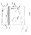
- FIG. 1depicts the solids flow control system for a moving bed heat exchanger that comprises a plurality of solids flow control valves
- FIG. 2is an enlarged depiction of the solids control flow valve showing the direction of flow of hot solids and/or ash;
- FIG. 3is a depiction of an orifice plate
- FIG. 4depicts the arrangement of the orifices in the successive plates with respect to the openings in the floor of the moving bed heat exchanger
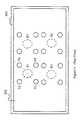
- FIG. 5shows only the arrangement of the orifices in the successive plates with respect to each other
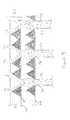
- FIG. 6is a depiction of an orifice plate that comprises a plurality of plates each of which comprise a plurality of hoppers with orifices;
- FIG. 7is a photograph of a slice model of a moving bed heat exchanger that does not have an orifice plate.
- FIG. 8is a photograph of a slice model of a moving bed heat exchanger that has an orifice plate.
- an orifice platefor use in a moving bed heat exchanger solids flow control system that controls the flow of high temperature solids (also know as high temperature ash) as they exit a moving bed heat exchanger and are transported to a combustion chamber, a reactor or receiving hopper.
- the orifice platecan also be used in other solids transfer devices where solids are to be transported.
- the orifice platecan also be used in other solids transfer devices where irregularly shaped solids are to be transported. For example, it can be used in the delivery system for smelting operations, where metal ores (e.g., bauxites, ferrites, and the like) are transported to a furnace for smelting.
- the solids flow control systemcontrols the flow of high temperature solids as they exit the moving bed heat exchanger, which in turn leads to control of the flow of solids within the moving bed heat exchanger.
- the solidsare hot solids and/or ash from the moving bed heat exchanger.
- the solids flow control systemcomprises the orifice plate for uniform distribution of solids throughout the moving bed heat exchanger.
- the orifice plateis disposed between the moving bed heat exchanger tube bundles and a solids flow control valve system.
- the solids flow valve systemadvantageously has no moving parts, which minimizes maintenance and improves reliability. It uses only an air pressure of up to about 4 pounds per square inch to facilitate transportation of solids back to a combustor or receiving hopper.
- the lack of moving parts in the solids flow control systemmakes the entire system easy to construct and to maintain.
- FIGS. 1 and 2depict the solids flow control system 100 for a moving bed heat exchanger 200 that comprises a plurality of valves 102 , 104 .
- Each valve 102 , 104comprises a standpipe 112 , a shoe 126 , and a housing 116 .
- hot solids and/or ash from the moving bed heat exchanger 200travels from the moving bed heat exchanger through the valve 102 into a transport conduit 120 to a combustor (not shown).
- the hot solids and/or ashtravels from the moving bed heat exchanger 200 through the standpipe 112 , the shoe 126 and the housing 116 before entering the transport conduit 120 from which they are transported to the combustion chamber 976 or to a reactor (not shown) or a transportation hopper (hot shown).
- the solids flow control system 100is disposed downstream of the moving bed heat exchanger 200 and in operative communication with it.
- the solids flow control system 100is generally located upstream of the combustion chamber 976 or the reactor or the hopper.
- the solids flow control system 100is disposed directly below the moving bed heat exchanger 200 and contacts an opening 210 in the floor or the moving bed heat exchanger.
- the moving bed heat exchanger 200comprises an enclosure 202 that contains a number of tubes.
- the tubesare termed heat exchanger tube bundles 220 .
- the enclosure 202is formed by vertical walls 204 of the moving bed heat exchanger, a roof 206 that contacts the vertical walls and a floor 208 that also contacts the vertical walls 204 .
- the moving bed heat exchangerreceives hot solids and/or ashes from the circulating fluidized bed boiler cyclone loop seal or from the combustor.
- the tubes (of the tube bundle 220 ) in the moving bed heat exchanger 200are arranged in one or more tube bundles, each having a multiplicity of tubes and arrangements.
- the cooling mediumis generally water, thermal coolant, or steam.
- the heating or cooling mediumflows through the tubes.
- Cooling medium and producte.g., hot solids and/or ash
- the coolerswork according to the moving bed principle, i.e., the hot solids and/or ash forms a product column which flows continuously downwards between the cooling pipes. Heat is transferred from the hot solids and/or ash through the tube walls to the cooling medium.
- the orifice plate 302is disposed proximate to the floor 208 of the moving bed heat exchanger between the solids flow control system 100 and the moving bed heat exchanger tube bundles 220 .
- the orifice plate 302lies downstream of a tube bundle (not shown) of the moving bed heat exchanger and upstream of the solids flow control system 100 . While the orifice plate 302 is depicted by solid lines in the FIGS. 1 and 2 , each orifice plate comprises a plurality of orifices. The arrangement of these orifices within each of the plates and the arrangement of the orifice plates will be described in detail below.
- the orifice plate 302regulates distribution of the hot solids and/or the ash in the moving bed heat exchanger as they flow downwards towards the floor 208 of the moving bed heat exchanger 200 and towards the solids flow control valve system 100 .
- the orifice plate 302is disposed across the entire cross-sectional area of the moving bed heat exchanger 200 and in one embodiment, may be parallel to the floor 208 of the heat exchanger 200 . In another embodiment, the orifice plate 302 may not be parallel to the floor 208 of the heat exchanger 200 .
- the orifice plate 302comprises one or more plates each of which contact the side walls of the moving bed heat exchanger 200 . In an exemplary embodiment, the orifice plate 302 is parallel to the floor 208 of the heat exchanger 200 .
- the orifice plate 302comprise one or more plates each of which has a plurality of holes through which the solids discharged from the moving bed heat exchanger tube bundle can travel uniformly to the ash control valves below the moving bed heat exchanger and from the moving bed heat exchanger to the combustor.
- the orifice platecomprise a plurality of plates, each plate of which has fewer holes of larger diameter than that of the plate above.
- the total cross-sectional area of the orifices (i.e., the sum of the cross-sectional area of the orifices) in the successive platesis generally equal to one another.
- FIG. 3depicts one embodiment of the orifice plate 302 .
- the orifice plate 302comprises a plurality of plates 304 , 306 , 308 and so on. While the orifice plate 302 in the FIG. 3 comprises 3 plates, it can comprise 1 to about 10 plates, and specifically about 2 to about 6 plates. In an exemplary embodiment, the orifice plate comprises about 2 plates.
- the orifice plate 302comprises three plates 304 , 306 , and 308 , where the plate 304 is disposed beneath the plate 306 , which is disposed beneath the plate 308 .
- Each platecomprises a sheet of metal having orifices disposed therein.
- the orificespermit solids to pass through.
- the orificespermits hot solids and/or ashes to pass from the moving bed heat exchanger to an ash flow control valve.
- the plate 304is referred to herein as the first plate or the lowest plate.
- the plate 306is referred to as the second plate or the second lowest plate, while the plate 308 is referred to as the third plate of the third lowest plate.
- Each successive plate from bottom to topcontains a larger number of orifices.
- the plate 304has fewer orifices than the plate 306 , which has fewer orifices than the plate 308 .
- the lowest plate 304generally has the same number of orifices as the number of valves 102 , 104 . For example, if the lowest plate 304 has 4 orifices, then the number of valves in the flow control system will also be 4.
- the number of orifices in the lowest plate 304is the same as the number of openings 210 in the floor 208 of the moving bed heat exchanger 200 .
- Each flow control valvecan be considered as the final in a series of plates that constitute the orifice plate 302 , with the number of valves equaling the number of orifices in the lowest plate.
- the floor 208 of the moving bed heat exchanger 200is not considered to be a part of the orifice plate 302 .
- the first plate or the lowest plate 304has a larger number of orifices than the number of openings 210 in the floor 208 of the moving bed heat exchanger 200 .
- the floor 208 of the moving bed heat exchanger 200is not considered to be a part of the orifice plate 302 .
- each successive plate (from bottom to top) in the orifice platecontains an increasing number of orifices that is dictated by the terms of a geometric sequence.
- each successive platewill contain a number of orifices dictated by a geometric sequence as follows:
- the second lowest platewill contain 4 orifices, while the third lowest plate will contain 8 orifices.
- “a”is equal to 1 and “r” is equal to 2.
- the second lowest platewill contain 16 orifices, while the third lowest plate will contain 64 orifices. In this case, “a” is equal to 1, and “r” is equal to 4. While the aforementioned embodiment teaches that the number of orifices may be increased according to a geometric sequence from the lowest plate to the uppermost plate, other sequences may be used so long as the number of orifices increases from the lowest plate to the uppermost plate.
- the diameter of each orificeis at least 3 times the maximum debri size, specifically at least 4 times the maximum debri size, and more specifically at least 5 times the maximum debri size that can cause blockage in the orifices or in the respective shoes 126 that are disposed downstream of the orifices.
- the diameteris about 3 centimeters to about 16 centimeters. In another embodiment, the diameter is about 6 centimeters to about 8 centimeters.
- the spacing between neighboring orifices in the lowest plate 304is determined by the orifice size and the ash or solids angle of repose. In another embodiment, the spacing between neighboring orifices in the lowest plate 304 is about 8 to about 20 centimeters.
- FIGS. 4 and 5depict an arrangement of the orifices in the successive plates 304 and 306 with respect to each other.
- FIG. 4represents a side view of the orifice plate 302
- FIG. 5represents a top view of the orifice plates.
- FIG. 4 and FIG. 5are not depictions of each other. In other words, the FIG. 4 is not a side view of the FIG. 5 and vice-versa.
- the FIG. 4depicts an arrangement of the orifices in the successive plates 304 and 306 with respect to the openings 210 in the floor 208 of the moving bed heat exchanger 200 .
- the FIG. 5shows only the arrangement of the orifices in the successive plates 304 and 306 with respect to each other.
- the lowest plate 304has fewer orifices than the second to lowest plate 306 .
- the total area of the orifices in the lowest plate 304is however about equal to the total area of the orifices in the second to lowest plate 306 .
- the orifices in the lower plateare coaxial with the openings 210 in the floor 208 of the moving bed heat exchanger, which are in turn coaxial with the standpipe 112 of the shoe 126 .
- the cross-sectional area of the individual orifices in the lowest plate 304are larger than the cross-sectional area of the individual orifices in the second to lowest plate 306 .
- the total area of the orifices in the lowest plate 304is therefore greater than or about equal to the total area of the orifices in the second to lowest plate 306 .
- the total area of the orifices in the plate 304may be less than the area of the orifices in the plate 306 , but this would restrict particle flow through the heat exchanger.
- the center of each orifice in the lowest plate 304is coaxial with a vertical line that represents the geometric center (the center of gravity or the center of rotation) of a plurality of orifices in the second to lowest plate 306 .
- the FIG. 5depicts this feature more clearly.
- the FIG. 5represents a top view taken from above the second to lowest plate 306 towards the lowest plate 304 .
- the FIG. 5depicts a portion of the second to lowest plate 306 that overlaps with a portion of the lowest plate 304 .
- the lowest plate 304has 4 orifices (B 1 , B 2 , B 3 and B 4 ) (represented by dashed lines), while the second to lowest plate 306 has 16 orifices (represented by solid lines).
- Four of these orifices A 1 , A 2 , A 3 and A 4 of the second to lowest plate 306discharge the hot solids and/or ashes to the orifice B 1 of the lowest plate 304 .
- Each orifice of the lowest plate 304has a center that is coaxial with the geometric center of the 4 orifices that lie in the second to lowest plate 306 proximate to that particular orifice.
- each orifice of the lowest plate 304has a center that is coaxial with the geometric center of the plurality of orifices (e.g., A 1 , A 2 , A 3 and A 4 ) that lie in the second to lowest plate 306 proximate to that particular orifice (e.g., B 1 ).
- the orifices A 1 , A 2 , A 3 and A 4lie at the vertices of a square, other locations for the orifices can also be chosen.
- the orificesmay lie along the perimeter of a circle or along the vertices (or the perimeter) of a polygon (e.g., a pentagon, a hexagon, or the like). Other irregular geometries may be chosen for locating the orifices. It is also to be noted that while the orifices in one plate may lie along the vertices of a first type of geometry (e.g., a square), the orifices in another plate may lie along the vertices or the perimeter of a second type of geometry (e.g., a pentagon or a circle).
- a first type of geometrye.g., a square
- a second type of geometrye.g., a pentagon or a circle
- the entire flow from an orifice in an upper plateflows into an orifice in a lower plate (e.g., the lowest plate 304 ).
- this ratiocan be varied from 2:1 to 20:1 if desired.
- the individual orifices in the plates or in the hoppersmay have a variety of cross-sectional geometries such as square, circular, rectangular, pentagonal or hexagonal. Other irregular geometries may also be used.
- the cross-sectional geometrymay be circular.
- the hot solids and/or ashesare discharged from the moving bed heat exchanger 200 towards the floor 208 they travel through the orifices in the second to lowest plate 306 towards the lowest plate 304 .
- the angle of repose ( ⁇ ) of the piledetermines the dimensions of the cone of flowing hot solids and/or ash that piles upon on each of the orifice plates and on the floor 208 of the moving bed heat exchanger.
- the pile of matterhas an angle of repose ( ⁇ ) that is determined by the characteristics of the hot solids and/or the ash in the pile.
- ⁇angle of repose
- the pile of hot solids and/or ash formed adjacent to an orificeinitially serves as a guide to direct the subsequent stream hot solids/and or ash into the orifices or openings that are down stream of the first orifice encountered by the stream of hot solids and/or ash.
- the angle of repose of a granular materialis the steepest angle of descent or dip of the slope relative to the horizontal plane when material on the slope face is on the verge of sliding.
- the internal angle between the surface of the pile and the horizontal surfaceis known as the angle of repose and is related to the density, surface area and shapes of the particles, and the coefficient of friction of the material.
- Material with a low angle of reposeforms flatter piles than material with a high angle of repose.
- the angle of repose for dry fine ashis about 30 to about 35 degrees
- for wet fine ashis about 45 to about 90 degrees
- for fly ashis about 40 degrees.
- the angle of repose ( ⁇ ) of the pile of hot solids and/or ashthus determines the minimum height between plates and the spacing between orifices in a given plate.
- the distance (height) between successive plates 304 , 306 and 308is thus determined by the angle of repose of the pile of ash. If the angle of repose of a pile of hot solids and/or ashes is too large (e.g., 75 degrees or greater), it may prevent the smooth flow of hot solids and/or ashes through the orifice above the pile.
- the height between successive platesis greater than the height of a pile of hot solids and/or ashes.
- the plates of the orifice plateare manufactured from high alloy steel, refractory tiles, or a combination thereof.
- the orifice plate 302may be constructed of a plurality of truncated pyramidal hoppers in close proximity to each other as opposed to the flat surface of the orifice plate 302 .
- the plurality of truncated pyramidal hoppersmay be arranged in rows, one above the other, in much the same manner as the successive plates that form the orifice plate. This is depicted in the FIG. 6 .
- the FIG. 6depicts an orifice plate comprising the lowest plate 304 having a plurality of pyramidal hoppers and the second to lowest plate 306 also having a plurality of pyramidal hoppers though larger in number when compared with the lowest plate 304 .
- the number of hoppersincreases from the lowest plate 304 to the highest plate (which is furthest away from the floor 208 of the moving bed heat exchanger).
- the configuration and location of the hoppers and the size of the orifices in the hoppersfollows the same logic described above with respect to the FIGS. 4 and 5 .
- the height between the hoppers and the distance between the orifices of the hoppersis dictated by the angle of repose ( ⁇ ) of the pile hot solids and/or the ash.
- a moving bed heat exchanger with an associated flow control device that has an orifice platehas a number of advantages over a moving bed heat exchanger with an associated flow control device that has no orifice plate associated with it.
- the orifice plateprovides uniform solids flow through the moving bed heat exchanger. It significantly reduces the moving bed heat exchanger height dimensions as compared with comparative moving bed heat exchangers that use mass flow hoppers.
- the orifice platetherefore ensures uniform solids flow throughout a moving bed heat exchanger without the excessive height dimensions needed with mass flow hoppers.
- Mass flow hopperscan also be used to ensure uniform solids flow, although with an excessive height dimension.
- a moving bed heat exchanger and a flow control system with an orifice platethus uses fewer ash control valves as compared with a comparative moving bed heat exchanger and flow control system with no orifice plate.
- the orifice plateis exemplified by the following examples, which are meant to be exemplary and not limiting.
- This exampledepicts the difference in the size of the moving bed heat exchanger when an orifice plate is used and when they are not used.
- Preliminary layouts of the moving bed heat exchangerindicate that ash flow distribution and control are important to the design.
- the original moving bed heat exchanger designsused mass flow hoppers with 70 degrees angles to ensure uniform solids flow throughout the moving bed heat exchanger.
- the hoppersare mounted above the standpipe 112 in the FIG. 2 shown above. This approach required a very tall moving bed heat exchanger or a moving bed heat exchanger with an excessive number of hoppers and ash control valves at the moving bed heat exchanger bottom.
- Use of the successive plates having orificesreduced the clearance height between the moving bed heat exchanger tube bundles and the inlet to the ash control valves by one third.
- An orifice plate system having 2 plateswas therefore developed to reduce the height requirements.
- the height between the platesis about 29 centimeters.
- the number or orifices in the first plate (the lowest plate)was 4, while the number of orifices in the second plate (the second lowest plate or the upper plate) was 16.
- the multiple orifice plate designresulted in the use of hoppers with angles ( ⁇ ) of 30 degrees to 35 degrees (instead of 70 degrees), resulting in a 60 percent to 70 percent height reduction in the distributor. This may be seen in the FIG. 6 .
- This exampledepicts the difference in performance between a moving bed heat exchanger without an orifice plate and one with an orifice plate.
- Four ash control valves as depicted in the FIG. 1were installed in the flat floor region below the moving bed heat exchanger with the hope that the ash would distribute itself uniformly at some level above the inlet of the ash control valve representing an internal solids angle of friction of 70 degrees.
- an orifice platecomprising two plates (with orifices) were installed above the ash control valve inlets to provide a uniform ash flow distribution through the tube bundle of the moving bed heat exchanger while reducing the height of the moving bed heat exchanger and minimizing the number of ash control valves.
- first,” “second,” “third” etc.may be used herein to describe various elements, components, regions, layers and/or sections, these elements, components, regions, layers and/or sections should not be limited by these terms. These terms are only used to distinguish one element, component, region, layer or section from another element, component, region, layer or section. Thus, “a first element,” “component,” “region,” “layer” or “section” discussed below could be termed a second element, component, region, layer or section without departing from the teachings herein.
- relative termssuch as “lower” or “bottom” and “upper” or “top,” may be used herein to describe one element's relationship to another element as illustrated in the Figures. It will be understood that relative terms are intended to encompass different orientations of the device in addition to the orientation depicted in the Figures. For example, if the device in one of the figures is turned over, elements described as being on the “lower” side of other elements would then be oriented on “upper” sides of the other elements. The exemplary term “lower,” can therefore, encompasses both an orientation of “lower” and “upper,” depending on the particular orientation of the figure.
- Exemplary embodimentsare described herein with reference to cross section illustrations that are schematic illustrations of idealized embodiments. As such, variations from the shapes of the illustrations as a result, for example, of manufacturing techniques and/or tolerances, are to be expected. Thus, embodiments described herein should not be construed as limited to the particular shapes of regions as illustrated herein but are to include deviations in shapes that result, for example, from manufacturing. For example, a region illustrated or described as flat may, typically, have rough and/or nonlinear features. Moreover, sharp angles that are illustrated may be rounded. Thus, the regions illustrated in the figures are schematic in nature and their shapes are not intended to illustrate the precise shape of a region and are not intended to limit the scope of the present claims.
Landscapes
- Engineering & Computer Science (AREA)
- Mechanical Engineering (AREA)
- General Engineering & Computer Science (AREA)
- Physics & Mathematics (AREA)
- Thermal Sciences (AREA)
- Heat-Exchange Devices With Radiators And Conduit Assemblies (AREA)
- Gasification And Melting Of Waste (AREA)
- Devices And Processes Conducted In The Presence Of Fluids And Solid Particles (AREA)
Abstract
Description
- a, ar, ar2, ar3, ar4, . . . , where “a” is the scale factor and “r” is the common ratio.
Claims (13)
Priority Applications (9)
| Application Number | Priority Date | Filing Date | Title |
|---|---|---|---|
| US13/283,411US9557115B2 (en) | 2010-10-28 | 2011-10-27 | Orifice plate for controlling solids flow, methods of use thereof and articles comprising the same |
| ES11781930.0TES2619947T3 (en) | 2010-10-28 | 2011-10-28 | Mobile bed exchanger comprising a hole plate to control the flow of solids |
| EP11781930.0AEP2633254B1 (en) | 2010-10-28 | 2011-10-28 | Moving bed heat exchanger comprising an orifice plate for controlling solids flow |
| HRP20170434TTHRP20170434T1 (en) | 2010-10-28 | 2011-10-28 | MOVING THERMAL HEAT EXCHANGER CONTAINING MEASURING DAMAGE FOR SOLID FLOW CONTROL |
| PL11781930TPL2633254T3 (en) | 2010-10-28 | 2011-10-28 | Moving bed heat exchanger comprising an orifice plate for controlling solids flow |
| CN201180063313.6ACN103270382B (en) | 2010-10-28 | 2011-10-28 | Control the orifice plates of solid particle stream and using method and include the article of orifice plates |
| PCT/US2011/058258WO2012058523A1 (en) | 2010-10-28 | 2011-10-28 | Orifice plate for controlling solids flow, methods of use thereof and articles comprising the same |
| HUE11781930AHUE031234T2 (en) | 2010-10-28 | 2011-10-28 | Moving bed heat exchanger comprising an orifice plate for controlling solids flow |
| RS20170278ARS55792B1 (en) | 2010-10-28 | 2011-10-28 | Moving bed heat exchanger comprising an orifice plate for controlling solids flow |
Applications Claiming Priority (4)
| Application Number | Priority Date | Filing Date | Title |
|---|---|---|---|
| US40774110P | 2010-10-28 | 2010-10-28 | |
| US40770610P | 2010-10-28 | 2010-10-28 | |
| US40769410P | 2010-10-28 | 2010-10-28 | |
| US13/283,411US9557115B2 (en) | 2010-10-28 | 2011-10-27 | Orifice plate for controlling solids flow, methods of use thereof and articles comprising the same |
Publications (2)
| Publication Number | Publication Date |
|---|---|
| US20120111535A1 US20120111535A1 (en) | 2012-05-10 |
| US9557115B2true US9557115B2 (en) | 2017-01-31 |
Family
ID=44936554
Family Applications (1)
| Application Number | Title | Priority Date | Filing Date |
|---|---|---|---|
| US13/283,411Active2035-06-05US9557115B2 (en) | 2010-10-28 | 2011-10-27 | Orifice plate for controlling solids flow, methods of use thereof and articles comprising the same |
Country Status (9)
| Country | Link |
|---|---|
| US (1) | US9557115B2 (en) |
| EP (1) | EP2633254B1 (en) |
| CN (1) | CN103270382B (en) |
| ES (1) | ES2619947T3 (en) |
| HR (1) | HRP20170434T1 (en) |
| HU (1) | HUE031234T2 (en) |
| PL (1) | PL2633254T3 (en) |
| RS (1) | RS55792B1 (en) |
| WO (1) | WO2012058523A1 (en) |
Cited By (1)
| Publication number | Priority date | Publication date | Assignee | Title |
|---|---|---|---|---|
| US20150299591A1 (en)* | 2012-12-27 | 2015-10-22 | Mitsubishi Heavy Industries, Ltd. | Char removal pipe |
Families Citing this family (2)
| Publication number | Priority date | Publication date | Assignee | Title |
|---|---|---|---|---|
| FR3010178B1 (en)* | 2013-08-30 | 2018-11-09 | Centre National De La Recherche Scientifique | METHOD FOR DETERMINING ORIFICE CHARACTERISTICS TO BE MADE THROUGH A PLATE AND CORRESPONDING PROGRAM |
| US10443945B2 (en)* | 2014-03-12 | 2019-10-15 | Lennox Industries Inc. | Adjustable multi-pass heat exchanger |
Citations (71)
| Publication number | Priority date | Publication date | Assignee | Title |
|---|---|---|---|---|
| US2316814A (en) | 1940-03-08 | 1943-04-20 | Schemm Henry Ripley | Feeder |
| US2756981A (en) | 1953-02-27 | 1956-07-31 | Kloeckner Humboldt Deutz Ag | Installation for the heating of fine granular material, especially cement raw material |
| GB1102264A (en) | 1966-02-01 | 1968-02-07 | Buell Engineering Company Inc | Method of and apparatus for coding or heating particulate material |
| DE1401704A1 (en) | 1962-08-22 | 1968-10-24 | Siemens Ag | Heat exchanger |
| DE1920889A1 (en) | 1969-04-24 | 1970-11-19 | Siemens Ag | Particle heat-exchanger |
| US3563006A (en) | 1967-06-22 | 1971-02-16 | Buss Ag | Separating and cooling device for plastic granules |
| US3679271A (en) | 1969-11-19 | 1972-07-25 | Brunswick Corp | Support for a fluidized bed |
| US3932173A (en)* | 1972-09-27 | 1976-01-13 | Allmanna Svenska Elektriska Aktiebolaget | Inductially heated gas lift pump action method for melt reduction |
| US4084545A (en) | 1975-10-21 | 1978-04-18 | Battelle Development Corporation | Operating method |
| US4279207A (en)* | 1979-04-20 | 1981-07-21 | Wormser Engineering, Inc. | Fluid bed combustion |
| US4307773A (en)* | 1978-08-28 | 1981-12-29 | Smith Richard D | Fluid bed heat exchanger for contaminated gas |
| US4479353A (en) | 1979-10-31 | 1984-10-30 | The Babcock & Wilcox Company | Moving bed heat storage and recovery system |
| US4501599A (en) | 1981-12-04 | 1985-02-26 | Pennsylvania Engineering Corporation | Method and apparatus for cleaning waste gases from aluminum production facilities |
| US4624305A (en)* | 1981-02-25 | 1986-11-25 | Institut Francais Du Petrole | Heat exchanger with staggered perforated plates |
| US4659340A (en)* | 1985-06-24 | 1987-04-21 | Weaver Lloyd E | Pressurized downdraft gasifier |
| EP0226140A2 (en) | 1985-12-16 | 1987-06-24 | Steag Ag | Method and apparatus for the combustion of solid fuels in a circulating fluidized bed |
| US4683840A (en) | 1985-09-09 | 1987-08-04 | Framatome | Boiler with a circulating fluidized bed |
| US4687497A (en) | 1986-09-29 | 1987-08-18 | Mobil Oil Corporation | Solids-gas separator |
| US4777889A (en) | 1987-05-22 | 1988-10-18 | Smith Richard D | Fluidized bed mass burner for solid waste |
| US4869207A (en) | 1987-07-13 | 1989-09-26 | A. Ahlstrom Corporation | Circulating fluidized bed reactor |
| US4909676A (en) | 1987-05-05 | 1990-03-20 | Waeschle Maschinenfabrik Gmbh | Apparatus for pneumatically conveying bulk material |
| CN1042412A (en) | 1988-10-31 | 1990-05-23 | 东南大学 | Normal pressure boiling furnace high-temperature ash cooler |
| US4955295A (en) | 1989-08-18 | 1990-09-11 | Foster Wheeler Energy Corporation | Method and system for controlling the backflow sealing efficiency and recycle rate in fluidized bed reactors |
| US4969930A (en) | 1989-02-22 | 1990-11-13 | A. Ahlstrom Corporation | Process for gasifying or combusting solid carbonaceous material |
| US5133943A (en) | 1990-03-28 | 1992-07-28 | Foster Wheeler Energy Corporation | Fluidized bed combustion system and method having a multicompartment external recycle heat exchanger |
| EP0543100A1 (en) | 1991-11-16 | 1993-05-26 | Deutsche Babcock Energie- und Umwelttechnik Aktiengesellschaft | Process and device for the removal of solid material |
| US5275788A (en) | 1988-11-11 | 1994-01-04 | Peter Stoholm | Circulating fluidized bed reactor |
| US5339774A (en) | 1993-07-06 | 1994-08-23 | Foster Wheeler Energy Corporation | Fluidized bed steam generation system and method of using recycled flue gases to assist in passing loopseal solids |
| US5441406A (en) | 1993-09-13 | 1995-08-15 | Dorr-Oliver Incorporated | Firing liquid and gaseous fuels for a circulating fluidizing bed reactor |
| US5676281A (en) | 1994-03-28 | 1997-10-14 | Bhm Company | Fluid flow airlock valve |
| US5682828A (en) | 1995-05-04 | 1997-11-04 | Foster Wheeler Energy Corporation | Fluidized bed combustion system and a pressure seal valve utilized therein |
| DE19629289A1 (en) | 1996-07-19 | 1998-01-22 | Umsicht Inst Fuer Umwelt Siche | Siphon for conveying fine particulate solid materials |
| US5711233A (en) | 1995-03-09 | 1998-01-27 | Martin Gmbh Fuer Umwelt- Und Energietechnik | Process and arrangement for the treatment of solid combustion residues in a combustion installation, in particular in a waste incineration plant |
| DE19723159A1 (en) | 1997-06-03 | 1998-12-10 | Siamant Ceramic Systems Gmbh & | Maximum temperature heat exchanger based on Siamant |
| US6076596A (en)* | 1996-03-14 | 2000-06-20 | Denso Corporation | Cooling apparatus for high-temperature medium by boiling and condensing refrigerant |
| US6269778B1 (en) | 1999-12-17 | 2001-08-07 | The Babcock & Wilcox Company | Fine solids recycle in a circulating fluidized bed |
| US6293112B1 (en)* | 1999-12-17 | 2001-09-25 | American Standard International Inc. | Falling film evaporator for a vapor compression refrigeration chiller |
| US6357517B1 (en)* | 1994-07-04 | 2002-03-19 | Denso Corporation | Cooling apparatus boiling and condensing refrigerant |
| US20020084059A1 (en)* | 2000-12-14 | 2002-07-04 | Herbert Rittberger | Heat exchanger |
| US6418866B1 (en) | 1998-06-16 | 2002-07-16 | Mitsubishi Heavy Industries, Ltd. | Operating method of fluidized-bed incinerator and the incinerator |
| US6457425B1 (en) | 1999-11-02 | 2002-10-01 | Consolidated Engineering Company, Inc. | Method and apparatus for combustion of residual carbon in fly ash |
| US20020192039A1 (en) | 2001-06-18 | 2002-12-19 | Pfeiffer John W. | System for handling bulk particulate materials |
| US20030019612A1 (en)* | 1996-03-14 | 2003-01-30 | Hiroyuki Osakabe | Cooling apparatus boiling and condensing refrigerant |
| US20030037730A1 (en)* | 1999-03-11 | 2003-02-27 | Tokyo Electron Limited | Processing system, evacuating system for processing system, low-pressure CVD system, and evacuating system and trapping device for low-pressure CVD system |
| US20030079863A1 (en)* | 2001-09-14 | 2003-05-01 | Hajime Sugito | Cooling apparatus boiling and condensing refrigerant with improved tunnel structure |
| US6589778B1 (en)* | 1999-12-15 | 2003-07-08 | Amersham Biosciences Ab | Method and apparatus for performing biological reactions on a substrate surface |
| US6684917B2 (en) | 2001-12-17 | 2004-02-03 | The University Of Western Ontario | Apparatus for volumetric metering of small quantity of powder from fluidized beds |
| US20040037658A1 (en) | 2002-08-20 | 2004-02-26 | Pfeiffer John W. | System for pneumatically conveying bulk particulate materials |
| US6764253B1 (en) | 2003-02-14 | 2004-07-20 | The Young Industries, Inc. | System and method for assuring fluidization of a material transported in a pneumatic conveying system |
| US6868695B1 (en)* | 2004-04-13 | 2005-03-22 | American Standard International Inc. | Flow distributor and baffle system for a falling film evaporator |
| US20050064357A1 (en) | 2001-11-12 | 2005-03-24 | Ishikawajima-Harima Heavy Industries Co., Ltd. | Circulating fluidized bed boiler |
| US20050155749A1 (en)* | 2004-01-20 | 2005-07-21 | Memory Stephen B. | Brazed plate high pressure heat exchanger |
| US6923128B2 (en) | 2003-01-10 | 2005-08-02 | Alstom Power Boiler Gmbh | Circulating fluidized bed reactor |
| US20050205015A1 (en)* | 2004-03-19 | 2005-09-22 | Atsushi Sasaki | Insulating film forming method, insulating film forming apparatus, and plasma film forming apparatus |
| US20060154190A1 (en)* | 2004-12-29 | 2006-07-13 | Reiser Carl A | Catalytic combustors keeping contained medium warm in response to hydrostatic valve |
| US7194983B2 (en) | 2004-07-01 | 2007-03-27 | Kvaerner Power Oy | Circulating fluidized bed boiler |
| EP1816095A1 (en) | 2006-02-07 | 2007-08-08 | IBAU Hamburg Ingenieurgesellschaft | Device for pneumatically conveying pulverulent material |
| US20080031697A1 (en) | 2004-12-17 | 2008-02-07 | Berggren Wouter D | Pipe Part For Conveying A Solid Particulate Material |
| US20080029001A1 (en)* | 2004-06-28 | 2008-02-07 | Taikisha Ltd | Thermal Storage Type Gas Treating Apparatus |
| US20080202735A1 (en)* | 2005-07-19 | 2008-08-28 | Peter Geskes | Heat Exchanger |
| US7448831B2 (en) | 2003-07-18 | 2008-11-11 | Linertech Limited | Fluidising mat, container and container liner with such a mat |
| US20090151902A1 (en) | 2007-12-12 | 2009-06-18 | Jacobs Robert V | Moving bed heat exchanger for circulating fluidized bed boiler |
| US7553111B2 (en) | 2007-06-28 | 2009-06-30 | Flsmidth A/S | Fluidizing gravity conveyor with high temperature multi-layered fluid distributor member |
| US20090304465A1 (en) | 2008-06-09 | 2009-12-10 | Greenwood Arthur R | L-Valve Construction for Controlling Solids Flow in a Liquid Medium Using Standard Pipe Fittings |
| CN101641462A (en) | 2007-03-22 | 2010-02-03 | 阿尔斯托姆科技有限公司 | Flue gas cooling and cleaning system |
| CN101754918A (en) | 2007-07-19 | 2010-06-23 | 艾尔坎国际有限公司 | Method for transporting powder material without segregation |
| US7937943B2 (en)* | 2006-12-22 | 2011-05-10 | Yiding Cao | Heat engines |
| US20110315350A1 (en)* | 2009-03-03 | 2011-12-29 | Harold Dean Curtis | Direct forced draft fluid cooler/cooling tower and liquid collector therefor |
| US8225936B2 (en) | 2007-02-27 | 2012-07-24 | Outotec Oyj | Method and apparatus for dividing a stream of solids |
| US20130174783A1 (en)* | 2010-07-12 | 2013-07-11 | Ulvac, Inc. | Film-forming apparatus |
| US20130336860A1 (en)* | 2011-02-18 | 2013-12-19 | Alstom Technology Ltd | Wet scrubber for cleaning an effluent gas |
Family Cites Families (1)
| Publication number | Priority date | Publication date | Assignee | Title |
|---|---|---|---|---|
| DE1920889U (en)* | 1965-05-06 | 1965-08-05 | Lothar J Tueffers | ELECTRONIC ORGAN IN COMBINATION WITH OTHER SOUND DEVICES. |
- 2011
- 2011-10-27USUS13/283,411patent/US9557115B2/enactiveActive
- 2011-10-28HUHUE11781930Apatent/HUE031234T2/enunknown
- 2011-10-28HRHRP20170434TTpatent/HRP20170434T1/enunknown
- 2011-10-28RSRS20170278Apatent/RS55792B1/enunknown
- 2011-10-28CNCN201180063313.6Apatent/CN103270382B/enactiveActive
- 2011-10-28ESES11781930.0Tpatent/ES2619947T3/enactiveActive
- 2011-10-28WOPCT/US2011/058258patent/WO2012058523A1/enactiveApplication Filing
- 2011-10-28PLPL11781930Tpatent/PL2633254T3/enunknown
- 2011-10-28EPEP11781930.0Apatent/EP2633254B1/enactiveActive
Patent Citations (76)
| Publication number | Priority date | Publication date | Assignee | Title |
|---|---|---|---|---|
| US2316814A (en) | 1940-03-08 | 1943-04-20 | Schemm Henry Ripley | Feeder |
| US2756981A (en) | 1953-02-27 | 1956-07-31 | Kloeckner Humboldt Deutz Ag | Installation for the heating of fine granular material, especially cement raw material |
| DE1401704A1 (en) | 1962-08-22 | 1968-10-24 | Siemens Ag | Heat exchanger |
| GB1102264A (en) | 1966-02-01 | 1968-02-07 | Buell Engineering Company Inc | Method of and apparatus for coding or heating particulate material |
| US3563006A (en) | 1967-06-22 | 1971-02-16 | Buss Ag | Separating and cooling device for plastic granules |
| DE1920889A1 (en) | 1969-04-24 | 1970-11-19 | Siemens Ag | Particle heat-exchanger |
| US3679271A (en) | 1969-11-19 | 1972-07-25 | Brunswick Corp | Support for a fluidized bed |
| US3932173A (en)* | 1972-09-27 | 1976-01-13 | Allmanna Svenska Elektriska Aktiebolaget | Inductially heated gas lift pump action method for melt reduction |
| US4084545A (en) | 1975-10-21 | 1978-04-18 | Battelle Development Corporation | Operating method |
| US4307773A (en)* | 1978-08-28 | 1981-12-29 | Smith Richard D | Fluid bed heat exchanger for contaminated gas |
| US4279207A (en)* | 1979-04-20 | 1981-07-21 | Wormser Engineering, Inc. | Fluid bed combustion |
| US4479353A (en) | 1979-10-31 | 1984-10-30 | The Babcock & Wilcox Company | Moving bed heat storage and recovery system |
| US4624305A (en)* | 1981-02-25 | 1986-11-25 | Institut Francais Du Petrole | Heat exchanger with staggered perforated plates |
| US4501599A (en) | 1981-12-04 | 1985-02-26 | Pennsylvania Engineering Corporation | Method and apparatus for cleaning waste gases from aluminum production facilities |
| US4659340A (en)* | 1985-06-24 | 1987-04-21 | Weaver Lloyd E | Pressurized downdraft gasifier |
| US4683840A (en) | 1985-09-09 | 1987-08-04 | Framatome | Boiler with a circulating fluidized bed |
| EP0226140A2 (en) | 1985-12-16 | 1987-06-24 | Steag Ag | Method and apparatus for the combustion of solid fuels in a circulating fluidized bed |
| US4687497A (en) | 1986-09-29 | 1987-08-18 | Mobil Oil Corporation | Solids-gas separator |
| US4909676A (en) | 1987-05-05 | 1990-03-20 | Waeschle Maschinenfabrik Gmbh | Apparatus for pneumatically conveying bulk material |
| US4777889A (en) | 1987-05-22 | 1988-10-18 | Smith Richard D | Fluidized bed mass burner for solid waste |
| US4869207A (en) | 1987-07-13 | 1989-09-26 | A. Ahlstrom Corporation | Circulating fluidized bed reactor |
| CN1042412A (en) | 1988-10-31 | 1990-05-23 | 东南大学 | Normal pressure boiling furnace high-temperature ash cooler |
| US5275788A (en) | 1988-11-11 | 1994-01-04 | Peter Stoholm | Circulating fluidized bed reactor |
| US4969930A (en) | 1989-02-22 | 1990-11-13 | A. Ahlstrom Corporation | Process for gasifying or combusting solid carbonaceous material |
| US4955295A (en) | 1989-08-18 | 1990-09-11 | Foster Wheeler Energy Corporation | Method and system for controlling the backflow sealing efficiency and recycle rate in fluidized bed reactors |
| US5133943A (en) | 1990-03-28 | 1992-07-28 | Foster Wheeler Energy Corporation | Fluidized bed combustion system and method having a multicompartment external recycle heat exchanger |
| EP0543100A1 (en) | 1991-11-16 | 1993-05-26 | Deutsche Babcock Energie- und Umwelttechnik Aktiengesellschaft | Process and device for the removal of solid material |
| US5339774A (en) | 1993-07-06 | 1994-08-23 | Foster Wheeler Energy Corporation | Fluidized bed steam generation system and method of using recycled flue gases to assist in passing loopseal solids |
| US5441406A (en) | 1993-09-13 | 1995-08-15 | Dorr-Oliver Incorporated | Firing liquid and gaseous fuels for a circulating fluidizing bed reactor |
| US5676281A (en) | 1994-03-28 | 1997-10-14 | Bhm Company | Fluid flow airlock valve |
| US6357517B1 (en)* | 1994-07-04 | 2002-03-19 | Denso Corporation | Cooling apparatus boiling and condensing refrigerant |
| US5711233A (en) | 1995-03-09 | 1998-01-27 | Martin Gmbh Fuer Umwelt- Und Energietechnik | Process and arrangement for the treatment of solid combustion residues in a combustion installation, in particular in a waste incineration plant |
| US5682828A (en) | 1995-05-04 | 1997-11-04 | Foster Wheeler Energy Corporation | Fluidized bed combustion system and a pressure seal valve utilized therein |
| US6076596A (en)* | 1996-03-14 | 2000-06-20 | Denso Corporation | Cooling apparatus for high-temperature medium by boiling and condensing refrigerant |
| US20030019612A1 (en)* | 1996-03-14 | 2003-01-30 | Hiroyuki Osakabe | Cooling apparatus boiling and condensing refrigerant |
| DE19629289A1 (en) | 1996-07-19 | 1998-01-22 | Umsicht Inst Fuer Umwelt Siche | Siphon for conveying fine particulate solid materials |
| DE19723159A1 (en) | 1997-06-03 | 1998-12-10 | Siamant Ceramic Systems Gmbh & | Maximum temperature heat exchanger based on Siamant |
| US6418866B1 (en) | 1998-06-16 | 2002-07-16 | Mitsubishi Heavy Industries, Ltd. | Operating method of fluidized-bed incinerator and the incinerator |
| US20030037730A1 (en)* | 1999-03-11 | 2003-02-27 | Tokyo Electron Limited | Processing system, evacuating system for processing system, low-pressure CVD system, and evacuating system and trapping device for low-pressure CVD system |
| US6457425B1 (en) | 1999-11-02 | 2002-10-01 | Consolidated Engineering Company, Inc. | Method and apparatus for combustion of residual carbon in fly ash |
| US6589778B1 (en)* | 1999-12-15 | 2003-07-08 | Amersham Biosciences Ab | Method and apparatus for performing biological reactions on a substrate surface |
| US6293112B1 (en)* | 1999-12-17 | 2001-09-25 | American Standard International Inc. | Falling film evaporator for a vapor compression refrigeration chiller |
| US6269778B1 (en) | 1999-12-17 | 2001-08-07 | The Babcock & Wilcox Company | Fine solids recycle in a circulating fluidized bed |
| US20020084059A1 (en)* | 2000-12-14 | 2002-07-04 | Herbert Rittberger | Heat exchanger |
| US20020192039A1 (en) | 2001-06-18 | 2002-12-19 | Pfeiffer John W. | System for handling bulk particulate materials |
| US20030079863A1 (en)* | 2001-09-14 | 2003-05-01 | Hajime Sugito | Cooling apparatus boiling and condensing refrigerant with improved tunnel structure |
| US20050064357A1 (en) | 2001-11-12 | 2005-03-24 | Ishikawajima-Harima Heavy Industries Co., Ltd. | Circulating fluidized bed boiler |
| US6684917B2 (en) | 2001-12-17 | 2004-02-03 | The University Of Western Ontario | Apparatus for volumetric metering of small quantity of powder from fluidized beds |
| US20040037658A1 (en) | 2002-08-20 | 2004-02-26 | Pfeiffer John W. | System for pneumatically conveying bulk particulate materials |
| US6923128B2 (en) | 2003-01-10 | 2005-08-02 | Alstom Power Boiler Gmbh | Circulating fluidized bed reactor |
| CN1279312C (en) | 2003-01-10 | 2006-10-11 | 阿尔斯托姆动力锅炉有限公司 | Circulating Fluidized Bed Reactor |
| US6764253B1 (en) | 2003-02-14 | 2004-07-20 | The Young Industries, Inc. | System and method for assuring fluidization of a material transported in a pneumatic conveying system |
| US7448831B2 (en) | 2003-07-18 | 2008-11-11 | Linertech Limited | Fluidising mat, container and container liner with such a mat |
| US20050155749A1 (en)* | 2004-01-20 | 2005-07-21 | Memory Stephen B. | Brazed plate high pressure heat exchanger |
| US20050205015A1 (en)* | 2004-03-19 | 2005-09-22 | Atsushi Sasaki | Insulating film forming method, insulating film forming apparatus, and plasma film forming apparatus |
| US6868695B1 (en)* | 2004-04-13 | 2005-03-22 | American Standard International Inc. | Flow distributor and baffle system for a falling film evaporator |
| US20080029001A1 (en)* | 2004-06-28 | 2008-02-07 | Taikisha Ltd | Thermal Storage Type Gas Treating Apparatus |
| US7194983B2 (en) | 2004-07-01 | 2007-03-27 | Kvaerner Power Oy | Circulating fluidized bed boiler |
| US20080031697A1 (en) | 2004-12-17 | 2008-02-07 | Berggren Wouter D | Pipe Part For Conveying A Solid Particulate Material |
| US20060154190A1 (en)* | 2004-12-29 | 2006-07-13 | Reiser Carl A | Catalytic combustors keeping contained medium warm in response to hydrostatic valve |
| US20080202735A1 (en)* | 2005-07-19 | 2008-08-28 | Peter Geskes | Heat Exchanger |
| US20070183854A1 (en) | 2006-02-07 | 2007-08-09 | Ibau Hamburg Ingenieurgesellschaft Industriebau Mbh | Device for the pneumatic conveying of particulate and powdery bulk material |
| EP1816095A1 (en) | 2006-02-07 | 2007-08-08 | IBAU Hamburg Ingenieurgesellschaft | Device for pneumatically conveying pulverulent material |
| US7329071B2 (en) | 2006-02-07 | 2008-02-12 | Ibau Hamburg Ingenieurgesellschaft Industriebau Mbh | Device for the pneumatic conveying of particulate and powdery bulk material |
| US7937943B2 (en)* | 2006-12-22 | 2011-05-10 | Yiding Cao | Heat engines |
| US8225936B2 (en) | 2007-02-27 | 2012-07-24 | Outotec Oyj | Method and apparatus for dividing a stream of solids |
| CN101641462A (en) | 2007-03-22 | 2010-02-03 | 阿尔斯托姆科技有限公司 | Flue gas cooling and cleaning system |
| US20100101760A1 (en) | 2007-03-22 | 2010-04-29 | Geir Wedde | Flue gas cooling and cleaning system |
| US7553111B2 (en) | 2007-06-28 | 2009-06-30 | Flsmidth A/S | Fluidizing gravity conveyor with high temperature multi-layered fluid distributor member |
| US20100189518A1 (en) | 2007-07-19 | 2010-07-29 | Alcan International Limited | Process for conveying powder materials without segregation |
| CN101754918A (en) | 2007-07-19 | 2010-06-23 | 艾尔坎国际有限公司 | Method for transporting powder material without segregation |
| US20090151902A1 (en) | 2007-12-12 | 2009-06-18 | Jacobs Robert V | Moving bed heat exchanger for circulating fluidized bed boiler |
| US20090304465A1 (en) | 2008-06-09 | 2009-12-10 | Greenwood Arthur R | L-Valve Construction for Controlling Solids Flow in a Liquid Medium Using Standard Pipe Fittings |
| US20110315350A1 (en)* | 2009-03-03 | 2011-12-29 | Harold Dean Curtis | Direct forced draft fluid cooler/cooling tower and liquid collector therefor |
| US20130174783A1 (en)* | 2010-07-12 | 2013-07-11 | Ulvac, Inc. | Film-forming apparatus |
| US20130336860A1 (en)* | 2011-02-18 | 2013-12-19 | Alstom Technology Ltd | Wet scrubber for cleaning an effluent gas |
Non-Patent Citations (16)
| Title |
|---|
| European Office Action issued in connection with related EP Application No. 11781929.2 on Feb. 20, 2014. |
| Federal Highway Administration, "User Guidelines for Waste and Byproduct Materials in Pavement Construction", US Department of Transportation, Publication No. FHWA-RD-97-148, Nov. 2014. |
| Final Office Action issued in connection with related U.S. Appl. No. 13/283,355 on Jul. 16, 2014. |
| Final Office Action issued in connection with related U.S. Appl. No. 13/283,355 on Sep. 11, 2015. |
| Final Office Action issued in connection with related U.S. Appl. No. 13/283,355 on Sep. 25, 2013. |
| Glen D. Jukkola et al., U.S. Appl. No. 61/407,706, filed Oct. 28, 2010. |
| Non-Final Office Action issued in connection with related U.S. Appl. No. 13/283,355 on Apr. 8, 2015. |
| Non-Final Office Action issued in connection with related U.S. Appl. No. 13/283,355 on Feb. 26, 2014. |
| Non-Final Office Action issued in connection with related U.S. Appl. No. 13/283,355 on Jun. 14, 2016. |
| Non-Final Office Action issued in connection with related U.S. Appl. No. 13/283,355 on Mar. 1, 2013. |
| Notice of Allowance issued from related U.S. Appl. No. 13/283,355 dated Dec. 7, 2016. |
| PCT Search Report and Written Opinion issued in connection with related PCT Application No. PCT/US2011/058245 on Feb. 6, 2012. |
| State Intellectual Property Office of People's Republic of China-Office Action dated Aug. 15, 2014 for CN Appln. No. 201180063313.6. |
| Unofficial English translation of Chinese Office Action and Search Report issued in connection with related CN Application No. 201180063296.6 on Apr. 30, 2014. |
| US Advisory Action issued in connection with related U.S. Appl. No. 13/283,355 on Oct. 9, 2014. |
| Zenz et al., "Fluidization and Fluid-Particle Systems", Reinhold Chemical Engineering Series, Reinhold, NY, 50 pages, 1960. |
Cited By (2)
| Publication number | Priority date | Publication date | Assignee | Title |
|---|---|---|---|---|
| US20150299591A1 (en)* | 2012-12-27 | 2015-10-22 | Mitsubishi Heavy Industries, Ltd. | Char removal pipe |
| US9834733B2 (en)* | 2012-12-27 | 2017-12-05 | Mitsubishi Heavy Industries, Ltd. | Char removal pipe |
Also Published As
| Publication number | Publication date |
|---|---|
| WO2012058523A1 (en) | 2012-05-03 |
| RS55792B1 (en) | 2017-08-31 |
| HUE031234T2 (en) | 2018-06-28 |
| ES2619947T3 (en) | 2017-06-27 |
| PL2633254T3 (en) | 2017-05-31 |
| EP2633254B1 (en) | 2016-12-28 |
| HRP20170434T1 (en) | 2017-05-19 |
| CN103270382B (en) | 2016-08-10 |
| US20120111535A1 (en) | 2012-05-10 |
| EP2633254A1 (en) | 2013-09-04 |
| CN103270382A (en) | 2013-08-28 |
Similar Documents
| Publication | Publication Date | Title |
|---|---|---|
| CA1328345C (en) | Fluid-bed combustion reactor and a method for the operation of such fluid-bed combustion reactor | |
| PL178960B1 (en) | Circulating fluidized bed fuel reactor PL PL PL PL PL PL PL PL | |
| US20230175777A1 (en) | Device for producing supplementary cementitious material | |
| US9557115B2 (en) | Orifice plate for controlling solids flow, methods of use thereof and articles comprising the same | |
| CN212805617U (en) | Wall of material returning heat exchanger, material returning heat exchanger and circulating fluidized bed boiler | |
| CN102032558B (en) | Circulating fluidized bed (CFB) with in-furnace secondary air nozzles | |
| US9617087B2 (en) | Control valve and control valve system for controlling solids flow, methods of manufacture thereof and articles comprising the same | |
| CN118758067A (en) | A feeding device for grate cooler | |
| CN106029600B (en) | Flow calcining furnace | |
| CN108955275B (en) | Vertical sinter cooler with chute type distributor and sinter cooling method | |
| CN107401938B (en) | A kind of gas-particle two-phase heat exchange equipment | |
| CN101311626B (en) | Integral fluid bed ash cooler | |
| CN107677135B (en) | Counter-flow low-resistance cement clinker cooler | |
| US3315372A (en) | Apparatus for uniform distribution of pebbles in heat exchangers | |
| EP1847774B1 (en) | A fluidized bed boiler and a grate element for the same | |
| KR101744792B1 (en) | Circulating fluidized bed boiler | |
| US6389776B1 (en) | Gas permeable refractory brick for use in regenerative heat exchanger and hot grid formed therefrom | |
| CN111895390B (en) | Air distribution system of external heat exchanger of circulating fluidized bed boiler | |
| RU2224196C2 (en) | Fluidized bed furnace for roasting of limestone | |
| RU2752476C1 (en) | Catalytic reactor for the disposal of sediments from municipal wastewater treatment plants and a method for disposal | |
| KR20130074303A (en) | Fluidized bed combustor with terraced floor structure | |
| SU1081401A1 (en) | Apparatus for thermal treatment of grainy material | |
| CN118816194A (en) | A wear-resistant structure for circulating fluidized bed boiler | |
| JPS63131916A (en) | Fluidized bed type heat reaction equipment | |
| PL107724B1 (en) | FLUIDIZATION FURNACE WITH A DEVICE FOR HEAT DRAINAGE FROM THE SUSPENSION LAYER |
Legal Events
| Date | Code | Title | Description |
|---|---|---|---|
| AS | Assignment | Owner name:ALSTOM TECHNOLOGY LTD, SWITZERLAND Free format text:ASSIGNMENT OF ASSIGNORS INTEREST;ASSIGNORS:JUKKOLA, GLEN D.;TEIGEN, BARD C.;SIGNING DATES FROM 20101101 TO 20101102;REEL/FRAME:027549/0488 | |
| AS | Assignment | Owner name:GENERAL ELECTRIC TECHNOLOGY GMBH, SWITZERLAND Free format text:CHANGE OF NAME;ASSIGNOR:ALSTOM TECHNOLOGY LTD;REEL/FRAME:039714/0578 Effective date:20151102 | |
| STCF | Information on status: patent grant | Free format text:PATENTED CASE | |
| MAFP | Maintenance fee payment | Free format text:PAYMENT OF MAINTENANCE FEE, 4TH YEAR, LARGE ENTITY (ORIGINAL EVENT CODE: M1551); ENTITY STATUS OF PATENT OWNER: LARGE ENTITY Year of fee payment:4 | |
| AS | Assignment | Owner name:UNITED STATES DEPARTMENT OF ENERGY, DISTRICT OF COLUMBIA Free format text:CONFIRMATORY LICENSE;ASSIGNOR:GE STEAM POWER, INC.;REEL/FRAME:064013/0645 Effective date:20230203 | |
| MAFP | Maintenance fee payment | Free format text:PAYMENT OF MAINTENANCE FEE, 8TH YEAR, LARGE ENTITY (ORIGINAL EVENT CODE: M1552); ENTITY STATUS OF PATENT OWNER: LARGE ENTITY Year of fee payment:8 | |
| AS | Assignment | Owner name:POWER SOLUTIONS GAMMA FRANCE, FRANCE Free format text:NUNC PRO TUNC ASSIGNMENT;ASSIGNOR:GENERAL ELECTRIC TECHNOLOGY GMBH;REEL/FRAME:069450/0966 Effective date:20241122 Owner name:ARABELLE TECHNOLOGIES, FRANCE Free format text:CHANGE OF NAME;ASSIGNOR:POWER SOLUTIONS GAMMA FRANCE;REEL/FRAME:069451/0916 Effective date:20240531 | |
| AS | Assignment | Owner name:ARABELLE SOLUTIONS FRANCE, FRANCE Free format text:MERGER;ASSIGNOR:ARABELLE TECHNOLOGIES;REEL/FRAME:070587/0348 Effective date:20241203 |