US9557079B2 - System and method for storing thermal energy - Google Patents
System and method for storing thermal energyDownload PDFInfo
- Publication number
- US9557079B2 US9557079B2US13/183,266US201113183266AUS9557079B2US 9557079 B2US9557079 B2US 9557079B2US 201113183266 AUS201113183266 AUS 201113183266AUS 9557079 B2US9557079 B2US 9557079B2
- Authority
- US
- United States
- Prior art keywords
- water
- container
- thermal
- internal volume
- pipe
- Prior art date
- Legal status (The legal status is an assumption and is not a legal conclusion. Google has not performed a legal analysis and makes no representation as to the accuracy of the status listed.)
- Expired - Fee Related, expires
Links
Images


Classifications
- F—MECHANICAL ENGINEERING; LIGHTING; HEATING; WEAPONS; BLASTING
- F24—HEATING; RANGES; VENTILATING
- F24T—GEOTHERMAL COLLECTORS; GEOTHERMAL SYSTEMS
- F24T10/00—Geothermal collectors
- F24T10/30—Geothermal collectors using underground reservoirs for accumulating working fluids or intermediate fluids
- F—MECHANICAL ENGINEERING; LIGHTING; HEATING; WEAPONS; BLASTING
- F03—MACHINES OR ENGINES FOR LIQUIDS; WIND, SPRING, OR WEIGHT MOTORS; PRODUCING MECHANICAL POWER OR A REACTIVE PROPULSIVE THRUST, NOT OTHERWISE PROVIDED FOR
- F03G—SPRING, WEIGHT, INERTIA OR LIKE MOTORS; MECHANICAL-POWER PRODUCING DEVICES OR MECHANISMS, NOT OTHERWISE PROVIDED FOR OR USING ENERGY SOURCES NOT OTHERWISE PROVIDED FOR
- F03G7/00—Mechanical-power-producing mechanisms, not otherwise provided for or using energy sources not otherwise provided for
- F03G7/04—Mechanical-power-producing mechanisms, not otherwise provided for or using energy sources not otherwise provided for using pressure differences or thermal differences occurring in nature
- F03G7/05—Ocean thermal energy conversion, i.e. OTEC
- F24J3/086—
- Y—GENERAL TAGGING OF NEW TECHNOLOGICAL DEVELOPMENTS; GENERAL TAGGING OF CROSS-SECTIONAL TECHNOLOGIES SPANNING OVER SEVERAL SECTIONS OF THE IPC; TECHNICAL SUBJECTS COVERED BY FORMER USPC CROSS-REFERENCE ART COLLECTIONS [XRACs] AND DIGESTS
- Y02—TECHNOLOGIES OR APPLICATIONS FOR MITIGATION OR ADAPTATION AGAINST CLIMATE CHANGE
- Y02E—REDUCTION OF GREENHOUSE GAS [GHG] EMISSIONS, RELATED TO ENERGY GENERATION, TRANSMISSION OR DISTRIBUTION
- Y02E10/00—Energy generation through renewable energy sources
- Y02E10/10—Geothermal energy
- Y02E10/16—
- Y—GENERAL TAGGING OF NEW TECHNOLOGICAL DEVELOPMENTS; GENERAL TAGGING OF CROSS-SECTIONAL TECHNOLOGIES SPANNING OVER SEVERAL SECTIONS OF THE IPC; TECHNICAL SUBJECTS COVERED BY FORMER USPC CROSS-REFERENCE ART COLLECTIONS [XRACs] AND DIGESTS
- Y02—TECHNOLOGIES OR APPLICATIONS FOR MITIGATION OR ADAPTATION AGAINST CLIMATE CHANGE
- Y02E—REDUCTION OF GREENHOUSE GAS [GHG] EMISSIONS, RELATED TO ENERGY GENERATION, TRANSMISSION OR DISTRIBUTION
- Y02E10/00—Energy generation through renewable energy sources
- Y02E10/30—Energy from the sea, e.g. using wave energy or salinity gradient
- Y02E10/34—
- Y—GENERAL TAGGING OF NEW TECHNOLOGICAL DEVELOPMENTS; GENERAL TAGGING OF CROSS-SECTIONAL TECHNOLOGIES SPANNING OVER SEVERAL SECTIONS OF THE IPC; TECHNICAL SUBJECTS COVERED BY FORMER USPC CROSS-REFERENCE ART COLLECTIONS [XRACs] AND DIGESTS
- Y02—TECHNOLOGIES OR APPLICATIONS FOR MITIGATION OR ADAPTATION AGAINST CLIMATE CHANGE
- Y02E—REDUCTION OF GREENHOUSE GAS [GHG] EMISSIONS, RELATED TO ENERGY GENERATION, TRANSMISSION OR DISTRIBUTION
- Y02E60/00—Enabling technologies; Technologies with a potential or indirect contribution to GHG emissions mitigation
- Y02E60/14—Thermal energy storage
Definitions
- Embodiments of the inventionrelate generally to thermal energy storage and, more particularly, to a system and method of storing thermal energy in an underwater storage device.
- RE sourcesoffer an alternative to conventional power sources in an age of dwindling non-renewable energy sources and high carbon emissions.
- RE sourcesare often not fully exploited because many forms of renewable energy are not available when the peak demand is present.
- RE sourcesmay be most available during undesirable off-peak hours, or may be located in areas that are remote from population centers or locations where power is most needed, having to share the grid during peak hours along with all the other peak power sources.
- RE sourcesmay include hydro power, geothermal, Ocean Thermal Energy Conversion (OTEC), as examples.
- Hydro powerfor instance, when combined with a reservoir is one RE source that can be throttled up and down to match or load-follow the varying power loads.
- Geothermal and OTECare also good baseload RE resources; however, viable locations for geothermal and OTEC are limited.
- an ocean thermal energy converterwhile traditionally utilized across the thermocline of an ocean, can additionally apply to fresh bodies of water that have a temperature difference between surface water and deep water.
- RE sourcesmay also include solar, wind, wave, and tidal, as examples. However these sources tend to be intermittent in their ability to provide power. Energy storage is thus desired for those sources to substantially contribute to the grid energy supply.
- Cost-effective storage for the electrical gridhas been sought from the beginning of electrical service delivery but is not yet available.
- the variation in power demand throughout a day, and season-to-seasonrequires generation assets that are utilized only part of the time, which can increase capital, operations, and maintenance costs for assets used at less than full capacity.
- generation assetsare difficult to throttle or shut down and are difficult to quickly return to full power.
- Energy storagecan provide a buffer to better match power demand and supply allowing power sources to operate at higher capacity and thus higher efficiency.
- CAESCompressed air energy storage
- FIG. 1One approach for CAES is illustrated in FIG. 1 .
- CAES system 10includes an input power 12 which can be, for example, from a renewable energy source such as wind power, wave power (e.g., via a “Salter Duck”), current power, tidal power, or solar power, as examples.
- input power 12may be from an electrical power grid.
- a renewable energy (RE) sourcesuch a source may provide intermittent power.
- RErenewable energy
- system 10may be connected thereto and controlled in a fashion that electrical power may be drawn and stored as compressed fluid energy during off-peak hours such as during late evening or early morning hours, and then recovered during peak hours when energy drawn from system 10 may be sold at a premium (i.e., electrical energy arbitrage), or to augment base load power systems such as coal to provide peaking capability by storing inexpensive base load power.
- a premiumi.e., electrical energy arbitrage
- base load power systemssuch as coal to provide peaking capability by storing inexpensive base load power.
- Input power 12is coupled to mechanical power 14 to compress fluid from a fluid inlet 16 , and fluid compression 18 results. Cooling may be introduced via pumps and heat exchangers or through direct contact between the compressed fluid and a cooling fluid. Fluid from fluid compression 18 is conveyed to compressed fluid storage 20 via a fluid input 22 .
- compressed fluidmay be drawn from compressed fluid storage 20 via fluid output 24 , and fluid expansion 26 occurs, which results in available energy that may be conveyed to, for instance, a mechanical device that extracts mechanical power 28 for electrical power generation 30 .
- the generated electrical powermay be conveyed to a grid or other device where it is desirable to have electrical power delivered.
- Outlet fluid 32is expelled to the environment at generally standard or ambient pressure.
- system 10When operated close to isothermally (i.e., quasi-isothermally), system 10 includes forced-convection cooling 34 to cool the fluid from fluid compression 18 and forced-convection heating 36 to heat the fluid from fluid expansion 26 . Because compressed fluid storage occurs at generally ambient temperature and pressure, both cooling 34 for fluid compression 18 and heating 36 after fluid expansion 26 may be performed using the vast amount of environmental fluid that surrounds system 10 at ambient temperature and pressure.
- FIG. 2illustrates a marine-based, quasi-isothermal implementation of CAES system 10 .
- Components of system 10are positioned on a platform 38 proximately to the water surface of a sea 40 .
- Platform 38is supported by the seafloor 42 .
- a compressed air storage assembly 44is positioned at an average depth 46 , and a compressor/expander system (C/E) 48 is coupled to a generator 50 .
- C/E 48may include multiple stages of compression and expansion for quasi-isothermal operation, and a heat exchanger package (not shown in this figure) may cool or reheat the fluid between the stages of compression or expansion, respectively.
- a fluid hose or pipe, or pressurized-fluid conveyance system 52connects fluid storage bag assembly 44 with the C/E 48 at or near the surface of sea 40 .
- C/E 48operates to compress fluid, convey it to fluid storage tube assembly 44 via fluid hose or pipe 52 , and store the energy therein.
- Power 54may be provided via a renewable source such as wind, wave motion, tidal motion, or may be provided via the generator 50 operated as a motor which may draw energy from, for instance, a power grid.
- C/E 48may be operated in reverse by drawing compressed stored energy from fluid storage tube assembly 44 via fluid hose or pipe 52 to drive the generator 50 to generate AC or DC power.
- CAES system 10While operation of CAES system 10 in a marine-based quasi-isothermal operation takes advantage of the generation of energy from cost-effective sources, quasi-isothermal CAES systems typically compress fluid in a plurality of compression stages, and with cooling or heating within or between stages achieved via pumps and heat exchangers.
- An adiabatic CAES systemallows for storing thermal energy generated during fluid compression, which is not disposed of but used subsequently to preheat the compressed air prior to or during fluid expansion.
- thermal energyis stored at high temperatures that require expensive media and containment systems.
- one proposal for thermal storageincludes the use of thermal storage containers filled with stone or ceramic bricks, stored at 600° C.
- thermal storage containers filled with stone or ceramic bricksstored at 600° C.
- Such a high temperature systemis challenging and expensive to enclose and insulate.
- Wateron the other hand, has very high heat capacity, is very inexpensive, but is challenging to use as a storage medium because of its relatively low boiling point at low or moderate pressures.
- thermal energy storage systemsthat incorporate water or other low cost, non-toxic liquids as the energy storage medium.
- thermal energy storage systemscan be deployed both on land and offshore, or partly on land and partly offshore, it would be advantageous to have thermal energy storage systems which can incorporate low cost thermal storage in both environments.
- a thermal energy storage systemincludes a container positioned within a surrounding body of water and comprising a container wall.
- the wallhas an interior surface exposed to and defining an internal volume of the container and has an exterior surface opposite the interior surface and exposed to the surrounding body of water.
- the internal volumeis substantially full of water, and the container is configured to thermally separate water within the internal volume along the interior surface from water of the surrounding body of water along the exterior surface.
- a thermal source in thermal communication with the water within the internal volumeis configured to transfer a thermal potential to the water within the internal volume.
- a method of deploying a thermal energy storage systemincludes positioning a thermal storage container within a body of water.
- the thermal storage containerincludes a wall having a first surface facing a first volume positioned within an interior of the container and a second surface opposite from the first surface and facing the body of water.
- the methodalso includes thermally coupling a thermal source to an entrained volume of water substantially filling the first volume, the thermal source configured to transfer heat to the entrained volume of water.
- the wallis configured to impede a transfer of thermal energy therethrough from the body of water to the entrained volume of water.
- FIG. 1is a schematic diagram illustrating a compressed air energy storage (CAES) system.
- CAEScompressed air energy storage
- FIG. 2is a schematic diagram illustrating a CAES system FIG. 1 in a marine environment without thermal energy storage.
- FIG. 3is a schematic diagram illustrating an adiabatic operation of the system FIG. 1 in a marine environment according to an embodiment of the invention.
- FIG. 4is a schematic diagram illustrating a thermal storage vessel thermally coupled to a heat exchanger according to an embodiment of the invention.
- FIG. 5is a cross-sectional view of the thermal storage vessel of FIG. 4 according to another embodiment of the invention.
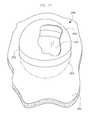
- FIG. 6is an exploded view of the thermal storage vessel of FIG. 4 according to an embodiment of the invention.
- FIG. 7is a schematic diagram illustrating a thermal storage vessel thermally coupled to a heat exchanger according to another embodiment of the invention.
- FIG. 8is a schematic diagram illustrating the thermal storage vessel of FIG. 7 thermally coupled to a heat exchanger according to another embodiment of the invention.
- FIG. 9is a view illustrating a multi-layer wall of a thermal storage vessel according to an embodiment of the invention.
- FIG. 10is a process flow diagram illustrating a multi-staged compression and expansion system according to an embodiment of the invention.
- FIG. 11is an isometric view of a thermal enclosure according to an embodiment of the invention.
- FIG. 12is a section view of a thermal enclosure according to another embodiment of the invention.
- FIG. 13is an isometric view of a thermal enclosure according to another embodiment of the invention.
- FIG. 14is an isometric view of a thermal enclosure according to another embodiment of the invention.
- Embodiments of the inventionincorporate a pressure-modifying device with multiple stages, operating with both adiabatic and quasi-isothermal elements.
- the deviceprovides several stages of compression to a gas, with the heat of compression being removed after each stage, thus managing the temperature rise in each stage. This heat of compression is then captured in a thermal energy store which can therefore be operated at relatively modest temperatures compared to a fully-adiabatic system with thermal storage.
- expansion phasethe same pressure-modifying device operating in reverse, or in other embodiments, a different pressure-modifying device, provides several stages of expansion to the previously compressed gas, with heat being added to the gas before each stage of expansion. In other embodiments heat may be extracted or added to the gas during each stage rather than between stages.
- the resulting temperature rise in each stagecan be kept to 76° C., and the temperature of the thermal storage medium can be kept to under 100° C., below the boiling point of water at 1 atm.
- Thisin conjunction with a thermal storage vessel comprising primarily thin films of inexpensive polymer and possibly earth or water that is already on site, can allow for a very low cost CAES system with thermal energy storage where the thermal storage medium in the thermal storage vessel is stored at relatively low pressure differences relative to ambient pressure.
- the thermal storage vesselis under water, or where the thermal storage vessel is a pressure vessel, it is possible to design the system with fewer stages and to use as the storage medium water at a higher temperature. For example, if the thermal storage vessel is at a depth of 90 meters, with roughly 10 atm of pressure, the maximum operating temperature may be as high as 180° C.
- Embodiments of the inventioninclude deployment or installation of a thermal energy storage vessel and a body of water such as an ocean, sea, lake, reservoir, gulf, harbor, inlet, river, or any other man-made or natural body of water.
- arefers to any such body of water
- floorrefers to the floor thereof
- Segmente.g., “seafloor sediment”
- gravelsand, silt, clay, mud, organic or other material settled onto the floor of the sea.
- FIG. 3is a schematic diagram illustrating an adiabatic operation of the system FIG. 1 in a marine environment incorporating an embodiment of the invention. Similar to that shown in FIG. 2 , CAES system 10 includes C/E 48 coupled to power input 54 and to generator/motor 50 . C/E 48 is also coupled via fluid hose 52 to compressed air storage 44 , which rests on the seafloor 42 .
- CAES system 10 of FIG. 3incorporates a thermal storage vessel 56 having a thermal storage medium for storing heat generated during the fluid compression stage of C/E 48 .
- a pump 58is thermally coupled to C/E 48 and is designed to facilitate a heat transfer between the compression fluid in C/E 48 and the thermal storage medium of thermal storage vessel 56 .
- the heat transfer between the working fluid and the thermal storage mediummay occur adjacently to C/E 48 or adjacently to thermal storage vessel 56 .
- Embodiments of the inventionwill describe the thermal storage medium herein as using water, either freshwater or saltwater, for the thermal storage medium.
- other thermal storage fluid mediasuch as other aqueous solutions or other liquids like glycol or oil may also be used.
- thermal storage vessel 56is operated in such a fashion that thermal stratification occurs therein; thus, hot water may be fed to and drawn from the top of thermal storage vessel 56 , and cold water may be fed to and drawn from the bottom of thermal storage vessel 56 .
- cold watercould be drawn from the bottom (relatively cold) portion of the vessel 56 and returned after compression to the top (relatively hot) portion.
- hot watercould be drawn from the top (relatively hot) portion of the vessel 56 and returned to the bottom (relatively cold) portion or optionally not returned to the vessel at all, just back to the surrounding water.
- stable stratification of the thermal storage tankis achieved, preserving the thermal differences of the water portions due to low inherent thermal diffusivity of water under stable conditions.
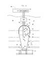
- FIG. 4is a schematic diagram illustrating thermal storage vessel 56 thermally coupled to a heat exchanger 60 according to an embodiment of the invention.
- Thermal storage vessel 56includes a wall 62 forming or bounding an enclosed internal volume 64 substantially filled with water, which in this embodiment, is the thermal storage medium.
- An interior surface 66 of wall 62faces enclosed volume 64
- an exterior surface 68 of wall 62faces the surrounding body of water.
- Wall 62is constructed so as to thermally separate the water within enclosed volume 64 along interior surface 66 from water at ambient temperature along the exterior surface 68 . Thermal transfer between the interior and exterior surfaces 66 , 68 can occur, however, albeit at a slower rate than a direct contact between the water volumes.
- wall 62is constructed of a collapsible material such as a fabric material or a polymer film.
- the fabric material or the polymer filmmay incorporate embedded tensile members to increase its strength and stiffness in either a particular direction or in all directions.
- wall 62may be constructed of discrete tensile members (e.g., cables) with an overlay layer or interconnected by thin flexible sections of material.
- Wall 62includes a top portion 70 forming a dome shape.
- the dome shapecreates a substantially ellipsoidal dome.
- Dome 70is configured to contain the hottest portion of the water within enclosed volume 64 . Forming top portion 70 into a dome reduces wrinkles in wall 62 as well as provides high structural support and less heat transfer surface per unit volume.
- a bottom portion 72 of wall 62includes a side wall 74 coupled to a bottom wall 76 .
- side wall 74is conical, and the diameter thereof diminishes as it approaches bottom wall 76 .
- other shapes for side wall 74are contemplated.
- side wall 74is cylindrical.
- thermal storage vessel 56may be ballasted with a heavy ballast material 78 to supply weight and friction so as to counteract a force applied thereto due to a buoyancy of the water within the internal volume 64 or due to currents in the surrounding body of water, for example.
- ballast material 78includes sediment dredged from near the deployment site or from another site on the seafloor.
- ballast material 78includes materials non-native to the seafloor that are heavier or more dense than water such as, for example, sand, gravel, stone, iron ore, concrete, slag, scrap materials, and the like.
- one or more barriers 80may be positioned about bottom wall 76 to act as a chock to keep the ballast filled part of the vessel 56 from sliding across the seafloor.
- an insulation material 82is coupled to and positioned adjacent to wall 62 so as to increase a thermal insulation of the water within the enclosed volume 64 from the water in the surrounding environment.
- Insulation material 82may be constructed of one or more, insulative materials such as those described below with respect to FIG. 9 , for example. These insulative materials may be collapsible. Insulation material 82 may thus increase the insulation of top portion 70 configured to contain the hottest water while leaving bottom portion 72 more free to exchange heat with the external environment.
- the bottom portion 72may alternatively contain insulation to protect cold storage from the ambient temperature of the environment in cases where the cold fluid is significantly colder than ambient temperature.
- a hot pipe 84extends from pump 58 into enclosed volume 64 , and an opening 86 of hot pipe 84 is positioned to draw in hot water from enclosed volume 64 or to output hot water to enclosed volume 64 .
- an end flow plate 88 coupled to hot pipe 84 near opening 86directs the output flow substantially horizontally, or in one or more directions perpendicular to the direction of heat gradient within enclosed volume 64 . In some embodiments, there is no end flow plate 88 .
- a cold pipe 90extends from pump 58 into enclosed volume 64 , and an opening 92 of cold pipe 90 is positioned to draw in cold water from enclosed volume 64 or to output cold water to enclosed volume 64 .
- Cold pipe 90may also include an end flow plate 94 to direct the cold water output flow to be substantially horizontal.
- cold pipe 90may pass through thermal storage vessel 56 via side wall 74 at a level of temperature gradient substantially equal to an expected input/output temperature of cold water passing through cold pipe 90 .
- top portion 70may include one or more baffles 96 having an opening 98 or openings to manage the vertical flow in sections of the volume 64 .
- the cold water interface pipe 90could terminate in the ambient, surrounding water rather than inside the vessel as shown in phantom.
- holes 99shown in phantom
- side wall 74allow the water in bottom portion 72 to flow in and out, accommodating hot water removed or added to top portion 70 .
- the warm water in top portion 70remains isolated from the ambient or cooled water by thermal stratification (and the associated differential liquid density) and by baffling 96 if included. As long as the openings 99 to the external water are positioned lower than the lowest point that the warm water may reach, the warm water will remain in the enclosure 56 .
- Heat exchanger 60is positioned within or adjacently to C/E 48 such that a heat transfer occurs between the working fluid of C/E 48 and the fluid inside heat exchanger 60 .
- pump 58pumps water from enclosed volume 64 through heat exchanger 60 to transfer heat into or out of the water.
- pump 58may draw cold water through cold pipe 90 and supply the cold water to heat exchanger 60 to transfer heat from the compression heat into the cold water. Accordingly, the cold water is heated, and pump 58 may then supply the hot water through hot pipe 84 to the top of enclosed volume 64 .
- heat exchanger 60is configured to transfer heat into the water to raise a temperature of the water above its 1 atmosphere boiling point ( ⁇ 100° Celsius).
- the ambient water pressure at the position of thermal storage vessel 56 in the sea 40allows the high temperature water to remain in the liquid state at higher pressure.
- the processmay be reversed to draw hot water from one portion of enclosed volume 64 and to supply cold water to another portion thereof.
- the water in enclosed volume 64may be salt water or fresh water.
- Advantages to using fresh waterinclude less corrosion of the heat transfer system components and simpler component construction than that required to endure salt-water exposure.
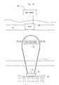
- FIG. 7is a schematic diagram illustrating thermal storage vessel 56 thermally coupled to heat exchanger 60 according to an embodiment of the invention.
- Thermal storage vessel 56includes a hemispherical or ellipsoidal wall 100 defining or bounding an open internal volume 102 substantially filled with water, which in this embodiment, is the thermal storage medium.
- An interior surface 104 of wall 100faces internal volume 102
- an exterior surface 106 of wall 100faces the surrounding body of water.
- Wall 100is constructed so as to thermally insulate the water within internal volume 102 along interior surface 104 from water of the surrounding body of water along the exterior surface 106 .
- Insulation material 82may be constructed of one or more collapsible, insulative materials such as those described below with respect to FIG. 9 , for example. Thermal transfer between the interior and exterior surfaces 104 , 106 is, therefore, significantly reduced.
- this skin 107may be designed to be watertight and, together with wall 100 , provides a complete enclosure around the internal volume 102 .
- FIG. 7also shows another anchoring embodiment coupleable to thermal storage vessel 56 .
- a plurality of anchors or pylons 108may be affixed into the seafloor, and a plurality of anchor cables 110 coupled between anchors 108 and thermal storage vessel 56 secure the buoyancy of thermal storage vessel 56 as well as its position relative to cross currents in the surrounding body of water.
- hot pipe 84extends into a top portion 112 of thermal storage vessel 56 .
- Cold pipe 90may extend into a bottom portion 114 of thermal storage vessel 56 in one example. According to another example, since water from the ambient environment is allowed to enter internal volume 102 due to a withdrawal of hot water therefrom, cold pipe 90 may extend into the surrounding body of water.
- FIG. 8is a schematic diagram illustrating thermal storage vessel 56 of FIG. 7 thermally coupled to a heat exchanger 116 according to another embodiment of the invention.
- FIG. 8illustrates that the location of heat exchange between the water in internal volume 102 with the working fluid of thermal source 49 C/E is within internal volume 102 itself rather than at C/E 48 as illustrated in FIG. 4 or 7 .
- pump 58is configured to cause the working fluid of C/E 48 to flow through thermal storage vessel 56 and into heat exchanger 116 to heat or cool the water in internal volume 102 .
- the heat sourcemay have its own pumping function to move the working fluid through the circuit and heat exchanger 60 . In this manner, de-stratification of thermal gradients established in internal volume 102 is not enhanced via the intake or output of water from a hot or cold pipe.
- FIG. 8also shows an alternative anchor 118 coupleable to thermal storage vessel 56 .
- Anchor 118in one example, includes a bag filled with ballast material 78 native or non-native to the seafloor such as that described above.
- anchor 118may be any weighted object sufficiently heavy to substantially maintain a position of thermal storage vessel 56 when subjected to translational forces.
- FIG. 9illustrates a multi-layer wall 120 of thermal storage vessel 56 according to an embodiment of the invention.
- Wall 120includes a first layer 122 constructed of a collapsible, fiber-reinforced polymer film.
- the filmis a fiber reinforced polymer matrix 124 of, for example, ⁇ 55% fibers 128 encapsulated (such as by hot rolling, for example) in layers of common thermoplastic 126 on both sides.
- Such a matrix 124 structuremay be about 0.14 mm thick (0.055′′), for example. This type of matrix 124 allows for a thin, inexpensive, scalable, and very robust vessel for marine applications.
- the thermoplastic material 126may be plastics such as LDPE (low-density polyethylene), HDPE (high-density polyethylene), PVC (polyvinyl chloride), PET (polyethylene terephthalate), or polyester, as well as a fluoropolymer. Other materials are also contemplated.
- the materialmay also be made of mixed material plastics or of recycled plastic from fluid storage tubes removed from use or operation, for example, where such fluid storage tubes are removed from an installation so as to leave nothing of the removed fluid storage tube at the installation site. Other recyclable plastic sources are also contemplated.
- the fibers 128may be constructed from materials such as glass, carbon, or metal fibers, for example, and are oriented into a directional composite laminate, the direction of which may correspond to one or more directions of principal stress, as an example.
- Fiberglassfor example, is very inexpensive and is generally very tolerant of long-duration water immersion. Fiberglass is also widely used in the marine industry specifically for its durability, reliability, longevity, suitability for the marine environment, and tolerance of saltwater.
- Various types of glass fiberseach have their own advantages in different applications.
- the glass fibersmay be a relatively expensive S-2 glass material, which may be optimized for tensile strength.
- the glass fibersmay be an E-glass material.
- the fiber 128is an important structural element in the thermal storage vessel 56 .
- the tensile strength of the fibersmay be on the order of one-hundred times higher than the thermoplastic matrix that will be used.
- the tension of the fiberopposes the buoyancy force of the thermal storage fluid with the force from the anchoring system (the weight of the sediment ballast for example) and the resultant axial stress in the vessel. These tensions need only be carried vertically through the vessel 56 .
- the designprotects the fiber 128 from the sea water. Attempting to achieve the material strength from the plastic alone may substantially increase the cost of manufacture, and the resulting thickness may not be adequately flexible or collapsible.
- thermoplastic fiber reinforced polymer matrix 124actually exposed to seawater has been extensively used in seawater environments.
- the fibers 128will not be directly exposed to seawater under normal conditions, since they are embedded in the thermoplastic fiber reinforced polymer matrix 124 and then laminated top 130 and bottom 132 to fully encapsulate the fibers 128 .
- the material for outer laminations 130 , 132is generally the same as thermoplastic material 126 in thin “face sheets” to fully encapsulate fibers 128 .
- the fiber reinforced polymer matrix 124 materialis also designed to be repairable. For example, if a hole or a tear develops in the material 124 , the hole may be patched by re-joining the material 124 around the hole or by attaching a patch of the same material or another attachable patch to the material around the hole. In the case of deep deployment, such a patch may be applied by a remotely operated vehicle instead of a diver.
- a second layer 134 of wall 120includes an insulation material constructed of a polymer material entraining a gas. In another embodiment, the polymer material entrains nitrogen, thus forming a neoprene-type insulation material.
- a third layer 136 of wall 120includes another insulation material constructed of a polymer material entraining a gas. In one embodiment, the polymer material of third layer 136 entrains air, thus forming a type of bubble wrap insulation material.
- first layer 122is positioned between second layer 134 and third layer 136 .
- Other embodimentsinclude positioning one or more insulation layers on only one side of first layer 122 .
- Embodiments of the inventioninclude design and operation of thermal storage vessels with existing marine CAES systems in addition to other non-CAES systems where storage of thermal energy under water is desirable.
- An underwater thermal storage vessel according to an embodiment of the inventionallows for the manufacture and deployment of a low-cost thermal storage system.
- FIG. 10illustrates a generic process diagram where a multi-staged compression and expansion system 150 harvests thermal energy from the compression process, stores it in a thermal energy storage medium, and then provides that heat to an expansion process.
- the thermal energy storage mediumis stored in a thermal enclosure 152 such as a thermal enclosure as described above, for example.
- the compression/expansion processis shown with the different elements nested inside.
- the number of stages 154 selected for the applicationmay vary depending on the ultimate pressure that the air is compressed to and the desired maximum temperature in the thermal energy storage 152 . It is shown with a generic N number of stages 154 .
- each stage 154there is a compression step and a heat-exchange process for a compression sequence.
- the heat exchangemay be sequential (that is, heat may be removed from the compressed air after compression) or in some embodiments, the heat exchange may be simultaneous with the compression.
- the airis compressed in series. That is, the same air goes from one stage 154 to the next—with the pressure increasing with each step.
- a typical embodiment of the heat exchangeis where a manifold of cooler thermal material is provided to all the stages 154 in parallel. That is, the thermal material only goes through one stages 154 , so if there were five stages, for example, there are five parallel flows generally fed from a common cool zone in the TES 152 and similarly combined together to and injected into the warm zone in the TES 152 at a common temperature.
- a pump 156is used to circulate the thermal material throughout the stages 154 .
- Mechanical power 158is used to drive the compressed air through the system.
- the expansion processis, in general, a reversal of the compression process. In fact, in some embodiments, the same equipment, simply running from the high-pressure source back to ambient generating mechanical power may be used.
- the heat exchange processis similar as in the compression process except that the heat drawn from the TES 152 is added before or simultaneous with the expansion (in contrast with after or simultaneous in the compression mode). Again, the air pressure is sequentially modulated, and the thermal material is provided in parallel to the heat exchange process.
- FIG. 11illustrates a thermal enclosure 248 with a domed top 250 , a cylindrical wall 252 , and a base 254 .
- a structurecould be placed on grade or on a supporting surface 256 such as the ground.
- base 254may be curved or domed, and thermal enclosure 248 may be positioned below grade such that at least a portion of thermal enclosure 248 extends below the surface of supporting surface 256 .
- Such large-scale thermal enclosures 248can be constructed with reasonable costs that have good structural and thermal insulation properties. Extra insulation may be added to increase the thermal insulation capability of thermal enclosure 248 .
- FIG. 12illustrates one example of a thermal storage tank 258 that is below grade.
- a depression or excavation 260is formed below ground 261 and may be filled with an insulating material 262 , such as a foam (e.g., polyisocyanurate) or a generally natural insulating material like a low conductivity mineral (e.g., vermiculite or diatomaceous earth) or straw. Dry earth may also be used, is relatively inexpensive, and may already be present at the base of the depression or excavation 260 .
- a waterproof liner 264which could be similar to a geotextile or simple thermoplastic film or sheet much like those used to line landfills.
- liner 264can be comprised of tilt-up or other simple concrete structures that are familiar to those of skill in the art. Consideration of the temperatures of the water or thermal material could affect the liner material selection. Butyl liners are commonly used for some solar hot water tanks and comprise suitable material in some situations. One important heat loss mechanism is evaporative cooling. A water vapor-resistant cover 266 substantially reduces evaporative heat loss. If the storage medium to be used in tank 258 is not going to operate with temperature above its boiling temperatures at external ambient pressure, then the structure of cover 266 does not need to be strengthened due to the vapor pressure of the storage medium. For such cases, cover 266 could be a similar membrane as the liner 264 as it will experience similar temperatures.
- the design of tank 258is able to handle storage medium temperatures above the ambient boiling point of the storage medium.
- cover 266may be configured to be able to withstand a substantial amount of vapor pressure.
- a domed cover structure 266may used as shown in phantom.
- the domed cover structure 266can be constructed of concrete.
- the cover 266may be constructed of a thin, flexible membrane.
- one or more layers of additional insulation 268is present.
- the cover 266 of the enclosure 258may have condensing thermal storage material on its bottom, which generally has high heat transfer coefficients.
- a layer of insulation 268could take the form of a polymeric material entraining a gas, such as bubble wrap, spray-on polyurethane foam, or neoprene. It could be a fibrous material such as straw or fiberglass. It could also be a layer of insulation against radiative heat loss, such as a thin reflective sheet of aluminum-coated PET. Bubble wrap is also commonly used to reduce radiative heat loss in these applications, as a part of aluminum-coated laminated assemblies. Insulation layer 268 may have features that help it to withstand elements of the external environment such as weather conditions, solar radiation, high winds, and precipitation.
- such featuresinclude supporting one or more portions of the cover layer 268 at elevations higher than its edges to shed precipitation and provide some interstitial support in high winds.
- the layer 268may have several layers where the inner insulating layer is optimized for resisting the heat and moisture of the heat storage medium, an additional low cost insulation layer, and then an external layer with UV resistance, external waterproofing, and sufficient strength and stiffness for coping with winds and other climate elements.
- FIG. 13illustrates a self-contained thermal enclosure 280 , utilizing an ISO shipping container as a shell for supporting the interior components.
- the enclosuremay be another container of standard ISO shipping container size and incorporating handling interfaces for extra modularity.
- the viewis a section view with a top wall and side wall removed to help illustrate the components of thermal enclosure 280 .
- Insulation 282may be placed against the walls 281 of the enclosure.
- a liner 284 on the sides 283 and floor 285can be a single piece that keeps the insulation 282 dry.
- a similar insulation 282 liner material 284may be placed on the top and side walls not shown.
- hot and cold lines or pipes 290 , 288enter the enclosure 280 near each other for ease of plumbing to the rest of the system.
- the cold pipe 288in this embodiment, is then routed to the bottom of the tank 280 by one of several possible paths. It can be beneficial to have the hot and cold pipes 290 , 288 access areas near the top and bottom of the tank 280 , respectively, to maximize thermal potential in the thermal enclosure 280 .
- the cold line 288can be insulated inside the enclosure to reduce heat exchange if it traverses a warmer section of the thermal fluid to be used in enclosure 280 . Either the cold line 288 or the hot line 290 may be insulated as well, outside the enclosure.
- Two baffles 292are shown that can assist with maintaining thermal stratification, though in different embodiments there may be more or fewer baffles 292 .
- FIG. 14illustrates an insulated pressure vessel 294 .
- One advantage of this designis the high maximum temperatures that can be achieved. Using widely available propane tanks with water as the storage medium, for instance, would allow peak temperatures of ⁇ 220 deg C. This is more than a factor of two higher than the temperature rise from ambient to maximum storage temperature compared to a vessel incapable of significant internal pressure. It also comes with a more expensive vessel. However, the management of the input temperatures by design of the multi-stage pressure-modifying system allows for the temperature rise and thus the vessel costs to be reasonable.
- multiple pressure vessels 294may be packaged in a rectangular, prismatic arrangement by nesting the containers 294 together—with the interstitial volumes between and around the round tanks 294 as air gap insulation or filled with insulation. The combined assembly could then be placed in an ISO-sized container, and multiple containers can be combined to build a bigger and highly efficient thermal storage system.
- thermal enclosureOne key factor that generally improves thermal isolation and therefore heat loss when storing heat is maximizing the volume of the storage to the surface area of the thermal enclosure. As such there is marginal benefit to designing shapes with aspect ratios near unity, for example spheres or cubes. For the embodiments where a modular thermal enclosure is used like those shown in FIG. 13 , multiple thermal enclosures could be stacked and packaged very close together to reduce the external surface areas exposed to the ambient temperatures by sealing the seams between the containers the walls that are adjacent to other modules. In this way, high volumes to effective external surface areas can be achieved even with smaller sub elements and less ideal shapes.
- a thermal energy storage systemincludes a container positioned within a surrounding body of water and comprising a container wall.
- the wallhas an interior surface exposed to and defining an internal volume of the container and has an exterior surface opposite the interior surface and exposed to the surrounding body of water.
- the internal volumeis substantially full of water, and the container is configured to thermally separate water within the internal volume along the interior surface from water of the surrounding body of water along the exterior surface.
- a thermal source in thermal communication with the water within the internal volumeis configured to transfer a thermal potential to the water within the internal volume.
- a method of deploying a thermal energy storage systemincludes positioning a thermal storage container within a body of water.
- the thermal storage containerincludes a wall having a first surface facing a first volume positioned within an interior of the container and a second surface opposite from the first surface and facing the body of water.
- the methodalso includes thermally coupling a thermal source to an entrained volume of water substantially filling the first volume, the thermal source configured to transfer heat to the entrained volume of water.
- the wallis configured to impede a transfer of thermal energy therethrough from the body of water to the entrained volume of water.
Landscapes
- Engineering & Computer Science (AREA)
- Chemical & Material Sciences (AREA)
- Combustion & Propulsion (AREA)
- General Engineering & Computer Science (AREA)
- Sustainable Development (AREA)
- Mechanical Engineering (AREA)
- Life Sciences & Earth Sciences (AREA)
- Sustainable Energy (AREA)
- Oceanography (AREA)
- General Life Sciences & Earth Sciences (AREA)
- Biodiversity & Conservation Biology (AREA)
- Filling Or Discharging Of Gas Storage Vessels (AREA)
- Heat-Pump Type And Storage Water Heaters (AREA)
Abstract
Description
Claims (17)
Priority Applications (1)
| Application Number | Priority Date | Filing Date | Title |
|---|---|---|---|
| US13/183,266US9557079B2 (en) | 2010-07-14 | 2011-07-14 | System and method for storing thermal energy |
Applications Claiming Priority (3)
| Application Number | Priority Date | Filing Date | Title |
|---|---|---|---|
| US36436810P | 2010-07-14 | 2010-07-14 | |
| US36436410P | 2010-07-14 | 2010-07-14 | |
| US13/183,266US9557079B2 (en) | 2010-07-14 | 2011-07-14 | System and method for storing thermal energy |
Publications (2)
| Publication Number | Publication Date |
|---|---|
| US20120012276A1 US20120012276A1 (en) | 2012-01-19 |
| US9557079B2true US9557079B2 (en) | 2017-01-31 |
Family
ID=45465978
Family Applications (1)
| Application Number | Title | Priority Date | Filing Date |
|---|---|---|---|
| US13/183,266Expired - Fee RelatedUS9557079B2 (en) | 2010-07-14 | 2011-07-14 | System and method for storing thermal energy |
Country Status (7)
| Country | Link |
|---|---|
| US (1) | US9557079B2 (en) |
| EP (1) | EP2593676A4 (en) |
| JP (1) | JP5928841B2 (en) |
| KR (1) | KR20130127426A (en) |
| CN (1) | CN103080542B (en) |
| CA (1) | CA2804806C (en) |
| WO (1) | WO2012009569A2 (en) |
Cited By (3)
| Publication number | Priority date | Publication date | Assignee | Title |
|---|---|---|---|---|
| US11486654B2 (en)* | 2017-11-16 | 2022-11-01 | Siemens Gamesa Renewable Energy Gmbh & Co. Kg | Arrangement for storing thermal energy |
| US20230193871A1 (en)* | 2019-01-23 | 2023-06-22 | Mauro Pedretti | Method and device for storing energy |
| US20240093833A1 (en)* | 2022-09-20 | 2024-03-21 | WestGen Energy, LLC | System for underwater compressed gas storage |
Families Citing this family (13)
| Publication number | Priority date | Publication date | Assignee | Title |
|---|---|---|---|---|
| CN102859118A (en)* | 2010-03-01 | 2013-01-02 | 布莱特能源存储科技有限责任公司 | Rotary compressor-expander systems and associated methods of use and manufacture |
| US8978769B2 (en)* | 2011-05-12 | 2015-03-17 | Richard John Moore | Offshore hydrocarbon cooling system |
| CA2839949A1 (en) | 2011-06-28 | 2013-01-03 | Bright Energy Storage Technologies, Llp | Semi-isothermal compression engines with separate combustors and expanders, and associated systems and methods |
| CN102269534B (en)* | 2011-07-25 | 2012-11-28 | 天津空中代码工程应用软件开发有限公司 | Spiral-flow-type heat conducting pipe |
| CH706202A1 (en)* | 2012-03-07 | 2013-09-13 | Airlight Energy Ip Sa | Compressed air energy storage. |
| DE102012108222A1 (en) | 2012-04-09 | 2013-10-10 | Stefan Brosig | Compressed gas storage power station i.e. compressed air storage power station, operating method for generating load-sensitive electric power, involves performing temperature change of liquid/gaseous mixture for around less than value |
| FR2993341B1 (en)* | 2012-07-13 | 2014-07-11 | Alfred | COMPRESSED GAS STORAGE FACILITY UNDER WATER AND CORRESPONDING INSTALLATION METHOD |
| US11796225B2 (en)* | 2012-10-18 | 2023-10-24 | American Piledriving Equipment, Inc. | Geoexchange systems including ground source heat exchangers and related methods |
| CN105899442A (en)* | 2014-01-15 | 2016-08-24 | 布莱特能源存储科技有限责任公司 | Underwater energy storage using compressed fluid |
| ES2649562B1 (en)* | 2016-07-08 | 2018-12-05 | Manuel Muñoz Saiz | Alternative or excess energy storage system in pneumatics at the bottom of the sea |
| CA3031322A1 (en)* | 2016-08-12 | 2018-02-15 | J.F. Brennan Company, Inc. | Dredge head assembly and related diver-assisted dredging system and methods |
| US10788012B2 (en) | 2019-01-04 | 2020-09-29 | Aoe Accumulated Ocean Energy Inc. | Ocean powered rankine cycle turbine |
| CN113203113A (en)* | 2021-05-31 | 2021-08-03 | 青岛开源热力设计研究院有限公司 | Cross-season heat storage and supply system and heat storage module thereof |
Citations (118)
| Publication number | Priority date | Publication date | Assignee | Title |
|---|---|---|---|---|
| GB1213112A (en) | 1968-02-14 | 1970-11-18 | William Joseph Lang | Method and apparatus for increasing the efficiency of electric power generating plants |
| US3670839A (en) | 1969-07-23 | 1972-06-20 | Western Geophysical Co | Extended area acoustic impulse generator |
| US3783615A (en) | 1970-10-29 | 1974-01-08 | C Hubers | Expansion engine |
| US3797973A (en) | 1971-10-01 | 1974-03-19 | Ramsey Corp | Slipper type apex seal for rotary piston engine |
| US3866058A (en) | 1972-07-22 | 1975-02-11 | Rhein Westfael Elect Werk Ag | Power-generating system and method |
| US3883273A (en) | 1971-10-29 | 1975-05-13 | Copeland Corp | Rotary chamber-type compressor |
| US3895493A (en) | 1972-05-03 | 1975-07-22 | Georges Alfred Rigollot | Method and plant for the storage and recovery of energy from a reservoir |
| US3896898A (en) | 1973-06-06 | 1975-07-29 | Exxon Production Research Co | High frequency seismic source using compressed air |
| US3916634A (en) | 1973-03-12 | 1975-11-04 | Roy J Woodruff | Method for forming holes in earth and setting subterranean structures therein |
| US3970050A (en) | 1975-03-07 | 1976-07-20 | Hoadley Harry W | Two-stage rotary engines |
| US3996741A (en) | 1975-06-05 | 1976-12-14 | Herberg George M | Energy storage system |
| US4116009A (en)* | 1976-08-24 | 1978-09-26 | Daubin Scott C | Compliant underwater pipe system |
| JPS5411517A (en) | 1977-06-28 | 1979-01-27 | Agency Of Ind Science & Technol | Marine pressurized water type energy storing method |
| GB2013318A (en) | 1978-01-06 | 1979-08-08 | Motor Columbus Ing | Constant pressure compressed gas energy storage system and method |
| GB2020375A (en) | 1978-05-02 | 1979-11-14 | Ermini A | System of storing energy as gas pressure |
| WO1979001154A1 (en) | 1978-05-31 | 1979-12-27 | Zeman H | Air pressure tank immersed in a lake |
| WO1979001158A1 (en) | 1978-05-31 | 1979-12-27 | Zeman H | Air pressure tank |
| US4206601A (en) | 1978-06-26 | 1980-06-10 | Benasutti Asst., Ltd. | Compressed air producing, tidal and wave-power collection apparatus for installation in large bodies of water |
| JPS55109772A (en) | 1978-12-29 | 1980-08-23 | Ryoji Muneto | Gravity buoyancy power plant |
| US4232983A (en) | 1978-12-07 | 1980-11-11 | Sidney F. Cook | Offshore submarine storage facility for highly chilled liquified gases |
| US4245475A (en) | 1978-06-19 | 1981-01-20 | Girden Barney B | Method and apparatus for producing electricity from thermal sea power |
| JPS5610897A (en) | 1979-07-06 | 1981-02-03 | Fumio Otsu | Underwater storaging and mooring arrangement for compressed gas |
| JPS5677568A (en) | 1979-11-28 | 1981-06-25 | Atsuji Sugimoto | Water column pressure energy converter |
| US4289425A (en) | 1978-06-16 | 1981-09-15 | Fumio Ootsu | Underwater accumulator for pressurized gas |
| JPS56148682A (en) | 1980-04-16 | 1981-11-18 | Akira Nishi | Generating device utilizing ocean current or tidal current |
| JPS578363A (en) | 1980-06-19 | 1982-01-16 | Kenji Horii | Energy storage generator using submarine compressed air tank |
| US4391552A (en) | 1981-08-24 | 1983-07-05 | Bechtel International Corp. | Apparatus and method for eliminating champagne effect in compressed air energy storage systems |
| JPS58214608A (en) | 1982-06-09 | 1983-12-13 | Mitsui Eng & Shipbuild Co Ltd | Energy storage device |
| US4454721A (en) | 1981-09-18 | 1984-06-19 | Bbc Brown, Boveri & Company, Limited | Constant-pressure air-storage cavern with hydralic pressure compensation for air-storage gas turbine power stations |
| US4560884A (en) | 1979-07-16 | 1985-12-24 | Whittecar William C | Wave power energizer |
| JPS63239320A (en) | 1987-03-27 | 1988-10-05 | Takenaka Komuten Co Ltd | Underwater energy storage device |
| DE3720872A1 (en) | 1987-06-24 | 1989-01-05 | Kurt Meyer | Tidal power station |
| US4848445A (en) | 1987-10-28 | 1989-07-18 | Allied-Signal Inc. | Heat transfer apparatus and method |
| US4873828A (en) | 1983-11-21 | 1989-10-17 | Oliver Laing | Energy storage for off peak electricity |
| JPH0270238A (en) | 1988-09-05 | 1990-03-09 | Nec Corp | Charging device for unmanned carrying car |
| JPH0271053A (en) | 1988-09-07 | 1990-03-09 | Kawasaki Heavy Ind Ltd | compressed air energy storage system |
| JPH0271054A (en) | 1988-09-07 | 1990-03-09 | Kawasaki Heavy Ind Ltd | compressed air energy storage system |
| JPH02271080A (en) | 1989-04-12 | 1990-11-06 | Central Res Inst Of Electric Power Ind | Ocean/waste heat temperature difference generating system |
| JPH0349564A (en) | 1989-07-13 | 1991-03-04 | Matsushita Electric Works Ltd | Dc/ac inverter |
| CA2027113A1 (en) | 1990-10-09 | 1992-04-10 | Giancarlo Morocutti | Ocean wave air compressor |
| US5184936A (en) | 1988-09-21 | 1993-02-09 | Yugen Kaisha Parasight | Multiple-gas-phase tidal power generation apparatus and method |
| US5205720A (en) | 1990-07-03 | 1993-04-27 | Tsugio Nagata | Method and apparatus for producing compressed air and water pumping apparatus utilizing the produced air |
| JPH05294387A (en) | 1992-04-09 | 1993-11-09 | Hiroshi Sekiya | Storage device and method for effective use of energy |
| JPH0650109A (en) | 1991-12-27 | 1994-02-22 | Yoshibumi Utsunomiya | Underwater power generation system and underwater power generation method |
| CN2168973Y (en) | 1993-04-24 | 1994-06-15 | 王义锐 | Deep-well pump |
| JPH06173841A (en) | 1992-12-02 | 1994-06-21 | Akira Nishi | Compressed air producing method |
| DE4307094A1 (en) | 1993-03-06 | 1994-09-08 | Physikalisch Tech Entwicklungs | Compressed-air store |
| US5391067A (en) | 1993-07-20 | 1995-02-21 | Saunders; James E. | Rotary fluid displacement device |
| JPH07317649A (en) | 1994-05-27 | 1995-12-05 | Les-Ben:Kk | Solar power generation device and power generation method thereof |
| US5537822A (en) | 1994-02-03 | 1996-07-23 | The Israel Electric Corporation Ltd. | Compressed air energy storage method and system |
| ES2089955A2 (en) | 1993-12-23 | 1996-10-01 | Vicente Emilio Pajares | Hydropneumatic process for obtaining and storing pneumatic energy from the force of the wind in order to produce electrical energy |
| US5841733A (en) | 1996-05-31 | 1998-11-24 | Hydroacoustics Inc. | Acoustic source array system for underwater operation |
| JPH1177838A (en) | 1997-09-12 | 1999-03-23 | Junsuke Hagiwara | Manufacture of fabric molding |
| US5946909A (en) | 1997-05-23 | 1999-09-07 | Swort International, Inc. | Floating turbine system for generating power |
| US6018947A (en) | 1998-08-06 | 2000-02-01 | Demarco; Adolph N. | System and process for recovering energy from a compressed gas |
| JP2000175377A (en) | 1998-12-03 | 2000-06-23 | Sumitomo Heavy Ind Ltd | Energy storing system |
| WO2001033150A1 (en) | 1999-11-03 | 2001-05-10 | Lectrix Llc | Compressed air energy storage system with an air separation unit |
| CN1296327A (en) | 1999-11-10 | 2001-05-23 | 赵克 | Hydraulic driven magnetic suspension permanent magnet generator system for ships and warships |
| US20020119010A1 (en) | 2001-02-26 | 2002-08-29 | Len-Rios Felipe Antonio | Ship lift system and method for transportation of ships with recycling water system in canal |
| US20020178987A1 (en) | 2001-04-11 | 2002-12-05 | Dana Eagles | Spiral formed flexible fluid containment vessel |
| KR20030031012A (en) | 2003-01-08 | 2003-04-18 | 이병호 | Wind power and hydro power plant using two compartments |
| US6575712B1 (en) | 2001-09-28 | 2003-06-10 | Slavcho Slavchev | Air compressor system |
| WO2003078812A1 (en) | 2002-03-20 | 2003-09-25 | Alstom (Switzerland) Ltd | Compressed air energy storage system with a heat maintenance system |
| US6659065B1 (en) | 2002-08-12 | 2003-12-09 | David C Renegar | Flexible vane rotary engine |
| US20040074235A1 (en) | 2002-08-16 | 2004-04-22 | Lampkin Beatrice Campbell | Electricity produced by CO2, air and water |
| US6748737B2 (en) | 2000-11-17 | 2004-06-15 | Patrick Alan Lafferty | Regenerative energy storage and conversion system |
| KR20040092336A (en) | 2003-04-24 | 2004-11-03 | 성삼표 | Balance airmotor |
| US6863474B2 (en) | 2003-03-31 | 2005-03-08 | Dresser-Rand Company | Compressed gas utilization system and method with sub-sea gas storage |
| US6892681B2 (en)* | 2003-03-31 | 2005-05-17 | Denso Corporation | Heat storage tank |
| US20050158184A1 (en) | 2004-01-15 | 2005-07-21 | Tah Shan Lin | Pressure reservoir structure for use in water |
| KR20050076176A (en) | 2004-01-19 | 2005-07-26 | 삼성전자주식회사 | System and method for communicating between ipv6 mobile ad-hoc network and external network |
| FR2866096A1 (en) | 2004-02-06 | 2005-08-12 | Georges Bouchet | Electrical energy storing device, has air compression assembly with air compressor that produces compressed air utilizing electrical energy, and turbine assuring expansion and reheating of compressed air, using geothermal and solar energy |
| US6964165B2 (en) | 2004-02-27 | 2005-11-15 | Uhl Donald A | System and process for recovering energy from a compressed gas |
| EP1638191A2 (en) | 2004-09-17 | 2006-03-22 | Active Power, Inc. | Systems and methods for providing cooling in compressed air storage power supply systems |
| JP2006077719A (en) | 2004-09-13 | 2006-03-23 | Teruji Yokosuka | Groundwater flow power generation method using water pressure, compressed air and atmospheric pressure and its power generation mechanism |
| GR1005210B (en) | 2005-05-27 | 2006-05-04 | Θαλασσια Μηχανικη Α.Ε. | System for electricity production from multiple sources with multiple uses, based on the exploitation of wave energy |
| US7097436B2 (en) | 2004-02-17 | 2006-08-29 | Wells David S | Apex split seal |
| US20060201454A1 (en)* | 2005-02-22 | 2006-09-14 | Denso Corporation | Heat storage tank |
| FR2885961A1 (en) | 2005-05-19 | 2006-11-24 | Marcel Pillet | Maritime installation for producing energy, has ballasting tank filled with water for permitting partial or total immersion of installation during storm, and control unit for controlling operation of solenoid valve and sump pump |
| EP1734255A1 (en) | 2005-05-27 | 2006-12-20 | Thalassia Michaniki AE | Wave energy converter |
| US20070006586A1 (en) | 2005-06-21 | 2007-01-11 | Hoffman John S | Serving end use customers with onsite compressed air energy storage systems |
| EP1764494A1 (en) | 2005-09-20 | 2007-03-21 | Pierre Benaros | Electrical energy storage and recovery facility |
| US20070089682A1 (en) | 2005-10-24 | 2007-04-26 | Reynaldo Mariansky | Integrated ocean wave harness unit |
| US7216483B2 (en) | 2003-11-10 | 2007-05-15 | Takeuchi Mfg. Co., Ltd. | Power generating system utilizing buoyancy |
| US20070130929A1 (en) | 2005-12-13 | 2007-06-14 | Ghazi Khan | Wave power generator |
| CN2924492Y (en) | 2006-02-23 | 2007-07-18 | 温州恒海科技有限公司 | Air energy-storage volume pipe liquid flow calibrating device |
| CN200949502Y (en) | 2006-08-25 | 2007-09-19 | 胡大林 | Water pressurized energy accumulating type wind power field |
| US20070234749A1 (en) | 2006-04-05 | 2007-10-11 | Enis Ben M | Thermal energy storage system using compressed air energy and/or chilled water from desalination processes |
| US7281371B1 (en) | 2006-08-23 | 2007-10-16 | Ebo Group, Inc. | Compressed air pumped hydro energy storage and distribution system |
| KR20070115019A (en) | 2006-05-30 | 2007-12-05 | 김종오 | Surf energy inverter |
| US20070295673A1 (en) | 2006-04-05 | 2007-12-27 | Enis Ben M | Desalination method and system using compressed air energy systems |
| US20080012344A1 (en) | 2006-05-16 | 2008-01-17 | Keith Buffard | Wave energy converter with air compression (WECWAC) |
| US20080034756A1 (en) | 2004-05-08 | 2008-02-14 | Egils Spalte | Air Compression Heat Accumulating Power Plant With An Underground Heat Accumulator Formed In The Aquifer (Gaes) |
| CN101158329A (en) | 2007-10-08 | 2008-04-09 | 李林海 | Sea driven respiration energy converting system |
| RU2321776C1 (en) | 2006-06-08 | 2008-04-10 | Общество С Ограниченной Ответственностью "Лкц-Наука" | Power plant with hydraulic compressor |
| WO2008045468A1 (en) | 2006-10-10 | 2008-04-17 | Regents Of The University Of Minnesota | Open accumulator for compact liquid power energy storage |
| US7362490B2 (en) | 2004-11-11 | 2008-04-22 | Lg Chem, Ltd. | Electrochromic mirror or window displaying information |
| TW200831777A (en) | 2007-01-26 | 2008-08-01 | rui-qi Tong | Fluid kinetic energy device |
| US20080226480A1 (en) | 2007-03-15 | 2008-09-18 | Ion Metrics, Inc. | Multi-Stage Trochoidal Vacuum Pump |
| US20080260548A1 (en) | 2007-04-19 | 2008-10-23 | Ahdoot Ned M | Wave energy converter |
| TW200842250A (en) | 2007-04-19 | 2008-11-01 | Tien-Chuan Chen | Hydroelectric power generator using wind power and water power to compress air |
| US7448404B2 (en)* | 2002-10-23 | 2008-11-11 | Navion Asa | Seabed located storage |
| CN101302751A (en) | 2008-06-12 | 2008-11-12 | 邢承兴 | Large power underwater constant pressure storage plant |
| JP2008309014A (en) | 2007-06-13 | 2008-12-25 | Kansai Electric Power Co Inc:The | Osmotic pressure type compressed air storage turbine generator system |
| US7470086B2 (en) | 2006-01-04 | 2008-12-30 | Clifford Allen Jennings | Submersible tethered platform for undersea electrical power generation |
| WO2009005383A1 (en) | 2007-07-03 | 2009-01-08 | Fernando Carlos Santos Pereira | Joint system for convertion of eolic, solar, sea waves and marine current energies |
| US20090021012A1 (en) | 2007-07-20 | 2009-01-22 | Stull Mark A | Integrated wind-power electrical generation and compressed air energy storage system |
| WO2009015419A1 (en) | 2007-07-30 | 2009-02-05 | Buoyancy Hydro Pty Ltd | Buoyancy hydro power generator and method |
| CN101368395A (en) | 2008-05-07 | 2009-02-18 | 陈鸣 | Pressure accumulation water supply system |
| WO2009024933A2 (en) | 2007-08-22 | 2009-02-26 | Universidade Da Beira Interior | Aquatic system for energy storage in the form of compressed air |
| CN201212166Y (en) | 2008-05-07 | 2009-03-25 | 陈鸣 | Solar water supply installation |
| US7525212B1 (en) | 2005-06-20 | 2009-04-28 | Chris S Catlin | Ocean power harvester |
| US20090158740A1 (en) | 2007-12-21 | 2009-06-25 | Palo Alto Research Center Incorporated | Co2 capture during compressed air energy storage |
| JP2009525432A (en) | 2006-01-31 | 2009-07-09 | エム. エニス,ベン | Improved method of transporting and storing wind energy using pipelines |
| US20090178384A1 (en) | 2007-01-25 | 2009-07-16 | Michael Nakhamkin | CAES plant using humidified air in the bottoming cycle expander |
| US20090230696A1 (en) | 2008-01-24 | 2009-09-17 | Enis Ben M | Method and apparatus for using solar energy to enhance the operation of a compressed air energy storage system |
| US7614861B2 (en) | 2004-08-17 | 2009-11-10 | Hydro-Industries Tynat Ltd. | Rotary fluid-driven motor with sealing elements |
| JP2010011732A (en) | 2008-06-25 | 2010-01-14 | Siemens Ag | Energy storing system and method therefor to store and supply energy |
Family Cites Families (1)
| Publication number | Priority date | Publication date | Assignee | Title |
|---|---|---|---|---|
| US4958956A (en)* | 1987-09-23 | 1990-09-25 | Shimizu Construction Co., Ltd. | Submerged flexible wave restraining structure and a method of constructing it |
- 2011
- 2011-07-14EPEP11807534.0Apatent/EP2593676A4/ennot_activeWithdrawn
- 2011-07-14CNCN201180040987.4Apatent/CN103080542B/ennot_activeExpired - Fee Related
- 2011-07-14CACA2804806Apatent/CA2804806C/enactiveActive
- 2011-07-14KRKR1020137003597Apatent/KR20130127426A/ennot_activeWithdrawn
- 2011-07-14WOPCT/US2011/044065patent/WO2012009569A2/enactiveApplication Filing
- 2011-07-14JPJP2013519837Apatent/JP5928841B2/ennot_activeExpired - Fee Related
- 2011-07-14USUS13/183,266patent/US9557079B2/ennot_activeExpired - Fee Related
Patent Citations (121)
| Publication number | Priority date | Publication date | Assignee | Title |
|---|---|---|---|---|
| GB1213112A (en) | 1968-02-14 | 1970-11-18 | William Joseph Lang | Method and apparatus for increasing the efficiency of electric power generating plants |
| US3670839A (en) | 1969-07-23 | 1972-06-20 | Western Geophysical Co | Extended area acoustic impulse generator |
| US3783615A (en) | 1970-10-29 | 1974-01-08 | C Hubers | Expansion engine |
| US3797973A (en) | 1971-10-01 | 1974-03-19 | Ramsey Corp | Slipper type apex seal for rotary piston engine |
| US3883273A (en) | 1971-10-29 | 1975-05-13 | Copeland Corp | Rotary chamber-type compressor |
| US3895493A (en) | 1972-05-03 | 1975-07-22 | Georges Alfred Rigollot | Method and plant for the storage and recovery of energy from a reservoir |
| US3866058A (en) | 1972-07-22 | 1975-02-11 | Rhein Westfael Elect Werk Ag | Power-generating system and method |
| US3916634A (en) | 1973-03-12 | 1975-11-04 | Roy J Woodruff | Method for forming holes in earth and setting subterranean structures therein |
| US3896898A (en) | 1973-06-06 | 1975-07-29 | Exxon Production Research Co | High frequency seismic source using compressed air |
| US3970050A (en) | 1975-03-07 | 1976-07-20 | Hoadley Harry W | Two-stage rotary engines |
| US3996741A (en) | 1975-06-05 | 1976-12-14 | Herberg George M | Energy storage system |
| US4116009A (en)* | 1976-08-24 | 1978-09-26 | Daubin Scott C | Compliant underwater pipe system |
| JPS5411517A (en) | 1977-06-28 | 1979-01-27 | Agency Of Ind Science & Technol | Marine pressurized water type energy storing method |
| JPS6037316B2 (en) | 1977-06-28 | 1985-08-26 | 工業技術院長 | Pressurized water energy usage method |
| GB2013318A (en) | 1978-01-06 | 1979-08-08 | Motor Columbus Ing | Constant pressure compressed gas energy storage system and method |
| GB2020375A (en) | 1978-05-02 | 1979-11-14 | Ermini A | System of storing energy as gas pressure |
| WO1979001154A1 (en) | 1978-05-31 | 1979-12-27 | Zeman H | Air pressure tank immersed in a lake |
| WO1979001158A1 (en) | 1978-05-31 | 1979-12-27 | Zeman H | Air pressure tank |
| US4289425A (en) | 1978-06-16 | 1981-09-15 | Fumio Ootsu | Underwater accumulator for pressurized gas |
| US4245475A (en) | 1978-06-19 | 1981-01-20 | Girden Barney B | Method and apparatus for producing electricity from thermal sea power |
| US4206601A (en) | 1978-06-26 | 1980-06-10 | Benasutti Asst., Ltd. | Compressed air producing, tidal and wave-power collection apparatus for installation in large bodies of water |
| US4232983A (en) | 1978-12-07 | 1980-11-11 | Sidney F. Cook | Offshore submarine storage facility for highly chilled liquified gases |
| JPS55109772A (en) | 1978-12-29 | 1980-08-23 | Ryoji Muneto | Gravity buoyancy power plant |
| JPS5610897A (en) | 1979-07-06 | 1981-02-03 | Fumio Otsu | Underwater storaging and mooring arrangement for compressed gas |
| US4560884A (en) | 1979-07-16 | 1985-12-24 | Whittecar William C | Wave power energizer |
| JPS5677568A (en) | 1979-11-28 | 1981-06-25 | Atsuji Sugimoto | Water column pressure energy converter |
| JPH0118266B2 (en) | 1980-04-16 | 1989-04-05 | Akira Nishi | |
| JPS56148682A (en) | 1980-04-16 | 1981-11-18 | Akira Nishi | Generating device utilizing ocean current or tidal current |
| JPS578363A (en) | 1980-06-19 | 1982-01-16 | Kenji Horii | Energy storage generator using submarine compressed air tank |
| US4391552A (en) | 1981-08-24 | 1983-07-05 | Bechtel International Corp. | Apparatus and method for eliminating champagne effect in compressed air energy storage systems |
| US4454721A (en) | 1981-09-18 | 1984-06-19 | Bbc Brown, Boveri & Company, Limited | Constant-pressure air-storage cavern with hydralic pressure compensation for air-storage gas turbine power stations |
| JPS58214608A (en) | 1982-06-09 | 1983-12-13 | Mitsui Eng & Shipbuild Co Ltd | Energy storage device |
| US4873828A (en) | 1983-11-21 | 1989-10-17 | Oliver Laing | Energy storage for off peak electricity |
| JPS63239320A (en) | 1987-03-27 | 1988-10-05 | Takenaka Komuten Co Ltd | Underwater energy storage device |
| DE3720872A1 (en) | 1987-06-24 | 1989-01-05 | Kurt Meyer | Tidal power station |
| US4848445A (en) | 1987-10-28 | 1989-07-18 | Allied-Signal Inc. | Heat transfer apparatus and method |
| JPH0270238A (en) | 1988-09-05 | 1990-03-09 | Nec Corp | Charging device for unmanned carrying car |
| JPH0271053A (en) | 1988-09-07 | 1990-03-09 | Kawasaki Heavy Ind Ltd | compressed air energy storage system |
| JPH0271054A (en) | 1988-09-07 | 1990-03-09 | Kawasaki Heavy Ind Ltd | compressed air energy storage system |
| US5184936A (en) | 1988-09-21 | 1993-02-09 | Yugen Kaisha Parasight | Multiple-gas-phase tidal power generation apparatus and method |
| JPH02271080A (en) | 1989-04-12 | 1990-11-06 | Central Res Inst Of Electric Power Ind | Ocean/waste heat temperature difference generating system |
| JPH0349564A (en) | 1989-07-13 | 1991-03-04 | Matsushita Electric Works Ltd | Dc/ac inverter |
| US5340283A (en) | 1990-07-03 | 1994-08-23 | Tsugio Nagata | Water pumping apparatus utilizing produced compressed air |
| US5205720A (en) | 1990-07-03 | 1993-04-27 | Tsugio Nagata | Method and apparatus for producing compressed air and water pumping apparatus utilizing the produced air |
| CA2027113A1 (en) | 1990-10-09 | 1992-04-10 | Giancarlo Morocutti | Ocean wave air compressor |
| JPH0650109A (en) | 1991-12-27 | 1994-02-22 | Yoshibumi Utsunomiya | Underwater power generation system and underwater power generation method |
| JPH05294387A (en) | 1992-04-09 | 1993-11-09 | Hiroshi Sekiya | Storage device and method for effective use of energy |
| JPH06173841A (en) | 1992-12-02 | 1994-06-21 | Akira Nishi | Compressed air producing method |
| DE4307094A1 (en) | 1993-03-06 | 1994-09-08 | Physikalisch Tech Entwicklungs | Compressed-air store |
| CN2168973Y (en) | 1993-04-24 | 1994-06-15 | 王义锐 | Deep-well pump |
| US5391067A (en) | 1993-07-20 | 1995-02-21 | Saunders; James E. | Rotary fluid displacement device |
| ES2089955A2 (en) | 1993-12-23 | 1996-10-01 | Vicente Emilio Pajares | Hydropneumatic process for obtaining and storing pneumatic energy from the force of the wind in order to produce electrical energy |
| US5537822A (en) | 1994-02-03 | 1996-07-23 | The Israel Electric Corporation Ltd. | Compressed air energy storage method and system |
| JPH07317649A (en) | 1994-05-27 | 1995-12-05 | Les-Ben:Kk | Solar power generation device and power generation method thereof |
| US5841733A (en) | 1996-05-31 | 1998-11-24 | Hydroacoustics Inc. | Acoustic source array system for underwater operation |
| US5946909A (en) | 1997-05-23 | 1999-09-07 | Swort International, Inc. | Floating turbine system for generating power |
| JPH1177838A (en) | 1997-09-12 | 1999-03-23 | Junsuke Hagiwara | Manufacture of fabric molding |
| US6018947A (en) | 1998-08-06 | 2000-02-01 | Demarco; Adolph N. | System and process for recovering energy from a compressed gas |
| JP2000175377A (en) | 1998-12-03 | 2000-06-23 | Sumitomo Heavy Ind Ltd | Energy storing system |
| WO2001033150A1 (en) | 1999-11-03 | 2001-05-10 | Lectrix Llc | Compressed air energy storage system with an air separation unit |
| CN1296327A (en) | 1999-11-10 | 2001-05-23 | 赵克 | Hydraulic driven magnetic suspension permanent magnet generator system for ships and warships |
| US6748737B2 (en) | 2000-11-17 | 2004-06-15 | Patrick Alan Lafferty | Regenerative energy storage and conversion system |
| US20020119010A1 (en) | 2001-02-26 | 2002-08-29 | Len-Rios Felipe Antonio | Ship lift system and method for transportation of ships with recycling water system in canal |
| US20020178987A1 (en) | 2001-04-11 | 2002-12-05 | Dana Eagles | Spiral formed flexible fluid containment vessel |
| US6575712B1 (en) | 2001-09-28 | 2003-06-10 | Slavcho Slavchev | Air compressor system |
| WO2003078812A1 (en) | 2002-03-20 | 2003-09-25 | Alstom (Switzerland) Ltd | Compressed air energy storage system with a heat maintenance system |
| US6659065B1 (en) | 2002-08-12 | 2003-12-09 | David C Renegar | Flexible vane rotary engine |
| US20040074235A1 (en) | 2002-08-16 | 2004-04-22 | Lampkin Beatrice Campbell | Electricity produced by CO2, air and water |
| US7448404B2 (en)* | 2002-10-23 | 2008-11-11 | Navion Asa | Seabed located storage |
| KR20030031012A (en) | 2003-01-08 | 2003-04-18 | 이병호 | Wind power and hydro power plant using two compartments |
| US6863474B2 (en) | 2003-03-31 | 2005-03-08 | Dresser-Rand Company | Compressed gas utilization system and method with sub-sea gas storage |
| US6892681B2 (en)* | 2003-03-31 | 2005-05-17 | Denso Corporation | Heat storage tank |
| KR20040092336A (en) | 2003-04-24 | 2004-11-03 | 성삼표 | Balance airmotor |
| US7216483B2 (en) | 2003-11-10 | 2007-05-15 | Takeuchi Mfg. Co., Ltd. | Power generating system utilizing buoyancy |
| US20050158184A1 (en) | 2004-01-15 | 2005-07-21 | Tah Shan Lin | Pressure reservoir structure for use in water |
| KR20050076176A (en) | 2004-01-19 | 2005-07-26 | 삼성전자주식회사 | System and method for communicating between ipv6 mobile ad-hoc network and external network |
| FR2866096A1 (en) | 2004-02-06 | 2005-08-12 | Georges Bouchet | Electrical energy storing device, has air compression assembly with air compressor that produces compressed air utilizing electrical energy, and turbine assuring expansion and reheating of compressed air, using geothermal and solar energy |
| US7097436B2 (en) | 2004-02-17 | 2006-08-29 | Wells David S | Apex split seal |
| US6964165B2 (en) | 2004-02-27 | 2005-11-15 | Uhl Donald A | System and process for recovering energy from a compressed gas |
| US20080034756A1 (en) | 2004-05-08 | 2008-02-14 | Egils Spalte | Air Compression Heat Accumulating Power Plant With An Underground Heat Accumulator Formed In The Aquifer (Gaes) |
| US7614861B2 (en) | 2004-08-17 | 2009-11-10 | Hydro-Industries Tynat Ltd. | Rotary fluid-driven motor with sealing elements |
| JP2006077719A (en) | 2004-09-13 | 2006-03-23 | Teruji Yokosuka | Groundwater flow power generation method using water pressure, compressed air and atmospheric pressure and its power generation mechanism |
| EP1638191A2 (en) | 2004-09-17 | 2006-03-22 | Active Power, Inc. | Systems and methods for providing cooling in compressed air storage power supply systems |
| US7362490B2 (en) | 2004-11-11 | 2008-04-22 | Lg Chem, Ltd. | Electrochromic mirror or window displaying information |
| US20060201454A1 (en)* | 2005-02-22 | 2006-09-14 | Denso Corporation | Heat storage tank |
| FR2885961A1 (en) | 2005-05-19 | 2006-11-24 | Marcel Pillet | Maritime installation for producing energy, has ballasting tank filled with water for permitting partial or total immersion of installation during storm, and control unit for controlling operation of solenoid valve and sump pump |
| EP1734255A1 (en) | 2005-05-27 | 2006-12-20 | Thalassia Michaniki AE | Wave energy converter |
| GR1005210B (en) | 2005-05-27 | 2006-05-04 | Θαλασσια Μηχανικη Α.Ε. | System for electricity production from multiple sources with multiple uses, based on the exploitation of wave energy |
| US7525212B1 (en) | 2005-06-20 | 2009-04-28 | Chris S Catlin | Ocean power harvester |
| US20070006586A1 (en) | 2005-06-21 | 2007-01-11 | Hoffman John S | Serving end use customers with onsite compressed air energy storage systems |
| EP1764494A1 (en) | 2005-09-20 | 2007-03-21 | Pierre Benaros | Electrical energy storage and recovery facility |
| US20070089682A1 (en) | 2005-10-24 | 2007-04-26 | Reynaldo Mariansky | Integrated ocean wave harness unit |
| US20070130929A1 (en) | 2005-12-13 | 2007-06-14 | Ghazi Khan | Wave power generator |
| US7470086B2 (en) | 2006-01-04 | 2008-12-30 | Clifford Allen Jennings | Submersible tethered platform for undersea electrical power generation |
| JP2009525432A (en) | 2006-01-31 | 2009-07-09 | エム. エニス,ベン | Improved method of transporting and storing wind energy using pipelines |
| CN2924492Y (en) | 2006-02-23 | 2007-07-18 | 温州恒海科技有限公司 | Air energy-storage volume pipe liquid flow calibrating device |
| US20070295673A1 (en) | 2006-04-05 | 2007-12-27 | Enis Ben M | Desalination method and system using compressed air energy systems |
| US20070234749A1 (en) | 2006-04-05 | 2007-10-11 | Enis Ben M | Thermal energy storage system using compressed air energy and/or chilled water from desalination processes |
| US20080012344A1 (en) | 2006-05-16 | 2008-01-17 | Keith Buffard | Wave energy converter with air compression (WECWAC) |
| KR20070115019A (en) | 2006-05-30 | 2007-12-05 | 김종오 | Surf energy inverter |
| RU2321776C1 (en) | 2006-06-08 | 2008-04-10 | Общество С Ограниченной Ответственностью "Лкц-Наука" | Power plant with hydraulic compressor |
| US7281371B1 (en) | 2006-08-23 | 2007-10-16 | Ebo Group, Inc. | Compressed air pumped hydro energy storage and distribution system |
| CN200949502Y (en) | 2006-08-25 | 2007-09-19 | 胡大林 | Water pressurized energy accumulating type wind power field |
| WO2008045468A1 (en) | 2006-10-10 | 2008-04-17 | Regents Of The University Of Minnesota | Open accumulator for compact liquid power energy storage |
| US20090178384A1 (en) | 2007-01-25 | 2009-07-16 | Michael Nakhamkin | CAES plant using humidified air in the bottoming cycle expander |
| TW200831777A (en) | 2007-01-26 | 2008-08-01 | rui-qi Tong | Fluid kinetic energy device |
| US20080226480A1 (en) | 2007-03-15 | 2008-09-18 | Ion Metrics, Inc. | Multi-Stage Trochoidal Vacuum Pump |
| US20080260548A1 (en) | 2007-04-19 | 2008-10-23 | Ahdoot Ned M | Wave energy converter |
| TW200842250A (en) | 2007-04-19 | 2008-11-01 | Tien-Chuan Chen | Hydroelectric power generator using wind power and water power to compress air |
| JP2008309014A (en) | 2007-06-13 | 2008-12-25 | Kansai Electric Power Co Inc:The | Osmotic pressure type compressed air storage turbine generator system |
| WO2009005383A1 (en) | 2007-07-03 | 2009-01-08 | Fernando Carlos Santos Pereira | Joint system for convertion of eolic, solar, sea waves and marine current energies |
| US20090021012A1 (en) | 2007-07-20 | 2009-01-22 | Stull Mark A | Integrated wind-power electrical generation and compressed air energy storage system |
| WO2009015419A1 (en) | 2007-07-30 | 2009-02-05 | Buoyancy Hydro Pty Ltd | Buoyancy hydro power generator and method |
| WO2009024933A2 (en) | 2007-08-22 | 2009-02-26 | Universidade Da Beira Interior | Aquatic system for energy storage in the form of compressed air |
| CN101158329A (en) | 2007-10-08 | 2008-04-09 | 李林海 | Sea driven respiration energy converting system |
| US20090158740A1 (en) | 2007-12-21 | 2009-06-25 | Palo Alto Research Center Incorporated | Co2 capture during compressed air energy storage |
| US20090230696A1 (en) | 2008-01-24 | 2009-09-17 | Enis Ben M | Method and apparatus for using solar energy to enhance the operation of a compressed air energy storage system |
| CN201212166Y (en) | 2008-05-07 | 2009-03-25 | 陈鸣 | Solar water supply installation |
| CN101368395A (en) | 2008-05-07 | 2009-02-18 | 陈鸣 | Pressure accumulation water supply system |
| CN101302751A (en) | 2008-06-12 | 2008-11-12 | 邢承兴 | Large power underwater constant pressure storage plant |
| JP2010011732A (en) | 2008-06-25 | 2010-01-14 | Siemens Ag | Energy storing system and method therefor to store and supply energy |
Cited By (4)
| Publication number | Priority date | Publication date | Assignee | Title |
|---|---|---|---|---|
| US11486654B2 (en)* | 2017-11-16 | 2022-11-01 | Siemens Gamesa Renewable Energy Gmbh & Co. Kg | Arrangement for storing thermal energy |
| US20230193871A1 (en)* | 2019-01-23 | 2023-06-22 | Mauro Pedretti | Method and device for storing energy |
| US12116970B2 (en)* | 2019-01-23 | 2024-10-15 | Energy Vault, Inc. | Method and device for storing energy |
| US20240093833A1 (en)* | 2022-09-20 | 2024-03-21 | WestGen Energy, LLC | System for underwater compressed gas storage |
Also Published As
| Publication number | Publication date |
|---|---|
| US20120012276A1 (en) | 2012-01-19 |
| CA2804806C (en) | 2018-10-30 |
| JP5928841B2 (en) | 2016-06-01 |
| JP2014502324A (en) | 2014-01-30 |
| CA2804806A1 (en) | 2012-01-19 |
| WO2012009569A2 (en) | 2012-01-19 |
| EP2593676A4 (en) | 2016-06-01 |
| CN103080542A (en) | 2013-05-01 |
| KR20130127426A (en) | 2013-11-22 |
| CN103080542B (en) | 2016-09-07 |
| WO2012009569A3 (en) | 2012-07-05 |
| EP2593676A2 (en) | 2013-05-22 |
Similar Documents
| Publication | Publication Date | Title |
|---|---|---|
| US9557079B2 (en) | System and method for storing thermal energy | |
| US12276462B2 (en) | Three section configuration for compressed air energy storage systems | |
| US9022692B2 (en) | System for underwater compressed fluid energy storage and method of deploying same | |
| US9909571B2 (en) | Ocean thermal energy conversion power plant cold water pipe connection | |
| KR102273491B1 (en) | Ocean thermal energy conversion power plant | |
| US10364938B2 (en) | Underwater energy storage using compressed fluid | |
| JP2013506098A6 (en) | System for storing compressed fluid energy in water and method of deploying the system | |
| KR102114397B1 (en) | Ocean temperature difference generation system using heat pump | |
| AU2022366972A1 (en) | Thermal energy storage |
Legal Events
| Date | Code | Title | Description |
|---|---|---|---|
| AS | Assignment | Owner name:BRIGHTEARTH TECHNOLOGIES, INC., COLORADO Free format text:ASSIGNMENT OF ASSIGNORS INTEREST;ASSIGNOR:FRAZIER, SCOTT RAYMOND;REEL/FRAME:027677/0777 Effective date:20120202 Owner name:BRIGHT ENERGY STORAGE TECHNOLOGIES, LLP, COLORADO Free format text:ASSIGNMENT OF ASSIGNORS INTEREST;ASSIGNOR:BRIGHTEARTH TECHNOLOGIES, INC.;REEL/FRAME:027677/0874 Effective date:20120202 | |
| AS | Assignment | Owner name:BRIGHT ENERGY STORAGE TECHNOLOGIES, LLP, COLORADO Free format text:ASSIGNMENT OF ASSIGNORS INTEREST;ASSIGNOR:VON HERZEN, BRIAN;REEL/FRAME:028969/0659 Effective date:20120913 | |
| STCF | Information on status: patent grant | Free format text:PATENTED CASE | |
| FEPP | Fee payment procedure | Free format text:MAINTENANCE FEE REMINDER MAILED (ORIGINAL EVENT CODE: REM.); ENTITY STATUS OF PATENT OWNER: SMALL ENTITY | |
| LAPS | Lapse for failure to pay maintenance fees | Free format text:PATENT EXPIRED FOR FAILURE TO PAY MAINTENANCE FEES (ORIGINAL EVENT CODE: EXP.); ENTITY STATUS OF PATENT OWNER: SMALL ENTITY | |
| STCH | Information on status: patent discontinuation | Free format text:PATENT EXPIRED DUE TO NONPAYMENT OF MAINTENANCE FEES UNDER 37 CFR 1.362 | |
| FP | Lapsed due to failure to pay maintenance fee | Effective date:20210131 |