US9557001B2 - Combination portable industrial/survey instrument stand with conveyance capacities - Google Patents
Combination portable industrial/survey instrument stand with conveyance capacitiesDownload PDFInfo
- Publication number
- US9557001B2 US9557001B2US14/756,833US201514756833AUS9557001B2US 9557001 B2US9557001 B2US 9557001B2US 201514756833 AUS201514756833 AUS 201514756833AUS 9557001 B2US9557001 B2US 9557001B2
- Authority
- US
- United States
- Prior art keywords
- tripod
- legs
- wheels
- accessories
- handle
- Prior art date
- Legal status (The legal status is an assumption and is not a legal conclusion. Google has not performed a legal analysis and makes no representation as to the accuracy of the status listed.)
- Expired - Fee Related
Links
Images


Classifications
- F—MECHANICAL ENGINEERING; LIGHTING; HEATING; WEAPONS; BLASTING
- F16—ENGINEERING ELEMENTS AND UNITS; GENERAL MEASURES FOR PRODUCING AND MAINTAINING EFFECTIVE FUNCTIONING OF MACHINES OR INSTALLATIONS; THERMAL INSULATION IN GENERAL
- F16M—FRAMES, CASINGS OR BEDS OF ENGINES, MACHINES OR APPARATUS, NOT SPECIFIC TO ENGINES, MACHINES OR APPARATUS PROVIDED FOR ELSEWHERE; STANDS; SUPPORTS
- F16M11/00—Stands or trestles as supports for apparatus or articles placed thereon ; Stands for scientific apparatus such as gravitational force meters
- F16M11/42—Stands or trestles as supports for apparatus or articles placed thereon ; Stands for scientific apparatus such as gravitational force meters with arrangement for propelling the support stands on wheels
- B—PERFORMING OPERATIONS; TRANSPORTING
- B62—LAND VEHICLES FOR TRAVELLING OTHERWISE THAN ON RAILS
- B62B—HAND-PROPELLED VEHICLES, e.g. HAND CARTS OR PERAMBULATORS; SLEDGES
- B62B1/00—Hand carts having only one axis carrying one or more transport wheels; Equipment therefor
- B62B1/10—Hand carts having only one axis carrying one or more transport wheels; Equipment therefor in which the load is intended to be transferred totally to the wheels
- B62B1/12—Hand carts having only one axis carrying one or more transport wheels; Equipment therefor in which the load is intended to be transferred totally to the wheels involving parts being adjustable, collapsible, attachable, detachable, or convertible
- B62B1/125—Hand carts having only one axis carrying one or more transport wheels; Equipment therefor in which the load is intended to be transferred totally to the wheels involving parts being adjustable, collapsible, attachable, detachable, or convertible by means of telescoping elements
- F—MECHANICAL ENGINEERING; LIGHTING; HEATING; WEAPONS; BLASTING
- F16—ENGINEERING ELEMENTS AND UNITS; GENERAL MEASURES FOR PRODUCING AND MAINTAINING EFFECTIVE FUNCTIONING OF MACHINES OR INSTALLATIONS; THERMAL INSULATION IN GENERAL
- F16M—FRAMES, CASINGS OR BEDS OF ENGINES, MACHINES OR APPARATUS, NOT SPECIFIC TO ENGINES, MACHINES OR APPARATUS PROVIDED FOR ELSEWHERE; STANDS; SUPPORTS
- F16M11/00—Stands or trestles as supports for apparatus or articles placed thereon ; Stands for scientific apparatus such as gravitational force meters
- F16M11/20—Undercarriages with or without wheels
- F16M11/24—Undercarriages with or without wheels changeable in height or length of legs, also for transport only, e.g. by means of tubes screwed into each other
- F16M11/26—Undercarriages with or without wheels changeable in height or length of legs, also for transport only, e.g. by means of tubes screwed into each other by telescoping, with or without folding
- F16M11/28—Undercarriages for supports with one single telescoping pillar
- F—MECHANICAL ENGINEERING; LIGHTING; HEATING; WEAPONS; BLASTING
- F16—ENGINEERING ELEMENTS AND UNITS; GENERAL MEASURES FOR PRODUCING AND MAINTAINING EFFECTIVE FUNCTIONING OF MACHINES OR INSTALLATIONS; THERMAL INSULATION IN GENERAL
- F16M—FRAMES, CASINGS OR BEDS OF ENGINES, MACHINES OR APPARATUS, NOT SPECIFIC TO ENGINES, MACHINES OR APPARATUS PROVIDED FOR ELSEWHERE; STANDS; SUPPORTS
- F16M11/00—Stands or trestles as supports for apparatus or articles placed thereon ; Stands for scientific apparatus such as gravitational force meters
- F16M11/20—Undercarriages with or without wheels
- F16M11/24—Undercarriages with or without wheels changeable in height or length of legs, also for transport only, e.g. by means of tubes screwed into each other
- F16M11/26—Undercarriages with or without wheels changeable in height or length of legs, also for transport only, e.g. by means of tubes screwed into each other by telescoping, with or without folding
- F16M11/32—Undercarriages for supports with three or more telescoping legs
- F16M11/34—Members limiting spreading of legs, e.g. "umbrella legs"
- F—MECHANICAL ENGINEERING; LIGHTING; HEATING; WEAPONS; BLASTING
- F16—ENGINEERING ELEMENTS AND UNITS; GENERAL MEASURES FOR PRODUCING AND MAINTAINING EFFECTIVE FUNCTIONING OF MACHINES OR INSTALLATIONS; THERMAL INSULATION IN GENERAL
- F16M—FRAMES, CASINGS OR BEDS OF ENGINES, MACHINES OR APPARATUS, NOT SPECIFIC TO ENGINES, MACHINES OR APPARATUS PROVIDED FOR ELSEWHERE; STANDS; SUPPORTS
- F16M11/00—Stands or trestles as supports for apparatus or articles placed thereon ; Stands for scientific apparatus such as gravitational force meters
- F16M11/20—Undercarriages with or without wheels
- F16M11/24—Undercarriages with or without wheels changeable in height or length of legs, also for transport only, e.g. by means of tubes screwed into each other
- F16M11/26—Undercarriages with or without wheels changeable in height or length of legs, also for transport only, e.g. by means of tubes screwed into each other by telescoping, with or without folding
- F16M11/32—Undercarriages for supports with three or more telescoping legs
- F16M11/36—Members preventing slipping of the feet
Definitions
- This inventionrelates to the structure of a tripod, and modifications to it, of the type that is used to hold laser tracking systems, theodolites, wherein the modified tripod incorporates lateral wheels that allow it to be conveyed over rough surfaces, the ground, in the field, and for great distances, while at the same time, having a dolly-like stand for support of the various equipment to be used during application of the tripod, when it is transferred during and in the work environment.
- Tripodshave been available for many, many years. They come in all shapes and sizes, some very small to hold cameras, or small telescopes, others are larger for holding surveying instruments, to elevate them to an eye-level position. Tripods usually have three extendable legs, that can be shifted into greater length or leveled, in order to provide an upper stand for the mounting of the instrument when employed. Such instruments may include theodolites, transits, laser trackers, and many other instruments known in the art. Usually there is also a center post that can be elevated, to bring the platform of the transit up to a reasonable height during usage.
- the only tripod that has any movable or shiftable featuresincludes a tripod with very small casters at the bottom of each leg. These types of casters are used for rolling around a room and not for traveling any great distance, particularly when used in a large plant, or even during outdoor applications, such as in conjunction with surveying equipment.
- This inventioncontemplates the construction and enhancements to the tripod, initially in the addition of larger sized wheels structured to the approximate bottom of a pair of the tripod legs, where the wheels are arranged in horizontal position generally with the legs, and to each other such, that when the tripod is collapsed, and the legs of the tripod are telescopically elevated, the wheels can be used as a cart in conjunction with the tripod for moving it greater distances, even over rough surfaces, such as during outdoor usage, something that has not been available heretofore in the art.
- the third or back leg of the tripodwill include a dolly-like angulated support structure, rigidly secured to the exterior of the third tripod leg, so that various instruments, such as the laser tracking instruments, a theodolite, even a computer, may be rested on the structured support, and be strapped or otherwise fastened in place, to provide an easy way to cart various equipment around to different locations, when such is required.
- the structure of the cart itselfgenerally will be a pair of angled plates, one plate being secured to the exterior of the third leg, while the bottom plate is angulated at approximately a 90° angle from the first plate, to provide a supporting surface.
- Such supporting structuremay include the compound plates as identified, or may even be a basket, a wire formed cart, a form of box, such as a wire box, into which the equipment may be located, and may further include various types of strap or other fastening means, to secure the equipment in place, during conveyance.
- a removable handlemay be secured to the pivot plate that has the various three legs of the tripod pivotally connected therewith, and the handle may either be adjustable, so that it may be slid upwardly to provide adequate clearance for grasping by the hand, when it is desired to utilize the tripod as a cart, for conveyance of equipment.
- the handlemay be removable from the pivot plate, so it can be entirely freed and removed while the technical equipment is applied to the tripod stand, as during usage.
- the handlemay be secured with the pivot plate through a telescopic connection, and be lowered, to clear it from the tripod plate, during usage with its various instrumentation.
- the idea of this inventionis to create a quality, stable portable industrial survey instrument stand, that is a cross between a tripod instrument stand, and a two-wheeled dolly, all modified and integrated into the structure of the tripod, readily available for all of its benefits during usage.
- the tripod itselfwhen the three legs are retracted, will serve as a dolly, as previously explained, to carry the variety of equipment, even over rougher surfaces such as gravel or paved parking lots, for long distances over broken or uneven floors, as in a factory.
- the technicianwill simply set the two-wheeled tripod down, normally to unload the equipment and other baggage, then expand the three legs of the tripod, extend the legs to the required length and height, remove the dolly handle or lower it, raise the center post, and attach the survey and other instrument thereto.
- the instrument stand or tripodthen serves as a conventional two-wheeled dolly for moving equipment.
- the wheelsWhen collapsed, the wheels are maintained in parallel, and greatly facilitates the movement of the stand, laden with other equipment and instruments.
- a further object of this inventionis to provide the application of a pair of wheels, laterally to tripod legs, to function as a dolly or cart, when it is moved to another and distant location.
- a further object of this inventionis to modify a tripod with a handle, to facilitate usage of the tripod as a conveying means.
- Another object of this inventionis to provide and furnish conveyance features to a tripod stand, to facilitate movement of equipment.
- Yet another object of this inventionis to provide a removable or adjustable handle to a tripod stand, to facilitate its handling.
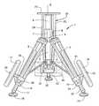
- FIG. 1provides an operative front view of a tripod erected and readied for application with instrumentation for use for surveying or laser tracking purposes;
- FIG. 2provides a side view of the tripod, collapsed, handle extended, and readied for usage as a cart or dolly.
- the tripodas usual, includes three legs, 2 - 4 , which are usually pivotally mounted to a pivot plate 5 .
- the pivot plateincludes a center post 6 that elevates upwardly, and is telescopically formed with its column 7 , so that the post 6 can be elevated, or lowered, within the center sleeve or column 7 , and then fastened in position by tightening of the fastener 8 as known in the art.
- the upper end of the center posthas a formed plate 9 and it is upon this plate that the theodolite, laser tracker, transit, or other instrumentation may be applied, when readied for usage and application.
- the tri-legs 2 - 4are usually designed to further function as pivotal legs, as identified, and at their bottom end includes sleeves, as at 10 , so the lower extendable legs 11 - 13 can be extended, to increase the height of the tripod, and then its fasteners 14 may be secured, to fix the adjusted lengthened legs into their set position.
- the bottom of each legwill have a base 15 in order to provide for stable mounting of the tripod upon a surface, even uneven surfaces, when it is set up for usage.
- the added accessories of this particular inventionare threefold, the addition of larger wheels 16 and 17 , bearing mounted to their wheel shafts 18 and 19 , and secured by their wheel axle 20 and 21 , to allow for the wheels to freely turn about their axles, when used.
- the wheel shafts 18 and 19are integrally formed with the sleeves 10 , and extend laterally outwardly therefrom, as can be readily noted.
- the wheelsWhen the tripod is adjusted, and collapse after usage, the wheels will be disposed for riding upon the ground, and allow the entire tripod assembly to be moved as a dolly, or cart, for ease of its conveyance, and to carry other equipment as to be identified hereinafter.
- the second aspect of this inventionis the incorporation of a handle 22 , which includes, in this particular instance, a pair of vertical shafts 23 and 24 , and having a cross bar 25 provided thereabove, to function as a handle to allow the tripod to be slanted forwardly to allow its wheels 16 and 17 to ride upon the surface, and to convey the entire instrument in the manner as previously described.
- the handle shafts 23 and 24are extended through the pivot plate 5 , and likewise, can be secured or fastened by means of any type of fastener (not showing) similar to the type of fasteners as shown at 14 , but in this particular instance, to allow the handle to be fixed in place, when used.
- the handle 22is arranged slightly forwardly of the center post 7 in order to furnish clearance for the hand when the handle is to be gripped, for movement of the tripod.
- the third aspect of this inventionis the inclusion of a support platform or shelve 26 , provided affixed to the back leg 4 of the tripod, and this will function as a means for furnishing a location where items may be arranged, fastened in place, to further aid in their conveyance during or after usage.
- FIG. 2shows the location of the support platform 26 , and it includes a base shelf 27 , and an upright support 28 that can accommodate the location of the equipment thereon.
- support platform 26is shown as an angled structure, it could just as likely be a basket, whether it be a wire basket, or the like, a box, or any other structure into which equipment may locate, during transit.
- other forms of straps or fastening meansmay be included for securement of the equipment thereon, as it is moved over a surface of the plant, outdoors upon the ground, or at other locations.
- the support platform 27is generally arranged at the same level as the bottom 29 of the wheels, so that as the tripod 1 is collapsed, it has a three point contact with the surface, in other words, the two wheels, and the support platform 27 , to assure that the tripod will remain erect, even when collapsed into its non-usable but conveyable condition, as noted.
- the wheels 16 and 17 of the accessorized tripoddo have some size, in order to provide clearance for the wheels to ride upon the ground, particularly when the lower legs 12 of the tripod telescope up into their upper legs 2 and 3 , to assure that the tripod can be moved upon its wheels, when shifted to a new location.
- these wheelsmay be anywhere from approximately 1 foot to 2 feet or slightly greater in diameter, to provide adequate clearance for the transit to be moved, when tilted forwardly, when used as a dolly. Small bicycle wheels may be useful for this purpose.
- the various equipmentmay be added onto the angled platform 26 , in preparation for usage.
Landscapes
- Engineering & Computer Science (AREA)
- General Engineering & Computer Science (AREA)
- Mechanical Engineering (AREA)
- Chemical & Material Sciences (AREA)
- Combustion & Propulsion (AREA)
- Transportation (AREA)
- Handcart (AREA)
Abstract
Description
Claims (10)
Priority Applications (1)
| Application Number | Priority Date | Filing Date | Title |
|---|---|---|---|
| US14/756,833US9557001B2 (en) | 2014-11-07 | 2015-10-20 | Combination portable industrial/survey instrument stand with conveyance capacities |
Applications Claiming Priority (2)
| Application Number | Priority Date | Filing Date | Title |
|---|---|---|---|
| US201462123113P | 2014-11-07 | 2014-11-07 | |
| US14/756,833US9557001B2 (en) | 2014-11-07 | 2015-10-20 | Combination portable industrial/survey instrument stand with conveyance capacities |
Publications (2)
| Publication Number | Publication Date |
|---|---|
| US20160131303A1 US20160131303A1 (en) | 2016-05-12 |
| US9557001B2true US9557001B2 (en) | 2017-01-31 |
Family
ID=55911924
Family Applications (1)
| Application Number | Title | Priority Date | Filing Date |
|---|---|---|---|
| US14/756,833Expired - Fee RelatedUS9557001B2 (en) | 2014-11-07 | 2015-10-20 | Combination portable industrial/survey instrument stand with conveyance capacities |
Country Status (1)
| Country | Link |
|---|---|
| US (1) | US9557001B2 (en) |
Cited By (3)
| Publication number | Priority date | Publication date | Assignee | Title |
|---|---|---|---|---|
| CN108007373A (en)* | 2017-12-08 | 2018-05-08 | 中国矿业大学(北京) | A kind of three-dimensional laser measures hoistable platform |
| CN110067920A (en)* | 2019-05-05 | 2019-07-30 | 娄凤敏 | A kind of firm and accuracy controlling instrument of surveying and mapping auxiliary device |
| US11285572B2 (en)* | 2020-06-24 | 2022-03-29 | United States Of America As Represented By The Secretary Of The Air Force | Tripod jack inner cylinder removal tool |
Families Citing this family (25)
| Publication number | Priority date | Publication date | Assignee | Title |
|---|---|---|---|---|
| US9663130B2 (en)* | 2015-10-19 | 2017-05-30 | Thomas Powwarynn | Combination motorized wheeled vehicle and portable hand truck |
| US10679595B2 (en) | 2016-10-28 | 2020-06-09 | Sheldon LAVINEWAY | Apparatus for supporting musical instruments |
| CN106567226A (en)* | 2016-11-14 | 2017-04-19 | 青岛海尔洗衣机有限公司 | Movable support leg and household electrical appliance having same |
| TWI619630B (en)* | 2017-07-03 | 2018-04-01 | Base of bicycle hanger | |
| CN107367448B (en)* | 2017-07-11 | 2020-03-17 | 江苏伟斯动科技有限公司 | Environmental monitoring system for monitoring particulate pollution source in real time |
| CN110159890A (en)* | 2018-04-13 | 2019-08-23 | 日照职业技术学院 | One kind being used for construction engineering cost plotting board |
| CN110260131A (en)* | 2019-06-26 | 2019-09-20 | 黄河水利职业技术学院 | A kind of engineering mapping instrument of surveying and mapping support frame |
| CN110285816B (en)* | 2019-06-28 | 2023-12-12 | 航天东方红卫星有限公司 | High-precision attitude measurement system and method for small satellite on-satellite equipment |
| CN110788491A (en)* | 2019-10-10 | 2020-02-14 | 大连理工大学 | Laser cutting machine |
| CN110630859B (en)* | 2019-10-15 | 2020-12-04 | 江苏食品药品职业技术学院 | A smart city mapping instrument based on the Internet of Things |
| JP7745995B2 (en)* | 2020-02-13 | 2025-09-30 | 株式会社トプコン | Tripods and surveying equipment |
| JP7499038B2 (en)* | 2020-02-13 | 2024-06-13 | 株式会社トプコン | Tripods and surveying equipment |
| CN111207283A (en)* | 2020-02-18 | 2020-05-29 | 山东省物化探勘查院 | Adjustable on-spot mapping device that is used for real estate survey and drawing |
| CN112155322A (en)* | 2020-09-27 | 2021-01-01 | 国网山东省电力公司青州市供电公司 | GPS support table for measurement |
| US11306864B1 (en)* | 2021-07-12 | 2022-04-19 | Anders Hjelset | Mobile observatory |
| CN113446483B (en)* | 2021-08-30 | 2021-11-12 | 南通市金润市政工程有限公司 | Geological survey is with measuring distance device |
| CN114111744B (en)* | 2021-11-23 | 2023-07-18 | 山东省地质矿产勘查开发局第八地质大队(山东省第八地质矿产勘查院) | Engineering measurement is with portable range unit |
| CN217178014U (en)* | 2022-01-25 | 2022-08-12 | 深圳联合创达科技有限公司 | A combination tripod |
| CN114562661B (en)* | 2022-03-15 | 2023-06-30 | 李育坤 | Multifunctional mapping device for land resource management |
| CN114962870B (en)* | 2022-04-12 | 2023-12-05 | 北京电子工程总体研究所 | Balancing device |
| CN115355416B (en)* | 2022-09-02 | 2025-08-08 | 山东省煤田地质局物探测量队 | A high-precision positioning surveying instrument for engineering surveying and mapping |
| CN115355431B (en)* | 2022-10-18 | 2023-04-25 | 滨州伟业交通公路工程有限公司 | Highway engineering construction level |
| CN115930070B (en)* | 2022-12-31 | 2024-11-15 | 华能(浙江)能源开发有限公司玉环分公司 | A mobile fire monitoring device |
| CN116691528A (en)* | 2023-06-30 | 2023-09-05 | 中冶建工集团有限公司 | Vehicle-mounted anti-loosening RTK bracket |
| CN119826072B (en)* | 2025-03-14 | 2025-06-17 | 潍坊天盛地理信息有限公司 | Surveying and mapping device for planning homeland space |
Citations (38)
| Publication number | Priority date | Publication date | Assignee | Title |
|---|---|---|---|---|
| US215033A (en) | 1879-05-06 | Improvement in targets and target-stands | ||
| US366833A (en) | 1887-07-19 | Tripod stand | ||
| US664976A (en) | 1899-08-01 | 1901-01-01 | Jay K Sheffy | Camp-stool. |
| US2368740A (en) | 1942-06-20 | 1945-02-06 | Oscar C Blomgren | Stool |
| US2828097A (en) | 1954-03-29 | 1958-03-25 | Stuart F Faunce | Nursing bottle holder |
| US2899204A (en) | 1959-08-11 | Portable target stand | ||
| US2990764A (en)* | 1960-08-19 | 1961-07-04 | Hal L Wilder | Combined camera support, cart and step ladder |
| US3104889A (en)* | 1963-09-24 | branch | ||
| US3121556A (en)* | 1961-11-02 | 1964-02-18 | Oliver H Faulkner | Airplane jack assembly with spring compressor |
| US3137522A (en) | 1962-07-13 | 1964-06-16 | Verne A Smith | Collapsible picnic table |
| US3667773A (en)* | 1970-11-17 | 1972-06-06 | Donald J Hess | Surveyor field tripod |
| US3826513A (en)* | 1973-11-29 | 1974-07-30 | L Wolf | Tripod carrier |
| US3863945A (en)* | 1973-09-04 | 1975-02-04 | Diane M Dunstan | Wheel unit for attachment to a tripod |
| US4120280A (en) | 1977-03-14 | 1978-10-17 | Harold L. Iverson | Adjustable grill device |
| US4253546A (en)* | 1978-05-15 | 1981-03-03 | Taichi Uchida | Hand truck |
| US4423849A (en) | 1982-06-14 | 1984-01-03 | Henry M. Kramer | Self-supporting structure |
| US4494626A (en)* | 1982-11-12 | 1985-01-22 | Harper, Truck, Inc. | Combination stepladder and hand truck apparatus |
| US4717108A (en) | 1986-11-06 | 1988-01-05 | Liedle William O | Temporary electrical service support system including novel self-contained bracket member |
| US4852836A (en)* | 1987-10-22 | 1989-08-01 | Michio Kawazoe | Tripod |
| US5029795A (en) | 1989-08-11 | 1991-07-09 | Dexter Ronald P | Camera support stand |
| US5145133A (en) | 1991-04-29 | 1992-09-08 | France Robert W | Target holder |
| US5401043A (en)* | 1993-10-25 | 1995-03-28 | Myron; Gordon D. | Collapsible cart |
| US5836595A (en)* | 1996-03-28 | 1998-11-17 | Brice; John Nigel | Combination stepladder/handtruck apparatus |
| US6007031A (en)* | 1997-06-13 | 1999-12-28 | Tang; Larry G. | Golf bag stand and stroller |
| US6471220B1 (en)* | 2000-06-13 | 2002-10-29 | Emerson Electric Co. | Cart and stand for supporting and transporting metal working apparatus |
| US7172512B2 (en) | 2004-11-17 | 2007-02-06 | Be Be | Frame support member for recreational swing |
| US20080197587A1 (en)* | 2007-02-15 | 2008-08-21 | Mark Adam Nowak | Combination cart and stand device |
| US7581703B1 (en) | 2007-03-05 | 2009-09-01 | David Harold Coleman | Radial tripod stabilizer |
| US7604207B2 (en)* | 2002-03-19 | 2009-10-20 | Faro Technologies, Inc. | Tripod and method |
| US7614628B2 (en)* | 2004-06-22 | 2009-11-10 | Ezm, Inc. | Convertible carrying case systems and collapsible wheeled carts for carrying cases |
| US7946588B1 (en) | 2010-03-04 | 2011-05-24 | James Glen Hockman | Target retrieval system |
| US8714508B1 (en) | 2006-02-09 | 2014-05-06 | Primos, Inc. | Telescoping support stand apparatus |
| US8720895B2 (en) | 2011-12-13 | 2014-05-13 | Bradley MATTHIS | Portable archery target support |
| US8780263B2 (en) | 2010-01-04 | 2014-07-15 | The Tiffen Company Llc | Balanced mounting arrangement for, and method of, steadily supporting a motion-sensitive, image capture device |
| US8820693B1 (en) | 2006-02-09 | 2014-09-02 | Primos, Inc. | Telescoping support stand apparatus |
| US8836508B2 (en) | 2012-02-03 | 2014-09-16 | H4 Engineering, Inc. | Apparatus and method for securing a portable electronic device |
| US8858097B2 (en) | 2011-04-08 | 2014-10-14 | Daymen Us, Inc. | Miniature ball tripod |
| US9278703B1 (en)* | 2014-11-06 | 2016-03-08 | Edmund E. Hollub, IV | Apparatus having a hand truck configuration and a tripod configuration |
- 2015
- 2015-10-20USUS14/756,833patent/US9557001B2/ennot_activeExpired - Fee Related
Patent Citations (38)
| Publication number | Priority date | Publication date | Assignee | Title |
|---|---|---|---|---|
| US215033A (en) | 1879-05-06 | Improvement in targets and target-stands | ||
| US366833A (en) | 1887-07-19 | Tripod stand | ||
| US2899204A (en) | 1959-08-11 | Portable target stand | ||
| US3104889A (en)* | 1963-09-24 | branch | ||
| US664976A (en) | 1899-08-01 | 1901-01-01 | Jay K Sheffy | Camp-stool. |
| US2368740A (en) | 1942-06-20 | 1945-02-06 | Oscar C Blomgren | Stool |
| US2828097A (en) | 1954-03-29 | 1958-03-25 | Stuart F Faunce | Nursing bottle holder |
| US2990764A (en)* | 1960-08-19 | 1961-07-04 | Hal L Wilder | Combined camera support, cart and step ladder |
| US3121556A (en)* | 1961-11-02 | 1964-02-18 | Oliver H Faulkner | Airplane jack assembly with spring compressor |
| US3137522A (en) | 1962-07-13 | 1964-06-16 | Verne A Smith | Collapsible picnic table |
| US3667773A (en)* | 1970-11-17 | 1972-06-06 | Donald J Hess | Surveyor field tripod |
| US3863945A (en)* | 1973-09-04 | 1975-02-04 | Diane M Dunstan | Wheel unit for attachment to a tripod |
| US3826513A (en)* | 1973-11-29 | 1974-07-30 | L Wolf | Tripod carrier |
| US4120280A (en) | 1977-03-14 | 1978-10-17 | Harold L. Iverson | Adjustable grill device |
| US4253546A (en)* | 1978-05-15 | 1981-03-03 | Taichi Uchida | Hand truck |
| US4423849A (en) | 1982-06-14 | 1984-01-03 | Henry M. Kramer | Self-supporting structure |
| US4494626A (en)* | 1982-11-12 | 1985-01-22 | Harper, Truck, Inc. | Combination stepladder and hand truck apparatus |
| US4717108A (en) | 1986-11-06 | 1988-01-05 | Liedle William O | Temporary electrical service support system including novel self-contained bracket member |
| US4852836A (en)* | 1987-10-22 | 1989-08-01 | Michio Kawazoe | Tripod |
| US5029795A (en) | 1989-08-11 | 1991-07-09 | Dexter Ronald P | Camera support stand |
| US5145133A (en) | 1991-04-29 | 1992-09-08 | France Robert W | Target holder |
| US5401043A (en)* | 1993-10-25 | 1995-03-28 | Myron; Gordon D. | Collapsible cart |
| US5836595A (en)* | 1996-03-28 | 1998-11-17 | Brice; John Nigel | Combination stepladder/handtruck apparatus |
| US6007031A (en)* | 1997-06-13 | 1999-12-28 | Tang; Larry G. | Golf bag stand and stroller |
| US6471220B1 (en)* | 2000-06-13 | 2002-10-29 | Emerson Electric Co. | Cart and stand for supporting and transporting metal working apparatus |
| US7604207B2 (en)* | 2002-03-19 | 2009-10-20 | Faro Technologies, Inc. | Tripod and method |
| US7614628B2 (en)* | 2004-06-22 | 2009-11-10 | Ezm, Inc. | Convertible carrying case systems and collapsible wheeled carts for carrying cases |
| US7172512B2 (en) | 2004-11-17 | 2007-02-06 | Be Be | Frame support member for recreational swing |
| US8714508B1 (en) | 2006-02-09 | 2014-05-06 | Primos, Inc. | Telescoping support stand apparatus |
| US8820693B1 (en) | 2006-02-09 | 2014-09-02 | Primos, Inc. | Telescoping support stand apparatus |
| US20080197587A1 (en)* | 2007-02-15 | 2008-08-21 | Mark Adam Nowak | Combination cart and stand device |
| US7581703B1 (en) | 2007-03-05 | 2009-09-01 | David Harold Coleman | Radial tripod stabilizer |
| US8780263B2 (en) | 2010-01-04 | 2014-07-15 | The Tiffen Company Llc | Balanced mounting arrangement for, and method of, steadily supporting a motion-sensitive, image capture device |
| US7946588B1 (en) | 2010-03-04 | 2011-05-24 | James Glen Hockman | Target retrieval system |
| US8858097B2 (en) | 2011-04-08 | 2014-10-14 | Daymen Us, Inc. | Miniature ball tripod |
| US8720895B2 (en) | 2011-12-13 | 2014-05-13 | Bradley MATTHIS | Portable archery target support |
| US8836508B2 (en) | 2012-02-03 | 2014-09-16 | H4 Engineering, Inc. | Apparatus and method for securing a portable electronic device |
| US9278703B1 (en)* | 2014-11-06 | 2016-03-08 | Edmund E. Hollub, IV | Apparatus having a hand truck configuration and a tripod configuration |
Cited By (6)
| Publication number | Priority date | Publication date | Assignee | Title |
|---|---|---|---|---|
| CN108007373A (en)* | 2017-12-08 | 2018-05-08 | 中国矿业大学(北京) | A kind of three-dimensional laser measures hoistable platform |
| CN108007373B (en)* | 2017-12-08 | 2019-08-27 | 中国矿业大学(北京) | A three-dimensional laser measurement lifting platform |
| CN110067920A (en)* | 2019-05-05 | 2019-07-30 | 娄凤敏 | A kind of firm and accuracy controlling instrument of surveying and mapping auxiliary device |
| US11285572B2 (en)* | 2020-06-24 | 2022-03-29 | United States Of America As Represented By The Secretary Of The Air Force | Tripod jack inner cylinder removal tool |
| US20220168855A1 (en)* | 2020-06-24 | 2022-06-02 | Government of the United States, as Represented by the Secretary of the Air Forece | Tripod jack inner cylinder removal tool |
| US11471985B2 (en)* | 2020-06-24 | 2022-10-18 | United States Of America As Represented By The Secretary Of The Air Force | Tripod jack inner cylinder removal tool |
Also Published As
| Publication number | Publication date |
|---|---|
| US20160131303A1 (en) | 2016-05-12 |
Similar Documents
| Publication | Publication Date | Title |
|---|---|---|
| US9557001B2 (en) | Combination portable industrial/survey instrument stand with conveyance capacities | |
| CN100400958C (en) | Tripod and how to use it | |
| US20220299159A1 (en) | Modular utility system | |
| US7431313B1 (en) | Portable tool storage apparatus | |
| US8328173B1 (en) | Support stand system for automobile parts | |
| US9622597B2 (en) | Garment rack | |
| US7500681B2 (en) | Collapsible carrying trolley | |
| US8104778B1 (en) | Dual purpose wheeled cart apparatus | |
| US20190111987A1 (en) | Two wheel golf cart with bag holder kickstand | |
| US20190249821A1 (en) | Portable stable tripod for photographic equipment | |
| US11028962B1 (en) | Collapsing jack stand | |
| US10562463B1 (en) | Vehicle load carrier with integrated handling wheels | |
| US20090145338A1 (en) | Portable rapid work station | |
| US9283973B1 (en) | Hand-truck pouring stand | |
| CN216479910U (en) | Adjusting support for geographic surveying and mapping | |
| US6848718B2 (en) | Ski caddy having means for utilizing ski poles as a support | |
| CN110785343A (en) | System for rolling folding bicycle | |
| US9145095B2 (en) | Bicycle support apparatus and method | |
| US8882064B2 (en) | Collapsible stand assembly | |
| US20050092213A1 (en) | Portable plan table for use with trailer hitch | |
| US2775465A (en) | Portable cart | |
| US9586128B2 (en) | Collapsible ski caddy | |
| US20190337546A1 (en) | Dolly for transporting a portable shelter | |
| US20090152412A1 (en) | Instrument stand | |
| US20060022005A1 (en) | EZ carry side basket |
Legal Events
| Date | Code | Title | Description |
|---|---|---|---|
| AS | Assignment | Owner name:HUBBS MACHINE & MANUFACTURING, INC., MISSOURI Free format text:ASSIGNMENT OF ASSIGNORS INTEREST;ASSIGNOR:HUBBS, WILLIAM O.;REEL/FRAME:041085/0805 Effective date:20160927 | |
| STCF | Information on status: patent grant | Free format text:PATENTED CASE | |
| AS | Assignment | Owner name:BLACK KNIGHT ENTERPRISES, LLC, MISSOURI Free format text:ASSIGNMENT OF ASSIGNORS INTEREST;ASSIGNOR:HUBBS MACHINE & MANUFACTURING, INC.;REEL/FRAME:050196/0920 Effective date:20190531 | |
| FEPP | Fee payment procedure | Free format text:MAINTENANCE FEE REMINDER MAILED (ORIGINAL EVENT CODE: REM.); ENTITY STATUS OF PATENT OWNER: SMALL ENTITY | |
| FEPP | Fee payment procedure | Free format text:SURCHARGE FOR LATE PAYMENT, SMALL ENTITY (ORIGINAL EVENT CODE: M2554); ENTITY STATUS OF PATENT OWNER: SMALL ENTITY | |
| MAFP | Maintenance fee payment | Free format text:PAYMENT OF MAINTENANCE FEE, 4TH YR, SMALL ENTITY (ORIGINAL EVENT CODE: M2551); ENTITY STATUS OF PATENT OWNER: SMALL ENTITY Year of fee payment:4 | |
| FEPP | Fee payment procedure | Free format text:MAINTENANCE FEE REMINDER MAILED (ORIGINAL EVENT CODE: REM.); ENTITY STATUS OF PATENT OWNER: SMALL ENTITY | |
| LAPS | Lapse for failure to pay maintenance fees | Free format text:PATENT EXPIRED FOR FAILURE TO PAY MAINTENANCE FEES (ORIGINAL EVENT CODE: EXP.); ENTITY STATUS OF PATENT OWNER: SMALL ENTITY | |
| STCH | Information on status: patent discontinuation | Free format text:PATENT EXPIRED DUE TO NONPAYMENT OF MAINTENANCE FEES UNDER 37 CFR 1.362 | |
| FP | Lapsed due to failure to pay maintenance fee | Effective date:20250131 |