US9555429B2 - Method and device for indicating future need for product replacement of random-use dispensing - Google Patents
Method and device for indicating future need for product replacement of random-use dispensingDownload PDFInfo
- Publication number
- US9555429B2 US9555429B2US12/425,444US42544409AUS9555429B2US 9555429 B2US9555429 B2US 9555429B2US 42544409 AUS42544409 AUS 42544409AUS 9555429 B2US9555429 B2US 9555429B2
- Authority
- US
- United States
- Prior art keywords
- value
- controller
- refill container
- dispenser
- coupled
- Prior art date
- Legal status (The legal status is an assumption and is not a legal conclusion. Google has not performed a legal analysis and makes no representation as to the accuracy of the status listed.)
- Active, expires
Links
Images


Classifications
- G—PHYSICS
- G01—MEASURING; TESTING
- G01F—MEASURING VOLUME, VOLUME FLOW, MASS FLOW OR LIQUID LEVEL; METERING BY VOLUME
- G01F17/00—Methods or apparatus for determining the capacity of containers or cavities, or the volume of solid bodies
- A—HUMAN NECESSITIES
- A47—FURNITURE; DOMESTIC ARTICLES OR APPLIANCES; COFFEE MILLS; SPICE MILLS; SUCTION CLEANERS IN GENERAL
- A47K—SANITARY EQUIPMENT NOT OTHERWISE PROVIDED FOR; TOILET ACCESSORIES
- A47K5/00—Holders or dispensers for soap, toothpaste, or the like
- A47K5/06—Dispensers for soap
- A47K5/12—Dispensers for soap for liquid or pasty soap
- B—PERFORMING OPERATIONS; TRANSPORTING
- B05—SPRAYING OR ATOMISING IN GENERAL; APPLYING FLUENT MATERIALS TO SURFACES, IN GENERAL
- B05B—SPRAYING APPARATUS; ATOMISING APPARATUS; NOZZLES
- B05B11/00—Single-unit hand-held apparatus in which flow of contents is produced by the muscular force of the operator at the moment of use
- B05B11/01—Single-unit hand-held apparatus in which flow of contents is produced by the muscular force of the operator at the moment of use characterised by the means producing the flow
- B05B11/10—Pump arrangements for transferring the contents from the container to a pump chamber by a sucking effect and forcing the contents out through the dispensing nozzle
- B05B11/1042—Components or details
- B05B11/108—Means for counting the number of dispensing strokes
- B05B11/30—
- B—PERFORMING OPERATIONS; TRANSPORTING
- B05—SPRAYING OR ATOMISING IN GENERAL; APPLYING FLUENT MATERIALS TO SURFACES, IN GENERAL
- B05B—SPRAYING APPARATUS; ATOMISING APPARATUS; NOZZLES
- B05B12/00—Arrangements for controlling delivery; Arrangements for controlling the spray area
- B05B12/004—Arrangements for controlling delivery; Arrangements for controlling the spray area comprising sensors for monitoring the delivery, e.g. by displaying the sensed value or generating an alarm
- B05B12/006—Pressure or flow rate sensors
- B05B12/008—Pressure or flow rate sensors integrated in or attached to a discharge apparatus, e.g. a spray gun
- B—PERFORMING OPERATIONS; TRANSPORTING
- B05—SPRAYING OR ATOMISING IN GENERAL; APPLYING FLUENT MATERIALS TO SURFACES, IN GENERAL
- B05B—SPRAYING APPARATUS; ATOMISING APPARATUS; NOZZLES
- B05B12/00—Arrangements for controlling delivery; Arrangements for controlling the spray area
- B05B12/08—Arrangements for controlling delivery; Arrangements for controlling the spray area responsive to condition of liquid or other fluent material to be discharged, of ambient medium or of target ; responsive to condition of spray devices or of supply means, e.g. pipes, pumps or their drive means
- B05B12/082—Arrangements for controlling delivery; Arrangements for controlling the spray area responsive to condition of liquid or other fluent material to be discharged, of ambient medium or of target ; responsive to condition of spray devices or of supply means, e.g. pipes, pumps or their drive means responsive to a condition of the discharged jet or spray, e.g. to jet shape, spray pattern or droplet size
- G—PHYSICS
- G01—MEASURING; TESTING
- G01F—MEASURING VOLUME, VOLUME FLOW, MASS FLOW OR LIQUID LEVEL; METERING BY VOLUME
- G01F13/00—Apparatus for measuring by volume and delivering fluids or fluent solid materials, not provided for in the preceding groups
- G—PHYSICS
- G01—MEASURING; TESTING
- G01F—MEASURING VOLUME, VOLUME FLOW, MASS FLOW OR LIQUID LEVEL; METERING BY VOLUME
- G01F15/00—Details of, or accessories for, apparatus of groups G01F1/00 - G01F13/00 insofar as such details or appliances are not adapted to particular types of such apparatus
- G01F15/06—Indicating or recording devices
- G01F15/068—Indicating or recording devices with electrical means
- A—HUMAN NECESSITIES
- A47—FURNITURE; DOMESTIC ARTICLES OR APPLIANCES; COFFEE MILLS; SPICE MILLS; SUCTION CLEANERS IN GENERAL
- A47K—SANITARY EQUIPMENT NOT OTHERWISE PROVIDED FOR; TOILET ACCESSORIES
- A47K5/00—Holders or dispensers for soap, toothpaste, or the like
- A47K5/06—Dispensers for soap
- A47K5/12—Dispensers for soap for liquid or pasty soap
- A47K5/1217—Electrical control means for the dispensing mechanism
- B—PERFORMING OPERATIONS; TRANSPORTING
- B05—SPRAYING OR ATOMISING IN GENERAL; APPLYING FLUENT MATERIALS TO SURFACES, IN GENERAL
- B05B—SPRAYING APPARATUS; ATOMISING APPARATUS; NOZZLES
- B05B11/00—Single-unit hand-held apparatus in which flow of contents is produced by the muscular force of the operator at the moment of use
- B05B11/01—Single-unit hand-held apparatus in which flow of contents is produced by the muscular force of the operator at the moment of use characterised by the means producing the flow
- B05B11/10—Pump arrangements for transferring the contents from the container to a pump chamber by a sucking effect and forcing the contents out through the dispensing nozzle
- B05B11/1042—Components or details
- B05B11/1052—Actuation means
- B05B11/1053—Actuation means combined with means, other than pressure, for automatically opening a valve during actuation; combined with means for automatically removing closures or covers from the discharge nozzle during actuation
- B05B11/3053—
- B05B11/308—
- B—PERFORMING OPERATIONS; TRANSPORTING
- B05—SPRAYING OR ATOMISING IN GENERAL; APPLYING FLUENT MATERIALS TO SURFACES, IN GENERAL
- B05B—SPRAYING APPARATUS; ATOMISING APPARATUS; NOZZLES
- B05B12/00—Arrangements for controlling delivery; Arrangements for controlling the spray area
- B05B12/08—Arrangements for controlling delivery; Arrangements for controlling the spray area responsive to condition of liquid or other fluent material to be discharged, of ambient medium or of target ; responsive to condition of spray devices or of supply means, e.g. pipes, pumps or their drive means
- B05B12/081—Arrangements for controlling delivery; Arrangements for controlling the spray area responsive to condition of liquid or other fluent material to be discharged, of ambient medium or of target ; responsive to condition of spray devices or of supply means, e.g. pipes, pumps or their drive means responsive to the weight of a reservoir or container for liquid or other fluent material; responsive to level or volume of liquid or other fluent material in a reservoir or container
Definitions
- the inventionrelates to the field of dispensing indication systems. More particularly, the invention relates to methods and devices for inventory control and efficient route planning for the supply and maintenance of dispensers. More specifically, the invention relates to monitoring devices and methods for indicating whether product in a dispenser will require replacement prior to the next scheduled service.
- Dispenser indicators for low productare widely known in the art.
- known dispensersprovide indication by fixed recordings of information.
- a dispenserwill incorporate a counter or sensor that triggers a warning based from a constant value.
- One disadvantage of these prior-art devicesis that they may trigger a warning only after complete consumption of the product.
- Another disadvantage inherent to these prior-art devicesis the inability to predict whether the dispenser requires replacement resulting from the dispenser's varying usage.
- Dial et al.teaches an approach to calculate the dispensing of a predetermined amount of a material.
- the '074 patentteaches a method wherein a dispensing score representative of the time of operation of a dispenser multiplied by a factor representative of the frequency or intensity of dispensing is calculated, and the calculated dispensing score is compared with a predetermined total score.
- the '074 patentdiscloses an alarm when the dispensing score is greater than the predetermined total score.
- the '074 patentdoes not indicate when the dispenser is almost out of fluid but triggers a warning when it is believed that complete consumption has occurred.
- the frequencyis not determined from random use but is controlled by a preset frequency. Therefore, there is a need to predict and provide warning of the future emptying of a random-use product dispenser.
- Yet another aspect of the present inventionis to provide a device adaptable to a variety of different product refills that determines the need of product replacement based on product quantity, next scheduled service, and random usage (to prevent complete emptying of product prior to next scheduled service).
- a further aspect of the present inventionis to provide a device with an adjustable service interval input that determines the need of product replacement based on product quantity, next scheduled service, and random usage (to prevent complete emptying of product).
- Yet another aspect of the present inventionis to provide a method for indicating when to replace material in a dispenser setting an activation count to a number representative of the amount of dispenses remaining, setting a service interval for the dispenser over a number of units of time, decrementing said activation count upon each activation of the dispenser, calculating a running average of material usage representative of one unit of time, comparing said activation count with the product of said running average and said service interval, and indicating the dispenser requires refilling when said product is greater than said activation count.
- a further aspect of the present inventionis to provide a dispenser for dispensing product comprising an activation count setting means for setting an activation count; a means for setting a service interval for allowing entry of a service interval representative of the number of units of time before next service; a dispensing mechanism; an indication means; a controller; and a switch associated with said dispensing mechanism that generates a voltage received by said controller that decrements an activation count associated with the number of dispenses of material, wherein said controller compares said activation count with the product of said service interval and average of material usage representative of one unit of time, said controller sending a signal to said indication means when said product is greater than said activation count.
- Yet another aspect of the present inventionis to provide a dispenser to dispense material from a refill container
- a controllermaintaining an initial quantity value defining the amount of material carried by the refill container; an actuator coupled to said controller; a pump adapted to be operatively coupled to the refill container, said pump also coupled to said controller, wherein when said actuator is engaged, said pump dispenses an amount of said material from the refill container according to a shot size value maintained by said controller, said controller updating a cumulative usage value maintained thereby by said shot size value, and generating a current quantity value based on the difference between said initial quantity value and said cumulative usage value; a timer associated with said controller to update a timed count value, said timer initiated when said refill container is coupled to said pump; and an indicator coupled to said controller, wherein said controller generates an average usage value based on said cumulative usage value and said timed count value, whereupon said controller generates a service interval value based on said current quantity value and said average usage value, said service interval value displayed by said indicator.
- a further aspect of the present inventionis to provide a dispenser comprising a refill container carrying an initial amount of material; a controller configured to maintain an initial quantity value defined by said initial amount of material maintained by said refill container; an actuator coupled to said controller; a pump coupled to said controller and to said refill container, wherein when said actuator is engaged, said pump dispenses an amount of said material from said refill container according to a shot size value maintained by said controller, said controller updating a cumulative usage value maintained thereby by said shot size value, and generating a current quantity value based on the difference between said initial quantity value and said cumulative usage value; a timer coupled to said controller to update a timed count value, said timer initiated when said refill container is coupled to said pump; and an indicator coupled to said controller, wherein said controller generates an average usage value based on said cumulative usage value and said timed count value, whereupon said controller generates a service interval value based on said current quantity value and said average usage value, said service interval value displayed by said indicator.
- Yet another aspect of the present inventionis to provide a method of determining the remaining service interval of a refill container comprising providing a dispenser to dispense material from a refill container, said refill container having an initial amount of said material; providing an indicator maintained by said dispenser; dispensing material from said refill container in a predetermined shot size; monitoring the total dispensement of said material from said initial amount; generating an average usage value based on the total dispensement of said material over a period of time; generating a service interval value indicating the remaining durational operating life of said refill container based on the remaining quantity of said material and said average usage value; and indicating said service interval value via said indicator.
- a further aspect of the present inventionis to provide a dispenser to dispense material from a refill container
- a controllermaintaining an initial quantity value defining the amount of material carried by the refill container, said controller including a timer that maintains a timed count value that is updated at a predetermined interval; an indicator coupled to said controller; an actuator coupled to said controller; a pump coupled to said controller and adapted to be operatively coupled to the refill container, said controller initiating said timer when the refill container is coupled to said pump, such that when said actuator is engaged, said pump dispenses an amount of material from the refill container according to a predetermined shot size value and said controller updates a cumulative usage value maintained thereby by said shot size value; wherein said controller calculates an average usage value from the division of said cumulative usage value and said timed count value, said controller calculating a service interval from the division of said average usage value and said timed count value that is communicated via said indicator.
- Yet another aspect of the present inventionis to provide a dispenser comprising a refill container carrying an initial amount of material; a controller configured to maintain an initial quantity value defined by said initial amount of material maintained by the refill container, said controller including a timer that maintains a timed count value that is updated at a predetermined interval; an indicator coupled to said controller; an actuator coupled to said controller; a pump coupled to said controller and adapted to be operatively coupled to the refill container, said controller initiating said timer when the refill container is coupled to said pump, such that when said actuator is engaged, said pump dispenses an amount of material from the refill container according to a predetermined shot size value and said controller updates a cumulative usage value maintained thereby by said shot size value, wherein said controller calculates an average usage value from the division of said cumulative usage value and said timed count value, said controller calculating a service interval from the division of said initial quantity value by said average usage value that is communicated via said indicator.
- a further aspect of the present inventionis to provide a method of determining the remaining service interval of a refill container comprising providing a dispenser to dispense material from a refill container, said refill container having an initial amount of said material; providing an indicator maintained by said dispenser; dispensing material from said refill container; monitoring the total dispensement of said material; generating an average usage value based on the total dispensement of said material over a period of time; generating a service interval value indicating the remaining durational operating life of said refill container based on the initial quantity of said material divided by said average usage value; and indicating said service interval value via said indicator.
- FIG. 1is a schematic of a dispenser in accordance with the concepts of the present invention
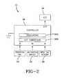
- FIG. 2is a detailed schematic of the dispenser showing a controller, an RFID tag reader, a potentiometer, and an LED according to the present invention
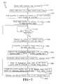
- FIG. 3is a flowchart of the operational steps for triggering the indicator of the present invention.
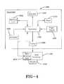
- FIG. 4is a block diagram showing a dispenser with an integrated service interval indicator in accordance with the concepts of the present invention.
- FIG. 5is a block diagram showing another embodiment of the dispenser that provides a keypad to enter the capacity of a new refill container in accordance with the concepts of the present invention
- FIG. 6is a schematic view showing an indicator used to display a service interval in accordance with the concepts of the present invention.
- FIG. 7is a flow diagram showing the operational steps taken by the dispenser when calculating a service interval value for display by the dispenser in accordance with the concepts of the present invention.
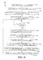
- FIG. 8is a flow diagram showing the operational steps taken by the dispenser when calculating an alternative service interval value for display by the dispenser in accordance with the concepts of the present invention.
- a dispenser made in accordance with the inventionis designated generally by the numeral 10 .
- the dispenserincludes a dispenser housing structure of widely-known dispensers, designated generally by the numeral 12 .
- the dispenser housing 12may be a wall or counter-mount unit or can be a freestanding unit disposed on a countertop or the like.
- the dispenser described hereinis used for dispensing fluids, such as soaps and other liquids, but it will be appreciated that other products could be dispensed, such as paper, tablets, or any flowable material.
- the dispenser housing 12typically includes a cartridge of liquid product 14 positioned above and in communication with a dispensing nozzle 16 , with an appropriate pump or other dispensing mechanism 18 interposed therebetween.
- the dispensing mechanism 18is configured to dispense a preset amount of liquid upon each dispensing cycle.
- the dispensing mechanism 18is controlled by an actuating mechanism 20 , such as a motor, solenoid, plunger or the like.
- the mechanism 20is energized upon the detection of an object, such as a user's hands, positioned beneath the dispensing nozzle 16 .
- the mechanism 20is not limited to a touch-free device and can employ any means of actuation readily known in the art.
- an indication circuitdesignated generally by the numeral 21 , includes a duration dial 22 , which allows an end user to select a service interval representative of the total amount of time before the next scheduled service.
- the duration dial 22consists of a potentiometer 24 and knob 26 representative of the amount of time associated with potentiometer 24 .
- the service intervalis based on a selected number of weeks; however it should be readily apparent that the service interval may represent any time interval. In another embodiment, the service interval may be preprogrammed to an arbitrary value, such as four weeks.
- the indication circuit 21also includes a radio frequency identification (“RFID”) tag reader 28 that communicates with an RFID tag 30 included on the refill cartridge 14 .
- RFID tag 30includes an activation count, which will be further described below.
- the activation countcan be established by a variety of methods, including bar code technology, a resistor representative of the count positioned on the refill cartridge, or by an amount of product dial (potentiometer 31 ) that allows for manual entry by a service provider. Similar to the service-interval control, the activation count may also be preprogrammed to an arbitrary value representative to the size of the refill.
- the indication circuit 21includes an activation switch 32 associated with actuating mechanism 20 .
- the indication circuit 21provides an indication in the form of a light-emitting diode (LED) 34 that flashes (illuminates) when the cartridge of the dispenser is in need of replacement prior to the next service interval.
- the indicationis generated prior to complete depletion of the product and only when usage suggests the product will need to be refilled prior to the next service interval.
- the LED 34can be replaced with any warning, such as a buzzer, bulb, or any other device that would provide apparent indication to the service provider that the dispenser is in need of a replacement refill. It should also be noted that the LED 34 does not have to be positioned on dispenser 10 and can be located remotely.
- the indication circuit 21also includes a controller 36 , which receives data from duration dial 22 , the RFID tag reader 28 , and the activation switch 32 .
- Controller 36provides the necessary hardware, software, and memory to implement the functions of the control circuit and properly operate the dispenser 10 .
- the controller 36can read up to six different voltage settings provided by the potentiometer 24 for the service interval and can adjust the initial activation count provided by the RFID tag reader 28 .
- the controller 36processes the information provided from the above-stated inputs and determines whether to supply voltage to the LED 34 . In the preferred embodiment, the controller 36 will produce a signal to blink the LED 34 once every two seconds.
- the controller 36could be a microcontroller such as that manufactured by Zilog. Of course, controllers manufactured by others could be used.
- the controller 36may also include, among other components, multiple oscillators 36 A and an analog to digital converter 36 B. Generally, one of the multiple oscillators 36 A could be an internal oscillator, which, if properly enabled, may run continuously. Other oscillators may be used for other functions. Skilled artisans will appreciate that the controller 36 will operate in low-power modes when waiting for the activation switch to be activated and when not performing calculations. Skilled artisans will also appreciate that accurate timekeeping can be maintained by using an external watch crystal or by calibrating the controller's internal oscillator(s) 36 A to an external watch crystal.
- the converter 36 Bis utilized by the controller 36 to receive analog voltage signals generated by the duration dial 22 .
- the converter 36 Bmay be in the form of a comparator or an analog-to-digital converter.
- the controller 36stores weekly usage and activation count to a non-volatile storage once per day to prevent loss of data during battery replacement. Contemporaneously, the controller 36 averages the daily counts into the weekly average. After servicing the dispenser, the activation count may be reset to an initial value through a number of ways, including a manual reset switch, a unique serial number on the RFID tag, or the like.
- the operational process performed by the controller 36 for indicationis designated by the numeral 38 , as shown in FIG. 3 .
- the process 38has a start sequence at step 40 .
- the controller 36stores an activation count, which is provided by the RFID tag reader 28 .
- the activation countrepresents the total number of dispenses remaining in the cartridge 14 .
- controller 36stores the service interval in weeks, which is entered from the duration dial.
- controller 36monitors the activation switch 32 to determine whether the dispenser has been activated. When the controller 36 detects the dispenser has been activated, the controller 36 increments the daily count as shown in step 48 and then returns back to step 46 . It should be noted that the daily count is initially set to zero but remains in memory for a weekly average calculation, which will be further discussed below.
- step 50determines whether it is the end of the day.
- the controller 36determines whether the refill has been changed at step 52 .
- the controller 36either returns to step 42 when the controller 36 detects a signal indicating product replacement or returns to step 46 if replacement has not yet occurred.
- step 50the controller 36 proceeds to step 54 and subtracts a daily count from the activation count.
- step 56the controller 36 calculates a weekly average by evaluating the current daily count with the daily counts of the past six days. The weekly average can be calculated even after cartridge replacement because, as stated above, the daily count remains in memory after the service interval and the activation count have been reset.
- step 58the controller 36 compares the product of the weekly average and service interval to the activation count. If the product of the weekly average and service interval is less than the activation count, the controller 36 does not power light-emitting diode 34 , as shown in step 60 .
- the controller 36sends a signal to flash the LED 34 to indicate that the dispensing material will be consumed prior to the next scheduled service, as shown at step 62 . After step 62 , the controller 36 then returns to step 46 .
- FIGS. 4-8another embodiment of the present invention provides a dispenser 100 with an integrated service interval indicator.
- the dispenser 100as shown in FIGS. 4 and 5 , is configured to maintain a replaceable refill container 110 that carries a predetermined quantity of material, such as soap.
- a timer 120that is monitored by a controller 150 identifies the cumulative duration in which the refill container 110 has been placed into use. Using the cumulative duration value, the controller 150 identifies the average usage of the refill container 110 to compute a remaining service interval value or optimum service interval value that identifies the remaining duration in which the refill container 110 is anticipated to remain operable.
- the dispenser 100enables the individual charged with the replacement of the consumed or depleted refill containers to reduce the frequency by which they are monitored between their replacement, thereby saving time and resources.
- the time saved from the reduced monitoring frequencymay be used to check and monitor additional dispensers that could not normally be checked by that person.
- the dispenser 100includes the controller 150 that comprises the necessary hardware and/or software needed to carry out the functions to be discussed. Coupled to the controller 150 is a pump 200 that is in operative communication with the replaceable refill container 110 , which maintains a predetermined amount of material, such as soap. An actuator 230 coupled to the controller 150 initiates a dispensing cycle of a predetermined or metered amount of material from a nozzle 240 in accordance with a shot size value stored at a memory unit 300 .
- the actuator 230may comprise a manually-actuated button, lever, or other device that when physically engaged, initiates the dispensement of material.
- the dispenser 100may be configured to enable touch-free operation, such that the actuator 230 is configured as a proximity sensor, such as an IR (infrared) sensor, whereby the presence of the user's hand initiates the dispensing of material from the refill container 110 .
- the refill container 110may maintain any other suitable type of material, including but not limited to soap, sanitizer, lotion, or any other viscous, flowable, powder, granular substance or product. It also is foreseen that the dispensers 100 may be readily configured to dispense wipes, tablets, or other products.
- the memory unit 300is coupled to the controller 150 and comprises non-volatile memory (NVM), volatile memory, or a combination of both.
- NVMnon-volatile memory
- the memory unit 300may be removable from the dispenser 100 so that it can be remotely programmed with various data to be discussed and then reinserted at the dispenser 100 .
- the memory unit 300may be removed from the controller 150 , it may be made integral therewith as well.
- the memory unit 300may be configured to maintain a memory that is integral with the dispenser 100 or that is removable from the dispenser 100 .
- the timer 120is also coupled to the controller 150 .
- the timer 120is capable of identifying the amount of time that has elapsed since the refill container 220 was inserted into the dispenser 100 .
- the timer 120when the dispenser 100 is operational, the timer 120 generates a timed count value that is stored and updated at the memory unit 300 . While the timer 120 is shown as being a separate component, it may be integral with the controller 150 .
- a power supply 400is coupled to the controller 150 .
- the power supply 400may be configured to receive power from either a portable power source, such as a battery, or a mains power source, such as 120 VAC provided by a wall outlet.
- a visual and/or audible indicator 450is coupled to the controller 150 .
- the indicator 450comprises any suitable display or display element, such as an LED (light-emitting diode), LCD (liquid crystal display), speaker, or any other device that may provide visual indicia and/or audible prompts to indicate the remaining service interval for the refill container 220 .
- a LED maintained by the dispenser 100may generate two flashes to indicate that two weeks of product remains.
- the controller 150is required to ascertain an initial quantity value from the refill container 110 , which identifies the total amount of material in the refill container prior to its installation at the dispenser 100 .
- the initial quantity valuemay be stored in a refill memory unit 452 maintained by the refill container 110 that is communicated to the controller 150 by an appropriate “reader” when the refill container 110 is installed at the dispenser 100 .
- the memory unit 300 of the dispenser 100may also be pre-programmed with the initial quantity value at the time of manufacture, prior to the use of the refill container 110 .
- the refill memory unit 452may comprise volatile memory, non-volatile memory, or a combination of both.
- the dispenser 100may include a keypad 454 coupled to the controller 150 that enables an individual maintaining the dispenser 100 to manually input the initial quantity value that indicates the capacity of material maintained by the refill container 220 .
- the keypad 454may comprise suitable numeric buttons or may include predetermined quantities associated with each size of refill container 110 .
- the keypad 454may also include other key configurations as well.
- the controller 150computes either of the remaining or the optimum service interval value which identifies the remaining operating life of the refill container 110 by processing a plurality of values that are maintained at either of the memory unit 300 and/or the controller 150 , which include: the initial quantity value, the timed count value, a cumulative usage value, a current quantity value, and an average usage value.
- the initial quantity valueidentifies the amount of material maintained by the refill container 110 prior to its installation into the dispenser 100 ;
- the timed count valueidentifies the amount of time that has elapsed since the refill container 110 was installed and placed into service at the dispenser 100 ;
- the cumulative usage valueis ascertained by monitoring the number of dispensing events initiated by the actuator 230 and multiplying it by the shot size associated with each dispensing event;
- the current quantity valueidentifies the amount of material that remains in the refill container when the service interval value is updated and displayed via the indicator 450 ;
- the average usage valueis derived from the division of the cumulative usage value by the timed count value, whereby the average usage value is presented in terms of material quantity per time unit.
- an indicator 450 ′allows the user, such as a service technician, to visually identify the amount of material remaining in the refill container 110 ; the usage rate of the material dispensed from the refill container 110 ; and when the dispenser 100 requires service.
- the indicator 450 ′includes a plurality of sections, including an amount of refill remaining section 462 , an amount of refill used per week section 464 , and a service notification section 466 . To visually prompt the user as to the status of sections 462 , 464 , respective indicator groups 468 and 470 are associated therewith.
- the indicator groups 468 and 470maintain respective illuminable identifiers 472 A-E and 474 A-E that are illuminated based on the use of the refill container 110 . That is, identifiers 472 A, 472 B, 472 C, 472 D, and 472 E, which are associated with respective values 1 ⁇ 8, 1 ⁇ 4, 1 ⁇ 2, 3 ⁇ 4, and 1, are illuminated to indicate the remaining amounts of material within the refill container 110 .
- identifiers 474 A, 474 B, 474 C, 474 D, and 474 Ewhich are associated with respective usage values 1 ⁇ 8, 1 ⁇ 4, 1 ⁇ 2, 3 ⁇ 4, and 1, are illuminated in a manner that corresponds to the amount of material that is consumed by the dispenser 100 over a given period of time. That is, the indicator 450 ′, via identifiers 474 A-E, is configured to display the service interval associated with consumption of material from the refill container 110 over a given period of time, in a manner to be discussed.
- the indicator 450 ′may illuminate identifier 474 E, associated with the value “1,” to indicate a service interval when an entire refill container 110 of material is consumed over a given period of time, or may illuminate identifiers 474 D, 474 C, 474 B, or 474 A to indicate a service interval when 3 ⁇ 4, 1 ⁇ 2, 1 ⁇ 4, or 1 ⁇ 8 of the material in the refill container 110 is used over a given period of time, such as a week for example. It should be appreciated that when a computed service interval value is not exactly equal to the usage values associated with the identifiers 474 A-E, the identifier associated with a usage value 474 A-E that is closest in magnitude to the computed service interval value is illuminated.
- the service notification section 466may also maintain an illuminable identifier 480 that is illuminated when the amount of material remaining in the refill container 110 has been depleted below a predetermined level, to indicate it is in need of replacement.
- the identifier 480may illuminate when less than 1 ⁇ 8 of the material in the refill container 110 remains.
- the indicator 450 ′may also include a test button 482 that will illuminate the illuminable identifiers 472 A-E and 474 A-E for a predetermined period of time, such as one minute, when it is depressed.
- the illuminable identifiers 472 A-E and 474 A-Emay be configured to only be illuminated, when a test mode is entered upon the depression of a test button 482 , although other embodiments exist where the illuminable identifiers 472 A-E and 474 A-E are illuminated at all times.
- the test button 482may include an associated illuminable identifier 484 that is illuminated when the test mode is entered after the test button 482 has been depressed.
- the indicator 450 ′may also include a reset button 486 that is used when a new refill container 110 has been installed at the dispenser 100 .
- the indicator groups 466 and 468are set to their default position, whereby identifier 472 E associated with the value “1” is illuminated to indicate the refill container 110 is full, while identifiers 474 A-E are turned off.
- the depression of the reset button 486also results in the resetting of the illuminable identifier 480 if it was previously illuminated to indicate that the previous refill container 110 was empty.
- the reset button 486may also have an illuminable identifier 488 associated therewith that is illuminated to indicate that the reset button 486 has been depressed.
- the refill container 110is inserted into the dispenser 100 so as to be in operative communication with the pump 200 .
- the timer 120is reset and started, in order to update the timed count value maintained by the memory unit 300 , as indicated at step 512 .
- the controller 150communicates with the refill container 110 to identify the initial quantity value, which identifies the amount of material maintained in the refill container 110 , as indicated at step 520 . It should also be appreciated that in embodiments where the dispenser 100 does not communicate with the refill container 110 that the initial quantity value may be input manually via the keypad 454 or is pre-programmed into the dispenser 100 during manufacturing.
- the initial quantity valueis stored at the memory unit 300 prior to moving to step 540 , whereby the controller 150 determines whether the actuator 230 has been engaged. If the actuator 230 has not been engaged then the process 500 remains at step 540 . However, when the actuator 230 is engaged, the process 500 continues to step 550 , whereupon the dispenser 100 dispenses an amount of material equal to the predetermined shot size value that is stored at the memory unit 300 .
- the controller 150increments a cumulative usage value by the predetermined shot size value. It should be appreciated that when the refill container 110 or cartridge is initially installed into the dispenser 110 , the cumulative usage value is set to zero. After the cumulative usage value has been incremented, the controller 150 subtracts the cumulative usage value from the initial quantity value to obtain a current quantity value that is stored at the memory unit 300 , as indicated at step 570 . After the completion of step 570 , the process 500 continues to step 572 , where the controller 150 obtains the timed count or elapsed time value from the memory unit 300 . Next, at step 580 , the controller 150 computes an average usage value based on the cumulative usage value divided by the timed count value.
- the timed count value used to calculate the average usage valuemay be based on any time basis, such as days, weeks, months, etc.
- the process 500continues to step 590 , where the controller 150 divides the current quantity value by the average usage value to obtain the remaining service interval value.
- the computed service interval time or valueis then displayed via the interval indicator 450 or 450 ′, as indicated at step 600 , and the process returns to the step of monitoring the actuator at 540 and continuing to index and update the various values through the process 500 .
- the refill cartridge or container 110may then be replaced, or, alternatively, service personnel may then schedule a service visit for near the time indicated by the service interval indicator 450 . In either event, replacement of the refill container 110 initiates and resets the various counters and registers such that the process 500 may begin anew.
- the dispenser 100may be configured to calculate and display the optimum service interval, which represents the time in which the refill container 110 needs replacing based on its complete historical usage.
- the operational steps taken by the dispenser 100 to compute the service intervalare generally referred to by the numeral 700 , as shown in FIG. 8 of the drawings.
- the refill container 110is inserted into the dispenser 100 so as to be in operative communication with the pump 200 .
- the timer 120is reset and started in order to update the timed count value maintained by the memory unit 300 , as indicated at step 720 .
- step 730is performed, whereby the controller 150 communicates with the refill container 110 to identify the initial quantity value, which identifies the amount of material maintained in the refill container 110 .
- the initial quantity valuemay be input manually via the keypad 454 or is pre-programmed into the dispenser 100 during manufacturing.
- step 740the initial quantity value is stored at the memory unit 300 prior to moving to step 750 , whereby the controller 150 determines whether the actuator 230 has been engaged. If the actuator 230 has not been engaged, then the process 500 remains at step 750 . However, when the actuator 230 is engaged, the process 700 continues to step 760 , whereupon the dispenser 100 dispenses an amount of material equal to the predetermined shot size value that is stored at the memory unit 300 .
- the controller 150increments a cumulative usage value by the predetermined shot size value. It should be appreciated that when the refill container 110 or cartridge is initially installed into the dispenser 100 , the cumulative usage value is set to zero. After the cumulative usage value has been incremented, the process 700 continues to step 780 , where the controller 150 obtains the timed count value or elapsed time value from the memory unit 300 . Next, at step 790 , the controller 150 computes an average usage value based on the cumulative usage value divided by the timed count value. The timed count value used to calculate the average usage value may be based on any time basis, such as days, weeks, months, etc.
- step 800the controller 150 divides the initial quantity value by the average usage value to obtain the service interval value.
- the computed optimum service interval time or valueis then displayed via the interval indicator 450 or 450 ′, as indicated at step 810 , before the process 700 returns to the step 540 , where the process 700 resumes the monitoring of the actuator 230 .
- a dispensermaintains an integrated service interval indicator to reduce the amount of time an individual maintaining the dispenser needs to check the capacity of the refill container.
- a dispenser with an integrated service interval indicatorutilizes a refill container that provides a refill memory unit, which communicates the initial quantity value to the dispenser.
- a dispenser with an integrated service interval indicatorprovides a keypad to enable a user to manually enter the initial quantity value associated with the refill container into the dispenser.
- An additional advantage of the present inventionis that a dispenser with an integrated service interval indicator allows the individual responsible for replacing depleted refill containers to be made aware of the anticipated remaining operational life of the refill container without the need to physically open the dispenser to view the refill container, thus saving time and resources.
Landscapes
- Fluid Mechanics (AREA)
- Physics & Mathematics (AREA)
- General Physics & Mathematics (AREA)
- Analytical Chemistry (AREA)
- Chemical & Material Sciences (AREA)
- Public Health (AREA)
- Health & Medical Sciences (AREA)
- Containers And Packaging Bodies Having A Special Means To Remove Contents (AREA)
- Details Of Rigid Or Semi-Rigid Containers (AREA)
- Loading And Unloading Of Fuel Tanks Or Ships (AREA)
- Warehouses Or Storage Devices (AREA)
- Management, Administration, Business Operations System, And Electronic Commerce (AREA)
- Devices For Dispensing Beverages (AREA)
Abstract
Description
Claims (21)
Priority Applications (16)
| Application Number | Priority Date | Filing Date | Title |
|---|---|---|---|
| US12/425,444US9555429B2 (en) | 2007-11-14 | 2009-04-17 | Method and device for indicating future need for product replacement of random-use dispensing |
| CA2700026ACA2700026C (en) | 2009-04-17 | 2010-04-15 | Method and device for indicating future need for product replacement of random-use dispensing |
| EP20177059.1AEP3785806B1 (en) | 2009-04-17 | 2010-04-15 | Method and device for indicating future need for product replacement of random-use dispensing |
| AU2010201496AAU2010201496A1 (en) | 2009-04-17 | 2010-04-15 | Method and device for indicating future need for product replacement of randon-use dispensing |
| EP10160053.4AEP2241377B1 (en) | 2009-04-17 | 2010-04-15 | Method and device for indicating future need for product replacement of random-use dispensing |
| CN201010149930.5ACN101863348B (en) | 2009-04-17 | 2010-04-16 | Method and apparatus for indicating future need for product replacements distributed with random use |
| JP2010094994AJP5711469B2 (en) | 2009-04-17 | 2010-04-16 | Method and apparatus for indicating future need for product replacement for random use dispensing |
| BRPI1001169-2ABRPI1001169A2 (en) | 2009-04-17 | 2010-04-16 | method of determining the remaining service interval of a refill container |
| TW104104046ATW201533431A (en) | 2009-04-17 | 2010-04-16 | Method and apparatus for indicating future needs for product replacement for random use distribution |
| KR1020100035109AKR20100115318A (en) | 2009-04-17 | 2010-04-16 | Method and device for indicating future need for product replacement of random use dispensing |
| TW099111999ATWI481823B (en) | 2009-04-17 | 2010-04-16 | Method and apparatus for indicating future needs for product replacement for random use distribution |
| JP2015044862AJP5964474B2 (en) | 2009-04-17 | 2015-03-06 | Dispenser and method for indicating when a substance in a dispenser should be replaced |
| JP2016015839AJP6225198B2 (en) | 2009-04-17 | 2016-01-29 | dispenser |
| US15/412,758US10545044B2 (en) | 2007-11-14 | 2017-01-23 | Method and device for indicating future need for product replacement of random-use dispensing |
| US16/773,981US11118955B2 (en) | 2007-11-14 | 2020-01-27 | Method and device for indicating future need for product replacement of random-use dispensing |
| US17/473,988US11971286B2 (en) | 2007-11-14 | 2021-09-13 | Method and device for indicating future need for product replacement of random-use dispensing |
Applications Claiming Priority (2)
| Application Number | Priority Date | Filing Date | Title |
|---|---|---|---|
| US11/985,205US20090125424A1 (en) | 2007-11-14 | 2007-11-14 | Method and device for indicating future need for product replacement of random use dispensing |
| US12/425,444US9555429B2 (en) | 2007-11-14 | 2009-04-17 | Method and device for indicating future need for product replacement of random-use dispensing |
Related Parent Applications (1)
| Application Number | Title | Priority Date | Filing Date |
|---|---|---|---|
| US11/985,205Continuation-In-PartUS20090125424A1 (en) | 2006-11-10 | 2007-11-14 | Method and device for indicating future need for product replacement of random use dispensing |
Related Child Applications (1)
| Application Number | Title | Priority Date | Filing Date |
|---|---|---|---|
| US15/412,758ContinuationUS10545044B2 (en) | 2007-11-14 | 2017-01-23 | Method and device for indicating future need for product replacement of random-use dispensing |
Publications (2)
| Publication Number | Publication Date |
|---|---|
| US20090204256A1 US20090204256A1 (en) | 2009-08-13 |
| US9555429B2true US9555429B2 (en) | 2017-01-31 |
Family
ID=42245036
Family Applications (3)
| Application Number | Title | Priority Date | Filing Date |
|---|---|---|---|
| US12/425,444Active2029-04-03US9555429B2 (en) | 2007-11-14 | 2009-04-17 | Method and device for indicating future need for product replacement of random-use dispensing |
| US15/412,758ActiveUS10545044B2 (en) | 2007-11-14 | 2017-01-23 | Method and device for indicating future need for product replacement of random-use dispensing |
| US16/773,981ActiveUS11118955B2 (en) | 2007-11-14 | 2020-01-27 | Method and device for indicating future need for product replacement of random-use dispensing |
Family Applications After (2)
| Application Number | Title | Priority Date | Filing Date |
|---|---|---|---|
| US15/412,758ActiveUS10545044B2 (en) | 2007-11-14 | 2017-01-23 | Method and device for indicating future need for product replacement of random-use dispensing |
| US16/773,981ActiveUS11118955B2 (en) | 2007-11-14 | 2020-01-27 | Method and device for indicating future need for product replacement of random-use dispensing |
Country Status (9)
| Country | Link |
|---|---|
| US (3) | US9555429B2 (en) |
| EP (2) | EP2241377B1 (en) |
| JP (3) | JP5711469B2 (en) |
| KR (1) | KR20100115318A (en) |
| CN (1) | CN101863348B (en) |
| AU (1) | AU2010201496A1 (en) |
| BR (1) | BRPI1001169A2 (en) |
| CA (1) | CA2700026C (en) |
| TW (2) | TWI481823B (en) |
Cited By (6)
| Publication number | Priority date | Publication date | Assignee | Title |
|---|---|---|---|---|
| US20160278583A1 (en)* | 2008-12-29 | 2016-09-29 | Gojo Industries, Inc. | Low cost radio frequency identification (rfid) dispensing systems |
| US20170336244A1 (en)* | 2016-05-17 | 2017-11-23 | Gojo Industries, Inc. | Method and apparatus for calibrating remaining doses in a refillable dispenser |
| US20170344957A1 (en)* | 2016-05-26 | 2017-11-30 | Op Hygiene Ip Gmbh | Dispenser Servicing in a Multiple Washroom Facility |
| US10459460B2 (en) | 2015-11-16 | 2019-10-29 | Gojo Industries, Inc. | Product reservoir validation system |
| US11589717B2 (en)* | 2016-12-01 | 2023-02-28 | Dep Ip Limited | Consumables monitoring system |
| US11744413B2 (en) | 2021-10-07 | 2023-09-05 | Deb Ip Limited | Dispenser assembly |
Families Citing this family (53)
| Publication number | Priority date | Publication date | Assignee | Title |
|---|---|---|---|---|
| FR2907654B1 (en) | 2006-10-31 | 2010-01-29 | Georgia Pacific France | PROCESS, MANUFACTURING DEVICE AND ASSOCIATED ROLLS FORMED OF CUTTING SHEETS AND ALTERNATE PREDECOUPLES |
| US11297984B2 (en) | 2006-10-31 | 2022-04-12 | Gpcp Ip Holdings Llc | Automatic napkin dispenser |
| AU2009241249B2 (en) | 2008-04-30 | 2013-11-07 | Ecolab Inc. | Validated healthcare cleaning and sanitizing practices |
| US8639527B2 (en) | 2008-04-30 | 2014-01-28 | Ecolab Usa Inc. | Validated healthcare cleaning and sanitizing practices |
| US8600547B2 (en) | 2008-08-22 | 2013-12-03 | Georgia-Pacific Consumer Products Lp | Sheet product dispenser and method of operation |
| US7996108B2 (en) | 2008-08-22 | 2011-08-09 | Georgia-Pacific Consumer Products Lp | Sheet product dispenser and method of operation |
| PL2441062T3 (en) | 2009-06-12 | 2016-02-29 | Ecolab Usa Inc | Hand hygiene compliance monitoring |
| USRE48951E1 (en) | 2015-08-05 | 2022-03-01 | Ecolab Usa Inc. | Hand hygiene compliance monitoring |
| US8622242B2 (en)* | 2010-04-16 | 2014-01-07 | Gojo Industries, Inc. | Taggant keying system for dispensing systems |
| US9000930B2 (en) | 2010-05-24 | 2015-04-07 | Georgia-Pacific Consumer Products Lp | Hand hygiene compliance system |
| US8427323B2 (en) | 2010-06-25 | 2013-04-23 | Pibed Limited | Monitoring system |
| WO2012064718A2 (en) | 2010-11-08 | 2012-05-18 | Georgia-Pacific Consumer Products Lp | Hand hygiene compliance monitoring system |
| US20140210620A1 (en) | 2013-01-25 | 2014-07-31 | Ultraclenz Llc | Wireless communication for dispenser beacons |
| JP6003039B2 (en)* | 2011-10-31 | 2016-10-05 | キヤノンマーケティングジャパン株式会社 | Sterilizer, sterilizer control method, program |
| JP6003040B2 (en)* | 2011-10-31 | 2016-10-05 | キヤノンマーケティングジャパン株式会社 | Sterilizer, sterilizer control method, program |
| US8991649B2 (en) | 2012-01-05 | 2015-03-31 | Gojo Industries, Inc. | Keyed dispensing systems and related methods |
| US10383489B2 (en) | 2012-02-10 | 2019-08-20 | Gpcp Ip Holdings Llc | Automatic napkin dispenser |
| US9340337B2 (en) | 2012-05-01 | 2016-05-17 | Ecolab Usa Inc. | Dispenser with lockable pushbutton |
| US8851331B2 (en) | 2012-05-04 | 2014-10-07 | Ecolab Usa Inc. | Fluid dispensers with adjustable dosing |
| US8991655B2 (en) | 2013-02-15 | 2015-03-31 | Ecolab Usa Inc. | Fluid dispensers with increased mechanical advantage |
| US9604811B2 (en) | 2013-10-01 | 2017-03-28 | Georgia-Pacific Consumer Products Lp | Automatic paper product dispenser with data collection and method |
| CN103784072B (en)* | 2014-01-23 | 2016-01-13 | 金红叶纸业集团有限公司 | Distributor and apply the system of this distributor |
| JP2015190878A (en)* | 2014-03-28 | 2015-11-02 | 百合香 石山 | toilet paper meter and toilet paper holder |
| US10130221B2 (en) | 2015-01-23 | 2018-11-20 | Gpcp Ip Holdings Llc | Optimizing a dispensing parameter of a product dispenser based on product usage data |
| US11395566B2 (en) | 2016-04-11 | 2022-07-26 | Gpcp Ip Holdings Llc | Sheet product dispenser |
| US11412900B2 (en) | 2016-04-11 | 2022-08-16 | Gpcp Ip Holdings Llc | Sheet product dispenser with motor operation sensing |
| KR102013650B1 (en)* | 2016-04-29 | 2019-08-26 | 킴벌리-클라크 월드와이드, 인크. | Distribution system |
| US9677923B1 (en)* | 2016-05-23 | 2017-06-13 | Thirsti Ltd | Universal device for monitoring and reporting fluid consumption and method using same |
| EP3515857B1 (en)* | 2016-09-21 | 2024-02-07 | Smart Wave Technologies, Inc. | Universal dispenser monitor |
| CN110383355B (en) | 2017-03-07 | 2021-08-27 | 埃科莱布美国股份有限公司 | Monitoring module for hand hygiene dispenser |
| WO2018170059A1 (en)* | 2017-03-14 | 2018-09-20 | Gojo Industries, Inc. | Refilling systems, refillable containers and method for refilling containers |
| US10874265B2 (en) | 2017-05-10 | 2020-12-29 | Gpcp Ip Holdings Llc | Sheet product level sensor calibration and indication systems and methods |
| WO2018209110A1 (en) | 2017-05-10 | 2018-11-15 | Gpcp Ip Holdings Llc | Automatic paper product dispenser and associated methods |
| JP7117830B2 (en)* | 2017-07-14 | 2022-08-15 | 花王株式会社 | dispenser |
| US11181413B2 (en) | 2017-08-29 | 2021-11-23 | Gpcp Ip Holdings Llc | Product level detection apparatuses and systems for fluid dispensers |
| US10529219B2 (en) | 2017-11-10 | 2020-01-07 | Ecolab Usa Inc. | Hand hygiene compliance monitoring |
| USD886245S1 (en) | 2018-04-26 | 2020-06-02 | Bradley Fixtures Corporation | Dispenser |
| USD886240S1 (en) | 2018-04-26 | 2020-06-02 | Bradley Fixtures Corporation | Faucet and soap dispenser set |
| WO2019210184A1 (en)* | 2018-04-27 | 2019-10-31 | Rpg Imx Llc | Systems and methods for dispensing components for customized compositions and formulations |
| JP2020026984A (en)* | 2018-08-09 | 2020-02-20 | パイオニア株式会社 | Medicine use state detector |
| CN109567658A (en)* | 2018-10-29 | 2019-04-05 | 杭州数策指今科技有限公司 | Intelligence three goes out paper system |
| EP3900307A1 (en) | 2018-12-20 | 2021-10-27 | Ecolab USA, Inc. | Adaptive route, bi-directional network communication |
| US11617478B2 (en) | 2019-10-09 | 2023-04-04 | Gpcp Ip Holdings Llc | Systems and methods for product level tracking of sheet product rolls |
| DE102019135750A1 (en)* | 2019-12-23 | 2021-06-24 | WELLGO Gerätetechnik GmbH | Device and method for dispensing a wipe or a cleaning liquid |
| EP4149335A1 (en)* | 2020-05-14 | 2023-03-22 | Gojo Industries, Inc. | Dispensers and dispenser systems for securely controlling a plurality of dose sizes |
| US12307320B2 (en) | 2020-07-02 | 2025-05-20 | Essity Hygiene And Health Aktiebolag | Dispenser system comprising a dispenser and a replaceable liquid container |
| EP4175524A1 (en) | 2020-07-02 | 2023-05-10 | Essity Hygiene and Health Aktiebolag | A dispenser comprising a replaceable liquid container |
| US11641984B2 (en)* | 2020-07-07 | 2023-05-09 | Henkel Ag & Co. Kgaa | Commodity dispenser system with inventory monitor and use-based replenishment features |
| CA3086861A1 (en)* | 2020-07-14 | 2022-01-14 | Op-Hygiene Ip Gmbh | Fluid dispenser with thermometer |
| US20240225374A9 (en)* | 2021-03-23 | 2024-07-11 | Kimberly-Clark Worldwide, Inc. | Reservoir Assembly for a Liquid Product Dispenser |
| US20230152063A1 (en)* | 2021-11-17 | 2023-05-18 | Crystal, Inc. | Incapacitating Chemical Agent Dispersal Using a Portable Electronic Device |
| CN114567630B (en)* | 2022-04-29 | 2022-07-19 | 南京信思顺信息技术有限公司 | Intelligent form generation method based on process engine |
| US20250195334A1 (en)* | 2023-12-15 | 2025-06-19 | Express Scripts Strategic Development, Inc. | Medication tracking system in a pharmacy |
Citations (24)
| Publication number | Priority date | Publication date | Assignee | Title |
|---|---|---|---|---|
| US4782451A (en)* | 1984-11-30 | 1988-11-01 | Union Carbide Corporation | Process for maintaining liquid supply |
| US5249718A (en) | 1992-03-16 | 1993-10-05 | Technical Concepts | Automatic pump-type spray dispenser |
| US5301873A (en) | 1990-03-26 | 1994-04-12 | Kold Ban International | Low fluid indicator for pressurized canister |
| US5884808A (en)* | 1997-08-21 | 1999-03-23 | Technical Concepts, L.P. | Material dispensing method and apparatus having display feature |
| US5966753A (en)* | 1997-12-31 | 1999-10-19 | Sloan Valve Company | Method and apparatus for properly sequenced hand washing |
| WO2001019720A1 (en) | 1999-09-15 | 2001-03-22 | Technical Concepts, L.P. | System and method for programmably dispensing material |
| US6267297B1 (en) | 1999-10-12 | 2001-07-31 | Waterbury Companies, Inc. | Programmable dispenser |
| US20010032353A1 (en) | 2000-02-04 | 2001-10-25 | Contadini Carl D. | Intelligent demand-based dispensing system |
| US6404837B1 (en) | 1998-06-11 | 2002-06-11 | Ecolab, Inc. | Usage competent hand soap dispenser with data collection and display capabilities |
| US20020130146A1 (en)* | 2001-03-14 | 2002-09-19 | Borut Severine N. | Automatic air freshener with dynamically variable dispensing interval |
| US6467651B1 (en) | 1999-09-15 | 2002-10-22 | Technical Concepts, L.P. | System and method for dispensing soap |
| US6651851B2 (en) | 1999-09-15 | 2003-11-25 | Technical Concepts, Llc | System and method for dispensing soap |
| GB2392440A (en) | 2002-08-30 | 2004-03-03 | Vectair Systems Ltd | Programmable dispenser |
| EP1407790A1 (en) | 2002-10-10 | 2004-04-14 | Spy Marketing Sdn. Bhd. | Improved olfactory stimulating material dispensing apparatus |
| US6727818B1 (en) | 1999-10-29 | 2004-04-27 | Hill-Rom Services, Inc. | Hygiene monitoring system |
| US20040124988A1 (en) | 2002-11-21 | 2004-07-01 | Leonard Stephen B. | Products having RFID tags to provide information to product consumers |
| US20060055534A1 (en)* | 2004-09-09 | 2006-03-16 | Fergusson Robert T | Digital capacitive sensing device for security and safety applications |
| US20060124662A1 (en) | 2004-12-15 | 2006-06-15 | Reynolds Aaron R | Electronically keyed dispensing systems and related methods utilizing near field frequency response |
| US20060254233A1 (en)* | 2005-05-10 | 2006-11-16 | Deere & Company, A Delaware Corporation | Header hydraulic float suspension |
| US7242307B1 (en) | 2003-10-20 | 2007-07-10 | Cognetive Systems Incorporated | System for monitoring hygiene appliances |
| US20070236346A1 (en) | 2006-02-21 | 2007-10-11 | Abdelsalam Helal | Modular Platform Enabling Heterogeneous Devices, Sensors and Actuators to Integrate Automatically Into Heterogeneous Networks |
| US7387239B2 (en)* | 2001-07-03 | 2008-06-17 | Netsec S.A. | Method and system of setting and/or controlling of a food product dispensing machine using a tag-type communication device |
| US20080185395A1 (en) | 2007-02-01 | 2008-08-07 | Allegheny-Singer Research Institute | Dispenser and method |
| US7783380B2 (en) | 2003-12-31 | 2010-08-24 | Kimberly-Clark Worldwide, Inc. | System and method for measuring, monitoring and controlling washroom dispensers and products |
Family Cites Families (7)
| Publication number | Priority date | Publication date | Assignee | Title |
|---|---|---|---|---|
| US4830791A (en) | 1988-02-29 | 1989-05-16 | Scentex, Inc. | Odor control device |
| JPH04174616A (en)* | 1990-07-11 | 1992-06-22 | Toto Ltd | Aqueous soap feeding device |
| US5772074A (en) | 1995-03-31 | 1998-06-30 | Waterbury Companies, Inc. | Device and method for indicating the dispensing of a predetermined amount of a material |
| JP4305593B2 (en) | 2000-07-17 | 2009-07-29 | ソニー株式会社 | DATA RECORDING / REPRODUCING METHOD AND DEVICE, DATA RECORDING DEVICE AND METHOD |
| JP2002143022A (en)* | 2000-11-09 | 2002-05-21 | Saraya Kk | Device for monitoring quantity of medical liquid residual and monitoring system of medical liquid supply apparatus |
| US6572318B2 (en)* | 2001-04-30 | 2003-06-03 | Hewlett-Packard Development Co., Lp | Managing bookbinding consumables |
| SG144762A1 (en)* | 2002-07-19 | 2008-08-28 | Entegris Inc | Fluid flow measuring and proportional fluid flow control device |
- 2009
- 2009-04-17USUS12/425,444patent/US9555429B2/enactiveActive
- 2010
- 2010-04-15CACA2700026Apatent/CA2700026C/enactiveActive
- 2010-04-15EPEP10160053.4Apatent/EP2241377B1/enactiveActive
- 2010-04-15EPEP20177059.1Apatent/EP3785806B1/enactiveActive
- 2010-04-15AUAU2010201496Apatent/AU2010201496A1/ennot_activeAbandoned
- 2010-04-16CNCN201010149930.5Apatent/CN101863348B/ennot_activeExpired - Fee Related
- 2010-04-16JPJP2010094994Apatent/JP5711469B2/ennot_activeExpired - Fee Related
- 2010-04-16BRBRPI1001169-2Apatent/BRPI1001169A2/ennot_activeIP Right Cessation
- 2010-04-16KRKR1020100035109Apatent/KR20100115318A/ennot_activeCeased
- 2010-04-16TWTW099111999Apatent/TWI481823B/enactive
- 2010-04-16TWTW104104046Apatent/TW201533431A/enunknown
- 2015
- 2015-03-06JPJP2015044862Apatent/JP5964474B2/ennot_activeExpired - Fee Related
- 2016
- 2016-01-29JPJP2016015839Apatent/JP6225198B2/ennot_activeExpired - Fee Related
- 2017
- 2017-01-23USUS15/412,758patent/US10545044B2/enactiveActive
- 2020
- 2020-01-27USUS16/773,981patent/US11118955B2/enactiveActive
Patent Citations (29)
| Publication number | Priority date | Publication date | Assignee | Title |
|---|---|---|---|---|
| US4782451A (en)* | 1984-11-30 | 1988-11-01 | Union Carbide Corporation | Process for maintaining liquid supply |
| US5301873A (en) | 1990-03-26 | 1994-04-12 | Kold Ban International | Low fluid indicator for pressurized canister |
| US5249718A (en) | 1992-03-16 | 1993-10-05 | Technical Concepts | Automatic pump-type spray dispenser |
| US5884808A (en)* | 1997-08-21 | 1999-03-23 | Technical Concepts, L.P. | Material dispensing method and apparatus having display feature |
| US5966753A (en)* | 1997-12-31 | 1999-10-19 | Sloan Valve Company | Method and apparatus for properly sequenced hand washing |
| US6707873B2 (en) | 1998-06-11 | 2004-03-16 | Ecolab Inc. | Usage competent hand soap dispenser with data collection and display capabilities |
| US6404837B1 (en) | 1998-06-11 | 2002-06-11 | Ecolab, Inc. | Usage competent hand soap dispenser with data collection and display capabilities |
| US6467651B1 (en) | 1999-09-15 | 2002-10-22 | Technical Concepts, L.P. | System and method for dispensing soap |
| WO2001019720A1 (en) | 1999-09-15 | 2001-03-22 | Technical Concepts, L.P. | System and method for programmably dispensing material |
| US6929150B2 (en) | 1999-09-15 | 2005-08-16 | Technical Concepts, Llc | System and method for dispensing soap |
| US6651851B2 (en) | 1999-09-15 | 2003-11-25 | Technical Concepts, Llc | System and method for dispensing soap |
| US6267297B1 (en) | 1999-10-12 | 2001-07-31 | Waterbury Companies, Inc. | Programmable dispenser |
| US7015816B2 (en) | 1999-10-29 | 2006-03-21 | Hill-Rom Services, Inc. | Hygiene monitoring system |
| US7408470B2 (en) | 1999-10-29 | 2008-08-05 | Hill-Rom Services, Inc. | Hygiene monitoring system |
| US6727818B1 (en) | 1999-10-29 | 2004-04-27 | Hill-Rom Services, Inc. | Hygiene monitoring system |
| US20010032353A1 (en) | 2000-02-04 | 2001-10-25 | Contadini Carl D. | Intelligent demand-based dispensing system |
| WO2002072161A1 (en) | 2001-03-14 | 2002-09-19 | Johnsondiversey, Inc. | Automatic air freshener with dynamically variable dispensing interval |
| US20020130146A1 (en)* | 2001-03-14 | 2002-09-19 | Borut Severine N. | Automatic air freshener with dynamically variable dispensing interval |
| US7387239B2 (en)* | 2001-07-03 | 2008-06-17 | Netsec S.A. | Method and system of setting and/or controlling of a food product dispensing machine using a tag-type communication device |
| GB2392440A (en) | 2002-08-30 | 2004-03-03 | Vectair Systems Ltd | Programmable dispenser |
| EP1407790A1 (en) | 2002-10-10 | 2004-04-14 | Spy Marketing Sdn. Bhd. | Improved olfactory stimulating material dispensing apparatus |
| US20040124988A1 (en) | 2002-11-21 | 2004-07-01 | Leonard Stephen B. | Products having RFID tags to provide information to product consumers |
| US7242307B1 (en) | 2003-10-20 | 2007-07-10 | Cognetive Systems Incorporated | System for monitoring hygiene appliances |
| US7783380B2 (en) | 2003-12-31 | 2010-08-24 | Kimberly-Clark Worldwide, Inc. | System and method for measuring, monitoring and controlling washroom dispensers and products |
| US20060055534A1 (en)* | 2004-09-09 | 2006-03-16 | Fergusson Robert T | Digital capacitive sensing device for security and safety applications |
| US20060124662A1 (en) | 2004-12-15 | 2006-06-15 | Reynolds Aaron R | Electronically keyed dispensing systems and related methods utilizing near field frequency response |
| US20060254233A1 (en)* | 2005-05-10 | 2006-11-16 | Deere & Company, A Delaware Corporation | Header hydraulic float suspension |
| US20070236346A1 (en) | 2006-02-21 | 2007-10-11 | Abdelsalam Helal | Modular Platform Enabling Heterogeneous Devices, Sensors and Actuators to Integrate Automatically Into Heterogeneous Networks |
| US20080185395A1 (en) | 2007-02-01 | 2008-08-07 | Allegheny-Singer Research Institute | Dispenser and method |
Non-Patent Citations (1)
| Title |
|---|
| EPO, Partial European Search Report, EP Application No. EP 10 16 0053, May 7, 2013. |
Cited By (13)
| Publication number | Priority date | Publication date | Assignee | Title |
|---|---|---|---|---|
| US20160278583A1 (en)* | 2008-12-29 | 2016-09-29 | Gojo Industries, Inc. | Low cost radio frequency identification (rfid) dispensing systems |
| US11259671B2 (en) | 2008-12-29 | 2022-03-01 | Gojo Industries, Inc. | Low cost radio frequency identification (RFID) dispensing systems |
| US10213063B2 (en)* | 2008-12-29 | 2019-02-26 | Gojo Industries, Inc. | Low cost radio frequency identification (RFID) dispensing systems |
| US10791881B2 (en) | 2008-12-29 | 2020-10-06 | Gojo Industries, Inc. | Low cost radio frequency identification (RFID) dispensing systems |
| US10996690B2 (en) | 2015-11-16 | 2021-05-04 | Gojo Industries, Inc. | Product reservoir validation system |
| US10459460B2 (en) | 2015-11-16 | 2019-10-29 | Gojo Industries, Inc. | Product reservoir validation system |
| US10732021B2 (en)* | 2016-05-17 | 2020-08-04 | Gojo Industries, Inc. | Method and apparatus for calibrating remaining doses in a refillable dispenser |
| US11131575B2 (en) | 2016-05-17 | 2021-09-28 | Gojo Industries, Inc. | Method and apparatus for calibrating remaining doses of product in a refillable dispenser |
| US20170336244A1 (en)* | 2016-05-17 | 2017-11-23 | Gojo Industries, Inc. | Method and apparatus for calibrating remaining doses in a refillable dispenser |
| US10496961B2 (en)* | 2016-05-26 | 2019-12-03 | Op Hygiene Ip Gmbh | Dispenser servicing in a multiple washroom facility |
| US20170344957A1 (en)* | 2016-05-26 | 2017-11-30 | Op Hygiene Ip Gmbh | Dispenser Servicing in a Multiple Washroom Facility |
| US11589717B2 (en)* | 2016-12-01 | 2023-02-28 | Dep Ip Limited | Consumables monitoring system |
| US11744413B2 (en) | 2021-10-07 | 2023-09-05 | Deb Ip Limited | Dispenser assembly |
Also Published As
| Publication number | Publication date |
|---|---|
| KR20100115318A (en) | 2010-10-27 |
| US20200158552A1 (en) | 2020-05-21 |
| JP2010246932A (en) | 2010-11-04 |
| CA2700026C (en) | 2017-08-22 |
| AU2010201496A1 (en) | 2010-11-04 |
| TW201102624A (en) | 2011-01-16 |
| US11118955B2 (en) | 2021-09-14 |
| JP6225198B2 (en) | 2017-11-01 |
| CN101863348B (en) | 2014-04-23 |
| EP3785806A1 (en) | 2021-03-03 |
| US20090204256A1 (en) | 2009-08-13 |
| TW201533431A (en) | 2015-09-01 |
| EP2241377A3 (en) | 2013-06-12 |
| US10545044B2 (en) | 2020-01-28 |
| CA2700026A1 (en) | 2010-10-17 |
| JP2016144638A (en) | 2016-08-12 |
| EP2241377A2 (en) | 2010-10-20 |
| CN101863348A (en) | 2010-10-20 |
| JP5711469B2 (en) | 2015-04-30 |
| JP2015154937A (en) | 2015-08-27 |
| BRPI1001169A2 (en) | 2011-07-26 |
| TWI481823B (en) | 2015-04-21 |
| US20170131130A1 (en) | 2017-05-11 |
| EP3785806B1 (en) | 2025-09-10 |
| JP5964474B2 (en) | 2016-08-03 |
| EP2241377B1 (en) | 2020-06-03 |
Similar Documents
| Publication | Publication Date | Title |
|---|---|---|
| US11118955B2 (en) | Method and device for indicating future need for product replacement of random-use dispensing | |
| US20090125424A1 (en) | Method and device for indicating future need for product replacement of random use dispensing | |
| US11622656B2 (en) | Fluid dispenser with thermometer | |
| US11971286B2 (en) | Method and device for indicating future need for product replacement of random-use dispensing | |
| AU2013201100A1 (en) | Method and device for indicating future need for product replacement of random-use dispensing | |
| AU2018241067B2 (en) | Method and Device for Indicating Future Need for Product Replacement of Random-Use Dispensing | |
| HK1143777A (en) | Method and device for indicating future need for product replacement of random-use dispensing | |
| GB2392439A (en) | Programmable dispenser | |
| GB2392438A (en) | Programmable dispenser | |
| HK1129726A (en) | Method and device for indicating future need for product replacement of random use dispensing |
Legal Events
| Date | Code | Title | Description |
|---|---|---|---|
| AS | Assignment | Owner name:GOJO INDUSTRIES, INC., OHIO Free format text:ASSIGNMENT OF ASSIGNORS INTEREST;ASSIGNOR:WEGELIN, JACKSON W.;REEL/FRAME:022558/0598 Effective date:20090413 | |
| AS | Assignment | Owner name:PNC BANK, NATIONAL ASSOCIATION, PENNSYLVANIA Free format text:SECURITY AGREEMENT;ASSIGNOR:GOJO INDUSTRIES, INC.;REEL/FRAME:025454/0001 Effective date:20101029 | |
| AS | Assignment | Owner name:STEEL CITY CAPITAL FUNDING, A DIVISION OF PNC BANK Free format text:SECURITY AGREEMENT;ASSIGNOR:GOJO INDUSTRIES, INC.;REEL/FRAME:025495/0678 Effective date:20101029 | |
| AS | Assignment | Owner name:GOJO INDUSTRIES, INC., OHIO Free format text:RELEASE BY SECURED PARTY;ASSIGNOR:STEEL CITY CAPITAL FUNDING, A DIVISION OF PNC BANK, NATIONAL ASSOCIATION;REEL/FRAME:028575/0804 Effective date:20120713 | |
| STCF | Information on status: patent grant | Free format text:PATENTED CASE | |
| MAFP | Maintenance fee payment | Free format text:PAYMENT OF MAINTENANCE FEE, 4TH YEAR, LARGE ENTITY (ORIGINAL EVENT CODE: M1551); ENTITY STATUS OF PATENT OWNER: LARGE ENTITY Year of fee payment:4 | |
| AS | Assignment | Owner name:PNC BANK, NATIONAL ASSOCIATION, PENNSYLVANIA Free format text:SECURITY INTEREST;ASSIGNOR:GOJO INDUSTRIES, INC.;REEL/FRAME:065369/0253 Effective date:20231026 | |
| AS | Assignment | Owner name:SILVER POINT FINANCE, LLC, AS COLLATERAL AGENT, CONNECTICUT Free format text:SECURITY INTEREST;ASSIGNOR:GOJO INDUSTRIES, INC.;REEL/FRAME:065382/0587 Effective date:20231026 | |
| MAFP | Maintenance fee payment | Free format text:PAYMENT OF MAINTENANCE FEE, 8TH YEAR, LARGE ENTITY (ORIGINAL EVENT CODE: M1552); ENTITY STATUS OF PATENT OWNER: LARGE ENTITY Year of fee payment:8 |