US9554922B2 - Hybrid terrain-adaptive lower-extremity systems - Google Patents
Hybrid terrain-adaptive lower-extremity systemsDownload PDFInfo
- Publication number
- US9554922B2 US9554922B2US12/551,845US55184509AUS9554922B2US 9554922 B2US9554922 B2US 9554922B2US 55184509 AUS55184509 AUS 55184509AUS 9554922 B2US9554922 B2US 9554922B2
- Authority
- US
- United States
- Prior art keywords
- foot
- ankle
- lower leg
- angle
- terrain
- Prior art date
- Legal status (The legal status is an assumption and is not a legal conclusion. Google has not performed a legal analysis and makes no representation as to the accuracy of the status listed.)
- Active, expires
Links
- 210000003141lower extremityAnatomy0.000titleclaimsabstractdescription98
- 238000000034methodMethods0.000claimsabstractdescription226
- 210000002683footAnatomy0.000claimsdescription383
- 210000001699lower legAnatomy0.000claimsdescription346
- 210000000544articulatio talocruralisAnatomy0.000claimsdescription232
- 210000003423ankleAnatomy0.000claimsdescription173
- 238000005259measurementMethods0.000claimsdescription107
- 239000013598vectorSubstances0.000claimsdescription81
- 230000005021gaitEffects0.000claimsdescription60
- 210000000629knee jointAnatomy0.000claimsdescription38
- 230000001174ascending effectEffects0.000claimsdescription36
- 210000002414legAnatomy0.000claimsdescription16
- 239000011159matrix materialSubstances0.000claimsdescription15
- 238000013519translationMethods0.000claimsdescription13
- 208000004067FlatfootDiseases0.000claimsdescription9
- 230000000694effectsEffects0.000abstractdescription31
- 238000013461designMethods0.000abstractdescription13
- 239000011435rockSubstances0.000abstractdescription4
- 230000005540biological transmissionEffects0.000description90
- 210000000689upper legAnatomy0.000description80
- 230000001276controlling effectEffects0.000description60
- 230000006870functionEffects0.000description58
- 230000033001locomotionEffects0.000description52
- 238000006243chemical reactionMethods0.000description43
- 238000006073displacement reactionMethods0.000description39
- 230000011514reflexEffects0.000description27
- 238000004804windingMethods0.000description27
- 210000003127kneeAnatomy0.000description26
- 230000004044responseEffects0.000description22
- 230000001133accelerationEffects0.000description21
- 230000006399behaviorEffects0.000description18
- 210000003414extremityAnatomy0.000description18
- 230000003592biomimetic effectEffects0.000description16
- 238000004422calculation algorithmMethods0.000description13
- 238000004146energy storageMethods0.000description13
- 238000005457optimizationMethods0.000description13
- 210000001624hipAnatomy0.000description12
- 230000007170pathologyEffects0.000description12
- 230000006835compressionEffects0.000description11
- 238000007906compressionMethods0.000description11
- 210000004394hip jointAnatomy0.000description11
- 239000000463materialSubstances0.000description10
- 230000007704transitionEffects0.000description10
- 230000008859changeEffects0.000description9
- 230000008878couplingEffects0.000description9
- 238000010168coupling processMethods0.000description9
- 238000005859coupling reactionMethods0.000description9
- 238000013016dampingMethods0.000description9
- 230000035945sensitivityEffects0.000description9
- 230000008901benefitEffects0.000description8
- 238000012546transferMethods0.000description8
- 230000005355Hall effectEffects0.000description7
- 230000001976improved effectEffects0.000description7
- 230000001965increasing effectEffects0.000description7
- 230000008569processEffects0.000description7
- 230000003416augmentationEffects0.000description6
- 230000005484gravityEffects0.000description6
- 230000001939inductive effectEffects0.000description6
- 230000010354integrationEffects0.000description6
- 238000012545processingMethods0.000description6
- 230000002829reductive effectEffects0.000description6
- RYGMFSIKBFXOCR-UHFFFAOYSA-NCopperChemical compound[Cu]RYGMFSIKBFXOCR-UHFFFAOYSA-N0.000description5
- 230000003044adaptive effectEffects0.000description5
- 229910052802copperInorganic materials0.000description5
- 239000010949copperSubstances0.000description5
- 230000001419dependent effectEffects0.000description5
- 230000007246mechanismEffects0.000description5
- 230000007935neutral effectEffects0.000description5
- 230000003542behavioural effectEffects0.000description4
- 230000000295complement effectEffects0.000description4
- 239000002131composite materialSubstances0.000description4
- 238000004519manufacturing processMethods0.000description4
- 230000002503metabolic effectEffects0.000description4
- 230000003287optical effectEffects0.000description4
- 238000003909pattern recognitionMethods0.000description4
- 238000005070samplingMethods0.000description4
- 230000009466transformationEffects0.000description4
- 230000006978adaptationEffects0.000description3
- 238000005452bendingMethods0.000description3
- 230000002146bilateral effectEffects0.000description3
- 238000009529body temperature measurementMethods0.000description3
- 238000012937correctionMethods0.000description3
- 230000007423decreaseEffects0.000description3
- 238000001914filtrationMethods0.000description3
- 210000004744fore-footAnatomy0.000description3
- 238000010438heat treatmentMethods0.000description3
- 238000012544monitoring processMethods0.000description3
- 230000003134recirculating effectEffects0.000description3
- 238000011160researchMethods0.000description3
- MFRCZYUUKMFJQJ-UHFFFAOYSA-N1,4-dioxane-2,5-dione;1,3-dioxan-2-oneChemical compoundO=C1OCCCO1.O=C1COC(=O)CO1MFRCZYUUKMFJQJ-UHFFFAOYSA-N0.000description2
- 238000012935AveragingMethods0.000description2
- 229920000049Carbon (fiber)Polymers0.000description2
- 239000004593EpoxySubstances0.000description2
- 208000010428Muscle WeaknessDiseases0.000description2
- 206010028372Muscular weaknessDiseases0.000description2
- 230000009471actionEffects0.000description2
- 238000013459approachMethods0.000description2
- 230000003190augmentative effectEffects0.000description2
- 230000002457bidirectional effectEffects0.000description2
- 239000004917carbon fiberSubstances0.000description2
- 238000004891communicationMethods0.000description2
- 239000000356contaminantSubstances0.000description2
- 238000007796conventional methodMethods0.000description2
- 239000011162core materialSubstances0.000description2
- 230000006378damageEffects0.000description2
- 230000003247decreasing effectEffects0.000description2
- 238000001514detection methodMethods0.000description2
- 238000010586diagramMethods0.000description2
- 239000000835fiberSubstances0.000description2
- 238000007519figuringMethods0.000description2
- 230000003116impacting effectEffects0.000description2
- 210000001503jointAnatomy0.000description2
- ZMNSRFNUONFLSP-UHFFFAOYSA-NmephenoxaloneChemical compoundCOC1=CC=CC=C1OCC1OC(=O)NC1ZMNSRFNUONFLSP-UHFFFAOYSA-N0.000description2
- 229960001030mephenoxaloneDrugs0.000description2
- VNWKTOKETHGBQD-UHFFFAOYSA-NmethaneChemical compoundCVNWKTOKETHGBQD-UHFFFAOYSA-N0.000description2
- 238000012986modificationMethods0.000description2
- 230000004048modificationEffects0.000description2
- 210000003205muscleAnatomy0.000description2
- 238000000554physical therapyMethods0.000description2
- 239000004576sandSubstances0.000description2
- 230000011664signalingEffects0.000description2
- 230000006641stabilisationEffects0.000description2
- 238000011105stabilizationMethods0.000description2
- XLYOFNOQVPJJNP-UHFFFAOYSA-NwaterSubstancesOXLYOFNOQVPJJNP-UHFFFAOYSA-N0.000description2
- 101000911772Homo sapiens Hsc70-interacting proteinProteins0.000description1
- 229910001374InvarInorganic materials0.000description1
- 206010023230Joint stiffnessDiseases0.000description1
- 238000007476Maximum LikelihoodMethods0.000description1
- 208000001505Musculoskeletal AbnormalitiesDiseases0.000description1
- 206010065783Musculoskeletal deformityDiseases0.000description1
- 208000011644Neurologic Gait diseaseDiseases0.000description1
- 229910000639Spring steelInorganic materials0.000description1
- 208000027418Wounds and injuryDiseases0.000description1
- 230000005856abnormalityEffects0.000description1
- 230000005534acoustic noiseEffects0.000description1
- 238000002266amputationMethods0.000description1
- 238000004458analytical methodMethods0.000description1
- 238000013528artificial neural networkMethods0.000description1
- 230000002238attenuated effectEffects0.000description1
- 230000009286beneficial effectEffects0.000description1
- 230000037396body weightEffects0.000description1
- 238000004364calculation methodMethods0.000description1
- 239000003990capacitorSubstances0.000description1
- 239000003795chemical substances by applicationSubstances0.000description1
- 238000011109contaminationMethods0.000description1
- 238000006880cross-coupling reactionMethods0.000description1
- 230000001351cycling effectEffects0.000description1
- 230000007850degenerationEffects0.000description1
- 230000003292diminished effectEffects0.000description1
- 238000009826distributionMethods0.000description1
- 230000009977dual effectEffects0.000description1
- 230000005489elastic deformationEffects0.000description1
- 238000005516engineering processMethods0.000description1
- 238000002474experimental methodMethods0.000description1
- 239000002657fibrous materialSubstances0.000description1
- 230000005669field effectEffects0.000description1
- 238000011065in-situ storageMethods0.000description1
- 230000000977initiatory effectEffects0.000description1
- 208000014674injuryDiseases0.000description1
- 238000009413insulationMethods0.000description1
- 230000003993interactionEffects0.000description1
- 230000003155kinesthetic effectEffects0.000description1
- 238000003475laminationMethods0.000description1
- 230000003137locomotive effectEffects0.000description1
- 230000007257malfunctionEffects0.000description1
- 238000013507mappingMethods0.000description1
- 230000005499meniscusEffects0.000description1
- 230000037230mobilityEffects0.000description1
- 230000008450motivationEffects0.000description1
- 230000003183myoelectrical effectEffects0.000description1
- 230000001537neural effectEffects0.000description1
- 230000010004neural pathwayEffects0.000description1
- 210000000118neural pathwayAnatomy0.000description1
- 238000013021overheatingMethods0.000description1
- 238000004806packaging method and processMethods0.000description1
- 230000002028prematureEffects0.000description1
- 238000003825pressingMethods0.000description1
- 230000009467reductionEffects0.000description1
- 230000001105regulatory effectEffects0.000description1
- 230000002441reversible effectEffects0.000description1
- 230000035939shockEffects0.000description1
- 229910001220stainless steelInorganic materials0.000description1
- 239000010935stainless steelSubstances0.000description1
- 230000003068static effectEffects0.000description1
- 239000000758substrateSubstances0.000description1
- 230000002123temporal effectEffects0.000description1
- 210000002435tendonAnatomy0.000description1
- 210000002303tibiaAnatomy0.000description1
- 230000036962time dependentEffects0.000description1
- 210000005010torsoAnatomy0.000description1
- 238000012795verificationMethods0.000description1
- 230000001755vocal effectEffects0.000description1
Images


Classifications
- A—HUMAN NECESSITIES
- A61—MEDICAL OR VETERINARY SCIENCE; HYGIENE
- A61F—FILTERS IMPLANTABLE INTO BLOOD VESSELS; PROSTHESES; DEVICES PROVIDING PATENCY TO, OR PREVENTING COLLAPSING OF, TUBULAR STRUCTURES OF THE BODY, e.g. STENTS; ORTHOPAEDIC, NURSING OR CONTRACEPTIVE DEVICES; FOMENTATION; TREATMENT OR PROTECTION OF EYES OR EARS; BANDAGES, DRESSINGS OR ABSORBENT PADS; FIRST-AID KITS
- A61F2/00—Filters implantable into blood vessels; Prostheses, i.e. artificial substitutes or replacements for parts of the body; Appliances for connecting them with the body; Devices providing patency to, or preventing collapsing of, tubular structures of the body, e.g. stents
- A61F2/50—Prostheses not implantable in the body
- A61F2/68—Operating or control means
- A61F2/70—Operating or control means electrical
- A—HUMAN NECESSITIES
- A61—MEDICAL OR VETERINARY SCIENCE; HYGIENE
- A61F—FILTERS IMPLANTABLE INTO BLOOD VESSELS; PROSTHESES; DEVICES PROVIDING PATENCY TO, OR PREVENTING COLLAPSING OF, TUBULAR STRUCTURES OF THE BODY, e.g. STENTS; ORTHOPAEDIC, NURSING OR CONTRACEPTIVE DEVICES; FOMENTATION; TREATMENT OR PROTECTION OF EYES OR EARS; BANDAGES, DRESSINGS OR ABSORBENT PADS; FIRST-AID KITS
- A61F2/00—Filters implantable into blood vessels; Prostheses, i.e. artificial substitutes or replacements for parts of the body; Appliances for connecting them with the body; Devices providing patency to, or preventing collapsing of, tubular structures of the body, e.g. stents
- A61F2/50—Prostheses not implantable in the body
- A61F2/60—Artificial legs or feet or parts thereof
- A61F2/64—Knee joints
- A—HUMAN NECESSITIES
- A61—MEDICAL OR VETERINARY SCIENCE; HYGIENE
- A61F—FILTERS IMPLANTABLE INTO BLOOD VESSELS; PROSTHESES; DEVICES PROVIDING PATENCY TO, OR PREVENTING COLLAPSING OF, TUBULAR STRUCTURES OF THE BODY, e.g. STENTS; ORTHOPAEDIC, NURSING OR CONTRACEPTIVE DEVICES; FOMENTATION; TREATMENT OR PROTECTION OF EYES OR EARS; BANDAGES, DRESSINGS OR ABSORBENT PADS; FIRST-AID KITS
- A61F2/00—Filters implantable into blood vessels; Prostheses, i.e. artificial substitutes or replacements for parts of the body; Appliances for connecting them with the body; Devices providing patency to, or preventing collapsing of, tubular structures of the body, e.g. stents
- A61F2/50—Prostheses not implantable in the body
- A61F2/60—Artificial legs or feet or parts thereof
- A61F2/66—Feet; Ankle joints
- A61F2/6607—Ankle joints
- A—HUMAN NECESSITIES
- A61—MEDICAL OR VETERINARY SCIENCE; HYGIENE
- A61F—FILTERS IMPLANTABLE INTO BLOOD VESSELS; PROSTHESES; DEVICES PROVIDING PATENCY TO, OR PREVENTING COLLAPSING OF, TUBULAR STRUCTURES OF THE BODY, e.g. STENTS; ORTHOPAEDIC, NURSING OR CONTRACEPTIVE DEVICES; FOMENTATION; TREATMENT OR PROTECTION OF EYES OR EARS; BANDAGES, DRESSINGS OR ABSORBENT PADS; FIRST-AID KITS
- A61F2/00—Filters implantable into blood vessels; Prostheses, i.e. artificial substitutes or replacements for parts of the body; Appliances for connecting them with the body; Devices providing patency to, or preventing collapsing of, tubular structures of the body, e.g. stents
- A61F2/50—Prostheses not implantable in the body
- A61F2/68—Operating or control means
- A61F2/70—Operating or control means electrical
- A61F2/72—Bioelectric control, e.g. myoelectric
- A—HUMAN NECESSITIES
- A61—MEDICAL OR VETERINARY SCIENCE; HYGIENE
- A61H—PHYSICAL THERAPY APPARATUS, e.g. DEVICES FOR LOCATING OR STIMULATING REFLEX POINTS IN THE BODY; ARTIFICIAL RESPIRATION; MASSAGE; BATHING DEVICES FOR SPECIAL THERAPEUTIC OR HYGIENIC PURPOSES OR SPECIFIC PARTS OF THE BODY
- A61H1/00—Apparatus for passive exercising; Vibrating apparatus; Chiropractic devices, e.g. body impacting devices, external devices for briefly extending or aligning unbroken bones
- A61H1/02—Stretching or bending or torsioning apparatus for exercising
- A61H1/0237—Stretching or bending or torsioning apparatus for exercising for the lower limbs
- A61H1/0266—Foot
- A—HUMAN NECESSITIES
- A61—MEDICAL OR VETERINARY SCIENCE; HYGIENE
- A61H—PHYSICAL THERAPY APPARATUS, e.g. DEVICES FOR LOCATING OR STIMULATING REFLEX POINTS IN THE BODY; ARTIFICIAL RESPIRATION; MASSAGE; BATHING DEVICES FOR SPECIAL THERAPEUTIC OR HYGIENIC PURPOSES OR SPECIFIC PARTS OF THE BODY
- A61H3/00—Appliances for aiding patients or disabled persons to walk about
- B—PERFORMING OPERATIONS; TRANSPORTING
- B25—HAND TOOLS; PORTABLE POWER-DRIVEN TOOLS; MANIPULATORS
- B25J—MANIPULATORS; CHAMBERS PROVIDED WITH MANIPULATION DEVICES
- B25J9/00—Programme-controlled manipulators
- B25J9/0006—Exoskeletons, i.e. resembling a human figure
- G—PHYSICS
- G01—MEASURING; TESTING
- G01L—MEASURING FORCE, STRESS, TORQUE, WORK, MECHANICAL POWER, MECHANICAL EFFICIENCY, OR FLUID PRESSURE
- G01L5/00—Apparatus for, or methods of, measuring force, work, mechanical power, or torque, specially adapted for specific purposes
- G01L5/0028—Force sensors associated with force applying means
- G—PHYSICS
- G01—MEASURING; TESTING
- G01L—MEASURING FORCE, STRESS, TORQUE, WORK, MECHANICAL POWER, MECHANICAL EFFICIENCY, OR FLUID PRESSURE
- G01L5/00—Apparatus for, or methods of, measuring force, work, mechanical power, or torque, specially adapted for specific purposes
- G01L5/0061—Force sensors associated with industrial machines or actuators
- G—PHYSICS
- G01—MEASURING; TESTING
- G01P—MEASURING LINEAR OR ANGULAR SPEED, ACCELERATION, DECELERATION, OR SHOCK; INDICATING PRESENCE, ABSENCE, OR DIRECTION, OF MOVEMENT
- G01P21/00—Testing or calibrating of apparatus or devices covered by the preceding groups
- H—ELECTRICITY
- H02—GENERATION; CONVERSION OR DISTRIBUTION OF ELECTRIC POWER
- H02K—DYNAMO-ELECTRIC MACHINES
- H02K7/00—Arrangements for handling mechanical energy structurally associated with dynamo-electric machines, e.g. structural association with mechanical driving motors or auxiliary dynamo-electric machines
- H02K7/06—Means for converting reciprocating motion into rotary motion or vice versa
- A—HUMAN NECESSITIES
- A61—MEDICAL OR VETERINARY SCIENCE; HYGIENE
- A61F—FILTERS IMPLANTABLE INTO BLOOD VESSELS; PROSTHESES; DEVICES PROVIDING PATENCY TO, OR PREVENTING COLLAPSING OF, TUBULAR STRUCTURES OF THE BODY, e.g. STENTS; ORTHOPAEDIC, NURSING OR CONTRACEPTIVE DEVICES; FOMENTATION; TREATMENT OR PROTECTION OF EYES OR EARS; BANDAGES, DRESSINGS OR ABSORBENT PADS; FIRST-AID KITS
- A61F2/00—Filters implantable into blood vessels; Prostheses, i.e. artificial substitutes or replacements for parts of the body; Appliances for connecting them with the body; Devices providing patency to, or preventing collapsing of, tubular structures of the body, e.g. stents
- A61F2/50—Prostheses not implantable in the body
- A61F2002/5003—Prostheses not implantable in the body having damping means, e.g. shock absorbers
- A—HUMAN NECESSITIES
- A61—MEDICAL OR VETERINARY SCIENCE; HYGIENE
- A61F—FILTERS IMPLANTABLE INTO BLOOD VESSELS; PROSTHESES; DEVICES PROVIDING PATENCY TO, OR PREVENTING COLLAPSING OF, TUBULAR STRUCTURES OF THE BODY, e.g. STENTS; ORTHOPAEDIC, NURSING OR CONTRACEPTIVE DEVICES; FOMENTATION; TREATMENT OR PROTECTION OF EYES OR EARS; BANDAGES, DRESSINGS OR ABSORBENT PADS; FIRST-AID KITS
- A61F2/00—Filters implantable into blood vessels; Prostheses, i.e. artificial substitutes or replacements for parts of the body; Appliances for connecting them with the body; Devices providing patency to, or preventing collapsing of, tubular structures of the body, e.g. stents
- A61F2/50—Prostheses not implantable in the body
- A61F2002/5007—Prostheses not implantable in the body having elastic means different from springs, e.g. including an elastomeric insert
- A—HUMAN NECESSITIES
- A61—MEDICAL OR VETERINARY SCIENCE; HYGIENE
- A61F—FILTERS IMPLANTABLE INTO BLOOD VESSELS; PROSTHESES; DEVICES PROVIDING PATENCY TO, OR PREVENTING COLLAPSING OF, TUBULAR STRUCTURES OF THE BODY, e.g. STENTS; ORTHOPAEDIC, NURSING OR CONTRACEPTIVE DEVICES; FOMENTATION; TREATMENT OR PROTECTION OF EYES OR EARS; BANDAGES, DRESSINGS OR ABSORBENT PADS; FIRST-AID KITS
- A61F2/00—Filters implantable into blood vessels; Prostheses, i.e. artificial substitutes or replacements for parts of the body; Appliances for connecting them with the body; Devices providing patency to, or preventing collapsing of, tubular structures of the body, e.g. stents
- A61F2/50—Prostheses not implantable in the body
- A61F2002/5016—Prostheses not implantable in the body adjustable
- A61F2002/5018—Prostheses not implantable in the body adjustable for adjusting angular orientation
- A—HUMAN NECESSITIES
- A61—MEDICAL OR VETERINARY SCIENCE; HYGIENE
- A61F—FILTERS IMPLANTABLE INTO BLOOD VESSELS; PROSTHESES; DEVICES PROVIDING PATENCY TO, OR PREVENTING COLLAPSING OF, TUBULAR STRUCTURES OF THE BODY, e.g. STENTS; ORTHOPAEDIC, NURSING OR CONTRACEPTIVE DEVICES; FOMENTATION; TREATMENT OR PROTECTION OF EYES OR EARS; BANDAGES, DRESSINGS OR ABSORBENT PADS; FIRST-AID KITS
- A61F2/00—Filters implantable into blood vessels; Prostheses, i.e. artificial substitutes or replacements for parts of the body; Appliances for connecting them with the body; Devices providing patency to, or preventing collapsing of, tubular structures of the body, e.g. stents
- A61F2/50—Prostheses not implantable in the body
- A61F2002/5016—Prostheses not implantable in the body adjustable
- A61F2002/503—Prostheses not implantable in the body adjustable for adjusting elasticity, flexibility, spring rate or mechanical tension
- A—HUMAN NECESSITIES
- A61—MEDICAL OR VETERINARY SCIENCE; HYGIENE
- A61F—FILTERS IMPLANTABLE INTO BLOOD VESSELS; PROSTHESES; DEVICES PROVIDING PATENCY TO, OR PREVENTING COLLAPSING OF, TUBULAR STRUCTURES OF THE BODY, e.g. STENTS; ORTHOPAEDIC, NURSING OR CONTRACEPTIVE DEVICES; FOMENTATION; TREATMENT OR PROTECTION OF EYES OR EARS; BANDAGES, DRESSINGS OR ABSORBENT PADS; FIRST-AID KITS
- A61F2/00—Filters implantable into blood vessels; Prostheses, i.e. artificial substitutes or replacements for parts of the body; Appliances for connecting them with the body; Devices providing patency to, or preventing collapsing of, tubular structures of the body, e.g. stents
- A61F2/50—Prostheses not implantable in the body
- A61F2002/5016—Prostheses not implantable in the body adjustable
- A61F2002/5033—Prostheses not implantable in the body adjustable for adjusting damping
- A—HUMAN NECESSITIES
- A61—MEDICAL OR VETERINARY SCIENCE; HYGIENE
- A61F—FILTERS IMPLANTABLE INTO BLOOD VESSELS; PROSTHESES; DEVICES PROVIDING PATENCY TO, OR PREVENTING COLLAPSING OF, TUBULAR STRUCTURES OF THE BODY, e.g. STENTS; ORTHOPAEDIC, NURSING OR CONTRACEPTIVE DEVICES; FOMENTATION; TREATMENT OR PROTECTION OF EYES OR EARS; BANDAGES, DRESSINGS OR ABSORBENT PADS; FIRST-AID KITS
- A61F2/00—Filters implantable into blood vessels; Prostheses, i.e. artificial substitutes or replacements for parts of the body; Appliances for connecting them with the body; Devices providing patency to, or preventing collapsing of, tubular structures of the body, e.g. stents
- A61F2/50—Prostheses not implantable in the body
- A61F2002/5072—Prostheses not implantable in the body having spring elements
- A61F2002/5079—Leaf springs
- A—HUMAN NECESSITIES
- A61—MEDICAL OR VETERINARY SCIENCE; HYGIENE
- A61F—FILTERS IMPLANTABLE INTO BLOOD VESSELS; PROSTHESES; DEVICES PROVIDING PATENCY TO, OR PREVENTING COLLAPSING OF, TUBULAR STRUCTURES OF THE BODY, e.g. STENTS; ORTHOPAEDIC, NURSING OR CONTRACEPTIVE DEVICES; FOMENTATION; TREATMENT OR PROTECTION OF EYES OR EARS; BANDAGES, DRESSINGS OR ABSORBENT PADS; FIRST-AID KITS
- A61F2/00—Filters implantable into blood vessels; Prostheses, i.e. artificial substitutes or replacements for parts of the body; Appliances for connecting them with the body; Devices providing patency to, or preventing collapsing of, tubular structures of the body, e.g. stents
- A61F2/50—Prostheses not implantable in the body
- A61F2002/5081—Additional features
- A61F2002/5087—Sound-damping or noise-reducing means
- A—HUMAN NECESSITIES
- A61—MEDICAL OR VETERINARY SCIENCE; HYGIENE
- A61F—FILTERS IMPLANTABLE INTO BLOOD VESSELS; PROSTHESES; DEVICES PROVIDING PATENCY TO, OR PREVENTING COLLAPSING OF, TUBULAR STRUCTURES OF THE BODY, e.g. STENTS; ORTHOPAEDIC, NURSING OR CONTRACEPTIVE DEVICES; FOMENTATION; TREATMENT OR PROTECTION OF EYES OR EARS; BANDAGES, DRESSINGS OR ABSORBENT PADS; FIRST-AID KITS
- A61F2/00—Filters implantable into blood vessels; Prostheses, i.e. artificial substitutes or replacements for parts of the body; Appliances for connecting them with the body; Devices providing patency to, or preventing collapsing of, tubular structures of the body, e.g. stents
- A61F2/50—Prostheses not implantable in the body
- A61F2/60—Artificial legs or feet or parts thereof
- A61F2/66—Feet; Ankle joints
- A61F2002/6614—Feet
- A—HUMAN NECESSITIES
- A61—MEDICAL OR VETERINARY SCIENCE; HYGIENE
- A61F—FILTERS IMPLANTABLE INTO BLOOD VESSELS; PROSTHESES; DEVICES PROVIDING PATENCY TO, OR PREVENTING COLLAPSING OF, TUBULAR STRUCTURES OF THE BODY, e.g. STENTS; ORTHOPAEDIC, NURSING OR CONTRACEPTIVE DEVICES; FOMENTATION; TREATMENT OR PROTECTION OF EYES OR EARS; BANDAGES, DRESSINGS OR ABSORBENT PADS; FIRST-AID KITS
- A61F2/00—Filters implantable into blood vessels; Prostheses, i.e. artificial substitutes or replacements for parts of the body; Appliances for connecting them with the body; Devices providing patency to, or preventing collapsing of, tubular structures of the body, e.g. stents
- A61F2/50—Prostheses not implantable in the body
- A61F2/68—Operating or control means
- A61F2002/6836—Gears specially adapted therefor, e.g. reduction gears
- A—HUMAN NECESSITIES
- A61—MEDICAL OR VETERINARY SCIENCE; HYGIENE
- A61F—FILTERS IMPLANTABLE INTO BLOOD VESSELS; PROSTHESES; DEVICES PROVIDING PATENCY TO, OR PREVENTING COLLAPSING OF, TUBULAR STRUCTURES OF THE BODY, e.g. STENTS; ORTHOPAEDIC, NURSING OR CONTRACEPTIVE DEVICES; FOMENTATION; TREATMENT OR PROTECTION OF EYES OR EARS; BANDAGES, DRESSINGS OR ABSORBENT PADS; FIRST-AID KITS
- A61F2/00—Filters implantable into blood vessels; Prostheses, i.e. artificial substitutes or replacements for parts of the body; Appliances for connecting them with the body; Devices providing patency to, or preventing collapsing of, tubular structures of the body, e.g. stents
- A61F2/50—Prostheses not implantable in the body
- A61F2/68—Operating or control means
- A61F2/70—Operating or control means electrical
- A61F2002/701—Operating or control means electrical operated by electrically controlled means, e.g. solenoids or torque motors
- A—HUMAN NECESSITIES
- A61—MEDICAL OR VETERINARY SCIENCE; HYGIENE
- A61F—FILTERS IMPLANTABLE INTO BLOOD VESSELS; PROSTHESES; DEVICES PROVIDING PATENCY TO, OR PREVENTING COLLAPSING OF, TUBULAR STRUCTURES OF THE BODY, e.g. STENTS; ORTHOPAEDIC, NURSING OR CONTRACEPTIVE DEVICES; FOMENTATION; TREATMENT OR PROTECTION OF EYES OR EARS; BANDAGES, DRESSINGS OR ABSORBENT PADS; FIRST-AID KITS
- A61F2/00—Filters implantable into blood vessels; Prostheses, i.e. artificial substitutes or replacements for parts of the body; Appliances for connecting them with the body; Devices providing patency to, or preventing collapsing of, tubular structures of the body, e.g. stents
- A61F2/50—Prostheses not implantable in the body
- A61F2/68—Operating or control means
- A61F2/70—Operating or control means electrical
- A61F2002/704—Operating or control means electrical computer-controlled, e.g. robotic control
- A—HUMAN NECESSITIES
- A61—MEDICAL OR VETERINARY SCIENCE; HYGIENE
- A61F—FILTERS IMPLANTABLE INTO BLOOD VESSELS; PROSTHESES; DEVICES PROVIDING PATENCY TO, OR PREVENTING COLLAPSING OF, TUBULAR STRUCTURES OF THE BODY, e.g. STENTS; ORTHOPAEDIC, NURSING OR CONTRACEPTIVE DEVICES; FOMENTATION; TREATMENT OR PROTECTION OF EYES OR EARS; BANDAGES, DRESSINGS OR ABSORBENT PADS; FIRST-AID KITS
- A61F2/00—Filters implantable into blood vessels; Prostheses, i.e. artificial substitutes or replacements for parts of the body; Appliances for connecting them with the body; Devices providing patency to, or preventing collapsing of, tubular structures of the body, e.g. stents
- A61F2/50—Prostheses not implantable in the body
- A61F2/76—Means for assembling, fitting or testing prostheses, e.g. for measuring or balancing, e.g. alignment means
- A61F2002/7615—Measuring means
- A61F2002/7625—Measuring means for measuring angular position
- A—HUMAN NECESSITIES
- A61—MEDICAL OR VETERINARY SCIENCE; HYGIENE
- A61F—FILTERS IMPLANTABLE INTO BLOOD VESSELS; PROSTHESES; DEVICES PROVIDING PATENCY TO, OR PREVENTING COLLAPSING OF, TUBULAR STRUCTURES OF THE BODY, e.g. STENTS; ORTHOPAEDIC, NURSING OR CONTRACEPTIVE DEVICES; FOMENTATION; TREATMENT OR PROTECTION OF EYES OR EARS; BANDAGES, DRESSINGS OR ABSORBENT PADS; FIRST-AID KITS
- A61F2/00—Filters implantable into blood vessels; Prostheses, i.e. artificial substitutes or replacements for parts of the body; Appliances for connecting them with the body; Devices providing patency to, or preventing collapsing of, tubular structures of the body, e.g. stents
- A61F2/50—Prostheses not implantable in the body
- A61F2/76—Means for assembling, fitting or testing prostheses, e.g. for measuring or balancing, e.g. alignment means
- A61F2002/7615—Measuring means
- A61F2002/763—Measuring means for measuring spatial position, e.g. global positioning system [GPS]
- A—HUMAN NECESSITIES
- A61—MEDICAL OR VETERINARY SCIENCE; HYGIENE
- A61F—FILTERS IMPLANTABLE INTO BLOOD VESSELS; PROSTHESES; DEVICES PROVIDING PATENCY TO, OR PREVENTING COLLAPSING OF, TUBULAR STRUCTURES OF THE BODY, e.g. STENTS; ORTHOPAEDIC, NURSING OR CONTRACEPTIVE DEVICES; FOMENTATION; TREATMENT OR PROTECTION OF EYES OR EARS; BANDAGES, DRESSINGS OR ABSORBENT PADS; FIRST-AID KITS
- A61F2/00—Filters implantable into blood vessels; Prostheses, i.e. artificial substitutes or replacements for parts of the body; Appliances for connecting them with the body; Devices providing patency to, or preventing collapsing of, tubular structures of the body, e.g. stents
- A61F2/50—Prostheses not implantable in the body
- A61F2/76—Means for assembling, fitting or testing prostheses, e.g. for measuring or balancing, e.g. alignment means
- A61F2002/7615—Measuring means
- A61F2002/7635—Measuring means for measuring force, pressure or mechanical tension
- A—HUMAN NECESSITIES
- A61—MEDICAL OR VETERINARY SCIENCE; HYGIENE
- A61F—FILTERS IMPLANTABLE INTO BLOOD VESSELS; PROSTHESES; DEVICES PROVIDING PATENCY TO, OR PREVENTING COLLAPSING OF, TUBULAR STRUCTURES OF THE BODY, e.g. STENTS; ORTHOPAEDIC, NURSING OR CONTRACEPTIVE DEVICES; FOMENTATION; TREATMENT OR PROTECTION OF EYES OR EARS; BANDAGES, DRESSINGS OR ABSORBENT PADS; FIRST-AID KITS
- A61F2/00—Filters implantable into blood vessels; Prostheses, i.e. artificial substitutes or replacements for parts of the body; Appliances for connecting them with the body; Devices providing patency to, or preventing collapsing of, tubular structures of the body, e.g. stents
- A61F2/50—Prostheses not implantable in the body
- A61F2/76—Means for assembling, fitting or testing prostheses, e.g. for measuring or balancing, e.g. alignment means
- A61F2002/7615—Measuring means
- A61F2002/764—Measuring means for measuring acceleration
- A—HUMAN NECESSITIES
- A61—MEDICAL OR VETERINARY SCIENCE; HYGIENE
- A61F—FILTERS IMPLANTABLE INTO BLOOD VESSELS; PROSTHESES; DEVICES PROVIDING PATENCY TO, OR PREVENTING COLLAPSING OF, TUBULAR STRUCTURES OF THE BODY, e.g. STENTS; ORTHOPAEDIC, NURSING OR CONTRACEPTIVE DEVICES; FOMENTATION; TREATMENT OR PROTECTION OF EYES OR EARS; BANDAGES, DRESSINGS OR ABSORBENT PADS; FIRST-AID KITS
- A61F2/00—Filters implantable into blood vessels; Prostheses, i.e. artificial substitutes or replacements for parts of the body; Appliances for connecting them with the body; Devices providing patency to, or preventing collapsing of, tubular structures of the body, e.g. stents
- A61F2/50—Prostheses not implantable in the body
- A61F2/76—Means for assembling, fitting or testing prostheses, e.g. for measuring or balancing, e.g. alignment means
- A61F2002/7615—Measuring means
- A61F2002/7645—Measuring means for measuring torque, e.g. hinge or turning moment, moment of force
- A—HUMAN NECESSITIES
- A61—MEDICAL OR VETERINARY SCIENCE; HYGIENE
- A61F—FILTERS IMPLANTABLE INTO BLOOD VESSELS; PROSTHESES; DEVICES PROVIDING PATENCY TO, OR PREVENTING COLLAPSING OF, TUBULAR STRUCTURES OF THE BODY, e.g. STENTS; ORTHOPAEDIC, NURSING OR CONTRACEPTIVE DEVICES; FOMENTATION; TREATMENT OR PROTECTION OF EYES OR EARS; BANDAGES, DRESSINGS OR ABSORBENT PADS; FIRST-AID KITS
- A61F2/00—Filters implantable into blood vessels; Prostheses, i.e. artificial substitutes or replacements for parts of the body; Appliances for connecting them with the body; Devices providing patency to, or preventing collapsing of, tubular structures of the body, e.g. stents
- A61F2/50—Prostheses not implantable in the body
- A61F2/76—Means for assembling, fitting or testing prostheses, e.g. for measuring or balancing, e.g. alignment means
- A61F2002/7615—Measuring means
- A61F2002/7665—Measuring means for measuring temperatures
- A—HUMAN NECESSITIES
- A61—MEDICAL OR VETERINARY SCIENCE; HYGIENE
- A61F—FILTERS IMPLANTABLE INTO BLOOD VESSELS; PROSTHESES; DEVICES PROVIDING PATENCY TO, OR PREVENTING COLLAPSING OF, TUBULAR STRUCTURES OF THE BODY, e.g. STENTS; ORTHOPAEDIC, NURSING OR CONTRACEPTIVE DEVICES; FOMENTATION; TREATMENT OR PROTECTION OF EYES OR EARS; BANDAGES, DRESSINGS OR ABSORBENT PADS; FIRST-AID KITS
- A61F5/00—Orthopaedic methods or devices for non-surgical treatment of bones or joints; Nursing devices ; Anti-rape devices
- A61F5/01—Orthopaedic devices, e.g. long-term immobilising or pressure directing devices for treating broken or deformed bones such as splints, casts or braces
- A61F5/0102—Orthopaedic devices, e.g. long-term immobilising or pressure directing devices for treating broken or deformed bones such as splints, casts or braces specially adapted for correcting deformities of the limbs or for supporting them; Ortheses, e.g. with articulations
- A61F2005/0132—Additional features of the articulation
- A61F2005/0155—Additional features of the articulation with actuating means
- A—HUMAN NECESSITIES
- A61—MEDICAL OR VETERINARY SCIENCE; HYGIENE
- A61F—FILTERS IMPLANTABLE INTO BLOOD VESSELS; PROSTHESES; DEVICES PROVIDING PATENCY TO, OR PREVENTING COLLAPSING OF, TUBULAR STRUCTURES OF THE BODY, e.g. STENTS; ORTHOPAEDIC, NURSING OR CONTRACEPTIVE DEVICES; FOMENTATION; TREATMENT OR PROTECTION OF EYES OR EARS; BANDAGES, DRESSINGS OR ABSORBENT PADS; FIRST-AID KITS
- A61F5/00—Orthopaedic methods or devices for non-surgical treatment of bones or joints; Nursing devices ; Anti-rape devices
- A61F5/01—Orthopaedic devices, e.g. long-term immobilising or pressure directing devices for treating broken or deformed bones such as splints, casts or braces
- A61F5/0102—Orthopaedic devices, e.g. long-term immobilising or pressure directing devices for treating broken or deformed bones such as splints, casts or braces specially adapted for correcting deformities of the limbs or for supporting them; Ortheses, e.g. with articulations
- A61F2005/0132—Additional features of the articulation
- A61F2005/0169—Additional features of the articulation with damping means
- A—HUMAN NECESSITIES
- A61—MEDICAL OR VETERINARY SCIENCE; HYGIENE
- A61H—PHYSICAL THERAPY APPARATUS, e.g. DEVICES FOR LOCATING OR STIMULATING REFLEX POINTS IN THE BODY; ARTIFICIAL RESPIRATION; MASSAGE; BATHING DEVICES FOR SPECIAL THERAPEUTIC OR HYGIENIC PURPOSES OR SPECIFIC PARTS OF THE BODY
- A61H3/00—Appliances for aiding patients or disabled persons to walk about
- A61H2003/001—Appliances for aiding patients or disabled persons to walk about on steps or stairways
- H—ELECTRICITY
- H02—GENERATION; CONVERSION OR DISTRIBUTION OF ELECTRIC POWER
- H02K—DYNAMO-ELECTRIC MACHINES
- H02K7/00—Arrangements for handling mechanical energy structurally associated with dynamo-electric machines, e.g. structural association with mechanical driving motors or auxiliary dynamo-electric machines
- H02K7/10—Structural association with clutches, brakes, gears, pulleys or mechanical starters
- H02K7/116—Structural association with clutches, brakes, gears, pulleys or mechanical starters with gears
Definitions
- This inventionrelates generally to lower-extremity prosthetic, orthotic and exoskeleton apparatus, components thereof, and methods for controlling the same.
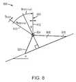
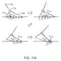
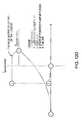
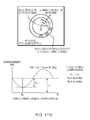
- FIG. 1Ais a schematic illustration of the different phases of a subject's gait cycle over level ground.
- the gait cycleis typically defined as beginning with the heel strike of one foot and ending at the next heel strike of the same foot.
- the gait cycleis broken down into two phases: the stance phase (about 60% of the gait cycle) and the subsequent swing phase (about 40% of the gait cycle).
- the swing phaserepresents the portion of the gait cycle when the foot is off the ground.
- the stance phasebegins at heel-strike when the heel touches the floor and ends at toe-off when the same foot rises from the ground surface.
- the stance phaseis separated into three sub-phases: Controlled Plantarflexion (CP), Controlled Dorsiflexion (CD), and Powered Plantarflexion (PP).
- CPControlled Plantarflexion
- CDControlled Dorsiflexion
- PPPowered Plantarflexion
- CPbegins at heel-strike illustrated at 102 and ends at foot-flat at 106 .
- CPdescribes the process by which the heel and forefoot initially make contact with the ground.
- researchershave shown that that CP ankle joint behavior is consistent with a linear spring response where joint torque is proportional to the displacement of the joint in relation to an equilibrium position of the joint position.
- the spring behavioris, however, variable; joint stiffness is continuously modulated by the body from step to step within the three sub-phases of stance and late swing state.
- the CD phasecontinues until the ankle reaches a state of maximum dorsiflexion and begins powered plantarflexion PP as illustrated at 110 .
- Ankle torque versus position during the CD periodis described as a nonlinear spring where stiffness increases with increasing ankle position. The ankle stores the elastic energy during CD which is necessary to propel the body upwards and forwards during the PP phase.
- the PP phasebegins after CD and ends at the instant of toe-off illustrated at 114 .
- the ankleapplies torque in accordance with a reflex response that catapults the body upward and forward.
- the catapult energyis then released along with the spring energy stored during the CD phase to achieve the high plantarflexion power during late stance.
- This catapult behavioris necessary because the work generated during PP is more than the negative work absorbed during the CP and CD phases for moderate to fast walking speeds.
- the footis lifted off the ground during the swing phase, from toe-off at 114 until the next heel strike at 118 .
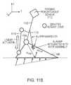
- FIGS. 1B and 1Cshow the human ankle biomechanics during stair ascent.
- the first phase of stair ascentis called Controlled Dorsiflexion 1 (CD 1 ), which begins with foot strike in a dorsiflexed position seen at 130 and continues to dorsiflex until the heel contacts the step surface at 132 .
- CD 1Controlled Dorsiflexion 1
- the anklecan be modeled as a linear spring.
- the second phaseis Powered Plantar flexion 1 (PP 1 ), which begins at the instant of foot flat (when the ankle reaches its maximum dorsiflexion at 132 ) and ends when dorsiflexion begins once again at 134 .
- PP 1Powered Plantar flexion 1
- the human anklebehaves as a torque actuator to provide extra energy to support the body weight.
- the third phaseis Controlled Dorsiflexion 2 (CD 2 ), in which the ankle dorsiflexes until heel-off at 136 .
- the anklecan be modeled as a linear spring.
- the fourth and final phaseis Powered Plantar flexion 2 (PP 2 ) which begins at heel-off 136 and continues as the foot pushes off the step, acting as a torque actuator in parallel with the CD 2 spring to propel the body upwards and forwards, and ends when the toe leaves the surface at 138 to begin the swing phase that ends at 140 .
- PP 2Powered Plantar flexion 2
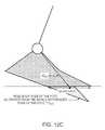
- FIG. 1Cshows the human ankle-foot biomechanics for stair descent.
- the stance phase of stair descentis divided into three sub-phases: Controlled Dorsiflexion 1 (CD 1 ), Controlled Dorsiflexion 2 (CD 2 ), and Powered Plantar flexion (PP).
- CD 1begins at foot strike illustrated at 150 and ends at foot-flat 152 .
- the human anklecan be modeled as a variable damper.
- CD 2the ankle continues to dorsiflex forward until it reaches a maximum dorsiflexion posture seen at 154 .
- the ankleacts as a linear spring, storing energy throughout CD 2 .
- the ankle plantarflexes until the foot lifts from the step at 156 .
- the anklereleases stored CD 2 energy, propelling the body upwards and forwards.
- the footis positioned controlled through the swing phase until the next foot strike at 158 .
- the human ankle-footcan be effectively modeled using a combination of an actuator and a variable stiffness mechanism.
- a variable damperneeds also to be included for modeling the ankle-foot complex; the power absorbed by the human ankle is much greater during stair descent than the power released during stair ascent.
- the inventorshave recognized that during the course of an ordinary day, a person's lower limbs are used to perform and adapt to many different activities in addition to ordinary walking, such as ascending and descending stairs, and walking on inclined ramps.
- the ankle-foot componentsrequire the most power and must exhibit the most terrain-adaptive behavior because these are in the most direct contact with the underlying terrain.
- the inventorshave further recognized that the performance of AFPs can be dramatically improved by dynamically optimizing the mechanical characteristics of the device in different ways and dynamically controlling the device in different ways for each of those activities.
- This applicationdescribes various embodiments of AFPs that perform appropriately in each of these different situations by detecting the terrain that is being traversed, and automatically adapting to the detected terrain.
- the ability to control the AFP for each of these situationsbuilds upon five basic capabilities: (1) determining the activity being performed; (2) dynamically controlling the characteristics of the AFP based on the activity that is being performed; (3) dynamically driving the AFP based on the activity that is being performed; (4) determining terrain texture irregularities (e.g., how sticky is the terrain, how slippery is the terrain, is the terrain coarse or smooth, does the terrain have any obstructions, such as rocks) and responding to these with appropriate fraction control and (5) a mechanical design of the AFP that can respond to the dynamic control and dynamic drive.
- terrain texture irregularitiese.g., how sticky is the terrain, how slippery is the terrain, is the terrain coarse or smooth, does the terrain have any obstructions, such as rocks
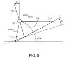
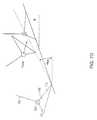
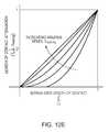
- FIG. 6Ashows the shank trajectories that correspond to five different activities, with additional ramp trajectories to distinguish between steep and shallow ramps.
- the systemcan use this information to figure out what activity is being performed by mapping the tracked trajectory onto a set of activities.
- the trajectory of the lower legBy looking at the trajectory of the lower leg (shank) it is possible to distinguish between flat terrain, ascending or descending stairs, or ascending or descending ramps. For example, when the system recognizes a trajectory it would switch into an appropriate mode, and dynamically control (drive) the AFP as previously established for the mode. Where a trajectory does not fall neatly within a classification, the AFP controller would optimize the response to minimize an objective function in a stochastic control sense or would apply fuzzy logic or adhoc controls based upon the likelihood the terrain falls into a classification.
- IMUinertial measurement unit
- the inventorshave recognized that the performance of the device can be further improved by fine-tuning the characteristics and control of the AFP based on various parameters.
- performancewhen a person is walking slowly (e.g., at a rate of less than 0.9 meters per second), performance can be improved by increasing the impedance of the ankle joint with respect to the impedance used for normal walking Or when a person is walking quickly (e.g., at a rate of 1.7 meters per second), performance can be improved by decreasing the impedance of the ankle joint with to the impedance used for normal walking.
- the controllercan take into account (and modify the output of the controller) that there may be features, texture or irregularities in the terrain (e.g., how sticky is the terrain, how slippery is the terrain, is the terrain coarse or smooth, does the terrain have any obstructions, such as rocks).
- the inventions described hereinrelate generally to lower-extremity prosthetic, orthotic and exoskeleton apparatus.
- Typical use cases for various embodiments of the inventioninclude, for example, metabolic augmentation, permanent assistance for subjects with a permanent limb pathology, or rehabilitation for wearers with temporary limb pathology.
- An example of a use case for an exemplary lower-extremity prosthetic apparatusinvolves the prosthetic replacing the ambulation function of a lower limb of the wearer.
- An example of a use case for an exemplary lower-extremity orthotic apparatusfeatures a method for determining a level of assistance desired for apparatus to apply to a wearer wearing the apparatus. In some embodiments, the level of assistance performed by the orthosis is reduced based on impedance and torque contribution of the wearer to the apparatus.
- the impedance and torque contribution of the weareris determined based on a dynamic, biomechanical model of the wearer and apparatus and measurements of the wearer during operation of the apparatus.
- the measurements of the wearerinclude at least one of rotation and acceleration of at least one joint of the apparatus.
- the axial force and moment applied to the lower leg member of the apparatusis determined based on sensor measurements made using a structural member (pyramid) coupled to the lower leg member of the apparatus.
- the pyramidis an instrumented structure that is a component of a prosthesis and which couples to the limb socket of the wearer.
- the pyramid (structural element) measurementsare used by a controller to determine axial force and moment applied to the lower leg member.
- the apparatusincludes at least one of an ankle joint that connects a foot member of the apparatus to a lower leg member of the apparatus, or a knee joint for connecting a thigh member of the apparatus to the lower leg member of the apparatus, or a hip joint for connecting a torso member of the apparatus to the thigh member of the apparatus.
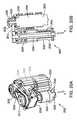
- the inventionin one aspect, features a low noise linear actuator that includes a rotary motor comprising a motor shaft output.
- the actuatoralso includes a screw transmission assembly that includes a threaded shaft coupled to the motor shaft output, the threaded shaft comprising a hollowed out portion containing an acoustic damping material and a nut assembly.
- the screw transmission assemblytranslates rotational motion of the motor shaft output to a linear motion of the nut assembly.
- the screw transmission assemblyis a ball-screw transmission assembly and the nut assembly is a ball-nut assembly, wherein the ball-nut assembly also includes a plurality of ball bearings and a plurality of ball tracks for holding the ball bearings and for recirculating the ball bearings in the ball bearing assembly.
- the actuatorincludes a pulley coupling the motor shaft output to the threaded shaft via a plurality of belts connected in parallel between the pulley and the threaded shaft of the ball-screw transmission assembly.
- the linear actuatorincludes a sensor that validates belt integrity during operation. The pulley can be welded to the motor shaft output.
- the actuatorincludes a radial and thrust bearing coupling the plurality of belts to the threaded shaft to support loads applied by tension in the belts and the threaded shaft.
- the ball-screw transmission assemblyincludes at least one seal for protecting the ball-screw transmission assembly from contaminants.
- the linear actuatoris a component of a lower extremity prosthesis orthosis, or exoskeleton.
- the linear actuatorincludes a transmission that employs traction wheels that couple the motor shaft output to the threaded shaft of the ball-screw transmission assembly.
- the screw transmission assemblycan be a lead screw transmission assembly.
- the inventionin another aspect, features a linear actuator that includes a rotary motor comprising a motor shaft output and a motor drive transmission assembly coupled to the motor shaft output to translate rotational motion of the motor shaft output to a linear motion at an output of the motor drive transmission.
- the linear actuatoralso includes at least one elastic element with bi-directional stiffness connected in series with the motor drive transmission assembly to store energy in tension and compression.
- the linear actuatorincludes a strain sensor coupled to the at least one elastic element for measuring strains in the at least one elastic element.
- the at least one elastic elementcan be a series or parallel elastic element coupled to the output of the motor drive transmission assembly.
- the linear actuatorincludes a controller for receiving measured strain signals for performing closed loop control of the linear actuator thrust force.
- the at least one elastic elementcan be a substantially flat spring divided along a longitudinal axis of the spring minimizing out-of-plane moment applied by the spring to the output of the motor drive transmission assembly.
- the at least one elastic elementcan be a series elastic strain element coupled to the output of the motor drive transmission assembly, and the linear actuator can also include a sensor that measures motor position or position of the output of the motor drive transmission assembly, and at least one sensor that measures the output of the series elastic element, and signal processing electronics that estimates thrust force of the linear actuator for closed loop control of the linear actuator thrust force.
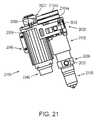
- the inventionin another aspect, features a lower-extremity prosthesis, orthosis or exoskeleton apparatus that includes a foot member, a lower leg member and an ankle joint for connecting the foot member to the lower leg member.
- the apparatusalso includes a first actuator for applying torque to the ankle joint to rotate the foot member with respect to the lower leg member.
- the apparatusalso includes at least one passive elastic members that is a non-compliant stop connected in parallel with the actuator between the lower leg member and the foot member, wherein the non-compliant stop stores little or no energy during dorsiflexion and limits further rotation of the ankle beyond a predefined angle during powered plantar flexion.
- the apparatusincludes an angle adjustment mechanism for setting a pre-specified angle of the foot member relative to the lower leg member at which the non-compliant stop limits further rotation.
- the angle adjustment mechanismcan include a screw adjustable component for setting the pre-specified angle.
- the angle adjustment mechanismcan include an actuator for setting the pre-specified angle.
- the actuatoradjusts the pre-specified angle based on a property of the underlying terrain.
- the property of the underlying terrainis selected from the group consisting of ascending ramp, descending ramp, ascending stair, descending stair, level surface.
- a controller associated with the apparatusdetermines the property of the underlying terrain on an intra-cycle basis.
- the prosthesisincludes an inertial measurement unit for determining an inertial pose of the lower leg member.
- the inertial measurement unitcan be coupled to the lower leg member.
- the inertial measurement unitcan be coupled to the foot member.
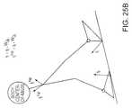
- the prosthesisincludes a controller for calculating ground reaction force and zero moment pivot coordinates imparted by an underlying surface onto the foot member based on an inertial pose of the lower leg member, the torque applied to the lower leg member by the actuator, axial force applied to the lower leg member, and an angle between the foot member and lower leg member.
- the controlleris coupled to the actuator and is configured to control the actuator for modulating at least one of an impedance, position or torque of the prosthesis throughout a walking cycle of the prosthesis based on the inertial pose trajectory of the lower leg member, the angle between the foot member and lower leg member, and the ground reaction force and the zero moment pivot coordinates.
- the controlleris coupled to the actuator and is configured to control the actuator for modulating an impedance of the prosthesis as the wearer stands up from a seated position or sits down from a standing position based on the inertial pose of the lower leg member, the angle between the foot member and lower leg member, and the ground reaction force and the zero moment pivot coordinates.
- the inventionin another aspect, features a lower-extremity prosthesis that includes a foot member, a lower leg member and an ankle joint for connecting the foot member to the lower leg member.
- the prosthesisincludes a first actuator for applying torque to the ankle joint to rotate the foot member with respect to the lower leg member.
- the prosthesisalso includes a structural element coupled to the lower leg member and includes an interface for coupling to a limb socket member of a wearer.
- the prosthesisalso includes a displacement sensing apparatus for measuring deflection of the structural element for determining the torque applied to the lower leg member by the actuator and the axial force applied to the lower leg member.
- the displacement sensing apparatusincludes a plurality of sensors and the displacement sensing apparatus measures the distance between each sensor and a surface of the structural element.
- the sensorscan be selected from the group consisting of contact displacement sensors, non-contact displacement sensors, inductive coils, optical sensors, force-sensitive resistors, piezoelectric sensors, or strain sensors.
- the plurality of sensorsinclude a plurality of inductive coils on a circuit board. In some embodiments, changes in inductance of the inductive coils relative to a surface of the structural element are used to determine the displacement of the structural element.
- the prosthesisincludes an inertial measurement unit for determining an inertial pose of the lower leg member.
- the inertial measurement unitis coupled to the lower leg member. In some embodiments, the inertial measurement unit is coupled to the foot member.
- the prosthesisincludes a controller for calculating ground reaction force and zero moment pivot coordinates imparted by an underlying surface onto the foot member based on an inertial pose trajectory of the lower leg member, the torque applied to the lower leg member by the actuator, axial force applied to the lower leg member, and an angle between the foot member and lower leg member.
- the controlleris coupled to the actuator and is configured to control the actuator for modulating an impedance of the prosthesis throughout a walking cycle of the prosthesis based on the inertial pose trajectory of the lower leg member, the angle between the foot member and lower leg member, and the ground reaction force and the zero moment pivot coordinates.
- the controlleris coupled to the actuator and is configured to control the actuator for modulating an impedance of the prosthesis as the wearer stands up from a seated position or sits down from a standing position based on the inertial pose trajectory of the lower leg member, the angle between the foot member and lower leg member, and the ground reaction force.
- the inventionin another aspect, features an active knee orthosis that includes a thigh member attachable to a thigh of a wearer, a lower leg member attachable to a lower leg of the wearer and a knee joint for connecting the thigh member to the lower leg member.
- the orthosisalso includes a rotary motor comprising a motor shaft output.
- the orthosisalso includes a motor drive transmission assembly coupled to the motor shaft output to translate rotational motion of the motor shaft output to a linear motion at an output of the motor drive transmission assembly.
- the orthosisalso includes a drive transmission assembly coupled to the output of the motor drive transmission, an output of the drive transmission assembly is coupled to the lower leg member for applying torque to the knee joint to rotate the lower leg member with respect to the thigh member.
- the orthosisalso includes a motor angle sensor for determining motor position.
- the orthosisalso includes a controller for controlling the rotary motor for modulating impedance, position or torque of the of the orthosis throughout a walking cycle of the orthosis based on the motor position.
- the orthosisincludes an angle sensor for determining position of a drum of the drive transmission assembly relative to the output of the motor drive transmission assembly and wherein the controller controls the rotary motor for modulating impedance, position or torque based on the position.
- the orthosisincludes a displacement sensor for measuring displacement of a series spring in the motor drive transmission assembly for determining force on the series spring and wherein the controller controls the rotary motor for modulating impedance, position or torque based on the force on the spring.
- the orthosisincludes an inertial measurement unit coupled to the thigh member or lower leg member for determining an inertial pose trajectory of the lower leg member and wherein the controller controls the rotary motor for modulating impedance, position or torque based on the inertial pose.
- the orthosisincludes a sensor for determining the force applied to at least one of the lower leg member and thigh member by the drive transmission assembly and wherein the controller controls the rotary motor for modulating impedance, position or torque based on the torque applied to the lower leg member.
- the orthosisincludes an angle sensor for determining an angle between the thigh member and lower leg member and wherein the controller controls the rotary motor for modulating impedance, position or torque based on the angle between the thigh member and lower leg member.
- the orthosisincludes the drive transmission is selected from the group consisting of a belt drive transmission, band drive transmission and cable drive transmission.
- the orthosisincludes a cuff coupled to the thigh member for attaching the orthosis to the thigh of the wearer.
- the orthosisincludes a cuff coupled to the lower leg member for attaching the orthosis to the lower leg of the wearer.
- the orthosisaugments lower extremity functions of the wearer. In some embodiments, the orthosis treats a lower extremity pathology of the wearer. In some embodiments, the controller is configured to vary assistance provided by the orthosis to the wearer during rehabilitation of a lower extremity pathology of the wearer.
- the inventionin another aspect, features an active knee orthosis that includes a thigh member attachable to a thigh of a wearer, a lower leg member attachable to a lower leg of the wearer, and a knee joint for connecting the thigh member to the lower leg member.
- the orthosisalso includes a rotary motor comprising a motor shaft output.
- the orthosisalso includes a screw transmission assembly coupled to the motor shaft output for converting the rotary motion of the motor shaft output to a linear motion output by the screw transmission assembly.
- the orthosisalso includes a belt, band or cable drive transmission assembly coupled to the output of the screw transmission assembly to convert a linear motion output by the screw transmission assembly to a rotary motion for applying torque to the knee joint to rotate the lower leg member with respect to the thigh member.
- the orthosisalso includes a motor angle sensor for determining motor position.
- the orthosisalso includes a controller for controlling the rotary motor for modulating impedance, position or torque of the of the orthosis throughout a walking cycle of the orthosis based on the motor position.
- the orthosisincludes a displacement sensor for measuring displacement of a series spring in the belt, band or cable drive transmission for determining force on the series spring and wherein the controller controls the rotary motor for modulating impedance, position or torque based on the force on the spring.
- the orthosisincludes an inertial measurement unit coupled to the thigh member or lower leg member for determining, within a gait cycle, an inertial pose trajectory of the lower leg member and wherein the controller controls the rotary motor for modulating impedance, position or torque based on the inertial pose trajectory during the gait cycle.
- the orthosisincludes a torque sensor for determining torque applied to the lower leg member by the belt, band or cable drive transmission and wherein the controller controls the rotary motor for modulating impedance, position or torque within the gait cycle based on the force applied to the lower leg member.
- the orthosisincludes an angle sensor for determining an angle between the thigh member and lower leg member and wherein the controller controls the rotary motor for modulating impedance, position or torque based on the angle between the thigh member and lower leg member within the gait cycle.
- the belt, band or cable drive transmissioncomprises at least two drive transmissions, wherein a first of the at least two drive transmissions is configured to convert a first direction of a linear motion output by the screw transmission assembly to a first rotary motion for applying torque to the knee joint to rotate the lower leg member with respect to the thigh member and wherein a second of the at least two transmissions is configured to convert an opposite direction of a linear motion output by the screw transmission assembly to an opposite rotary motion for applying torque to the knee joint to rotate the lower leg member with respect to the thigh member.
- the inventionin another aspect, features a method for determining ground reaction forces and zero moment pivot imparted by an underlying surface onto a foot member of a lower extremity prosthetic apparatus worn by a wearer.
- the apparatusincludes a foot member, a lower leg member, and an ankle joint for connecting the foot member to the lower leg member and a first actuator for applying torque to the ankle joint to rotate the foot member with respect to the lower leg member.
- the methodinvolves calculating the ground reaction force based on an inertial pose of the lower leg member, the torque applied to the lower leg member by the actuator, axial force applied to the lower leg member, and an angle between the foot member and lower leg member.
- the methodincludes controlling the actuator for modulating an impedance of the apparatus throughout a walking cycle of the apparatus based on the inertial pose of the lower leg member, the angle between the foot member and lower leg member, the ground reaction force and the zero moment pivot. In some embodiments, the method includes controlling the actuator for modulating an impedance of the apparatus as the wearer stands up from a seated position or sits down from a standing position based on the inertial pose of the lower leg member, the angle between the foot member and lower leg member, the ground reaction force and the zero moment pivot. In some embodiments, the inertial pose of the lower leg member is determined based on an output of an inertial measurement unit coupled to the lower leg member.
- the inventionin another aspect, features a method for minimizing the effect of accelerometer and rate gyro errors on a lower extremity prosthesis or orthosis that includes a foot member, a lower leg member, and an ankle joint for connecting the foot member to the lower leg member.
- the methodincludes determining at least one velocity error contribution for an accelerometer signal output by an accelerometer coupled to the lower leg member when the ankle joint is substantially stationary during a walking cycle of the prosthesis or orthosis.
- the methodalso includes determining at least one velocity error contribution for an inertial pose misalignment signal output by an inertial measurement unit coupled to the lower leg member when the ankle joint is substantially stationary during a walking cycle of the prosthesis or orthosis.
- the inertial pose misalignment signal output by the inertial measurement unitis a rate gyro signal output by a rate gyro.
- the methodincludes computing the pose of the lower leg member using signals output by the accelerometer and rate gyro.
- the methodincludes correcting the computed pose of the lower leg member using the velocity error contributions.
- the methodincludes the velocity error contributions are determined during a portion of a controlled dorsiflexion state of the walking cycle.
- the methodincludes determining velocity error contributions for an accelerometer signal and rate gyro signal output by an accelerometer and rate gyro coupled to a thigh member of the prosthesis or orthosis when the ankle joint is substantially stationary during a walking cycle of the prosthesis or orthosis. In some embodiments, the method includes determining velocity error contributions for an accelerometer signal and rate gyro signal output by an accelerometer and rate gyro coupled to a thigh member of the prosthesis or orthosis when a computed position on a foot member is substantially stationary.
- the methodincludes measuring the angle of the lower leg member relative to the thigh member. In some embodiments, the method includes determining velocity error contributions for an accelerometer signal and rate gyro signal output by an accelerometer and rate gyro coupled to a wearer's torso when the ankle joint is substantially stationary during a walking cycle of the prosthesis or orthosis. In some embodiments, the method includes measuring the angle of the thigh member relative to the wearer's torso.
- the inventionin another aspect, features a method for controlling balance of a wearer wearing a lower extremity prosthetic, orthotic or exoskeleton apparatus that includes a foot member, a lower leg member, and an ankle joint for connecting the foot member to the lower leg member.
- the methodincludes adjusting at least one of the ankle joint impedance, position or torque of the apparatus based on inertial pose of the lower leg member, angle between the lower leg member and the foot member and ground reaction force and the zero moment pivot imparted by an underlying surface onto the foot member.
- the actuatorcoupled to the lower leg member and foot member, adjusts the at least one of the ankle joint impedance, position or torque to control the balance of the wearer.
- a controllercalculates the ground reaction force and the zero moment pivot based on an inertial pose of the lower leg member, the torque applied to the lower leg member by the actuator, axial force applied to the lower leg member, and an angle between the foot member and lower leg member, the controller is coupled to the actuator to control the actuator to adjust the at least one of the ankle joint impedance, position or torque to control the balance of the wearer.
- the controllercalculates the inertial pose of the lower leg based on a signal output from an inertial measurement unit coupled to the lower leg.
- a controller coupled to the actuatorcontrols the actuator to adjust the at least one of the ankle joint impedance, position or torque to control the balance of the wearer.
- the controllerreceives signals from one or more sensors to calculate the inertial pose of the lower leg member, angle between the lower leg member and the foot member and the ground reaction force imparted by the underlying surface onto the foot member.
- the methodincludes controlling balance of the wearer as the wearer transitions from a sitting position to a standing position based on an increase in the ground reaction force. In some embodiments, the method includes driving the lower leg member forward with an actuator coupled to the lower leg based on the increase in the ground reaction force.
- the inventionin another aspect, features a method for determining a change in traction between a foot member of an orthotic, prosthetic or exoskeleton apparatus and an underlying surface
- the apparatusincludes g a foot member, a lower leg member, an ankle joint for connecting the foot member to the lower leg member and a first actuator for applying torque to the ankle joint to rotate the foot member with respect to the lower leg member.
- the methodincludes calculating ground reaction force and the zero moment pivot imparted by an underlying surface onto the foot member based on an inertial pose of the lower leg member, the torque applied to the lower leg member by the actuator, axial force applied to the lower leg member, and an angle between the foot member and lower leg member.
- the methodalso includes calculating velocity of the foot member zero moment pivot based on the inertial pose of the lower leg member, the torque applied to the lower leg member by the actuator, the axial force applied to the lower leg member, and the angle between the foot member and lower leg member.
- the methodincludes reducing torque applied to the lower leg member in response to determining that the foot member is slipping or sinking. In some embodiments, the method includes reducing the torque applied to the lower leg member by an attenuation factor.
- the attenuation factorcan be a predetermined attenuation factor. The attenuation factor can be determined based on the zero moment pivot velocity. In some embodiments, the method includes reducing the torque applied to the lower leg member in response to the zero moment pivot velocity being below a predetermined threshold.
- the inventionin another aspect, features a linear actuator having intrinsic safety features.
- the actuatorincludes a rotary motor that includes a motor shaft output, wherein a pulley is coupled to the motor shaft output.
- the actuatoralso includes a ball-screw transmission assembly that includes a threaded shaft coupled to the motor shaft output by a plurality of belts connected in parallel between the pulley and the threaded shaft of the ball-screw transmission assembly.
- the ball-screw transmission assemblytranslates rotational motion of the motor shaft output to a linear motion of a portion of the ball-screw transmission assembly.
- the linear actuatorincludes an angular encoder for determining angular alignment between the rotary motor's rotor and stator.
- the linear actuatorincludes a controller configured to short three leads of the rotary motor to ground in response to a belt breakage sensor detecting a failure of one or more of the plurality of belts. In some embodiments, shorting the three leads results in the rotary motor functioning as a stiff, viscous brake.
- the temperature of the motoris determined by applying a fixed current to a winding of the motor winding and measuring a corresponding voltage in the winding to determine the winding resistance.
- the temperature of the motoris determined by applying a fixed voltage to a winding of the motor winding and measuring a corresponding current in the winding to determine the winding resistance.
- the linear actuatorincludes a motor temperature sensor for measuring the temperature of the motor.
- the linear actuatorincludes a controller coupled to the motor for controlling torque output by the actuator based on temperature of the motor.
- the inventionin another aspect, features a method for controlling throughout a gait cycle at least one of joint position, impedance or torque of a lower-extremity prosthetic, orthotic, or exoskeleton apparatus worn by a wearer based on an inertially-referenced, intra-cycle trajectory of a portion of the apparatus over underlying terrain.
- the apparatusincludes a foot member, a lower leg member, and an ankle joint for connecting the foot member to the lower leg member.
- the apparatusincludes a lower leg member, a thigh member, and a knee joint for connecting the lower leg member to the thigh member.
- the apparatusincludes a thigh member, a torso member, and a hip joint for connecting the thigh member to the torso member.
- the apparatusincludes a thigh member and a knee joint for connecting the lower leg member to the thigh member.
- the apparatusincludes a torso member, and a hip joint for connecting the thigh member to the torso member.
- the apparatusincludes a torso member, and a hip joint for connecting the thigh member to the torso member.
- the apparatusincludes a torso member, and a hip joint for connecting the thigh member to the torso member.
- the trajectoryis determined for the lower leg member. In some embodiments, the trajectory is determined based on an inertial pose of the lower leg member and an angle between the foot member and lower leg member. In some embodiments, the spring equilibrium position of the foot member is adjusted to a foot-flat position relative to the underlying terrain to coincide with the lower leg member being in a vertical position relative to a world coordinate system. In some embodiments, the impedance of the apparatus is adjusted to minimize a cost function based on projected force imparted on the lower leg member during a period of time between when a foot member strikes the underlying terrain and when the foot member is positioned in a flat-foot position relative to the underlying terrain.
- the impedance of the apparatusis adjusted to minimize a cost function based on projected force imparted on the lower leg member during a period of time between when a foot member strikes the underlying terrain to when the foot member is positioned in a flat-foot position relative to the underlying terrain.
- the impedance of the apparatusis adjusted to minimize foot slap of the foot member.
- the position of the foot memberis adjusted to a toe down position relative to the underlying terrain based on the trajectory of the lower leg member.
- the trajectory of the lower leg memberis representative of trajectory when the underlying surface comprises one or more stairs.
- the at least one of joint position, impedance or torqueis updated continuously during the gait cycle by a processor in communication with at least one sensor and one actuator of the apparatus.
- the impedance and torque on the joint of the apparatusis controlled during a late stance phase of the gait cycle based on at least one of ambulation speed, terrain context or terrain texture. In some embodiments, the impedance and torque are controlled to achieve a desired amount of work.
- the impedance of the apparatusis adjusted during a controlled plantar flexion phase of the gait cycle to minimize forefoot collisions with the underlying terrain.
- the at least one of joint position, impedance or torque of the apparatusis controlled based on speed of a portion the apparatus.
- the apparatusis a lower-leg apparatus and the portion is a location between a knee joint and ankle joint of the lower-leg apparatus.
- at least two of the joint position, the impedance or the torqueare controlled.
- the apparatusincludes, throughout the gait cycle, the joint position, the impedance and the torque are controlled.
- the inventionin another aspect, features a method for reducing, throughout a gait cycle, hip impact force and hip impact force rate of a lower-extremity prosthetic, orthotic, or exoskeleton apparatus worn by a wearer.
- the methodincludes generating a cost function based on hip impact force and force rate generated by transmission of foot contact with underlying terrain.
- the methodalso includes controlling at least one of position, impedance or torque of at least one joint of the lower-extremity prosthetic, orthotic, or exoskeleton apparatus based on minimizing the cost function wearer to reducing hip impact forces generated during a gait cycle over the underlying terrain.
- the apparatusincludes a first foot member, first lower leg member and a first ankle joint for connecting the first foot member to the first lower leg member, and the method also includes adjusting impedance of the first ankle joint and an angle between the first foot member and first lower leg member during a time interval between a foot-strike condition and foot-flat condition of the first foot member of the apparatus.
- the impedance of the first ankle joint and the angle between the first foot member and the first lower leg memberis adjusted to minimize a cost function based on an estimation of force to be imparted on the first ankle joint between the foot-strike condition and the foot-flat condition of the first foot member of the apparatus.
- the foot-strike conditionincludes the foot member heel first striking the underlying terrain.
- the foot-strike conditioncomprises the foot member toe first striking the underlying terrain.
- the underlying terrainincludes at least one ascending or descending stair
- the methodalso includes constraining the first foot member to achieve a toe first striking of the underlying terrain while minimizing the cost function based on the estimation of force to be imparted on the first ankle joint between the foot-strike condition and the foot-flat condition of the first foot member of the apparatus.
- the apparatusincludes a second leg member, a second foot member and a second ankle joint for connecting the second leg member to the second foot member, and the method also includes applying a torque to the second ankle joint at or before time of impact of the first foot member with the underlying terrain.
- the methodincludes controlling at least two of the joint position, the impedance or the torque. In some embodiments, the method includes controlling the joint position, the impedance and the torque.
- the inventionin another aspect, features a method for minimizing, throughout a gait cycle, work performed by a lower-extremity prosthetic, orthotic, or exoskeleton apparatus worn by a wearer.
- the methodincludes generating a cost function for estimating intra-step transition work performed by a combination of the apparatus and subject on center of mass of the combination during double support.
- the methodalso includes controlling at least one of position, impedance or torque of at least one joint of the lower-extremity prosthetic, orthotic, or exoskeleton apparatus based on minimizing the cost function wearer to reducing the work performed by the wearer and apparatus generated during a gait cycle.
- the apparatusincludes a first foot member, first lower leg member and a first ankle joint for connecting the first foot member to the first lower leg member
- the methodalso includes adjusting impedance of the first ankle joint and an angle between the first foot member and first lower leg member during a time interval between a foot-strike condition and foot-flat condition of the first foot member of the apparatus.
- the impedance of the first ankle joint and the angle between the first foot member and the first lower leg memberis adjusted to minimize a cost function based on an estimation of force to be imparted on the first ankle joint between the foot-strike condition and the foot-flat condition of the first foot member of the apparatus.
- the foot-strike conditioncan include the foot member heel first striking underlying terrain.
- the foot-strike conditioncan include the foot member toe first striking underlying terrain.
- the terrain underlying the wearerincludes at least one ascending or descending stair
- the methodalso includes constraining the first foot member to achieve a toe first striking of the underlying terrain while minimize the cost function based on the estimation of force to be imparted on the first ankle joint between the foot-strike condition and the foot-flat condition of the first foot member of the apparatus.
- the apparatusincludes a second leg member, a second foot member and a second ankle joint for connecting the second leg member to the second foot member, and the method also includes applying a torque to the second ankle joint at or before time of impact of the first foot member with underlying terrain.
- the methodincludes controlling throughout the gait cycle at least two of the joint position, the impedance or the torque. In some embodiments, the method includes controlling throughout the gait cycle the joint position, the impedance and the torque.
- the inventionin another aspect, features a method for controlling at least one of joint impedance, position or torque of a lower-extremity prosthetic, orthotic or exoskeleton apparatus worn by a wearer during intra-cycle ambulation.
- the methodalso includes determining trajectory of a location between an ankle joint and knee joint of the apparatus in a coordinate system throughout a walking cycle.
- the methodalso includes adjusting the articulation of a foot member of the apparatus based on the trajectory.
- the ankle jointconnects the foot member to a first end of the lower leg member of the apparatus and the knee joint is connected to an opposite end of the lower leg member.
- the apparatusincludes the location is the ankle joint.
- the methodincludes adjusting the articulation of the foot member to a heel down position when the predetermined condition is representative of the presence of level ground, an ascending ramp, or a descending ramp in underlying terrain. In some embodiments, the method includes adjusting the articulation of the foot member to a toe down position when the predetermined condition is indicative of the presence of an ascending stair or a descending stair in underlying terrain. In some embodiments, the foot member is adjusted to a dorsiflexed position relative to a lower leg member of the apparatus when the predetermined condition is representative of the presence of an ascending stair. In some embodiments, the foot member is adjusted to a plantar flexed position relative to a lower leg member of the apparatus when the predetermined condition is representative of the presence of a descending stair.
- the methodincludes adjusting the articulation of the foot member to a heel down position when the predetermined condition is representative of the presence of level ground, an ascending ramp, or a descending ramp in underlying terrain, and adjusting the articulation of the foot member to a toe down position when the predetermined condition is representative of the presence of an ascending stair or a descending stair in underlying terrain.
- the trajectoryis determined based on an inertial pose of a lower leg member of the apparatus and an angle between the foot member and lower leg member.
- the methodincludes adjusting the articulation of the foot member of the apparatus to a predetermined orientation when the trajectory satisfies a predetermined condition.
- the inventionin another aspect, features an active lower extremity prosthetic, orthotic or exoskeleton apparatus.
- the apparatusincludes a foot member, a lower leg member, and an ankle joint for connecting the foot member to the lower leg member.
- the apparatusalso includes a first actuator for applying torque to the ankle joint to rotate the foot member with respect to the lower leg member and an inertial measurement unit for determining an inertial pose of the lower leg member.
- the apparatusalso includes a torque sensor for determining torque applied to the lower leg member by the actuator.
- the apparatusalso includes a force sensor for determining axial force applied to the lower leg member.
- the apparatusalso includes an angle sensor for determining an angle between the foot member and lower leg member.
- the apparatusalso includes a controller for controlling the actuator for modulating at least one of joint impedance, position or torque of the apparatus throughout a walking cycle of the apparatus based on the inertial pose, torque, axial force and angle.
- the apparatusincludes one or more passive elastic members connected between the lower leg member and the foot member for storing energy when the foot member rotates about the ankle joint toward the lower leg member and for releasing energy to apply additional torque to rotate the foot member away from the lower leg member.
- the one or more passive elastic membersis attached to the apparatus in parallel with the actuator.
- the one or more passive elastic membersis a unidirectional spring and is not engaged during plantar flexion of the foot member relative to the lower leg member.
- the actuatorincludes a series elastic actuator.
- the series elastic actuatorcomprises a brushless motor that drives a ball-screw, a carbon-fiber spring in series with an output of the ball-screw, and a strain sensor coupled to the spring.
- the inertial measurement unitcomprises a three-axis rate gyro and a three-axis accelerometer.
- the apparatusincludes a structural element coupled to the lower leg member and which also includes an interface for coupling to a limb socket member of a wearer, wherein the structural element comprises a plurality of strain gages for determining the torque applied to the lower leg member by the actuator and the axial force applied to the lower leg member.
- the actuatoradjusts stiffness of the apparatus during controlled plantar flexion phase of the walking cycle to minimize forefoot collisions with an underlying surface.
- the actuatorcontrols impedance and torque on the ankle joint of the apparatus during a late stance phase of the walking cycle based on at least one of ambulation speed, terrain context or terrain texture.
- the actuatormodulates impedance of the apparatus based on a ground reaction force and zero moment pivot coordinates imparted by an underlying surface onto the foot member, the inertial pose of the lower leg member, the torque applied to the lower leg member by the actuator, the axial force applied to the lower leg member, and the angle between the foot member and lower leg member.
- the actuatormodulates the impedance of the apparatus as the wearer stands up from a seated position or sits down from a standing position based on the inertial pose of the lower leg member, the angle between the foot member and lower leg member, and the ground reaction force and zero moment pivot coordinates.
- the apparatusis used to treat drop foot gait. In some embodiments, the apparatus is used to treat a wearer having anterior muscle weakness, posterior muscle weakness, or a combination thereof.
- the apparatusincludes a thigh member, a knee joint for connecting the thigh member to the lower leg member and a second actuator for applying torque to the knee joint to rotate the lower leg member with respect to the thigh member.
- the apparatusalso includes a second inertial measurement unit for determining an inertial pose of the thigh member and a second torque sensor for determining torque applied to the thigh member by the second actuator.
- the apparatusalso includes a second force sensor for determining axial force applied to the thigh member.
- the apparatusalso includes a second angle sensor for determining an angle between the thigh member and lower leg member.
- the apparatusalso includes a controller that controls the first and second actuator for modulating an impedance of the apparatus throughout a walking cycle of the apparatus based on the inertial pose, torque, axial force and angle determined using the first and second devices.
- the apparatusincludes a torso member and a hip joint for connecting the torso member to the thigh member.
- the apparatusalso includes a third actuator for applying torque to the hip joint to rotate the thigh member with respect to the torso member.
- the apparatusalso includes a third inertial measurement unit for determining an inertial pose of the torso member and a third torque sensor for determining torque applied to the torso member by the third actuator.
- the apparatusalso includes a third force sensor for determining axial force applied to the torso member and a third angle sensor for determining an angle between the torso member and the thigh member, wherein the controller controls the first, second and third actuator for modulating an impedance of the apparatus throughout a walking cycle of the apparatus based on the inertial pose, torque, axial force and angle determined using the first, second, and third devices.
- the lower leg memberis attachable to a leg of the wearer.
- the foot memberis attachable to a foot of the wearer.
- the thigh memberis attachable to a thigh of the wearer.
- the controllercontrols the actuator to modulate at least two of joint impedance, position or torque of the apparatus throughout a walking cycle of the apparatus. In some embodiments, the controller controls the actuator to modulate joint impedance, position and torque of the apparatus throughout a walking cycle of the apparatus.
- the inventionin another aspect, features a method for determining a level of assistance desired for a lower-extremity orthotic or exoskeleton apparatus to apply to a wearer wearing the apparatus.
- the methodincludes specifying a physical therapy protocol defining a level of assistance performed by the apparatus on the wearer over a period of time and reducing the level of assistance performed by the apparatus on the wearer to assist in rehabilitation of the limb pathology.
- the level of assistance by the apparatusis reduced based on impedance and torque contribution of the wearer to the apparatus.
- the apparatusincludes the impedance and torque contribution of the wearer is determined based on a biomechanical model of the wearer and apparatus and measurements of the wearer during operation of the apparatus.
- the measurements of the wearerinclude at least one of rotation and acceleration of at least one joint of the apparatus.
- the at least one joint of the apparatusincludes at least one of a) an ankle joint that connects a foot member of the apparatus to a lower leg member of the apparatus; b) a knee joint for connecting a thigh member of the apparatus to the lower leg member of the apparatus; or c) a hip joint for connecting a torso member of the apparatus to the thigh member of the apparatus.
- the inventionin another aspect, features a method for rehabilitation of a wearer with a limb pathology using a lower-extremity orthotic or exoskeleton apparatus worn by a wearer.
- the methodincludes estimating impedance and torque contribution of the wearer to at least one joint of the apparatus based on a biomechanical model of the wearer and apparatus and measurements of the wearer during operation of the apparatus and providing a signal to an actuator of the apparatus that commands the actuator to provide additional torque to at least one joint of the apparatus such that a predetermined level of torque is achieved in the apparatus during operation.
- the measurements of the wearerinclude at least one of rotation and acceleration of at least one joint of the apparatus.
- the at least one joint of the apparatusincludes at least one of a) an ankle joint that connects a foot member of the apparatus to a lower leg member of the apparatus; b) a knee joint for connecting a thigh member of the apparatus to the lower leg member of the apparatus; or c) a hip joint for connecting a torso member of the apparatus to the thigh member of the apparatus.
- the inventionin another aspect, features a method for estimating a condition of underlying terrain while a wearer is traversing the underlying terrain.
- the methodincludes determining an inertially-referenced trajectory of points on a lower limb of a wearer and orientation of the lower limb of the wearer traversing underlying terrain and analyzing the inertially-referenced trajectory relative to at least one predetermined trajectory model to estimate an underlying terrain condition.
- the underlying terrain conditionis at least one of stair ascent, ramp ascent, level ground, ramp descent, or stair descent.
- the methodincludes determining the inertially-referenced trajectory of the wearer traversing underlying terrain, wherein the underlying terrain includes stair ascent, ramp ascent, level ground, ramp descent, and stair descent. In some embodiments, the determining an inertially-referenced trajectory of a wearer traversing underlying terrain is performed during late swing phase of a gait cycle of the wearer.
- analyzing the inertially-referenced trajectory relative to at least one predetermined trajectory modelincludes using at least one pattern recognition technique.
- the at least one pattern recognition techniqueis performed using a processor coupled to at least one sensor and one actuator coupled to a lower-extremity prosthetic, orthotic, or exoskeleton apparatus worn by a wearer.
- the at least one pattern recognition techniqueis selected from the group techniques consisting of Bayesian pattern classification, neural nets, fuzzy logic or hierarchical temporal memory.
- the methodincludes controlling at least one of joint impedance, position or torque of a lower-extremity prosthetic, orthotic, or exoskeleton apparatus worn by a wearer based on the underlying terrain condition estimate.
- the methodincludes determining a change in traction between a foot member of the apparatus and the underlying surface in which the apparatus includes a foot member, a lower leg member, an ankle joint for connecting the foot member to the lower leg member and a first actuator for applying torque to the ankle joint to rotate the foot member with respect to the lower leg member.
- the methodcan include calculating ground reaction force imparted by the underlying surface onto the foot member based on an inertial pose of the lower leg member, the torque applied to the lower leg member by the actuator, axial force applied to the lower leg member, and an angle between the foot member and lower leg member; and calculating velocity of the foot member zero moment pivot based on the inertial pose of the lower leg member, the torque applied to the lower leg member by the actuator, the axial force applied to the lower leg member, and the angle between the foot member and lower leg member.
- the methodincludes reducing torque applied to the lower leg member in response to determining that the foot member is slipping or sinking. In some embodiments, the method includes reducing the torque applied to the lower leg member by an attenuation factor. In some embodiments, the attenuation factor is a predetermined attenuation factor. In some embodiments, the attenuation factor is determined based on the zero moment pivot velocity. In some embodiments, the method includes reducing the torque applied to the lower leg member in response to the zero moment pivot velocity being below a predetermined threshold.
- the inventionin another aspect, features a method for discriminating between properties of terrain underlying a lower extremity prosthetic, orthotic, or exoskeleton apparatus worn by a wearer, in which the apparatus includes a foot member, a lower leg member, and an ankle joint for connecting the foot member to the lower leg member.
- the methodincludes estimating an inertial velocity vector attack angle of the ankle joint of the apparatus throughout a gait cycle and discriminating between terrain properties based on whether the inertial velocity vector attack angle lies within a predetermined range.
- the methodincludes adjusting the impedance of the apparatus to minimize a cost function based on projected force imparted on the lower leg member during a period of time between when a heel of the foot member strikes the underlying terrain to when the foot member is positioned in a flat-foot position relative to the underlying terrain.
- the methodincludes controlling at least one of ankle joint impedance, position or torque of the apparatus based on whether the inertial velocity vector attack angle lies within a predetermined range.
- the foot memberis attachable to a foot of the wearer and the lower leg member is attachable to a leg of the wearer.
- the foot member and lower leg memberreplace the foot and lower leg of the wearer.
- the inventionin another aspect, features a method for controlling at least one of joint impedance, position or torque of a lower extremity prosthetic, orthotic, or exoskeleton apparatus worn by a wearer, wherein the apparatus includes a foot member, a lower leg member, and an ankle joint for connecting the foot member to the lower leg member.
- the methodincludes estimating an inertial velocity vector attack angle of the ankle joint of the apparatus throughout a gait cycle and adjusting the position of a foot member of the apparatus to a toe down position when the velocity vector attack angle lies within a predefined range.
- the methodincludes adjusting the position of the foot member to a heel down position when the inertial velocity vector attack angle is outside of the predetermined range. In some embodiments, the method includes adjusting the impedance of the apparatus to minimize a cost function based on projected force imparted on the lower leg member during a period of time between when a heel of the foot member strikes the underlying terrain to when the foot member is positioned in a flat-foot position relative to the underlying terrain. In some embodiments, the foot member is attachable to a foot of the wearer and the lower leg member is attachable to a leg of the wearer. In some embodiments, the foot member and lower leg member replace the foot and lower leg of the wearer.
- the inventionin another aspect, features a method of operating a lower-extremity prosthesis or orthosis apparatus, in which the apparatus includes a foot member and an ankle joint.
- the methodincludes tracking a trajectory of a portion of the apparatus and determining whether the tracked trajectory corresponds to stairs.
- the methodalso includes optimizing operation of the apparatus for locomotion on stairs, in situations where the tracked trajectory corresponds to stairs.
- the methodalso includes determining whether the tracked trajectory corresponds to non-stair terrain.
- the methodalso includes optimizing operation of the apparatus for locomotion on non-stair terrain, in situations where the tracked trajectory corresponds to non-stair terrain.
- determining whether the tracked trajectory corresponds to stairscomprises determining that a velocity vector attack angle ⁇ of the ankle joint in a late swing phase is below a threshold value, and the step of determining whether the tracked trajectory corresponds to non-stair terrain comprises determining that a velocity vector attack angle ⁇ of the ankle joint is above the threshold value.
- optimizing operation of the apparatus for walking on stairscomprises adjusting a position of the foot member to a toe down position prior to foot strike, and wherein the step of optimizing operation of the apparatus for locomotion on non-stair terrain comprises adjusting a position of the foot member to a heel down position prior to foot strike.
- optimizing operation of the apparatus for walking on non-stair terrainincludes dynamically controlling an impedance of the ankle joint during different phases of a single step, dynamically controlling a position of the ankle joint during different phases of a single step, and dynamically controlling torque of the ankle joint during different phases of a single step.
- optimizing operation of the apparatus for walking on stairsincludes dynamically controlling an impedance of the ankle joint during different phases of a single step, dynamically controlling a position of the ankle joint during different phases of a single step, and dynamically controlling torque of the ankle joint during different phases of a single step.
- the methodincludes determining whether the tracked trajectory corresponds to an ascending ramp; optimizing operation of the apparatus for ascending a ramp in situations where the tracked trajectory corresponds to an ascending ramp; determining whether the tracked trajectory corresponds to a descending ramp; and optimizing operation of the apparatus for descending a ramp in situations where the tracked trajectory corresponds to a descending ramp.
- optimizing operation of the apparatus for ascending a rampincludes dynamically controlling an impedance of the ankle joint during different phases of a single step, dynamically controlling a position of the ankle joint during different phases of a single step, and dynamically controlling torque of the ankle joint during different phases of a single step
- the step of optimizing operation of the apparatus for descending a rampincludes dynamically controlling an impedance of the ankle joint during different phases of a single step, dynamically controlling a position of the ankle joint during different phases of a single step, and dynamically controlling torque of the ankle joint during different phases of a single step.
- determining whether the tracked trajectory corresponds to stairsincludes determining that a velocity vector attack angle ⁇ of the ankle joint in a late swing phase is below a threshold value, and the step of determining whether the tracked trajectory corresponds to non-stair terrain comprises determining that a velocity vector attack angle ⁇ of the ankle joint is above the threshold value; wherein the step of optimizing operation of the apparatus for walking on stairs comprises adjusting a position of the foot member to a toe down position prior to foot strike, and wherein the step of optimizing operation of the apparatus for locomotion on non-stair terrain includes adjusting a position of the foot member to a heel down position prior to foot strike, and wherein the step of optimizing operation of the apparatus for walking on non-stair terrain includes the steps of dynamically controlling an impedance of the ankle joint during different phases of a single step, dynamically controlling a position of the ankle joint during different phases of a single step, and dynamically controlling torque of the ankle joint during different phases of a single step.
- the inventionin another aspect, features a lower-extremity prosthesis or orthosis apparatus that includes a foot member, a lower leg member and an ankle joint operatively connected between the foot member and the lower member to permit articulation of the foot member with respect to the lower leg member.
- the apparatusincludes a motor configured to drive the ankle joint and an inertial measurement unit configured to track a trajectory of the lower leg member and generate an output that represents the trajectory.
- the apparatusalso includes a controller that is configured to (a) determine whether the tracked trajectory corresponds to stairs based on the output, (b) optimize operation of the ankle joint for walking on stairs when the tracked trajectory corresponds to stairs, (c) determine whether the tracked trajectory corresponds to non-stair terrain, and (d) optimize operation of the ankle joint for walking on non-stair terrain when the tracked trajectory corresponds to non-stair terrain.
- the controllerdetermines whether the tracked trajectory corresponds to stairs by determining that a velocity vector attack angle ⁇ of the ankle joint in a late swing phase is below a threshold value, and wherein the controller determines whether the tracked trajectory corresponds to non-stair terrain by determining that a velocity vector attack angle ⁇ of the ankle joint is above the threshold value.
- the controlleroptimizes operation of the ankle joint for walking on stairs by adjusting a position of the foot member to a toe down position prior to foot strike, and wherein the controller optimizes operation of the ankle joint for locomotion on non-stair terrain by adjusting a position of the foot member to a heel down position prior to foot strike.
- the controlleroptimizes operation of the ankle joint for walking on non-stair terrain by dynamically controlling an impedance of the ankle joint during different phases of a single step, dynamically controlling a position of the ankle joint during different phases of a single step, and dynamically controlling torque of the ankle joint during different phases of a single step. In some embodiments, the controller optimizes operation of the ankle joint for walking on stairs by dynamically controlling an impedance of the ankle joint during different phases of a single step, dynamically controlling a position of the ankle joint during different phases of a single step, and dynamically controlling torque of the ankle joint during different phases of a single step.
- the controlleris further configured to (e) determine, based in the output, whether the tracked trajectory corresponds to an ascending ramp, (f) optimize operation of the ankle joint for walking on an ascending ramp when the tracked trajectory corresponds to an ascending ramp, (g) determine whether the tracked trajectory corresponds to a descending ramp, and (h) optimize operation of the ankle joint for walking on a descending ramp when the tracked trajectory corresponds to a descending ramp.
- the controlleroptimizes operation of the ankle joint for ascending a ramp by dynamically controlling an impedance of the ankle joint during different phases of a single step, dynamically controlling a position of the ankle joint during different phases of a single step, and dynamically controlling torque of the ankle joint during different phases of a single step, and wherein the controller optimizes operation of the ankle joint for descending a ramp by dynamically controlling an impedance of the ankle joint during different phases of a single step, dynamically controlling a position of the ankle joint during different phases of a single step, and dynamically controlling torque of the ankle joint during different phases of a single step.
- FIG. 1Ais a schematic illustration of the different phases of a wearer's gait cycle over level ground.
- FIG. 1Bis a schematic illustration of the different phases of a wearer's gait cycle ascending stairs.
- FIG. 1Cis a schematic illustration of the different phases of a wearer's gait cycle descending stairs.
- FIG. 2Ais a schematic illustration of a method for determining ankle joint, heel and toe trajectories of a prosthetic, orthotic, or exoskeleton apparatus, according to an illustrative embodiment of the invention.
- FIG. 2Bis a plot of experimental data showing ankle joint acceleration during walking.
- FIG. 3is a schematic illustration of a method for determining foot slope (heel height), according to an illustrative embodiment of the invention.
- FIG. 4is a schematic illustration of a method for determining the coordinates of the heel and toe in relation to the ankle joint in the foot frame of reference, according to an illustrative embodiment of the invention.
- FIG. 5is a schematic illustration of a method for estimating a heel vector, according to an illustrative embodiment of the invention.
- FIG. 6Aillustrates the inertial measurement unit-computed ankle joint pivot trajectories in different ambulation contexts.
- FIG. 6Billustrates the 2-D geometry that describes the in-flight trajectory of the ankle joint of the prosthetic apparatus.
- FIG. 6Cillustrates how a stair-ramp discriminator can be built using the ankle angle attack angle as the trajectory feature that discriminates between the stair and ramp ambulation context, according to an illustrative embodiment of the invention.
- FIG. 7Aillustrates a method for positioning an ankle joint prior to foot strike, according to an illustrative embodiment of the invention.
- FIG. 7Billustrates how the method of FIG. 7A can be used to sense the presence of stairs and overhang of the foot on the landing of the stair, according to an illustrative embodiment of the invention.
- FIG. 7Cillustrates a method for positioning an ankle joint in a ramp ambulation context, according to an illustrative embodiment of the invention.
- FIG. 7Dillustrates how the method of FIG. 7B is adapted to use the optimized impedance, according to an illustrative embodiment of the invention.
- FIG. 8illustrates a method for determining the inertially-referenced spring equilibrium based on the terrain angle at foot-flat.
- FIG. 9illustrates the effect of walking speed on ankle torque versus ankle angle and shows how a push-pull actuator control applies to an appropriately selected parallel elastic element.
- FIG. 10Aillustrates a method for controlling a lower-extremity apparatus, according to an illustrative embodiment of the invention.
- FIG. 10Bis a schematic illustration of a model-based controller for implementing impedance and torque control in a lower-extremity prosthetic apparatus, according to an illustrative embodiment of the invention.
- FIG. 10Cis a schematic illustration of a model-based controller for implementing torque control in a lower-extremity prosthetic apparatus, according to an illustrative embodiment of the invention.
- FIG. 10Dis a schematic illustration of the mechanical impedance relation that governs the impedance control performed in FIG. 10A .
- FIG. 10Eis a schematic illustration of the impedance and reflex relation that governs the impedance and reflex control performed in FIG. 10B .
- FIG. 10Fis a schematic illustration of how zero moment pivot referenced ground reaction forces are used to determine the restoring torque necessary to stabilize inverted pendulum dynamics of a person wearing a prosthetic apparatus.
- FIG. 11Ais a schematic illustration of a lower leg foot member, ankle joint, and foot member of an ankle prosthesis showing ground reaction forces and the zero moment pivot.
- FIGS. 11B-11Dare schematic illustrations of the components of an ankle prosthesis showing the force and moment relationships among the components necessary to determine the ground reaction forces and the zero moment pivot.
- FIGS. 12A-12Billustrate the biomimetic ( ⁇ - ⁇ ) behavior of an ankle prosthesis on level ground as a function of walking speed during powered plantarflexion.
- FIG. 12C-12Dillustrate the effect of foot transitions on ground contact length.
- FIG. 12Eillustrates how velocity-dependent tables of length of contact attenuation can use normalized ground contact length as a means to achieve biomimetic behavior during powered plantarflexion.
- FIG. 12Fillustrates how the estimated, y-component of the zero moment pivot vector changes during a typical walking motion.
- FIG. 12Gillustrates a method for incorporating an attenuation factor into performance of an apparatus, according to an illustrative embodiment of the invention.
- FIG. 13Ais a schematic representation of a control system scheme for a heel strike case, according to an illustrative embodiment of the invention.
- FIG. 13Bis a schematic representation of a control system scheme for a toe strike case, according to an illustrative embodiment of the invention.
- FIG. 13Cillustrates a method for position control applied to an ankle prosthesis (e.g., apparatus 1700 of FIG. 17A ), according to an illustrative embodiment of the invention.
- FIG. 14Aillustrates a method for employing step-by-step terrain adaptation, according to an illustrative embodiment of the invention.
- FIG. 14Billustrates exemplary impedance that an ankle joint prosthesis would apply for three different ambulation contexts.
- FIG. 15is a schematic representation of a lower-extremity biomechanical system, according to an illustrative embodiment of the invention.
- FIG. 16illustrates a method of pose reconstruction for torso pose, thigh pose and torso/body center-of-mass pose, according to an illustrative embodiment of the invention.
- FIG. 17Ais an illustration of a lower-extremity prosthetic apparatus, according to an illustrative embodiment of the invention.
- FIG. 17Bis an illustration of a portion of the lower extremity apparatus of FIG. 17A that depicts a passive parallel elastic element.
- FIG. 17Cis an illustration of the passive parallel elastic element of the apparatus of FIG. 17B .
- FIG. 17Dis an illustration of the free-body diagram for the passive parallel elastic element of FIG. 17C , according to an illustrative embodiment of the invention.
- FIG. 17Eis an illustration of a perspective view of the structural element (pyramid) of the apparatus of FIG. 17A , according to an illustrative embodiment of the invention.
- FIG. 17Fis an illustration of a cross-sectional view of an alternative method for measuring axial force and moment applied to the lower leg member of FIG. 17A , according to an illustrative embodiment of the invention.
- FIG. 17Gis an illustration of a method for computing the in-plane moment vector and axial force using a circular array of displacement sensors on a printed circuit assembly, according to an illustrative embodiment of the invention.
- FIG. 17His a schematic illustration of a state and actuator controller for use with the apparatus of FIGS. 17A-17G , according to an illustrative embodiment of the invention.
- FIG. 17Iis a schematic illustration of an electrical circuit equivalent of a lower extremity prosthetic apparatus, according to an illustrative embodiment of the invention.
- FIG. 17Jis a schematic illustration of the electrical circuit of FIG. 17I including sensor measurements used in controlling the apparatus.
- FIGS. 18A-18Dare illustrations of a passive series-elastic member, according to an illustrative embodiment of the invention.
- FIG. 19Ais an illustration of a lower-extremity prosthetic apparatus incorporating a flat series spring, according to an illustrative embodiment of the invention.
- FIGS. 19B-19Care illustrations of a prosthetic apparatus using an alternative series spring, according to an illustrative embodiment of the invention.
- FIG. 20Ais an illustration of a perspective view of a linear actuator capable of being used in various lower-extremity prosthetic, orthotic, and exoskeleton apparatus, according to an illustrative embodiment of the invention.
- FIG. 20Bis an illustration of a cross-sectional view of the linear actuator of FIG. 20A .
- FIG. 21is an illustration of a perspective view of a linear actuator capable of being used in various lower-extremity prosthetic, orthotic, and exoskeleton apparatus, according to an illustrative embodiment of the invention.
- FIG. 22Ais a schematic illustration of a top view of a lower-extremity orthotic or exoskeleton apparatus (wearable robotic knee brace), according to an illustrative embodiment of the invention.
- FIG. 22Bis a side view of the apparatus of FIG. 22A .
- FIG. 22Cis a schematic illustration of the interior portion of the knee joint drive assembly of the apparatus of FIGS. 22A and 22B .
- FIG. 23Ais a schematic illustration of the human balance problem on an inclined slope.
- FIG. 23Bis a schematic illustration of acceptable solutions to the balance problem based on variable knee flex by a wearer.
- FIG. 23Cis a schematic illustration representing the human body and how intrinsic sensing can be used to balance the wearer on level ground.
- FIGS. 24A-24Care schematic illustrations for a method for balancing a wearer as the wearer stands up from a chair, according to an illustrative embodiment of the invention.
- FIG. 25Aillustrates a definition of transfer work.
- FIG. 25Billustrates a definition of hip impact forces.
- FIG. 2is a schematic illustration of a method for determining ankle joint 200 , heel 212 and toe 216 trajectories of a prosthetic, orthotic, or exoskeleton apparatus (for example, apparatus 1700 of FIG. 17A ) based on the inertial pose of a lower leg member 220 coupled to the ankle joint 200 , and the angle between the lower leg member 220 and foot member 208 .
- Poseis the position and orientation of a coordinate system.
- the apparatus 1700includes an inertial measurement unit 204 coupled to the lower leg member 220 .
- the inertial measurement unit 204includes a three-axis rate gyro for measuring angular rate and a three-axis accelerometer for measuring acceleration.
- the inertial measurement unit 204provides a six-degree-of-freedom estimate of the lower leg member 220 pose, inertial (world frame referenced) orientation and ankle-joint 200 (center of rotation of the ankle-foot) location.
- the lower leg member 220 poseis used to compute the instantaneous location of the knee joint.
- the instantaneous pose of the bottom of the foot 208can be computed, including location of the heel 212 and toe 216 .
- This informationin turn can be used when the foot member 208 is flat to measure the terrain angle in the plane defined by the rotational axis of the ankle joint/foot member.
- Mounting the inertial measurement unit 204 on the lower leg member 220has advantages over other potential locations. Unlike if it were mounted on the foot member 208 , the lower leg member 220 mounting protects against physical abuse and keeps it away from water exposure.
- the lower leg member 220is centrally located within the kinematic chain of the hybrid system (referring to FIG. 15 ), facilitating the computation of the thigh and torso pose with a minimum of additional sensors.
- the inertial measurement unit 204is used to calculate the orientation, ankle w O, position ankle w p, and velocity, ankle w v, of the lower-extremity prosthetic apparatus in a ground-referenced world frame.
- ankle w Omay be represented by a quaternion or by a 3 ⁇ 3 matrix of unit vectors that define the orientation of the x, y and z axes of the ankle joint in relation to the world frame.
- the ankle joint 200 coordinate frameis defined to be positioned at the center of the ankle joint axis of rotation with its orientation tied to the lower leg member 220 . From this central point, the position, velocity and acceleration can be computed.
- foot ankle ⁇ O ⁇ ( ⁇ )[ 1 0 0 0 cos ⁇ ( ⁇ ) - sin ⁇ ( ⁇ ) 0 sin ⁇ ( ⁇ ) cos ⁇ ( ⁇ ) ] EQN . ⁇ 3 where ⁇ is the ankle joint angle.
- the inertial measurement unit 204including the three-axis accelerometer and three-axis rate gyro, is located on the forward face at the top of the lower leg member 220 (as shown in, for example, FIG. 17A ). It is necessary to remove the effect of scale, drift and cross-coupling on the world-frame orientation, velocity and position estimates introduced by numerical integrations of the accelerometer and rate gyro signals
- Inertial navigation systemstypically employ a zero-velocity update (ZVUP) periodically by averaging over an extended period of time, usually seconds to minutes.
- ZVUPzero-velocity update
- This placement of the inertial measurement unitis almost never stationary in the lower-extremity prosthetic apparatus.
- the bottom of the footis the only stationary location, and then only during the controlled dorsiflexion state of the gait cycle.
- An exemplary zero-velocity update methodwhich is not impacted by this limitation, for use with various embodiments of the invention is described further below.
- IMU a ankleIMU a+ IMU ⁇ right arrow over (w) ⁇ X IMU ⁇ right arrow over (w) ⁇ X ankle IMU ⁇ right arrow over (r) ⁇ + ⁇ dot over ( ⁇ right arrow over (w) ⁇ ) ⁇ X ankle IMU ⁇ right arrow over (r) ⁇ EQN.
- IMU ⁇ right arrow over (w) ⁇ and IMU ⁇ right arrow over ( ⁇ dot over (w) ⁇ ) ⁇are the vectors of angular rate and angular acceleration, respectively, in the inertial measurement unit frame and X denotes the cross-product.
- w ⁇ v ⁇ heel ⁇w ⁇ v ⁇ ankle ⁇ + w ⁇ ⁇ ⁇ ⁇ ( ankle w ⁇ ⁇ ⁇ ⁇ [ ⁇ . ⁇ 0 ] T ) w ⁇ r heel ⁇ - ⁇ ankle EQN .
- w ⁇ v ⁇ tpe ⁇w ⁇ v ⁇ ankle ⁇ + w ⁇ ⁇ ⁇ ⁇ ( ankle w ⁇ ⁇ ⁇ ⁇ [ ⁇ . ⁇ 0 ] T ) w ⁇ r toe ⁇ - ⁇ ankle EQN .
- Equation 5-14the matrix, ⁇ circumflex over ( ⁇ ) ⁇ , will be used interchangeably with the orientation matrix, IMU w O.
- a suitable quiet periodcan be detected on some part of the foot.
- Knowledge of the acceleration, angular rate and angular acceleration of the ankle jointcan be combined with the knowledge of the sensed ankle angle (angle between the foot member and the lower leg member), angle rate and angle acceleration to calculate the acceleration of any point on the foot.
- Some point on the bottom of the footcan often be used to perform a zero velocity update on successive gait cycles.
- the velocity of the ankle jointcan be computed a posteriori. This velocity (rather than zero) can be used as a reference from which the zero velocity update can be performed.
- the velocity error contribution from each of three termsare preferably evaluated—the tip, ⁇ r of the world frame z-axis about the x-axis (the vector aligned with the ankle joint axis of rotation during the zero-velocity update on the previous step); the tilt, ⁇ y of the world frame z-axis about the y-axis (a vector defined as the cross-product of the world-frame vertical (opposing the gravity vector) and the world frame x-axis); and the inertial measurement unit scaling along the vertical axis, 6 g .
- the values of these termsare used to correct the computed pose, inertial orientation and previous computed poses and inertial orientations of the different components of the apparatus (e.g., the lower leg member 1712 of FIG. 17A ).
- M(t)based on the following relationship:
- the vector of errorsis expanded to include accelerometer bias offsets if these errors are significant, thereby increasing the number of columns in M(t) and in M*.
- M* ⁇ 1takes the form of the Penrose pseudo-inverse or, by an optimal innovations gain, K*.
- K*can be computed using standard optimal linear filtering methods. To one skilled in the art, other terms can be included or used without loss of generality.
- ankle Oankle O
- gravity magnitudeg
- ankle w OZVUP i +
- g (ZVUP + )g (ZVUP ⁇ ) ⁇ k ⁇ (3) EQN. 21
- O x (tip) and O y (tilt)denote incremental rotations of tip and tilt about the x and y axes respectively
- ZVUP i + and ZVUP i ⁇denote the times after and before the ZVUP, respectively.
- the above methodis a method for continually updating the orientation and apparent gravity magnitude.
- An initialization procedureis used in this embodiment when the lower-extremity prosthetic apparatus is first powered on.
- the wearerwill, when requested by the apparatus (e.g., by a vibration code transmitted by the apparatus or an alternative user interface), take one step forward and stop, then take one step back to the original position.
- the stepswill be taken on the affected leg (for bilateral amputees, this calibration will be executed in a serial fashion as selected by the amputee).
- the calibrationwill invoke two ZVUP's—one to initialize the orientation and gravity magnitude, the second to check the result. This will ensure integrity of the inertial measurement unit signals, processing and controller communication.
- the above processaccomplishes an initialization of the inertial orientation. It is, however, of general interest to accomplish a full calibration of the IMU, to account for the vector ( ⁇ ) of error sources—a vector that includes bias offset, scale and cross-sensitivity embodied within the accelerometer and gyro signals.
- a robot or other six degree-of-freedom machinecan carry the IMU and apply reference trajectories in succession as a means of measuring the effect of these error sources.
- the sensitivity matrix ( M ( ⁇ )) of the sensed reference trajectories to each of the error sourcescan be easily computed by those skilled in the art.
- the vector ( ⁇ )can be estimated using regression or other linear estimation methods—provided that the set of reference trajectories is rich enough to excite the influence of each error source.
- the inventorshave found that reference trajectories that include closed paths like polygons and circles in three orthogonal planes are sufficient to calibrate the full vector of error sources.
- Such reference trajectoriescan also be conducted by the wearer to recalibrate key elements of the vector (accelerometer bias, scale and cross-sensitivity) by, for example, walking in a sequence of closed patterns on a horizontal plane and by rotating in sequence about a vertical axis.
- these principles of the methodare similarly applied to correcting or minimizing the effect of accelerometer and rate gyro drift error associated with accelerometers and rate gyros located on, for example, the thigh member and/or torso of a wearer in which the prosthetic, orthotic, or exoskeleton apparatus treats or augments performance of these portions of a wearer's body.
- the methodincludes determining offset values for an accelerometer signal and rate gyro signal output by an accelerometer and rate gyro coupled to a thigh member of the prosthesis or orthosis when the ankle joint is substantially stationary during a walking cycle of the prosthesis or orthosis.
- the methodalso can include measuring the angle of the lower leg member relative to the thigh member.
- the methodalso includes determining offset values for an accelerometer signal and rate gyro signal output by an accelerometer and rate gyro coupled to a wearer's torso when the ankle joint is substantially stationary during a walking cycle of the prosthesis or orthosis.
- the methodalso can include measuring the angle of the thigh member relative to the wearer's torso. The methods can therefore be extended to the thigh member and/or torso of a wearer by performing these measurements and relying on the linkage constraint relationships and related methods, as shown in FIG. 16 .
- the linkage constraintsenable propagation of the joint velocity references backwards from the ground-referenced zero velocity of the lowest link in the kinematic chain (e.g., the linkage that defines the hybrid human-robot system). These velocity references can be used as the input to the pose realignment and gravity compensation as defined above.
- foot ⁇ right arrow over (p) ⁇ heel and foot ⁇ right arrow over (p) ⁇ toeare defined as the vector coordinates of the heel and toe in the new foot coordinate system. Because the rotational contribution of ⁇ has already been incorporated, the z-component of these vectors is the same. It can be assumed that the x-component of these vectors are both zero. So these vectors take the form:
- foot ⁇ p ⁇ heel[ 0 y heel z 0 ] EQN . ⁇ 23
- foot ⁇ p ⁇ toe[ 0 y toe z 0 ] EQN . ⁇ 24
- z 0defines the z-coordinate of the bottom of the foot (shoe).
- FIG. 4is a schematic illustration of a method for determining the coordinates of the heel 212 and toe 216 in relation to the ankle joint 200 in the foot frame of reference, according to an illustrative embodiment of the invention.
- the y-coordinate of the ankle joint 200is aligned to a ground reference (e.g., seam in the pavement, a prominent feature on a rug or on a linoleum surface).
- a ground referencee.g., seam in the pavement, a prominent feature on a rug or on a linoleum surface.
- the heel and toe vectorsare calculated on-the-fly.
- the ankle joint 200traces an arc 500 in the early stance phase between foot-strike and foot-flat.
- the radius and orientation (midpoint angle) of the arc 500fully determine the heel and toe vectors. Mathematically, this is described as a series of ankle positions ( world p ankle i ,) that are recorded during early stance.
- the equations abovecan be extended to N sets of ankle joint position/angle measurements.
- the resulting N ⁇ 1 equationscan be solved using least-squares techniques to get an optimal estimate of the vector.
- the equations aboveare similarly adapted to solve for the toe vector when toe-strike initiates the early stance phase.
- FIG. 6Billustrates the 2-D geometry that describes the in-flight trajectory of the ankle joint of the prosthetic apparatus.
- ⁇ ⁇ ( t ) ⁇min ( tan - 1 ⁇ ( ( w ⁇ p heel ⁇ ( t ) ⁇ - w ⁇ p toe ⁇ ( 0 ) ) z ( w ⁇ p heel ⁇ ( t ) ⁇ - w ⁇ p toe ⁇ ( 0 ) ) y ) , ⁇ tan - 1 ⁇ ( ( w ⁇ p toe ⁇ ( t ) ⁇ - w ⁇ p toe ⁇ ( 0 ) ) z ( w ⁇ p toe ⁇ ( t ) ⁇ - w ⁇ p toe ⁇ ( 0 ) y ) EQN .
- ⁇ 31This slope angle corresponds to the minimum value possible given that the foot has not struck the ground.
- ⁇ circumflex over (() ⁇ t)is this the minimum value of two possible slope angles—the angle that the heel currently makes relative to the toe position from the last step and the angle that the toe makes relative to the toe position from the last step.
- the discriminator methodology described aboveis used to control at least one of joint impedance, position or torque of a lower extremity prosthetic, orthotic, or exoskeleton apparatus worn by a wearer (e.g., the apparatus 1700 of FIG. 17A ).
- the methodinvolves estimating a velocity vector attack angle of the ankle joint of the apparatus throughout a late swing (e.g., the y-axis values of the data in FIG. 6C ).
- the methodalso involves adjusting the position of the foot member of the apparatus to a toe down position when the velocity vector attack angle has a predetermined sign (e.g., a negative value in the case of the data in FIG. 6C ).
- the methodinvolves adjusting the position of the foot member of the apparatus to a heel down position when the velocity vector attack angle has an opposite sign as the predetermined sign (a positive sign).
- FIG. 7Aillustrates a method for positioning the ankle joint 700 prior to foot strike.
- the ankle joint angleis optimized so as to minimize a cost functional based upon the projected force (f(t)) imparted on the ankle joint 700 from foot member 708 strike to foot-flat.
- f(t)projected force
- Both heel-first 716 and toe-first 712 strategiesare evaluated, and a strategy, including optimal ankle joint 700 angle, which minimizes the cost functional is selected.
- FIG. 7Adescribes the method used.
- FIG. 7Dillustrates how the method of FIG. 7A is adapted to use the optimized impedance.
- the ankle joint angle 700 prior to foot-strikewill be controlled (steered) continuously to coincide with the desired ankle joint 700 angle until the foot strikes the ground.
- FIG. 8illustrates a method for determining the inertially-referenced spring equilibrium based on the terrain angle at foot-flat of a lower-limb prosthesis 800 , for example, the prosthesis apparatus 1700 of FIG. 17A .
- the prosthesis 800has a foot member 808 with a toe 816 and heel 820 .
- the prosthesisalso has an ankle joint 804 and lower leg member (shank) 812 .
- the terrain angle ( ⁇ )is an input to the control system.
- the control systemshifts the curve ( ⁇ ) (thereby altering the impedance of the ankle joint K controlled plantarflexion ) in FIG.
- the control systemsets the impedance of the ankle joint 804 of the prosthesis such that the ankle equilibrium angle is equal to the terrain angle ( ⁇ ); and the control system restores the orientation of the lower leg member 812 (shank) to align with the local vertical 850 .
- FIG. 9illustrates the effect of walking speed on ankle torque versus ankle angle during controlled dorsiflexion.
- the control systemshifts the curve ( ⁇ ) (thereby altering the impedance of the ankle joint 804 K controlled dorsiflexion ) in FIG. 10A based on the change in terrain angle ( ⁇ ) to maintain or improve the overall balance of the wearer during controlled plantarflexion by commanding the ankle joint 804 to move the lower leg member (shank) 812 towards the equilibrium point.
- FIG. 10Aillustrates a method for controlling a lower-extremity apparatus, according to an illustrative embodiment of the invention. As shown in FIG. 10A , this is achieved in the control system by
- FIG. 10Bis a schematic illustration of controller for implementing impedance and torque control in a lower-extremity prosthetic apparatus (e.g., the apparatus 1700 of FIGS. 17A-17E ), according to an illustrative embodiment of the invention.
- FIG. 10Eis a schematic illustration of the impedance and reflex relation that governs the impedance and reflex control performed in FIG. 10B .
- the spring, damping and inertial components of the impedanceare defined in relation to a trajectory, ⁇ 0 (t).
- Both the impedance gain matrix and trajectory illustrated in FIG. 10Bare loaded adaptively and in real-time from the state controller processor in accordance with the phase in the gait cycle, the terrain context, terrain texture and walking speed as described above.
- the parallel elasticitye.g., parallel, or K 3 spring
- the stiffness component of the prosthesisis attenuated at higher walking speeds and the reflex response is steeper as shown in FIG. 9 .
- the responsethen requires the actuator to push on the parallel spring in controlled dorsiflexion and to pull on it in powered plantar flexion. We call this bipolar, or push-pull, operation.
- the reflexis implemented by a unipolar, pulling-force-only of twice the magnitude.
- the preferred embodimentthereby reduces the peak actuator force and motor current by a factor of two, thereby extending the actuator design-life by 8 ⁇ and reducing ball-nut speed by nearly a factor of two when an appropriate bilateral series spring response is chosen. This has tremendous advantages in increasing the actuator durability, reducing actuator weight the number of ball-bearings and ball-nut diameter needed to achieve a design life target are reduced and reducing acoustic noise.
- FIG. 10Cis a schematic illustration of a controller for implementing impedance control in a lower-extremity prosthetic apparatus (e.g., the apparatus 1700 of FIGS. 17A-17E ), according to an illustrative embodiment of the invention.
- FIG. 10Dis a schematic illustration of the mechanical impedance relation that governs the impedance control performed in FIG. 10C .
- ⁇ Mis the torque applied by the linear actuator to the ankle joint of a lower extremity prosthetic apparatus.
- FIG. 10Fis a schematic illustration of how zero moment pivot referenced ground reaction forces are used to determine the restoring torque necessary to stabilize inverted pendulum dynamics of a person wearing a prosthetic apparatus.
- v CMis the velocity vector of the wearer center-of-mass.
- ZMP l and ZMP tdenote the zero moment pivot on the leading and trailing feet.
- w r ZMP l and w r ZMP tdenote the world coordinate referenced vectors between the center-of-mass and the zero moment pivots on the leading and trailing feet respectively.
- zero moment pivotrefers to the inertially-referenced point on the foot about which the moment of the ground reaction force distribution is zero. We will also refer to this point as the center-of-pressure (CoP) interchangeably throughout the remainder of this document.
- CoPcenter-of-pressure
- Ground reaction forcesare the forces imparted by and underlying surface onto the foot (or foot member of a lower-extremity apparatus). Ground reaction forces are important biomechanical inputs during stance.
- the control systeme.g., controller 1712 of FIG. 17A
- the control systeme.g., controller 1712 of FIG. 17A
- the control systeme.g., controller 1712 of FIG. 17A
- the control systeme.g., controller 1712 of FIG. 17A
- U.S. Pat. No. 7,313,463, issued to Herr et al.further describes estimating ground reaction forces and the zero moment pivot position as well as biomimetic motion and balance controllers for use in prosthetics, orthotics and robotics and methods (the entire contents of which are hereby incorporated by reference in its entirety).
- FIG. 11Ais a schematic illustration of a lower leg foot member 1100 , ankle joint 1104 , and foot member 1108 of a prosthesis (e.g., apparatus 1700 of FIG. 17A ) that shows how the GRF components (specifically the vector from the ankle joint 1104 to the ZMP, w r ZMP , and the GRF vector, w F GRF ) change during the stance phase in a typical walking cycle.
- the GRF estimation in research settingsis often accomplished by applying sensors on the sole of the shoe. But, such extrinsic sensing may not be practical in prosthetic and orthotic devices because reliable packaging means should preferably survive the contact stresses over millions of walking cycles; which the sensors typically used in a research setting are unable to do so. Further, such means often require customization of the shoe which is often not acceptable to the wearer.
- intrinsic sensing of the GRFis accomplished in a novel way by combining inertial state and lower leg member force/torque inputs 1112 (using, for example, the structural element 1732 of FIGS. 17A and 17E ).
- FIGS. 11B, 11C, and 11Dare schematic illustration of the components of the apparatus 1700 of FIG. 17A .
- the figuresalso show the force and moment relationships among the components (linear series elastic actuator 1116 (e.g., combination of linear actuator 1716 plus series elastic member 1724 of FIG. 17A ) and parallel spring 1120 (e.g., passive elastic member 1724 of FIG. 17A ) necessary to determine the ground reaction forces and the zero moment pivot.
- w r ZMP and w F GRFare computed based on the following steps:
- FIG. 12Aillustrates the biomimetic ⁇ - ⁇ behavior of a prosthetic apparatus (e.g., apparatus 1700 of FIG. 17A ) on level ground as a function of walking speed.
- FIG. 12Bshows that the applied ankle joint torque diminishes rapidly with angle during powered plantarflexion, thereby departing from the ideal biomimetic response and thereby significantly reducing the net work performed (area under the ⁇ - ⁇ curve), particularly when walking at high speed.
- trajectories or other playback meansare employed to deliver repeatable and programmable responses.
- Such meansare not preferable in prosthetic and orthotic devices because wearer intent may change in the middle of a playback segment. For instance, the wearer might be walking fast, then suddenly stop in front of a patch of ice for instance. If pre-programmed trajectories or other are played back, there is no easy way of aborting them without rapid changes of force and torque—and without introducing hazards. Indeed, that is why the intrinsic means are used.
- ground contact lengthis estimated by using an idealized model of the foot derived per the description related to FIGS. 2A-5 and by measuring the inertial pose of the foot member during controlled dorsiflexion and powered plantarflexion. As shown in FIG. 12C , as the foot transitions from foot flat to toe-off, sections of the idealized foot will fall below the terrain, enabling an estimate of ground contact length. FIG. 12D shows how L ground-contact changes from foot flat to toe off.
- FIG. 12Eillustrates how velocity-dependent tables of Length of Contact Attenuation can use normalized ground contact length as a means to achieve biomimetic behavior during powered plantarflexion.
- the tablescan be computed by dynamically measuring the ground reaction force and foot member pose of non-amputees in controlled environments as a function of walking speed.
- the functional relationships between the attenuation function and ground contact lengthcan be computed for each walking speed.
- These tablescan be stored in the controller of the prosthetic apparatus as reference relationships.
- the functionscan be shaped to suit specific wearer needs when the prosthetic apparatus is fitted to the wearer.
- a time-dependent attenuation factor(e ⁇ t/ ⁇ ) is used in series with the ground contact length attenuation.
- the time constant for this attenuation, ⁇can be picked so as to extinguish the powered plantarflexion drive torque so as to prevent hazards associated with changes in wearer intent.
- ⁇will typically range from 50-100 msec.
- the prosthetic apparatusenables the wearer to walk faster with less effort on all terrain. It is not sufficient to accommodate just changes in terrain context (stairs, sloping ascent/descent). Changes in terrain texture as this might introduce slipping (e.g., Ice/snow) or sinking (mud, snow, sand, fine gravel) hazards should preferably be accommodated. Intrinsic sensing of the zero moment pivot trajectory can be used to optimize walking performance and/or to eliminate hazards while walking on varying terrain texture.
- FIG. 12Fillustrates how the estimated, y-component of the zero moment pivot vector, w ⁇ circumflex over (T) ⁇ CoP y , changes during a typical walking motion.
- w ⁇ circumflex over (T) ⁇ CoP ymust increase monotonically between the conditions of foot-flat ( 3 ) and toe-off ( 4 ). This is because it is the heel that is lifting off of the terrain surface during this period (increasingly as the walking cycle progresses). If the velocity of the zero moment pivot ever moves along the negative y-axis, the foot is slipping.
- the prosthetic apparatuscan reduce torque by an attenuation factor derived from the integral of the negative zero moment pivot velocity. In one embodiment, so as to reduce noise sensitivity, only negative velocities below a noise threshold are integrated.
- FIGS. 13A and 13Bprovide the state control context for an illustrative embodiment of the invention applied to, for example, apparatus 1700 of FIGS. 17A-17E .
- Normal walkinginvolves the cycling between two phases: the swing phase and the stance phase.
- FIG. 13Adepicts a control system scheme involving a walking motion in which the stance phase is initiated by the heel striking 1320 the ground.
- a w V zthe z-component of the ankle joint velocity in the ground-referenced, world frame.
- FIG. 13Bshows a walking motion in which the stance phase is initiated by the toe striking 1324 the ground.
- FIGS. 13A and 13Billustrate that the control system 1300 changes ankle behavior as the ankle transitions between states in the swing 1304 and stance phases 1308 .
- the control system 1300applies position control 1328 in the swing phase—positioning the ankle so as to avoid trip hazards in the early swing phase state and so as to optimize heel-toe strike attack angle (adaptive ankle positioning) for specific terrain conditions (slope, stairs, steps) in the late swing phase state.
- the control system 1300applies impedance and torque control 1332 in the stance phase—optimizing the inertial, spring and damping characteristics of the ankle—as the ankle transitions through the heel/toe strike, foot down, peak energy storage (dorsiflexion with exponential hardening), powered plantarflexion and toe-off events.
- FIG. 13Cillustrates a method for position control applied to a lower limb apparatus (e.g., apparatus 1700 of FIG. 17A ), according to an illustrative embodiment of the invention. It is desirable to not move the foot member 1348 forward until the wearer and/or the controller of the apparatus are sure the toe 1340 is going to clear the terrain in front of the wearer. One exemplary way to accomplish this is to wait until the toe 1340 of the foot member 1348 is a sufficient distance above the last known position of the toe 1340 with respect to the underlying terrain.
- the control system 1300applies position control 1328 by beginning to rotate the ankle joint 1340 only after the clearance distance measured along a normal vector to the terrain surface between the toe 1340 of the foot member 1348 at time t and at time t k ⁇ 1 is determined to be greater than ( ⁇ 0 ). This minimizes the risk that the toe 1340 will encounter a trip hazard.
- the position of the toe 1344 at the two different times (t and t k ⁇ 1 )are determined using the inertial measurement unit measurements, as described previously herein.
- the controllermay determine it is appropriate to move forward based on, for example, whether the swept volume of the foot, when dorsiflexed, achieves the desired clearance relative to the terrain surface.
- the prosthetic apparatusemploys step-by-step terrain adaptation with the intent to achieve true biomimetic behavior in all ambulation task contexts; including level-ground walking, stair ascent/descent and ramp ascent/descent.
- FIG. 14Aoutlines the process by which the step-by-step adaptation is accomplished.
- the inertial measurement unitsupplies the intrinsic sensing input (as opposed to say extrinsic neuronal/myoelectric inputs) that enables the apparatus to discern terrain context from cues supplied by swing-phase trajectory features.
- Adaptive swing-phase ankle positioningrefers to the articulation of the ankle angle, ⁇ , so as to achieve a natural heel or toe touchdown that is optimized for the most likely terrain context as determined by the terrain context discrimination on the swing phase trajectory cues.
- FIG. 14Billustrates exemplary impedance that an ankle joint prosthesis would apply for three different ambulation contexts.
- FIG. 14Bis a graph of required ankle torque 1404 (units of Nm/kg) versus ankle joint angle 1408 (units of degrees).
- the graphincludes three curves 1412 , 1416 and 1420 .
- Curve 1412illustrates the ankle joint torque 1404 versus ankle joint angle 1408 for walking on a ramp incline of 5 degrees.
- Curve 1416illustrates the ankle joint torque 1404 versus ankle joint angle 1408 for walking on a ramp decline of 5 degrees.
- Curve 1420illustrates the ankle joint torque 1404 versus ankle joint angle 1408 for walking on a ramp incline of 0 degrees (level ground).
- the slope of the curvesis equal to the stiffness (or impedance in general).
- the area enclosed by the closed ⁇ - ⁇ curvecorresponds to the amount of non-conservative work required for the specific terrain context (e.g., slope, stairs) and walking speed.
- an ankle joint prosthesiswould be required to provide more work to accomplish the ambulation task of walking up an inclined ramp versus walking on level ground because the area within the curve 1412 is greater than the area within the curve 1416 .
- FIG. 15is a schematic representation of a lower-extremity biomechanical apparatus 1500 , according to an illustrative embodiment of the invention.
- the apparatus 1500is an orthotic apparatus that augments the ambulation abilities of the wearer.
- the apparatus 1500is an orthosis apparatus that attaches to a wearer's body to support and/or correct musculoskeletal deformities and/or abnormalities of a wearer's hip, thigh, lower leg and foot.
- the apparatus 1500is an exoskeleton apparatus that attaches to a wearer's body to assist or augment the wearer's lower-extremity biomechanical output (e.g., augment the lower-extremity strength or mobility of the wearer).
- the apparatus 1500is a linkage represented by a plurality of links (or members) and joints that connect the links.
- the apparatus 1500includes a foot member 1508 (L 0 ) coupled to a lower leg member 1516 (L 1 ) by an ankle joint 1512 .
- the apparatus 1500also includes a thigh member 1524 (L 2 ) coupled to the lower leg member 1516 by a knee joint 1520 .
- the apparatusalso includes a hip joint 1528 that couples the thigh member 1524 to the torso 1532 (L 3 ) of the wearer.
- Center-of-mass 1504is the center-of-mass of the combination of the apparatus 1500 and the wearer.
- the foot member 1508contacts the terrain 1536 underlying the foot member 1508 at the zero moment pivot 1540 .
- the foot member 1508includes a toe portion 1544 and a heel portion 1548 .
- Each joint actuatormay include a machine element (e.g., ball-screw actuator or rotary harmonic drive), human muscle, or both.
- Joint displacementstypically take the form of angular displacement (rotation) but may also include a combination of linear and angular displacements as found in, for example, a typical knee joint.
- the pose of a link, iis represented by a 4 ⁇ 4 matrix that defines the location of the link origin and the unit vectors of its coordinate frame in terms of the unit vectors in the world coordinate frame, W.
- each link, jcan thereby be determined via linkage constraint relationships—specifically by multiplying the pose of link, i ⁇ 1, by a transformation defined by the generalized displacement, ⁇ j , and specific link parameters (link length, skew and convergence angles). For example, if the pose of the shank is known, the pose of the foot, thigh and torso can be computed provided that the generalized displacements for those linkages are known, either by directly sensing these or through the use of inertial sensors.
- the vector of sensor information intrinsic to each linkis encapsulated in what we will call an intrinsic sensing unit (ISU).
- ISUintrinsic sensing unit
- intrinsic sensorsinclude direct or indirect measurement of generalized displacements; measurement of the angular rate and acceleration of the link (e.g., using, for example, an inertial measurement unit); measurement or estimation of the components of force or torque on the link; multi-modal computer imagery (e.g., a range map) or measurement of the outputs of specific neural pathways on or adjacent to the link.
- the terrainis modeled as a contour function, z(x,y), with surface properties, ⁇ (x,y).
- the surface propertieswould include the elasticity/plasticity, damping characteristics and coefficient of friction of the surface sufficient to capture the ability of the foot to gain traction on the surface and to capture the surface energy as this would relate to the work required to touch down on the surface and to push off of it with the foot member.
- FIG. 16is a schematic illustration of a method for determining the pose of the thigh member, hip member and torso of a wearer, according to an illustrative embodiment of the invention.
- the location of the human hipcan also be computed, either by incorporating an inertial measurement unit on the thigh or by measuring the relative knee angle as referenced to the lower leg member. If an inertial measurement unit is further employed on the torso, the pose of the torso can also be instantaneously computed. Alternatively, the pose can be computed by measuring the two degree-of-freedom hip joint displacements. Compensation for the torso pose prediction errors arising from the rate gyro and accelerometer drift on the torso inertial measurement unit can be corrected during the lower leg member zero-velocity update through a chaining of velocity constraints through the hybrid system linkages.
- Step 1 ( 1604 )captures the output of the zero velocity update on the lower leg member 1620 (link 1 ) to determine the lower leg member pose, as described above with respect to FIGS. 2A-5 .
- step 2 and 3for the thigh member 1624 (link 2 ) and torso member 1628 (link 3 ), respectively, follow the example of step 1 ( 1604 ), but in these cases the velocity constraints are non-zero and are predicted by the translational and rotational velocity from the prior link.
- FIG. 17Ais an illustration of a lower-extremity prosthetic apparatus 1700 , according to an illustrative embodiment of the invention.
- the apparatus 1700has a mounting interface 1704 making it capable of attaching to a complementary lower-extremity limb socket member of a wearer.
- the apparatus 1700also includes a structural element 1732 (also referred to herein as the pyramid) coupled to the mounting interface 1704 and a first end 1752 of a lower leg member 1712 (also referred to herein as a shank).
- the axial force and moment applied to the lower leg member of the apparatusis determined based on sensor measurements made using the structural member (pyramid) coupled to the lower leg member of the apparatus.
- the pyramidis an instrumented structure that is a component of the prosthesis and which couples to the limb socket of the wearer.
- the pyramid (structural element) measurementsare used by a controller to determine axial force and moment applied to the lower leg member.
- the structural element 1732is coupled to the first end 1752 of the lower leg member 1712 with a set of pins 1711 .
- the pins 1711pass through a set of holes 1713 in the lower leg member 1712 and a set of holes 1715 (shown in FIG. 17E ) in the structural element 1732 .
- the structural element 1732has a top surface 1731 located towards the mounting interface 1704 and a bottom surface 1733 located towards the lower leg member 1712 .
- the lower leg member 1712is also coupled to a foot member 1708 at an ankle joint 1740 at a second end 1744 of the lower leg member 1712 .
- the ankle joint 1740e.g., a rotary bearing
- the foot memberincludes a heel 1772 and a toe 1776 .
- the apparatus 1700also includes a linear actuator 1716 with a first end 1736 and a second end 1748 .
- the linear actuator 1716generates a linear motion 1703 .
- the first end 1736 of the linear actuator 1716is coupled (with, for example, a rotary bearing) to the first end 1752 of the lower leg member 1712 .
- the apparatus 1700also includes a first passive elastic member 1728 in series with the linear actuator 1716 .
- the passive elastic member 1728is coupled to the foot member 1708 and the second end 1748 of the linear actuator 1716 .
- the passive elastic member 1728is coupled to the foot member 1708 (with, for example, a rotary bearing) at the proximal end 1730 of the passive elastic member 1728 .
- a distal end 1726 of the passive elastic member 1728is coupled between the second end 1748 of the linear actuator 1716 (with, for example a rotary bearing).
- the linear actuator 1716applies torque about the ankle joint 1740 .
- the apparatus 1700also includes an optional second passive elastic member 1724 with a first end 1756 and a second end 1760 .
- the second passive elastic member 1724provides a unidirectional spring force in parallel (provides parallel elasticity) with the lower leg member 1712 .
- the first end 1756 of the second passive elastic member 1724is coupled to the first end 1752 of the lower leg member 1712 .
- the second end 1760 of the second passive elastic member 1724is coupled to the foot member 1708 .
- the springis not engaged, and therefore only provides a unidirectional spring force to the apparatus.
- the second passive elastic member 1724is a non-compliant stop that stores little or no energy and limits further rotation of the ankle beyond a predefined angle during powered plantar flexion.
- FIGS. 17B and 17Care illustrations of a portion of the lower extremity apparatus of FIG. 17A depicting the second passive elastic element 1724 .
- the second passive elastic element 1724stores energy during dorsiflexion but, not in plantarflexion.
- the elastic element 1724has a double-cantilever engagement (clamped at a location 1780 between the first end 1756 and the second end 1760 ).
- the elastic member 1724has a tapered shape 1784 that causes the elastic member 1724 to provide efficient energy storage by maximizing bending strain along the entire length (along the y-axis) of the elastic element 1724 .
- the normalized spring constantranges from 0-12 Nm/rad/kg. At the high end of the range, the energy storage is approximately 0.25 J/kg.
- a cam/ramp arrangement of the elastic member 1724facilitates tailoring of the spring constant to the weight of the wearer.
- the cam element 1788is located at the second end 1760 of the elastic member 1724 .
- the ramp element 1792is located on the foot member 1708 .
- the cam element 1788engages the ramp element 1792 during dorsiflexion; however, the cam element 1788 does not engage the ramp element 1792 or another portion of the apparatus 1700 during plantarflexion. Because the cam element 1788 does not engage the ramp element 1792 or another portion of the apparatus 1700 during plantarflexion, the elastic member 1724 stores energy only during dorsiflexion.
- the position of the ramp element 1792is screw-adjustable to allow the wearer or a second party to tailor the ramp engagement of the cam element 1788 so as to align the energy storage characteristics to the wearer's walking habits.
- An operatormay adjust the position of the ramp element 1792 relative to the position of the cam element 1788 in order to modify the energy storage characteristics of the passive elastic member 1724 .
- an actuatoris integrated into the ramp to adjust the ankle joint angle at which the second passive elastic member 1724 (elastic member engagement angle) engages. This would enable the ankle joint 1740 to be dorsiflexed during the swing phase without engaging the elastic member 1724 when, for example, the wearer is ascending ramps and stairs, and while running.
- the passive elastic element 1724also functions to increase the frequency response of the apparatus 1700 when the elastic element 1724 is engaged in dorsiflexion.
- the apparatus 1700 dynamics in dorsiflexionbenefit from a fast response (bandwidth) series elastic actuator (i.e., combination of the linear actuator 1716 and first passive elastic element 1728 ).
- the second passive elastic elementprovides a ⁇ from 1 to 3; thereby increasing the bandwidth of the apparatus 1700 from about 5 Hz to about 15 Hz.
- the second passive elastic member 1724employs a dovetail feature 1796 at both ends to enable clamping at both ends without use of mounting holes.
- the second passive elastic member 1724is fabricated from composite fiber materials. Mounting holes would form a stress intensity and cause fiber dislocations in the passive elastic member 1724 that would compromise the strength of the spring.
- the end clamps 1798have complementary shapes that hold the passive elastic element 1724 in place.
- epoxyis employed in the clamps to permanently secure the second passive elastic member 1724 in the end clamps. The epoxy joint would be more prone to failure in the absence of the dovetail features 1796 .
- the passive elastic element 1724employs a tapered design to maximize energy storage in the element 1724 to ensure that energy storage density is constant over its length for a given deflection.
- FIG. 17Dwe illustrate the free-body diagram for the passive elastic element 1724 , showing how the roller force, F rollers , and the lower leg member force, F shank , combine to create an equal and opposite force by the central pivot.
- the roller force and the lower leg member forceare applied equidistant from the center pivot.
- the forces at the end, Fcombine to create a central pivot force of 17 F.
- the surface strainis kept below a critical value, ⁇ *.
- the energy density in the beamwill be maximized when the surface strain is set to this critical value.
- the optimal width of the beam, w * (X)is defined by the relation:
- the taper 1784varies linearly from the center of the beam.
- computational toolsare used to estimate the energy storage density in the passive elastic member 1724 .
- the shape that is able to store the most energyis highly dependent upon the fiber laminate, lamination design, thickness and the exact manner in which the passive elastic member 1724 is attached to the apparatus 1700 .
- a linear taperdelivers energy storage within about 10% of the optimal.
- the linear taperis used because of the relative ease by which a linear taper pattern maybe cut from a sheet of laminated ply composite material using a water jet process.
- a non-tapered springmay be used.
- FIG. 17Eis an illustration of a perspective view of an embodiment of the structural element 1732 (also referred to herein as the pyramid).
- the structural element 1732is coupled between the mounting interface 1704 and the first end 1752 of the lower leg member 1712 .
- the structural element 1732is coupled to the first end 1752 of the lower leg member 1712 with a set of pins 1711 (shown in FIG. 17A ).
- the pins 1711pass through the set of holes 1713 in the lower leg member 1712 and a set of holes 1715 in the structural element 1732 .
- the pins 1711allow a rotary degree of freedom for the strain in structural element 1732 from being falsely recorded as axial force and moment in the structural element 1732 .
- the structural element 1732is capable of measuring the moment and axial load on the ankle joint 1740 , enabling, for example, positive detection of “foot-down” for use by the controller 1762 state machine that controls the apparatus 1700 functions; measurement of applied moment for use by the positive-feedback reflex controls employed during powered plantarflexion; and positive detection of tripping for use by a safety system integrated into the controller 1762 .
- the structural element 1732is designed as a flexural element that amplifies the strain fields induced by the medial-lateral moment and axial force applied to the apparatus 1700 during operation.
- the structural element 1732creates high magnitude strain fields of opposite sign (differential strain fields) in the regions 1738 and 1742 about the center adaptor mounting hole 1734 when a medial-lateral moment (moment about the x-axis) is applied. These differential strain fields are not present when only an axial force is applied.
- the structural element 1732includes one strain gage ( 1782 and 1786 ) bonded to each of the two moment-sensitive regions ( 1738 and 1742 , respectively) on the bottom surface 1733 of the structural element 1732 .
- the gagesare applied on opposing sides of a Wheatstone bridge.
- the controller 1762is coupled to the Wheatstone bridge to measure the strains.
- the strain measurementsare used to measure moment on the structural element 1732 .
- the sensitivity of the measurementis approximately in the 0.15 N-m range, where, in this context, sensitivity defines the minimum resolvable change (signal to noise ⁇ 1) when digitally sampled at 500 Hz.
- the structural element 1732includes one strain gage ( 1790 and 1794 ) bonded to each of the two axial load-sensitive regions ( 1746 and 1754 , respectively) on the bottom surface 1733 of the structural element 1732 .
- the gagesare applied on opposing sides of a Wheatstone bridge.
- the controller 1762is coupled to the Wheatstone bridge to measure the strains.
- the strain measurementsare used to measure axial force on the structural element 1732 , and consequently, axial force on the lower leg member 1712 .
- the machined slots 1758 and 1770amplify the axially-induced strains without compromising the structural integrity of the structural element 1732 .
- the structural element 1732is in the critical chain of structural support between the residual limb socket of the wearer (not shown) and the apparatus 1700 , in one embodiment it is preferably designed to withstand more than 60 N/kg of axial load.
- the sensitivity of the axial measurementis in the range of approximately 50 N, which is well below the approximately 100 N threshold normally used in the apparatus 1700 to sense that the apparatus has been placed firmly on the ground.
- a 2 ⁇ 2 sensitivity matrixis determined, enabling true moment and axial force to be derived from the pairs of strain measurements.
- FIG. 17Fis an illustration of a cross-sectional view of an alternative method for measuring axial force and moment applied to a lower leg member, according to an illustrative embodiment of the invention.
- the structural element 1732employs a flexural design that amplifies displacement of its bottom surface 1733 in such a way that the axial force and in-plane moment (two-degrees of freedom) can be derived in a redundant fashion.
- the apparatus 1700includes a displacement sensing apparatus 1735 for measuring deflection of the structural element 1732 to determine the moment (torque) and axial force applied to the lower leg member 1712 .
- the displacement sensing apparatus 1735includes a printed circuit assembly (PCA) employing one or more displacement sensors 1737 (e.g., contact or non-contact displacement sensors).
- the sensorsmeasure, at each sense coordinate, the distance between the sensor 1737 and the bottom surface 1733 of the structural element 1732 .
- changes in mutual inductance of coils printed on the PCA with respect to the bottom surface 1733 of the structural element 1732are used to measure the local surface deformation (displacement).
- counter-circulating “eddy” currents in the structural element 1732serve to reduce the coil inductance inversely with the distance between the coil and the bottom surface 1733 of the structural element 1732 .
- Other displacement sensing technologiescould be employed, including non-contact capacitance and optical sensors or contact-based sensors that employ force-sensitive resistors, piezo or strain-gages integral to the PCA. By sampling the array of displacement sensors, the axial force and moments can be estimated using a sensitivity matrix that is computed during an off-line calibration process.
- FIG. 17Gillustrates how the in-plane moment vector and axial force may be computed using a circular array of displacement sensors on the printed circuit assembly. As shown, demodulation of the bias and sinusoidal-like displacement function is used to estimate the moment and force. Other displacement sensor array configurations could be used as a means of intrinsic sensing of moment and force.
- Moment and force sensingis useful as a means of signaling walking state changes.
- measurement of lower leg member 1712 momentserves as a feedback means by which reflexive behavior is achieved in powered plantarflexion.
- the intrinsic moment and force measurementsare used to calculate ground reaction force and zero moment pivot, which are useful for traction control and balance. For these reasons, it is beneficial to package the intrinsic moment and force sensing with the inertial measurement unit and state control processing functions.
- FIG. 17Fshows how these functions could be implemented on a PCA.
- Such a PCAcould be implemented as a sandwich of FR-4 material with a stable core material (Invar for instance) serving as a stiff interposing substrate between the top-side displacement sensing FR4-based layer and a bottom FR-4-based layer that incorporates the signal processing layer. Integrating the materials and functions in a single assembly eliminates the need for cabling and other potentially unreliable means for interconnecting these functions. Such integration also allows for a stand-alone tool that can be used by prosthetists to setup a passive prosthetic and study, gait parameters, including energy return and walking statistics
- the apparatus 1700also includes a controller 1762 coupled to the linear actuator 1716 for controlling the linear actuator 1716 .
- the controlleris located within a housing 1764 of the apparatus 1700 to protect it from the environment.
- a battery 1768 in the housing 1764provides power to the apparatus (e.g., the controller 1762 and various sensors associated with the apparatus 1700 ).
- the apparatus 1700includes an inertial measurement unit 1720 to predict the inertial pose trajectory of the ankle joint 1740 , heel 1772 and toe 1776 relative to the previous toe-off position.
- the inertial measurement unit 1720is electrically coupled to the controller 1762 and provides inertial measurement signals to the controller 1762 for controlling the linear actuator 1716 of the apparatus 1700 .
- the inertial measurement unit 1720employs a three-axis accelerometer and a three-axis rate gyro.
- the three-axis accelerometermeasures local acceleration along three orthogonal axes.
- the three-axis rate gyromeasures angular rotation about three orthogonal axes.
- the inertial measurement unit 1720is used to detect the terrain slope and the presence of steps and stairs—thereby enabling optimization of the foot's “angle-of-attack” relative to the underlying terrain prior to touchdown and the ankle joint's spring equilibrium position in the stance phase. In some embodiments, the inertial measurement unit 1720 is used to determine ambulation speed of the wearer and conditions of the terrain (features, texture or irregularities of the terrain (e.g., how sticky is the terrain, how slippery is the terrain, is the terrain coarse or smooth, does the terrain have any obstructions, such as rocks)). This enables the wearer to walk confidently on all terrain types.
- the inertial posecomprises the three degree-of-freedom orientation of the lower leg member 1712 in a fixed ground-referenced (world) coordinate frame—often captured as the orientation component of a homogeneous transformation (three unit vectors defining the x, y and z axes in the world reference frame) or as a quaternion; the translation of the ankle joint 1740 in the world frame; and the velocity of the ankle joint 1740 in the world frame.
- the inertial measurement unit 1720is physically coupled to the lower leg member 1712 .
- the inertial measurement unit 1720is coupled to the foot member 1708 of the apparatus 1700 .
- FIG. 17His a schematic illustration of a state estimation and actuator controller (state and actuator control PCA-SAC) for use with the apparatus of FIGS. 17A-17G , according to an illustrative embodiment of the invention.
- the controller 1762employs dual 40 MHz dsPIC (manufactured by MicrochipTM) processors to control and coordinate linear actuator 1716 (e.g., rotary motor 504 of FIGS. 5A and 5B ) and the inertial measurement unit 1720 .
- space-vector modulationis employed to implement the brushless motor control to create an optimum pulse width modulated drive that maximizes motor RPM.
- Space vector modulationis a PWM control algorithm for multi-phase AC generation, in which a reference signal is sampled regularly.
- PWM of a signal or power sourceinvolves the modulation of the three-phase motor winding voltage duty cycles (e.g., the rotary motor 504 ). After each sampling of the reference signal, non-zero active switching vectors adjacent to the reference vector and one or more of the zero switching vectors are selected for the appropriate fraction of the sampling period in order to synthesize the reference signal.
- the controller 1762receives a variety of input signals, including, inertial pose signals 1781 from the inertial measurement unit 1720 , torque and axial force signals 1783 from the structural element 1732 strain measurements, ankle joint angle signals 1785 from a hall-effect transducer located in the ankle joint 1740 , motor position signals 1787 (quadrature encoder with index and absolute motor position) from the encoder (e.g., encoder 2040 of FIG. 20A ), strain signals 1789 from the strain sensor 1704 (referring to FIG. 18A ) of the series elastic member 1728 , and controller parameters 1791 (e.g., apparatus configuration data, wearer-specific tuning, firmware updates)).
- inertial pose signals 1781 from the inertial measurement unit 1720receives a variety of input signals, including, inertial pose signals 1781 from the inertial measurement unit 1720 , torque and axial force signals 1783 from the structural element 1732 strain measurements, ankle joint angle signals 1785 from a hall-effect transducer located in the ankle joint 1740 ,
- the controller 1762outputs a variety of signals, including, apparatus performance data 1793 (e.g., real-time data, error log data, real-time performance data), ankle state updates 1795 .
- the controller 1762outputs commands to the linear actuator 1716 and receives actuator feedback signals from the linear actuator 1716 (generally signals 1797 ), for example, three-phase pulse width modulation signals provided to the power electronics for the linear actuator 1716 , battery power to the linear actuator 1716 , and current feedback measurements and temperature measurements from the linear actuator 1716 .
- This embodimentuses the sensor feedback to identify state changes as the apparatus 1700 transitions through the stance-phase and swing-phase states. By using the redundant and diverse sensor measurements, it also identifies fault conditions and drives the apparatus 1700 into an appropriate safe state. Using an on-board real-time clock, it time-tags the faults and stores these into an on-board e 2 PROM (error log). The contents of the error log are retrieved wirelessly by the prosthetist and/or manufacturer service personnel.
- the Motor Driver PCAtakes pulse-width modulation (PWM) commands from the SAC PCA to switch current into the motor windings. The MD passes sensed current and power information back to the SAC PCA so that it can apply closed-loop control.
- PWMpulse-width modulation
- the IMU PCAis mounted nominally in the Sagittal plane (a local plane parallel to the front of the tibia) and employs a three-axis accelerometer, a dual-axis rate gyro ( ⁇ z and ⁇ x ) and a single-axis rate gyro ( ⁇ y ).
- a coordinate frame definitionis used that defines the y-axis as forward, z-axis as up and x-axis defined as the cross-product of the y and z axes (y ⁇ z).
- the IMUreceives state information from the SAC at the system sampling rate of 500 Hz. It transmits the ankle state vector—specifically the position and velocity of the ankle pivot, the position of the heel and the position of the toe—all with respect to the foot-flat position from the previous step.
- FIGS. 17I and 17Jare schematic illustrations of an exemplary electrical equivalent of apparatus 1700 of FIG. 17A .
- Electrical circuit symbolsare used to describe the mechanical elements—a resistor denoting a mechanical component with damping torque that is linear with velocity; a capacitor denoting a mechanical component with rotary inertia properties; and an inductor denoting a mechanical component with linear spring qualities. With this circuit notation, current corresponds with torque and voltage corresponds with angular velocity.
- J shankis the unknown equivalent inertia of the lower leg member (shank) and residual limb below the knee (e.g., inertia of lower leg member 1712 of FIG. 17A );
- J Motoris the equivalent motor and ball-screw transmission assembly inertia (e.g., inertia of linear actuator 1716 of FIG. 17A );
- K series compressionis the torsional spring constant for the series spring (e.g., passive elastic element 1728 of FIG. 17A ) when in compression;
- K series tensionis the torsional spring constant for the series spring when in tension;
- K 3is the torsional spring constant for the unidirectional parallel spring (e.g., passive elastic member 1724 of FIG.
- J Ankleis the rotary inertia of the foot structure below the ankle (e.g., foot member 1708 of FIG. 17A ).
- the current (torque) sources within the modelare defined as follows: ⁇ Human is the unknown torque applied by the wearer's body onto the lower leg member (e.g., lower leg member 1712 ); ⁇ motor is the torque applied by the actuator (e.g., linear actuator 1716 ); and ⁇ shank is the torque measured using the structural element (e.g., structural element 1732 of FIGS. 17A and 17E ).
- FIG. 17Iillustrates the importance of the series and parallel springs as energy storage elements. Use of the stored energy reduces the power consumption that would otherwise be required by the linear actuator.
- an additional purpose of the K 3 springis its function as a shunt across the ankle inertia that increases the ankle-spring resonance.
- FIG. 17Jillustrates how sensors have been employed in this embodiment to provide high-fidelity position and force control, and to achieve the sensor redundancy and diversity desirable for delivering an inherently safe design.
- the ankle joint position, 6is derived from the following:
- ⁇ ⁇⁇ motor - F series K series ⁇ ⁇
- K series⁇ K series compression , if ⁇ ⁇ ⁇ series ⁇ 0 K series tension , if ⁇ ⁇ ⁇ series ⁇ 0 EQN . ⁇ 39
- the Hall-effect transducerincludes a Hall-effect device located on the SAC PCA in the housing 1764 of the apparatus 1700 .
- the transduceralso includes a magnet coupled to the foot member 1708 .
- the field effect magnitude(signal output by the transducer) changes in a known way in response to angle joint rotation (i.e., motion of the magnet relative to the Hall-effect device).
- the Hall-effect transduceris calibrated during manufacturing of the apparatus 1700 by, for example, measuring the output of the transducer to known displacements of the Hall-effect device relative to the magnet.
- the mutual inductance measured on a coil on the lower leg memberhas a known relationship as a function of ankle angle, and the inductance can be calibrated to compute angular displacement in a way that is not sensitive to the magnetic fields generated by the motor in the linear actuator or by other stray fields.
- the ankle moment as applied by the weareris also measured. This enables the linear actuator to adapt (e.g., to increase stiffness) to achieve reflex behavior.
- FIGS. 18A, 18B, 18C and 18Dare illustrations of the passive elastic member 1728 of FIG. 17A , according to an illustrative embodiment of the invention.
- the passive elastic member 1728provides bidirectional stiffness and is connected in series with the linear actuator 1716 and the foot member 1708 .
- the passive elastic member 1728is coupled at one end to the second end 1748 of the linear actuator 1716 , and at the other end to the foot member (not shown).
- the passive elastic member 1728includes a strain sensor 1704 coupled to the passive elastic member 1728 for measuring strains in the passive elastic member 1728 .
- the strain sensor 1704is a strain gage whose response is calibrated to measure the force applied by the linear actuator 1716 —and in turn, the moment about the ankle joint 1740 that is applied by the linear actuator 1716 .
- the strain gage signalis measured using the controller 1762 of FIG. 17A .
- the passive elastic member 1724is a formed carbon-fiber layup that delivers a desired bidirectional (functions in bending in both directions) normalized drive stiffness.
- the passive elastic member 1724has a preferred compression of 14-25 N-m/rad/kg and tension: 4-8 N-m/rad/kg.
- Biomechanical forces and torquesstrongly scale with body mass of a wearer.
- design parameter specificationsare typically normalized. For example, series and parallel elasticity such devices can be scaled with body mass, or designed to provide discrete values that are intended to cover several ranges of body mass.
- the ranges of compression and tensionreflect the variation in torque that results from the difference in the linear actuator moment arm to the ankle joint across the entire range of rotation-from maximum plantarflexion to maximum dorsiflexion.
- the series spring constantis optimized to be relatively non-compliant during swing-phase dorsiflexion position control (while the spring is in compression) such as when the ankle is being repositioned immediately following toe-off in walking. However, some compliance is maintained to isolate the linear actuator from shock loads.
- high stiffnessis achieved in the passive elastic member 1728 in compression by inserting a dorsiflexion rotation bottom constraint 1708 towards the distal end 1726 of the passive elastic member (spring) 1728 .
- This restraintreduces the effective moment arm of the linear actuator 1716 on the bending of the series spring 1728 during compression (towards dorsiflexion).
- the moment armis effectively increased by placing the plantarflexion top constraint 1716 more towards the proximal end 1730 of the spring restraint. With the longer moment arm, the spring beam will bend more freely, thereby reducing the spring constant in tension.
- the spring constant of the passive elastic member 1728is optimized to minimize ball-screw rotational speed
- this embodiment of the elastic member 1728has asymmetrical characteristics—delivering higher compliance in tension than in compression.
- the higher compliance in tensionincreases the energy storage in the series spring 1728 for use in powered plantarflexion.
- the energyis released in about the first 100 ms involved in powered plantarflexion, thereby reducing the energy contribution required of the linear actuator 1716 .
- a ball-screw transmission assemblyin conjunction with a rotary motor for the linear actuator (e.g., ball-screw transmission assembly 2024 of FIGS.
- FIG. 19Ais an illustration of a lower-extremity prosthetic apparatus 1900 incorporating a flat series spring 1928 , according to an illustrative embodiment of the invention.
- the apparatus 1900has a mounting interface 1904 making it capable of attaching to a complementary lower-extremity limb socket member of a wearer.
- the apparatus 1900includes a lower leg member 1912 coupled to the mounting interface 1904 .
- the lower leg member 1912is also coupled to a foot member 1908 at an ankle joint 1940 of the apparatus 1900 .
- the ankle joint 1940permits the foot member 1908 to rotate about the x-axis relative to the lower leg member 1912 .
- the foot memberincludes a heel 1972 and a toe 1976 .
- the apparatus 1900also includes a linear actuator 1916 with a first end 1936 and a second end 1948 .
- the first end 1936 of the linear actuator 1916is coupled to the lower leg member 1912 .
- the apparatus 1900also includes passive elastic member 1928 in series with the linear actuator 1916 .
- the passive elastic member 1928is coupled between the foot member 1908 and the second end 1948 of the linear actuator 1916 .
- the passive elastic member 1928is coupled to the foot member 1908 at the proximal end 1930 of the passive elastic member 1928 .
- the distal end 1926 of the passive elastic member 1928is coupled to the second end 1948 of the linear actuator 1916 .
- the linear actuator 1916applies torque about the ankle joint 1940 .
- the apparatus 1900also includes a controller 1960 coupled to the linear actuator 1916 for controlling the linear actuator 1916 .
- the controller 1960is located within a housing 1964 of the apparatus 1900 to protect it from the environment; however, a portion of the housing is removed in this figure to expose the contents within the housing).
- a battery 1968 coupled to the apparatus 1900provides power to the apparatus 1900 (e.g., the controller 1960 and various sensors associated with the apparatus 1900 ).
- the passive elastic member 1928 of FIG. 19Ais a flat spring (e.g., fabricated with water-cut equipment).
- a flat springreduces the cost of the passive elastic member 1900 and makes it easier to configure the spring constant to align with the body mass of the wearer.
- the springis split longitudinally (along the y-axis) to reduce the out-of-plane moment on the components of a ball-nut (see, e.g., FIGS. 20A and 20B ) of the linear actuator 1916 due to lack of parallelism between the rotation axis of the ball-nut and the series passive elastic member 1928 .
- no strain sensingis employed in the actuator torque feedback loop.
- the torque transmitted through the springis estimated by multiplying the known spring constant of the flat spring by the measured spring deflection (difference between measured ankle joint 1940 angle, ⁇ and the angle, ⁇ , kinematically defined as the ankle joint 1940 angle that would result from a specific ball-nut position along the screw when the spring deflection is zero.
- FIGS. 19B and 19Care illustrations of an alternative two-piece series-elastic spring of a prosthesis apparatus 1900 , according to an illustrative embodiment of the invention.
- the apparatus 1900has a mounting interface 1904 making it capable of attaching to a complementary lower-extremity limb socket member of a wearer.
- the apparatus 1900includes a lower leg member 1912 coupled to the mounting interface 1904 .
- the lower leg member 1912is also coupled to a foot member 1908 at an ankle joint 1940 of the apparatus 1900 .
- the ankle joint 1940permits the foot member 1908 to rotate about the x-axis relative to the lower leg member 1912 .
- the foot memberincludes a heel 1972 and a toe 1976 .
- the apparatus 1900also includes a linear actuator 1916 with a first end (not shown) and a second end 1948 .
- the first end of the linear actuator 1916is coupled to the lower leg member 1912 .
- the apparatus 1900also includes a coupling member 1988 (e.g., bracket) that couples the foot member 1908 to the lower leg member 1912 at the ankle joint 1940 with a bearing that allows the foot member 1908 to rotate about the x-axis of the ankle joint 1940 .
- a coupling member 1988e.g., bracket
- the apparatus 1900also includes passive elastic member 1928 in series with the linear actuator 1916 .
- the passive elastic member 1928has two member sections (e.g., beam-like sections) 1994 and 1996 .
- the elastic member 1928also has a first end 1962 on the first member 1994 and a second end 1980 on the second member 1996 .
- the elastic member 1928also has an intermediate location 1996 at which the two members 1994 and 1996 meet and at which the two members 1994 and 1996 pivot with respect to each other around the x-axis. As the second member 1996 pivots towards the first member 1994 , the elastic member stores energy in compression during dorsiflexion (shown by the arrow 1992 ).
- the first end 1962 of the elastic element 1928is coupled to the second end 1948 of the linear actuator 1916 with a bearing that allows for rotation about the x-axis.
- the second end 1980 of the elastic element 1928couples to a location on the coupling member 1988 with a bearing that allows for rotation about the x-axis.
- FIGS. 20A and 20Bare illustrations of a linear actuator 2000 for use in various lower-extremity prosthetic, orthotic, and exoskeleton apparatus, according to an illustrative embodiment of the invention.
- FIG. 20Ais a perspective view of the linear actuator 2000 .
- FIG. 20Bis a cross-sectional view of the linear actuator 2000 .
- the linear actuator 2000can be used as, for example, the linear actuator 1716 of apparatus 1700 of FIG. 17A or apparatus 400 of FIG. 4 .
- the actuator 2000includes a motor 2004 and screw transmission assembly 2024 (in this embodiment, it is a ball-screw transmission assembly, also referred to as a ball-screw assembly) for delivering linear power along the A axis.
- the screw transmission assembly 2024functions as a motor drive transmission to translate rotational motion of the motor 2004 to linear motion.
- the ball-screw transmission assembly 2024is a custom ball-screw transmission assembly manufactured by Nook Industries (offices in Cleveland, Ohio).
- the custom ball-screw transmission assemblyhas the following specifications: 14 mm ⁇ 3 mm pitch screw, 4000 N of thrust at 150 mm/s, and an L 1 rated life in the instant application of 5 million cycles.
- the screw transmission assemblyis a lead-screw transmission assembly (also referred to as a lead-screw assembly).
- the actuator 2000includes a rotary motor 2004 that has a motor shaft output 2008 .
- the motor shaft output 2008has a pulley 2032 coupled (e.g., welded) to the motor shaft output 2008 .
- the rotary motor 2004is a high-speed brushless motor (model EC30 motor manufactured by Maxon Motor AG, Maxon Precision Motors, Inc. with offices in Fall River, Mass.).
- the motor 2004includes an inductive incremental-absolute angular encoder 2040 that is integrated into the motor 2004 to for determining angular alignment between the rotor and stator of the rotary motor 2004 .
- the encoder 2040also provides a position feedback signal necessary to control the screw 2060 position of the linear actuator 2000 and to provide for “instant-on” motor commutation and redundant position feedback monitoring.
- the inductively-coupled encoding elements of the encoder 2040enable the system to determine the absolute rotor-stator alignment (with, for example, 10 bits of resolution per revolution) simultaneously with high-precision incremental rotor position feedback. By cross-checking these redundant feedback elements it is possible to minimize the possibility that an encoder malfunction can cause ankle control instability.
- the incremental encoderachieves less than 300 grad of run-out so as to eliminate the sensed velocity fluctuations when the ball-screw transmission assembly 2024 (see below) is operating at constant-speed. As a result, less torque variation is applied by the actuator 2000 .
- the rotary motor 2004also includes an integral motor heat-sink 2048 .
- the heat-sink 2048draws heat out of the windings of the motor 2004 , enabling a wearer to walk at peak levels of non-conservative work without exceeding motor coil temperature limits (typically 160° C.).
- Motor heatingarises due to resistive losses (i 2 R losses) in the motor 2004 as the linear actuator 2000 delivers thrust force.
- the coil temperaturerises, the coil resistance rises at the rate of 0.39%/° C., thereby further increasing the coil temperature.
- the motor K t(a measure of torque as it scales with motor current) typically drops by nearly 20% as the coil temperature increases to its limit. This requires additional current consumption to perform the same amount of work, further driving up the coil temperature.
- the heat-sink in the linear actuator 2000reduces coil temperature rise by over 40%. Because the wear out phenomenon that drives premature failure of motor winding insulation and motor bearing reduces in effect by a factor of 2 ⁇ for every coil temperature reduction of 10° C., the motor life increases significantly if lower motor coil operating temperatures are maintained. And, using this intrinsic coil temperature sensing method, the motor can be protected from exceeding the absolute maximum rating of 160° C. by simply reducing powered plantarflexion power (currents) as the maximum rating is approached, and ultimately, shutting off battery power when a predefined limit of, for example, 150° C. is reached.
- Robotic prosthesestypically employ compact light-weight motor drives to deliver power in bursts to the affected limb.
- the power burstsmay be applied repetitively and at high rate over extended periods of time.
- the motor copper and eddy current losseswill cause an excessive accumulated heating effect that causes the motor winding temperature to rise. Since the copper winding resistance increases with temperature (0.39%/° C.), the copper losses will increase thereby amplifying the heating effect.
- a critical winding temperature limitcan sometimes be reached in which further temperature rise will cause permanent damage to the motor. Sensing when this temperature limit is reached is preferably accomplished by the control system.
- Two conventional methodsmay be used to prevent or detect when the copper winding temperature limit is or will be reached.
- the copper and eddy current lossesare computed while the control system operates. These are used to drive a thermal model of the windings so that the winding temperature can be estimated.
- the ambient temperatureis measured in order to yield a better winding temperature measurement.
- An advantage of this methodis that it is cheap to implement.
- the disadvantageis that the coil temperature model is hard to obtain and to calibrate. Also, it is often difficult to make a good measurement of the ambient temperature around the motor, causing the winding temperature measurement to be in error.
- the case temperature of the motoris measured with a thermistor applied to the outside of the case, or inside the motor.
- the advantage of thisis that it provides a direct measurement.
- the disadvantageis that it only measures at one point and the application of the sensor is expensive and often unreliable.
- a more preferred approachis to both detect the temperature and to mitigate the potential overheating condition.
- coil temperatureis determined by applying a fixed current (alternatively fixed voltage) to the motor winding and measuring the corresponding voltage (alternatively current) in the winding.
- a fixed currentalternatively fixed voltage
- voltagealternatively current
- the output of the temperature sensor 2052is provided to a controller (e.g., the controller 1762 of FIG. 17A ) to control torque output by the linear actuator 2000 based on the temperature of the motor 2004 .
- a controllere.g., the controller 1762 of FIG. 17A
- a belt 2012couples the pulley 2032 to the threaded shaft 2060 of a ball-screw transmission assembly 2024 such that rotational motion of the motor shaft output 2008 is translated to a linear motion of the ball-nut assembly 2036 portion of the ball-screw transmission assembly 2024 .
- two or more beltsare applied in parallel, each with an ability to drive the linear actuator 2000 ball-screw transmission assembly 2024 by itself, so as to enable the linear actuator 2000 to survive a single belt breakage failure.
- belt break sensor 2056senses the condition and validates belt integrity during operation (e.g., during each gait cycle of a wearer using a prosthesis).
- an optical sensore.g., a thru-beam sensor
- an output signal of the optical sensorchanges in a known manner when a belt breaks.
- a capacitive sensoris used as the belt break sensor and an output of the capacitive sensor changes in a known manner when a belt breaks.
- the pulley 2032 and belt(s)are not used as the apparatus for converting rotary motion to a linear motion. Rather, a set of traction wheels are used as the transmission apparatus. In this embodiment, the threat of belt failure is thereby eliminated.
- a controller of the apparatus in which the linear actuator 2000 is usedchanges the position of the foot member relative to the lower leg member to a safe position that enables the apparatus to operate as a passive ankle prosthesis until the linear actuator 2000 is repaired.
- the controllershorts three electrical leads of the rotary motor 2004 in response to the belt breakage sensor detecting a failure of one or more of the plurality of belts. Shorting the three-phase electrical input leads to the motor 2004 introduce a viscous drag on the motor shaft output 2008 . While walking, the viscous drag holds roughly fixed the rotor shaft output so that the apparatus operates as a passive prosthesis. However, the apparatus can be moved slowly in a way that enables it to move to a non-fixed equilibrium position when standing or sitting. Each input lead is shorted to ground by its own individual switch.
- the switchesare operated by a rechargeable battery (a separate battery from the primary battery used to operate the apparatus).
- a rechargeable batterya separate battery from the primary battery used to operate the apparatus.
- the threaded shaft 2060includes a hollowed out portion that contains a noise damping material to reduce the noise generated by the actuator 2000 and the apparatus within which the actuator 2000 is used.
- the threaded shaft 2060is 14 mm diameter stainless steel shaft 8.7 mm diameter bore that extends 64 mm of the length of the shaft, filled with ISODAMP® C-1002 acoustic damping material manufactured by 3M (with offices in St. Paul, Minn.).
- the actuator 2000also includes a radial and thrust bearing 2028 that support the belt 2024 tension due to the rotary motor 2004 and the thrust force of the screw 2036 . Loads due to the belt tension and thrust force are present both statically and during the gait cycle.
- the ball-nut assembly 2036includes one or more recirculating ball-tracks 2042 that retain a plurality of ball bearings; the combination of which support the linear motion of the ball-nut assembly 2036 . In one embodiment, five ball-tracks are used.
- the actuator 2000includes a coupling element 2020 (e.g., the second end 1748 of the linear actuator 1716 of FIG. 17A ) that couples the actuator 2000 to, for example, a passive elastic member of a foot member of a prosthetic apparatus (e.g., passive elastic member 1724 of FIG. 17A ).
- FIG. 21is an illustration of a perspective view of a linear actuator 2100 for use in various lower-extremity prosthetic, orthotic, and exoskeleton apparatus, according to an illustrative embodiment of the invention.
- the linear actuator 2100can be used as, for example, the linear actuator 1016 of apparatus 1000 of FIG. 17A or apparatus 400 of FIG. 4 .
- the linear actuator 2100is a variation of the actuator 2000 of FIGS. 20A and 20B .
- the actuator 2100includes a rotary motor 2004 that has a motor shaft output 2008 .
- the motor shaft output 2008has a pulley 2032 welded to the motor shaft output 2008 .
- the motor 2004includes an inductive incremental-absolute angular encoder 2040 that is integrated into the motor 2004 to for determining angular alignment between the rotary motor 2004 rotor and stator.
- the rotary motor 2004also includes an integral motor heat-sink 2048 .
- Two belts 2104 a and 2104 bare used in parallel, rather than the single belt 2012 of FIGS. 20A and 20B .
- Each belthas the ability to drive the linear actuator transmission by itself with 1.5 ⁇ margin on belt breakage, so as to enable the linear actuator 2100 to survive a single belt breakage failure.
- a controller of the apparatus in which the linear actuator 500 is usede.g., controller 1762 of apparatus 1700 of FIG. 17A
- the controllershorts three electrical leads of the rotary motor 504 in response to the belt breakage sensor detecting a failure of one or more of the plurality of belts.
- one or more belt break sensorswould sense the condition and move the ankle to a safe position in a way that would enable the system to operate as a passive ankle prosthesis until the linear actuator is repaired.
- the two belts 2104 a and 2104 bcouple the pulley 532 to a threaded shaft of a ball-screw transmission assembly (e.g., threaded shaft 2060 of FIG. 20B ) such that rotational motion of the motor shaft output 2008 is translated to a linear motion of the ball-nut assembly 2036 portion of the ball-screw transmission assembly.
- the actuator 2100also includes a radial and thrust bearing 2028 that support the tension in belts 2104 a and 2104 b due to the rotary motor 2004 and the thrust force of the threaded screw. Loads due to the belt tension and thrust force are present both statically and during the gait cycle.
- the ball-nut assembly 2036includes recirculating ball-tracks that retain a plurality of ball bearings; the combination of which support the linear motion of the ball-nut assembly 2036 .
- the actuator 2100includes a coupling element 2020 (e.g., the second end 1748 of the linear actuator 1716 of FIG. 17A ) that couples the actuator 2100 to, for example, a passive elastic member of a foot member of a prosthetic apparatus (e.g., passive elastic member 1724 of FIG. 17A ).
- the actuator 2100also includes a ball-screw assembly seal 2108 .
- the ball-screw assembly seal 2108protects the screw from, for example, contaminants (e.g., sand, dirt, corrosive materials, sticky materials). Such contamination would cause the design life of the actuator to become indeterminate.
- FIGS. 22A, 22B and 22Care schematic illustrations of a lower-extremity orthotic or exoskeleton apparatus 2200 (wearable robotic knee brace), according to an illustrative embodiment of the invention.
- the apparatus 2200is a knee-brace that augments the wearer's lower-extremity function.
- FIG. 22Ais a top view of the apparatus 2200 .
- FIG. 22Bis a side view of the apparatus 2200 .
- FIG. 22Cis a view of the interior portion of a knee joint drive assembly 2204 of the apparatus 2200 .
- Typical use cases for the apparatus 2200include, for example, metabolic augmentation, permanent assistance for wearers with a permanent limb pathology, or rehabilitation for wearers with temporary limb pathology.
- An example of a metabolic augmentation use caseinvolves, for example, wearers (e.g., soldiers or other personnel) that need to traverse heavy terrain for extended periods at high speed while carrying heavy loads.
- the knee brace apparatus 2200augments the wearer's own abilities.
- An example of a permanent assistance useinvolves a wearer that suffers from a permanent limb pathology (e.g., knee tendon or meniscus degeneration) with no possibility for rehabilitation.
- the knee brace apparatus 2200provides permanent assistance to the wearer.
- An example of a use case involving rehabilitation for wearers with temporary limb pathologyinvolves a wearer recovering from injury or other temporary condition.
- the knee brace apparatus 2200functions as a programmable telerobotic tool deployed by a physical therapist to accelerate recovery—through progression of kinesthetic rehabilitation and gradually decreasing assistance while the muscle memory and strength recover.
- the methodincludes specifying a physical therapy protocol defining a level of assistance performed by the apparatus on the wearer over a period of time and reducing the level of assistance performed by the apparatus on the wearer to assist in rehabilitation of the limb pathology.
- the level of assistance performed by the apparatusis reduced based on impedance and torque contribution of the wearer to the apparatus.
- the apparatus 2200includes a lower leg member 2216 (also referred to as a drive arm), a thigh member 2228 , a lower leg cuff 2208 and an upper leg cuff 2212 .
- the lower leg cuff 2208is coupled to the lower leg member 2228 .
- the lower leg cuff 2208attaches the apparatus 2200 to the lower leg of the wearer.
- the upper leg cuff 2212is coupled to the thigh member 2228 .
- the upper leg cuff 2212attaches the apparatus 2200 to the thigh of the wearer.
- the apparatus 2200includes a knee joint 2232 for connecting the thigh member 2228 to the lower leg member 2216 .
- the knee joint 2232(e.g., a rotary bearing) permits the lower leg member 2216 to rotate about the x-axis relative to the thigh member 2228 .
- the knee joint drive assembly 2204includes a linear actuator that drives the knee joint drum 2232 through a belt drive transmission 2236 .
- the linear actuatoris a rotary motor 2240 (e.g., brushless motor) and ball-screw transmission assembly 2244 (e.g., the motor 2004 and ball-screw transmission assembly 2024 of FIGS. 20A and 20B ).
- rotational motion of the motor shaft output 2256 of the motor 2240is translated to a linear motion of the ball-nut assembly 2248 portion of the ball-screw transmission assembly 2244 .
- the motor shaft output 2256has a pulley 2260 coupled (e.g., welded) to the motor shaft output 2256 .
- the motor 2240includes an inductive incremental-absolute angular encoder 2264 that is integrated into the motor 2240 for determining angular alignment between the rotor and stator of the rotary motor 2240 .
- the encoderalso provides a position feedback signal necessary to control the screw 2252 position of the ball-screw transmission assembly 2244 and to provide for “instant-on” motor commutation and redundant position feedback monitoring.
- a belt 2268couples the pulley 2260 to the threaded shaft 2252 of the ball-screw transmission assembly 2244 such that rotational motion of the motor shaft output 2256 is translated to a linear motion of the ball-nut assembly 2248 portion of the ball-screw transmission assembly 2244 .
- the threaded shaft 2252includes a hollowed out portion that contains a noise damping material to reduce the noise generated by the knee joint drive assembly 2204 .
- the knee joint drive assembly 2204also includes a radial and thrust bearing 2272 that support the belt 2268 tension due to the rotary motor 2240 and the thrust force of the screw 2252 . Loads due to the belt tension and thrust force are present both statically and during the gait cycle.
- the knee joint drive assembly 2204also includes a spring 2280 for series elasticity, spring cage 2284 , drive belt 2236 and a spring cage/belt connection 2288 .
- a drive bande.g., thin piece of spring steel
- a drive cablee.g., loop of stranded material
- Spring 2280is a series passive elastic element, functioning in the same manner as the series elastic spring element 1728 of FIG. 17A .
- the spring cage 2284provides a closed volume in which the spring 2280 is located.
- the ball-nut transmission assembly 2248is coupled to the screw 2252 .
- the ball-nut assembly 2248is also coupled to the drive belt 2236 .
- Linear motion of the screw 2252causes a linear motion in the ball-nut assembly 2248 .
- the linear motion in the ball-nut assembly 2248causes a linear motion in the drive belt 2236 .
- the linear motion of the drive belt 2236drives the knee joint 2232 .
- the apparatus 2200includes a controller 2292 (e.g., a printed circuit assembly that incorporates the linear actuator 2204 , state and inertial measurement unit 2294 (e.g., inertial measurement unit 1720 of FIG. 17A ) control and processing functions) to drive and control the operation of the apparatus 2200 .
- the apparatus 2200also includes a torque sensor 2220 coupled to the lower leg member 2216 to measure the torque applied to the lower leg member 2216 by the knee joint drive assembly 2204 .
- the sensor 2220serves as the feedback element in the control loop of the controller 2292 to achieve high fidelity closed loop position, impedance and torque (for reflex) control of the knee joint 2232 .
- an array of force-sensitive transducersare embedded within the cuff structure to provide force measurements used to achieve rapid, biomimetic response.
- the motor angle sensor(e.g., encoder 2264 ) measures motor position and the controller controls the rotary motor to modulate position, impedance and torque of the knee joint 2232 based on the motor position.
- the apparatus 2200includes an angle sensor for determining position of the drum 2232 of the belt drive transmission relative to the output of the motor drive transmission and the controller controls the rotary motor for modulating impedance, position or torque based on the position.
- the apparatus 2200includes a displacement sensor for measuring displacement of a series spring in the motor drive transmission for determining force on the series spring and the controller controls the rotary motor for modulating impedance, position or torque based on the force on the spring.
- the inertial measurement unit 2294is coupled to the thigh member or lower leg member for determining an inertial pose of the lower leg member and the controller controls the rotary motor for modulating impedance, position or torque based on the inertial pose.
- the torque sensor 2220measures the torque applied to the lower leg member by the belt drive transmission and the controller controls the rotary motor for modulating impedance, position or torque based on the torque applied to the lower leg member.
- the apparatus 2200includes an angle sensor for determining an angle between the thigh member and lower leg member and wherein the controller controls the rotary motor for modulating impedance, position or torque based on the angle between the thigh member and lower leg member.
- the apparatus 2200instead of a motor drive transmission, the apparatus includes a screw transmission assembly coupled to the motor shaft output for converting the rotary motion of the motor shaft output to a linear motion output by the screw transmission assembly.
- the drive transmission assembly coupled to the output of the motor drive transmissionis a redundant belt, band or cable drive transmission coupled to the screw transmission assembly to convert a linear motion output by the screw transmission assembly to a rotary motion for applying torque to the knee joint to rotate the lower leg member with respect to the thigh member.
- the knee brace apparatus 2200operates in parallel with human actuation.
- the knee brace control systemwill supply all of the impedance and torque needs within the gait cycle. It is desirable for the wearer to be able to walk all day without getting tired and without exertion on the augmented side(s) of the body.
- the knee-brace apparatus 2200supplies only a programmed percentage of the impedance and torque. In such applications, the knee-brace apparatus 2200 serves as a telerobotic extension of the physical therapist supervising the wearer's rehabilitation.
- the physical therapistcreates a protocol to be executed telerobotically by the knee brace over a period of time between therapist visits. Using a wireless interface, patient performance can be fed back to the physical therapist, thereby achieving telepresence.
- the protocolspecifies the rate at which the assistance diminishes over time.
- the knee brace apparatuswould compute via biomechanical models the impedance and torque contribution by the wearer—reducing assistance in accordance with the improved response to maintain the desired net biomimetic response.
- the biomechanical modelswould involve solving the inverse dynamics of the knee—incorporating inertial rotation and acceleration of the lower leg member, thigh member and torso. This six degree-of-freedom information would be derived from the inertial measurement unit in the thigh member and knee joint angular displacement.
- the zero-velocity update for the inertial measurement unitwould be accomplished similarly as described herein.
- FIG. 23Aillustrates the generic problem of achieving balance on an incline of variable (positive or negative) slope.
- the problemappears to involve a multi-link, “inverted pendulum” problem, amenable to a non-linear feedback control implementation.
- knowledge of the link angles and the mass properties of the linksare used to explicitly stabilize the multi-link system.
- explicit inputsare not contained within most embodiments of a lower-extremity prosthetic, orthotic or exoskeleton apparatus and would therefore be difficult if not impossible to implement and package reliably on the wearer.
- the wearerwill have one intact leg, so part of the stabilization will be achieved outside of the lower-extremity prosthetic, orthotic or exoskeleton apparatus, wherein the lower-extremity prosthetic, orthotic or exoskeleton apparatus augments the function of the intact leg.
- FIG. 23Bshows that there is a continuum of acceptable solutions to the balance problem. Specifically, there are an infinite number of bent-knee solutions that are entirely acceptable and even desirable depending on human intent (e.g., picking up heavy luggage or boxes or to achieve balance while playing a game). So we see that the desired solution will employ intrinsic (to the lower-extremity prosthetic, orthotic or exoskeleton apparatus) sensing that complements the intact balance-producing body components to achieve equilibrium in alignment with human intent.
- the solution employed in some embodiments of the lower-extremity prosthetic, orthotic or exoskeleton apparatususes a simplified representation of the problem as modeled in FIG. 23C .
- intrinsic sensing of lower leg member inertial state, ankle joint angle and inertially-referenced, ground reaction forceare used as the stabilization feedback that drives ankle torque (e.g., torque provided to the ankle joint by a linear actuator of a prosthetic apparatus).
- the bodyis modeled as a series of masses (only one shown in the figure) on a massless, thin, buckling beam with time-variable stiffness and moment-of-inertia.
- the control law solutionis provided by the linear-quadratic regulator (LQR) methodology.
- LQRlinear-quadratic regulator
- this algorithmfinds those controller settings that minimize the undesired deviations, for example, deviations from desired work performed by a prosthesis for the wearer.
- the magnitude of the control action itselfis included in this sum as to keep the energy expended by the control action itself limited.
- the LQR algorithmoptimizes the controller based on an engineer's specificaiton of the weighting factors.
- the LQR algorithmis, at its core, just an automated way of finding an appropriate state-feedback controller.
- quadratic cost indexis not required; however, in one embodiment, use of the quadratic cost index as an optimization criterion creates an objective framework for analysis and for in-office customization for wearers of the lower-extremity prosthesis to achieve an acceptable feel as the system works to maintain the wearer's equilibrium on different terrain. It is not uncommon to find that control engineers prefer alternative conventional methods like full state feedback (also known as pole placement) to find a controller over the use of the LQR algorithm. With these the engineer has a much clearer linkage between adjusted parameters and the resulting changes in controller behaviour.
- FIGS. 24A, 24B and 24Cillustrate a method for applying a balancing control law to assist a wearer of a lower-extremity prosthetic apparatus in getting up from a chair, according an illustrative embodiment of the invention.
- the Timed Get Up and Go(TUG) is often used as an experimental means to evaluate dynamic and functional balance. Wearers are given a verbal instruction to stand up from a chair, walk 3 meters, cross a line marked on the floor, turn around, walk back, and sit down. To achieve good “TUG” performance, leg prostheses often have a “stand up” and “sit down” button to create the behavioral context for the prosthesis' control system.
- FIGS. 24A, 24B and 24Cillustrate how the intrinsic balance control algorithm works to augment the wearer as she stands up from a chair.
- initiation of the sitting to standing transitioninvolves three states. In the first, the foot is off the ground or only lightly touching it.
- the prosthetic apparatuse.g., apparatus 1700 of FIGS. 17A-17E ) knows the mass of the wearer; the inertial orientation of the lower leg member and foot member; and the ground reaction force (as determined, for example, with respect to FIG. 11A ). The apparatus therefore “knows” or senses that the wearer is sitting.
- the increase in ground reaction forceis noted and the state of the foot (foot flat) is known via the inertial measurement unit measurements and ankle joint angle sensor measurements.
- the intrinsic balance control law executionbegins.
- the disequilibrium sensed by the imbalance in the ground reaction forceis used to drive the lower leg member (e.g., driven forward by the controller 1762 commanding the linear actuator 1716 to increase the torque applied to the ankle joint 1740 ) forward as a means of pulling the torso (center-of-mass) over the ankle joint.
- FIG. 24Bthe intrinsic balance control continues to drive the wearer into equilibrium in front of the chair.
- FIG. 24Cshows the wearer in mid-stance equilibrium, ready to begin walking if desired.
- wearer intentand more specifically the sitting/standing behavioral context can be derived by sensing that is intrinsic to the prosthetic apparatus.
- the implementation cost and complexity of explicit context switching (pressing of buttons)is thereby avoided.
- the prosthetic apparatuscomplements and augments the body function in a natural way.
- the ankle torque induced by the ground reaction forceis a preferred way to achieve exponential hardening during mid-stance.
- the GRF-computed ankle torquemeasures the torque applied by the ground on the ankle joint.
- the GRFis often measured by force plates in gait research settings and is thereby used as a measure of how an intact ankle interacts with the ground while walking.
- the GRFestablishes what is the biomimetic ankle behavior in different terrain contexts.
- a benefit of using the GRF as the means by which to achieve exponential hardeningis the ease by which performance can be measured relative to biomimetic references. Further, use of this measure ensures that invariance to terrain orientation since it derives from intrinsic inertial sensing (e.g., using the inertial measurement unit 1720 of FIG. 17A ).
- FIGS. 25A and 25Bare schematic illustrations for controlling a lower-extremity apparatus based on a stochastic optimization of 1) the transition work, W t , performed to transfer weight from the trailing leg to the leading leg during the double-support phase of the gait cycle 2 )minimizing hip impact force and force rate or 3) minimizing a combination of both cost (objective) functions
- FIG. 25Aillustrates the simplified model used to calculate transition work.
- FIG. 25Billustrates the simplified model used to calculate hip impact force and force rate.
- stochasticdenotes that the optimization minimizes the expected value of the objective function subject to hip impact force and force rate constraints, assuming probability (likelihood) functions for human intent; biomechanical feedback (including walking speed); terrain context, and terrain property.
- the optimizationis achieved through modification of impedance, torque and position control parameters within the control algorithms. Practically speaking, the transfer energy is minimized, and the hip impact force constraints satisfied, by minimizing the negative impact of foot strike forces and maximizing the positive impact of reflex-induced ground forces on the hybrid system energy.
- the optimization described abovecan be implemented in real-time by introducing “evolutionary” perturbations in the key components that contribute to the biomimetic behavior and measuring the transfer energy that arises from those evolutionary perturbations.
- the transfer energycan be estimated using biomechanical models to augment the inertial measurement unit feedback, or, in special cases, temporary inertial measurement unit subsystems (an IMU mounted on the body in the form of a belt around the torso and/or upper leg) could be used to facilitate estimate of torso pose and body center-of-mass velocity.
- an intelligent evolution of parameterscan be introduced and an optimum can be calculated.
- This optimumcould, due to the rehabilitative effects of the augmentation, change over time.
- the optimumcan be achieved on a continual basis. Or, as would be the case at the initial fitting or medical checkup of the prosthesis or orthosis, this evolutionary optimization could occur over a much shorter interval, say, in five to ten minutes.
- a tripping event on a stairmight be detected as a large negative force in the y-direction instead of a large z-force centered on the forward part of the foot.
- a tripping event on a stairmight be detected as a large negative force in the y-direction instead of a large z-force centered on the forward part of the foot.
- the heel or the forward part of the footwill impact first.
- the non-elastic component of the depression associated with this impactwill be computed. On hard ground, this depression should be negligible—only an elastic deformation (foot module, linear actuator) will be observed.
- foot modulefoot module, linear actuator
- terrain plasticitywill be observed by looking at the trajectory of the impacting foot segment.
- the terrain plasticitywill be used as an attenuator on the net work that is performed on this walking cycle. Slipping can also be detected by noting the forward velocity of the impacting foot segment after impact.
- An escalator or people movercan be detected by noting that the shank angle is not rotating in accordance with the forward velocity of the foot, signaling that the wearer is well balanced and is stepping onto a moving surface.
- impedance control of the ankle jointapply optimal impedance using estimated terrain-referenced velocity attack angle (y) lower-limb momentum, estimated terrain slope and terrain property.
- yestimated terrain-referenced velocity attack angle
- reflex controlin the event that slipping is detected, a balance-restoring reflex will be generated to move the knee over the ankle.
- optimal balancewill normally be achieved by inertially referencing the spring equilibrium after the local terrain slope estimate is updated at foot-flat.
- foot reference coordinates at this “foot flat” positionare also defined for use in assessing the impact of terrain texture.
- the algorithmsuse integrated measures of slip and deformation relative to the “foot flat” reference to update the terrain property model—specifically to measure plasticity of the surface and it's slipperiness by measuring how the impacted foot segment moves between foot-strike and foot flat. These measures can be used to attenuate ankle impedance and net work (reflex torque in late plantar flexion.
- an algorithm implemented in the controlleralso looks at shank angular velocity (how the knee is moving in relation to the ankle joint) to discriminate between a slippery surface and an escalator/people-mover. In either event, the zero-velocity update would not be scheduled since no reliable “ankle joint at zero velocity” will be available on this step. In the event that the terrain is slippery, special measures will need to be invoked by the balance function. In the case where the foot lands on a moving escalator or people mover, nominal impedance can be used on the new inertial frame.
- the control systemcan apply optimal impedance that maintains an inertially-referenced equilibrium angle; creates a walking speed-dependent stiffness (lower stiffness for faster walking speed) to enable a higher level of net work; and reduces the stiffness in slippery or highly-plastic surfaces.
- a balance-restoring reflexwill be generated to move the knee over the ankle.
- optimal balancewill normally be achieved by inertially referencing the spring equilibrium after the local terrain slope estimate is updated at foot-flat.
- the modelmonitors slippage and sinking into the surface and identifies ankle torque limits that can be used to make ambulation efficient in these conditions.
- terrain textureterrain property estimates are refined in this state and are used as an input to the impedance, reflex and balance functions.
- impedance controlnominal impedance parameters will be modified to accommodate changes in walking speed, terrain surface characteristics and deformation and foot slippage.
- a special “force field”typically a non-linear actuator force that exponentially increases as the ball-nut approaches a predefined end-stop limit—is applied by the motor controller to make sure that the K 3 spring energy (in the parallel elastic member) does not exceed the lower bound of its fracture limit.
- reflex controlreflex amplitude will be adjusted to account for the net work “setpoint” from the biomechanical models in combination with the degree to which the terrain can support production of this net work.
- optimal balancewill normally be achieved by inertially referencing the spring equilibrium after the local terrain slope estimate is updated at foot-flat.
- the algorithms that maintain balancewill introduce a positive torque “reflex” to “pull” the shank forward in order to assist the wearer as she works to position the knee over the ankle—thereby getting the body center-of-mass aligned with the estimated ground reaction force.
- the modelmonitors the inertial trajectory of the ankle, heel and toe and determines when the ankle can be dorsiflexed back to its neutral position without being obstructed by the terrain.
- the modelcomputes an optimal trajectory with suitable impedance gains and feed-forward torque to move the ankle to the neutral position (to avoid tripping hazards) in the quickest, efficient and stable fashion.
- the modelstarts to keep track of the swept (“no contact” with foot member) volume through which the foot has moved thereby informing the adaptive ankle positioning function in late swing when a toe-down solution is the only viable solution (e.g., to land on a shallow stair or ledge).
- a neutral value of impedanceis applied by the controller.
- a force-field functionis applied to make sure that the linear actuator does not impact the hard stop (end of travel)—a condition that could cause the actuator to stick there (at the end of travel).
- the controllercontrols the impedance to create a trajectory that exponentially drives the equilibrium position (ankle angle setpoint) to the desired neutral position.
- a feed-forward torque functionis applied to reduce the interaction between impedance characteristics and the ankle angle following error that could otherwise introduce overshoot and ringing, for instance.
- the modelkeeps track of the “clear” volume through which the foot has moved thereby informing the adaptive ankle positioning function in late swing when a toe-down solution is the only viable solution, say, to land on a shallow stair or ledge. More generally, the ankle trajectory is monitored and pattern recognition functions are used to determine the likelihood that the foot will be landing on a stair/ledge as opposed to a sloping surface.
- One simple way that we have found to discriminate between the two conditionsis to measure the angle that the ankle velocity makes in relation to vertical; where in various experiments it was determined that when this angle is less than 10 degrees, the foot will land on a horizontal step.
- the ankle trajectory(equilibrium) will be modified by the controller as needed to avoid tripping hazards. For example, if the terrain discrimination function assigns the maximum likelihood to stair ascent, additional dorsiflexion may be commanded to make sure that the toe does not catch on the stair or ledge.
- the hybrid biomechanical modelplans a continuously updatable equilibrium trajectory that can be followed safely and in a stable fashion with tight tolerances.
- the biomechanical modelcomputes the optimum equilibrium angle and ankle impedance that will minimize an objective function that includes some combination of transfer energy and knee-hip impact forces. This optimization function could be implemented via table lookup in the State Machine ROM. Or, in the preferred embodiment, the State Controller function will perform the optimization in real-time, using approximations of the rigid-body dynamics, to compute and optimize the objective functions.
Landscapes
- Health & Medical Sciences (AREA)
- Engineering & Computer Science (AREA)
- Transplantation (AREA)
- Life Sciences & Earth Sciences (AREA)
- Animal Behavior & Ethology (AREA)
- General Health & Medical Sciences (AREA)
- Public Health (AREA)
- Veterinary Medicine (AREA)
- Oral & Maxillofacial Surgery (AREA)
- Biomedical Technology (AREA)
- Heart & Thoracic Surgery (AREA)
- Vascular Medicine (AREA)
- Cardiology (AREA)
- Orthopedic Medicine & Surgery (AREA)
- Physics & Mathematics (AREA)
- General Physics & Mathematics (AREA)
- Chemical & Material Sciences (AREA)
- Analytical Chemistry (AREA)
- Power Engineering (AREA)
- Epidemiology (AREA)
- Pain & Pain Management (AREA)
- Physical Education & Sports Medicine (AREA)
- Rehabilitation Therapy (AREA)
- Robotics (AREA)
- Mechanical Engineering (AREA)
- Prostheses (AREA)
- Rehabilitation Tools (AREA)
- Control Of Position, Course, Altitude, Or Attitude Of Moving Bodies (AREA)
Abstract
Description
point-of-interestwp=anklewp+anklewO(γ)footankleO(θ)(footrpoint-of-interest) EQN. 1
where
where γ is the inertial lower leg member angle, and
where θ is the ankle joint angle.
IMUaankle=IMUa+IMU{right arrow over (w)}XIMU{right arrow over (w)}XankleIMU{right arrow over (r)}+{dot over ({right arrow over (w)})}XankleIMU{right arrow over (r)} EQN. 4
whereIMU{right arrow over (w)} andIMU{right arrow over ({dot over (w)})} are the vectors of angular rate and angular acceleration, respectively, in the inertial measurement unit frame and X denotes the cross-product.
anklew{circumflex over (Φ)}=w{circumflex over (Ω)}(w{circumflex over (ω)})anklew{circumflex over (Φ)} EQN. 5
w{circumflex over (v)}ankle=wâankle−[0,0,g]T EQN. 6
w{circumflex over (p)}ankle=w{circumflex over (v)}ankle EQN. 7
footw{circumflex over (Φ)}=anklew{circumflex over (Φ)}footankle{circumflex over (Φ)}=anklew{circumflex over (Φ)}Rotationx({circumflex over (Θ)}) EQN. 8
w{circumflex over (p)}heel=w{circumflex over (p)}ankle+wrheel-ankle EQN. 11
w{circumflex over (p)}toe=w{circumflex over (p)}ankle+wrtoe-ankle EQN. 12
wrheel-ankle=footw{circumflex over (Φ)}foot(rheel−rankle) EQN. 13
wrtoe-ankle=footw{circumflex over (Φ)}foot(rtoe−rankle) EQN. 14
wvankle(t)=∫tZVUP(i)(wIMUO)IMUaankledt EQN. 15
wpankle(t)=∫tZVUP(i)wvankledt EQN. 16
wherewpankle(t=ZVUP(i)) is reset to zero for all i.
in which, M(t) is integrated numerically to generate the overall terminal velocity sensitivity, M*,
M*=∫ZVUP
In some embodiments, the vector of errors is expanded to include accelerometer bias offsets if these errors are significant, thereby increasing the number of columns in M(t) and in M*. In this case, M*−1takes the form of the Penrose pseudo-inverse or, by an optimal innovations gain, K*. K* can be computed using standard optimal linear filtering methods. To one skilled in the art, other terms can be included or used without loss of generality.
α=M*−1wvankle(ZVUPi) EQN. 19
where α is the innovations correction vector. Since the non-zero velocity results in part from noise in the accelerometers and angular rate measurements, not all of the innovations correction (α) is applied. Instead, the correction is scaled by a filtering constant (fraction), k, depending on the magnitude of the noise. At this point, the new orientation matrix (wankleO) and gravity magnitude (g) are determined based on:
anklewO(ZVUPi+)=Ox(−kα(1))Oy(−kα(2))anklewO(ZVUPi−) EQN. 20
g(ZVUP+)=g(ZVUP−)−kα(3) EQN. 21
where Ox(tip) and Oy(tilt) denote incremental rotations of tip and tilt about the x and y axes respectively, and ZVUPi+ and ZVUPi− denote the times after and before the ZVUP, respectively.
As before, the translational component of this transform will remain zero.
where z0defines the z-coordinate of the bottom of the foot (shoe).
whereworldpankle
worldpheel
worldpheel
foot{right arrow over (p)}heel=(O(γ2)O(θ2)−O(γ1)O(θ1))−1(worldpankle
The solution requires that (O(γ2)O(θ2)−O(γ1)O(θ1)) is invertible. And from an optimal linear filtering standpoint, this “gain matrix” must be large enough so as to yield a statistically significant result.
- 1. Steps1-6: Six (6) steps up the 5° ramp
- 2. Step7: One (1) step on the landing
- 3. Steps8-9: Three (3) steps down the 10° ramp
- 4. Recording gap
- 5. Steps10-11: Two (2) steps up the stairs
- 6. Step12: One (1) step on the landing
- 7. Step14-17: Four (4) steps down the 5° ramp
- 8. Steps (18-19): Two (2) steps on level-ground
- 9. Steps (20-21): Two (2) steps up the 10° ramp
- 10. Step (22): One (1) step from the 10° ramp to the landing
- 11. Steps (23-24): Two (2) steps down the stairs
- 12. Steps (25-31): Seven (7) steps on level-ground.
This slope angle corresponds to the minimum value possible given that the foot has not struck the ground. Φ{circumflex over (()}t) is this the minimum value of two possible slope angles—the angle that the heel currently makes relative to the toe position from the last step and the angle that the toe makes relative to the toe position from the last step.
θ(t)=kΦ{circumflex over (()}t)+θ0 EQN. 32
Using this relationship the ankle angle can be adjusted to suit the wearer preferences.
- 1) adjusting the late swing impedance (step1000) (the dynamic stiffness and ankle-angle equilibrium angle) so as to soften the impact between the time interval between foot-strike and foot-flat, as described herein with respect to
FIG. 7A (the controller shifts the curve (Γ−Θ) (thereby altering the impedance of the ankle joint Kpowered plantarflexion) based on a minimization of the negative transfer energy impact and hip impact forces during powered plantarflexion. - 2) introducing a lifting force in the trailing leg—accomplished by asserting a reflex response in the ankle (and knee) at or before the time of impact of the leading leg (step1004); and
- 3) maintaining an inertially-referenced equilibrium angle in the controlled dorsiflexion phase to maintain balance (equilibrium) (as described an illustrated in
FIG. 10F ) on sloping terrain (step1008).
- 1) adjusting the late swing impedance (step1000) (the dynamic stiffness and ankle-angle equilibrium angle) so as to soften the impact between the time interval between foot-strike and foot-flat, as described herein with respect to
ΓCM=wrZMP
where fland ftare the ground reaction forces acting on the leading and trailing feet, respectively. vCMis the velocity vector of the wearer center-of-mass. ZMPland ZMPtdenote the zero moment pivot on the leading and trailing feet.wrZMP
- 1. Update inertial state of the
lower leg member 1100 andfoot member 1108 using inertial measurement unit and ankle joint1104 angle inputs. Using rigid-body assumptions, further calculate the world-referenced acceleration measured at the center-of-mass (CM) of thelower leg member 1100 andfoot member 1108 and the angular velocity and acceleration of thelower leg member 1100 andfoot member 1108. - 2. Solve for F∥ as a function of the forces acting upon the
lower leg member 1100 as these are resolved along thelower leg member 1100 axis. - 3. Solve for F⊥ as a function of the moments applied by each of the force and moment components acting upon the
lower leg member 1100. - 4. Solve forwFGRFusing the values for F∥ and F⊥ computed in
steps foot member 1100. - 5. Balance the moments about the ankle joint1104 assuming thatwFGRFis applied at the foot-ground boundary (i.e.,wrZMPz=0).
- 6. Solve forwrZMPy.
- 1. Update inertial state of the
β=(K3(1+KS/K3)1/2/KS)1/2 EQN. 34
where K3is the spring constant of the second passive
- 1.WFGRFaligns with World z;
- 2. The line connecting the zero moment pivot and the ankle joint aligns with the World z unit vector; and
- 3. All time derivatives of the inertial lower leg member angle, γ, and ankle joint angle, θ, are zero.
τankle≅−Î(t)CGk*(s)[ωγCoPy ωFGRFyγ]T EQN. 40
where
k*(s)=[kr*(s)kF*(s)kγ*(s)] EQN. 41
optimizes the quadratic cost index, J, where
and
k=└kγk{dot over (γ)}k{umlaut over (γ)}┘ EQN. 43
Claims (51)
Priority Applications (5)
| Application Number | Priority Date | Filing Date | Title |
|---|---|---|---|
| US12/551,845US9554922B2 (en) | 2008-09-04 | 2009-09-01 | Hybrid terrain-adaptive lower-extremity systems |
| TW098129937ATW201023842A (en) | 2008-09-04 | 2009-09-04 | Hybrid terrain-adaptive lower-extremity systems |
| US15/364,311US10213323B2 (en) | 2008-09-04 | 2016-11-30 | Hybrid terrain-adaptive lower-extremity systems |
| US16/236,807US11529247B2 (en) | 2008-09-04 | 2018-12-31 | Hybrid terrain—adaptive lower-extremity systems |
| US18/058,479US12201539B2 (en) | 2008-09-04 | 2022-11-23 | Hybrid terrain-adaptive lower-extremity systems |
Applications Claiming Priority (4)
| Application Number | Priority Date | Filing Date | Title |
|---|---|---|---|
| US9412508P | 2008-09-04 | 2008-09-04 | |
| US16199909P | 2009-03-20 | 2009-03-20 | |
| US23175409P | 2009-08-06 | 2009-08-06 | |
| US12/551,845US9554922B2 (en) | 2008-09-04 | 2009-09-01 | Hybrid terrain-adaptive lower-extremity systems |
Related Child Applications (1)
| Application Number | Title | Priority Date | Filing Date |
|---|---|---|---|
| US15/364,311ContinuationUS10213323B2 (en) | 2008-09-04 | 2016-11-30 | Hybrid terrain-adaptive lower-extremity systems |
Publications (2)
| Publication Number | Publication Date |
|---|---|
| US20100174385A1 US20100174385A1 (en) | 2010-07-08 |
| US9554922B2true US9554922B2 (en) | 2017-01-31 |
Family
ID=41351450
Family Applications (13)
| Application Number | Title | Priority Date | Filing Date |
|---|---|---|---|
| US12/551,845Active2030-03-11US9554922B2 (en) | 2008-09-04 | 2009-09-01 | Hybrid terrain-adaptive lower-extremity systems |
| US12/552,036Expired - Fee RelatedUS8419804B2 (en) | 2008-09-04 | 2009-09-01 | Hybrid terrain-adaptive lower-extremity systems |
| US12/552,028AbandonedUS20100174384A1 (en) | 2008-09-04 | 2009-09-01 | Hybrid terrain-adaptive lower-extremity systems |
| US12/552,013Active2030-01-21US9345592B2 (en) | 2008-09-04 | 2009-09-01 | Hybrid terrain-adaptive lower-extremity systems |
| US13/832,491ActiveUS9211201B2 (en) | 2008-09-04 | 2013-03-15 | Hybrid terrain-adaptive lower-extremity systems |
| US14/034,956ActiveUS9351856B2 (en) | 2008-09-04 | 2013-09-24 | Hybrid terrain-adaptive lower-extremity systems |
| US14/034,907ActiveUS8900325B2 (en) | 2008-09-04 | 2013-09-24 | Hybrid terrain-adaptive lower-extremity systems |
| US15/095,616Active2029-12-24US10070974B2 (en) | 2008-09-04 | 2016-04-11 | Hybrid terrain-adaptive lower-extremity systems |
| US15/141,313Active2030-02-21US10105244B2 (en) | 2008-09-04 | 2016-04-28 | Hybrid terrain-adaptive lower-extremity systems |
| US15/364,311Active2029-09-11US10213323B2 (en) | 2008-09-04 | 2016-11-30 | Hybrid terrain-adaptive lower-extremity systems |
| US16/049,260ActiveUS10575971B2 (en) | 2008-09-04 | 2018-07-30 | Hybrid terrain-adaptive lower-extremity systems |
| US16/236,807Active2030-11-08US11529247B2 (en) | 2008-09-04 | 2018-12-31 | Hybrid terrain—adaptive lower-extremity systems |
| US18/058,479ActiveUS12201539B2 (en) | 2008-09-04 | 2022-11-23 | Hybrid terrain-adaptive lower-extremity systems |
Family Applications After (12)
| Application Number | Title | Priority Date | Filing Date |
|---|---|---|---|
| US12/552,036Expired - Fee RelatedUS8419804B2 (en) | 2008-09-04 | 2009-09-01 | Hybrid terrain-adaptive lower-extremity systems |
| US12/552,028AbandonedUS20100174384A1 (en) | 2008-09-04 | 2009-09-01 | Hybrid terrain-adaptive lower-extremity systems |
| US12/552,013Active2030-01-21US9345592B2 (en) | 2008-09-04 | 2009-09-01 | Hybrid terrain-adaptive lower-extremity systems |
| US13/832,491ActiveUS9211201B2 (en) | 2008-09-04 | 2013-03-15 | Hybrid terrain-adaptive lower-extremity systems |
| US14/034,956ActiveUS9351856B2 (en) | 2008-09-04 | 2013-09-24 | Hybrid terrain-adaptive lower-extremity systems |
| US14/034,907ActiveUS8900325B2 (en) | 2008-09-04 | 2013-09-24 | Hybrid terrain-adaptive lower-extremity systems |
| US15/095,616Active2029-12-24US10070974B2 (en) | 2008-09-04 | 2016-04-11 | Hybrid terrain-adaptive lower-extremity systems |
| US15/141,313Active2030-02-21US10105244B2 (en) | 2008-09-04 | 2016-04-28 | Hybrid terrain-adaptive lower-extremity systems |
| US15/364,311Active2029-09-11US10213323B2 (en) | 2008-09-04 | 2016-11-30 | Hybrid terrain-adaptive lower-extremity systems |
| US16/049,260ActiveUS10575971B2 (en) | 2008-09-04 | 2018-07-30 | Hybrid terrain-adaptive lower-extremity systems |
| US16/236,807Active2030-11-08US11529247B2 (en) | 2008-09-04 | 2018-12-31 | Hybrid terrain—adaptive lower-extremity systems |
| US18/058,479ActiveUS12201539B2 (en) | 2008-09-04 | 2022-11-23 | Hybrid terrain-adaptive lower-extremity systems |
Country Status (7)
| Country | Link |
|---|---|
| US (13) | US9554922B2 (en) |
| EP (2) | EP3219295B1 (en) |
| JP (1) | JP2012501739A (en) |
| KR (1) | KR20110074520A (en) |
| CN (1) | CN102202613A (en) |
| CA (1) | CA2736079A1 (en) |
| WO (1) | WO2010027968A2 (en) |
Cited By (22)
| Publication number | Priority date | Publication date | Assignee | Title |
|---|---|---|---|---|
| US20160331560A1 (en)* | 2015-05-11 | 2016-11-17 | The Hong Kong Polytechnic University | Interactive Exoskeleton Robotic Knee System |
| US20170086991A1 (en)* | 2008-09-04 | 2017-03-30 | Bionx Medical Technologies, Inc. | Hybrid terrain-adaptive lower-extremity systems |
| US10195057B2 (en) | 2004-02-12 | 2019-02-05 | össur hf. | Transfemoral prosthetic systems and methods for operating the same |
| US10251762B2 (en) | 2011-05-03 | 2019-04-09 | Victhom Laboratory Inc. | Impedance simulating motion controller for orthotic and prosthetic applications |
| RU2695948C1 (en)* | 2019-03-06 | 2019-07-29 | Федеральное государственное бюджетное учреждение "ФЕДЕРАЛЬНЫЙ НАУЧНЫЙ ЦЕНТР РЕАБИЛИТАЦИИ ИНВАЛИДОВ ИМ. Г.А. АЛЬБРЕХТА" МИНИСТЕРСТВА ТРУДА И СОЦИАЛЬНОЙ ЗАЩИТЫ РОССИЙСКОЙ ФЕДЕРАЦИИ (ФГБУ "ФНЦРИ им. Альбрехта Минтруда России") | Leg prosthesis |
| US10390974B2 (en) | 2014-04-11 | 2019-08-27 | össur hf. | Prosthetic foot with removable flexible members |
| US10405996B2 (en) | 2007-01-19 | 2019-09-10 | Victhom Laboratory Inc. | Reactive layer control system for prosthetic and orthotic devices |
| US10507351B2 (en)* | 2017-01-26 | 2019-12-17 | The Regents Of The University Of Michigan | Wearable resistive device for functional strength training |
| US10543109B2 (en) | 2011-11-11 | 2020-01-28 | Össur Iceland Ehf | Prosthetic device and method with compliant linking member and actuating linking member |
| US10575970B2 (en) | 2011-11-11 | 2020-03-03 | Össur Iceland Ehf | Robotic device and method of using a parallel mechanism |
| US10695197B2 (en) | 2013-03-14 | 2020-06-30 | Össur Iceland Ehf | Prosthetic ankle and method of controlling same based on weight-shifting |
| US10940027B2 (en) | 2012-03-29 | 2021-03-09 | Össur Iceland Ehf | Powered prosthetic hip joint |
| US11007072B2 (en) | 2007-01-05 | 2021-05-18 | Victhom Laboratory Inc. | Leg orthotic device |
| US11148279B1 (en) | 2020-06-04 | 2021-10-19 | Dephy, Inc. | Customized configuration for an exoskeleton controller |
| US11173093B1 (en) | 2020-09-16 | 2021-11-16 | Dephy, Inc. | Systems and methods for an active exoskeleton with local battery |
| US11285024B2 (en) | 2013-02-26 | 2022-03-29 | Össur Iceland Ehf | Prosthetic foot with enhanced stability and elastic energy return |
| US11298287B2 (en) | 2020-06-02 | 2022-04-12 | Dephy, Inc. | Systems and methods for a compressed controller for an active exoskeleton |
| US11326673B2 (en)* | 2018-06-11 | 2022-05-10 | Ifit Inc. | Increased durability linear actuator |
| US11389367B2 (en) | 2020-06-05 | 2022-07-19 | Dephy, Inc. | Real-time feedback-based optimization of an exoskeleton |
| US11944581B2 (en) | 2020-06-04 | 2024-04-02 | Dephy, Inc. | Systems and methods for bilateral wireless communication |
| US11958183B2 (en) | 2019-09-19 | 2024-04-16 | The Research Foundation For The State University Of New York | Negotiation-based human-robot collaboration via augmented reality |
| US12090069B2 (en) | 2020-08-25 | 2024-09-17 | Dephy, Inc. | Systems and methods for a water resistant active exoskeleton |
Families Citing this family (346)
| Publication number | Priority date | Publication date | Assignee | Title |
|---|---|---|---|---|
| US20140199672A1 (en)* | 2002-04-09 | 2014-07-17 | Lance S. Davidson | Training apparatus and methods |
| US20040064195A1 (en) | 2002-07-15 | 2004-04-01 | Hugh Herr | Variable-mechanical-impedance artificial legs |
| US7736394B2 (en) | 2002-08-22 | 2010-06-15 | Victhom Human Bionics Inc. | Actuated prosthesis for amputees |
| CN100506189C (en) | 2002-08-22 | 2009-07-01 | 维克多姆人体机械公司 | Actuated leg prosthesis for above-knee amputees |
| US7559931B2 (en) | 2003-06-09 | 2009-07-14 | OrthAlign, Inc. | Surgical orientation system and method |
| US8075633B2 (en) | 2003-09-25 | 2011-12-13 | Massachusetts Institute Of Technology | Active ankle foot orthosis |
| US7815689B2 (en) | 2003-11-18 | 2010-10-19 | Victhom Human Bionics Inc. | Instrumented prosthetic foot |
| US7637959B2 (en) | 2004-02-12 | 2009-12-29 | össur hf | Systems and methods for adjusting the angle of a prosthetic ankle based on a measured surface angle |
| CA2863933C (en) | 2004-12-22 | 2018-08-07 | Ossur Hf | Systems and methods for processing limb motion |
| US11278433B2 (en) | 2005-03-31 | 2022-03-22 | Massachusetts Institute Of Technology | Powered ankle-foot prosthesis |
| US20070123997A1 (en)* | 2005-03-31 | 2007-05-31 | Massachusetts Institute Of Technology | Exoskeletons for running and walking |
| US20060249315A1 (en) | 2005-03-31 | 2006-11-09 | Massachusetts Institute Of Technology | Artificial human limbs and joints employing actuators, springs, and variable-damper elements |
| US10080672B2 (en) | 2005-03-31 | 2018-09-25 | Bionx Medical Technologies, Inc. | Hybrid terrain-adaptive lower-extremity systems |
| US8500823B2 (en) | 2005-03-31 | 2013-08-06 | Massachusetts Institute Of Technology | Powered artificial knee with agonist-antagonist actuation |
| US8864846B2 (en) | 2005-03-31 | 2014-10-21 | Massachusetts Institute Of Technology | Model-based neuromechanical controller for a robotic leg |
| US20070043449A1 (en) | 2005-03-31 | 2007-02-22 | Massachusetts Institute Of Technology | Artificial ankle-foot system with spring, variable-damping, and series-elastic actuator components |
| US10307272B2 (en) | 2005-03-31 | 2019-06-04 | Massachusetts Institute Of Technology | Method for using a model-based controller for a robotic leg |
| US20070162152A1 (en)* | 2005-03-31 | 2007-07-12 | Massachusetts Institute Of Technology | Artificial joints using agonist-antagonist actuators |
| US8512415B2 (en) | 2005-03-31 | 2013-08-20 | Massachusetts Institute Of Technology | Powered ankle-foot prothesis |
| EP2136715B1 (en)* | 2007-04-19 | 2014-06-25 | Mako Surgical Corp. | Implant planning using captured joint motion information |
| US20100153081A1 (en)* | 2008-12-11 | 2010-06-17 | Mako Surgical Corp. | Implant planning for multiple implant components using constraints |
| WO2009062198A2 (en) | 2007-11-08 | 2009-05-14 | Advensys, Llc | Neuromorphic controlled powered orthotic and prosthetic system |
| CA2706356C (en) | 2008-02-20 | 2017-03-28 | Mako Surgical Corp. | Implant planning using corrected captured joint motion information |
| AU2009273863B2 (en) | 2008-07-24 | 2014-12-18 | OrthAlign, Inc. | Systems and methods for joint replacement |
| US20110082566A1 (en) | 2008-09-04 | 2011-04-07 | Herr Hugh M | Implementing a stand-up sequence using a lower-extremity prosthesis or orthosis |
| AU2009291743B2 (en) | 2008-09-10 | 2015-02-05 | Orthalign, Inc | Hip surgery systems and methods |
| KR101493384B1 (en)* | 2008-12-22 | 2015-02-13 | 삼성전자 주식회사 | Robot and its balance control method |
| KR20100073438A (en)* | 2008-12-23 | 2010-07-01 | 삼성전자주식회사 | Robot and control method thereof |
| US9017418B2 (en) | 2009-05-05 | 2015-04-28 | össur hf | Control systems and methods for prosthetic or orthotic devices |
| WO2010148134A1 (en)* | 2009-06-17 | 2010-12-23 | össur hf | Feedback control systems and methods for prosthetic or orthotic devices |
| KR101709605B1 (en)* | 2009-07-01 | 2017-02-23 | 렉스 바이오닉스 리미티드 | Control system for a mobility aid |
| US10869771B2 (en) | 2009-07-24 | 2020-12-22 | OrthAlign, Inc. | Systems and methods for joint replacement |
| US8118815B2 (en) | 2009-07-24 | 2012-02-21 | OrthAlign, Inc. | Systems and methods for joint replacement |
| KR20120107928A (en)* | 2009-08-31 | 2012-10-04 | 아이워크, 아이엔씨. | Implementing a stand-up sequence using a lower-extremity prothesis or orthesis |
| WO2011031971A2 (en)* | 2009-09-11 | 2011-03-17 | University Of Delaware | Process and system for manufacturing a customized orthosis |
| TW201110955A (en)* | 2009-09-25 | 2011-04-01 | Univ Nat Taiwan | Gait training device |
| KR101691940B1 (en)* | 2009-10-30 | 2017-01-02 | 삼성전자주식회사 | Robot and control method thereof |
| DE102009052893A1 (en)* | 2009-11-13 | 2011-05-19 | Otto Bock Healthcare Products Gmbh | Method and device for controlling an artificial orthotic or prosthetic joint |
| JP5398489B2 (en)* | 2009-11-20 | 2014-01-29 | 村田機械株式会社 | Autonomous mobile object and its control method |
| AU2011341678B2 (en)* | 2010-01-21 | 2014-12-11 | OrthAlign, Inc. | Systems and methods for joint replacement |
| CN102892388A (en)* | 2010-04-05 | 2013-01-23 | Iwalk股份有限公司 | Controlling torque in a prosthesis or orthosis |
| US8942874B2 (en)* | 2010-05-20 | 2015-01-27 | Virginia Commonwealth University | Self initiated prone progressive crawler |
| KR101200191B1 (en)* | 2010-07-14 | 2012-11-13 | 서울대학교산학협력단 | Data-driven biped control apparatus and method |
| KR101766755B1 (en)* | 2010-08-17 | 2017-08-10 | 삼성전자주식회사 | Walking robot and control method thereof |
| US20130158445A1 (en)* | 2010-08-23 | 2013-06-20 | The Regents Of The University Of California | Orthesis system and methods for control of exoskeletons |
| CA2812955C (en)* | 2010-09-29 | 2018-09-04 | Ossur Hf | Prosthetic and orthotic devices and methods and systems for controlling the same |
| US9015093B1 (en) | 2010-10-26 | 2015-04-21 | Michael Lamport Commons | Intelligent control with hierarchical stacked neural networks |
| US8775341B1 (en) | 2010-10-26 | 2014-07-08 | Michael Lamport Commons | Intelligent control with hierarchical stacked neural networks |
| US20120165703A1 (en)* | 2010-12-22 | 2012-06-28 | Paul William Bottum | Preempt Muscle Map Screen |
| WO2012096956A1 (en) | 2011-01-10 | 2012-07-19 | Iwalk, Inc. | Powered joint orthosis |
| US20120259430A1 (en) | 2011-01-12 | 2012-10-11 | Zhixiu Han | Controlling powered human augmentation devices |
| US9687377B2 (en) | 2011-01-21 | 2017-06-27 | Bionx Medical Technologies, Inc. | Terrain adaptive powered joint orthosis |
| WO2012125562A1 (en) | 2011-03-11 | 2012-09-20 | Iwalk, Inc. | Biomimetic joint actuators |
| US8880221B2 (en)* | 2011-03-21 | 2014-11-04 | Honda Motor Co., Ltd. | Damage reduction control for humanoid robot fall |
| US9789603B2 (en) | 2011-04-29 | 2017-10-17 | Sarcos Lc | Teleoperated robotic system |
| US9566710B2 (en) | 2011-06-02 | 2017-02-14 | Brain Corporation | Apparatus and methods for operating robotic devices using selective state space training |
| US9072941B2 (en)* | 2011-08-11 | 2015-07-07 | The Charles Stark Draper Laboratory, Inc. | Exoskeleton suit for adaptive resistance to movement |
| US8820433B2 (en) | 2011-08-30 | 2014-09-02 | Black & Decker Inc. | Axially compact power tool |
| WO2013049080A1 (en) | 2011-09-26 | 2013-04-04 | össur hf | Frictionless vertical suspension mechanism for prosthetic feet |
| WO2013067407A1 (en) | 2011-11-02 | 2013-05-10 | Iwalk, Inc. | Biomimetic transfemoral prosthesis |
| US9604368B2 (en) | 2011-11-11 | 2017-03-28 | Springactive, Inc. | Active compliant parallel mechanism |
| KR20130063230A (en)* | 2011-12-06 | 2013-06-14 | 삼성전자주식회사 | Walking robot and control method for thereof |
| US9032635B2 (en) | 2011-12-15 | 2015-05-19 | Massachusetts Institute Of Technology | Physiological measurement device or wearable device interface simulator and method of use |
| US9296102B2 (en)* | 2012-01-11 | 2016-03-29 | Technion Research And Development Foundation Ltd. | Robot, device and a method for central pattern generator(CPG) based control of a movement of the robot |
| JP5930753B2 (en)* | 2012-02-13 | 2016-06-08 | キヤノン株式会社 | Robot apparatus control method and robot apparatus |
| US10307271B2 (en) | 2012-02-17 | 2019-06-04 | Össur Iceland Ehf | Control system and method for non-gait ankle and foot motion in human assistance device |
| US9622884B2 (en) | 2012-02-17 | 2017-04-18 | Springactive, Inc. | Control systems and methods for gait devices |
| KR101985790B1 (en)* | 2012-02-21 | 2019-06-04 | 삼성전자주식회사 | Walking robot and control method thereof |
| DE102012003369A1 (en)* | 2012-02-22 | 2013-08-22 | Otto Bock Healthcare Gmbh | Method for controlling an artificial orthotic or prosthetic knee joint |
| US9017419B1 (en) | 2012-03-09 | 2015-04-28 | össur hf | Linear actuator |
| US9289317B2 (en) | 2012-03-14 | 2016-03-22 | Vanderbilt University | Coordinating operation of multiple lower limb devices |
| JP5360254B2 (en)* | 2012-03-21 | 2013-12-04 | トヨタ自動車株式会社 | Torque detection method and arm device |
| US10179079B2 (en) | 2012-03-22 | 2019-01-15 | Ekso Bionics, Inc. | Human machine interface for lower extremity orthotics |
| US9221177B2 (en) | 2012-04-18 | 2015-12-29 | Massachusetts Institute Of Technology | Neuromuscular model-based sensing and control paradigm for a robotic leg |
| US9616580B2 (en) | 2012-05-14 | 2017-04-11 | Sarcos Lc | End effector for a robotic arm |
| US10441439B2 (en)* | 2012-05-15 | 2019-10-15 | Vanderbilt University | Stair ascent and descent control for powered lower limb devices |
| US9549742B2 (en) | 2012-05-18 | 2017-01-24 | OrthAlign, Inc. | Devices and methods for knee arthroplasty |
| CN102707616B (en)* | 2012-05-31 | 2014-11-26 | 西北工业大学 | Aircraft triangle model-based controller area design method |
| CN102692928B (en)* | 2012-05-31 | 2014-06-18 | 西北工业大学 | Controller region design method based on quaternion model of aircraft |
| WO2013188510A2 (en)* | 2012-06-12 | 2013-12-19 | Iwalk, Inc. | Prosthetic, orthotic or exoskeleton device |
| WO2014022411A1 (en) | 2012-08-01 | 2014-02-06 | Ossur Hf | Prosthetic ankle module |
| DE102012107117A1 (en)* | 2012-08-02 | 2014-02-06 | Georg-August-Universität Göttingen Stiftung Öffentlichen Rechts | Orthesensteuerung |
| US9649160B2 (en) | 2012-08-14 | 2017-05-16 | OrthAlign, Inc. | Hip replacement navigation system and method |
| JP6332900B2 (en) | 2012-08-31 | 2018-05-30 | セイコーエプソン株式会社 | Robot system and robot controller |
| JP6111562B2 (en) | 2012-08-31 | 2017-04-12 | セイコーエプソン株式会社 | robot |
| DE102012215755A1 (en)* | 2012-09-05 | 2014-03-06 | Robert Bosch Gmbh | Low-voltage network with DC-DC converter and method for testing a low-voltage battery |
| CN104822346B (en)* | 2012-09-07 | 2018-05-11 | 加利福尼亚大学董事会 | controllable passive artificial knee |
| WO2014043681A2 (en)* | 2012-09-17 | 2014-03-20 | Vanderbilt University | Walking controller for powered ankle prostheses |
| US9469075B2 (en) | 2012-12-22 | 2016-10-18 | Joseph T. Zachariasen | Use of additive manufacturing processes in the manufacture of custom wearable and/or implantable medical devices |
| WO2014100824A1 (en) | 2012-12-22 | 2014-06-26 | Cropper Medical, Inc. | Use of additive manufacturing processes in the manufacture of custom orthoses |
| US10524699B2 (en) | 2012-12-26 | 2020-01-07 | Rochester Institute Of Technology | Method and system for monitoring terrain and gait and predicting upcoming terrain |
| KR101438970B1 (en)* | 2012-12-27 | 2014-09-15 | 현대자동차주식회사 | Method for controlling walking of robot |
| CN103083027B (en)* | 2013-01-10 | 2014-08-27 | 苏州大学 | Gait phase distinguishing method based on lower limb joint movement information |
| JP5642214B2 (en)* | 2013-02-15 | 2014-12-17 | 株式会社神戸製鋼所 | Elastic deformation compensation controller for articulated robot |
| EP2968052B1 (en)* | 2013-03-14 | 2021-08-11 | Ekso Bionics, Inc. | Powered orthotic system for cooperative overground rehabilitation |
| US9764468B2 (en) | 2013-03-15 | 2017-09-19 | Brain Corporation | Adaptive predictor apparatus and methods |
| KR102051946B1 (en)* | 2013-04-03 | 2020-01-09 | 한국전자통신연구원 | Apparatus and method for controlling smart wear |
| JP2014205197A (en) | 2013-04-10 | 2014-10-30 | セイコーエプソン株式会社 | Robot, robot control device, and robot system |
| JP2014205198A (en) | 2013-04-10 | 2014-10-30 | セイコーエプソン株式会社 | Robot, robot control device, and robot system |
| JP6155780B2 (en)* | 2013-04-10 | 2017-07-05 | セイコーエプソン株式会社 | Robot, robot controller and robot system |
| JP2014205199A (en) | 2013-04-10 | 2014-10-30 | セイコーエプソン株式会社 | Robot, robot control device, and robot system |
| CN103239307B (en)* | 2013-04-24 | 2015-03-25 | 西南交通大学 | Method for detecting load bearing efficiency for power-assisted exoskeletons |
| US9289316B2 (en) | 2013-05-03 | 2016-03-22 | Springactive, Inc. | Quasi-active prosthetic joint system |
| US10314723B2 (en)* | 2013-05-23 | 2019-06-11 | Rehabilitation Institute Of Chicago | Effective shape controller for lower limb |
| US9242372B2 (en) | 2013-05-31 | 2016-01-26 | Brain Corporation | Adaptive robotic interface apparatus and methods |
| JP6354122B2 (en) | 2013-06-05 | 2018-07-11 | セイコーエプソン株式会社 | robot |
| US9792546B2 (en) | 2013-06-14 | 2017-10-17 | Brain Corporation | Hierarchical robotic controller apparatus and methods |
| US9314924B1 (en)* | 2013-06-14 | 2016-04-19 | Brain Corporation | Predictive robotic controller apparatus and methods |
| US9443203B2 (en) | 2013-06-24 | 2016-09-13 | Rehabilitation Institute Of Chicago | Ambulation prediction controller for lower limb assistive device |
| CN104257490B (en)* | 2013-06-26 | 2016-04-13 | 中国科学院合肥物质科学研究院 | A kind of method for folding of wearable type lower limb power-assisting robot |
| JP2015016075A (en) | 2013-07-10 | 2015-01-29 | ソニー株式会社 | Movement support apparatus |
| KR101509452B1 (en)* | 2013-09-02 | 2015-04-08 | 근로복지공단 | Power artificial foot |
| US9579789B2 (en) | 2013-09-27 | 2017-02-28 | Brain Corporation | Apparatus and methods for training of robotic control arbitration |
| KR102146363B1 (en)* | 2013-10-31 | 2020-08-20 | 삼성전자주식회사 | Wearable robot and control method for the same |
| US10369023B2 (en) | 2013-11-01 | 2019-08-06 | Rehabilitation Institute Of Chicago | Impedance parameter power control for lower limb assistive device |
| US9597797B2 (en) | 2013-11-01 | 2017-03-21 | Brain Corporation | Apparatus and methods for haptic training of robots |
| US9463571B2 (en) | 2013-11-01 | 2016-10-11 | Brian Corporation | Apparatus and methods for online training of robots |
| KR102115950B1 (en)* | 2013-11-07 | 2020-06-05 | 삼성전자주식회사 | A walk-assistive robot and a method for controlling the walk-assistive robot |
| KR102172954B1 (en)* | 2013-11-08 | 2020-11-02 | 삼성전자주식회사 | A walk-assistive robot and a method for controlling the walk-assistive robot |
| AU2014348761A1 (en)* | 2013-11-12 | 2016-05-12 | Ekso Bionics, Inc. | Machine to human interfaces for communication from a lower extremity orthotic |
| KR20150055958A (en)* | 2013-11-14 | 2015-05-22 | 삼성전자주식회사 | Wearable robot and control method for the same |
| US9248569B2 (en) | 2013-11-22 | 2016-02-02 | Brain Corporation | Discrepancy detection apparatus and methods for machine learning |
| US11324655B2 (en)* | 2013-12-09 | 2022-05-10 | Trustees Of Boston University | Assistive flexible suits, flexible suit systems, and methods for making and control thereof to assist human mobility |
| KR102172975B1 (en) | 2013-12-10 | 2020-11-02 | 삼성전자주식회사 | Wearable robot and control method for the same |
| US10611020B2 (en) | 2013-12-19 | 2020-04-07 | Roam Robotics Inc. | Pneumatic exomuscle system and method |
| KR102193768B1 (en)* | 2014-01-14 | 2020-12-22 | 삼성전자주식회사 | Robot and control method for the same |
| KR102150297B1 (en) | 2014-01-15 | 2020-09-01 | 삼성전자주식회사 | Walking assist robot and control method for the same |
| US9534644B2 (en)* | 2014-01-31 | 2017-01-03 | Bell Helicopter Textron Inc. | Magnetorheological rotorcraft actuation system |
| US9292786B2 (en)* | 2014-02-03 | 2016-03-22 | Disney Enterprises, Inc. | Universal balancing controller for lateral stabilization of bipedal robots in dynamic unstable environments |
| US9358685B2 (en)* | 2014-02-03 | 2016-06-07 | Brain Corporation | Apparatus and methods for control of robot actions based on corrective user inputs |
| US10307086B2 (en)* | 2014-02-17 | 2019-06-04 | Hong Kong Baptist University | Gait measurement with 3-axes accelerometer/gyro in mobile devices |
| US9849003B2 (en)* | 2014-03-19 | 2017-12-26 | Mayo Foundation For Medical Education And Research | System for powered ankle-foot prosthesis with active control of dorsiflexion-plantarflexion and inversion-eversion |
| US9149938B1 (en) | 2014-04-11 | 2015-10-06 | Harris Corporation | Robotic exoskeleton with adaptive viscous user coupling |
| US9346167B2 (en) | 2014-04-29 | 2016-05-24 | Brain Corporation | Trainable convolutional network apparatus and methods for operating a robotic vehicle |
| US10766133B2 (en) | 2014-05-06 | 2020-09-08 | Sarcos Lc | Legged robotic device utilizing modifiable linkage mechanism |
| US10512583B2 (en) | 2014-05-06 | 2019-12-24 | Sarcos Lc | Forward or rearward oriented exoskeleton |
| US10533542B2 (en) | 2014-05-06 | 2020-01-14 | Sarcos Lc | Rapidly modulated hydraulic supply for a robotic device |
| US10406676B2 (en) | 2014-05-06 | 2019-09-10 | Sarcos Lc | Energy recovering legged robotic device |
| US20150320575A1 (en)* | 2014-05-07 | 2015-11-12 | The Regents Of The University Of California | Intuitive prosthetic interface |
| JP5897644B2 (en)* | 2014-06-02 | 2016-03-30 | 株式会社神戸製鋼所 | Robot control device |
| JP6358427B2 (en)* | 2014-06-13 | 2018-07-18 | 国立大学法人 筑波大学 | Wearable motion assist device |
| KR102250225B1 (en)* | 2014-07-24 | 2021-05-10 | 삼성전자주식회사 | A motion assistance apparatus and a control method thereof |
| US9308648B2 (en)* | 2014-07-24 | 2016-04-12 | Google Inc. | Systems and methods for robotic self-right |
| KR102378018B1 (en)* | 2014-07-29 | 2022-03-24 | 삼성전자주식회사 | Gait motion recognition apparatus and method thereof |
| CN104398262B (en)* | 2014-08-08 | 2016-08-10 | 北京交通大学 | A split-type lower limb wearing measurement device and following control method |
| EP2985009B1 (en)* | 2014-08-13 | 2017-09-06 | Harris Corporation | Robotic exoskeleton with fall control and actuation |
| US9907722B2 (en) | 2014-08-15 | 2018-03-06 | Honda Motor Co., Ltd. | Admittance shaping controller for exoskeleton assistance of the lower extremities |
| US9618937B1 (en) | 2014-08-25 | 2017-04-11 | Google Inc. | Slip detection using robotic limbs |
| US9517561B2 (en)* | 2014-08-25 | 2016-12-13 | Google Inc. | Natural pitch and roll |
| US9387588B1 (en) | 2014-08-25 | 2016-07-12 | Google Inc. | Handling gait disturbances with asynchronous timing |
| US10081098B1 (en) | 2014-08-25 | 2018-09-25 | Boston Dynamics, Inc. | Generalized coordinate surrogates for integrated estimation and control |
| US10213324B2 (en)* | 2014-08-28 | 2019-02-26 | Rehabilitation Institute Of Chicago | Minimum jerk swing control for assistive device |
| US10231851B2 (en)* | 2014-08-29 | 2019-03-19 | Conor J. MADDRY | Pneumatic electromyographic exoskeleton |
| US9623556B1 (en)* | 2014-09-03 | 2017-04-18 | X Development Llc | Robotic sole joint |
| CN104207865B (en)* | 2014-09-18 | 2016-01-13 | 北京大学 | A damping control method for a motor-driven calf prosthesis |
| US9630318B2 (en) | 2014-10-02 | 2017-04-25 | Brain Corporation | Feature detection apparatus and methods for training of robotic navigation |
| US10926409B1 (en)* | 2014-10-21 | 2021-02-23 | University Of South Florida | Systems and methods for controlling walking robots |
| US9446518B1 (en) | 2014-11-11 | 2016-09-20 | Google Inc. | Leg collision avoidance in a robotic device |
| US10029366B2 (en)* | 2014-11-21 | 2018-07-24 | Canon Kabushiki Kaisha | Control device for motor drive device, control device for multi-axial motor, and control method for motor drive device |
| US10049857B2 (en)* | 2014-12-04 | 2018-08-14 | Mks Instruments, Inc. | Adaptive periodic waveform controller |
| US9499218B1 (en) | 2014-12-30 | 2016-11-22 | Google Inc. | Mechanically-timed footsteps for a robotic device |
| US20160202670A1 (en)* | 2015-01-08 | 2016-07-14 | Northwestern University | System and method for sequential action control for nonlinear systems |
| US10363149B2 (en) | 2015-02-20 | 2019-07-30 | OrthAlign, Inc. | Hip replacement navigation system and method |
| US9717387B1 (en) | 2015-02-26 | 2017-08-01 | Brain Corporation | Apparatus and methods for programming and training of robotic household appliances |
| WO2016141364A1 (en) | 2015-03-04 | 2016-09-09 | Freedom Innovations, Llc | Lower limb prosthesis |
| US9505132B1 (en)* | 2015-03-30 | 2016-11-29 | X Development Llc | Methods and systems for calibrating a sensor of a robotic device |
| US9789920B2 (en)* | 2015-04-01 | 2017-10-17 | Oregon State University | Apparatus and method for energy regulation and leg control for spring-mass walking machine |
| US10342725B2 (en) | 2015-04-06 | 2019-07-09 | Kessier Foundation Inc. | System and method for user-controlled exoskeleton gait control |
| US9883815B2 (en) | 2015-04-20 | 2018-02-06 | Össur Iceland Ehf | Electromyography with prosthetic or orthotic devices |
| US10730178B2 (en)* | 2015-05-05 | 2020-08-04 | Ekso Bionics, Inc. | Ensuring operator engagement in an exoskeleton bionic device |
| RU2598462C1 (en)* | 2015-05-07 | 2016-09-27 | Федеральное государственное бюджетное образовательное учреждение высшего профессионального образования "Красноярский государственный педагогический университет им. В.П. Астафьева" (КГПУ им. В.П. Астафьева) | Induction analyser of kinematic parameters of walking |
| US9594377B1 (en) | 2015-05-12 | 2017-03-14 | Google Inc. | Auto-height swing adjustment |
| US9561592B1 (en)* | 2015-05-15 | 2017-02-07 | Google Inc. | Ground plane compensation for legged robots |
| DE102015107783A1 (en)* | 2015-05-18 | 2016-11-24 | Inventus Engineering Gmbh | Prosthetic or exoskeletal component, prosthetic or exoskeleton and method |
| CN104921851B (en)* | 2015-05-25 | 2016-09-07 | 河北工业大学 | The kneed forecast Control Algorithm of active above-knee prosthesis |
| KR102288886B1 (en)* | 2015-07-14 | 2021-08-12 | 현대자동차주식회사 | Method and system for controlling motion of wearable robot |
| US9782322B2 (en) | 2015-07-16 | 2017-10-10 | Honda Motor Co., Ltd. | Resistive exoskeleton control design framework |
| KR102485718B1 (en)* | 2015-08-11 | 2023-01-06 | 삼성전자주식회사 | Method and apparatus for calculating torque of walking assist device |
| KR102133939B1 (en)* | 2015-08-28 | 2020-07-14 | 삼성전자주식회사 | Method and apparatus for calculating assistance torque |
| US9586316B1 (en) | 2015-09-15 | 2017-03-07 | Google Inc. | Determination of robotic step path |
| WO2017049234A1 (en) | 2015-09-18 | 2017-03-23 | Ossur Iceland Ehf | Magnetic locking mechanism for prosthetic or orthotic joints |
| US10350766B2 (en)* | 2015-09-21 | 2019-07-16 | GM Global Technology Operations LLC | Extended-reach assist device for performing assembly tasks |
| US20170095693A1 (en)* | 2015-10-02 | 2017-04-06 | Lumo BodyTech, Inc | System and method for a wearable technology platform |
| RU2598124C1 (en)* | 2015-10-19 | 2016-09-20 | Общество С Ограниченной Ответственностью "Экзоатлет" | Method of setting the desired paths of exoskeleton for movement of the user with dysfunction of the locomotor apparatus, device for facilitating walking that user and method of controlling said device |
| CN105232053B (en)* | 2015-11-06 | 2018-09-11 | 武汉理工大学 | A kind of model of human ankle plantar flexion phase detection and method |
| US9994269B1 (en)* | 2015-11-12 | 2018-06-12 | Schaft Inc. | Rotatable extension for robot foot |
| CN106691454A (en)* | 2015-11-13 | 2017-05-24 | 深圳市肯綮科技有限公司 | Human lower-limb motion assisting device |
| TWI564129B (en)* | 2015-11-27 | 2017-01-01 | 財團法人工業技術研究院 | Method for estimating posture of robotic walking aid |
| US10471594B2 (en)* | 2015-12-01 | 2019-11-12 | Kindred Systems Inc. | Systems, devices, and methods for the distribution and collection of multimodal data associated with robots |
| US9778132B1 (en)* | 2015-12-16 | 2017-10-03 | X Development Llc | Methods and systems for force sensor calibration |
| FR3046099B1 (en)* | 2015-12-24 | 2017-12-22 | Sagem Defense Securite | EXOSKELET STRUCTURE FOR ASSISTANCE TO THE EFFORT OF A USER |
| DE102017000063B4 (en)* | 2016-01-14 | 2019-10-31 | Fanuc Corporation | Robot device with learning function |
| US9925667B1 (en)* | 2016-01-25 | 2018-03-27 | Boston Dynamics, Inc. | Continuous slip recovery |
| WO2017156363A1 (en)* | 2016-03-10 | 2017-09-14 | Massachusetts Institute Of Technology | Robotic systems for supporting a user |
| US9789919B1 (en)* | 2016-03-22 | 2017-10-17 | Google Inc. | Mitigating sensor noise in legged robots |
| US10118696B1 (en) | 2016-03-31 | 2018-11-06 | Steven M. Hoffberg | Steerable rotating projectile |
| CN114099223B (en)* | 2016-04-15 | 2025-01-24 | 莱福沃德有限公司 | Device and system for controlled collapse of exoskeleton |
| WO2017181319A1 (en)* | 2016-04-18 | 2017-10-26 | 江南大学 | Particle swarm optimization and reinforcement learning algorithm-based dynamic walking control system for biomimetic biped robot |
| DE102016107615B3 (en)* | 2016-04-25 | 2017-10-12 | Cavos Bagatelle Verwaltungs Gmbh & Co. Kg | prosthesis |
| US12059383B2 (en) | 2016-05-03 | 2024-08-13 | Icarus Medical, LLC | Assistive orthotic device with motors and sensors |
| US10702441B2 (en) | 2016-05-04 | 2020-07-07 | Ekso Bionics, Inc. | Ball screw and tensile member exoskeleton joint actuation device |
| US10241514B2 (en) | 2016-05-11 | 2019-03-26 | Brain Corporation | Systems and methods for initializing a robot to autonomously travel a trained route |
| US10555865B2 (en)* | 2016-05-25 | 2020-02-11 | Carnegie Mellon University | Torque control methods for an exoskeleton device |
| US20180125738A1 (en)* | 2016-05-25 | 2018-05-10 | Carnegie Mellon University | Exoskeleton device and control system |
| CN106074073B (en)* | 2016-05-31 | 2018-09-11 | 北京航空航天大学 | A kind of control system and rehabilitation training strategy of lower limb rehabilitation robot |
| JP6501727B2 (en)* | 2016-06-02 | 2019-04-17 | 株式会社スペース・バイオ・ラボラトリーズ | Walking motion assistance device |
| US9987752B2 (en) | 2016-06-10 | 2018-06-05 | Brain Corporation | Systems and methods for automatic detection of spills |
| US10282849B2 (en) | 2016-06-17 | 2019-05-07 | Brain Corporation | Systems and methods for predictive/reconstructive visual object tracker |
| US10274386B2 (en)* | 2016-06-20 | 2019-04-30 | X Development Llc | Retroreflective multi-axis force torque sensor |
| US10016896B2 (en) | 2016-06-30 | 2018-07-10 | Brain Corporation | Systems and methods for robotic behavior around moving bodies |
| EP3487666B1 (en)* | 2016-07-22 | 2024-11-13 | President and Fellows of Harvard College | Controls optimization for wearable systems |
| WO2018023109A1 (en)* | 2016-07-29 | 2018-02-01 | The United States Of America, As Represented By The Secretary, Department Of Health And Human Services | Powered gait assistance systems |
| CN106112985B (en)* | 2016-08-11 | 2020-05-22 | 上海交通大学 | Exoskeleton hybrid control system and method for lower limb walking aid machine |
| WO2018035320A1 (en)* | 2016-08-18 | 2018-02-22 | The Trustees Of The University Of Pennsylvania | Systems and methods for controlling robotic behaviors |
| CN107795653B (en)* | 2016-08-30 | 2020-03-17 | 上银科技股份有限公司 | Linear drive system for installation in a prosthetic limb |
| US11278465B2 (en) | 2016-09-09 | 2022-03-22 | Ecole Polytechnique Federale De Lausanne (Epfl) | Modular exoskeleton for example for spinal cord injured patients |
| US10406000B2 (en)* | 2016-09-29 | 2019-09-10 | The Chinese University Of Hong Kong | Ankle-foot prosthesis device |
| WO2018065913A1 (en) | 2016-10-04 | 2018-04-12 | Ecole Polytechnique Federale De Lausanne (Epfl) | Modular and minimally constraining lower limb exoskeleton for enhanced mobility and balance augmentation |
| US10493617B1 (en) | 2016-10-21 | 2019-12-03 | X Development Llc | Robot control |
| US10274325B2 (en) | 2016-11-01 | 2019-04-30 | Brain Corporation | Systems and methods for robotic mapping |
| US10001780B2 (en) | 2016-11-02 | 2018-06-19 | Brain Corporation | Systems and methods for dynamic route planning in autonomous navigation |
| US10828767B2 (en) | 2016-11-11 | 2020-11-10 | Sarcos Corp. | Tunable actuator joint modules having energy recovering quasi-passive elastic actuators with internal valve arrangements |
| US10765537B2 (en) | 2016-11-11 | 2020-09-08 | Sarcos Corp. | Tunable actuator joint modules having energy recovering quasi-passive elastic actuators for use within a robotic system |
| US10821614B2 (en) | 2016-11-11 | 2020-11-03 | Sarcos Corp. | Clutched joint modules having a quasi-passive elastic actuator for a robotic assembly |
| US10919161B2 (en) | 2016-11-11 | 2021-02-16 | Sarcos Corp. | Clutched joint modules for a robotic system |
| US10723018B2 (en) | 2016-11-28 | 2020-07-28 | Brain Corporation | Systems and methods for remote operating and/or monitoring of a robot |
| US10377040B2 (en) | 2017-02-02 | 2019-08-13 | Brain Corporation | Systems and methods for assisting a robotic apparatus |
| ES2969892T3 (en) | 2017-02-03 | 2024-05-23 | Roam Robotics Inc | System and method for user intent recognition |
| JP2018126798A (en)* | 2017-02-06 | 2018-08-16 | セイコーエプソン株式会社 | Control device, robot, and robot system |
| US10852730B2 (en) | 2017-02-08 | 2020-12-01 | Brain Corporation | Systems and methods for robotic mobile platforms |
| KR102708848B1 (en)* | 2017-02-16 | 2024-09-25 | 삼성전자주식회사 | Motion assist apparatus |
| CA3056495A1 (en) | 2017-03-14 | 2018-09-20 | OrthAlign, Inc. | Soft tissue measurement & balancing systems and methods |
| EP3595554A4 (en) | 2017-03-14 | 2021-01-06 | OrthAlign, Inc. | Hip replacement navigation systems and methods |
| US10710237B2 (en)* | 2017-03-22 | 2020-07-14 | Jtekt Corporation | Assist device |
| US10293485B2 (en) | 2017-03-30 | 2019-05-21 | Brain Corporation | Systems and methods for robotic path planning |
| CN107252210B (en)* | 2017-05-12 | 2020-01-14 | 武汉理工大学 | Automatically-controlled wearable seat and use method |
| TWI655931B (en)* | 2017-05-12 | 2019-04-11 | 美思科技股份有限公司 | Wearable physiological monitoring device |
| EP3634321B1 (en)* | 2017-06-06 | 2022-11-09 | Ottobock SE & Co. KGaA | Orthopedic joint device |
| WO2019005945A1 (en) | 2017-06-27 | 2019-01-03 | Massachusetts Institute Of Technology | Wearable robotic systems for supporting a load |
| CN109381843B (en)* | 2017-08-04 | 2020-10-30 | 北京臻迪科技股份有限公司 | A fitness and boosting equipment |
| IL272623B2 (en)* | 2017-08-29 | 2024-12-01 | Roam Robotics Inc | System and method for detecting semi-guided intent |
| US11773948B2 (en) | 2017-09-19 | 2023-10-03 | Cornell University | Passive transmissions, and methods of making and using same |
| CN107943021B (en)* | 2017-10-19 | 2021-03-30 | 布法罗机器人科技(成都)有限公司 | Self-adaptive stair ascending and descending control system and method |
| KR101978441B1 (en)* | 2017-10-26 | 2019-05-14 | 서강대학교산학협력단 | Method of controlling walk assistant device referring to plantar pressure |
| WO2019087506A1 (en) | 2017-10-31 | 2019-05-09 | パナソニックIpマネジメント株式会社 | Assistance device, assistance method, and program |
| WO2019087357A1 (en)* | 2017-11-02 | 2019-05-09 | 三菱電機株式会社 | Calibration device, calibration method, and control device |
| DE102017126259B4 (en)* | 2017-11-09 | 2019-08-01 | Universität Stuttgart | Exoskeleton system, control device and procedures |
| CN107870583A (en)* | 2017-11-10 | 2018-04-03 | 国家康复辅具研究中心 | Prosthesis control method, device and storage medium |
| US10843330B2 (en) | 2017-12-07 | 2020-11-24 | Sarcos Corp. | Resistance-based joint constraint for a master robotic system |
| WO2019118534A1 (en)* | 2017-12-12 | 2019-06-20 | The Texas A&M University Sytem | Lightweight, modular, powered transfemoral prosthesis |
| US11331809B2 (en) | 2017-12-18 | 2022-05-17 | Sarcos Corp. | Dynamically controlled robotic stiffening element |
| CN108143594A (en)* | 2017-12-21 | 2018-06-12 | 大连厚德坤泰管理咨询有限公司 | Fusion and coordination control method for complex terrain of lower limb exoskeleton robot |
| KR101994242B1 (en) | 2018-01-05 | 2019-06-28 | 한국기계연구원 | Robot artificial leg |
| CN108283570B (en)* | 2018-02-07 | 2020-02-28 | 大连交通大学 | A 4D printing method for stiffness regulation of lower limb exoskeleton robots |
| US11786384B2 (en) | 2018-03-13 | 2023-10-17 | Bionicm Inc. | Assistance device and control method therefor |
| US11733023B2 (en)* | 2018-03-20 | 2023-08-22 | Muvr Labs, Inc. | System and method for angle calculations for a plurality of inertial measurement units |
| US11712637B1 (en) | 2018-03-23 | 2023-08-01 | Steven M. Hoffberg | Steerable disk or ball |
| CN108478312A (en)* | 2018-04-09 | 2018-09-04 | 黄其涛 | A kind of artificial ankle of power based on electro-hydraulic straight drive technology |
| US12150909B2 (en) | 2018-05-11 | 2024-11-26 | Arizona Board Of Regents On Behalf Of Northern Arizona University | Exoskeleton device |
| CN109124998B (en)* | 2018-06-28 | 2022-04-01 | 东莞英汉思机器人科技有限公司 | Power exoskeleton control method and device, computer equipment and storage medium |
| CN108714890B (en)* | 2018-06-28 | 2023-08-15 | 吉林大学 | A rigid-flexible coupling bionic exoskeleton knee joint assist device |
| US11234888B2 (en)* | 2018-07-10 | 2022-02-01 | Dephy, Inc. | Wearable joint augmentation system |
| CL2018001900A1 (en)* | 2018-07-12 | 2018-10-05 | Biomedical Devices Spa | System and method of functional electro stimulation that allows to deliver coordinated and natural movements for people or animals with damage to the motor system |
| EP3821220B1 (en)* | 2018-08-22 | 2024-11-13 | University of Utah Research Foundation | Force and torque sensor for prosthetic and orthopedic devices |
| US20210251838A1 (en)* | 2018-08-24 | 2021-08-19 | Ecole Polytechnique Federale De Lausanne (Epfl) | Bio-inspired adaptive impedance based controller for human-robot interaction and method |
| EP3823565A4 (en) | 2018-08-28 | 2022-04-27 | University of Utah Research Foundation | VARIABLE GEAR FOR ASSISTIVE PROSTHESES |
| CN109249429B (en)* | 2018-09-25 | 2019-10-01 | 安徽果力智能科技有限公司 | A kind of biped robot's classification of landform system |
| KR102550854B1 (en) | 2018-12-13 | 2023-07-04 | 삼성전자주식회사 | Method and device for assisting walking |
| CN109625118B (en)* | 2018-12-29 | 2020-09-01 | 深圳市优必选科技有限公司 | Impedance control method and device for biped robot |
| CN109495654B (en)* | 2018-12-29 | 2021-08-03 | 武汉大学 | A method of pedestrian safety perception based on smartphone |
| US10906191B2 (en) | 2018-12-31 | 2021-02-02 | Sarcos Corp. | Hybrid robotic end effector |
| US11351675B2 (en) | 2018-12-31 | 2022-06-07 | Sarcos Corp. | Robotic end-effector having dynamic stiffening elements for conforming object interaction |
| US11241801B2 (en) | 2018-12-31 | 2022-02-08 | Sarcos Corp. | Robotic end effector with dorsally supported actuation mechanism |
| JP2020110332A (en)* | 2019-01-11 | 2020-07-27 | 株式会社Atoun | Motion support device and motion support method |
| US12357487B2 (en)* | 2019-02-22 | 2025-07-15 | The Government Of The United States, As Represented By The Secretary Of The Army | Spring engagement and disengagement during gait cycle |
| DE102019118422B3 (en)* | 2019-07-08 | 2021-01-07 | Otto Bock Healthcare Products Gmbh | Actuator and heat storage for actuator |
| DE102019118399A1 (en)* | 2019-07-08 | 2021-01-14 | Georg-August-Universität Göttingen Stiftung Öffentlichen Rechts, Universitätsmedizin | Methods and systems for controlling active prostheses |
| CN110338946A (en)* | 2019-07-15 | 2019-10-18 | 黄其涛 | A kind of full gait damping adjustable intelligent man power ankle |
| CN110542497A (en)* | 2019-10-15 | 2019-12-06 | 中国科学院电子学研究所 | Meniscus-like distribution pressure sensor for knee replacement and preparation method thereof |
| DE102019129338B3 (en)* | 2019-10-30 | 2021-02-18 | Pilz Gmbh & Co. Kg | Model predictive interaction control |
| CN110786862B (en)* | 2019-11-05 | 2022-04-26 | 臻行科技(湖州)有限公司 | Gait cycle identification method based on torque and angle feedback fusion |
| KR102295380B1 (en)* | 2019-11-06 | 2021-08-30 | 근로복지공단 | Hybrid type prosthesis apparatus |
| TWI773947B (en)* | 2019-12-06 | 2022-08-11 | 緯創資通股份有限公司 | Control device, exoskeleton system and control method |
| CN110919656B (en)* | 2019-12-06 | 2021-08-13 | 北京理工大学 | A motion control method and system for parallel legged robot based on SLIP |
| KR102379474B1 (en)* | 2019-12-10 | 2022-03-29 | 대한민국 | Active-ankle foot orthosis with ankle dorsiflexion-eversion assistance for preventing foot drop |
| CN111098300B (en)* | 2019-12-13 | 2021-06-04 | 深圳市优必选科技股份有限公司 | Robot balance control method and device, readable storage medium and robot |
| EP4072498B1 (en) | 2019-12-13 | 2025-08-27 | Roam Robotics Inc. | Powered device to benefit a wearer during skiing |
| CN111096830B (en)* | 2019-12-28 | 2021-11-30 | 杭州电子科技大学 | Exoskeleton gait prediction method based on LightGBM |
| FR3106975B1 (en)* | 2020-02-10 | 2023-10-27 | Wandercraft | Methods for generating a trajectory of an exoskeleton and setting the exoskeleton in motion |
| IL295817A (en) | 2020-02-25 | 2022-10-01 | Roam Robotics Inc | Fluidic actuator systems and methods for mobile robots |
| CN111351657B (en)* | 2020-03-12 | 2021-12-28 | 南京理工大学 | Friction torque detection device for ball screw and rolling linear guide rail reverser |
| KR102328754B1 (en)* | 2020-03-20 | 2021-11-18 | 한국기계연구원 | Knee-type robot artificial leg and method of controlling the same |
| WO2021188947A1 (en) | 2020-03-20 | 2021-09-23 | University Of Utah Research Foundation | Self-aligning mechanisms in passive and powered exoskeletons |
| CN111481402B (en)* | 2020-04-24 | 2022-02-01 | 合肥工业大学 | Knee joint exoskeleton based on rope variable-stiffness multifunctional driver and control method |
| CN111728827B (en)* | 2020-05-13 | 2021-09-07 | 清华大学 | Powered lower extremity exoskeleton control method, device and system |
| WO2021243064A1 (en) | 2020-05-27 | 2021-12-02 | Roam Robotics Inc. | Modular exoskeleton systems and methods |
| WO2021256485A1 (en)* | 2020-06-17 | 2021-12-23 | ソニーグループ株式会社 | Mobile robot, method for controlling same, and program |
| CN111872941B (en)* | 2020-08-06 | 2021-09-07 | 深圳市优必选科技股份有限公司 | Balance control method and device, humanoid robot and readable storage medium |
| CN111930135B (en)* | 2020-08-12 | 2023-09-05 | 深圳航天科技创新研究院 | Active power-assisted control method and device based on terrain judgment and exoskeleton robot |
| CN111975796B (en)* | 2020-08-21 | 2021-12-10 | 华中科技大学 | Soft robot and preparation method thereof, passive robot communication network, application |
| KR102578992B1 (en)* | 2020-09-21 | 2023-09-18 | 한국기계연구원 | Complex driving module having compliance module and complex driving method using the same |
| CN112223263B (en)* | 2020-10-09 | 2022-07-15 | 贵州航天控制技术有限公司 | Man-machine cooperation real-time control method of flexible exoskeleton system |
| KR102473667B1 (en)* | 2020-10-26 | 2022-12-02 | 건양대학교 산학협력단 | Artificial intelligence-based smart prosthetic leg system capable of walking step analysis and predictive control |
| EP4236881A4 (en) | 2020-10-29 | 2025-03-05 | Arizona Board of Regents on Behalf of Northern Arizona University | Differential and variable stiffness orthosis design with adjustment methods, monitoring and intelligence |
| WO2022109608A1 (en)* | 2020-11-23 | 2022-05-27 | Massachusetts Institute Of Technology | Computer-controlled ankle-foot prosthesis with series j-spring actuation |
| CN112621714A (en)* | 2020-12-02 | 2021-04-09 | 上海微电机研究所(中国电子科技集团公司第二十一研究所) | Upper limb exoskeleton robot control method and device based on LSTM neural network |
| US11833676B2 (en)* | 2020-12-07 | 2023-12-05 | Sarcos Corp. | Combining sensor output data to prevent unsafe operation of an exoskeleton |
| CN112220650B (en)* | 2020-12-09 | 2021-04-16 | 南京伟思医疗科技股份有限公司 | Online step generation control system for exoskeleton robot contralateral training |
| CN112618118B (en)* | 2020-12-16 | 2021-10-01 | 吉林大学 | A spherical structure of the joint axis angle adjustable multi-axis ankle joint prosthesis |
| JP2022099089A (en)* | 2020-12-22 | 2022-07-04 | ナブテスコ株式会社 | Artificial leg power consumption calculation system, artificial leg state estimation system, and artificial leg user physical condition estimation system |
| EP4018928A1 (en)* | 2020-12-23 | 2022-06-29 | Feetme | Footwear and method for foot velocity estimation |
| JP7550641B2 (en) | 2020-12-25 | 2024-09-13 | ナブテスコ株式会社 | Knee joint, posture calculation device, knee joint control method, knee joint control program, and posture calculation device control program |
| CN112698656B (en)* | 2020-12-28 | 2022-05-10 | 成都启源西普科技有限公司 | Gait stability control method for biped robot |
| US11794345B2 (en) | 2020-12-31 | 2023-10-24 | Sarcos Corp. | Unified robotic vehicle systems and methods of control |
| CN112722224B (en)* | 2021-01-22 | 2021-11-02 | 燕山大学 | Over-constrained double-branch two-rotating spherical parallel vector propeller |
| IT202100007115A1 (en)* | 2021-03-24 | 2022-09-24 | Fondazione St Italiano Tecnologia | TRANSMISSION WITH FLEXIBLE ELEMENTS AND SELF-ADJUSTING PULLEYS, AND PROSTHETIC DEVICE INCLUDING SUCH TRANSMISSION |
| CN113545929B (en)* | 2021-07-01 | 2023-02-03 | 浙江益恒悦医疗科技有限公司 | Control method and device of intelligent walking aid, intelligent walking aid and controller |
| CN113244090B (en)* | 2021-07-16 | 2021-09-14 | 中国科学院自动化研究所 | Hip joint lower limb exoskeleton control method and device, electronic equipment and storage medium |
| USD1011398S1 (en) | 2021-08-13 | 2024-01-16 | Festool Gmbh | Wearable robotic exoskeleton |
| JP2024534808A (en) | 2021-08-17 | 2024-09-26 | ローム ロボティクス インコーポレイテッド | Maritime Applications for Mobile Robots |
| USD1053350S1 (en) | 2021-08-30 | 2024-12-03 | Canary Medical Switzerland Ag | Handheld device |
| CN115998573A (en)* | 2021-10-22 | 2023-04-25 | 深圳市奇诺动力科技有限公司 | Auxiliary training device and control method thereof |
| CN114193511A (en)* | 2021-12-06 | 2022-03-18 | 电子科技大学 | An IMU-based method for measuring the support domain of lower extremity exoskeletons |
| NL2030109B1 (en)* | 2021-12-10 | 2023-06-27 | Axiles Bionics Bv | Multimodal hinge joint system for prosthesis or orthosis |
| CN114376811B (en)* | 2021-12-13 | 2024-02-13 | 深圳市优必选科技股份有限公司 | Wheelchair, control method and device thereof and computer readable storage medium |
| CN114280104B (en)* | 2021-12-27 | 2024-04-09 | 厦门大学 | Island bridge connection piezoelectric sensor for monitoring damage of high-strain environment structure |
| EP4454626A4 (en)* | 2022-02-11 | 2025-03-26 | Samsung Electronics Co., Ltd | METHOD FOR DETERMINING THE VALUE OF A CONTROL PARAMETER, AND ELECTRONIC DEVICE FOR IMPLEMENTING THIS METHOD |
| CN114407022B (en)* | 2022-03-07 | 2022-09-09 | 哈尔滨工业大学 | A Collision Detection Method of Robot Arm Based on Model Parameter Error Observer |
| US12011413B2 (en) | 2022-04-13 | 2024-06-18 | Annbri, LLC | Seated walker |
| IT202200016470A1 (en)* | 2022-08-03 | 2024-02-03 | Fondazione St Italiano Tecnologia | Transmission with flexible elements and self-adjusting pulleys |
| WO2024031099A1 (en)* | 2022-08-05 | 2024-02-08 | Liquid Wire Llc | Devices, systems, and methods for pressure mapping a foot of a user |
| US11826907B1 (en) | 2022-08-17 | 2023-11-28 | Sarcos Corp. | Robotic joint system with length adapter |
| CN115381672B (en)* | 2022-08-22 | 2025-08-29 | 北京航空航天大学 | A multi-mode hybrid control method based on lower limb exoskeleton robot |
| US11717956B1 (en) | 2022-08-29 | 2023-08-08 | Sarcos Corp. | Robotic joint system with integrated safety |
| CN115886795B (en)* | 2022-09-30 | 2024-07-23 | 北京精密机电控制设备研究所 | Terrain gradient prediction method for lower limb assistance exoskeleton system |
| WO2024098070A1 (en) | 2022-11-04 | 2024-05-10 | Sarcos Corp. | Robotic end-effector having dynamic stiffening elements with resilient spacers for conforming object interaction |
| US11924023B1 (en) | 2022-11-17 | 2024-03-05 | Sarcos Corp. | Systems and methods for redundant network communication in a robot |
| US11897132B1 (en) | 2022-11-17 | 2024-02-13 | Sarcos Corp. | Systems and methods for redundant network communication in a robot |
| WO2024178129A1 (en)* | 2023-02-21 | 2024-08-29 | The Regents Of The University Of Michigan | Prosthesis with adaptive speed and incline impedance control |
| WO2024256976A2 (en)* | 2023-06-13 | 2024-12-19 | Össur Iceland Ehf | Systems and methods for controling a lower limb prosthetic device |
| WO2025029972A1 (en)* | 2023-07-31 | 2025-02-06 | Massachusetts Institute Of Technology | Advancements in magnetomicrometry, state-estimation and neuromuscular control |
| US20250302645A1 (en)* | 2024-03-29 | 2025-10-02 | Mark Pitkin | Powered prosthetic foot with bi-directional neural intuitive control and sensation including an improved control system with sensorimotor feedback and closed-loop operation with multifaceted input/output |
| CN118986600B (en)* | 2024-07-15 | 2025-09-19 | 南方科技大学 | Self-adaptive admittance compliant control method and device for artificial limb |
| CN118512291B (en)* | 2024-07-23 | 2024-11-15 | 浙江强脑科技有限公司 | Method and device for controlling shaking of artificial limb, intelligent artificial limb, terminal and storage medium |
| CN119036421A (en)* | 2024-10-22 | 2024-11-29 | 广州普朗克智能科技有限公司 | Control method and system for lower limb exoskeleton assisting robot based on deep reinforcement learning |
| US12433771B1 (en)* | 2025-03-17 | 2025-10-07 | University Of Utah Research Foundation | Powered prosthesis with torque-sensitive actuation |
Citations (308)
| Publication number | Priority date | Publication date | Assignee | Title |
|---|---|---|---|---|
| US2489291A (en) | 1948-07-09 | 1949-11-29 | Ulrich K Henschke | Leg prosthesis |
| US2529968A (en) | 1948-06-15 | 1950-11-14 | Sartin Hansel | Mechanism for artificial legs |
| US3098645A (en) | 1961-01-11 | 1963-07-23 | Walter J Owens | Laminated torsion bar suspension |
| US3207497A (en) | 1963-07-02 | 1965-09-21 | Dura Corp | Torsion spring assembly |
| US3844279A (en) | 1973-05-14 | 1974-10-29 | R Konvalin | Adjustable leg brace |
| US4442390A (en) | 1982-07-06 | 1984-04-10 | Davis Kenneth W | Feedback system for a linear actuator |
| US4463291A (en) | 1979-12-31 | 1984-07-31 | Andale Company | Automatic control system and valve actuator |
| US4518307A (en) | 1982-09-29 | 1985-05-21 | The Boeing Company | Compliant robot arm adapter assembly |
| US4532462A (en) | 1983-05-12 | 1985-07-30 | Westinghouse Brake & Signal | Electric actuators |
| US4546298A (en) | 1983-05-12 | 1985-10-08 | Westinghouse Brake & Signal Co. | Electric actuators |
| US4546296A (en) | 1983-05-12 | 1985-10-08 | Westinghouse Brake & Signal | Electric actuators |
| US4546295A (en) | 1983-05-12 | 1985-10-08 | Westinghouse Brake & Signal | Electric actuators |
| US4546297A (en) | 1983-05-12 | 1985-10-08 | Westinghouse Brake & Signal | Electric actuators |
| US4569352A (en) | 1983-05-13 | 1986-02-11 | Wright State University | Feedback control system for walking |
| US4600357A (en) | 1984-02-21 | 1986-07-15 | Heath Company | Gripper force sensor/controller for robotic arm |
| US4657470A (en) | 1984-11-15 | 1987-04-14 | Westinghouse Electric Corp. | Robotic end effector |
| US4697808A (en) | 1985-05-16 | 1987-10-06 | Wright State University | Walking assistance system |
| US4843921A (en) | 1988-04-18 | 1989-07-04 | Kremer Stephen R | Twisted cord actuator |
| US4865376A (en) | 1987-09-25 | 1989-09-12 | Leaver Scott O | Mechanical fingers for dexterity and grasping |
| US4872803A (en) | 1983-11-30 | 1989-10-10 | Fujitsu Limited | Force controlling system |
| US4909535A (en) | 1988-01-20 | 1990-03-20 | Clark Daniel C | Vehicle suspension system, and method of operating same |
| US4921393A (en) | 1988-03-09 | 1990-05-01 | Sri International | Articulatable structure with adjustable end-point compliance |
| US4921293A (en) | 1982-04-02 | 1990-05-01 | The United States Of America As Represented By The Administrator Of The National Aeronautics And Space Administration | Multi-fingered robotic hand |
| US4923475A (en) | 1989-02-21 | 1990-05-08 | Gosthnian Barry M | Inflatable limb prosthesis with preformed inner surface |
| US4923474A (en) | 1986-06-26 | 1990-05-08 | Ossur Hf | Sleeve-shaped article, particularly for amputation stumps |
| US4936295A (en) | 1987-09-22 | 1990-06-26 | Crane Larry A | Lateral support for ankle |
| US4964402A (en) | 1988-08-17 | 1990-10-23 | Royce Medical Company | Orthopedic device having gel pad with phase change material |
| US4989161A (en) | 1987-02-27 | 1991-01-29 | Kabushiki Kaisha Toshiba | Control unit for a multi-degree-of freedom manipulator |
| US5049797A (en) | 1990-07-02 | 1991-09-17 | Utah State University Foundation | Device and method for control of flexible link robot manipulators |
| US5062673A (en) | 1988-12-28 | 1991-11-05 | Kabushiki Kaisha Toyota Chuo Kenkyusho | Articulated hand |
| US5088478A (en) | 1988-05-10 | 1992-02-18 | Royce Medical Company | Gel and air cushion ankle brace |
| US5092902A (en) | 1990-08-16 | 1992-03-03 | Mauch Laboratories, Inc. | Hydraulic control unit for prosthetic leg |
| US5112296A (en) | 1991-04-30 | 1992-05-12 | The Board Of Supervisors Of Louisiana State University | Biofeedback activated orthosis for foot-drop rehabilitation |
| US5174168A (en) | 1987-09-09 | 1992-12-29 | Kabushiki Kaisha Komatsu Seisakusho | Flexible robot arm |
| US5181933A (en) | 1991-02-28 | 1993-01-26 | Phillips L Van | Split foot prosthesis |
| US5252102A (en) | 1989-01-24 | 1993-10-12 | Electrobionics Corporation | Electronic range of motion apparatus, for orthosis, prosthesis, and CPM machine |
| US5282460A (en) | 1992-01-06 | 1994-02-01 | Joyce Ann Boldt | Three axis mechanical joint for a power assist device |
| US5294873A (en) | 1992-10-27 | 1994-03-15 | The United States Of America As Represented By The Administrator Of The National Aeronautics And Space Administration | Kinematic functions for redundancy resolution using configuration control |
| US5311109A (en) | 1992-03-31 | 1994-05-10 | Honda Giken Kogyo Kabushiki Kaisha | Locomotion control system for legged mobile robot |
| WO1994009727A2 (en) | 1992-10-29 | 1994-05-11 | Brian Andrews | Orthosis and prosthesis |
| USRE34661E (en) | 1988-05-10 | 1994-07-12 | Royce Medical Company | Gel and air cushion ankle brace |
| US5327790A (en) | 1992-06-19 | 1994-07-12 | Massachusetts Institute Of Technology | Reaction sensing torque actuator |
| US5330417A (en) | 1989-05-11 | 1994-07-19 | Ken Petersen | Method and an apparatus for joint-controlled training of different motoric units for development of functional muscle strength and proprioceptivity |
| US5367790A (en) | 1991-07-08 | 1994-11-29 | Gamow; Rustem I. | Shoe and foot prosthesis with a coupled spring system |
| US5383939A (en) | 1991-12-05 | 1995-01-24 | James; Kelvin B. | System for controlling artificial knee joint action in an above knee prosthesis |
| US5405409A (en) | 1992-12-21 | 1995-04-11 | Knoth; Donald E. | Hydraulic control unit for prosthetic leg |
| US5442270A (en) | 1992-02-06 | 1995-08-15 | Fanuc Ltd. | Adaptive sliding mode control method for object of control including spring system |
| US5443521A (en) | 1992-12-21 | 1995-08-22 | Mauch Laboratories, Inc. | Hydraulic control unit for prosthetic leg |
| US5456341A (en) | 1993-04-23 | 1995-10-10 | Moog Inc. | Method and apparatus for actively adjusting and controlling a resonant mass-spring system |
| US5458143A (en) | 1994-06-09 | 1995-10-17 | Herr; Hugh M. | Crutch with elbow and shank springs |
| US5476441A (en) | 1993-09-30 | 1995-12-19 | Massachusetts Institute Of Technology | Controlled-brake orthosis |
| US5502363A (en) | 1994-01-04 | 1996-03-26 | University Of Maryland-Baltimore County | Apparatus for controlling angular positioning and stiffness modulations of joint of robotic manipulator |
| US5556422A (en) | 1992-12-09 | 1996-09-17 | Medtronic, Inc. | Method for preventing postsurgical deep vein thrombosis by electrical stimulation |
| US5643332A (en) | 1995-09-20 | 1997-07-01 | Neuromotion Inc. | Assembly for functional electrical stimulation during movement |
| US5650704A (en) | 1995-06-29 | 1997-07-22 | Massachusetts Institute Of Technology | Elastic actuator for precise force control |
| US5662693A (en) | 1995-06-05 | 1997-09-02 | The United States Of America As Represented By The Secretary Of The Air Force | Mobility assist for the paralyzed, amputeed and spastic person |
| US5701686A (en) | 1991-07-08 | 1997-12-30 | Herr; Hugh M. | Shoe and foot prosthesis with bending beam spring structures |
| US5718925A (en) | 1995-11-15 | 1998-02-17 | Ossur Hf. | Apparatus for making a prosthesis socket |
| US5748845A (en) | 1995-07-31 | 1998-05-05 | Motorola, Inc. | FES method and system for controlling the movement of a limb |
| US5885809A (en) | 1996-02-09 | 1999-03-23 | Degussa Aktiengesellschaft | Method of producing (S)-cyanohydrins |
| US5888212A (en) | 1997-06-26 | 1999-03-30 | Mauch, Inc. | Computer controlled hydraulic resistance device for a prosthesis and other apparatus |
| US5888213A (en) | 1997-06-06 | 1999-03-30 | Motion Control, Inc. | Method and apparatus for controlling an externally powered prosthesis |
| US5898948A (en) | 1996-10-31 | 1999-05-04 | Graham M. Kelly | Support/sport sock |
| US5932230A (en) | 1997-05-20 | 1999-08-03 | Degrate; Frenchell | Topical analgesic formulation containing fruits, oils and aspirin |
| US5944760A (en) | 1997-08-04 | 1999-08-31 | Roland J. Christensen Family Limited Partnership | Prosthetic foot with reinforcing member |
| US5980435A (en) | 1993-07-09 | 1999-11-09 | Kinetecs, Inc. | Methods of therapy or controlled exercise using a jointed brace |
| US6056712A (en) | 1995-10-31 | 2000-05-02 | Grim; Tracy E. | Multi-functional orthosis for the foot, heel, ankle and lower leg |
| US6067892A (en) | 1998-03-18 | 2000-05-30 | Erickson; Joel R. | Artificial muscle actuator assembly |
| US6071313A (en) | 1991-02-28 | 2000-06-06 | Phillips; Van L. | Split foot prosthesis |
| US6095991A (en) | 1998-07-23 | 2000-08-01 | Individual Monitoring Systems, Inc. | Ambulatory body position monitor |
| US6136039A (en) | 1997-05-06 | 2000-10-24 | Ossur Hf | Dual durometer silicone liner for prosthesis |
| US6144385A (en) | 1994-08-25 | 2000-11-07 | Michael J. Girard | Step-driven character animation derived from animation data without footstep information |
| US6202806B1 (en) | 1997-10-29 | 2001-03-20 | Lord Corporation | Controllable device having a matrix medium retaining structure |
| US6240797B1 (en) | 1998-11-17 | 2001-06-05 | Tsubakimoto Chain Co. | Linear actuator with anti-reverse-rotation mechanism |
| US6267742B1 (en) | 1998-09-29 | 2001-07-31 | Brown Medical Industries | Biplanar foot dorsiflexion collapsible posterior splint |
| US20010029400A1 (en) | 2000-01-20 | 2001-10-11 | Deffenbaugh Bruce W. | Electronically controlled prosthetic knee |
| US20020052663A1 (en) | 2000-03-29 | 2002-05-02 | Herr Hugh M. | Speed-adaptive and patient-adaptive prosthetic knee |
| US20020092724A1 (en) | 2001-01-16 | 2002-07-18 | Koleda Michael T. | Shaft vibration damping system |
| US6443993B1 (en) | 2001-03-23 | 2002-09-03 | Wayne Koniuk | Self-adjusting prosthetic ankle apparatus |
| US6456884B1 (en) | 1997-03-28 | 2002-09-24 | Trestles Healthcare, Inc. | Orthotic/electrotherapy for treating contractures due to immobility |
| US6478826B1 (en) | 1998-04-10 | 2002-11-12 | Van L. Phillips | Shock module prosthesis |
| US6485776B2 (en) | 2000-03-15 | 2002-11-26 | Ossur Hf | Apparatus and process for making prosthetic suction sleeve |
| US6500138B1 (en) | 2000-04-07 | 2002-12-31 | Mayo Foundation For Medical Education And Research | Electromechanical joint control device with wrap spring clutch |
| US6507757B1 (en) | 2000-06-20 | 2003-01-14 | Ian Douglas Swain | Apparatus for electrical stimulation of the body |
| US6511512B2 (en) | 1998-04-10 | 2003-01-28 | Ossur Hf | Active shock module prosthesis |
| US6517503B1 (en) | 1998-09-18 | 2003-02-11 | Becker Orthopedic Appliance Company | Orthosis knee joint |
| US6532400B1 (en) | 2000-03-24 | 2003-03-11 | Intelligent Inference Systems Corporation | Biologically-inspired multi-segmented robot |
| US20030093021A1 (en) | 2001-05-24 | 2003-05-15 | Amit Goffer | Gait-locomotor apparatus |
| US20030120183A1 (en)* | 2000-09-20 | 2003-06-26 | Simmons John C. | Assistive clothing |
| US6585774B2 (en) | 2000-04-25 | 2003-07-01 | Simbex, Llc | Dynamic variable geometry fitting system for use with a body appliance |
| US20030125814A1 (en) | 1999-12-17 | 2003-07-03 | Esa-Pekka Paasivaara | Support device replacing the existence or function of a limb |
| US6589289B2 (en) | 2000-10-04 | 2003-07-08 | Ossur Hf | Prosthetic socket and socket component assembly |
| US6592539B1 (en) | 1999-03-01 | 2003-07-15 | Ossur Hf | Orthotic or prosthetic sleeve formed of elasticized fabric sections having different elastic stiffness |
| US20030139783A1 (en) | 2001-10-16 | 2003-07-24 | Kilgore Kevin L. | Neural prosthesis |
| WO2003068453A1 (en)* | 2002-02-18 | 2003-08-21 | Japan Science And Technology Corporation | Two-leg walking moving device |
| US20030163206A1 (en) | 2002-02-28 | 2003-08-28 | Honda Giken Kogyo Kabushiki Kaisha | Parallel linkage and artificial joint device using the same |
| US20030195439A1 (en) | 2000-05-30 | 2003-10-16 | Caselnova Ronald J. | Thermal pad and boot designed for applying hot or cold treatment |
| US6645252B2 (en) | 2001-01-26 | 2003-11-11 | Honda Giken Kogyo Kabushiki Kaisha | Drive unit for prosthetic limb |
| US6660042B1 (en) | 2001-02-02 | 2003-12-09 | Rutgers, The State University Of New Jersey | Methods of biomimetic finger control by filtering of distributed forelimib pressures |
| US6666796B1 (en) | 1999-09-16 | 2003-12-23 | Aerovironment, Inc. | Walking assisting apparatus |
| EP1393866A1 (en)* | 2001-06-07 | 2004-03-03 | Japan Science and Technology Corporation | Apparatus walking with two legs; walking control apparatus; and walking control method thereof |
| WO2004017872A1 (en) | 2002-08-22 | 2004-03-04 | Victhom Human Bionics Inc. | Actuated leg prosthesis for above-knee amputees |
| WO2004019832A1 (en) | 2002-08-30 | 2004-03-11 | Honda Giken Kogyo Kabushiki Kaisha | Joint device for artificial leg, and method and control unit for controlling the joint device |
| US6706364B2 (en) | 2000-03-14 | 2004-03-16 | Ossur Hf | Composite elastic material |
| US20040054423A1 (en) | 2002-04-12 | 2004-03-18 | Martin James Jay | Electronically controlled prosthetic system |
| US20040064195A1 (en) | 2002-07-15 | 2004-04-01 | Hugh Herr | Variable-mechanical-impedance artificial legs |
| EP1408892A2 (en) | 2001-07-26 | 2004-04-21 | Van L. Phillips | Socket insert having a bladder system |
| US20040083528A1 (en) | 2002-10-11 | 2004-05-06 | Stewart Robert E. | Employment of one or more signals based on one or more joint motions of an individual to make a determination of a positional change of the individual |
| US20040088025A1 (en) | 2002-10-24 | 2004-05-06 | Lockheed Martin Corporation | Systems and methods for treating movement disorders |
| US6752774B2 (en) | 2001-06-08 | 2004-06-22 | Townsend Design | Tension assisted ankle joint and orthotic limb braces incorporating same |
| US20040181118A1 (en) | 1998-03-17 | 2004-09-16 | Kochamba Gary S. | Tissue stabilization |
| US20040181289A1 (en) | 2002-08-22 | 2004-09-16 | Stephane Bedard | Actuated prosthesis for amputees |
| US6802382B2 (en)* | 2000-04-03 | 2004-10-12 | Sony Corporation | Robot moving on legs and control method therefor, and relative movement measuring sensor for robot moving on legs |
| US6811571B1 (en) | 2000-05-02 | 2004-11-02 | Van L. Phillips | Universal prosthesis with cushioned ankle |
| US6821233B1 (en) | 1998-11-13 | 2004-11-23 | Hocoma Ag | Device and method for automating treadmill therapy |
| US20040255711A1 (en) | 2001-09-27 | 2004-12-23 | Toru Takenaka | Leg joint assist device for leg type movable robot |
| US20040261561A1 (en) | 2001-11-09 | 2004-12-30 | Toru Takenaka | Leg joint assist device for legged movable robot |
| JP2005000500A (en)* | 2003-06-13 | 2005-01-06 | Yaskawa Electric Corp | Ankle joint orthosis |
| US20050007834A1 (en) | 2003-07-08 | 2005-01-13 | Renesas Technology Corp. | Semiconductor memory device with current driver providing bi-directional current to data write line |
| US20050043614A1 (en) | 2003-08-21 | 2005-02-24 | Huizenga Joel T. | Automated methods and systems for vascular plaque detection and analysis |
| US20050049652A1 (en) | 2003-08-25 | 2005-03-03 | Kai-Yu Tong | Functional electrical stimulation system |
| US20050059908A1 (en) | 2003-09-11 | 2005-03-17 | The Cleveland Clinic Foundation | Apparatus for assisting body movement |
| USD503480S1 (en) | 2004-04-22 | 2005-03-29 | Ossur Hf | Ankle-foot orthosis |
| US20050070834A1 (en) | 2003-09-25 | 2005-03-31 | Massachusetts Institute Of Technology | Active Ankle Foot Orthosis |
| USD503802S1 (en) | 2004-05-28 | 2005-04-05 | Ossur Hf | Prosthesis liner |
| US20050085948A1 (en) | 2002-12-31 | 2005-04-21 | Hugh Herr | Speed-adaptive control scheme for legged running robots |
| EP1534117A2 (en) | 2002-08-17 | 2005-06-01 | Greg Pratt | A medical socket contour scanning system |
| US20050155444A1 (en) | 2002-02-20 | 2005-07-21 | Nsk Ltd. | Linear actuator |
| US6923834B2 (en) | 2000-10-04 | 2005-08-02 | Ossur Hf | Artificial limb socket containing volume control pad |
| US20050179417A1 (en) | 2002-04-26 | 2005-08-18 | Honda Giken Kogyo Kabushiki Kaisha | System for estimating attitude of leg type moving robot itself |
| US20050197717A1 (en) | 2004-02-12 | 2005-09-08 | Ragnarsdottir Heidrun G. | System and method for motion-controlled foot unit |
| US6942629B2 (en) | 2003-10-02 | 2005-09-13 | Dynasplint Systems, Inc. | Adjustable splint device for relieving contractures |
| US6945947B2 (en) | 2002-11-07 | 2005-09-20 | Ossur Hf | Ankle-foot orthosis |
| US20050228515A1 (en) | 2004-03-22 | 2005-10-13 | California Institute Of Technology | Cognitive control signals for neural prosthetics |
| US6966882B2 (en) | 2002-11-25 | 2005-11-22 | Tibion Corporation | Active muscle assistance device and method |
| US6969408B2 (en) | 2003-09-30 | 2005-11-29 | Ossur Engineering, Inc. | Low profile active shock module prosthesis |
| US20060004299A1 (en) | 2004-06-30 | 2006-01-05 | Honda Motor Co., Ltd. | Motion measurement method, motion measurement system, and motion measurement program |
| US6992455B2 (en)* | 2002-02-15 | 2006-01-31 | Sony Corporation | Leg device for leg type movable robot, and method of controlling leg type movable robot |
| US20060055358A1 (en) | 2003-02-14 | 2006-03-16 | Honda Giken Kogyo Kabushiki Kaisha | Abnormality detector of moving robot |
| US20060064047A1 (en) | 2004-09-21 | 2006-03-23 | Honda Motor Co., Ltd. | Walking assistance system |
| US7025793B2 (en) | 2002-12-20 | 2006-04-11 | Ossur Hf | Suspension liner with seal |
| US7037283B2 (en) | 2002-10-18 | 2006-05-02 | Ossur Hf | Casting product and method for forming the same |
| US20060094989A1 (en) | 2002-09-04 | 2006-05-04 | Scott Timothy Roderick D | Movement facilitation device |
| USD523149S1 (en) | 2005-05-24 | 2006-06-13 | Ossur Hf | Prosthetic or orthotic sleeve |
| US7063727B2 (en) | 2000-10-26 | 2006-06-20 | Van L. Phillips | Foot prosthesis having cushioned ankle |
| US20060135883A1 (en) | 2004-12-22 | 2006-06-22 | Jonsson Helgi | Systems and methods for processing limb motion |
| US20060173552A1 (en) | 2005-02-02 | 2006-08-03 | Roy Kim D | Prosthetic and orthotic systems usable for rehabilitation |
| US7094212B2 (en) | 2002-10-11 | 2006-08-22 | Ossur Hf | Rigid dressing |
| US7094058B2 (en) | 2002-08-16 | 2006-08-22 | Ossur Hf | Educational prosthesis device and method for using the same |
| USD527825S1 (en) | 2005-12-21 | 2006-09-05 | Ossur Hf | Knee brace |
| US7101487B2 (en) | 2003-05-02 | 2006-09-05 | Ossur Engineering, Inc. | Magnetorheological fluid compositions and prosthetic knees utilizing same |
| US7107180B2 (en) | 2003-11-14 | 2006-09-12 | Ossur Hf | Method and system for determining an activity level in an individual |
| US7105122B2 (en) | 2002-10-08 | 2006-09-12 | Ossur Hf | Prosthesis socket direct casting device having multiple compression chambers |
| US20060211956A1 (en) | 2003-08-21 | 2006-09-21 | Yoshiyuki Sankai | Wearable action-assist device, and method and program for controlling wearable action-assist device |
| USD529180S1 (en) | 2006-03-01 | 2006-09-26 | Ossur Hf | Knee brace |
| US20060213305A1 (en) | 2003-04-24 | 2006-09-28 | Thomas Sugar | Adjustable compliant mechanism |
| US20060214621A1 (en) | 2003-02-14 | 2006-09-28 | Honda Giken Kogyo Kabushike Kaisha | Abnormality detector of moving robot |
| US20060224246A1 (en) | 2004-02-12 | 2006-10-05 | Clausen Arinbjorn V | Systems and methods for adjusting the angle of a prosthetic ankle based on a measured surface angle |
| US7118602B2 (en) | 2004-05-28 | 2006-10-10 | Ossur Hf | Suspension liner having external surface peripheral profiles |
| US20060249315A1 (en) | 2005-03-31 | 2006-11-09 | Massachusetts Institute Of Technology | Artificial human limbs and joints employing actuators, springs, and variable-damper elements |
| US7136722B2 (en) | 2002-02-12 | 2006-11-14 | The University Of Tokyo | Method for generating a motion of a human type link system |
| US20060258967A1 (en) | 2003-05-21 | 2006-11-16 | Takako Fujil | Walking aid device |
| US20060264790A1 (en) | 2005-05-20 | 2006-11-23 | Somas Groep B.V. | Hip orthosis, method for preventing the dislocation of a hip and use of a hip orthosis |
| USD533280S1 (en) | 2006-03-22 | 2006-12-05 | Ossur Hf | Wrist brace |
| US7144429B2 (en) | 2001-08-30 | 2006-12-05 | Ossur, Hf | Seal arrangement for residual limb prosthetic socket |
| US20060276728A1 (en) | 2005-06-03 | 2006-12-07 | Honda Motor Co., Ltd. | Apparatus for assisting limb and computer program |
| US7154017B2 (en) | 2002-12-31 | 2006-12-26 | Ossur Hf | Method for producing a wound dressing |
| US7161056B2 (en) | 2005-01-28 | 2007-01-09 | Ossur Hf | Wound dressing and method for manufacturing the same |
| US20070016329A1 (en) | 2005-03-31 | 2007-01-18 | Massachusetts Institute Of Technology | Biomimetic motion and balance controllers for use in prosthetics, orthotics and robotics |
| US7169188B2 (en) | 2001-08-30 | 2007-01-30 | Ossur Hf | Sealing sleeve for sealing residual limb in a prosthetic socket |
| US20070043449A1 (en) | 2005-03-31 | 2007-02-22 | Massachusetts Institute Of Technology | Artificial ankle-foot system with spring, variable-damping, and series-elastic actuator components |
| US20070050047A1 (en)* | 2005-09-01 | 2007-03-01 | Ragnarsdottlr Heidrun G | System and method for determining terrain transitions |
| US20070050044A1 (en) | 2005-08-26 | 2007-03-01 | The Ohio Willow Wood Company | Prosthetic leg having electronically controlled prosthetic knee with regenerative braking feature |
| US7190141B1 (en) | 2006-01-27 | 2007-03-13 | Villanova University | Exoskeletal device for rehabilitation |
| US7198071B2 (en) | 2003-05-02 | 2007-04-03 | Össur Engineering, Inc. | Systems and methods of loading fluid in a prosthetic knee |
| US7198610B2 (en) | 2004-12-22 | 2007-04-03 | Ossur Hf | Knee brace and method for securing the same |
| US7217060B2 (en) | 2004-04-30 | 2007-05-15 | Ossur Hf | Prosthesis locking assembly |
| US20070123997A1 (en) | 2005-03-31 | 2007-05-31 | Massachusetts Institute Of Technology | Exoskeletons for running and walking |
| US20070129653A1 (en) | 2003-04-24 | 2007-06-07 | Thomas Sugar | Spring-over-muscle actuator |
| US7235108B2 (en) | 2001-11-05 | 2007-06-26 | Ossur Hf | Prosthesis liner or socket with a seal at the distal end |
| US20070145930A1 (en) | 2005-12-27 | 2007-06-28 | Fujitsu Limited | Robot controller |
| US20070156252A1 (en) | 2005-09-01 | 2007-07-05 | Ossur Hf | Actuator assebmly for prosthetic or orthotic joint |
| US7240876B2 (en) | 2005-04-21 | 2007-07-10 | Ossur, Hf | Dispenser box |
| US20070162152A1 (en) | 2005-03-31 | 2007-07-12 | Massachusetts Institute Of Technology | Artificial joints using agonist-antagonist actuators |
| US7266910B2 (en) | 2003-09-05 | 2007-09-11 | Ossur Hf | Orthotic footplate |
| US20070233279A1 (en) | 2006-03-09 | 2007-10-04 | The Regents Of The University Of California | Power generating leg |
| US7278954B2 (en) | 2004-02-25 | 2007-10-09 | Honda Motor Co., Ltd. | Generated torque control method for leg body exercise assistive apparatus |
| US7288076B2 (en) | 1996-08-29 | 2007-10-30 | Ossur Hf | Self-equalizing resilient orthopaedic support |
| WO2006110895A3 (en) | 2005-04-12 | 2007-11-01 | Honda Motor Co Ltd | Active control of an ankle-foot orthosis |
| US20070267791A1 (en) | 2004-09-21 | 2007-11-22 | Thomas Sugar | Adjustable Stiffness Jack Spring Actuator |
| US7303538B2 (en) | 2002-07-23 | 2007-12-04 | Ossur Hf | Versatile orthopaedic leg mounted walkers |
| US7311686B1 (en) | 1995-12-28 | 2007-12-25 | Ossur Hf | Molded orthopaedic devices |
| USRE39961E1 (en) | 1996-06-27 | 2007-12-25 | össur hf | Computer controlled hydraulic resistance device for a prosthesis and other apparatus |
| USD558884S1 (en) | 2007-02-12 | 2008-01-01 | Ossur Hf | Knee brace |
| US20080039756A1 (en) | 2006-06-30 | 2008-02-14 | Freygardur Thorsteinsson | Intelligent orthosis |
| US7347877B2 (en) | 2004-05-28 | 2008-03-25 | össur hf | Foot prosthesis with resilient multi-axial ankle |
| USD567072S1 (en) | 2007-02-12 | 2008-04-22 | Ossur Hf | Strap retainer |
| US7377944B2 (en) | 2002-07-08 | 2008-05-27 | Ossur Hf | Socket liner incorporating sensors to monitor amputee progress |
| USRE40363E1 (en) | 1993-02-16 | 2008-06-10 | Ossur Hf | Footgear with pressure relief zones |
| US7390309B2 (en) | 2002-09-23 | 2008-06-24 | Honda Motor Co., Ltd. | Human assist system using gravity compensation control system and method using multiple feasibility parameters |
| US20080155444A1 (en) | 2003-11-10 | 2008-06-26 | Pannese Patrick D | Methods and systems for controlling a semiconductor fabrication process |
| US20080161937A1 (en) | 2005-01-26 | 2008-07-03 | Yoshiyuki Sankai | Wearing-Type Motion Assistance Device and Program for Control |
| US7396975B2 (en) | 2003-09-17 | 2008-07-08 | Ossur Hf | Wound dressing and method for manufacturing the same |
| USD576781S1 (en) | 2007-07-03 | 2008-09-16 | Ossur Hf | Orthotic device |
| US7427297B2 (en) | 2003-06-20 | 2008-09-23 | Ossur Hf | Prosthetic socket with self-contained vacuum reservoir |
| US20080234608A1 (en) | 2004-03-11 | 2008-09-25 | Yoshiyuki Sankai | Wearing Type Behavior Help Device, Wearing Type Behavior Help Device Calibration Device, and Calibration Program |
| US7431708B2 (en) | 2005-09-19 | 2008-10-07 | Ossur Hf | Knee brace having lateral/medial width adjustment |
| US7438843B2 (en) | 2006-06-30 | 2008-10-21 | Ossur Hf | Method and kit for making prosthetic socket |
| US7449005B2 (en) | 2005-11-07 | 2008-11-11 | Ossur Hf. | Traction collar and method of use |
| US7455696B2 (en) | 2004-05-07 | 2008-11-25 | össur hf | Dynamic seals for a prosthetic knee |
| US7465283B2 (en) | 2005-01-12 | 2008-12-16 | Ossur, Hf | Cast assembly with breathable double knit type padding |
| US7465281B2 (en) | 2003-04-18 | 2008-12-16 | Ossur, Hf | Versatile hardenable cast or support |
| USD583956S1 (en) | 2007-12-11 | 2008-12-30 | Ossur, Hf | Orthotic device |
| US20090030530A1 (en) | 2002-04-12 | 2009-01-29 | Martin James J | Electronically controlled prosthetic system |
| US7488349B2 (en) | 2006-03-24 | 2009-02-10 | Ossur Hf | Ventilated prosthesis system |
| US7503937B2 (en) | 2006-07-03 | 2009-03-17 | Ossur Hf | Prosthetic foot |
| USD588753S1 (en) | 2008-02-12 | 2009-03-17 | Ossur Hf | Patella protector assembly |
| US7513881B1 (en) | 2005-01-12 | 2009-04-07 | Ossur Hf | Knee immobilizer |
| US7527253B2 (en) | 2005-06-09 | 2009-05-05 | Arizona Board Of Regents | Adjustable stiffness leaf spring actuators |
| US7531711B2 (en) | 2003-09-17 | 2009-05-12 | Ossur Hf | Wound dressing and method for manufacturing the same |
| US7531006B2 (en) | 2005-09-01 | 2009-05-12 | össur hf | Sensing system and method for motion-controlled foot unit |
| US7534220B2 (en) | 2003-09-29 | 2009-05-19 | Ossur Hf | Adjustable ergonomic brace |
| US7544214B2 (en) | 2003-10-17 | 2009-06-09 | Ossur Hf | Artificial multi-axis knee joint |
| US7549970B2 (en) | 2001-10-23 | 2009-06-23 | Ossur Hf | Cervical brace |
| WO2009082249A2 (en) | 2007-12-26 | 2009-07-02 | Richard Little | Mobility aid |
| USD596301S1 (en) | 2008-04-25 | 2009-07-14 | Ossur Hf | Orthopedic device |
| US20090192619A1 (en) | 2007-11-23 | 2009-07-30 | Orthocare Innovations Llc | Passive electro-magnetically damped joint |
| US7581454B2 (en) | 2004-05-28 | 2009-09-01 | össur hf | Method of measuring the performance of a prosthetic foot |
| US20090222105A1 (en) | 2004-02-12 | 2009-09-03 | Ossur Hf. | Transfemoral prosthetic systems and methods for operating the same |
| US7597675B2 (en) | 2004-12-22 | 2009-10-06 | össur hf | Knee brace and method for securing the same |
| US7597674B2 (en) | 2002-07-23 | 2009-10-06 | össur hf | Versatile orthopaedic leg mounted walker |
| US7618463B2 (en) | 2005-07-11 | 2009-11-17 | össur hf | Energy returning prosthetic joint |
| US7628766B1 (en) | 2003-10-29 | 2009-12-08 | The Regents Of The University Of California | Lower extremity enhancer |
| US7632315B2 (en) | 2006-10-10 | 2009-12-15 | össur hf | Vacuum chamber socket system |
| US20100004860A1 (en) | 2007-01-21 | 2010-01-07 | Israel Aerospace Industries Ltd. | Pedestrian navigation system and method |
| US7650204B2 (en) | 2001-06-29 | 2010-01-19 | Honda Motor Co., Ltd. | Active control of an ankle-foot orthosis |
| US20100025409A1 (en) | 2008-07-31 | 2010-02-04 | F3 & I2, Llc | Modular panels for enclosures |
| US7662191B2 (en) | 2006-06-30 | 2010-02-16 | össur hf | Liner donning and doffing device |
| WO2010025403A1 (en) | 2008-08-28 | 2010-03-04 | Raytheon Sarcos, Llc | Control logic for biomimetic joint actuators |
| WO2010025409A1 (en) | 2008-08-28 | 2010-03-04 | Raytheon Sarcos, Llc | A biomimetic mechanical joint |
| US7674212B2 (en) | 2002-05-06 | 2010-03-09 | össur hf | Drop foot device |
| USD611322S1 (en) | 2008-09-09 | 2010-03-09 | össur hf | Handle |
| WO2010027968A2 (en) | 2008-09-04 | 2010-03-11 | Iwalk, Inc. | Hybrid terrain-adaptive lower-extremity systems |
| US20100094188A1 (en) | 2008-10-13 | 2010-04-15 | Amit Goffer | Locomotion assisting device and method |
| US7704218B2 (en) | 2005-10-12 | 2010-04-27 | Ossur, Hf | Knee brace |
| US20100114329A1 (en) | 2005-03-31 | 2010-05-06 | Iwalk, Inc. | Hybrid terrain-adaptive lower-extremity systems |
| US7713225B2 (en) | 2004-12-22 | 2010-05-11 | Ossur Hf | Knee brace and method for securing the same |
| USD616556S1 (en) | 2009-09-22 | 2010-05-25 | Ossur Hf | Orthopedic device |
| USD616555S1 (en) | 2009-09-14 | 2010-05-25 | Ossur Hf | Orthopedic device |
| US7727174B2 (en) | 2007-05-21 | 2010-06-01 | Ossur Hf | Orthopedic device |
| USD616997S1 (en) | 2009-09-14 | 2010-06-01 | Ossur Hf | Orthopedic device |
| USD616996S1 (en) | 2009-09-14 | 2010-06-01 | Ossur Hf | Orthopedic device |
| USD618359S1 (en) | 2009-09-14 | 2010-06-22 | Ossur Hf | Expansion part for orthopedic device |
| US7749183B2 (en) | 2007-02-12 | 2010-07-06 | Ossur Hf | Orthopedic brace including a protector assembly |
| USD620124S1 (en) | 2009-09-14 | 2010-07-20 | Ossur Hf | Orthopedic device |
| US7762973B2 (en) | 2004-12-22 | 2010-07-27 | Ossur Hf | Spacer element for prosthetic and orthotic devices |
| US7770842B2 (en) | 2004-08-24 | 2010-08-10 | Honeywell International Inc. | Aircraft flight control surface actuation system communication architecture |
| US7794505B2 (en) | 2005-02-02 | 2010-09-14 | Ossur Hf. | Sensing systems and methods for monitoring gait dynamics |
| US7794418B2 (en) | 2004-12-22 | 2010-09-14 | Ossur Hf | Knee brace and method for securing the same |
| USD627079S1 (en) | 2008-09-09 | 2010-11-09 | Ossur Hf | Container |
| US7842848B2 (en) | 2006-11-13 | 2010-11-30 | Ossur Hf | Absorbent structure in an absorbent article |
| USD628696S1 (en) | 2009-08-28 | 2010-12-07 | Ossur Hf | Handle |
| US20100312363A1 (en) | 2005-03-31 | 2010-12-09 | Massachusetts Institute Of Technology | Powered Artificial Knee with Agonist-Antagonist Actuation |
| USD629115S1 (en) | 2009-08-28 | 2010-12-14 | Ossur Hf | Back brace |
| US7863797B2 (en) | 2007-05-09 | 2011-01-04 | Motor Excellence, Llc | Electrical devices using electromagnetic rotors |
| US7868511B2 (en) | 2007-05-09 | 2011-01-11 | Motor Excellence, Llc | Electrical devices using disk and non-disk shaped rotors |
| WO2011005482A2 (en) | 2009-06-22 | 2011-01-13 | University Of Washington | Controllable transverse rotation adaptor |
| US7879110B2 (en) | 1998-04-10 | 2011-02-01 | Ossur Hf | Foot prosthesis having cushioned ankle |
| US7896827B2 (en) | 2004-12-22 | 2011-03-01 | Ossur Hf | Knee brace and method for securing the same |
| USD634438S1 (en) | 2010-06-14 | 2011-03-15 | Ossur Hf | Orthopedic walker |
| US7909884B2 (en) | 2002-12-20 | 2011-03-22 | Ossur Hf | Suspension liner system with seal |
| USD634852S1 (en) | 2009-09-22 | 2011-03-22 | Ossur Hf | Sole for orthopedic device |
| US7914475B2 (en) | 2006-03-22 | 2011-03-29 | Ossur Hf | Orthopedic brace |
| US20110082566A1 (en) | 2008-09-04 | 2011-04-07 | Herr Hugh M | Implementing a stand-up sequence using a lower-extremity prosthesis or orthosis |
| US7935068B2 (en) | 2007-08-23 | 2011-05-03 | Ossur Hf | Orthopedic or prosthetic support device |
| US20110105966A1 (en) | 2008-07-23 | 2011-05-05 | Berkeley Bionics | Exoskeleton and Method for Controlling a Swing Leg of the Exoskeleton |
| USD637942S1 (en) | 2010-08-20 | 2011-05-17 | Ossur Hf | Strap retainer |
| US7955398B2 (en) | 2003-11-18 | 2011-06-07 | Victhom Human Bionics, Inc. | Instrumented prosthetic foot |
| US7959589B2 (en) | 2005-09-19 | 2011-06-14 | Ossur Hf | Adjustable orthotic device |
| USD640381S1 (en) | 2009-11-13 | 2011-06-21 | Ossur Hf | Rehabilitative vest component |
| USD640380S1 (en) | 2009-11-13 | 2011-06-21 | Ossur Hf | Rehabilitative vest component |
| USD641483S1 (en) | 2010-05-25 | 2011-07-12 | Ossur Hf | Orthosis component |
| USD641482S1 (en) | 2010-05-25 | 2011-07-12 | Ossur Hf | Orthosis component |
| US7981068B2 (en) | 2008-12-03 | 2011-07-19 | Ossur Hf | Cervical collar having height and circumferential adjustment |
| US7985265B2 (en) | 2006-12-14 | 2011-07-26 | Chas. A. Blatchford & Sons Limited | Prosthetic ankle and foot combination |
| USD643537S1 (en) | 2009-09-22 | 2011-08-16 | Ossur Hf | Pump for an orthopedic device |
| US8002724B2 (en) | 2008-05-15 | 2011-08-23 | Ossur Hf | Circumferential walker |
| US8007544B2 (en) | 2003-08-15 | 2011-08-30 | Ossur Hf | Low profile prosthetic foot |
| US8021317B2 (en) | 2007-04-26 | 2011-09-20 | Ossur Hf | Orthopedic device providing access to wound site |
| US8025632B2 (en) | 2007-07-20 | 2011-09-27 | össur hf. | Wearable device having feedback characteristics |
| USD646394S1 (en) | 2009-11-13 | 2011-10-04 | Ossur Hf | Rehabilitative vest component |
| US8034120B2 (en) | 2002-12-20 | 2011-10-11 | Ossur Hf | Suspension liner system with seal |
| US20110257764A1 (en) | 2005-03-31 | 2011-10-20 | Massachusetts Institute Of Technology | Powered ankle-foot prothesis |
| USD647623S1 (en) | 2010-08-06 | 2011-10-25 | Ossur Hf | Height adjustment mechanism for cervical collar |
| USD647622S1 (en) | 2010-08-20 | 2011-10-25 | Ossur Hf | Orthopedic device |
| US8043244B2 (en) | 2007-09-13 | 2011-10-25 | Ossur Hf | Wearable device |
| US8043245B2 (en) | 2007-10-15 | 2011-10-25 | Ossur Hf | Orthopedic device having a patient compliance system |
| USD647624S1 (en) | 2010-08-06 | 2011-10-25 | Ossur Hf | Cervical collar |
| US20110278857A1 (en) | 2010-05-14 | 2011-11-17 | Thomas Sugar | Method and apparatus for harvesting energy from ankle motion |
| US20110295385A1 (en) | 2010-04-05 | 2011-12-01 | Herr Hugh M | Controlling torque in a prosthesis or orthosis based on a deflection of series elastic element |
| US8142370B2 (en) | 2004-11-09 | 2012-03-27 | Northeastern University | Electro-rheological fluid brake and actuator devices and orthotic devices using the same |
| US8181520B2 (en) | 2008-08-29 | 2012-05-22 | Oki Electric Industry Co., Ltd. | Muscle training device with muscular force measurement function for controlling the axial torque of a joint axle |
| US8202325B2 (en) | 2006-12-13 | 2012-06-19 | Otto Bock Healthcare Gmbh | Orthopedic device |
| US20120259430A1 (en) | 2011-01-12 | 2012-10-11 | Zhixiu Han | Controlling powered human augmentation devices |
| US20120259429A1 (en) | 2011-01-10 | 2012-10-11 | Zhixiu Han | Powered joint orthosis |
| US20120259431A1 (en) | 2011-01-21 | 2012-10-11 | Zhixiu Han | Terrain adaptive powered joint orthosis |
| US20120271433A1 (en) | 2011-04-20 | 2012-10-25 | Galea Anna M | Active prosthetic socket |
| US20120283845A1 (en) | 2011-03-11 | 2012-11-08 | Herr Hugh M | Biomimetic joint actuators |
Family Cites Families (41)
| Publication number | Priority date | Publication date | Assignee | Title |
|---|---|---|---|---|
| US595634A (en) | 1897-12-14 | Artificial limb | ||
| US45169A (en) | 1864-11-22 | Improvement in artificial legs | ||
| US360446A (en) | 1885-11-21 | 1887-04-05 | Heney m | |
| US723108A (en)* | 1902-07-18 | 1903-03-17 | Economic Machine Company | Stop-motion for printing-presses. |
| US842848A (en)* | 1906-12-28 | 1907-01-29 | Charles A Matcham | Process of burning cement. |
| US3546712A (en) | 1968-07-09 | 1970-12-15 | May C Tarte | Artificial leg |
| US3987498A (en)* | 1971-08-12 | 1976-10-26 | Sidney Samole | Electric elbow |
| US4454454A (en)* | 1983-05-13 | 1984-06-12 | Motorola, Inc. | MOSFET "H" Switch circuit for a DC motor |
| DE3706659A1 (en)* | 1987-03-02 | 1988-09-15 | Heidelberger Druckmasch Ag | DEVICE FOR DETECTING THE WINDING TEMPERATURE OF A PARTICULARLY BRUSHLESS DC MOTOR |
| US5038089A (en)* | 1988-03-23 | 1991-08-06 | The United States Of America As Represented By The Administrator Of The National Aeronautics And Space Administration | Synchronized computational architecture for generalized bilateral control of robot arms |
| JP3024373B2 (en)* | 1992-07-07 | 2000-03-21 | 信越半導体株式会社 | Sheet-like elastic foam and wafer polishing jig |
| EP0692507A1 (en)* | 1994-07-11 | 1996-01-17 | Basf Corporation | Flexible open-cell polyurethane foam |
| US5598306A (en)* | 1994-07-29 | 1997-01-28 | International Business Machines Corporation | Damping post for reducing acoustic noise in a disk drive |
| JP3229526B2 (en)* | 1995-10-26 | 2001-11-19 | キヤノン株式会社 | Recording apparatus and recording data processing method thereof |
| US6081051A (en)* | 1998-05-13 | 2000-06-27 | Sanyo Denki Co., Ltd. | Linear/rotary actuator and winding machine including same |
| US6144137A (en)* | 1998-12-02 | 2000-11-07 | Trw Inc. | Electric motor assembly for a vehicle steering system |
| US6433447B1 (en)* | 1999-09-30 | 2002-08-13 | Sanyo Denki Co., Ltd. | Linear/rotary actuator |
| US6378671B1 (en)* | 2000-03-29 | 2002-04-30 | Lord Corporation | Magnetically actuated motion control device |
| JP4093524B2 (en)* | 2001-02-20 | 2008-06-04 | Hoya株式会社 | Optical glass, press-molding preform and optical parts |
| DE60207069T2 (en)* | 2001-05-16 | 2006-07-27 | Fondation Suisse Pour Les Cybertheses | THERAPEUTIC AND / OR EXERCISE DEVICE FOR THE LOWER LIMB OF A PERSON |
| GB0116503D0 (en) | 2001-07-06 | 2001-08-29 | Univ Reading | Rotatable joint stop mechanism |
| JP3833921B2 (en)* | 2001-10-18 | 2006-10-18 | 本田技研工業株式会社 | Walking state determination apparatus and method |
| JP4133216B2 (en)* | 2001-10-29 | 2008-08-13 | 本田技研工業株式会社 | Human assist device simulation system, method, and computer program |
| KR100877388B1 (en)* | 2001-11-13 | 2009-01-07 | 도요 고무 고교 가부시키가이샤 | Polishing pads and manufacturing method thereof |
| US20040024719A1 (en)* | 2002-07-31 | 2004-02-05 | Eytan Adar | System and method for scoring messages within a system for harvesting community kowledge |
| WO2004046216A1 (en)* | 2002-11-18 | 2004-06-03 | Dong Sung A & T Co., Ltd. | Method of fabricating polyurethane foam with micro pores and polishing pad tehrefrom |
| US20050094343A1 (en)* | 2003-10-31 | 2005-05-05 | Mintz Richard C.Jr. | Decentralized control of motors |
| WO2005048887A1 (en)* | 2003-11-18 | 2005-06-02 | Victhom Human Bionics Inc. | Instrumented prosthetic foot |
| US20060184280A1 (en) | 2005-02-16 | 2006-08-17 | Magnus Oddsson | System and method of synchronizing mechatronic devices |
| US7109679B2 (en)* | 2004-03-09 | 2006-09-19 | Hr Textron, Inc. | Damping for electromechanical actuators |
| US7393335B2 (en) | 2004-05-06 | 2008-07-01 | Carvey Matthew R | Metabolically efficient leg brace |
| US8082062B2 (en)* | 2005-06-10 | 2011-12-20 | Honda Motor Co., Ltd. | Regenerative actuation in motion control |
| KR100960585B1 (en)* | 2005-07-15 | 2010-06-03 | 도요 고무 고교 가부시키가이샤 | Laminated sheet and its manufacturing method |
| CN101467334B (en)* | 2006-06-13 | 2012-08-29 | 利纳克有限公司 | Actuator |
| KR101181885B1 (en)* | 2006-09-08 | 2012-09-11 | 도요 고무 고교 가부시키가이샤 | Polishing pad |
| WO2008033852A2 (en)* | 2006-09-11 | 2008-03-20 | Orthocare Innovations Llc | Prosthesis, especially lower-limb prosthesis with alignment system using force and moment transducer |
| CA2673399C (en)* | 2007-01-05 | 2017-08-29 | Victhom Human Bionics, Inc. | Joint actuation mechanism for a prosthetic and/or orthotic device having a compliant transmission |
| SG177964A1 (en)* | 2007-01-15 | 2012-02-28 | Toyo Tire & Rubber Co | Polishing pad and method for producing the same |
| EP3725272B1 (en)* | 2007-02-22 | 2023-09-27 | Blatchford Products Limited | A prosthetic ankle and foot combination |
| DE102008008282B4 (en)* | 2008-02-07 | 2014-04-03 | Otto Bock Healthcare Gmbh | Orthopedic foot and method for controlling an artificial foot |
| EP2403118A3 (en)* | 2010-07-01 | 2014-10-29 | Kabushiki Kaisha Yaskawa Denki | Actuator |
- 2009
- 2009-09-01KRKR1020117007776Apatent/KR20110074520A/ennot_activeAbandoned
- 2009-09-01USUS12/551,845patent/US9554922B2/enactiveActive
- 2009-09-01JPJP2011526132Apatent/JP2012501739A/enactivePending
- 2009-09-01CACA2736079Apatent/CA2736079A1/ennot_activeAbandoned
- 2009-09-01EPEP17162185.7Apatent/EP3219295B1/enactiveActive
- 2009-09-01EPEP09792133.2Apatent/EP2349120B1/enactiveActive
- 2009-09-01CNCN2009801428466Apatent/CN102202613A/enactivePending
- 2009-09-01USUS12/552,036patent/US8419804B2/ennot_activeExpired - Fee Related
- 2009-09-01USUS12/552,028patent/US20100174384A1/ennot_activeAbandoned
- 2009-09-01WOPCT/US2009/055600patent/WO2010027968A2/enactiveApplication Filing
- 2009-09-01USUS12/552,013patent/US9345592B2/enactiveActive
- 2013
- 2013-03-15USUS13/832,491patent/US9211201B2/enactiveActive
- 2013-09-24USUS14/034,956patent/US9351856B2/enactiveActive
- 2013-09-24USUS14/034,907patent/US8900325B2/enactiveActive
- 2016
- 2016-04-11USUS15/095,616patent/US10070974B2/enactiveActive
- 2016-04-28USUS15/141,313patent/US10105244B2/enactiveActive
- 2016-11-30USUS15/364,311patent/US10213323B2/enactiveActive
- 2018
- 2018-07-30USUS16/049,260patent/US10575971B2/enactiveActive
- 2018-12-31USUS16/236,807patent/US11529247B2/enactiveActive
- 2022
- 2022-11-23USUS18/058,479patent/US12201539B2/enactiveActive
Patent Citations (417)
| Publication number | Priority date | Publication date | Assignee | Title |
|---|---|---|---|---|
| US2529968A (en) | 1948-06-15 | 1950-11-14 | Sartin Hansel | Mechanism for artificial legs |
| US2489291A (en) | 1948-07-09 | 1949-11-29 | Ulrich K Henschke | Leg prosthesis |
| US3098645A (en) | 1961-01-11 | 1963-07-23 | Walter J Owens | Laminated torsion bar suspension |
| US3207497A (en) | 1963-07-02 | 1965-09-21 | Dura Corp | Torsion spring assembly |
| US3844279A (en) | 1973-05-14 | 1974-10-29 | R Konvalin | Adjustable leg brace |
| US4463291A (en) | 1979-12-31 | 1984-07-31 | Andale Company | Automatic control system and valve actuator |
| US4921293A (en) | 1982-04-02 | 1990-05-01 | The United States Of America As Represented By The Administrator Of The National Aeronautics And Space Administration | Multi-fingered robotic hand |
| US4442390A (en) | 1982-07-06 | 1984-04-10 | Davis Kenneth W | Feedback system for a linear actuator |
| US4518307A (en) | 1982-09-29 | 1985-05-21 | The Boeing Company | Compliant robot arm adapter assembly |
| US4546297A (en) | 1983-05-12 | 1985-10-08 | Westinghouse Brake & Signal | Electric actuators |
| US4546298A (en) | 1983-05-12 | 1985-10-08 | Westinghouse Brake & Signal Co. | Electric actuators |
| US4546295A (en) | 1983-05-12 | 1985-10-08 | Westinghouse Brake & Signal | Electric actuators |
| US4532462A (en) | 1983-05-12 | 1985-07-30 | Westinghouse Brake & Signal | Electric actuators |
| US4546296A (en) | 1983-05-12 | 1985-10-08 | Westinghouse Brake & Signal | Electric actuators |
| US4569352A (en) | 1983-05-13 | 1986-02-11 | Wright State University | Feedback control system for walking |
| US4872803A (en) | 1983-11-30 | 1989-10-10 | Fujitsu Limited | Force controlling system |
| US5012591A (en) | 1983-11-30 | 1991-05-07 | Fujitsu Limited | Force controlling system |
| US4600357A (en) | 1984-02-21 | 1986-07-15 | Heath Company | Gripper force sensor/controller for robotic arm |
| US4657470A (en) | 1984-11-15 | 1987-04-14 | Westinghouse Electric Corp. | Robotic end effector |
| US4697808A (en) | 1985-05-16 | 1987-10-06 | Wright State University | Walking assistance system |
| US4923474A (en) | 1986-06-26 | 1990-05-08 | Ossur Hf | Sleeve-shaped article, particularly for amputation stumps |
| US4989161A (en) | 1987-02-27 | 1991-01-29 | Kabushiki Kaisha Toshiba | Control unit for a multi-degree-of freedom manipulator |
| US5174168A (en) | 1987-09-09 | 1992-12-29 | Kabushiki Kaisha Komatsu Seisakusho | Flexible robot arm |
| US4936295A (en) | 1987-09-22 | 1990-06-26 | Crane Larry A | Lateral support for ankle |
| US4865376A (en) | 1987-09-25 | 1989-09-12 | Leaver Scott O | Mechanical fingers for dexterity and grasping |
| US4909535A (en) | 1988-01-20 | 1990-03-20 | Clark Daniel C | Vehicle suspension system, and method of operating same |
| US4921393A (en) | 1988-03-09 | 1990-05-01 | Sri International | Articulatable structure with adjustable end-point compliance |
| US4843921A (en) | 1988-04-18 | 1989-07-04 | Kremer Stephen R | Twisted cord actuator |
| USRE34661E (en) | 1988-05-10 | 1994-07-12 | Royce Medical Company | Gel and air cushion ankle brace |
| US5088478A (en) | 1988-05-10 | 1992-02-18 | Royce Medical Company | Gel and air cushion ankle brace |
| US4964402A (en) | 1988-08-17 | 1990-10-23 | Royce Medical Company | Orthopedic device having gel pad with phase change material |
| US5062673A (en) | 1988-12-28 | 1991-11-05 | Kabushiki Kaisha Toyota Chuo Kenkyusho | Articulated hand |
| US5252102A (en) | 1989-01-24 | 1993-10-12 | Electrobionics Corporation | Electronic range of motion apparatus, for orthosis, prosthesis, and CPM machine |
| US4923475A (en) | 1989-02-21 | 1990-05-08 | Gosthnian Barry M | Inflatable limb prosthesis with preformed inner surface |
| US5330417A (en) | 1989-05-11 | 1994-07-19 | Ken Petersen | Method and an apparatus for joint-controlled training of different motoric units for development of functional muscle strength and proprioceptivity |
| US5049797A (en) | 1990-07-02 | 1991-09-17 | Utah State University Foundation | Device and method for control of flexible link robot manipulators |
| US5092902A (en) | 1990-08-16 | 1992-03-03 | Mauch Laboratories, Inc. | Hydraulic control unit for prosthetic leg |
| US5181933A (en) | 1991-02-28 | 1993-01-26 | Phillips L Van | Split foot prosthesis |
| US6071313A (en) | 1991-02-28 | 2000-06-06 | Phillips; Van L. | Split foot prosthesis |
| US5776205A (en) | 1991-02-28 | 1998-07-07 | Phillips; Van L. | Split foot prosthesis |
| US5514185A (en) | 1991-02-28 | 1996-05-07 | Phillips; Van L. | Split foot prosthesis |
| US5112296A (en) | 1991-04-30 | 1992-05-12 | The Board Of Supervisors Of Louisiana State University | Biofeedback activated orthosis for foot-drop rehabilitation |
| US5367790A (en) | 1991-07-08 | 1994-11-29 | Gamow; Rustem I. | Shoe and foot prosthesis with a coupled spring system |
| US6029374A (en) | 1991-07-08 | 2000-02-29 | Herr; Hugh M. | Shoe and foot prosthesis with bending beam spring structures |
| US5701686A (en) | 1991-07-08 | 1997-12-30 | Herr; Hugh M. | Shoe and foot prosthesis with bending beam spring structures |
| US5383939A (en) | 1991-12-05 | 1995-01-24 | James; Kelvin B. | System for controlling artificial knee joint action in an above knee prosthesis |
| US5571205A (en) | 1991-12-05 | 1996-11-05 | James; Kelvin B. | System for controlling artificial knee joint action in an above knee prosthesis |
| US5282460A (en) | 1992-01-06 | 1994-02-01 | Joyce Ann Boldt | Three axis mechanical joint for a power assist device |
| US5442270A (en) | 1992-02-06 | 1995-08-15 | Fanuc Ltd. | Adaptive sliding mode control method for object of control including spring system |
| US5311109A (en) | 1992-03-31 | 1994-05-10 | Honda Giken Kogyo Kabushiki Kaisha | Locomotion control system for legged mobile robot |
| US5327790A (en) | 1992-06-19 | 1994-07-12 | Massachusetts Institute Of Technology | Reaction sensing torque actuator |
| US5294873A (en) | 1992-10-27 | 1994-03-15 | The United States Of America As Represented By The Administrator Of The National Aeronautics And Space Administration | Kinematic functions for redundancy resolution using configuration control |
| WO1994009727A2 (en) | 1992-10-29 | 1994-05-11 | Brian Andrews | Orthosis and prosthesis |
| US5556422A (en) | 1992-12-09 | 1996-09-17 | Medtronic, Inc. | Method for preventing postsurgical deep vein thrombosis by electrical stimulation |
| US5443521A (en) | 1992-12-21 | 1995-08-22 | Mauch Laboratories, Inc. | Hydraulic control unit for prosthetic leg |
| US5405409A (en) | 1992-12-21 | 1995-04-11 | Knoth; Donald E. | Hydraulic control unit for prosthetic leg |
| USRE40363E1 (en) | 1993-02-16 | 2008-06-10 | Ossur Hf | Footgear with pressure relief zones |
| US5456341A (en) | 1993-04-23 | 1995-10-10 | Moog Inc. | Method and apparatus for actively adjusting and controlling a resonant mass-spring system |
| US5980435A (en) | 1993-07-09 | 1999-11-09 | Kinetecs, Inc. | Methods of therapy or controlled exercise using a jointed brace |
| US5476441A (en) | 1993-09-30 | 1995-12-19 | Massachusetts Institute Of Technology | Controlled-brake orthosis |
| US5502363A (en) | 1994-01-04 | 1996-03-26 | University Of Maryland-Baltimore County | Apparatus for controlling angular positioning and stiffness modulations of joint of robotic manipulator |
| US5458143A (en) | 1994-06-09 | 1995-10-17 | Herr; Hugh M. | Crutch with elbow and shank springs |
| US6144385A (en) | 1994-08-25 | 2000-11-07 | Michael J. Girard | Step-driven character animation derived from animation data without footstep information |
| US5662693A (en) | 1995-06-05 | 1997-09-02 | The United States Of America As Represented By The Secretary Of The Air Force | Mobility assist for the paralyzed, amputeed and spastic person |
| US5650704A (en) | 1995-06-29 | 1997-07-22 | Massachusetts Institute Of Technology | Elastic actuator for precise force control |
| US5910720A (en) | 1995-06-29 | 1999-06-08 | Massachusetts Institute Of Technology | Cross-shaped torsional spring |
| US5748845A (en) | 1995-07-31 | 1998-05-05 | Motorola, Inc. | FES method and system for controlling the movement of a limb |
| US5643332A (en) | 1995-09-20 | 1997-07-01 | Neuromotion Inc. | Assembly for functional electrical stimulation during movement |
| US6056712A (en) | 1995-10-31 | 2000-05-02 | Grim; Tracy E. | Multi-functional orthosis for the foot, heel, ankle and lower leg |
| US5971729A (en) | 1995-11-15 | 1999-10-26 | Ossur Hf | Device for making prosthetic residual limb socket |
| US5972036A (en) | 1995-11-15 | 1999-10-26 | Ossur Usa Inc. | Process and apparatus for making prosthesis socket and prosthesis socket made thereby |
| US6416703B1 (en) | 1995-11-15 | 2002-07-09 | Ossur Hf | Method for making prosthetic residual limb socket |
| US5718925A (en) | 1995-11-15 | 1998-02-17 | Ossur Hf. | Apparatus for making a prosthesis socket |
| US7867182B2 (en) | 1995-12-28 | 2011-01-11 | Ossur Hf | Molded orthopaedic devices |
| US7311686B1 (en) | 1995-12-28 | 2007-12-25 | Ossur Hf | Molded orthopaedic devices |
| US5885809A (en) | 1996-02-09 | 1999-03-23 | Degussa Aktiengesellschaft | Method of producing (S)-cyanohydrins |
| USRE39961E1 (en) | 1996-06-27 | 2007-12-25 | össur hf | Computer controlled hydraulic resistance device for a prosthesis and other apparatus |
| US7288076B2 (en) | 1996-08-29 | 2007-10-30 | Ossur Hf | Self-equalizing resilient orthopaedic support |
| US5898948A (en) | 1996-10-31 | 1999-05-04 | Graham M. Kelly | Support/sport sock |
| US6456884B1 (en) | 1997-03-28 | 2002-09-24 | Trestles Healthcare, Inc. | Orthotic/electrotherapy for treating contractures due to immobility |
| US6136039A (en) | 1997-05-06 | 2000-10-24 | Ossur Hf | Dual durometer silicone liner for prosthesis |
| US5932230A (en) | 1997-05-20 | 1999-08-03 | Degrate; Frenchell | Topical analgesic formulation containing fruits, oils and aspirin |
| US5888213A (en) | 1997-06-06 | 1999-03-30 | Motion Control, Inc. | Method and apparatus for controlling an externally powered prosthesis |
| US5888212A (en) | 1997-06-26 | 1999-03-30 | Mauch, Inc. | Computer controlled hydraulic resistance device for a prosthesis and other apparatus |
| US5944760A (en) | 1997-08-04 | 1999-08-31 | Roland J. Christensen Family Limited Partnership | Prosthetic foot with reinforcing member |
| US6202806B1 (en) | 1997-10-29 | 2001-03-20 | Lord Corporation | Controllable device having a matrix medium retaining structure |
| US20040181118A1 (en) | 1998-03-17 | 2004-09-16 | Kochamba Gary S. | Tissue stabilization |
| US6223648B1 (en) | 1998-03-18 | 2001-05-01 | Joel R. Erickson | Artificial muscle actuator assembly |
| US6067892A (en) | 1998-03-18 | 2000-05-30 | Erickson; Joel R. | Artificial muscle actuator assembly |
| US6887279B2 (en) | 1998-04-10 | 2005-05-03 | össur hf | Active shock module prosthesis |
| US7879110B2 (en) | 1998-04-10 | 2011-02-01 | Ossur Hf | Foot prosthesis having cushioned ankle |
| US6478826B1 (en) | 1998-04-10 | 2002-11-12 | Van L. Phillips | Shock module prosthesis |
| US7169190B2 (en) | 1998-04-10 | 2007-01-30 | Van L. Phillips | Active shock module prosthesis |
| US6511512B2 (en) | 1998-04-10 | 2003-01-28 | Ossur Hf | Active shock module prosthesis |
| US20050209707A1 (en) | 1998-04-10 | 2005-09-22 | Phillips Van L | Active shock module prosthesis |
| US6095991A (en) | 1998-07-23 | 2000-08-01 | Individual Monitoring Systems, Inc. | Ambulatory body position monitor |
| US6517503B1 (en) | 1998-09-18 | 2003-02-11 | Becker Orthopedic Appliance Company | Orthosis knee joint |
| US6267742B1 (en) | 1998-09-29 | 2001-07-31 | Brown Medical Industries | Biplanar foot dorsiflexion collapsible posterior splint |
| US6821233B1 (en) | 1998-11-13 | 2004-11-23 | Hocoma Ag | Device and method for automating treadmill therapy |
| US6240797B1 (en) | 1998-11-17 | 2001-06-05 | Tsubakimoto Chain Co. | Linear actuator with anti-reverse-rotation mechanism |
| US6592539B1 (en) | 1999-03-01 | 2003-07-15 | Ossur Hf | Orthotic or prosthetic sleeve formed of elasticized fabric sections having different elastic stiffness |
| US6666796B1 (en) | 1999-09-16 | 2003-12-23 | Aerovironment, Inc. | Walking assisting apparatus |
| US20030125814A1 (en) | 1999-12-17 | 2003-07-03 | Esa-Pekka Paasivaara | Support device replacing the existence or function of a limb |
| US20010029400A1 (en) | 2000-01-20 | 2001-10-11 | Deffenbaugh Bruce W. | Electronically controlled prosthetic knee |
| US6764520B2 (en) | 2000-01-20 | 2004-07-20 | Massachusetts Institute Of Technology | Electronically controlled prosthetic knee |
| US6706364B2 (en) | 2000-03-14 | 2004-03-16 | Ossur Hf | Composite elastic material |
| US7001563B2 (en) | 2000-03-15 | 2006-02-21 | Ossur Hf | Process for making prosthetic suspension sleeve |
| US6626952B2 (en) | 2000-03-15 | 2003-09-30 | Ossur Hf | Preform for making prosthetic suspension sleeve |
| US6485776B2 (en) | 2000-03-15 | 2002-11-26 | Ossur Hf | Apparatus and process for making prosthetic suction sleeve |
| US6532400B1 (en) | 2000-03-24 | 2003-03-11 | Intelligent Inference Systems Corporation | Biologically-inspired multi-segmented robot |
| US6610101B2 (en) | 2000-03-29 | 2003-08-26 | Massachusetts Institute Of Technology | Speed-adaptive and patient-adaptive prosthetic knee |
| US20020052663A1 (en) | 2000-03-29 | 2002-05-02 | Herr Hugh M. | Speed-adaptive and patient-adaptive prosthetic knee |
| US20040039454A1 (en) | 2000-03-29 | 2004-02-26 | Herr Hugh M. | Speed-adaptive and patient-adaptive prosthetic knee |
| US7279009B2 (en) | 2000-03-29 | 2007-10-09 | Massachusetts Institute Of Technology | Speed-adaptive and patient-adaptive prosthetic knee |
| US20080114272A1 (en) | 2000-03-29 | 2008-05-15 | Massachusetts Institute Of Technology | Control system for prosthetic knee |
| US6802382B2 (en)* | 2000-04-03 | 2004-10-12 | Sony Corporation | Robot moving on legs and control method therefor, and relative movement measuring sensor for robot moving on legs |
| US6500138B1 (en) | 2000-04-07 | 2002-12-31 | Mayo Foundation For Medical Education And Research | Electromechanical joint control device with wrap spring clutch |
| US6585774B2 (en) | 2000-04-25 | 2003-07-01 | Simbex, Llc | Dynamic variable geometry fitting system for use with a body appliance |
| US6811571B1 (en) | 2000-05-02 | 2004-11-02 | Van L. Phillips | Universal prosthesis with cushioned ankle |
| US20030195439A1 (en) | 2000-05-30 | 2003-10-16 | Caselnova Ronald J. | Thermal pad and boot designed for applying hot or cold treatment |
| US6507757B1 (en) | 2000-06-20 | 2003-01-14 | Ian Douglas Swain | Apparatus for electrical stimulation of the body |
| US20030120183A1 (en)* | 2000-09-20 | 2003-06-26 | Simmons John C. | Assistive clothing |
| US6923834B2 (en) | 2000-10-04 | 2005-08-02 | Ossur Hf | Artificial limb socket containing volume control pad |
| US6936073B2 (en) | 2000-10-04 | 2005-08-30 | Ossur Hf | Artificial limb socket containing volume control pad |
| US6589289B2 (en) | 2000-10-04 | 2003-07-08 | Ossur Hf | Prosthetic socket and socket component assembly |
| US7063727B2 (en) | 2000-10-26 | 2006-06-20 | Van L. Phillips | Foot prosthesis having cushioned ankle |
| US20020092724A1 (en) | 2001-01-16 | 2002-07-18 | Koleda Michael T. | Shaft vibration damping system |
| US6645252B2 (en) | 2001-01-26 | 2003-11-11 | Honda Giken Kogyo Kabushiki Kaisha | Drive unit for prosthetic limb |
| US6660042B1 (en) | 2001-02-02 | 2003-12-09 | Rutgers, The State University Of New Jersey | Methods of biomimetic finger control by filtering of distributed forelimib pressures |
| US6443993B1 (en) | 2001-03-23 | 2002-09-03 | Wayne Koniuk | Self-adjusting prosthetic ankle apparatus |
| US20020138153A1 (en) | 2001-03-23 | 2002-09-26 | Wayne Koniuk | Self-adjusting prosthetic ankle apparatus |
| US20030093021A1 (en) | 2001-05-24 | 2003-05-15 | Amit Goffer | Gait-locomotor apparatus |
| EP1393866A1 (en)* | 2001-06-07 | 2004-03-03 | Japan Science and Technology Corporation | Apparatus walking with two legs; walking control apparatus; and walking control method thereof |
| US6752774B2 (en) | 2001-06-08 | 2004-06-22 | Townsend Design | Tension assisted ankle joint and orthotic limb braces incorporating same |
| US7650204B2 (en) | 2001-06-29 | 2010-01-19 | Honda Motor Co., Ltd. | Active control of an ankle-foot orthosis |
| EP1408892A2 (en) | 2001-07-26 | 2004-04-21 | Van L. Phillips | Socket insert having a bladder system |
| US7144429B2 (en) | 2001-08-30 | 2006-12-05 | Ossur, Hf | Seal arrangement for residual limb prosthetic socket |
| US7169188B2 (en) | 2001-08-30 | 2007-01-30 | Ossur Hf | Sealing sleeve for sealing residual limb in a prosthetic socket |
| US20040255711A1 (en) | 2001-09-27 | 2004-12-23 | Toru Takenaka | Leg joint assist device for leg type movable robot |
| US20030139783A1 (en) | 2001-10-16 | 2003-07-24 | Kilgore Kevin L. | Neural prosthesis |
| US7549970B2 (en) | 2001-10-23 | 2009-06-23 | Ossur Hf | Cervical brace |
| US7235108B2 (en) | 2001-11-05 | 2007-06-26 | Ossur Hf | Prosthesis liner or socket with a seal at the distal end |
| US20040261561A1 (en) | 2001-11-09 | 2004-12-30 | Toru Takenaka | Leg joint assist device for legged movable robot |
| US7136722B2 (en) | 2002-02-12 | 2006-11-14 | The University Of Tokyo | Method for generating a motion of a human type link system |
| US6992455B2 (en)* | 2002-02-15 | 2006-01-31 | Sony Corporation | Leg device for leg type movable robot, and method of controlling leg type movable robot |
| WO2003068453A1 (en)* | 2002-02-18 | 2003-08-21 | Japan Science And Technology Corporation | Two-leg walking moving device |
| US20050155444A1 (en) | 2002-02-20 | 2005-07-21 | Nsk Ltd. | Linear actuator |
| US7118601B2 (en) | 2002-02-28 | 2006-10-10 | Honda Giken Kogyo Kabushiki Kaisha | Parallel linkage and artificial joint device using the same |
| US20030163206A1 (en) | 2002-02-28 | 2003-08-28 | Honda Giken Kogyo Kabushiki Kaisha | Parallel linkage and artificial joint device using the same |
| US7393364B2 (en) | 2002-04-12 | 2008-07-01 | James J. Martin | Electronically controlled prosthetic system |
| US20040054423A1 (en) | 2002-04-12 | 2004-03-18 | Martin James Jay | Electronically controlled prosthetic system |
| US20090030530A1 (en) | 2002-04-12 | 2009-01-29 | Martin James J | Electronically controlled prosthetic system |
| US7029500B2 (en) | 2002-04-12 | 2006-04-18 | James Jay Martin | Electronically controlled prosthetic system |
| US20050179417A1 (en) | 2002-04-26 | 2005-08-18 | Honda Giken Kogyo Kabushiki Kaisha | System for estimating attitude of leg type moving robot itself |
| US7145305B2 (en) | 2002-04-26 | 2006-12-05 | Honda Giken Kogyo Kabushiki Kaisha | System for estimating attitude of leg type moving robot itself |
| US7674212B2 (en) | 2002-05-06 | 2010-03-09 | össur hf | Drop foot device |
| US7918765B2 (en) | 2002-05-06 | 2011-04-05 | Ossur Europe B.V. | Drop foot device |
| US7377944B2 (en) | 2002-07-08 | 2008-05-27 | Ossur Hf | Socket liner incorporating sensors to monitor amputee progress |
| US7780741B2 (en) | 2002-07-08 | 2010-08-24 | össur hf | Socket liner incorporating sensors to monitor amputee progress |
| US20040064195A1 (en) | 2002-07-15 | 2004-04-01 | Hugh Herr | Variable-mechanical-impedance artificial legs |
| US7896826B2 (en) | 2002-07-23 | 2011-03-01 | Ossur Hf | Versatile orthopaedic leg mounted walker |
| US7597674B2 (en) | 2002-07-23 | 2009-10-06 | össur hf | Versatile orthopaedic leg mounted walker |
| US7303538B2 (en) | 2002-07-23 | 2007-12-04 | Ossur Hf | Versatile orthopaedic leg mounted walkers |
| US7094058B2 (en) | 2002-08-16 | 2006-08-22 | Ossur Hf | Educational prosthesis device and method for using the same |
| EP1534117A2 (en) | 2002-08-17 | 2005-06-01 | Greg Pratt | A medical socket contour scanning system |
| US7867284B2 (en) | 2002-08-22 | 2011-01-11 | Victhom Human Bionics Inc. | Control device and system for controlling an actuated prosthesis |
| WO2004017872A1 (en) | 2002-08-22 | 2004-03-04 | Victhom Human Bionics Inc. | Actuated leg prosthesis for above-knee amputees |
| US20040181289A1 (en) | 2002-08-22 | 2004-09-16 | Stephane Bedard | Actuated prosthesis for amputees |
| US7736394B2 (en) | 2002-08-22 | 2010-06-15 | Victhom Human Bionics Inc. | Actuated prosthesis for amputees |
| US20040049290A1 (en) | 2002-08-22 | 2004-03-11 | Stephane Bedard | Control system and method for controlling an actuated prosthesis |
| WO2004019832A1 (en) | 2002-08-30 | 2004-03-11 | Honda Giken Kogyo Kabushiki Kaisha | Joint device for artificial leg, and method and control unit for controlling the joint device |
| US20060069448A1 (en) | 2002-08-30 | 2006-03-30 | Honda Giken Kogyo Kabushiki Kaisha | Joint device for artificial leg, method and control unit for controlling the joint device |
| US7641700B2 (en) | 2002-08-30 | 2010-01-05 | Honda Giken Kogyo Kabushiki Kaisha | Joint device for artificial leg, method of controlling the joint device, and control unit |
| US20060094989A1 (en) | 2002-09-04 | 2006-05-04 | Scott Timothy Roderick D | Movement facilitation device |
| US7390309B2 (en) | 2002-09-23 | 2008-06-24 | Honda Motor Co., Ltd. | Human assist system using gravity compensation control system and method using multiple feasibility parameters |
| US7105122B2 (en) | 2002-10-08 | 2006-09-12 | Ossur Hf | Prosthesis socket direct casting device having multiple compression chambers |
| US7094212B2 (en) | 2002-10-11 | 2006-08-22 | Ossur Hf | Rigid dressing |
| US20040083528A1 (en) | 2002-10-11 | 2004-05-06 | Stewart Robert E. | Employment of one or more signals based on one or more joint motions of an individual to make a determination of a positional change of the individual |
| US7037283B2 (en) | 2002-10-18 | 2006-05-02 | Ossur Hf | Casting product and method for forming the same |
| US20040088025A1 (en) | 2002-10-24 | 2004-05-06 | Lockheed Martin Corporation | Systems and methods for treating movement disorders |
| US6945947B2 (en) | 2002-11-07 | 2005-09-20 | Ossur Hf | Ankle-foot orthosis |
| US7077818B2 (en) | 2002-11-07 | 2006-07-18 | Ossur Hf | Ankle-foot orthosis |
| US6966882B2 (en) | 2002-11-25 | 2005-11-22 | Tibion Corporation | Active muscle assistance device and method |
| US20060004307A1 (en) | 2002-11-25 | 2006-01-05 | Horst Robert W | Active muscle assistance device and method |
| US7749281B2 (en) | 2002-12-20 | 2010-07-06 | Ossur Hf | Suspension liner with seal |
| US8052760B2 (en) | 2002-12-20 | 2011-11-08 | Ossur Hf | Suspension liner system with seal |
| US8034120B2 (en) | 2002-12-20 | 2011-10-11 | Ossur Hf | Suspension liner system with seal |
| US7909884B2 (en) | 2002-12-20 | 2011-03-22 | Ossur Hf | Suspension liner system with seal |
| US7025793B2 (en) | 2002-12-20 | 2006-04-11 | Ossur Hf | Suspension liner with seal |
| US7227050B2 (en) | 2002-12-31 | 2007-06-05 | Ossur Hf | Method for producing a wound dressing |
| US7468471B2 (en) | 2002-12-31 | 2008-12-23 | Ossur, Hf | Wound dressing having a facing surface with variable tackiness |
| US20050085948A1 (en) | 2002-12-31 | 2005-04-21 | Hugh Herr | Speed-adaptive control scheme for legged running robots |
| US7154017B2 (en) | 2002-12-31 | 2006-12-26 | Ossur Hf | Method for producing a wound dressing |
| US7696400B2 (en) | 2002-12-31 | 2010-04-13 | Ossur Hf | Wound dressing |
| US7910793B2 (en) | 2002-12-31 | 2011-03-22 | Ossur Hf | Wound dressing |
| US7223899B2 (en) | 2002-12-31 | 2007-05-29 | Ossur Hf | Wound dressing |
| US7488864B2 (en) | 2002-12-31 | 2009-02-10 | Ossur Hf | Wound dressing |
| US7470830B2 (en) | 2002-12-31 | 2008-12-30 | Ossur, Hf | Method for producing a wound dressing |
| US7230154B2 (en) | 2002-12-31 | 2007-06-12 | Ossur Hf | Wound dressing |
| US7459598B2 (en) | 2002-12-31 | 2008-12-02 | Ossur, Hf | Wound dressing |
| US7423193B2 (en) | 2002-12-31 | 2008-09-09 | Ossur, Hf | Wound dressing |
| US7411109B2 (en) | 2002-12-31 | 2008-08-12 | Ossur Hf | Method for producing a wound dressing |
| US7402721B2 (en) | 2002-12-31 | 2008-07-22 | Ossur Hf | Wound dressing |
| US7304202B2 (en) | 2002-12-31 | 2007-12-04 | Ossur Hf | Wound dressing |
| US7295892B2 (en) | 2002-12-31 | 2007-11-13 | Massachusetts Institute Of Technology | Speed-adaptive control scheme for legged running robots |
| US7220889B2 (en) | 2002-12-31 | 2007-05-22 | Ossur Hf | Wound dressing |
| US20060214621A1 (en) | 2003-02-14 | 2006-09-28 | Honda Giken Kogyo Kabushike Kaisha | Abnormality detector of moving robot |
| US20060055358A1 (en) | 2003-02-14 | 2006-03-16 | Honda Giken Kogyo Kabushiki Kaisha | Abnormality detector of moving robot |
| US7465281B2 (en) | 2003-04-18 | 2008-12-16 | Ossur, Hf | Versatile hardenable cast or support |
| US20070129653A1 (en) | 2003-04-24 | 2007-06-07 | Thomas Sugar | Spring-over-muscle actuator |
| US7874223B2 (en) | 2003-04-24 | 2011-01-25 | Thomas Sugar | Adjustable compliant mechanism |
| US20060213305A1 (en) | 2003-04-24 | 2006-09-28 | Thomas Sugar | Adjustable compliant mechanism |
| US7335233B2 (en) | 2003-05-02 | 2008-02-26 | Ossur Hf | Magnetorheological fluid compositions and prosthetic knees utilizing same |
| US7198071B2 (en) | 2003-05-02 | 2007-04-03 | Össur Engineering, Inc. | Systems and methods of loading fluid in a prosthetic knee |
| US7101487B2 (en) | 2003-05-02 | 2006-09-05 | Ossur Engineering, Inc. | Magnetorheological fluid compositions and prosthetic knees utilizing same |
| US20060258967A1 (en) | 2003-05-21 | 2006-11-16 | Takako Fujil | Walking aid device |
| JP2005000500A (en)* | 2003-06-13 | 2005-01-06 | Yaskawa Electric Corp | Ankle joint orthosis |
| US7427297B2 (en) | 2003-06-20 | 2008-09-23 | Ossur Hf | Prosthetic socket with self-contained vacuum reservoir |
| US20050007834A1 (en) | 2003-07-08 | 2005-01-13 | Renesas Technology Corp. | Semiconductor memory device with current driver providing bi-directional current to data write line |
| US8007544B2 (en) | 2003-08-15 | 2011-08-30 | Ossur Hf | Low profile prosthetic foot |
| US20060211956A1 (en) | 2003-08-21 | 2006-09-21 | Yoshiyuki Sankai | Wearable action-assist device, and method and program for controlling wearable action-assist device |
| US20050043614A1 (en) | 2003-08-21 | 2005-02-24 | Huizenga Joel T. | Automated methods and systems for vascular plaque detection and analysis |
| US20050049652A1 (en) | 2003-08-25 | 2005-03-03 | Kai-Yu Tong | Functional electrical stimulation system |
| US7513880B2 (en) | 2003-09-05 | 2009-04-07 | Ossur Hf | Ankle-foot orthosis having an orthotic footplate |
| US7270644B2 (en) | 2003-09-05 | 2007-09-18 | Ossur Hf | Ankle-foot orthosis having an orthotic footplate |
| US7266910B2 (en) | 2003-09-05 | 2007-09-11 | Ossur Hf | Orthotic footplate |
| US20050059908A1 (en) | 2003-09-11 | 2005-03-17 | The Cleveland Clinic Foundation | Apparatus for assisting body movement |
| US7396975B2 (en) | 2003-09-17 | 2008-07-08 | Ossur Hf | Wound dressing and method for manufacturing the same |
| US7531711B2 (en) | 2003-09-17 | 2009-05-12 | Ossur Hf | Wound dressing and method for manufacturing the same |
| US7745682B2 (en) | 2003-09-17 | 2010-06-29 | Ossur Hf | Wound dressing and method for manufacturing the same |
| US8075633B2 (en) | 2003-09-25 | 2011-12-13 | Massachusetts Institute Of Technology | Active ankle foot orthosis |
| US8287477B1 (en) | 2003-09-25 | 2012-10-16 | Massachusetts Institute Of Technology | Active ankle foot orthosis |
| US20050070834A1 (en) | 2003-09-25 | 2005-03-31 | Massachusetts Institute Of Technology | Active Ankle Foot Orthosis |
| US7534220B2 (en) | 2003-09-29 | 2009-05-19 | Ossur Hf | Adjustable ergonomic brace |
| US7833181B2 (en) | 2003-09-29 | 2010-11-16 | Ossur Americas, Inc. | Adjustable ergonomic brace |
| US7371262B2 (en) | 2003-09-30 | 2008-05-13 | össur hf | Low profile active shock module prosthesis |
| US6969408B2 (en) | 2003-09-30 | 2005-11-29 | Ossur Engineering, Inc. | Low profile active shock module prosthesis |
| US6942629B2 (en) | 2003-10-02 | 2005-09-13 | Dynasplint Systems, Inc. | Adjustable splint device for relieving contractures |
| US7544214B2 (en) | 2003-10-17 | 2009-06-09 | Ossur Hf | Artificial multi-axis knee joint |
| US7628766B1 (en) | 2003-10-29 | 2009-12-08 | The Regents Of The University Of California | Lower extremity enhancer |
| US20080155444A1 (en) | 2003-11-10 | 2008-06-26 | Pannese Patrick D | Methods and systems for controlling a semiconductor fabrication process |
| US7107180B2 (en) | 2003-11-14 | 2006-09-12 | Ossur Hf | Method and system for determining an activity level in an individual |
| US7955398B2 (en) | 2003-11-18 | 2011-06-07 | Victhom Human Bionics, Inc. | Instrumented prosthetic foot |
| US7896927B2 (en) | 2004-02-12 | 2011-03-01 | össur hf. | Systems and methods for actuating a prosthetic ankle based on a relaxed position |
| US7637957B2 (en) | 2004-02-12 | 2009-12-29 | össur hf | System and method for motion-controlled foot unit |
| US20090222105A1 (en) | 2004-02-12 | 2009-09-03 | Ossur Hf. | Transfemoral prosthetic systems and methods for operating the same |
| US20110224804A1 (en) | 2004-02-12 | 2011-09-15 | Ossur Hf | Systems and methods for actuating a prosthetic ankle |
| US7811334B2 (en) | 2004-02-12 | 2010-10-12 | Ossur Hf. | System and method for motion-controlled foot unit |
| US20110245931A1 (en) | 2004-02-12 | 2011-10-06 | össur hf | Systems and methods for actuating a prosthetic ankle |
| US7637959B2 (en) | 2004-02-12 | 2009-12-29 | össur hf | Systems and methods for adjusting the angle of a prosthetic ankle based on a measured surface angle |
| US20060224246A1 (en) | 2004-02-12 | 2006-10-05 | Clausen Arinbjorn V | Systems and methods for adjusting the angle of a prosthetic ankle based on a measured surface angle |
| US20050197717A1 (en) | 2004-02-12 | 2005-09-08 | Ragnarsdottir Heidrun G. | System and method for motion-controlled foot unit |
| US8057550B2 (en) | 2004-02-12 | 2011-11-15 | össur hf. | Transfemoral prosthetic systems and methods for operating the same |
| US7431737B2 (en) | 2004-02-12 | 2008-10-07 | össur hf. | System and method for motion-controlled foot unit |
| US7278954B2 (en) | 2004-02-25 | 2007-10-09 | Honda Motor Co., Ltd. | Generated torque control method for leg body exercise assistive apparatus |
| US20080234608A1 (en) | 2004-03-11 | 2008-09-25 | Yoshiyuki Sankai | Wearing Type Behavior Help Device, Wearing Type Behavior Help Device Calibration Device, and Calibration Program |
| US20050228515A1 (en) | 2004-03-22 | 2005-10-13 | California Institute Of Technology | Cognitive control signals for neural prosthetics |
| USD503480S1 (en) | 2004-04-22 | 2005-03-29 | Ossur Hf | Ankle-foot orthosis |
| US7217060B2 (en) | 2004-04-30 | 2007-05-15 | Ossur Hf | Prosthesis locking assembly |
| US7691154B2 (en) | 2004-05-07 | 2010-04-06 | össur hf | Systems and methods of controlling pressure within a prosthetic knee |
| US7455696B2 (en) | 2004-05-07 | 2008-11-25 | össur hf | Dynamic seals for a prosthetic knee |
| US7846213B2 (en) | 2004-05-28 | 2010-12-07 | össur hf. | Foot prosthesis with resilient multi-axial ankle |
| US7581454B2 (en) | 2004-05-28 | 2009-09-01 | össur hf | Method of measuring the performance of a prosthetic foot |
| US8025699B2 (en) | 2004-05-28 | 2011-09-27 | össur hf | Foot prosthesis with resilient multi-axial ankle |
| USD503802S1 (en) | 2004-05-28 | 2005-04-05 | Ossur Hf | Prosthesis liner |
| US7891258B2 (en) | 2004-05-28 | 2011-02-22 | össur hf | Method of measuring the performance of a prosthetic foot |
| US7118602B2 (en) | 2004-05-28 | 2006-10-10 | Ossur Hf | Suspension liner having external surface peripheral profiles |
| US7169189B2 (en) | 2004-05-28 | 2007-01-30 | Ossur Hf | Prosthetic or orthotic sleeve having external surface peripheral profiles |
| US7998221B2 (en) | 2004-05-28 | 2011-08-16 | össur hf | Foot prosthesis with resilient multi-axial ankle |
| US7347877B2 (en) | 2004-05-28 | 2008-03-25 | össur hf | Foot prosthesis with resilient multi-axial ankle |
| US20060004299A1 (en) | 2004-06-30 | 2006-01-05 | Honda Motor Co., Ltd. | Motion measurement method, motion measurement system, and motion measurement program |
| US7770842B2 (en) | 2004-08-24 | 2010-08-10 | Honeywell International Inc. | Aircraft flight control surface actuation system communication architecture |
| US7992849B2 (en) | 2004-09-21 | 2011-08-09 | Thomas Sugar | Adjustable stiffness jack spring actuator |
| US20060064047A1 (en) | 2004-09-21 | 2006-03-23 | Honda Motor Co., Ltd. | Walking assistance system |
| US7429253B2 (en) | 2004-09-21 | 2008-09-30 | Honda Motor Co., Ltd. | Walking assistance system |
| US20070267791A1 (en) | 2004-09-21 | 2007-11-22 | Thomas Sugar | Adjustable Stiffness Jack Spring Actuator |
| US20110260380A1 (en) | 2004-09-21 | 2011-10-27 | Kevin Hollander | Adjustable stiffness jack spring actuator |
| US8142370B2 (en) | 2004-11-09 | 2012-03-27 | Northeastern University | Electro-rheological fluid brake and actuator devices and orthotic devices using the same |
| US7794418B2 (en) | 2004-12-22 | 2010-09-14 | Ossur Hf | Knee brace and method for securing the same |
| US7762973B2 (en) | 2004-12-22 | 2010-07-27 | Ossur Hf | Spacer element for prosthetic and orthotic devices |
| US7597675B2 (en) | 2004-12-22 | 2009-10-06 | össur hf | Knee brace and method for securing the same |
| US7896827B2 (en) | 2004-12-22 | 2011-03-01 | Ossur Hf | Knee brace and method for securing the same |
| US7713225B2 (en) | 2004-12-22 | 2010-05-11 | Ossur Hf | Knee brace and method for securing the same |
| US8016781B2 (en) | 2004-12-22 | 2011-09-13 | Ossur Hf | Knee brace and method for securing the same |
| US7811333B2 (en) | 2004-12-22 | 2010-10-12 | Ossur Hf | Systems and methods for processing limb motion |
| US7198610B2 (en) | 2004-12-22 | 2007-04-03 | Ossur Hf | Knee brace and method for securing the same |
| US20060135883A1 (en) | 2004-12-22 | 2006-06-22 | Jonsson Helgi | Systems and methods for processing limb motion |
| US7513881B1 (en) | 2005-01-12 | 2009-04-07 | Ossur Hf | Knee immobilizer |
| US7892195B2 (en) | 2005-01-12 | 2011-02-22 | Ossur Hf | Knee immobilizer |
| US7465283B2 (en) | 2005-01-12 | 2008-12-16 | Ossur, Hf | Cast assembly with breathable double knit type padding |
| US20080161937A1 (en) | 2005-01-26 | 2008-07-03 | Yoshiyuki Sankai | Wearing-Type Motion Assistance Device and Program for Control |
| US7381860B2 (en) | 2005-01-28 | 2008-06-03 | Hf Ossur | Wound dressing and method for manufacturing the same |
| US7161056B2 (en) | 2005-01-28 | 2007-01-09 | Ossur Hf | Wound dressing and method for manufacturing the same |
| US7794505B2 (en) | 2005-02-02 | 2010-09-14 | Ossur Hf. | Sensing systems and methods for monitoring gait dynamics |
| US7867285B2 (en) | 2005-02-02 | 2011-01-11 | össur hf | Sensing systems and methods for monitoring gait dynamics |
| US20060173552A1 (en) | 2005-02-02 | 2006-08-03 | Roy Kim D | Prosthetic and orthotic systems usable for rehabilitation |
| US7862620B2 (en) | 2005-02-02 | 2011-01-04 | össur hf | Sensing systems and methods for monitoring gait dynamics |
| US8048007B2 (en) | 2005-02-02 | 2011-11-01 | össur hf | Prosthetic and orthotic systems usable for rehabilitation |
| US20110264230A1 (en) | 2005-03-31 | 2011-10-27 | Massachusetts Institute Of Technology | Artificial Human Limbs and Joints Employing Actuators, Springs, and Variable-Damper Elements |
| US7313463B2 (en) | 2005-03-31 | 2007-12-25 | Massachusetts Institute Of Technology | Biomimetic motion and balance controllers for use in prosthetics, orthotics and robotics |
| US20070043449A1 (en) | 2005-03-31 | 2007-02-22 | Massachusetts Institute Of Technology | Artificial ankle-foot system with spring, variable-damping, and series-elastic actuator components |
| US20070016329A1 (en) | 2005-03-31 | 2007-01-18 | Massachusetts Institute Of Technology | Biomimetic motion and balance controllers for use in prosthetics, orthotics and robotics |
| US20110257764A1 (en) | 2005-03-31 | 2011-10-20 | Massachusetts Institute Of Technology | Powered ankle-foot prothesis |
| US20070123997A1 (en) | 2005-03-31 | 2007-05-31 | Massachusetts Institute Of Technology | Exoskeletons for running and walking |
| US20070162152A1 (en) | 2005-03-31 | 2007-07-12 | Massachusetts Institute Of Technology | Artificial joints using agonist-antagonist actuators |
| US20100312363A1 (en) | 2005-03-31 | 2010-12-09 | Massachusetts Institute Of Technology | Powered Artificial Knee with Agonist-Antagonist Actuation |
| US20120209405A1 (en) | 2005-03-31 | 2012-08-16 | Herr Hugh M | Artificial Ankle-Foot System with Spring, Variable-Damping, and Series-Elastic Actuator Components |
| US20060249315A1 (en) | 2005-03-31 | 2006-11-09 | Massachusetts Institute Of Technology | Artificial human limbs and joints employing actuators, springs, and variable-damper elements |
| US20100114329A1 (en) | 2005-03-31 | 2010-05-06 | Iwalk, Inc. | Hybrid terrain-adaptive lower-extremity systems |
| WO2006110895A3 (en) | 2005-04-12 | 2007-11-01 | Honda Motor Co Ltd | Active control of an ankle-foot orthosis |
| US7240876B2 (en) | 2005-04-21 | 2007-07-10 | Ossur, Hf | Dispenser box |
| US7597672B2 (en) | 2005-05-20 | 2009-10-06 | Össur Europe B.V. | Hip orthosis, method for preventing the dislocation of a hip and use of a hip orthosis |
| US20060264790A1 (en) | 2005-05-20 | 2006-11-23 | Somas Groep B.V. | Hip orthosis, method for preventing the dislocation of a hip and use of a hip orthosis |
| USD523149S1 (en) | 2005-05-24 | 2006-06-13 | Ossur Hf | Prosthetic or orthotic sleeve |
| US20060276728A1 (en) | 2005-06-03 | 2006-12-07 | Honda Motor Co., Ltd. | Apparatus for assisting limb and computer program |
| US7527253B2 (en) | 2005-06-09 | 2009-05-05 | Arizona Board Of Regents | Adjustable stiffness leaf spring actuators |
| US7618463B2 (en) | 2005-07-11 | 2009-11-17 | össur hf | Energy returning prosthetic joint |
| WO2007025116A2 (en) | 2005-08-26 | 2007-03-01 | The Ohio Willow Wood Company | Prosthetic leg having electronically controlled prosthetic knee with regenerative braking feature |
| US20070050044A1 (en) | 2005-08-26 | 2007-03-01 | The Ohio Willow Wood Company | Prosthetic leg having electronically controlled prosthetic knee with regenerative braking feature |
| US20070050047A1 (en)* | 2005-09-01 | 2007-03-01 | Ragnarsdottlr Heidrun G | System and method for determining terrain transitions |
| US7531006B2 (en) | 2005-09-01 | 2009-05-12 | össur hf | Sensing system and method for motion-controlled foot unit |
| US8048172B2 (en) | 2005-09-01 | 2011-11-01 | össur hf | Actuator assembly for prosthetic or orthotic joint |
| US20070156252A1 (en) | 2005-09-01 | 2007-07-05 | Ossur Hf | Actuator assebmly for prosthetic or orthotic joint |
| US7959589B2 (en) | 2005-09-19 | 2011-06-14 | Ossur Hf | Adjustable orthotic device |
| US7431708B2 (en) | 2005-09-19 | 2008-10-07 | Ossur Hf | Knee brace having lateral/medial width adjustment |
| US7704218B2 (en) | 2005-10-12 | 2010-04-27 | Ossur, Hf | Knee brace |
| US7449005B2 (en) | 2005-11-07 | 2008-11-11 | Ossur Hf. | Traction collar and method of use |
| USD527825S1 (en) | 2005-12-21 | 2006-09-05 | Ossur Hf | Knee brace |
| US20070145930A1 (en) | 2005-12-27 | 2007-06-28 | Fujitsu Limited | Robot controller |
| US7190141B1 (en) | 2006-01-27 | 2007-03-13 | Villanova University | Exoskeletal device for rehabilitation |
| USD529180S1 (en) | 2006-03-01 | 2006-09-26 | Ossur Hf | Knee brace |
| US20070233279A1 (en) | 2006-03-09 | 2007-10-04 | The Regents Of The University Of California | Power generating leg |
| US7914475B2 (en) | 2006-03-22 | 2011-03-29 | Ossur Hf | Orthopedic brace |
| USD533280S1 (en) | 2006-03-22 | 2006-12-05 | Ossur Hf | Wrist brace |
| US7488349B2 (en) | 2006-03-24 | 2009-02-10 | Ossur Hf | Ventilated prosthesis system |
| US7867286B2 (en) | 2006-03-24 | 2011-01-11 | Ossur Hf | Ventilated prosthesis system |
| US7578799B2 (en) | 2006-06-30 | 2009-08-25 | Ossur Hf | Intelligent orthosis |
| US7662191B2 (en) | 2006-06-30 | 2010-02-16 | össur hf | Liner donning and doffing device |
| US20080039756A1 (en) | 2006-06-30 | 2008-02-14 | Freygardur Thorsteinsson | Intelligent orthosis |
| US7985193B2 (en) | 2006-06-30 | 2011-07-26 | Ossur Hf | Intelligent orthosis |
| US7438843B2 (en) | 2006-06-30 | 2008-10-21 | Ossur Hf | Method and kit for making prosthetic socket |
| US20090171469A1 (en) | 2006-06-30 | 2009-07-02 | Freygardur Thorsteinsson | Intelligent orthosis |
| US7771488B2 (en) | 2006-07-03 | 2010-08-10 | Ossur Hf | Prosthetic foot |
| US7503937B2 (en) | 2006-07-03 | 2009-03-17 | Ossur Hf | Prosthetic foot |
| US7632315B2 (en) | 2006-10-10 | 2009-12-15 | össur hf | Vacuum chamber socket system |
| US8026406B2 (en) | 2006-11-13 | 2011-09-27 | Ossur Hf | Absorbent structure in an absorbent article |
| US7842848B2 (en) | 2006-11-13 | 2010-11-30 | Ossur Hf | Absorbent structure in an absorbent article |
| US8202325B2 (en) | 2006-12-13 | 2012-06-19 | Otto Bock Healthcare Gmbh | Orthopedic device |
| US7985265B2 (en) | 2006-12-14 | 2011-07-26 | Chas. A. Blatchford & Sons Limited | Prosthetic ankle and foot combination |
| US20100004860A1 (en) | 2007-01-21 | 2010-01-07 | Israel Aerospace Industries Ltd. | Pedestrian navigation system and method |
| USD558884S1 (en) | 2007-02-12 | 2008-01-01 | Ossur Hf | Knee brace |
| USD567072S1 (en) | 2007-02-12 | 2008-04-22 | Ossur Hf | Strap retainer |
| US7749183B2 (en) | 2007-02-12 | 2010-07-06 | Ossur Hf | Orthopedic brace including a protector assembly |
| USD577828S1 (en) | 2007-02-12 | 2008-09-30 | Ossur, Hf | Knee brace |
| US8048013B2 (en) | 2007-02-12 | 2011-11-01 | Ossur Hf | Orthopedic brace and component for use therewith |
| US8021317B2 (en) | 2007-04-26 | 2011-09-20 | Ossur Hf | Orthopedic device providing access to wound site |
| US7868511B2 (en) | 2007-05-09 | 2011-01-11 | Motor Excellence, Llc | Electrical devices using disk and non-disk shaped rotors |
| US7863797B2 (en) | 2007-05-09 | 2011-01-04 | Motor Excellence, Llc | Electrical devices using electromagnetic rotors |
| US7727174B2 (en) | 2007-05-21 | 2010-06-01 | Ossur Hf | Orthopedic device |
| USD576781S1 (en) | 2007-07-03 | 2008-09-16 | Ossur Hf | Orthotic device |
| US8025632B2 (en) | 2007-07-20 | 2011-09-27 | össur hf. | Wearable device having feedback characteristics |
| US7935068B2 (en) | 2007-08-23 | 2011-05-03 | Ossur Hf | Orthopedic or prosthetic support device |
| US8043244B2 (en) | 2007-09-13 | 2011-10-25 | Ossur Hf | Wearable device |
| US8043245B2 (en) | 2007-10-15 | 2011-10-25 | Ossur Hf | Orthopedic device having a patient compliance system |
| US20090192619A1 (en) | 2007-11-23 | 2009-07-30 | Orthocare Innovations Llc | Passive electro-magnetically damped joint |
| USD583956S1 (en) | 2007-12-11 | 2008-12-30 | Ossur, Hf | Orthotic device |
| USD592756S1 (en) | 2007-12-11 | 2009-05-19 | Ossur Hf | Orthotic device |
| USD592755S1 (en) | 2007-12-11 | 2009-05-19 | Ossur Hf | Orthotic device |
| WO2009082249A2 (en) | 2007-12-26 | 2009-07-02 | Richard Little | Mobility aid |
| USD588753S1 (en) | 2008-02-12 | 2009-03-17 | Ossur Hf | Patella protector assembly |
| USD596301S1 (en) | 2008-04-25 | 2009-07-14 | Ossur Hf | Orthopedic device |
| US8002724B2 (en) | 2008-05-15 | 2011-08-23 | Ossur Hf | Circumferential walker |
| US20110105966A1 (en) | 2008-07-23 | 2011-05-05 | Berkeley Bionics | Exoskeleton and Method for Controlling a Swing Leg of the Exoskeleton |
| US20100025409A1 (en) | 2008-07-31 | 2010-02-04 | F3 & I2, Llc | Modular panels for enclosures |
| WO2010025409A1 (en) | 2008-08-28 | 2010-03-04 | Raytheon Sarcos, Llc | A biomimetic mechanical joint |
| WO2010025403A1 (en) | 2008-08-28 | 2010-03-04 | Raytheon Sarcos, Llc | Control logic for biomimetic joint actuators |
| US8181520B2 (en) | 2008-08-29 | 2012-05-22 | Oki Electric Industry Co., Ltd. | Muscle training device with muscular force measurement function for controlling the axial torque of a joint axle |
| US20100113980A1 (en) | 2008-09-04 | 2010-05-06 | Iwalk, Inc. | Hybrid Terrain-Adaptive Lower-Extremity Systems |
| WO2010027968A2 (en) | 2008-09-04 | 2010-03-11 | Iwalk, Inc. | Hybrid terrain-adaptive lower-extremity systems |
| US20100179668A1 (en) | 2008-09-04 | 2010-07-15 | Iwalk, Inc. | Hybrid Terrain-Adaptive Lower-Extremity Systems |
| US20110082566A1 (en) | 2008-09-04 | 2011-04-07 | Herr Hugh M | Implementing a stand-up sequence using a lower-extremity prosthesis or orthosis |
| US8419804B2 (en) | 2008-09-04 | 2013-04-16 | Iwalk, Inc. | Hybrid terrain-adaptive lower-extremity systems |
| US20100174384A1 (en) | 2008-09-04 | 2010-07-08 | Iwalk, Inc. | Hybrid terrain-adaptive lower-extremity systems |
| USD627079S1 (en) | 2008-09-09 | 2010-11-09 | Ossur Hf | Container |
| USD611322S1 (en) | 2008-09-09 | 2010-03-09 | össur hf | Handle |
| US20100094188A1 (en) | 2008-10-13 | 2010-04-15 | Amit Goffer | Locomotion assisting device and method |
| US7981068B2 (en) | 2008-12-03 | 2011-07-19 | Ossur Hf | Cervical collar having height and circumferential adjustment |
| US8038636B2 (en) | 2008-12-03 | 2011-10-18 | Ossur Hf | Cervical collar having height and circumferential adjustment |
| WO2011005482A2 (en) | 2009-06-22 | 2011-01-13 | University Of Washington | Controllable transverse rotation adaptor |
| USD629115S1 (en) | 2009-08-28 | 2010-12-14 | Ossur Hf | Back brace |
| USD628696S1 (en) | 2009-08-28 | 2010-12-07 | Ossur Hf | Handle |
| USD618359S1 (en) | 2009-09-14 | 2010-06-22 | Ossur Hf | Expansion part for orthopedic device |
| USD620124S1 (en) | 2009-09-14 | 2010-07-20 | Ossur Hf | Orthopedic device |
| USD616997S1 (en) | 2009-09-14 | 2010-06-01 | Ossur Hf | Orthopedic device |
| USD616996S1 (en) | 2009-09-14 | 2010-06-01 | Ossur Hf | Orthopedic device |
| USD616555S1 (en) | 2009-09-14 | 2010-05-25 | Ossur Hf | Orthopedic device |
| USD634852S1 (en) | 2009-09-22 | 2011-03-22 | Ossur Hf | Sole for orthopedic device |
| USD643537S1 (en) | 2009-09-22 | 2011-08-16 | Ossur Hf | Pump for an orthopedic device |
| USD616556S1 (en) | 2009-09-22 | 2010-05-25 | Ossur Hf | Orthopedic device |
| USD646394S1 (en) | 2009-11-13 | 2011-10-04 | Ossur Hf | Rehabilitative vest component |
| USD640380S1 (en) | 2009-11-13 | 2011-06-21 | Ossur Hf | Rehabilitative vest component |
| USD640381S1 (en) | 2009-11-13 | 2011-06-21 | Ossur Hf | Rehabilitative vest component |
| US20110295385A1 (en) | 2010-04-05 | 2011-12-01 | Herr Hugh M | Controlling torque in a prosthesis or orthosis based on a deflection of series elastic element |
| US20110295384A1 (en) | 2010-04-05 | 2011-12-01 | Herr Hugh M | Controlling power in a prosthesis or orthosis based on predicted walking speed or surrogate for same |
| US20110278857A1 (en) | 2010-05-14 | 2011-11-17 | Thomas Sugar | Method and apparatus for harvesting energy from ankle motion |
| USD641482S1 (en) | 2010-05-25 | 2011-07-12 | Ossur Hf | Orthosis component |
| USD641483S1 (en) | 2010-05-25 | 2011-07-12 | Ossur Hf | Orthosis component |
| USD634438S1 (en) | 2010-06-14 | 2011-03-15 | Ossur Hf | Orthopedic walker |
| USD647624S1 (en) | 2010-08-06 | 2011-10-25 | Ossur Hf | Cervical collar |
| USD647623S1 (en) | 2010-08-06 | 2011-10-25 | Ossur Hf | Height adjustment mechanism for cervical collar |
| USD637942S1 (en) | 2010-08-20 | 2011-05-17 | Ossur Hf | Strap retainer |
| USD647622S1 (en) | 2010-08-20 | 2011-10-25 | Ossur Hf | Orthopedic device |
| US20120259429A1 (en) | 2011-01-10 | 2012-10-11 | Zhixiu Han | Powered joint orthosis |
| US20120259430A1 (en) | 2011-01-12 | 2012-10-11 | Zhixiu Han | Controlling powered human augmentation devices |
| US20120259431A1 (en) | 2011-01-21 | 2012-10-11 | Zhixiu Han | Terrain adaptive powered joint orthosis |
| US20120283845A1 (en) | 2011-03-11 | 2012-11-08 | Herr Hugh M | Biomimetic joint actuators |
| US20120271433A1 (en) | 2011-04-20 | 2012-10-25 | Galea Anna M | Active prosthetic socket |
Non-Patent Citations (272)
| Title |
|---|
| Abbas J. and Chizeck H., "Neural Network Control of Functional Neuromuscular Stimulation Systems: Computer Simulation Studies," IEEE Transactions on Biomedical Engineering, vol. 42, No. 1, Nov. 1995, pp. 1117-1127. |
| Abul-haj, C. and Hogan, N., "Functional assessment of control systems for cybernetic elbow prostheses. Part I, Part II," IEEE Transactions on Biomedical Engineering, vol. 37, No. 11, Nov. 1990, Cambridge, MA, pp. 1025-1047, 1037-1047. |
| Akazawa, K., et. al, "Biomimetic EMG prosthesis-hand," Proceedings of the 18th Annual International Conference of the IEEE Engineering in Medicine and Biology Society, vol. 2, Oct. 1996, Amsterdam, Netherlands, pp. 535-536. |
| Aminian, "Estimation of Speed and Incline of Walking Using Neural Network," IEEE Transactions on Biomedical Engineering, vol. 44, No. 3, Jun. 1995, pp. 743-746. |
| Anderson, F. and Pandy M., "Dynamic optimization of human walking," Journal of Biomechanical Engineering, vol. 123, Oct. 2001, pp. 381-390. |
| Andrews, et al., "Hybrid FES Orthosis incorporating closed loop control and sensory feedback," J. Biomed Eng., vol. 10, Apr. 1988, pp. 189-195. |
| Arakawa, T. and Fukuda, T., "Natural motion generation of biped locomotion robot using hierarchical trajectory generation method consisting of GA, EP layers," Proceedings of the 1997 IEEE International Conference on Robotics and Automation, Apr. 1997, Albuquerque, NM, pp. 211-216. |
| Au, S. and Herr H., "Initial experimental study on dynamic interaction between an amputee and a powered ankle-foot prosthesis," Workshop on Dynamic Walking: Mechanics and Control of Human and Robot Locomotion, May 2006, Ann Arbor, MI, p. 1. |
| Au, S., "An EMG-position controlled system for an active ankle-foot prosthesis: an initial experimental study," Proc. of the 2006 IEEE International Conference on Rehabilitation Robotics, Jul. 2005, Chicago, IL, pp. 375-379. |
| Au, S., et al. "An ankle-foot emulation system for the study of human walking biomechanics," Proc. of the 2006 IEEE Int. Conf. on Robotics and Automation, May 2006, Orlando, FL, pp. 2939-2945. |
| Au, S., et. al., "Biomechanical design of a powered ankle-foot prosthesis," Proc. of the 2007 IEEE Int. Conf. on Rehabilitation Robotics, Jun. 2007, Noordwijk, Netherlands, pp. 298-303. |
| Au, S., et. al., "Powered Ankle-foot Prosthesis Improves Walking Metabolic Economy," IEEE Trans. on Robotics, vol. 25, No. 1, Feb. 2009, pp. 51-66. |
| Au, S., et. al., "Powered ankle-foot prosthesis to assist level-ground and stair-descent gaits," Neural Networks, vol. 21, No. 4, Mar. 2008, pp. 654-666. |
| Au., et. al., "Powered Ankle-Foot Prosthesis for the Improvement of Amputee Ambulation," Proceedings of the 29th Annual International Conference of the IEEE, Aug. 2007, Lyon, France, pp. 3020-3026. |
| Barth, D.., et. al., "Gait analysis and energy cost of below-knee amputees wearing six different prosthetic feet," Journal of Prosthetics & Orthotics, vol. 4, No. 2, Winter, 1992, pp. 63-75. |
| Baten, et al., "Inertial Sensing in Ambulatory back load Estimation," 18 Annual International Conferences of IEEE Engineering in Medicine and Biology Society, Amsterdam 1996, pp. 497-498. |
| Bateni, H. and Olney S., "Kinematic and kinetic variations of below-knee amputee gait," Journal of Prosthetics & Orthotics, vol. 14, No. 1, Mar. 2002, pp. 2-13. |
| Blaya, J. and Herr, H, "Adaptive control of a variable-impedance ankle-foot orthosis to assist drop-foot gait," IEEE Transactions on Neural Systems and Rehabilitation Engineering, vol. 12, No. 1, Mar. 2004, pp. 24-31. |
| Blaya, J.A., "Force-Controllable Ankle Foot Orthosis (AFO) to Assist Drop Foot Gait," submitted to the Department of Mechanical Engineering, Massachusetts Institute of Technology, Cambridge, Massachusetts (Feb. 2003). 88 pages. |
| Blickhan, R., "The spring-mass model for running and hopping," J of Biomech. 22, Feb. 1989, Great Britain, pp. 1217-1227. |
| Bortz, "A New Mathematical Formulation for Strapdown Inertial Navigation," IEEE Transactions of Aerospace and Electronic Systems, vol. AES-7, No. 1, Jan. 1971, p. 61-66. |
| Bouten et al., Assessment of energy expenditure for physical activity using a triaxial accelerometer. Med Sci Sports Exerc. Dec. 1994;26(12):1516-23. |
| Bouten, A Triaxial Accelerometer and Portable Data Processing Unit for the Assessment of Daily Physical Activity, IEEE Transactions on Biomedical Engineering, vol. 44, No. 3, Mar. 1997, pp. 136-147. |
| Brockway, J., "Derivation of formulae used to calculate energy expenditure in man," Human Nutrition Clinical Nutrition, vol. 41, Nov. 1987, pp. 463-471. |
| Brown, R., "On the nature of the fundamental activity of the nervous centres: together with an analysis of the conditioning of rhythmic activity in progression, and a theory of the evolution of function in the nervous system," J Physiol, vol. 48, No. 1, Mar. 1914, pp. 18-46. |
| Chang, et al., Ischemic Colitis and Complications of Constipation Associated with the use of Alosetron Under a Risk Management Plan: Clinical Characteristics, Outcomes, and Incidences the Americal Journal of Gastronenterology, vol. 105, No. 4, Apr. 2010, pp. 866-875. |
| Chu, A., Kazerooni, H. and Zoss, A., "On the Biomimetic Design of the Berkeley Lower Extremity Exoskeleton (BLEEX)," Proceedings of the 2005 IEEE International Conference on Robotics and Automation, Apr. 2005, Barcelona, Spain, pp. 4356-4363. |
| Colborne, G. R., S. Naumann, P. E. Longmuir, and D. Berbrayer, "Analysis of mechanical and metabolic factors in the gait of congenital below knee amputees," Am. J. Phys. Med. Rehabil., vol. 92, pp. 272-278, Oct. 1992. |
| Colgate, The control of dynamically interacting systems. MIT. Aug. 1988. 1-19. |
| Collins, et al., "Controlled Energy Storage and Return Prosthesis Reduces Metabolic cost of Walking," ASB 29th Annual Meeting, Cleveland, Ohio, Jul. 31-Aug. 5, 2005, 1 page. |
| Collins, et al., "Supporting Online Material for Efficient bipedal robots based on passive-dynamic walkers," Mechanical Engineering, University of Michigan, Feb. 2005, Ann Arbor, MI, pp. 1-8. |
| Crago P., et. al., "New Control Strategies for neuroprosthetic systems," Journal of Rehabilitation Research and Development, vol. 33, No. 2, Apr. 1996, pp. 158-172. |
| Daley, M. A., Felix, G., Biewener, A. A., 2007. Running stability is enhanced by a proximo-distal gradient in joint neuromechanical control. J Exp Biol 210 (Pt 3), Nov. 2006, pp. 383-394. |
| Dapena, J. and McDonald, C., "Three-dimensional analysis of angular momentum in the hammer throw," Med. Sci. in Sports Exerc., vol. 21, No. 2, Apr. 1989, pp. 206-220. |
| Davids et al., Disorders of Bone and Mineral Metabolism. Book reviews. J Ped Orthopaedics. 1992;12(6):815. |
| Dietz, V., "Proprioception and locomotor disorders," Nat Rev Neurosci, vol. 3, Oct. 2002, pp. 781-790. |
| Dietz, V., "Spinal Cord Pattern Generators for Locomotion," download Feb. 6, 2012, http://www.Clinph-journal.com/article/PIIS1388245703001202/fulltext, 12 pages. |
| Doerschuk, et. al., "Upper extremity limb function discrimination using EMG signal analysis," IEEE Transactions on Biomedical Engineering. vol. 30., No. 1., Jan. 1983, pp. 18-28. |
| Doke, J., et. al., "Mechanics and energetics of swinging the human leg," The Journal of Experimental Biology, vol. 208, Feb. 2005, pp. 439-445. |
| Dollar, et al., "Lower Extremity Exoskeletions and Active Orthoses: Challenges and State-of-the-Art," IEEE Transcations on Robotics, vol. 24, No. 1, Feb. 2008, 15 pages. |
| Donelan, J., et. al. "Simultaneous positive and negative external mechanical work in human walking," Journal of Biomechanics, vol. 35, Jan. 2002, pp. 117-124. |
| Donelan, J., et. al., "Force regulation of ankle extensor muscle activity in freely walking cats," J Neurophysiol, vol. 101, No. 1, Nov. 2008, pp. 360-371. |
| Donelan, J., et. al., "Mechanical work for step-to-step transitions is a major determinant of the metabolic cost of human walking," J. Exp. Biol., vol. 205, Dec. 2002, pp. 3717-3727. |
| Drake, C., "Ankle & Foot Splints or Orthoses (AFOs)," HemiHelp, Last updated Jun. 2009, 8 pages, 6 pages. |
| Drake, C., "Ankle & Foot Splints or Orthoses," HemiHelp, Information Sheet 13 Last updated Jun. 2009, 5 pages. |
| Drake, C., "Foot & Ankle Splints or Orthoses," HemiHelp Information Sheet, London, United Kingdom, 3 pages, www.hemihelp.org.uk/leaflets/hbleaflets90.htm, Jun. 20, 2003. |
| Drake, C., "Foot & Ankle Splints or Orthoses," HemiHelp Information Sheet, London, United Kingdom, www.hemihelp.org.uk/leaflets/hbleaflets90.htm, pp. 1-3, Jun. 20, 2003. |
| Eilenberg, M., "A Neuromuscular-Model Based Control Strategy for Powered Ankle-Foot Prostheses," Masters Thesis, Massachusetts Institute of Technology, Cambridge, Mass., 2009. |
| Ekeberg, O. and Grillner, S., "Simulations of neuromuscular control in lamprey swimming," Philos Trans R Soc Lond B Biol Sci, vol. 354, May 1999, pp. 895-902. |
| Ekeberg, O. and Pearson, K., "Computer simulation of stepping in the hind legs of the cat: an examination of mechanisms regulating the stance-to-swing transition," J Neurophysiol, vol. 94, No. 6, Jul. 2005, pp. 4256-4268. |
| Endo, K., et. al., "A quasi-passive model of human leg function in level-ground walking," Proc. of 2006 IEEE/RSJ International Conference on Intelligent Robots and Systems (IROS), Oct. 2006, Beijing, China, pp. 4935-4939. |
| Eppinger, S. Seering W., "Three dynamic problems in robot force control," IEEE Transactions on Robotics and Automation, vol. 8, No. 6, Dec. 1992, pp. 751-758. |
| Esquenazi, A. and DiGiacomo, R., "Rehabilitation After Amputation," Journ Am Podiatr Med Assoc, vol. 91, No. 1, Jan. 2001, pp. 13-22. |
| Farley, C. and McMahon, T., "Energetics of walking and running: insights from simulated reduced-gravity experiments," The American Physiological Society, Dec. 1992, pp. 2709-2712. |
| Farry, K. A., et al., "Myoelectric teleoperation of a complex robotic hand," IEEE Transactions on Robotics and Automation. vol. 12, No. 5, Oct. 1996, pp. 775-788. |
| Featherstone, R., 1987, "Robot Dynamic Algorithms", Boston, Mass., Kluwer Academic Publishers, pp. 155-172. |
| Fisekovic et al., New controller for functional electrical stimulation systems, Medical Engineering & Physics vol. 23, 2001, pp. 391-399. |
| Fite, K., et. al., "Design and Control of an Electrically Powered Knee Prosthesis," Proc. of 2007 IEEE 10th International Conference on Rehabilitation Robotics (ICORR), Jun. 2007, pp. 902-905. |
| Flowers, W. "A Man-Interactive Simulator System for Above-Knee Prosthetic Studies," Ph.D. thesis, Massachusetts of Institute Technology, Department of Mechanical Engineering. Jul. 10, 1973. |
| Fod, A., et. al., "Automated Derivation of Primitives for Movements Classification," Autonomous Robots, vol. 12, No. 1, Jan. 2002, pp. 39-54. |
| Foerster et al., Detection of posture and motion by accelerometry a validation study in ambulatory monitoring, Computer in Human Behavior, 1999, pp. 571-583. |
| Foxlin et al., Miniature 6-DOF inertial system for tracking HMDs, In SPIE vol. 3362, Helmet and Head-Mounted Displays III, AeroSense 98, Orlando, FL, Apr. 13-14, 1998, 15 pages. |
| Frigon, A. and Rossignol, S., "Experiments and models of sensorimotor interactions during locomotion," Biol Cybern, vol. 95, No. 6, Nov. 2006, pp. 607-627. |
| Fujita K, et. al., "Joint angle control with command filter for human ankle movement using functional electrical stimulation," Proc. of IEEE Ninth Annual Conference for the Engineering in Medicine and Biology Society, Nov. 1987, Boston, MA, pp. 1719-1720. |
| Fukuda, O. et al., "A human-assisting manipulator teleoperated by EMG signals and arm motions," IEEE Transactions on Robotics and Automation. vol. 19, No. 2, Apr. 2003, pp. 210-222. |
| Gates, D., "Characterizing ankle function during stair ascent, descent, and level walking for ankle prosthesis and orthosis design," Masters thesis, Boston University, 2004, pp. 1-82. |
| Geiritsen, K., et. al., "Direct dynamics simulation of the impact phase in heel-toe running," J. Biomech., vol. 28, No. 6, Jun. 1995, Great Britain, pp. 661-668. |
| Geyer, H. and Herr H., "A muscle-reflex model that encodes principles of legged mechanics predicts human walking dynamics and muscle activities," IEEE Transactions on Neural Systems and Rehabilitations Engineering, vol. 18, No. 3, Jun. 2010, pp. 263-273. |
| Geyer, H., et. al., "Compliant leg behaviour explains the basic dynamics of walking and running," Proc. R. Soc. Cond. B 273, Aug. 2006, pp. 2861-2867. |
| Geyer, H., et. al., "Positive force feedback in bouncing gaits?," Proceedings of Royal Society B-Biological Sciences, vol. 270, No. 1529, Aug. 2003, pp. 2173-2183, 2003. |
| Ghigliazza, R., et. al., "A simply stabilized running model," Siam J. Applied. Dynamical Systems, vol. 2, No. 2, May 2004, pp. 187-218. |
| Giszter et al., Convergent force fields organized in the frog's spinal cord. J Neurosci. Feb. 1993;13(2):467-91. |
| Godha, el al., "Integrated GPS/INS System for Pedestrian Navigation in a Signal Degraded Environment," ION GNSS, Sep. 2006, Fort Worth, TX, pp. 1-14. |
| Goswami, A. and Kallem, V., "Rate of change of angular momentum and balance maintenance of biped robots," Proceedings of the 2004 IEEE International Conference on Robotics and Automation, Apr. 2004, New Orleans, La., pp. 3785-3790. |
| Goswami, A., "Postural stability of biped robots and the foot-rotation indicator (FRI) point," International Journal of Robotics Research, vol. 18, No. 6, Jun. 1999, pp. 523-533. |
| Graupe, D., et al., "A microprocessor system for multifunctional control of upper-limb prostheses via myoelectric signal identification," IEEE Transaction on Automatic Control. vol. AC-23, vol. 4, Aug. 1978, pp. 538-544. |
| Gregoire, L., and et al, "Role of mono- and bi-articular muscles in explosive movements," International Journal of Sports Medicine 5, 614-630. Dec. 1984, 301-305. |
| Grillner, S. and Zangger, P., "On the central generation of locomotion in the low spinal cat," Exp Brain Res, vol. 34, No. 2, Jan. 1979, pp. 241-261. |
| Grimes, D. L., "An active multi-mode above-knee prosthesis controller," Ph.D. Thesis, Massachusetts Institute of Technology, Jul. 20, 1979. |
| Gu, W., "The Regulation of Angular Momentum During Human Walking," Undergraduate Thesis, Massachusetts Institute of Technology, Physics Department, Jun. 2003, pp. 2-48. |
| Gunther, M. and Ruder, H., "Synthesis of two-dimensional human walking: a test of the A-model," Biol. Cybern., vol. 89, May 2003, pp. 89-106. |
| Gunther, M., et. al., "Human leg design: optimal axial alignment under constraints," J. Math. Biol., vol. 48, Mar. 2004, pp. 623-646. |
| Hanafusa et al., "A Robot Hand with Elastic Fingers and Its Application to Assembly Process," pp. 337-359, Robot Motion, Brady et al., MIT Press, Cambridge, MA, 1982. |
| Hansen, A. H., Childress, D. S., Miff, S. C., Gard, S. A., Mesplay, K. P., "The human ankle during walking: implication for the design of biomimetic ankle prosthesis," Journal of Biomechanics, vol. 37, No. 10, Oct. 2004, pp. 1467-1474. |
| Hashimoto et al., An instrumented compliant wrist using a parallel mechanism, Japan/USA Symposim on Flexible Automation, vol. 1, pp. 741-744, ASME, 1992. |
| Hayes et al., "Leg Motion Analysis During Gait by Multiaxial Accelerometry: Theoretical Foundations and Preliminary Validations," Journal of Biomechanical Engineering, vol. 105, Aug. 1983, pp. 283-289. |
| Heglund, N., "A Simple Design for a Force-Plat to Measure Ground Reaction Forces," J. Exp. Biol., vol. 93, Aug. 1981, pp. 333-338. |
| Herr, H. and Wilkenfeld A., "User-adaptive control of a magnetorheologicalprosthetic knee," Industrial Robot: An International Journal, vol. 30, No. 1, 2003, pp. 42-55. |
| Herr, H., et. al, "A model of scale effects in mammalian quadrupedal running," J Exp Biol 205 (Pt 7), Apr. 2002, pp. 959-967. |
| Herr, New Horizons for Orthotic and Prosthetic Technology: Artificial Muscle for Ambulation. MIT Media Laboratory. 2004:1-9. |
| Heyn et al., "The Kinematice of the Swing Phase Obtained from Accelerometer and Gyroscope Measurements," 18th Annual International Conference of the IEEE Engineering in Medicine and Biology Society, Nov. 1996, Amsterdam, Netherlands, pp. 463-464. |
| Hill, V., "The heat of shortening and the dynamic constants of muscle," Proceedings of the Royal Society London B, vol. 126, No. 843, Oct. 1938, pp. 136-195. |
| Hirai, K., et al., "The development of Honda humanoid robot," Proceedings on IEEE/RSJ International Conference on Intelligent Robots and Systems, May 1998, Leuven, Belgium, pp. 1321-1326. |
| Hitt, J., R. Bellman, M. Holgate, T. Sugar, and K. Hollander, "The sparky (spring ankle with regenerative kinetics) projects: Design and analysis of a robotic transtibial prosthesis with regenerative kinetics," in Proc. IEEE Int. Conf. Robot. Autom., Orlando, Fla., pp. 2939-2945, Sep. 2007, 1587-1596. |
| Hof. A., et. al., "Calf muscle moment, work and efficiency in level walking; role of series elasticity," Journal of Biomechanics, vol. 16, No. 7, Sep. 1983, pp. 523-537. |
| Hofbaur, M. and Williams, B., "Hybrid Diagnosis with Unknown Behavioral Modes", Proceedings of the 13.sup.th International Workshop on Principles of Diagnosis (DX02), May 2002, pp. 1-10, 9 pages. |
| Hofbaur, M. and Williams, B., "Mode Estimation of Probabilistic Hybrid Systems", HSSC 2002, LNCS 2289, Mar. 25, 2002, pp. 253-266. |
| Hofmann, A., et. al., "A Sliding Controller for Bipedal Balancing Using Integrated Movement of Contact and Non-Contact Limbs," Proceedings of the IEEE/RSJ International Conference on Intelligent Robots and Systems, Sep. 2004, Sendai, Japan, pp. 1952-1959. |
| Hofmann, A., et. al., "Robust Execution of Bipedal Walking Tasks from Biomechanical Principles," Doctor of Philosophy at the Massachusetts Institute of Technology, Jan. 2006, 407 pages. |
| Hogan, N and Buerger S., "Impedance and Interaction Control," Robotics and Automation Handbook, CRC Press, Jun. 2004, pp. 19.1-19.24. |
| Hogan, N. (1976) A review of the methods of processing EMG for use as a proportional control signal. Biomedical Engineering. pp. 81-86. |
| Hogan, N., "Impedance Control: An Approach to Manipulation," Dept. of Mechanical Engineering and Labortory of Manufacturing and Productivity, Massachusetts Institute of Technology, Cambridge MA, pp. 304-313, (Jun. 1984). |
| Hogan, N., "Impedance Control: An Approach to Manipulation: Part II-Implementation," Journal of Dynamic Systems, Measurement , and Control, 107:8-16, (1985). |
| Hogan, N., "Impedance Control: An Approach to Manipulation: Part I-Theory," Journal of Dynamic Systems, Measurement , and Control, vol. 107, Mar. 1985, pp. 1-7, 304-313. |
| Hogan, N., Impedance Control: An Approach to Manipulation: Part III-Application, Journal of Dynamics Systems, Measurement, and Control, 107:17-24, (1985). |
| Hollander, K. W., T. G. Sugar, and D. E. Herring, "Adjustable robotic tendon using a 'Jack Springs'. TM.," Proceedings on IEEE International Conference on Rehabilitation Robotics, Chicago, pp. 113-118, Jun. 28, 2005. |
| Howard, "Joint and Actuator Design for Enhanced Stability in Robotic Force Control," Ph.D. thesis, Massachusetts Inst. of Technology, Dept. of Aeronautics and Astronautics, Sep. 19, 1990. |
| Huang, H. and Chen. C., "Development of a myoelectric discrimination system for a multi-degree prosthetic hand," Proceeding of the 1999 IEEE International Conference on Robotics and Automation, May 1999, Detroit, MI, pp. 2392-2397. |
| Huang, Q., "Planning walking patterns for a biped robot," IEEE Transactions on Robotics and Automation, vol. 17, No. 3, Jun. 2001, pp. 280-289. |
| Hultborn, H., Spinal reflexes, mechanisms and concepts: from Eccles to Lundberg and beyond, Prog Neurobiol, vol. 78, Feb. 2006, pp. 215-232. |
| Ijspeert, A. J., 2008, "Central pattern generators for locomotion control in animals and robots: a review," Neural Netw, vol. 21, No. 4, May 2008, pp. 642-653. |
| Ijspeert, A., et. al., "From swimming to walking with a salamander robot driven by a spinal cord model," Science, vol. 315, No. 5817, Mar. 2007, pp. 1416-1420. |
| International Preliminary Search Report for PCT/US10/047279 mailed Mar. 15, 2012, 7 pages. |
| International Search Report and Written Opinion for PCT/US2009/055600 mailed Apr. 29, 2010 (23 pages). |
| International Search Report and Written Opinion for PCT/US2010/047279 mailed Jan. 19, 2011 (11 pages). |
| International Search Report and Written Opinion for PCT/US2011/031105 mailed Oct. 11, 2011 (16 pages). |
| Isakower, Design Charts for Torsional Properties of Non-circular Shafts, Technical Report ARMID-TR-78001, ARRADCOM, MISD, DRDAR-MSA, Dover,NJ, Nov. 1978. |
| Ivashko, D., et. al, "Modeling the spinal cord neural circuitry controlling cat hindlimb movement during locomotion," Neurocomputing, vol. 52-54, Mar. 2003, pp. 621-629. |
| Johansson, J., et al., "A clinical comparison of variable damping and mechanically passive prosthetic knee devices," American Journal of Physical Medicine & Rehabilitation, vol. 84, No. 8, Aug. 2005, pp. 563-575. |
| Johnson, C. and Lorenz R., "Experimental identification of friction and its compensation in precise, position controlled mechanisms," IEEE Trans. on Industry Applications, vol. 28, No. 6, Dec. 1992, pp. 1392-1398. |
| Jonic S, et. al., "Three machine learning techniques for automatic determination of rules to control locomotion," IEEE Trans Biomed Eng, vol. 46, No. 3, Mar. 1999, pp. 300-310. |
| Kadaba, M., et. al., "Measurement of lower extremity kinematics during level walking," J. Orthop. Res., vol. 8, May 1990, pp. 383-392. |
| Kadaba, M., et. al., "Repeatability of kinematic, kinetic, and electromyographic data in normal adult gait," J. Orthop. Res., vol. 7, Nov. 1989, pp. 849-860. |
| Kajita, K., et. al., "Biped walking on a low friction floor," Proceedings of the 2004 IEEE/RSJ International Conference on Intelligent Robots and Systems, Oct. 2004, Sendai, Japan., pp. 3546-3551. |
| Kajita, S., et. al., "A Hop towards Running Humanoid Biped," Proceedings of the 2004 IEEE International Conference on Robotics and Automation, Apr. 2004, New Orleans, La., pp. 629-635. |
| Kajita, S., et. al., "Resolved Momentum Control: Humanoid Motion Planning based on the Linear and Angular Momentum," Proceedings of the 2003 IEEE/RSJ International Conference on Intelligent Robots and Systems, Oct. 2003, Las Vegas, Nev., pp. 1644-1650. |
| Kaneko, K., et al., "Humanoid robot HRP-2," Proc. IEEE Int. Conf. on Robotics and Automation, Apr. 2004, New Orleans, La., pp. 1083-1090. |
| Kapti, A. and Yucenur M., "Design and control of an active artificial knee joint," Mechanism and Machine Theory, vol. 41, Apr. 2006, pp. 1477-1485. |
| Katic, D. and Vukobratovic, M., "Survey of intelligent control techniques for humanoid robots," Journal of Intelligent and Robotics Systems, vol. 37, Jun. 2003, pp. 117-141. |
| Kerrigan, D, et. al., "A refined view of thedeterminants of gait: significance of heel rise," Arch. Phys. Med. Rehab., vol. 81, Aug. 2000, pp. 1077-1080. |
| Kerrigan, D, et. al., "Quantification of pelvic rotation as a determinant of gait," Arch. Phys. Med. Rehab., vol. 82, Feb. 2001, pp. 217-220. |
| Khatib, O., et. al., "Coordination and decentralized cooperation of multiple mobile manipulators," Journal of Robotic Systems, vol. 13, No. 11, Nov. 1996, pp. 755-764. |
| Khatib, O., et. al., "Whole body dynamic behavior and control of human-like robots," International Journal of Humanoid Robotics, vol. 1, No. 1, Mar. 2004, pp. 29-43. |
| Kidder, et al., "A System for the Analysis of Foot and Ankle Kinematics During Gait," IEEE Transactions on Rehabilitation Engineering, vol. 4, No. 1, Mar. 1996, pp. 25-32. |
| Kim, et al., "Realization of Dynamic Walking for the Humaniod Robot Platform KHR-1," Advanced Robotics, vol. 18, No. 7, May 2004, pp. 749-768. |
| Kim, et al., "Realization of Dynamic Walking for the Humaniod Robot Platform KHR-1," Advanced Robotics, vol. 18, No. 7, pp. 749-768, (2004). |
| Kirkwood C, et. al., "Automatic detection of gait events: a case study using inductive learning techniques.," J Biomed Eng, vol. 11, Nov. 1989, pp. 511-516. |
| Kitayama, I., Nakagawa N, Amemori K, "A microcomputer controlled intelligent A/K prosthesis," Proceedings of the 7th' World Congress of the International Society for Prosthetics and Orthotics, Chicago. Jun. 28, 1992, 347-350. |
| Klute et al., "Powering Lower Limb Prosthestics with Muscle-Like Actuators," Abstract in: Proceeding of the 1st Annual Meeting of the VA Rehabilitation Research and Development Service, "Enabling Veterans: Meeting the Challenge of Rehabilitation in the Next Millennium," Washington, D.C., Oct. 1-3, 1998, p. 52. |
| Klute, et al., "Artificial Muscles: Actuators for Biorobotic Systems," The International Journal of Robotics Research, vol. 21, No. 4, Apr. 2002, pp. 295-309. |
| Klute, et al., "Artificial Tendons: Biomechanical Design Properties for Prosthetic Lower Limbs," Chicago 2000 World Congress on Medical Physics and Biomedical Engineering, Chicago on Jul. 24-28, 2000, 4 pages. |
| Klute, et al., "Lower Limb Prostheses Powered by Muscle-Like Pneumatic Actuator," Submitted to Oleodinamica e Pneumatica, Publishe Tecniche Nuove, Milamo, Italy, Mar. 15, 2000, 6 pages. |
| Klute, et al., "McKibben Artificial Muscles: Pneumatic Actuators with Biomechanical Intelligence," IEEE/ASME 1999 International Conference on Advanced Intelligent Mechatronics, Atlanta, GA, Sep. 19-22, 1999, pp. 221-226. |
| Klute, et al., "Muscle-Like Pneumatic Actuators for Below-Knee Prostheses," Actuator2000:7th International Conference on New Actuators, Bremen, Germany on Jun. 9-21, 2000, pp. 289-292. |
| Klute, et al., Artificial Muscles: Actuators for Lower Limb Prostheses, Abstract in: Proceedings of the 2nd Annual Meeting of the VA rehabilitation Research and Development Service, Feb. 20-22, 2000, p. 107. |
| Klute, et al., Intelligent Transtibial Prostheses with Muscle-Like Actuators,: 2002 American Physiological Society Intersociety Meeting: The Power of Comparative Physiology: Evolution, Integration, and Applied, 1 page. |
| Klute, G., et. al., "Mechanical properties of prosthetic limbs adapting to the patient," Journal of Rehabilitation Research and Development, vol. 38, No. 3, May 2001, pp. 299-307. |
| Koganezawa, K. and Kato, I., "Control aspects of artificial leg," IFAC Control Aspects of Biomedical Engineering, 1987, pp. 71-85. |
| Kondak, K. and Hommel, G., "Control and online computation of stable movement for biped robots," Proc. of the 2003 IEEE/RSJ International Conference on Intelligent Robots and Systems (IROS), Oct. 2003, Las Vegas, Nev., pp. 874-879. |
| Kostov A., et. al., "Machine learning in control of functional electrical stimulation (FES) systems for locomotion," IEEE Trans on Biomed Eng, vol. 42, No. 6, Jun. 1995, pp. 541-551. |
| Kuo, A., "A simple model of bipedal walking predicts the preferred speed-step length relationship," Journal of Biomechanical Engineering, vol. 123, Jun. 2001, pp. 264-269. |
| Kuo, A., "Energetics of actively powered locomotion using the simplest walking model," Journal of Biomechanical Engineering, vol. 124, Feb. 2002, pp. 113-120. |
| LaFortune, "Three-Dimensional Acceleration of the Tibia During Walking and Running," J. Biomechanics, vol. 24, No. 10, 1991, pp. 877-886. |
| LeBlanc, M. and Dapena, J., "Generation and transfer of angular momentum in the javelin throw," Presented at the 20th annual meeting of the American Society of Biomechanics, Oct. 1996, Atlanta, Ga., pp. 17-19, 4 pages. |
| Lee et al., Activity and Location recognition Using Wearable Sensors, Pervasive Computing, Jul.-Sep. 2002, pp. 24-32. |
| Li, C., et al. (Jun. 25, 2006) Research and development of the intelligently-controlled prosthetic ankle joint. Proc. of IEEE Int. Conf. on Mechatronics and Automation. Luoyang, China, pp. 1114-1119. |
| Liu, X., Low, K. H., Yu, H. Y., (Sep. 2004) 'Development of a Lower Extremity Exoskeleton for Human performance Enhancement', IEEE Conf. on Intelligent Robots and Systems, Sendai, Japan, 3889-3894. |
| Lloyd R. and Cooke C., "Kinetic changes associated with load carriage using two rucksack designs," Ergonomics, vol. 43, No. 9, Sep. 2000, pp. 1331-1341. |
| Luinge, "Inertial Sensing of Human Movement," Twente University Press, ISBN 9036518237, 2002, pp. 1-80. |
| Lundberg, A., Oct. 19, 1968. Reflex control of stepping. In: The Nansen memorial lecture V, Oslo: Universitetsforlaget, 5-42. |
| Maganaris, C., "Force-length characteristics of in vivo human skeletal muscle," Acta Physiol. Scand., vol. 172, Aug. 2001, pp. 279-285. |
| Maganaris, C., "Force-length characteristics of the in vivo human gastrocnemius muscle," Clin. Anat., vol. 16, May 2003, pp. 215-223. |
| Martens, W.L.J., "Exploring the Information Content and Some Applications of Body Mounted Piezo-Resistive Accelerometers," in: P.H. Veltink and R.C. van Lummel (eds.), Dynamic Analysis using Body Fixed Sensors, ISBN 90-9007328-0, 1994, pp. 8-11, 9-12. |
| Maufroy, C., "Towards a general neural controller for quadrupedal locomotion," Neural Netw, vol. 21, No. 4, Apr. 2008, pp. 667-681. |
| Mayagoitia R., et al., "Accelerometer and rate gyroscope measurement of kinematics: an inexpensive alternative to optical motion analysis systems," Journal of Biomechanics, vol. 35, Apr. 2002, pp. 537-542. |
| McFadyen, B. and Winter, D., "An integrated biomechanical analysis of normal stair ascent and descent," Journal of Biomechanics, vol. 21, No. 9, 1988, Great Britain, pp. 733-744. |
| McGeer T., "Passive Dynamic Walking," International Journal of Robotics, vol. 9, No. 2, May 1988, pp. 62-82. |
| McGeer, T., "Principles of walking and running,"Advances in Comparative and Environmental Physiology, vol. 11, Ch. 4, Apr. 1992, pp. 113-139. |
| McMahon, T., "The mechanics of running: how does stiffness couple with speed?," J. of Biomecb., vol. 23, 1990, pp. 65-78. |
| McMahon, T., et. al., "Groucho Running," Journal of Applied Physiology, vol. 62, No. 6, Jun. 1987, pp. 2326-2337. |
| Minassian, K., et. al., "Human lumbar cord circuitries can be activated by extrinsic tonic input to generate locomotor-like activity," Hum. Mov. Sci., vol. 26, Mar. 2007, pp. 275-295. |
| Mochon, S., et. al., "Ballistic walking," Journal of Biomechanics, vol. 13, Dec. 1980, pp. 49-57. |
| Moe-Nilssen, A new method for evaluating motor control in gait under real-life environmental conditions, Part 2: Gait analysis, Clinical biomechanics, vol. 13, 1998, pp. 328-335. |
| Molen, N., "Energy/speed relation of below-knee amputees walking on motor-driven treadmill," Int. Z. Angew. Physio, vol. 31, Mar. 1973, pp. 173. |
| Morris, "Accelerometry-A Technique for the Measurement of Human Body Movements," J. Biomechanics, vol. 6, Nov. 1973, pp. 729-736. |
| Muraoka, T., et. al, "Muscle fiber and tendon length changes in the human vastus lateralis during slow pedaling," J. Appl. Physiol., vol. 91, Nov. 2001, pp. 2035-2040. |
| Nakagawa A., "Intelligent Knee Mechanism and the Possibility to Apply the Principle to the Other Joints," Proceedings of the 20th Annual International Conference of the IEEE Engineering in Medicine and Biology Society, Vo. 20, No. 5, Oct. 1998, pp. 2282-2287. |
| Neal R. and Hinton G., "A view of the EM algorithm that justifies incremental, sparse, and other variants," in Michael I. Jordan (editor), Learning in Graphical Models, 1999, Cambridge, MA, pp. 1-14. |
| Ng, et al., "Fuzzy Model Identification for Classification of Gait Events in Paraplegics," IEEE Transactions on Fuzzy Systems, vol. 5, No. 4, Nov. 1997, pp. 536-544. |
| Nielsen, D., et. al., "Comparison of energy cost and gait efficiency during ambulation in below-knee amputees using different prosthetic feet-a preliminary report," Journal of Prosthetics & Orthotics, vol. 1, No. 1, 1989, pp. 24-29. |
| Oda, T, Ket al., 2005, "In vivo lenth-force relationships on muscle fiver and muscle tendon complex in the tibialis anterior muscle." Int. J. Sport and Health Sciences 3, 245-252. |
| Ogihara, N. and Yamazaki, N., "Generation of human bipedal locomotion by a bio-mimetic neuro-musculo-skeletal model," Biol Cybern, vol. 84, No. 1, Jan. 2001, pp. 1-11. |
| Palmer, M., "Sagittal plane characterization of normal human ankle function across a range of walking gait speeds," Masters Thesis, MIT, Feb. 2002, Cambridge, MA, pp. 1-71. |
| Paluska, D. and Herr, H., "Series Elasticity and Actuator Power Output," Proceedings of the 2006 IEEE International Conference on Robotics and Automation, May 2006, Orlando, FL, pp. 1830-1833. |
| Paluska, D., and Herr, H., "The effect of series elasticity on actuator power and work output: implications for robotic and prosthetic joint design," Robotics and Autonomous Systems, vol. 54, Jun. 2006, pp. 667-673. |
| Pang, M., et. al., "The initiation of the swing phase in human infant stepping: importance of hip position and leg loading," J Physiol, vol. 528, No. 2, Oct. 2000, pp. 389-404. |
| Pasch, K. A., and W. P. Seering, "On the drive systems for high performance machines," AMSE J. Mechanisms, Transmissions, and Automation in Design vol. 106, pp. 102-108, Mar. 1984. |
| Paul, C., et. al., "Development of a human neuro-musculo-skeletal model for investigation of spinal cord injury," Biol Cybern, vol. 93, No. 3, Aug. 2005, pp. 153-170. |
| Pearson, K., "Generating the walking gait: role of sensory feedback," Prog Brain Res, vol. 143, 2004, pp. 123-129. |
| Pearson, K., et. al., "Assessing sensory function in locomotor systems using neuro-mechanical simulations," Trends Neurosci, vol. 29, No. 11, Nov. 2006, pp. 625-631. |
| Perry, Gait Analysis: Normal and Pathological Function, New Jersey: Slack Inc.; 1992, Book Review, 1 page. |
| Perry, J. and S. Shanfield, "Efficiency of dynamic elastic response prosthetic feet," Journal of Rehabilitation Research and Development, vol. 30, No. 1, 1993 pp. 137-143, 142. |
| Petrofshy et al., "Feedback Control System for Walking in Man," Comput. Biol. Med., vol. 14, No. 2, Mar. 1984, pp. 135-149. |
| Pfeffer et al., "Experiments with a Dual-Armed, Cooperative, Flexible-Drivetrain Robot System," Proc. 1993 IEEE Int. Conf. on Robotics & Automation, vol. 3, pp. 601-608, May 5, 1993. |
| Popovic D., et al., "Control Aspects of Active Above-Knee Prosthesis," Int. Journal Man-Machine Studies, (1991) 35, pp. 751-767. |
| Popovic, D., "Control of Movement for the Physically Disabled," Springer-Verlag London Limited, May 2000, pp. 270-302. |
| Popovic, et al., "Gait Identification and Recognition Sensor," Proceedings of 6th Vienna International Workshop on Functional Electrostimulation, Sep. 1998, pp. 1-4. |
| Popovic, M. and Herr, H., "Global Motion Control and Support Base Planning," Proceedings of the IEEE/RSJ International Conference on Intelligent Robots and Systems, Aug. 2005, Alberta, Canada, pp. 1-8. |
| Popovic, M., "Angular Momentum Primitives for Human Walking: Biomechanics and Control," Proc. of the 2004 IEEE/RSJ International Conference on Intelligent Robots and Systems, Sep. 2004, Sendai, Japan., pp. 1685-1691. |
| Popovic, M., et. al., "Angular Momentum Regulation during human walking: Biomechanics and Control," Proceedings of the 2004 IEEE International Conference on Robotics and Automation, Apr. 2004, New Orleans, LA, pp. 2405-2411. |
| Popovic, M., et. al., "Ground Reference Points in Legged Locomotion: Definitions, Biological Trajectories and Control Implications," International Journal of Robotics Research, Dec. 2006, pp. 79-104. |
| Popovic, M., et. al., "Zero spin angular momentum control: definition and applicability," Proceedings of the IEEE-RAS/RSJ International Conference on Humanoid Robots, Nov. 2004, Los Angeles, CA, pp. 1-16. |
| Popovic, M.B., W. Gu and H. Herr, "Conservation of Angular Momentum in Human Movement," MIT AI Laboratory-Research Abstracts, Sep. 2002. pp. 231-232, 2002. |
| Pratt, G. and Williamson M., "Series elastic actuators," Proceedings on IEEE/RSJ International Conference on Intelligent Robots and Systems, Jan. 1995, Pittsburgh, PA, pp. 399-406. |
| Pratt, G., "Legged Robots: What's New Since Raibert," IEEE Robotics and Automation Magazine, Research Perspectives, Sep. 2000, pp. 15-19. |
| Pratt, G., "Low Impedance Walking Robots," Integ. and Comp. Biol., vol. 42, Feb. 2002, pp. 174-181. |
| Pratt, J., et. al., "The RoboKnee: An Exoskeleton for Enhancing Strength and Endurance During Walking", IEEE Conf. on Robotics and Automation, Apr. 2004, New Orleans, LA, pp. 2430-2435. |
| Prochazka, A. and Yakovenko, S., "The neuromechanical tuning hypothesis," Prog Brain Res, vol. 165, Oct. 2007, pp. 255-265. |
| Prochazka, A., et. al., "Positive force feedback control of muscles," J. of Neuro-phys., vol. 77, Jun. 1997, pp. 3226-3236. |
| Prochazka, A., et. al., "Sensory control of locomotion: reflexes versus higher-level control," Adv Exp Med Biol, vol. 508, 2002, pp. 357-367. |
| Raibert, M., "Legged Robots that Balance," The MIT Press, Nov. 1986, Cambridge, MA, p. 89. |
| Rassier, D., et. al., "Length dependence of active force production in skeletal muscle," Journal of Applied Physiology, vol., 86, Issue 5, May 1999, pp. 1455-1457. |
| Reitman, et. al., Gait analysis in prosthetics: opinions, ideas and conclusions, Prosthetics and Orthotics International, 2002, 26, 50-57. |
| Riener, R., et. al., "Stair ascent and descent at different inclinations," Gait Posture, vol. 15, Feb. 2002, pp. 32-44. |
| Robinson, D., "Design and an analysis of series elasticity in closed-loop actuator force control," Ph.D. Thesis, MIT, Jun. 2000, Cambridge, MA, pp. 1-123. |
| Robinson, D., "Series elastic actuator development for a biomimetic walking robot," Proceedings of IEEE/ASME International Conference on Advanced Intelligent Mechatronics, Sep. 1999, pp. 561-568. |
| Rosen, J., et al., "A myosignal-based powered exoskeleton system," IEEE Transactions on Systems, Man, and Cybernetics-Part A: Systems and Humans, vol. 31, No. 3, May 2001, pp. 210-222. |
| Ruina, A., et. al., "A collisional model of the energetic cost of support work qualitatively explains leg sequencing in walking and galloping, pseudo-elastic leg behavior in running and the walk-to-run transition," Journal of Theoretical Biology, vol. 237, Issue 2, Jun. 2005, pp. 170-192. |
| Rybak et al., Modelling spinal circuitry involved in locomotor pattern generation: insights from the effects of afferent stimulation. J Physiol. Dec. 1, 2006;577(Pt 2):641-58. Epub Sep. 28, 2006. |
| Sanderson, D., et. al., "Lower extremity kinematic and kinetic adaptations in unilateral below-knee amputees during walking," Gait and Posture, vol. 6, No. 2, Oct. 1997, pp. 126-136. |
| Sanger, T., "Human arm movements described by a low-dimensional superposition of principal component," Journal of NeuroScience, vol. 20, No. 3, Feb. 2000, pp. 1066-1072. |
| Saranli, U., "RHex: A simple and highly mobile hexapod robot," Int. Jour. Rob. Res., vol. 20, No. 7, Jul. 2001, pp. 616-631. |
| Sarrigeorgidis K. and Kyriakopoulos K., "Motion control of the N.T.U.A. robotic snamek on a planar surface," Proc. of the 1998 IEEE International Conference on Robotics and Automation, May 1998, pp. 2977-2982. |
| Schaal, S. and Atkeson, C., "Constructive incremental learning from only local information," Neural Computation, vol. 10, No. 8, Nov. 1998, pp. 2047-2084. |
| Schaal, S., "Is imitation learning the route to humanoid robots?" Trends in Cognitive Sciences, vol. 3, Jun. 1999, pp. 233-242. |
| Scott, S. and Winter, D., "Biomechanical model of the human foot: kinematics and kinetics during the stance phase of walking," J. Biomech., vol. 26, No. 9, Sep. 1993, 1091-1104. |
| Sekine et al., Classification of waist-acceleration signals in a continuous walking record, Medical Engineering & Physics, vol. 22, 2000, pp. 285-291. |
| Sentis, L. and O. Khatib, "Task-Oriented Control of Humanoid Robots Through Prioritization," IEEE-RAS/RSJ International Conference on Humanoid Robots, Nov. 2004, Santa Monica, CA, pp. 1-16. |
| Seyfarth, A., "Swing-leg retraction: a simple control model for stable running," J. Exp. Biol., vol. 206, Aug. 2003, pp. 2547-2555. |
| Seyfarth, A., et. al., "A movement criterion for running," J. of Biomech., vol. 35, May 2002, pp. 649-655. |
| Seyfarth, A., et. al., "Stable operation of an elastic three-segmented leg," Biol.Cybern., vol. 84, 2001, pp. 365-382. |
| Simon F., et. al, "Convergent force fields organized in the frog's spinal cord," Journal of NeuroScience, vol. 13, No. 2, Feb. 1993, pp. 467-491. |
| Sin et al., Significance of non-level walking on transtibial prosthesis fitting with particular reference to the effects of anterior-posterior alignment, Journal of Rehabilitation Research and Development, vol. 38, No. 1, Jan./Feb. 2001, p. 1-6. |
| Sinkjaer, T., et. al., "Major role for sensory feedback in soleus EMG activity in the stance phase of walking in man," J Physiol, vol. 523, No. 3, Mar. 2000, 817-827. |
| Skinner, H. and Effeney D., "Gait analysis in amputees," Am J Phys Med, vol. 64, Apr. 1985, pp. 82-89. |
| Smidt et al., "An Automated Accelerometry System for Gait Analysis," J. Biomechanics, vol. 10, 1977, pp. 367-375. |
| Srinivasan, M., "Energetics of legged locomotion: Why is total metabolic cost proportional to the cost of stance work," Proc. on ISB XXth Congress and the American Society of Biomechanics Annual Meeting, Jul. 2003, Cleveland, OH, pp. 829. |
| Stepien, J., et al., "Activity Levels Among Lower-Limb Amputees: Self-Report Versus Step Activity Monitor," Arch. Phys. Med. Rehabil., vol. 88, No. 7, Jul. 2007, pp. 896-900. |
| Sugano et al., "Force Control of the Robot Finger Joint equipped with Mechanical Compliance Adjuster," Proc. of the 1992 IEEE/RSJ Int. Conf. on Intell. Robots & Sys., Jul. 1992, pp. 2005-2013. |
| Sugihara, T., et. al., "Realtime Humanoid Motion Generation through ZMP Manipulation based on Inverted Pendulum Control," Proceedings of the 2002 IEEE International Conference on Robotics and Automation, May 2002, Washington, DC, pp. 1404-1409. |
| Sup, F., "Design and Control of a Powered Transfemoral Prosthesis," The International Journal of Robotics Research, vol. 27, No. 2, Feb. 2008, pp. 263-273. |
| Taga, G., "A model of the neuro-musculo-skeletal system for human locomotion," Biol. Cybern., vol. 73, No. 2, Jul. 1995, pp. 97-111. |
| Takayuki "Biped Locomotion using Multiple Link Virtual Inverted Pendulum Model," Publication of Electronics Information and Systems Society, vol. 120, No. 2, Feb. 2000, 8 pages. |
| Thoroughman, K. and R. Shadmehr, "Learning of action through adaptive combination of motor primitives," Nature, vol. 407, Oct. 2000, pp. 742-747. |
| Tomovic R. et al., "A Finite State Approach to the Synthesis of Bioengineering Control Systems," IEEE Transations on Human Factors in Electronics, vol. 7, No. 2, Jun. 1966, pp. 65-69. |
| Tong et al., Virtual artificial sensor technique for functional electricial stimulation, Medical Engineering & Physics, vol. 20, 1998, pp. 458-468. |
| Tong, et al., "A Practical Gait Analysis System Using Gyroscopes," Medical Engineering & Physics, vol. 21, Mar. 1999, pp. 87-94. |
| Turker, K., "Electromyography: some methodological problems and issues," Physical Therapy, vol. 73, No. 10, Oct. 1993, pp. 698-710. |
| van den Bogert, A., "Exotendons for assistance of human locomotion," Biomedical Engineering Online, Oct. 2003, pp. 1-8. |
| van den Bogert, et al. "A Method for Inverse Dynamic Analysis Using Accelerometry," Journal Biomechanics, vol. 29, No. 7, 1996, pp. 949-954. |
| van der Kooij et al., A multisensory integration model of human stance control, Biological Cybernetics, 1999, pp. 299-308. |
| Veltink P., et al., "The Feasibility of Posture and Movement Detection by Accelerometry," D-7803-1377-I/93, IEEE, Oct. 1993, pp. 1230-1231. |
| Veltink, Dection of Static and Dynamic Activities Using Uniaxial Accelerometers, IEEE. Transactions on Biomedical Engineering, vol. 4. No. 4, Dec. 1996, pp. 375-385. |
| Vukobratovic M. and Juricic, D., "Contributions to the synthesis of biped gait," IEEE Transactions on Biomedical Engineering, vol. BME-16, No. 1, Jan. 1969, pp. 1-6. |
| Vukobratovic M. and Stepanenko J., "Mathematical models of general anthropomorphic systems," Mathematical Biosciences, vol. 17, Aug. 1973, pp. 191-242. |
| Walsh, C., "Biomimetic Design of an Under-Actuated Leg Exoskeleton for Load-Carrying Augmentation," Masters Thesis, MIT, Feb. 2006, pp. 1-94. |
| Waters, RL., "Energy cost of walking amputees: the influence of level of amputation," J Bone Joint Surg., vol. 58, No. 1, Jan. 1976, pp. 42-46. |
| Wilkenfeld, A. J., "Biologically inspired auto adaptive control of a knee prosthesis," Ph.D. Thesis, Massachusetts Institute of Technology, Oct. 23, 2000. |
| Wilkenfeld, A., "An Auto-Adaptive External Knee Prosthesis," Artificial Intelligence Laboratory, MIT, Sep. 2000, Cambridge, MA, pp. 1-3. |
| Willemsen A., et al., "Automatic Stance-Swing Phase Detection from Accelerometer Data for Peroneal Nerve Stimulation," IEEE Transactions on Human Factors in Electronics, vol. 37, No. 12, Dec. 1990, pp. 1201-1208. |
| Willemsen A., et al., "Real-Time Gait Assessment Utilizing a New Way of Accelerometry," Journal of Biomechanics, vol. 23, No. 8, 1990, pp. 859-863. |
| Williams, B., "Mode Estimation of Model-based Programs: Monitoring Systems with Complex Behavior," Proceedings of the International Joint Conference on Artificial Intelligence, Aug. 2001, Seattle, WA, pp. 1-7. |
| Williamson, M., "Series Elastic Actuators," Artificial Intelligence Laboratory, MIT, Jan. 1995, Cambridge, MA, pp. 1-74. |
| Winter, D, and Robertson D., "Joint torque and energy patterns in normal gait," Biol. Cybem., vol. 29, May 1978, pp. 137-142. |
| Winter, D. A, "Energy generation and absorption at the ankle and knee during fast, natural, and slow cadences," Clinical Orthopedics and Related Research, vol. 175, May 1983, pp. 147-154. |
| Winter, D. and Sienko S., "Biomechanics of below-knee amputee gait," Journal of Biomechanics, vol. 21, No. 5, Aug. 1988, pp. 361-367. |
| Wisse, M., "Essentials of Dynamic Walking, Analysis and Design of two-legged robots," Ph.D Thesis, Technical University of Delft, 2004, pp. 1-195. |
| Woodward et al., "Skeletal Accelerations measured during different Exercises," Proceedings of the Institution of Mechanical Engineers, Part H: Journal of Engineering in Medicine, vol. 207, Jun. 1993, pp. 79-85. |
| Wu, The Study of Kinematic Transients in Locomotion Using the Integrated Kinematic Sensor, IEEE Transactions on Rehabilitation Engineering, vol. 4, No. 3, Sep. 1996, p. 193-200. |
| Yakovenko, S., et. al., "Contribution of stretch reflexes to locomotor control: a modeling study," Biol Cybern, vol. 90, No. 2, Jan. 2004, pp. 146-155. |
| Yun X., "Dynamic state feedback control of constrained robot manipulators," Proc. of the 27th conference on Decision and Control, Dec. 1988, pp. 622-626. |
| Zlatnik, D., et. al., "Finite-state control of a trans-femoral prosthesis," IEEE Trans. on Control System Technology, vol. 10, No. 3, May 2002, pp. 408-420. |
Cited By (40)
| Publication number | Priority date | Publication date | Assignee | Title |
|---|---|---|---|---|
| US10195057B2 (en) | 2004-02-12 | 2019-02-05 | össur hf. | Transfemoral prosthetic systems and methods for operating the same |
| US11007072B2 (en) | 2007-01-05 | 2021-05-18 | Victhom Laboratory Inc. | Leg orthotic device |
| US10405996B2 (en) | 2007-01-19 | 2019-09-10 | Victhom Laboratory Inc. | Reactive layer control system for prosthetic and orthotic devices |
| US11607326B2 (en) | 2007-01-19 | 2023-03-21 | Victhom Laboratory Inc. | Reactive layer control system for prosthetic devices |
| US10299943B2 (en) | 2008-03-24 | 2019-05-28 | össur hf | Transfemoral prosthetic systems and methods for operating the same |
| US10213323B2 (en)* | 2008-09-04 | 2019-02-26 | Bionx Medical Technologies, Inc. | Hybrid terrain-adaptive lower-extremity systems |
| US20170086991A1 (en)* | 2008-09-04 | 2017-03-30 | Bionx Medical Technologies, Inc. | Hybrid terrain-adaptive lower-extremity systems |
| US11185429B2 (en) | 2011-05-03 | 2021-11-30 | Victhom Laboratory Inc. | Impedance simulating motion controller for orthotic and prosthetic applications |
| US10251762B2 (en) | 2011-05-03 | 2019-04-09 | Victhom Laboratory Inc. | Impedance simulating motion controller for orthotic and prosthetic applications |
| US12245955B2 (en) | 2011-11-11 | 2025-03-11 | Össur Iceland Ehf | Prosthetic device and method with compliant linking member and actuating linking member |
| US10543109B2 (en) | 2011-11-11 | 2020-01-28 | Össur Iceland Ehf | Prosthetic device and method with compliant linking member and actuating linking member |
| US10575970B2 (en) | 2011-11-11 | 2020-03-03 | Össur Iceland Ehf | Robotic device and method of using a parallel mechanism |
| US10940027B2 (en) | 2012-03-29 | 2021-03-09 | Össur Iceland Ehf | Powered prosthetic hip joint |
| US12220330B2 (en) | 2013-02-26 | 2025-02-11 | Össur Iceland Ehf | Prosthetic foot with enhanced stability and elastic energy return |
| US11285024B2 (en) | 2013-02-26 | 2022-03-29 | Össur Iceland Ehf | Prosthetic foot with enhanced stability and elastic energy return |
| US10695197B2 (en) | 2013-03-14 | 2020-06-30 | Össur Iceland Ehf | Prosthetic ankle and method of controlling same based on weight-shifting |
| US11576795B2 (en) | 2013-03-14 | 2023-02-14 | össur hf | Prosthetic ankle and method of controlling same based on decreased loads |
| US10390974B2 (en) | 2014-04-11 | 2019-08-27 | össur hf. | Prosthetic foot with removable flexible members |
| US11446166B2 (en) | 2014-04-11 | 2022-09-20 | Össur Iceland Ehf | Prosthetic foot with removable flexible members |
| US20160331560A1 (en)* | 2015-05-11 | 2016-11-17 | The Hong Kong Polytechnic University | Interactive Exoskeleton Robotic Knee System |
| US10390973B2 (en)* | 2015-05-11 | 2019-08-27 | The Hong Kong Polytechnic University | Interactive exoskeleton robotic knee system |
| US10507351B2 (en)* | 2017-01-26 | 2019-12-17 | The Regents Of The University Of Michigan | Wearable resistive device for functional strength training |
| US20210205651A1 (en)* | 2017-01-26 | 2021-07-08 | The Regents Of The University Of Michigan | Resistive Device Employing Eddy Current Braking |
| US10967215B2 (en)* | 2017-01-26 | 2021-04-06 | The Regents Of The University Of Michigan | Resistive device employing eddy current braking |
| US11534646B2 (en)* | 2017-01-26 | 2022-12-27 | The Regents Of The University Of Michigan | Resistive device employing eddy current braking |
| US11326673B2 (en)* | 2018-06-11 | 2022-05-10 | Ifit Inc. | Increased durability linear actuator |
| RU2695948C1 (en)* | 2019-03-06 | 2019-07-29 | Федеральное государственное бюджетное учреждение "ФЕДЕРАЛЬНЫЙ НАУЧНЫЙ ЦЕНТР РЕАБИЛИТАЦИИ ИНВАЛИДОВ ИМ. Г.А. АЛЬБРЕХТА" МИНИСТЕРСТВА ТРУДА И СОЦИАЛЬНОЙ ЗАЩИТЫ РОССИЙСКОЙ ФЕДЕРАЦИИ (ФГБУ "ФНЦРИ им. Альбрехта Минтруда России") | Leg prosthesis |
| US11958183B2 (en) | 2019-09-19 | 2024-04-16 | The Research Foundation For The State University Of New York | Negotiation-based human-robot collaboration via augmented reality |
| US12427079B2 (en) | 2020-06-02 | 2025-09-30 | Dephy, Inc. | Systems and methods for a compressed controller for an active exoskeleton |
| US11298287B2 (en) | 2020-06-02 | 2022-04-12 | Dephy, Inc. | Systems and methods for a compressed controller for an active exoskeleton |
| US11738450B2 (en) | 2020-06-04 | 2023-08-29 | Dephy, Inc. | Customized configuration for an exoskeleton controller |
| US11148279B1 (en) | 2020-06-04 | 2021-10-19 | Dephy, Inc. | Customized configuration for an exoskeleton controller |
| US11944581B2 (en) | 2020-06-04 | 2024-04-02 | Dephy, Inc. | Systems and methods for bilateral wireless communication |
| US12208515B2 (en) | 2020-06-04 | 2025-01-28 | Dephy, Inc. | Customized configuration for an exoskeleton controller |
| US11918536B2 (en) | 2020-06-05 | 2024-03-05 | Dephy, Inc. | Real-time feedback-based optimization of an exoskeleton |
| US11389367B2 (en) | 2020-06-05 | 2022-07-19 | Dephy, Inc. | Real-time feedback-based optimization of an exoskeleton |
| US12090069B2 (en) | 2020-08-25 | 2024-09-17 | Dephy, Inc. | Systems and methods for a water resistant active exoskeleton |
| US11752061B2 (en) | 2020-09-16 | 2023-09-12 | Dephy, Inc. | Systems and methods for an active exoskeleton with local battery |
| US12336953B2 (en) | 2020-09-16 | 2025-06-24 | Dephy, Inc. | Systems and methods for an active exoskeleton with local battery |
| US11173093B1 (en) | 2020-09-16 | 2021-11-16 | Dephy, Inc. | Systems and methods for an active exoskeleton with local battery |
Also Published As
| Publication number | Publication date |
|---|---|
| US9345592B2 (en) | 2016-05-24 |
| US11529247B2 (en) | 2022-12-20 |
| EP3219295B1 (en) | 2023-11-15 |
| EP2349120A2 (en) | 2011-08-03 |
| US20140081424A1 (en) | 2014-03-20 |
| CN102202613A (en) | 2011-09-28 |
| US20160235557A1 (en) | 2016-08-18 |
| EP3219295A1 (en) | 2017-09-20 |
| US10070974B2 (en) | 2018-09-11 |
| US20160296348A1 (en) | 2016-10-13 |
| US12201539B2 (en) | 2025-01-21 |
| US20100113980A1 (en) | 2010-05-06 |
| US20100174384A1 (en) | 2010-07-08 |
| US9211201B2 (en) | 2015-12-15 |
| EP2349120B1 (en) | 2017-03-22 |
| US20230165693A1 (en) | 2023-06-01 |
| US20100179668A1 (en) | 2010-07-15 |
| US20130312483A1 (en) | 2013-11-28 |
| US8900325B2 (en) | 2014-12-02 |
| US8419804B2 (en) | 2013-04-16 |
| WO2010027968A3 (en) | 2010-06-24 |
| US20140081421A1 (en) | 2014-03-20 |
| KR20110074520A (en) | 2011-06-30 |
| US9351856B2 (en) | 2016-05-31 |
| WO2010027968A2 (en) | 2010-03-11 |
| US20190209348A1 (en) | 2019-07-11 |
| JP2012501739A (en) | 2012-01-26 |
| US10105244B2 (en) | 2018-10-23 |
| US10213323B2 (en) | 2019-02-26 |
| US20100174385A1 (en) | 2010-07-08 |
| US20170086991A1 (en) | 2017-03-30 |
| CA2736079A1 (en) | 2010-03-11 |
| US10575971B2 (en) | 2020-03-03 |
| US20190117415A1 (en) | 2019-04-25 |
Similar Documents
| Publication | Publication Date | Title |
|---|---|---|
| US12201539B2 (en) | Hybrid terrain-adaptive lower-extremity systems | |
| US10792169B2 (en) | Hybrid terrain-adaptive lower-extremity systems | |
| US20230380995A1 (en) | Implementing a stand-up sequence using a lower-extremity prosthesis or orthosis | |
| CA2772620A1 (en) | Implementing a stand-up sequence using a lower-extremity prosthesis or orthosis | |
| HK1160594A (en) | Hybrid terrain-adaptive lower-extremity systems | |
| HK1160594B (en) | Hybrid terrain-adaptive lower-extremity systems |
Legal Events
| Date | Code | Title | Description |
|---|---|---|---|
| AS | Assignment | Owner name:IWALK, INC., MASSACHUSETTS Free format text:ASSIGNMENT OF ASSIGNORS INTEREST;ASSIGNORS:CASLER, RICK;HERR, HUGH M.;SIGNING DATES FROM 20091215 TO 20091216;REEL/FRAME:023780/0630 | |
| AS | Assignment | Owner name:BIONX MEDICAL TECHNOLOGIES, INC., MASSACHUSETTS Free format text:CHANGE OF NAME;ASSIGNOR:IWALK, INC.;REEL/FRAME:038416/0844 Effective date:20151201 | |
| STCF | Information on status: patent grant | Free format text:PATENTED CASE | |
| FEPP | Fee payment procedure | Free format text:ENTITY STATUS SET TO UNDISCOUNTED (ORIGINAL EVENT CODE: BIG.) | |
| MAFP | Maintenance fee payment | Free format text:PAYMENT OF MAINTENANCE FEE, 4TH YEAR, LARGE ENTITY (ORIGINAL EVENT CODE: M1551); ENTITY STATUS OF PATENT OWNER: LARGE ENTITY Year of fee payment:4 | |
| AS | Assignment | Owner name:OTTO BOCK HEALTHCARE NORTH AMERICA, INC., TEXAS Free format text:ASSIGNMENT OF ASSIGNORS INTEREST;ASSIGNOR:BIONX MEDICAL TECHNOLOGIES, INC.;REEL/FRAME:055049/0598 Effective date:20191211 Owner name:OTTO BOCK HEALTHCARE LP, TEXAS Free format text:ASSIGNMENT OF ASSIGNORS INTEREST;ASSIGNOR:OTTO BOCK HEALTHCARE NORTH AMERICA, INC.;REEL/FRAME:055050/0103 Effective date:20191231 | |
| MAFP | Maintenance fee payment | Free format text:PAYMENT OF MAINTENANCE FEE, 8TH YEAR, LARGE ENTITY (ORIGINAL EVENT CODE: M1552); ENTITY STATUS OF PATENT OWNER: LARGE ENTITY Year of fee payment:8 |