US9554855B2 - Tissue ablation system with energy distribution - Google Patents
Tissue ablation system with energy distributionDownload PDFInfo
- Publication number
- US9554855B2 US9554855B2US15/005,479US201615005479AUS9554855B2US 9554855 B2US9554855 B2US 9554855B2US 201615005479 AUS201615005479 AUS 201615005479AUS 9554855 B2US9554855 B2US 9554855B2
- Authority
- US
- United States
- Prior art keywords
- microwave
- energy
- ablation system
- delivery devices
- microwave ablation
- Prior art date
- Legal status (The legal status is an assumption and is not a legal conclusion. Google has not performed a legal analysis and makes no representation as to the accuracy of the status listed.)
- Active
Links
- 238000002679ablationMethods0.000titleclaimsabstractdescription36
- 230000005540biological transmissionEffects0.000claimsdescription39
- 230000000712assemblyEffects0.000description25
- 238000000429assemblyMethods0.000description25
- 238000000034methodMethods0.000description23
- 230000005670electromagnetic radiationEffects0.000description11
- 239000000523sampleSubstances0.000description10
- 238000010586diagramMethods0.000description9
- 239000004020conductorSubstances0.000description6
- 210000004027cellAnatomy0.000description5
- 238000001356surgical procedureMethods0.000description4
- 206010028980NeoplasmDiseases0.000description3
- 201000011510cancerDiseases0.000description3
- 230000005404monopoleEffects0.000description3
- 230000035515penetrationEffects0.000description3
- 238000012546transferMethods0.000description3
- 210000003462veinAnatomy0.000description3
- 230000006378damageEffects0.000description2
- 201000010099diseaseDiseases0.000description2
- 208000037265diseases, disorders, signs and symptomsDiseases0.000description2
- 230000001700effect on tissueEffects0.000description2
- 230000001902propagating effectEffects0.000description2
- 230000004913activationEffects0.000description1
- 230000001112coagulating effectEffects0.000description1
- 230000015271coagulationEffects0.000description1
- 238000005345coagulationMethods0.000description1
- 238000009217hyperthermia therapyMethods0.000description1
- 230000000266injurious effectEffects0.000description1
- 238000003780insertionMethods0.000description1
- 230000037431insertionEffects0.000description1
- 230000002427irreversible effectEffects0.000description1
- 230000003902lesionEffects0.000description1
- 238000012986modificationMethods0.000description1
- 230000004048modificationEffects0.000description1
- 238000012544monitoring processMethods0.000description1
- 239000000615nonconductorSubstances0.000description1
- 238000002271resectionMethods0.000description1
- 210000004881tumor cellAnatomy0.000description1
Images


Classifications
- A—HUMAN NECESSITIES
- A61—MEDICAL OR VETERINARY SCIENCE; HYGIENE
- A61B—DIAGNOSIS; SURGERY; IDENTIFICATION
- A61B18/00—Surgical instruments, devices or methods for transferring non-mechanical forms of energy to or from the body
- A61B18/18—Surgical instruments, devices or methods for transferring non-mechanical forms of energy to or from the body by applying electromagnetic radiation, e.g. microwaves
- A61B18/1815—Surgical instruments, devices or methods for transferring non-mechanical forms of energy to or from the body by applying electromagnetic radiation, e.g. microwaves using microwaves
- A—HUMAN NECESSITIES
- A61—MEDICAL OR VETERINARY SCIENCE; HYGIENE
- A61N—ELECTROTHERAPY; MAGNETOTHERAPY; RADIATION THERAPY; ULTRASOUND THERAPY
- A61N5/00—Radiation therapy
- A61N5/02—Radiation therapy using microwaves
- A—HUMAN NECESSITIES
- A61—MEDICAL OR VETERINARY SCIENCE; HYGIENE
- A61B—DIAGNOSIS; SURGERY; IDENTIFICATION
- A61B18/00—Surgical instruments, devices or methods for transferring non-mechanical forms of energy to or from the body
- A61B2018/00053—Mechanical features of the instrument of device
- A61B2018/00184—Moving parts
- A61B2018/0019—Moving parts vibrating
- A—HUMAN NECESSITIES
- A61—MEDICAL OR VETERINARY SCIENCE; HYGIENE
- A61B—DIAGNOSIS; SURGERY; IDENTIFICATION
- A61B18/00—Surgical instruments, devices or methods for transferring non-mechanical forms of energy to or from the body
- A61B2018/00571—Surgical instruments, devices or methods for transferring non-mechanical forms of energy to or from the body for achieving a particular surgical effect
- A61B2018/00577—Ablation
- A—HUMAN NECESSITIES
- A61—MEDICAL OR VETERINARY SCIENCE; HYGIENE
- A61B—DIAGNOSIS; SURGERY; IDENTIFICATION
- A61B18/00—Surgical instruments, devices or methods for transferring non-mechanical forms of energy to or from the body
- A61B18/18—Surgical instruments, devices or methods for transferring non-mechanical forms of energy to or from the body by applying electromagnetic radiation, e.g. microwaves
- A61B18/1815—Surgical instruments, devices or methods for transferring non-mechanical forms of energy to or from the body by applying electromagnetic radiation, e.g. microwaves using microwaves
- A61B2018/1823—Generators therefor
- A—HUMAN NECESSITIES
- A61—MEDICAL OR VETERINARY SCIENCE; HYGIENE
- A61B—DIAGNOSIS; SURGERY; IDENTIFICATION
- A61B18/00—Surgical instruments, devices or methods for transferring non-mechanical forms of energy to or from the body
- A61B18/18—Surgical instruments, devices or methods for transferring non-mechanical forms of energy to or from the body by applying electromagnetic radiation, e.g. microwaves
- A61B18/1815—Surgical instruments, devices or methods for transferring non-mechanical forms of energy to or from the body by applying electromagnetic radiation, e.g. microwaves using microwaves
- A61B2018/1869—Surgical instruments, devices or methods for transferring non-mechanical forms of energy to or from the body by applying electromagnetic radiation, e.g. microwaves using microwaves with an instrument interstitially inserted into the body, e.g. needles
- A—HUMAN NECESSITIES
- A61—MEDICAL OR VETERINARY SCIENCE; HYGIENE
- A61B—DIAGNOSIS; SURGERY; IDENTIFICATION
- A61B18/00—Surgical instruments, devices or methods for transferring non-mechanical forms of energy to or from the body
- A61B18/18—Surgical instruments, devices or methods for transferring non-mechanical forms of energy to or from the body by applying electromagnetic radiation, e.g. microwaves
- A61B18/1815—Surgical instruments, devices or methods for transferring non-mechanical forms of energy to or from the body by applying electromagnetic radiation, e.g. microwaves using microwaves
- A61B2018/1884—Surgical instruments, devices or methods for transferring non-mechanical forms of energy to or from the body by applying electromagnetic radiation, e.g. microwaves using microwaves with non-uniform emissions
Definitions
- Electromagnetic radiationcan be used to heat and destroy tumor cells. Treatment may involve inserting ablation probes into tissues where cancerous tumors have been identified. Once the probes are positioned, electromagnetic energy is passed through the probes into surrounding tissue.
- Microwave energyis typically applied via antenna assemblies that can penetrate tissue.
- antenna assembliessuch as monopole and dipole antenna assemblies.
- microwave energygenerally radiates perpendicularly away from the axis of the conductor.
- a monopole antenna assemblyincludes a single, elongated conductor that transmits microwave energy.
- a typical dipole antenna assemblyhas two elongated conductors, which are linearly aligned and positioned end-to-end relative to one another with an electrical insulator placed therebetween. Each conductor may be about 1 ⁇ 4 of the length of a wavelength of the microwave energy, making the aggregate length of the two conductors about 1 ⁇ 2 of the wavelength of the supplied microwave energy.
- a microwave ablation systemincludes an energy source adapted to generate microwave energy and a power splitting device having an input adapted to connect to the energy source and a plurality of outputs.
- the plurality of outputsare configured to be coupled to a corresponding plurality of energy delivery devices.
- the power splitting deviceis configured to selectively divide energy provided from the energy source between the plurality of energy devices.
- a microwave ablation systemincludes an energy source adapted to generate microwave energy and a power splitting device having an input adapted to connect to the energy source and a plurality of outputs.
- the plurality of outputsare configured to be coupled to a corresponding plurality of energy delivery devices via corresponding transmission lines.
- the power splitting deviceis configured to selectively divide energy provided from the energy source between the plurality of energy delivery devices either equally or unequally.
- a method for providing energy to a target tissueincludes the steps of positioning a plurality of energy delivery devices into a portion of the target tissue and selectively dividing energy on a plurality of channels to at least one of the energy delivery devices. The method also includes applying energy from one or more of the energy delivery devices to the target tissue.
- FIG. 2is a schematic diagram of an electrosurgical system for treating tissue, according to one embodiment of the present disclosure
- FIG. 3is a schematic diagram of an electrosurgical system for treating tissue, according to another embodiment of the present disclosure.
- FIG. 4is a schematic diagram of an electrosurgical system for treating tissue, according to another embodiment of the present disclosure.
- FIG. 5is a block diagram illustrating a method for treating tissue, according to an embodiment of the present disclosure.
- Electrosurgical systems for treating tissuemay be implemented using electromagnetic radiation at microwave frequencies or at other frequencies.
- Electrosurgical systems for treating tissuedeliver microwave power to a plurality of electrosurgical devices.
- Electrosurgical devices, such as ablation probes, for implementing embodiments of the present disclosuremay be inserted directly into tissue, inserted through a lumen, such as a vein, needle or catheter, placed into the body during surgery by a clinician, or positioned in the body by other suitable methods known in the art.
- the electrosurgical generator 120may include other input or output devices such as knobs, dials, switches, buttons, graphical user interfaces, displays, and the like for control, indication and/or operation.
- the electrosurgical generator 120may be capable of generating a plurality of output signals of various frequencies that are input to the power splitter 150 .
- the electrosurgical generator 120generates a plurality of microwave signals at substantially the same frequency.
- the electrosurgical generator 120may include a control unit (not shown) that controls operations of the electrosurgical generator 120 , such as time of operation, power output and/or the mode of electrosurgical operation, which may have been selected by the clinician.
- the electrosurgical system 100may include a footswitch (not shown) coupled to the electrosurgical generator 120 .
- the footswitchcauses the electrosurgical generator 120 to generate microwave energy.
- the device 130may include knobs, dials, switches, buttons or the like (not shown) to communicate to the electrosurgical generator 120 to adjust or select from a number of configuration options for delivering energy. Utilizing knobs, dials, switches or buttons on the device 130 and/or a footswitch enables the clinician to activate the electrosurgical generator 120 to energize the device 130 while remaining near the patient P regardless of the location of the electrosurgical generator 102 .
- electrosurgical system 100may include a plurality of channels defined by a plurality of electrosurgical devices and a plurality of transmission lines that electrically connect the electrosurgical devices to the power splitter 150 .
- the power splitter 150is capable of monitoring the phase of each channel and adjusting the phase of the signal in each channel with respect to the other channel(s) to a predetermined phase relationship.
- the power splitter 150provides a plurality of signals to the device 130 in a set of phase relationships between the signals.
- the power splitter 150is illustrated as a standalone module in FIG. 1 , it is to be understood that the power splitter 150 may be integrated fully or partially into the electrosurgical generator 120 , the device 130 , and/or other devices.
- the antenna assembly 132includes multiple antennas and/or multiple antenna elements, each driven by an output signal of the power splitter 150 .
- the antenna assembly 132may also include multiple antenna circuits, each driven by an output signal of the power splitter 150 .
- the antenna assembly 132is a microwave antenna configured to allow direct insertion or penetration into tissue of the patient P.
- the antenna assembly 132may be axially rigid to allow for tissue penetration.
- the antenna assembly 132is sufficiently small in diameter to be minimally invasive of the body, which may reduce the preparation of the patient P as might be required for more invasive penetration of the body.
- the antenna assembly 132is inserted directly into tissue, inserted through a lumen, such as, for example, a vein, needle or catheter, placed into the body during surgery by a clinician, or positioned in the body by other suitable methods.
- FIG. 2is a schematic diagram of an electrosurgical system for treating tissue, according to another embodiment of the present disclosure.
- the electrosurgical system 200includes a microwave signal source 210 providing a microwave frequency output signal to a microwave amplifier unit 220 , a microwave power splitter 230 coupled to the microwave amplifier unit 220 , and a first, a second and a third microwave ablation antenna assembly 270 A, 270 B and 270 C, each coupled to the microwave power splitter 230 .
- the microwave signal source 210is capable of generating a plurality of output signals of various frequencies that are input to the microwave amplifier unit 220 .
- the microwave amplifier unit 220may have any suitable input power and output power.
- a first transmission line 250 Aelectrically connects the first antenna assembly 270 A to the microwave power splitter 230 , defining a first channel
- a second transmission line 250 Belectrically connects the second antenna assembly 270 B to the microwave power splitter 230 , defining a second channel
- a third transmission line 250 Celectrically connects the third antenna assembly 270 C to the microwave power splitter 230 , defining a third channel.
- the first, second and third transmission lines 250 A, 250 B and 250 Cmay each include one or more electrically conductive elements, such as electrically conductive wires.
- the first, second, and third transmission lines 250 A, 250 B and 250 Ceach have substantially the same length, which preserves the phase relationship between the electrical signals in each channel of the electrosurgical system 200 .
- “length”may refer to electrical length or physical length.
- electrical lengthis an expression of the length of a transmission medium in terms of the wavelength of a signal propagating within the medium. Electrical length is normally expressed in terms of wavelength, radius, or degrees. For example, electrical length may be expressed as a multiple or sub-multiple of the wavelength of an electromagnetic wave or electrical signal propagating within a transmission medium. The wavelength may be expressed in radians or in artificial units of angular measure, such as degrees.
- the microwave power splitter 230may be implemented by any suitable power divider that provides equal or unequal power split at the output ports of the microwave power splitter 230 while substantially maintaining phase and amplitude balance.
- the microwave power splitter 230may be implemented using a 3-way power divider that provides equal or unequal power split at its output ports while maintaining a phase balance of ⁇ +/ ⁇ 45 degrees.
- Each antenna assembly 270 A, 270 B and 270 Ctypically includes a plurality of electrodes disposed on a rigid or bendable needle or needle-like structure.
- the antenna assemblies 270 A, 270 B and 270 Care positioned substantially parallel to each other, for example, spaced about 5 millimeters (mm) apart, and inserted directly into tissue or placed into the body during surgery by a clinician, or positioned in the body by other suitable methods.
- mmmillimeters
- microwave ablation antenna assemblies 270 A, 270 B and 270 Cinclude three microwave ablation antenna assemblies 270 A, 270 B and 270 C, it is to be understood that any “N” number of antenna assemblies may be utilized and that microwave power splitter 230 may be implemented by any suitable power divider that divides or splits a microwave input signal into “N” number of output signals of equal or unequal power.
- the electrosurgical system 200delivers microwave power to one or more antenna assemblies 270 A, 270 B and 270 C of the three-channel system.
- the electrosurgical system 200may deliver substantially in-phase microwave power to each antenna assembly 270 A, 270 B and 270 C.
- a desired effect on tissue between the probesis produced.
- probes that are 180 degrees out of phase with respect to each otherproduce a desired effect on tissue.
- the electrosurgical system 200is implemented with operating frequencies in the range of about 915 MHz to about 5 GHz, which may be useful in performing ablation procedures and/or other procedures. It is to be understood that the electrosurgical system 200 may be implemented with any appropriate range of operating frequencies.
- the electrosurgical system 200delivers microwave power to particular channels individually or any combination of one or more channels equally or unequally.
- the microwave signal source 210 and/or antenna assembly 270 A, 270 B and 270 Cmay include input or output devices such as knobs, dials, switches, buttons, graphical user interfaces, displays, and the like to facilitate selective activation of energy delivery to particular channels or combination of channels. For example, a user may select channels to which energy is delivered. In this scenario, if the second and third channels are selected, energy delivery may be divided equally (e.g., P/2) between the second and third channels and, thus, unequally between the first channel and the second and third channels since no energy is delivered to the first channel in this scenario.
- P/2equally
- energymay be delivered to individual channels according to selected time intervals by dynamically changing the channels to which energy is delivered. For example, energy may be delivered to the first channel at a time interval t 1 . At a subsequent time interval t 2 , energy is delivered to the first channel and the third channel. At a subsequent time interval t 3 , energy delivery to the first channel is stopped and energy delivery to the third channel continues. At a subsequent time interval t 4 , energy delivery to all channels is stopped.
- the microwave power splitter 230divides energy between the antenna assemblies 270 A, 270 B and 270 C to tailor the size and shape of ablation lesions.
- electrosurgical system 200may include a suitable storage device (not shown) integrated within the microwave signal source 210 , the microwave power splitter 230 , or be a stand-alone device, that is configured to store settings or data corresponding to particular ablation geometries (e.g., ablation images, antenna tip geometries, power division settings, power amplitude settings, etc.). Based on the stored settings or data, the microwave signal source 210 modifies delivery of microwave power to the microwave power splitter 230 and/or the microwave power splitter 230 modifies the division of microwave power between the channels to achieve the desired ablation geometry.
- ablation geometriese.g., ablation images, antenna tip geometries, power division settings, power amplitude settings, etc.
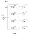
- FIG. 3is a schematic diagram of an electrosurgical system for treating tissue, according to an embodiment of the present disclosure.
- the electrosurgical system 300includes a microwave signal source 310 providing a microwave frequency output signal to a microwave power splitter 330 , and a first, a second, a third, and a fourth microwave ablation antenna assembly 370 A, 370 B, 370 C, and 370 C, each coupled to the microwave power splitter 330 .
- the microwave signal source 310is capable of generating a plurality of output signals of various frequencies that are input to the microwave power splitter 330 .
- the microwave power splitter 330includes a first quarter wavelength transmission line 350 A that electrically connects the first antenna assembly 370 A to the microwave signal source 310 , defining a first channel; a second quarter wavelength transmission line 350 B that electrically connects the second antenna assembly 370 B to the microwave signal source 310 , defining a second channel; a third quarter wavelength transmission line 350 C that electrically connects the third antenna assembly 370 C to the microwave signal source 310 , defining a third channel; and a fourth transmission line 350 D that electrically connects the fourth antenna assembly 370 D to the microwave signal source 310 , defining a fourth channel.
- Transmission lines 350 A, 350 B, 350 C, and 350 Deach include one or more electrically conductive elements, such as electrically conductive wires.
- transmission lines 350 A, 350 B, 350 C, and 350 Deach have substantially the same length, which preserves the phase relationship between electrical signals in each channel of the electrosurgical system 300 .
- Z inis the input impedance to the quarter wavelength transmission lines 350 A, 350 B, 350 C, and 350 D (e.g., the impedance at the microwave signal generator 310 )
- Z ois the characteristic impedance of the quarter wavelength transmission lines 350 A, 350 B, 350 C, and 350 D (e.g., the impedance at the microwave power splitter 330 )
- Z Lis the impedance of the antenna assemblies 370 A, 370 B, 370 C, 370 D.
- the characteristic impedance Z o of the transmission lines 350 A, 350 B, 350 C, and 350 Dis equal to 100 ohms, and the electrical length of the transmission lines 350 A, 350 B, 350 C, and 350 D is set to a quarter wavelength
- the electrosurgical system 300 illustrated in FIG. 3includes four microwave ablation antenna assemblies 370 A, 370 B, 370 C, and 370 D and four quarter wavelength transmission lines 350 A, 350 B, 350 C, and 350 D, it is to be understood that any N number of antenna assemblies and any N number of quarter wavelength transmission lines may be utilized.
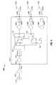
- FIG. 4is a schematic diagram of an electrosurgical system 400 for treating tissue, according to another embodiment of the present disclosure.
- the electrosurgical system 400 illustratedis a three-channel system that includes a microwave signal source 410 , a microwave amplifier 420 , a first, a second, and a third microwave ablation antenna assembly 470 A, 470 B, and 470 C, and a controller 430 that includes one input 432 and a first, a second, and a third output 434 A, 434 B, and 448 C.
- the electrosurgical system 400includes a first transmission line 475 A that electrically connects the first antenna assembly 470 A to the first output 434 A, defining a first channel; a second transmission line 475 B that electrically connects the second antenna assembly 470 A to the second output 434 B, defining a second channel; and a third transmission line 475 C that electrically connects the third antenna assembly 470 C to the third output 434 C, defining a third channel.
- the first, second, and third transmission lines 475 A, 475 B, and 475 Ceach include one or more electrically conductive elements, such as electrically conductive wires.
- the first, second, and third transmission lines 475 A, 475 B, and 475 Ceach have substantially the same length, which preserves the phase relationship between electrical signals in each channel of the electrosurgical system 400 .
- the microwave signal source 410provides a microwave frequency output signal to the amplifier 420 .
- the microwave amplifier 420provides an output signal through an output terminal that is electrically coupled to the input 432 of the controller 430 .
- Controller 430includes a first output-side directional coupler 465 A, a second output-side directional coupler 465 B, and a third output-side directional coupler 465 C.
- Output-side directional couplers 465 A, 465 B, 465 Care configured to measure power at each output 434 A, 434 B, 434 C, respectively, and to transmit a microwave signal, received as input, to antenna assemblies 470 A, 470 B, and 470 C.
- the controller 430includes a first isolator 422 electrically coupled between the input 432 and an input-side directional coupler 424 .
- the first isolator 422operates to appear as a fixed matching load to the microwave signal source 410 to prevent detuning thereof due to variations in load impedance caused by, for example, antenna assemblies 470 A, 470 B, and 470 C and/or transmission lines 475 A, 475 B, and 475 C.
- the first isolator 422transmits the microwave signal from the amplifier 420 to the input-side directional coupler 424 .
- the input-side directional coupler 424measures the microwave signal received from the amplifier 420 as input and transmits the microwave signal to a first switching device 440 electrically coupled thereto.
- the first switching device 440transmits the microwave signal to any one or more of a 1:2 power divider 450 , a 1:3 power divider 452 , and/or a second switching device 442 , individually or in any combination thereof.
- power divider 450Upon receiving the microwave signal from switching device 440 , power divider 450 divides the microwave signal as output between the second switching device 442 and a third switching device 444 . Upon receiving the microwave signal from switching device 440 , power divider 452 divides the microwave signal as output between the second switching device 442 , the third switching device 444 , and the third output-side directional coupler 465 C. The third output-side directional coupler 465 C powers antenna assembly 470 C by transmitting the microwave signal received from power divider 452 to the third output 434 C.
- the second switching device 442Upon receiving the microwave signal from any combination of the first switching device 440 , power divider 450 , and/or power divider 452 , the second switching device 442 transmits the microwave signal to the first output-side directional coupler 465 A.
- the first output-side directional coupler 465 Apowers antenna assembly 470 A by transmitting the microwave signal received from the second switching device 442 to the first output 434 A.
- the third switching device 444Upon receiving the microwave signal from any combination of power divider 450 and/or 452 , the third switching device 444 transmits the microwave signal to the second output-side directional coupler 465 B.
- the second output-side directional coupler 465 Bpowers antenna assembly 470 B by transmitting the microwave signal received from the third switching device 444 to the second output 434 B.
- the output power values corresponding to the three outputs 434 A, 434 B, and 434 C for a given power Pwill be either P, 0, and 0; P/2, P/2, and 0; or P/3, P/3, and P/3.
- Controller 430further includes a first isolator 460 A electrically coupled between the second switching device 442 and the first output-side directional coupler 465 A; a second isolator 460 B electrically coupled between the third switching device 444 and the second output-side directional coupler 465 B; and a third isolator 460 C electrically coupled between power divider 452 and the third output-side directional coupler 465 C.
- First, second, and third isolators 460 A, 460 B, and 460 Care configured to appear as a fixed matching load to the microwave signal generator 410 to prevent detuning thereof due to variations in load impedance caused by, for example, antenna assemblies 470 A, 470 B, and 470 C and/or transmission lines 475 A, 475 B, and 475 C.
- Switching devices 440 , 442 , 444may be any suitable switching device configured to output power to a load connected thereto based on more than one inputs such as, for example, a single pole double throw switch (SPDT), a single pole triple throw switch (SP3T), etc.
- SPDTsingle pole double throw switch
- SP3Tsingle pole triple throw switch
- any one or more of isolator 422 and isolators 460 A, 460 B, 460 Cmay be a three-port circulator, as is known in the art, having one of its three ports terminated in a fixed matching load to the microwave signal source 410 to effectively operate substantially as described above with reference to isolator 422 and/or isolators 460 A, 460 B, 460 C.
- the controller 430may include one or more phase detectors (not shown) to compare the respective phases of electrical signals inputted through the input 432 . By comparing a reference signal, such as a clock signal, to a feedback signal using a phase detector, phase adjustments may be made based on the comparison of the electrical signals inputted, to set the phase relationship between electrical signals in each channel of the electrosurgical system 400 .
- phase detectorsnot shown
- the controller 440delivers phase-controlled microwave power through the outputs 434 A, 434 B and 434 C to the antenna assemblies 470 A, 470 B and 470 C, respectively, irrespective of the phase of the electrical signal inputted through the input 432 .
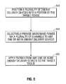
- FIG. 5is a flowchart illustrating a method for providing energy to a target tissue, according to an embodiment of the present disclosure.
- a plurality of energy delivery devicesare positioned into a portion of the target tissue.
- the energy delivery devicesmay be implemented using any suitable electrosurgical instruments or devices, such as, for example, the device 130 , according to embodiments of the present disclosure described in connection with FIG. 1 .
- the energy delivery devicesare positioned into a portion of a target site on the tissue or adjacent to a portion of a target site on the tissue.
- the energy delivery devicesare inserted directly into tissue, inserted through a lumen, such as a vein, needle or catheter, placed into the body during surgery by a clinician or positioned in the body by other suitable methods.
- the energy delivery devicesinclude any suitable antenna assemblies for the delivery of electromagnetic radiation, such as, for example, the antenna assemblies 270 A, 270 B and 270 C, according to embodiments of the present disclosure described in connection with FIG. 2 .
- microwave energy from any one or more energy delivery devicesis applied to the target tissue.
Landscapes
- Health & Medical Sciences (AREA)
- Life Sciences & Earth Sciences (AREA)
- Biomedical Technology (AREA)
- Engineering & Computer Science (AREA)
- Surgery (AREA)
- Animal Behavior & Ethology (AREA)
- General Health & Medical Sciences (AREA)
- Nuclear Medicine, Radiotherapy & Molecular Imaging (AREA)
- Veterinary Medicine (AREA)
- Public Health (AREA)
- Heart & Thoracic Surgery (AREA)
- Molecular Biology (AREA)
- Physics & Mathematics (AREA)
- Medical Informatics (AREA)
- Otolaryngology (AREA)
- Electromagnetism (AREA)
- Pathology (AREA)
- Radiology & Medical Imaging (AREA)
- Surgical Instruments (AREA)
Abstract
Description
Zin=Zo2/ZL (1)
4*Zin=Zo2/ZL (2)
Zo=2*Zin (3)
Claims (11)
Priority Applications (3)
| Application Number | Priority Date | Filing Date | Title |
|---|---|---|---|
| US15/005,479US9554855B2 (en) | 2009-09-18 | 2016-01-25 | Tissue ablation system with energy distribution |
| US15/418,834US10016237B2 (en) | 2009-09-18 | 2017-01-30 | Tissue ablation system with energy distribution |
| US16/030,309US11039885B2 (en) | 2009-09-18 | 2018-07-09 | Tissue ablation system with energy distribution |
Applications Claiming Priority (3)
| Application Number | Priority Date | Filing Date | Title |
|---|---|---|---|
| US12/562,842US9095359B2 (en) | 2009-09-18 | 2009-09-18 | Tissue ablation system with energy distribution |
| US14/691,710US9375278B2 (en) | 2009-09-18 | 2015-04-21 | Tissue ablation system with energy distribution |
| US15/005,479US9554855B2 (en) | 2009-09-18 | 2016-01-25 | Tissue ablation system with energy distribution |
Related Parent Applications (1)
| Application Number | Title | Priority Date | Filing Date |
|---|---|---|---|
| US14/691,710ContinuationUS9375278B2 (en) | 2009-09-18 | 2015-04-21 | Tissue ablation system with energy distribution |
Related Child Applications (1)
| Application Number | Title | Priority Date | Filing Date |
|---|---|---|---|
| US15/418,834ContinuationUS10016237B2 (en) | 2009-09-18 | 2017-01-30 | Tissue ablation system with energy distribution |
Publications (2)
| Publication Number | Publication Date |
|---|---|
| US20160135886A1 US20160135886A1 (en) | 2016-05-19 |
| US9554855B2true US9554855B2 (en) | 2017-01-31 |
Family
ID=43432243
Family Applications (5)
| Application Number | Title | Priority Date | Filing Date |
|---|---|---|---|
| US12/562,842Active2032-11-12US9095359B2 (en) | 2009-09-18 | 2009-09-18 | Tissue ablation system with energy distribution |
| US14/691,710ActiveUS9375278B2 (en) | 2009-09-18 | 2015-04-21 | Tissue ablation system with energy distribution |
| US15/005,479ActiveUS9554855B2 (en) | 2009-09-18 | 2016-01-25 | Tissue ablation system with energy distribution |
| US15/418,834ActiveUS10016237B2 (en) | 2009-09-18 | 2017-01-30 | Tissue ablation system with energy distribution |
| US16/030,309Expired - Fee RelatedUS11039885B2 (en) | 2009-09-18 | 2018-07-09 | Tissue ablation system with energy distribution |
Family Applications Before (2)
| Application Number | Title | Priority Date | Filing Date |
|---|---|---|---|
| US12/562,842Active2032-11-12US9095359B2 (en) | 2009-09-18 | 2009-09-18 | Tissue ablation system with energy distribution |
| US14/691,710ActiveUS9375278B2 (en) | 2009-09-18 | 2015-04-21 | Tissue ablation system with energy distribution |
Family Applications After (2)
| Application Number | Title | Priority Date | Filing Date |
|---|---|---|---|
| US15/418,834ActiveUS10016237B2 (en) | 2009-09-18 | 2017-01-30 | Tissue ablation system with energy distribution |
| US16/030,309Expired - Fee RelatedUS11039885B2 (en) | 2009-09-18 | 2018-07-09 | Tissue ablation system with energy distribution |
Country Status (3)
| Country | Link |
|---|---|
| US (5) | US9095359B2 (en) |
| EP (1) | EP2298210A1 (en) |
| JP (1) | JP2011062520A (en) |
Cited By (1)
| Publication number | Priority date | Publication date | Assignee | Title |
|---|---|---|---|---|
| US20170135762A1 (en)* | 2009-09-18 | 2017-05-18 | Covidien Lp | Tissue ablation system with energy distribution |
Families Citing this family (46)
| Publication number | Priority date | Publication date | Assignee | Title |
|---|---|---|---|---|
| US7258690B2 (en) | 2003-03-28 | 2007-08-21 | Relievant Medsystems, Inc. | Windowed thermal ablation probe |
| US8361067B2 (en) | 2002-09-30 | 2013-01-29 | Relievant Medsystems, Inc. | Methods of therapeutically heating a vertebral body to treat back pain |
| US6907884B2 (en) | 2002-09-30 | 2005-06-21 | Depay Acromed, Inc. | Method of straddling an intraosseous nerve |
| US7553309B2 (en) | 2004-10-08 | 2009-06-30 | Covidien Ag | Electrosurgical system employing multiple electrodes and method thereof |
| US20100030206A1 (en)* | 2008-07-29 | 2010-02-04 | Brannan Joseph D | Tissue Ablation System With Phase-Controlled Channels |
| US10028753B2 (en) | 2008-09-26 | 2018-07-24 | Relievant Medsystems, Inc. | Spine treatment kits |
| CA2737374C (en) | 2008-09-26 | 2017-03-28 | Relievant Medsystems, Inc. | Systems and methods for navigating an instrument through bone |
| US8323275B2 (en) | 2009-06-19 | 2012-12-04 | Vivant Medical, Inc. | Laparoscopic port with microwave rectifier |
| US9113925B2 (en)* | 2009-09-09 | 2015-08-25 | Covidien Lp | System and method for performing an ablation procedure |
| US8069553B2 (en) | 2009-09-09 | 2011-12-06 | Vivant Medical, Inc. | Method for constructing a dipole antenna |
| US8568398B2 (en) | 2009-09-29 | 2013-10-29 | Covidien Lp | Flow rate monitor for fluid cooled microwave ablation probe |
| US9113926B2 (en) | 2009-09-29 | 2015-08-25 | Covidien Lp | Management of voltage standing wave ratio at skin surface during microwave ablation |
| US8568401B2 (en) | 2009-10-27 | 2013-10-29 | Covidien Lp | System for monitoring ablation size |
| US8430871B2 (en) | 2009-10-28 | 2013-04-30 | Covidien Lp | System and method for monitoring ablation size |
| US8382750B2 (en)* | 2009-10-28 | 2013-02-26 | Vivant Medical, Inc. | System and method for monitoring ablation size |
| US8394092B2 (en)* | 2009-11-17 | 2013-03-12 | Vivant Medical, Inc. | Electromagnetic energy delivery devices including an energy applicator array and electrosurgical systems including same |
| US8764744B2 (en) | 2010-01-25 | 2014-07-01 | Covidien Lp | System for monitoring ablation size |
| US8491579B2 (en) | 2010-02-05 | 2013-07-23 | Covidien Lp | Electrosurgical devices with choke shorted to biological tissue |
| US8968288B2 (en) | 2010-02-19 | 2015-03-03 | Covidien Lp | Ablation devices with dual operating frequencies, systems including same, and methods of adjusting ablation volume using same |
| US8617153B2 (en) | 2010-02-26 | 2013-12-31 | Covidien Lp | Tunable microwave ablation probe |
| US8728067B2 (en) | 2010-03-08 | 2014-05-20 | Covidien Lp | Microwave antenna probe having a deployable ground plane |
| US10039601B2 (en) | 2010-03-26 | 2018-08-07 | Covidien Lp | Ablation devices with adjustable radiating section lengths, electrosurgical systems including same, and methods of adjusting ablation fields using same |
| US8409188B2 (en) | 2010-03-26 | 2013-04-02 | Covidien Lp | Ablation devices with adjustable radiating section lengths, electrosurgical systems including same, and methods of adjusting ablation fields using same |
| US9192436B2 (en) | 2010-05-25 | 2015-11-24 | Covidien Lp | Flow rate verification monitor for fluid-cooled microwave ablation probe |
| US8652127B2 (en) | 2010-05-26 | 2014-02-18 | Covidien Lp | System and method for chemically cooling an ablation antenna |
| US9241762B2 (en) | 2010-06-03 | 2016-01-26 | Covidien Lp | Specific absorption rate measurement and energy-delivery device characterization using image analysis |
| US8672933B2 (en) | 2010-06-30 | 2014-03-18 | Covidien Lp | Microwave antenna having a reactively-loaded loop configuration |
| US10588684B2 (en) | 2010-07-19 | 2020-03-17 | Covidien Lp | Hydraulic conductivity monitoring to initiate tissue division |
| US9028476B2 (en) | 2011-02-03 | 2015-05-12 | Covidien Lp | Dual antenna microwave resection and ablation device, system and method of use |
| EP2514382A1 (en)* | 2011-04-21 | 2012-10-24 | Koninklijke Philips Electronics N.V. | MR imaging guided therapy system |
| JP5979845B2 (en)* | 2011-10-25 | 2016-08-31 | 株式会社 オリエントマイクロウェーブ | Microwave surgical device and device including microwave surgical device |
| AU2012362524B2 (en) | 2011-12-30 | 2018-12-13 | Relievant Medsystems, Inc. | Systems and methods for treating back pain |
| US8943744B2 (en)* | 2012-02-17 | 2015-02-03 | Nathaniel L. Cohen | Apparatus for using microwave energy for insect and pest control and methods thereof |
| US10588691B2 (en) | 2012-09-12 | 2020-03-17 | Relievant Medsystems, Inc. | Radiofrequency ablation of tissue within a vertebral body |
| WO2014071161A1 (en) | 2012-11-05 | 2014-05-08 | Relievant Medsystems, Inc. | System and methods for creating curved paths through bone and modulating nerves within the bone |
| US9724151B2 (en) | 2013-08-08 | 2017-08-08 | Relievant Medsystems, Inc. | Modulating nerves within bone using bone fasteners |
| AU2015374244B2 (en) | 2014-12-31 | 2019-11-21 | Covidien Lp | System and method for treating COPD and emphysema |
| GB2559595B (en)* | 2017-02-10 | 2021-09-01 | Creo Medical Ltd | Electrosurgical apparatus and electrosurgical instrument |
| US10959674B2 (en) | 2017-10-23 | 2021-03-30 | Datafeel Inc. | Communication devices, methods, and systems |
| US11103308B2 (en) | 2017-12-11 | 2021-08-31 | Covidien Lp | Reusable transmission network for dividing energy and monitoring signals between surgical devices |
| AU2020346827A1 (en) | 2019-09-12 | 2022-03-31 | Relievant Medsystems, Inc. | Systems and methods for tissue modulation |
| EP4117562B1 (en)* | 2020-03-13 | 2025-05-21 | Biocompatibles UK Limited | Ramping up function for microwave ablation devices |
| US12082876B1 (en) | 2020-09-28 | 2024-09-10 | Relievant Medsystems, Inc. | Introducer drill |
| US11934583B2 (en) | 2020-10-30 | 2024-03-19 | Datafeel Inc. | Wearable data communication apparatus, kits, methods, and systems |
| EP4268150A4 (en) | 2020-12-22 | 2024-12-18 | Relievant Medsystems, Inc. | PREDICTION OF CANDIDATES FOR SPINAL NEUROMODULATION |
| US12433668B1 (en) | 2021-11-08 | 2025-10-07 | Relievant Medsystems, Inc. | Impedance stoppage mitigation during radiofrequency tissue ablation procedures |
Citations (149)
| Publication number | Priority date | Publication date | Assignee | Title |
|---|---|---|---|---|
| DE390937C (en) | 1922-10-13 | 1924-03-03 | Adolf Erb | Device for internal heating of furnace furnaces for hardening, tempering, annealing, quenching and melting |
| DE1099658B (en) | 1959-04-29 | 1961-02-16 | Siemens Reiniger Werke Ag | Automatic switch-on device for high-frequency surgical devices |
| FR1275415A (en) | 1960-09-26 | 1961-11-10 | Device for detecting disturbances for electrical installations, in particular electrosurgery | |
| DE1139927B (en) | 1961-01-03 | 1962-11-22 | Friedrich Laber | High-frequency surgical device |
| DE1149832B (en) | 1961-02-25 | 1963-06-06 | Siemens Reiniger Werke Ag | High frequency surgical apparatus |
| FR1347865A (en) | 1962-11-22 | 1964-01-04 | Improvements to diathermo-coagulation devices | |
| DE1439302A1 (en) | 1963-10-26 | 1969-01-23 | Siemens Ag | High-frequency surgical device |
| SU401367A1 (en) | 1971-10-05 | 1973-10-12 | Тернопольский государственный медицинский институт | BIAKTIVNYE ELECTRO SURGICAL INSTRUMENT |
| FR2235669A1 (en) | 1973-07-07 | 1975-01-31 | Lunacek Boris | Gynaecological sterilisation instrument - has hollow electrode protruding from the end of a curved ended tube |
| DE2439587A1 (en) | 1973-08-23 | 1975-02-27 | Matburn Holdings Ltd | ELECTROSURGICAL DEVICE |
| DE2455174A1 (en) | 1973-11-21 | 1975-05-22 | Termiflex Corp | INPUT / OUTPUT DEVICE FOR DATA EXCHANGE WITH DATA PROCESSING DEVICES |
| DE2407559A1 (en) | 1974-02-16 | 1975-08-28 | Dornier System Gmbh | Tissue heat treatment probe - has water cooling system which ensures heat development only in treated tissues |
| DE2415263A1 (en) | 1974-03-29 | 1975-10-02 | Aesculap Werke Ag | Surgical H.F. coagulation probe has electrode tongs - with exposed ends of insulated conductors forming tong-jaws |
| DE2429021A1 (en) | 1974-06-18 | 1976-01-08 | Erbe Elektromedizin | Remote control for HF surgical instruments - uses cable with two conductors at most |
| FR2276027A1 (en) | 1974-06-25 | 1976-01-23 | Medical Plastics Inc | Plate electrode with connector - is clamped between connector jaws held by releasable locking device |
| DE2460481A1 (en) | 1974-12-20 | 1976-06-24 | Delma Elektro Med App | Electrode grip for remote HF surgical instrument switching - has shaped insulated piece with contact ring of sterilizable (silicon) rubber |
| DE2602517A1 (en) | 1975-01-23 | 1976-07-29 | Dentsply Int Inc | ELECTROSURGICAL DEVICE |
| DE2504280A1 (en) | 1975-02-01 | 1976-08-05 | Hans Heinrich Prof Dr Meinke | DEVICE FOR ELECTRIC TISSUE CUTTING IN SURGERY |
| FR2313708A1 (en) | 1975-06-02 | 1976-12-31 | Sybron Corp | Electro surgical instrument impulse control circuit - has potentiometer between patient electrodes and threshold switch for excessive voltage |
| DE2627679A1 (en) | 1975-06-26 | 1977-01-13 | Marcel Lamidey | HEMATISTIC HIGH FREQUENCY EXTRACTOR FORCEPS |
| DE2540968A1 (en) | 1975-09-13 | 1977-03-17 | Erbe Elektromedizin | Circuit for bipolar coagulation tweezers - permits preparation of tissues prior to coagulation |
| DE2820908A1 (en) | 1977-05-16 | 1978-11-23 | Joseph Skovajsa | DEVICE FOR THE LOCAL TREATMENT OF A PATIENT IN PARTICULAR FOR ACUPUNCTURE OR AURICULAR THERAPY |
| DE2803275A1 (en) | 1978-01-26 | 1979-08-02 | Aesculap Werke Ag | HF surgical appts. with active treatment and patient electrodes - has sensor switching generator to small voltage when hand-operated switch is closed |
| DE2823291A1 (en) | 1978-05-27 | 1979-11-29 | Rainer Ing Grad Koch | Coagulation instrument automatic HF switching circuit - has first lead to potentiometer and second to transistor base |
| SU727201A2 (en) | 1977-11-02 | 1980-04-15 | Киевский Научно-Исследовательский Институт Нейрохирургии | Electric surgical apparatus |
| DE2946728A1 (en) | 1979-11-20 | 1981-05-27 | Erbe Elektromedizin GmbH & Co KG, 7400 Tübingen | HF surgical appts. for use with endoscope - provides cutting or coagulation current at preset intervals and of selected duration |
| US4292960A (en) | 1979-04-30 | 1981-10-06 | Rca Corporation | Apparatus and method for application of radioactive and microwave energy to the body |
| DE3143421A1 (en) | 1980-11-04 | 1982-05-27 | The Agency of Industrial Science and Technology, Tokyo | Laser scalpel |
| DE3045996A1 (en) | 1980-12-05 | 1982-07-08 | Medic Eschmann Handelsgesellschaft für medizinische Instrumente mbH, 2000 Hamburg | Electro-surgical scalpel instrument - has power supply remotely controlled by surgeon |
| FR2502935A1 (en) | 1981-03-31 | 1982-10-08 | Dolley Roger | Diathermic knife for coagulating tissues - has monitoring current added to HF coagulating current in order to control end of operation as function or resistance of coagulating tissues |
| DE3120102A1 (en) | 1981-05-20 | 1982-12-09 | F.L. Fischer GmbH & Co, 7800 Freiburg | ARRANGEMENT FOR HIGH-FREQUENCY COAGULATION OF EGG WHITE FOR SURGICAL PURPOSES |
| FR2517953A1 (en) | 1981-12-10 | 1983-06-17 | Alvar Electronic | Diaphanometer for optical examination of breast tissue structure - measures tissue transparency using two plates and optical fibre bundle cooperating with photoelectric cells |
| US4448198A (en) | 1979-06-19 | 1984-05-15 | Bsd Medical Corporation | Invasive hyperthermia apparatus and method |
| FR2573301A1 (en) | 1984-11-16 | 1986-05-23 | Lamidey Gilles | Surgical forceps and its control and monitoring apparatus |
| DE3510586A1 (en) | 1985-03-23 | 1986-10-02 | Erbe Elektromedizin GmbH, 7400 Tübingen | Control device for a high-frequency surgical instrument |
| US4632128A (en) | 1985-06-17 | 1986-12-30 | Rca Corporation | Antenna apparatus for scanning hyperthermia |
| US4672980A (en) | 1980-04-02 | 1987-06-16 | Bsd Medical Corporation | System and method for creating hyperthermia in tissue |
| DE3604823A1 (en) | 1986-02-15 | 1987-08-27 | Flachenecker Gerhard | HIGH FREQUENCY GENERATOR WITH AUTOMATIC PERFORMANCE CONTROL FOR HIGH FREQUENCY SURGERY |
| EP0246350A1 (en) | 1986-05-23 | 1987-11-25 | Erbe Elektromedizin GmbH. | Coagulation electrode |
| DE8712328U1 (en) | 1987-09-11 | 1988-02-18 | Jakoubek, Franz, 7201 Emmingen-Liptingen | Endoscopy forceps |
| US4741348A (en) | 1984-07-31 | 1988-05-03 | Tokyo Keiki Co., Ltd. | Heating apparatus for hyperthermia |
| DE3711511C1 (en) | 1987-04-04 | 1988-06-30 | Hartmann & Braun Ag | Method for determining gas concentrations in a gas mixture and sensor for measuring thermal conductivity |
| US4798215A (en)* | 1984-03-15 | 1989-01-17 | Bsd Medical Corporation | Hyperthermia apparatus |
| US4815479A (en) | 1986-08-13 | 1989-03-28 | M/A Com, Inc. | Hyperthermia treatment method and apparatus |
| US4860752A (en) | 1988-02-18 | 1989-08-29 | Bsd Medical Corporation | Invasive microwave array with destructive and coherent phase |
| DE3904558A1 (en) | 1989-02-15 | 1990-08-23 | Flachenecker Gerhard | Radio-frequency generator with automatic power control for radio-frequency surgery |
| DE3942998A1 (en) | 1989-12-27 | 1991-07-04 | Delma Elektro Med App | Electro-surgical HF instrument for contact coagulation - has monitoring circuit evaluating HF voltage at electrodes and delivering switch=off signal |
| US5097844A (en) | 1980-04-02 | 1992-03-24 | Bsd Medical Corporation | Hyperthermia apparatus having three-dimensional focusing |
| EP0521264A2 (en) | 1991-07-03 | 1993-01-07 | W.L. Gore & Associates GmbH | Antenna device with feed |
| JPH055106Y2 (en) | 1986-02-28 | 1993-02-09 | ||
| DE4238263A1 (en) | 1991-11-15 | 1993-05-19 | Minnesota Mining & Mfg | Adhesive comprising hydrogel and crosslinked polyvinyl:lactam - is used in electrodes for biomedical application providing low impedance and good mechanical properties when water and/or moisture is absorbed from skin |
| EP0556705A1 (en) | 1992-02-20 | 1993-08-25 | DELMA ELEKTRO-UND MEDIZINISCHE APPARATEBAU GESELLSCHAFT mbH | High frequency surgery device |
| EP0558429A1 (en) | 1992-02-26 | 1993-09-01 | PECHINEY RECHERCHE (Groupement d'Intérêt Economique géré par l'ordonnance no. 67-821 du 23 Septembre 1967) | Method of simultaneous measuring of electrical resistivety and thermal conductivity |
| JPH0540112Y2 (en) | 1987-03-03 | 1993-10-12 | ||
| JPH06503028A (en) | 1991-07-26 | 1994-04-07 | ユニベールシテデスジャンス エ テクノロジー ドウ リル | Internal processing system for special bodies and how to use it |
| JPH06343644A (en) | 1993-05-04 | 1994-12-20 | Gyrus Medical Ltd | Surgical peritoneoscope equipment |
| DE4339049A1 (en) | 1993-11-16 | 1995-05-18 | Erbe Elektromedizin | Surgical system and instruments configuration device |
| JPH07265328A (en) | 1993-11-01 | 1995-10-17 | Gyrus Medical Ltd | Electrode assembly for electric surgery device and electric surgery device using it |
| JPH0856955A (en) | 1994-06-29 | 1996-03-05 | Gyrus Medical Ltd | Electric surgical apparatus |
| JPH08252263A (en) | 1994-12-21 | 1996-10-01 | Gyrus Medical Ltd | Electronic surgical incision instrument and electronic surgical incision device using the same |
| DE29616210U1 (en) | 1996-09-18 | 1996-11-14 | Olympus Winter & Ibe Gmbh, 22045 Hamburg | Handle for surgical instruments |
| JPH0910223A (en) | 1995-06-23 | 1997-01-14 | Gyrus Medical Ltd | Generator and system for electric operation |
| DE19608716C1 (en) | 1996-03-06 | 1997-04-17 | Aesculap Ag | Bipolar surgical holding instrument |
| EP0836868A2 (en) | 1996-10-18 | 1998-04-22 | Gebr. Berchtold GmbH & Co. | High frequency surgical apparatus and method for operating same |
| DE19751106A1 (en) | 1996-11-27 | 1998-05-28 | Eastman Kodak Co | Laser printer with array of laser diodes |
| DE19717411A1 (en) | 1997-04-25 | 1998-11-05 | Aesculap Ag & Co Kg | Monitoring of thermal loading of patient tissue in contact region of neutral electrode of HF treatment unit |
| DE19751108A1 (en) | 1997-11-18 | 1999-05-20 | Beger Frank Michael Dipl Desig | Electrosurgical operation tool, especially for diathermy |
| DE19801173C1 (en) | 1998-01-15 | 1999-07-15 | Kendall Med Erzeugnisse Gmbh | Clamp connector for film electrodes |
| JPH11244298A (en) | 1997-12-19 | 1999-09-14 | Gyrus Medical Ltd | Electric surgical instrument |
| DE19848540A1 (en) | 1998-10-21 | 2000-05-25 | Reinhard Kalfhaus | Circuit layout and method for operating a single- or multiphase current inverter connects an AC voltage output to a primary winding and current and a working resistance to a transformer's secondary winding and current. |
| JP2000342599A (en) | 1999-05-21 | 2000-12-12 | Gyrus Medical Ltd | Generator for electrosurgical operation, electrosurgical operation system, method for operating this system and method for performing amputation and resection of tissue by electrosurgical operation |
| JP2000350732A (en) | 1999-05-21 | 2000-12-19 | Gyrus Medical Ltd | Electrosurgical system, generator for electrosurgery, and method for cutting or excising tissue by electrosurgery |
| US6208903B1 (en)* | 1995-06-07 | 2001-03-27 | Medical Contouring Corporation | Microwave applicator |
| US6347251B1 (en)* | 1999-12-23 | 2002-02-12 | Tianquan Deng | Apparatus and method for microwave hyperthermia and acupuncture |
| EP1159926A3 (en) | 2000-06-03 | 2003-03-19 | Aesculap Ag | Scissor- or forceps-like surgical instrument |
| DE10224154A1 (en) | 2002-05-27 | 2003-12-18 | Celon Ag Medical Instruments | Application device for electrosurgical device for body tissue removal via of HF current has electrode subset selected from active electrode set in dependence on measured impedance of body tissue |
| DE10328514B3 (en) | 2003-06-20 | 2005-03-03 | Aesculap Ag & Co. Kg | Endoscopic surgical scissor instrument has internal pushrod terminating at distal end in transverse cylindrical head |
| FR2862813A1 (en) | 2003-11-20 | 2005-05-27 | Pellenc Sa | METHOD FOR BALANCED LOADING OF LITHIUM-ION OR POLYMER LITHIUM BATTERY |
| FR2864439A1 (en) | 2003-12-30 | 2005-07-01 | Image Guided Therapy | Tumor treating device for use by surgeon, has generator applying voltage to each of active electrodes in manner independent from other electrodes and having sinusoidal voltage generation unit adjusting amplitude and phase of voltage |
| DE102004022206A1 (en) | 2004-05-04 | 2005-12-01 | Bundesrepublik Deutschland, vertr. d. d. Bundesministerium für Wirtschaft und Arbeit, dieses vertr. d. d. Präsidenten der Physikalisch-Technischen Bundesanstalt | Sensor for measuring thermal conductivity comprises a strip composed of two parallel sections, and two outer heating strips |
| DE202005015147U1 (en) | 2005-09-26 | 2006-02-09 | Health & Life Co., Ltd., Chung-Ho | Biosensor test strip with identifying function for biological measuring instruments has functioning electrode and counter electrode, identification zones with coating of electrically conductive material and reaction zone |
| US20060200120A1 (en)* | 2005-03-07 | 2006-09-07 | Scimed Life Systems, Inc. | Apparatus for switching nominal and attenuated power between ablation probes |
| US7128739B2 (en) | 2001-11-02 | 2006-10-31 | Vivant Medical, Inc. | High-strength microwave antenna assemblies and methods of use |
| US7197363B2 (en) | 2002-04-16 | 2007-03-27 | Vivant Medical, Inc. | Microwave antenna having a curved configuration |
| US7294127B2 (en) | 2002-03-05 | 2007-11-13 | Baylis Medical Company Inc. | Electrosurgical tissue treatment method |
| US20080147056A1 (en) | 2006-07-14 | 2008-06-19 | Micrablate | Energy delivery systems and uses thereof |
| US20090306652A1 (en) | 2008-06-09 | 2009-12-10 | Buysse Steven P | Ablation Needle Guide |
| US20090326620A1 (en) | 2008-06-26 | 2009-12-31 | Francesca Rossetto | Deployable Microwave Antenna for Treating Tissue |
| EP2149343A2 (en) | 2008-07-29 | 2010-02-03 | Vivant Medical, Inc. | Tissue ablatoin system with phase-controlled channels |
| US20100030210A1 (en) | 2008-08-01 | 2010-02-04 | Paulus Joseph A | Polyphase Electrosurgical System and Method |
| US20100045559A1 (en) | 2008-08-25 | 2010-02-25 | Vivant Medical, Inc. | Dual-Band Dipole Microwave Ablation Antenna |
| US20100045558A1 (en) | 2008-08-25 | 2010-02-25 | Vivant Medical, Inc. | Dual-Band Dipole Microwave Ablation Antenna |
| US20100076422A1 (en) | 2008-09-24 | 2010-03-25 | Tyco Healthcare Group Lp | Thermal Treatment of Nucleus Pulposus |
| US20100087808A1 (en) | 2008-10-03 | 2010-04-08 | Vivant Medical, Inc. | Combined Frequency Microwave Ablation System, Devices and Methods of Use |
| US20100094273A1 (en) | 2008-10-13 | 2010-04-15 | Vivant Medical, Inc. | Antenna Assemblies for Medical Applications |
| US20100092939A1 (en) | 2008-10-15 | 2010-04-15 | Tyco Healthcare Group Lp | System and Method for Perfusing Biological Organs |
| US20100097284A1 (en) | 2008-10-17 | 2010-04-22 | Vivant Medical, Inc. | Choked Dielectric Loaded Tip Dipole Microwave Antenna |
| US7749011B2 (en) | 2007-11-27 | 2010-07-06 | Vivant Medical, Inc. | Floating connector for microwave surgical device |
| US20100256624A1 (en) | 2009-04-01 | 2010-10-07 | Vivant Medical, Inc. | Microwave Ablation System with User-Controlled Ablation Size and Method of Use |
| US20100262134A1 (en) | 2009-04-14 | 2010-10-14 | Vivant Medical, Inc. | Frequency Identification for Microwave Ablation Probes |
| US20100331834A1 (en) | 2009-06-29 | 2010-12-30 | Vivant Medical,Inc. | Ablation Probe Fixation |
| US7863984B1 (en) | 2009-07-17 | 2011-01-04 | Vivant Medical, Inc. | High efficiency microwave amplifier |
| US20110054458A1 (en) | 2009-08-25 | 2011-03-03 | Vivan Medical, Inc. | Microwave Ablation with Tissue Temperature Monitoring |
| US20110054459A1 (en) | 2009-08-27 | 2011-03-03 | Vivant Medical, Inc. | Ecogenic Cooled Microwave Ablation Antenna |
| US20110060326A1 (en) | 2009-09-09 | 2011-03-10 | Vivant Medical, Inc. | System and Method for Performing an Ablation Procedure |
| US20110071511A1 (en) | 2009-09-18 | 2011-03-24 | Vivant Medical, Inc. | System and Method for Checking High Power Microwave Ablation System Status on Startup |
| US20110071512A1 (en) | 2009-09-18 | 2011-03-24 | Vivant Medical, Inc. | Tissue Ablation System with Energy Distribution |
| US20110077636A1 (en) | 2009-09-29 | 2011-03-31 | Vivant Medical, Inc. | Management of Voltage Standing Wave Ratio at Skin Surface During Microwave Ablation |
| US20110118731A1 (en) | 2009-11-16 | 2011-05-19 | Tyco Healthcare Group Lp | Multi-Phase Electrode |
| US8035570B2 (en) | 2001-11-02 | 2011-10-11 | Vivant Medical, Inc. | High-strength microwave antenna assemblies |
| US8038693B2 (en) | 2009-10-21 | 2011-10-18 | Tyco Healthcare Group Ip | Methods for ultrasonic tissue sensing and feedback |
| US8059059B2 (en) | 2008-05-29 | 2011-11-15 | Vivant Medical, Inc. | Slidable choke microwave antenna |
| US8118808B2 (en) | 2009-03-10 | 2012-02-21 | Vivant Medical, Inc. | Cooled dielectrically buffered microwave dipole antenna |
| US8182480B2 (en) | 2008-08-19 | 2012-05-22 | Tyco Healthcare Group Lp | Insulated tube for suction coagulator |
| US8192427B2 (en) | 2008-06-09 | 2012-06-05 | Tyco Healthcare Group Lp | Surface ablation process with electrode cooling methods |
| US8197473B2 (en) | 2009-02-20 | 2012-06-12 | Vivant Medical, Inc. | Leaky-wave antennas for medical applications |
| US8202270B2 (en) | 2009-02-20 | 2012-06-19 | Vivant Medical, Inc. | Leaky-wave antennas for medical applications |
| US8211098B2 (en) | 2008-08-25 | 2012-07-03 | Vivant Medical, Inc. | Microwave antenna assembly having a dielectric body portion with radial partitions of dielectric material |
| US8216227B2 (en) | 2009-05-06 | 2012-07-10 | Vivant Medical, Inc. | Power-stage antenna integrated system with junction member |
| US8221418B2 (en) | 2008-02-07 | 2012-07-17 | Tyco Healthcare Group Lp | Endoscopic instrument for tissue identification |
| US8235981B2 (en) | 2009-06-02 | 2012-08-07 | Vivant Medical, Inc. | Electrosurgical devices with directional radiation pattern |
| US8251987B2 (en) | 2008-08-28 | 2012-08-28 | Vivant Medical, Inc. | Microwave antenna |
| US8282632B2 (en) | 2009-09-28 | 2012-10-09 | Vivant Medical, Inc. | Feedpoint optimization for microwave ablation dipole antenna with integrated tip |
| US8292881B2 (en) | 2009-05-27 | 2012-10-23 | Vivant Medical, Inc. | Narrow gauge high strength choked wet tip microwave ablation antenna |
| US8328801B2 (en) | 2009-08-17 | 2012-12-11 | Vivant Medical, Inc. | Surface ablation antenna with dielectric loading |
| US8328800B2 (en) | 2009-08-05 | 2012-12-11 | Vivant Medical, Inc. | Directive window ablation antenna with dielectric loading |
| US8328799B2 (en) | 2009-08-05 | 2012-12-11 | Vivant Medical, Inc. | Electrosurgical devices having dielectric loaded coaxial aperture with distally positioned resonant structure |
| US8334812B2 (en) | 2009-06-19 | 2012-12-18 | Vivant Medical, Inc. | Microwave ablation antenna radiation detector |
| US8343145B2 (en) | 2009-09-28 | 2013-01-01 | Vivant Medical, Inc. | Microwave surface ablation using conical probe |
| US8355803B2 (en) | 2009-09-16 | 2013-01-15 | Vivant Medical, Inc. | Perfused core dielectrically loaded dipole microwave antenna probe |
| US8353903B2 (en) | 2009-05-06 | 2013-01-15 | Vivant Medical, Inc. | Power-stage antenna integrated system |
| US8382750B2 (en) | 2009-10-28 | 2013-02-26 | Vivant Medical, Inc. | System and method for monitoring ablation size |
| US8394086B2 (en) | 2008-09-03 | 2013-03-12 | Vivant Medical, Inc. | Microwave shielding apparatus |
| US8394087B2 (en) | 2009-09-24 | 2013-03-12 | Vivant Medical, Inc. | Optical detection of interrupted fluid flow to ablation probe |
| US8394092B2 (en) | 2009-11-17 | 2013-03-12 | Vivant Medical, Inc. | Electromagnetic energy delivery devices including an energy applicator array and electrosurgical systems including same |
| US8409187B2 (en) | 2009-09-08 | 2013-04-02 | Covidien Lp | Microwave antenna probe with high-strength ceramic coupler |
| US8430871B2 (en) | 2009-10-28 | 2013-04-30 | Covidien Lp | System and method for monitoring ablation size |
| US8463396B2 (en) | 2009-05-06 | 2013-06-11 | Covidien LLP | Power-stage antenna integrated system with high-strength shaft |
| US8512328B2 (en) | 2008-10-13 | 2013-08-20 | Covidien Lp | Antenna assemblies for medical applications |
| US8545493B2 (en) | 2009-09-29 | 2013-10-01 | Covidien Lp | Flow rate monitor for fluid cooled microwave ablation probe |
| US8552915B2 (en) | 2009-06-19 | 2013-10-08 | Covidien Lp | Microwave ablation antenna radiation detector |
| US8556889B2 (en) | 2009-09-29 | 2013-10-15 | Covidien Lp | Flow rate monitor for fluid cooled microwave ablation probe |
| US8568401B2 (en) | 2009-10-27 | 2013-10-29 | Covidien Lp | System for monitoring ablation size |
| US8834409B2 (en) | 2008-07-29 | 2014-09-16 | Covidien Lp | Method for ablation volume determination and geometric reconstruction |
| US8834460B2 (en) | 2009-05-29 | 2014-09-16 | Covidien Lp | Microwave ablation safety pad, microwave safety pad system and method of use |
| US8876814B2 (en) | 2009-09-29 | 2014-11-04 | Covidien Lp | Fluid cooled choke dielectric and coaxial cable dielectric |
| US8906007B2 (en) | 2009-09-28 | 2014-12-09 | Covidien Lp | Electrosurgical devices, directional reflector assemblies coupleable thereto, and electrosurgical systems including same |
| US9024237B2 (en) | 2009-09-29 | 2015-05-05 | Covidien Lp | Material fusing apparatus, system and method of use |
| US9031668B2 (en) | 2009-08-06 | 2015-05-12 | Covidien Lp | Vented positioner and spacer and method of use |
Family Cites Families (26)
| Publication number | Priority date | Publication date | Assignee | Title |
|---|---|---|---|---|
| US719736A (en)* | 1902-04-10 | 1903-02-03 | American Telephone & Telegraph | Service-meter system and apparatus for telephone-exchanges. |
| JPS55106B1 (en) | 1975-04-03 | 1980-01-05 | ||
| JPS5385566A (en) | 1976-12-31 | 1978-07-28 | Eijiyuurou Yoneyama | Separator for cut pasture |
| JPS625363A (en)* | 1985-06-30 | 1987-01-12 | 菊地 真 | Warming apparatus for hyperthermia |
| FR2591116B1 (en)* | 1985-12-10 | 1990-08-03 | Cgr Mev | HYPERTHERMIA TREATMENT APPARATUS. |
| JPH0698195B2 (en)* | 1987-04-17 | 1994-12-07 | オリンパス光学工業株式会社 | Hyperthermia device |
| DE3712328A1 (en) | 1987-04-11 | 1988-10-27 | Messerschmitt Boelkow Blohm | DEVICE FOR INFRARED RADIATION SHIELDING |
| JPH03286780A (en)* | 1990-04-03 | 1991-12-17 | Olympus Optical Co Ltd | Microwave hyperthermior device |
| JP2806511B2 (en) | 1990-07-31 | 1998-09-30 | 松下電工株式会社 | Manufacturing method of sintered alloy |
| JP2951418B2 (en) | 1991-02-08 | 1999-09-20 | トキコ株式会社 | Sample liquid component analyzer |
| DE4303882C2 (en) | 1993-02-10 | 1995-02-09 | Kernforschungsz Karlsruhe | Combination instrument for separation and coagulation for minimally invasive surgery |
| JP2867909B2 (en)* | 1994-12-19 | 1999-03-10 | 株式会社島津製作所 | X-ray CT system |
| GB9912627D0 (en) | 1999-05-28 | 1999-07-28 | Gyrus Medical Ltd | An electrosurgical instrument |
| GB9912625D0 (en) | 1999-05-28 | 1999-07-28 | Gyrus Medical Ltd | An electrosurgical generator and system |
| GB9913652D0 (en) | 1999-06-11 | 1999-08-11 | Gyrus Medical Ltd | An electrosurgical generator |
| US7520877B2 (en)* | 2000-06-07 | 2009-04-21 | Wisconsin Alumni Research Foundation | Radiofrequency ablation system using multiple prong probes |
| US6807446B2 (en)* | 2002-09-03 | 2004-10-19 | Celsion Corporation | Monopole phased array thermotherapy applicator for deep tumor therapy |
| JP4229920B2 (en)* | 2005-04-07 | 2009-02-25 | オリンパスメディカルシステムズ株式会社 | Air supply system |
| US8747398B2 (en) | 2007-09-13 | 2014-06-10 | Covidien Lp | Frequency tuning in a microwave electrosurgical system |
| US8069553B2 (en) | 2009-09-09 | 2011-12-06 | Vivant Medical, Inc. | Method for constructing a dipole antenna |
| US8764744B2 (en) | 2010-01-25 | 2014-07-01 | Covidien Lp | System for monitoring ablation size |
| US8728067B2 (en) | 2010-03-08 | 2014-05-20 | Covidien Lp | Microwave antenna probe having a deployable ground plane |
| US8143987B2 (en) | 2010-04-07 | 2012-03-27 | Xilinx, Inc. | Stacked dual inductor structure |
| US8740893B2 (en) | 2010-06-30 | 2014-06-03 | Covidien Lp | Adjustable tuning of a dielectrically loaded loop antenna |
| US20130324910A1 (en) | 2012-05-31 | 2013-12-05 | Covidien Lp | Ablation device with drug delivery component and biopsy tissue-sampling component |
| US9814844B2 (en) | 2013-08-27 | 2017-11-14 | Covidien Lp | Drug-delivery cannula assembly |
- 2009
- 2009-09-18USUS12/562,842patent/US9095359B2/enactiveActive
- 2010
- 2010-09-15JPJP2010206705Apatent/JP2011062520A/enactivePending
- 2010-09-16EPEP10009731Apatent/EP2298210A1/ennot_activeWithdrawn
- 2015
- 2015-04-21USUS14/691,710patent/US9375278B2/enactiveActive
- 2016
- 2016-01-25USUS15/005,479patent/US9554855B2/enactiveActive
- 2017
- 2017-01-30USUS15/418,834patent/US10016237B2/enactiveActive
- 2018
- 2018-07-09USUS16/030,309patent/US11039885B2/ennot_activeExpired - Fee Related
Patent Citations (154)
| Publication number | Priority date | Publication date | Assignee | Title |
|---|---|---|---|---|
| DE390937C (en) | 1922-10-13 | 1924-03-03 | Adolf Erb | Device for internal heating of furnace furnaces for hardening, tempering, annealing, quenching and melting |
| DE1099658B (en) | 1959-04-29 | 1961-02-16 | Siemens Reiniger Werke Ag | Automatic switch-on device for high-frequency surgical devices |
| FR1275415A (en) | 1960-09-26 | 1961-11-10 | Device for detecting disturbances for electrical installations, in particular electrosurgery | |
| DE1139927B (en) | 1961-01-03 | 1962-11-22 | Friedrich Laber | High-frequency surgical device |
| DE1149832B (en) | 1961-02-25 | 1963-06-06 | Siemens Reiniger Werke Ag | High frequency surgical apparatus |
| FR1347865A (en) | 1962-11-22 | 1964-01-04 | Improvements to diathermo-coagulation devices | |
| DE1439302A1 (en) | 1963-10-26 | 1969-01-23 | Siemens Ag | High-frequency surgical device |
| SU401367A1 (en) | 1971-10-05 | 1973-10-12 | Тернопольский государственный медицинский институт | BIAKTIVNYE ELECTRO SURGICAL INSTRUMENT |
| FR2235669A1 (en) | 1973-07-07 | 1975-01-31 | Lunacek Boris | Gynaecological sterilisation instrument - has hollow electrode protruding from the end of a curved ended tube |
| DE2439587A1 (en) | 1973-08-23 | 1975-02-27 | Matburn Holdings Ltd | ELECTROSURGICAL DEVICE |
| DE2455174A1 (en) | 1973-11-21 | 1975-05-22 | Termiflex Corp | INPUT / OUTPUT DEVICE FOR DATA EXCHANGE WITH DATA PROCESSING DEVICES |
| DE2407559A1 (en) | 1974-02-16 | 1975-08-28 | Dornier System Gmbh | Tissue heat treatment probe - has water cooling system which ensures heat development only in treated tissues |
| DE2415263A1 (en) | 1974-03-29 | 1975-10-02 | Aesculap Werke Ag | Surgical H.F. coagulation probe has electrode tongs - with exposed ends of insulated conductors forming tong-jaws |
| DE2429021A1 (en) | 1974-06-18 | 1976-01-08 | Erbe Elektromedizin | Remote control for HF surgical instruments - uses cable with two conductors at most |
| FR2276027A1 (en) | 1974-06-25 | 1976-01-23 | Medical Plastics Inc | Plate electrode with connector - is clamped between connector jaws held by releasable locking device |
| DE2460481A1 (en) | 1974-12-20 | 1976-06-24 | Delma Elektro Med App | Electrode grip for remote HF surgical instrument switching - has shaped insulated piece with contact ring of sterilizable (silicon) rubber |
| DE2602517A1 (en) | 1975-01-23 | 1976-07-29 | Dentsply Int Inc | ELECTROSURGICAL DEVICE |
| DE2504280A1 (en) | 1975-02-01 | 1976-08-05 | Hans Heinrich Prof Dr Meinke | DEVICE FOR ELECTRIC TISSUE CUTTING IN SURGERY |
| FR2313708A1 (en) | 1975-06-02 | 1976-12-31 | Sybron Corp | Electro surgical instrument impulse control circuit - has potentiometer between patient electrodes and threshold switch for excessive voltage |
| DE2627679A1 (en) | 1975-06-26 | 1977-01-13 | Marcel Lamidey | HEMATISTIC HIGH FREQUENCY EXTRACTOR FORCEPS |
| DE2540968A1 (en) | 1975-09-13 | 1977-03-17 | Erbe Elektromedizin | Circuit for bipolar coagulation tweezers - permits preparation of tissues prior to coagulation |
| DE2820908A1 (en) | 1977-05-16 | 1978-11-23 | Joseph Skovajsa | DEVICE FOR THE LOCAL TREATMENT OF A PATIENT IN PARTICULAR FOR ACUPUNCTURE OR AURICULAR THERAPY |
| SU727201A2 (en) | 1977-11-02 | 1980-04-15 | Киевский Научно-Исследовательский Институт Нейрохирургии | Electric surgical apparatus |
| DE2803275A1 (en) | 1978-01-26 | 1979-08-02 | Aesculap Werke Ag | HF surgical appts. with active treatment and patient electrodes - has sensor switching generator to small voltage when hand-operated switch is closed |
| DE2823291A1 (en) | 1978-05-27 | 1979-11-29 | Rainer Ing Grad Koch | Coagulation instrument automatic HF switching circuit - has first lead to potentiometer and second to transistor base |
| US4292960A (en) | 1979-04-30 | 1981-10-06 | Rca Corporation | Apparatus and method for application of radioactive and microwave energy to the body |
| US4448198A (en) | 1979-06-19 | 1984-05-15 | Bsd Medical Corporation | Invasive hyperthermia apparatus and method |
| DE2946728A1 (en) | 1979-11-20 | 1981-05-27 | Erbe Elektromedizin GmbH & Co KG, 7400 Tübingen | HF surgical appts. for use with endoscope - provides cutting or coagulation current at preset intervals and of selected duration |
| US5097844A (en) | 1980-04-02 | 1992-03-24 | Bsd Medical Corporation | Hyperthermia apparatus having three-dimensional focusing |
| US4672980A (en) | 1980-04-02 | 1987-06-16 | Bsd Medical Corporation | System and method for creating hyperthermia in tissue |
| DE3143421A1 (en) | 1980-11-04 | 1982-05-27 | The Agency of Industrial Science and Technology, Tokyo | Laser scalpel |
| DE3045996A1 (en) | 1980-12-05 | 1982-07-08 | Medic Eschmann Handelsgesellschaft für medizinische Instrumente mbH, 2000 Hamburg | Electro-surgical scalpel instrument - has power supply remotely controlled by surgeon |
| FR2502935A1 (en) | 1981-03-31 | 1982-10-08 | Dolley Roger | Diathermic knife for coagulating tissues - has monitoring current added to HF coagulating current in order to control end of operation as function or resistance of coagulating tissues |
| DE3120102A1 (en) | 1981-05-20 | 1982-12-09 | F.L. Fischer GmbH & Co, 7800 Freiburg | ARRANGEMENT FOR HIGH-FREQUENCY COAGULATION OF EGG WHITE FOR SURGICAL PURPOSES |
| FR2517953A1 (en) | 1981-12-10 | 1983-06-17 | Alvar Electronic | Diaphanometer for optical examination of breast tissue structure - measures tissue transparency using two plates and optical fibre bundle cooperating with photoelectric cells |
| US4798215A (en)* | 1984-03-15 | 1989-01-17 | Bsd Medical Corporation | Hyperthermia apparatus |
| US4741348A (en) | 1984-07-31 | 1988-05-03 | Tokyo Keiki Co., Ltd. | Heating apparatus for hyperthermia |
| FR2573301A1 (en) | 1984-11-16 | 1986-05-23 | Lamidey Gilles | Surgical forceps and its control and monitoring apparatus |
| DE3510586A1 (en) | 1985-03-23 | 1986-10-02 | Erbe Elektromedizin GmbH, 7400 Tübingen | Control device for a high-frequency surgical instrument |
| US4632128A (en) | 1985-06-17 | 1986-12-30 | Rca Corporation | Antenna apparatus for scanning hyperthermia |
| DE3604823A1 (en) | 1986-02-15 | 1987-08-27 | Flachenecker Gerhard | HIGH FREQUENCY GENERATOR WITH AUTOMATIC PERFORMANCE CONTROL FOR HIGH FREQUENCY SURGERY |
| JPH055106Y2 (en) | 1986-02-28 | 1993-02-09 | ||
| EP0246350A1 (en) | 1986-05-23 | 1987-11-25 | Erbe Elektromedizin GmbH. | Coagulation electrode |
| US4815479A (en) | 1986-08-13 | 1989-03-28 | M/A Com, Inc. | Hyperthermia treatment method and apparatus |
| JPH0540112Y2 (en) | 1987-03-03 | 1993-10-12 | ||
| DE3711511C1 (en) | 1987-04-04 | 1988-06-30 | Hartmann & Braun Ag | Method for determining gas concentrations in a gas mixture and sensor for measuring thermal conductivity |
| DE8712328U1 (en) | 1987-09-11 | 1988-02-18 | Jakoubek, Franz, 7201 Emmingen-Liptingen | Endoscopy forceps |
| US4860752A (en) | 1988-02-18 | 1989-08-29 | Bsd Medical Corporation | Invasive microwave array with destructive and coherent phase |
| DE3904558A1 (en) | 1989-02-15 | 1990-08-23 | Flachenecker Gerhard | Radio-frequency generator with automatic power control for radio-frequency surgery |
| DE3942998A1 (en) | 1989-12-27 | 1991-07-04 | Delma Elektro Med App | Electro-surgical HF instrument for contact coagulation - has monitoring circuit evaluating HF voltage at electrodes and delivering switch=off signal |
| EP0521264A2 (en) | 1991-07-03 | 1993-01-07 | W.L. Gore & Associates GmbH | Antenna device with feed |
| US5354325A (en) | 1991-07-26 | 1994-10-11 | Institut National De La Sante Et De La Recherche Medicale | System for internal heat treatment of a specific body and its use |
| JPH06503028A (en) | 1991-07-26 | 1994-04-07 | ユニベールシテデスジャンス エ テクノロジー ドウ リル | Internal processing system for special bodies and how to use it |
| DE4238263A1 (en) | 1991-11-15 | 1993-05-19 | Minnesota Mining & Mfg | Adhesive comprising hydrogel and crosslinked polyvinyl:lactam - is used in electrodes for biomedical application providing low impedance and good mechanical properties when water and/or moisture is absorbed from skin |
| EP0556705A1 (en) | 1992-02-20 | 1993-08-25 | DELMA ELEKTRO-UND MEDIZINISCHE APPARATEBAU GESELLSCHAFT mbH | High frequency surgery device |
| EP0558429A1 (en) | 1992-02-26 | 1993-09-01 | PECHINEY RECHERCHE (Groupement d'Intérêt Economique géré par l'ordonnance no. 67-821 du 23 Septembre 1967) | Method of simultaneous measuring of electrical resistivety and thermal conductivity |
| JPH06343644A (en) | 1993-05-04 | 1994-12-20 | Gyrus Medical Ltd | Surgical peritoneoscope equipment |
| JPH07265328A (en) | 1993-11-01 | 1995-10-17 | Gyrus Medical Ltd | Electrode assembly for electric surgery device and electric surgery device using it |
| DE4339049A1 (en) | 1993-11-16 | 1995-05-18 | Erbe Elektromedizin | Surgical system and instruments configuration device |
| JPH0856955A (en) | 1994-06-29 | 1996-03-05 | Gyrus Medical Ltd | Electric surgical apparatus |
| JPH08252263A (en) | 1994-12-21 | 1996-10-01 | Gyrus Medical Ltd | Electronic surgical incision instrument and electronic surgical incision device using the same |
| US6208903B1 (en)* | 1995-06-07 | 2001-03-27 | Medical Contouring Corporation | Microwave applicator |
| JPH0910223A (en) | 1995-06-23 | 1997-01-14 | Gyrus Medical Ltd | Generator and system for electric operation |
| DE19608716C1 (en) | 1996-03-06 | 1997-04-17 | Aesculap Ag | Bipolar surgical holding instrument |
| DE29616210U1 (en) | 1996-09-18 | 1996-11-14 | Olympus Winter & Ibe Gmbh, 22045 Hamburg | Handle for surgical instruments |
| EP0836868A2 (en) | 1996-10-18 | 1998-04-22 | Gebr. Berchtold GmbH & Co. | High frequency surgical apparatus and method for operating same |
| DE19751106A1 (en) | 1996-11-27 | 1998-05-28 | Eastman Kodak Co | Laser printer with array of laser diodes |
| DE19717411A1 (en) | 1997-04-25 | 1998-11-05 | Aesculap Ag & Co Kg | Monitoring of thermal loading of patient tissue in contact region of neutral electrode of HF treatment unit |
| DE19751108A1 (en) | 1997-11-18 | 1999-05-20 | Beger Frank Michael Dipl Desig | Electrosurgical operation tool, especially for diathermy |
| JPH11244298A (en) | 1997-12-19 | 1999-09-14 | Gyrus Medical Ltd | Electric surgical instrument |
| DE19801173C1 (en) | 1998-01-15 | 1999-07-15 | Kendall Med Erzeugnisse Gmbh | Clamp connector for film electrodes |
| DE19848540A1 (en) | 1998-10-21 | 2000-05-25 | Reinhard Kalfhaus | Circuit layout and method for operating a single- or multiphase current inverter connects an AC voltage output to a primary winding and current and a working resistance to a transformer's secondary winding and current. |
| JP2000342599A (en) | 1999-05-21 | 2000-12-12 | Gyrus Medical Ltd | Generator for electrosurgical operation, electrosurgical operation system, method for operating this system and method for performing amputation and resection of tissue by electrosurgical operation |
| JP2000350732A (en) | 1999-05-21 | 2000-12-19 | Gyrus Medical Ltd | Electrosurgical system, generator for electrosurgery, and method for cutting or excising tissue by electrosurgery |
| US6347251B1 (en)* | 1999-12-23 | 2002-02-12 | Tianquan Deng | Apparatus and method for microwave hyperthermia and acupuncture |
| EP1159926A3 (en) | 2000-06-03 | 2003-03-19 | Aesculap Ag | Scissor- or forceps-like surgical instrument |
| US7128739B2 (en) | 2001-11-02 | 2006-10-31 | Vivant Medical, Inc. | High-strength microwave antenna assemblies and methods of use |
| US8035570B2 (en) | 2001-11-02 | 2011-10-11 | Vivant Medical, Inc. | High-strength microwave antenna assemblies |
| US7294127B2 (en) | 2002-03-05 | 2007-11-13 | Baylis Medical Company Inc. | Electrosurgical tissue treatment method |
| US7197363B2 (en) | 2002-04-16 | 2007-03-27 | Vivant Medical, Inc. | Microwave antenna having a curved configuration |
| DE10224154A1 (en) | 2002-05-27 | 2003-12-18 | Celon Ag Medical Instruments | Application device for electrosurgical device for body tissue removal via of HF current has electrode subset selected from active electrode set in dependence on measured impedance of body tissue |
| DE10328514B3 (en) | 2003-06-20 | 2005-03-03 | Aesculap Ag & Co. Kg | Endoscopic surgical scissor instrument has internal pushrod terminating at distal end in transverse cylindrical head |
| FR2862813A1 (en) | 2003-11-20 | 2005-05-27 | Pellenc Sa | METHOD FOR BALANCED LOADING OF LITHIUM-ION OR POLYMER LITHIUM BATTERY |
| FR2864439A1 (en) | 2003-12-30 | 2005-07-01 | Image Guided Therapy | Tumor treating device for use by surgeon, has generator applying voltage to each of active electrodes in manner independent from other electrodes and having sinusoidal voltage generation unit adjusting amplitude and phase of voltage |
| DE102004022206A1 (en) | 2004-05-04 | 2005-12-01 | Bundesrepublik Deutschland, vertr. d. d. Bundesministerium für Wirtschaft und Arbeit, dieses vertr. d. d. Präsidenten der Physikalisch-Technischen Bundesanstalt | Sensor for measuring thermal conductivity comprises a strip composed of two parallel sections, and two outer heating strips |
| US20060200120A1 (en)* | 2005-03-07 | 2006-09-07 | Scimed Life Systems, Inc. | Apparatus for switching nominal and attenuated power between ablation probes |
| DE202005015147U1 (en) | 2005-09-26 | 2006-02-09 | Health & Life Co., Ltd., Chung-Ho | Biosensor test strip with identifying function for biological measuring instruments has functioning electrode and counter electrode, identification zones with coating of electrically conductive material and reaction zone |
| US20080147056A1 (en) | 2006-07-14 | 2008-06-19 | Micrablate | Energy delivery systems and uses thereof |
| US7749011B2 (en) | 2007-11-27 | 2010-07-06 | Vivant Medical, Inc. | Floating connector for microwave surgical device |
| US8221418B2 (en) | 2008-02-07 | 2012-07-17 | Tyco Healthcare Group Lp | Endoscopic instrument for tissue identification |
| US8059059B2 (en) | 2008-05-29 | 2011-11-15 | Vivant Medical, Inc. | Slidable choke microwave antenna |
| US8192427B2 (en) | 2008-06-09 | 2012-06-05 | Tyco Healthcare Group Lp | Surface ablation process with electrode cooling methods |
| US20090306652A1 (en) | 2008-06-09 | 2009-12-10 | Buysse Steven P | Ablation Needle Guide |
| US20090326620A1 (en) | 2008-06-26 | 2009-12-31 | Francesca Rossetto | Deployable Microwave Antenna for Treating Tissue |
| US8343149B2 (en)* | 2008-06-26 | 2013-01-01 | Vivant Medical, Inc. | Deployable microwave antenna for treating tissue |
| US20100030206A1 (en)* | 2008-07-29 | 2010-02-04 | Brannan Joseph D | Tissue Ablation System With Phase-Controlled Channels |
| EP2149343A2 (en) | 2008-07-29 | 2010-02-03 | Vivant Medical, Inc. | Tissue ablatoin system with phase-controlled channels |
| US8834409B2 (en) | 2008-07-29 | 2014-09-16 | Covidien Lp | Method for ablation volume determination and geometric reconstruction |
| US20100030210A1 (en) | 2008-08-01 | 2010-02-04 | Paulus Joseph A | Polyphase Electrosurgical System and Method |
| US8182480B2 (en) | 2008-08-19 | 2012-05-22 | Tyco Healthcare Group Lp | Insulated tube for suction coagulator |
| US20100045559A1 (en) | 2008-08-25 | 2010-02-25 | Vivant Medical, Inc. | Dual-Band Dipole Microwave Ablation Antenna |
| US20100045558A1 (en) | 2008-08-25 | 2010-02-25 | Vivant Medical, Inc. | Dual-Band Dipole Microwave Ablation Antenna |
| US8211098B2 (en) | 2008-08-25 | 2012-07-03 | Vivant Medical, Inc. | Microwave antenna assembly having a dielectric body portion with radial partitions of dielectric material |
| US8251987B2 (en) | 2008-08-28 | 2012-08-28 | Vivant Medical, Inc. | Microwave antenna |
| US8394086B2 (en) | 2008-09-03 | 2013-03-12 | Vivant Medical, Inc. | Microwave shielding apparatus |
| US20100076422A1 (en) | 2008-09-24 | 2010-03-25 | Tyco Healthcare Group Lp | Thermal Treatment of Nucleus Pulposus |
| US20100087808A1 (en) | 2008-10-03 | 2010-04-08 | Vivant Medical, Inc. | Combined Frequency Microwave Ablation System, Devices and Methods of Use |
| US8512328B2 (en) | 2008-10-13 | 2013-08-20 | Covidien Lp | Antenna assemblies for medical applications |
| US20100094273A1 (en) | 2008-10-13 | 2010-04-15 | Vivant Medical, Inc. | Antenna Assemblies for Medical Applications |
| US20100092939A1 (en) | 2008-10-15 | 2010-04-15 | Tyco Healthcare Group Lp | System and Method for Perfusing Biological Organs |
| US20100097284A1 (en) | 2008-10-17 | 2010-04-22 | Vivant Medical, Inc. | Choked Dielectric Loaded Tip Dipole Microwave Antenna |
| US8197473B2 (en) | 2009-02-20 | 2012-06-12 | Vivant Medical, Inc. | Leaky-wave antennas for medical applications |
| US8202270B2 (en) | 2009-02-20 | 2012-06-19 | Vivant Medical, Inc. | Leaky-wave antennas for medical applications |
| US8118808B2 (en) | 2009-03-10 | 2012-02-21 | Vivant Medical, Inc. | Cooled dielectrically buffered microwave dipole antenna |
| US20100256624A1 (en) | 2009-04-01 | 2010-10-07 | Vivant Medical, Inc. | Microwave Ablation System with User-Controlled Ablation Size and Method of Use |
| US20100262134A1 (en) | 2009-04-14 | 2010-10-14 | Vivant Medical, Inc. | Frequency Identification for Microwave Ablation Probes |
| US8353903B2 (en) | 2009-05-06 | 2013-01-15 | Vivant Medical, Inc. | Power-stage antenna integrated system |
| US8463396B2 (en) | 2009-05-06 | 2013-06-11 | Covidien LLP | Power-stage antenna integrated system with high-strength shaft |
| US8216227B2 (en) | 2009-05-06 | 2012-07-10 | Vivant Medical, Inc. | Power-stage antenna integrated system with junction member |
| US8292881B2 (en) | 2009-05-27 | 2012-10-23 | Vivant Medical, Inc. | Narrow gauge high strength choked wet tip microwave ablation antenna |
| US8834460B2 (en) | 2009-05-29 | 2014-09-16 | Covidien Lp | Microwave ablation safety pad, microwave safety pad system and method of use |
| US8235981B2 (en) | 2009-06-02 | 2012-08-07 | Vivant Medical, Inc. | Electrosurgical devices with directional radiation pattern |
| US8552915B2 (en) | 2009-06-19 | 2013-10-08 | Covidien Lp | Microwave ablation antenna radiation detector |
| US8334812B2 (en) | 2009-06-19 | 2012-12-18 | Vivant Medical, Inc. | Microwave ablation antenna radiation detector |
| US20100331834A1 (en) | 2009-06-29 | 2010-12-30 | Vivant Medical,Inc. | Ablation Probe Fixation |
| US7863984B1 (en) | 2009-07-17 | 2011-01-04 | Vivant Medical, Inc. | High efficiency microwave amplifier |
| US8328800B2 (en) | 2009-08-05 | 2012-12-11 | Vivant Medical, Inc. | Directive window ablation antenna with dielectric loading |
| US8328799B2 (en) | 2009-08-05 | 2012-12-11 | Vivant Medical, Inc. | Electrosurgical devices having dielectric loaded coaxial aperture with distally positioned resonant structure |
| US9031668B2 (en) | 2009-08-06 | 2015-05-12 | Covidien Lp | Vented positioner and spacer and method of use |
| US8328801B2 (en) | 2009-08-17 | 2012-12-11 | Vivant Medical, Inc. | Surface ablation antenna with dielectric loading |
| US20110054458A1 (en) | 2009-08-25 | 2011-03-03 | Vivan Medical, Inc. | Microwave Ablation with Tissue Temperature Monitoring |
| US20110054459A1 (en) | 2009-08-27 | 2011-03-03 | Vivant Medical, Inc. | Ecogenic Cooled Microwave Ablation Antenna |
| US8409187B2 (en) | 2009-09-08 | 2013-04-02 | Covidien Lp | Microwave antenna probe with high-strength ceramic coupler |
| US20110060326A1 (en) | 2009-09-09 | 2011-03-10 | Vivant Medical, Inc. | System and Method for Performing an Ablation Procedure |
| US8355803B2 (en) | 2009-09-16 | 2013-01-15 | Vivant Medical, Inc. | Perfused core dielectrically loaded dipole microwave antenna probe |
| US20110071512A1 (en) | 2009-09-18 | 2011-03-24 | Vivant Medical, Inc. | Tissue Ablation System with Energy Distribution |
| US9095359B2 (en)* | 2009-09-18 | 2015-08-04 | Covidien Lp | Tissue ablation system with energy distribution |
| US20110071511A1 (en) | 2009-09-18 | 2011-03-24 | Vivant Medical, Inc. | System and Method for Checking High Power Microwave Ablation System Status on Startup |
| US8394087B2 (en) | 2009-09-24 | 2013-03-12 | Vivant Medical, Inc. | Optical detection of interrupted fluid flow to ablation probe |
| US8906007B2 (en) | 2009-09-28 | 2014-12-09 | Covidien Lp | Electrosurgical devices, directional reflector assemblies coupleable thereto, and electrosurgical systems including same |
| US8343145B2 (en) | 2009-09-28 | 2013-01-01 | Vivant Medical, Inc. | Microwave surface ablation using conical probe |
| US8282632B2 (en) | 2009-09-28 | 2012-10-09 | Vivant Medical, Inc. | Feedpoint optimization for microwave ablation dipole antenna with integrated tip |
| US20110077636A1 (en) | 2009-09-29 | 2011-03-31 | Vivant Medical, Inc. | Management of Voltage Standing Wave Ratio at Skin Surface During Microwave Ablation |
| US8545493B2 (en) | 2009-09-29 | 2013-10-01 | Covidien Lp | Flow rate monitor for fluid cooled microwave ablation probe |
| US8568398B2 (en) | 2009-09-29 | 2013-10-29 | Covidien Lp | Flow rate monitor for fluid cooled microwave ablation probe |
| US8876814B2 (en) | 2009-09-29 | 2014-11-04 | Covidien Lp | Fluid cooled choke dielectric and coaxial cable dielectric |
| US8556889B2 (en) | 2009-09-29 | 2013-10-15 | Covidien Lp | Flow rate monitor for fluid cooled microwave ablation probe |
| US9024237B2 (en) | 2009-09-29 | 2015-05-05 | Covidien Lp | Material fusing apparatus, system and method of use |
| US8038693B2 (en) | 2009-10-21 | 2011-10-18 | Tyco Healthcare Group Ip | Methods for ultrasonic tissue sensing and feedback |
| US8568401B2 (en) | 2009-10-27 | 2013-10-29 | Covidien Lp | System for monitoring ablation size |
| US8382750B2 (en) | 2009-10-28 | 2013-02-26 | Vivant Medical, Inc. | System and method for monitoring ablation size |
| US8430871B2 (en) | 2009-10-28 | 2013-04-30 | Covidien Lp | System and method for monitoring ablation size |
| US20110118731A1 (en) | 2009-11-16 | 2011-05-19 | Tyco Healthcare Group Lp | Multi-Phase Electrode |
| US8394092B2 (en) | 2009-11-17 | 2013-03-12 | Vivant Medical, Inc. | Electromagnetic energy delivery devices including an energy applicator array and electrosurgical systems including same |
Non-Patent Citations (230)
| Title |
|---|
| Alexander et al., "Magnetic Resonance Image-Directed Stereotactic Neurosurgery: Use of Image Fusion with Computerized Tomography to Enhance Spatial Accuracy" Journal Neurosurgery, 83 (1995), pp. 271-276. |
| Anderson et al., "A Numerical Study of Rapid Heating for High Temperature Radio Frequency Hyperthermia" International Journal of Bio-Medical Computing, 35 (1994), pp. 297-307. |
| Anonymous. (1987) Homer Mammalok™ Breast Lesion Needle/Wire Localizer, Namic® Angiographic Systems Division, Glens Falls, New York, (Hospital products price list), 4 pages. |
| Anonymous. (1999) Auto Suture MIBB Site Marker: Single Use Clip Applier, United States Surgical (Product Instructions), 2 pages. |
| Anonymous. (1999) MIBB Site Marker, United States Surgical (Sales brochure), 4 pages. |
| Anonymous. (2001) Disposable Chiba Biopsy Needles and Trays, Biopsy and Special Purpose Needles Cook Diagnostic and Interventional Products Catalog (products list), 4 pages. |
| Anonymous. Blunt Tubes with Finished Ends. Pointed Cannula, Popper & Sons Biomedical Instrument Division, (Products Price List), one page, Jul. 19, 2000. |
| Anonymous. Ground Cannulae, ISPG, New Milford, CT, (Advertisement) one page, Jul. 19, 2000. |
| B. F. Mullan et al., (May 1999) "Lung Nodules: Improved Wire for CT-Guided Localization," Radiology 211:561-565. |
| B. Levy M.D. et al., "Randomized Trial of Suture Versus Electrosurgical Bipolar Vessel Sealing in Vaginal Hysterectomy" Obstetrics & Gynecology, vol. 102, No. 1, Jul. 2003. |
| B. Levy M.D. et al., "Update on Hysterectomy New Technologies and Techniques" OBG Management, Feb. 2003. |
| B. Levy M.D., "Use of a New Vessel Ligation Device During Vaginal Hysterectomy" FIGO 2000, Washington, D.C. |
| B. T. Heniford M.D. et al., "Initial Research and Clinical Results with an Electrothermal Bipolar Vessel Sealer" Oct. 1999. |
| Bergdahl et al., "Studies on Coagulation and the Development of an Automatic Computerized Bipolar Coagulator" Journal of Neurosurgery 75:1 (Jul. 1991), pp. 148-151. |
| Bulletin of the American Physical Society, vol. 47, No. 5, Aug. 2002, p. 41. |
| C. F. Gottlieb et al., "Interstitial Microwave Hyperthermia Applicators having Submillimetre Diameters", Int. J. Hyperthermia, vol. 6, No. 3, pp. 707-714, 1990. |
| C. H. Durney et al., "Antennas for Medical Applications", Antenna Handbook: Theory Application and Design, p. 24-40, Van Nostrand Reinhold, 1988 New York, V.T. Lo, S.W. Lee. |
| Carbonell et al., "Comparison of the Gyrus PlasmaKinetic Sealer and the Valleylab LigaSureTM Device in the Hemostasis of Small, Medium, and Large-Sized Arteries" Carolinas Laparoscopic and Advanced Surgery Program, Carolinas Medical Center, Charlotte, NC 2003. |
| Carus et al., "Initial Experience With the LigaSureTM Vessel Sealing System in Abdominal Surgery" Innovations That Work, Jun. 2002. |
| Chicharo et al., "A Sliding Goertzel Algorithm" Aug. 1996 DOS pp. 283-297 Signal Processing, Elsevier Science Publishers B.V. Amsterdam, NL, vol. 52, No. 3. |
| Chou, C.K., (1995) "Radiofrequency Hyperthermia in Cancer Therapy," Chapter 941n Biologic Effects of Nonionizing Electromagnetic Fields, CRC Press, Inc., pp. 1424-1428. |
| Chung et al., "Clinical Experience of Sutureless Closed Hemorrhoidectomy with LigaSureTM" Diseases of the Colon & Rectum, vol. 46, No. 1, Jan. 2003. |
| Cosman et al., "Radiofrequency Lesion Generation and its Effect on Tissue Impedence", Applied Neurophysiology, 51:230-242, 1988. |
| Cosman et al., "Theoretical Aspects of Radiofrequency Lesions in the Dorsal Root Entry Zone" Neurosurgery 15: (1984), pp. 945-950. |
| Crawford et al., "Use of the LigaSureTM Vessel Sealing System in Urologic Cancer Surger" Grand Rounds in Urology 1999, vol. 1, Issue 4, pp. I 0-17. |
| Dulemba et al., "Use of a Bipolar Electrothermal Vessel Sealer in Laparoscopically Assisted Vaginal Hysterectomy" Sales/Product Literature; Jan. 2004. |
| E. David Crawford, "Evaluation of a New Vessel Sealing Device in Urologic Cancer Surgery" Sales/Product Literature 2000. |
| E. David Crawford, "Use of a Novel Vessel Sealing Technology in Management of the Dorsal Veinous Complex" Sales/Product Literature 2000. |
| Esterline Product Literature, "Light Key: Visualize a Virtual Keyboard. One With No Moving Parts", Nov. 1, 2003; 4 pages. |
| Esterline, "Light Key Projection Keyboard" 2004 Advanced Input Systems, located at: <http://www.advanced-input.com/lightkey> last visited on Feb. 10, 2005. |
| European Search Report EP 03721482 dated Feb. 6, 2006. |
| European Search Report EP 04009964 dated Jul. 28, 2004. |
| European Search Report EP 04013772 dated Apr. 11, 2005. |
| European Search Report EP 04015980 dated Nov. 3, 2004. |
| European Search Report EP 04015981.6 dated Oct. 25, 2004. |
| European Search Report EP 04027314 dated Mar. 31, 2005. |
| European Search Report EP 04027479 dated Mar. 17, 2005. |
| European Search Report EP 04027705 dated Feb. 10, 2005. |
| European Search Report EP 04710258 dated Oct. 15, 2004. |
| European Search Report EP 04752343.6 dated Jul. 31, 2007. |
| European Search Report EP 04778192.7 dated Jul. 1, 2009. |
| European Search Report EP 05002027.0 dated May 12, 2005. |
| European Search Report EP 05002769.7 dated Jun. 19, 2006. |
| European Search Report EP 05013463.4 dated Oct. 7, 2005. |
| European Search Report EP 05013895 dated Oct. 21, 2005. |
| European Search Report EP 05014156.3 dated Jan. 4, 2006. |
| European Search Report EP 05016399 dated Jan. 13, 2006. |
| European Search Report EP 05017281 dated Nov. 24, 2005. |
| European Search Report EP 05019130.3 dated Oct. 27, 2005. |
| European Search Report EP 05019882 dated Feb. 16, 2006. |
| European Search Report EP 05020665.5 dated Feb. 27, 2006. |
| European Search Report EP 05020666.3 dated Feb. 27, 2006. |
| European Search Report EP 05021025.1 dated Mar. 13, 2006. |
| European Search Report EP 05021197.8 dated Feb. 20, 2006. |
| European Search Report EP 05021777 dated Feb. 23, 2006. |
| European Search Report EP 05021779.3 dated Feb. 2, 2006. |
| European Search Report EP 05021780.1 dated Feb. 23, 2006. |
| European Search Report EP 05021935 dated Jan. 27, 2006. |
| European Search Report EP 05021936.9 dated Feb. 6, 2006. |
| European Search Report EP 05021937.7 dated Jan. 23, 2006. |
| European Search Report EP 05021939 dated Jan. 27, 2006. |
| European Search Report EP 05021944.3 dated Jan. 25, 2006. |
| European Search Report EP 05022350.2 dated Jan. 30, 2006. |
| European Search Report EP 05023017.6 dated Feb. 24, 2006. |
| European Search Report EP 05025423.4 dated Jan. 19, 2007. |
| European Search Report EP 05025424 dated Jan. 30, 2007. |
| European Search Report EP 05810523 dated Jan. 29, 2009. |
| European Search Report EP 06000708.5 dated May 15, 2006. |
| European Search Report EP 06002279.5 dated Mar. 30, 2006. |
| European Search Report EP 06005185.1 dated May 10, 2006. |
| European Search Report EP 06005540 dated Sep. 24, 2007. |
| European Search Report EP 06006717.0 dated Aug. 11, 2006. |
| European Search Report EP 06006961 dated Oct. 22, 2007. |
| European Search Report EP 06006963 dated Jul. 25, 2006. |
| European Search Report EP 06008779.8 dated Jul. 13, 2006. |
| European Search Report EP 06009435 dated Jul. 13, 2006. |
| European Search Report EP 06010499.9 dated Jan. 29, 2008. |
| European Search Report EP 06014461.5 dated Oct. 31, 2006. |
| European Search Report EP 06018206.0 dated Oct. 20, 2006. |
| European Search Report EP 06019768 dated Jan. 17, 2007. |
| European Search Report EP 06020574.7 dated Oct. 2, 2007. |
| European Search Report EP 06020583.8 dated Feb. 7, 2007. |
| European Search Report EP 06020584.6 dated Feb. 1, 2007. |
| European Search Report EP 06020756.0 dated Feb. 16, 2007. |
| European Search Report EP 06022028.2 dated Feb. 13, 2007. |
| European Search Report EP 06023756.7 dated Feb. 21, 2008. |
| European Search Report EP 06024122.1 dated Apr. 16, 2007. |
| European Search Report EP 06024123.9 dated Mar. 6, 2007. |
| European Search Report EP 06025700.3 dated Apr. 12, 2007. |
| European Search Report EP 07000885.9 dated May 15, 2007. |
| European Search Report EP 07001480.8 dated Apr. 19, 2007. |
| European Search Report EP 07001481.6 dated May 2, 2007. |
| European Search Report EP 07001485.7 dated May 23, 2007. |
| European Search Report EP 07001488.1 dated Jun. 5, 2007. |
| European Search Report EP 07001489.9 dated Dec. 20, 2007. |
| European Search Report EP 07001491 dated Jun. 6, 2007. |
| European Search Report EP 07001527.6 dated May 18, 2007. |
| European Search Report EP 07007783.9 dated Aug. 14, 2007. |
| European Search Report EP 07008207.8 dated Sep. 13, 2007. |
| European Search Report EP 07009026.1 dated Oct. 8, 2007. |
| European Search Report EP 07009028 dated Jul. 16, 2007. |
| European Search Report EP 07009029.5 dated Jul. 20, 2007. |
| European Search Report EP 07009321.6 dated Aug. 28, 2007. |
| European Search Report EP 07009322.4 dated Jan. 14, 2008. |
| European Search Report EP 07010672.9 dated Oct. 16, 2007. |
| European Search Report EP 07010673.7 dated Oct. 5, 2007. |
| European Search Report EP 07013779.9 dated Oct. 26, 2007. |
| European Search Report EP 07015191.5 dated Jan. 23, 2007. |
| European Search Report EP 07015601.3 dated Jan. 4, 2007. |
| European Search Report EP 07015602.1 dated Dec. 20, 2007. |
| European Search Report EP 07018375.1 dated Jan. 8, 2008. |
| European Search Report EP 07018821 dated Jan. 14, 2008. |
| European Search Report EP 07019173.9 dated Feb. 12, 2008. |
| European Search Report EP 07019174.7 dated Jan. 29, 2008. |
| European Search Report EP 07019178.8 dated Feb. 12, 2008. |
| European Search Report EP 07020283.3 dated Feb. 5, 2008. |
| European Search Report EP 07253835.8 dated Dec. 20, 2007. |
| European Search Report EP 08001019 dated Sep. 23, 2008. |
| European Search Report EP 08004975 dated Jul. 24, 2008. |
| European Search Report EP 08006731.7 dated Jul. 29, 2008. |
| European Search Report EP 08006733 dated Jul. 7, 2008. |
| European Search Report EP 08006734.1 dated Aug. 18, 2008. |
| European Search Report EP 08006735.8 dated Jan. 8, 2009. |
| European Search Report EP 08011282 dated Aug. 14, 2009. |
| European Search Report EP 08011705 dated Aug. 20, 2009. |
| European Search Report EP 08012829.1 dated Oct. 29, 2008. |
| European Search Report EP 08015842 dated Dec. 5, 2008. |
| European Search Report EP 08019920.1 dated Mar. 27, 2009. |
| European Search Report EP 08169973.8 dated Apr. 6, 2009. |
| European Search Report EP 09156861.8 dated Aug. 4, 2009. |
| European Search Report EP 09161502.1 dated Sep. 2, 2009. |
| European Search Report EP 09166708 dated Oct. 15, 2009. |
| European Search Report EP 98300964.8 dated Dec. 13, 2000. |
| European Search Report EP 98944778 dated Nov. 7, 2000. |
| European Search Report EP 98958575.7 dated Oct. 29, 2002. |
| Geddes et al., "The Measurement of Physiologic Events by Electrical Impedence" Am. J. MI, Jan. Mar. 1964, pp. 16-27. |
| Goldberg et al., "Image-guided Radiofrequency Tumor Ablation: Challenges and Opportunities-Part I", (2001) J Vasc. Interv. Radiol, vol. 12, pp. 1021-1032. |
| Goldberg et al., "Tissue Ablation with Radiofrequency: Effect of Probe Size, Gauge, Duration, and Temperature on Lesion Volume" Acad Radio (1995) vol. 2, No. 5, pp. 399-404. |
| H. Schwarzmaier et al., "Magnetic Resonance Imaging of Microwave Induced Tissue Heating" Dept. of Laser Medicine & Dept. of Diagnostic Radiology; Heinrich-Heine-University, Duesseldorf, Germany; Dec. 8, 1994; pp. 729-731. |
| Heniford et al., "Initial Results with an Electrothermal Bipolar Vessel Sealer" Surgical Endoscopy (2001) 15:799-801. |
| Herman at al., "Laparoscopic Intestinal Resection With the LigaSureTM Vessel Sealing System: A Case Report" Innovations That Work, Feb. 2002. |
| Humphries Jr. et al., "Finite-Element Codes to Model Electrical Heating and Non-Linear Thermal Transport in Biological Media", Proc. ASME HTD-355, 131 (1997). |
| Ian D. McRury et al., The Effect of Ablation Sequence and Duration on Lesion Shape Using Rapidly Pulsed Radiofrequency Energy Through Electrodes, Feb. 2000, Springer Netherlands, vol. 4; No. 1, pp. 307-320. |
| International Search Report from corresponding application EP 10 00 9731 mailed Jan. 28, 2011. |
| International Search Report PCT/US01/11218 dated Aug. 14, 2001. |
| International Search Report PCT/US01/11224 dated Nov. 13, 2001. |
| International Search Report PCT/US01/11340 dated Aug. 16, 2001. |
| International Search Report PCT/US01/11420 dated Oct. 16, 2001. |
| International Search Report PCT/US02/01890 dated Jul. 25, 2002. |
| International Search Report PCT/US02/11100 dated Jul. 16, 2002. |
| International Search Report PCT/US03/09483 dated Aug. 13, 2003. |
| International Search Report PCT/US03/22900 dated Dec. 2, 2003. |
| International Search Report PCT/US03/37110 dated Jul. 25, 2005. |
| International Search Report PCT/US03/37111 dated Jul. 28, 2004. |
| International Search Report PCT/US03/37310 dated Aug. 13, 2004. |
| International Search Report PCT/US04/04685 dated Aug. 27, 2004. |
| International Search Report PCT/US04/13273 dated Dec. 15, 2004. |
| International Search Report PCT/US04/15311 dated Jan. 12, 2004. |
| International Search Report PCT/US05/36168 dated Aug. 28, 2006. |
| International Search Report PCT/US08/052460 dated Apr. 24, 2008. |
| International Search Report PCT/US09/31658 dated Mar. 11, 2009. |
| International Search Report PCT/US98/18640 dated Jan. 29, 1998. |
| International Search Report PCT/US98/23950 dated Jan. 14, 1998. |
| International Search Report PCT/US99/24869 dated Feb. 11, 2000. |
| Japanese Office Action mailed Mar. 11, 2014 from Application No. JP 2010-206705. |
| Jarrett et al., "Use of the LigaSureTM Vessel Sealing System for Peri-Hilar Vessels in Laparoscopic Nephrectomy" Sales/Product Literature 2000. |
| Johnson et al., "Evaluation of a Bipolar Electrothermal Vessel Sealing Device in Hemorrhoidectomy" Sales/Product Literature, Jan. 2004. |
| Johnson, "Evaluation of the LigaSureTM Vessel Sealing System in Hemorrhoidectormy" American College of Surgeons (ACS) Clinic La Congress Poster (2000). |
| Johnson, "Use of the LigaSureTM Vessel Sealing System in Bloodless Hemorrhoidectomy" Innovations That Work, Mar. 2000. |
| Joseph G. Andriole M.D. et al., "Biopsy Needle Characteristics Assessed in the Laboratory", Radiology 148: 659-662, Sep. 1983. |
| Joseph Ortenberg, "LigaSureTM System Used in Laparoscopic 1st and 2nd Stage Orchiopexy" Innovations That Work, Nov. 2002. |
| K. Ogata, Modern Control Engineering, Prentice-Hall, Englewood Cliffs, N.J., 1970. |
| Kennedy et al., "High-burst-strength, feedback-controlled bipolar vessel sealing" Surgical Endoscopy (1998) 12: 876-878. |
| Kopans, D.B. et al., (Nov. 1985) "Spring Hookwire Breast Lesion Localizer: Use with Rigid-Compression. Mammographic Systems," Radiology 157(2):537-538. |
| Koyle et al., "Laparoscopic Palomo Varicocele Ligation in Children and Adolescents" Pediatric Endosurgery & Innovative Techniques, vol. 6, No. 1, 2002. |
| LigaSureTM Vessel Sealing System, the Seal of Confidence in General , Gynecologic, Urologic, and Laparaoscopic Surgery, Sales/Product Literature, Jan. 2004. |
| Livraghi et al., (1995) "Saline-enhanced RF Tissue Ablation in the Treatment of Liver Metastases", Radiology, pp. 205-210. |
| Lyndon B. Johnson Space Center, Houston, Texas, "Compact Directional Microwave Antenna for Localized Heating," NASA Tech Briefs, Mar. 2008. |
| M. A. Astrahan, "A Localized Current Field Hyperthermia System for Use with 192-Iridium Interstitial Implants" Medical Physics. 9(3), May/Jun. 1982. |
| Magdy F. Iskander et al., "Design Optimization of Interstitial Antennas", IEEE Transactions on Biomedical Engineering, vol. 36, No. 2, Feb. 1989, pp. 238-246. |
| McGahan et al., (1995) "Percutaneous Ultrasound-guided Radiofrequency Electrocautery Ablation of Prostate Tissue in Dogs", Acad Radiol, vol. 2, No. 1: pp. 61-65. |
| McLellan et al., "Vessel Sealing for Hemostasis During Pelvic Surgery" Int'l Federation of Gynecology and Obstetrics FIGO World Congress 2000, Washington, DC. |
| MDTECH product literature (Dec. 1999) "FlexStrand": product description, 1 page. |
| MDTECH product literature (Mar. 2000) I'D Wire: product description, 1 page. |
| Medtrex Brochure "The O.R. Pro 300" 1 page, Sep. 1998. |
| Michael Choti, "Abdominoperineal Resection with the LigaSureTM Vessel Sealing System and LigaSureTM Atlas 20 cm Open Instrument" Innovations That Work, Jun. 2003. |
| Muller et al., "Extended Left Hemicolectomy Using the LigaSureTM Vessel Sealing System" Innovations That Work. LJ, Sep. 1999. |
| Murakami, R. et al., (1995). "Treatment of Hepatocellular Carcinoma: Value of Percutaneous Microwave Coagulation," American Journal of Radiology (AJR) 164:1159-1164. |
| Ni Wei et al., "A Signal Processing Method for the Coriolis Mass Flowmeter Based on a Normalized . . ." Journal of Applied Sciences-Yingyong Kexue Xuebao, Shangha CN, vol. 23, No. 2:(Mar. 2005); pp. 160-184. |
| Ogden, "Goertzel Alternative to the Fourier Transform" Jun. 1993 pp. 485-487 Electronics World; Reed Business Publishing, Sutton, Surrey, BG, vol. 99, No. 9, 1687. |
| Olsson M.D. et al., "Radical Cystectomy in Females" Current Surgical Techniques in Urology, vol. 14, Issue 3, 2001. |
| Organ, L W., "Electrophysiologic Principles of Radiofrequency Lesion Making" Appl. Neurophysiol, vol. 39: pp. 69-76 (1976/77). |
| P.R. Stauffer et al., "Interstitial Heating Technologies", Thermoradiotheray and Thermochemotherapy (1995) vol. I, Biology, Physiology, Physics, pp. 279-320. |
| Palazzo et al., "Randomized clinical trial of LigaSureTM versus open haemorrhoidectomy" British Journal of Surgery 2002,89,154-157 "Innovations in Electrosurgery" Sales/Product Literature; Dec. 31, 2000. |
| Paul G. Horgan, "A Novel Technique for Parenchymal Division During Hepatectomy" The American Journal of Surgery, vol. 181, No. 3, Apr. 2001, pp. 236-237. |
| Peterson et al., "Comparison of Healing Process Following Ligation with Sutures and Bipolar Vessel Sealing" Surgical Technology International (2001). |
| R. Gennari et al., (Jun. 2000) "Use of Technetium-99m-Labeled Colloid Albumin for Preoperative and Intraoperative Localization of Non palpable Breast Lesions," American College of Surgeons. 190(6):692-699. |
| Reidenbach, (1995) "First Experimental Results with Special Applicators for High-Frequency Interstitial Thermotherapy", Society Minimally Invasive Therapy, 4(Suppl 1):40 (Abstr). |
| Richard Wolf Medical Instruments Corp. Brochure, "Kleppinger Bipolar Forceps & Bipolar Generator" 3 pages, Jan. 1989. |
| Rothenberg et al., "Use of the LigaSureTM Vessel Sealing System in Minimally Invasive Surgery in Children" Int'l Pediatric Endosurgery Group (I PEG) 2000. |
| Sayfan et al., "Sutureless Closed Hemorrhoidectomy: A New Technique" Annals of Surgery, vol. 234, No. 1, Jul. 2001, pp. 21-24. |
| Sengupta et al., "Use of a Computer-Controlled Bipolar Diathermy System in Radical Prostatectomies and Other Open Urological Surgery" ANZ Journal of Surgery (2001) 71.9 pp. 538-540. |
| Sigel et al., "The Mechanism of Blood Vessel Closure by High Frequency Electrocoagulation" Surgery Gynecology & Obstetrics, Oct. 1965 pp. 823-831. |
| Solbiati et al., (2001) "Percutaneous Radio-frequency Ablation of Hepatic Metastases from Colorectal Cancer: Long-term Results in 117 Patients", Radiology, vol. 221, pp. 159-166. |
| Strasberg et al., "Use of a Bipolar Vassel-Sealing Device for Parenchymal Transection During Liver Surgery" Journal of Gastrointestinal Surgery, vol. 6, No. 4, Jul./Aug. 2002 pp. 569-574. |
| Stuart W. Young, Nuclear Magnetic Resonance Imaging-Basic Principles, Raven Press, New York, 1984. |
| Sugita et al., "Bipolar Coagulator with Automatic Thermocontrol" J. Neurosurg., vol. 41, Dec. 1944, pp. 777-779. |
| Sylvain Labonte et al., "Monopole Antennas for Microwave Catheter Ablation", IEEE Trans. on Microwave Theory and Techniques, vol. 44, No. 10, pp. 1832-1840, Oct. 1995. |
| T. Matsukawa et al., "Percutaneous Microwave Coagulation Therapy in Liver Tumors", Acta Radiologica, vol. 38, pp. 410-415, 1997. |
| T. Seki et al., (1994) "Ultrasonically Guided Percutaneous Microwave Coagulation Therapy for Small Hepatocellular Carcinoma," Cancer 74(3):817-825. |
| U.S. Appl. No. 08/136,098, filed Oct. 14, 1993; Roger A. Stern. |
| U.S. Appl. No. 08/483,742, filed Jun. 7, 1995; Roger A. Stern. |
| U.S. Appl. No. 14/011,414, filed Aug. 27, 2013; inventor: Ohri. |
| U.S. Appl. No. 14/011,438, filed Aug. 27, 2013; inventor: Ohri. |
| U.S. Appl. No. 14/242,019, filed Apr. 1, 2014; inventor: Brannan. |
| U.S. Appl. No. 14/242,048, filed Apr. 1, 2014; inventor: Prakash. |
| U.S. Appl. No. 14/281,264, filed May 19, 2014; inventor: Prakash. |
| U.S. Appl. No. 14/281,344, filed May 19, 2014; inventor: Shiu. |
| U.S. Appl. No. 14/300,824, filed Jun. 10, 2014; inventor: Behnke. |
| U.S. Appl. No. 14/300,871, filed Jun. 10, 2014; inventor: Bonn. |
| U.S. Appl. No. 14/306,865, filed Jun. 17, 2014; inventor: Brannan. |
| Urologix, Inc.-Medical Professionals: TargisTM Technology (Date Unknown). "Overcoming the Challenge" located at: <http://www.urologix.com!medicaUtechnology.html > last visited on Apr. 27, 2001, 3 pages. |
| Urrutia et al., (1988). "Retractable-Barb Needle for Breast Lesion Localization: Use in 60 Cases," Radiology 169(3):845-847. |
| ValleyLab Brochure, "Electosurgery: A Historical Overview", Innovations in Electrosurgery, 1999. |
| Valleylab Brochure, "Reducing Needlestick Injuries in the Operating Room" 1 page, Mar. 2001. |
| Valleylab Brochure, "Valleylab Electroshield Monitoring System" 2 pages, Nov. 1995. |
| Vallfors et al., "Automatically Controlled Bipolar Electrocoagulation-'COA-COMP'" Neurosurgical Review 7:2-3 (1984) pp. 187-190. |
| W. Scott Helton, "LigaSureTM Vessel Sealing System: Revolutionary Hemostasis Product for General Surgery" Sales/Product Literature 1999. |
| Wald et al., "Accidental Burns", JAMA, Aug. 16, 1971, vol. 217, No. 7, pp. 916-921. |
| Walt Boyles, "Instrumentation Reference Book", 2002, Butterworth-Heinemann, pp. 262-264. |
Cited By (3)
| Publication number | Priority date | Publication date | Assignee | Title |
|---|---|---|---|---|
| US20170135762A1 (en)* | 2009-09-18 | 2017-05-18 | Covidien Lp | Tissue ablation system with energy distribution |
| US10016237B2 (en)* | 2009-09-18 | 2018-07-10 | Covidien Lp | Tissue ablation system with energy distribution |
| US11039885B2 (en)* | 2009-09-18 | 2021-06-22 | Covidien Lp | Tissue ablation system with energy distribution |
Also Published As
| Publication number | Publication date |
|---|---|
| US11039885B2 (en) | 2021-06-22 |
| US20160135886A1 (en) | 2016-05-19 |
| US20110071512A1 (en) | 2011-03-24 |
| US9095359B2 (en) | 2015-08-04 |
| US20170135762A1 (en) | 2017-05-18 |
| US9375278B2 (en) | 2016-06-28 |
| EP2298210A1 (en) | 2011-03-23 |
| US20180318006A1 (en) | 2018-11-08 |
| JP2011062520A (en) | 2011-03-31 |
| US20150223887A1 (en) | 2015-08-13 |
| US10016237B2 (en) | 2018-07-10 |
Similar Documents
| Publication | Publication Date | Title |
|---|---|---|
| US11039885B2 (en) | Tissue ablation system with energy distribution | |
| EP2149343B1 (en) | Tissue ablation system with phase-controlled channels | |
| US12004806B2 (en) | Microwave ablation with tissue temperature monitoring | |
| US9358067B2 (en) | Tissue ablation system with internal and external radiation sources | |
| US9713496B2 (en) | Dual antenna assembly with user-controlled phase shifting | |
| EP3773288B1 (en) | Electrosurgical generator | |
| US10238452B2 (en) | Dual antenna microwave resection and ablation device, system and method of use | |
| US20220395325A1 (en) | Electrosurgical apparatus for treating biological tissue with microwave energy |
Legal Events
| Date | Code | Title | Description |
|---|---|---|---|
| AS | Assignment | Owner name:VIVANT MEDICAL, INC., COLORADO Free format text:ASSIGNMENT OF ASSIGNORS INTEREST;ASSIGNORS:BEHNKE, ROBERT J., II;PRAKASH, MANI N.;JENSEN, JEFFREY L.;AND OTHERS;SIGNING DATES FROM 20090916 TO 20090918;REEL/FRAME:040536/0667 | |
| AS | Assignment | Owner name:VIVANT MEDICAL LLC, COLORADO Free format text:CHANGE OF NAME;ASSIGNOR:VIVANT MEDICAL, INC.;REEL/FRAME:041032/0010 Effective date:20121226 | |
| AS | Assignment | Owner name:COVIDIEN LP, MASSACHUSETTS Free format text:MERGER;ASSIGNOR:VIVANT MEDICAL LLC;REEL/FRAME:040679/0402 Effective date:20121228 Owner name:COVIDIEN LP, MASSACHUSETTS Free format text:ASSIGNMENT OF ASSIGNORS INTEREST;ASSIGNOR:VIVANT MEDICAL, INC.;REEL/FRAME:040697/0120 Effective date:20121228 | |
| STCF | Information on status: patent grant | Free format text:PATENTED CASE | |
| MAFP | Maintenance fee payment | Free format text:PAYMENT OF MAINTENANCE FEE, 4TH YEAR, LARGE ENTITY (ORIGINAL EVENT CODE: M1551); ENTITY STATUS OF PATENT OWNER: LARGE ENTITY Year of fee payment:4 | |
| MAFP | Maintenance fee payment | Free format text:PAYMENT OF MAINTENANCE FEE, 8TH YEAR, LARGE ENTITY (ORIGINAL EVENT CODE: M1552); ENTITY STATUS OF PATENT OWNER: LARGE ENTITY Year of fee payment:8 |