US9554803B2 - Electrically self-powered surgical instrument with manual release - Google Patents
Electrically self-powered surgical instrument with manual releaseDownload PDFInfo
- Publication number
- US9554803B2 US9554803B2US14/141,563US201314141563AUS9554803B2US 9554803 B2US9554803 B2US 9554803B2US 201314141563 AUS201314141563 AUS 201314141563AUS 9554803 B2US9554803 B2US 9554803B2
- Authority
- US
- United States
- Prior art keywords
- gear
- motor
- pinion
- anvil
- staple
- Prior art date
- Legal status (The legal status is an assumption and is not a legal conclusion. Google has not performed a legal analysis and makes no representation as to the accuracy of the status listed.)
- Active
Links
- 239000012636effectorSubstances0.000claimsabstractdescription43
- 230000005540biological transmissionEffects0.000claimsabstractdescription20
- 238000001356surgical procedureMethods0.000claimsabstractdescription17
- 230000007246mechanismEffects0.000claimsabstractdescription16
- 230000000694effectsEffects0.000claimsabstractdescription11
- 238000005520cutting processMethods0.000claimsdescription24
- 230000002441reversible effectEffects0.000claimsdescription23
- 238000010304firingMethods0.000description87
- 230000008878couplingEffects0.000description33
- 238000010168coupling processMethods0.000description33
- 238000005859coupling reactionMethods0.000description33
- 238000000034methodMethods0.000description32
- 230000015654memoryEffects0.000description22
- 238000007906compressionMethods0.000description20
- 230000006835compressionEffects0.000description17
- 230000007423decreaseEffects0.000description12
- 239000000463materialSubstances0.000description11
- 238000012360testing methodMethods0.000description11
- 230000006870functionEffects0.000description10
- 230000001954sterilising effectEffects0.000description10
- 238000004659sterilization and disinfectionMethods0.000description10
- 238000002224dissectionMethods0.000description9
- 230000005855radiationEffects0.000description9
- 238000000429assemblyMethods0.000description8
- 230000008901benefitEffects0.000description8
- 210000001072colonAnatomy0.000description8
- 230000009467reductionEffects0.000description8
- 238000004804windingMethods0.000description8
- WHXSMMKQMYFTQS-UHFFFAOYSA-NLithiumChemical compound[Li]WHXSMMKQMYFTQS-UHFFFAOYSA-N0.000description7
- 230000001419dependent effectEffects0.000description7
- 229910052744lithiumInorganic materials0.000description7
- 238000004519manufacturing processMethods0.000description7
- 238000005457optimizationMethods0.000description7
- 230000008569processEffects0.000description7
- 230000002829reductive effectEffects0.000description7
- 238000010276constructionMethods0.000description6
- 238000004806packaging method and processMethods0.000description6
- 229920000642polymerPolymers0.000description6
- 230000000712assemblyEffects0.000description5
- 238000004422calculation algorithmMethods0.000description5
- 229910001416lithium ionInorganic materials0.000description5
- KUBDPQJOLOUJRM-UHFFFAOYSA-N2-(chloromethyl)oxirane;4-[2-(4-hydroxyphenyl)propan-2-yl]phenolChemical compoundClCC1CO1.C=1C=C(O)C=CC=1C(C)(C)C1=CC=C(O)C=C1KUBDPQJOLOUJRM-UHFFFAOYSA-N0.000description4
- 230000003213activating effectEffects0.000description4
- 230000004913activationEffects0.000description4
- 230000006399behaviorEffects0.000description4
- 230000009286beneficial effectEffects0.000description4
- 239000003990capacitorSubstances0.000description4
- 238000010586diagramMethods0.000description4
- 238000005259measurementMethods0.000description4
- 239000004065semiconductorSubstances0.000description4
- 230000000007visual effectEffects0.000description4
- FBDMJGHBCPNRGF-UHFFFAOYSA-M[OH-].[Li+].[O-2].[Mn+2]Chemical compound[OH-].[Li+].[O-2].[Mn+2]FBDMJGHBCPNRGF-UHFFFAOYSA-M0.000description3
- 230000004397blinkingEffects0.000description3
- 238000004891communicationMethods0.000description3
- 238000004590computer programMethods0.000description3
- 239000004020conductorSubstances0.000description3
- 230000000994depressogenic effectEffects0.000description3
- 239000003792electrolyteSubstances0.000description3
- 238000004880explosionMethods0.000description3
- 230000000670limiting effectEffects0.000description3
- 229910052761rare earth metalInorganic materials0.000description3
- 150000002910rare earth metalsChemical class0.000description3
- 230000004044responseEffects0.000description3
- 238000011144upstream manufacturingMethods0.000description3
- 229910000906BronzeInorganic materials0.000description2
- 229920004943Delrin®Polymers0.000description2
- RRHGJUQNOFWUDK-UHFFFAOYSA-NIsopreneChemical compoundCC(=C)C=CRRHGJUQNOFWUDK-UHFFFAOYSA-N0.000description2
- 239000004677NylonSubstances0.000description2
- 206010033546PallorDiseases0.000description2
- 206010000210abortionDiseases0.000description2
- DHKHKXVYLBGOIT-UHFFFAOYSA-Nacetaldehyde Diethyl AcetalNatural productsCCOC(C)OCCDHKHKXVYLBGOIT-UHFFFAOYSA-N0.000description2
- 230000002411adverseEffects0.000description2
- 230000003872anastomosisEffects0.000description2
- 239000010974bronzeSubstances0.000description2
- 230000001413cellular effectEffects0.000description2
- 239000000919ceramicSubstances0.000description2
- 230000008859changeEffects0.000description2
- 238000006243chemical reactionMethods0.000description2
- KUNSUQLRTQLHQQ-UHFFFAOYSA-Ncopper tinChemical compound[Cu].[Sn]KUNSUQLRTQLHQQ-UHFFFAOYSA-N0.000description2
- 238000013461designMethods0.000description2
- 238000005516engineering processMethods0.000description2
- 239000006260foamSubstances0.000description2
- 239000007788liquidSubstances0.000description2
- 229910052751metalInorganic materials0.000description2
- 239000002184metalSubstances0.000description2
- 229920001778nylonPolymers0.000description2
- 230000036961partial effectEffects0.000description2
- 229920000098polyolefinPolymers0.000description2
- -1polypropylenePolymers0.000description2
- 229920001296polysiloxanePolymers0.000description2
- 229920002635polyurethanePolymers0.000description2
- 239000004814polyurethaneSubstances0.000description2
- 238000003825pressingMethods0.000description2
- 238000012545processingMethods0.000description2
- 238000009877renderingMethods0.000description2
- 238000000926separation methodMethods0.000description2
- 238000007493shaping processMethods0.000description2
- 238000012935AveragingMethods0.000description1
- OKTJSMMVPCPJKN-UHFFFAOYSA-NCarbonChemical compound[C]OKTJSMMVPCPJKN-UHFFFAOYSA-N0.000description1
- 241000196324EmbryophytaSpecies0.000description1
- IAYPIBMASNFSPL-UHFFFAOYSA-NEthylene oxideChemical compoundC1CO1IAYPIBMASNFSPL-UHFFFAOYSA-N0.000description1
- 244000043261Hevea brasiliensisSpecies0.000description1
- HBBGRARXTFLTSG-UHFFFAOYSA-NLithium ionChemical compound[Li+]HBBGRARXTFLTSG-UHFFFAOYSA-N0.000description1
- ZOKXTWBITQBERF-UHFFFAOYSA-NMolybdenumChemical compound[Mo]ZOKXTWBITQBERF-UHFFFAOYSA-N0.000description1
- 244000188192Murraya paniculataSpecies0.000description1
- 235000009696Murraya paniculataNutrition0.000description1
- 229910052779NeodymiumInorganic materials0.000description1
- 239000005062PolybutadieneSubstances0.000description1
- 239000004697PolyetherimideSubstances0.000description1
- 239000004698PolyethyleneSubstances0.000description1
- 239000004642PolyimideSubstances0.000description1
- 239000004721Polyphenylene oxideSubstances0.000description1
- 239000004743PolypropyleneSubstances0.000description1
- 229920006364Rulon (plastic)Polymers0.000description1
- 229920006328StyrofoamPolymers0.000description1
- 229920006362Teflon®Polymers0.000description1
- 230000002159abnormal effectEffects0.000description1
- 239000011354acetal resinSubstances0.000description1
- 150000001241acetalsChemical class0.000description1
- 238000004378air conditioningMethods0.000description1
- 229910052782aluminiumInorganic materials0.000description1
- XAGFODPZIPBFFR-UHFFFAOYSA-NaluminiumChemical compound[Al]XAGFODPZIPBFFR-UHFFFAOYSA-N0.000description1
- 238000004458analytical methodMethods0.000description1
- 230000003466anti-cipated effectEffects0.000description1
- 230000015572biosynthetic processEffects0.000description1
- 239000008280bloodSubstances0.000description1
- 210000004369bloodAnatomy0.000description1
- 125000000484butyl groupChemical group[H]C([*])([H])C([H])([H])C([H])([H])C([H])([H])[H]0.000description1
- 238000004364calculation methodMethods0.000description1
- 239000003795chemical substances by applicationSubstances0.000description1
- YACLQRRMGMJLJV-UHFFFAOYSA-NchloropreneChemical compoundClC(=C)C=CYACLQRRMGMJLJV-UHFFFAOYSA-N0.000description1
- 239000003086colorantSubstances0.000description1
- 239000002131composite materialSubstances0.000description1
- 238000011960computer-aided designMethods0.000description1
- 230000003247decreasing effectEffects0.000description1
- 230000007812deficiencyEffects0.000description1
- 230000003111delayed effectEffects0.000description1
- 238000011161developmentMethods0.000description1
- 238000003745diagnosisMethods0.000description1
- 229920001971elastomerPolymers0.000description1
- 239000000806elastomerSubstances0.000description1
- 238000004146energy storageMethods0.000description1
- 229920001038ethylene copolymerPolymers0.000description1
- 229940117927ethylene oxideDrugs0.000description1
- 238000002474experimental methodMethods0.000description1
- 239000000835fiberSubstances0.000description1
- 239000012530fluidSubstances0.000description1
- NBVXSUQYWXRMNV-UHFFFAOYSA-NfluoromethaneChemical compoundFCNBVXSUQYWXRMNV-UHFFFAOYSA-N0.000description1
- 229920002313fluoropolymerPolymers0.000description1
- 239000004811fluoropolymerSubstances0.000description1
- 230000002496gastric effectEffects0.000description1
- 238000007373indentationMethods0.000description1
- 208000015181infectious diseaseDiseases0.000description1
- 238000007689inspectionMethods0.000description1
- 230000003993interactionEffects0.000description1
- 229920000126latexPolymers0.000description1
- 239000004816latexSubstances0.000description1
- 230000013011matingEffects0.000description1
- 238000012986modificationMethods0.000description1
- 230000004048modificationEffects0.000description1
- 239000002991molded plasticSubstances0.000description1
- 229910052750molybdenumInorganic materials0.000description1
- 239000011733molybdenumSubstances0.000description1
- 238000012544monitoring processMethods0.000description1
- 229920003052natural elastomerPolymers0.000description1
- 229920001194natural rubberPolymers0.000description1
- QEFYFXOXNSNQGX-UHFFFAOYSA-Nneodymium atomChemical compound[Nd]QEFYFXOXNSNQGX-UHFFFAOYSA-N0.000description1
- 230000003287optical effectEffects0.000description1
- 238000013021overheatingMethods0.000description1
- ISWSIDIOOBJBQZ-UHFFFAOYSA-Nphenol groupChemical groupC1(=CC=CC=C1)OISWSIDIOOBJBQZ-UHFFFAOYSA-N0.000description1
- 239000004033plasticSubstances0.000description1
- 229920003023plasticPolymers0.000description1
- 229920001084poly(chloroprene)Polymers0.000description1
- 229920002857polybutadienePolymers0.000description1
- 229920000728polyesterPolymers0.000description1
- 229920000570polyetherPolymers0.000description1
- 229920001601polyetherimidePolymers0.000description1
- 229920000573polyethylenePolymers0.000description1
- 229920001721polyimidePolymers0.000description1
- 229920001228polyisocyanatePolymers0.000description1
- 239000005056polyisocyanateSubstances0.000description1
- 229920006324polyoxymethylenePolymers0.000description1
- 229920001155polypropylenePolymers0.000description1
- 230000036316preloadEffects0.000description1
- 238000000275quality assuranceMethods0.000description1
- 238000011084recoveryMethods0.000description1
- 238000004064recyclingMethods0.000description1
- 230000000246remedial effectEffects0.000description1
- 238000011160researchMethods0.000description1
- 238000009987spinningMethods0.000description1
- 239000008261styrofoamSubstances0.000description1
- 239000000126substanceSubstances0.000description1
- 230000002123temporal effectEffects0.000description1
- 230000001225therapeutic effectEffects0.000description1
- 239000012815thermoplastic materialSubstances0.000description1
- 230000008354tissue degradationEffects0.000description1
- 238000012549trainingMethods0.000description1
- 230000007704transitionEffects0.000description1
- 230000001960triggered effectEffects0.000description1
- WFKWXMTUELFFGS-UHFFFAOYSA-NtungstenChemical compound[W]WFKWXMTUELFFGS-UHFFFAOYSA-N0.000description1
- 229910052721tungstenInorganic materials0.000description1
- 239000010937tungstenSubstances0.000description1
- 238000002604ultrasonographyMethods0.000description1
- 125000000391vinyl groupChemical group[H]C([*])=C([H])[H]0.000description1
- 229920002554vinyl polymerPolymers0.000description1
Images


Classifications
- A—HUMAN NECESSITIES
- A61—MEDICAL OR VETERINARY SCIENCE; HYGIENE
- A61B—DIAGNOSIS; SURGERY; IDENTIFICATION
- A61B17/00—Surgical instruments, devices or methods
- A61B17/11—Surgical instruments, devices or methods for performing anastomosis; Buttons for anastomosis
- A61B17/115—Staplers for performing anastomosis, e.g. in a single operation
- A61B17/1155—Circular staplers comprising a plurality of staples
- A—HUMAN NECESSITIES
- A61—MEDICAL OR VETERINARY SCIENCE; HYGIENE
- A61B—DIAGNOSIS; SURGERY; IDENTIFICATION
- A61B17/00—Surgical instruments, devices or methods
- A61B17/068—Surgical staplers, e.g. containing multiple staples or clamps
- A—HUMAN NECESSITIES
- A61—MEDICAL OR VETERINARY SCIENCE; HYGIENE
- A61B—DIAGNOSIS; SURGERY; IDENTIFICATION
- A61B17/00—Surgical instruments, devices or methods
- A61B17/068—Surgical staplers, e.g. containing multiple staples or clamps
- A61B17/072—Surgical staplers, e.g. containing multiple staples or clamps for applying a row of staples in a single action, e.g. the staples being applied simultaneously
- A61B17/07207—Surgical staplers, e.g. containing multiple staples or clamps for applying a row of staples in a single action, e.g. the staples being applied simultaneously the staples being applied sequentially
- A—HUMAN NECESSITIES
- A61—MEDICAL OR VETERINARY SCIENCE; HYGIENE
- A61B—DIAGNOSIS; SURGERY; IDENTIFICATION
- A61B17/00—Surgical instruments, devices or methods
- A61B17/11—Surgical instruments, devices or methods for performing anastomosis; Buttons for anastomosis
- A61B17/115—Staplers for performing anastomosis, e.g. in a single operation
- A—HUMAN NECESSITIES
- A61—MEDICAL OR VETERINARY SCIENCE; HYGIENE
- A61B—DIAGNOSIS; SURGERY; IDENTIFICATION
- A61B90/00—Instruments, implements or accessories specially adapted for surgery or diagnosis and not covered by any of the groups A61B1/00 - A61B50/00, e.g. for luxation treatment or for protecting wound edges
- A61B90/90—Identification means for patients or instruments, e.g. tags
- A61B90/98—Identification means for patients or instruments, e.g. tags using electromagnetic means, e.g. transponders
- A—HUMAN NECESSITIES
- A61—MEDICAL OR VETERINARY SCIENCE; HYGIENE
- A61B—DIAGNOSIS; SURGERY; IDENTIFICATION
- A61B17/00—Surgical instruments, devices or methods
- A61B17/11—Surgical instruments, devices or methods for performing anastomosis; Buttons for anastomosis
- A61B17/1114—Surgical instruments, devices or methods for performing anastomosis; Buttons for anastomosis of the digestive tract, e.g. bowels or oesophagus
- A—HUMAN NECESSITIES
- A61—MEDICAL OR VETERINARY SCIENCE; HYGIENE
- A61B—DIAGNOSIS; SURGERY; IDENTIFICATION
- A61B17/00—Surgical instruments, devices or methods
- A61B2017/00017—Electrical control of surgical instruments
- A—HUMAN NECESSITIES
- A61—MEDICAL OR VETERINARY SCIENCE; HYGIENE
- A61B—DIAGNOSIS; SURGERY; IDENTIFICATION
- A61B17/00—Surgical instruments, devices or methods
- A61B2017/00367—Details of actuation of instruments, e.g. relations between pushing buttons, or the like, and activation of the tool, working tip, or the like
- A61B2017/00398—Details of actuation of instruments, e.g. relations between pushing buttons, or the like, and activation of the tool, working tip, or the like using powered actuators, e.g. stepper motors, solenoids
- A—HUMAN NECESSITIES
- A61—MEDICAL OR VETERINARY SCIENCE; HYGIENE
- A61B—DIAGNOSIS; SURGERY; IDENTIFICATION
- A61B17/00—Surgical instruments, devices or methods
- A61B2017/0046—Surgical instruments, devices or methods with a releasable handle; with handle and operating part separable
- A—HUMAN NECESSITIES
- A61—MEDICAL OR VETERINARY SCIENCE; HYGIENE
- A61B—DIAGNOSIS; SURGERY; IDENTIFICATION
- A61B17/00—Surgical instruments, devices or methods
- A61B2017/00681—Aspects not otherwise provided for
- A61B2017/00734—Aspects not otherwise provided for battery operated
- A—HUMAN NECESSITIES
- A61—MEDICAL OR VETERINARY SCIENCE; HYGIENE
- A61B—DIAGNOSIS; SURGERY; IDENTIFICATION
- A61B17/00—Surgical instruments, devices or methods
- A61B17/28—Surgical forceps
- A61B17/29—Forceps for use in minimally invasive surgery
- A61B2017/2926—Details of heads or jaws
- A61B2017/2927—Details of heads or jaws the angular position of the head being adjustable with respect to the shaft
- A—HUMAN NECESSITIES
- A61—MEDICAL OR VETERINARY SCIENCE; HYGIENE
- A61B—DIAGNOSIS; SURGERY; IDENTIFICATION
- A61B17/00—Surgical instruments, devices or methods
- A61B17/28—Surgical forceps
- A61B17/29—Forceps for use in minimally invasive surgery
- A61B2017/2926—Details of heads or jaws
- A61B2017/2931—Details of heads or jaws with releasable head
- A—HUMAN NECESSITIES
- A61—MEDICAL OR VETERINARY SCIENCE; HYGIENE
- A61B—DIAGNOSIS; SURGERY; IDENTIFICATION
- A61B17/00—Surgical instruments, devices or methods
- A61B17/32—Surgical cutting instruments
- A61B2017/320052—Guides for cutting instruments
Definitions
- the present applicationis:
- the present inventionlies in the field of surgical instruments, in particular but not necessarily, stapling devices.
- the stapling device described in the present applicationis a hand-held, fully electrically self-powered and controlled surgical stapler with a manual release.
- Ethicon Endo-Surgery, Inc.manufactures and sells such stapling devices.
- Circular stapling devices manufactured by Ethiconare referred to under the trade names PROXIMATE® PPH, CDH, and ILS and linear staplers are manufactured by Ethicon under the trade names CONTOUR and PROXIMATE.
- tissueis compressed between a staple cartridge and an anvil and, when the staples are ejected, the compressed tissue is also cut.
- the tissuecan be compressed too little (where blood color is still visibly present in the tissue), too much (where tissue is crushed), or correctly (where the liquid is removed from the tissue, referred to as dessicating or blanching).
- Staples to be deliveredhave a given length and the cartridge and anvil need to be within an acceptable staple firing distance so that the staples close properly upon firing. Therefore, these staplers have devices indicating the relative distance between the two planes and whether or not this distance is within the staple length firing range. Such an indicator is mechanical and takes the form of a sliding bar behind a window having indicated thereon a safe staple-firing range.
- These staplersare all hand-powered, in other words, they require physical actuations by the user/physician to position the anvil and stapler cartridge about the tissue to be stapled and/or cut, to close the anvil and stapler cartridge with respect to one another, and to fire and secure the staples at the tissue (and/or cut the tissue).
- a trocar shaft 22has a distal indentation 21 , some recesses 28 for aligning the trocar shaft 22 to serrations 29 in the anvil and, thereby, align the staples with the anvils 34 .
- a trocar tip 26is capable of puncturing through tissue when pressure is applied thereto.
- FIGS. 5 and 6show how the circular stapler 10 functions to join two pieces of tissue together.
- interposed tissueis compressed therebetween, as particularly shown in FIGS. 5 and 6 . If this tissue is overcompressed, the surgical stapling procedure might not succeed. Thus, it is desirable to not exceed the maximum acceptable tissue compression force.
- the interposed tissuecan be subject to a range of acceptable compressing force during surgery. This range is known and referred to as optimal tissue compression or OTC, and is dependent upon the type of tissue being stapled. While the stapler shown in Main et al.
- the inventionovercomes the above-noted and other deficiencies of the prior art by providing a electrically self-powered surgical device that uses the self-power to effect a medical procedure.
- the electric on-board powercan position an anvil and stapler cartridge with respect to one another about tissue to be stapled and/or cut, and, after closing the anvil and stapler cartridge with respect to one another, firing and securing the staples at the tissue (and/or cutting the tissue).
- the electrically self-powered surgical devicecan indicate to the user a user-pre-defined level of compressive force being imparted upon the tissue prior to firing the staples.
- the present inventionalso provides methods for operating the electric surgical stapling device to staple when optimal tissue compression (OTC) exists. Further provided is a manual release device that allows recovery from a partial actuation or a jam.
- An offset-axis configuration for the two anvil and staple firing sub-assembliescreates a device that can be sized to comfortably fit into a user's hand. It also decreases manufacturing difficulty by removing previously required nested (co-axial) hollow shafts. With the axis of the anvil sub-assembly being offset from the staple firing sub-assembly, the length of the threaded rod for extending and retracting the anvil can be decreased by approximately two inches, thereby saving in manufacturing cost and generating a shorter longitudinal profile.
- An exemplary method for using the electric staplerincludes a power-on feature that permits entry into a manual mode for testing purposes.
- the stapleris a one-way device.
- the test modethe user has the ability to move the trocar back and forth as desired.
- This test modecan be disengaged and the stapler reset to the use mode for packaging and shipment.
- a homing sequencecan be programmed to place the anvil 1 cm (for example) away from the staple cartridge before powering down for packaging and shipment. Before use, the trocar is extended and the anvil is removed.
- the trocaris retracted back into the handle and the handle is inserted trans-anally into the colon to downstream side of the dissection while the anvil is inserted through a laparoscopic incision to an upstream side of the dissection.
- the anvilis attached to the trocar and the two parts are retracted towards the handle until a staple ready condition occurs.
- the staple firing sequenceis started, which can be aborted, to staple the dissection and simultaneously cut tissue at the center of the dissection to clear an opening in the middle of the circular ring of staples.
- the staple firing sequenceincludes an optimal tissue compression (OTC) measurement and feedback control mechanism that causes staples to be fired only when the compression is in a desired pressure range, referred to as the OTC range.
- OTCoptimal tissue compression
- Some exemplary procedures in which the electric stapler can be usedinclude colon dissection and gastric bypass surgeries. There are many other uses for the electric stapler in various different technology areas.
- a surgical instrumentcomprising a surgical end effector having an actuation assembly operable to effect a surgical procedure when actuated, a part of the actuation assembly being movable between a first position and second position, and a handle connected to the end effector for actuating the actuation assembly, the handle having a power supply disposed within the handle, a motor disposed within the handle and electrically powered by the power supply, a transmission connecting the motor to the moving part and operational to displace the moving part anywhere between the first and second positions when the motor is operated, and a manual release mechanism that selectively interrupts the transmission and, during interruption, displaces the moving part towards the first position independent of operation of the motor.
- the first positionis a starting position and the second position is a fully actuated position.
- a controllerelectrically connected to the power supply and to the motor and selectively operating the motor.
- the manual releaseis mechanically coupled to the transmission.
- the manual releaseis mechanically disposed in the transmission.
- the surgical end effectoris an endoscopic surgical stapler and tissue cutter and the moving part is comprised of at least a staple-actuating and tissue-cutting slide.
- the power supplyis a removable battery.
- the controllercomprises a multi-state switch that causes rotation of the motor in a forward direction when the switch is in a first state and causes rotation of the motor in a reverse direction when the switch is in a second state.
- the transmissionhas a motor drive side and an actuation side and the manual release is coupled therebetween.
- the motor drive sidehas a series of rotation-reducing gears including a last gear
- the actuation sidehas at least one gear and a rack-and-pinion assembly coupled to the at least one gear and directly connected to at least a portion of the moving part
- the manual releaseis mechanically coupled between the at least one gear and the last gear.
- the motorhas an output gear and the series of gears has a first stage coupled to the output gear.
- the series of rotation-reducing gearsincludes first, second, and third stages, and a cross-over gear with a shaft crossing from the motor drive side to the actuation side and the cross-over gear is coupled to the third stage.
- the series of rotation-reducing gearshas a cross-over gear with a cross-over shaft crossing from the motor drive side to the actuation side
- the cross-over gearis coupled to the series of rotation-reducing gears
- a castle gearis rotationally fixedly coupled about the cross-over shaft and longitudinally translatable thereon
- the castle gearhaving castellations extending towards the actuation side
- the at least one gear of the actuation sideincludes a first pinion having castellation slots shaped to mate with the castellations
- a bias deviceis disposed between the cross-over gear and the castle gear and imparts a bias upon the castle gear towards the actuation side to permit selective engagement of the castle gear with the first pinion and, thereby, cause a corresponding rotation of the first pinion with rotation of the shaft when so engaged
- the manual releasehas a release part shaped and positioned to provide an opposing force to overcome the bias on the castle gear and disengage the castle gear from the first pinion when the manual release is at least partially
- the at least one gear of the actuation sideincludes a second pinion stage having a second pinion shaft, a second pinion gear coupled to the first pinion and rotationally fixedly to the second pinion shaft, and a third pinion rotationally fixed to the second pinion shaft, the third pinion being a pinion of the rack-and-pinion assembly and longitudinally moving a rack thereof when rotated.
- the manual releasehas a rest state in which the release part provides the opposing force at a magnitude less than the bias to the castle gear, a first partially actuated state in which the release part provides the opposing force at a magnitude greater than the bias to the castle gear and move the castellations out from the castellation slots, and a second partially actuated state in which the manual release rotates the pinion to move the rack longitudinally in a withdrawing direction.
- the at least one gear of the actuation sideincludes at least one release gear and the first pinion is directly connected to the at least one release gear to rotate the at least one release gear when rotated.
- the at least one gear of the actuation sideincludes first and second stage release gears and the first pinion is directly connected to the first stage release gear to rotate the first and second release gears when rotated.
- the manual releaseincludes a manual release lever rotatably connected to the handle and having a one-way ratchet assembly, and the at least one release gear has an axle directly connected to the ratchet assembly to rotate in a corresponding manner with the lever when the lever is at least partially actuated and to rotate independent of the lever when the lever is not actuated.
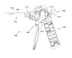
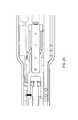
- FIG. 1is a perspective view from a side of an exemplary embodiment of an electric stapler according to the invention
- FIG. 2is a fragmentary side elevational view of the stapler of FIG. 1 with a right half of a handle body and with a proximal backbone plate removed;
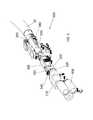
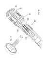
- FIG. 3is an exploded, perspective view of an anvil control assembly of the stapler of FIG. 1 ;
- FIG. 4is an enlarged, fragmentary, exploded, perspective view of the anvil control assembly of FIG. 3 ;
- FIG. 5is a fragmentary, perspective view of a staple firing control assembly of the stapler of FIG. 1 from a rear side thereof;
- FIG. 6is an exploded, perspective view of the staple firing control assembly of the stapler of FIG. 1 ;
- FIG. 7is an enlarged, fragmentary, exploded, perspective view of the staple firing control assembly of FIG. 6 ;
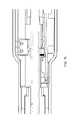
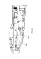
- FIG. 8is a fragmentary, horizontally cross-sectional view of the anvil control assembly from below the handle body portion of the stapler of FIG. 1 ;
- FIG. 9is a fragmentary, enlarged, horizontally cross-sectional view from below a proximal portion of the anvil control assembly FIG. 8 ;
- FIG. 10is a fragmentary, enlarged, horizontally cross-sectional view from below an intermediate portion of the anvil control assembly of FIG. 8 ;
- FIG. 11is a fragmentary, enlarged, horizontally cross-sectional view from below a distal portion of the anvil control assembly of FIG. 8 ;
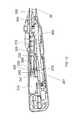
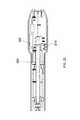
- FIG. 12is a fragmentary, vertically cross-sectional view from a right side of a handle body portion of the stapler of FIG. 1 ;
- FIG. 13is a fragmentary, enlarged, vertically cross-sectional view from the right side of a proximal handle body portion of the stapler of FIG. 12 ;
- FIG. 14is a fragmentary, enlarged, vertically cross-sectional view from the right side of an intermediate handle body portion of the stapler of FIG. 12 ;
- FIG. 15is a fragmentary, further enlarged, vertically cross-sectional view from the right side of the intermediate handle body portion of the stapler of FIG. 14 ;
- FIG. 16is a fragmentary, enlarged, vertically cross-sectional view from the right side of a distal handle body portion of the stapler of FIG. 12 ;
- FIG. 17is a perspective view of a portion of an anvil of the stapler of FIG. 1 ;
- FIG. 18is a fragmentary, cross-sectional view of a removable stapling assembly including the anvil, a stapler cartridge, a force switch, and a removable cartridge connecting assembly of the stapler of FIG. 1 ;
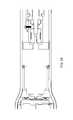
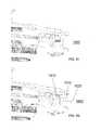
- FIG. 19is a fragmentary, horizontally cross-sectional view of the anvil control assembly from above the handle body portion of the stapler of FIG. 1 with the anvil rod in a fully extended position;
- FIG. 20is a fragmentary, side elevational view of the handle body portion of the stapler of FIG. 1 from a left side of the handle body portion with the left handle body and the circuit board removed and with the anvil rod in a fully extended position;
- FIG. 21is a fragmentary, side elevational view of the handle body portion of the stapler of FIG. 20 with the anvil rod in a 1-cm anvil closure position;
- FIG. 22is a fragmentary, horizontally cross-sectional view of the anvil control assembly from above the handle body portion of the stapler of FIG. 1 with the anvil rod in a safe staple firing position;
- FIG. 23is a fragmentary, horizontally cross-sectional view of the anvil control assembly from above the handle body portion of the stapler of FIG. 1 with the anvil rod in a fully retracted position;
- FIG. 24is a fragmentary, horizontally cross-sectional view of the firing control assembly from above the handle body portion of the stapler of FIG. 1 ;
- FIG. 25is a fragmentary, enlarged, horizontally cross-sectional view from above a proximal portion of the firing control assembly of FIG. 24 ;
- FIG. 26is a fragmentary, enlarged, horizontally cross-sectional view from above an intermediate portion of the firing control assembly of FIG. 24 ;
- FIG. 27is a fragmentary, enlarged, horizontally cross-sectional view from above a distal portion of the firing control assembly of FIG. 24 ;
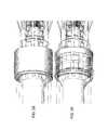
- FIGS. 28 and 29are shaded, fragmentary, enlarged, partially transparent perspective views of a staple cartridge removal assembly of the stapler of FIG. 1 ;
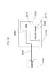
- FIG. 30is a schematic circuit diagram of an exemplary encryption circuit for interchangeable parts of the medical device according to the invention.
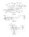
- FIG. 31is a bar graph illustrating a speed that a pinion moves a rack shown in FIG. 32 for various loads;
- FIG. 32is a fragmentary, perspective view of a simplified, exemplary portion of a gear train according to the present invention between a gear box and a rack;
- FIG. 33is a fragmentary, vertically longitudinal, cross-sectional view of a distal end of an articulating portion of an exemplary embodiment of an end effector with the inner tube, the pushrod-blade support, the anvil, the closure ring, and the near half of the staple sled removed;
- FIG. 34is a schematic circuit diagram of an exemplary switching assembly for a power supply according to the invention.
- FIG. 35is a schematic circuit diagram of an exemplary switching assembly for forward and reverse control of a motor according to the invention.
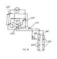
- FIG. 36is a schematic circuit diagram of another exemplary switching assembly for the power supply and the forward and reverse control of the motor according to the invention.
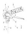
- FIG. 37is a left side elevational view of the device according to the invention with the outer shell removed;
- FIG. 38is an enlarged left side elevational view of a portion the device of FIG. 37 with the left side frame removed;
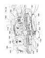
- FIG. 39is a right side elevational view of the device of FIG. 37 ;
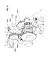
- FIG. 40is an enlarged right side elevational view of a portion the device of FIG. 38 with the right side frame removed;
- FIG. 41is a perspective view of the device portion of FIG. 40 from the right rear;
- FIG. 42is a rear elevational view of the device portion of FIG. 40 ;
- FIG. 43is a perspective view of the device portion of FIG. 40 from the left rear with the first to third stage cover removed;
- FIG. 44is a perspective view of the device portion of FIG. 40 from above the right side with the power supply removed;
- FIG. 45is a perspective view of the device portion of FIG. 44 with the manual release lever in a first intermediate position with the castle gear in the separated position;
- FIG. 46is a perspective view of the device portion of FIG. 45 with the manual release lever in a second intermediate position
- FIG. 47is a top plan view of the device portion of FIG. 46 with the manual release lever in a third intermediate position;
- FIG. 48is an enlarged perspective view of the manual release assembly from the right side with the second stage release gear, two cam plates, and a pawl spring removed with the pawl in an upper, unratcheting position;
- FIG. 49is a perspective view of the manual release lever from below a right front side
- FIG. 50is a perspective view of the manual release lever from below a right rear side
- FIG. 51is a perspective view of the manual release lever from below a left rear side
- FIG. 52is a perspective view of a cam plate from a left side
- FIG. 53is a perspective view of a castle gear from a right side
- FIG. 54is a perspective view of a fourth stage pinion from the left side
- FIG. 55is a perspective view of the device portion of FIG. 44 from above a front right side with a pawl against a pawl cam;
- FIG. 56is a perspective view of the device portion of FIG. 55 with the pawl off of the pawl cam and against a ratchet gear and with the castle gear in the separated position;
- FIG. 57is a perspective view of the device portion of FIG. 44 from above a front left side with the manual release in an intermediate position;
- FIG. 58is a perspective view of the device portion of FIG. 57 with the manual release in another intermediate position;
- FIG. 59is an enlarged right side elevational view of a portion of the device of FIG. 40 with the end effector control handle in an unactuated position;
- FIG. 60is an enlarged right side elevational view of a the device portion of FIG. 59 with the end effector control handle in a partially actuated position;
- FIG. 61is an enlarged perspective view of a shaft connector portion of the device of FIG. 37 from above the front right side with a removable end effector shaft secured in a frame;
- FIG. 62is an enlarged perspective view of the shaft connector portion of FIG. 61 with shaft securing device removed to permit removal of the end effector shaft from the frame;
- FIG. 63is an elevational view of the interior of a left half of the outer shell of the device of FIG. 37 ;
- FIG. 64is an elevational view of the interior of a right half of the outer shell of the device of FIG. 37 ;
- FIG. 65is an elevational view of the exterior of the right half of the outer shell of the device of FIG. 37 ;
- FIG. 66is an elevational view of the exterior of the left half of the outer shell of the device of FIG. 37 .
- FIGS. 1 to 2there is shown an exemplary embodiment of an electric surgical circular stapler 1 .
- the present applicationapplies the electrically powered handle to a circular surgical staple head for ease of understanding only.
- the inventionis not limited to circular staplers and can be applied to any surgical stapling head, such as a linear stapling device, for example.
- Such an exemplary embodimentis described, in particular, starting with FIG. 37 .
- the powered stapler 1has a handle body 10 containing three switches: an anvil open switch 20 , an anvil close switch 21 , and a staple firing switch 22 . Each of these switches is electrically connected to a circuit board 500 (see FIG. 12 ) having circuitry programmed to carry out the stapling functions of the stapler 1 .
- the circuit board 500is electrically connected to a power supply 600 contained within the handle body 10 .
- One exemplary embodimentutilizes 2 to 6 Lithium CR123 or CR2 cells as the power supply 600 .
- Other power supply embodimentsare possible, such as rechargeable batteries or a power converter that is connected to an electric mains (in the latter embodiment, the stapler would not be self-powered or self-contained).
- the terms self-powered or self-contained when used with regard to the electric power supply ( 600 )are interchangeable and mean that the power supply is a complete and independent unit in and of itself and can operate under its own power without the use of external power sources.
- a power supply having an electric cord that is plugged into an electric mains during useis not self-powered or self-contained.
- Insulated conductive wires or conductor tracks on the circuit board 500connect all of the electronic parts of the stapler 1 , such as an on/off switch 12 , a tissue compression indicator 14 , the anvil and firing switches 20 , 21 , 22 , the circuit board 500 , and the power supply 600 , for example. But these wires and conductors are not shown in the figures of the drawings for ease of understanding and clarity.
- the distal end of the handle body 10is connected to a proximal end of a rigid anvil neck 30 .
- a coupling device 40for removably attaching a staple cartridge 50 and an anvil 60 thereto.
- the staple cartridge 50can be non-removable in a single-use configuration of the stapler 1 .
- FIG. 2shows the handle body 10 with the right half 13 of the handle body 10 and the circuit board 500 removed.
- a proximal backbone plate 70is also removed from the view of FIG. 2 to allow viewing of the internal components inside the handle body 10 from the right side thereof.
- a first of these axesis the staple control axis 80 , which is relatively horizontal in the view of FIG. 2 .
- the staple control axis 80is the centerline on which lie the components for controlling staple actuation.
- the second of these axesis the anvil control axis 90 and is disposed at an angle to the staple control axis 80 .
- the anvil control axis 90is the centerline on which lie the components for controlling anvil actuation. It is this separation of axes 80 , 90 that allows the electric stapler 1 to be powered using a handle body 10 that is small enough to fit in a physician's hand and that does not take up so much space that the physician becomes restricted from movement in all necessary directions and orientations.
- the on/off switch 12e.g., a grenade pin
- powere.g., battery power
- the tissue compression indicator 14indicates to the physician that the tissue being compressed between the anvil 60 and the staple cartridge 50 has or has not been compressed with greater than a pre-set compressive force, which will be described in further detail below.
- This indicator 14is associated with a force switch 400 that has been described in co-pending U.S. Patent Provisional Application Ser. No. 60/801,989 filed May 19, 2006, and titled “Force Switch” (the entirety of which is incorporated by reference herein).
- An anvil control frame 110is aligned along the anvil control axis 90 to house and/or fix various part of the anvil control assembly 100 thereto.
- the anvil control frame 110has a proximal mount 112 , an intermediate mount 114 , and a distal mount 116 .
- Each of these mounts 112 , 114 , 116can be attached to or integral with the control frame 110 .
- the proximal mount 112has two halves and is separate from the frame 110 and the intermediate mount 114 is separate from the frame 110 .
- the anvil motor 120includes the drive motor and any gearbox that would be needed to convert the native motor revolution speed to a desired output axle revolution speed.
- the drive motorhas a native speed of approximately 10,000 rpm and the gearbox converts the speed down to between approximately 50 and 70 rpm at an axle 122 extending out from a distal end of the anvil motor 120 .
- the anvil motor 120is secured both longitudinally and rotationally inside the proximal mount 112 .
- a motor-shaft coupler 130is rotationally fixed to the axle 122 so that rotation of the axle 122 translates into a corresponding rotation of the motor coupler 130 .
- the nut assembly 140is, in this embodiment, a two part device having a proximal nut half 141 and a distal nut half 142 rotationally and longitudinally fixed to the proximal nut half 141 . It is noted that these nut halves 141 , 142 can be integral if desired. Here, they are illustrated in two halves for ease of manufacturing.
- the proximal end of the nut assembly 140is rotationally fixed to the distal end of the coupler 130 . Longitudinal and rotational support throughout the length of these two connected parts is assisted by the intermediate 114 and distal 116 mounts.
- a proximal nut bushing 150(see FIG. 3 ) is interposed between the intermediate mount 114 and the proximal nut half 141 and a distal nut bushing 160 is interposed between the distal mount 116 and the distal nut half 142 to have these parts spin efficiently and substantially without friction within the handle body 10 and the anvil control frame 110 .
- the bushings 150 , 160can be of any suitable bearing material, for example, they can be of metal such as bronze or a polymer such as nylon.
- a thrust washer 170is disposed between the proximal bushing 150 and the proximal nut half 141 .
- Rotation of the coupler 130 and nut assembly 140is used to advance or retract a threaded rod 180 , which is the mechanism through which the anvil 60 is extended or retracted.
- the threaded rod 180is shown in further detail in the exploded view of FIGS. 3 to 4 and is described in further detail below.
- a rod support 190is attached to a distal end of the anvil control frame 110 for extending the supporting surfaces inside the nut assembly 140 that keep the rod 180 aligned along the anvil control axis 90 .
- the rod support 190has a smooth interior shape corresponding to an external shape of the portion of the rod 180 that passes therethrough. This mating of shapes allows the rod 180 to move proximally and distally through the support 190 substantially without friction.
- a cylindrical rod bushing 192is disposed between the support 190 and the rod 180 .
- the rod bushing 192is not visible in FIG. 2 because it rests inside the support 190 .
- the rod bushing 192is visible in the exploded view of FIGS. 3 to 4 .
- the internal shape of the support 190corresponds to the external shape of the rod bushing 192 and the internal shape of the rod bushing 192 corresponds to the external shape of the portion of the rod 180 that passes therethrough.
- the rod bushing 192can be, for example, of metal such as bronze or a polymer such as nylon.
- the components along the staple control axis 80form the staple control assembly 200 .
- the staple control assembly 200is illustrated in FIG. 5 viewed from a proximal upper and side perspective.
- the proximal end of the staple control assembly 200includes a stapling motor 210 .
- the stapling motor 210includes the drive motor and any gearbox that would be needed to convert the native motor revolution speed to a desired revolution speed.
- the drive motorhas a native speed of approximately 20,000 rpm and the gearbox converts the speed to approximately 200 rpm at an output axle 212 at the distal end of the gearbox.
- the axle 212cannot be seen in the view of FIG. 5 but can be seen in the exploded view of FIGS. 6 to 7 .
- the stapling motor 210is rotationally and longitudinally fixed to a motor mount 220 .
- Distal of the motor mount 220is an intermediate coupling mount 230 .
- This coupling mount 230has a distal plate 232 that is shown, for example in FIG. 6 .
- the distal plate 232is removable from the coupling mount 230 so that a rotating screw 250 can be held therebetween. It is this rotating screw 250 that acts as the drive for ejecting the staples out of the staple cartridge 50 .
- the efficiency in transferring the rotational movement of axle 212 to the rotating screw 250is a factor that can substantially decrease the ability of the stapler 1 to deliver the necessary staple ejection longitudinal force of up to 250 pounds.
- an exemplary embodiment of the screw 250has an acme profile thread.
- the stapling motor 210can be housed “loosely” within a chamber defined by the handle body 10 so that it is rotationally stable but has play to move radially and so that it is longitudinally stable but has play to move. In such a configuration, the stapling motor 210 will “find its own center” to align the axis of the axle 212 to the axis of the screw 250 , which, in the exemplary embodiment, is also the staple control axis 80 .
- FIGS. 1 to 5A second exemplary embodiment for aligning the axle 212 and the screw 250 is illustrated in FIGS. 1 to 5 , for example.
- a proximal end of a flexible coupling 240is fixed (both rotationally and longitudinally) to the axle 212 .
- This connectionis formed by fitting the distal end of the axle 212 inside a proximal bore 241 of the flexible coupling 240 . See FIG. 12 .
- the axle 212is, then, secured therein with a proximal setscrew 213 .
- the screw 250has a proximal extension 251 that fits inside a distal bore 242 of the flexible coupling 240 and is secured therein by a distal setscrew 252 .
- the figures of the drawingsshow the flexible coupling 240 with ridges in the middle portion thereof.
- the partis of aluminum or molded plastic and has a spiral or helixed cut-out around the circumference of the center portion thereof.
- one end of the coupling 240can move in any radial direction (360 degrees) with respect to the other end (as in a gimbal), thus providing the desired flex to efficiently align the central axes of the axle 212 and the screw 250 .
- the proximal extension 251 of the screw 250is substantially smaller in diameter than the diameter of the bore 231 that exists in and through the intermediate coupling mount 230 .
- This bore 231has two increasing steps in diameter on the distal side thereof.
- the first increasing step in diameteris sized to fit a proximal radius screw bushing 260 , which is formed of a material that is softer than the intermediate coupling mount 230 .
- the proximal radius screw bushing 260only keeps the screw 250 axially aligned and does not absorb or transmit any of the longitudinal thrust.
- the second increasing step in diameteris sized to fit a proximal thrust bearing 270 for the screw 250 .
- proximal and distal platessandwich a bearing ball retainer plate and bearing balls therebetween.
- This thrust bearing 270absorbs all of the longitudinal thrust that is imparted towards the axle 212 while the up to 250 pounds of longitudinal force is being applied to eject the staples in the staple cartridge 50 .
- the proximal extension 251 of the screw 250has different sized diameters for each of the interiors of the screw bushing 260 and the thrust bearing 270 .
- the motor mount 220 and the coupling mount 230therefore, form the two devices that hold the flexible coupling 240 therebetween.
- the rotating screw 250is held inside the distal plate 232 with a distal radius screw bushing 280 similar to the proximal radius screw bushing 260 .
- the screw 250rotates freely within the distal plate 232 .
- the screw 250is threaded within a moving nut 290 . Movement of the nut 290 is limited to the amount of movement that is needed for complete actuation of the staples; in other words, the nut 290 only needs to move through a distance sufficient to form closed staples between the staple cartridge 50 and the anvil 60 and to extend the cutting blade, if any, within the staple cartridge 50 , and then retract the same.
- the staplesare at rest and ready to be fired.
- the staplesare stapled through and around the tissue interposed between the staple cartridge 50 and the anvil, and the knife, if any, is passed entirely through the tissue to be cut.
- the distal-most position of the nut 290is limited by the location of the distal plate 232 .
- the longitudinal length of the threads of the screw 250 and the location of the distal plate 232limit the distal movement of the nut 290 .
- Frictional losses between the screw 250 and the nut 290contribute to a significant reduction in the total pounds of force that can be transmitted to the staple cartridge 50 through the cartridge plunger 320 . Therefore, it is desirable to select the materials of the screw 250 and the nut 290 and the pitch of the threads of the screw 250 in an optimized way. It has been found that use of a low-friction polymer for manufacturing the nut 290 will decrease the friction enough to transmit the approximately 250 pounds of longitudinal force to the distal end of the cartridge plunger 320 —the amount of force that is needed to effectively deploy the staples.
- DELRIN® AF Blend Acetala thermoplastic material combining TEFLON® fibers uniformly dispersed in DELRIN® acetal resin
- RULON®a compounded form of TFE fluorocarbon
- a nut coupling bracket 300is longitudinally fixed to the nut 290 so that it moves along with the nut 290 .
- the nut coupling bracket 300provides support for the relatively soft, lubricious nut material.
- the bracket 300has an interior cavity having a shape corresponding to the exterior shape of the nut 290 .
- the nut 290fits snugly into the coupling bracket 300 and movement of the nut 290 translates into a corresponding movement of the nut coupling bracket 300 .
- the shape of the nut coupling bracket 300is, in the exemplary embodiment, dictated by the components surrounding it and by the longitudinal forces that it has to bear.
- the nut coupling bracket 300also has a distal housing 304 for receiving therein a stiffening rod 310 .
- the stiffening rod 310increases the longitudinal support and forms a portion of the connection between the nut 290 and a cartridge plunger 320 (see, i.e., FIG. 5 ), which is the last moving link between elements in the handle body 10 and the staple cartridge 50 .
- a firing bracket 330disposed between the distal end of the nut coupling bracket 300 and the stiffening rod 310 , strengthens the connection between the nut coupling bracket 300 and the rod 310 .
- This backboneis a frame providing multi-directional stability and is made up of four primary parts (in order from proximal to distal): the anvil control frame 110 , the proximal backbone plate 70 (shown in FIGS. 3 to 4 and 6 to 7 ), a distal backbone plate 340 , and the anvil neck 30 .
- Each of these four partsis longitudinally and rotationally fixed to one another in this order and forms the skeleton on which the remainder of the handle components is attached in some way.
- the handle body 10which in an exemplary embodiment is formed of two halves, a left half 11 and a right half 13 .
- supportcould be single frame, stamped, or incorporated into the handle halves 11 , 13 .
- anvil control assembly 100Functionality of the anvil control assembly 100 is described with regard to FIGS. 17 to 27 .
- the anvil open switch 20is depressed to extend the distal end of the trocar tip 410 housed within the staple cartridge and which is longitudinally fixedly connected to the screw 250 .
- the point of the trocar tip 410can, now, be passed through or punctured through tissue that is to be stapled.
- the usercan, at this point, replace the anvil 60 onto the trocar tip 410 from the opposite side of the tissue (see FIG. 18 ) and, thereby, lock the anvil 60 thereon.
- the anvil closed switch 22can be actuated to begin closing the anvil 60 against the staple cartridge 50 and pinch the tissue therebetween within an anvil-cartridge gap 62 .
- FIGS. 8 to 10, 14 to 15, and 18To describe how the trocar tip controlling movement of the anvil 60 occurs, reference is made to FIGS. 8 to 10, 14 to 15, and 18 .
- a rod-guiding pin 143is positioned within the central bore 144 of the distal nut half 142 .
- the pin 143catches the proximal end of the thread 182 to surround the pin 143 therein.
- rotation of the nut 140 with the pin 143 inside the thread 182will cause proximal or distal movement of the rod 180 , depending on the direction of nut rotation.
- the thread 182has a variable pitch, as shown in FIGS.
- the rod 180is provided with a shorter pitched thread portion 184 to engage in a corresponding internal thread 145 at the proximal end of the central bore 144 of the proximal nut half 141 .
- the shorter pitched thread portion 184engages the internal thread 145
- the entire transverse surface of the thread portion 184contacts the internal thread 145 .
- This surface contactis much larger than the contact between the pin 143 and any portion of the thread 182 and, therefore, can withstand all the longitudinal force that occurs with respect to anvil 60 closure, especially when the anvil 60 is closing about tissue during the staple firing state.
- the pin 143bears up to approximately 30 to 50 pounds of longitudinal force. This is compared to the threads, which can hold up to 400 pounds of longitudinal force—an almost 10-to-1 difference.
- An alternative exemplary embodiment of anvil control assembly 100can entirely remove the complex threading of the rod 180 .
- the rod 180has a single thread pitch and the anvil motor 120 is driven (through corresponding programming in the circuit board 500 ) at different speeds dependent upon the longitudinal position of the single-thread rod 180 .
- the control programmingcan take many forms.
- the microcontroller on the battery powered circuit board 500can apply pulse modulation (e.g., pulse-width, pulse-frequency) to drive either or both of the motors.
- pulse modulatione.g., pulse-width, pulse-frequency
- the stapler 1is a device that has a low duty cycle, or is a one-use device, components can be driven to exceed acceptable manufacturers' specifications.
- a gear boxcan be torqued beyond its specified rating.
- a drive motorfor example, a 6 volt motor, can be overpowered, for example, with 12 volts.
- the longer-pitched thread portion 183allows the user to quickly close the anvil 60 to the tissue in a tissue pre-compressing state. Thereafter, it is desirable to compress the tissue slowly so that the user has control to avoid over-compression of the tissue. As such, the shorter pitched thread portion 184 is used over this latter range of movement and provides the user with a greater degree of control.
- 60/801,989can be used to indicate to the user through the tissue compression indicator 14 (and/or to the control circuitry of the circuit board 500 ) that the tissue is being compressed with a force that is greater than the pre-load of the spring 420 inside the force switch 400 .
- FIG. 18illustrates the force switch 400 embodiment in the normally-open configuration described as the first exemplary embodiment of U.S. Patent Provisional Application Ser. No. 60/801,989.
- a strain gaugecan also be used for measuring tissue compression.
- FIGS. 19 to 23illustrate movement of the rod 180 from an anvil-extended position (see FIGS. 19 to 20 ), to a 1-cm-closure-distance position (see FIG. 21 ), to a staple-fire-ready position (see FIG. 22 ), and, finally, to an anvil fully closed position (see FIG. 23 ).
- Movement of the rod 180is controlled electrically (via the circuit board 500 ) by contact between a portion of a cam surface actuator 185 on the rod 180 and actuating levers or buttons of a series of micro-switches positioned in the handle body 10 .
- a rod-fully-extended switch 610(see FIG. 19 ) is positioned distal in the handle body 10 to have the actuator 185 compress the activation lever of the rod-fully-extended switch 610 when the rod 180 (and, thereby, the anvil 60 ) is in the fully extended position.
- a 1-cm switch 612is positioned in an intermediate position within the handle body 10 (see FIGS. 20 to 21 ) to prevent a 1-cm cam surface portion 186 of the rod 180 from pressing the activation button of the 1-cm switch 612 when the rod 180 (and, thereby, the anvil 60 ) is within 1 cm of the fully closed position. After passing the 1-cm closure distance, as shown in FIG.
- the cam surface actuator 185engages a staple-fire-ready switch 614 .
- the lower end of the actuator 185 as viewed in FIGS. 22 to 23has a bevel on both the forward and rear sides with respect to the button of the staple-fire-ready switch 614 and the distance between the portion on the two bevels that actuates the button (or, only the flat portion thereof) corresponds to the acceptable staple forming range (i.e., safe firing length) of the staples in the staple cartridge 50 .
- the acceptable staple forming rangei.e., safe firing length
- FIG. 23show the rod 180 in the proximal-most position, which is indicated by the top end of the actuator 185 closing the lever of a rod fully-retracted switch 616 .
- the programming in the circuit board 500prevents the motor 120 from turning in a rod-retraction direction; in other words, it is a stop switch for retracting the rod 180 in the proximal direction.
- FIGS. 2 to 3, 11 to 12, and 16illustrate the distal end of the rod 180 not being connected to another device at its distal end (which would then contact the proximal end of the force switch 400 ).
- the connection band or bands between the distal end of the rod 180 and the proximal end of the force switch 400are not shown in the drawings only for clarity purposes.
- the pull-bandsare flat and flexible to traverse the curved underside of the cartridge plunger 320 through the anvil neck 30 and up to the proximal end of the force switch 400 .
- the bandswould be connected to the proximal end of the trocar tip 410 that releasably connects to the proximal end of the anvil 60 .
- the stapling motor 210is held between a motor bearing 222 and a motor shaft cover 224 .
- the axle 212 of the stapling motor 210is rotationally connected to the proximal end of the flexible coupling 240 and the distal end of the flexible coupling 240 is rotationally connected to the proximal end of the screw 250 , which rotates on bearings 260 , 270 , 280 that are disposed within the intermediate coupling mount 230 and the distal plate 232 .
- the longitudinally translating nut 290is threaded onto the screw 250 between the coupling mount 230 and the distal plate 232 . Therefore, rotation of the axle 212 translates into a corresponding rotation of the screw 250 .
- the nut coupling bracket 300is longitudinally fixed to the nut 290 and to the stiffening rod 310 and the firing bracket 330 .
- the firing bracket 330is longitudinally fixed to the cartridge plunger 320 , which extends (through a non-illustrated staple driver) up to the staple cartridge 50 (or to the staples). With such a connection, longitudinal movement of the nut 290 translates into a corresponding longitudinal movement of the cartridge plunger 320 . Accordingly, when the staple firing switch 22 is activated, the stapling motor 210 is caused to rotate a sufficient number of times so that the staples are completely fired from the staple cartridge 50 (and the cutting blade, if present, is extended to completely cut the tissue between the anvil 60 and the staple cartridge 50 ). Programming in the circuitry, as described below, then causes the cartridge plunger 320 to retract after firing and remove any portion of the staple firing parts and/or the blade within the staple cartridge 50 from the anvil-cartridge gap 62 .
- Control of this stapling movementoccurs through micro-switches connected to the circuit board 500 through electrical connections, such as wires.
- a first of these control switches, the proximal staple switch 618controls retraction of the staple control assembly 200 and defines the proximal-most position of this assembly 200 .
- an actuation plate 306is attached, in an adjustable manner, to a side of the nut coupling bracket 300 . See, e.g., FIGS. 6 and 24 .
- a second of the switches for controlling movement of the staple control assembly 200is located opposite a distal transverse surface of the stiffening rod 310 . See, e.g. FIG. 27 . At this surface is disposed a longitudinally adjustable cam member 312 that contacts a distal staple switch 620 .
- the cam member 312is a screw that is threaded into a distal bore of the stiffening rod 310 . Accordingly, when the nut 290 moves distally to cause the cam member 312 of the stiffening rod 310 to activate the distal staple switch 620 , power to the stapling motor 210 is removed to stop further distally directed movement of the staple control assembly 200 .
- FIGS. 28 and 29illustrate a removable connection assembly to permit replacement of a different staple cartridge 60 on the distal end of the anvil 30 .
- the proximal-most chamber of the handle body 10defines a cavity for holding therein a power supply 600 .
- This power supply 600is connected through the circuit board 500 to the motors 120 , 210 and to the other electrical components of the stapler 1 .
- the electric stapler 1includes, as set forth above in an exemplary embodiment, two drive motors 120 , 210 powered by batteries and controlled through pushbuttons 20 , 21 , 22 .
- the ranges of travel of each motor 120 , 210are controlled by limit switches 610 , 616 , 618 , 620 at the ends of travel and at intermediary locations 612 , 614 along the travel.
- the logic by which the motors 120 , 210 are controlledcan be accomplished in several ways.
- relayor ladder logic
- relaycan be used to define the control algorithm for the motors 120 , 210 and switches 610 , 612 , 614 , 616 , 618 , 620 .
- Such a configurationis a simple but limited control method.
- a more flexible methodemploys a microprocessor-based control system that senses switch inputs, locks switches out, activates indicator lights, records data, provides audible feedback, drives a visual display, queries identification devices (e.g., radio frequency identification devices (RFIDs) or cryptographic identification devices), senses forces, communicates with external devices, monitors battery life, etc.
- RFIDsradio frequency identification devices
- the microprocessorcan be part of an integrated circuit constructed specifically for the purpose of interfacing with and controlling complex electro-mechanical systems. Examples of such chips include those offered by Atmel, such as the Mega 128, and by PIC, such as the PIC 16F684.
- a software programis required to provide control instructions to such a processor. Once fully developed, the program can be written to the processor and stored indefinitely. Such a system makes changes to the control algorithm relatively simple; changes to the software that are uploaded to the processor adjust the control and user interface without changing the wiring or mechanical layout of the device.
- a power-on eventis a one time occurrence.
- the power-oncan be accomplished by pulling a tab or a release that is permanently removed from the device. The removal enables battery contact, thus powering on the device.
- the control programwhen the device is powered on, the control program begins to execute and, prior to enabling the device for use, goes through a routine that ensures awareness of actual positions of the extend/retract and firing sub-assemblies, referred to as a homing routine.
- the homing routinemay be executed at the manufacturer prior to shipping to the user. In such a case, the homing routine is performed, the positions of the assemblies are set, and the device is shipped to the user in a ready-to-use condition. Upon power-up, the device verifies its positions and is ready to use.
- Visual indicatorse.g., LEDs
- the pushbutton switches 20 , 21 , 22they can be lit (or backlit) when active and unlit when not active.
- the indicatorscan blink to convey additional information to the user.
- a given lightcan blink at an ever-increasing rate as the response becomes imminent, for example.
- the indicatorscan also light with different colors to indicate various states.
- Camsare used in various locations at the stapler 1 to activate limit switches that provide position information to the processor. By using linear cams of various lengths, position ranges can be set. Alternatively, encoders can be used instead of limit switches (absolute and incremental positioning). Limit switches are binary: off or on. Instead of binary input for position information, encoders (such as optical encoders) can be used to provide position information. Another way to provide position feedback includes mounting pulse generators on the end of the motors that drive the sub-assemblies. By counting pulses, and by knowing the ratio of motor turns to linear travel, absolute position can be derived.
- processorscreates the ability to store data. For example, vital, pre-loaded information, such as the device serial number and software revision can be stored. Memory can also be used to record data while the stapler 1 is in use. Every button press, every limit switch transition, every aborted fire, every completed fire, etc., can be stored for later retrieval and diagnosis. Data can be retrieved through a programming port or wirelessly.
- the devicecan be put into diagnostic mode through a series of button presses. In this diagnostic mode, a technician can query the stapler 1 for certain data or to transmit/output certain data.
- Response from the stapler 1 to such a querycan be in the form of blinking LEDs, or, in the case of a device with a display, visual character data, or can be electronic data.
- a strain gaugecan be used for analog output and to provide an acceptable strain band.
- addition of a second spring and support componentscan set this band mechanically.
- An exemplary control algorithm for a single fire stapler 1can include the following steps:
- the stapleris a one-way device.
- the test userneeds to have the ability to move the trocar 410 and anvil 60 back and forth as desired.
- the power-on featurepermits entry by the user into a manual mode for testing purposes. This test mode can be disengaged and the stapler reset to the use mode for packaging and shipment.
- a homing sequencecan be programmed to place the anvil 60 one centimeter (for example) away from the staple cartridge 50 before powering down for packaging and shipment.
- the userturns the stapler on (switch 12 ). Staples should not be allowed to fire at any time prior to being in a proper staple-firing position and a desired tissue compression state.
- the anvil/trocar extend/retract functionis the only function that is enabled. In this state, the extend and retract buttons 20 , 21 are lit and the staple firing switch 22 is not lit (i.e., disabled).
- the trocar 410Before use inside the patient, the trocar 410 is extended and the anvil 60 is removed. If the stapler is being used to anastomose a colon, for example, the trocar 410 is retracted back into the anvil neck 30 and the staple cartridge 50 and anvil neck 30 are inserted trans-anally into the colon to a downstream side of the dissection.
- the anvil 60in contrast, is inserted through an upstream laparoscopic incision and placed at the upstream side of the dissection.
- the anvil 60is attached to the trocar 410 and the two parts are retracted towards the staple cartridge 50 until a staple ready condition occurs. As set forth above, the anvil is moved to a distance that does not substantially compress and, specifically, does not desiccate, the tissue therebetween. At this point, staple firing can occur when desired.
- the staple firing sequenceis started by activating the staple fire switch 22 . Staple firing can be aborted anytime during the firing sequence, whether prior to movement (during the blanching cycle) or during movement (whether the staples have started to form or not).
- the softwareis programmed to begin a staple firing countdown sequence because it is understood that the tissue needs to be compressed and allowed to desiccate before staple firing should occur.
- the anvil 60closes upon the interposed tissue and begins to compress the tissue.
- the staple firing sequenceincludes an optimal tissue compression (OTC) measurement and a feedback control mechanism that causes staples to be fired only when the compression is in a desired pressure range, referred to as the OTC range, and a sufficient time period has elapsed to allow fluid removal from the compressed tissue.
- OTC rangeis known beforehand based upon known characteristics of the tissue that is to be compressed between the anvil 60 and the staple cartridge 50 (the force switch can be tuned for different tissue OTC ranges). It is the force switch 400 that provides the OTC measurement and supplies the microprocessor with information indicating that the OTC for that particular tissue has been reached.
- the OTC statecan be indicated to the user with an LED, for example.
- the staple fire switch 22can be made to blink at a given rate and then proceed to blink faster and faster, for example, until firing occurs. If no abort is triggered during this wait time, the OTC state will remain for the preprogrammed desiccation duration and staple filing will occur after the countdown concludes.
- stapling of the dissectionoccurs simultaneously with a cutting of tissue at the center of the dissection. This cutting guarantees a clear opening in the middle of the circular ring of staples sufficient to create an opening for normal colon behavior after the surgery is concluded.
- the programincludes closed-loop anvil-compression control that is dependent upon continuous measurements provided by the force switch 400 . With this feedback, the compressed tissue is kept within the OTC range throughout the procedure and even after being desiccated.
- any actuation of a control switch by the usercan be programmed to abort the staple fire routine. If an abort occurs before the staple firing motor 210 is activated, the firing cycle stops, the anvil 60 is extended to a home position, and the staple fire switch 22 remains active and ready for a re-fire attempt, if desired. Alternatively, if the abort occurs during movement of the staple firing motor 210 , the firing cycle stops and the staple firing motor 210 is caused to extend the anvil 60 to its home position. At this point, the staple firing switch 22 is rendered inactive. Accordingly, the stapler (or that particular staple cartridge) can no longer be used (unless the staple cartridge is replaced).
- a staple range limit switchis queried for relative position of the staple cartridge 50 and anvil 60 . If the staple range limit switch is activated—meaning that anvil 60 is within an acceptable staple firing range—then the staple firing motor 210 can be made active and the firing cycle can be allowed to proceed. If the staple range limit switch is not activated, then the firing cycle is aborted, the anvil 60 is returned to the home position, and the staple firing switch 22 remains active and ready for a re-fire attempt.
- Poweringalso referred to as actuating, powering, controlling, or activating of the motor and/or the drive train of any portion of the end effector (e.g., anvil or stapler/cutter) is described herein. It is to be understood that such powering need not be limited to a single press of an actuation button by the user nor is the powering of a motor limited to a single energizing of the motor by the power supply. Control of any motor in the device can require the user to press an actuation button a number of times, for example, a first time to actuate a portion of the end effector for a first third of movement, a second time for a second third of movement, and a third time for a last third of movement.
- a first exemplary actuationcan move the staple sled or blade past the lock-out
- a second exemplary actuationcan move the part up to the tissue
- a third exemplary actuationcan move the sled past all staples to the end of the staple cartridge.
- powering of a motorneed not be constant, for example, where the motor is energized constantly from the time that the blade begins movement until it reaches the end point of its movement. Instead, the motor can be operated in a pulsed mode, a first example of which includes periodically switching on and off the power supplied by the power supply to the motor during actuation of an end effector function.
- the motorcan be pulsed ten times/second as the staple/cutter moves from its proximal/start position to its distal-most position.
- This pulsingcan be directly controlled or controlled by microprocessor, either of which can have an adjustable pulse rate.
- the motorcan be operated with a pulse modulation (pulse-width or pulse-frequency), with pulses occurring at very short time periods (e.g., tenths, hundredths, thousandths, or millionths of a second). Accordingly, when the power supply, the motor, and/or the drive train are described herein as being powered, any of these and other possible modes of operation are envisioned and included.
- the anvil 60After a completed staple firing, the anvil 60 remains in the closed position and only the extend switch 20 remains active (all other switches are deactivated). Once the anvil 60 is extended to at least the home position, both the extend and retract switches 20 , 21 are made active but the retraction switch 21 does not permit closure of the anvil 60 past the home position.
- the staple fire switch 22remains inactive after a completed staple firing.
- the anvil neck 30houses a linear force switch 400 connected to the trocar 410 .
- This switch 400is calibrated to activate when a given tensile load is applied.
- the given loadis set to correspond to a desired pressure that is to be applied to the particular tissue before stapling can occur. Interfacing this switch 400 with the processor can ensure that the firing of staples only occurs within the OTC range.
- identification deviceswith removable and/or interchangeable portions of the end effector.
- Such identification devicescan be used to track usage and inventory.
- One exemplary identification deviceemploys radio-frequency and is referred to as an RFID.
- an RFIDcan be placed in the staple cartridge to ensure compatibility with the particular stapler and an RFID reader for sensing compatible staple cartridges can be associated with the handle.
- the readerinterrogates the RFID mounted in the cartridge.
- the RFIDresponds with a unique code that the stapler verifies. If the stapler cartridge is labeled as verified, the stapler becomes active and ready for use. If the cartridge is rejected, however, the stapler gives a rejected indication (e.g., a blinking LED, an audible cue, a visual indicator).
- the antenna of the RFID readercan be constructed to only read the RFID when the staple cartridge is installed in the stapler or is very nearby (optimally, at the distal end of the device).
- Use of the RFIDcan be combined with a mechanical lockout to ensure that only one fire cycle is allowed per staple cartridge.
- RFIDshave drawbacks because the readers are expensive, the antennas are required to be relatively large, and the distance for reading is relatively close, typically measured in centimeters.
- Another exemplary identification deviceemploys encryption.
- encryptioncomes the need for processing numbers and, associated with such calculations, is use of processing chips (e.g., a microprocessor), one of which is to be placed on the interchangeable part, such as a staple cartridge or a replaceable end effector shaft.
- processing chipse.g., a microprocessor
- Such encryption chipshave certain characteristics that can be analyzed for optimization with the surgical instrument of the present invention.
- a separate power source for the interchangeable partis not desired. Not only would such a power source add cost, it would also add undesirable weight and take up space that is needed for other features or is just not available.
- power supply to the partshould come from the already existing power supply within the handle. Also, supply of power should be insured at all times. Because the interchangeable part is relatively small, the encryption chip should be correspondingly small.
- both the handle and the interchangeable partare configured to be disposable, therefore, both encryption processors should have a cost that allows disposability. Finally, connections between the encryption device on the interchangeable part and the corresponding encryption device on the handle should be minimized. As will be discussed below, the encryption device according to the present invention provides all of these desirable characteristics and limits the undesirable ones.
- DS2432 chipDevices for encrypted identification are commercially available.
- One of such encryption devicesis produced by Dallas Semiconductor and is referred to as the DS2432 chip.
- the DS2432 chipnot only provides encrypted identification between a reader and a transponder, but it also has a memory that can be used to store device-specific information, which information and its uses will be described in further detail below.
- One beneficial characteristic of the DS2432is that it is a 1-wire device. This means that the power and both of the input and output signals travel on the same line. With a 1-wire device such as the DS2432, there is only the need for a single wire to traverse the distance from the handle body 10 through the anvil neck 30 to the interchangeable staple cartridge 50 in order to make a connection between the handle and the end effector.
- One exemplary encryption circuit configurationplaces a first encryption chip on the interchangeable part (e.g., the staple cartridge).
- Ground for the first encryption chipis electrically connected to a metallic portion of the interchangeable part which, in turn, is electrically connected to ground of the device, for example, to the neck 30 .
- the 1-wire connection of the DS2432 chipis electrically connected to a contact pad that is somewhere on the interchangeable part but is electrically disconnected from ground.
- the interchangeable partis a linear 60 mm staple cartridge
- the DS2432can be attached to or embedded within the electrically insulated distal end of the cartridge distal of the last staple set.
- the encryption chipcan be embedded on a side of the cartridge opposite the staple ejection face so that it is neither exposed to the working surfaces nor to the exposed tissue when in use.
- the ground lead of the DS2432 chipcan be electrically connected to the metallic outer frame of the staple cartridge, which is electrically connected to ground of the stapler.
- the 1-wire leadis electrically connected to a first conductive device (such as a pad, a lead, or a boss) that is electrically insulated from the metallic frame of the cartridge.
- a single electrically conductive but insulated wireis connected at the proximal end to the circuit board or to the appropriate control electronics within the handle of the device.
- This wireis insulated from electrical contact with any other part of the stapler, especially the grounded frame, and travels from the handle, through the neck and up to the receiving chamber for the interchangeable part.
- the insulated wireis exposed and electrically connected to a second conductive device (such as a pad, a lead, or a boss) that is shaped to positively contact the first conductive device on the cartridge when the cartridge is locked into place in the end effector.
- the two conductive devicesform a direct electrical connection every time that the interchangeable part (e.g., the staple cartridge) is inserted within the end effector; in one particular embodiment, contact can be made only when the part is correctly inserted.
- the DS2432is also only a few square millimeters in area, making the chip easy to install on a small interchangeable part, such as a staple cartridge, while simultaneously satisfying the minimal size requirement. It is noted that the DS2432 chip is relatively inexpensive. To keep all communication with the DS2432 chip hidden from outside examination, a DS2460 (also manufactured by Dallas Semiconductor) can be used to perform a comparison of an encrypted transmission received from a DS2432 with an expected result calculated internally. The characteristics of both of these chips are explained, for example, by Dallas Semiconductors' Application Note 3675, which is hereby incorporated by reference herein in its entirety. The DS2460 chip costs significantly more than the DS2432 chip, but is still inexpensive enough to be disposed along with the handle.
- the number of disposable interchangeable parts of medical devicestypically outnumber the handle that receives the interchangeable parts by a significant amount. Accordingly, if the DS2432 chip is placed in the interchangeable part and the DS2460 chip is placed in the handle, the low cost encryption characteristic is satisfied.
- FIG. 2 of Application Note 3675There exists an alternative circuit configuration using two DS2432 chips that is explained in FIG. 2 of Application Note 3675, which circuit eliminates the need of the more expensive DS2460 chip by performing the comparison with a local microprocessor (e.g., microprocessor 2000 ). In such a configuration, the cost for adding encryption into the device 1 is reduced, however, as explained, the configuration gives up some aspects of security by making available to inspection both numbers that are to be compared.
- the process for electronically verifying the identity of an interchangeable part on a medical device using encryptionis described with an exemplary embodiment having one DS2432 chip and one DS2460 chip.
- the exemplary control circuit for the encryption deviceis shown in FIG. 30 .
- This exemplary embodimentis described using a linear stapler having a handle containing therein a circuit board with a microprocessor 2000 .
- One free I/O pin 2010 of the microprocessor 2000is connected to a first lead 2110 of the DS2460 and another I/O pin 2020 is connected to a second lead 2120 .
- Each interchangeable part 2200is provided with a DS2432 chip and the 1-wire lead is connected to a third I/O pin 2030 of the microprocessor 2000 .
- an interchangeable part 2200is connected to the device, making electrical contact with ground and with the 1-wire lead.
- the microprocessor 2000detects that a new part 2200 has been connected to the device 1 , it runs an authentication routine.
- the microprocessor 2000initiates a random number request to the DS2460 over the first communication pin 2010 .
- the DS2460has a pre-programmed secret number that is the same as the pre-programmed secret numbers stored in each of the DS2432 chips contained on the interchangeable parts 2200 . Therefore, when the same random number is provided to both the DS2432 and the DS2460 chips, the output result from each of the two chips will be identical.
- the DS2460generates a random number and supplies it, via the second pin 2020 , to the microprocessor 2000 for forwarding, via pin 2030 , on to the DS2432 over the 1-wire lead.
- the DS2432receives the random number, it applies its SHA-1 algorithm (developed by the National Institute of Standards and Technology (NIST)) to cryptographically generate a hash code reply.
- This hash code replyis transmitted back over the 1-wire lead to the microprocessor 2000 and is forwarded, via either pin 2010 or 2020 to the DS2460.
- the DS2460is also calculating its own a hash code reply.
- the DS2460internally applies the same random number sent to the DS2432 to its own SHA-1 algorithm and stores, internally, the generated hash code reply.
- the DS2460also stores the hash code reply transmitted from the DS2432 through the microprocessor 2000 . Both of the hash code replies are compared and, if they are identical, the interchangeable part 2200 is confirmed as authenticated. If there is a difference between the hash code replies, then the part 2200 is rejected and the device is placed in a state where the part 2200 either cannot be used or can be used, but only after certain safeguards are met. For example, data regarding the time, date, environment, etc.
- the unauthenticated partcan be stored for later or simultaneous transmission to the manufacturer (or its agent) to inform the manufacturer that the user is attempting to use or has used an unauthorized part 2200 with the device. If there was no encryption in the messages, the authentication messages could be intercepted and counterfeit, pirated, or unauthorized parts 2200 could be used without having to purchase the parts 2200 from an authorized distributor.
- the only information that is transmitted across lines that can be examinedis a single random number and a single hash code reply. It is understood that it would take hundreds of years to decrypt this SHA-1-generated reply, thus reducing any incentive for reverse engineering.
- the chips used in this exampleeach have secure memories that can only be accessed after authentication occurs, they can be programmed to employ multiple secret keys each stored within the memory. For example, if the DS2460 has multiple keys stored therein and the parts 2200 each have only one key selected from this stored set of multiple keys, the DS2460 can act as a “master” key to the “general” single keys of the parts 2200 .
- the instrument manufacturercan prevent a user from using unauthorized parts, thereby insuring use of only authorized parts. Not only does this guarantee that the manufacturer can receive royalties from sales of the interchangeable part, but it also allows the manufacture to insure that the quality of the surgical parts remains high.
- Having the encryption circuitry contain memorydramatically enhances the benefits provided by the present invention. For example, if a single end effector of a linear stapler can receive 30 mm, 60 mm, and 120 mm staple cartridges, for example, each size of the cartridges could be provided with an individualized key and the handle can be programmed to store and use each of these three keys.
- the handleUpon receiving a hash code reply that corresponds to one, but not the other two internally calculated hash code replies, the handle would know what kind of cartridge has been inserted in the device. Each cartridge could also contain in its memory cartridge-specific parameters, such as staple sled movement length, that are different among the various sized cartridges and, therefore, cause the handle to behave differently dependent upon the cartridge detected. The parameters examined can also account for revision levels in the particular part. For example, a revision 1 cartridge could have certain parameters for use and, by detecting that particular cartridge, programming could cause the handle to not allow use of revision 1 cartridges but allow use of revision 2 cartridges, or vice-versa.
- the cartridgecan store the identity of each handle to which it was connected, the identity of the handle that fired the cartridge, the time, date and other temporal data when use and/or connection occurred, how long it took to fire the cartridge, how many times the firing trigger was actuated during staple firing, and many other similar parameters.
- One parameter in particularcould record data when the cartridge misfires. This would allow the manufacturer to determine if the cartridge was faulty or if user-error occurred, for example, the latter being investigated to assist the user with remedial measures or other training.
- handle-relevant parameterscould be stored, for example, duration of each procedure, speed of each staple firing, torque generated at each firing, and/or load experienced throughout each firing.
- the memorycould be powered for years merely from the lithium-based power cells already present in the handle. Thus, longevity of handle data can be ensured.
- the memorycan be used to store all uses of a particular handle, along with relevant calendar data. For example, if a handle is only certified for use in a single surgical procedure but the handle has data indicating that staple cartridges were fired days or weeks apart, then, when it was finally returned to the manufacturer for recycling, the manufacturer could detect that the user (hospital, doctor, clinic, etc.) was improperly and, possibly, unsafely, using the handle.
- Encrypted authenticationcan be used with removable battery packs as well.
- sensorscan be added to any portion of the device for communicating information to be stored within the memory of the encryption chips.
- temperature sensorscan transmit operating room temperature existing when the cartridge was fired. This temperature reading can be used to determine if later infection was caused by improper temperature control existing during the procedure (e.g., in countries where air-conditioning is not available).
- bail-outIn the unlikely event that the stapler becomes inoperable during use, a mechanical override or bail-out is provided to allow manual removal of the device from the patient. All bailout uses can be recorded with the memory existing on these encryption chips. Furthermore, data that could indicate why bailout was necessary could be stored for later examination. For quality assurance, when bailout is detected, the handle can be programmed to indicate that a certified letter should be sent to the customer/user informing them of the bailout use.
- the present inventionis not limited to a circular stapler, which has been used as an exemplary embodiment above, and can be applied to any surgical stapling head, such as a linear stapling device, for example. Accordingly, a linear stapler is being used in the text that follows for various exemplary embodiment. However, use of a linear stapler in this context should not be considered as limited only thereto.
- the required force for proper staple ejection and tissue cuttingcan be over 200 pounds and, possibly, up to 250 pounds. It has been determined that minimum requirements for carrying out the desired stapling and cutting functions with a linear electric surgical stapler for human tissue (such as colon tissue, for example) are:
- the maximum power (in watts) of the mechanical assemblyneeds to be calculated based upon the maximum limits of these requirements: 82 kg over 60 mm in 3 seconds.
- Mathematical conversion of these figuresgenerates an approximate maximum of 16 Watts of mechanical power needed at the output of the drive train. Conversion of the electrical power into mechanical power is not 1:1 because the motor has less than 100% efficiency and because the drive train also has less than 100% efficiency. The product of these two efficiency ratings forms the overall efficiency.
- the electrical power required to produce the 16 Watts of mechanical poweris greater than the 16 Watts by an inverse product of the overall efficiency.
- Matching or optimizing the power source and the motorinvolves looking into the individual characteristics of both.
- larger motorscan perform a given amount work with greater efficiency than smaller motors.
- motors with rare-earth magnets or with coreless constructioncan deliver the same power in a smaller size, but at higher cost.
- larger motorscost less than smaller motors if both are designed to deliver the same power over a given period of time.
- Larger motorshave an undesirable characteristic when used in surgical stapling devices because the handle in which they are to be placed is limited by the size of an operator's hand. Physicians desire to use devices that are smaller and lighter, not larger and heavier. Based upon these considerations, cost, size, and weight are factors that can be optimized for use in the surgical stapler handle of the present invention.
- ⁇ motors for use within a physician's handinclude motors with relatively inexpensive ceramic magnets and motors with relatively expensive rare earth (i.e., neodymium) magnets.
- ceramic magnet motorscan be selected for use in the handle.
- Exemplary motorscome in standard sizes (diameter) of 27.5 mm or 24 mm, for example. These motors have a rated efficiency of approximately 60% (which decreases to 30% or below depending upon the size of the load).
- Such motorsoperate at speeds of approximately 30,000 rpm (between 20,000 and 40,000 rpm) when unloaded.
- coreless, brush-type, DC motorsproduce similar power output but with a significant reduction in size.
- a 17 mm diameter coreless motorcan output approximately the same power as a standard 24 mm diameter motor.
- the coreless motorcan have an efficiency of up to 80%.
- Coreless motorsalmost all use rare earth magnets.
- a rack and pinion assemblyas the final drive train control stage places a high-efficiency end stage in the drive train as compared to a screw drive because, in general, the rack and pinion has an approximate 95% efficiency, and the screw drive has a maximum of about 80% efficiency.
- the linear electric staplerthere is a 60 mm travel range for the stapling/cutting mechanism when the stapler has a 60 mm cartridge (cartridges ranging from 30 mm to 100 mm can be used but 60 mm is used in this example for illustrative purposes).
- a gear trainshould reduce the motor output to approximately 60 rpm. With a motor output speed of approximately 30,000 rpm, the reduction in speed for the drive train becomes approximately 500:1. To achieve this reduction with the motor, a 5-stage drive train is selected. It is known that such drive trains have an approximate 97% efficiency for each stage. Thus, combined with an approximate 95% efficiency of the rack and pinion, the overall efficiency of the drive train is (0.95)(0.97) 5 or 82%. Combining the 60% motor efficiency with the 82% drive train efficiency yields an overall electrical to final mechanical efficiency of approximately 49.2%. Knowing this overall efficiency rating, when determining the amount of electrical power required for operating the stapler within the desired requirements, the actual electrical power needed is almost twice the value that is calculated for producing the stapling/cutting force.
- the power (in watts) of the mechanical assemblycan be calculated based upon the 82 kg over 60 mm in 3 seconds to be approximately 16 Watts. It is known that the overall mechanical efficiency is 49.2%, so 32.5 Watts is needed from the power supply (16 mech. watts ⁇ 32.5 elec. Watts ⁇ 0.492 overall efficiency.). With this minimum requirement for electrical power, the kind of cells available to power the stapler can be identified, which, in this case, include high-power Lithium Primary cells. A known characteristic of high-power Lithium cells (e.g., CR123 or CR2 cells) is that they produce about 5 peak watts of power per cell.
- high-power Lithium cellse.g., CR123 or CR2 cells
- At least six cells in serieswill generate the required approximate amount of 32.5 watts of electrical power, which translates into 16 watts of mechanical power. This does not end the optimization process because each type of high-power Lithium cell manufactured has different characteristics for delivering peak power and these characteristics differ for the load that is to be applied.
- the power source of an electric stapling deviceis only used for a short duration and for a small number of times.
- the motorneeds to be ready for a peak load and needs to perform without error.
- the stapling/cutting featurewill be carried out during only one medical procedure, which has cycle counts of between 10 and 20 uses at most, with each use needing to address a possible peak load of the device. After the one procedure, the device is taken out of commission and discarded. Therefore, the power source for the present invention needs to be constructed unlike any other traditional power supply.
- the device according to the present inventionis constructed to have a limited useful life of a power cell as compared to an expected useful life of the power cell when not used in the device. When so configured, the device is intended to work few times after this defined “life span.” It is known that self-contained power supplies, such as batteries, have the ability to recover after some kind of use. For optimization with the present invention, the device is constructed within certain parameters that, for a defined procedure, will perform accordingly but will be limited or unable to continue performance if the time of use extends past the procedure. Even though the device might recover and possibly be used again in a different procedure, the device is designed to use the power cells such that they will most likely not be able to perform at the enhanced level much outside the range of intended single use periods or outside the range of aggregate use time.
- a useful life or clinical life of the power supply or of the deviceis defined, which life can also be described as an intended use. It is understood that this useful/clinical life does not include periods or occurrences of use during a testing period thereof to make sure that the device works as intended. The life also does not include other times that the device is activated outside the intended procedure, i.e., when it is not activated in accordance with a surgical procedure.
- the PTC deviceprotects batteries and/or circuits from overcurrent and overtemperature conditions. Significantly, the PTC device protects a battery from external short circuits while still allowing the battery to continue functioning after the short circuit is removed. Some batteries provide short-circuit and/or overtemperature protection using a one-time fuse. However, an accidental short-circuit of such a fused battery causes the fuse to open, rendering the battery useless. PTC-protected batteries have an advantage over fused batteries because they are able to automatically “reset” when the short circuit is removed, allowing the battery to resume its normal operation. Understanding characteristics of the PTC device is particularly important in the present invention because the motor will be drawing several times greater current than would ever be seen in a typical high-drain application.
- the PTC deviceis provided in series with the anode and cathode and is made of a partially conducting layer sandwiched between two conductive layers, for example.
- the deviceis in a low-resistance condition at a temperature during a normal operation (depending on circuit conditions in which the device is used, for example, from room temperature to 40° C.).
- the PTC deviceswitches into an extremely high-resistance mode.
- the devicewhen a PTC device is included in a circuit and an abnormal current passes through the circuit, the device enters the higher temperature condition and, thereby, switches into the higher resistance condition to decrease the current passing through the circuit to a minimal level and, thus, protect electric elements of the circuit and the battery/ies.
- the minimal levele.g., about 20% of peak current
- the batterycan cool off to a “safe” level at which time greater power can be supplied.
- the partially conducting layer of the PTC deviceis, for example, a composite of carbon powder and polyolefin plastic. Further description of such devices is unnecessary, as these devices are described and are well known in the art.
- the present inventiontakes advantage of this feature and provides a process for optimizing the selection of a particular battery to match a particular motor and a particular use.
- An examination of the time when the PTC device switches to the higher resistance conditioncan be used as this indicator for optimizing a particular motor and drive train to a battery. It is desirable to know when the PTC device makes this switch so that, during normal stapler use, the PTC device does not make this change.
- Exemplary batterieswere loaded with various levels from approximately 3 amps to approximately 8 amps.
- the PTC devicechanged to the high-resistance state almost immediately, making this current level too high for standard CR123 cells. It was determined that, for between 4 and 6 amps, one manufacturer's cell had PTC activation sooner than another manufacturer's cell.
- the longest PTC changeover duration for the second manufacturerwas >3 minutes for 4 amps, approximately 2 minutes for 5 amps, and almost 50 seconds for 6 amps. Each of these durations was significantly greater than the 8-second peak load requirement. Accordingly, it was determined that the second manufacturer's cells would be optimal for use at peak amps as compared to the first manufacturer's cells.
- the peak voltagecould be 18 volts with a peak current of only 6 amps. Placing cells in parallel, in theory, should allow a higher peak amperage and a 3 ⁇ 2 configuration (two parallel set of three cells in series) could have a 9 volt peak with up to a 12 amp peak.
- the windings of the motorare matched to the anticipated voltage at which the motor will be run. This matching takes into account the duration of individual cycles and the desired overall life of the product. In a case of an electric stapling device the motor will only be used for very short cycles and for a very short life, traditional matching methods yield results that are below optimal.
- Manufacturers of the motorsgive a voltage rating on a motor that corresponds to the number of turns of the windings. The lower the number of turns, the lower the rated voltage. Within a given size of motor winding, a lower number of turns allows larger wire to be used, such that a lower number of turns results in a lower resistance in the windings, and a higher number of turns results in a higher resistance.
- a desirable configurationwill have the lowest winding resistance to draw the most current from the power supply (i.e., battery pack).
- the power supplyi.e., battery pack
- By running the motor at a voltage much higher than the motor ratingsignificantly greater power can be drawn from similarly sized motors.
- This traitwas verified with testing of nearly identical coreless motors that only varied in winding resistance (and, hence, the number of turns). For example, 12-volt and 6-volt rated motors were run with 6 cells (i.e., at 19.2 volts). The motors rated for 12 volts output peak power of 4 Watts with the battery voltage only falling slightly to 18 volts when drawing 0.7 amps.
- the motors rated for 6 voltsoutput 15 Watts of power with the voltage dropping to 15 volts but drawing 2 amps of current. Therefore, the lower resistance windings were selected to draw enough power out of the batteries. It is noted that the motor windings should be balanced to the particular battery pack so that, in a stall condition, the motor does not draw current from the cells sufficient to activate the PTC, which condition would impermissibly delay use of an electric surgical stapler during an operation.
- the 6 ⁇ 1 power cell configurationappeared to be more than sufficient to meet the requirements of the electric stapling device. Nonetheless, at this point, the power cell can be further optimized to determine if six cells are necessary to perform the required work.
- Four cellswere, then, tested and it was determined that, under the 120# load, the motor/drive train could not move the rack over the 60 mm span within 3 seconds.
- Six cellswere tested and it was determined that, under the 120# load, the motor/drive train could move the rack over the 60 mm span in 2.1 seconds—much faster than the 3-second requirement. It was further determined that, under the 180# load, the motor/drive train could move the rack over the 60 mm span in less than 2.5 seconds—much quicker than the 8-second requirement.
- the gear reduction ratio and the drive systemneed to be optimized to keep the motor near peak efficiency during the firing stroke.
- the desired stroke of 60 mm in 3 secondsmeans a minimum rack velocity of 20 mm/sec ( ⁇ 0.8 inches/second).
- a basic reduction of 333:1is set in the gear box. This leaves the final reduction to be performed by the gears present between the output shaft 214 of the gear box and the rack 217 , which gears include, for example, a bevel gear 215 and the pinion 216 (which drives the rack), a simplified example of which is illustrated in FIG. 32 .
- the battery packcan be reexamined to determine if six cells could be reduced to five or even four cells, which would save cost and considerably decrease the volume needed for the power supply within the handle.
- a constant load of approximately 120#was used with the optimized motor, drive train, bevel gear, and rack and pinion and it was discovered that use of 4 cells resulted in an almost 5 second time period for moving the rack 60 mm. With 5 cells, the time was reduced to approximately 3.5 seconds. With a 6-cell configuration, the time was 2.5 seconds. Thus, interpolating this curve resulted in a minimum cell configuration of 5.5 cells. Due to the fact that cells only can be supplied in integer amounts, it was discovered that the 6-cell configuration was needed to meet the requirements provided for the electric stapling device.
- the minimum power source volumecould be calculated as a fixed value, unless different sized cells could be used that provided the same electrical power characteristics.
- Lithium cells referred as CR2shave similar electrical power characteristics as have CR123s but are smaller. Therefore, using a 6-cell power supply of CR2s reduced the space requirement by more than 17%.
- the power sourcei.e., batteries
- drive train, and motorare optimized for total efficiency to deliver the desired output force within the required window of time for completing the surgical procedure.
- the efficiency of each kind of power source, drive train, and motorwas examined and, thereafter, the type of power source, drive train, and motor was selected based upon this examination to deliver the maximum power over the desired time period.
- the maximum-power condition(voltage and current) is examined that can exist for a given period of time without activating the PTC (e.g., approximately 15 seconds).
- the present inventionlocates the voltage-current-power value that optimizes the way in which power is extracted from the cells to drive the motor. Even after such optimization, other changes can be made to improve upon the features of the electric stapler 1 .
- a rechargeable Lithium-ion or Lithium-polymer cellis connected to one or more of the optimized cells mentioned above (or perhaps another primary cell of smaller size but of a similar or higher voltage).
- the Li-ion cellwould power the stapling/cutting motor because the total energy contained within one CR2 cell is sufficient to recharge the Li ion cell many times, however, the primary cells are limited as to delivery.
- Li-ion and Li-Polymer cellshave very low internal resistance and are capable of very high currents over short durations.
- a primary celle.g., CR123, CR2, or another cell
- a primary cellcould take 10 to 30 seconds to charge up the secondary cell, which would form an additional power source for the motor during firing.
- An alternative embodiment of the Li-ion cellis the use of a capacitor; however, capacitors are volume inefficient. Even so, a super capacitor may be put into the motor powering system; it may be disconnected electrically therefrom until the operator determines that additional power is required. At such a time, the operator would connect the capacitor for an added “boost” of energy.
- a multi-ratio transmissioncan be used to change the delivered power over the desired time period.
- a multi-ratio transmissioncan be used to switch the gear ration to return the motor to the higher efficiency point, at which, for example, at least a 180# force can be supplied.
- the motor of the present inventionneeds to operate in both forward and reverse directions. In the latter operating mode, the motor must be able to disengage the stapling/cutting instrument from out of a “jammed” tissue clamping situation. Thus, it would be beneficial for the reverse gearing to generate more force than the forward gearing.
- the inventioncan include a speed governing device.
- Possible governing devicesinclude dissipative (active) governors and passive governors.
- One exemplary passive governoris a flywheel, such as the energy storage element 56, 456 disclosed in U.S. Patent Application No. 2005/0277955 to Palmer et al.
- Another passive governor that can be usedis a “fly” paddlewheel.
- Such an assemblyuses wind resistance to govern speed because it absorbs more force as it spins faster and, therefore, provides a speed governing characteristic when the motor is moving too fast.
- a further exemplary governor embodimentcan include a multi-stage switch having stages that are connected respectively to various sub-sets of the battery cells.
- a first switch or first part of a switchcan be activated to place only a few of the cells in the power supply circuit.
- the useror an automated computing device
- the first 4 cellscan be connected to the power supply circuit with a first position of a switch
- the fifth cellcan be connected with a second position of the switch
- the sixth cellcan be connected with a third position of the switch.
- a dampening materialis disposed between the handle body and both of motor and the drive train.
- the materialcan be foam, such as latex, polyester, plant-based, polyether, polyetherimide, polyimide, polyolefin, polypropylene, phenolic, polyisocyanates, polyurethane, silicone, vinyl, ethylene copolymer, expanded polyethylene, fluoropolymer, or styrofoam.
- the materialcan be an elastomer, such as silicone, polyurethane, chloroprene, butyl, polybutadiene, neoprene, natural rubber, or isoprene.
- the foamcan be closed cellular, open cellular, flexible, reticular, or syntactic, for example.
- the materialcan be placed at given positions between the handle and motor/gear box or can entirely fill the chamber surrounding the motor/gear box.
- the motor and drive trainare isolated within a nested box configuration, sometimes referred to as a “Chinese Box” or “Russian nesting doll.”
- a nested box configurationsometimes referred to as a “Chinese Box” or “Russian nesting doll.”
- the dampening materialis placed around the motor/gear box and the two are placed within a first box with the gear box shaft protruding therefrom. Then, the first box is mounted within the “second box”—the handle body—and the dampening material is place between the first box and the handle interior.
- the electric stapler of the present inventioncan be used in surgical applications. Most stapling devices are one-time use. They can be disposed after one medical procedure because the cost is relatively low. The electric surgical stapler, however, has a greater cost and it may be desirable to use at least the handle for more than one medical procedure. Accordingly, sterilization of the handle components after use becomes an issue. Sterilization before use is also significant. Because the electric stapler includes electronic components that typically do not go through standard sterilization processes (i.e., steam or gamma radiation), the stapler needs to be sterilized by other, possibly more expensive, means such as ethylene-oxide gas. It would be desirable, however, to make the stapler available to gamma radiation sterilization to reduce the cost associated with gas sterilization.
- standard sterilization processesi.e., steam or gamma radiation
- the memorybecomes permanent and resistant to the gamma sterilization.
- the memorycan be mask-programmed. If the memory is hard programmed using masks, gamma radiation at the level for medical sterilization will not adversely affect the programming.
- the sterilizationcan be performed while the volatile memory is empty and, after sterilization, the memory can be programmed through various measures, for example, a wireless link including infrared, radio, ultrasound, or Bluetooth communication can be used. Alternatively, or additionally, external electrodes can be contacted in a clean environment and these conductors can program the memory.
- a radiopaque shield(made from molybdenum or tungsten, for example) can be provided around the gamma radiation sensitive components to prevent exposure of these components to the potentially damaging radiation.
- characteristics of the battery, drive train, and motorare examined and optimized for an electric stapling application.
- the particular design (i.e., chemistry and PTC) of a batterywill determine the amount of current that can be supplied and/or the amount of power that can be generated over a period of time. It has been determined that standard alkaline cells do not have the ability to generate the high power needed over the short period of time to effect actuation of the electric stapling device. It was also determined that some lithium-manganese dioxide cells also were unable to meet the needs for actuating the stapling device. Therefore, characteristics of certain lithium-manganese dioxide cell configurations were examined, such as the electrolyte and the positive temperature coefficient device.
- conventional lithium-manganese dioxide cellse.g., CR123 and CR2
- SUREFIRE®markets flashlights and such cells and states that the cells will last for from 20 minutes to a few hours (3 to 6) at the maximum lumen output of the flashlight.
- Load upon the cells(s) during this period of timeis not close to the power capacity of the battery(ies) and, therefore, the critical current rate of the battery(ies) is not reached and there is no danger of overheating or explosion. If such use is not continuous, the batteries can last through many cycles (i.e., hundreds) at this same full power output.
- Such batteriesare not designed for loads over a period of 10 seconds or less, for example, five seconds, and are also not designed for a small number of uses, for example, ten to fifteen.
- What the present invention doesis to configure the power supply, drive train, and motor to optimize the power supply (i.e., battery) for a small number of uses with each use occurring over a period of less than ten seconds and at a load that is significantly higher than rated.
- the present inventionconfigures the power supply to operate in a range above the critical current rate, referred to herein as the “Super-Critical Current Rate.” It is noted within the definition of Super-Critical Current Rate also is an averaging of a modulated current supplied by the power supply that is above the critical current rate. Because the cells cannot last long while supplying power at the Super-Critical Current Rate, the time period of their use is shortened.
- the Super-Critical Pulse Discharge Periodis a time that is less than or equal to the Pulse Discharge Period, during which time the current rate is greater than the critical current rate of the cells.
- the Super-Critical Pulse Discharge Period for the present inventionis less than about 16 seconds, in other words, in a range of about one-half to fifteen seconds, for example, between two and four seconds and, more particularly, at about three seconds.
- the power supplymay be subjected to the Super-Critical Current Rate over the Pulse Discharge Period for at least one time and less than twenty times within the time of a clinical procedure, for example, between approximately five and fifteen times, in particular, between ten and fifteen times within a period of five minutes. Therefore, in comparison to the hours of use for standard applications of the power supply, the present invention will have an aggregate use, referred to as the Aggregate Pulse Time, of, at most, approximately 200 to 300 seconds, in particular, approximately 225 seconds.
- the devicemay not be required to exceed or to always exceed the Super-Critical Current Rate in a given procedure because the load presented to the instrument is dependent upon the specific clinical application (i.e., some tissue is denser than others and increased tissue density will increase load presented to device).
- the stapleris designed to be able to exceed the Super-Critical Current Rate for a number of times during the intended use of the surgical procedure. Acting in this Super-Critical Pulse Discharge Period, the device can operate a sufficient amount of times to complete the desired surgical procedure, but not many more because the power supply is asked to perform at an increased current.
- the force generated by the devicee.g., the electric stapler 1
- the motor and drive assembliescan be operated to the detriment of the knife blade lock-out feature—the safety that prevents the knife blade 1060 from advancing when there is no staple cartridge or a previously fired staple cartridge in the staple cartridge holder 1030 .
- This featureis illustrated in FIG. 33 .
- the knife blade 1060should be allowed to move distally only when the staple sled 102 is present at the firing-ready position, i.e., when the sled 102 is in the position illustrated in FIG. 33 .
- the sled 102is not present in this position, this can mean one of two things, either there is no staple cartridge in the holder 1030 or the sled 102 has already been moved distally—in other words, a partial or full firing has already occurred with the loaded staple cartridge.
- the blade 1060should not be allowed to move, or should be restricted in its movement. Accordingly, to insure that the sled 102 can prop up the blade 1060 when in a firing state, the sled 102 is provided with a lock-out contact surface 104 and the blade 1060 is provided with a correspondingly shaped contact nose 1069 .
- the lower guide wings 1065do not rest against a floor 1034 in the cartridge holder 1030 until the blade 1060 has moved distally past an edge 1035 .
- the sled 102is not present at the distal end of the blade 1060 to prop up the nose 1069 , then the lower guide wings 1065 will follow the depression 1037 just proximal of the edge 1035 and, instead of advancing on the floor 1034 , will hit the edge 1035 and prevent further forward movement of the blade 1060 .
- the staple cartridge 1030has a plate spring 1090 (attached thereto by at least one rivet 1036 ) for biasing the blade 1060 .
- a plate spring 1090flexed upward and pressing downward against the flange 1067 (at least until the flange 1067 is distal of the distal end of the plate spring 1090 )
- a downwardly directed forceis imparted against the blade 1060 to press the wings 1065 down into the depression 1037 .
- the wings 1065follow the lower curve of the depression 1037 and are stopped from further distal movement when the distal edge of the wings 1065 hit the edge 1035 .
- This safety featureoperates as described so long as the force transmitted by the knife blades 1062 to the blade 1060 is not great enough to tear off the lower guide wings 1065 from the blade 1060 .
- the blade 1060With the forces able to be generated by the power supply, motor and drive train of the present invention, the blade 1060 can be pushed distally so strongly that the wings 1065 are torn away. If this occurs, there is no way to prevent distal movement of the blade 1060 or the sled 102 . Accordingly, the present invention provides a way to lower the forces able to be imparted upon the wings 1065 prior to their passage past the edge 1035 .
- a first exemplary embodiment of this two-part force generation limitertakes the form of a circuit in which only one or a few of the cells in the power supply are connected to the motor during the first part of the stapling/cutting stroke and, in the second part of the stapling/cutting stroke, most or all of the cells in the power supply are connected to the motor.
- a first exemplary form of such a circuitis illustrated in FIG. 34 .
- the motore.g., stapling motor 210
- the motoris only powered with one power cell 602 (of a possible four in this exemplary embodiment).
- the switch 1100is in the “B” position, the motor is powered with all four of the cells 602 of the power supply 600 , thereby increasing the amount of force that can be supplied to the blade 1060 .
- Control of the switch 1100 between the A and B positionscan occur by positioning a second switch somewhere along the blade control assembly or along the sled 102 , the second switch sending a signal to a controller after the wings 1065 have passed the edge 1035 .
- this first embodiment of the control circuitis only exemplary and any similarly performing assembly can provide the lock-out protection for the device, see, for example, the second exemplary embodiment illustrated in FIG. 36 .
- FIG. 35A first exemplary form of a forward and reverse motor control circuit is illustrated in FIG. 35 .
- This first exemplary embodimentuses a double-throw, double pole switch 1200 .
- the switch 1200is normally spring-biased to a center position in which both poles are off.
- the motor M illustratedcan, for example, represent the stapling motor 210 of the present invention.
- the power-on switch 1210must be closed to turn on the device. Of course, this switch is optional.
- the switch 1200is placed in the right position as viewed in FIG. 35 , in which power is supplied to the motor to run the motor in a first direction, defined as the forward direction here because the “+” of the battery is connected to the “+” of the motor M.
- the motor Mcan power the blade 1060 in a distal direction.
- Placement of an appropriate sensor or switch to indicate the forward-most desired position of the blade 1060 or the sled 102can be used to control a forward travel limit switch 1220 that interrupts power supply to the motor M and prevents further forward travel, at least as long as the switch 1220 remains open.
- Circuitrycan be programmed to never allow this switch 1220 to close and complete the circuit or to only allow resetting of the switch 1220 when a new staple cartridge, for example, is loaded.
- the switch 1200When a reverse movement of the motor M is desired, the switch 1200 is placed in the left position as viewed in FIG. 35 , in which power is supplied to the motor to run the motor in a second direction, defined as the reverse direction here because the “ ⁇ ” of the battery is connected to the “+” of the motor M. In this reverse switching position, the motor M can power the blade 1060 in a proximal direction. Placement of an appropriate sensor or switch to indicate the rearward-most desired position of the blade 1060 or the sled 102 can be used to control a rearward travel limit switch 1230 that interrupts power supply to the motor M and prevents further rearward travel, at least as long as the switch 1230 remains open. It is noted that other switches (indicated with dotted arrows) can be provided in the circuit to selectively prevent movement in either direction independent of the limit switches 1220 , 1230 .
- the motorcan power the gear train with a significant amount of force, which translates into a high rotational inertia.
- the gearsmay not just stop. Instead, the rotational inertia continues to propel, for example, the rack 217 in the direction it was traveling when power to the motor was terminated.
- Such movementcan be disadvantageous for many reasons.
- a circuitcan be formed to substantially eliminate such post-termination movement, thereby giving the user more control over actuation.
- FIG. 36illustrates an exemplary embodiment where the motor (for example, stapling motor 210 ) is arrested from further rotation when forward or reverse control is terminated.
- FIG. 36also illustrates alternative embodiments of the forward/reverse control and of the multi-stage power supply.
- the circuit of FIG. 36has a motor arrest sub-circuit utilizing a short-circuit property of an electrical motor. More specifically, the electrical motor M is placed into a short-circuit so that an electrically generated magnetic field is created in opposition to the permanent magnetic field, thus slowing the still-spinning motor at a rate that substantially prevents inertia-induced over-stroke.
- the forward/reverse switch 1300is provided.
- the forward/reverse switch 1300has three positions, just like the switch 1200 of FIG. 35 .
- the motor MWhen placed in the right position, the motor M is actuated in a forward rotation direction.
- the motor MWhen placed in the left position, the motor M is actuated in a rearward rotation direction.
- the switch 1300When the switch 1300 is not actuated—as shown in FIG. 36 —the motor M is short circuited. This short circuit is diagrammatically illustrated by the upper portion of the switch 1300 . It is noted that the switching processes in a braking switch is desired to take place in a time-delayed manner, which is also referred to as a break-before-make switching configuration.
- the double-pole, double throw portion of the forward/reverse switch 1300is opened before the motor short circuit is effected. Conversely, when switching over from braking the motor M to operating the motor M, the short circuit is opened before the switch 1300 can cause motor actuation. Therefore, in operation, when the user releases the 3-way switch 1300 from either the forward or reverse positions, the motor M is short-circuited and brakes quickly.
- an on/off switch 1210is provided. Also present is the power lock-out switch 1100 that only powers the motor with one power cell 602 ′ in a given portion of the actuation (which can occur at the beginning or at any other desired part of the stroke) and powers the motor M with all of the power cells 602 (here, for example, six power cells) in another portion of the actuation.
- a new feature of the reverse and forward limit switches 1320 , 1330prevents any further forward movement of the motor M after the forward limit switch 1320 is actuated.
- the forward limit switch 1320is actuated and the switch moves to the second position. In this state, no power can get to the motor for forward movement but power can be delivered to the motor for reverse movement.
- the forward limit switchcan be programmed to toggle or be a one-time use for a given staple cartridge. More specifically, the switch 1320 will remain in the second position until a reset occurs by replacing the staple cartridge with a new one. Thus, until the replacement occurs, the motor M can only be powered in the reverse direction. If the switch is merely a toggle, then power can be restored for additional further movement only when the movement has retreated the part away from actuating the switch 1320 .
- the reverse limit switch 1330can be configured similarly. When the reverse limit is reached, the switch 1330 moves to the second position and stays there until a reset occurs. It is noted that, in this position, the motor M is in a short-circuit, which prevents motor movement in either direction. With such a configuration, the operation of the stapler can be limited to a single stroke up to the forward limit and a single retreat up to the rear limit. When both have occurred, the motor M is disabled until the two switches 1320 are reset.
- FIGS. 37 to 40there is shown an exemplary embodiment of an electric surgical device 1000 according to the invention, which, in this embodiment, is an electric surgical linear stapler.
- FIG. 37shows the left side of the device 1000 with the handle's outer shell 1001 and 1002 removed.
- FIG. 39shows the right side of the device 1000 with the handle's outer shell removed.
- the two halves of the outer shell 1001 and 1002are only shown in FIGS. 63 to 66 to allow for clear viewing of the internal assemblies.
- the end effectoris also not shown in these and the subsequent figures.
- An exemplary embodiment of a linear stapling end effectoris described in detail in the family of co-owned and co-pending patent applications including U.S.
- FIG. 38shows the mechanical assembly of the device 1000 with the left-side frames 1010 removed.
- FIG. 40shows the mechanical assembly both the left and right-side frames 1010 , 1020 removed.
- FIG. 37shows the gear cover plate 1105 , under which are the first-, second-, and third-stage gears 1110 , 1120 , 1130 of the motor transmission assembly. Also appearing in FIG. 37 is the end effector closing assembly 1400 . This end effector closing assembly 1400 will be explained in greater detail with regard to FIGS. 59 to 60 .
- FIGS. 37 to 38also show the electric power and power control assemblies.
- the electric power assembly 1500 in this exemplary embodimentis a removable battery pack containing one or more batteries 1510 .
- one exemplary power supplyis a series connection of between four and six CR123 or CR2 power cells.
- One of these batteries 1510 ais placed in an electrically disconnectable configuration so that power can be supplied selectively to the motor 1520 through either the single battery 1510 a or the entire set of six batteries 1510 . This is beneficial in applications where only a small amount of power is needed or where full torque is desired to be prohibited.
- the exemplary circuitonly connects this one cell 1510 a to the motor 1520 during the first part of the stapling/cutting stroke and, in the second part of the stapling/cutting stroke, all of the cells 1510 , 1510 a in the power supply are connected to the motor 1520 . See FIG. 34 .
- the power supply control assembly 1600 in the exemplary embodimenttakes the form of a rocker switch 1610 .
- the motor 1520In one actuated direction of the rocker switch 1610 , the motor 1520 is caused to rotate in a first direction, for example, forward, and in the other actuated direction of the rocker switch 1610 , the motor 1520 is caused to rotate in an opposite second direction, for example, reverse.
- the electrically powered drive train in the exemplary embodimentis used to operate one feature of a linear cutter/stapler.
- the drive trainis being used to actuate the stapling/cutting feature.
- the drive trainis connected to a linear actuator 1700 , which, in the present embodiment, is in the form of a toothed rack that translates distally and proximally along a rack guide 1720 .
- the rack 1700is in a relatively proximal position.
- the rack 1700has a pivoting portion 1710 that pivots freely in the downward direction (as viewed in FIG.
- the teeth 1702 of the rack 1700are shaped to interact with a final stage of the drive train in a rack-and-pinion configuration. While various features of the drive train are visible in virtually all of FIGS. 37 to 47 , the explanation of the drive train is easily seen with particular reference to FIGS. 43 and 46 . It is noted here that some of the transmission stages shown in many of the figures have no teeth. This is because the gears are merely diagrammatic representations of a particular exemplary embodiment. Thus, the lack of teeth, or even the number or size of teeth present, should not be taken as limiting or fixed. Additionally, many of the gears illustrated are shown with a central band located inside the teeth. This band should not be considered as part of the device 1000 and is, merely, a limitation of the software used to create the figures of the instant application.
- the explanation of the drive trainstarts from the motor 1520 .
- An output gear 1522 of the motor 1520is connected to the first, second, and third stages 1110 , 1120 , 1130 of the transmission.
- the third stage 1130is coupled to the final gear present on the left side of the device 1000 . This couple is difficult to view in all of the figures because of its interior location.
- FIGS. 55 to 56show the coupling of the third stage 1130 to the fourth stage, cross-over gear 1140 .
- the output of the third stage 1130is only diagrammatically illustrated—as a cylinder without teeth. Continuing to refer to FIG.
- the cross-over gear 1140is rotationally coupled to a fourth stage shaft 1142 , which shaft 1142 crosses over the rack 1700 from the left side of the device 1000 to the right side.
- the right side of the shaft 1142is not directly coupled in a rotational manner to any of the gears on the right side. Instead, it rotates inside a shaft bearing 1144 that fits inside a corresponding pocket within the right side frame 1020 , which frame 1020 is removed from the view of FIG. 46 to allow viewing of the right side drive train.
- a castle gear 1146(shown by itself in FIG. 53 ) is positioned on the cross-over shaft 1142 to be rotationally fixed therewith but longitudinally translatable thereon.
- the shaft 1142has a non-illustrated interior slot in which is disposed a non-illustrated pin that passes through two opposing ports 11462 of the castle gear 1146 .
- the right-side castellations 11464 of the castle gear 1146are shaped to fit between corresponding castellation slots 11482 on the left-side of a fourth stage pinion 1148 , which is illustrated by itself in FIG. 54 .
- a right-side biasing force Fis needed.
- a non-illustrated compression springfor example, can be provided to have one end contact the right face of the cross-over gear 1140 and the other opposing end contact the left face of a central flange 11468 , which projects radially away from the outer cylindrical surface of the castle gear 1146 .
- any other similarly functioning bias devicecan be used instead of the exemplary spring.
- Such a configurationallows the castle gear 1146 to be selectively rotationally engaged with the fourth stage pinion 1148 . More specifically, when the castle gear 1146 is not acted upon by any force other than the force F of the bias device, the castellations 11464 will be mated with the castellation slots 11482 and any rotation of the shaft 1142 will cause a corresponding rotation of the fourth stage pinion 1148 .
- the fourth stage pinion 1148is directly engaged with a fifth stage 1150 of the drive train, which has a fifth stage shaft 1152 , a fifth stage input gear 1154 rotationally fixed to the fifth stage shaft 1152 , and a fifth stage pinion 1156 , also rotationally fixed to the fifth stage shaft 1152 .
- the teeth of the fifth stage pinion 1156are directly coupled to the teeth 1702 of the rack 1700 .
- any rotation of the fifth stage input gear 1154causes a corresponding rotation of the fifth stage pinion and a longitudinal movement of the rack 1700 .
- a clockwise rotation of the fifth stage input gear 1154causes a proximally directed movement of the rack 1700 (retract) and a counter-clockwise rotation of the fifth stage input gear 1154 causes a distally directed movement of the rack 1700 (extend).
- the rack 1700moves distally (extends) to actuate some part of an end effector.
- the sled(carrying the stapling actuator and cutting blade) that causes both stapling and cutting to occur is moved distally to effect both stapling and cutting. Because the tissue placed between the jaws of the end effector is different in virtually every surgical procedure, a physician cannot anticipate times when the sled will be jammed or stuck for any reason. In a jammed case, the sled will need to be retracted distally without use of the motor.
- the inventionis provided with a manual release assembly 1800 .
- the manual release lever 1810In each of FIGS. 37 to 44, 55, 59 to 62 , the manual release lever 1810 is in the un-actuated (e.g., down) position. In FIGS. 45 and 57 , the manual release lever 1810 is in an intermediate position. And, in FIGS. 46, 47, 56, and 58 , the manual release lever 1810 is approximately in a fully actuated (e.g., up) position.
- the castle gear 1146is engaged with the fourth stage pinion 1148 .
- any rotation of the output gear 1522 of the motor 1520causes movement of the rack 1700 .
- the fourth stage pinion 1148is not only directly connected to the fifth stage input gear 1154 , however. It is also directly connected to a first stage release gear 1820 , which, in turn, is directly connected to a second stage release gear 1830 .
- any rotation of the fourth stage pinion 1148necessarily causes a rotation of the second stage release gear 1830 (the direction of which being dependent upon the number of gears therebetween).
- the lever 1810would rotate every time the fourth stage pinion 1148 rotated. And, if the fourth stage pinion 1148 rotated more than one revolution, the lever 1810 could possibly be caused to rotate through a full 360 degree revolution. As expected, this does not occur due to the presence of a one-way gear assembly coupling the manual release lever 1810 to the second stage release gear 1830 (see explanation of FIG. 48 below).
- the first stage release gear 1820has a toothed shaft 1822 extending coaxially therefrom. This toothed shaft 1822 is directly coupled to an indicator wheel 1840 .
- the colored shapebecomes more and more visible in a linear manner—corresponding to a linear distance of the rack 1700 traveled from the fully proximal (e.g., retracted) position.
- the one-way gear assembly coupling the manual release lever 1810 to the second stage release gear 1830is shown in FIG. 48 .
- This assemblyis formed by providing a ratchet gear 1850 centered at a pivot point of the lever 1810 and extending an axle 1852 of the ratchet gear 1850 into and through a center bore 1832 of the second stage release gear 1830 .
- the axle 1852fixed to the bore 1832 of the second stage release gear 1830 in this way, any rotation of the second stage release gear 1830 causes a corresponding rotation of the ratchet gear 1850 .
- merely having this ratchet gear 1850 rotate with the second stage release gear 1830does not, by itself, assist with a manual release of the rack 1700 when the motor 1520 is not powering the drive train.
- the first itemis a device that uncouples the right side gear train from the left side gear train and motor. This prevents the manual release from having to overcome the resistance offered by both the motor 1520 and the gears of the left side train when the manual release is actuated.
- the uncouplingoccurs when the castle gear 1146 separates from the fourth stage pinion 1148 .
- a cam plate 1860is disposed between the ratchet gear 1850 and the second stage release gear 1830 and is rotationally fixed to the axle 1852 .
- the cam plate 1860is shown by itself in FIG. 52 .
- the cam plate 1860is provided with a ramped cam surface 1862 that is positioned to interact with the central flange 11468 of the castle gear 1146 . Interaction of the cam plate 1860 with the central flange 11468 can be seen in the progression of FIGS. 44 to 47 and in FIGS. 57 to 58 .
- the manual release lever 1810is in one of a few actuated positions, each of which is illustrated as being sufficient to rotate the cam plate 1860 to have the ramped cam surface 1862 contact the central flange 11468 of the castle gear 1146 and force the castle gear 1146 towards the left side sufficient to separate the castellations 11464 from the castellation slots 11482 of the fourth stage pinion 1148 .
- the castle gear 1146is rotationally uncoupled from the fourth stage pinion 1148 .
- any rotation of the motor 1520(or the gears of the left side train) will be entirely independent from the right side gear train, thus preventing any movement of the rack 1700 based upon rotation of the motor 1520 .
- the rack 1700needs to be moved in the proximal direction.
- a second of the two above-mentioned manual releasing itemsis provided. This second item interacts with the teeth 1832 of the ratchet gear 1850 so that a counter-clockwise rotation of the manual release lever 1810 (when viewed from the right side of the device 1000 ) causes the ratchet gear 1850 to spin in a counter-clockwise direction—this direction is desired in the illustrated embodiment because such rotation causes a clockwise rotation of the fifth stage pinion 1156 —a rotation that corresponds to proximal movement (e.g., retraction) of the rack 1700 .
- the inventionprovides a ratchet pawl 1870 that is rotatably mounted on a locking boss 1814 of the lever 1810 .
- This configurationis best illustrated in FIG. 48 .
- a non-illustrated leaf springis secured in a spring channel 1816 of the lever 1810 to bias the pawl 1870 in a direction D towards the ratchet gear 1850 .
- the pawl 1870would always contact the teeth 1852 of the ratchet gear 1850 and prevent any clockwise rotation of the gear 1850 —which occurs in the present embodiment when the castle gear 1146 and the fourth stage pinion 1148 are engaged with one another (see, i.e., FIG. 44 ) and rotate together.
- the distal end of the pawl 1870has a widened portion 1872 that extends out from the pawl cavity 1818 towards the second stage release gear 1830 .
- a pawl cam 1882can be positioned to contact the bottom surface of the widened portion 1872 and retain the pawl 1870 in the pawl cavity 1818 (by providing a force in a direction opposite to direction D and against bias of the leaf spring) when the lever 1810 is in a home or unactuated position.
- This contact between the pawl 1870 and the pawl cam 1882is shown in FIGS. 44 and 55 .
- the pawl 1870has no contact with the teeth 1852 of the ratchet gear 1850 .
- the pawl 1870no longer is in contact with the pawl cam 1882 and the castellations 11464 of the castle gear 1146 are no longer engaged with the castellation slots 11482 of the fourth stage pinion 1148 .
- the pawl 1870is permitted to move towards the axle 1852 and engages one of the teeth 1852 of the ratchet gear 1850 . Further counter-clockwise movement of the lever 1810 turns the ratchet gear 1850 correspondingly, which causes a corresponding counter-clockwise rotation of the second stage release gear 1830 .
- rotation of the second stage release gear 1830causes clockwise rotation of the first stage release gear 1820 , counter-clockwise rotation of the fourth stage pinion 1148 , and clockwise rotation of the fifth stage input gear 1154 , respectively.
- clockwise rotation of the fifth stage input gear 1154causes proximal movement of the rack 1700 —the desired direction of movement during a manual release of the end effector feature connected to the rack 1700 .
- a return bias 1890forces the lever 1810 back to its unactuated position (see FIG.
- one exemplary embodiment of the end effector for the device 1000 of the present inventionincludes a set of jaws that close down upon tissue disposed therebetween and a stapler/cutter to secure together each of two sides of the tissue as it is being cut.
- the manual release described abovecan be coupled to the stapler/cutter and the end effector closing assembly 1400 can be coupled to the jaws to close the jaws together when actuated.
- FIGS. 59 to 60illustrate one exemplary embodiment of the couple between the jaws and the end effector closing assembly 1400 .
- the end effector closing assembly 1400is comprised of a handle 1410 having a lever support 1412 and pivoting about a handle pivot 1414 .
- the lever support 1412is pivotally connected to a first end of a link 1420 .
- a second opposing end of the link 1420is pivotally connected to a slider shaft 1430 .
- the end effector shaft assembly 1900includes an outer shaft 1910 and an inner shaft 1920 .
- the inner shaft 1910is longitudinally fixed to the frames 1010 , 1020 and to the lower jaw of the end effector and, therefore, is the longitudinally fixed component of the end effector.
- the outer shaft 1920is connected about the inner shaft 1910 and longitudinally translates thereon.
- the upper jaw of the end effectorpivots in relation to the lower jaw. To cause the pivoting, the outer shaft 1920 is extended from a proximal position, shown in FIG. 59 , to a distal position, shown in FIG. 60 .
- the outer shaft 1920surrounds the inner shaft, a portion (for example, an upper portion) contacts the proximal end of the open upper jaw, which is at a position proximal of the upper jaw pivot.
- the upper jawcannot translate distally because of the fixed pivot position, but can rotate about that pivot. Accordingly, the upper jaw closes upon the lower, longitudinally fixed jaw.
- This prior art jaw assemblyis present on a linear stapler manufactured by Ethicon Endo-Surgery under the trade name Echelon EC60.
- this exemplary configuration of the end effector shaft assembly 1900is opposite to the end effector actuation shown in family of co-pending patent applications mentioned above, including application Ser. No. 11/844,406, filed Aug. 24, 2007.
- the upper anvil 1020is caused to pivot downward because the proximal upper edge of the upper anvil 1020 is being pressed against the longitudinally fixed drum sleeve 1040 .
- the proximal end of the inner shaft 1910 prior art end effector shaft assemblycan simply side in between respective tabs 1012 , 1022 to longitudinally fix the inner shaft 1910 (and, thus, the entire assembly) therein and transversely fix the inner shaft 1910 therebetween in all radial directions except for the direction in which the inner shaft 1910 was inserted into the opening between the frames 1010 , 1020 .
- a shaft plug 1930is secured between the tabs 1012 , 1022 , for example, with a bolt, as shown in FIG. 61 .
- the shaft plug 1930can be entirely disregarded by extending the distal ends of the left and right frames 1010 , 1020 and shaping them, in a clam-shell design, to be secured around the inner shaft 1910 when placed together.
Landscapes
- Health & Medical Sciences (AREA)
- Surgery (AREA)
- Life Sciences & Earth Sciences (AREA)
- Heart & Thoracic Surgery (AREA)
- Molecular Biology (AREA)
- Veterinary Medicine (AREA)
- Engineering & Computer Science (AREA)
- Biomedical Technology (AREA)
- Nuclear Medicine, Radiotherapy & Molecular Imaging (AREA)
- Medical Informatics (AREA)
- Public Health (AREA)
- Animal Behavior & Ethology (AREA)
- General Health & Medical Sciences (AREA)
- Pathology (AREA)
- Oral & Maxillofacial Surgery (AREA)
- Physics & Mathematics (AREA)
- Electromagnetism (AREA)
- Surgical Instruments (AREA)
Abstract
Description
- a divisional of U.S. patent application Ser. No. 13/089,041, filed on Apr. 18, 2011, now U.S. Pat. No. 8,672,951, issued on Mar. 18, 2014, which:
- is a divisional of U.S. patent application Ser. No. 12/245,017, filed on Oct. 3, 2008, now U.S. Pat. No. 7,959,050, issued on Jun. 14, 2011, which claims priority to U.S. Provisional Patent Application No. 60/977,489, filed on Oct. 4, 2007;
- is a continuation-in-part of U.S. patent application Ser. No. 12/034,320, filed on Feb. 20, 2008, now U.S. Pat. No. 8,627,995, issued on Jan. 14, 2014, which claims priority to U.S. Provisional Patent No. 60/902,534, filed on Feb. 21, 2007, and to U.S. Provisional Patent No. 60/977,489, filed on Oct. 4, 2007;
- is a continuation-in-part of U.S. patent application Ser. No. 13/847,971, filed on Mar. 20, 2013;
- is a continuation-in-part of U.S. patent application Ser. No. 13/798,369, filed on Mar. 13, 2013;
- is a continuation-in-part of U.S. patent application Ser. No. 13/743,179, filed on Jan. 16, 2013, now U.S. Pat. No. 8,844,791, issued on Sep. 30, 2014;
- is a continuation-in-part of U.S. patent application Ser. No. 13/622,819, filed on Sep. 19, 2012, which is a divisional of U.S. patent application Ser. No. 13/229,076, filed on Sep. 9, 2011, now U.S. Pat. No. 8,292,157, issued on Oct. 23, 2012;
- is a continuation-in-part of U.S. patent application Ser. No. 12/793,962, filed on Jun. 4, 2010;
- is a continuation-in-part of U.S. patent application Ser. No. 12/612,525, filed on Nov. 4, 2009, now U.S. Pat. No. 8,627,993, issued on Jan. 14, 2014, which:
- is a divisional of U.S. patent application Ser. No. 12/102,464, filed on Apr. 14, 2008, now U.S. Pat. No. 8,286,846, issued on Oct. 16, 2012;
- is a divisional of U.S. patent application Ser. No. 12/102,181, filed on Apr. 14, 2008, now U.S. Pat. No. 8,573,459, issued on Nov. 5, 2013;
- is a divisional of U.S. patent application Ser. No. 11/705,381, filed on Feb. 12, 2007, now U.S. Pat. No. 8,038,046, issued on Oct. 18, 2011, which claims priority to U.S. Provisional Patent Application No. 60/801,989, filed on May 19, 2006, to U.S. Provisional Patent Application No. 60/810,272, filed on Jun. 2, 2006, and to U.S. Provisional Patent Application No. 60/858,112, filed on Nov. 9, 2006;
- is a divisional of U.S. patent application Ser. No. 11/705,334, filed on Feb. 12, 2007, now U.S. Pat. No. 8,573,462, issued on Nov. 5, 2013; and
- is a divisional of U.S. patent application Ser. No. 11/705,246, filed on Feb. 12, 2007, now U.S. Pat. No. 8,028,885, issued on Oct. 4, 2011;
- is a continuation-in-part of U.S. patent application Ser. No. 13/654,073, filed on Oct. 17, 2012;
- is a continuation-in-part of U.S. patent application Ser. No. 13/547,968, filed on Jul. 12, 2012, now U.S. Pat. No. 8,695,865, issued on Apr. 15, 2014;
- is a continuation-in-part of U.S. patent application Ser. No. 13/228,933, filed on Sep. 9, 2011, now U.S. Pat. No. 8,920,435, issued on Dec. 30, 2014, which is:
- a divisional of U.S. patent ppplication Ser. No. 12/633,292, filed on Dec. 8, 2009, now U.S. Pat. No. 8,034,077, issued on Oct. 11, 2011, which is:
- a divisional of U.S. patent application Ser. No. 12/139,142, filed on Jun. 13, 2008, now U.S. Pat. No. 8,245,898, issued on Sep. 21, 2012, which:
- is a divisional of U.S. patent application Ser. No. 11/844,406, filed on Aug. 24, 2007, now U.S. Pat. No. 7,419,080, issued on Sep. 2, 2008; and
- is a divisional of U.S. patent application Ser. No. 11/540,255, filed on Sep. 29, 2006, now U.S. Pat. No. 7,404,508, issued on Jul. 29, 2008; and
- a divisional of U.S. patent application Ser. No. 12/139,142, filed on Jun. 13, 2008, now U.S. Pat. No. 8,245,898, issued on Sep. 21, 2012, which:
- a divisional of U.S. patent ppplication Ser. No. 12/633,292, filed on Dec. 8, 2009, now U.S. Pat. No. 8,034,077, issued on Oct. 11, 2011, which is:
- is a continuation-in-part of U.S. patent application Ser. No. 11/541,105, filed on Sep. 29, 2006, which is:
- a divisional of U.S. patent application Ser. No. 11/491,626, filed on Jul. 24, 2006, now U.S. Pat. No. 8,579,176, issued on Nov. 12, 2013, which:
- claims priority to U.S. Provisional Patent Application No. 60/702,643, filed on Jul. 26, 2005;
- claims priority to U.S. Provisional Patent Application No. 60/760,000, filed on Jan. 18, 2006; and
- claims priority to U.S. Provisional Patent Application No. 60/811,950, filed on Jun. 8, 2006,
- a divisional of U.S. patent application Ser. No. 11/491,626, filed on Jul. 24, 2006, now U.S. Pat. No. 8,579,176, issued on Nov. 12, 2013, which:
- a divisional of U.S. patent application Ser. No. 13/089,041, filed on Apr. 18, 2011, now U.S. Pat. No. 8,672,951, issued on Mar. 18, 2014, which:
- Power on.
- Verify home position and go to home position, if necessary/desired.
- Enable extend/retract buttons (lit) and disable (unlit) staple fire button.
- Enable staple fire button only after full extension (anvil removal) and subsequent retraction with extend/retract buttons remaining enabled.
- Upon actuation of staple fire button, retract anvil until force switch is activated.
- Begin countdown by blinking fire button LED and increase blink rate as firing cycle becomes imminent. Continue monitoring of force switch and retract anvil so that force switch remains activated.
- During staple fire cycle, any button press aborts staple fire routine.
- If abort occurs before staple firing motor is activated, firing cycle stops, anvil is extended to home position, and staple fire button remains active and ready for a re-fire.
- Alternatively, if the abort occurs during movement of firing motor, firing cycle stops, firing motor is retracted, anvil is returned to home position, and firing button is rendered inactive. Accordingly, stapler (or that staple cartridge) cannot be used.
- After countdown to fire is complete, staple range limit switch is queried for position. If staple range limit switch is activated—meaning that anvil is within an acceptable staple firing range—then staple firing motor is activated and firing cycle proceeds. If staple range limit switch is not activated, then firing cycle is aborted, anvil is returned to home position, and staple firing button remains active ready for a re-fire attempt.
- After a completed staple firing, anvil remains in closed position and only the extend button remains active. Once anvil is extended to at least the home position, both extend and retract buttons are made active. Staple fire button remains inactive after a completed staple firing.
Throughout the above exemplary cycle, button presses, switch positions, aborts, and/or fires can be recorded.
- 1) delivering approximately 54.5 kg (120 pounds) of force over a stroke of about 60 mm (˜2.4″) in approximately 3 seconds; or
- 2) delivering approximately 82 kg (180 pounds) of force over a stroke of about 60 mm (˜2.4″) in approximately 8 seconds.
The electric-powered, hand-held linear surgical stapling device of the present invention can meet these requirements because it is optimized in a novel way as set forth below.
- type of electrolyte in the cell;
- electrolyte concentration and chemistry;
- how the anode and cathode are manufactured (both in chemistry and in mechanical construction); and
- type and construction of the PTC (positive temperature coefficient of resistance) device.
Testing of one or more of these characteristics gives valuable information in the selection of the most desirable battery for use in the stapling device. It has been found that an examination of the last characteristic—PTC device behavior—allows an optimization of the type of battery to perform the desired work.
- the 4×1 battery pack was able to move the load at about 0.6 IPS at approximately 2.5 amps but at approximately 8 volts;
- the 6×1 battery pack was able to move the load at about 0.9 IPS at approximately 2.5 amps but at approximately 13 volts; and
- the 3×2 battery pack was able to move the load at about 0.4 IPS at approximately 2.5 amps but at approximately 6 volts;
and the 180# load: - the 4×1 battery pack was able to move the load at about 0.65 IPS at approximately 4 amps but at approximately 7.5 volts;
- the 6×1 battery pack was able to move the load at about 0.9 IPS at approximately 4 amps but at approximately 12 volts; and
- the 3×2 battery pack was able to move the load at about 0.4 IPS at approximately 4 amps but at approximately 7 volts.
Clearly, the peak current was limited and this limit was dependent upon the load. This experiment revealed that the motor drew a similar current regardless of the power supply for a given load but that the voltage changed depending upon the battery cell configuration. With respect to either load, the power output was the greatest in the 6×1 configuration and not in the 3×2 configuration, as was expected. From this, it was determined that the total power of the cell pack is driven by voltage and not by current and, therefore, the parallel configuration (3×2) was not the path to take in optimizing the power source.
(60 rpm→1 revolution/second (rps); 1 rps @0.8 IPR →0.8 in/sec).
In such an idealized case, if the IPR is plotted against velocity, a straight line would be produced. Velocity over a fixed distance can be further reduced to Firing Time. Thus, a plot of Firing Time versus IPR would also be a straight line in this idealized case. However, output of the motor (in rpm) and, therefore, of the gearbox, is not fixed because this speed varies with the load. The degree of load determines the amount of power the motor can put out. As the load increases, the rpms decrease and the efficiency changes. Based upon an examination of efficiency with differing loads, it has been determined that efficiency peaks at just over 60%. However, the corresponding voltage and amperes at this efficiency peak are not the same as at the point of peak power. Power continues to increase as the load increases until the efficiency is falling faster than the power is increasing. As the IPR increases, an increase in velocity is expected, but a corresponding increase in IPR lowers the mechanical advantage and, therefore, increases the load. This increasing load, with the corresponding decrease in efficiency at progressively higher loads, means that a point will exist when greater velocity out of the rack is no longer possible with greater IPR. This behavior is reflected as a deviation from a predicted straight line in the plot of Firing Time (in sec) versus IPR. Experimentation of the system of the present invention reveals that the boundary between unnecessary mechanical advantage and insufficient mechanical advantage occurs at approximately 0.4 IPR.
Claims (18)
Priority Applications (4)
| Application Number | Priority Date | Filing Date | Title |
|---|---|---|---|
| US14/141,563US9554803B2 (en) | 2005-07-26 | 2013-12-27 | Electrically self-powered surgical instrument with manual release |
| US15/385,385US10314583B2 (en) | 2005-07-26 | 2016-12-20 | Electrically self-powered surgical instrument with manual release |
| US16/390,570US11172930B2 (en) | 2005-07-26 | 2019-04-22 | Electrically self-powered surgical instrument with manual release |
| US16/989,720US11751873B2 (en) | 2005-07-26 | 2020-08-10 | Electrically powered surgical instrument with manual release |
Applications Claiming Priority (40)
| Application Number | Priority Date | Filing Date | Title |
|---|---|---|---|
| US70264305P | 2005-07-26 | 2005-07-26 | |
| US76000006P | 2006-01-18 | 2006-01-18 | |
| US80198906P | 2006-05-19 | 2006-05-19 | |
| US81027206P | 2006-06-02 | 2006-06-02 | |
| US81195006P | 2006-06-08 | 2006-06-08 | |
| US11/491,626US8579176B2 (en) | 2005-07-26 | 2006-07-24 | Surgical stapling and cutting device and method for using the device |
| US11/540,255US7404508B2 (en) | 2005-07-26 | 2006-09-29 | Surgical stapling and cutting device |
| US11/541,105US20070073341A1 (en) | 2005-07-26 | 2006-09-29 | Method for operating a surgical stapling and cutting device |
| US85811206P | 2006-11-09 | 2006-11-09 | |
| US11/705,381US8038046B2 (en) | 2006-05-19 | 2007-02-12 | Electrical surgical instrument with optimized power supply and drive |
| US11/705,334US8573462B2 (en) | 2006-05-19 | 2007-02-12 | Electrical surgical instrument with optimized power supply and drive |
| US11/705,246US8028885B2 (en) | 2006-05-19 | 2007-02-12 | Electric surgical instrument with optimized power supply and drive |
| US90253407P | 2007-02-21 | 2007-02-21 | |
| US11/750,622US7479608B2 (en) | 2006-05-19 | 2007-05-18 | Force switch |
| US11/844,406US7419080B2 (en) | 2005-07-26 | 2007-08-24 | Surgical stapling and cutting device with dual actuating control knob |
| US97748907P | 2007-10-04 | 2007-10-04 | |
| US11/971,998US8679154B2 (en) | 2007-01-12 | 2008-01-10 | Adjustable compression staple and method for stapling with adjustable compression |
| US12/034,320US8627995B2 (en) | 2006-05-19 | 2008-02-20 | Electrically self-powered surgical instrument with cryptographic identification of interchangeable part |
| US12/102,464US8286846B2 (en) | 2006-05-19 | 2008-04-14 | Method for operating an electrical surgical instrument with optimal tissue compression |
| US12/102,181US8573459B2 (en) | 2006-05-19 | 2008-04-14 | Optimal tissue compression electrical surgical instrument |
| US12/139,142US8245898B2 (en) | 2005-07-26 | 2008-06-13 | Surgical stapling and cutting device |
| US12/245,017US7959050B2 (en) | 2005-07-26 | 2008-10-03 | Electrically self-powered surgical instrument with manual release |
| US12/270,518US7714239B2 (en) | 2006-05-19 | 2008-11-13 | Force switch |
| US12/612,525US8627993B2 (en) | 2007-02-12 | 2009-11-04 | Active braking electrical surgical instrument and method for braking such an instrument |
| US12/633,292US8034077B2 (en) | 2005-07-26 | 2009-12-08 | Method for surgical stapling and cutting device with dual actuating control knob |
| US12/728,471US8269121B2 (en) | 2006-05-19 | 2010-03-22 | Force switch |
| US12/793,962US9681873B2 (en) | 2006-05-19 | 2010-06-04 | Electrical surgical stapling instrument with tissue compressive force control |
| US13/089,041US8672951B2 (en) | 2005-07-26 | 2011-04-18 | Electrically self-powered surgical instrument with manual release |
| US13/228,933US8920435B2 (en) | 2005-07-26 | 2011-09-09 | Method for operating a surgial stapling and cutting device |
| US13/229,076US8292157B2 (en) | 2006-05-19 | 2011-09-09 | Electrical surgical instrument with optimized power supply and drive |
| US13/547,968US8695865B2 (en) | 2005-07-26 | 2012-07-12 | Surgical stapling and cutting device |
| US13/571,159US8592700B2 (en) | 2006-05-19 | 2012-08-09 | Force switch |
| US13/611,881US8827138B2 (en) | 2006-05-19 | 2012-09-12 | Method for operating an electrical surgical instrument with optimal tissue compression |
| US13/622,819US9687234B2 (en) | 2006-05-19 | 2012-09-19 | Electrical surgical instrument with optimized power supply and drive |
| US13/654,073US9855038B2 (en) | 2005-07-26 | 2012-10-17 | Surgical stapling and cutting device |
| US13/743,179US8844791B2 (en) | 2006-05-19 | 2013-01-16 | Electrical surgical instrument with optimal tissue compression |
| US13/798,369US9622744B2 (en) | 2006-05-19 | 2013-03-13 | Electrical surgical instrument with one-handed operation |
| US13/847,971US9901340B2 (en) | 2006-05-19 | 2013-03-20 | Active braking electrical surgical instrument and method for braking such an instrument |
| US14/094,338US9662116B2 (en) | 2006-05-19 | 2013-12-02 | Electrically self-powered surgical instrument with cryptographic identification of interchangeable part |
| US14/141,563US9554803B2 (en) | 2005-07-26 | 2013-12-27 | Electrically self-powered surgical instrument with manual release |
Related Parent Applications (6)
| Application Number | Title | Priority Date | Filing Date |
|---|---|---|---|
| US11/541,105Continuation-In-PartUS20070073341A1 (en) | 2005-07-26 | 2006-09-29 | Method for operating a surgical stapling and cutting device |
| US12/034,320Continuation-In-PartUS8627995B2 (en) | 2005-07-26 | 2008-02-20 | Electrically self-powered surgical instrument with cryptographic identification of interchangeable part |
| US12/793,962Continuation-In-PartUS9681873B2 (en) | 2005-07-26 | 2010-06-04 | Electrical surgical stapling instrument with tissue compressive force control |
| US13/089,041DivisionUS8672951B2 (en) | 2005-07-26 | 2011-04-18 | Electrically self-powered surgical instrument with manual release |
| US13/654,073Continuation-In-PartUS9855038B2 (en) | 2005-07-26 | 2012-10-17 | Surgical stapling and cutting device |
| US13/847,971Continuation-In-PartUS9901340B2 (en) | 2005-07-26 | 2013-03-20 | Active braking electrical surgical instrument and method for braking such an instrument |
Related Child Applications (1)
| Application Number | Title | Priority Date | Filing Date |
|---|---|---|---|
| US15/385,385ContinuationUS10314583B2 (en) | 2005-07-26 | 2016-12-20 | Electrically self-powered surgical instrument with manual release |
Publications (3)
| Publication Number | Publication Date |
|---|---|
| US20140175149A1 US20140175149A1 (en) | 2014-06-26 |
| US20160367244A9 US20160367244A9 (en) | 2016-12-22 |
| US9554803B2true US9554803B2 (en) | 2017-01-31 |
Family
ID=57799356
Family Applications (1)
| Application Number | Title | Priority Date | Filing Date |
|---|---|---|---|
| US14/141,563ActiveUS9554803B2 (en) | 2005-07-26 | 2013-12-27 | Electrically self-powered surgical instrument with manual release |
Country Status (1)
| Country | Link |
|---|---|
| US (1) | US9554803B2 (en) |
Cited By (346)
| Publication number | Priority date | Publication date | Assignee | Title |
|---|---|---|---|---|
| US10695060B2 (en) | 2017-09-01 | 2020-06-30 | RevMedica, Inc. | Loadable power pack for surgical instruments |
| EP3714806A1 (en) | 2019-03-25 | 2020-09-30 | Ethicon LLC | Firing drive arrangements for surgical systems |
| EP3714805A1 (en) | 2019-03-25 | 2020-09-30 | Ethicon LLC | Firing drive arrangements for surgical systems |
| EP3714803A1 (en) | 2019-03-25 | 2020-09-30 | Ethicon LLC | Articulation drive arrangements for surgical systems |
| EP3666198A3 (en)* | 2018-12-13 | 2020-09-30 | Covidien LP | Lockout mechanisms for surgical instruments |
| EP3714804A2 (en) | 2019-03-25 | 2020-09-30 | Ethicon LLC | Firing drive arrangements for surgical systems |
| US10838372B2 (en)* | 2012-10-23 | 2020-11-17 | Covidien Lp | Surgical instrument with rapid post event detection |
| US10842473B2 (en) | 2017-10-30 | 2020-11-24 | Ethicon Llc | Surgical instrument having dual rotatable members to effect different types of end effector movement |
| US10874393B2 (en) | 2017-09-01 | 2020-12-29 | RevMedia, Inc. | Proximal loaded disposable loading unit for surgical stapler |
| US10932804B2 (en) | 2017-10-30 | 2021-03-02 | Ethicon Llc | Surgical instrument with sensor and/or control systems |
| US11000279B2 (en) | 2017-06-28 | 2021-05-11 | Ethicon Llc | Surgical instrument comprising an articulation system ratio |
| US11000274B2 (en) | 2013-08-23 | 2021-05-11 | Ethicon Llc | Powered surgical instrument |
| US11000277B2 (en) | 2007-01-10 | 2021-05-11 | Ethicon Llc | Surgical instrument with wireless communication between control unit and remote sensor |
| US11013511B2 (en) | 2007-06-22 | 2021-05-25 | Ethicon Llc | Surgical stapling instrument with an articulatable end effector |
| US11020114B2 (en) | 2017-06-28 | 2021-06-01 | Cilag Gmbh International | Surgical instruments with articulatable end effector with axially shortened articulation joint configurations |
| US11020171B2 (en) | 2017-02-01 | 2021-06-01 | Ethicon Llc | Electrosurgical instrument with passive articulation and thermal insulation |
| US11026684B2 (en) | 2016-04-15 | 2021-06-08 | Ethicon Llc | Surgical instrument with multiple program responses during a firing motion |
| US11039836B2 (en) | 2007-01-11 | 2021-06-22 | Cilag Gmbh International | Staple cartridge for use with a surgical stapling instrument |
| US11045189B2 (en) | 2008-09-23 | 2021-06-29 | Cilag Gmbh International | Robotically-controlled motorized surgical instrument with an end effector |
| US11045192B2 (en) | 2018-08-20 | 2021-06-29 | Cilag Gmbh International | Fabricating techniques for surgical stapler anvils |
| US11051807B2 (en) | 2019-06-28 | 2021-07-06 | Cilag Gmbh International | Packaging assembly including a particulate trap |
| US11051810B2 (en) | 2016-04-15 | 2021-07-06 | Cilag Gmbh International | Modular surgical instrument with configurable operating mode |
| US11058420B2 (en) | 2006-01-31 | 2021-07-13 | Cilag Gmbh International | Surgical stapling apparatus comprising a lockout system |
| US11058422B2 (en) | 2015-12-30 | 2021-07-13 | Cilag Gmbh International | Mechanisms for compensating for battery pack failure in powered surgical instruments |
| US11071554B2 (en) | 2017-06-20 | 2021-07-27 | Cilag Gmbh International | Closed loop feedback control of motor velocity of a surgical stapling and cutting instrument based on magnitude of velocity error measurements |
| US11071545B2 (en) | 2014-09-05 | 2021-07-27 | Cilag Gmbh International | Smart cartridge wake up operation and data retention |
| US11071543B2 (en) | 2017-12-15 | 2021-07-27 | Cilag Gmbh International | Surgical end effectors with clamping assemblies configured to increase jaw aperture ranges |
| US11076853B2 (en) | 2017-12-21 | 2021-08-03 | Cilag Gmbh International | Systems and methods of displaying a knife position during transection for a surgical instrument |
| US11076929B2 (en) | 2015-09-25 | 2021-08-03 | Cilag Gmbh International | Implantable adjunct systems for determining adjunct skew |
| US11076854B2 (en) | 2014-09-05 | 2021-08-03 | Cilag Gmbh International | Smart cartridge wake up operation and data retention |
| US11083453B2 (en) | 2014-12-18 | 2021-08-10 | Cilag Gmbh International | Surgical stapling system including a flexible firing actuator and lateral buckling supports |
| US11083457B2 (en) | 2012-06-28 | 2021-08-10 | Cilag Gmbh International | Surgical instrument system including replaceable end effectors |
| US11083456B2 (en) | 2004-07-28 | 2021-08-10 | Cilag Gmbh International | Articulating surgical instrument incorporating a two-piece firing mechanism |
| US11083452B2 (en) | 2010-09-30 | 2021-08-10 | Cilag Gmbh International | Staple cartridge including a tissue thickness compensator |
| US11083454B2 (en) | 2015-12-30 | 2021-08-10 | Cilag Gmbh International | Mechanisms for compensating for drivetrain failure in powered surgical instruments |
| US11090045B2 (en) | 2005-08-31 | 2021-08-17 | Cilag Gmbh International | Staple cartridges for forming staples having differing formed staple heights |
| US11090075B2 (en) | 2017-10-30 | 2021-08-17 | Cilag Gmbh International | Articulation features for surgical end effector |
| US11090048B2 (en) | 2016-12-21 | 2021-08-17 | Cilag Gmbh International | Method for resetting a fuse of a surgical instrument shaft |
| US11090046B2 (en) | 2017-06-20 | 2021-08-17 | Cilag Gmbh International | Systems and methods for controlling displacement member motion of a surgical stapling and cutting instrument |
| US11090049B2 (en) | 2017-06-27 | 2021-08-17 | Cilag Gmbh International | Staple forming pocket arrangements |
| US11096689B2 (en) | 2016-12-21 | 2021-08-24 | Cilag Gmbh International | Shaft assembly comprising a lockout |
| US11103269B2 (en) | 2006-01-31 | 2021-08-31 | Cilag Gmbh International | Motor-driven surgical cutting and fastening instrument with tactile position feedback |
| US11103247B2 (en)* | 2017-04-07 | 2021-08-31 | Lexington Medical, Inc. | Surgical handle assembly |
| US11103241B2 (en) | 2008-09-23 | 2021-08-31 | Cilag Gmbh International | Motor-driven surgical cutting instrument |
| US11109860B2 (en) | 2012-06-28 | 2021-09-07 | Cilag Gmbh International | Surgical end effectors for use with hand-held and robotically-controlled rotary powered surgical systems |
| US11109859B2 (en) | 2015-03-06 | 2021-09-07 | Cilag Gmbh International | Surgical instrument comprising a lockable battery housing |
| US11129634B2 (en) | 2017-10-30 | 2021-09-28 | Cilag Gmbh International | Surgical instrument with rotary drive selectively actuating multiple end effector functions |
| US11129616B2 (en) | 2011-05-27 | 2021-09-28 | Cilag Gmbh International | Surgical stapling system |
| US11129615B2 (en) | 2009-02-05 | 2021-09-28 | Cilag Gmbh International | Surgical stapling system |
| US11133106B2 (en) | 2013-08-23 | 2021-09-28 | Cilag Gmbh International | Surgical instrument assembly comprising a retraction assembly |
| US11129613B2 (en) | 2015-12-30 | 2021-09-28 | Cilag Gmbh International | Surgical instruments with separable motors and motor control circuits |
| US11134938B2 (en) | 2007-06-04 | 2021-10-05 | Cilag Gmbh International | Robotically-controlled shaft based rotary drive systems for surgical instruments |
| US11135352B2 (en) | 2004-07-28 | 2021-10-05 | Cilag Gmbh International | End effector including a gradually releasable medical adjunct |
| US11134942B2 (en) | 2016-12-21 | 2021-10-05 | Cilag Gmbh International | Surgical stapling instruments and staple-forming anvils |
| US11134947B2 (en) | 2005-08-31 | 2021-10-05 | Cilag Gmbh International | Fastener cartridge assembly comprising a camming sled with variable cam arrangements |
| US11134944B2 (en) | 2017-10-30 | 2021-10-05 | Cilag Gmbh International | Surgical stapler knife motion controls |
| US11141153B2 (en) | 2014-10-29 | 2021-10-12 | Cilag Gmbh International | Staple cartridges comprising driver arrangements |
| US11147554B2 (en) | 2016-04-18 | 2021-10-19 | Cilag Gmbh International | Surgical instrument system comprising a magnetic lockout |
| US11147547B2 (en) | 2017-12-21 | 2021-10-19 | Cilag Gmbh International | Surgical stapler comprising storable cartridges having different staple sizes |
| US11154297B2 (en) | 2008-02-15 | 2021-10-26 | Cilag Gmbh International | Layer arrangements for surgical staple cartridges |
| US11154296B2 (en) | 2010-09-30 | 2021-10-26 | Cilag Gmbh International | Anvil layer attached to a proximal end of an end effector |
| US11154301B2 (en) | 2015-02-27 | 2021-10-26 | Cilag Gmbh International | Modular stapling assembly |
| US11160553B2 (en) | 2016-12-21 | 2021-11-02 | Cilag Gmbh International | Surgical stapling systems |
| US11160551B2 (en) | 2016-12-21 | 2021-11-02 | Cilag Gmbh International | Articulatable surgical stapling instruments |
| US11179155B2 (en) | 2016-12-21 | 2021-11-23 | Cilag Gmbh International | Anvil arrangements for surgical staplers |
| US11179150B2 (en) | 2016-04-15 | 2021-11-23 | Cilag Gmbh International | Systems and methods for controlling a surgical stapling and cutting instrument |
| US11185325B2 (en) | 2014-10-16 | 2021-11-30 | Cilag Gmbh International | End effector including different tissue gaps |
| US11191545B2 (en) | 2016-04-15 | 2021-12-07 | Cilag Gmbh International | Staple formation detection mechanisms |
| US11197670B2 (en) | 2017-12-15 | 2021-12-14 | Cilag Gmbh International | Surgical end effectors with pivotal jaws configured to touch at their respective distal ends when fully closed |
| US11197671B2 (en) | 2012-06-28 | 2021-12-14 | Cilag Gmbh International | Stapling assembly comprising a lockout |
| US11202633B2 (en) | 2014-09-26 | 2021-12-21 | Cilag Gmbh International | Surgical stapling buttresses and adjunct materials |
| US11207065B2 (en) | 2018-08-20 | 2021-12-28 | Cilag Gmbh International | Method for fabricating surgical stapler anvils |
| US11207064B2 (en) | 2011-05-27 | 2021-12-28 | Cilag Gmbh International | Automated end effector component reloading system for use with a robotic system |
| US11213302B2 (en) | 2017-06-20 | 2022-01-04 | Cilag Gmbh International | Method for closed loop control of motor velocity of a surgical stapling and cutting instrument |
| US11213293B2 (en) | 2016-02-09 | 2022-01-04 | Cilag Gmbh International | Articulatable surgical instruments with single articulation link arrangements |
| US11219455B2 (en) | 2019-06-28 | 2022-01-11 | Cilag Gmbh International | Surgical instrument including a lockout key |
| US11224426B2 (en) | 2016-02-12 | 2022-01-18 | Cilag Gmbh International | Mechanisms for compensating for drivetrain failure in powered surgical instruments |
| US11224423B2 (en) | 2015-03-06 | 2022-01-18 | Cilag Gmbh International | Smart sensors with local signal processing |
| US11224497B2 (en) | 2019-06-28 | 2022-01-18 | Cilag Gmbh International | Surgical systems with multiple RFID tags |
| US11224428B2 (en) | 2016-12-21 | 2022-01-18 | Cilag Gmbh International | Surgical stapling systems |
| US11224427B2 (en) | 2006-01-31 | 2022-01-18 | Cilag Gmbh International | Surgical stapling system including a console and retraction assembly |
| US11229437B2 (en) | 2019-06-28 | 2022-01-25 | Cilag Gmbh International | Method for authenticating the compatibility of a staple cartridge with a surgical instrument |
| US11234698B2 (en) | 2019-12-19 | 2022-02-01 | Cilag Gmbh International | Stapling system comprising a clamp lockout and a firing lockout |
| US11241230B2 (en) | 2012-06-28 | 2022-02-08 | Cilag Gmbh International | Clip applier tool for use with a robotic surgical system |
| US11246590B2 (en) | 2005-08-31 | 2022-02-15 | Cilag Gmbh International | Staple cartridge including staple drivers having different unfired heights |
| US11246678B2 (en) | 2019-06-28 | 2022-02-15 | Cilag Gmbh International | Surgical stapling system having a frangible RFID tag |
| US11246618B2 (en) | 2013-03-01 | 2022-02-15 | Cilag Gmbh International | Surgical instrument soft stop |
| US11246592B2 (en) | 2017-06-28 | 2022-02-15 | Cilag Gmbh International | Surgical instrument comprising an articulation system lockable to a frame |
| US11253256B2 (en) | 2018-08-20 | 2022-02-22 | Cilag Gmbh International | Articulatable motor powered surgical instruments with dedicated articulation motor arrangements |
| US11253254B2 (en) | 2019-04-30 | 2022-02-22 | Cilag Gmbh International | Shaft rotation actuator on a surgical instrument |
| US11259799B2 (en) | 2014-03-26 | 2022-03-01 | Cilag Gmbh International | Interface systems for use with surgical instruments |
| US11259805B2 (en) | 2017-06-28 | 2022-03-01 | Cilag Gmbh International | Surgical instrument comprising firing member supports |
| US11259803B2 (en) | 2019-06-28 | 2022-03-01 | Cilag Gmbh International | Surgical stapling system having an information encryption protocol |
| US11266409B2 (en) | 2014-04-16 | 2022-03-08 | Cilag Gmbh International | Fastener cartridge comprising a sled including longitudinally-staggered ramps |
| US11266405B2 (en) | 2017-06-27 | 2022-03-08 | Cilag Gmbh International | Surgical anvil manufacturing methods |
| US11266406B2 (en) | 2013-03-14 | 2022-03-08 | Cilag Gmbh International | Control systems for surgical instruments |
| US11272938B2 (en) | 2006-06-27 | 2022-03-15 | Cilag Gmbh International | Surgical instrument including dedicated firing and retraction assemblies |
| US11278279B2 (en) | 2006-01-31 | 2022-03-22 | Cilag Gmbh International | Surgical instrument assembly |
| US11284953B2 (en) | 2017-12-19 | 2022-03-29 | Cilag Gmbh International | Method for determining the position of a rotatable jaw of a surgical instrument attachment assembly |
| US11291441B2 (en) | 2007-01-10 | 2022-04-05 | Cilag Gmbh International | Surgical instrument with wireless communication between control unit and remote sensor |
| US11291440B2 (en) | 2018-08-20 | 2022-04-05 | Cilag Gmbh International | Method for operating a powered articulatable surgical instrument |
| US11291449B2 (en) | 2009-12-24 | 2022-04-05 | Cilag Gmbh International | Surgical cutting instrument that analyzes tissue thickness |
| US11291447B2 (en) | 2019-12-19 | 2022-04-05 | Cilag Gmbh International | Stapling instrument comprising independent jaw closing and staple firing systems |
| US11291451B2 (en) | 2019-06-28 | 2022-04-05 | Cilag Gmbh International | Surgical instrument with battery compatibility verification functionality |
| US11298125B2 (en) | 2010-09-30 | 2022-04-12 | Cilag Gmbh International | Tissue stapler having a thickness compensator |
| US11298132B2 (en) | 2019-06-28 | 2022-04-12 | Cilag GmbH Inlernational | Staple cartridge including a honeycomb extension |
| US11298127B2 (en) | 2019-06-28 | 2022-04-12 | Cilag GmbH Interational | Surgical stapling system having a lockout mechanism for an incompatible cartridge |
| US11304695B2 (en) | 2017-08-03 | 2022-04-19 | Cilag Gmbh International | Surgical system shaft interconnection |
| US11304696B2 (en) | 2019-12-19 | 2022-04-19 | Cilag Gmbh International | Surgical instrument comprising a powered articulation system |
| US11311294B2 (en) | 2014-09-05 | 2022-04-26 | Cilag Gmbh International | Powered medical device including measurement of closure state of jaws |
| US11311290B2 (en) | 2017-12-21 | 2022-04-26 | Cilag Gmbh International | Surgical instrument comprising an end effector dampener |
| US11311292B2 (en) | 2016-04-15 | 2022-04-26 | Cilag Gmbh International | Surgical instrument with detection sensors |
| US11317913B2 (en) | 2016-12-21 | 2022-05-03 | Cilag Gmbh International | Lockout arrangements for surgical end effectors and replaceable tool assemblies |
| US11317917B2 (en) | 2016-04-18 | 2022-05-03 | Cilag Gmbh International | Surgical stapling system comprising a lockable firing assembly |
| US11324501B2 (en) | 2018-08-20 | 2022-05-10 | Cilag Gmbh International | Surgical stapling devices with improved closure members |
| US11324503B2 (en) | 2017-06-27 | 2022-05-10 | Cilag Gmbh International | Surgical firing member arrangements |
| US11331099B2 (en) | 2017-09-01 | 2022-05-17 | Rev Medica, Inc. | Surgical stapler with removable power pack and interchangeable battery pack |
| US11337693B2 (en) | 2007-03-15 | 2022-05-24 | Cilag Gmbh International | Surgical stapling instrument having a releasable buttress material |
| US11337698B2 (en) | 2014-11-06 | 2022-05-24 | Cilag Gmbh International | Staple cartridge comprising a releasable adjunct material |
| US11344303B2 (en) | 2016-02-12 | 2022-05-31 | Cilag Gmbh International | Mechanisms for compensating for drivetrain failure in powered surgical instruments |
| US11344299B2 (en) | 2015-09-23 | 2022-05-31 | Cilag Gmbh International | Surgical stapler having downstream current-based motor control |
| US11350935B2 (en) | 2016-12-21 | 2022-06-07 | Cilag Gmbh International | Surgical tool assemblies with closure stroke reduction features |
| US11350916B2 (en) | 2006-01-31 | 2022-06-07 | Cilag Gmbh International | Endoscopic surgical instrument with a handle that can articulate with respect to the shaft |
| US11350932B2 (en) | 2016-04-15 | 2022-06-07 | Cilag Gmbh International | Surgical instrument with improved stop/start control during a firing motion |
| US11350929B2 (en) | 2007-01-10 | 2022-06-07 | Cilag Gmbh International | Surgical instrument with wireless communication between control unit and sensor transponders |
| US11350843B2 (en) | 2015-03-06 | 2022-06-07 | Cilag Gmbh International | Time dependent evaluation of sensor data to determine stability, creep, and viscoelastic elements of measures |
| US11350928B2 (en) | 2016-04-18 | 2022-06-07 | Cilag Gmbh International | Surgical instrument comprising a tissue thickness lockout and speed control system |
| US11376098B2 (en) | 2019-06-28 | 2022-07-05 | Cilag Gmbh International | Surgical instrument system comprising an RFID system |
| US11382627B2 (en) | 2014-04-16 | 2022-07-12 | Cilag Gmbh International | Surgical stapling assembly comprising a firing member including a lateral extension |
| US11382626B2 (en) | 2006-10-03 | 2022-07-12 | Cilag Gmbh International | Surgical system including a knife bar supported for rotational and axial travel |
| US11382638B2 (en) | 2017-06-20 | 2022-07-12 | Cilag Gmbh International | Closed loop feedback control of motor velocity of a surgical stapling and cutting instrument based on measured time over a specified displacement distance |
| US11382628B2 (en) | 2014-12-10 | 2022-07-12 | Cilag Gmbh International | Articulatable surgical instrument system |
| US11395652B2 (en) | 2013-04-16 | 2022-07-26 | Cilag Gmbh International | Powered surgical stapler |
| US11399828B2 (en) | 2005-08-31 | 2022-08-02 | Cilag Gmbh International | Fastener cartridge assembly comprising a fixed anvil and different staple heights |
| US11399831B2 (en) | 2014-12-18 | 2022-08-02 | Cilag Gmbh International | Drive arrangements for articulatable surgical instruments |
| US11399837B2 (en) | 2019-06-28 | 2022-08-02 | Cilag Gmbh International | Mechanisms for motor control adjustments of a motorized surgical instrument |
| US11399829B2 (en) | 2017-09-29 | 2022-08-02 | Cilag Gmbh International | Systems and methods of initiating a power shutdown mode for a surgical instrument |
| US11406378B2 (en) | 2012-03-28 | 2022-08-09 | Cilag Gmbh International | Staple cartridge comprising a compressible tissue thickness compensator |
| US11406380B2 (en) | 2008-09-23 | 2022-08-09 | Cilag Gmbh International | Motorized surgical instrument |
| US11419606B2 (en) | 2016-12-21 | 2022-08-23 | Cilag Gmbh International | Shaft assembly comprising a clutch configured to adapt the output of a rotary firing member to two different systems |
| US11426167B2 (en) | 2019-06-28 | 2022-08-30 | Cilag Gmbh International | Mechanisms for proper anvil attachment surgical stapling head assembly |
| US11426251B2 (en) | 2019-04-30 | 2022-08-30 | Cilag Gmbh International | Articulation directional lights on a surgical instrument |
| US11432816B2 (en) | 2019-04-30 | 2022-09-06 | Cilag Gmbh International | Articulation pin for a surgical instrument |
| US11439470B2 (en) | 2011-05-27 | 2022-09-13 | Cilag Gmbh International | Robotically-controlled surgical instrument with selectively articulatable end effector |
| US11446034B2 (en) | 2008-02-14 | 2022-09-20 | Cilag Gmbh International | Surgical stapling assembly comprising first and second actuation systems configured to perform different functions |
| US11446029B2 (en) | 2019-12-19 | 2022-09-20 | Cilag Gmbh International | Staple cartridge comprising projections extending from a curved deck surface |
| US11452526B2 (en) | 2020-10-29 | 2022-09-27 | Cilag Gmbh International | Surgical instrument comprising a staged voltage regulation start-up system |
| US11452528B2 (en) | 2019-04-30 | 2022-09-27 | Cilag Gmbh International | Articulation actuators for a surgical instrument |
| US11457918B2 (en) | 2014-10-29 | 2022-10-04 | Cilag Gmbh International | Cartridge assemblies for surgical staplers |
| US11464601B2 (en) | 2019-06-28 | 2022-10-11 | Cilag Gmbh International | Surgical instrument comprising an RFID system for tracking a movable component |
| US11464512B2 (en) | 2019-12-19 | 2022-10-11 | Cilag Gmbh International | Staple cartridge comprising a curved deck surface |
| USD966512S1 (en) | 2020-06-02 | 2022-10-11 | Cilag Gmbh International | Staple cartridge |
| US11464513B2 (en) | 2012-06-28 | 2022-10-11 | Cilag Gmbh International | Surgical instrument system including replaceable end effectors |
| US11464514B2 (en) | 2008-02-14 | 2022-10-11 | Cilag Gmbh International | Motorized surgical stapling system including a sensing array |
| US11471155B2 (en) | 2017-08-03 | 2022-10-18 | Cilag Gmbh International | Surgical system bailout |
| US11471157B2 (en) | 2019-04-30 | 2022-10-18 | Cilag Gmbh International | Articulation control mapping for a surgical instrument |
| USD967421S1 (en) | 2020-06-02 | 2022-10-18 | Cilag Gmbh International | Staple cartridge |
| US11478247B2 (en) | 2010-07-30 | 2022-10-25 | Cilag Gmbh International | Tissue acquisition arrangements and methods for surgical stapling devices |
| US11478241B2 (en) | 2019-06-28 | 2022-10-25 | Cilag Gmbh International | Staple cartridge including projections |
| US11478244B2 (en) | 2017-10-31 | 2022-10-25 | Cilag Gmbh International | Cartridge body design with force reduction based on firing completion |
| US11484312B2 (en) | 2005-08-31 | 2022-11-01 | Cilag Gmbh International | Staple cartridge comprising a staple driver arrangement |
| US11484311B2 (en) | 2005-08-31 | 2022-11-01 | Cilag Gmbh International | Staple cartridge comprising a staple driver arrangement |
| US11484307B2 (en) | 2008-02-14 | 2022-11-01 | Cilag Gmbh International | Loading unit coupleable to a surgical stapling system |
| US11490889B2 (en) | 2015-09-23 | 2022-11-08 | Cilag Gmbh International | Surgical stapler having motor control based on an electrical parameter related to a motor current |
| US11497492B2 (en) | 2019-06-28 | 2022-11-15 | Cilag Gmbh International | Surgical instrument including an articulation lock |
| US11497488B2 (en) | 2014-03-26 | 2022-11-15 | Cilag Gmbh International | Systems and methods for controlling a segmented circuit |
| US11504122B2 (en) | 2019-12-19 | 2022-11-22 | Cilag Gmbh International | Surgical instrument comprising a nested firing member |
| US11504116B2 (en) | 2011-04-29 | 2022-11-22 | Cilag Gmbh International | Layer of material for a surgical end effector |
| US11517311B2 (en) | 2014-12-18 | 2022-12-06 | Cilag Gmbh International | Surgical instrument systems comprising an articulatable end effector and means for adjusting the firing stroke of a firing member |
| US11517390B2 (en) | 2020-10-29 | 2022-12-06 | Cilag Gmbh International | Surgical instrument comprising a limited travel switch |
| US11517325B2 (en) | 2017-06-20 | 2022-12-06 | Cilag Gmbh International | Closed loop feedback control of motor velocity of a surgical stapling and cutting instrument based on measured displacement distance traveled over a specified time interval |
| US11523821B2 (en) | 2014-09-26 | 2022-12-13 | Cilag Gmbh International | Method for creating a flexible staple line |
| US11523822B2 (en) | 2019-06-28 | 2022-12-13 | Cilag Gmbh International | Battery pack including a circuit interrupter |
| US11523823B2 (en) | 2016-02-09 | 2022-12-13 | Cilag Gmbh International | Surgical instruments with non-symmetrical articulation arrangements |
| US11529142B2 (en) | 2010-10-01 | 2022-12-20 | Cilag Gmbh International | Surgical instrument having a power control circuit |
| US11529138B2 (en) | 2013-03-01 | 2022-12-20 | Cilag Gmbh International | Powered surgical instrument including a rotary drive screw |
| US11529139B2 (en) | 2019-12-19 | 2022-12-20 | Cilag Gmbh International | Motor driven surgical instrument |
| US11529137B2 (en) | 2019-12-19 | 2022-12-20 | Cilag Gmbh International | Staple cartridge comprising driver retention members |
| US11534259B2 (en) | 2020-10-29 | 2022-12-27 | Cilag Gmbh International | Surgical instrument comprising an articulation indicator |
| USD974560S1 (en) | 2020-06-02 | 2023-01-03 | Cilag Gmbh International | Staple cartridge |
| USD975278S1 (en) | 2020-06-02 | 2023-01-10 | Cilag Gmbh International | Staple cartridge |
| US11547404B2 (en) | 2014-12-18 | 2023-01-10 | Cilag Gmbh International | Surgical instrument assembly comprising a flexible articulation system |
| US11553916B2 (en) | 2015-09-30 | 2023-01-17 | Cilag Gmbh International | Compressible adjunct with crossing spacer fibers |
| US11553971B2 (en) | 2019-06-28 | 2023-01-17 | Cilag Gmbh International | Surgical RFID assemblies for display and communication |
| USD975850S1 (en) | 2020-06-02 | 2023-01-17 | Cilag Gmbh International | Staple cartridge |
| USD975851S1 (en) | 2020-06-02 | 2023-01-17 | Cilag Gmbh International | Staple cartridge |
| USD976401S1 (en) | 2020-06-02 | 2023-01-24 | Cilag Gmbh International | Staple cartridge |
| US11559496B2 (en) | 2010-09-30 | 2023-01-24 | Cilag Gmbh International | Tissue thickness compensator configured to redistribute compressive forces |
| US11559304B2 (en) | 2019-12-19 | 2023-01-24 | Cilag Gmbh International | Surgical instrument comprising a rapid closure mechanism |
| US11564682B2 (en) | 2007-06-04 | 2023-01-31 | Cilag Gmbh International | Surgical stapler device |
| US11564685B2 (en) | 2019-07-19 | 2023-01-31 | RevMedica, Inc. | Surgical stapler with removable power pack |
| US11564686B2 (en) | 2017-06-28 | 2023-01-31 | Cilag Gmbh International | Surgical shaft assemblies with flexible interfaces |
| US11571215B2 (en) | 2010-09-30 | 2023-02-07 | Cilag Gmbh International | Layer of material for a surgical end effector |
| US11571231B2 (en) | 2006-09-29 | 2023-02-07 | Cilag Gmbh International | Staple cartridge having a driver for driving multiple staples |
| US11571212B2 (en) | 2008-02-14 | 2023-02-07 | Cilag Gmbh International | Surgical stapling system including an impedance sensor |
| US11576672B2 (en) | 2019-12-19 | 2023-02-14 | Cilag Gmbh International | Surgical instrument comprising a closure system including a closure member and an opening member driven by a drive screw |
| US11583279B2 (en) | 2008-10-10 | 2023-02-21 | Cilag Gmbh International | Powered surgical cutting and stapling apparatus with manually retractable firing system |
| USD980425S1 (en) | 2020-10-29 | 2023-03-07 | Cilag Gmbh International | Surgical instrument assembly |
| US11607239B2 (en) | 2016-04-15 | 2023-03-21 | Cilag Gmbh International | Systems and methods for controlling a surgical stapling and cutting instrument |
| US11607219B2 (en) | 2019-12-19 | 2023-03-21 | Cilag Gmbh International | Staple cartridge comprising a detachable tissue cutting knife |
| US11612394B2 (en) | 2011-05-27 | 2023-03-28 | Cilag Gmbh International | Automated end effector component reloading system for use with a robotic system |
| US11612393B2 (en) | 2006-01-31 | 2023-03-28 | Cilag Gmbh International | Robotically-controlled end effector |
| US11617577B2 (en) | 2020-10-29 | 2023-04-04 | Cilag Gmbh International | Surgical instrument comprising a sensor configured to sense whether an articulation drive of the surgical instrument is actuatable |
| US11622766B2 (en) | 2012-06-28 | 2023-04-11 | Cilag Gmbh International | Empty clip cartridge lockout |
| US11622763B2 (en) | 2013-04-16 | 2023-04-11 | Cilag Gmbh International | Stapling assembly comprising a shiftable drive |
| US11627959B2 (en) | 2019-06-28 | 2023-04-18 | Cilag Gmbh International | Surgical instruments including manual and powered system lockouts |
| US11627960B2 (en) | 2020-12-02 | 2023-04-18 | Cilag Gmbh International | Powered surgical instruments with smart reload with separately attachable exteriorly mounted wiring connections |
| US11638587B2 (en) | 2019-06-28 | 2023-05-02 | Cilag Gmbh International | RFID identification systems for surgical instruments |
| US11638582B2 (en) | 2020-07-28 | 2023-05-02 | Cilag Gmbh International | Surgical instruments with torsion spine drive arrangements |
| US11642125B2 (en) | 2016-04-15 | 2023-05-09 | Cilag Gmbh International | Robotic surgical system including a user interface and a control circuit |
| US11642128B2 (en) | 2017-06-28 | 2023-05-09 | Cilag Gmbh International | Method for articulating a surgical instrument |
| US11648005B2 (en) | 2008-09-23 | 2023-05-16 | Cilag Gmbh International | Robotically-controlled motorized surgical instrument with an end effector |
| US11648009B2 (en) | 2019-04-30 | 2023-05-16 | Cilag Gmbh International | Rotatable jaw tip for a surgical instrument |
| US11653914B2 (en) | 2017-06-20 | 2023-05-23 | Cilag Gmbh International | Systems and methods for controlling motor velocity of a surgical stapling and cutting instrument according to articulation angle of end effector |
| US11653915B2 (en) | 2020-12-02 | 2023-05-23 | Cilag Gmbh International | Surgical instruments with sled location detection and adjustment features |
| US11653920B2 (en) | 2020-12-02 | 2023-05-23 | Cilag Gmbh International | Powered surgical instruments with communication interfaces through sterile barrier |
| US11660163B2 (en) | 2019-06-28 | 2023-05-30 | Cilag Gmbh International | Surgical system with RFID tags for updating motor assembly parameters |
| US11672532B2 (en) | 2017-06-20 | 2023-06-13 | Cilag Gmbh International | Techniques for adaptive control of motor velocity of a surgical stapling and cutting instrument |
| US11678882B2 (en) | 2020-12-02 | 2023-06-20 | Cilag Gmbh International | Surgical instruments with interactive features to remedy incidental sled movements |
| US11678877B2 (en) | 2014-12-18 | 2023-06-20 | Cilag Gmbh International | Surgical instrument including a flexible support configured to support a flexible firing member |
| US11684434B2 (en) | 2019-06-28 | 2023-06-27 | Cilag Gmbh International | Surgical RFID assemblies for instrument operational setting control |
| US11684360B2 (en) | 2010-09-30 | 2023-06-27 | Cilag Gmbh International | Staple cartridge comprising a variable thickness compressible portion |
| US11690623B2 (en) | 2015-09-30 | 2023-07-04 | Cilag Gmbh International | Method for applying an implantable layer to a fastener cartridge |
| US11696757B2 (en) | 2021-02-26 | 2023-07-11 | Cilag Gmbh International | Monitoring of internal systems to detect and track cartridge motion status |
| US11701111B2 (en) | 2019-12-19 | 2023-07-18 | Cilag Gmbh International | Method for operating a surgical stapling instrument |
| US11701113B2 (en) | 2021-02-26 | 2023-07-18 | Cilag Gmbh International | Stapling instrument comprising a separate power antenna and a data transfer antenna |
| US11707273B2 (en) | 2012-06-15 | 2023-07-25 | Cilag Gmbh International | Articulatable surgical instrument comprising a firing drive |
| US11717291B2 (en) | 2021-03-22 | 2023-08-08 | Cilag Gmbh International | Staple cartridge comprising staples configured to apply different tissue compression |
| US11717289B2 (en) | 2020-10-29 | 2023-08-08 | Cilag Gmbh International | Surgical instrument comprising an indicator which indicates that an articulation drive is actuatable |
| US11717294B2 (en) | 2014-04-16 | 2023-08-08 | Cilag Gmbh International | End effector arrangements comprising indicators |
| US11717285B2 (en) | 2008-02-14 | 2023-08-08 | Cilag Gmbh International | Surgical cutting and fastening instrument having RF electrodes |
| US11723658B2 (en) | 2021-03-22 | 2023-08-15 | Cilag Gmbh International | Staple cartridge comprising a firing lockout |
| US11723662B2 (en) | 2021-05-28 | 2023-08-15 | Cilag Gmbh International | Stapling instrument comprising an articulation control display |
| US11723657B2 (en) | 2021-02-26 | 2023-08-15 | Cilag Gmbh International | Adjustable communication based on available bandwidth and power capacity |
| US11730473B2 (en) | 2021-02-26 | 2023-08-22 | Cilag Gmbh International | Monitoring of manufacturing life-cycle |
| US11737751B2 (en) | 2020-12-02 | 2023-08-29 | Cilag Gmbh International | Devices and methods of managing energy dissipated within sterile barriers of surgical instrument housings |
| US11737754B2 (en) | 2010-09-30 | 2023-08-29 | Cilag Gmbh International | Surgical stapler with floating anvil |
| US11744583B2 (en) | 2021-02-26 | 2023-09-05 | Cilag Gmbh International | Distal communication array to tune frequency of RF systems |
| US11749877B2 (en) | 2021-02-26 | 2023-09-05 | Cilag Gmbh International | Stapling instrument comprising a signal antenna |
| US11744603B2 (en) | 2021-03-24 | 2023-09-05 | Cilag Gmbh International | Multi-axis pivot joints for surgical instruments and methods for manufacturing same |
| US11744581B2 (en) | 2020-12-02 | 2023-09-05 | Cilag Gmbh International | Powered surgical instruments with multi-phase tissue treatment |
| US11751869B2 (en) | 2021-02-26 | 2023-09-12 | Cilag Gmbh International | Monitoring of multiple sensors over time to detect moving characteristics of tissue |
| US11759202B2 (en) | 2021-03-22 | 2023-09-19 | Cilag Gmbh International | Staple cartridge comprising an implantable layer |
| US11766259B2 (en) | 2016-12-21 | 2023-09-26 | Cilag Gmbh International | Method of deforming staples from two different types of staple cartridges with the same surgical stapling instrument |
| US11766260B2 (en) | 2016-12-21 | 2023-09-26 | Cilag Gmbh International | Methods of stapling tissue |
| US11766258B2 (en) | 2017-06-27 | 2023-09-26 | Cilag Gmbh International | Surgical anvil arrangements |
| US11771419B2 (en) | 2019-06-28 | 2023-10-03 | Cilag Gmbh International | Packaging for a replaceable component of a surgical stapling system |
| US11779330B2 (en) | 2020-10-29 | 2023-10-10 | Cilag Gmbh International | Surgical instrument comprising a jaw alignment system |
| US11779420B2 (en) | 2012-06-28 | 2023-10-10 | Cilag Gmbh International | Robotic surgical attachments having manually-actuated retraction assemblies |
| US11786239B2 (en) | 2021-03-24 | 2023-10-17 | Cilag Gmbh International | Surgical instrument articulation joint arrangements comprising multiple moving linkage features |
| US11786243B2 (en) | 2021-03-24 | 2023-10-17 | Cilag Gmbh International | Firing members having flexible portions for adapting to a load during a surgical firing stroke |
| US11793518B2 (en) | 2006-01-31 | 2023-10-24 | Cilag Gmbh International | Powered surgical instruments with firing system lockout arrangements |
| US11793522B2 (en) | 2015-09-30 | 2023-10-24 | Cilag Gmbh International | Staple cartridge assembly including a compressible adjunct |
| US11793511B2 (en) | 2005-11-09 | 2023-10-24 | Cilag Gmbh International | Surgical instruments |
| US11793516B2 (en) | 2021-03-24 | 2023-10-24 | Cilag Gmbh International | Surgical staple cartridge comprising longitudinal support beam |
| US11793514B2 (en) | 2021-02-26 | 2023-10-24 | Cilag Gmbh International | Staple cartridge comprising sensor array which may be embedded in cartridge body |
| US11793513B2 (en) | 2017-06-20 | 2023-10-24 | Cilag Gmbh International | Systems and methods for controlling motor speed according to user input for a surgical instrument |
| US11801051B2 (en) | 2006-01-31 | 2023-10-31 | Cilag Gmbh International | Accessing data stored in a memory of a surgical instrument |
| US11806011B2 (en) | 2021-03-22 | 2023-11-07 | Cilag Gmbh International | Stapling instrument comprising tissue compression systems |
| US11812964B2 (en) | 2021-02-26 | 2023-11-14 | Cilag Gmbh International | Staple cartridge comprising a power management circuit |
| US11812958B2 (en) | 2014-12-18 | 2023-11-14 | Cilag Gmbh International | Locking arrangements for detachable shaft assemblies with articulatable surgical end effectors |
| US11826048B2 (en) | 2017-06-28 | 2023-11-28 | Cilag Gmbh International | Surgical instrument comprising selectively actuatable rotatable couplers |
| US11826012B2 (en) | 2021-03-22 | 2023-11-28 | Cilag Gmbh International | Stapling instrument comprising a pulsed motor-driven firing rack |
| US11826132B2 (en) | 2015-03-06 | 2023-11-28 | Cilag Gmbh International | Time dependent evaluation of sensor data to determine stability, creep, and viscoelastic elements of measures |
| US11826042B2 (en) | 2021-03-22 | 2023-11-28 | Cilag Gmbh International | Surgical instrument comprising a firing drive including a selectable leverage mechanism |
| US11832816B2 (en) | 2021-03-24 | 2023-12-05 | Cilag Gmbh International | Surgical stapling assembly comprising nonplanar staples and planar staples |
| US11839352B2 (en) | 2007-01-11 | 2023-12-12 | Cilag Gmbh International | Surgical stapling device with an end effector |
| US11844520B2 (en) | 2019-12-19 | 2023-12-19 | Cilag Gmbh International | Staple cartridge comprising driver retention members |
| US11844518B2 (en) | 2020-10-29 | 2023-12-19 | Cilag Gmbh International | Method for operating a surgical instrument |
| US11849944B2 (en) | 2021-03-24 | 2023-12-26 | Cilag Gmbh International | Drivers for fastener cartridge assemblies having rotary drive screws |
| US11853835B2 (en) | 2019-06-28 | 2023-12-26 | Cilag Gmbh International | RFID identification systems for surgical instruments |
| US11849941B2 (en) | 2007-06-29 | 2023-12-26 | Cilag Gmbh International | Staple cartridge having staple cavities extending at a transverse angle relative to a longitudinal cartridge axis |
| US11849945B2 (en) | 2021-03-24 | 2023-12-26 | Cilag Gmbh International | Rotary-driven surgical stapling assembly comprising eccentrically driven firing member |
| US11849943B2 (en) | 2020-12-02 | 2023-12-26 | Cilag Gmbh International | Surgical instrument with cartridge release mechanisms |
| US11849952B2 (en) | 2010-09-30 | 2023-12-26 | Cilag Gmbh International | Staple cartridge comprising staples positioned within a compressible portion thereof |
| US11857183B2 (en) | 2021-03-24 | 2024-01-02 | Cilag Gmbh International | Stapling assembly components having metal substrates and plastic bodies |
| US11857187B2 (en) | 2010-09-30 | 2024-01-02 | Cilag Gmbh International | Tissue thickness compensator comprising controlled release and expansion |
| US11877745B2 (en) | 2021-10-18 | 2024-01-23 | Cilag Gmbh International | Surgical stapling assembly having longitudinally-repeating staple leg clusters |
| USD1013170S1 (en) | 2020-10-29 | 2024-01-30 | Cilag Gmbh International | Surgical instrument assembly |
| US11883025B2 (en) | 2010-09-30 | 2024-01-30 | Cilag Gmbh International | Tissue thickness compensator comprising a plurality of layers |
| US11883020B2 (en) | 2006-01-31 | 2024-01-30 | Cilag Gmbh International | Surgical instrument having a feedback system |
| US11883026B2 (en) | 2014-04-16 | 2024-01-30 | Cilag Gmbh International | Fastener cartridge assemblies and staple retainer cover arrangements |
| US11890012B2 (en) | 2004-07-28 | 2024-02-06 | Cilag Gmbh International | Staple cartridge comprising cartridge body and attached support |
| US11890010B2 (en) | 2020-12-02 | 2024-02-06 | Cllag GmbH International | Dual-sided reinforced reload for surgical instruments |
| US11890005B2 (en) | 2017-06-29 | 2024-02-06 | Cilag Gmbh International | Methods for closed loop velocity control for robotic surgical instrument |
| US11896217B2 (en) | 2020-10-29 | 2024-02-13 | Cilag Gmbh International | Surgical instrument comprising an articulation lock |
| US11896218B2 (en) | 2021-03-24 | 2024-02-13 | Cilag Gmbh International | Method of using a powered stapling device |
| US11896222B2 (en) | 2017-12-15 | 2024-02-13 | Cilag Gmbh International | Methods of operating surgical end effectors |
| US11896219B2 (en) | 2021-03-24 | 2024-02-13 | Cilag Gmbh International | Mating features between drivers and underside of a cartridge deck |
| US11903581B2 (en) | 2019-04-30 | 2024-02-20 | Cilag Gmbh International | Methods for stapling tissue using a surgical instrument |
| US11903582B2 (en) | 2021-03-24 | 2024-02-20 | Cilag Gmbh International | Leveraging surfaces for cartridge installation |
| US11911032B2 (en) | 2019-12-19 | 2024-02-27 | Cilag Gmbh International | Staple cartridge comprising a seating cam |
| US11918212B2 (en) | 2015-03-31 | 2024-03-05 | Cilag Gmbh International | Surgical instrument with selectively disengageable drive systems |
| US11918220B2 (en) | 2012-03-28 | 2024-03-05 | Cilag Gmbh International | Tissue thickness compensator comprising tissue ingrowth features |
| US11925349B2 (en) | 2021-02-26 | 2024-03-12 | Cilag Gmbh International | Adjustment to transfer parameters to improve available power |
| USD1018577S1 (en) | 2017-06-28 | 2024-03-19 | Cilag Gmbh International | Display screen or portion thereof with a graphical user interface for a surgical instrument |
| US11931033B2 (en) | 2019-12-19 | 2024-03-19 | Cilag Gmbh International | Staple cartridge comprising a latch lockout |
| US11931034B2 (en) | 2016-12-21 | 2024-03-19 | Cilag Gmbh International | Surgical stapling instruments with smart staple cartridges |
| US11931025B2 (en) | 2020-10-29 | 2024-03-19 | Cilag Gmbh International | Surgical instrument comprising a releasable closure drive lock |
| US11937816B2 (en) | 2021-10-28 | 2024-03-26 | Cilag Gmbh International | Electrical lead arrangements for surgical instruments |
| US11944296B2 (en) | 2020-12-02 | 2024-04-02 | Cilag Gmbh International | Powered surgical instruments with external connectors |
| US11944336B2 (en) | 2021-03-24 | 2024-04-02 | Cilag Gmbh International | Joint arrangements for multi-planar alignment and support of operational drive shafts in articulatable surgical instruments |
| US11944338B2 (en) | 2015-03-06 | 2024-04-02 | Cilag Gmbh International | Multiple level thresholds to modify operation of powered surgical instruments |
| US11944300B2 (en) | 2017-08-03 | 2024-04-02 | Cilag Gmbh International | Method for operating a surgical system bailout |
| US11950777B2 (en) | 2021-02-26 | 2024-04-09 | Cilag Gmbh International | Staple cartridge comprising an information access control system |
| US11950779B2 (en) | 2021-02-26 | 2024-04-09 | Cilag Gmbh International | Method of powering and communicating with a staple cartridge |
| US11957337B2 (en) | 2021-10-18 | 2024-04-16 | Cilag Gmbh International | Surgical stapling assembly with offset ramped drive surfaces |
| US11974742B2 (en) | 2017-08-03 | 2024-05-07 | Cilag Gmbh International | Surgical system comprising an articulation bailout |
| US11980362B2 (en) | 2021-02-26 | 2024-05-14 | Cilag Gmbh International | Surgical instrument system comprising a power transfer coil |
| US11980363B2 (en) | 2021-10-18 | 2024-05-14 | Cilag Gmbh International | Row-to-row staple array variations |
| US11980366B2 (en) | 2006-10-03 | 2024-05-14 | Cilag Gmbh International | Surgical instrument |
| US11986183B2 (en) | 2008-02-14 | 2024-05-21 | Cilag Gmbh International | Surgical cutting and fastening instrument comprising a plurality of sensors to measure an electrical parameter |
| US11998198B2 (en) | 2004-07-28 | 2024-06-04 | Cilag Gmbh International | Surgical stapling instrument incorporating a two-piece E-beam firing mechanism |
| US11998206B2 (en) | 2008-02-14 | 2024-06-04 | Cilag Gmbh International | Detachable motor powered surgical instrument |
| US11998199B2 (en) | 2017-09-29 | 2024-06-04 | Cllag GmbH International | System and methods for controlling a display of a surgical instrument |
| US12004740B2 (en) | 2019-06-28 | 2024-06-11 | Cilag Gmbh International | Surgical stapling system having an information decryption protocol |
| US12004745B2 (en) | 2016-12-21 | 2024-06-11 | Cilag Gmbh International | Surgical instrument system comprising an end effector lockout and a firing assembly lockout |
| US12016564B2 (en) | 2014-09-26 | 2024-06-25 | Cilag Gmbh International | Circular fastener cartridges for applying radially expandable fastener lines |
| US12035913B2 (en) | 2019-12-19 | 2024-07-16 | Cilag Gmbh International | Staple cartridge comprising a deployable knife |
| US12042146B2 (en) | 2021-03-22 | 2024-07-23 | Cilag Gmbh International | Surgical stapling instrument comprising a retraction system |
| US12053175B2 (en) | 2020-10-29 | 2024-08-06 | Cilag Gmbh International | Surgical instrument comprising a stowed closure actuator stop |
| US12076017B2 (en) | 2014-09-18 | 2024-09-03 | Cilag Gmbh International | Surgical instrument including a deployable knife |
| US12089841B2 (en) | 2021-10-28 | 2024-09-17 | Cilag CmbH International | Staple cartridge identification systems |
| US12102323B2 (en) | 2021-03-24 | 2024-10-01 | Cilag Gmbh International | Rotary-driven surgical stapling assembly comprising a floatable component |
| US12108951B2 (en) | 2021-02-26 | 2024-10-08 | Cilag Gmbh International | Staple cartridge comprising a sensing array and a temperature control system |
| US12171507B2 (en) | 2016-08-16 | 2024-12-24 | Cilag Gmbh International | Surgical tool with manual control of end effector jaws |
| US12178535B2 (en) | 2021-03-01 | 2024-12-31 | RevMedica, Inc. | Power pack for activating surgical instruments |
| US12207835B2 (en) | 2009-12-24 | 2025-01-28 | Cilag Gmbh International | Motor-driven surgical cutting instrument with electric actuator directional control assembly |
| US12213666B2 (en) | 2010-09-30 | 2025-02-04 | Cilag Gmbh International | Tissue thickness compensator comprising layers |
| US12232723B2 (en) | 2014-03-26 | 2025-02-25 | Cilag Gmbh International | Systems and methods for controlling a segmented circuit |
| US12239317B2 (en) | 2021-10-18 | 2025-03-04 | Cilag Gmbh International | Anvil comprising an arrangement of forming pockets proximal to tissue stop |
| US12245764B2 (en) | 2016-12-21 | 2025-03-11 | Cilag Gmbh International | Shaft assembly comprising a lockout |
| US12262888B2 (en) | 2018-08-20 | 2025-04-01 | Cilag Gmbh International | Surgical instruments with progressive jaw closure arrangements |
| US12268391B2 (en) | 2019-01-16 | 2025-04-08 | Lexington Medical, Inc. | Advancing a toothed rack of a surgical handle assembly |
| US12274442B2 (en) | 2016-12-21 | 2025-04-15 | Cilag Gmbh International | Surgical staple cartridge alignment features |
| US12279771B2 (en) | 2019-07-19 | 2025-04-22 | RevMedica, Inc. | Power pack for activating surgical instruments and providing user feedback |
| US12279770B2 (en) | 2019-07-19 | 2025-04-22 | RevMedica, Inc. | Power pack for activating surgical instruments and providing user feedback |
| US12285166B2 (en) | 2014-03-26 | 2025-04-29 | Cilag Gmbh International | Feedback algorithms for manual bailout systems for surgical instruments |
| US12290257B2 (en) | 2019-07-19 | 2025-05-06 | RevMedica, Inc. | Surgical clip applier with removable power pack |
| US12324580B2 (en) | 2021-02-26 | 2025-06-10 | Cilag Gmbh International | Method of powering and communicating with a staple cartridge |
| US12336705B2 (en) | 2017-12-21 | 2025-06-24 | Cilag Gmbh International | Continuous use self-propelled stapling instrument |
| US12343009B2 (en) | 2021-06-07 | 2025-07-01 | Lexington Medical, Inc. | Motorized surgical handle assembly |
| US12357307B2 (en) | 2022-05-13 | 2025-07-15 | RevMedica, Inc. | Power pack for activating surgical instruments and providing user feedback |
| US12383267B2 (en) | 2012-06-28 | 2025-08-12 | Cilag Gmbh International | Robotically powered surgical device with manually-actuatable reversing system |
| US12432790B2 (en) | 2021-10-28 | 2025-09-30 | Cilag Gmbh International | Method and device for transmitting UART communications over a security short range wireless communication |
| US12440209B2 (en) | 2023-05-09 | 2025-10-14 | Cilag Gmbh International | Surgical instrument with multiple program responses during a firing motion |
Families Citing this family (30)
| Publication number | Priority date | Publication date | Assignee | Title |
|---|---|---|---|---|
| EP2018248B1 (en) | 2006-05-19 | 2015-11-04 | Applied Medical Resources Corporation | Surgical stapler |
| US8600478B2 (en) | 2007-02-19 | 2013-12-03 | Medtronic Navigation, Inc. | Automatic identification of instruments used with a surgical navigation system |
| RU2525225C2 (en)* | 2009-02-06 | 2014-08-10 | Этикон Эндо-Серджери, Инк. | Improvement of drive surgical suturing instrument |
| US9692036B2 (en)* | 2012-08-29 | 2017-06-27 | Gyrus Acmi, Inc. | Destructive battery closure |
| EP2967564B1 (en) | 2013-03-14 | 2018-09-12 | Applied Medical Resources Corporation | Surgical stapler with partial pockets |
| KR102526549B1 (en) | 2013-03-15 | 2023-04-27 | 어플라이드 메디컬 리소시스 코포레이션 | Surgical stapler having actuation mechanism with rotatable shaft |
| US9820742B2 (en) | 2013-03-15 | 2017-11-21 | Applied Medical Resources Corporation | Surgical stapler with expandable jaw |
| US9707005B2 (en) | 2014-02-14 | 2017-07-18 | Ethicon Llc | Lockout mechanisms for surgical devices |
| US10687906B2 (en)* | 2014-04-29 | 2020-06-23 | Covidien Lp | Surgical instruments, instrument drive units, and surgical assemblies thereof |
| ES2861258T3 (en) | 2014-06-11 | 2021-10-06 | Applied Med Resources | Circumferential Shot Surgical Stapler |
| KR102773368B1 (en) | 2014-09-15 | 2025-02-27 | 어플라이드 메디컬 리소시스 코포레이션 | Surgical stapler with self-adjusting staple height |
| WO2016133631A1 (en)* | 2015-02-16 | 2016-08-25 | Covidien Lp | Robotic surgical assemblies and electrosurgical instruments thereof |
| US10285698B2 (en)* | 2015-02-26 | 2019-05-14 | Covidien Lp | Surgical apparatus |
| US9987001B2 (en) | 2015-06-12 | 2018-06-05 | Covidien Lp | Surgical anastomosis apparatus |
| EP3331455B1 (en) | 2015-08-06 | 2019-10-09 | Applied Medical Resources Corporation | Surgical stapler having locking articulation joint |
| KR102388183B1 (en) | 2016-04-12 | 2022-04-19 | 어플라이드 메디컬 리소시스 코포레이션 | Reload Shaft Assembly for Surgical Stapler |
| AU2017250206B2 (en) | 2016-04-12 | 2022-03-24 | Applied Medical Resources Corporation | Surgical stapler having a powered handle |
| WO2017180706A1 (en) | 2016-04-12 | 2017-10-19 | Applied Medical Resources Corporation | Surgical stapler having articulation mechanism |
| KR20250038836A (en) | 2018-02-27 | 2025-03-19 | 어플라이드 메디컬 리소시스 코포레이션 | Surgical stapler having a powered handle |
| EP3930588B1 (en) | 2019-02-27 | 2025-09-03 | Applied Medical Resources Corporation | Surgical stapling instrument having a two-position lockout mechanism |
| US11324509B2 (en)* | 2019-03-28 | 2022-05-10 | Covidien Lp | Spline crash correction with motor oscillation |
| CN110115606B (en)* | 2019-03-29 | 2024-01-12 | 江苏百纳医疗科技有限公司 | Anorectal anastomat |
| KR20210145248A (en) | 2019-03-29 | 2021-12-01 | 어플라이드 메디컬 리소시스 코포레이션 | Reload cover for surgical stapling system |
| US11690624B2 (en)* | 2019-06-21 | 2023-07-04 | Covidien Lp | Reload assembly injection molded strain gauge |
| US20200405307A1 (en)* | 2019-06-28 | 2020-12-31 | Ethicon Llc | Control circuit comprising a coating |
| US11963711B2 (en) | 2019-12-31 | 2024-04-23 | Applied Medical Resources Corporation | Electrosurgical system with tissue and maximum current identification |
| EP4236819A1 (en) | 2020-10-29 | 2023-09-06 | Applied Medical Resources Corporation | Material combinations and processing methods for a surgical instrument |
| KR20230096077A (en) | 2020-10-29 | 2023-06-29 | 어플라이드 메디컬 리소시스 코포레이션 | Working Shaft Retaining Mechanism for Surgical Stapler |
| US11730475B2 (en) | 2020-10-29 | 2023-08-22 | Applied Medical Resources Corporation | Surgical stapler having a powered handle |
| US12279767B2 (en) | 2021-01-14 | 2025-04-22 | Applied Medical Resources Corporation | Surgical stapler having shaft recognition mechanism |
Citations (240)
| Publication number | Priority date | Publication date | Assignee | Title |
|---|---|---|---|---|
| US2533494A (en) | 1949-02-18 | 1950-12-12 | Jr Iverson O Mitchell | Adjustable article support |
| US2588006A (en) | 1947-04-21 | 1952-03-04 | Fred M Hufnagel | Dental and surgical percussion tool |
| US2770694A (en) | 1952-07-12 | 1956-11-13 | Mercier Jean | Pressure switch |
| US2770964A (en) | 1953-10-19 | 1956-11-20 | American Hardware Corp | Adapter housing for door locks |
| US4255698A (en) | 1979-01-26 | 1981-03-10 | Raychem Corporation | Protection of batteries |
| US4278091A (en) | 1980-02-01 | 1981-07-14 | Howmedica, Inc. | Soft tissue retainer for use with bone implants, especially bone staples |
| JPS57168147U (en) | 1981-04-20 | 1982-10-22 | ||
| WO1983003341A1 (en) | 1982-03-22 | 1983-10-13 | Ledley, Robert, S. | Computerized electro-oculographic (ceog) system |
| US4475679A (en) | 1981-08-07 | 1984-10-09 | Fleury Jr George J | Multi-staple cartridge for surgical staplers |
| US4483562A (en) | 1981-10-16 | 1984-11-20 | Arnold Schoolman | Locking flexible shaft device with live distal end attachment |
| US4488523A (en) | 1982-09-24 | 1984-12-18 | United States Surgical Corporation | Flexible, hydraulically actuated device for applying surgical fasteners |
| JPS6035431Y2 (en) | 1983-09-02 | 1985-10-21 | 株式会社 東海精器 | mini pipe |
| US4564730A (en) | 1983-08-16 | 1986-01-14 | Omron Tateisi Electronics Co. | Electrical switch |
| US4566620A (en) | 1984-10-19 | 1986-01-28 | United States Surgical Corporation | Articulated surgical fastener applying apparatus |
| US4608981A (en) | 1984-10-19 | 1986-09-02 | Senmed, Inc. | Surgical stapling instrument with staple height adjusting mechanism |
| JPS6232444Y2 (en) | 1984-02-02 | 1987-08-19 | ||
| JPS62229617A (en) | 1986-03-28 | 1987-10-08 | 株式会社ナブコ | Stroke switch installation structure |
| JPS62166814U (en) | 1986-04-14 | 1987-10-23 | ||
| US4703140A (en) | 1986-11-18 | 1987-10-27 | General Electric Company | Electric circuit controlling device |
| CN87207549U (en) | 1987-04-30 | 1988-05-04 | 于永学 | Trauma washing and curing instrument |
| JPH01159337A (en) | 1987-12-16 | 1989-06-22 | Nippon Mining Co Ltd | High tensile and high electric conductive copper alloy |
| US4857818A (en) | 1988-05-03 | 1989-08-15 | Hobbs Taz D | Electric motor brake |
| US4873977A (en) | 1987-02-11 | 1989-10-17 | Odis L. Avant | Stapling method and apparatus for vesicle-urethral re-anastomosis following retropubic prostatectomy and other tubular anastomosis |
| US4944443A (en) | 1988-04-22 | 1990-07-31 | Innovative Surgical Devices, Inc. | Surgical suturing instrument and method |
| US4950273A (en) | 1987-10-26 | 1990-08-21 | Briggs Jeffrey M | Cable action instrument |
| US4979497A (en) | 1989-06-06 | 1990-12-25 | Olympus Optical Co., Ltd. | Endoscope |
| EP0216532B1 (en) | 1985-08-30 | 1991-03-13 | United States Surgical Corporation | Articulated surgical fastener applying apparatus |
| US5020933A (en) | 1989-09-01 | 1991-06-04 | Andronic Devices, Ltd. | Locking mechanism for medical devices |
| US5020993A (en) | 1990-01-02 | 1991-06-04 | Levandoski Ronald R | Dental articulator |
| EP0438827A1 (en) | 1990-01-19 | 1991-07-31 | Koninklijke Philips Electronics N.V. | Apparatus comprising an electric motor having a variable motor power |
| JPH03286755A (en) | 1990-04-03 | 1991-12-17 | Olympus Optical Co Ltd | Surgical operation device |
| US5100418A (en) | 1987-05-14 | 1992-03-31 | Inbae Yoon | Suture tie device system and applicator therefor |
| US5104025A (en) | 1990-09-28 | 1992-04-14 | Ethicon, Inc. | Intraluminal anastomotic surgical stapler with detached anvil |
| US5136220A (en) | 1991-06-27 | 1992-08-04 | Stryker Corporation | DC powered surgical handpiece having a motor control circuit |
| US5139513A (en) | 1989-10-17 | 1992-08-18 | Bieffe Medital S.A. | Apparatus and method for suturing |
| EP0541987A1 (en) | 1991-10-18 | 1993-05-19 | United States Surgical Corporation | Apparatus for applying surgical staples to attach an object to body tissue |
| US5219111A (en) | 1991-03-11 | 1993-06-15 | Ethicon, Inc. | Pneumatically actuated linear stapling device |
| EP0552050A2 (en) | 1992-01-17 | 1993-07-21 | Ethicon, Inc. | Endoscopic surgical system with sensing means |
| US5255698A (en) | 1992-04-13 | 1993-10-26 | Orville Riley | Collapsible tent frame |
| EP0567146A2 (en) | 1992-04-23 | 1993-10-27 | United States Surgical Corporation | Articulating endoscopic surgical apparatus |
| US5268622A (en) | 1991-06-27 | 1993-12-07 | Stryker Corporation | DC powered surgical handpiece having a motor control circuit |
| US5271543A (en) | 1992-02-07 | 1993-12-21 | Ethicon, Inc. | Surgical anastomosis stapling instrument with flexible support shaft and anvil adjusting mechanism |
| US5271544A (en) | 1991-08-23 | 1993-12-21 | Ethicon, Inc. | Surgical anastomosis stapling instrument |
| EP0592243A2 (en) | 1992-10-09 | 1994-04-13 | Ethicon, Inc. | Rotational endoscopic mechanism with jointed drive mechanism |
| US5304184A (en) | 1992-10-19 | 1994-04-19 | Indiana University Foundation | Apparatus and method for positive closure of an internal tissue membrane opening |
| WO1994014129A1 (en) | 1992-12-08 | 1994-06-23 | Hemostatix Corporation | Local in-device memory feature for electrically powered medical equipment |
| US5333773A (en) | 1991-08-23 | 1994-08-02 | Ethicon, Inc. | Sealing means for endoscopic surgical anastomosis stapling instrument |
| US5348259A (en) | 1992-02-10 | 1994-09-20 | Massachusetts Institute Of Technology | Flexible, articulable column |
| US5350104A (en) | 1991-08-23 | 1994-09-27 | Ethicon, Inc. | Sealing means for endoscopic surgical anastomosis stapling instrument |
| US5355897A (en) | 1992-04-16 | 1994-10-18 | Ethicon, Inc. | Method of performing a pyloroplasty/pylorectomy using a stapler having a shield |
| JPH06304174A (en) | 1993-04-27 | 1994-11-01 | Olympus Optical Co Ltd | Suturing and ligating device |
| EP0625335A1 (en) | 1993-04-20 | 1994-11-23 | United States Surgical Corporation | Surgical stapler |
| EP0634144A1 (en) | 1993-07-15 | 1995-01-18 | Ethicon, Inc. | An Endoscopic instrument having a torsionally stiff drive shaft for applying fasteners to tissue |
| US5383874A (en) | 1991-11-08 | 1995-01-24 | Ep Technologies, Inc. | Systems for identifying catheters and monitoring their use |
| US5415666A (en) | 1992-03-23 | 1995-05-16 | Advanced Surgical, Inc. | Tethered clamp retractor |
| US5431645A (en) | 1990-05-10 | 1995-07-11 | Symbiosis Corporation | Remotely activated endoscopic tools such as endoscopic biopsy forceps |
| WO1995018572A1 (en) | 1994-01-04 | 1995-07-13 | Alpha Surgical Technologies, Inc. | Stapling device |
| JPH07217762A (en) | 1994-01-28 | 1995-08-15 | Kitz Corp | Manual control device for valve actuator |
| US5465895A (en) | 1994-02-03 | 1995-11-14 | Ethicon Endo-Surgery, Inc. | Surgical stapler instrument |
| US5467911A (en) | 1993-04-27 | 1995-11-21 | Olympus Optical Co., Ltd. | Surgical device for stapling and fastening body tissues |
| EP0674876A3 (en) | 1994-03-30 | 1995-12-27 | Ethicon Endo Surgery Inc | Surgical stapling instrument. |
| US5497934A (en) | 1993-08-19 | 1996-03-12 | United States Surgical Corporation | Surgical apparatus with indicator |
| US5505593A (en) | 1993-10-13 | 1996-04-09 | Shurflo Pump Manufacturing Co. | Reciprocable device with switching mechanism |
| EP0705571A1 (en) | 1994-10-07 | 1996-04-10 | United States Surgical Corporation | Self-contained powered surgical apparatus |
| US5507426A (en) | 1994-08-05 | 1996-04-16 | United States Surgical Corporation | Apparatus for applying surgical fasteners |
| US5510077A (en) | 1992-03-19 | 1996-04-23 | Dinh; Thomas Q. | Method of making an intraluminal stent |
| CA2168693A1 (en) | 1995-03-30 | 1996-10-01 | Henry Bolanos | Articulating apparatus for minimally invasive surgery |
| US5626595A (en) | 1992-02-14 | 1997-05-06 | Automated Medical Instruments, Inc. | Automated surgical instrument |
| US5645209A (en) | 1991-10-18 | 1997-07-08 | United States Surgical Corporation | Self contained gas powered surgical apparatus |
| US5653374A (en) | 1994-08-05 | 1997-08-05 | United States Surgical Corporation | Self-contained powered surgical apparatus |
| WO1997029678A3 (en) | 1996-02-15 | 1997-09-25 | Biosense Inc | Catheter calibration and usage monitoring system |
| US5673841A (en) | 1994-12-19 | 1997-10-07 | Ethicon Endo-Surgery, Inc. | Surgical instrument |
| US5680981A (en) | 1994-05-05 | 1997-10-28 | United States Surgical Corporation | Self-contained powered surgical apparatus |
| JPH09289991A (en) | 1996-04-26 | 1997-11-11 | Olympus Optical Co Ltd | Suture device for medical treatment |
| US5732871A (en) | 1993-12-06 | 1998-03-31 | Ethicon, Inc. | Surgical stapling instrument with articulated stapling head assembly on rotatable and flexible support shaft |
| US5742718A (en) | 1996-08-13 | 1998-04-21 | Eclipse Surgical Technologies, Inc. | Proprietary fiber connector and electronic security system |
| US5743456A (en) | 1993-12-16 | 1998-04-28 | Stryker Corporation | Hand actuable surgical handpiece |
| US5746753A (en) | 1996-05-13 | 1998-05-05 | Boston Scientific Corporation | Needle grasping apparatus |
| US5759151A (en) | 1995-06-07 | 1998-06-02 | Carnegie Mellon University | Flexible steerable device for conducting exploratory procedures |
| US5769820A (en) | 1993-10-22 | 1998-06-23 | David H. Rammler | Abdominal lifting apparatus and methods for trocar surgical procedure |
| US5779130A (en) | 1994-08-05 | 1998-07-14 | United States Surgical Corporation | Self-contained powered surgical apparatus |
| US5779623A (en) | 1993-10-08 | 1998-07-14 | Leonard Medical, Inc. | Positioner for medical instruments |
| JPH10507384A (en) | 1994-10-18 | 1998-07-21 | ブレアデン プリシッジョン インスツルメンツ,インコーポレイテッド | Vaginal extender for vaginal incision |
| US5782396A (en) | 1995-08-28 | 1998-07-21 | United States Surgical Corporation | Surgical stapler |
| US5792165A (en) | 1993-07-21 | 1998-08-11 | Charles H. Klieman | Endoscopic instrument with detachable end effector |
| US5796188A (en) | 1995-10-05 | 1998-08-18 | Xomed Surgical Products, Inc. | Battery-powered medical instrument with power booster |
| US5797537A (en) | 1996-02-20 | 1998-08-25 | Richard-Allan Medical Industries, Inc. | Articulated surgical instrument with improved firing mechanism |
| US5807261A (en) | 1992-09-14 | 1998-09-15 | Sextant Medical Corporation | Noninvasive system for characterizing tissue in vivo |
| US5810811A (en) | 1993-07-22 | 1998-09-22 | Ethicon Endo-Surgery, Inc. | Electrosurgical hemostatic device |
| US5817119A (en) | 1993-07-21 | 1998-10-06 | Charles H. Klieman | Surgical instrument for endoscopic and general surgery |
| US5862972A (en) | 1993-10-14 | 1999-01-26 | United States Surgical Corporation | Gas powered apparatus for applying surgical fasteners to body tissue |
| US5871863A (en) | 1995-09-06 | 1999-02-16 | Fuji Photo Film Co., Ltd. | Lithium ion secondary battery |
| US5901895A (en) | 1994-10-05 | 1999-05-11 | United States Surgical Corporation | Articulating apparatus for applying surgical fasteners to body tissue |
| US5915616A (en) | 1991-10-18 | 1999-06-29 | United States Surgical Corporation | Surgical fastener applying apparatus |
| JPH11192225A (en) | 1997-10-07 | 1999-07-21 | Ethicon Endo Surgery Inc | Body tissue stabilizer in operation |
| WO1999066850A1 (en) | 1998-06-22 | 1999-12-29 | Lina Medical Aps | An electrosurgical device for coagulating and for making incisions, a method of severing blood vessels and a method of coagulating and for making incisions in or severing tissue |
| US6013991A (en) | 1996-03-29 | 2000-01-11 | Stryker Corporation | Motor control circuit |
| US6076018A (en) | 1998-09-04 | 2000-06-13 | Woodside Biomedical, Inc | Method and apparatus for low power regulated output in battery powered electrotherapy devices |
| US6084366A (en) | 1998-08-20 | 2000-07-04 | Nuell, Inc. | DC powered hand tools with automatic braking system |
| US6114942A (en) | 1995-08-07 | 2000-09-05 | Kk Raychem | PTC device and battery pack using the same |
| US6118234A (en) | 1999-01-07 | 2000-09-12 | Eaton Corporation | Method and apparatus for effecting dynamic braking of a direct current motor |
| US6127811A (en) | 1999-01-12 | 2000-10-03 | Vlsi Technology, Inc. | Micro-electromechanical system and voltage shifter, method of synchronizing an electronic system and a micromechanical system of a micro-electromechanical system |
| US6165173A (en) | 1997-10-06 | 2000-12-26 | Somnus Medical Technologies, Inc. | Memory for regulating device utilization and behavior |
| US6177209B1 (en) | 1997-07-31 | 2001-01-23 | Nippon Moli Energy Corp. | Battery protector having a positive temperature coefficient element |
| WO2001012090A1 (en) | 1999-08-13 | 2001-02-22 | The Trustees Of Columbia University In The City Of New York | Electrothermal device for coagulating, sealing and cutting tissue during surgery |
| US6193129B1 (en) | 2000-01-24 | 2001-02-27 | Ethicon Endo-Surgery, Inc. | Cutting blade for a surgical anastomosis stapling instrument |
| US6228287B1 (en) | 1998-09-25 | 2001-05-08 | Bourns, Inc. | Two-step process for preparing positive temperature coefficient polymer materials |
| US6250532B1 (en) | 1991-10-18 | 2001-06-26 | United States Surgical Corporation | Surgical stapling apparatus |
| JP2001190563A (en) | 2000-01-06 | 2001-07-17 | Olympus Optical Co Ltd | Cauter |
| US6264086B1 (en) | 1994-12-07 | 2001-07-24 | Mcguckin, Jr. James F. | Surgical apparatus and method |
| US6264087B1 (en) | 1999-07-12 | 2001-07-24 | Powermed, Inc. | Expanding parallel jaw device for use with an electromechanical driver device |
| US20010025136A1 (en) | 1996-02-20 | 2001-09-27 | Leonard Harry L. | Surgical instruments and procedures for stabilizing a localized portion of a beating heart |
| US6296634B1 (en) | 1991-03-08 | 2001-10-02 | Visx, Incorporated | Ophthalmological surgery technique with active patient data card |
| JP2001272485A (en) | 2000-03-23 | 2001-10-05 | Seiko Epson Corp | Portable information devices |
| US20010031975A1 (en) | 1999-06-02 | 2001-10-18 | Whitman Michael P. | Electro-mechanical surgical device |
| US6315184B1 (en) | 1999-06-02 | 2001-11-13 | Powermed, Inc. | Stapling device for use with an electromechanical driver device for use with anastomosing, stapling, and resecting instruments |
| US6330965B1 (en) | 1997-09-23 | 2001-12-18 | United States Surgical Corporation | Surgical stapling apparatus |
| US20010052416A1 (en) | 2000-06-14 | 2001-12-20 | Walter Wissmach | Electric implement with tool |
| US6338737B1 (en) | 1997-07-17 | 2002-01-15 | Haviv Toledano | Flexible annular stapler for closed surgery of hollow organs |
| US6340878B1 (en) | 1999-10-22 | 2002-01-22 | Motorola, Inc. | Silicon equivalent PTC circuit |
| JP2002503975A (en) | 1996-04-10 | 2002-02-05 | スミス アンド ネフュー インコーポレーテッド | System and method for motor controlled surgery with self-initialized motor control |
| WO2002028290A1 (en) | 2000-09-29 | 2002-04-11 | Medtronic, Inc. | Cordless surgical handpiece with disposable battery; and method |
| CA2359426A1 (en) | 2000-10-20 | 2002-04-20 | Ethicon Endo-Surgery, Inc. | Apparatus and method for alerting generator functions in an ultrasonic surgical system |
| EP1201196A1 (en) | 2000-10-20 | 2002-05-02 | Ethicon Endo-Surgery, Inc. | Apparatus and method for altering generator functions in an ultrasonic surgical system |
| WO2002039909A1 (en) | 2000-11-20 | 2002-05-23 | Medigus Ltd. | Stapler for endoscopes |
| US6434507B1 (en) | 1997-09-05 | 2002-08-13 | Surgical Navigation Technologies, Inc. | Medical instrument and method for use with computer-assisted image guided surgery |
| US6443973B1 (en) | 1999-06-02 | 2002-09-03 | Power Medical Interventions, Inc. | Electromechanical driver device for use with anastomosing, stapling, and resecting instruments |
| WO2002085194A1 (en) | 2001-04-20 | 2002-10-31 | Power Medical Interventions, Inc. | Imaging device |
| US20020161385A1 (en) | 2000-10-20 | 2002-10-31 | Ethicon Endo-Surgery, Inc. | Apparatus and method for alerting generator functions in an ultrasonic surgical system |
| US6491201B1 (en) | 2000-02-22 | 2002-12-10 | Power Medical Interventions, Inc. | Fluid delivery mechanism for use with anastomosing, stapling, and resecting instruments |
| US6518528B2 (en) | 2001-04-11 | 2003-02-11 | Rockwell Automation Technologies, Inc. | Limit switch with direct opening action |
| US6517565B1 (en) | 1999-06-02 | 2003-02-11 | Power Medical Interventions, Inc. | Carriage assembly for controlling a steering wire steering mechanism within a flexible shaft |
| EP0717960B1 (en) | 1994-12-22 | 2003-02-26 | Ethicon Endo-Surgery, Inc. | Electrosurgical hemostatic device |
| US6533157B1 (en) | 2000-02-22 | 2003-03-18 | Power Medical Interventions, Inc. | Tissue stapling attachment for use with an electromechanical driver device |
| CN1417004A (en) | 2002-11-26 | 2003-05-14 | 北京航空航天大学 | Five-coardinate space positioning robot mechanism |
| US20030092364A1 (en) | 2001-11-09 | 2003-05-15 | International Business Machines Corporation | Abrasive fluid jet cutting composition, method and apparatus |
| US20030105478A1 (en) | 2001-11-30 | 2003-06-05 | Whitman Michael P. | Surgical device |
| JP2003175056A (en) | 2001-12-11 | 2003-06-24 | Konan Medical Inc | Medical microscope |
| US6585664B2 (en) | 2000-08-02 | 2003-07-01 | Ethicon Endo-Surgery, Inc. | Calibration method for an automated surgical biopsy device |
| US20030130676A1 (en) | 2001-12-12 | 2003-07-10 | Nidek Co., Ltd. | Blade for corneal surgery and corneal surgical apparatus comprising the same |
| JP2003523255A (en) | 2000-02-22 | 2003-08-05 | パワー メディカル インターベンションズ,インコーポレイテッド | Telesurgical instrument attachment with electromechanical driver and computer control capabilities |
| WO2003077769A1 (en) | 2002-03-15 | 2003-09-25 | Power Medical Interventions, Inc. | Drive shaft for an electro-mechanical surgical device |
| WO2003005698A3 (en) | 2001-07-05 | 2003-10-02 | Converge Medical Inc | Distal anastomosis system |
| US20030195538A1 (en) | 1999-10-21 | 2003-10-16 | Medical Instrument Development Laboratories, Inc. | High-speed vitreous cutting system |
| US6645663B2 (en) | 2001-03-28 | 2003-11-11 | Hewlett-Packard Development Company, L.P. | Life extending battery adapter for multi-chemistry battery systems |
| US6666875B1 (en) | 1999-03-05 | 2003-12-23 | Olympus Optical Co., Ltd. | Surgical apparatus permitting recharge of battery-driven surgical instrument in noncontact state |
| US20040003683A1 (en) | 2000-07-06 | 2004-01-08 | Dickory Rudduck | Multi-function tool |
| US6676600B1 (en) | 1999-09-03 | 2004-01-13 | Tensys Medical, Inc. | Smart physiologic parameter sensor and method |
| US20040034280A1 (en) | 1998-10-23 | 2004-02-19 | Salvatore Privitera | Surgical device for the collection of soft tissue |
| US20040049217A1 (en) | 1996-06-07 | 2004-03-11 | Rod Ross | Apparatus and method for performing ophthalmic procedures |
| WO2004019710A1 (en) | 2002-08-27 | 2004-03-11 | Bmh Holdings Inc. | Compartmentalized cigarette snuffer and receptacle |
| WO2004021909A1 (en) | 2002-09-03 | 2004-03-18 | The Acrobot Company Limited | Robot head comprising spindle drive |
| US20040059338A1 (en) | 2002-09-23 | 2004-03-25 | Maxilon Laboratories, Inc. | Apparatus and method for harvesting bone |
| US6716233B1 (en) | 1999-06-02 | 2004-04-06 | Power Medical Interventions, Inc. | Electromechanical driver and remote surgical instrument attachment having computer assisted control capabilities |
| WO2003090630A3 (en) | 2002-04-25 | 2004-04-08 | Tyco Healthcare | Surgical instruments including micro-electromechanical systems (mems) |
| EP1411626A2 (en) | 2002-10-18 | 2004-04-21 | Black & Decker Inc. | Method and device for braking a motor |
| WO2004032760A2 (en) | 2002-10-04 | 2004-04-22 | Tyco Healthcare Group, Lp | Pneumatic powered surgical stapling device |
| US20040093057A1 (en) | 2001-11-28 | 2004-05-13 | Aptus Endosystems, Inc. | Intraluminal prosthesis attachment systems and methods |
| JP2004514490A (en) | 2000-11-28 | 2004-05-20 | パワー メディカル インターベンションズ,インコーポレイテッド | Electromechanical surgical medical device |
| US20040122419A1 (en) | 2002-12-18 | 2004-06-24 | Ceramoptec Industries, Inc. | Medical device recognition system with write-back feature |
| US6767153B1 (en) | 2003-02-10 | 2004-07-27 | Dana W. Holbrook | Locking positional arm device |
| JP2004260980A (en) | 2003-02-28 | 2004-09-16 | Hitachi Printing Solutions Ltd | Method for detecting abnormality in constant voltage stepping motor drive circuit |
| JP2004274928A (en) | 2003-03-11 | 2004-09-30 | Asmo Co Ltd | Controlling equipment of actuators |
| US20040210282A1 (en) | 2002-05-20 | 2004-10-21 | Flock Stephen T. | Electromagnetic treatment of tissues and cells |
| US20040220602A1 (en) | 2002-08-08 | 2004-11-04 | Wenjie Deng | Surgical cutting accessory with encapsulated RFID chip |
| EP1479348A1 (en) | 2003-05-20 | 2004-11-24 | Ethicon Endo-Surgery | Surgical stapling instrument having a single lockout mechanism |
| US20040249366A1 (en) | 2001-09-25 | 2004-12-09 | Reiner Kunz | Multifunctional instrument for use in microinvasive surgery |
| US6830174B2 (en) | 2000-08-30 | 2004-12-14 | Cerebral Vascular Applications, Inc. | Medical instrument |
| US20040267297A1 (en) | 2001-08-08 | 2004-12-30 | Don Malackowski | System and method for assembling and identifying a surgical tool assembly assembled from multiple components |
| US20050052145A1 (en) | 2002-10-18 | 2005-03-10 | Carrier David A. | Method and device for braking a motor |
| EP1201195B1 (en) | 2000-10-20 | 2005-03-23 | Ethicon Endo-Surgery, Inc. | Method and systems for detecting transverse vibrations in an ultrasonic hand piece |
| US6872226B2 (en) | 2001-01-29 | 2005-03-29 | 3F Therapeutics, Inc. | Method of cutting material for use in implantable medical device |
| JP2005094128A (en) | 2003-09-12 | 2005-04-07 | Matsushita Electric Ind Co Ltd | Authentication system |
| WO2004112618A3 (en) | 2003-06-17 | 2005-04-14 | Tyco Healthcare | Surgical stapling device |
| US20050090837A1 (en) | 2003-03-25 | 2005-04-28 | Sixto Robert Jr. | Endoscopic surgical instrument having a force limiting actuator |
| JP2005118606A (en) | 1994-11-10 | 2005-05-12 | Gary Karlin Michelson | Motor-driven rongeur |
| US6905057B2 (en) | 2003-09-29 | 2005-06-14 | Ethicon Endo-Surgery, Inc. | Surgical stapling instrument incorporating a firing mechanism having a linked rack transmission |
| US20050131428A1 (en) | 1999-07-28 | 2005-06-16 | Cardica, Inc. | Anastomosis tool having a connector holder |
| US20050149003A1 (en) | 1996-12-12 | 2005-07-07 | Intuitive Surgical , Inc. | Surgical robotic tools, data architecture, and use |
| WO2004032596A3 (en) | 2002-10-08 | 2005-07-14 | Univ Columbia | Ringed forceps |
| US20050159752A1 (en) | 1998-12-16 | 2005-07-21 | Medtronic, Inc. | Disposable battery pack for a surgical drill; and method |
| WO2005037084A3 (en) | 2003-10-17 | 2005-08-18 | Tyco Healthcare | Surgical stapling device |
| WO2005078892A1 (en) | 2004-02-11 | 2005-08-25 | P A Consulting Services Limited | Power supply systems for electrical devices |
| US6935985B2 (en) | 2002-07-16 | 2005-08-30 | Jatco Ltd | Gear change-speed unit for automatic transmission |
| JP2005243652A (en) | 1999-04-23 | 2005-09-08 | Sony Chem Corp | Overcurrent protective device |
| US6945444B2 (en) | 2001-04-03 | 2005-09-20 | Tyco Healthcare Group, Lp | Surgical stapling device for performing circular anastomoses |
| US20050234435A1 (en) | 2002-05-02 | 2005-10-20 | Gabrit Concourse, Inc. | Apparatus for positioning a medical instrument |
| US6964363B2 (en) | 2003-07-09 | 2005-11-15 | Ethicon Endo-Surgery, Inc. | Surgical stapling instrument having articulation joint support plates for supporting a firing bar |
| US20050252756A1 (en) | 2002-12-17 | 2005-11-17 | Kent Harold B | Mechanical limiter switch |
| US20050268750A1 (en) | 2004-03-30 | 2005-12-08 | Bruce Robert A | Powered surgical screwdriver |
| US6981628B2 (en) | 2003-07-09 | 2006-01-03 | Ethicon Endo-Surgery, Inc. | Surgical instrument with a lateral-moving articulation control |
| CN1730245A (en) | 2005-08-04 | 2006-02-08 | 天津大学 | Throat surgery robot from the operator's hand |
| WO2006012752A1 (en) | 2004-08-06 | 2006-02-09 | John Kennedy | Therapy device and related accessories, compositions, and treatment methods |
| US20060047308A1 (en) | 2004-07-28 | 2006-03-02 | Ethicon Endo-Surgery, Inc. | Electroactive polymer-based actuation mechanism for circular stapler |
| WO2006031632A2 (en) | 2004-09-09 | 2006-03-23 | Reliant Technologies, Inc. | Interchangeable tips for medical laser treatments and methods for using same |
| US7032798B2 (en) | 1999-06-02 | 2006-04-25 | Power Medical Interventions, Inc. | Electro-mechanical surgical device |
| US20060087283A1 (en) | 2004-10-18 | 2006-04-27 | Phillips Steven J | Cordless power system |
| US20060092674A1 (en) | 2004-11-01 | 2006-05-04 | Belton Jason A | Powered hand held devices |
| US7055731B2 (en) | 2003-07-09 | 2006-06-06 | Ethicon Endo-Surgery Inc. | Surgical stapling instrument incorporating a tapered firing bar for increased flexibility around the articulation joint |
| US7059508B2 (en) | 2004-06-30 | 2006-06-13 | Ethicon Endo-Surgery, Inc. | Surgical stapling instrument incorporating an uneven multistroke firing mechanism having a rotary transmission |
| US20060129140A1 (en) | 2004-12-15 | 2006-06-15 | Todd Kirk W | System and method for identifying and controlling ophthalmic surgical devices and components |
| JP2006218297A (en) | 2005-02-07 | 2006-08-24 | Ethicon Endo Surgery Inc | Surgical stapling instrument incorporating multiple stroke firing mechanism with return spring rotating manual retraction system |
| US7097650B2 (en) | 2003-10-14 | 2006-08-29 | Satiety, Inc. | System for tissue approximation and fixation |
| US20060212069A1 (en) | 2005-03-17 | 2006-09-21 | Ethicon Endo-Surgery, Inc. | Surgical stapling instrument having load sensing control circuitry |
| US7111769B2 (en) | 2003-07-09 | 2006-09-26 | Ethicon Endo-Surgery, Inc. | Surgical instrument incorporating an articulation mechanism having rotation about the longitudinal axis |
| US20060241655A1 (en) | 2003-03-26 | 2006-10-26 | Viola Frank J | Energy stored in spring with controlled release |
| US20060264742A1 (en) | 2005-05-04 | 2006-11-23 | Timo Neubauer | Devices and methods for automatically verifying, calibrating and surveying instruments for computer-assisted surgery |
| US7147138B2 (en) | 2004-07-28 | 2006-12-12 | Ethicon Endo-Surgery, Inc. | Surgical stapling instrument having an electroactive polymer actuated buttress deployment mechanism |
| US20060278681A1 (en) | 2005-06-03 | 2006-12-14 | Viola Frank J | Battery powered surgical instrument |
| US20060282084A1 (en) | 2005-06-03 | 2006-12-14 | Ken Blier | System and method for sealing tissue |
| US20060278680A1 (en) | 2005-06-03 | 2006-12-14 | Viola Frank J | Surgical stapler with timer and feedback display |
| US7168604B2 (en) | 2003-06-20 | 2007-01-30 | Tyco Healthcare Group Lp | Surgical stapling device |
| US20070027469A1 (en) | 2005-07-26 | 2007-02-01 | Kms Medical Llc | Surgical stapling and cutting device and method for using the device |
| US20070039996A1 (en) | 2003-12-30 | 2007-02-22 | Mather Michael T | Articulating curved cutter stapler |
| US20070083233A1 (en) | 2005-10-11 | 2007-04-12 | Ethicon Endo-Surgery, Inc. | Surgical stapler with an end effector support |
| US7210609B2 (en) | 2004-07-30 | 2007-05-01 | Tools For Surgery, Llc | Stapling apparatus having a curved anvil and driver |
| US7213736B2 (en) | 2003-07-09 | 2007-05-08 | Ethicon Endo-Surgery, Inc. | Surgical stapling instrument incorporating an electroactive polymer actuated firing bar track through an articulation joint |
| US7246734B2 (en) | 2005-12-05 | 2007-07-24 | Ethicon Endo-Surgery, Inc. | Rotary hydraulic pump actuated multi-stroke surgical instrument |
| US20070175956A1 (en) | 2006-01-31 | 2007-08-02 | Swayze Jeffrey S | Electronic lockouts and surgical instrument including same |
| US20070175952A1 (en) | 2006-01-31 | 2007-08-02 | Shelton Frederick E Iv | Motor-driven surgical cutting and fastening instrument with loading force feedback |
| US20070179408A1 (en) | 2006-02-02 | 2007-08-02 | Soltz Michael A | Method and system to determine an optimal tissue compression time to implant a surgical element |
| US20070175964A1 (en) | 2006-01-31 | 2007-08-02 | Shelton Frederick E Iv | Surgical instrument having recording capabilities |
| US20070213692A1 (en) | 2006-03-09 | 2007-09-13 | Timo Neubauer | Force action feedback in surgical instruments |
| US20070221701A1 (en) | 2006-03-23 | 2007-09-27 | Ethicon Endo-Surgery, Inc. | Surgical fastener and cutter with mimicking end effector |
| WO2007142625A2 (en) | 2006-06-02 | 2007-12-13 | Tyco Healthcare Group Lp | Surgical stapler with timer and feedback display |
| US7328828B2 (en) | 2005-11-04 | 2008-02-12 | Ethicon Endo-Surgery, Inc, | Lockout mechanisms and surgical instruments including same |
| US20080167672A1 (en) | 2007-01-10 | 2008-07-10 | Giordano James R | Surgical instrument with wireless communication between control unit and remote sensor |
| US20080262654A1 (en) | 2006-10-25 | 2008-10-23 | Terumo Kabushiki Kaisha | Manipulator system |
| US20080263855A1 (en) | 2007-04-27 | 2008-10-30 | Front Edge Technology, Inc. | Thin film battery substrate cutting and fabrication process |
| US7479608B2 (en) | 2006-05-19 | 2009-01-20 | Ethicon Endo-Surgery, Inc. | Force switch |
| US7506791B2 (en) | 2006-09-29 | 2009-03-24 | Ethicon Endo-Surgery, Inc. | Surgical stapling instrument with mechanical mechanism for limiting maximum tissue compression |
| US7549563B2 (en) | 2003-12-30 | 2009-06-23 | Ethicon Endo-Surgery, Inc. | Rotating curved cutter stapler |
| EP1359851B1 (en) | 2001-01-31 | 2010-09-22 | Rex Medical, Inc. | Apparatus for stapling and resectioning gastro-edophageal tissue |
| US20100270355A1 (en) | 2009-04-27 | 2010-10-28 | Whitman Michael P | Device and method for controlling compression of tissue |
| US7922063B2 (en) | 2007-10-31 | 2011-04-12 | Tyco Healthcare Group, Lp | Powered surgical instrument |
| EP1728475B1 (en) | 2005-06-03 | 2011-08-10 | Tyco Healthcare Group LP | Surgical instruments employing sensors |
| US8028885B2 (en) | 2006-05-19 | 2011-10-04 | Ethicon Endo-Surgery, Inc. | Electric surgical instrument with optimized power supply and drive |
| US8627993B2 (en) | 2007-02-12 | 2014-01-14 | Ethicon Endo-Surgery, Inc. | Active braking electrical surgical instrument and method for braking such an instrument |
| US8627995B2 (en) | 2006-05-19 | 2014-01-14 | Ethicon Endo-Sugery, Inc. | Electrically self-powered surgical instrument with cryptographic identification of interchangeable part |
| EP1997439B1 (en) | 2007-05-31 | 2016-08-10 | Ethicon Endo-Surgery, Inc. | Pneumatically powered surgical cutting and fastening instrument with electrical feedback |
- 2013
- 2013-12-27USUS14/141,563patent/US9554803B2/enactiveActive
Patent Citations (282)
| Publication number | Priority date | Publication date | Assignee | Title |
|---|---|---|---|---|
| US2588006A (en) | 1947-04-21 | 1952-03-04 | Fred M Hufnagel | Dental and surgical percussion tool |
| US2533494A (en) | 1949-02-18 | 1950-12-12 | Jr Iverson O Mitchell | Adjustable article support |
| US2770694A (en) | 1952-07-12 | 1956-11-13 | Mercier Jean | Pressure switch |
| US2770964A (en) | 1953-10-19 | 1956-11-20 | American Hardware Corp | Adapter housing for door locks |
| US4255698A (en) | 1979-01-26 | 1981-03-10 | Raychem Corporation | Protection of batteries |
| US4278091A (en) | 1980-02-01 | 1981-07-14 | Howmedica, Inc. | Soft tissue retainer for use with bone implants, especially bone staples |
| JPS57168147U (en) | 1981-04-20 | 1982-10-22 | ||
| US4475679A (en) | 1981-08-07 | 1984-10-09 | Fleury Jr George J | Multi-staple cartridge for surgical staplers |
| US4483562A (en) | 1981-10-16 | 1984-11-20 | Arnold Schoolman | Locking flexible shaft device with live distal end attachment |
| WO1983003341A1 (en) | 1982-03-22 | 1983-10-13 | Ledley, Robert, S. | Computerized electro-oculographic (ceog) system |
| US4488523A (en) | 1982-09-24 | 1984-12-18 | United States Surgical Corporation | Flexible, hydraulically actuated device for applying surgical fasteners |
| US4795863A (en) | 1983-08-16 | 1989-01-03 | Omron Tateisi Electronics Co. | Electrical switch |
| EP0134560B1 (en) | 1983-08-16 | 1990-01-03 | Omron Tateisi Electronics Co. | Electrical switch |
| US4564730A (en) | 1983-08-16 | 1986-01-14 | Omron Tateisi Electronics Co. | Electrical switch |
| JPS6035431Y2 (en) | 1983-09-02 | 1985-10-21 | 株式会社 東海精器 | mini pipe |
| JPS6232444Y2 (en) | 1984-02-02 | 1987-08-19 | ||
| US4566620A (en) | 1984-10-19 | 1986-01-28 | United States Surgical Corporation | Articulated surgical fastener applying apparatus |
| US4608981A (en) | 1984-10-19 | 1986-09-02 | Senmed, Inc. | Surgical stapling instrument with staple height adjusting mechanism |
| EP0216532B1 (en) | 1985-08-30 | 1991-03-13 | United States Surgical Corporation | Articulated surgical fastener applying apparatus |
| JPS62229617A (en) | 1986-03-28 | 1987-10-08 | 株式会社ナブコ | Stroke switch installation structure |
| JPS62166814U (en) | 1986-04-14 | 1987-10-23 | ||
| US4703140A (en) | 1986-11-18 | 1987-10-27 | General Electric Company | Electric circuit controlling device |
| US4873977A (en) | 1987-02-11 | 1989-10-17 | Odis L. Avant | Stapling method and apparatus for vesicle-urethral re-anastomosis following retropubic prostatectomy and other tubular anastomosis |
| CN87207549U (en) | 1987-04-30 | 1988-05-04 | 于永学 | Trauma washing and curing instrument |
| US5100418A (en) | 1987-05-14 | 1992-03-31 | Inbae Yoon | Suture tie device system and applicator therefor |
| US4950273A (en) | 1987-10-26 | 1990-08-21 | Briggs Jeffrey M | Cable action instrument |
| JPH01159337A (en) | 1987-12-16 | 1989-06-22 | Nippon Mining Co Ltd | High tensile and high electric conductive copper alloy |
| US4944443A (en) | 1988-04-22 | 1990-07-31 | Innovative Surgical Devices, Inc. | Surgical suturing instrument and method |
| US4857818A (en) | 1988-05-03 | 1989-08-15 | Hobbs Taz D | Electric motor brake |
| US4979497A (en) | 1989-06-06 | 1990-12-25 | Olympus Optical Co., Ltd. | Endoscope |
| US5020933A (en) | 1989-09-01 | 1991-06-04 | Andronic Devices, Ltd. | Locking mechanism for medical devices |
| US5139513A (en) | 1989-10-17 | 1992-08-18 | Bieffe Medital S.A. | Apparatus and method for suturing |
| US5020993A (en) | 1990-01-02 | 1991-06-04 | Levandoski Ronald R | Dental articulator |
| EP0438827A1 (en) | 1990-01-19 | 1991-07-31 | Koninklijke Philips Electronics N.V. | Apparatus comprising an electric motor having a variable motor power |
| JPH03286755A (en) | 1990-04-03 | 1991-12-17 | Olympus Optical Co Ltd | Surgical operation device |
| US5431645A (en) | 1990-05-10 | 1995-07-11 | Symbiosis Corporation | Remotely activated endoscopic tools such as endoscopic biopsy forceps |
| US5104025A (en) | 1990-09-28 | 1992-04-14 | Ethicon, Inc. | Intraluminal anastomotic surgical stapler with detached anvil |
| US6296634B1 (en) | 1991-03-08 | 2001-10-02 | Visx, Incorporated | Ophthalmological surgery technique with active patient data card |
| US5219111A (en) | 1991-03-11 | 1993-06-15 | Ethicon, Inc. | Pneumatically actuated linear stapling device |
| US5136220A (en) | 1991-06-27 | 1992-08-04 | Stryker Corporation | DC powered surgical handpiece having a motor control circuit |
| US5268622A (en) | 1991-06-27 | 1993-12-07 | Stryker Corporation | DC powered surgical handpiece having a motor control circuit |
| US5350104A (en) | 1991-08-23 | 1994-09-27 | Ethicon, Inc. | Sealing means for endoscopic surgical anastomosis stapling instrument |
| US5271544A (en) | 1991-08-23 | 1993-12-21 | Ethicon, Inc. | Surgical anastomosis stapling instrument |
| US5292053A (en) | 1991-08-23 | 1994-03-08 | Ethicon, Inc. | Surgical anastomosis stapling instrument |
| US5333773A (en) | 1991-08-23 | 1994-08-02 | Ethicon, Inc. | Sealing means for endoscopic surgical anastomosis stapling instrument |
| US5533661A (en) | 1991-08-23 | 1996-07-09 | Ethicon, Inc. | Sealing means for endoscopic surgical anastomosis stapling instrument |
| US5645209A (en) | 1991-10-18 | 1997-07-08 | United States Surgical Corporation | Self contained gas powered surgical apparatus |
| US6644532B2 (en) | 1991-10-18 | 2003-11-11 | United States Surtical Corporation | Surgical stapling apparatus |
| US5915616A (en) | 1991-10-18 | 1999-06-29 | United States Surgical Corporation | Surgical fastener applying apparatus |
| US6250532B1 (en) | 1991-10-18 | 2001-06-26 | United States Surgical Corporation | Surgical stapling apparatus |
| EP0541987A1 (en) | 1991-10-18 | 1993-05-19 | United States Surgical Corporation | Apparatus for applying surgical staples to attach an object to body tissue |
| US5383874A (en) | 1991-11-08 | 1995-01-24 | Ep Technologies, Inc. | Systems for identifying catheters and monitoring their use |
| US5433721A (en) | 1992-01-17 | 1995-07-18 | Ethicon, Inc. | Endoscopic instrument having a torsionally stiff drive shaft for applying fasteners to tissue |
| EP0552050A2 (en) | 1992-01-17 | 1993-07-21 | Ethicon, Inc. | Endoscopic surgical system with sensing means |
| EP0552050B1 (en) | 1992-01-17 | 2000-05-10 | Ethicon, Inc. | Endoscopic surgical system with sensing means |
| US5383880A (en) | 1992-01-17 | 1995-01-24 | Ethicon, Inc. | Endoscopic surgical system with sensing means |
| US5439156A (en) | 1992-02-07 | 1995-08-08 | Ethicon, Inc. | Surgical anastomosis stapling instrument with flexible support shaft and anvil adjusting mechanism |
| US5609285A (en) | 1992-02-07 | 1997-03-11 | Ethicon, Inc. | Surgical anastomosis stapling instrument with flexible support shaft and anvil adjusting mechanism |
| US5271543A (en) | 1992-02-07 | 1993-12-21 | Ethicon, Inc. | Surgical anastomosis stapling instrument with flexible support shaft and anvil adjusting mechanism |
| US5348259A (en) | 1992-02-10 | 1994-09-20 | Massachusetts Institute Of Technology | Flexible, articulable column |
| US5626595A (en) | 1992-02-14 | 1997-05-06 | Automated Medical Instruments, Inc. | Automated surgical instrument |
| US5510077A (en) | 1992-03-19 | 1996-04-23 | Dinh; Thomas Q. | Method of making an intraluminal stent |
| US5415666A (en) | 1992-03-23 | 1995-05-16 | Advanced Surgical, Inc. | Tethered clamp retractor |
| US5255698A (en) | 1992-04-13 | 1993-10-26 | Orville Riley | Collapsible tent frame |
| US5355897A (en) | 1992-04-16 | 1994-10-18 | Ethicon, Inc. | Method of performing a pyloroplasty/pylorectomy using a stapler having a shield |
| EP0567146A2 (en) | 1992-04-23 | 1993-10-27 | United States Surgical Corporation | Articulating endoscopic surgical apparatus |
| US5417203A (en) | 1992-04-23 | 1995-05-23 | United States Surgical Corporation | Articulating endoscopic surgical apparatus |
| US5807261A (en) | 1992-09-14 | 1998-09-15 | Sextant Medical Corporation | Noninvasive system for characterizing tissue in vivo |
| EP0592243A2 (en) | 1992-10-09 | 1994-04-13 | Ethicon, Inc. | Rotational endoscopic mechanism with jointed drive mechanism |
| US5304184A (en) | 1992-10-19 | 1994-04-19 | Indiana University Foundation | Apparatus and method for positive closure of an internal tissue membrane opening |
| WO1994014129A1 (en) | 1992-12-08 | 1994-06-23 | Hemostatix Corporation | Local in-device memory feature for electrically powered medical equipment |
| EP0625335A1 (en) | 1993-04-20 | 1994-11-23 | United States Surgical Corporation | Surgical stapler |
| US5467911A (en) | 1993-04-27 | 1995-11-21 | Olympus Optical Co., Ltd. | Surgical device for stapling and fastening body tissues |
| JPH06304174A (en) | 1993-04-27 | 1994-11-01 | Olympus Optical Co Ltd | Suturing and ligating device |
| EP0634144A1 (en) | 1993-07-15 | 1995-01-18 | Ethicon, Inc. | An Endoscopic instrument having a torsionally stiff drive shaft for applying fasteners to tissue |
| US5817119A (en) | 1993-07-21 | 1998-10-06 | Charles H. Klieman | Surgical instrument for endoscopic and general surgery |
| US5792165A (en) | 1993-07-21 | 1998-08-11 | Charles H. Klieman | Endoscopic instrument with detachable end effector |
| US5810811A (en) | 1993-07-22 | 1998-09-22 | Ethicon Endo-Surgery, Inc. | Electrosurgical hemostatic device |
| US5497934A (en) | 1993-08-19 | 1996-03-12 | United States Surgical Corporation | Surgical apparatus with indicator |
| US5779623A (en) | 1993-10-08 | 1998-07-14 | Leonard Medical, Inc. | Positioner for medical instruments |
| US5505593A (en) | 1993-10-13 | 1996-04-09 | Shurflo Pump Manufacturing Co. | Reciprocable device with switching mechanism |
| US5862972A (en) | 1993-10-14 | 1999-01-26 | United States Surgical Corporation | Gas powered apparatus for applying surgical fasteners to body tissue |
| US5769820A (en) | 1993-10-22 | 1998-06-23 | David H. Rammler | Abdominal lifting apparatus and methods for trocar surgical procedure |
| US5732871A (en) | 1993-12-06 | 1998-03-31 | Ethicon, Inc. | Surgical stapling instrument with articulated stapling head assembly on rotatable and flexible support shaft |
| US5743456A (en) | 1993-12-16 | 1998-04-28 | Stryker Corporation | Hand actuable surgical handpiece |
| US5782397A (en) | 1994-01-04 | 1998-07-21 | Alpha Surgical Technologies, Inc. | Stapling device |
| WO1995018572A1 (en) | 1994-01-04 | 1995-07-13 | Alpha Surgical Technologies, Inc. | Stapling device |
| JPH07217762A (en) | 1994-01-28 | 1995-08-15 | Kitz Corp | Manual control device for valve actuator |
| US5465895A (en) | 1994-02-03 | 1995-11-14 | Ethicon Endo-Surgery, Inc. | Surgical stapler instrument |
| EP0674876A3 (en) | 1994-03-30 | 1995-12-27 | Ethicon Endo Surgery Inc | Surgical stapling instrument. |
| US5680981A (en) | 1994-05-05 | 1997-10-28 | United States Surgical Corporation | Self-contained powered surgical apparatus |
| US5653374A (en) | 1994-08-05 | 1997-08-05 | United States Surgical Corporation | Self-contained powered surgical apparatus |
| US5779130A (en) | 1994-08-05 | 1998-07-14 | United States Surgical Corporation | Self-contained powered surgical apparatus |
| US5507426A (en) | 1994-08-05 | 1996-04-16 | United States Surgical Corporation | Apparatus for applying surgical fasteners |
| US5954259A (en) | 1994-08-05 | 1999-09-21 | United States Surgical Corporation | Self-contained powered surgical apparatus for applying surgical fasteners |
| US5901895A (en) | 1994-10-05 | 1999-05-11 | United States Surgical Corporation | Articulating apparatus for applying surgical fasteners to body tissue |
| EP0705571A1 (en) | 1994-10-07 | 1996-04-10 | United States Surgical Corporation | Self-contained powered surgical apparatus |
| EP0705570B1 (en) | 1994-10-07 | 2004-04-28 | United States Surgical Corporation | Self-contained powered surgical apparatus |
| JPH08182684A (en) | 1994-10-07 | 1996-07-16 | United States Surgical Corp | Surgical device with self driving power to attach surgical fastener |
| JPH10507384A (en) | 1994-10-18 | 1998-07-21 | ブレアデン プリシッジョン インスツルメンツ,インコーポレイテッド | Vaginal extender for vaginal incision |
| JP2005118606A (en) | 1994-11-10 | 2005-05-12 | Gary Karlin Michelson | Motor-driven rongeur |
| US6264086B1 (en) | 1994-12-07 | 2001-07-24 | Mcguckin, Jr. James F. | Surgical apparatus and method |
| US5673840A (en) | 1994-12-19 | 1997-10-07 | Ethicon Endo-Surgery, Inc. | Surgical instrument |
| US5673841A (en) | 1994-12-19 | 1997-10-07 | Ethicon Endo-Surgery, Inc. | Surgical instrument |
| EP0717960B1 (en) | 1994-12-22 | 2003-02-26 | Ethicon Endo-Surgery, Inc. | Electrosurgical hemostatic device |
| CA2168693A1 (en) | 1995-03-30 | 1996-10-01 | Henry Bolanos | Articulating apparatus for minimally invasive surgery |
| US5575799A (en) | 1995-03-30 | 1996-11-19 | United States Surgical Corporation | Articulating surgical apparatus |
| US5759151A (en) | 1995-06-07 | 1998-06-02 | Carnegie Mellon University | Flexible steerable device for conducting exploratory procedures |
| US6114942A (en) | 1995-08-07 | 2000-09-05 | Kk Raychem | PTC device and battery pack using the same |
| US5782396A (en) | 1995-08-28 | 1998-07-21 | United States Surgical Corporation | Surgical stapler |
| US5871863A (en) | 1995-09-06 | 1999-02-16 | Fuji Photo Film Co., Ltd. | Lithium ion secondary battery |
| US5796188A (en) | 1995-10-05 | 1998-08-18 | Xomed Surgical Products, Inc. | Battery-powered medical instrument with power booster |
| WO1997029678A3 (en) | 1996-02-15 | 1997-09-25 | Biosense Inc | Catheter calibration and usage monitoring system |
| US20010025136A1 (en) | 1996-02-20 | 2001-09-27 | Leonard Harry L. | Surgical instruments and procedures for stabilizing a localized portion of a beating heart |
| US5797537A (en) | 1996-02-20 | 1998-08-25 | Richard-Allan Medical Industries, Inc. | Articulated surgical instrument with improved firing mechanism |
| US6013991A (en) | 1996-03-29 | 2000-01-11 | Stryker Corporation | Motor control circuit |
| JP2002503975A (en) | 1996-04-10 | 2002-02-05 | スミス アンド ネフュー インコーポレーテッド | System and method for motor controlled surgery with self-initialized motor control |
| JPH09289991A (en) | 1996-04-26 | 1997-11-11 | Olympus Optical Co Ltd | Suture device for medical treatment |
| US5746753A (en) | 1996-05-13 | 1998-05-05 | Boston Scientific Corporation | Needle grasping apparatus |
| US20040049217A1 (en) | 1996-06-07 | 2004-03-11 | Rod Ross | Apparatus and method for performing ophthalmic procedures |
| US5742718A (en) | 1996-08-13 | 1998-04-21 | Eclipse Surgical Technologies, Inc. | Proprietary fiber connector and electronic security system |
| US20050149003A1 (en) | 1996-12-12 | 2005-07-07 | Intuitive Surgical , Inc. | Surgical robotic tools, data architecture, and use |
| US6338737B1 (en) | 1997-07-17 | 2002-01-15 | Haviv Toledano | Flexible annular stapler for closed surgery of hollow organs |
| US6177209B1 (en) | 1997-07-31 | 2001-01-23 | Nippon Moli Energy Corp. | Battery protector having a positive temperature coefficient element |
| US6434507B1 (en) | 1997-09-05 | 2002-08-13 | Surgical Navigation Technologies, Inc. | Medical instrument and method for use with computer-assisted image guided surgery |
| US6330965B1 (en) | 1997-09-23 | 2001-12-18 | United States Surgical Corporation | Surgical stapling apparatus |
| US6165173A (en) | 1997-10-06 | 2000-12-26 | Somnus Medical Technologies, Inc. | Memory for regulating device utilization and behavior |
| JPH11192225A (en) | 1997-10-07 | 1999-07-21 | Ethicon Endo Surgery Inc | Body tissue stabilizer in operation |
| US5984864A (en) | 1997-10-07 | 1999-11-16 | Ethicon Endo-Surgery, Inc. | Tissue stabilization device for use during surgery |
| WO1999066850A1 (en) | 1998-06-22 | 1999-12-29 | Lina Medical Aps | An electrosurgical device for coagulating and for making incisions, a method of severing blood vessels and a method of coagulating and for making incisions in or severing tissue |
| US6084366A (en) | 1998-08-20 | 2000-07-04 | Nuell, Inc. | DC powered hand tools with automatic braking system |
| US6076018A (en) | 1998-09-04 | 2000-06-13 | Woodside Biomedical, Inc | Method and apparatus for low power regulated output in battery powered electrotherapy devices |
| US6228287B1 (en) | 1998-09-25 | 2001-05-08 | Bourns, Inc. | Two-step process for preparing positive temperature coefficient polymer materials |
| US20040034280A1 (en) | 1998-10-23 | 2004-02-19 | Salvatore Privitera | Surgical device for the collection of soft tissue |
| US20050159752A1 (en) | 1998-12-16 | 2005-07-21 | Medtronic, Inc. | Disposable battery pack for a surgical drill; and method |
| US6118234A (en) | 1999-01-07 | 2000-09-12 | Eaton Corporation | Method and apparatus for effecting dynamic braking of a direct current motor |
| US6127811A (en) | 1999-01-12 | 2000-10-03 | Vlsi Technology, Inc. | Micro-electromechanical system and voltage shifter, method of synchronizing an electronic system and a micromechanical system of a micro-electromechanical system |
| US6666875B1 (en) | 1999-03-05 | 2003-12-23 | Olympus Optical Co., Ltd. | Surgical apparatus permitting recharge of battery-driven surgical instrument in noncontact state |
| JP2005243652A (en) | 1999-04-23 | 2005-09-08 | Sony Chem Corp | Overcurrent protective device |
| US6793652B1 (en) | 1999-06-02 | 2004-09-21 | Power Medical Interventions, Inc. | Electro-mechanical surgical device |
| US6716233B1 (en) | 1999-06-02 | 2004-04-06 | Power Medical Interventions, Inc. | Electromechanical driver and remote surgical instrument attachment having computer assisted control capabilities |
| US20010031975A1 (en) | 1999-06-02 | 2001-10-18 | Whitman Michael P. | Electro-mechanical surgical device |
| US7032798B2 (en) | 1999-06-02 | 2006-04-25 | Power Medical Interventions, Inc. | Electro-mechanical surgical device |
| US6443973B1 (en) | 1999-06-02 | 2002-09-03 | Power Medical Interventions, Inc. | Electromechanical driver device for use with anastomosing, stapling, and resecting instruments |
| US6315184B1 (en) | 1999-06-02 | 2001-11-13 | Powermed, Inc. | Stapling device for use with an electromechanical driver device for use with anastomosing, stapling, and resecting instruments |
| US6981941B2 (en) | 1999-06-02 | 2006-01-03 | Power Medical Interventions | Electro-mechanical surgical device |
| US6846308B2 (en) | 1999-06-02 | 2005-01-25 | Power Medical Interventions, Inc. | Electro-mechanical surgical device |
| US6517565B1 (en) | 1999-06-02 | 2003-02-11 | Power Medical Interventions, Inc. | Carriage assembly for controlling a steering wire steering mechanism within a flexible shaft |
| US6698643B2 (en) | 1999-07-12 | 2004-03-02 | Power Medical Interventions, Inc. | Expanding parallel jaw device for use with an electromechanical driver device |
| US6264087B1 (en) | 1999-07-12 | 2001-07-24 | Powermed, Inc. | Expanding parallel jaw device for use with an electromechanical driver device |
| US20050131428A1 (en) | 1999-07-28 | 2005-06-16 | Cardica, Inc. | Anastomosis tool having a connector holder |
| WO2001012090A1 (en) | 1999-08-13 | 2001-02-22 | The Trustees Of Columbia University In The City Of New York | Electrothermal device for coagulating, sealing and cutting tissue during surgery |
| US6676600B1 (en) | 1999-09-03 | 2004-01-13 | Tensys Medical, Inc. | Smart physiologic parameter sensor and method |
| US20030195538A1 (en) | 1999-10-21 | 2003-10-16 | Medical Instrument Development Laboratories, Inc. | High-speed vitreous cutting system |
| US6340878B1 (en) | 1999-10-22 | 2002-01-22 | Motorola, Inc. | Silicon equivalent PTC circuit |
| JP2001190563A (en) | 2000-01-06 | 2001-07-17 | Olympus Optical Co Ltd | Cauter |
| US6193129B1 (en) | 2000-01-24 | 2001-02-27 | Ethicon Endo-Surgery, Inc. | Cutting blade for a surgical anastomosis stapling instrument |
| JP2003523255A (en) | 2000-02-22 | 2003-08-05 | パワー メディカル インターベンションズ,インコーポレイテッド | Telesurgical instrument attachment with electromechanical driver and computer control capabilities |
| US6491201B1 (en) | 2000-02-22 | 2002-12-10 | Power Medical Interventions, Inc. | Fluid delivery mechanism for use with anastomosing, stapling, and resecting instruments |
| US6533157B1 (en) | 2000-02-22 | 2003-03-18 | Power Medical Interventions, Inc. | Tissue stapling attachment for use with an electromechanical driver device |
| JP2001272485A (en) | 2000-03-23 | 2001-10-05 | Seiko Epson Corp | Portable information devices |
| US20010052416A1 (en) | 2000-06-14 | 2001-12-20 | Walter Wissmach | Electric implement with tool |
| US20040003683A1 (en) | 2000-07-06 | 2004-01-08 | Dickory Rudduck | Multi-function tool |
| US6585664B2 (en) | 2000-08-02 | 2003-07-01 | Ethicon Endo-Surgery, Inc. | Calibration method for an automated surgical biopsy device |
| US6830174B2 (en) | 2000-08-30 | 2004-12-14 | Cerebral Vascular Applications, Inc. | Medical instrument |
| WO2002028290A1 (en) | 2000-09-29 | 2002-04-11 | Medtronic, Inc. | Cordless surgical handpiece with disposable battery; and method |
| US20020077645A1 (en) | 2000-10-20 | 2002-06-20 | Ethicon Endo-Surgery, Inc. | Apparatus and method for altering generator functions in an ultrasonic surgical system |
| EP1201196A1 (en) | 2000-10-20 | 2002-05-02 | Ethicon Endo-Surgery, Inc. | Apparatus and method for altering generator functions in an ultrasonic surgical system |
| EP1201195B1 (en) | 2000-10-20 | 2005-03-23 | Ethicon Endo-Surgery, Inc. | Method and systems for detecting transverse vibrations in an ultrasonic hand piece |
| US20020161385A1 (en) | 2000-10-20 | 2002-10-31 | Ethicon Endo-Surgery, Inc. | Apparatus and method for alerting generator functions in an ultrasonic surgical system |
| CA2359426A1 (en) | 2000-10-20 | 2002-04-20 | Ethicon Endo-Surgery, Inc. | Apparatus and method for alerting generator functions in an ultrasonic surgical system |
| EP1201196B1 (en) | 2000-10-20 | 2006-03-15 | Ethicon Endo-Surgery, Inc. | Apparatus for altering generator functions in an ultrasonic surgical system |
| WO2002039909A1 (en) | 2000-11-20 | 2002-05-23 | Medigus Ltd. | Stapler for endoscopes |
| JP2004514490A (en) | 2000-11-28 | 2004-05-20 | パワー メディカル インターベンションズ,インコーポレイテッド | Electromechanical surgical medical device |
| US6872226B2 (en) | 2001-01-29 | 2005-03-29 | 3F Therapeutics, Inc. | Method of cutting material for use in implantable medical device |
| EP1359851B1 (en) | 2001-01-31 | 2010-09-22 | Rex Medical, Inc. | Apparatus for stapling and resectioning gastro-edophageal tissue |
| US6645663B2 (en) | 2001-03-28 | 2003-11-11 | Hewlett-Packard Development Company, L.P. | Life extending battery adapter for multi-chemistry battery systems |
| US6945444B2 (en) | 2001-04-03 | 2005-09-20 | Tyco Healthcare Group, Lp | Surgical stapling device for performing circular anastomoses |
| US6518528B2 (en) | 2001-04-11 | 2003-02-11 | Rockwell Automation Technologies, Inc. | Limit switch with direct opening action |
| WO2002085194A1 (en) | 2001-04-20 | 2002-10-31 | Power Medical Interventions, Inc. | Imaging device |
| WO2003005698A3 (en) | 2001-07-05 | 2003-10-02 | Converge Medical Inc | Distal anastomosis system |
| US20040267297A1 (en) | 2001-08-08 | 2004-12-30 | Don Malackowski | System and method for assembling and identifying a surgical tool assembly assembled from multiple components |
| JP2005502441A (en) | 2001-09-25 | 2005-01-27 | クンツ,ライナー | Multifunctional instrument for use in microinvasive surgery |
| US20040249366A1 (en) | 2001-09-25 | 2004-12-09 | Reiner Kunz | Multifunctional instrument for use in microinvasive surgery |
| US20030092364A1 (en) | 2001-11-09 | 2003-05-15 | International Business Machines Corporation | Abrasive fluid jet cutting composition, method and apparatus |
| US20040093057A1 (en) | 2001-11-28 | 2004-05-13 | Aptus Endosystems, Inc. | Intraluminal prosthesis attachment systems and methods |
| US20030105478A1 (en) | 2001-11-30 | 2003-06-05 | Whitman Michael P. | Surgical device |
| JP2003175056A (en) | 2001-12-11 | 2003-06-24 | Konan Medical Inc | Medical microscope |
| US20030130676A1 (en) | 2001-12-12 | 2003-07-10 | Nidek Co., Ltd. | Blade for corneal surgery and corneal surgical apparatus comprising the same |
| WO2003077769A1 (en) | 2002-03-15 | 2003-09-25 | Power Medical Interventions, Inc. | Drive shaft for an electro-mechanical surgical device |
| US20050131390A1 (en) | 2002-04-25 | 2005-06-16 | Russell Heinrich | Surgical instruments including mems devices |
| WO2003090630A3 (en) | 2002-04-25 | 2004-04-08 | Tyco Healthcare | Surgical instruments including micro-electromechanical systems (mems) |
| US20050234435A1 (en) | 2002-05-02 | 2005-10-20 | Gabrit Concourse, Inc. | Apparatus for positioning a medical instrument |
| US20040210282A1 (en) | 2002-05-20 | 2004-10-21 | Flock Stephen T. | Electromagnetic treatment of tissues and cells |
| US6935985B2 (en) | 2002-07-16 | 2005-08-30 | Jatco Ltd | Gear change-speed unit for automatic transmission |
| US20040220602A1 (en) | 2002-08-08 | 2004-11-04 | Wenjie Deng | Surgical cutting accessory with encapsulated RFID chip |
| WO2004019710A1 (en) | 2002-08-27 | 2004-03-11 | Bmh Holdings Inc. | Compartmentalized cigarette snuffer and receptacle |
| WO2004021909A1 (en) | 2002-09-03 | 2004-03-18 | The Acrobot Company Limited | Robot head comprising spindle drive |
| US20040059338A1 (en) | 2002-09-23 | 2004-03-25 | Maxilon Laboratories, Inc. | Apparatus and method for harvesting bone |
| WO2004032760A2 (en) | 2002-10-04 | 2004-04-22 | Tyco Healthcare Group, Lp | Pneumatic powered surgical stapling device |
| WO2004032596A3 (en) | 2002-10-08 | 2005-07-14 | Univ Columbia | Ringed forceps |
| US7023159B2 (en) | 2002-10-18 | 2006-04-04 | Black & Decker Inc. | Method and device for braking a motor |
| EP1411626A2 (en) | 2002-10-18 | 2004-04-21 | Black & Decker Inc. | Method and device for braking a motor |
| US20050052145A1 (en) | 2002-10-18 | 2005-03-10 | Carrier David A. | Method and device for braking a motor |
| CN1417004A (en) | 2002-11-26 | 2003-05-14 | 北京航空航天大学 | Five-coardinate space positioning robot mechanism |
| US20050252756A1 (en) | 2002-12-17 | 2005-11-17 | Kent Harold B | Mechanical limiter switch |
| US20040122419A1 (en) | 2002-12-18 | 2004-06-24 | Ceramoptec Industries, Inc. | Medical device recognition system with write-back feature |
| US6767153B1 (en) | 2003-02-10 | 2004-07-27 | Dana W. Holbrook | Locking positional arm device |
| JP2004260980A (en) | 2003-02-28 | 2004-09-16 | Hitachi Printing Solutions Ltd | Method for detecting abnormality in constant voltage stepping motor drive circuit |
| JP2004274928A (en) | 2003-03-11 | 2004-09-30 | Asmo Co Ltd | Controlling equipment of actuators |
| US20050090837A1 (en) | 2003-03-25 | 2005-04-28 | Sixto Robert Jr. | Endoscopic surgical instrument having a force limiting actuator |
| US20060241655A1 (en) | 2003-03-26 | 2006-10-26 | Viola Frank J | Energy stored in spring with controlled release |
| EP1479348A1 (en) | 2003-05-20 | 2004-11-24 | Ethicon Endo-Surgery | Surgical stapling instrument having a single lockout mechanism |
| EP1479348B1 (en) | 2003-05-20 | 2008-07-09 | Ethicon Endo-Surgery, Inc. | Surgical stapling instrument having a single lockout mechanism |
| WO2004112618A3 (en) | 2003-06-17 | 2005-04-14 | Tyco Healthcare | Surgical stapling device |
| US7168604B2 (en) | 2003-06-20 | 2007-01-30 | Tyco Healthcare Group Lp | Surgical stapling device |
| US6981628B2 (en) | 2003-07-09 | 2006-01-03 | Ethicon Endo-Surgery, Inc. | Surgical instrument with a lateral-moving articulation control |
| US7213736B2 (en) | 2003-07-09 | 2007-05-08 | Ethicon Endo-Surgery, Inc. | Surgical stapling instrument incorporating an electroactive polymer actuated firing bar track through an articulation joint |
| US7055731B2 (en) | 2003-07-09 | 2006-06-06 | Ethicon Endo-Surgery Inc. | Surgical stapling instrument incorporating a tapered firing bar for increased flexibility around the articulation joint |
| US7111769B2 (en) | 2003-07-09 | 2006-09-26 | Ethicon Endo-Surgery, Inc. | Surgical instrument incorporating an articulation mechanism having rotation about the longitudinal axis |
| US6964363B2 (en) | 2003-07-09 | 2005-11-15 | Ethicon Endo-Surgery, Inc. | Surgical stapling instrument having articulation joint support plates for supporting a firing bar |
| JP2005094128A (en) | 2003-09-12 | 2005-04-07 | Matsushita Electric Ind Co Ltd | Authentication system |
| US6905057B2 (en) | 2003-09-29 | 2005-06-14 | Ethicon Endo-Surgery, Inc. | Surgical stapling instrument incorporating a firing mechanism having a linked rack transmission |
| US7097650B2 (en) | 2003-10-14 | 2006-08-29 | Satiety, Inc. | System for tissue approximation and fixation |
| WO2005037084A3 (en) | 2003-10-17 | 2005-08-18 | Tyco Healthcare | Surgical stapling device |
| US7549563B2 (en) | 2003-12-30 | 2009-06-23 | Ethicon Endo-Surgery, Inc. | Rotating curved cutter stapler |
| US20070039996A1 (en) | 2003-12-30 | 2007-02-22 | Mather Michael T | Articulating curved cutter stapler |
| WO2005078892A1 (en) | 2004-02-11 | 2005-08-25 | P A Consulting Services Limited | Power supply systems for electrical devices |
| US20050268750A1 (en) | 2004-03-30 | 2005-12-08 | Bruce Robert A | Powered surgical screwdriver |
| US7059508B2 (en) | 2004-06-30 | 2006-06-13 | Ethicon Endo-Surgery, Inc. | Surgical stapling instrument incorporating an uneven multistroke firing mechanism having a rotary transmission |
| US20060047308A1 (en) | 2004-07-28 | 2006-03-02 | Ethicon Endo-Surgery, Inc. | Electroactive polymer-based actuation mechanism for circular stapler |
| US7147138B2 (en) | 2004-07-28 | 2006-12-12 | Ethicon Endo-Surgery, Inc. | Surgical stapling instrument having an electroactive polymer actuated buttress deployment mechanism |
| US7210609B2 (en) | 2004-07-30 | 2007-05-01 | Tools For Surgery, Llc | Stapling apparatus having a curved anvil and driver |
| WO2006012752A1 (en) | 2004-08-06 | 2006-02-09 | John Kennedy | Therapy device and related accessories, compositions, and treatment methods |
| US20060095096A1 (en) | 2004-09-09 | 2006-05-04 | Debenedictis Leonard C | Interchangeable tips for medical laser treatments and methods for using same |
| WO2006031632A2 (en) | 2004-09-09 | 2006-03-23 | Reliant Technologies, Inc. | Interchangeable tips for medical laser treatments and methods for using same |
| US20060087283A1 (en) | 2004-10-18 | 2006-04-27 | Phillips Steven J | Cordless power system |
| US20060092674A1 (en) | 2004-11-01 | 2006-05-04 | Belton Jason A | Powered hand held devices |
| US20060129140A1 (en) | 2004-12-15 | 2006-06-15 | Todd Kirk W | System and method for identifying and controlling ophthalmic surgical devices and components |
| JP2006218297A (en) | 2005-02-07 | 2006-08-24 | Ethicon Endo Surgery Inc | Surgical stapling instrument incorporating multiple stroke firing mechanism with return spring rotating manual retraction system |
| US20060212069A1 (en) | 2005-03-17 | 2006-09-21 | Ethicon Endo-Surgery, Inc. | Surgical stapling instrument having load sensing control circuitry |
| US20060264742A1 (en) | 2005-05-04 | 2006-11-23 | Timo Neubauer | Devices and methods for automatically verifying, calibrating and surveying instruments for computer-assisted surgery |
| EP1728475B1 (en) | 2005-06-03 | 2011-08-10 | Tyco Healthcare Group LP | Surgical instruments employing sensors |
| CA2609970A1 (en) | 2005-06-03 | 2006-12-14 | Tyco Healthcare Group Lp | Battery powered surgical instrument |
| US20060282084A1 (en) | 2005-06-03 | 2006-12-14 | Ken Blier | System and method for sealing tissue |
| US20060278680A1 (en) | 2005-06-03 | 2006-12-14 | Viola Frank J | Surgical stapler with timer and feedback display |
| US20060278681A1 (en) | 2005-06-03 | 2006-12-14 | Viola Frank J | Battery powered surgical instrument |
| US20070073341A1 (en) | 2005-07-26 | 2007-03-29 | Kms Medical Llc | Method for operating a surgical stapling and cutting device |
| US8579176B2 (en) | 2005-07-26 | 2013-11-12 | Ethicon Endo-Surgery, Inc. | Surgical stapling and cutting device and method for using the device |
| US7404508B2 (en) | 2005-07-26 | 2008-07-29 | Ethicon Endo-Surgery, Inc. | Surgical stapling and cutting device |
| US8245898B2 (en) | 2005-07-26 | 2012-08-21 | Ethicon Endo-Surgery, Inc. | Surgical stapling and cutting device |
| US8034077B2 (en) | 2005-07-26 | 2011-10-11 | Ethicon Endo-Surgery, Inc. | Method for surgical stapling and cutting device with dual actuating control knob |
| US7419080B2 (en) | 2005-07-26 | 2008-09-02 | Ethicon Endo-Surgery, Inc. | Surgical stapling and cutting device with dual actuating control knob |
| US20070027469A1 (en) | 2005-07-26 | 2007-02-01 | Kms Medical Llc | Surgical stapling and cutting device and method for using the device |
| US20070187453A1 (en) | 2005-07-26 | 2007-08-16 | Kms Medical Llc | Surgical stapling and cutting device |
| CN1730245A (en) | 2005-08-04 | 2006-02-08 | 天津大学 | Throat surgery robot from the operator's hand |
| US20070083233A1 (en) | 2005-10-11 | 2007-04-12 | Ethicon Endo-Surgery, Inc. | Surgical stapler with an end effector support |
| US7328828B2 (en) | 2005-11-04 | 2008-02-12 | Ethicon Endo-Surgery, Inc, | Lockout mechanisms and surgical instruments including same |
| US7246734B2 (en) | 2005-12-05 | 2007-07-24 | Ethicon Endo-Surgery, Inc. | Rotary hydraulic pump actuated multi-stroke surgical instrument |
| US20070175952A1 (en) | 2006-01-31 | 2007-08-02 | Shelton Frederick E Iv | Motor-driven surgical cutting and fastening instrument with loading force feedback |
| US20070175956A1 (en) | 2006-01-31 | 2007-08-02 | Swayze Jeffrey S | Electronic lockouts and surgical instrument including same |
| US20070175964A1 (en) | 2006-01-31 | 2007-08-02 | Shelton Frederick E Iv | Surgical instrument having recording capabilities |
| US20070179408A1 (en) | 2006-02-02 | 2007-08-02 | Soltz Michael A | Method and system to determine an optimal tissue compression time to implant a surgical element |
| US20070213692A1 (en) | 2006-03-09 | 2007-09-13 | Timo Neubauer | Force action feedback in surgical instruments |
| US20070221701A1 (en) | 2006-03-23 | 2007-09-27 | Ethicon Endo-Surgery, Inc. | Surgical fastener and cutter with mimicking end effector |
| US8269121B2 (en) | 2006-05-19 | 2012-09-18 | Ethicon Endo-Surgery, Inc. | Force switch |
| US8573459B2 (en) | 2006-05-19 | 2013-11-05 | Ethicon Endo-Surgery, Inc | Optimal tissue compression electrical surgical instrument |
| US8627995B2 (en) | 2006-05-19 | 2014-01-14 | Ethicon Endo-Sugery, Inc. | Electrically self-powered surgical instrument with cryptographic identification of interchangeable part |
| US8592700B2 (en) | 2006-05-19 | 2013-11-26 | Ethicon Endo-Surgery, Inc. | Force switch |
| US7714239B2 (en) | 2006-05-19 | 2010-05-11 | Ethicon Endo-Surgery, Inc | Force switch |
| US8028885B2 (en) | 2006-05-19 | 2011-10-04 | Ethicon Endo-Surgery, Inc. | Electric surgical instrument with optimized power supply and drive |
| US7479608B2 (en) | 2006-05-19 | 2009-01-20 | Ethicon Endo-Surgery, Inc. | Force switch |
| US8038046B2 (en) | 2006-05-19 | 2011-10-18 | Ethicon Endo-Surgery, Inc. | Electrical surgical instrument with optimized power supply and drive |
| WO2007142625A2 (en) | 2006-06-02 | 2007-12-13 | Tyco Healthcare Group Lp | Surgical stapler with timer and feedback display |
| US7506791B2 (en) | 2006-09-29 | 2009-03-24 | Ethicon Endo-Surgery, Inc. | Surgical stapling instrument with mechanical mechanism for limiting maximum tissue compression |
| US20080262654A1 (en) | 2006-10-25 | 2008-10-23 | Terumo Kabushiki Kaisha | Manipulator system |
| US20080167672A1 (en) | 2007-01-10 | 2008-07-10 | Giordano James R | Surgical instrument with wireless communication between control unit and remote sensor |
| US8627993B2 (en) | 2007-02-12 | 2014-01-14 | Ethicon Endo-Surgery, Inc. | Active braking electrical surgical instrument and method for braking such an instrument |
| US20080263855A1 (en) | 2007-04-27 | 2008-10-30 | Front Edge Technology, Inc. | Thin film battery substrate cutting and fabrication process |
| EP1997439B1 (en) | 2007-05-31 | 2016-08-10 | Ethicon Endo-Surgery, Inc. | Pneumatically powered surgical cutting and fastening instrument with electrical feedback |
| US7922063B2 (en) | 2007-10-31 | 2011-04-12 | Tyco Healthcare Group, Lp | Powered surgical instrument |
| US20100270355A1 (en) | 2009-04-27 | 2010-10-28 | Whitman Michael P | Device and method for controlling compression of tissue |
Non-Patent Citations (63)
| Title |
|---|
| Communication Pursuant to Article 94(3) for European Patent App. No. 12 001 655.5 dated Jan. 14, 2014. |
| European Search Report for the application No. EP 16153184 dated May 10, 2016. |
| European Search Report of EP App. No. 11 00 7409 dated Dec. 12, 2012. |
| European Search Report of EP App. No. 11 00 7483 dated Nov. 21, 2012. |
| European Search Report of EP App. No. 11 00 7576 dated Feb. 20, 2013. |
| European Search Report of EP App. No. 11 00 7655 dated Nov. 29, 2012. |
| European Search Report of EP App. No. 11 00 7731 dated Dec. 3, 2012. |
| European Search Report of EP App. No. 12 00 1576 dated Jan. 18, 2013. |
| European Search Report of EP App. No. 12 00 1588 dated Jan. 24, 2013. |
| European Search Report of EP App. No. 12 00 1644 dated Jan. 7, 2013. |
| European Search Report of EP App. No. 12 00 1645 dated Jan. 31, 2013. |
| European Search Report of EP App. No. 12 00 1653 dated Jan. 31, 2013. |
| European Search Report of EP App. No. 12 00 1654 dated Feb. 13, 2013. |
| European Search Report of EP App. No. 12 00 1655 dated dated Dec. 7, 2012. |
| European Search Report of EP App. No. 12 00 1656 dated Feb. 18, 2013. |
| European Search Report of European App. No. 07 78 4247 dated Oct. 21, 2009. |
| European Search Report of European App. No. 10 00 7212 dated Nov. 30, 2012. |
| European Search Report of European App. No. 12 00 3870 dated Dec. 4, 2012. |
| European Search Report of European App. No. 12 00 3924 dated Dec. 4, 2012. |
| European Search Report of European App. No. 12 00 3925 dated Jul. 28, 2015. |
| European Search Report of European App. No. 14 19 0268 dated Jan. 27, 2015. |
| European Search Report of European App. No. 14 19 0271 dated Feb. 4, 2015. |
| European Search Report of European Patent App. No. 08 83 4819 dated Dec. 1, 2011. |
| European Search Report of European Patent App. No. 12003926 dated Sep. 10, 2015. |
| European Search Report of European Patent App. No. 12003957 dated Sep. 22, 2015. |
| European Search Report of European Patent App. No. 12003959 dated Jan. 8, 2016. |
| European Search Report of European Patent App. No. 15 17 2665 dated Oct. 13, 2015. |
| European Search Report of European Patent App. No. 15168712 dated Sep. 25, 2015. |
| Examination Report Issued from App. No. 2014250664 dated May 13, 2016. |
| Examination Report Issued on AU. App. No. 2013211550 Dated Jan. 8, 2016. |
| International Search Report of PCT/US07/69334 dated Feb. 13, 2008. |
| International Search Report of PCT/US07/70085 dated Aug. 4, 2008. |
| International Search Report of PCT/US08/50829 dated Aug. 1, 2008. |
| International Search Report of PCT/US08/54530 dated Nov. 7, 2008. |
| International Search Report of PCT/US08/78876 dated Dec. 5, 2008. |
| Office Action for Australian Patent App. No. 2010257314 dated May 21, 2012. |
| Office Action for Australian Patent App. No. 2010257434 dated May 3, 2012. |
| Office Action for Australian Patent App. No. 2010257442 dated Apr. 5, 2011. |
| Office Action for Australian Patent App. No. 2012203402 dated Dec. 10, 2010. |
| Office Action for Australian Patent App. No. 2012203920 dated Jan. 31, 2014. |
| Office Action for Australian Patent App. No. 2014202303 dated May 22, 2014. |
| Office Action for Chinese Patent App. No. 200720017794.0 dated Dec. 7, 2012. |
| Office Action for Chinese Patent App. No. 200880012925.0 dated Jul. 2011. |
| Office Action for Chinese Patent App. No. 200880110386.4 dated Apr. 1, 2013. |
| Office Action for Chinese Patent App. No. 201110152302.7 dated Dec. 26, 2013. |
| Office Action for Chinese Patent Application No. 201410133489.X dated Jul. 23, 2015. |
| Office Action for European Patent App. No. 11 007 4838 dated Aug. 9, 2013. |
| Office Action for European Patent App. No. 11 007 6551 dated Aug. 13, 2013. |
| Office Action for European Patent App. No. 12 00 1644 dated Oct. 31, 2013. |
| Office Action for Japanese Patent App. No. 2009-511264 dated Feb. 10, 2010. |
| Office Action for Japanese Patent App. No. 2009-551007 dated Mar. 16, 2012. |
| Office Action for Japanese Patent App. No. 2009-551007 dated Oct. 25, 2011. |
| Office Action for Japanese Patent App. No. 2010-204593 dated Jul. 17, 2012. |
| Office Action for Japanese Patent App. No. 2010-528199 dated Mar. 5, 2013. |
| Office Action for Japanese Patent App. No. 2011-005788 dated Oct. 2, 2012. |
| Office Action for Japanese Patent App. No. 2013-176415 dated Sep. 9, 2014. |
| Office Action for Japanese Patent App. No. 2013-229885 dated Mar. 13, 2015. |
| Office Action for Japanese Patent App. No. 2014-008906 dated Jan. 13, 2015. |
| Office Action for Japanese Patent App. No. 2014-08518 dated Apr. 27, 2015. |
| Office Action of European Patent App. No. 10 004 893.3 dated Aug. 4, 2015. |
| Summons to Attend Oral Hearing of European Patent App. No. 12 001 644.9 dated Oct. 7, 2015. |
| Summons to Attend Oral Hearing of European Patent App. No. 12 001 654.8 dated Oct. 19, 2015. |
| Supplementary European Search Report for EP 08730353 dated Dec. 10, 2015. |
Cited By (646)
| Publication number | Priority date | Publication date | Assignee | Title |
|---|---|---|---|---|
| US11896225B2 (en) | 2004-07-28 | 2024-02-13 | Cilag Gmbh International | Staple cartridge comprising a pan |
| US11882987B2 (en) | 2004-07-28 | 2024-01-30 | Cilag Gmbh International | Articulating surgical stapling instrument incorporating a two-piece E-beam firing mechanism |
| US11083456B2 (en) | 2004-07-28 | 2021-08-10 | Cilag Gmbh International | Articulating surgical instrument incorporating a two-piece firing mechanism |
| US11812960B2 (en) | 2004-07-28 | 2023-11-14 | Cilag Gmbh International | Method of segmenting the operation of a surgical stapling instrument |
| US11890012B2 (en) | 2004-07-28 | 2024-02-06 | Cilag Gmbh International | Staple cartridge comprising cartridge body and attached support |
| US12011165B2 (en) | 2004-07-28 | 2024-06-18 | Cilag Gmbh International | Surgical stapling instrument comprising replaceable staple cartridge |
| US11684365B2 (en) | 2004-07-28 | 2023-06-27 | Cilag Gmbh International | Replaceable staple cartridges for surgical instruments |
| US11116502B2 (en) | 2004-07-28 | 2021-09-14 | Cilag Gmbh International | Surgical stapling instrument incorporating a two-piece firing mechanism |
| US12029423B2 (en) | 2004-07-28 | 2024-07-09 | Cilag Gmbh International | Surgical stapling instrument comprising a staple cartridge |
| US11963679B2 (en) | 2004-07-28 | 2024-04-23 | Cilag Gmbh International | Articulating surgical stapling instrument incorporating a two-piece E-beam firing mechanism |
| US11998198B2 (en) | 2004-07-28 | 2024-06-04 | Cilag Gmbh International | Surgical stapling instrument incorporating a two-piece E-beam firing mechanism |
| US11135352B2 (en) | 2004-07-28 | 2021-10-05 | Cilag Gmbh International | End effector including a gradually releasable medical adjunct |
| US11272928B2 (en) | 2005-08-31 | 2022-03-15 | Cilag GmbH Intemational | Staple cartridges for forming staples having differing formed staple heights |
| US11179153B2 (en) | 2005-08-31 | 2021-11-23 | Cilag Gmbh International | Staple cartridges for forming staples having differing formed staple heights |
| US11484312B2 (en) | 2005-08-31 | 2022-11-01 | Cilag Gmbh International | Staple cartridge comprising a staple driver arrangement |
| US11730474B2 (en) | 2005-08-31 | 2023-08-22 | Cilag Gmbh International | Fastener cartridge assembly comprising a movable cartridge and a staple driver arrangement |
| US11134947B2 (en) | 2005-08-31 | 2021-10-05 | Cilag Gmbh International | Fastener cartridge assembly comprising a camming sled with variable cam arrangements |
| US11839375B2 (en) | 2005-08-31 | 2023-12-12 | Cilag Gmbh International | Fastener cartridge assembly comprising an anvil and different staple heights |
| US11172927B2 (en) | 2005-08-31 | 2021-11-16 | Cilag Gmbh International | Staple cartridges for forming staples having differing formed staple heights |
| US11771425B2 (en) | 2005-08-31 | 2023-10-03 | Cilag Gmbh International | Stapling assembly for forming staples to different formed heights |
| US11484311B2 (en) | 2005-08-31 | 2022-11-01 | Cilag Gmbh International | Staple cartridge comprising a staple driver arrangement |
| US11399828B2 (en) | 2005-08-31 | 2022-08-02 | Cilag Gmbh International | Fastener cartridge assembly comprising a fixed anvil and different staple heights |
| US11246590B2 (en) | 2005-08-31 | 2022-02-15 | Cilag Gmbh International | Staple cartridge including staple drivers having different unfired heights |
| US11793512B2 (en) | 2005-08-31 | 2023-10-24 | Cilag Gmbh International | Staple cartridges for forming staples having differing formed staple heights |
| US11090045B2 (en) | 2005-08-31 | 2021-08-17 | Cilag Gmbh International | Staple cartridges for forming staples having differing formed staple heights |
| US11576673B2 (en) | 2005-08-31 | 2023-02-14 | Cilag Gmbh International | Stapling assembly for forming staples to different heights |
| US11793511B2 (en) | 2005-11-09 | 2023-10-24 | Cilag Gmbh International | Surgical instruments |
| US11890029B2 (en) | 2006-01-31 | 2024-02-06 | Cilag Gmbh International | Motor-driven surgical cutting and fastening instrument |
| US11224454B2 (en) | 2006-01-31 | 2022-01-18 | Cilag Gmbh International | Motor-driven surgical cutting and fastening instrument with tactile position feedback |
| US11058420B2 (en) | 2006-01-31 | 2021-07-13 | Cilag Gmbh International | Surgical stapling apparatus comprising a lockout system |
| US11944299B2 (en) | 2006-01-31 | 2024-04-02 | Cilag Gmbh International | Surgical instrument having force feedback capabilities |
| US11350916B2 (en) | 2006-01-31 | 2022-06-07 | Cilag Gmbh International | Endoscopic surgical instrument with a handle that can articulate with respect to the shaft |
| US11660110B2 (en) | 2006-01-31 | 2023-05-30 | Cilag Gmbh International | Motor-driven surgical cutting and fastening instrument with tactile position feedback |
| US11612393B2 (en) | 2006-01-31 | 2023-03-28 | Cilag Gmbh International | Robotically-controlled end effector |
| US11278279B2 (en) | 2006-01-31 | 2022-03-22 | Cilag Gmbh International | Surgical instrument assembly |
| US11364046B2 (en) | 2006-01-31 | 2022-06-21 | Cilag Gmbh International | Motor-driven surgical cutting and fastening instrument with tactile position feedback |
| US11103269B2 (en) | 2006-01-31 | 2021-08-31 | Cilag Gmbh International | Motor-driven surgical cutting and fastening instrument with tactile position feedback |
| US11166717B2 (en) | 2006-01-31 | 2021-11-09 | Cilag Gmbh International | Surgical instrument with firing lockout |
| US11890008B2 (en) | 2006-01-31 | 2024-02-06 | Cilag Gmbh International | Surgical instrument with firing lockout |
| US12433584B2 (en) | 2006-01-31 | 2025-10-07 | Cilag Gmbh International | Robotically-controlled end effector |
| US11883020B2 (en) | 2006-01-31 | 2024-01-30 | Cilag Gmbh International | Surgical instrument having a feedback system |
| US12161329B2 (en) | 2006-01-31 | 2024-12-10 | Cilag Gmbh International | Surgical systems comprising a control circuit including a timer |
| US11224427B2 (en) | 2006-01-31 | 2022-01-18 | Cilag Gmbh International | Surgical stapling system including a console and retraction assembly |
| US11648024B2 (en) | 2006-01-31 | 2023-05-16 | Cilag Gmbh International | Motor-driven surgical cutting and fastening instrument with position feedback |
| US11793518B2 (en) | 2006-01-31 | 2023-10-24 | Cilag Gmbh International | Powered surgical instruments with firing system lockout arrangements |
| US11801051B2 (en) | 2006-01-31 | 2023-10-31 | Cilag Gmbh International | Accessing data stored in a memory of a surgical instrument |
| US11648008B2 (en) | 2006-01-31 | 2023-05-16 | Cilag Gmbh International | Surgical instrument having force feedback capabilities |
| US11246616B2 (en) | 2006-01-31 | 2022-02-15 | Cilag Gmbh International | Motor-driven surgical cutting and fastening instrument with tactile position feedback |
| US12171508B2 (en) | 2006-03-23 | 2024-12-24 | Cilag Gmbh International | Robotically-controlled surgical instrument with selectively articulatable end effector |
| US11272938B2 (en) | 2006-06-27 | 2022-03-15 | Cilag Gmbh International | Surgical instrument including dedicated firing and retraction assemblies |
| US11622785B2 (en) | 2006-09-29 | 2023-04-11 | Cilag Gmbh International | Surgical staples having attached drivers and stapling instruments for deploying the same |
| US11571231B2 (en) | 2006-09-29 | 2023-02-07 | Cilag Gmbh International | Staple cartridge having a driver for driving multiple staples |
| US11877748B2 (en) | 2006-10-03 | 2024-01-23 | Cilag Gmbh International | Robotically-driven surgical instrument with E-beam driver |
| US12178434B2 (en) | 2006-10-03 | 2024-12-31 | Cilag Gmbh International | Surgical stapling system including control circuit to monitor clamping pressure |
| US11382626B2 (en) | 2006-10-03 | 2022-07-12 | Cilag Gmbh International | Surgical system including a knife bar supported for rotational and axial travel |
| US11980366B2 (en) | 2006-10-03 | 2024-05-14 | Cilag Gmbh International | Surgical instrument |
| US11291441B2 (en) | 2007-01-10 | 2022-04-05 | Cilag Gmbh International | Surgical instrument with wireless communication between control unit and remote sensor |
| US11000277B2 (en) | 2007-01-10 | 2021-05-11 | Ethicon Llc | Surgical instrument with wireless communication between control unit and remote sensor |
| US11849947B2 (en) | 2007-01-10 | 2023-12-26 | Cilag Gmbh International | Surgical system including a control circuit and a passively-powered transponder |
| US11771426B2 (en) | 2007-01-10 | 2023-10-03 | Cilag Gmbh International | Surgical instrument with wireless communication |
| US11937814B2 (en) | 2007-01-10 | 2024-03-26 | Cilag Gmbh International | Surgical instrument for use with a robotic system |
| US12082806B2 (en) | 2007-01-10 | 2024-09-10 | Cilag Gmbh International | Surgical instrument with wireless communication between control unit and sensor transponders |
| US11666332B2 (en) | 2007-01-10 | 2023-06-06 | Cilag Gmbh International | Surgical instrument comprising a control circuit configured to adjust the operation of a motor |
| US11166720B2 (en) | 2007-01-10 | 2021-11-09 | Cilag Gmbh International | Surgical instrument including a control module for assessing an end effector |
| US11844521B2 (en) | 2007-01-10 | 2023-12-19 | Cilag Gmbh International | Surgical instrument for use with a robotic system |
| US11812961B2 (en) | 2007-01-10 | 2023-11-14 | Cilag Gmbh International | Surgical instrument including a motor control system |
| US11134943B2 (en) | 2007-01-10 | 2021-10-05 | Cilag Gmbh International | Powered surgical instrument including a control unit and sensor |
| US11350929B2 (en) | 2007-01-10 | 2022-06-07 | Cilag Gmbh International | Surgical instrument with wireless communication between control unit and sensor transponders |
| US11931032B2 (en) | 2007-01-10 | 2024-03-19 | Cilag Gmbh International | Surgical instrument with wireless communication between a control unit of a robotic system and remote sensor |
| US12004743B2 (en) | 2007-01-10 | 2024-06-11 | Cilag Gmbh International | Staple cartridge comprising a sloped wall |
| US11918211B2 (en) | 2007-01-10 | 2024-03-05 | Cilag Gmbh International | Surgical stapling instrument for use with a robotic system |
| US11039836B2 (en) | 2007-01-11 | 2021-06-22 | Cilag Gmbh International | Staple cartridge for use with a surgical stapling instrument |
| US11839352B2 (en) | 2007-01-11 | 2023-12-12 | Cilag Gmbh International | Surgical stapling device with an end effector |
| US11337693B2 (en) | 2007-03-15 | 2022-05-24 | Cilag Gmbh International | Surgical stapling instrument having a releasable buttress material |
| US11648006B2 (en) | 2007-06-04 | 2023-05-16 | Cilag Gmbh International | Robotically-controlled shaft based rotary drive systems for surgical instruments |
| US11154298B2 (en) | 2007-06-04 | 2021-10-26 | Cilag Gmbh International | Stapling system for use with a robotic surgical system |
| US12035906B2 (en) | 2007-06-04 | 2024-07-16 | Cilag Gmbh International | Surgical instrument including a handle system for advancing a cutting member |
| US11147549B2 (en) | 2007-06-04 | 2021-10-19 | Cilag Gmbh International | Stapling instrument including a firing system and a closure system |
| US11559302B2 (en) | 2007-06-04 | 2023-01-24 | Cilag Gmbh International | Surgical instrument including a firing member movable at different speeds |
| US11992208B2 (en) | 2007-06-04 | 2024-05-28 | Cilag Gmbh International | Rotary drive systems for surgical instruments |
| US11672531B2 (en) | 2007-06-04 | 2023-06-13 | Cilag Gmbh International | Rotary drive systems for surgical instruments |
| US11911028B2 (en) | 2007-06-04 | 2024-02-27 | Cilag Gmbh International | Surgical instruments for use with a robotic surgical system |
| US11564682B2 (en) | 2007-06-04 | 2023-01-31 | Cilag Gmbh International | Surgical stapler device |
| US11857181B2 (en) | 2007-06-04 | 2024-01-02 | Cilag Gmbh International | Robotically-controlled shaft based rotary drive systems for surgical instruments |
| US12023024B2 (en) | 2007-06-04 | 2024-07-02 | Cilag Gmbh International | Robotically-controlled shaft based rotary drive systems for surgical instruments |
| US11134938B2 (en) | 2007-06-04 | 2021-10-05 | Cilag Gmbh International | Robotically-controlled shaft based rotary drive systems for surgical instruments |
| US11998200B2 (en) | 2007-06-22 | 2024-06-04 | Cilag Gmbh International | Surgical stapling instrument with an articulatable end effector |
| US11013511B2 (en) | 2007-06-22 | 2021-05-25 | Ethicon Llc | Surgical stapling instrument with an articulatable end effector |
| US12023025B2 (en) | 2007-06-29 | 2024-07-02 | Cilag Gmbh International | Surgical stapling instrument having a releasable buttress material |
| US11925346B2 (en) | 2007-06-29 | 2024-03-12 | Cilag Gmbh International | Surgical staple cartridge including tissue supporting surfaces |
| US11849941B2 (en) | 2007-06-29 | 2023-12-26 | Cilag Gmbh International | Staple cartridge having staple cavities extending at a transverse angle relative to a longitudinal cartridge axis |
| US11612395B2 (en) | 2008-02-14 | 2023-03-28 | Cilag Gmbh International | Surgical system including a control system having an RFID tag reader |
| US11986183B2 (en) | 2008-02-14 | 2024-05-21 | Cilag Gmbh International | Surgical cutting and fastening instrument comprising a plurality of sensors to measure an electrical parameter |
| US11446034B2 (en) | 2008-02-14 | 2022-09-20 | Cilag Gmbh International | Surgical stapling assembly comprising first and second actuation systems configured to perform different functions |
| US11801047B2 (en) | 2008-02-14 | 2023-10-31 | Cilag Gmbh International | Surgical stapling system comprising a control circuit configured to selectively monitor tissue impedance and adjust control of a motor |
| US11484307B2 (en) | 2008-02-14 | 2022-11-01 | Cilag Gmbh International | Loading unit coupleable to a surgical stapling system |
| US11464514B2 (en) | 2008-02-14 | 2022-10-11 | Cilag Gmbh International | Motorized surgical stapling system including a sensing array |
| US11638583B2 (en) | 2008-02-14 | 2023-05-02 | Cilag Gmbh International | Motorized surgical system having a plurality of power sources |
| US11998206B2 (en) | 2008-02-14 | 2024-06-04 | Cilag Gmbh International | Detachable motor powered surgical instrument |
| US11717285B2 (en) | 2008-02-14 | 2023-08-08 | Cilag Gmbh International | Surgical cutting and fastening instrument having RF electrodes |
| US11571212B2 (en) | 2008-02-14 | 2023-02-07 | Cilag Gmbh International | Surgical stapling system including an impedance sensor |
| US12213671B2 (en) | 2008-02-14 | 2025-02-04 | Cilag Gmbh International | Motorized system having a plurality of power sources |
| US11998194B2 (en) | 2008-02-15 | 2024-06-04 | Cilag Gmbh International | Surgical stapling assembly comprising an adjunct applicator |
| US11154297B2 (en) | 2008-02-15 | 2021-10-26 | Cilag Gmbh International | Layer arrangements for surgical staple cartridges |
| US11045189B2 (en) | 2008-09-23 | 2021-06-29 | Cilag Gmbh International | Robotically-controlled motorized surgical instrument with an end effector |
| US11517304B2 (en) | 2008-09-23 | 2022-12-06 | Cilag Gmbh International | Motor-driven surgical cutting instrument |
| US11871923B2 (en) | 2008-09-23 | 2024-01-16 | Cilag Gmbh International | Motorized surgical instrument |
| US11617576B2 (en) | 2008-09-23 | 2023-04-04 | Cilag Gmbh International | Motor-driven surgical cutting instrument |
| US11684361B2 (en) | 2008-09-23 | 2023-06-27 | Cilag Gmbh International | Motor-driven surgical cutting instrument |
| US11648005B2 (en) | 2008-09-23 | 2023-05-16 | Cilag Gmbh International | Robotically-controlled motorized surgical instrument with an end effector |
| US11812954B2 (en) | 2008-09-23 | 2023-11-14 | Cilag Gmbh International | Robotically-controlled motorized surgical instrument with an end effector |
| US12029415B2 (en) | 2008-09-23 | 2024-07-09 | Cilag Gmbh International | Motor-driven surgical cutting instrument |
| US11406380B2 (en) | 2008-09-23 | 2022-08-09 | Cilag Gmbh International | Motorized surgical instrument |
| US11617575B2 (en) | 2008-09-23 | 2023-04-04 | Cilag Gmbh International | Motor-driven surgical cutting instrument |
| US11103241B2 (en) | 2008-09-23 | 2021-08-31 | Cilag Gmbh International | Motor-driven surgical cutting instrument |
| US11583279B2 (en) | 2008-10-10 | 2023-02-21 | Cilag Gmbh International | Powered surgical cutting and stapling apparatus with manually retractable firing system |
| US11730477B2 (en) | 2008-10-10 | 2023-08-22 | Cilag Gmbh International | Powered surgical system with manually retractable firing system |
| US11793521B2 (en) | 2008-10-10 | 2023-10-24 | Cilag Gmbh International | Powered surgical cutting and stapling apparatus with manually retractable firing system |
| US11129615B2 (en) | 2009-02-05 | 2021-09-28 | Cilag Gmbh International | Surgical stapling system |
| US12207835B2 (en) | 2009-12-24 | 2025-01-28 | Cilag Gmbh International | Motor-driven surgical cutting instrument with electric actuator directional control assembly |
| US11291449B2 (en) | 2009-12-24 | 2022-04-05 | Cilag Gmbh International | Surgical cutting instrument that analyzes tissue thickness |
| US11478247B2 (en) | 2010-07-30 | 2022-10-25 | Cilag Gmbh International | Tissue acquisition arrangements and methods for surgical stapling devices |
| US12213666B2 (en) | 2010-09-30 | 2025-02-04 | Cilag Gmbh International | Tissue thickness compensator comprising layers |
| US11571215B2 (en) | 2010-09-30 | 2023-02-07 | Cilag Gmbh International | Layer of material for a surgical end effector |
| US11925354B2 (en) | 2010-09-30 | 2024-03-12 | Cilag Gmbh International | Staple cartridge comprising staples positioned within a compressible portion thereof |
| US11583277B2 (en) | 2010-09-30 | 2023-02-21 | Cilag Gmbh International | Layer of material for a surgical end effector |
| US11944292B2 (en) | 2010-09-30 | 2024-04-02 | Cilag Gmbh International | Anvil layer attached to a proximal end of an end effector |
| US11911027B2 (en) | 2010-09-30 | 2024-02-27 | Cilag Gmbh International | Adhesive film laminate |
| US11083452B2 (en) | 2010-09-30 | 2021-08-10 | Cilag Gmbh International | Staple cartridge including a tissue thickness compensator |
| US12178432B2 (en) | 2010-09-30 | 2024-12-31 | Cilag Gmbh International | Tissue thickness compensator comprising laterally offset layers |
| US11602340B2 (en) | 2010-09-30 | 2023-03-14 | Cilag Gmbh International | Adhesive film laminate |
| US11857187B2 (en) | 2010-09-30 | 2024-01-02 | Cilag Gmbh International | Tissue thickness compensator comprising controlled release and expansion |
| US11406377B2 (en) | 2010-09-30 | 2022-08-09 | Cilag Gmbh International | Adhesive film laminate |
| US11298125B2 (en) | 2010-09-30 | 2022-04-12 | Cilag Gmbh International | Tissue stapler having a thickness compensator |
| US11684360B2 (en) | 2010-09-30 | 2023-06-27 | Cilag Gmbh International | Staple cartridge comprising a variable thickness compressible portion |
| US11849952B2 (en) | 2010-09-30 | 2023-12-26 | Cilag Gmbh International | Staple cartridge comprising staples positioned within a compressible portion thereof |
| US11737754B2 (en) | 2010-09-30 | 2023-08-29 | Cilag Gmbh International | Surgical stapler with floating anvil |
| US11957795B2 (en) | 2010-09-30 | 2024-04-16 | Cilag Gmbh International | Tissue thickness compensator configured to redistribute compressive forces |
| US11812965B2 (en) | 2010-09-30 | 2023-11-14 | Cilag Gmbh International | Layer of material for a surgical end effector |
| US11672536B2 (en) | 2010-09-30 | 2023-06-13 | Cilag Gmbh International | Layer of material for a surgical end effector |
| US11850310B2 (en) | 2010-09-30 | 2023-12-26 | Cilag Gmbh International | Staple cartridge including an adjunct |
| US11154296B2 (en) | 2010-09-30 | 2021-10-26 | Cilag Gmbh International | Anvil layer attached to a proximal end of an end effector |
| US11883025B2 (en) | 2010-09-30 | 2024-01-30 | Cilag Gmbh International | Tissue thickness compensator comprising a plurality of layers |
| US11395651B2 (en) | 2010-09-30 | 2022-07-26 | Cilag Gmbh International | Adhesive film laminate |
| US11559496B2 (en) | 2010-09-30 | 2023-01-24 | Cilag Gmbh International | Tissue thickness compensator configured to redistribute compressive forces |
| US11529142B2 (en) | 2010-10-01 | 2022-12-20 | Cilag Gmbh International | Surgical instrument having a power control circuit |
| US11504116B2 (en) | 2011-04-29 | 2022-11-22 | Cilag Gmbh International | Layer of material for a surgical end effector |
| US11207064B2 (en) | 2011-05-27 | 2021-12-28 | Cilag Gmbh International | Automated end effector component reloading system for use with a robotic system |
| US11266410B2 (en) | 2011-05-27 | 2022-03-08 | Cilag Gmbh International | Surgical device for use with a robotic system |
| US12256930B2 (en) | 2011-05-27 | 2025-03-25 | Cilag Gmbh International | Robotically-driven surgical instrument with E-beam driver |
| US12239316B2 (en) | 2011-05-27 | 2025-03-04 | Cilag Gmbh International | Automated end effector component reloading system for use with a robotic system |
| US11439470B2 (en) | 2011-05-27 | 2022-09-13 | Cilag Gmbh International | Robotically-controlled surgical instrument with selectively articulatable end effector |
| US11918208B2 (en) | 2011-05-27 | 2024-03-05 | Cilag Gmbh International | Robotically-controlled shaft based rotary drive systems for surgical instruments |
| US11612394B2 (en) | 2011-05-27 | 2023-03-28 | Cilag Gmbh International | Automated end effector component reloading system for use with a robotic system |
| US11974747B2 (en) | 2011-05-27 | 2024-05-07 | Cilag Gmbh International | Surgical stapling instruments with rotatable staple deployment arrangements |
| US11583278B2 (en) | 2011-05-27 | 2023-02-21 | Cilag Gmbh International | Surgical stapling system having multi-direction articulation |
| US12059154B2 (en) | 2011-05-27 | 2024-08-13 | Cilag Gmbh International | Surgical instrument with detachable motor control unit |
| US11129616B2 (en) | 2011-05-27 | 2021-09-28 | Cilag Gmbh International | Surgical stapling system |
| US12290261B2 (en) | 2011-05-27 | 2025-05-06 | Cilag Gmbh International | Robotically-driven surgical instrument with E-beam driver |
| US11918220B2 (en) | 2012-03-28 | 2024-03-05 | Cilag Gmbh International | Tissue thickness compensator comprising tissue ingrowth features |
| US11406378B2 (en) | 2012-03-28 | 2022-08-09 | Cilag Gmbh International | Staple cartridge comprising a compressible tissue thickness compensator |
| US12121234B2 (en) | 2012-03-28 | 2024-10-22 | Cilag Gmbh International | Staple cartridge assembly comprising a compensator |
| US11793509B2 (en) | 2012-03-28 | 2023-10-24 | Cilag Gmbh International | Staple cartridge including an implantable layer |
| US11707273B2 (en) | 2012-06-15 | 2023-07-25 | Cilag Gmbh International | Articulatable surgical instrument comprising a firing drive |
| US11779420B2 (en) | 2012-06-28 | 2023-10-10 | Cilag Gmbh International | Robotic surgical attachments having manually-actuated retraction assemblies |
| US12369911B2 (en) | 2012-06-28 | 2025-07-29 | Cilag Gmbh International | Firing system lockout arrangements for surgical instruments |
| US11241230B2 (en) | 2012-06-28 | 2022-02-08 | Cilag Gmbh International | Clip applier tool for use with a robotic surgical system |
| US11918213B2 (en) | 2012-06-28 | 2024-03-05 | Cilag Gmbh International | Surgical stapler including couplers for attaching a shaft to an end effector |
| US11154299B2 (en) | 2012-06-28 | 2021-10-26 | Cilag Gmbh International | Stapling assembly comprising a firing lockout |
| US11857189B2 (en) | 2012-06-28 | 2024-01-02 | Cilag Gmbh International | Surgical instrument including first and second articulation joints |
| US12383267B2 (en) | 2012-06-28 | 2025-08-12 | Cilag Gmbh International | Robotically powered surgical device with manually-actuatable reversing system |
| US11806013B2 (en) | 2012-06-28 | 2023-11-07 | Cilag Gmbh International | Firing system arrangements for surgical instruments |
| US11510671B2 (en) | 2012-06-28 | 2022-11-29 | Cilag Gmbh International | Firing system lockout arrangements for surgical instruments |
| US11622766B2 (en) | 2012-06-28 | 2023-04-11 | Cilag Gmbh International | Empty clip cartridge lockout |
| US11141156B2 (en) | 2012-06-28 | 2021-10-12 | Cilag Gmbh International | Surgical stapling assembly comprising flexible output shaft |
| US11083457B2 (en) | 2012-06-28 | 2021-08-10 | Cilag Gmbh International | Surgical instrument system including replaceable end effectors |
| US11202631B2 (en) | 2012-06-28 | 2021-12-21 | Cilag Gmbh International | Stapling assembly comprising a firing lockout |
| US11141155B2 (en) | 2012-06-28 | 2021-10-12 | Cilag Gmbh International | Drive system for surgical tool |
| US12343013B2 (en) | 2012-06-28 | 2025-07-01 | Cilag Gmbh International | Interconnected joint segments forming drive tube for stapling assembly |
| US11197671B2 (en) | 2012-06-28 | 2021-12-14 | Cilag Gmbh International | Stapling assembly comprising a lockout |
| US11464513B2 (en) | 2012-06-28 | 2022-10-11 | Cilag Gmbh International | Surgical instrument system including replaceable end effectors |
| US11109860B2 (en) | 2012-06-28 | 2021-09-07 | Cilag Gmbh International | Surgical end effectors for use with hand-held and robotically-controlled rotary powered surgical systems |
| US11540829B2 (en) | 2012-06-28 | 2023-01-03 | Cilag Gmbh International | Surgical instrument system including replaceable end effectors |
| US11602346B2 (en) | 2012-06-28 | 2023-03-14 | Cilag Gmbh International | Robotically powered surgical device with manually-actuatable reversing system |
| US11534162B2 (en) | 2012-06-28 | 2022-12-27 | Cilag GmbH Inlernational | Robotically powered surgical device with manually-actuatable reversing system |
| US11278284B2 (en) | 2012-06-28 | 2022-03-22 | Cilag Gmbh International | Rotary drive arrangements for surgical instruments |
| US11373755B2 (en) | 2012-08-23 | 2022-06-28 | Cilag Gmbh International | Surgical device drive system including a ratchet mechanism |
| US10838372B2 (en)* | 2012-10-23 | 2020-11-17 | Covidien Lp | Surgical instrument with rapid post event detection |
| US11529138B2 (en) | 2013-03-01 | 2022-12-20 | Cilag Gmbh International | Powered surgical instrument including a rotary drive screw |
| US11957345B2 (en) | 2013-03-01 | 2024-04-16 | Cilag Gmbh International | Articulatable surgical instruments with conductive pathways for signal communication |
| US12433627B2 (en) | 2013-03-01 | 2025-10-07 | Cilag Gmbh International | Surgical instrument soft stop |
| US11246618B2 (en) | 2013-03-01 | 2022-02-15 | Cilag Gmbh International | Surgical instrument soft stop |
| US11266406B2 (en) | 2013-03-14 | 2022-03-08 | Cilag Gmbh International | Control systems for surgical instruments |
| US11992214B2 (en) | 2013-03-14 | 2024-05-28 | Cilag Gmbh International | Control systems for surgical instruments |
| US11633183B2 (en) | 2013-04-16 | 2023-04-25 | Cilag International GmbH | Stapling assembly comprising a retraction drive |
| US11690615B2 (en) | 2013-04-16 | 2023-07-04 | Cilag Gmbh International | Surgical system including an electric motor and a surgical instrument |
| US11622763B2 (en) | 2013-04-16 | 2023-04-11 | Cilag Gmbh International | Stapling assembly comprising a shiftable drive |
| US11395652B2 (en) | 2013-04-16 | 2022-07-26 | Cilag Gmbh International | Powered surgical stapler |
| US11638581B2 (en) | 2013-04-16 | 2023-05-02 | Cilag Gmbh International | Powered surgical stapler |
| US11406381B2 (en) | 2013-04-16 | 2022-08-09 | Cilag Gmbh International | Powered surgical stapler |
| US11564679B2 (en) | 2013-04-16 | 2023-01-31 | Cilag Gmbh International | Powered surgical stapler |
| US12178429B2 (en) | 2013-04-16 | 2024-12-31 | Cilag Gmbh International | Surgical instruments having modular end effector selectively coupleable to housing assembly |
| US12161320B2 (en) | 2013-04-16 | 2024-12-10 | Cilag Gmbh International | Powered surgical stapler |
| US11389160B2 (en) | 2013-08-23 | 2022-07-19 | Cilag Gmbh International | Surgical system comprising a display |
| US12053176B2 (en) | 2013-08-23 | 2024-08-06 | Cilag Gmbh International | End effector detention systems for surgical instruments |
| US11000274B2 (en) | 2013-08-23 | 2021-05-11 | Ethicon Llc | Powered surgical instrument |
| US11376001B2 (en) | 2013-08-23 | 2022-07-05 | Cilag Gmbh International | Surgical stapling device with rotary multi-turn retraction mechanism |
| US11504119B2 (en) | 2013-08-23 | 2022-11-22 | Cilag Gmbh International | Surgical instrument including an electronic firing lockout |
| US11701110B2 (en) | 2013-08-23 | 2023-07-18 | Cilag Gmbh International | Surgical instrument including a drive assembly movable in a non-motorized mode of operation |
| US11918209B2 (en) | 2013-08-23 | 2024-03-05 | Cilag Gmbh International | Torque optimization for surgical instruments |
| US11133106B2 (en) | 2013-08-23 | 2021-09-28 | Cilag Gmbh International | Surgical instrument assembly comprising a retraction assembly |
| US11109858B2 (en) | 2013-08-23 | 2021-09-07 | Cilag Gmbh International | Surgical instrument including a display which displays the position of a firing element |
| US12023023B2 (en) | 2014-03-26 | 2024-07-02 | Cilag Gmbh International | Interface systems for use with surgical instruments |
| US12232723B2 (en) | 2014-03-26 | 2025-02-25 | Cilag Gmbh International | Systems and methods for controlling a segmented circuit |
| US11259799B2 (en) | 2014-03-26 | 2022-03-01 | Cilag Gmbh International | Interface systems for use with surgical instruments |
| US12023022B2 (en) | 2014-03-26 | 2024-07-02 | Cilag Gmbh International | Systems and methods for controlling a segmented circuit |
| US11497488B2 (en) | 2014-03-26 | 2022-11-15 | Cilag Gmbh International | Systems and methods for controlling a segmented circuit |
| US12285166B2 (en) | 2014-03-26 | 2025-04-29 | Cilag Gmbh International | Feedback algorithms for manual bailout systems for surgical instruments |
| US12256931B2 (en) | 2014-04-16 | 2025-03-25 | Cilag Gmbh International | Fastener cartridges including extensions having different configurations |
| US11266409B2 (en) | 2014-04-16 | 2022-03-08 | Cilag Gmbh International | Fastener cartridge comprising a sled including longitudinally-staggered ramps |
| US11944307B2 (en) | 2014-04-16 | 2024-04-02 | Cilag Gmbh International | Surgical stapling system including jaw windows |
| US12285171B2 (en) | 2014-04-16 | 2025-04-29 | Cilag Gmbh International | Fastener cartridges including extensions having different configurations |
| US11918222B2 (en) | 2014-04-16 | 2024-03-05 | Cilag Gmbh International | Stapling assembly having firing member viewing windows |
| US11925353B2 (en) | 2014-04-16 | 2024-03-12 | Cilag Gmbh International | Surgical stapling instrument comprising internal passage between stapling cartridge and elongate channel |
| US11717294B2 (en) | 2014-04-16 | 2023-08-08 | Cilag Gmbh International | End effector arrangements comprising indicators |
| US11974746B2 (en) | 2014-04-16 | 2024-05-07 | Cilag Gmbh International | Anvil for use with a surgical stapling assembly |
| US12089849B2 (en) | 2014-04-16 | 2024-09-17 | Cilag Gmbh International | Staple cartridges including a projection |
| US11382625B2 (en) | 2014-04-16 | 2022-07-12 | Cilag Gmbh International | Fastener cartridge comprising non-uniform fasteners |
| US11298134B2 (en) | 2014-04-16 | 2022-04-12 | Cilag Gmbh International | Fastener cartridge comprising non-uniform fasteners |
| US11963678B2 (en) | 2014-04-16 | 2024-04-23 | Cilag Gmbh International | Fastener cartridges including extensions having different configurations |
| US12274445B2 (en) | 2014-04-16 | 2025-04-15 | Cilag Gmbh International | Fastener cartridges including extensions having different configurations |
| US11883026B2 (en) | 2014-04-16 | 2024-01-30 | Cilag Gmbh International | Fastener cartridge assemblies and staple retainer cover arrangements |
| US12324585B2 (en) | 2014-04-16 | 2025-06-10 | Cilag Gmbh International | Fastener cartridges including extensions having different configurations |
| US11382627B2 (en) | 2014-04-16 | 2022-07-12 | Cilag Gmbh International | Surgical stapling assembly comprising a firing member including a lateral extension |
| US11596406B2 (en) | 2014-04-16 | 2023-03-07 | Cilag Gmbh International | Fastener cartridges including extensions having different configurations |
| US12414768B2 (en) | 2014-09-05 | 2025-09-16 | Cilag Gmbh International | Staple cartridge electrical contacts |
| US12042147B2 (en) | 2014-09-05 | 2024-07-23 | Cllag GmbH International | Smart cartridge wake up operation and data retention |
| US11717297B2 (en) | 2014-09-05 | 2023-08-08 | Cilag Gmbh International | Smart cartridge wake up operation and data retention |
| US11389162B2 (en) | 2014-09-05 | 2022-07-19 | Cilag Gmbh International | Smart cartridge wake up operation and data retention |
| US11076854B2 (en) | 2014-09-05 | 2021-08-03 | Cilag Gmbh International | Smart cartridge wake up operation and data retention |
| US11406386B2 (en) | 2014-09-05 | 2022-08-09 | Cilag Gmbh International | End effector including magnetic and impedance sensors |
| US11653918B2 (en) | 2014-09-05 | 2023-05-23 | Cilag Gmbh International | Local display of tissue parameter stabilization |
| US11071545B2 (en) | 2014-09-05 | 2021-07-27 | Cilag Gmbh International | Smart cartridge wake up operation and data retention |
| US12336709B2 (en) | 2014-09-05 | 2025-06-24 | Cilag Gmbh International | Smart cartridge wake up operation and data retention |
| US11311294B2 (en) | 2014-09-05 | 2022-04-26 | Cilag Gmbh International | Powered medical device including measurement of closure state of jaws |
| US12076017B2 (en) | 2014-09-18 | 2024-09-03 | Cilag Gmbh International | Surgical instrument including a deployable knife |
| US12016564B2 (en) | 2014-09-26 | 2024-06-25 | Cilag Gmbh International | Circular fastener cartridges for applying radially expandable fastener lines |
| US11523821B2 (en) | 2014-09-26 | 2022-12-13 | Cilag Gmbh International | Method for creating a flexible staple line |
| US12383259B2 (en) | 2014-09-26 | 2025-08-12 | Cilag Gmbh International | Method for creating a flexible staple line |
| US11202633B2 (en) | 2014-09-26 | 2021-12-21 | Cilag Gmbh International | Surgical stapling buttresses and adjunct materials |
| US12004741B2 (en) | 2014-10-16 | 2024-06-11 | Cilag Gmbh International | Staple cartridge comprising a tissue thickness compensator |
| US11701114B2 (en) | 2014-10-16 | 2023-07-18 | Cilag Gmbh International | Staple cartridge |
| US11931031B2 (en) | 2014-10-16 | 2024-03-19 | Cilag Gmbh International | Staple cartridge comprising a deck including an upper surface and a lower surface |
| US11918210B2 (en) | 2014-10-16 | 2024-03-05 | Cilag Gmbh International | Staple cartridge comprising a cartridge body including a plurality of wells |
| US11185325B2 (en) | 2014-10-16 | 2021-11-30 | Cilag Gmbh International | End effector including different tissue gaps |
| US11141153B2 (en) | 2014-10-29 | 2021-10-12 | Cilag Gmbh International | Staple cartridges comprising driver arrangements |
| US11931038B2 (en) | 2014-10-29 | 2024-03-19 | Cilag Gmbh International | Cartridge assemblies for surgical staplers |
| US11241229B2 (en) | 2014-10-29 | 2022-02-08 | Cilag Gmbh International | Staple cartridges comprising driver arrangements |
| US11864760B2 (en) | 2014-10-29 | 2024-01-09 | Cilag Gmbh International | Staple cartridges comprising driver arrangements |
| US11457918B2 (en) | 2014-10-29 | 2022-10-04 | Cilag Gmbh International | Cartridge assemblies for surgical staplers |
| US11337698B2 (en) | 2014-11-06 | 2022-05-24 | Cilag Gmbh International | Staple cartridge comprising a releasable adjunct material |
| US12114859B2 (en) | 2014-12-10 | 2024-10-15 | Cilag Gmbh International | Articulatable surgical instrument system |
| US11382628B2 (en) | 2014-12-10 | 2022-07-12 | Cilag Gmbh International | Articulatable surgical instrument system |
| US11678877B2 (en) | 2014-12-18 | 2023-06-20 | Cilag Gmbh International | Surgical instrument including a flexible support configured to support a flexible firing member |
| US11812958B2 (en) | 2014-12-18 | 2023-11-14 | Cilag Gmbh International | Locking arrangements for detachable shaft assemblies with articulatable surgical end effectors |
| US12108950B2 (en) | 2014-12-18 | 2024-10-08 | Cilag Gmbh International | Surgical instrument assembly comprising a flexible articulation system |
| US11399831B2 (en) | 2014-12-18 | 2022-08-02 | Cilag Gmbh International | Drive arrangements for articulatable surgical instruments |
| US11553911B2 (en) | 2014-12-18 | 2023-01-17 | Cilag Gmbh International | Surgical instrument assembly comprising a flexible articulation system |
| US11083453B2 (en) | 2014-12-18 | 2021-08-10 | Cilag Gmbh International | Surgical stapling system including a flexible firing actuator and lateral buckling supports |
| US11571207B2 (en) | 2014-12-18 | 2023-02-07 | Cilag Gmbh International | Surgical system including lateral supports for a flexible drive member |
| US12029419B2 (en) | 2014-12-18 | 2024-07-09 | Cilag Gmbh International | Surgical instrument including a flexible support configured to support a flexible firing member |
| US11547404B2 (en) | 2014-12-18 | 2023-01-10 | Cilag Gmbh International | Surgical instrument assembly comprising a flexible articulation system |
| US11547403B2 (en) | 2014-12-18 | 2023-01-10 | Cilag Gmbh International | Surgical instrument having a laminate firing actuator and lateral buckling supports |
| US11517311B2 (en) | 2014-12-18 | 2022-12-06 | Cilag Gmbh International | Surgical instrument systems comprising an articulatable end effector and means for adjusting the firing stroke of a firing member |
| US11324506B2 (en) | 2015-02-27 | 2022-05-10 | Cilag Gmbh International | Modular stapling assembly |
| US11154301B2 (en) | 2015-02-27 | 2021-10-26 | Cilag Gmbh International | Modular stapling assembly |
| US12076018B2 (en) | 2015-02-27 | 2024-09-03 | Cilag Gmbh International | Modular stapling assembly |
| US11744588B2 (en) | 2015-02-27 | 2023-09-05 | Cilag Gmbh International | Surgical stapling instrument including a removably attachable battery pack |
| US11224423B2 (en) | 2015-03-06 | 2022-01-18 | Cilag Gmbh International | Smart sensors with local signal processing |
| US11350843B2 (en) | 2015-03-06 | 2022-06-07 | Cilag Gmbh International | Time dependent evaluation of sensor data to determine stability, creep, and viscoelastic elements of measures |
| US11944338B2 (en) | 2015-03-06 | 2024-04-02 | Cilag Gmbh International | Multiple level thresholds to modify operation of powered surgical instruments |
| US11826132B2 (en) | 2015-03-06 | 2023-11-28 | Cilag Gmbh International | Time dependent evaluation of sensor data to determine stability, creep, and viscoelastic elements of measures |
| US11426160B2 (en) | 2015-03-06 | 2022-08-30 | Cilag Gmbh International | Smart sensors with local signal processing |
| US11109859B2 (en) | 2015-03-06 | 2021-09-07 | Cilag Gmbh International | Surgical instrument comprising a lockable battery housing |
| US11918212B2 (en) | 2015-03-31 | 2024-03-05 | Cilag Gmbh International | Surgical instrument with selectively disengageable drive systems |
| US11849946B2 (en) | 2015-09-23 | 2023-12-26 | Cilag Gmbh International | Surgical stapler having downstream current-based motor control |
| US11344299B2 (en) | 2015-09-23 | 2022-05-31 | Cilag Gmbh International | Surgical stapler having downstream current-based motor control |
| US11490889B2 (en) | 2015-09-23 | 2022-11-08 | Cilag Gmbh International | Surgical stapler having motor control based on an electrical parameter related to a motor current |
| US12245901B2 (en) | 2015-09-25 | 2025-03-11 | Cilag Gmbh International | Implantable layer comprising boundary indicators |
| US11076929B2 (en) | 2015-09-25 | 2021-08-03 | Cilag Gmbh International | Implantable adjunct systems for determining adjunct skew |
| US11712244B2 (en) | 2015-09-30 | 2023-08-01 | Cilag Gmbh International | Implantable layer with spacer fibers |
| US11944308B2 (en) | 2015-09-30 | 2024-04-02 | Cilag Gmbh International | Compressible adjunct with crossing spacer fibers |
| US11553916B2 (en) | 2015-09-30 | 2023-01-17 | Cilag Gmbh International | Compressible adjunct with crossing spacer fibers |
| US12137912B2 (en) | 2015-09-30 | 2024-11-12 | Cilag Gmbh International | Compressible adjunct with attachment regions |
| US11890015B2 (en) | 2015-09-30 | 2024-02-06 | Cilag Gmbh International | Compressible adjunct with crossing spacer fibers |
| US11690623B2 (en) | 2015-09-30 | 2023-07-04 | Cilag Gmbh International | Method for applying an implantable layer to a fastener cartridge |
| US11793522B2 (en) | 2015-09-30 | 2023-10-24 | Cilag Gmbh International | Staple cartridge assembly including a compressible adjunct |
| US11903586B2 (en) | 2015-09-30 | 2024-02-20 | Cilag Gmbh International | Compressible adjunct with crossing spacer fibers |
| US11484309B2 (en) | 2015-12-30 | 2022-11-01 | Cilag Gmbh International | Surgical stapling system comprising a controller configured to cause a motor to reset a firing sequence |
| US11129613B2 (en) | 2015-12-30 | 2021-09-28 | Cilag Gmbh International | Surgical instruments with separable motors and motor control circuits |
| US11083454B2 (en) | 2015-12-30 | 2021-08-10 | Cilag Gmbh International | Mechanisms for compensating for drivetrain failure in powered surgical instruments |
| US11058422B2 (en) | 2015-12-30 | 2021-07-13 | Cilag Gmbh International | Mechanisms for compensating for battery pack failure in powered surgical instruments |
| US12156653B2 (en) | 2015-12-30 | 2024-12-03 | Cilag Gmbh International | Surgical instruments with motor control circuits |
| US12324579B2 (en) | 2015-12-30 | 2025-06-10 | Cilag Gmbh International | Mechanisms for compensating for battery pack failure in powered surgical instruments |
| US11759208B2 (en) | 2015-12-30 | 2023-09-19 | Cilag Gmbh International | Mechanisms for compensating for battery pack failure in powered surgical instruments |
| US11213293B2 (en) | 2016-02-09 | 2022-01-04 | Cilag Gmbh International | Articulatable surgical instruments with single articulation link arrangements |
| US11523823B2 (en) | 2016-02-09 | 2022-12-13 | Cilag Gmbh International | Surgical instruments with non-symmetrical articulation arrangements |
| US11730471B2 (en) | 2016-02-09 | 2023-08-22 | Cilag Gmbh International | Articulatable surgical instruments with single articulation link arrangements |
| US11826045B2 (en) | 2016-02-12 | 2023-11-28 | Cilag Gmbh International | Mechanisms for compensating for drivetrain failure in powered surgical instruments |
| US11224426B2 (en) | 2016-02-12 | 2022-01-18 | Cilag Gmbh International | Mechanisms for compensating for drivetrain failure in powered surgical instruments |
| US11779336B2 (en) | 2016-02-12 | 2023-10-10 | Cilag Gmbh International | Mechanisms for compensating for drivetrain failure in powered surgical instruments |
| US11344303B2 (en) | 2016-02-12 | 2022-05-31 | Cilag Gmbh International | Mechanisms for compensating for drivetrain failure in powered surgical instruments |
| US11179150B2 (en) | 2016-04-15 | 2021-11-23 | Cilag Gmbh International | Systems and methods for controlling a surgical stapling and cutting instrument |
| US11350932B2 (en) | 2016-04-15 | 2022-06-07 | Cilag Gmbh International | Surgical instrument with improved stop/start control during a firing motion |
| US11317910B2 (en) | 2016-04-15 | 2022-05-03 | Cilag Gmbh International | Surgical instrument with detection sensors |
| US11311292B2 (en) | 2016-04-15 | 2022-04-26 | Cilag Gmbh International | Surgical instrument with detection sensors |
| US11517306B2 (en) | 2016-04-15 | 2022-12-06 | Cilag Gmbh International | Surgical instrument with detection sensors |
| US11607239B2 (en) | 2016-04-15 | 2023-03-21 | Cilag Gmbh International | Systems and methods for controlling a surgical stapling and cutting instrument |
| US11642125B2 (en) | 2016-04-15 | 2023-05-09 | Cilag Gmbh International | Robotic surgical system including a user interface and a control circuit |
| US11931028B2 (en) | 2016-04-15 | 2024-03-19 | Cilag Gmbh International | Surgical instrument with multiple program responses during a firing motion |
| US11284891B2 (en) | 2016-04-15 | 2022-03-29 | Cilag Gmbh International | Surgical instrument with multiple program responses during a firing motion |
| US11191545B2 (en) | 2016-04-15 | 2021-12-07 | Cilag Gmbh International | Staple formation detection mechanisms |
| US12144500B2 (en) | 2016-04-15 | 2024-11-19 | Cilag Gmbh International | Surgical instrument with multiple program responses during a firing motion |
| US11051810B2 (en) | 2016-04-15 | 2021-07-06 | Cilag Gmbh International | Modular surgical instrument with configurable operating mode |
| US11026684B2 (en) | 2016-04-15 | 2021-06-08 | Ethicon Llc | Surgical instrument with multiple program responses during a firing motion |
| US12261471B2 (en) | 2016-04-18 | 2025-03-25 | Cilag Gmbh International | Technologies for detection of drive train failures in a surgical instrument |
| US11350928B2 (en) | 2016-04-18 | 2022-06-07 | Cilag Gmbh International | Surgical instrument comprising a tissue thickness lockout and speed control system |
| US11811253B2 (en) | 2016-04-18 | 2023-11-07 | Cilag Gmbh International | Surgical robotic system with fault state detection configurations based on motor current draw |
| US11147554B2 (en) | 2016-04-18 | 2021-10-19 | Cilag Gmbh International | Surgical instrument system comprising a magnetic lockout |
| US11317917B2 (en) | 2016-04-18 | 2022-05-03 | Cilag Gmbh International | Surgical stapling system comprising a lockable firing assembly |
| US11559303B2 (en) | 2016-04-18 | 2023-01-24 | Cilag Gmbh International | Cartridge lockout arrangements for rotary powered surgical cutting and stapling instruments |
| US12171507B2 (en) | 2016-08-16 | 2024-12-24 | Cilag Gmbh International | Surgical tool with manual control of end effector jaws |
| US11992213B2 (en) | 2016-12-21 | 2024-05-28 | Cilag Gmbh International | Surgical stapling instruments with replaceable staple cartridges |
| US12004745B2 (en) | 2016-12-21 | 2024-06-11 | Cilag Gmbh International | Surgical instrument system comprising an end effector lockout and a firing assembly lockout |
| US11224428B2 (en) | 2016-12-21 | 2022-01-18 | Cilag Gmbh International | Surgical stapling systems |
| US11191543B2 (en) | 2016-12-21 | 2021-12-07 | Cilag Gmbh International | Assembly comprising a lock |
| US11160553B2 (en) | 2016-12-21 | 2021-11-02 | Cilag Gmbh International | Surgical stapling systems |
| US11931034B2 (en) | 2016-12-21 | 2024-03-19 | Cilag Gmbh International | Surgical stapling instruments with smart staple cartridges |
| US12274442B2 (en) | 2016-12-21 | 2025-04-15 | Cilag Gmbh International | Surgical staple cartridge alignment features |
| US12245764B2 (en) | 2016-12-21 | 2025-03-11 | Cilag Gmbh International | Shaft assembly comprising a lockout |
| US11160551B2 (en) | 2016-12-21 | 2021-11-02 | Cilag Gmbh International | Articulatable surgical stapling instruments |
| US11918215B2 (en) | 2016-12-21 | 2024-03-05 | Cilag Gmbh International | Staple cartridge with array of staple pockets |
| US11134942B2 (en) | 2016-12-21 | 2021-10-05 | Cilag Gmbh International | Surgical stapling instruments and staple-forming anvils |
| US11369376B2 (en) | 2016-12-21 | 2022-06-28 | Cilag Gmbh International | Surgical stapling systems |
| US11701115B2 (en) | 2016-12-21 | 2023-07-18 | Cilag Gmbh International | Methods of stapling tissue |
| US11179155B2 (en) | 2016-12-21 | 2021-11-23 | Cilag Gmbh International | Anvil arrangements for surgical staplers |
| US11350935B2 (en) | 2016-12-21 | 2022-06-07 | Cilag Gmbh International | Surgical tool assemblies with closure stroke reduction features |
| US11350934B2 (en) | 2016-12-21 | 2022-06-07 | Cilag Gmbh International | Staple forming pocket arrangement to accommodate different types of staples |
| US11564688B2 (en) | 2016-12-21 | 2023-01-31 | Cilag Gmbh International | Robotic surgical tool having a retraction mechanism |
| US12226100B2 (en) | 2016-12-21 | 2025-02-18 | Cilag Gmbh International | Method of deforming staples from two different types of staple cartridges with the same surgical stapling instrument |
| US12011166B2 (en) | 2016-12-21 | 2024-06-18 | Cilag Gmbh International | Articulatable surgical stapling instruments |
| US11766260B2 (en) | 2016-12-21 | 2023-09-26 | Cilag Gmbh International | Methods of stapling tissue |
| US11957344B2 (en) | 2016-12-21 | 2024-04-16 | Cilag Gmbh International | Surgical stapler having rows of obliquely oriented staples |
| US11653917B2 (en) | 2016-12-21 | 2023-05-23 | Cilag Gmbh International | Surgical stapling systems |
| US11317913B2 (en) | 2016-12-21 | 2022-05-03 | Cilag Gmbh International | Lockout arrangements for surgical end effectors and replaceable tool assemblies |
| US11766259B2 (en) | 2016-12-21 | 2023-09-26 | Cilag Gmbh International | Method of deforming staples from two different types of staple cartridges with the same surgical stapling instrument |
| US12185946B2 (en) | 2016-12-21 | 2025-01-07 | Cilag Gmbh International | Articulatable surgical stapling instruments |
| US11497499B2 (en) | 2016-12-21 | 2022-11-15 | Cilag Gmbh International | Articulatable surgical stapling instruments |
| US11096689B2 (en) | 2016-12-21 | 2021-08-24 | Cilag Gmbh International | Shaft assembly comprising a lockout |
| US11849948B2 (en) | 2016-12-21 | 2023-12-26 | Cilag Gmbh International | Method for resetting a fuse of a surgical instrument shaft |
| US11191540B2 (en) | 2016-12-21 | 2021-12-07 | Cilag Gmbh International | Protective cover arrangements for a joint interface between a movable jaw and actuator shaft of a surgical instrument |
| US11191539B2 (en) | 2016-12-21 | 2021-12-07 | Cilag Gmbh International | Shaft assembly comprising a manually-operable retraction system for use with a motorized surgical instrument system |
| US11090048B2 (en) | 2016-12-21 | 2021-08-17 | Cilag Gmbh International | Method for resetting a fuse of a surgical instrument shaft |
| US11419606B2 (en) | 2016-12-21 | 2022-08-23 | Cilag Gmbh International | Shaft assembly comprising a clutch configured to adapt the output of a rotary firing member to two different systems |
| US11020171B2 (en) | 2017-02-01 | 2021-06-01 | Ethicon Llc | Electrosurgical instrument with passive articulation and thermal insulation |
| US11103247B2 (en)* | 2017-04-07 | 2021-08-31 | Lexington Medical, Inc. | Surgical handle assembly |
| US12414766B2 (en)* | 2017-04-07 | 2025-09-16 | Lexington Medical, Inc. | Surgical handle assembly |
| US20210346021A1 (en)* | 2017-04-07 | 2021-11-11 | Lexington Medical, Inc. | Surgical handle assembly |
| US11071554B2 (en) | 2017-06-20 | 2021-07-27 | Cilag Gmbh International | Closed loop feedback control of motor velocity of a surgical stapling and cutting instrument based on magnitude of velocity error measurements |
| US11653914B2 (en) | 2017-06-20 | 2023-05-23 | Cilag Gmbh International | Systems and methods for controlling motor velocity of a surgical stapling and cutting instrument according to articulation angle of end effector |
| US11090046B2 (en) | 2017-06-20 | 2021-08-17 | Cilag Gmbh International | Systems and methods for controlling displacement member motion of a surgical stapling and cutting instrument |
| US11517325B2 (en) | 2017-06-20 | 2022-12-06 | Cilag Gmbh International | Closed loop feedback control of motor velocity of a surgical stapling and cutting instrument based on measured displacement distance traveled over a specified time interval |
| US11213302B2 (en) | 2017-06-20 | 2022-01-04 | Cilag Gmbh International | Method for closed loop control of motor velocity of a surgical stapling and cutting instrument |
| US11382638B2 (en) | 2017-06-20 | 2022-07-12 | Cilag Gmbh International | Closed loop feedback control of motor velocity of a surgical stapling and cutting instrument based on measured time over a specified displacement distance |
| US11672532B2 (en) | 2017-06-20 | 2023-06-13 | Cilag Gmbh International | Techniques for adaptive control of motor velocity of a surgical stapling and cutting instrument |
| US11793513B2 (en) | 2017-06-20 | 2023-10-24 | Cilag Gmbh International | Systems and methods for controlling motor speed according to user input for a surgical instrument |
| US11871939B2 (en) | 2017-06-20 | 2024-01-16 | Cilag Gmbh International | Method for closed loop control of motor velocity of a surgical stapling and cutting instrument |
| US12274438B2 (en) | 2017-06-20 | 2025-04-15 | Cilag Gmbh International | Systems and methods for controlling motor velocity of a surgical stapling and cutting instrument according to articulation angle of end effector |
| US11766258B2 (en) | 2017-06-27 | 2023-09-26 | Cilag Gmbh International | Surgical anvil arrangements |
| US12161326B2 (en) | 2017-06-27 | 2024-12-10 | Cilag Gmbh International | Surgical anvil manufacturing methods |
| US11090049B2 (en) | 2017-06-27 | 2021-08-17 | Cilag Gmbh International | Staple forming pocket arrangements |
| US11266405B2 (en) | 2017-06-27 | 2022-03-08 | Cilag Gmbh International | Surgical anvil manufacturing methods |
| US11324503B2 (en) | 2017-06-27 | 2022-05-10 | Cilag Gmbh International | Surgical firing member arrangements |
| US12207820B2 (en) | 2017-06-27 | 2025-01-28 | Cilag Gmbh International | Surgical anvil arrangements |
| US11141154B2 (en) | 2017-06-27 | 2021-10-12 | Cilag Gmbh International | Surgical end effectors and anvils |
| US11000279B2 (en) | 2017-06-28 | 2021-05-11 | Ethicon Llc | Surgical instrument comprising an articulation system ratio |
| US11529140B2 (en) | 2017-06-28 | 2022-12-20 | Cilag Gmbh International | Surgical instrument lockout arrangement |
| US11826048B2 (en) | 2017-06-28 | 2023-11-28 | Cilag Gmbh International | Surgical instrument comprising selectively actuatable rotatable couplers |
| US11696759B2 (en) | 2017-06-28 | 2023-07-11 | Cilag Gmbh International | Surgical stapling instruments comprising shortened staple cartridge noses |
| US11020114B2 (en) | 2017-06-28 | 2021-06-01 | Cilag Gmbh International | Surgical instruments with articulatable end effector with axially shortened articulation joint configurations |
| US11478242B2 (en) | 2017-06-28 | 2022-10-25 | Cilag Gmbh International | Jaw retainer arrangement for retaining a pivotable surgical instrument jaw in pivotable retaining engagement with a second surgical instrument jaw |
| US11564686B2 (en) | 2017-06-28 | 2023-01-31 | Cilag Gmbh International | Surgical shaft assemblies with flexible interfaces |
| US11678880B2 (en) | 2017-06-28 | 2023-06-20 | Cilag Gmbh International | Surgical instrument comprising a shaft including a housing arrangement |
| US11642128B2 (en) | 2017-06-28 | 2023-05-09 | Cilag Gmbh International | Method for articulating a surgical instrument |
| USD1018577S1 (en) | 2017-06-28 | 2024-03-19 | Cilag Gmbh International | Display screen or portion thereof with a graphical user interface for a surgical instrument |
| US11083455B2 (en) | 2017-06-28 | 2021-08-10 | Cilag Gmbh International | Surgical instrument comprising an articulation system ratio |
| US11246592B2 (en) | 2017-06-28 | 2022-02-15 | Cilag Gmbh International | Surgical instrument comprising an articulation system lockable to a frame |
| US11259805B2 (en) | 2017-06-28 | 2022-03-01 | Cilag Gmbh International | Surgical instrument comprising firing member supports |
| US12324581B2 (en) | 2017-06-28 | 2025-06-10 | Cilag Gmbh International | Surgical instrument comprising selectively actuatable rotatable couplers |
| US11484310B2 (en) | 2017-06-28 | 2022-11-01 | Cilag Gmbh International | Surgical instrument comprising a shaft including a closure tube profile |
| US11389161B2 (en) | 2017-06-28 | 2022-07-19 | Cilag Gmbh International | Surgical instrument comprising selectively actuatable rotatable couplers |
| US11890005B2 (en) | 2017-06-29 | 2024-02-06 | Cilag Gmbh International | Methods for closed loop velocity control for robotic surgical instrument |
| US11974742B2 (en) | 2017-08-03 | 2024-05-07 | Cilag Gmbh International | Surgical system comprising an articulation bailout |
| US11471155B2 (en) | 2017-08-03 | 2022-10-18 | Cilag Gmbh International | Surgical system bailout |
| US11304695B2 (en) | 2017-08-03 | 2022-04-19 | Cilag Gmbh International | Surgical system shaft interconnection |
| US11944300B2 (en) | 2017-08-03 | 2024-04-02 | Cilag Gmbh International | Method for operating a surgical system bailout |
| US11331099B2 (en) | 2017-09-01 | 2022-05-17 | Rev Medica, Inc. | Surgical stapler with removable power pack and interchangeable battery pack |
| US10874393B2 (en) | 2017-09-01 | 2020-12-29 | RevMedia, Inc. | Proximal loaded disposable loading unit for surgical stapler |
| US11723659B2 (en) | 2017-09-01 | 2023-08-15 | RevMedica, Inc. | Surgical stapler with removable power pack and interchangeable battery pack |
| US12016558B2 (en) | 2017-09-01 | 2024-06-25 | Revmedica, Inc | Surgical stapler with removable power pack |
| US10966720B2 (en) | 2017-09-01 | 2021-04-06 | RevMedica, Inc. | Surgical stapler with removable power pack |
| US11617580B2 (en) | 2017-09-01 | 2023-04-04 | RevMedica, Inc. | Surgical stapler with removable power pack and interchangeable battery pack |
| US12144503B2 (en) | 2017-09-01 | 2024-11-19 | RevMedica, Inc. | Loadable power pack for surgical instruments |
| US12053177B2 (en) | 2017-09-01 | 2024-08-06 | RevMedica, Inc. | Surgical stapler with removable power pack and interchangeable battery pack |
| US10695060B2 (en) | 2017-09-01 | 2020-06-30 | RevMedica, Inc. | Loadable power pack for surgical instruments |
| US12369910B2 (en) | 2017-09-01 | 2025-07-29 | RevMedica, Inc. | Surgical stapler with removable power pack and interchangeable battery pack |
| US12364477B2 (en) | 2017-09-01 | 2025-07-22 | RevMedica, Inc. | Proximal loaded disposable loading unit for surgical stapler |
| US11540830B2 (en) | 2017-09-01 | 2023-01-03 | RevMedica, Inc. | Surgical stapler with removable power pack |
| US12171430B2 (en) | 2017-09-01 | 2024-12-24 | RevMedica, Inc. | Loadable power pack for surgical instruments |
| US10959728B2 (en) | 2017-09-01 | 2021-03-30 | RevMedica, Inc. | Surgical stapler with removable power pack |
| US12207818B2 (en) | 2017-09-01 | 2025-01-28 | RevMedica, Inc. | Surgical stapler with removable power pack |
| US11857186B2 (en) | 2017-09-01 | 2024-01-02 | Revmedica, Inc | Proximal loaded disposable loading unit for surgical stapler |
| US11717296B2 (en) | 2017-09-01 | 2023-08-08 | RevMedica, Inc. | Surgical stapler with removable power pack |
| US11998199B2 (en) | 2017-09-29 | 2024-06-04 | Cllag GmbH International | System and methods for controlling a display of a surgical instrument |
| US11399829B2 (en) | 2017-09-29 | 2022-08-02 | Cilag Gmbh International | Systems and methods of initiating a power shutdown mode for a surgical instrument |
| US10932804B2 (en) | 2017-10-30 | 2021-03-02 | Ethicon Llc | Surgical instrument with sensor and/or control systems |
| US11116485B2 (en) | 2017-10-30 | 2021-09-14 | Cilag Gmbh International | Surgical instrument with modular power sources |
| US10952708B2 (en) | 2017-10-30 | 2021-03-23 | Ethicon Llc | Surgical instrument with rotary drive selectively actuating multiple end effector functions |
| US10842473B2 (en) | 2017-10-30 | 2020-11-24 | Ethicon Llc | Surgical instrument having dual rotatable members to effect different types of end effector movement |
| US11129634B2 (en) | 2017-10-30 | 2021-09-28 | Cilag Gmbh International | Surgical instrument with rotary drive selectively actuating multiple end effector functions |
| US11134944B2 (en) | 2017-10-30 | 2021-10-05 | Cilag Gmbh International | Surgical stapler knife motion controls |
| US11090075B2 (en) | 2017-10-30 | 2021-08-17 | Cilag Gmbh International | Articulation features for surgical end effector |
| US11931018B2 (en) | 2017-10-30 | 2024-03-19 | Cilag Gmbh International | Surgical instrument having dual rotatable members to effect different types of end effector movement |
| US12076011B2 (en) | 2017-10-30 | 2024-09-03 | Cilag Gmbh International | Surgical stapler knife motion controls |
| US11963680B2 (en) | 2017-10-31 | 2024-04-23 | Cilag Gmbh International | Cartridge body design with force reduction based on firing completion |
| US11478244B2 (en) | 2017-10-31 | 2022-10-25 | Cilag Gmbh International | Cartridge body design with force reduction based on firing completion |
| US11896222B2 (en) | 2017-12-15 | 2024-02-13 | Cilag Gmbh International | Methods of operating surgical end effectors |
| US11071543B2 (en) | 2017-12-15 | 2021-07-27 | Cilag Gmbh International | Surgical end effectors with clamping assemblies configured to increase jaw aperture ranges |
| US11197670B2 (en) | 2017-12-15 | 2021-12-14 | Cilag Gmbh International | Surgical end effectors with pivotal jaws configured to touch at their respective distal ends when fully closed |
| US12076096B2 (en) | 2017-12-19 | 2024-09-03 | Cilag Gmbh International | Method for determining the position of a rotatable jaw of a surgical instrument attachment assembly |
| US11284953B2 (en) | 2017-12-19 | 2022-03-29 | Cilag Gmbh International | Method for determining the position of a rotatable jaw of a surgical instrument attachment assembly |
| US11883019B2 (en) | 2017-12-21 | 2024-01-30 | Cilag Gmbh International | Stapling instrument comprising a staple feeding system |
| US11364027B2 (en) | 2017-12-21 | 2022-06-21 | Cilag Gmbh International | Surgical instrument comprising speed control |
| US11369368B2 (en) | 2017-12-21 | 2022-06-28 | Cilag Gmbh International | Surgical instrument comprising synchronized drive systems |
| US11337691B2 (en) | 2017-12-21 | 2022-05-24 | Cilag Gmbh International | Surgical instrument configured to determine firing path |
| US11583274B2 (en) | 2017-12-21 | 2023-02-21 | Cilag Gmbh International | Self-guiding stapling instrument |
| US11076853B2 (en) | 2017-12-21 | 2021-08-03 | Cilag Gmbh International | Systems and methods of displaying a knife position during transection for a surgical instrument |
| US11576668B2 (en) | 2017-12-21 | 2023-02-14 | Cilag Gmbh International | Staple instrument comprising a firing path display |
| US11179152B2 (en) | 2017-12-21 | 2021-11-23 | Cilag Gmbh International | Surgical instrument comprising a tissue grasping system |
| US12336705B2 (en) | 2017-12-21 | 2025-06-24 | Cilag Gmbh International | Continuous use self-propelled stapling instrument |
| US11147547B2 (en) | 2017-12-21 | 2021-10-19 | Cilag Gmbh International | Surgical stapler comprising storable cartridges having different staple sizes |
| US11849939B2 (en) | 2017-12-21 | 2023-12-26 | Cilag Gmbh International | Continuous use self-propelled stapling instrument |
| US11751867B2 (en) | 2017-12-21 | 2023-09-12 | Cilag Gmbh International | Surgical instrument comprising sequenced systems |
| US11311290B2 (en) | 2017-12-21 | 2022-04-26 | Cilag Gmbh International | Surgical instrument comprising an end effector dampener |
| US11179151B2 (en) | 2017-12-21 | 2021-11-23 | Cilag Gmbh International | Surgical instrument comprising a display |
| US12076008B2 (en) | 2018-08-20 | 2024-09-03 | Cilag Gmbh International | Method for operating a powered articulatable surgical instrument |
| US11324501B2 (en) | 2018-08-20 | 2022-05-10 | Cilag Gmbh International | Surgical stapling devices with improved closure members |
| US11207065B2 (en) | 2018-08-20 | 2021-12-28 | Cilag Gmbh International | Method for fabricating surgical stapler anvils |
| US11253256B2 (en) | 2018-08-20 | 2022-02-22 | Cilag Gmbh International | Articulatable motor powered surgical instruments with dedicated articulation motor arrangements |
| US11291440B2 (en) | 2018-08-20 | 2022-04-05 | Cilag Gmbh International | Method for operating a powered articulatable surgical instrument |
| US11045192B2 (en) | 2018-08-20 | 2021-06-29 | Cilag Gmbh International | Fabricating techniques for surgical stapler anvils |
| US11957339B2 (en) | 2018-08-20 | 2024-04-16 | Cilag Gmbh International | Method for fabricating surgical stapler anvils |
| US12262888B2 (en) | 2018-08-20 | 2025-04-01 | Cilag Gmbh International | Surgical instruments with progressive jaw closure arrangements |
| EP3960095A1 (en)* | 2018-12-13 | 2022-03-02 | Covidien LP | Lockout mechanisms for surgical instruments |
| EP3666198A3 (en)* | 2018-12-13 | 2020-09-30 | Covidien LP | Lockout mechanisms for surgical instruments |
| US11969298B2 (en) | 2018-12-13 | 2024-04-30 | Covidien Lp | Lockout mechanisms for surgical instruments |
| US11389263B2 (en)* | 2018-12-13 | 2022-07-19 | Covidien Lp | Lockout mechanisms for surgical instruments |
| US12268391B2 (en) | 2019-01-16 | 2025-04-08 | Lexington Medical, Inc. | Advancing a toothed rack of a surgical handle assembly |
| WO2020194085A1 (en) | 2019-03-25 | 2020-10-01 | Ethicon Llc | Firing drive arrangements for surgical systems |
| EP3714803A1 (en) | 2019-03-25 | 2020-09-30 | Ethicon LLC | Articulation drive arrangements for surgical systems |
| US11696761B2 (en) | 2019-03-25 | 2023-07-11 | Cilag Gmbh International | Firing drive arrangements for surgical systems |
| WO2020194083A2 (en) | 2019-03-25 | 2020-10-01 | Ethicon Llc | Firing drive arrangements for surgical systems |
| EP3714806A1 (en) | 2019-03-25 | 2020-09-30 | Ethicon LLC | Firing drive arrangements for surgical systems |
| US11147551B2 (en) | 2019-03-25 | 2021-10-19 | Cilag Gmbh International | Firing drive arrangements for surgical systems |
| US11147553B2 (en) | 2019-03-25 | 2021-10-19 | Cilag Gmbh International | Firing drive arrangements for surgical systems |
| WO2020194084A1 (en) | 2019-03-25 | 2020-10-01 | Ethicon Llc | Fire drive arrangements for surgical systems |
| EP3714805A1 (en) | 2019-03-25 | 2020-09-30 | Ethicon LLC | Firing drive arrangements for surgical systems |
| EP3714804A2 (en) | 2019-03-25 | 2020-09-30 | Ethicon LLC | Firing drive arrangements for surgical systems |
| WO2020194082A1 (en) | 2019-03-25 | 2020-10-01 | Ethicon Llc | Articulation drive arrangements for surgical systems |
| US12290259B2 (en) | 2019-03-25 | 2025-05-06 | Cilag Gmbh International | Firing drive arrangements for surgical systems |
| US11172929B2 (en) | 2019-03-25 | 2021-11-16 | Cilag Gmbh International | Articulation drive arrangements for surgical systems |
| US11452528B2 (en) | 2019-04-30 | 2022-09-27 | Cilag Gmbh International | Articulation actuators for a surgical instrument |
| US11471157B2 (en) | 2019-04-30 | 2022-10-18 | Cilag Gmbh International | Articulation control mapping for a surgical instrument |
| US11253254B2 (en) | 2019-04-30 | 2022-02-22 | Cilag Gmbh International | Shaft rotation actuator on a surgical instrument |
| US11432816B2 (en) | 2019-04-30 | 2022-09-06 | Cilag Gmbh International | Articulation pin for a surgical instrument |
| US11648009B2 (en) | 2019-04-30 | 2023-05-16 | Cilag Gmbh International | Rotatable jaw tip for a surgical instrument |
| US11426251B2 (en) | 2019-04-30 | 2022-08-30 | Cilag Gmbh International | Articulation directional lights on a surgical instrument |
| US11903581B2 (en) | 2019-04-30 | 2024-02-20 | Cilag Gmbh International | Methods for stapling tissue using a surgical instrument |
| US11051807B2 (en) | 2019-06-28 | 2021-07-06 | Cilag Gmbh International | Packaging assembly including a particulate trap |
| US11376098B2 (en) | 2019-06-28 | 2022-07-05 | Cilag Gmbh International | Surgical instrument system comprising an RFID system |
| US11298132B2 (en) | 2019-06-28 | 2022-04-12 | Cilag GmbH Inlernational | Staple cartridge including a honeycomb extension |
| US11291451B2 (en) | 2019-06-28 | 2022-04-05 | Cilag Gmbh International | Surgical instrument with battery compatibility verification functionality |
| US11627959B2 (en) | 2019-06-28 | 2023-04-18 | Cilag Gmbh International | Surgical instruments including manual and powered system lockouts |
| US11853835B2 (en) | 2019-06-28 | 2023-12-26 | Cilag Gmbh International | RFID identification systems for surgical instruments |
| US11464601B2 (en) | 2019-06-28 | 2022-10-11 | Cilag Gmbh International | Surgical instrument comprising an RFID system for tracking a movable component |
| US11638587B2 (en) | 2019-06-28 | 2023-05-02 | Cilag Gmbh International | RFID identification systems for surgical instruments |
| US11553919B2 (en) | 2019-06-28 | 2023-01-17 | Cilag Gmbh International | Method for authenticating the compatibility of a staple cartridge with a surgical instrument |
| US11259803B2 (en) | 2019-06-28 | 2022-03-01 | Cilag Gmbh International | Surgical stapling system having an information encryption protocol |
| US11246678B2 (en) | 2019-06-28 | 2022-02-15 | Cilag Gmbh International | Surgical stapling system having a frangible RFID tag |
| US11771419B2 (en) | 2019-06-28 | 2023-10-03 | Cilag Gmbh International | Packaging for a replaceable component of a surgical stapling system |
| US11350938B2 (en) | 2019-06-28 | 2022-06-07 | Cilag Gmbh International | Surgical instrument comprising an aligned rfid sensor |
| US11553971B2 (en) | 2019-06-28 | 2023-01-17 | Cilag Gmbh International | Surgical RFID assemblies for display and communication |
| US11660163B2 (en) | 2019-06-28 | 2023-05-30 | Cilag Gmbh International | Surgical system with RFID tags for updating motor assembly parameters |
| US11241235B2 (en) | 2019-06-28 | 2022-02-08 | Cilag Gmbh International | Method of using multiple RFID chips with a surgical assembly |
| US11684434B2 (en) | 2019-06-28 | 2023-06-27 | Cilag Gmbh International | Surgical RFID assemblies for instrument operational setting control |
| US11298127B2 (en) | 2019-06-28 | 2022-04-12 | Cilag GmbH Interational | Surgical stapling system having a lockout mechanism for an incompatible cartridge |
| US11684369B2 (en) | 2019-06-28 | 2023-06-27 | Cilag Gmbh International | Method of using multiple RFID chips with a surgical assembly |
| US11229437B2 (en) | 2019-06-28 | 2022-01-25 | Cilag Gmbh International | Method for authenticating the compatibility of a staple cartridge with a surgical instrument |
| US11224497B2 (en) | 2019-06-28 | 2022-01-18 | Cilag Gmbh International | Surgical systems with multiple RFID tags |
| US11219455B2 (en) | 2019-06-28 | 2022-01-11 | Cilag Gmbh International | Surgical instrument including a lockout key |
| US11399837B2 (en) | 2019-06-28 | 2022-08-02 | Cilag Gmbh International | Mechanisms for motor control adjustments of a motorized surgical instrument |
| US11478241B2 (en) | 2019-06-28 | 2022-10-25 | Cilag Gmbh International | Staple cartridge including projections |
| US11426167B2 (en) | 2019-06-28 | 2022-08-30 | Cilag Gmbh International | Mechanisms for proper anvil attachment surgical stapling head assembly |
| US11523822B2 (en) | 2019-06-28 | 2022-12-13 | Cilag Gmbh International | Battery pack including a circuit interrupter |
| US11744593B2 (en) | 2019-06-28 | 2023-09-05 | Cilag Gmbh International | Method for authenticating the compatibility of a staple cartridge with a surgical instrument |
| US11497492B2 (en) | 2019-06-28 | 2022-11-15 | Cilag Gmbh International | Surgical instrument including an articulation lock |
| US12004740B2 (en) | 2019-06-28 | 2024-06-11 | Cilag Gmbh International | Surgical stapling system having an information decryption protocol |
| US12279770B2 (en) | 2019-07-19 | 2025-04-22 | RevMedica, Inc. | Power pack for activating surgical instruments and providing user feedback |
| US12279771B2 (en) | 2019-07-19 | 2025-04-22 | RevMedica, Inc. | Power pack for activating surgical instruments and providing user feedback |
| US12290257B2 (en) | 2019-07-19 | 2025-05-06 | RevMedica, Inc. | Surgical clip applier with removable power pack |
| US12213669B2 (en) | 2019-07-19 | 2025-02-04 | RevMedica, Inc. | Surgical stapler with removable power pack |
| US12167850B2 (en) | 2019-07-19 | 2024-12-17 | RevMedica, Inc. | Surgical stapler with removable power pack |
| US12064111B2 (en) | 2019-07-19 | 2024-08-20 | RevMedica, Inc. | Surgical stapler with removable power pack |
| US11564685B2 (en) | 2019-07-19 | 2023-01-31 | RevMedica, Inc. | Surgical stapler with removable power pack |
| US11464512B2 (en) | 2019-12-19 | 2022-10-11 | Cilag Gmbh International | Staple cartridge comprising a curved deck surface |
| US11304696B2 (en) | 2019-12-19 | 2022-04-19 | Cilag Gmbh International | Surgical instrument comprising a powered articulation system |
| US11931033B2 (en) | 2019-12-19 | 2024-03-19 | Cilag Gmbh International | Staple cartridge comprising a latch lockout |
| US11291447B2 (en) | 2019-12-19 | 2022-04-05 | Cilag Gmbh International | Stapling instrument comprising independent jaw closing and staple firing systems |
| US11607219B2 (en) | 2019-12-19 | 2023-03-21 | Cilag Gmbh International | Staple cartridge comprising a detachable tissue cutting knife |
| US11504122B2 (en) | 2019-12-19 | 2022-11-22 | Cilag Gmbh International | Surgical instrument comprising a nested firing member |
| US11234698B2 (en) | 2019-12-19 | 2022-02-01 | Cilag Gmbh International | Stapling system comprising a clamp lockout and a firing lockout |
| US11446029B2 (en) | 2019-12-19 | 2022-09-20 | Cilag Gmbh International | Staple cartridge comprising projections extending from a curved deck surface |
| US11911032B2 (en) | 2019-12-19 | 2024-02-27 | Cilag Gmbh International | Staple cartridge comprising a seating cam |
| US11844520B2 (en) | 2019-12-19 | 2023-12-19 | Cilag Gmbh International | Staple cartridge comprising driver retention members |
| US11701111B2 (en) | 2019-12-19 | 2023-07-18 | Cilag Gmbh International | Method for operating a surgical stapling instrument |
| US11576672B2 (en) | 2019-12-19 | 2023-02-14 | Cilag Gmbh International | Surgical instrument comprising a closure system including a closure member and an opening member driven by a drive screw |
| US11529139B2 (en) | 2019-12-19 | 2022-12-20 | Cilag Gmbh International | Motor driven surgical instrument |
| US11529137B2 (en) | 2019-12-19 | 2022-12-20 | Cilag Gmbh International | Staple cartridge comprising driver retention members |
| US11559304B2 (en) | 2019-12-19 | 2023-01-24 | Cilag Gmbh International | Surgical instrument comprising a rapid closure mechanism |
| US12035913B2 (en) | 2019-12-19 | 2024-07-16 | Cilag Gmbh International | Staple cartridge comprising a deployable knife |
| USD966512S1 (en) | 2020-06-02 | 2022-10-11 | Cilag Gmbh International | Staple cartridge |
| USD974560S1 (en) | 2020-06-02 | 2023-01-03 | Cilag Gmbh International | Staple cartridge |
| USD976401S1 (en) | 2020-06-02 | 2023-01-24 | Cilag Gmbh International | Staple cartridge |
| USD975278S1 (en) | 2020-06-02 | 2023-01-10 | Cilag Gmbh International | Staple cartridge |
| USD975851S1 (en) | 2020-06-02 | 2023-01-17 | Cilag Gmbh International | Staple cartridge |
| USD975850S1 (en) | 2020-06-02 | 2023-01-17 | Cilag Gmbh International | Staple cartridge |
| USD967421S1 (en) | 2020-06-02 | 2022-10-18 | Cilag Gmbh International | Staple cartridge |
| US11864756B2 (en) | 2020-07-28 | 2024-01-09 | Cilag Gmbh International | Surgical instruments with flexible ball chain drive arrangements |
| US11660090B2 (en) | 2020-07-28 | 2023-05-30 | Cllag GmbH International | Surgical instruments with segmented flexible drive arrangements |
| US11883024B2 (en) | 2020-07-28 | 2024-01-30 | Cilag Gmbh International | Method of operating a surgical instrument |
| US11737748B2 (en) | 2020-07-28 | 2023-08-29 | Cilag Gmbh International | Surgical instruments with double spherical articulation joints with pivotable links |
| US11871925B2 (en) | 2020-07-28 | 2024-01-16 | Cilag Gmbh International | Surgical instruments with dual spherical articulation joint arrangements |
| US11826013B2 (en) | 2020-07-28 | 2023-11-28 | Cilag Gmbh International | Surgical instruments with firing member closure features |
| US11638582B2 (en) | 2020-07-28 | 2023-05-02 | Cilag Gmbh International | Surgical instruments with torsion spine drive arrangements |
| US12161323B2 (en) | 2020-07-28 | 2024-12-10 | Cilag Gmbh International | Surgical instruments with torsion spine drive arrangements |
| US12064107B2 (en) | 2020-07-28 | 2024-08-20 | Cilag Gmbh International | Articulatable surgical instruments with articulation joints comprising flexible exoskeleton arrangements |
| US11857182B2 (en) | 2020-07-28 | 2024-01-02 | Cilag Gmbh International | Surgical instruments with combination function articulation joint arrangements |
| US12220126B2 (en) | 2020-07-28 | 2025-02-11 | Cilag Gmbh International | Surgical instruments with double pivot articulation joint arrangements |
| US11974741B2 (en) | 2020-07-28 | 2024-05-07 | Cilag Gmbh International | Surgical instruments with differential articulation joint arrangements for accommodating flexible actuators |
| US11534259B2 (en) | 2020-10-29 | 2022-12-27 | Cilag Gmbh International | Surgical instrument comprising an articulation indicator |
| US11896217B2 (en) | 2020-10-29 | 2024-02-13 | Cilag Gmbh International | Surgical instrument comprising an articulation lock |
| US11717289B2 (en) | 2020-10-29 | 2023-08-08 | Cilag Gmbh International | Surgical instrument comprising an indicator which indicates that an articulation drive is actuatable |
| US11931025B2 (en) | 2020-10-29 | 2024-03-19 | Cilag Gmbh International | Surgical instrument comprising a releasable closure drive lock |
| US12076194B2 (en) | 2020-10-29 | 2024-09-03 | Cilag Gmbh International | Surgical instrument comprising an articulation indicator |
| USD980425S1 (en) | 2020-10-29 | 2023-03-07 | Cilag Gmbh International | Surgical instrument assembly |
| US11844518B2 (en) | 2020-10-29 | 2023-12-19 | Cilag Gmbh International | Method for operating a surgical instrument |
| US11517390B2 (en) | 2020-10-29 | 2022-12-06 | Cilag Gmbh International | Surgical instrument comprising a limited travel switch |
| US11452526B2 (en) | 2020-10-29 | 2022-09-27 | Cilag Gmbh International | Surgical instrument comprising a staged voltage regulation start-up system |
| US12053175B2 (en) | 2020-10-29 | 2024-08-06 | Cilag Gmbh International | Surgical instrument comprising a stowed closure actuator stop |
| US12226099B2 (en) | 2020-10-29 | 2025-02-18 | Cilag Gmbh International | Surgical stapler with pulse width modulated driven adjustable speed staple firing stroke |
| US11779330B2 (en) | 2020-10-29 | 2023-10-10 | Cilag Gmbh International | Surgical instrument comprising a jaw alignment system |
| USD1013170S1 (en) | 2020-10-29 | 2024-01-30 | Cilag Gmbh International | Surgical instrument assembly |
| US11617577B2 (en) | 2020-10-29 | 2023-04-04 | Cilag Gmbh International | Surgical instrument comprising a sensor configured to sense whether an articulation drive of the surgical instrument is actuatable |
| US12029421B2 (en) | 2020-10-29 | 2024-07-09 | Cilag Gmbh International | Surgical instrument comprising a staged voltage regulation start-up system |
| US12171427B2 (en) | 2020-12-02 | 2024-12-24 | Cilag Gmbh International | Powered surgical instruments with smart reload with separately attachable exteriorly mounted wiring connections |
| US12369912B2 (en) | 2020-12-02 | 2025-07-29 | Cilag Gmbh International | Surgical instruments with interactive features to remedy incidental sled movements |
| US11744581B2 (en) | 2020-12-02 | 2023-09-05 | Cilag Gmbh International | Powered surgical instruments with multi-phase tissue treatment |
| US11849943B2 (en) | 2020-12-02 | 2023-12-26 | Cilag Gmbh International | Surgical instrument with cartridge release mechanisms |
| US11737751B2 (en) | 2020-12-02 | 2023-08-29 | Cilag Gmbh International | Devices and methods of managing energy dissipated within sterile barriers of surgical instrument housings |
| US11653915B2 (en) | 2020-12-02 | 2023-05-23 | Cilag Gmbh International | Surgical instruments with sled location detection and adjustment features |
| US11653920B2 (en) | 2020-12-02 | 2023-05-23 | Cilag Gmbh International | Powered surgical instruments with communication interfaces through sterile barrier |
| US12133648B2 (en) | 2020-12-02 | 2024-11-05 | Cilag Gmbh International | Surgical instrument with cartridge release mechanisms |
| US11678882B2 (en) | 2020-12-02 | 2023-06-20 | Cilag Gmbh International | Surgical instruments with interactive features to remedy incidental sled movements |
| US12232724B2 (en) | 2020-12-02 | 2025-02-25 | Cilag Gmbh International | Surgical instruments with sled location detection and adjustment features |
| US11890010B2 (en) | 2020-12-02 | 2024-02-06 | Cllag GmbH International | Dual-sided reinforced reload for surgical instruments |
| US11944296B2 (en) | 2020-12-02 | 2024-04-02 | Cilag Gmbh International | Powered surgical instruments with external connectors |
| US11627960B2 (en) | 2020-12-02 | 2023-04-18 | Cilag Gmbh International | Powered surgical instruments with smart reload with separately attachable exteriorly mounted wiring connections |
| US11730473B2 (en) | 2021-02-26 | 2023-08-22 | Cilag Gmbh International | Monitoring of manufacturing life-cycle |
| US11812964B2 (en) | 2021-02-26 | 2023-11-14 | Cilag Gmbh International | Staple cartridge comprising a power management circuit |
| US12369909B2 (en) | 2021-02-26 | 2025-07-29 | Cilag Gmbh International | Monitoring of multiple sensors over time to detect moving characteristics of tissue |
| US11701113B2 (en) | 2021-02-26 | 2023-07-18 | Cilag Gmbh International | Stapling instrument comprising a separate power antenna and a data transfer antenna |
| US11696757B2 (en) | 2021-02-26 | 2023-07-11 | Cilag Gmbh International | Monitoring of internal systems to detect and track cartridge motion status |
| US12035910B2 (en) | 2021-02-26 | 2024-07-16 | Cllag GmbH International | Monitoring of internal systems to detect and track cartridge motion status |
| US11793514B2 (en) | 2021-02-26 | 2023-10-24 | Cilag Gmbh International | Staple cartridge comprising sensor array which may be embedded in cartridge body |
| US11925349B2 (en) | 2021-02-26 | 2024-03-12 | Cilag Gmbh International | Adjustment to transfer parameters to improve available power |
| US11749877B2 (en) | 2021-02-26 | 2023-09-05 | Cilag Gmbh International | Stapling instrument comprising a signal antenna |
| US12035911B2 (en) | 2021-02-26 | 2024-07-16 | Cilag Gmbh International | Stapling instrument comprising a separate power antenna and a data transfer antenna |
| US11980362B2 (en) | 2021-02-26 | 2024-05-14 | Cilag Gmbh International | Surgical instrument system comprising a power transfer coil |
| US11744583B2 (en) | 2021-02-26 | 2023-09-05 | Cilag Gmbh International | Distal communication array to tune frequency of RF systems |
| US11950777B2 (en) | 2021-02-26 | 2024-04-09 | Cilag Gmbh International | Staple cartridge comprising an information access control system |
| US12357309B2 (en) | 2021-02-26 | 2025-07-15 | Cilag Gmbh International | Staple cartridge comprising a power management circuit |
| US12108951B2 (en) | 2021-02-26 | 2024-10-08 | Cilag Gmbh International | Staple cartridge comprising a sensing array and a temperature control system |
| US12324580B2 (en) | 2021-02-26 | 2025-06-10 | Cilag Gmbh International | Method of powering and communicating with a staple cartridge |
| US12035912B2 (en) | 2021-02-26 | 2024-07-16 | Cilag Gmbh International | Adjustable communication based on available bandwidth and power capacity |
| US11723657B2 (en) | 2021-02-26 | 2023-08-15 | Cilag Gmbh International | Adjustable communication based on available bandwidth and power capacity |
| US11751869B2 (en) | 2021-02-26 | 2023-09-12 | Cilag Gmbh International | Monitoring of multiple sensors over time to detect moving characteristics of tissue |
| US12144501B2 (en) | 2021-02-26 | 2024-11-19 | Cilag Gmbh International | Monitoring of manufacturing life-cycle |
| US11950779B2 (en) | 2021-02-26 | 2024-04-09 | Cilag Gmbh International | Method of powering and communicating with a staple cartridge |
| US12178535B2 (en) | 2021-03-01 | 2024-12-31 | RevMedica, Inc. | Power pack for activating surgical instruments |
| US11826042B2 (en) | 2021-03-22 | 2023-11-28 | Cilag Gmbh International | Surgical instrument comprising a firing drive including a selectable leverage mechanism |
| US12023026B2 (en) | 2021-03-22 | 2024-07-02 | Cilag Gmbh International | Staple cartridge comprising a firing lockout |
| US12042146B2 (en) | 2021-03-22 | 2024-07-23 | Cilag Gmbh International | Surgical stapling instrument comprising a retraction system |
| US11723658B2 (en) | 2021-03-22 | 2023-08-15 | Cilag Gmbh International | Staple cartridge comprising a firing lockout |
| US11806011B2 (en) | 2021-03-22 | 2023-11-07 | Cilag Gmbh International | Stapling instrument comprising tissue compression systems |
| US11717291B2 (en) | 2021-03-22 | 2023-08-08 | Cilag Gmbh International | Staple cartridge comprising staples configured to apply different tissue compression |
| US11759202B2 (en) | 2021-03-22 | 2023-09-19 | Cilag Gmbh International | Staple cartridge comprising an implantable layer |
| US11826012B2 (en) | 2021-03-22 | 2023-11-28 | Cilag Gmbh International | Stapling instrument comprising a pulsed motor-driven firing rack |
| US11896218B2 (en) | 2021-03-24 | 2024-02-13 | Cilag Gmbh International | Method of using a powered stapling device |
| US11944336B2 (en) | 2021-03-24 | 2024-04-02 | Cilag Gmbh International | Joint arrangements for multi-planar alignment and support of operational drive shafts in articulatable surgical instruments |
| US11857183B2 (en) | 2021-03-24 | 2024-01-02 | Cilag Gmbh International | Stapling assembly components having metal substrates and plastic bodies |
| US11744603B2 (en) | 2021-03-24 | 2023-09-05 | Cilag Gmbh International | Multi-axis pivot joints for surgical instruments and methods for manufacturing same |
| US12102323B2 (en) | 2021-03-24 | 2024-10-01 | Cilag Gmbh International | Rotary-driven surgical stapling assembly comprising a floatable component |
| US11849945B2 (en) | 2021-03-24 | 2023-12-26 | Cilag Gmbh International | Rotary-driven surgical stapling assembly comprising eccentrically driven firing member |
| US11786239B2 (en) | 2021-03-24 | 2023-10-17 | Cilag Gmbh International | Surgical instrument articulation joint arrangements comprising multiple moving linkage features |
| US11832816B2 (en) | 2021-03-24 | 2023-12-05 | Cilag Gmbh International | Surgical stapling assembly comprising nonplanar staples and planar staples |
| US11849944B2 (en) | 2021-03-24 | 2023-12-26 | Cilag Gmbh International | Drivers for fastener cartridge assemblies having rotary drive screws |
| US11786243B2 (en) | 2021-03-24 | 2023-10-17 | Cilag Gmbh International | Firing members having flexible portions for adapting to a load during a surgical firing stroke |
| US11903582B2 (en) | 2021-03-24 | 2024-02-20 | Cilag Gmbh International | Leveraging surfaces for cartridge installation |
| US11793516B2 (en) | 2021-03-24 | 2023-10-24 | Cilag Gmbh International | Surgical staple cartridge comprising longitudinal support beam |
| US11896219B2 (en) | 2021-03-24 | 2024-02-13 | Cilag Gmbh International | Mating features between drivers and underside of a cartridge deck |
| US11998201B2 (en) | 2021-05-28 | 2024-06-04 | Cilag CmbH International | Stapling instrument comprising a firing lockout |
| US11918217B2 (en) | 2021-05-28 | 2024-03-05 | Cilag Gmbh International | Stapling instrument comprising a staple cartridge insertion stop |
| US11826047B2 (en) | 2021-05-28 | 2023-11-28 | Cilag Gmbh International | Stapling instrument comprising jaw mounts |
| US11723662B2 (en) | 2021-05-28 | 2023-08-15 | Cilag Gmbh International | Stapling instrument comprising an articulation control display |
| US12343009B2 (en) | 2021-06-07 | 2025-07-01 | Lexington Medical, Inc. | Motorized surgical handle assembly |
| US11957337B2 (en) | 2021-10-18 | 2024-04-16 | Cilag Gmbh International | Surgical stapling assembly with offset ramped drive surfaces |
| US11980363B2 (en) | 2021-10-18 | 2024-05-14 | Cilag Gmbh International | Row-to-row staple array variations |
| US12239317B2 (en) | 2021-10-18 | 2025-03-04 | Cilag Gmbh International | Anvil comprising an arrangement of forming pockets proximal to tissue stop |
| US11877745B2 (en) | 2021-10-18 | 2024-01-23 | Cilag Gmbh International | Surgical stapling assembly having longitudinally-repeating staple leg clusters |
| US12432790B2 (en) | 2021-10-28 | 2025-09-30 | Cilag Gmbh International | Method and device for transmitting UART communications over a security short range wireless communication |
| US12089841B2 (en) | 2021-10-28 | 2024-09-17 | Cilag CmbH International | Staple cartridge identification systems |
| US11937816B2 (en) | 2021-10-28 | 2024-03-26 | Cilag Gmbh International | Electrical lead arrangements for surgical instruments |
| US12357307B2 (en) | 2022-05-13 | 2025-07-15 | RevMedica, Inc. | Power pack for activating surgical instruments and providing user feedback |
| US12440213B2 (en) | 2022-12-05 | 2025-10-14 | Cilag Gmbh International | Surgical instrument having a power control circuit |
| US12440209B2 (en) | 2023-05-09 | 2025-10-14 | Cilag Gmbh International | Surgical instrument with multiple program responses during a firing motion |
| US12440208B2 (en) | 2023-08-23 | 2025-10-14 | Cilag Gmbh International | Powered surgical instrument |
Also Published As
| Publication number | Publication date |
|---|---|
| US20160367244A9 (en) | 2016-12-22 |
| US20140175149A1 (en) | 2014-06-26 |
Similar Documents
| Publication | Publication Date | Title |
|---|---|---|
| US20220104823A1 (en) | Electrically Self-Powered Surgical Instrument with Cryptographic Identification of Interchangeable Part | |
| US11172931B2 (en) | Electrically self-powered surgical instrument with cryptographic identification of interchangeable part | |
| US9554803B2 (en) | Electrically self-powered surgical instrument with manual release | |
| US7959050B2 (en) | Electrically self-powered surgical instrument with manual release | |
| US9662116B2 (en) | Electrically self-powered surgical instrument with cryptographic identification of interchangeable part | |
| EP2878274A1 (en) | Electrically self-powered surgical instrument with cryptographic identification of interchangeable part | |
| AU2019246825B2 (en) | Electrically self-powered surgical instrument with cryptographic identification of interchangeable part | |
| AU2017213567B2 (en) | Electrically self-powered surgical instrument with manual release | |
| AU2017213586B2 (en) | Electrically self-powered surgical instrument with cryptographic identification of interchangeable part | |
| US11751873B2 (en) | Electrically powered surgical instrument with manual release | |
| AU2012203920B2 (en) | Electrically self-powered surgical instrument with manual release |
Legal Events
| Date | Code | Title | Description |
|---|---|---|---|
| AS | Assignment | Owner name:SYNTHEON, LLC, FLORIDA Free format text:ASSIGNMENT OF ASSIGNORS INTEREST;ASSIGNORS:SMITH, KEVIN W.;BALES, THOMAS O., JR.;DEVILLE, DEREK DEE;AND OTHERS;SIGNING DATES FROM 20140307 TO 20140311;REEL/FRAME:032497/0384 | |
| AS | Assignment | Owner name:ETHICON ENDO-SURGERY, INC., OHIO Free format text:ASSIGNMENT OF ASSIGNORS INTEREST;ASSIGNOR:SYNTHEON, LLC;REEL/FRAME:032626/0744 Effective date:20140401 | |
| AS | Assignment | Owner name:ETHICON ENDO-SURGERY, LLC, PUERTO RICO Free format text:ASSIGNMENT OF ASSIGNORS INTEREST;ASSIGNOR:ETHICON ENDO-SURGERY, INC.;REEL/FRAME:037161/0710 Effective date:20151106 | |
| STCF | Information on status: patent grant | Free format text:PATENTED CASE | |
| AS | Assignment | Owner name:ETHICON LLC, PUERTO RICO Free format text:CHANGE OF NAME;ASSIGNOR:ETHICON ENDO-SURGERY, LLC;REEL/FRAME:041825/0651 Effective date:20161230 | |
| MAFP | Maintenance fee payment | Free format text:PAYMENT OF MAINTENANCE FEE, 4TH YEAR, LARGE ENTITY (ORIGINAL EVENT CODE: M1551); ENTITY STATUS OF PATENT OWNER: LARGE ENTITY Year of fee payment:4 | |
| AS | Assignment | Owner name:CILAG GMBH INTERNATIONAL, SWITZERLAND Free format text:ASSIGNMENT OF ASSIGNORS INTEREST;ASSIGNOR:ETHICON LLC;REEL/FRAME:056601/0339 Effective date:20210405 | |
| MAFP | Maintenance fee payment | Free format text:PAYMENT OF MAINTENANCE FEE, 8TH YEAR, LARGE ENTITY (ORIGINAL EVENT CODE: M1552); ENTITY STATUS OF PATENT OWNER: LARGE ENTITY Year of fee payment:8 |