US9552405B1 - Methods and apparatus for recovery of complex assets in distributed information processing systems - Google Patents
Methods and apparatus for recovery of complex assets in distributed information processing systemsDownload PDFInfo
- Publication number
- US9552405B1 US9552405B1US14/041,795US201314041795AUS9552405B1US 9552405 B1US9552405 B1US 9552405B1US 201314041795 AUS201314041795 AUS 201314041795AUS 9552405 B1US9552405 B1US 9552405B1
- Authority
- US
- United States
- Prior art keywords
- complex asset
- site
- snapshot
- complex
- asset
- Prior art date
- Legal status (The legal status is an assumption and is not a legal conclusion. Google has not performed a legal analysis and makes no representation as to the accuracy of the status listed.)
- Active, expires
Links
Images


Classifications
- G06F17/30575—
- G—PHYSICS
- G06—COMPUTING OR CALCULATING; COUNTING
- G06F—ELECTRIC DIGITAL DATA PROCESSING
- G06F16/00—Information retrieval; Database structures therefor; File system structures therefor
- G06F16/20—Information retrieval; Database structures therefor; File system structures therefor of structured data, e.g. relational data
- G06F16/27—Replication, distribution or synchronisation of data between databases or within a distributed database system; Distributed database system architectures therefor
Definitions
- the fieldrelates generally to information processing, and more particularly to techniques for managing complex assets in a distributed information processing system comprising multiple sites.
- Virtualizationis being rapidly adopted across the information technology industry. Virtualization generally allows any number of virtual machines to run on a single physical machine, with each virtual machine sharing the resources of that one physical machine. Different virtual machines can run different operating systems and multiple applications on the same physical computer. Virtualization may be implemented by inserting a layer of software directly on the computer hardware in order to provide a virtual machine monitor or “hypervisor” that allocates hardware resources of the physical computer dynamically and transparently. The hypervisor affords an ability for multiple operating systems to run concurrently on a single physical computer and share hardware resources with each other.
- Virtualization softwaresuch as VMware® vSphereTM may be used to build complex information processing systems distributed across hundreds of interconnected physical computers and storage devices, possibly at multiple sites that are geographically remote from one another. Such arrangements advantageously avoid the need to assign servers, storage devices or network bandwidth permanently to each application. Instead, the available hardware resources are dynamically allocated when and where they are needed. High priority applications can therefore be allocated the necessary resources without the expense of dedicated hardware used only at peak times.
- Illustrative embodiments of the present inventionprovide techniques for recovery of complex assets in information processing systems distributed over multiple sites. Such techniques are particularly well suited for use in providing recovery of a complex asset that may include any number of virtual machines as well as one or more associated storage elements. For example, these techniques provide an efficient mechanism to transport point-in-time complex asset state information from a production site to a replica site for use in recovery of the complex asset at the replica site.
- a distributed information processing systemcomprises first and second sites, which may comprise respective production and replica sites.
- a snapshot of a first portion of a complex assetis generated at the first site and sent to the second site.
- a second portion of the complex asset at the first siteis replicated at the second site, such that second portion of the complex asset is replicated between the first and second sites.
- the generating of the snapshot of the first portion of the complex asset and the replicating of the second portion of the complex assetmay occur substantially concurrently with one another. Both may be referenced to a same point-in-time so as to allow recovery from that point-in-time responsive to a failure in the complex asset at the first site.
- the complex assetmay include one or more virtual machines provided by one or more hypervisors of a virtualization platform of the first site and at least one storage element that may be surfaced through one or more storage platforms external to the virtualization platform.
- the storage platformmay comprise at least one storage element provided by the virtualization platform.
- Recovery of the complex assetis implemented at the second site utilizing the snapshot of the first portion of the complex asset and the replicated second portion of the complex asset.
- the snapshot of the first portion of the complex asset and the replicated second portion of the complex assetmay be utilized to preconfigure a ghost complex asset at the second site.
- Such preconfiguration of the ghost complex asset at the second sitemay involve, for example, preloading one or more ghost virtual machines up to a paused state and rolling back one or more associated ghost storage elements, so as to support substantially immediate recovery of the complex asset from a corresponding point-in-time.
- the operation of the complex asset at the first siteis monitored, possibly by a third party monitoring device that is external to the first and second sites, and recovery of the complex asset at the second site is triggered responsive to detection of a failure in the complex asset at the first site.
- the snapshot of the first portion of the complex assetmay be sent from a protection appliance of the first site to a protection appliance of the second site, with the protection appliances comprising respective complex asset recovery managers including respective journal processors configured to maintain respective recovery journals comprising complex asset state information at the respective first and second sites.
- the complex assetis recovered at the second site utilizing the snapshot of the first portion of the complex asset and the replicated second portion of the complex asset.
- thismay involve configuring one or more virtual machines of the complex asset in a paused state at the second site, and resuming the paused virtual machines of the complex asset at the second site responsive to detection of a failure in the complex asset at the first site.
- configuring the one or more virtual machines in the paused state at the second sitemay comprise preloading a plurality of ghost virtual machines of a ghost complex asset at the second site up to a paused state, and resuming the paused complex asset at the second site may comprise simultaneously resuming the plurality of ghost virtual machines of the ghost complex asset at the second site.
- Substantially continuous replication of the second portion of the complex assetmay be provided in order to support rollback of the associated storage elements to any desired point-in-time.
- one or more ghost storage elementsare also rolled back to a particular point-in-time, so as to be ready to resume from the point-in-time.
- the recovery of processing at the second sitemay involve recovering network communication between ghost compute and ghost storage elements.
- algorithms for network communication recovery to ensure lossless network communication between compute and storage elementsmay be involved in complex asset recovery on the second site. This is applicable to both physical networks and software defined networks.
- Embodiments of the inventioncan provide significant advantages relative to conventional arrangements. For example, these embodiments support consistent application-level recovery. More particularly, because full complex asset state is captured, an application can recover in a consistent manner. This may involve providing a user with an option of recovering from a selected one of a plurality of available points-in-time for which complex asset state was captured prior to the failure.
- embodiments of the inventioncan significantly reduce the amount of time required to recover from a failure. More particularly, by preloading ghost virtual machines of the complex asset at the replica site and rolling back ghost storage elements of the complex asset at the replica site to the last consistent captured state, substantially true-zero recovery time can be achieved.
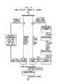
- FIG. 1is a block diagram showing a distributed information processing system having complex asset recovery functionality in an illustrative embodiment of the invention.
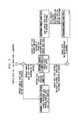
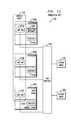
- FIGS. 2A, 2B and 2Cillustrate exemplary models of a complex asset in the FIG. 1 system.
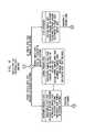
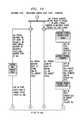
- FIGS. 3A and 3Bare flow diagrams showing portions of an exemplary complex asset recovery process implemented in the FIG. 1 system.
- FIG. 4shows an exemplary processing platform utilized to implement at least a portion of the FIG. 1 system.
- FIGS. 5-10are state transition diagrams illustrating lifecycle of an exemplary complex asset.
- FIG. 11is a diagram showing complex asset state transfer between production hosting platforms and recovery hosting platforms.
- FIGS. 12-19are block and flow diagrams illustrating the configuration and operation of an illustrative embodiment of the invention.
- distributed information processing systemas used herein is intended to be broadly construed, so as to encompass, for example, multi-site data centers, private or public cloud computing systems, grid computing systems, computing clusters, high performance computer systems or storage systems, as well as other types of systems comprising distributed information technology infrastructure.
- embodiments of the present inventionmay make use of one or more of the capture and/or revert techniques disclosed in U.S. patent application Ser. No. 13/077,213, filed Mar. 31, 2011 and entitled “Capture/Revert Module for Complex Assets of Distributed Information Technology Infrastructure,” and/or one or more of the sync point coordination techniques disclosed in U.S. patent application Ser. No. 12/827,400, filed Jun. 30, 2010 and entitled “Sync Point Coordination Providing High Throughput Job Processing Across Distributed Virtual Infrastructure,” which applications are commonly assigned herewith and incorporated by reference herein.
- use of such techniquesis not a requirement of any embodiment of the present invention.
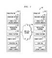
- FIG. 1shows a distributed information processing system 100 configured in accordance with an illustrative embodiment of the invention.
- the system 100comprises a production site 102 - 1 that communicates with a replica site 102 - 2 over a network 104 .
- the production and replica sites 102are examples of what are more generally referred to herein as respective first and second sites of a distributed information processing system. Numerous other types and arrangements of multiple sites may be used in other embodiments, and such sites may be configured to implement similar functionality.
- site 102 - 1is shown as a production site relative to replica site 102 - 2 in this embodiment, site 102 - 1 may additionally serve as a replica site relative to site 102 - 2 operating as a production site.
- a given one of the sites 102 - 1 or 102 - 2may be configured to serve as a replica site for each of multiple production sites of a distributed information processing system.
- the sites 102 - 1 and 102 - 2comprise respective protection appliances 105 - 1 and 105 - 2 implementing respective complex asset recovery managers 106 - 1 and 106 - 2 .
- the protection appliances 105are assumed in the present embodiment to be configured to support journaling functionality similar to that described in U.S. Pat. Nos. 7,516,287 and 7,627,612, both entitled “Methods and Apparatus for Optimal Journaling for Continuous Data Replication,” which are commonly assigned herewith and incorporated by reference herein.
- the complex asset recovery managers 106may in other embodiments be implemented at least in part using an external controller, that is, a controller that is external to one or both of the sites 102 .
- an external controllerneed not be part of any data recovery appliance, but may instead be part of a virtualization platform, a storage platform, a distributed resource management system, or another system component. Accordingly, the functionality associated with an external controller or other implementation of one or more complex asset recovery managers may be distributed over multiple system components, such that there is no single identifiable component providing all of the associated functionality.
- the sites 102 - 1 and 102 - 2further comprise respective virtualization platforms 107 - 1 and 107 - 2 , each of which may comprise one or more hypervisors.
- virtualization platforms 107 - 1 and 107 - 2each of which may comprise one or more hypervisors.
- An example of a commercially available virtualization platform that may be used in one or more embodiments of the inventionis the VMware® vSphereTM which may have an associated virtual infrastructure management system such as the VMware® vCenterTM.
- Other types of virtualization platforms that may be usedinclude Microsoft Hyper-V Server.
- the protection appliances 105may be implemented at least in part using respective hypervisors of the virtualization platforms 107 of the production and replica sites. At least one of the protection appliances 105 may comprise a splitter configured to facilitate replication of a given portion of a complex asset at the replica site.
- each of a plurality of hypervisors of the virtualization platform 107 - 1provides one or more virtual machines that collectively run a particular application at the production site 102 - 1 , and each of the hypervisors further comprises a separate splitter.
- the protection appliance 105 - 1may also be implemented on one of these hypervisors.
- the sites 102 - 1 and 102 - 2also comprise respective storage platforms 108 - 1 and 108 - 2 .
- These storage platformsmay be implemented, for example, using storage products such as VNX and Symmetrix VMAX, both commercially available from EMC Corporation of Hopkinton, Mass. A variety of other products may be utilized to implement at least a portion of the storage platforms 108 .
- storage platform functionalitymay be incorporated within a virtualization platform product.
- the complex asset recovery managers 106may be implemented in other elements of the sites 102 , such as in virtualization platforms 107 or storage platforms 108 of the sites.
- complex assets 110 - 1that illustratively include production virtual machines (VMs) 112 and production storage elements 114 .
- the replica site 102 - 2comprises corresponding complex assets 110 - 2 that include ghost virtual machines 116 corresponding to respective ones of the production virtual machines 112 and ghost storage elements 118 corresponding to respective ones of the production storage elements 114 .
- These virtual machines 116 and storage elements 118are referred to as respective “ghost” elements prior to bringing at least a portion of them into a fully operational status in conjunction with recovery of a failure in one of the corresponding complex assets 110 - 1 of the production site 102 - 1 .
- the protection appliances 105 and their associated complex asset recovery managers 106are utilized in configuring the ghost virtual machines 116 and ghost storage elements 118 of the replica site in a manner that facilitates recovery from a failure in one of the complex assets 110 - 1 of the production site.
- the protection appliances 105may each run on a computer, server or other processing platform element, which may be viewed as an example of what is more generally referred to herein as a “processing device.”
- FIG. 2Ashows an exemplary model 200 of a complex asset 202 in system 100 .
- a complex assetsuch as complex asset 202 illustratively comprises multiple simple assets 204 that have been logically assembled into a larger structure, where simple assets in the present embodiment generally comprise individual virtual machines or storage elements.
- the complex asset 202is shown in Unified Modeling Language (UML) format and comprises multiple simple assets 204 including one or more virtual machines 206 and one or more storage elements 208 .
- UMLUnified Modeling Language
- a given virtual machine 206may comprise, for example, elements such as virtual processor, virtual memory, virtual disk and virtual network interface card elements, respectively denoted in the figure as vCPU, vMemory, vDisk and vNIC elements.
- the given virtual machine 206is hosted by virtualization platform 210 , which is assumed to correspond to one of the virtualization platforms 107 - 1 or 107 - 2 of FIG. 1 .
- a given storage element 208may comprise, for example, elements such as metadata storage, cache memory and logical units (LUNs).
- the given storage element 208is served by storage platform 212 , which is assumed to correspond to one of the storage platforms 108 - 1 or 108 - 2 of FIG. 1 .
- Storage elements of a complex assetmay be provided using any of a number of different types of storage devices, including, by way of example, storage devices associated with direct attached storage (DAS), storage area networks (SANs), network attached storage (NAS), or other types of storage technologies.
- DASdirect attached storage
- SANsstorage area networks
- NASnetwork attached storage
- a given storage elementcan be associated with a virtual machine in many different ways.
- a storage elementthrough the hypervisor as a virtual disk (vDisk).
- This associationcan be made as: (1) a VMDK in a VMFS formatted data store, (2) a VMDK in an NFS formatted data store, and (3) a raw device map (RDM) of a LUN in virtual mode on a storage array.
- RDMraw device map
- Another possibilityis for the guest operating system to mount the storage element directly. For example through iSCSI, NFS, or a similar network enabled storage technology. In this case the storage element is outside the control and visibility of the virtualization platform.
- references herein to virtual hardware stateare intended to comprise all virtual machine devices that are virtualized and are to be transported to the replica site.
- a given complex assetmay be configured so as to comprise one or more virtual machines provided by one or more hypervisors of a virtualization platform, and at least one storage element provided by a storage platform. Accordingly, a complex asset may comprise multiple virtual machines and one or more associated external storage volumes that may or may not be visible to or controllable by a corresponding virtual machine hypervisor.
- storage elementas used herein is intended to be broadly construed so as to encompass a virtual disk provided by a virtualization platform, as well as a storage element provided by a storage platform but in a manner not visible to any hypervisor of the virtualization platform.
- the multiple virtual machines associated with a given complex assetmay comprise a set of virtual machines that are running a single application together. Numerous other arrangements of virtual machines and associated storage elements may be used in a complex asset as that term is broadly used herein.
- the complex asset model 200 of FIG. 2Afurther associates virtual machine 206 with a production virtual machine 214 and a ghost virtual machine 216 , each having a scheduled status as indicated.
- storage element 208is associated with a production storage element 218 and a ghost storage element 220 .
- the production virtual machine 214 and production storage element 218have a scheduled status of “1” and the ghost virtual machine 216 and the ghost storage element 220 have a scheduled status of “0.” This indicates that the complex asset is scheduled at the production site but not scheduled at the replica site. In the event of failure in the complex asset at the production site, the complex asset is recovered at the replica site and the associated scheduled statuses are reversed.
- complex asset 202 as illustrated in FIG. 2Ais merely an example, and numerous other types of complex assets may be subject to complex asset recovery using the techniques of the present invention.
- FIGS. 2B and 2Ccollectively illustrate another exemplary complex asset model, showing interaction with an external coordinator, which may illustratively comprise at least one of the complex asset recovery managers 105 .
- a given complex assetcomprises a first “portion” and a second “portion” although it is to be appreciated that it is a single complex asset of the type previously described in conjunction with one or more of FIGS. 2A, 2B and 2C that is referred to in this portion of the description.
- the first portion of the complex assetcomprises virtual hardware elements including but not limited to sets of virtual processor, virtual memory and virtual network interface elements of respective ones of a plurality of virtual machines provided by a virtualization platform
- the second portion of the complex assetcomprises at least one storage element surfaced through a storage platform of the first site, with the storage platform being external to the virtualization platform.
- the complex assetillustratively includes at least one storage element provided by a storage platform external to the virtualization platform.
- the second portionmay additionally include one or more storage elements provided by the virtualization platform, such that the second portion comprises multiple storage elements provided by the virtualization platform and the storage platform.
- the second portionmay comprise at least one of a first storage element comprising a virtual disk provided by the virtualization platform, and a second storage element provided by the storage platform.
- a first storage elementcomprising a virtual disk provided by the virtualization platform
- a second storage elementprovided by the storage platform.
- the complex assetis referred to as having these different first and second portions because such portions of the complex asset are handled differently in these exemplary processes associated with complex asset recovery in system 100 .
- the first portion comprising the virtual hardware elements of respective ones of the virtual machinesis subject to snapshot generation in the production site 102 - 1 and transfer of such snapshots from the production site to the replica site 102 - 2
- the second portion comprising the virtual disk provided by the virtualization platform or other storage elements provided by the storage platformis subject to replication in the replica site.
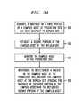
- the process as illustratedcomprises steps 300 through 306 , each of which will be described below.
- a snapshot of a first portion of a complex assetis generated at production site 102 - 1 and sent to the replica site 102 - 2 .
- this first portion of the complex assetillustratively includes sets of virtual processor, virtual memory and virtual network interface elements of respective ones of a plurality of virtual machines provided by virtualization platform 107 - 1 .
- the snapshot generationmay be configured such that an application running on the complex asset is not disrupted during the snapshot generation process.
- a second portion of the complex assetis replicated at the replica site 102 - 2 .
- the snapshot of the first portion of the complex asset generated and sent in step 300 and the replicated second portion of the complex asset from step 302are utilized at the replica site to preconfigure a ghost complex asset comprising one or more ghost virtual machines and one or more ghost storage elements in order to facilitate recovery at the replica site from a failure in the complex asset at the production site.
- steps 300 and 302may be performed in parallel with one another. It is important to recognize that these steps applied to respective first and second portions of a complex asset are not different serial processes, but are instead part of a unified process that takes a complex asset through multiple possible states. Examples of the states of a complex asset will be described in more detail below in conjunction with the state transition diagrams of FIGS. 5 through 10 . Transitions between these states may be based on a progression of simple asset hosting platform management tasks and phases.
- a replication processsuch as RecoverPoint from EMC Corporation may be used to provide replication between production and replica sites for storage elements surfaced through a hypervisor
- VNX Replicatorfrom EMC Corporation may be used to provide replication between production and recovery sites for storage elements mounted directly by a guest OS outside the visibility of the hypervisor.
- hypervisor-controlled storage elementsand externally-managed storage elements, respectively.
- Other types of replication processesmay additionally or alternatively be used, such as VPLEX, also commercially available from EMC Corporation.
- replicaatingused herein should be construed broadly, and may comprise one or more actions taken by the production site to cause a replica to be generated at a replica site, one or more actions taken by the replica site in generating a replica, or combinations of actions collectively involving both the production site and the replica site.
- the sending of the snapshot of a first portion of a complex asset to the replica site in step 300 and the replication of the second portion of the complex asset at the replica site in step 302may be configured and executed responsive to an initial user approval of the replica site as a recovery site for the complex asset.
- steps 300 and 302may first require that the user approve of a particular site to serve as the replica site for a particular complex asset of that user.
- the steps 300 and 302may be performed asynchronously relative to one another, while in other embodiments generating the snapshot of the first portion of the complex asset in step 300 and replicating the second portion of the complex asset in step 302 are coordinated such that the replicating occurs in conjunction with pausing of the virtual machines to generate the snapshot.
- some embodimentsmay include coordination between the snapshot generation and the storage element replication such that, for example, replication may be taken from the exact same point-in-time at which virtual machines of the complex asset were paused to generate the snapshot.
- Complex asset state information at the replica sitemay be updated as needed responsive to additional complex asset snapshots and replication information periodically received in the replica site from the production site. Accordingly, steps 300 and 302 may each be repeated periodically in order to maintain current complex asset state information in the replica site. This may involve periodically unloading complex asset state information at the replica site and loading newer complex asset state information.
- step 304the complex asset at the production site is monitored.
- This monitoringis illustratively performed by at least one of the complex asset recovery managers 106 , which as noted above may be implemented at least in part as an external controller relative to the production and replica sites.
- step 306responsive to detection of a failure in the complex asset at the production site, the complex asset is recovered at the replica site utilizing the snapshot of the first portion of the complex asset and the replicated second portion of the complex asset.
- recovery of the complex asset at the second siteis triggered responsive to detection of a failure in the complex asset at the first site. Preloading of the ghost complex asset at the replica site allows this recovery to be achieved almost immediately upon detection of a failure, as described in more detail elsewhere herein.
- the snapshot sent from the production site 102 - 1 to the replica site 102 - 2 in step 300may be sent from protection appliance 105 - 1 to protection appliance 105 - 2 .
- journal processorsimplemented in respective ones of the complex asset recovery managers 106 , with the journal processors being configured in a manner similar to that described in the above-cited U.S. Pat. Nos. 7,516,287 and 7,627,612.
- the journal processorsmay be more particularly configured to maintain respective recovery journals comprising complex asset state information at the respective production and replica sites.
- the snapshotmay be sent at least in part in metadata transmitted from the journal processor at the production site to the journal processor at the replica site, with the metadata comprising a complex asset bookmark including a pointer to one or more snapshot files.
- the snapshot of the first portion of the complex assetmay therefore be generated in a manner that allows recovery to a particular point-in-time based on selection of the point-in-time from a journal.
- the snapshot generated and sent in step 300comprises information characterizing memory state of the one or more virtual machines of the complex asset and does not include information characterizing memory state of any complex asset storage element that is replicated at the replica site in step 302 .
- the snapshot generated and sent in step 300comprises information characterizing memory state of the one or more virtual machines of the complex asset and does not include information characterizing memory state of any complex asset storage element that is replicated at the replica site in step 302 .
- a given snapshot generated by the production sitemay be erased at the production site after being sent to the replica site. This ability to erase snapshots advantageously ensures that maintenance of snapshots at the production site does not adversely impact storage performance at the production site.
- an exemplary process associated with complex asset recoveryincludes steps 310 through 316 .
- the replica site 102 - 2receives a snapshot of the first portion of a complex asset from the production site 102 - 1 .
- the snapshotis generated in the manner previously described.
- step 312the second portion of the complex asset is replicated at the replica site, also as previously described.
- steps 310 and 312may be performed in parallel with one another.
- the received snapshot of the first portion of the complex assetis used to configure one or more virtual machines of the complex asset in a paused state at the replica site. This may more particularly involve preloading a plurality of ghost virtual machines of a ghost complex asset at the replica site up to the paused state.
- the replicated second portion of the complex assetis used to configure one or more storage elements of the second portion of the complex asset in a state consistent with the paused state of the one or more virtual machines of the first portion of the complex asset at the replica site.
- the consistent state of the one or more replicated storage elementsmay correspond to a replicated point-in-time that corresponds to a capture time of the snapshot.
- step 316the one or more paused virtual machines of the complex asset at the replica site are resumed responsive to detection of a failure in the complex asset at the production site. This may more particularly involve simultaneously resuming the plurality of ghost virtual machines of the ghost complex asset at the replica site.
- the one or more resumed virtual machinesoperate with the one or more configured storage elements so as to provide application consistent recovery of the complex asset.
- Substantially continuous replication of the second portion of the complex assetmay be provided at the second site in order to support rollback of the associated storage elements to any desired point-in-time.
- one or more ghost storage elementsare also rolled back to a particular point-in-time, so as to be ready to resume from the point-in-time.
- the pausing and resuming of virtual machines at the replica site in respective steps 314 and 316 in conjunction with rollback of the replicated storage elementsallows substantially immediate recovery of the complex asset at the replica site based on current complex asset state information maintained at the replica site via the previously-described snapshot and replication mechanisms.
- the ghost virtual machinesare brought up from the latest point-in-time which includes the full complex asset state.
- alternative mechanismsmay be used to provide current complex asset state information to the replica site so as to support substantially immediate recovery responsive to a detected failure in the complex asset at the production site.
- the failuremay be detected using one or more of the complex asset recovery managers 106 , which may be implemented in the form of an external controller.
- an external controllermay comprise a monitoring device that is external to both the production and replica sites.
- the monitoring devicein some embodiments serves as an arbiter that monitors the complex asset at the production site and the corresponding ghost complex asset at the replica site, and upon determining that a failure has occurred in the complex asset at the production side triggers the resuming of the ghost virtual machines of the ghost complex asset at the replica site.
- the replica sitereceives a recovery request from the external controller or another system element, rolls back one or more replicated storage elements of the complex asset at the replica site to a designated point-in-time, and schedules virtual processors of the one or more virtual machines of the complex asset at the replica site for operation utilizing the rolled back replicated storage elements.
- failure detection and recovery arrangementsare possible in other embodiments.
- only a subset of the virtual machines of the complex assetfail, although this is illustratively considered a failure of the entire complex asset.
- the complex assetmay be restarted on a different set of servers at the same site, using snapshot generation and replication management techniques of a type similar to those disclosed herein for use across production and replica sites.
- embodiments of the present inventionmay be configured to perform failure detection and recovery at a single site of an information processing system.
- Failure recovery at the second sitemay involve recovering network communication between ghost compute and ghost storage elements.
- algorithms for network communication recovery to ensure lossless network communication between compute and storage elementsmay be involved in complex asset recovery on the second site. This is applicable to both physical networks and software defined networks.
- FIGS. 3A and 3Bare presented by way of illustrative example only, and should not be construed as limiting the scope of the invention in any way.
- Alternative embodimentscan use other types of processing operations for recovering complex assets as disclosed herein.
- the ordering of the process stepsmay be varied in other embodiments, or certain steps may be performed concurrently with one another rather than serially.
- at least a subset of the process stepsmay be repeated periodically, possibly in accordance with an established schedule of snapshot generation and storage element replication as configured to facilitate complex asset recovery.
- the distributed information processing system 100is assumed to be implemented using multiple processing platforms.
- each of the sites 102may be implemented using a different set of one or more processing platforms.
- the processing platform 400in this embodiment comprises a portion of the system 100 and includes a plurality of processing devices, denoted 402 - 1 , 402 - 2 , 402 - 3 , . . . 402 -K, which communicate with one another over a network 404 .
- the network 404may comprise any type of network, such as the Internet, a WAN, a LAN, a satellite network, a telephone or cable network, a cellular network, a wireless network such as WiFi or WiMAX, or various portions or combinations of these and other types of networks.
- the processing device 402 - 1 in the processing platform 400comprises a processor 410 coupled to a memory 412 .
- the processor 410may comprise a microprocessor, a microcontroller, an application-specific integrated circuit (ASIC), a field-programmable gate array (FPGA) or other type of processing circuitry, as well as portions or combinations of such circuitry elements, and the memory 412 , which may be viewed as an example of a “processor-readable storage medium” having executable computer program code or other software programs embodied therein, may comprise random access memory (RAM), read-only memory (ROM) or other types of memory, in any combination.
- RAMrandom access memory
- ROMread-only memory
- Articles of manufacturecomprising such processor-readable storage media are considered embodiments of the present invention.
- a given such article of manufacturemay comprise, for example, a storage device such as a storage disk, a storage array or an integrated circuit containing memory.
- the term “article of manufacture” as used hereinshould be understood to exclude transitory, propagating signals.
- network interface circuitry 414which is used to interface the processing device with the network 404 and other system components, and may comprise conventional transceivers.
- the other processing devices 402 of the processing platform 400are assumed to be configured in a manner similar to that shown for processing device 402 - 1 in the figure.
- processing platform 400 shown in the figureis presented by way of example only, and system 100 may include additional or alternative processing platforms, as well as numerous distinct processing platforms in any combination, with each such platform comprising one or more computers, servers, storage devices or other processing devices.
- FIGS. 5 through 10state diagrams are shown illustrating the lifetime of a complex asset in an illustrative embodiment. It should be understood that the states and associated transitions are exemplary only, and may be varied in other embodiments.
- FIG. 5shows the complete state diagram for complex asset life in the present embodiment. From an Off state, the complex asset can transition to a Powering On state. The Off state is entered from a Powering Down state. Additional states of the complex asset include Running, Capturing State, Failure and Recovering State.
- FIGS. 6, 7 and 8show more detailed views of Powering On, Capturing State and Recovering State, respectively.
- the Powering On diagram of FIG. 6should be viewed in conjunction with FIG. 16 .
- the left side of the state diagram of FIG. 6illustrates recovery of the virtual machines of the complex asset from a paused state. At least a portion of the virtual machines are loaded with previous runtime state, while one or more of the virtual machines may be powered without loading previous runtime state, as indicated in the figure.
- the right side of the state diagram of FIG. 6illustrates rollback of one or more storage volumes of the complex asset to a particular point-in-time. One or more of the storage volumes may already be in the correct state and therefore are not subject to rolling back.
- the Capturing State diagram of FIG. 7involves determining: (a) if state is currently being captured, (b) if target hosting platforms are the current hosting platforms, and (c) if state must be transferred and preloaded for failover.
- the process of failover preparationinvolves the complex asset transitioning between Capturing Complex Asset State, Transferring Complex Asset State, and Preloading Complex Asset State.
- Capturing Complex Asset Stateillustrated in detail in FIG. 9 , provides capture functionality similar to that described in the above-cited U.S. patent application Ser. No. 13/077,213.
- FIG. 9should be viewed in conjunction with FIG. 15 .
- step 1504 of FIG. 15relates to persisting of storage elements in FIG. 9 .
- Preloading Complex Asset Stateillustrated in detail in FIG. 10 , provides revert functionality similar to that described in the above-cited U.S. patent application Ser. No. 13/077,213. However, in the case of preloading, a complex asset simply remains in an All VMs Paused state on the recovery hosts until a failure is encountered on the production hosting platforms. The above-noted external controller detects a failure and triggers the transition from All VMs Paused to an All VMs Powered On state.
- This transitionmay be viewed as substantially immediate, providing a substantially true-zero or pseudo-true-zero recovery time transition, as the ghost virtual machines are in a paused state ready for immediate scheduling on the virtualization platform, and the associated ghost storage elements are rolled back and ready to resume, in the manner previously described.
- FIG. 10generally illustrates the preloading of the ghost complex asset at the replica site and should be viewed in conjunction with FIG. 19 .
- the systemis configured to detect the failure and trigger the recovery. Once the external controller determines a recovery is required, the transition from Failure to Recovering State involves determining if the simple assets are in the correct state on their hosting platforms, loading previous state into hosting platforms if required by transitioning into the Preloading Complex Asset State, and finally transitioning from All VMs Paused to All VMs Powered On.
- captured statemay be moved solely by the hosting platforms (e.g., virtualization and storage platforms) between the production and replica sites.
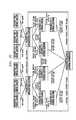
- An exemplary arrangement of this typeis illustrated in FIG. 11 , which shows a portion 1100 of system 100 including production hosting platforms 1102 - 1 and recovery hosting platforms 1102 - 2 .
- the production hosting platforms 1102 - 1which may correspond to portions of virtualization and storage platforms 107 - 1 and 108 - 1 of FIG. 1 , comprise a set of processing devices 1104 - 1 .
- the recovery hosting platforms 1102 - 2which may correspond to portions of virtualization and storage platforms 107 - 2 and 108 - 2 of FIG.
- compute element state associated with virtual hardwaree.g., vCPU, vMemory, vNIC
- vCPUvCPU
- vMemoryvNIC
- captured statemay instead be moved by moving compute element state associated with virtual hardware such as vCPU, vMemory and vNIC between the production and replica sites, and associating a point-in-time state index with replicated storage elements between the production and replica sites.
- the point-in-time storage element state indexmay be taken in conjunction with Storage Elements Ready in Preloading Complex Asset State as illustrated in FIG. 10 .
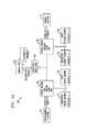
- FIGS. 12-19Another illustrative embodiment will now be described with reference to FIGS. 12-19 .
- This embodimentmay be viewed as a particular implementation of the distributed information processing system 100 previously described.
- a production site 1200 of the system in this embodimentcomprises multiple hypervisors 1205 A, 1205 B and 1205 C running respective application virtual machines (appVMs) 1210 A, 1210 B and 1210 C of a complex asset 1210 .
- the virtual machinesare coupled via their respective hypervisors to SAN switches 1220 to storage arrays 1222 and 1224 .
- the hypervisorsinclude respective splitters 1225 A, 1225 B and 1225 C with the splitters illustratively being arranged within a kernel space of their respective hypervisors, as opposed to a user space of the respective hypervisors.
- the first hypervisor 1205 Ais also running a virtual machine that executes code of a protection appliance 1226 of the type previously described herein.
- FIG. 13illustrates replication in the system using production site 1200 coupled to replica site 1300 via WAN 1304 .
- the protection appliance 1226 of the hypervisor 1205 A at the production site 1200comprises a journal processor 1227 .
- the production sitefurther comprises a data store 1250 implemented within production storage array 1222 .
- the replica site 1300includes hypervisor 1305 A that is coupled via switch 1320 to a target storage array 1322 .
- the hypervisor 1305 Acomprises splitter 1325 A and protection appliance 1326 .
- the protection appliance 1326incorporates a journal processor 1327 .
- the target storage array 1322comprises a data store 1350 .
- the data store 1250 of the production site 1200comprises virtual disks of the virtual machine 1210 and associated journal files maintained for the virtual disks. These virtual disks are replicated in the data store 1350 of the replica site.
- the journal filescontain change information configured to allow point-in-time recovery of the virtual disks.
- additional filesillustratively virtual machine snapshot (vmsn) files, which contain state information associated with a current snapshot provided by the production site to the replica site as previously described.
- FIG. 14shows one possible configuration of a journal in the data store 1350 of the replica site 1300 .
- the journal in this examplecomprises a DO journal similar to that described in the above-cited U.S. Pat. Nos. 7,516,287 and 7,627,612, but having DO metadata that is modified so as to include complex asset bookmarks 1400 - 1 and 1400 - 2 each comprising information illustratively including a pointer to a vmsn file and possibly other configuration files within the data store 1350 .
- the vmsn file and other files containing complex asset state informationmay be stored within a journal volume rather than on a separate data store of the type shown in FIG. 13 .
- FIG. 15a process for the creation of a complex asset bookmark is illustrated.
- the processincludes steps 1500 through 1508 . This figure should be viewed in conjunction with the state diagram of FIG. 9 .
- step 1500the system receives a request to create a complex asset bookmark.
- Thismay be an automatic request generated in accordance with a specified periodic time configuration, or a user request.
- the complex asset snapshotis created.
- Thismay involve use of capture techniques of the type described in the above-cited U.S. patent application Ser. No. 13/077,213, but modified such that upon capture of virtual machine state, a replication engine controlling capture of other storage element state is directed to create a bookmark.
- a replication engine controlling capture of other storage element stateis directed to create a bookmark.
- Such an arrangementprovides coordination between capture of state for virtual machine elements and capture of state for other storage elements associated with the virtual machines in a given complex asset but not surfaced through the corresponding hypervisors.
- the bookmark in this embodimentis created after storage elements are prepared.
- step 1504the bookmark is written to the replica journal at the replica site.
- a background processcopies the rest of the complex asset state to the replica site.
- the bookmarkpoints to the data at the replica site, which as indicated above may include the vmsn file indicating the current state of virtual machine hardware such as vCPU, vMemory and vNIC.
- step 1508a determination is made as to whether or not the user wants to keep the complex asset snapshot at the production site. If not, the snapshot is erased at the production site as indicated in step 1510 .
- FIG. 16shows a process for recovering a point-in-time (“pit”) at the replica site using the complex asset snapshot and its associated bookmark.
- the processincludes steps 1600 through 1610 . This figure should be viewed in conjunction with the state diagram of FIG. 6 .
- step 1600the user requests recovery of a point-in-time for a complex asset.
- step 1602a determination is made as to whether or not the requested point-in-time has a corresponding complex asset snapshot. If not, just the replicated storage elements are rolled back to the point-in-time in step 1604 . Otherwise, the full complex asset state is available and the complex asset in its entirety is rolled back to the point-in-time as indicated in step 1606 . This involves reconfiguring the replica site virtual machines in step 1608 in accordance with the appropriate snapshot utilizing the relevant vmsn files.
- step 1610the complex asset is resumed. This involves resuming the paused virtual machines as previously described.
- FIG. 17shows a portion of the replica site 1300 including hypervisor 1305 A and storage array 1322 with data store 1350 .
- the complex asset at the replica siteincludes two virtual machines VM 1 and VM 2 that are almost up but in a paused state. These virtual machines include respective virtual disks VMDK 1 and VMDK 2 in the data store 1350 that are surfaced through the hypervisor 1305 A. These are configured in accordance with replicated versions of these storage elements, indicated in the figure as “last” versions of VMDK 1 and VMDK 2 , as well as other “older” versions.
- FIG. 18shows one example of an external controller in the form of a third site watchdog process 1800 that monitors the production site 1200 and the replica site 1300 using check alive communications as indicated.
- the watchdog processdiscovers that the production site is down or otherwise detects a failure in the complex asset at the production site, it will trigger generation of a resume command at the replica site and the paused virtual machines will resume running from the last complex asset state.
- an external controllermay be implemented in the form of a monitoring device that runs externally to at least one of the production and replica sites.
- a similar controllermay be implemented in one or both of the complex asset recovery managers 106 of FIG. 1 .
- the processincludes steps 1900 through 1906 .
- step 1900a complex asset snapshot is copied to the replica site.
- a partial recovery or preloading of the complex assetis performed, in accordance with the state diagram of FIG. 10 , up to a step just before resume, such that the virtual machines are paused and ready to resume upon detection of a failure at the production site.
- step 1904If a failure is detected in the complex asset at the production site in step 1904 , the complex asset virtual machines at the replica site are resumed as indicated in step 1906 .
- Illustrative embodiments of the inventioncan advantageously provide application consistent replication as well as substantially true-zero application recovery time in the event of complex asset failure.
- complex asset recovery functionalitysuch as that described above can be implemented at least in part in the form of one or more software programs stored in memory and executed by a processor of a processing device such as a computer or server.
- a processor of a processing devicesuch as a computer or server.
- a memory or other storage device having such program code embodied thereinis an example of what is more generally referred to herein as a “machine-readable storage medium.”
Landscapes
- Engineering & Computer Science (AREA)
- Databases & Information Systems (AREA)
- Theoretical Computer Science (AREA)
- Computing Systems (AREA)
- Data Mining & Analysis (AREA)
- Physics & Mathematics (AREA)
- General Engineering & Computer Science (AREA)
- General Physics & Mathematics (AREA)
- Hardware Redundancy (AREA)
Abstract
Description
Claims (20)
Priority Applications (1)
| Application Number | Priority Date | Filing Date | Title |
|---|---|---|---|
| US14/041,795US9552405B1 (en) | 2013-09-30 | 2013-09-30 | Methods and apparatus for recovery of complex assets in distributed information processing systems |
Applications Claiming Priority (1)
| Application Number | Priority Date | Filing Date | Title |
|---|---|---|---|
| US14/041,795US9552405B1 (en) | 2013-09-30 | 2013-09-30 | Methods and apparatus for recovery of complex assets in distributed information processing systems |
Publications (1)
| Publication Number | Publication Date |
|---|---|
| US9552405B1true US9552405B1 (en) | 2017-01-24 |
Family
ID=57794992
Family Applications (1)
| Application Number | Title | Priority Date | Filing Date |
|---|---|---|---|
| US14/041,795Active2034-07-30US9552405B1 (en) | 2013-09-30 | 2013-09-30 | Methods and apparatus for recovery of complex assets in distributed information processing systems |
Country Status (1)
| Country | Link |
|---|---|
| US (1) | US9552405B1 (en) |
Cited By (57)
| Publication number | Priority date | Publication date | Assignee | Title |
|---|---|---|---|---|
| US9665305B1 (en) | 2015-06-26 | 2017-05-30 | EMC IP Holding Company LLC | Tiering data between two deduplication devices |
| US9678680B1 (en) | 2015-03-30 | 2017-06-13 | EMC IP Holding Company LLC | Forming a protection domain in a storage architecture |
| US9910621B1 (en) | 2014-09-29 | 2018-03-06 | EMC IP Holding Company LLC | Backlogging I/O metadata utilizing counters to monitor write acknowledgements and no acknowledgements |
| US9910735B1 (en) | 2016-03-30 | 2018-03-06 | EMC IP Holding Company LLC | Generating an application-consistent snapshot |
| US10019194B1 (en) | 2016-09-23 | 2018-07-10 | EMC IP Holding Company LLC | Eventually consistent synchronous data replication in a storage system |
| US10031703B1 (en) | 2013-12-31 | 2018-07-24 | Emc Corporation | Extent-based tiering for virtual storage using full LUNs |
| US10042751B1 (en) | 2015-09-30 | 2018-08-07 | EMC IP Holding Company LLC | Method and system for multi-tier all-flash array |
| US10055148B1 (en) | 2015-12-22 | 2018-08-21 | EMC IP Holding Company LLC | Storing application data as an enhanced copy |
| US10061666B1 (en) | 2011-12-30 | 2018-08-28 | Emc International Company | Method and apparatus for adding a director to storage with network-based replication without data resynchronization |
| US10067837B1 (en) | 2015-12-28 | 2018-09-04 | EMC IP Holding Company LLC | Continuous data protection with cloud resources |
| US10078459B1 (en) | 2016-09-26 | 2018-09-18 | EMC IP Holding Company LLC | Ransomware detection using I/O patterns |
| US10082980B1 (en) | 2014-06-20 | 2018-09-25 | EMC IP Holding Company LLC | Migration of snapshot in replication system using a log |
| US10101943B1 (en) | 2014-09-25 | 2018-10-16 | EMC IP Holding Company LLC | Realigning data in replication system |
| US10114581B1 (en) | 2016-12-27 | 2018-10-30 | EMC IP Holding Company LLC | Creating a virtual access point in time on an object based journal replication |
| US10133874B1 (en) | 2015-12-28 | 2018-11-20 | EMC IP Holding Company LLC | Performing snapshot replication on a storage system not configured to support snapshot replication |
| US10140039B1 (en) | 2016-12-15 | 2018-11-27 | EMC IP Holding Company LLC | I/O alignment for continuous replication in a storage system |
| US10146961B1 (en) | 2016-09-23 | 2018-12-04 | EMC IP Holding Company LLC | Encrypting replication journals in a storage system |
| US10152267B1 (en) | 2016-03-30 | 2018-12-11 | Emc Corporation | Replication data pull |
| US10191687B1 (en) | 2016-12-15 | 2019-01-29 | EMC IP Holding Company LLC | Adaptive snap-based replication in a storage system |
| US10210073B1 (en) | 2016-09-23 | 2019-02-19 | EMC IP Holding Company, LLC | Real time debugging of production replicated data with data obfuscation in a storage system |
| US10223023B1 (en) | 2016-09-26 | 2019-03-05 | EMC IP Holding Company LLC | Bandwidth reduction for multi-level data replication |
| US10229006B1 (en) | 2015-12-28 | 2019-03-12 | EMC IP Holding Company LLC | Providing continuous data protection on a storage array configured to generate snapshots |
| US10235090B1 (en) | 2016-09-23 | 2019-03-19 | EMC IP Holding Company LLC | Validating replication copy consistency using a hash function in a storage system |
| US10235088B1 (en) | 2016-03-30 | 2019-03-19 | EMC IP Holding Company LLC | Global replication policy for multi-copy replication |
| US10235061B1 (en) | 2016-09-26 | 2019-03-19 | EMC IP Holding Company LLC | Granular virtual machine snapshots |
| US10235247B1 (en) | 2016-09-26 | 2019-03-19 | EMC IP Holding Company LLC | Compressing memory snapshots |
| US10235091B1 (en) | 2016-09-23 | 2019-03-19 | EMC IP Holding Company LLC | Full sweep disk synchronization in a storage system |
| US10235064B1 (en) | 2016-12-27 | 2019-03-19 | EMC IP Holding Company LLC | Optimized data replication using special NVME protocol and running in a friendly zone of storage array |
| US10235060B1 (en) | 2016-04-14 | 2019-03-19 | EMC IP Holding Company, LLC | Multilevel snapshot replication for hot and cold regions of a storage system |
| US10235145B1 (en) | 2012-09-13 | 2019-03-19 | Emc International Company | Distributed scale-out replication |
| US10235196B1 (en) | 2015-12-28 | 2019-03-19 | EMC IP Holding Company LLC | Virtual machine joining or separating |
| US10235087B1 (en) | 2016-03-30 | 2019-03-19 | EMC IP Holding Company LLC | Distributing journal data over multiple journals |
| US10235092B1 (en) | 2016-12-15 | 2019-03-19 | EMC IP Holding Company LLC | Independent parallel on demand recovery of data replicas in a storage system |
| US10296419B1 (en) | 2015-03-27 | 2019-05-21 | EMC IP Holding Company LLC | Accessing a virtual device using a kernel |
| US10324637B1 (en) | 2016-12-13 | 2019-06-18 | EMC IP Holding Company LLC | Dual-splitter for high performance replication |
| US10324798B1 (en) | 2014-09-25 | 2019-06-18 | EMC IP Holding Company LLC | Restoring active areas of a logical unit |
| US10353603B1 (en) | 2016-12-27 | 2019-07-16 | EMC IP Holding Company LLC | Storage container based replication services |
| US10366011B1 (en) | 2018-05-03 | 2019-07-30 | EMC IP Holding Company LLC | Content-based deduplicated storage having multilevel data cache |
| US10409787B1 (en) | 2015-12-22 | 2019-09-10 | EMC IP Holding Company LLC | Database migration |
| US10409629B1 (en) | 2016-09-26 | 2019-09-10 | EMC IP Holding Company LLC | Automated host data protection configuration |
| US10409986B1 (en) | 2016-09-26 | 2019-09-10 | EMC IP Holding Company LLC | Ransomware detection in a continuous data protection environment |
| US10423634B1 (en) | 2016-12-27 | 2019-09-24 | EMC IP Holding Company LLC | Temporal queries on secondary storage |
| US10437783B1 (en) | 2014-09-25 | 2019-10-08 | EMC IP Holding Company LLC | Recover storage array using remote deduplication device |
| US10467102B1 (en) | 2016-12-15 | 2019-11-05 | EMC IP Holding Company LLC | I/O score-based hybrid replication in a storage system |
| US10489321B1 (en) | 2018-07-31 | 2019-11-26 | EMC IP Holding Company LLC | Performance improvement for an active-active distributed non-ALUA system with address ownerships |
| US10496487B1 (en) | 2014-12-03 | 2019-12-03 | EMC IP Holding Company LLC | Storing snapshot changes with snapshots |
| US10579282B1 (en) | 2016-03-30 | 2020-03-03 | EMC IP Holding Company LLC | Distributed copy in multi-copy replication where offset and size of I/O requests to replication site is half offset and size of I/O request to production volume |
| US10592166B2 (en) | 2018-08-01 | 2020-03-17 | EMC IP Holding Company LLC | Fast input/output in a content-addressable storage architecture with paged metadata |
| US10628268B1 (en) | 2016-12-15 | 2020-04-21 | EMC IP Holding Company LLC | Proof of data replication consistency using blockchain |
| US10713221B2 (en) | 2018-07-30 | 2020-07-14 | EMC IP Holding Company LLC | Dual layer deduplication for a file system running over a deduplicated block storage |
| US10747606B1 (en) | 2016-12-21 | 2020-08-18 | EMC IP Holding Company LLC | Risk based analysis of adverse event impact on system availability |
| US10747667B2 (en) | 2018-11-02 | 2020-08-18 | EMC IP Holding Company LLC | Memory management of multi-level metadata cache for content-based deduplicated storage |
| US10776211B1 (en) | 2016-12-27 | 2020-09-15 | EMC IP Holding Company LLC | Methods, systems, and apparatuses to update point in time journal using map reduce to create a highly parallel update |
| US10853181B1 (en) | 2015-06-29 | 2020-12-01 | EMC IP Holding Company LLC | Backing up volumes using fragment files |
| US11093158B2 (en) | 2019-01-29 | 2021-08-17 | EMC IP Holding Company LLC | Sub-lun non-deduplicated tier in a CAS storage to reduce mapping information and improve memory efficiency |
| US11704164B1 (en)* | 2018-08-31 | 2023-07-18 | Veritas Technologies Llc | Intelligent and automatic load balancing of workloads on replication appliances based on appliance load scores |
| US12164480B2 (en) | 2019-03-28 | 2024-12-10 | EMC IP Holding Company LLC | Optimizing file system defrag for deduplicated block storage |
Citations (8)
| Publication number | Priority date | Publication date | Assignee | Title |
|---|---|---|---|---|
| US7516287B2 (en) | 2006-09-28 | 2009-04-07 | Emc Israel Development Center, Ltd. | Methods and apparatus for optimal journaling for continuous data replication |
| US20090260007A1 (en)* | 2008-04-15 | 2009-10-15 | International Business Machines Corporation | Provisioning Storage-Optimized Virtual Machines Within a Virtual Desktop Environment |
| US7627612B2 (en) | 2006-09-28 | 2009-12-01 | Emc Israel Development Center, Ltd. | Methods and apparatus for optimal journaling for continuous data replication |
| US20100107158A1 (en)* | 2008-10-28 | 2010-04-29 | Vmware, Inc. | Low overhead fault tolerance through hybrid checkpointing and replay |
| US20110010515A1 (en)* | 2009-07-09 | 2011-01-13 | Microsoft Corporation | Backup of virtual machines using cloned virtual machines |
| US20130262801A1 (en)* | 2011-09-30 | 2013-10-03 | Commvault Systems, Inc. | Information management of virtual machines having mapped storage devices |
| US8621274B1 (en)* | 2011-05-18 | 2013-12-31 | Netapp Inc. | Virtual machine fault tolerance |
| US9047238B2 (en)* | 2012-11-28 | 2015-06-02 | Red Hat Israel, Ltd. | Creating a virtual machine from a snapshot |
- 2013
- 2013-09-30USUS14/041,795patent/US9552405B1/enactiveActive
Patent Citations (8)
| Publication number | Priority date | Publication date | Assignee | Title |
|---|---|---|---|---|
| US7516287B2 (en) | 2006-09-28 | 2009-04-07 | Emc Israel Development Center, Ltd. | Methods and apparatus for optimal journaling for continuous data replication |
| US7627612B2 (en) | 2006-09-28 | 2009-12-01 | Emc Israel Development Center, Ltd. | Methods and apparatus for optimal journaling for continuous data replication |
| US20090260007A1 (en)* | 2008-04-15 | 2009-10-15 | International Business Machines Corporation | Provisioning Storage-Optimized Virtual Machines Within a Virtual Desktop Environment |
| US20100107158A1 (en)* | 2008-10-28 | 2010-04-29 | Vmware, Inc. | Low overhead fault tolerance through hybrid checkpointing and replay |
| US20110010515A1 (en)* | 2009-07-09 | 2011-01-13 | Microsoft Corporation | Backup of virtual machines using cloned virtual machines |
| US8621274B1 (en)* | 2011-05-18 | 2013-12-31 | Netapp Inc. | Virtual machine fault tolerance |
| US20130262801A1 (en)* | 2011-09-30 | 2013-10-03 | Commvault Systems, Inc. | Information management of virtual machines having mapped storage devices |
| US9047238B2 (en)* | 2012-11-28 | 2015-06-02 | Red Hat Israel, Ltd. | Creating a virtual machine from a snapshot |
Non-Patent Citations (2)
| Title |
|---|
| U.S. Appl. No. 12/827,400, filed in the name of James J. Moore et al. on Jun. 30, 2010 and entitled "Sync Point Coordination Providing High Throughput Job Processing Across Distributed Virtual Infrastructure." |
| U.S. Appl. No. 13/077,213, filed in the name of James J. Moore et al. on Mar. 31, 2011 and entitled "Capture/Revert Module for Complex Assets of Distributed Information Technology Infrastructure." |
Cited By (60)
| Publication number | Priority date | Publication date | Assignee | Title |
|---|---|---|---|---|
| US10061666B1 (en) | 2011-12-30 | 2018-08-28 | Emc International Company | Method and apparatus for adding a director to storage with network-based replication without data resynchronization |
| US10235145B1 (en) | 2012-09-13 | 2019-03-19 | Emc International Company | Distributed scale-out replication |
| US10031703B1 (en) | 2013-12-31 | 2018-07-24 | Emc Corporation | Extent-based tiering for virtual storage using full LUNs |
| US10082980B1 (en) | 2014-06-20 | 2018-09-25 | EMC IP Holding Company LLC | Migration of snapshot in replication system using a log |
| US10324798B1 (en) | 2014-09-25 | 2019-06-18 | EMC IP Holding Company LLC | Restoring active areas of a logical unit |
| US10437783B1 (en) | 2014-09-25 | 2019-10-08 | EMC IP Holding Company LLC | Recover storage array using remote deduplication device |
| US10101943B1 (en) | 2014-09-25 | 2018-10-16 | EMC IP Holding Company LLC | Realigning data in replication system |
| US9910621B1 (en) | 2014-09-29 | 2018-03-06 | EMC IP Holding Company LLC | Backlogging I/O metadata utilizing counters to monitor write acknowledgements and no acknowledgements |
| US10496487B1 (en) | 2014-12-03 | 2019-12-03 | EMC IP Holding Company LLC | Storing snapshot changes with snapshots |
| US10296419B1 (en) | 2015-03-27 | 2019-05-21 | EMC IP Holding Company LLC | Accessing a virtual device using a kernel |
| US9678680B1 (en) | 2015-03-30 | 2017-06-13 | EMC IP Holding Company LLC | Forming a protection domain in a storage architecture |
| US9665305B1 (en) | 2015-06-26 | 2017-05-30 | EMC IP Holding Company LLC | Tiering data between two deduplication devices |
| US10853181B1 (en) | 2015-06-29 | 2020-12-01 | EMC IP Holding Company LLC | Backing up volumes using fragment files |
| US10042751B1 (en) | 2015-09-30 | 2018-08-07 | EMC IP Holding Company LLC | Method and system for multi-tier all-flash array |
| US10055148B1 (en) | 2015-12-22 | 2018-08-21 | EMC IP Holding Company LLC | Storing application data as an enhanced copy |
| US10409787B1 (en) | 2015-12-22 | 2019-09-10 | EMC IP Holding Company LLC | Database migration |
| US10067837B1 (en) | 2015-12-28 | 2018-09-04 | EMC IP Holding Company LLC | Continuous data protection with cloud resources |
| US10229006B1 (en) | 2015-12-28 | 2019-03-12 | EMC IP Holding Company LLC | Providing continuous data protection on a storage array configured to generate snapshots |
| US10133874B1 (en) | 2015-12-28 | 2018-11-20 | EMC IP Holding Company LLC | Performing snapshot replication on a storage system not configured to support snapshot replication |
| US10235196B1 (en) | 2015-12-28 | 2019-03-19 | EMC IP Holding Company LLC | Virtual machine joining or separating |
| US10579282B1 (en) | 2016-03-30 | 2020-03-03 | EMC IP Holding Company LLC | Distributed copy in multi-copy replication where offset and size of I/O requests to replication site is half offset and size of I/O request to production volume |
| US10152267B1 (en) | 2016-03-30 | 2018-12-11 | Emc Corporation | Replication data pull |
| US10235088B1 (en) | 2016-03-30 | 2019-03-19 | EMC IP Holding Company LLC | Global replication policy for multi-copy replication |
| US9910735B1 (en) | 2016-03-30 | 2018-03-06 | EMC IP Holding Company LLC | Generating an application-consistent snapshot |
| US10235087B1 (en) | 2016-03-30 | 2019-03-19 | EMC IP Holding Company LLC | Distributing journal data over multiple journals |
| US10235060B1 (en) | 2016-04-14 | 2019-03-19 | EMC IP Holding Company, LLC | Multilevel snapshot replication for hot and cold regions of a storage system |
| US10210073B1 (en) | 2016-09-23 | 2019-02-19 | EMC IP Holding Company, LLC | Real time debugging of production replicated data with data obfuscation in a storage system |
| US10235091B1 (en) | 2016-09-23 | 2019-03-19 | EMC IP Holding Company LLC | Full sweep disk synchronization in a storage system |
| US10235090B1 (en) | 2016-09-23 | 2019-03-19 | EMC IP Holding Company LLC | Validating replication copy consistency using a hash function in a storage system |
| US10146961B1 (en) | 2016-09-23 | 2018-12-04 | EMC IP Holding Company LLC | Encrypting replication journals in a storage system |
| US10019194B1 (en) | 2016-09-23 | 2018-07-10 | EMC IP Holding Company LLC | Eventually consistent synchronous data replication in a storage system |
| US10409629B1 (en) | 2016-09-26 | 2019-09-10 | EMC IP Holding Company LLC | Automated host data protection configuration |
| US10223023B1 (en) | 2016-09-26 | 2019-03-05 | EMC IP Holding Company LLC | Bandwidth reduction for multi-level data replication |
| US10235247B1 (en) | 2016-09-26 | 2019-03-19 | EMC IP Holding Company LLC | Compressing memory snapshots |
| US10235061B1 (en) | 2016-09-26 | 2019-03-19 | EMC IP Holding Company LLC | Granular virtual machine snapshots |
| US10078459B1 (en) | 2016-09-26 | 2018-09-18 | EMC IP Holding Company LLC | Ransomware detection using I/O patterns |
| US10409986B1 (en) | 2016-09-26 | 2019-09-10 | EMC IP Holding Company LLC | Ransomware detection in a continuous data protection environment |
| US11016677B2 (en) | 2016-12-13 | 2021-05-25 | EMC IP Holding Company LLC | Dual-splitter for high performance replication |
| US10324637B1 (en) | 2016-12-13 | 2019-06-18 | EMC IP Holding Company LLC | Dual-splitter for high performance replication |
| US10191687B1 (en) | 2016-12-15 | 2019-01-29 | EMC IP Holding Company LLC | Adaptive snap-based replication in a storage system |
| US10628268B1 (en) | 2016-12-15 | 2020-04-21 | EMC IP Holding Company LLC | Proof of data replication consistency using blockchain |
| US10140039B1 (en) | 2016-12-15 | 2018-11-27 | EMC IP Holding Company LLC | I/O alignment for continuous replication in a storage system |
| US10235092B1 (en) | 2016-12-15 | 2019-03-19 | EMC IP Holding Company LLC | Independent parallel on demand recovery of data replicas in a storage system |
| US10467102B1 (en) | 2016-12-15 | 2019-11-05 | EMC IP Holding Company LLC | I/O score-based hybrid replication in a storage system |
| US10747606B1 (en) | 2016-12-21 | 2020-08-18 | EMC IP Holding Company LLC | Risk based analysis of adverse event impact on system availability |
| US10235064B1 (en) | 2016-12-27 | 2019-03-19 | EMC IP Holding Company LLC | Optimized data replication using special NVME protocol and running in a friendly zone of storage array |
| US10423634B1 (en) | 2016-12-27 | 2019-09-24 | EMC IP Holding Company LLC | Temporal queries on secondary storage |
| US10353603B1 (en) | 2016-12-27 | 2019-07-16 | EMC IP Holding Company LLC | Storage container based replication services |
| US10114581B1 (en) | 2016-12-27 | 2018-10-30 | EMC IP Holding Company LLC | Creating a virtual access point in time on an object based journal replication |
| US10776211B1 (en) | 2016-12-27 | 2020-09-15 | EMC IP Holding Company LLC | Methods, systems, and apparatuses to update point in time journal using map reduce to create a highly parallel update |
| US10366011B1 (en) | 2018-05-03 | 2019-07-30 | EMC IP Holding Company LLC | Content-based deduplicated storage having multilevel data cache |
| US10713221B2 (en) | 2018-07-30 | 2020-07-14 | EMC IP Holding Company LLC | Dual layer deduplication for a file system running over a deduplicated block storage |
| US10489321B1 (en) | 2018-07-31 | 2019-11-26 | EMC IP Holding Company LLC | Performance improvement for an active-active distributed non-ALUA system with address ownerships |
| US10853286B2 (en) | 2018-07-31 | 2020-12-01 | EMC IP Holding Company LLC | Performance improvement for an active-active distributed non-ALUA system with address ownerships |
| US10592166B2 (en) | 2018-08-01 | 2020-03-17 | EMC IP Holding Company LLC | Fast input/output in a content-addressable storage architecture with paged metadata |
| US11144247B2 (en) | 2018-08-01 | 2021-10-12 | EMC IP Holding Company LLC | Fast input/output in a content-addressable storage architecture with paged metadata |
| US11704164B1 (en)* | 2018-08-31 | 2023-07-18 | Veritas Technologies Llc | Intelligent and automatic load balancing of workloads on replication appliances based on appliance load scores |
| US10747667B2 (en) | 2018-11-02 | 2020-08-18 | EMC IP Holding Company LLC | Memory management of multi-level metadata cache for content-based deduplicated storage |
| US11093158B2 (en) | 2019-01-29 | 2021-08-17 | EMC IP Holding Company LLC | Sub-lun non-deduplicated tier in a CAS storage to reduce mapping information and improve memory efficiency |
| US12164480B2 (en) | 2019-03-28 | 2024-12-10 | EMC IP Holding Company LLC | Optimizing file system defrag for deduplicated block storage |
Similar Documents
| Publication | Publication Date | Title |
|---|---|---|
| US9552405B1 (en) | Methods and apparatus for recovery of complex assets in distributed information processing systems | |
| US9201736B1 (en) | Methods and apparatus for recovery of complex assets in distributed information processing systems | |
| US9727429B1 (en) | Method and system for immediate recovery of replicated virtual machines | |
| US11797395B2 (en) | Application migration between environments | |
| US9870291B2 (en) | Snapshotting shared disk resources for checkpointing a virtual machine cluster | |
| US20210157628A1 (en) | Live synchronization and management of virtual machines across computing and virtualization platforms including in cloud computing environments | |
| US11074143B2 (en) | Data backup and disaster recovery between environments | |
| US11663085B2 (en) | Application backup and management | |
| US10114834B2 (en) | Exogenous virtual machine synchronization and replication | |
| US9823877B2 (en) | Virtual machine backup from storage snapshot | |
| US9671967B2 (en) | Method and system for implementing a distributed operations log | |
| US10642633B1 (en) | Intelligent backups with dynamic proxy in virtualized environment | |
| US9823973B1 (en) | Creating consistent snapshots in a virtualized environment | |
| US9753761B1 (en) | Distributed dynamic federation between multi-connected virtual platform clusters | |
| US10552268B1 (en) | Broken point continuous backup in virtual datacenter | |
| US20200150950A1 (en) | Upgrade managers for differential upgrade of distributed computing systems | |
| CN107402839B (en) | Method and system for backing up data | |
| US20240168853A1 (en) | Techniques for providing data backup configurations as a service |
Legal Events
| Date | Code | Title | Description |
|---|---|---|---|
| AS | Assignment | Owner name:EMC CORPORATION, MASSACHUSETTS Free format text:ASSIGNMENT OF ASSIGNORS INTEREST;ASSIGNORS:MOORE, JAMES J.;NATANZON, ASSAF;FAIBISH, SORIN;SIGNING DATES FROM 20131001 TO 20131007;REEL/FRAME:031723/0950 | |
| AS | Assignment | Owner name:THE BANK OF NEW YORK MELLON TRUST COMPANY, N.A., AS NOTES COLLATERAL AGENT, TEXAS Free format text:SECURITY AGREEMENT;ASSIGNORS:ASAP SOFTWARE EXPRESS, INC.;AVENTAIL LLC;CREDANT TECHNOLOGIES, INC.;AND OTHERS;REEL/FRAME:040136/0001 Effective date:20160907 Owner name:CREDIT SUISSE AG, CAYMAN ISLANDS BRANCH, AS COLLATERAL AGENT, NORTH CAROLINA Free format text:SECURITY AGREEMENT;ASSIGNORS:ASAP SOFTWARE EXPRESS, INC.;AVENTAIL LLC;CREDANT TECHNOLOGIES, INC.;AND OTHERS;REEL/FRAME:040134/0001 Effective date:20160907 Owner name:THE BANK OF NEW YORK MELLON TRUST COMPANY, N.A., A Free format text:SECURITY AGREEMENT;ASSIGNORS:ASAP SOFTWARE EXPRESS, INC.;AVENTAIL LLC;CREDANT TECHNOLOGIES, INC.;AND OTHERS;REEL/FRAME:040136/0001 Effective date:20160907 Owner name:CREDIT SUISSE AG, CAYMAN ISLANDS BRANCH, AS COLLAT Free format text:SECURITY AGREEMENT;ASSIGNORS:ASAP SOFTWARE EXPRESS, INC.;AVENTAIL LLC;CREDANT TECHNOLOGIES, INC.;AND OTHERS;REEL/FRAME:040134/0001 Effective date:20160907 | |
| AS | Assignment | Owner name:EMC IP HOLDING COMPANY LLC, MASSACHUSETTS Free format text:ASSIGNMENT OF ASSIGNORS INTEREST;ASSIGNOR:EMC CORPORATION;REEL/FRAME:040203/0001 Effective date:20160906 | |
| STCF | Information on status: patent grant | Free format text:PATENTED CASE | |
| AS | Assignment | Owner name:THE BANK OF NEW YORK MELLON TRUST COMPANY, N.A., T Free format text:SECURITY AGREEMENT;ASSIGNORS:CREDANT TECHNOLOGIES, INC.;DELL INTERNATIONAL L.L.C.;DELL MARKETING L.P.;AND OTHERS;REEL/FRAME:049452/0223 Effective date:20190320 Owner name:THE BANK OF NEW YORK MELLON TRUST COMPANY, N.A., TEXAS Free format text:SECURITY AGREEMENT;ASSIGNORS:CREDANT TECHNOLOGIES, INC.;DELL INTERNATIONAL L.L.C.;DELL MARKETING L.P.;AND OTHERS;REEL/FRAME:049452/0223 Effective date:20190320 | |
| AS | Assignment | Owner name:THE BANK OF NEW YORK MELLON TRUST COMPANY, N.A., TEXAS Free format text:SECURITY AGREEMENT;ASSIGNORS:CREDANT TECHNOLOGIES INC.;DELL INTERNATIONAL L.L.C.;DELL MARKETING L.P.;AND OTHERS;REEL/FRAME:053546/0001 Effective date:20200409 | |
| MAFP | Maintenance fee payment | Free format text:PAYMENT OF MAINTENANCE FEE, 4TH YEAR, LARGE ENTITY (ORIGINAL EVENT CODE: M1551); ENTITY STATUS OF PATENT OWNER: LARGE ENTITY Year of fee payment:4 | |
| AS | Assignment | Owner name:WYSE TECHNOLOGY L.L.C., CALIFORNIA Free format text:RELEASE BY SECURED PARTY;ASSIGNOR:CREDIT SUISSE AG, CAYMAN ISLANDS BRANCH;REEL/FRAME:058216/0001 Effective date:20211101 Owner name:SCALEIO LLC, MASSACHUSETTS Free format text:RELEASE BY SECURED PARTY;ASSIGNOR:CREDIT SUISSE AG, CAYMAN ISLANDS BRANCH;REEL/FRAME:058216/0001 Effective date:20211101 Owner name:MOZY, INC., WASHINGTON Free format text:RELEASE BY SECURED PARTY;ASSIGNOR:CREDIT SUISSE AG, CAYMAN ISLANDS BRANCH;REEL/FRAME:058216/0001 Effective date:20211101 Owner name:MAGINATICS LLC, CALIFORNIA Free format text:RELEASE BY SECURED PARTY;ASSIGNOR:CREDIT SUISSE AG, CAYMAN ISLANDS BRANCH;REEL/FRAME:058216/0001 Effective date:20211101 Owner name:FORCE10 NETWORKS, INC., CALIFORNIA Free format text:RELEASE BY SECURED PARTY;ASSIGNOR:CREDIT SUISSE AG, CAYMAN ISLANDS BRANCH;REEL/FRAME:058216/0001 Effective date:20211101 Owner name:EMC IP HOLDING COMPANY LLC, TEXAS Free format text:RELEASE BY SECURED PARTY;ASSIGNOR:CREDIT SUISSE AG, CAYMAN ISLANDS BRANCH;REEL/FRAME:058216/0001 Effective date:20211101 Owner name:EMC CORPORATION, MASSACHUSETTS Free format text:RELEASE BY SECURED PARTY;ASSIGNOR:CREDIT SUISSE AG, CAYMAN ISLANDS BRANCH;REEL/FRAME:058216/0001 Effective date:20211101 Owner name:DELL SYSTEMS CORPORATION, TEXAS Free format text:RELEASE BY SECURED PARTY;ASSIGNOR:CREDIT SUISSE AG, CAYMAN ISLANDS BRANCH;REEL/FRAME:058216/0001 Effective date:20211101 Owner name:DELL SOFTWARE INC., CALIFORNIA Free format text:RELEASE BY SECURED PARTY;ASSIGNOR:CREDIT SUISSE AG, CAYMAN ISLANDS BRANCH;REEL/FRAME:058216/0001 Effective date:20211101 Owner name:DELL PRODUCTS L.P., TEXAS Free format text:RELEASE BY SECURED PARTY;ASSIGNOR:CREDIT SUISSE AG, CAYMAN ISLANDS BRANCH;REEL/FRAME:058216/0001 Effective date:20211101 Owner name:DELL MARKETING L.P., TEXAS Free format text:RELEASE BY SECURED PARTY;ASSIGNOR:CREDIT SUISSE AG, CAYMAN ISLANDS BRANCH;REEL/FRAME:058216/0001 Effective date:20211101 Owner name:DELL INTERNATIONAL, L.L.C., TEXAS Free format text:RELEASE BY SECURED PARTY;ASSIGNOR:CREDIT SUISSE AG, CAYMAN ISLANDS BRANCH;REEL/FRAME:058216/0001 Effective date:20211101 Owner name:DELL USA L.P., TEXAS Free format text:RELEASE BY SECURED PARTY;ASSIGNOR:CREDIT SUISSE AG, CAYMAN ISLANDS BRANCH;REEL/FRAME:058216/0001 Effective date:20211101 Owner name:CREDANT TECHNOLOGIES, INC., TEXAS Free format text:RELEASE BY SECURED PARTY;ASSIGNOR:CREDIT SUISSE AG, CAYMAN ISLANDS BRANCH;REEL/FRAME:058216/0001 Effective date:20211101 Owner name:AVENTAIL LLC, CALIFORNIA Free format text:RELEASE BY SECURED PARTY;ASSIGNOR:CREDIT SUISSE AG, CAYMAN ISLANDS BRANCH;REEL/FRAME:058216/0001 Effective date:20211101 Owner name:ASAP SOFTWARE EXPRESS, INC., ILLINOIS Free format text:RELEASE BY SECURED PARTY;ASSIGNOR:CREDIT SUISSE AG, CAYMAN ISLANDS BRANCH;REEL/FRAME:058216/0001 Effective date:20211101 | |
| AS | Assignment | Owner name:SCALEIO LLC, MASSACHUSETTS Free format text:RELEASE OF SECURITY INTEREST IN PATENTS PREVIOUSLY RECORDED AT REEL/FRAME (040136/0001);ASSIGNOR:THE BANK OF NEW YORK MELLON TRUST COMPANY, N.A., AS NOTES COLLATERAL AGENT;REEL/FRAME:061324/0001 Effective date:20220329 Owner name:EMC IP HOLDING COMPANY LLC (ON BEHALF OF ITSELF AND AS SUCCESSOR-IN-INTEREST TO MOZY, INC.), TEXAS Free format text:RELEASE OF SECURITY INTEREST IN PATENTS PREVIOUSLY RECORDED AT REEL/FRAME (040136/0001);ASSIGNOR:THE BANK OF NEW YORK MELLON TRUST COMPANY, N.A., AS NOTES COLLATERAL AGENT;REEL/FRAME:061324/0001 Effective date:20220329 Owner name:EMC CORPORATION (ON BEHALF OF ITSELF AND AS SUCCESSOR-IN-INTEREST TO MAGINATICS LLC), MASSACHUSETTS Free format text:RELEASE OF SECURITY INTEREST IN PATENTS PREVIOUSLY RECORDED AT REEL/FRAME (040136/0001);ASSIGNOR:THE BANK OF NEW YORK MELLON TRUST COMPANY, N.A., AS NOTES COLLATERAL AGENT;REEL/FRAME:061324/0001 Effective date:20220329 Owner name:DELL MARKETING CORPORATION (SUCCESSOR-IN-INTEREST TO FORCE10 NETWORKS, INC. AND WYSE TECHNOLOGY L.L.C.), TEXAS Free format text:RELEASE OF SECURITY INTEREST IN PATENTS PREVIOUSLY RECORDED AT REEL/FRAME (040136/0001);ASSIGNOR:THE BANK OF NEW YORK MELLON TRUST COMPANY, N.A., AS NOTES COLLATERAL AGENT;REEL/FRAME:061324/0001 Effective date:20220329 Owner name:DELL PRODUCTS L.P., TEXAS Free format text:RELEASE OF SECURITY INTEREST IN PATENTS PREVIOUSLY RECORDED AT REEL/FRAME (040136/0001);ASSIGNOR:THE BANK OF NEW YORK MELLON TRUST COMPANY, N.A., AS NOTES COLLATERAL AGENT;REEL/FRAME:061324/0001 Effective date:20220329 Owner name:DELL INTERNATIONAL L.L.C., TEXAS Free format text:RELEASE OF SECURITY INTEREST IN PATENTS PREVIOUSLY RECORDED AT REEL/FRAME (040136/0001);ASSIGNOR:THE BANK OF NEW YORK MELLON TRUST COMPANY, N.A., AS NOTES COLLATERAL AGENT;REEL/FRAME:061324/0001 Effective date:20220329 Owner name:DELL USA L.P., TEXAS Free format text:RELEASE OF SECURITY INTEREST IN PATENTS PREVIOUSLY RECORDED AT REEL/FRAME (040136/0001);ASSIGNOR:THE BANK OF NEW YORK MELLON TRUST COMPANY, N.A., AS NOTES COLLATERAL AGENT;REEL/FRAME:061324/0001 Effective date:20220329 Owner name:DELL MARKETING L.P. (ON BEHALF OF ITSELF AND AS SUCCESSOR-IN-INTEREST TO CREDANT TECHNOLOGIES, INC.), TEXAS Free format text:RELEASE OF SECURITY INTEREST IN PATENTS PREVIOUSLY RECORDED AT REEL/FRAME (040136/0001);ASSIGNOR:THE BANK OF NEW YORK MELLON TRUST COMPANY, N.A., AS NOTES COLLATERAL AGENT;REEL/FRAME:061324/0001 Effective date:20220329 Owner name:DELL MARKETING CORPORATION (SUCCESSOR-IN-INTEREST TO ASAP SOFTWARE EXPRESS, INC.), TEXAS Free format text:RELEASE OF SECURITY INTEREST IN PATENTS PREVIOUSLY RECORDED AT REEL/FRAME (040136/0001);ASSIGNOR:THE BANK OF NEW YORK MELLON TRUST COMPANY, N.A., AS NOTES COLLATERAL AGENT;REEL/FRAME:061324/0001 Effective date:20220329 | |
| AS | Assignment | Owner name:SCALEIO LLC, MASSACHUSETTS Free format text:RELEASE OF SECURITY INTEREST IN PATENTS PREVIOUSLY RECORDED AT REEL/FRAME (045455/0001);ASSIGNOR:THE BANK OF NEW YORK MELLON TRUST COMPANY, N.A., AS NOTES COLLATERAL AGENT;REEL/FRAME:061753/0001 Effective date:20220329 Owner name:EMC IP HOLDING COMPANY LLC (ON BEHALF OF ITSELF AND AS SUCCESSOR-IN-INTEREST TO MOZY, INC.), TEXAS Free format text:RELEASE OF SECURITY INTEREST IN PATENTS PREVIOUSLY RECORDED AT REEL/FRAME (045455/0001);ASSIGNOR:THE BANK OF NEW YORK MELLON TRUST COMPANY, N.A., AS NOTES COLLATERAL AGENT;REEL/FRAME:061753/0001 Effective date:20220329 Owner name:EMC CORPORATION (ON BEHALF OF ITSELF AND AS SUCCESSOR-IN-INTEREST TO MAGINATICS LLC), MASSACHUSETTS Free format text:RELEASE OF SECURITY INTEREST IN PATENTS PREVIOUSLY RECORDED AT REEL/FRAME (045455/0001);ASSIGNOR:THE BANK OF NEW YORK MELLON TRUST COMPANY, N.A., AS NOTES COLLATERAL AGENT;REEL/FRAME:061753/0001 Effective date:20220329 Owner name:DELL MARKETING CORPORATION (SUCCESSOR-IN-INTEREST TO FORCE10 NETWORKS, INC. AND WYSE TECHNOLOGY L.L.C.), TEXAS Free format text:RELEASE OF SECURITY INTEREST IN PATENTS PREVIOUSLY RECORDED AT REEL/FRAME (045455/0001);ASSIGNOR:THE BANK OF NEW YORK MELLON TRUST COMPANY, N.A., AS NOTES COLLATERAL AGENT;REEL/FRAME:061753/0001 Effective date:20220329 Owner name:DELL PRODUCTS L.P., TEXAS Free format text:RELEASE OF SECURITY INTEREST IN PATENTS PREVIOUSLY RECORDED AT REEL/FRAME (045455/0001);ASSIGNOR:THE BANK OF NEW YORK MELLON TRUST COMPANY, N.A., AS NOTES COLLATERAL AGENT;REEL/FRAME:061753/0001 Effective date:20220329 Owner name:DELL INTERNATIONAL L.L.C., TEXAS Free format text:RELEASE OF SECURITY INTEREST IN PATENTS PREVIOUSLY RECORDED AT REEL/FRAME (045455/0001);ASSIGNOR:THE BANK OF NEW YORK MELLON TRUST COMPANY, N.A., AS NOTES COLLATERAL AGENT;REEL/FRAME:061753/0001 Effective date:20220329 Owner name:DELL USA L.P., TEXAS Free format text:RELEASE OF SECURITY INTEREST IN PATENTS PREVIOUSLY RECORDED AT REEL/FRAME (045455/0001);ASSIGNOR:THE BANK OF NEW YORK MELLON TRUST COMPANY, N.A., AS NOTES COLLATERAL AGENT;REEL/FRAME:061753/0001 Effective date:20220329 Owner name:DELL MARKETING L.P. (ON BEHALF OF ITSELF AND AS SUCCESSOR-IN-INTEREST TO CREDANT TECHNOLOGIES, INC.), TEXAS Free format text:RELEASE OF SECURITY INTEREST IN PATENTS PREVIOUSLY RECORDED AT REEL/FRAME (045455/0001);ASSIGNOR:THE BANK OF NEW YORK MELLON TRUST COMPANY, N.A., AS NOTES COLLATERAL AGENT;REEL/FRAME:061753/0001 Effective date:20220329 Owner name:DELL MARKETING CORPORATION (SUCCESSOR-IN-INTEREST TO ASAP SOFTWARE EXPRESS, INC.), TEXAS Free format text:RELEASE OF SECURITY INTEREST IN PATENTS PREVIOUSLY RECORDED AT REEL/FRAME (045455/0001);ASSIGNOR:THE BANK OF NEW YORK MELLON TRUST COMPANY, N.A., AS NOTES COLLATERAL AGENT;REEL/FRAME:061753/0001 Effective date:20220329 | |
| AS | Assignment | Owner name:DELL MARKETING L.P. (ON BEHALF OF ITSELF AND AS SUCCESSOR-IN-INTEREST TO CREDANT TECHNOLOGIES, INC.), TEXAS Free format text:RELEASE OF SECURITY INTEREST IN PATENTS PREVIOUSLY RECORDED AT REEL/FRAME (053546/0001);ASSIGNOR:THE BANK OF NEW YORK MELLON TRUST COMPANY, N.A., AS NOTES COLLATERAL AGENT;REEL/FRAME:071642/0001 Effective date:20220329 Owner name:DELL INTERNATIONAL L.L.C., TEXAS Free format text:RELEASE OF SECURITY INTEREST IN PATENTS PREVIOUSLY RECORDED AT REEL/FRAME (053546/0001);ASSIGNOR:THE BANK OF NEW YORK MELLON TRUST COMPANY, N.A., AS NOTES COLLATERAL AGENT;REEL/FRAME:071642/0001 Effective date:20220329 Owner name:DELL PRODUCTS L.P., TEXAS Free format text:RELEASE OF SECURITY INTEREST IN PATENTS PREVIOUSLY RECORDED AT REEL/FRAME (053546/0001);ASSIGNOR:THE BANK OF NEW YORK MELLON TRUST COMPANY, N.A., AS NOTES COLLATERAL AGENT;REEL/FRAME:071642/0001 Effective date:20220329 Owner name:DELL USA L.P., TEXAS Free format text:RELEASE OF SECURITY INTEREST IN PATENTS PREVIOUSLY RECORDED AT REEL/FRAME (053546/0001);ASSIGNOR:THE BANK OF NEW YORK MELLON TRUST COMPANY, N.A., AS NOTES COLLATERAL AGENT;REEL/FRAME:071642/0001 Effective date:20220329 Owner name:EMC CORPORATION, MASSACHUSETTS Free format text:RELEASE OF SECURITY INTEREST IN PATENTS PREVIOUSLY RECORDED AT REEL/FRAME (053546/0001);ASSIGNOR:THE BANK OF NEW YORK MELLON TRUST COMPANY, N.A., AS NOTES COLLATERAL AGENT;REEL/FRAME:071642/0001 Effective date:20220329 Owner name:DELL MARKETING CORPORATION (SUCCESSOR-IN-INTEREST TO FORCE10 NETWORKS, INC. AND WYSE TECHNOLOGY L.L.C.), TEXAS Free format text:RELEASE OF SECURITY INTEREST IN PATENTS PREVIOUSLY RECORDED AT REEL/FRAME (053546/0001);ASSIGNOR:THE BANK OF NEW YORK MELLON TRUST COMPANY, N.A., AS NOTES COLLATERAL AGENT;REEL/FRAME:071642/0001 Effective date:20220329 Owner name:EMC IP HOLDING COMPANY LLC, TEXAS Free format text:RELEASE OF SECURITY INTEREST IN PATENTS PREVIOUSLY RECORDED AT REEL/FRAME (053546/0001);ASSIGNOR:THE BANK OF NEW YORK MELLON TRUST COMPANY, N.A., AS NOTES COLLATERAL AGENT;REEL/FRAME:071642/0001 Effective date:20220329 | |
| MAFP | Maintenance fee payment | Free format text:PAYMENT OF MAINTENANCE FEE, 8TH YEAR, LARGE ENTITY (ORIGINAL EVENT CODE: M1552); ENTITY STATUS OF PATENT OWNER: LARGE ENTITY Year of fee payment:8 |