US9549754B2 - Tissue extraction devices and methods - Google Patents
Tissue extraction devices and methodsDownload PDFInfo
- Publication number
- US9549754B2 US9549754B2US14/249,032US201414249032AUS9549754B2US 9549754 B2US9549754 B2US 9549754B2US 201414249032 AUS201414249032 AUS 201414249032AUS 9549754 B2US9549754 B2US 9549754B2
- Authority
- US
- United States
- Prior art keywords
- tissue
- sleeve
- inner sleeve
- cutting
- chamber
- Prior art date
- Legal status (The legal status is an assumption and is not a legal conclusion. Google has not performed a legal analysis and makes no representation as to the accuracy of the status listed.)
- Active, expires
Links
Images


Classifications
- A—HUMAN NECESSITIES
- A61—MEDICAL OR VETERINARY SCIENCE; HYGIENE
- A61B—DIAGNOSIS; SURGERY; IDENTIFICATION
- A61B17/00—Surgical instruments, devices or methods
- A61B17/32—Surgical cutting instruments
- A61B17/3205—Excision instruments
- A—HUMAN NECESSITIES
- A61—MEDICAL OR VETERINARY SCIENCE; HYGIENE
- A61B—DIAGNOSIS; SURGERY; IDENTIFICATION
- A61B1/00—Instruments for performing medical examinations of the interior of cavities or tubes of the body by visual or photographical inspection, e.g. endoscopes; Illuminating arrangements therefor
- A61B1/012—Instruments for performing medical examinations of the interior of cavities or tubes of the body by visual or photographical inspection, e.g. endoscopes; Illuminating arrangements therefor characterised by internal passages or accessories therefor
- A61B1/015—Control of fluid supply or evacuation
- A—HUMAN NECESSITIES
- A61—MEDICAL OR VETERINARY SCIENCE; HYGIENE
- A61B—DIAGNOSIS; SURGERY; IDENTIFICATION
- A61B1/00—Instruments for performing medical examinations of the interior of cavities or tubes of the body by visual or photographical inspection, e.g. endoscopes; Illuminating arrangements therefor
- A61B1/04—Instruments for performing medical examinations of the interior of cavities or tubes of the body by visual or photographical inspection, e.g. endoscopes; Illuminating arrangements therefor combined with photographic or television appliances
- A61B1/05—Instruments for performing medical examinations of the interior of cavities or tubes of the body by visual or photographical inspection, e.g. endoscopes; Illuminating arrangements therefor combined with photographic or television appliances characterised by the image sensor, e.g. camera, being in the distal end portion
- A—HUMAN NECESSITIES
- A61—MEDICAL OR VETERINARY SCIENCE; HYGIENE
- A61B—DIAGNOSIS; SURGERY; IDENTIFICATION
- A61B17/00—Surgical instruments, devices or methods
- A61B17/32—Surgical cutting instruments
- A61B17/320016—Endoscopic cutting instruments, e.g. arthroscopes, resectoscopes
- A61B17/32002—Endoscopic cutting instruments, e.g. arthroscopes, resectoscopes with continuously rotating, oscillating or reciprocating cutting instruments
- A—HUMAN NECESSITIES
- A61—MEDICAL OR VETERINARY SCIENCE; HYGIENE
- A61B—DIAGNOSIS; SURGERY; IDENTIFICATION
- A61B18/00—Surgical instruments, devices or methods for transferring non-mechanical forms of energy to or from the body
- A—HUMAN NECESSITIES
- A61—MEDICAL OR VETERINARY SCIENCE; HYGIENE
- A61B—DIAGNOSIS; SURGERY; IDENTIFICATION
- A61B18/00—Surgical instruments, devices or methods for transferring non-mechanical forms of energy to or from the body
- A61B18/04—Surgical instruments, devices or methods for transferring non-mechanical forms of energy to or from the body by heating
- A61B18/12—Surgical instruments, devices or methods for transferring non-mechanical forms of energy to or from the body by heating by passing a current through the tissue to be heated, e.g. high-frequency current
- A61B18/1206—Generators therefor
- A—HUMAN NECESSITIES
- A61—MEDICAL OR VETERINARY SCIENCE; HYGIENE
- A61B—DIAGNOSIS; SURGERY; IDENTIFICATION
- A61B18/00—Surgical instruments, devices or methods for transferring non-mechanical forms of energy to or from the body
- A61B18/04—Surgical instruments, devices or methods for transferring non-mechanical forms of energy to or from the body by heating
- A61B18/12—Surgical instruments, devices or methods for transferring non-mechanical forms of energy to or from the body by heating by passing a current through the tissue to be heated, e.g. high-frequency current
- A61B18/14—Probes or electrodes therefor
- A61B18/1482—Probes or electrodes therefor having a long rigid shaft for accessing the inner body transcutaneously in minimal invasive surgery, e.g. laparoscopy
- A—HUMAN NECESSITIES
- A61—MEDICAL OR VETERINARY SCIENCE; HYGIENE
- A61B—DIAGNOSIS; SURGERY; IDENTIFICATION
- A61B18/00—Surgical instruments, devices or methods for transferring non-mechanical forms of energy to or from the body
- A61B18/18—Surgical instruments, devices or methods for transferring non-mechanical forms of energy to or from the body by applying electromagnetic radiation, e.g. microwaves
- A—HUMAN NECESSITIES
- A61—MEDICAL OR VETERINARY SCIENCE; HYGIENE
- A61B—DIAGNOSIS; SURGERY; IDENTIFICATION
- A61B17/00—Surgical instruments, devices or methods
- A61B17/32—Surgical cutting instruments
- A61B17/320016—Endoscopic cutting instruments, e.g. arthroscopes, resectoscopes
- A61B17/32002—Endoscopic cutting instruments, e.g. arthroscopes, resectoscopes with continuously rotating, oscillating or reciprocating cutting instruments
- A61B2017/320028—Endoscopic cutting instruments, e.g. arthroscopes, resectoscopes with continuously rotating, oscillating or reciprocating cutting instruments with reciprocating movements
- A—HUMAN NECESSITIES
- A61—MEDICAL OR VETERINARY SCIENCE; HYGIENE
- A61B—DIAGNOSIS; SURGERY; IDENTIFICATION
- A61B18/00—Surgical instruments, devices or methods for transferring non-mechanical forms of energy to or from the body
- A61B2018/00053—Mechanical features of the instrument of device
- A61B2018/00184—Moving parts
- A61B2018/00196—Moving parts reciprocating lengthwise
- A—HUMAN NECESSITIES
- A61—MEDICAL OR VETERINARY SCIENCE; HYGIENE
- A61B—DIAGNOSIS; SURGERY; IDENTIFICATION
- A61B18/00—Surgical instruments, devices or methods for transferring non-mechanical forms of energy to or from the body
- A61B2018/00053—Mechanical features of the instrument of device
- A61B2018/00184—Moving parts
- A61B2018/00202—Moving parts rotating
- A—HUMAN NECESSITIES
- A61—MEDICAL OR VETERINARY SCIENCE; HYGIENE
- A61B—DIAGNOSIS; SURGERY; IDENTIFICATION
- A61B18/00—Surgical instruments, devices or methods for transferring non-mechanical forms of energy to or from the body
- A61B2018/00315—Surgical instruments, devices or methods for transferring non-mechanical forms of energy to or from the body for treatment of particular body parts
- A61B2018/00559—Female reproductive organs
- A—HUMAN NECESSITIES
- A61—MEDICAL OR VETERINARY SCIENCE; HYGIENE
- A61B—DIAGNOSIS; SURGERY; IDENTIFICATION
- A61B18/00—Surgical instruments, devices or methods for transferring non-mechanical forms of energy to or from the body
- A61B2018/00571—Surgical instruments, devices or methods for transferring non-mechanical forms of energy to or from the body for achieving a particular surgical effect
- A61B2018/00589—Coagulation
- A—HUMAN NECESSITIES
- A61—MEDICAL OR VETERINARY SCIENCE; HYGIENE
- A61B—DIAGNOSIS; SURGERY; IDENTIFICATION
- A61B18/00—Surgical instruments, devices or methods for transferring non-mechanical forms of energy to or from the body
- A61B2018/00571—Surgical instruments, devices or methods for transferring non-mechanical forms of energy to or from the body for achieving a particular surgical effect
- A61B2018/00601—Cutting
- A—HUMAN NECESSITIES
- A61—MEDICAL OR VETERINARY SCIENCE; HYGIENE
- A61B—DIAGNOSIS; SURGERY; IDENTIFICATION
- A61B18/00—Surgical instruments, devices or methods for transferring non-mechanical forms of energy to or from the body
- A61B2018/00571—Surgical instruments, devices or methods for transferring non-mechanical forms of energy to or from the body for achieving a particular surgical effect
- A61B2018/00625—Vaporization
- A—HUMAN NECESSITIES
- A61—MEDICAL OR VETERINARY SCIENCE; HYGIENE
- A61B—DIAGNOSIS; SURGERY; IDENTIFICATION
- A61B18/00—Surgical instruments, devices or methods for transferring non-mechanical forms of energy to or from the body
- A61B18/04—Surgical instruments, devices or methods for transferring non-mechanical forms of energy to or from the body by heating
- A61B2018/044—Surgical instruments, devices or methods for transferring non-mechanical forms of energy to or from the body by heating the surgical action being effected by a circulating hot fluid
- A61B2018/048—Surgical instruments, devices or methods for transferring non-mechanical forms of energy to or from the body by heating the surgical action being effected by a circulating hot fluid in gaseous form
- A—HUMAN NECESSITIES
- A61—MEDICAL OR VETERINARY SCIENCE; HYGIENE
- A61B—DIAGNOSIS; SURGERY; IDENTIFICATION
- A61B18/00—Surgical instruments, devices or methods for transferring non-mechanical forms of energy to or from the body
- A61B18/04—Surgical instruments, devices or methods for transferring non-mechanical forms of energy to or from the body by heating
- A61B18/12—Surgical instruments, devices or methods for transferring non-mechanical forms of energy to or from the body by heating by passing a current through the tissue to be heated, e.g. high-frequency current
- A61B18/1206—Generators therefor
- A61B2018/1246—Generators therefor characterised by the output polarity
- A61B2018/126—Generators therefor characterised by the output polarity bipolar
- A—HUMAN NECESSITIES
- A61—MEDICAL OR VETERINARY SCIENCE; HYGIENE
- A61B—DIAGNOSIS; SURGERY; IDENTIFICATION
- A61B18/00—Surgical instruments, devices or methods for transferring non-mechanical forms of energy to or from the body
- A61B18/04—Surgical instruments, devices or methods for transferring non-mechanical forms of energy to or from the body by heating
- A61B18/12—Surgical instruments, devices or methods for transferring non-mechanical forms of energy to or from the body by heating by passing a current through the tissue to be heated, e.g. high-frequency current
- A61B18/14—Probes or electrodes therefor
- A61B2018/1405—Electrodes having a specific shape
- A61B2018/1435—Spiral
- A61B2018/1437—Spiral whereby the windings of the spiral touch each other such as to create a continuous surface
- A—HUMAN NECESSITIES
- A61—MEDICAL OR VETERINARY SCIENCE; HYGIENE
- A61B—DIAGNOSIS; SURGERY; IDENTIFICATION
- A61B2218/00—Details of surgical instruments, devices or methods for transferring non-mechanical forms of energy to or from the body
- A61B2218/001—Details of surgical instruments, devices or methods for transferring non-mechanical forms of energy to or from the body having means for irrigation and/or aspiration of substances to and/or from the surgical site
- A61B2218/002—Irrigation
- A—HUMAN NECESSITIES
- A61—MEDICAL OR VETERINARY SCIENCE; HYGIENE
- A61B—DIAGNOSIS; SURGERY; IDENTIFICATION
- A61B2218/00—Details of surgical instruments, devices or methods for transferring non-mechanical forms of energy to or from the body
- A61B2218/001—Details of surgical instruments, devices or methods for transferring non-mechanical forms of energy to or from the body having means for irrigation and/or aspiration of substances to and/or from the surgical site
- A61B2218/007—Aspiration
Definitions
- the present inventionrelates systems and methods for the cutting and extraction of uterine fibroid tissue, polyps and other abnormal uterine tissue.
- Uterine fibroidsare non-cancerous tumors that develop in the wall of uterus. Such fibroids occur in a large percentage of the female population, with some studies indicating that up to 40 percent of all women have fibroids. Uterine fibroids can grow over time to be several centimeters in diameter and symptoms can include menorrhagia, reproductive dysfunction, pelvic pressure and pain.
- One current treatment of fibroidsis hysteroscopic resection or myomectomy which involves transcervical access to the uterus with a hysteroscope together with insertion of a cutting instrument through a working channel in the hysteroscope.
- the cutting instrumentmay be a mechanical tissue cutter or an electrosurgical resection device such as a cutting loop.
- Mechanical cutting devicesare disclosed in U.S. Pat. Nos. 7,226,459; 6,032,673 and 5,730,752 and U.S. Published Patent Appl. 2009/0270898.
- An electrosurgical cutting deviceis disclosed in U.S. Pat. No. 5,906,615.
- hysteroscopic resectioncan be effective in removing uterine fibroids
- many commercially available instrumentare too large in diameter and thus require anesthesia in an operating room environment.
- Conventional resectoscopesrequire cervical dilation to about 9 mm. What is needed is a system that can effectively cut and remove fibroid tissue through a small diameter hysteroscope.
- the present inventionprovides methods for resecting and removing target tissue from a patient's body, such as fibroids from a uterus.
- the tissueis cut, captured in a probe, catheter, or other tissue-removal device, and expelled from the capture device by vaporizing a fluid, typically a liquid, adjacent to the captured tissue in order to propel the tissue from the device, typically through an extraction or other lumen present in a body or shaft of the device.
- exemplary embodiments of the tissue removal devicecomprise a reciprocating blade, tubular cutter, or the like, where the blade may be advanced past a cutting window on the device in order to sever a tissue strip and capture the strip within an interior volume or receptacle on the device.
- the liquid or other expandable fluidis also present in the device, and energy is applied to the fluid in order to cause rapid expansion, e.g. vaporization, in order to propel the severed tissue strip through the extraction lumen.
- energyis applied to the fluid in order to cause rapid expansion, e.g. vaporization, in order to propel the severed tissue strip through the extraction lumen.
- rapid expansione.g. vaporization
- the dimensions of the extraction lumencan be reduced, particularly in the distal regions of the device where size is of critical importance.
- tissueis extracted from an interior of the patient's body by capturing a tissue volume in a distal portion of an interior passageway of an elongated probe.
- a fluid located distal to the captured tissue volumeis expanded, which proximally propels the tissue volume from the device.
- the fluidtypically comprises a liquid
- the expansiontypically comprises a liquid-to-vapor phase transition.
- the fluidmight be a gas where the expansion results from very rapid heating.
- the phase transitionis achieved by applying electrical energy in an amount sufficient to vaporize the liquid, typically applying RF current between first and second polarity electrodes, where at least one of the electrodes is disposed on a distal side of the captured tissue volume.
- the liquid or other fluidmay be provided to a working end of the probe in various ways. Often, the liquid or other fluid is provided from a fluid-filled space in the patient's body, for example from a distension fluid filled in the cavity to be treated, such as the uterus. Alternatively, the liquid or other fluid may be provided from a remote source through a passageway in the probe.
- the liquid volume to be vaporizedis typically in the range from 0.004 mL to 0.080 mL.
- the tissuemay be captured in a variety of ways.
- the tissuemay be resected with a blade number or alternatively with an RF electrode.
- the resected tissuemay then be captured or sequestered within an interior passageway within the blade itself and/or within another portion of the probe.
- the present inventionmight also rely on applying a negative pressure to a proximal end of the anterior passageway to assist in drawing the tissue in a proximal direction from the extraction lumen.
- tissueis removed from the interior of a patient's body by engaging a tubular cutter against the targeted tissue.
- An RF electrode arrangement on the cutteris energized to electrosurgically cut the tissue, and the same or a different RF electrode is used to vaporize a liquid to apply a positive fluid pressure to a distal surface of the cut tissue.
- the same RF electrode arrangementis used to both electrosurgically cut the tissue and to vaporize the liquid.
- the cutter carrying the RF electrodeis usually first advanced to electrosurgically cut the tissue and thereafter advanced into the liquid to vaporize the liquid.
- the liquidis usually present in a chamber or other space having an active electrode at a distal end thereof, and the RF electrode arrangement on the cutter comprises a return electrode.
- the RF electrode arrangement on the cuttercomprises a return electrode.
- tissueis cut and extracted from the interior of a patient's body by reciprocating a cutting member within a tubular cutter body to sever a tissue strip.
- the severed tissue stripis captured in an extraction lumen of the tubular cutter body, and a phase transition is caused in a fluid distal to the tissue strip to thereby apply a proximally directed expelling or propulsion force to the tissue strip.
- the phase transitionmay be caused by applying energy from any one of a variety of energy sources, including an ultrasound transducer, a high-intensity focused ultrasound (HIFU) energy source, a laser energy source, a light or optical energy source, a microwave energy source, a resistive heat source, or the like.
- HIFUhigh-intensity focused ultrasound
- the cutterwill carry the energy source, and the energy source is also used to effect cutting of the tissue.
- the cuttercan also carry the energy source into the fluid after the tissue has been cut, and the cutting and vaporization steps can be performed sequentially as the cutter first moves through the tissue and then into the liquid or other fluid to be vaporized.
- tissueis cut and extracted by first cutting the tissue with a reciprocating cutting member over an extending stroke and a retracting stroke within a sleeve.
- the extending strokecuts and captures tissue which has been drawn through a tissue-receiving window in the sleeve. Vaporization of a liquid distal to the captured tissue is caused by the cutting member while the cutting member is in a transition range between extension and retraction.
- the tissueis typically captured in the tissue extraction lumen formed at least partially in the cutter member.
- the cutter membertypically carries a cutting electrode, and a second electrode is typically disposed at a distal end of the sleeve.
- RF currentmay be delivered to the cutting electrode and the second electrode in order to both effect cutting of the tissue over the extending stroke of the cutter and to also effect vaporization of the fluid while the cutter is in the transition range.
- FIG. 1is a plan view of an assembly including a hysteroscope and a tissue-cutting device corresponding to the invention that is inserted through a working channel of the hysteroscope.
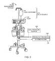
- FIG. 2is a schematic perspective view of a fluid management system used for distending the uterus and for assisting in electrosurgical tissue cutting and extraction.
- FIG. 3is a cross-sectional view of the shaft of the hysteroscope of FIG. 1 showing various channels therein.
- FIG. 4is a schematic side view of the working end of the electrosurgical tissue-cutting device of FIG. 1 showing an outer sleeve and a reciprocating inner sleeve and an electrode arrangement.
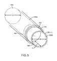
- FIG. 5is a schematic perspective view of the working end of the inner sleeve of FIG. 4 showing its electrode edge.
- FIG. 6Ais a schematic cut-away view of a portion of outer sleeve, inner RF cutting sleeve and a tissue-receiving window of the outer sleeve.
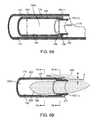
- FIG. 6Bis a schematic view of a distal end portion another embodiment of inner RF cutting sleeve.
- FIG. 7Ais a cross sectional view of the inner RF cutting sleeve of FIG. 6B taken along line 7 A- 7 A of FIG. 6B .
- FIG. 7Bis another cross sectional view of the inner RF cutting sleeve of FIG. 6B taken along line 7 B- 7 B of FIG. 6B .
- FIG. 8is a schematic view of a distal end portion of another embodiment of inner RF cutting sleeve.
- FIG. 9Ais a cross sectional view of the RF cutting sleeve of FIG. 8 taken along line 9 A- 9 A of FIG. 8 .
- FIG. 9Bis a cross sectional view of the RF cutting sleeve of FIG. 8 taken along line 9 B- 9 B of FIG. 8 .
- FIG. 10Ais a perspective view of the working end of the tissue-cutting device of FIG. 1 with the reciprocating RF cutting sleeve in a non-extended position.
- FIG. 10Bis a perspective view of the tissue-cutting device of FIG. 1 with the reciprocating RF cutting sleeve in a partially extended position.
- FIG. 10Cis a perspective view of the tissue-cutting device of FIG. 1 with the reciprocating RF cutting sleeve in a fully extended position across the tissue-receiving window.
- FIG. 11Ais a sectional view of the working end of the tissue-cutting device of FIG. 10A with the reciprocating RF cutting sleeve in a non-extended position.
- FIG. 11Bis a sectional view of the working end of FIG. 10B with the reciprocating RF cutting sleeve in a partially extended position.
- FIG. 11Cis a sectional view of the working end of FIG. 10C with the reciprocating RF cutting sleeve in a fully extended position.
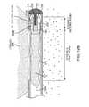
- FIG. 12Ais an enlarged sectional view of the working end of tissue-cutting device of FIG. 11B with the reciprocating RF cutting sleeve in a partially extended position showing the RF field in a first RF mode and plasma cutting of tissue.
- FIG. 12Bis an enlarged sectional view of the working end of FIG. 11C with the reciprocating RF cutting sleeve almost fully extended and showing the RF fields switching to a second RF mode from a first RF mode shown in FIG. 12A .
- FIG. 12Cis an enlarged sectional view of the working end of FIG. 11C with the reciprocating RF cutting sleeve again almost fully extended and showing the explosive vaporization of a captured liquid volume to expel cut tissue in the proximal direction.
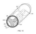
- FIG. 13is an enlarged perspective view of a portion of the working end of FIG. 12C showing an interior chamber and a fluted projecting element.
- FIG. 14is a sectional view of the working end of FIG. 12C showing an interior chamber and a variation of a projecting element.
- FIG. 15is a sectional view of the working end of FIG. 12C showing an interior chamber and a variation of a projecting element configured to explosively vaporize the captured liquid volume.
- FIG. 16Ais a perspective view of an alternative working end with a rotational cutter in a window open position.
- FIG. 16Bis a perspective view of the working end of FIG. 16A with the rotating cutting element in a second position.
- FIG. 16Cis a view of the working end of FIGS. 16A-16B with the rotating cutting element in a third position.
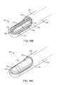
- FIG. 17is an exploded view of the outer sleeve of the working end of FIGS. 16A-16C showing the mating components comprising a ceramic body and a metal tube.
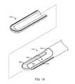
- FIG. 18is a view of the inner sleeve of the working end of FIGS. 16A-16C de-mated from the outer sleeve.
- FIG. 19is an exploded view of the inner sleeve of FIG. 18 showing the mating components comprising a ceramic body and a metal tube.
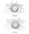
- FIG. 20Ais a cross sectional view of the working end of FIGS. 16A-16C with the rotating inner sleeve in a first position cutting tissue in a first RF mode.
- FIG. 20Bis a cross sectional view of the working end of FIG. 20A with the rotating inner sleeve in a second window-closed position with a second RF mode vaporizing saline captured in the interior extraction channel.
- FIG. 21is a longitudinal sectional view corresponding to the view of FIG. 20B with the rotating inner sleeve in a window-closed position and with the second RF mode vaporizing saline captured in the interior extraction channel to expel tissue proximally.
- FIG. 22is a view of an alternative embodiment of a metal tube component of an inner sleeve.
- FIG. 23is a view of an alternative embodiment of a metal tube component of an inner sleeve.
- FIG. 24is a perspective view of an alternative probe that is configured to stop the inner rotating sleeve in a particular position.
- FIG. 1illustrates an assembly that comprises an endoscope 50 used for hysteroscopy together with a tissue-extraction device 100 extending through a working channel 102 of the endoscope.
- the endoscope or hysteroscope 50has a handle 104 coupled to an elongated shaft 105 having a diameter of 5 mm to 7 mm.
- the working channel 102 thereinmay be round, D-shaped or any other suitable shape.
- the endoscope shaft 105is further configured with an optics channel 106 and one or more fluid inflow/outflow channels 108 a , 108 b ( FIG.
- the fluid inflow source 120is a component of a fluid management system 126 as is known in the art ( FIG. 2 ) which comprises a fluid container 128 and pump mechanism 130 which pumps fluid through the hysteroscope 50 into the uterine cavity.
- the fluid management system 126further includes the negative pressure source 125 (which can comprise an operating room wall suction source) coupled to the tissue-cutting device 100 .
- the handle 104 of the endoscopeincludes the angled extension portion 132 with optics to which a videoscopic camera 135 can be operatively coupled.
- a light source 136also is coupled to light coupling 138 on the handle of the hysteroscope 50 .
- the working channel 102 of the hysteroscopeis configured for insertion and manipulation of the tissue-cutting and extracting device 100 , for example to treat and remove fibroid tissue.
- the hysteroscope shaft 105has an axial length of 21 cm, and can comprise a 0° scope, or 15° to 30° scope.
- the tissue-cutting device 100has a highly elongated shaft assembly 140 configured to extend through the working channel 102 in the hysteroscope.
- a handle 142 of the tissue-cutting device 100is adapted for manipulating the electrosurgical working end 145 of the device. In use, the handle 142 can be manipulated both rotationally and axially, for example, to orient the working end 145 to cut targeted fibroid tissue.
- the tissue-cutting device 100has subsystems coupled to its handle 142 to enable electrosurgical cutting of targeted tissue.
- a radiofrequency generator or RF source 150 and controller 155are coupled to at least one RF electrode carried by the working end 145 as will be described in detail below. In one embodiment shown in FIG.
- an electrical cable 156 and negative pressure source 125are operatively coupled to a connector 158 in handle 142 .
- the electrical cablecouples the RF source 150 to the electrosurgical working end 145 .
- the negative pressure source 125communicates with a tissue-extraction channel 160 in the shaft assembly 140 of the tissue extraction device 100 ( FIG. 4 ).
- FIG. 1further illustrates a seal housing 162 that carries a flexible seal 164 carried by the hysteroscope handle 104 for sealing the shaft 140 of the tissue-cutting device 100 in the working channel 102 to prevent distending fluid from escaping from a uterine cavity.
- the handle 142 of tissue-cutting device 100includes a motor drive 165 for reciprocating or otherwise moving a cutting component of the electrosurgical working end 145 as will be described below.
- the handle 142optionally includes one or more actuator buttons 166 for actuating the device.
- a footswitchcan be used to operate the device.
- the systemincludes a switch or control mechanism to provide a plurality of reciprocation speeds, for example 1 Hz, 2 Hz, 3 Hz, 4 Hz and up to 8 Hz.
- the systemcan include a mechanism for moving and locking the reciprocating cutting sleeve in a non-extended position and in an extended position.
- the systemcan include a mechanism for actuating a single reciprocating stroke.
- an electrosurgical tissue-cutting devicehas an elongate shaft assembly 140 extending about longitudinal axis 168 comprising an exterior or first outer sleeve 170 with passageway or lumen 172 therein that accommodates a second or inner sleeve 175 that can reciprocate (and optionally rotate or oscillate) in lumen 172 to cut tissue as is known in that art of such tubular cutters.
- the tissue-receiving window 176 in the outer sleeve 170has an axial length ranging between 10 mm and 30 mm and extends in a radial angle about outer sleeve 170 from about 45° to 210° relative to axis 168 of the sleeve.
- the outer and inner sleeves 170 and 175can comprise a thin-wall stainless steel material and function as opposing polarity electrodes as will be described in detail below.
- FIGS. 6A-8illustrate insulative layers carried by the outer and inner sleeves 170 and 175 to limit, control and/or prevent unwanted electrical current flows between certain portions of the sleeve.
- a stainless steel outer sleeve 170has an O.D. of 0.143′′ with an I.D. of 0.133′′ and with an inner insulative layer (described below) the sleeve has a nominal I.D. of 0.125′′.
- the stainless steel inner sleeve 175has an O.D. of 0.120′′ with an I.D. of 0.112′′.
- the inner sleeve 175 with an outer insulative layerhas a nominal O.D. of about 0.123′′ to 0.124′′ to reciprocate in lumen 172 .
- outer and or inner sleevescan be fabricated of metal, plastic, ceramic of a combination thereof.
- the cross-section of the sleevescan be round, oval or any other suitable shape.
- the distal end 177 of inner sleeve 175comprises a first polarity electrode with distal cutting electrode edge 180 about which plasma can be generated.
- the electrode edge 180also can be described as an active electrode during tissue cutting since the electrode edge 180 then has a substantially smaller surface area than the opposing polarity or return electrode.
- the exposed surfaces of outer sleeve 170comprises the second polarity electrode 185 , which thus can be described as the return electrode since during use such an electrode surface has a substantially larger surface area compared to the functionally exposed surface area of the active electrode edge 180 .
- the inner sleeve or cutting sleeve 175has an interior tissue extraction lumen 160 with first and second interior diameters that are adapted to electrosurgically cut tissue volumes rapidly—and thereafter consistently extract the cut tissue strips through the highly elongated lumen 160 without clogging.
- the inner sleeve 175has a first diameter portion 190 A that extends from the handle 142 ( FIG. 1 ) to a distal region 192 of the sleeve 175 wherein the tissue extraction lumen transitions to a smaller second diameter lumen 190 B with a reduced diameter indicated at B which is defined by the electrode sleeve element 195 that provides cutting electrode edge 180 .
- the axial length C of the reduced cross-section lumen 190 Bcan range from about 2 mm to 20 mm.
- the first diameter Ais 0.112′′ and the second reduced diameter B is 0.100′′.
- the inner sleeve 175can be an electrically conductive stainless steel and the reduced diameter electrode portion also can comprise a stainless steel electrode sleeve element 195 that is welded in place by weld 196 ( FIG. 6A ).
- the electrode and reduced diameter electrode sleeve element 195comprises a tungsten tube that can be press fit into the distal end 198 of inner sleeve 175 .
- FIG. 5 and 6Afurther illustrates the interfacing insulation layers 202 and 204 carried by the first and second sleeves 170 , 175 , respectively.
- the outer sleeve 170is lined with a thin-wall insulative material 200 , such as PFA, or another material described below.
- the inner sleeve 175has an exterior insulative layer 202 .
- These coating materialscan be lubricious as well as electrically insulative to reduce friction during reciprocation of the inner sleeve 175 .
- the insulative layers 200 and 202 described abovecan comprise a lubricious, hydrophobic or hydrophilic polymeric material.
- the materialcan comprise a bio-compatible material such as PFA, TEFLON®, polytetrafluroethylene (PTFE), FEP (Fluorinated ethylenepropylene), polyethylene, polyamide, ECTFE (Ethylenechlorotrifluoroethylene), ETFE, PVDF, polyvinyl chloride or silicone.
- FIG. 6Banother variation of inner sleeve 175 is illustrated in a schematic view together with a tissue volume being resected with the plasma electrode edge 180 .
- the RF sourceoperates at selected operational parameters to create a plasma around the electrode edge 180 of electrode sleeve 195 as is known in the art.
- the plasma generated at electrode edge 180can cut and ablate a path P in the tissue 220 , and is suited for cutting fibroid tissue and other abnormal uterine tissue.
- the distal portion of the cutting sleeve 175includes a ceramic collar 222 which is adjacent the distal edge 180 of the electrode sleeve 195 .
- the ceramic 222 collarfunctions to confine plasma formation about the distal electrode edge 180 and functions further to prevent plasma from contacting and damaging the polymer insulative layer 202 on the cutting sleeve 175 during operation.
- the path P cut in the tissue 220 with the plasma at electrode edge 180provides a path P having an ablated width indicated at W, wherein such path width W is substantially wide due to tissue vaporization.
- This removal and vaporization of tissue in path Pis substantially different than the effect of cutting similar tissue with a sharp blade edge, as in various prior art devices.
- a sharp blade edgecan divide tissue (without cauterization) but applies mechanical force to the tissue and may prevent a large cross section slug of tissue from being cut.
- the plasma at the electrode edge 180can vaporize a path P in tissue without applying any substantial force on the tissue to thus cut larger cross sections of slugs or strips of tissue.
- the plasma cutting effectreduces the cross section of tissue strip 225 received in the reduced cross-section region 190 B of tissue-extraction lumen 160 .
- FIG. 6Bdepicts a tissue strip 225 entering the reduced cross-section region 190 B, wherein the tissue strip 225 has a smaller cross-section than the lumen due to the vaporization of tissue.
- the cross section of tissue 225 as it enters the larger cross-section lumen 190 Aresults in even greater free space 196 around the tissue strip 225 .
- the resection of tissue with the plasma electrode edge 180together with the lumen transition from the smaller cross-section ( 190 B) to the larger cross-section ( 190 A) of the tissue-extraction lumen 160 can significantly reduce or eliminate the potential for successive resected tissue strips 225 to clog the lumen.
- Prior art resection devices with such small diameter tissue-extraction lumentypically have problems with tissue clogging.
- the negative pressure source 225 coupled to the proximal end of tissue-extraction lumen 160also assists in aspirating and moving tissue strips 225 in the proximal direction to a collection reservoir (not shown) outside the handle 142 of the device.
- FIGS. 7A-7Billustrate the change in lumen diameter of cutting sleeve 175 of FIG. 6B .
- FIG. 8illustrates the distal end of a variation of cutting sleeve 175 ′ which is configured with an electrode cutting element 195 ′ that is partially tubular in contrast to the previously described tubular electrode element 195 ( FIGS. 5 and 6A ).
- FIGS. 9A-9Bagain illustrate the change in cross-section of the tissue-extraction lumen between reduced cross-section region 190 B′ and the increased cross-section region 190 A′ of the cutting sleeve 175 ′ of FIG. 8 .
- the functionalityremains the same whether the cutting electrode element 195 ′ is tubular or partly tubular.
- FIG. 8illustrates the distal end of a variation of cutting sleeve 175 ′ which is configured with an electrode cutting element 195 ′ that is partially tubular in contrast to the previously described tubular electrode element 195 ( FIGS. 5 and 6A ).
- the ceramic collar 222 ′is shown, in one variation, as extending only partially around sleeve 175 ′ to cooperate with the radial angle of cutting electrode element 195 ′. Further, the variation of FIG. 8 illustrates that the ceramic collar 222 ′ has a larger outside diameter than insulative layer 202 . Thus, friction may be reduced since the short axial length of the ceramic collar 222 ′ interfaces and slides against the interfacing insulative layer 200 about the inner surface of lumen 172 of outer sleeve 170 .
- one aspect of the inventioncomprises a tissue cutting and extracting device ( FIGS. 10A-11C ) that includes first and second concentric sleeves having an axis and wherein the second (inner) sleeve 175 has an axially-extending tissue-extraction lumen therein, and wherein the second sleeve 175 is moveable between axially non-extended and extended positions relative to a tissue-receiving window 176 in first sleeve 170 to resect tissue, and wherein the tissue extraction lumen 160 has first and second cross-sections.
- the second sleeve 175has a distal end configured as a plasma electrode edge 180 to resect tissue disposed in tissue-receiving window 176 of the first sleeve 170 . Further, the distal end of the second sleeve, and more particularly, the electrode edge 180 is configured for plasma ablation of a substantially wide path in the tissue.
- the tissue-extraction deviceis configured with a tissue extraction lumen 160 having a distal end portion with a reduced cross-section that is smaller than a cross-section of medial and proximal portions of the lumen 160 .
- the tissue-extraction lumen 160has a reduced cross-sectional area in lumen region 190 B proximate the plasma cutting tip or electrode edge 180 wherein said reduced cross section is less than 95%, 90%, 85% or 80% of the cross sectional area of medial and proximal portions 190 A of the tissue-extraction lumen, and wherein the axial length of the tissue-extraction lumen is at least 10 cm, 20 cm, 30 cm or 40 cm.
- the shaft assembly 140 of the tissue-cutting deviceis 35 cm in length.
- FIGS. 10A-10Cillustrate the working end 145 of the tissue-cutting device 100 with the reciprocating cutting sleeve or inner sleeve 175 in three different axial positions relative to the tissue receiving window 176 in outer sleeve 170 .
- the cutting sleeve 175is shown in a retracted or non-extended position in which the sleeve 175 is at it proximal limit of motion and is prepared to advance distally to an extended position to thereby electrosurgically cut tissue positioned in and/or suctioned into window 176 .
- FIG. 10Bshows the cutting sleeve 175 moved and advanced distally to a partially advanced or medial position relative to tissue cutting window 176 .
- 10Cillustrates the cutting sleeve 175 fully advanced and extended to the distal limit of its motion wherein the plasma cutting electrode 180 has extended past the distal end 226 of tissue-receiving window 176 at which moment the resected tissue strip 225 in excised from tissue volume 220 and captured in reduced cross-sectional lumen region 190 B.
- tissue displacementmechanisms provided by multiple elements and processes to “displace” and move tissue strips 225 ( FIG. 12A ) in the proximal direction in lumen 160 of cutting sleeve 175 to thus ensure that tissue does not clog the lumen of the inner sleeve 175 .
- tissue displacement mechanismcomprises a projecting element 230 that extends proximally from distal tip 232 which is fixedly attached to outer sleeve 170 .
- the projecting element 230extends proximally along central axis 168 in a distal chamber 240 defined by outer sleeve 170 and distal tip 232 .
- the shaft-like projecting element 230in a first functional aspect, comprises a mechanical pusher that functions to push a captured tissue strip 225 proximally from the small cross-section lumen 190 B of cutting sleeve 175 ( FIG. 12A ) as the cutting sleeve 175 moves to its fully advanced or extended position.
- the chamber 240 in the distal end of sleeve 170is configured to capture a volume of saline distending fluid 244 ( FIG. 12A ) from the working space, and wherein the existing RF electrodes of the working end 145 are further configured to explosively vaporize the captured fluid 244 to generate proximally-directed forces on tissue strips 225 resected and disposed in lumen 160 of the cutting sleeve 175 ( FIGS. 12B and 12C ).
- tissue displacement mechanismscan apply a substantial mechanical force on the captured tissue strips 225 by means of the explosive vaporization of liquid in chamber 240 and can function to move tissue strips 225 in the proximal direction in the tissue-extraction lumen 160 . It has been found that using the combination of multiple functional elements and processes can virtually eliminate the potential for tissue clogging the tissue extraction lumen 160 .
- FIGS. 12A-12Cillustrate the functional aspects of the tissue displacement mechanisms and the subsequent explosive vaporization of fluid captured in chamber 240 .
- the reciprocating cutting sleeve 175is shown in a medial position advancing distally wherein plasma at the cutting electrode edge 180 is cutting a tissue strip 225 that is disposed within lumen 160 of the cutting sleeve 175 .
- FIG. 12A-12Cit can be seen that the system operates in first and second electrosurgical modes corresponding to the reciprocation and axial range of motion of cutting sleeve 175 relative to the tissue-receiving window 176 .
- the term “electrosurgical mode”refers to which electrode of the two opposing polarity electrodes functions as an “active electrode” and which electrode functions as a “return electrode”.
- active electrodeand “return electrode” are used in accordance with convention in the art—wherein an active electrode has a smaller surface area than the return electrode which thus focuses RF energy density about such an active electrode.
- the cutting electrode element 195 and its cutting electrode edge 180must comprise the active electrode to focus energy about the electrode to generate the plasma for tissue cutting. Such a high-intensity, energetic plasma at the electrode edge 180 is needed throughout stroke X indicated in FIG. 12A-12B to cut tissue.
- the first modeoccurs over an axial length of travel of inner cutting sleeve 175 as it crosses the tissue-receiving window 176 , at which time the entire exterior surface of outer sleeve 170 comprises the return electrode indicated at 185 .
- the electrical fields EF of the first RF modeare indicated generally in FIG. 12A .
- FIG. 12 Billustrates the moment in time at which the distal advancement or extension of inner cutting sleeve 175 entirely crosses the tissue-receiving window 176 ( FIG. 12A ).
- the electrode sleeve 195 and its electrode edge 180are confined within the mostly insulated-wall chamber 240 defined by the outer sleeve 170 and distal tip 232 .
- the systemis configured to switch to the second RF mode in which the electric fields EF switch from those described previously in the first RF mode.
- the limited interior surface area 250FIG.
- FIG. 12Cillustrates such explosive or expansive vaporization of the distention fluid 244 captured in chamber 240 and further shows the tissue strip 225 being expelled in the proximal direction the lumen 160 of inner cutting sleeve 175 .
- FIG. 14shows the relative surface areas of the active and return electrodes at the extended range of motion of the cutting sleeve 175 , again illustrating that the surface area of the non-insulated distal end surface 250 is small compared to surface 255 of electrode sleeve which comprises the return electrode.
- a single power setting on the RF source 150 and controller 155can be configured both (i) to create plasma at the electrode cutting edge 180 of electrode sleeve 195 to cut tissue in the first mode, and (ii) to explosively vaporize the captured distention fluid 244 in the second mode.
- the systemcan function with RF mode-switching automatically at suitable reciprocation rates ranging from 0.5 cycles per second to 8 or 10 cycles per second.
- the tissue-cutting device described abovecan cut and extract tissue at the rate of from 4 grams/min to 8 grams/min without any potential for tissue strips 225 clogging the tissue-extraction lumen 160 .
- the negative pressure source 125also is coupled to the tissue-extraction lumen 160 to assist in applying forces for tissue extraction.
- the fluid-capture chamber 240 defined by sleeve 170 and distal tip 232can be designed to have a selected volume, exposed electrode surface area, length and geometry to optimize the application of expelling forces to resected tissue strips 225 .
- the diameter of the chamberis 3.175 mm and the length is 5.0 mm which taking into account the projecting element 230 , provided a captured fluid volume of approximately 0.040 mL.
- the captured fluid volumecan range from 0.004 mL to 0.080 mL.
- a chamber 240 with a captured liquid volume of 0.040 mL together with 100% conversion efficiency in and instantaneous vaporizationwould require 103 Joules to heat the liquid from room temperature to water vapor.
- the power requiredwould be on the order of 311 W for full, instantaneous conversion to water vapor.
- a corresponding theoretical expansion of 1700 ⁇would occur in the phase transition, which would results in up to 25,000 psi instantaneously (14.7 psi ⁇ 1700), although due to losses in efficiency and non-instantaneous expansion, the actual pressures would be much less. In any event, the pressures are substantial and can apply significant expelling forces to the captured tissue strips 225 .
- the interior chamber 240can have an axial length from about 0.5 mm to 10 mm to capture a liquid volume ranging from about 0.004 mL 0.01 mL. It can be understood in FIG. 12A , that the interior wall of chamber 240 has an insulator layer 200 which thus limits the electrode surface area 250 exposed to chamber 240 .
- the distal tip 232is stainless steel and is welded to outer sleeve 170 .
- the post element 248is welded to tip 232 or machined as a feature thereof.
- the projecting element 230 in this embodimentis a non-conductive ceramic.
- FIG. 13shows the cross-section of the ceramic projecting element 230 which may be fluted, and which in one embodiment has three flute elements 260 and three corresponding axial grooves 262 in its surface. Any number of flutes, channels or the like is possible, for example from two to about 20.
- the fluted designincreases the available cross-sectional area at the proximal end of the projecting element 230 to push the tissue strip 225 , while at the same time the three grooves 262 permit the proximally-directed jetting of water vapor to impact the tissue exposed to the grooves 262 .
- the axial length DFIG.
- the volume of the chamber 240is configured to capture liquid that when explosively vaporized provides a gas (water vapor) volume sufficient to expand into and occupy at least the volume defined by a 10% of the total length of extraction channel 160 in the device, usually at least 20% of the extraction channel 160 , often at least 40% of the extraction channel 160 , sometimes at least 60% of the extraction channel 160 , other times at least 80% of the extraction channel 160 , and sometimes at least 100% of the extraction channel 160 .
- the distending fluid 244 in the working spacereplenishes the captured fluid in chamber 240 as the cutting sleeve 175 moves in the proximal direction or towards its non-extended position.
- the interior chamber 240is filled with fluid 244 which is then again contained and is then available for explosive vaporization as described above when the cutting sleeve 175 closes the tissue-receiving window 176 .
- a one-way valvecan be provided in the distal tip 232 to draw fluid directly into interior chamber 240 without the need for fluid to migrate through window 176 .
- FIG. 15illustrates another variation in which the active electrode surface area 250 ′ in the second mode comprises a projecting element 230 with conductive regions and non-conductive regions 260 which can have the effect of distributing the focused RF energy delivery over a plurality of discrete regions each in contact with the captured fluid 244 .
- This configurationcan more efficiently vaporize the captured fluid volume in chamber 240 .
- the conductive regions 250 ′can comprise metal discs or washers on post 248 .
- the conductive regions 250 ′can comprise holes, ports or pores in a ceramic material 260 fixed over an electrically conductive post 248 .
- the RF source 150 and controller 155can be programmed to modulate energy delivery parameters during stroke X and stroke Y in FIGS. 12A-12C to provide the optimal energy (i) for plasma cutting with electrode edge 180 , and (ii) for explosively vaporizing the captured fluid in chamber 240 .
- FIGS. 16A-16Cillustrate another embodiment RF cutting probe 700 with working end 702 comprising a tubular cutter adapted for electrosurgical cutting and extracting targeted tissue from the interior of a patient's body.
- the inner cutting sleeveis configured to rotate instead of reciprocate as in the previously-described embodiments.
- the outer sleeve 705comprises a metal tubular member 708 that extends from a handle (not shown) to a working end 702 that again carries a distal dielectric body 710 defining a window 712 therein.
- the inner second sleeve or cutting sleeve 715comprises a metal tubular member 718 that carries a distal dielectric body 720 with a windowed side 724 that is adapted to cooperate with window 712 in the outer sleeve 705 .
- FIGS. 16B-16Cshow the working end 702 of probe 700 with the rotating cutting sleeve 715 and RF electrode edge 725 in two different rotational positions with respect to outer sleeve 705 and window 712 .
- the inner sleeve 715is rotated approximately 90° relative to the outer sleeve 705 .
- the inner sleeve 715is rotated 180° to a position relative to inner sleeve 715 to effectively close the window 712 defined by the outer sleeve 705 . It can easily be understood how rotation of electrode edge 725 thus can cut tissue during rotation and capture the tissue in the window-closed position within the tissue-receiving lumen 730 of the probe.
- the RF electrode edge 725 of the inner sleeve 715comprises a first polarity electrode.
- the exterior surface 732 of the outer sleeve 705comprises a second polarity electrode as described in previous embodiments.
- the distal ends of the inner and outer sleevescomprise ceramic bodies 710 and 720 with an interface 740 therebetween. In other words, the ceramic bodies 710 and 720 rotate about interface 740 and the bodies provide exact electrode spacing ES between the first and second polarity electrodes 725 and 732 .
- the outer sleeve 705comprises as an assembly between the tubular metal sleeve 708 and the dielectric body 710 , which in this variation can be a ceramic such as zirconium.
- the ceramic body 710has a thin wall 742 which can range in thickness from about 0.003′′ and 0.010′′ wherein the ceramic extends 360° around window 712 . Ceramic body 710 can thus be slidably inserted into and bonded to bore 728 in metal sleeve 708 .
- FIG. 18shows the distal end of inner sleeve 715 de-mated from the outer sleeve assembly 705 (see FIG. 16A ).
- the tubular metal sleeve 718 of FIG. 18is fabricated to allow insertion of the ceramic body 720 which supports the electrode edge 725 and provides a rotational bearing surface about the interface 740 (see FIG. 16A ).
- FIG. 19shows an exploded view of the inner sleeve assembly of FIG. 18 .
- ceramic body 720has a hemispherical cross-sectional shape and includes an elongated slots 744 for receiving and supporting an electrode edge 725 .
- FIG. 19shows an exploded view of the inner sleeve assembly of FIG. 18 .
- ceramic body 720has a hemispherical cross-sectional shape and includes an elongated slots 744 for receiving and supporting an electrode edge 725 .
- FIG. 19further shows metal sleeve 718 without ceramic body 720 wherein the electrode edge 725 is cut from a rounded end sleeve 718 .
- the slot 744can receive ceramic body 720 and thus the electrode edge 725 extends in a loop and under rotation will have a leading edge 745 and a trailing edge 745 ′ depending on the direction of rotation.
- leading edgerefers to the electrode edge 725 extending around the distal end of the sleeve 715 to its centerline on its rotational axis.
- the tissue cutting probe 700comprises an outer sleeve 705 and an inner sleeve 715 that is rotatable to provide window-open and window-closed positions and wherein the distal ends of the first and second sleeves 705 , 715 include ceramic bodies 710 , 720 that provide surfaces on either side of a rotational interface 740 . Further, the first and second sleeves provide ceramic bodies 710 , 720 that contact one another on either side of the rotational interface 740 and thus provide a predetermined electrode spacing ES ( FIG. 16A ).
- the wall thickness of the ceramic body 710is from 0.003′′ to 0.004′′. Likewise, the wall thickness of ceramic body 720 can be from 0.003′′ to 0.004′′.
- the radial dimension between the first and second polarity electrodes at a minimum in this variationis 0.006′′.
- the inner sleeve 715carries an outer polymeric dielectric layer which can be 0.001′′ in thickness to thus provide an electrode spacing dimension ES of 0.004′′.
- the dimension between the first and second polarity electrodescan range up to 0.030′′.
- the scope of the inventionincludes providing a rotational tubular cutter with bi-polar electrodes spaced apart between 0.004′′ inches and 0.030′′ inches wherein the cutting sleeve 715 rotates about an interface 740 having dielectric materials on either side thereof.
- the length of the windowcan range from about 5 mm to 30 mm.
- the diameter of the probe working endcan range from about 3 mm to 6 mm or more.
- the rotational speed of the inner sleevecan range from 100 rpm to 5,000 rpm. In one embodiment, a rotation ranging from about 200 rpm to 500 rpm cut tissue efficiently and allowed for effective tissue extraction as described below.
- an opening 748is provided in ceramic body 710 which provides exposure through the ceramic body 710 to metal sleeve 708 which comprises the first polarity electrode when assembled.
- the metal sleeveprovides an interior electrode surface 750 that is exposed to interior chamber 730 .
- the working end 702can function in two RF modes as described in the previous reciprocating probe embodiments (see FIGS. 12A-12C ).
- the exterior surface 732 of outer sleeve 705functions as a first polarity electrode in the interval when the inner sleeve 715 and its second polarity electrode edge 725 rotates from the window-open position of FIG. 16A toward the window-closed position of FIG. 16B .
- FIG. 20Adepicts this interval of rotation, wherein it can be seen that the first RF mode operates for approximately 180° of rotation of the inner cutting sleeve 715 . In this position depicted in FIG.
- leading edge 745 and trailing edge 745 ′ of electrode edge 725are exposed to the open window 712 and electric fields EF extend to the first polarity electrode surface 732 about the exterior of the probe and plasma is formed at leading edge 745 to cut tissue.
- the second RF modeis shown in FIG. 20B , wherein the inner sleeve 715 rotates to the window-closed position and the probe switches instantly to such a second RF mode since the electrode edge 725 is exposed only to the tissue-receiving lumen 730 . It can be understood that the second RF mode operates only when the window 712 is closed as in FIGS. 16C and 20B which causes the instant explosive vaporization of captured saline in the lumen 730 . In FIG.
- the electrode edge 725is exposed only to the interior of lumen 730 and electric fields EF extend between the leading and trailing electrode edges ( 745 and 745 ′) to the exposed electrode surface 750 to thus cause the explosive vaporization of captured saline.
- the vaporizationoccurs instantly within limited degrees of rotation of the inner sleeve, e.g., 5° to 20° of rotation, upon closing the window 712 to thereby expel the resected tissue in the proximal direction as described previously.
- saline captured in the interior channel 730can be distal to the resected tissue or adjacent to the resected tissue in the lumen and the fluid expansion in the liquid-to-vapor transition will instantly expel the resected tissue outwardly or proximally in lumen 730 .
- FIG. 21is a longitudinal sectional view of the working end 702 corresponding to FIG. 20B wherein the electrical fields EF are confined within the interior lumen 730 to thus cause the explosive vaporization of captured saline.
- the second RF mode and the vaporization of captured saline 754 as depicted in FIG. 20Bwill expel the resected tissue 755 proximally within the tissue extraction channel 730 that extends proximally through the probe to a collection reservoir as described in previous embodiments.
- a method of the inventionincludes capturing a tissue volume in a closed distal portion of an interior passageway of an elongate probe and causing a phase transition in a fluid proximate to the captured tissue volume to expand the fluid to apply a proximally directed expelling force to the tissue volume.
- the time interval for providing a closed window to capture the tissue and for causing the explosive vaporizationcan range from about 0.01 second to 2 seconds.
- a negative pressure sourcealso can be coupled to the proximal end of the extraction lumen as described previously.
- the leading edge 745 and the trailing edge 745 ′ of electrode edge 725are provided with different electrical characteristics.
- the leading edge 745is a highly conductive material suited for plasma ignition as described previously.
- the trailing edge 745 ′comprises a different material which is less suited for plasma formation, or entirely not suited for plasma formation.
- the trailing edge 745 ′comprises a resistive material (e.g., a resistive surface coating) wherein RF current ignites plasma about the leading edge 745 but only resistively heats the trailing 745 ′ edge to thus provide enhanced coagulation functionality.
- leading edge 745cuts and the trailing edge 745 ′ is adapted to coagulate the just-cut tissue.
- the trailing edge 745 ′can be configured with a capacitive coating which again can be used for enhancing tissue coagulation.
- the trailing edge 745 ′can comprise a positive temperature coefficient of resistance (PTCR) material for coagulation functionality and further for preventing tissue sticking.
- the trailing edge 745 ′can have a dielectric coating that prevents heating altogether so that the leading edge 745 cut tissues and the trailing edge 745 ′ has no electrosurgical functionality.
- PTCRpositive temperature coefficient of resistance
- FIG. 23illustrates another embodiment of inner sleeve component 718 ′ in which the electrode edge 725 has a leading edge 745 with edge features for causing a variable plasma effect.
- the projecting edges 760 of the leading edge 745 electrodewill create higher energy density plasma than the scalloped or recessed portions 762 which can result in more efficient tissue cutting.
- the electrode surface area of the leading edge 745 and trailing edge 745 ′can differ, again for optimizing the leading edge 745 for plasma cutting and the trailing edge 745 ′ for coagulation.
- the trailing edge 745 ′can be configured for volumetric removal of tissue by plasma abrasion of the just-cut surface since it wiped across the tissue surface.
- leading edge 745 and trailing edge 745 ′can be dissimilar with each edge optimized for a different effect on tissue.
- FIG. 24illustrates another aspect of the invention that can be adapted for selective cutting or coagulating of targeted tissue.
- a rotation control mechanismis provided to which can move the inner sleeve 715 to provide the leading edge 745 in an exposed position and further lock the leading edge 745 in such an exposed position.
- the physiciancan activate the RF source and controller to ignite plasma along the exposed leading edge 745 and thereafter the physician can use the working end as a plasma knife to cut tissue.
- the physiciancan activate the RF source and controller to provide different RF parameters configured to coagulate tissue rather than to cut tissue.
- a hand switch or foot switchcan upon actuation move and lock the inner sleeve in the position shown in FIG. 24 and thereafter actuate the RF source to deliver energy to tissue.
- any other energy sourcecan be used and falls within the scope of the invention, such as an ultrasound tranducer, HIFU, a laser or light energy source, a microwave or a resistive heat source.
- the probecan be configured with a lumen in communication with a remote liquid source to deliver fluid to the interior chamber 240 .
Landscapes
- Health & Medical Sciences (AREA)
- Life Sciences & Earth Sciences (AREA)
- Surgery (AREA)
- Engineering & Computer Science (AREA)
- General Health & Medical Sciences (AREA)
- Biomedical Technology (AREA)
- Heart & Thoracic Surgery (AREA)
- Medical Informatics (AREA)
- Molecular Biology (AREA)
- Animal Behavior & Ethology (AREA)
- Nuclear Medicine, Radiotherapy & Molecular Imaging (AREA)
- Public Health (AREA)
- Veterinary Medicine (AREA)
- Physics & Mathematics (AREA)
- Otolaryngology (AREA)
- Plasma & Fusion (AREA)
- Biophysics (AREA)
- Optics & Photonics (AREA)
- Pathology (AREA)
- Radiology & Medical Imaging (AREA)
- Orthopedic Medicine & Surgery (AREA)
- Electromagnetism (AREA)
- Surgical Instruments (AREA)
Abstract
Description
Claims (20)
Priority Applications (4)
| Application Number | Priority Date | Filing Date | Title |
|---|---|---|---|
| US14/249,032US9549754B2 (en) | 2011-06-24 | 2014-04-09 | Tissue extraction devices and methods |
| US15/378,918US10667857B2 (en) | 2011-06-24 | 2016-12-14 | Tissue extraction devices and methods |
| US16/849,212US11324546B2 (en) | 2011-06-24 | 2020-04-15 | Tissue extraction devices and methods |
| US17/717,677US20220233233A1 (en) | 2011-06-24 | 2022-04-11 | Tissue extraction devices and methods |
Applications Claiming Priority (5)
| Application Number | Priority Date | Filing Date | Title |
|---|---|---|---|
| US201161501106P | 2011-06-24 | 2011-06-24 | |
| US201161531985P | 2011-09-07 | 2011-09-07 | |
| US13/277,913US8512326B2 (en) | 2011-06-24 | 2011-10-20 | Tissue extraction devices and methods |
| US13/910,873US8728066B2 (en) | 2011-06-24 | 2013-06-05 | Tissue extraction devices and methods |
| US14/249,032US9549754B2 (en) | 2011-06-24 | 2014-04-09 | Tissue extraction devices and methods |
Related Parent Applications (1)
| Application Number | Title | Priority Date | Filing Date |
|---|---|---|---|
| US13/910,873ContinuationUS8728066B2 (en) | 2011-06-24 | 2013-06-05 | Tissue extraction devices and methods |
Related Child Applications (1)
| Application Number | Title | Priority Date | Filing Date |
|---|---|---|---|
| US15/378,918ContinuationUS10667857B2 (en) | 2011-06-24 | 2016-12-14 | Tissue extraction devices and methods |
Publications (2)
| Publication Number | Publication Date |
|---|---|
| US20140221997A1 US20140221997A1 (en) | 2014-08-07 |
| US9549754B2true US9549754B2 (en) | 2017-01-24 |
Family
ID=47362539
Family Applications (6)
| Application Number | Title | Priority Date | Filing Date |
|---|---|---|---|
| US13/277,913ActiveUS8512326B2 (en) | 2011-04-11 | 2011-10-20 | Tissue extraction devices and methods |
| US13/910,873ActiveUS8728066B2 (en) | 2011-06-24 | 2013-06-05 | Tissue extraction devices and methods |
| US14/249,032Active2032-07-06US9549754B2 (en) | 2011-06-24 | 2014-04-09 | Tissue extraction devices and methods |
| US15/378,918Active2033-08-31US10667857B2 (en) | 2011-06-24 | 2016-12-14 | Tissue extraction devices and methods |
| US16/849,212ActiveUS11324546B2 (en) | 2011-06-24 | 2020-04-15 | Tissue extraction devices and methods |
| US17/717,677PendingUS20220233233A1 (en) | 2011-06-24 | 2022-04-11 | Tissue extraction devices and methods |
Family Applications Before (2)
| Application Number | Title | Priority Date | Filing Date |
|---|---|---|---|
| US13/277,913ActiveUS8512326B2 (en) | 2011-04-11 | 2011-10-20 | Tissue extraction devices and methods |
| US13/910,873ActiveUS8728066B2 (en) | 2011-06-24 | 2013-06-05 | Tissue extraction devices and methods |
Family Applications After (3)
| Application Number | Title | Priority Date | Filing Date |
|---|---|---|---|
| US15/378,918Active2033-08-31US10667857B2 (en) | 2011-06-24 | 2016-12-14 | Tissue extraction devices and methods |
| US16/849,212ActiveUS11324546B2 (en) | 2011-06-24 | 2020-04-15 | Tissue extraction devices and methods |
| US17/717,677PendingUS20220233233A1 (en) | 2011-06-24 | 2022-04-11 | Tissue extraction devices and methods |
Country Status (3)
| Country | Link |
|---|---|
| US (6) | US8512326B2 (en) |
| EP (2) | EP3777726B1 (en) |
| WO (1) | WO2012178120A1 (en) |
Cited By (7)
| Publication number | Priority date | Publication date | Assignee | Title |
|---|---|---|---|---|
| US10178942B2 (en) | 2015-08-27 | 2019-01-15 | Boston Scientific Scimed, Inc. | Fluid management systems and methods |
| WO2019133542A1 (en)* | 2017-12-27 | 2019-07-04 | Aaron Germain | Arthroscopic devices and methods |
| US10537227B2 (en) | 2015-08-27 | 2020-01-21 | Boston Scientific Scimed, Inc. | Medical devices and methods |
| US11457978B2 (en) | 2018-06-18 | 2022-10-04 | Stryker Corporation | Radiofrequency probe and methods of use and manufacture of same |
| US11883626B2 (en) | 2019-06-27 | 2024-01-30 | Boston Scientific Scimed, Inc. | Detection of an endoscope to a fluid management system |
| US11957406B2 (en) | 2015-08-27 | 2024-04-16 | Minerva Surgical, Inc. | Tissue resecting device and methods |
| US12357755B2 (en) | 2020-01-30 | 2025-07-15 | Boston Scientific Scimed, Inc. | Fluid management system and method for controlling intracavity pressure |
Families Citing this family (92)
| Publication number | Priority date | Publication date | Assignee | Title |
|---|---|---|---|---|
| US9028520B2 (en) | 2006-12-22 | 2015-05-12 | The Spectranetics Corporation | Tissue separating systems and methods |
| US8961551B2 (en) | 2006-12-22 | 2015-02-24 | The Spectranetics Corporation | Retractable separating systems and methods |
| US9561066B2 (en) | 2008-10-06 | 2017-02-07 | Virender K. Sharma | Method and apparatus for tissue ablation |
| US10064697B2 (en) | 2008-10-06 | 2018-09-04 | Santa Anna Tech Llc | Vapor based ablation system for treating various indications |
| US10695126B2 (en) | 2008-10-06 | 2020-06-30 | Santa Anna Tech Llc | Catheter with a double balloon structure to generate and apply a heated ablative zone to tissue |
| US9700365B2 (en) | 2008-10-06 | 2017-07-11 | Santa Anna Tech Llc | Method and apparatus for the ablation of gastrointestinal tissue |
| US9561068B2 (en) | 2008-10-06 | 2017-02-07 | Virender K. Sharma | Method and apparatus for tissue ablation |
| US9662163B2 (en) | 2008-10-21 | 2017-05-30 | Hermes Innovations Llc | Endometrial ablation devices and systems |
| US8821486B2 (en) | 2009-11-13 | 2014-09-02 | Hermes Innovations, LLC | Tissue ablation systems and methods |
| US8540708B2 (en) | 2008-10-21 | 2013-09-24 | Hermes Innovations Llc | Endometrial ablation method |
| US11896282B2 (en) | 2009-11-13 | 2024-02-13 | Hermes Innovations Llc | Tissue ablation systems and method |
| US9510897B2 (en) | 2010-11-05 | 2016-12-06 | Hermes Innovations Llc | RF-electrode surface and method of fabrication |
| EP2677961B1 (en) | 2011-02-24 | 2024-12-11 | Eximo Medical Ltd. | Hybrid catheter for vascular intervention |
| US8323280B2 (en) | 2011-03-21 | 2012-12-04 | Arqos Surgical, Inc. | Medical ablation system and method of use |
| US8512326B2 (en) | 2011-06-24 | 2013-08-20 | Arqos Surgical, Inc. | Tissue extraction devices and methods |
| WO2012178119A2 (en) | 2011-06-24 | 2012-12-27 | Arqos Surgical, Inc. | Tissue extraction devices and methods |
| US9233193B2 (en) | 2011-06-29 | 2016-01-12 | Iogyn, Inc. | Surgical fluid management systems and methods |
| US9737362B2 (en) | 2011-07-06 | 2017-08-22 | Boston Scientific Scimed, Inc. | Tissue cutting systems and methods |
| US9439720B2 (en) | 2011-09-01 | 2016-09-13 | Iogyn, Inc. | Tissue extraction devices and methods |
| US9084847B2 (en) | 2011-09-22 | 2015-07-21 | Iogyn, Inc. | Surgical fluid management systems and methods |
| US9204918B2 (en) | 2011-09-28 | 2015-12-08 | RELIGN Corporation | Medical ablation system and method of use |
| US9597149B2 (en) | 2011-11-04 | 2017-03-21 | Iogyn, Inc. | Tissue extraction devices and methods |
| US9247983B2 (en) | 2011-11-14 | 2016-02-02 | Arqos Surgical, Inc. | Medical instrument and method of use |
| US9439677B2 (en) | 2012-01-20 | 2016-09-13 | Iogyn, Inc. | Medical device and methods |
| US9226792B2 (en)* | 2012-06-12 | 2016-01-05 | Medtronic Advanced Energy Llc | Debridement device and method |
| US9413896B2 (en) | 2012-09-14 | 2016-08-09 | The Spectranetics Corporation | Tissue slitting methods and systems |
| US9498244B2 (en) | 2012-10-19 | 2016-11-22 | Iogyn, Inc. | Medical systems and methods |
| EP3964151A3 (en) | 2013-01-17 | 2022-03-30 | Virender K. Sharma | Apparatus for tissue ablation |
| US9883885B2 (en) | 2013-03-13 | 2018-02-06 | The Spectranetics Corporation | System and method of ablative cutting and pulsed vacuum aspiration |
| US10383691B2 (en) | 2013-03-13 | 2019-08-20 | The Spectranetics Corporation | Last catheter with helical internal lumen |
| US9283040B2 (en) | 2013-03-13 | 2016-03-15 | The Spectranetics Corporation | Device and method of ablative cutting with helical tip |
| US9456872B2 (en) | 2013-03-13 | 2016-10-04 | The Spectranetics Corporation | Laser ablation catheter |
| US9291663B2 (en) | 2013-03-13 | 2016-03-22 | The Spectranetics Corporation | Alarm for lead insulation abnormality |
| US10835279B2 (en) | 2013-03-14 | 2020-11-17 | Spectranetics Llc | Distal end supported tissue slitting apparatus |
| US10842532B2 (en) | 2013-03-15 | 2020-11-24 | Spectranetics Llc | Medical device for removing an implanted object |
| US9918737B2 (en) | 2013-03-15 | 2018-03-20 | The Spectranetics Corporation | Medical device for removing an implanted object |
| WO2014151814A1 (en) | 2013-03-15 | 2014-09-25 | The Spectranetics Corporation | Surgical instrument for removing an implanted object |
| US10448999B2 (en) | 2013-03-15 | 2019-10-22 | The Spectranetics Corporation | Surgical instrument for removing an implanted object |
| US9668765B2 (en) | 2013-03-15 | 2017-06-06 | The Spectranetics Corporation | Retractable blade for lead removal device |
| US9980743B2 (en) | 2013-03-15 | 2018-05-29 | The Spectranetics Corporation | Medical device for removing an implanted object using laser cut hypotubes |
| US9901394B2 (en) | 2013-04-04 | 2018-02-27 | Hermes Innovations Llc | Medical ablation system and method of making |
| WO2014168985A1 (en) | 2013-04-08 | 2014-10-16 | Iogyn, Inc | Medical systems and methods |
| US9486233B2 (en) | 2013-04-26 | 2016-11-08 | Iogyn, Inc. | Tissue resecting systems and methods |
| US10004556B2 (en)* | 2013-05-10 | 2018-06-26 | Corinth MedTech, Inc. | Tissue resecting devices and methods |
| US9649125B2 (en) | 2013-10-15 | 2017-05-16 | Hermes Innovations Llc | Laparoscopic device |
| US9943639B2 (en) | 2013-10-28 | 2018-04-17 | Boston Scientific Scimed, Inc. | Fluid management system and methods |
| EP3113701B1 (en) | 2014-03-03 | 2020-07-22 | The Spectranetics Corporation | Multiple configuration surgical cutting device |
| US12053203B2 (en) | 2014-03-03 | 2024-08-06 | Spectranetics, Llc | Multiple configuration surgical cutting device |
| US20170079718A1 (en) | 2014-05-18 | 2017-03-23 | Eximo Medical Ltd. | System for tissue ablation using pulsed laser |
| US10405924B2 (en) | 2014-05-30 | 2019-09-10 | The Spectranetics Corporation | System and method of ablative cutting and vacuum aspiration through primary orifice and auxiliary side port |
| US10492856B2 (en) | 2015-01-26 | 2019-12-03 | Hermes Innovations Llc | Surgical fluid management system and method of use |
| US10376302B2 (en) | 2015-02-18 | 2019-08-13 | Medtronic Xomed, Inc. | Rotating electrical connector for RF energy enabled tissue debridement device |
| AU2016219980B2 (en) | 2015-02-18 | 2020-09-03 | Medtronic Xomed, Inc. | RF energy enabled tissue debridement device |
| US10188456B2 (en) | 2015-02-18 | 2019-01-29 | Medtronic Xomed, Inc. | Electrode assembly for RF energy enabled tissue debridement device |
| USD765243S1 (en) | 2015-02-20 | 2016-08-30 | The Spectranetics Corporation | Medical device handle |
| USD770616S1 (en) | 2015-02-20 | 2016-11-01 | The Spectranetics Corporation | Medical device handle |
| US9681913B2 (en) | 2015-04-21 | 2017-06-20 | RELIGN Corporation | Arthroscopic devices and methods |
| CN107708591B (en) | 2015-04-29 | 2020-09-29 | 席勒斯科技有限公司 | Medical ablation device and method of use |
| US10045809B2 (en)* | 2015-08-05 | 2018-08-14 | Terumo Cardiovascular Systems Corporation | Endoscopic vessel harvester with blunt and active dissection |
| US9585675B1 (en) | 2015-10-23 | 2017-03-07 | RELIGN Corporation | Arthroscopic devices and methods |
| US9603656B1 (en)* | 2015-10-23 | 2017-03-28 | RELIGN Corporation | Arthroscopic devices and methods |
| US10052149B2 (en) | 2016-01-20 | 2018-08-21 | RELIGN Corporation | Arthroscopic devices and methods |
| US10022140B2 (en) | 2016-02-04 | 2018-07-17 | RELIGN Corporation | Arthroscopic devices and methods |
| US20170258519A1 (en) | 2016-03-10 | 2017-09-14 | RELIGN Corporation | Arthroscopic devices and methods |
| US11207119B2 (en) | 2016-03-11 | 2021-12-28 | RELIGN Corporation | Arthroscopic devices and methods |
| US10595889B2 (en) | 2016-04-11 | 2020-03-24 | RELIGN Corporation | Arthroscopic devices and methods |
| US11172953B2 (en) | 2016-04-11 | 2021-11-16 | RELIGN Corporation | Arthroscopic devices and methods |
| CN109561899A (en) | 2016-04-22 | 2019-04-02 | 锐凌公司 | Arthroscope device and method |
| US12364537B2 (en) | 2016-05-02 | 2025-07-22 | Santa Anna Tech Llc | Catheter with a double balloon structure to generate and apply a heated ablative zone to tissue |
| CN109414292A (en) | 2016-05-05 | 2019-03-01 | 爱克斯莫医疗有限公司 | Device and method for cutting off and/or melting unwanted tissue |
| US11331140B2 (en) | 2016-05-19 | 2022-05-17 | Aqua Heart, Inc. | Heated vapor ablation systems and methods for treating cardiac conditions |
| CN107411818B (en)* | 2016-05-23 | 2020-11-03 | 波士顿科学医学有限公司 | Fluidic devices, methods, and systems |
| CN109661209A (en) | 2016-07-01 | 2019-04-19 | 锐凌公司 | Arthroscope device and method |
| US11426231B2 (en)* | 2017-01-11 | 2022-08-30 | RELIGN Corporation | Arthroscopic devices and methods |
| US11065023B2 (en) | 2017-03-17 | 2021-07-20 | RELIGN Corporation | Arthroscopic devices and methods |
| EP3745973A4 (en)* | 2018-01-30 | 2021-10-20 | Corinth Medtech, Inc. | Surgical device and methods |
| GB2570687B (en)* | 2018-02-02 | 2022-09-28 | Gyrus Medical Ltd | Surgical shaving instruments |
| GB2570686B (en)* | 2018-02-02 | 2023-02-01 | Gyrus Medical Ltd | Surgical shaving instruments |
| US11741080B2 (en)* | 2018-02-22 | 2023-08-29 | Flowfinity Wireless, Inc. | Dynamic data editor for data analysis system |
| WO2019209749A1 (en)* | 2018-04-23 | 2019-10-31 | Aaron Germain | Arthroscopic devices and methods |
| EP3801324B1 (en) | 2018-06-01 | 2025-05-28 | Aqua Medical, Inc. | Vapor generation and delivery systems |
| US11554214B2 (en) | 2019-06-26 | 2023-01-17 | Meditrina, Inc. | Fluid management system |
| US12336751B2 (en) | 2019-08-26 | 2025-06-24 | Aulea Medical, Inc. | Surgical device and methods |
| WO2021060157A1 (en)* | 2019-09-25 | 2021-04-01 | オリンパス株式会社 | Electrode with conduit and treatment tool |
| US20220031390A1 (en)* | 2020-07-31 | 2022-02-03 | Medtronic, Inc. | Bipolar tool for separating tissue adhesions or tunneling |
| US20220039640A1 (en) | 2020-08-04 | 2022-02-10 | Corinth MedTech, Inc. | Surgical device and methods |
| US12376904B1 (en) | 2020-09-08 | 2025-08-05 | Angiodynamics, Inc. | Dynamic laser stabilization and calibration system |
| US20220361906A1 (en)* | 2021-05-11 | 2022-11-17 | Csaba Truckai | Surgical system and method of use |
| CN115227385A (en)* | 2022-06-17 | 2022-10-25 | 上海修能医疗器械有限公司 | Radio frequency scalpel and system |
| US12038322B2 (en) | 2022-06-21 | 2024-07-16 | Eximo Medical Ltd. | Devices and methods for testing ablation systems |
| CN115308004B (en)* | 2022-10-12 | 2022-12-23 | 天津云检医学检验所有限公司 | Laser capture microdissection method |
| WO2025073058A1 (en)* | 2023-10-04 | 2025-04-10 | Light Matter Interaction Inc. | Systems, devices and methods for laser-assisted targeted intracorporeal therapy |
Citations (75)
| Publication number | Priority date | Publication date | Assignee | Title |
|---|---|---|---|---|
| US4650462A (en) | 1985-07-29 | 1987-03-17 | Minnesota Mining And Manufacturing Company | Irrigation system |
| US4735603A (en) | 1986-09-10 | 1988-04-05 | James H. Goodson | Laser smoke evacuation system and method |
| US5098375A (en) | 1989-07-11 | 1992-03-24 | Richard Wolf Gmbh | Unit for insufflating and cleaning gas |
| US5106364A (en) | 1989-07-07 | 1992-04-21 | Kabushiki Kaisha Topcon | Surgical cutter |
| US5277696A (en) | 1991-11-19 | 1994-01-11 | Delma Elektro- Und Medizinische Apparatebau Gesellschaft Mbh | Medical high frequency coagulation instrument |
| US5382229A (en) | 1993-09-21 | 1995-01-17 | Abbott Laboratories | Irrigation solution re-circulating system |
| US5437629A (en) | 1994-04-14 | 1995-08-01 | Bei Medical Systems | Fluid delivery system for hysteroscopic endometrial ablation |
| US5643203A (en) | 1991-08-21 | 1997-07-01 | Smith & Nephew Dyonics Inc. | Fluid management system |
| US5669921A (en) | 1994-07-19 | 1997-09-23 | Linvatec Corporation | Endoscopic shaver blade window positioning system |
| US5730752A (en) | 1996-10-29 | 1998-03-24 | Femrx, Inc. | Tubular surgical cutters having aspiration flow control ports |
| US5823990A (en) | 1997-01-16 | 1998-10-20 | Henley; Julian L. | Ultrasonic liposuction handpiece |
| US5830180A (en) | 1996-07-17 | 1998-11-03 | Aquarius Medical Corporation | Fluid management system for arthroscopic surgery |
| US5853392A (en) | 1997-04-03 | 1998-12-29 | Dennis; William G. | Sleeve trocar with penetration indicator |
| GB2327351A (en) | 1997-07-18 | 1999-01-27 | Gyrus Medical Ltd | Electrosurgical instrument |
| US5906615A (en) | 1997-03-31 | 1999-05-25 | Femrx, Inc. | Serpentine ablation/coagulation electrode |
| US5925050A (en) | 1997-08-15 | 1999-07-20 | The University Of Iowa Research Foundation | Self-clearing bone biting instrument |
| US6032673A (en) | 1994-10-13 | 2000-03-07 | Femrx, Inc. | Methods and devices for tissue removal |
| US6109268A (en) | 1995-06-07 | 2000-08-29 | Arthrocare Corporation | Systems and methods for electrosurgical endoscopic sinus surgery |
| USRE36914E (en) | 1992-10-07 | 2000-10-17 | Minntech Corp | Dialysate filter including an asymmetric microporous, hollow fiber membrane incorporating a polyimide |
| US6206014B1 (en) | 1999-03-26 | 2001-03-27 | American Optisurgical Incorporated | Automated system for rinsing a fluid line of a medical system |
| US6245084B1 (en) | 1998-10-20 | 2001-06-12 | Promex, Inc. | System for controlling a motor driven surgical cutting instrument |
| US20020010463A1 (en) | 1995-02-22 | 2002-01-24 | Medtronic, Inc. | Fluid-assisted electrosurgical device |
| US20020072745A1 (en) | 1998-07-13 | 2002-06-13 | Novacept | Apparatuses and methods for interstitial tissue removal |
| US20030009164A1 (en)* | 1995-06-07 | 2003-01-09 | Arthrocare Corporation | Articulated electrosurgical probe |
| US20030060862A1 (en)* | 2001-09-21 | 2003-03-27 | Gyrus Medical Limited | Surgical system and method |
| US6629986B1 (en)* | 1996-06-07 | 2003-10-07 | Scieran Technologies, Inc. | Apparatus and method for performing opthalmic procedures |
| US20030208200A1 (en)* | 2002-05-03 | 2003-11-06 | Palanker Daniel V. | Method and apparatus for plasma-mediated thermo-electrical ablation |
| US20040092980A1 (en) | 2001-10-26 | 2004-05-13 | Cesarini Peter M. | Reciprocating rotary arthroscopic surgical instrument |
| US20040102770A1 (en) | 1997-07-18 | 2004-05-27 | Gyrus Medical Limited | Electrosurgical instrument |
| US20040167428A1 (en) | 2003-02-24 | 2004-08-26 | Senorx, Inc. | Biopsy device with inner cutting member |
| US20040199226A1 (en)* | 2000-12-09 | 2004-10-07 | Shadduck John H. | Thermotherapy device with superlattice cooling |
| US20040267255A1 (en) | 2001-08-15 | 2004-12-30 | Auge Ii Wayne K | Methods and devices for electrosurgery |
| US20050096649A1 (en) | 2003-11-04 | 2005-05-05 | Medtronic, Inc. | Surgical micro-resecting instrument with electrocautery and continuous aspiration features |
| US20050236329A1 (en) | 2004-04-27 | 2005-10-27 | Brotherton John D | Metabolic detoxification and method |
| US20060047185A1 (en) | 2004-08-27 | 2006-03-02 | Cemal Shener | Tissue resecting system |
| US7029451B2 (en) | 2002-11-06 | 2006-04-18 | Rubicor Medical, Inc. | Excisional devices having selective cutting and atraumatic configurations and methods of using same |
| US20060135955A1 (en) | 2003-01-18 | 2006-06-22 | Shadduck John H | Medical instrument and method of use |
| US7070604B1 (en) | 2002-10-07 | 2006-07-04 | Garito Jon C | RF electrosurgically-activated cutter |
| US20060224154A1 (en) | 2001-12-07 | 2006-10-05 | Shadduck John H | Medical instrument and method of use |
| US20070016182A1 (en) | 2003-03-06 | 2007-01-18 | Tissuelink Medical, Inc | Fluid-assisted medical devices, systems and methods |
| US20070021713A1 (en) | 2004-01-19 | 2007-01-25 | Atul Kumar | System for distending body tissue cavities by continuous flow irrigation |
| US20070036768A1 (en) | 2001-12-07 | 2007-02-15 | Fraser John K | Systems and methods for treating patients with processed lipoaspirate cells |
| US7204821B1 (en) | 2000-01-31 | 2007-04-17 | Ethicon, Inc. | Surgical fluid management system with suction control |
| US20070088275A1 (en) | 2003-04-08 | 2007-04-19 | Ralph Stearns | Trocar assembly with pneumatic sealing |
| US7226459B2 (en) | 2001-10-26 | 2007-06-05 | Smith & Nephew, Inc. | Reciprocating rotary arthroscopic surgical instrument |
| US20070244353A1 (en) | 2006-04-13 | 2007-10-18 | Larsen Dane M | Resectoscopic Device And Method |
| US20080039832A1 (en)* | 2002-05-03 | 2008-02-14 | Palanker Daniel V | Method and apparatus for plasma-mediated thermo-electrical ablation |
| US20080065060A1 (en) | 2006-09-07 | 2008-03-13 | Moshe Ein-Gal | Controlled monopolar and bipolar application of RF energy |
| US20080091061A1 (en) | 2006-10-11 | 2008-04-17 | Alka Kumar | Efficient continuous flow irrigation system |
| US20080091071A1 (en) | 2006-10-11 | 2008-04-17 | Alka Kumar | System for evacuating detached tissue in continuous flow irrigation endoscopic procedures |
| US20080103504A1 (en)* | 2006-10-30 | 2008-05-01 | Schmitz Gregory P | Percutaneous spinal stenosis treatment |
| US7384417B2 (en) | 1990-12-14 | 2008-06-10 | Cucin Robert L | Air-powered tissue-aspiration instrument system employing curved bipolar-type electro-cauterizing dual cannula assembly |
| US20080287893A1 (en) | 2005-12-15 | 2008-11-20 | Leonard Ineson | Air suctioning and filtering device having instantly available air suctioning and thermal sensing |
| US20090082715A1 (en) | 2007-09-21 | 2009-03-26 | Charles Steven T | System and Method For Actuation of A Vitreous Cutter |
| US7510535B2 (en)* | 2002-06-06 | 2009-03-31 | Ethicon Endo-Surgery, Inc. | Biopsy method |
| US20090137943A1 (en) | 2006-12-18 | 2009-05-28 | Ralph Stearns | System for surgical insufflation and gas recirculation |
| EP2100567A1 (en) | 2008-03-11 | 2009-09-16 | Tyco Healthcare Group, LP | Bipolar cutting end effector |
| US20090270898A1 (en) | 2007-04-06 | 2009-10-29 | Interlace Medical, Inc. | Tissue removal device with high reciprocation rate |
| US7674259B2 (en) | 2000-12-09 | 2010-03-09 | Tsunami Medtech | Medical instruments and techniques for thermally-mediated therapies |
| US20100100091A1 (en) | 2008-10-21 | 2010-04-22 | Hermes Innovations Llc | Tissue ablation systems |
| US20100145325A1 (en)* | 2008-11-06 | 2010-06-10 | Michael Hoey | Systems and Methods for Treatment of Prostatic Tissue |
| US20100152533A1 (en) | 2008-12-16 | 2010-06-17 | Mark Joseph L | Tissue removal device for use with imaging devices in neurosurgical and spinal surgery applications |
| US20100152724A1 (en)* | 2008-12-12 | 2010-06-17 | Arthrocare Corporation | Systems and methods for limiting joint temperature |
| WO2010096139A2 (en) | 2009-02-20 | 2010-08-26 | Nico Corporation | Tissue removal device for neurosurgical and spinal surgery applications |
| US7892229B2 (en) | 2003-01-18 | 2011-02-22 | Tsunami Medtech, Llc | Medical instruments and techniques for treating pulmonary disorders |
| US20110224486A1 (en) | 2005-06-24 | 2011-09-15 | Mimi Nguyen | Minimally Invasive Surgical Stabilization Devices and Methods |
| US20110306968A1 (en) | 2010-06-10 | 2011-12-15 | Beckman Andrew T | Heat management configurations for controlling heat dissipation from electrosurgical instruments |
| US20120330292A1 (en) | 2011-06-24 | 2012-12-27 | Arqos Surgical, Inc. | Tissue extraction devices and methods |
| US20130046304A1 (en) | 2011-06-24 | 2013-02-21 | Arqos Surgical, Inc. | Tissue extraction devices and methods |
| US20130079702A1 (en) | 2011-09-22 | 2013-03-28 | Arqos Surgical, Inc. | Surgical fluid management systems and methods |
| US20130103021A1 (en) | 2011-04-11 | 2013-04-25 | Arqos Surgical, Inc. | Tissue extraction devices and methods |
| US20130172805A1 (en) | 2011-06-29 | 2013-07-04 | Arqos Surgical, Inc. | Surgical fluid management systems and methods |
| US20130172870A1 (en) | 2011-07-06 | 2013-07-04 | Arqos Surgical, Inc. | Tissue cutting systems and methods |
| US20130231652A1 (en) | 2011-09-01 | 2013-09-05 | Arqos Surgical, Inc. | Tissue extraction devices and methods |
| US20130296847A1 (en) | 2011-11-04 | 2013-11-07 | Arqos Surgical, Inc. | Tissue extraction devices and methods |
Family Cites Families (6)
| Publication number | Priority date | Publication date | Assignee | Title |
|---|---|---|---|---|
| US4945912A (en)* | 1988-11-25 | 1990-08-07 | Sensor Electronics, Inc. | Catheter with radiofrequency heating applicator |
| US5403311A (en)* | 1993-03-29 | 1995-04-04 | Boston Scientific Corporation | Electro-coagulation and ablation and other electrotherapeutic treatments of body tissue |
| US5649547A (en)* | 1994-03-24 | 1997-07-22 | Biopsys Medical, Inc. | Methods and devices for automated biopsy and collection of soft tissue |
| US6312430B1 (en)* | 1996-10-28 | 2001-11-06 | Endoscopic Concepts, Inc. | Bipolar electrosurgical end effectors |
| US7150747B1 (en)* | 2003-01-22 | 2006-12-19 | Smith & Nephew, Inc. | Electrosurgical cutter |
| US8777941B2 (en)* | 2007-05-10 | 2014-07-15 | Covidien Lp | Adjustable impedance electrosurgical electrodes |
- 2011
- 2011-10-20USUS13/277,913patent/US8512326B2/enactiveActive
- 2012
- 2012-06-22EPEP20193493.2Apatent/EP3777726B1/enactiveActive
- 2012-06-22EPEP12803048.3Apatent/EP2723255B1/enactiveActive
- 2012-06-22WOPCT/US2012/043892patent/WO2012178120A1/enunknown
- 2013
- 2013-06-05USUS13/910,873patent/US8728066B2/enactiveActive
- 2014
- 2014-04-09USUS14/249,032patent/US9549754B2/enactiveActive
- 2016
- 2016-12-14USUS15/378,918patent/US10667857B2/enactiveActive
- 2020
- 2020-04-15USUS16/849,212patent/US11324546B2/enactiveActive
- 2022
- 2022-04-11USUS17/717,677patent/US20220233233A1/enactivePending
Patent Citations (88)
| Publication number | Priority date | Publication date | Assignee | Title |
|---|---|---|---|---|
| US4650462A (en) | 1985-07-29 | 1987-03-17 | Minnesota Mining And Manufacturing Company | Irrigation system |
| US4735603A (en) | 1986-09-10 | 1988-04-05 | James H. Goodson | Laser smoke evacuation system and method |
| US5106364A (en) | 1989-07-07 | 1992-04-21 | Kabushiki Kaisha Topcon | Surgical cutter |
| US5098375A (en) | 1989-07-11 | 1992-03-24 | Richard Wolf Gmbh | Unit for insufflating and cleaning gas |
| US7384417B2 (en) | 1990-12-14 | 2008-06-10 | Cucin Robert L | Air-powered tissue-aspiration instrument system employing curved bipolar-type electro-cauterizing dual cannula assembly |
| US5643203A (en) | 1991-08-21 | 1997-07-01 | Smith & Nephew Dyonics Inc. | Fluid management system |
| US5277696A (en) | 1991-11-19 | 1994-01-11 | Delma Elektro- Und Medizinische Apparatebau Gesellschaft Mbh | Medical high frequency coagulation instrument |
| USRE36914E (en) | 1992-10-07 | 2000-10-17 | Minntech Corp | Dialysate filter including an asymmetric microporous, hollow fiber membrane incorporating a polyimide |
| US5382229A (en) | 1993-09-21 | 1995-01-17 | Abbott Laboratories | Irrigation solution re-circulating system |
| US5437629A (en) | 1994-04-14 | 1995-08-01 | Bei Medical Systems | Fluid delivery system for hysteroscopic endometrial ablation |
| US5810858A (en) | 1994-07-19 | 1998-09-22 | Linvatec Corporation | Endoscopic shaver blade window positioning system |
| US5669921A (en) | 1994-07-19 | 1997-09-23 | Linvatec Corporation | Endoscopic shaver blade window positioning system |
| US6032673A (en) | 1994-10-13 | 2000-03-07 | Femrx, Inc. | Methods and devices for tissue removal |
| US20020010463A1 (en) | 1995-02-22 | 2002-01-24 | Medtronic, Inc. | Fluid-assisted electrosurgical device |
| US6109268A (en) | 1995-06-07 | 2000-08-29 | Arthrocare Corporation | Systems and methods for electrosurgical endoscopic sinus surgery |
| US20030009164A1 (en)* | 1995-06-07 | 2003-01-09 | Arthrocare Corporation | Articulated electrosurgical probe |
| US20040049217A1 (en)* | 1996-06-07 | 2004-03-11 | Rod Ross | Apparatus and method for performing ophthalmic procedures |
| US6629986B1 (en)* | 1996-06-07 | 2003-10-07 | Scieran Technologies, Inc. | Apparatus and method for performing opthalmic procedures |
| US5830180A (en) | 1996-07-17 | 1998-11-03 | Aquarius Medical Corporation | Fluid management system for arthroscopic surgery |
| US5730752A (en) | 1996-10-29 | 1998-03-24 | Femrx, Inc. | Tubular surgical cutters having aspiration flow control ports |
| US5823990A (en) | 1997-01-16 | 1998-10-20 | Henley; Julian L. | Ultrasonic liposuction handpiece |
| US5906615A (en) | 1997-03-31 | 1999-05-25 | Femrx, Inc. | Serpentine ablation/coagulation electrode |
| US5853392A (en) | 1997-04-03 | 1998-12-29 | Dennis; William G. | Sleeve trocar with penetration indicator |
| US20040102770A1 (en) | 1997-07-18 | 2004-05-27 | Gyrus Medical Limited | Electrosurgical instrument |
| GB2327351A (en) | 1997-07-18 | 1999-01-27 | Gyrus Medical Ltd | Electrosurgical instrument |
| US5925050A (en) | 1997-08-15 | 1999-07-20 | The University Of Iowa Research Foundation | Self-clearing bone biting instrument |
| US20110264090A1 (en) | 1998-03-27 | 2011-10-27 | Tsunami Medtech, Llc | Medical instruments and techniques for treating pulmonary disorders |
| US20020072745A1 (en) | 1998-07-13 | 2002-06-13 | Novacept | Apparatuses and methods for interstitial tissue removal |
| US6245084B1 (en) | 1998-10-20 | 2001-06-12 | Promex, Inc. | System for controlling a motor driven surgical cutting instrument |
| US6358263B2 (en) | 1998-10-20 | 2002-03-19 | Promex, Inc. | System for controlling a motor driven surgical cutting instrument |
| US6206014B1 (en) | 1999-03-26 | 2001-03-27 | American Optisurgical Incorporated | Automated system for rinsing a fluid line of a medical system |
| US7204821B1 (en) | 2000-01-31 | 2007-04-17 | Ethicon, Inc. | Surgical fluid management system with suction control |
| US20090312753A1 (en) | 2000-12-09 | 2009-12-17 | Tsunami Medtech, Llc | Thermotherapy device |
| US20040199226A1 (en)* | 2000-12-09 | 2004-10-07 | Shadduck John H. | Thermotherapy device with superlattice cooling |
| US7674259B2 (en) | 2000-12-09 | 2010-03-09 | Tsunami Medtech | Medical instruments and techniques for thermally-mediated therapies |
| US7549987B2 (en) | 2000-12-09 | 2009-06-23 | Tsunami Medtech, Llc | Thermotherapy device |
| US20040267255A1 (en) | 2001-08-15 | 2004-12-30 | Auge Ii Wayne K | Methods and devices for electrosurgery |
| US20030060862A1 (en)* | 2001-09-21 | 2003-03-27 | Gyrus Medical Limited | Surgical system and method |
| US20040092980A1 (en) | 2001-10-26 | 2004-05-13 | Cesarini Peter M. | Reciprocating rotary arthroscopic surgical instrument |
| US7226459B2 (en) | 2001-10-26 | 2007-06-05 | Smith & Nephew, Inc. | Reciprocating rotary arthroscopic surgical instrument |
| US20120271300A9 (en) | 2001-12-07 | 2012-10-25 | Shadduck John H | Medical instrument and method of use |
| US20060224154A1 (en) | 2001-12-07 | 2006-10-05 | Shadduck John H | Medical instrument and method of use |
| US20070036768A1 (en) | 2001-12-07 | 2007-02-15 | Fraser John K | Systems and methods for treating patients with processed lipoaspirate cells |
| US20080039832A1 (en)* | 2002-05-03 | 2008-02-14 | Palanker Daniel V | Method and apparatus for plasma-mediated thermo-electrical ablation |
| US20030208200A1 (en)* | 2002-05-03 | 2003-11-06 | Palanker Daniel V. | Method and apparatus for plasma-mediated thermo-electrical ablation |
| US7510535B2 (en)* | 2002-06-06 | 2009-03-31 | Ethicon Endo-Surgery, Inc. | Biopsy method |
| US7070604B1 (en) | 2002-10-07 | 2006-07-04 | Garito Jon C | RF electrosurgically-activated cutter |
| US7029451B2 (en) | 2002-11-06 | 2006-04-18 | Rubicor Medical, Inc. | Excisional devices having selective cutting and atraumatic configurations and methods of using same |
| US20060135955A1 (en) | 2003-01-18 | 2006-06-22 | Shadduck John H | Medical instrument and method of use |
| US7892229B2 (en) | 2003-01-18 | 2011-02-22 | Tsunami Medtech, Llc | Medical instruments and techniques for treating pulmonary disorders |
| US8313485B2 (en) | 2003-01-18 | 2012-11-20 | Tsunami Medtech, Llc | Method for performing lung volume reduction |
| US20040167427A1 (en)* | 2003-02-24 | 2004-08-26 | Senorx, Inc. | Biopsy device with inner cutter |
| US20040167428A1 (en) | 2003-02-24 | 2004-08-26 | Senorx, Inc. | Biopsy device with inner cutting member |
| US20070016182A1 (en) | 2003-03-06 | 2007-01-18 | Tissuelink Medical, Inc | Fluid-assisted medical devices, systems and methods |
| US20070088275A1 (en) | 2003-04-08 | 2007-04-19 | Ralph Stearns | Trocar assembly with pneumatic sealing |
| US20050096649A1 (en) | 2003-11-04 | 2005-05-05 | Medtronic, Inc. | Surgical micro-resecting instrument with electrocautery and continuous aspiration features |
| US20070021713A1 (en) | 2004-01-19 | 2007-01-25 | Atul Kumar | System for distending body tissue cavities by continuous flow irrigation |
| US20050236329A1 (en) | 2004-04-27 | 2005-10-27 | Brotherton John D | Metabolic detoxification and method |
| US20060047185A1 (en) | 2004-08-27 | 2006-03-02 | Cemal Shener | Tissue resecting system |
| US20110224486A1 (en) | 2005-06-24 | 2011-09-15 | Mimi Nguyen | Minimally Invasive Surgical Stabilization Devices and Methods |
| US20080287893A1 (en) | 2005-12-15 | 2008-11-20 | Leonard Ineson | Air suctioning and filtering device having instantly available air suctioning and thermal sensing |
| US20070244353A1 (en) | 2006-04-13 | 2007-10-18 | Larsen Dane M | Resectoscopic Device And Method |
| US20080065060A1 (en) | 2006-09-07 | 2008-03-13 | Moshe Ein-Gal | Controlled monopolar and bipolar application of RF energy |
| US20080091061A1 (en) | 2006-10-11 | 2008-04-17 | Alka Kumar | Efficient continuous flow irrigation system |
| US20080091071A1 (en) | 2006-10-11 | 2008-04-17 | Alka Kumar | System for evacuating detached tissue in continuous flow irrigation endoscopic procedures |
| US20080103504A1 (en)* | 2006-10-30 | 2008-05-01 | Schmitz Gregory P | Percutaneous spinal stenosis treatment |
| US20090137943A1 (en) | 2006-12-18 | 2009-05-28 | Ralph Stearns | System for surgical insufflation and gas recirculation |
| US20090270898A1 (en) | 2007-04-06 | 2009-10-29 | Interlace Medical, Inc. | Tissue removal device with high reciprocation rate |
| US20120053583A1 (en) | 2007-04-06 | 2012-03-01 | The Board Of Trustees Of The Leland Stanford Junior University | Method for plasma-mediated thermo-electrical ablation with low temperature electrode |
| US20090082715A1 (en) | 2007-09-21 | 2009-03-26 | Charles Steven T | System and Method For Actuation of A Vitreous Cutter |
| EP2100567A1 (en) | 2008-03-11 | 2009-09-16 | Tyco Healthcare Group, LP | Bipolar cutting end effector |
| US20100100091A1 (en) | 2008-10-21 | 2010-04-22 | Hermes Innovations Llc | Tissue ablation systems |
| US20100145325A1 (en)* | 2008-11-06 | 2010-06-10 | Michael Hoey | Systems and Methods for Treatment of Prostatic Tissue |
| US20100152724A1 (en)* | 2008-12-12 | 2010-06-17 | Arthrocare Corporation | Systems and methods for limiting joint temperature |
| US20100152533A1 (en) | 2008-12-16 | 2010-06-17 | Mark Joseph L | Tissue removal device for use with imaging devices in neurosurgical and spinal surgery applications |
| WO2010096139A2 (en) | 2009-02-20 | 2010-08-26 | Nico Corporation | Tissue removal device for neurosurgical and spinal surgery applications |
| WO2010096139A3 (en) | 2009-02-20 | 2011-12-01 | Nico Corporation | Tissue removal device for neurosurgical and spinal surgery applications |
| US20110306968A1 (en) | 2010-06-10 | 2011-12-15 | Beckman Andrew T | Heat management configurations for controlling heat dissipation from electrosurgical instruments |
| US20130103021A1 (en) | 2011-04-11 | 2013-04-25 | Arqos Surgical, Inc. | Tissue extraction devices and methods |
| US20120330292A1 (en) | 2011-06-24 | 2012-12-27 | Arqos Surgical, Inc. | Tissue extraction devices and methods |
| US20130046304A1 (en) | 2011-06-24 | 2013-02-21 | Arqos Surgical, Inc. | Tissue extraction devices and methods |
| US8512326B2 (en) | 2011-06-24 | 2013-08-20 | Arqos Surgical, Inc. | Tissue extraction devices and methods |
| US8728066B2 (en) | 2011-06-24 | 2014-05-20 | Arqos Surgical, Inc. | Tissue extraction devices and methods |
| US20130172805A1 (en) | 2011-06-29 | 2013-07-04 | Arqos Surgical, Inc. | Surgical fluid management systems and methods |
| US20130172870A1 (en) | 2011-07-06 | 2013-07-04 | Arqos Surgical, Inc. | Tissue cutting systems and methods |
| US20130231652A1 (en) | 2011-09-01 | 2013-09-05 | Arqos Surgical, Inc. | Tissue extraction devices and methods |
| US20130079702A1 (en) | 2011-09-22 | 2013-03-28 | Arqos Surgical, Inc. | Surgical fluid management systems and methods |
| US20130296847A1 (en) | 2011-11-04 | 2013-11-07 | Arqos Surgical, Inc. | Tissue extraction devices and methods |
Non-Patent Citations (3)
| Title |
|---|
| AAGL Practice Report: Practice Guidelines for the Management of Hysteroscopic Distending Media: (Replaces Hysteroscopic Fluid Monitoring Guidelines. J Am Assoc Gynecol Laparosc. 2000;7: 167-168) J Minim Invasive Gynecol. Mar.-Apr. 2013;20:137-48. doi: 10.1016/j.jmig.2012.12.002. |
| Liu, et al. Clinical application of hysteriscopic electroresection in 775 cases. Di YHi Jun Yi Da Xue Xue Bao. Apr. 2004;24(4):467-9. (in Chinese with English abstract). |
| Phillips, et al. The Effect of Dilute Vasopressin Solution on Blood Loss During Operative Hysteroscopy. J Am Assoc Gynecol Laparosc. Aug. 1996;3(4, Supplement):S38. |
Cited By (11)
| Publication number | Priority date | Publication date | Assignee | Title |
|---|---|---|---|---|
| US10178942B2 (en) | 2015-08-27 | 2019-01-15 | Boston Scientific Scimed, Inc. | Fluid management systems and methods |
| US10349815B2 (en) | 2015-08-27 | 2019-07-16 | Boston Scientific Scimed, Inc. | Fluid management systems and methods |
| US10531785B2 (en) | 2015-08-27 | 2020-01-14 | Boston Scientific Scimed, Inc. | Fluid management systems and methods |
| US10537227B2 (en) | 2015-08-27 | 2020-01-21 | Boston Scientific Scimed, Inc. | Medical devices and methods |
| US11957406B2 (en) | 2015-08-27 | 2024-04-16 | Minerva Surgical, Inc. | Tissue resecting device and methods |
| US12402939B2 (en) | 2015-08-27 | 2025-09-02 | Minerva Surgical, Inc. | Tissue resecting device and methods |
| WO2019133542A1 (en)* | 2017-12-27 | 2019-07-04 | Aaron Germain | Arthroscopic devices and methods |
| US11723681B2 (en) | 2017-12-27 | 2023-08-15 | RELIGN Corporation | Arthroscopic devices and methods |
| US11457978B2 (en) | 2018-06-18 | 2022-10-04 | Stryker Corporation | Radiofrequency probe and methods of use and manufacture of same |
| US11883626B2 (en) | 2019-06-27 | 2024-01-30 | Boston Scientific Scimed, Inc. | Detection of an endoscope to a fluid management system |
| US12357755B2 (en) | 2020-01-30 | 2025-07-15 | Boston Scientific Scimed, Inc. | Fluid management system and method for controlling intracavity pressure |
Also Published As
| Publication number | Publication date |
|---|---|
| US11324546B2 (en) | 2022-05-10 |
| US8728066B2 (en) | 2014-05-20 |
| US20130267937A1 (en) | 2013-10-10 |
| EP3777726A1 (en) | 2021-02-17 |
| US20170086918A1 (en) | 2017-03-30 |
| EP2723255B1 (en) | 2020-10-07 |
| US8512326B2 (en) | 2013-08-20 |
| US10667857B2 (en) | 2020-06-02 |
| US20200281645A1 (en) | 2020-09-10 |
| US20140221997A1 (en) | 2014-08-07 |
| US20220233233A1 (en) | 2022-07-28 |
| EP3777726B1 (en) | 2024-10-30 |
| US20120330292A1 (en) | 2012-12-27 |
| WO2012178120A1 (en) | 2012-12-27 |
| EP2723255A1 (en) | 2014-04-30 |
| EP2723255A4 (en) | 2014-12-24 |
Similar Documents
| Publication | Publication Date | Title |
|---|---|---|
| US11324546B2 (en) | Tissue extraction devices and methods | |
| US11937844B2 (en) | Tissue resecting systems and methods | |
| US11583335B2 (en) | Tissue extraction devices and methods |
Legal Events
| Date | Code | Title | Description |
|---|---|---|---|
| AS | Assignment | Owner name:IOGYN, INC., CALIFORNIA Free format text:ASSIGNMENT OF ASSIGNORS INTEREST;ASSIGNOR:ARQOS SURGICAL, INC.;REEL/FRAME:033182/0220 Effective date:20140505 | |
| FEPP | Fee payment procedure | Free format text:ENTITY STATUS SET TO UNDISCOUNTED (ORIGINAL EVENT CODE: BIG.); ENTITY STATUS OF PATENT OWNER: LARGE ENTITY | |
| FEPP | Fee payment procedure | Free format text:PAYOR NUMBER ASSIGNED (ORIGINAL EVENT CODE: ASPN); ENTITY STATUS OF PATENT OWNER: LARGE ENTITY | |
| STCF | Information on status: patent grant | Free format text:PATENTED CASE | |
| AS | Assignment | Owner name:BOSTON SCIENTIFIC SCIMED, INC., MINNESOTA Free format text:ASSIGNMENT OF ASSIGNORS INTEREST;ASSIGNOR:IOGYN, INC.;REEL/FRAME:042294/0001 Effective date:20141201 | |
| AS | Assignment | Owner name:BOSTON SCIENTIFIC SCIMED, INC., MINNESOTA Free format text:ASSIGNMENT OF ASSIGNORS INTEREST;ASSIGNOR:IOGYN, INC.;REEL/FRAME:042154/0139 Effective date:20141201 | |
| MAFP | Maintenance fee payment | Free format text:PAYMENT OF MAINTENANCE FEE, 4TH YEAR, LARGE ENTITY (ORIGINAL EVENT CODE: M1551); ENTITY STATUS OF PATENT OWNER: LARGE ENTITY Year of fee payment:4 | |
| AS | Assignment | Owner name:MINERVA SURGICAL, INC., CALIFORNIA Free format text:ASSIGNMENT OF ASSIGNORS INTEREST;ASSIGNOR:BOSTON SCIENTIFIC SCIMED, INC.;REEL/FRAME:053265/0675 Effective date:20200429 | |
| AS | Assignment | Owner name:CANADIAN IMPERIAL BANK OF COMMERCE, CANADA Free format text:SECURITY INTEREST;ASSIGNOR:MINERVA SURGICAL, INC.;REEL/FRAME:057758/0137 Effective date:20211008 | |
| MAFP | Maintenance fee payment | Free format text:PAYMENT OF MAINTENANCE FEE, 8TH YEAR, LARGE ENTITY (ORIGINAL EVENT CODE: M1552); ENTITY STATUS OF PATENT OWNER: LARGE ENTITY Year of fee payment:8 |