US9549739B2 - Devices, systems and methods for treating benign prostatic hyperplasia and other conditions - Google Patents
Devices, systems and methods for treating benign prostatic hyperplasia and other conditionsDownload PDFInfo
- Publication number
- US9549739B2 US9549739B2US13/831,021US201313831021AUS9549739B2US 9549739 B2US9549739 B2US 9549739B2US 201313831021 AUS201313831021 AUS 201313831021AUS 9549739 B2US9549739 B2US 9549739B2
- Authority
- US
- United States
- Prior art keywords
- anchor
- tissue
- distal
- prostate gland
- lumen
- Prior art date
- Legal status (The legal status is an assumption and is not a legal conclusion. Google has not performed a legal analysis and makes no representation as to the accuracy of the status listed.)
- Expired - Lifetime, expires
Links
Images


Classifications
- A—HUMAN NECESSITIES
- A61—MEDICAL OR VETERINARY SCIENCE; HYGIENE
- A61B—DIAGNOSIS; SURGERY; IDENTIFICATION
- A61B17/00—Surgical instruments, devices or methods
- A61B17/12—Surgical instruments, devices or methods for ligaturing or otherwise compressing tubular parts of the body, e.g. blood vessels or umbilical cord
- A61B17/12009—Implements for ligaturing other than by clamps or clips, e.g. using a loop with a slip knot
- A61B17/12013—Implements for ligaturing other than by clamps or clips, e.g. using a loop with a slip knot for use in minimally invasive surgery, e.g. endoscopic surgery
- A—HUMAN NECESSITIES
- A61—MEDICAL OR VETERINARY SCIENCE; HYGIENE
- A61B—DIAGNOSIS; SURGERY; IDENTIFICATION
- A61B1/00—Instruments for performing medical examinations of the interior of cavities or tubes of the body by visual or photographical inspection, e.g. endoscopes; Illuminating arrangements therefor
- A61B1/307—Instruments for performing medical examinations of the interior of cavities or tubes of the body by visual or photographical inspection, e.g. endoscopes; Illuminating arrangements therefor for the urinary organs, e.g. urethroscopes, cystoscopes
- A—HUMAN NECESSITIES
- A61—MEDICAL OR VETERINARY SCIENCE; HYGIENE
- A61B—DIAGNOSIS; SURGERY; IDENTIFICATION
- A61B17/00—Surgical instruments, devices or methods
- A61B17/00234—Surgical instruments, devices or methods for minimally invasive surgery
- A—HUMAN NECESSITIES
- A61—MEDICAL OR VETERINARY SCIENCE; HYGIENE
- A61B—DIAGNOSIS; SURGERY; IDENTIFICATION
- A61B17/00—Surgical instruments, devices or methods
- A61B17/00491—Surgical glue applicators
- A—HUMAN NECESSITIES
- A61—MEDICAL OR VETERINARY SCIENCE; HYGIENE
- A61B—DIAGNOSIS; SURGERY; IDENTIFICATION
- A61B17/00—Surgical instruments, devices or methods
- A61B17/04—Surgical instruments, devices or methods for suturing wounds; Holders or packages for needles or suture materials
- A61B17/0401—Suture anchors, buttons or pledgets, i.e. means for attaching sutures to bone, cartilage or soft tissue; Instruments for applying or removing suture anchors
- A—HUMAN NECESSITIES
- A61—MEDICAL OR VETERINARY SCIENCE; HYGIENE
- A61B—DIAGNOSIS; SURGERY; IDENTIFICATION
- A61B17/00—Surgical instruments, devices or methods
- A61B17/04—Surgical instruments, devices or methods for suturing wounds; Holders or packages for needles or suture materials
- A61B17/0469—Suturing instruments for use in minimally invasive surgery, e.g. endoscopic surgery
- A—HUMAN NECESSITIES
- A61—MEDICAL OR VETERINARY SCIENCE; HYGIENE
- A61B—DIAGNOSIS; SURGERY; IDENTIFICATION
- A61B17/00—Surgical instruments, devices or methods
- A61B17/04—Surgical instruments, devices or methods for suturing wounds; Holders or packages for needles or suture materials
- A61B17/0482—Needle or suture guides
- A—HUMAN NECESSITIES
- A61—MEDICAL OR VETERINARY SCIENCE; HYGIENE
- A61B—DIAGNOSIS; SURGERY; IDENTIFICATION
- A61B17/00—Surgical instruments, devices or methods
- A61B17/04—Surgical instruments, devices or methods for suturing wounds; Holders or packages for needles or suture materials
- A61B17/0487—Suture clamps, clips or locks, e.g. for replacing suture knots; Instruments for applying or removing suture clamps, clips or locks
- A—HUMAN NECESSITIES
- A61—MEDICAL OR VETERINARY SCIENCE; HYGIENE
- A61B—DIAGNOSIS; SURGERY; IDENTIFICATION
- A61B17/00—Surgical instruments, devices or methods
- A61B17/04—Surgical instruments, devices or methods for suturing wounds; Holders or packages for needles or suture materials
- A61B17/06—Needles ; Sutures; Needle-suture combinations; Holders or packages for needles or suture materials
- A61B17/06066—Needles, e.g. needle tip configurations
- A61B17/06109—Big needles, either gripped by hand or connectable to a handle
- A—HUMAN NECESSITIES
- A61—MEDICAL OR VETERINARY SCIENCE; HYGIENE
- A61B—DIAGNOSIS; SURGERY; IDENTIFICATION
- A61B17/00—Surgical instruments, devices or methods
- A61B17/04—Surgical instruments, devices or methods for suturing wounds; Holders or packages for needles or suture materials
- A61B17/06—Needles ; Sutures; Needle-suture combinations; Holders or packages for needles or suture materials
- A61B17/06166—Sutures
- A—HUMAN NECESSITIES
- A61—MEDICAL OR VETERINARY SCIENCE; HYGIENE
- A61B—DIAGNOSIS; SURGERY; IDENTIFICATION
- A61B17/00—Surgical instruments, devices or methods
- A61B17/12—Surgical instruments, devices or methods for ligaturing or otherwise compressing tubular parts of the body, e.g. blood vessels or umbilical cord
- A61B17/122—Clamps or clips, e.g. for the umbilical cord
- A61B17/1227—Spring clips
- A—HUMAN NECESSITIES
- A61—MEDICAL OR VETERINARY SCIENCE; HYGIENE
- A61B—DIAGNOSIS; SURGERY; IDENTIFICATION
- A61B17/00—Surgical instruments, devices or methods
- A61B17/32—Surgical cutting instruments
- A—HUMAN NECESSITIES
- A61—MEDICAL OR VETERINARY SCIENCE; HYGIENE
- A61B—DIAGNOSIS; SURGERY; IDENTIFICATION
- A61B17/00—Surgical instruments, devices or methods
- A61B17/42—Gynaecological or obstetrical instruments or methods
- A—HUMAN NECESSITIES
- A61—MEDICAL OR VETERINARY SCIENCE; HYGIENE
- A61B—DIAGNOSIS; SURGERY; IDENTIFICATION
- A61B18/00—Surgical instruments, devices or methods for transferring non-mechanical forms of energy to or from the body
- A61B18/04—Surgical instruments, devices or methods for transferring non-mechanical forms of energy to or from the body by heating
- A61B18/12—Surgical instruments, devices or methods for transferring non-mechanical forms of energy to or from the body by heating by passing a current through the tissue to be heated, e.g. high-frequency current
- A61B18/14—Probes or electrodes therefor
- A61B18/1477—Needle-like probes
- A—HUMAN NECESSITIES
- A61—MEDICAL OR VETERINARY SCIENCE; HYGIENE
- A61M—DEVICES FOR INTRODUCING MEDIA INTO, OR ONTO, THE BODY; DEVICES FOR TRANSDUCING BODY MEDIA OR FOR TAKING MEDIA FROM THE BODY; DEVICES FOR PRODUCING OR ENDING SLEEP OR STUPOR
- A61M5/00—Devices for bringing media into the body in a subcutaneous, intra-vascular or intramuscular way; Accessories therefor, e.g. filling or cleaning devices, arm-rests
- A61M5/14—Infusion devices, e.g. infusing by gravity; Blood infusion; Accessories therefor
- A61M5/158—Needles for infusions; Accessories therefor, e.g. for inserting infusion needles, or for holding them on the body
- A—HUMAN NECESSITIES
- A61—MEDICAL OR VETERINARY SCIENCE; HYGIENE
- A61B—DIAGNOSIS; SURGERY; IDENTIFICATION
- A61B17/00—Surgical instruments, devices or methods
- A61B17/02—Surgical instruments, devices or methods for holding wounds open, e.g. retractors; Tractors
- A61B17/0218—Surgical instruments, devices or methods for holding wounds open, e.g. retractors; Tractors for minimally invasive surgery
- A—HUMAN NECESSITIES
- A61—MEDICAL OR VETERINARY SCIENCE; HYGIENE
- A61B—DIAGNOSIS; SURGERY; IDENTIFICATION
- A61B17/00—Surgical instruments, devices or methods
- A61B17/04—Surgical instruments, devices or methods for suturing wounds; Holders or packages for needles or suture materials
- A61B17/0467—Instruments for cutting sutures
- A—HUMAN NECESSITIES
- A61—MEDICAL OR VETERINARY SCIENCE; HYGIENE
- A61B—DIAGNOSIS; SURGERY; IDENTIFICATION
- A61B17/00—Surgical instruments, devices or methods
- A61B17/34—Trocars; Puncturing needles
- A61B17/3468—Trocars; Puncturing needles for implanting or removing devices, e.g. prostheses, implants, seeds, wires
- A—HUMAN NECESSITIES
- A61—MEDICAL OR VETERINARY SCIENCE; HYGIENE
- A61B—DIAGNOSIS; SURGERY; IDENTIFICATION
- A61B17/00—Surgical instruments, devices or methods
- A61B17/34—Trocars; Puncturing needles
- A61B17/3478—Endoscopic needles, e.g. for infusion
- A—HUMAN NECESSITIES
- A61—MEDICAL OR VETERINARY SCIENCE; HYGIENE
- A61B—DIAGNOSIS; SURGERY; IDENTIFICATION
- A61B18/00—Surgical instruments, devices or methods for transferring non-mechanical forms of energy to or from the body
- A61B18/18—Surgical instruments, devices or methods for transferring non-mechanical forms of energy to or from the body by applying electromagnetic radiation, e.g. microwaves
- A61B18/1815—Surgical instruments, devices or methods for transferring non-mechanical forms of energy to or from the body by applying electromagnetic radiation, e.g. microwaves using microwaves
- A—HUMAN NECESSITIES
- A61—MEDICAL OR VETERINARY SCIENCE; HYGIENE
- A61B—DIAGNOSIS; SURGERY; IDENTIFICATION
- A61B18/00—Surgical instruments, devices or methods for transferring non-mechanical forms of energy to or from the body
- A61B18/18—Surgical instruments, devices or methods for transferring non-mechanical forms of energy to or from the body by applying electromagnetic radiation, e.g. microwaves
- A61B18/20—Surgical instruments, devices or methods for transferring non-mechanical forms of energy to or from the body by applying electromagnetic radiation, e.g. microwaves using laser
- A—HUMAN NECESSITIES
- A61—MEDICAL OR VETERINARY SCIENCE; HYGIENE
- A61B—DIAGNOSIS; SURGERY; IDENTIFICATION
- A61B17/00—Surgical instruments, devices or methods
- A61B2017/00017—Electrical control of surgical instruments
- A61B2017/00022—Sensing or detecting at the treatment site
- A—HUMAN NECESSITIES
- A61—MEDICAL OR VETERINARY SCIENCE; HYGIENE
- A61B—DIAGNOSIS; SURGERY; IDENTIFICATION
- A61B17/00—Surgical instruments, devices or methods
- A61B17/00234—Surgical instruments, devices or methods for minimally invasive surgery
- A61B2017/00238—Type of minimally invasive operation
- A61B2017/00274—Prostate operation, e.g. prostatectomy, turp, bhp treatment
- A—HUMAN NECESSITIES
- A61—MEDICAL OR VETERINARY SCIENCE; HYGIENE
- A61B—DIAGNOSIS; SURGERY; IDENTIFICATION
- A61B17/00—Surgical instruments, devices or methods
- A61B2017/00743—Type of operation; Specification of treatment sites
- A61B2017/00792—Plastic surgery
- A—HUMAN NECESSITIES
- A61—MEDICAL OR VETERINARY SCIENCE; HYGIENE
- A61B—DIAGNOSIS; SURGERY; IDENTIFICATION
- A61B17/00—Surgical instruments, devices or methods
- A61B2017/00743—Type of operation; Specification of treatment sites
- A61B2017/00796—Breast surgery
- A—HUMAN NECESSITIES
- A61—MEDICAL OR VETERINARY SCIENCE; HYGIENE
- A61B—DIAGNOSIS; SURGERY; IDENTIFICATION
- A61B17/00—Surgical instruments, devices or methods
- A61B2017/00743—Type of operation; Specification of treatment sites
- A61B2017/00805—Treatment of female stress urinary incontinence
- A—HUMAN NECESSITIES
- A61—MEDICAL OR VETERINARY SCIENCE; HYGIENE
- A61B—DIAGNOSIS; SURGERY; IDENTIFICATION
- A61B17/00—Surgical instruments, devices or methods
- A61B2017/00831—Material properties
- A61B2017/00862—Material properties elastic or resilient
- A—HUMAN NECESSITIES
- A61—MEDICAL OR VETERINARY SCIENCE; HYGIENE
- A61B—DIAGNOSIS; SURGERY; IDENTIFICATION
- A61B17/00—Surgical instruments, devices or methods
- A61B2017/00831—Material properties
- A61B2017/00867—Material properties shape memory effect
- A—HUMAN NECESSITIES
- A61—MEDICAL OR VETERINARY SCIENCE; HYGIENE
- A61B—DIAGNOSIS; SURGERY; IDENTIFICATION
- A61B17/00—Surgical instruments, devices or methods
- A61B2017/00831—Material properties
- A61B2017/00876—Material properties magnetic
- A—HUMAN NECESSITIES
- A61—MEDICAL OR VETERINARY SCIENCE; HYGIENE
- A61B—DIAGNOSIS; SURGERY; IDENTIFICATION
- A61B17/00—Surgical instruments, devices or methods
- A61B2017/00831—Material properties
- A61B2017/00893—Material properties pharmaceutically effective
- A—HUMAN NECESSITIES
- A61—MEDICAL OR VETERINARY SCIENCE; HYGIENE
- A61B—DIAGNOSIS; SURGERY; IDENTIFICATION
- A61B17/00—Surgical instruments, devices or methods
- A61B17/04—Surgical instruments, devices or methods for suturing wounds; Holders or packages for needles or suture materials
- A61B17/0401—Suture anchors, buttons or pledgets, i.e. means for attaching sutures to bone, cartilage or soft tissue; Instruments for applying or removing suture anchors
- A61B2017/0404—Buttons
- A—HUMAN NECESSITIES
- A61—MEDICAL OR VETERINARY SCIENCE; HYGIENE
- A61B—DIAGNOSIS; SURGERY; IDENTIFICATION
- A61B17/00—Surgical instruments, devices or methods
- A61B17/04—Surgical instruments, devices or methods for suturing wounds; Holders or packages for needles or suture materials
- A61B17/0401—Suture anchors, buttons or pledgets, i.e. means for attaching sutures to bone, cartilage or soft tissue; Instruments for applying or removing suture anchors
- A61B2017/0409—Instruments for applying suture anchors
- A—HUMAN NECESSITIES
- A61—MEDICAL OR VETERINARY SCIENCE; HYGIENE
- A61B—DIAGNOSIS; SURGERY; IDENTIFICATION
- A61B17/00—Surgical instruments, devices or methods
- A61B17/04—Surgical instruments, devices or methods for suturing wounds; Holders or packages for needles or suture materials
- A61B17/0401—Suture anchors, buttons or pledgets, i.e. means for attaching sutures to bone, cartilage or soft tissue; Instruments for applying or removing suture anchors
- A61B2017/0417—T-fasteners
- A—HUMAN NECESSITIES
- A61—MEDICAL OR VETERINARY SCIENCE; HYGIENE
- A61B—DIAGNOSIS; SURGERY; IDENTIFICATION
- A61B17/00—Surgical instruments, devices or methods
- A61B17/04—Surgical instruments, devices or methods for suturing wounds; Holders or packages for needles or suture materials
- A61B17/0401—Suture anchors, buttons or pledgets, i.e. means for attaching sutures to bone, cartilage or soft tissue; Instruments for applying or removing suture anchors
- A61B2017/0419—H-fasteners
- A—HUMAN NECESSITIES
- A61—MEDICAL OR VETERINARY SCIENCE; HYGIENE
- A61B—DIAGNOSIS; SURGERY; IDENTIFICATION
- A61B17/00—Surgical instruments, devices or methods
- A61B17/04—Surgical instruments, devices or methods for suturing wounds; Holders or packages for needles or suture materials
- A61B17/0401—Suture anchors, buttons or pledgets, i.e. means for attaching sutures to bone, cartilage or soft tissue; Instruments for applying or removing suture anchors
- A61B2017/0446—Means for attaching and blocking the suture in the suture anchor
- A61B2017/0448—Additional elements on or within the anchor
- A61B2017/0451—Cams or wedges holding the suture by friction
- A—HUMAN NECESSITIES
- A61—MEDICAL OR VETERINARY SCIENCE; HYGIENE
- A61B—DIAGNOSIS; SURGERY; IDENTIFICATION
- A61B17/00—Surgical instruments, devices or methods
- A61B17/04—Surgical instruments, devices or methods for suturing wounds; Holders or packages for needles or suture materials
- A61B17/0401—Suture anchors, buttons or pledgets, i.e. means for attaching sutures to bone, cartilage or soft tissue; Instruments for applying or removing suture anchors
- A61B2017/0446—Means for attaching and blocking the suture in the suture anchor
- A61B2017/0454—Means for attaching and blocking the suture in the suture anchor the anchor being crimped or clamped on the suture
- A—HUMAN NECESSITIES
- A61—MEDICAL OR VETERINARY SCIENCE; HYGIENE
- A61B—DIAGNOSIS; SURGERY; IDENTIFICATION
- A61B17/00—Surgical instruments, devices or methods
- A61B17/04—Surgical instruments, devices or methods for suturing wounds; Holders or packages for needles or suture materials
- A61B17/0401—Suture anchors, buttons or pledgets, i.e. means for attaching sutures to bone, cartilage or soft tissue; Instruments for applying or removing suture anchors
- A61B2017/0446—Means for attaching and blocking the suture in the suture anchor
- A61B2017/0456—Surface features on the anchor, e.g. ribs increasing friction between the suture and the anchor
- A—HUMAN NECESSITIES
- A61—MEDICAL OR VETERINARY SCIENCE; HYGIENE
- A61B—DIAGNOSIS; SURGERY; IDENTIFICATION
- A61B17/00—Surgical instruments, devices or methods
- A61B17/04—Surgical instruments, devices or methods for suturing wounds; Holders or packages for needles or suture materials
- A61B17/0401—Suture anchors, buttons or pledgets, i.e. means for attaching sutures to bone, cartilage or soft tissue; Instruments for applying or removing suture anchors
- A61B2017/0446—Means for attaching and blocking the suture in the suture anchor
- A61B2017/0458—Longitudinal through hole, e.g. suture blocked by a distal suture knot
- A—HUMAN NECESSITIES
- A61—MEDICAL OR VETERINARY SCIENCE; HYGIENE
- A61B—DIAGNOSIS; SURGERY; IDENTIFICATION
- A61B17/00—Surgical instruments, devices or methods
- A61B17/04—Surgical instruments, devices or methods for suturing wounds; Holders or packages for needles or suture materials
- A61B17/0401—Suture anchors, buttons or pledgets, i.e. means for attaching sutures to bone, cartilage or soft tissue; Instruments for applying or removing suture anchors
- A61B2017/0446—Means for attaching and blocking the suture in the suture anchor
- A61B2017/0461—Means for attaching and blocking the suture in the suture anchor with features cooperating with special features on the suture, e.g. protrusions on the suture
- A61B2017/0462—One way system, i.e. also tensioning the suture
- A—HUMAN NECESSITIES
- A61—MEDICAL OR VETERINARY SCIENCE; HYGIENE
- A61B—DIAGNOSIS; SURGERY; IDENTIFICATION
- A61B17/00—Surgical instruments, devices or methods
- A61B17/04—Surgical instruments, devices or methods for suturing wounds; Holders or packages for needles or suture materials
- A61B17/0401—Suture anchors, buttons or pledgets, i.e. means for attaching sutures to bone, cartilage or soft tissue; Instruments for applying or removing suture anchors
- A61B2017/0464—Suture anchors, buttons or pledgets, i.e. means for attaching sutures to bone, cartilage or soft tissue; Instruments for applying or removing suture anchors for soft tissue
- A—HUMAN NECESSITIES
- A61—MEDICAL OR VETERINARY SCIENCE; HYGIENE
- A61B—DIAGNOSIS; SURGERY; IDENTIFICATION
- A61B17/00—Surgical instruments, devices or methods
- A61B17/04—Surgical instruments, devices or methods for suturing wounds; Holders or packages for needles or suture materials
- A61B17/0487—Suture clamps, clips or locks, e.g. for replacing suture knots; Instruments for applying or removing suture clamps, clips or locks
- A61B2017/0488—Instruments for applying suture clamps, clips or locks
- A—HUMAN NECESSITIES
- A61—MEDICAL OR VETERINARY SCIENCE; HYGIENE
- A61B—DIAGNOSIS; SURGERY; IDENTIFICATION
- A61B17/00—Surgical instruments, devices or methods
- A61B17/04—Surgical instruments, devices or methods for suturing wounds; Holders or packages for needles or suture materials
- A61B17/06—Needles ; Sutures; Needle-suture combinations; Holders or packages for needles or suture materials
- A61B2017/06052—Needle-suture combinations in which a suture is extending inside a hollow tubular needle, e.g. over the entire length of the needle
- A—HUMAN NECESSITIES
- A61—MEDICAL OR VETERINARY SCIENCE; HYGIENE
- A61B—DIAGNOSIS; SURGERY; IDENTIFICATION
- A61B17/00—Surgical instruments, devices or methods
- A61B17/04—Surgical instruments, devices or methods for suturing wounds; Holders or packages for needles or suture materials
- A61B17/06—Needles ; Sutures; Needle-suture combinations; Holders or packages for needles or suture materials
- A61B17/06166—Sutures
- A61B2017/06176—Sutures with protrusions, e.g. barbs
- A—HUMAN NECESSITIES
- A61—MEDICAL OR VETERINARY SCIENCE; HYGIENE
- A61B—DIAGNOSIS; SURGERY; IDENTIFICATION
- A61B17/00—Surgical instruments, devices or methods
- A61B17/22—Implements for squeezing-off ulcers or the like on inner organs of the body; Implements for scraping-out cavities of body organs, e.g. bones; for invasive removal or destruction of calculus using mechanical vibrations; for removing obstructions in blood vessels, not otherwise provided for
- A61B2017/22051—Implements for squeezing-off ulcers or the like on inner organs of the body; Implements for scraping-out cavities of body organs, e.g. bones; for invasive removal or destruction of calculus using mechanical vibrations; for removing obstructions in blood vessels, not otherwise provided for with an inflatable part, e.g. balloon, for positioning, blocking, or immobilisation
- A61B2017/22061—Implements for squeezing-off ulcers or the like on inner organs of the body; Implements for scraping-out cavities of body organs, e.g. bones; for invasive removal or destruction of calculus using mechanical vibrations; for removing obstructions in blood vessels, not otherwise provided for with an inflatable part, e.g. balloon, for positioning, blocking, or immobilisation for spreading elements apart
- A—HUMAN NECESSITIES
- A61—MEDICAL OR VETERINARY SCIENCE; HYGIENE
- A61B—DIAGNOSIS; SURGERY; IDENTIFICATION
- A61B18/00—Surgical instruments, devices or methods for transferring non-mechanical forms of energy to or from the body
- A61B2018/00053—Mechanical features of the instrument of device
- A61B2018/00214—Expandable means emitting energy, e.g. by elements carried thereon
- A61B2018/0022—Balloons
- A—HUMAN NECESSITIES
- A61—MEDICAL OR VETERINARY SCIENCE; HYGIENE
- A61B—DIAGNOSIS; SURGERY; IDENTIFICATION
- A61B18/00—Surgical instruments, devices or methods for transferring non-mechanical forms of energy to or from the body
- A61B2018/00315—Surgical instruments, devices or methods for transferring non-mechanical forms of energy to or from the body for treatment of particular body parts
- A61B2018/00547—Prostate
- A—HUMAN NECESSITIES
- A61—MEDICAL OR VETERINARY SCIENCE; HYGIENE
- A61B—DIAGNOSIS; SURGERY; IDENTIFICATION
- A61B18/00—Surgical instruments, devices or methods for transferring non-mechanical forms of energy to or from the body
- A61B18/04—Surgical instruments, devices or methods for transferring non-mechanical forms of energy to or from the body by heating
- A61B18/12—Surgical instruments, devices or methods for transferring non-mechanical forms of energy to or from the body by heating by passing a current through the tissue to be heated, e.g. high-frequency current
- A61B18/14—Probes or electrodes therefor
- A61B2018/1405—Electrodes having a specific shape
- A61B2018/1407—Loop
- A—HUMAN NECESSITIES
- A61—MEDICAL OR VETERINARY SCIENCE; HYGIENE
- A61B—DIAGNOSIS; SURGERY; IDENTIFICATION
- A61B18/00—Surgical instruments, devices or methods for transferring non-mechanical forms of energy to or from the body
- A61B18/04—Surgical instruments, devices or methods for transferring non-mechanical forms of energy to or from the body by heating
- A61B18/12—Surgical instruments, devices or methods for transferring non-mechanical forms of energy to or from the body by heating by passing a current through the tissue to be heated, e.g. high-frequency current
- A61B18/14—Probes or electrodes therefor
- A61B2018/1405—Electrodes having a specific shape
- A61B2018/1425—Needle
- A—HUMAN NECESSITIES
- A61—MEDICAL OR VETERINARY SCIENCE; HYGIENE
- A61B—DIAGNOSIS; SURGERY; IDENTIFICATION
- A61B18/00—Surgical instruments, devices or methods for transferring non-mechanical forms of energy to or from the body
- A61B18/04—Surgical instruments, devices or methods for transferring non-mechanical forms of energy to or from the body by heating
- A61B18/12—Surgical instruments, devices or methods for transferring non-mechanical forms of energy to or from the body by heating by passing a current through the tissue to be heated, e.g. high-frequency current
- A61B18/14—Probes or electrodes therefor
- A61B2018/1405—Electrodes having a specific shape
- A61B2018/144—Wire
- A—HUMAN NECESSITIES
- A61—MEDICAL OR VETERINARY SCIENCE; HYGIENE
- A61B—DIAGNOSIS; SURGERY; IDENTIFICATION
- A61B18/00—Surgical instruments, devices or methods for transferring non-mechanical forms of energy to or from the body
- A61B18/04—Surgical instruments, devices or methods for transferring non-mechanical forms of energy to or from the body by heating
- A61B18/12—Surgical instruments, devices or methods for transferring non-mechanical forms of energy to or from the body by heating by passing a current through the tissue to be heated, e.g. high-frequency current
- A61B18/14—Probes or electrodes therefor
- A61B2018/1475—Electrodes retractable in or deployable from a housing
- A—HUMAN NECESSITIES
- A61—MEDICAL OR VETERINARY SCIENCE; HYGIENE
- A61B—DIAGNOSIS; SURGERY; IDENTIFICATION
- A61B90/00—Instruments, implements or accessories specially adapted for surgery or diagnosis and not covered by any of the groups A61B1/00 - A61B50/00, e.g. for luxation treatment or for protecting wound edges
- A61B90/39—Markers, e.g. radio-opaque or breast lesions markers
- A61B2090/3925—Markers, e.g. radio-opaque or breast lesions markers ultrasonic
- A—HUMAN NECESSITIES
- A61—MEDICAL OR VETERINARY SCIENCE; HYGIENE
- A61B—DIAGNOSIS; SURGERY; IDENTIFICATION
- A61B90/00—Instruments, implements or accessories specially adapted for surgery or diagnosis and not covered by any of the groups A61B1/00 - A61B50/00, e.g. for luxation treatment or for protecting wound edges
- A61B90/39—Markers, e.g. radio-opaque or breast lesions markers
- A61B2090/3966—Radiopaque markers visible in an X-ray image
- A—HUMAN NECESSITIES
- A61—MEDICAL OR VETERINARY SCIENCE; HYGIENE
- A61F—FILTERS IMPLANTABLE INTO BLOOD VESSELS; PROSTHESES; DEVICES PROVIDING PATENCY TO, OR PREVENTING COLLAPSING OF, TUBULAR STRUCTURES OF THE BODY, e.g. STENTS; ORTHOPAEDIC, NURSING OR CONTRACEPTIVE DEVICES; FOMENTATION; TREATMENT OR PROTECTION OF EYES OR EARS; BANDAGES, DRESSINGS OR ABSORBENT PADS; FIRST-AID KITS
- A61F2/00—Filters implantable into blood vessels; Prostheses, i.e. artificial substitutes or replacements for parts of the body; Appliances for connecting them with the body; Devices providing patency to, or preventing collapsing of, tubular structures of the body, e.g. stents
- A61F2/02—Prostheses implantable into the body
- A61F2/04—Hollow or tubular parts of organs, e.g. bladders, tracheae, bronchi or bile ducts
- A61F2002/041—Bile ducts
Definitions
- the present inventionrelates generally to medical devices and methods and more particularly to devices, systems and methods for treating conditions wherein a tissue (e.g., the prostate gland) has a) become enlarged and/or b) undergone a change in form, position, structure, rigidity or force exertion with respect to another anatomical structure and/or c) has begun to impinge upon or compress an adjacent anatomical structure (e.g., the urethra).
- a tissuee.g., the prostate gland
- an adjacent anatomical structuree.g., the urethra
- a tissuee.g., a gland, tumor, cyst, muscle, fascia, skin, adipose, mucous membrane, etc.
- a tissuee.g., a gland, tumor, cyst, muscle, fascia, skin, adipose, mucous membrane, etc.
- anatomical structuree.g., the urethra
- tissue relaxation or collapseloose skin, fat or muscle folds, vaginal, rectal, or bladder prolapse, incontinence, etc.
- tissue remodelingscar formation, bladder stiffness secondary to chronic overexertion, infiltrative lung disease
- traumatic injuryi.e. removal of supportive tissues, removal of tumors, reattachment of ligaments, etc.
- tissue growth or enlargementi.e.
- luminal obstruction or occlusioncoronary artery disease, peripheral vascular disease, stroke, non-communicating hydrocephalus, infertility secondary to non-patent fallopian tubes, urinary tract obstruction, etc.
- tissue impingementslipped spinal disks, degenerative joint disease, etc.
- ptosisptosis
- Benign Prostatic Hyperplasiais one of the most common medical conditions that affect men, especially elderly men. It has been reported that, in the United Sates, more than half of all men have histopathologic evidence of BPH by age 60 and, by age 85, approximately 9 out of 10 men suffer from the condition. Moreover, the incidence and prevalence of BPH are expected to increase as the average age of the population in developed countries increases.
- the prostate glandenlarges throughout a man's life.
- the prostatic capsule around the prostate glandmay prevent the prostate gland from enlarging further. This causes the inner region of the prostate gland to squeeze the urethra. This compression of the urethra increases resistance to urine flow through the region of the urethra enclosed by the prostate.
- the urinary bladderhas to exert more pressure to force urine through the increased resistance of the urethra.
- Chronic over-exertioncauses the muscular walls of the urinary bladder to remodel and become stiffer.
- This combination of increased urethral resistance to urine flow and stiffness and hypertrophy of urinary bladder wallsleads to a variety of lower urinary tract symptoms (LUTS) that may severely reduce the patient's quality of life.
- LUTSlower urinary tract symptoms
- LUTSmay also be present in patients with prostate cancer, prostate infections, and chronic use of certain medications (e.g. ephedrine, pseudoephedrine, phenylpropanolamine, antihistamines such as diphenhydramine, chlorpheniramine etc.) that cause urinary retention especially in men with prostate enlargement.
- certain medicationse.g. ephedrine, pseudoephedrine, phenylpropanolamine, antihistamines such as diphenhydramine, chlorpheniramine etc.
- BPHis rarely life threatening, it can lead to numerous clinical conditions including urinary retention, renal insufficiency, recurrent urinary tract infection, incontinence, hematuria, and bladder stones.
- Medications for treating BPH symptomsinclude phytotherapy and prescription medications.
- plant productssuch as Saw Palmetto, African Pygeum, Serenoa repens (sago palm) and South African star grass are administered to the patient.
- Prescription medicationsare prescribed as first line therapy in patients with symptoms that are interfering with their daily activities.
- Two main classes of prescription medicationsare alpha-1a-adrenergic receptors blockers and 5-alpha-reductase inhibitors.
- Alpha-1a-adrenergic receptors blockersblock that activity of alpha-1a-adrenergic receptors that are responsible for causing constriction of smooth muscle cells in the prostate. Thus, blocking the activity of alpha-1a-adrenergic receptors causes prostatic smooth muscle relaxation.
- 5-alpha-reductase inhibitorsblock the conversion of testosterone to dihydrotestosterone.
- Dihydrotestosteronecauses growth of epithelial cells in the prostate gland.
- 5-alpha-reductase inhibitorscause regression of epithelial cells in the prostate gland and hence reduce the volume of the prostate gland which in turn reduces the severity of the symptoms.
- Surgical procedures for treating BPH symptomsinclude Transurethal Resection of Prostate (TURP), Transurethral Electrovaporization of Prostate (TVP), Transurethral Incision of the Prostate (TUIP), Laser Prostatectomy and Open Prostatectomy.
- TURPTransurethal Resection of Prostate
- TVPTransurethral Electrovaporization of Prostate
- TUIPTransurethral Incision of the Prostate
- Laser ProstatectomyOpen Prostatectomy.
- Transurethal Resection of Prostateis the most commonly practiced surgical procedure implemented for the treatment of BPH.
- prostatic urethral obstructionis reduced by removing most of the prostatic urethra and a sizeable volume of the surrounding prostate gland. This is carried out under general or spinal anesthesia.
- a urologistvisualizes the urethra by inserting a resectoscope, that houses an optical lens in communication with a video camera, into the urethra such that the distal region of the resectoscope is in the region of the urethra surrounded by the prostate gland.
- the distal region of the resectoscopeconsists of an electric cutting loop that can cut prostatic tissue when an electric current is applied to the device.
- An electric return padis placed on the patient to close the cutting circuit.
- the electric cutting loopis used to scrape away tissue from the inside of the prostate gland.
- the tissue that is scraped awayis flushed out of the urinary system using an irrigation fluid.
- the loopis also used to cauterize transected vessels during the operation.
- TVPTransurethral Electrovaporization of the Prostate
- a part of prostatic tissue squeezing the urethrais desiccated or vaporized. This is carried out under general or spinal anesthesia.
- a resectoscopeis inserted transurethrally such that the distal region of the resectoscope is in the region of the urethra surrounded by the prostate gland.
- the distal region of the resectoscopeconsists of a rollerball or a grooved roller electrode.
- a controlled amount of electric currentis passed through the electrode.
- the surrounding tissueis rapidly heated up and vaporized to create a vaporized space.
- the region of urethra that is blocked by the surrounding prostate glandis opened up.
- TUIPTransurethral Incision of the Prostate
- the resistance to urine flowis reduced by making one or more incisions in the prostrate gland in the region where the urethra meets the urinary bladder.
- This procedureis performed under general or spinal anesthesia.
- one or more incisionsare made in the muscle of the bladder neck, which is the region where the urethra meets the urinary bladder.
- the incisionsare in most cases are deep enough to cut the surrounding prostate gland tissue including the prostatic capsule. This releases any compression on the bladder neck and causes the bladder neck to spring apart.
- the incisionscan be made using a resectoscope, laser beam etc.
- VLAPVisual Laser Ablation of the Prostate
- HoLEPHolmium Laser Resection/Enucleation of the Prostate
- VLAPa neodymium:yttrium-aluminum-garnet (Nd:YAG) laser is used to ablate tissue by causing coagulation necrosis. The procedure is performed under visual guidance.
- Nd:YAGneodymium:yttrium-aluminum-garnet
- HoLEPa holmium:Yttrium-aluminum-garnet laser is used for direct contact ablation of tissue. Both these techniques are used to remove tissue obstructing the urethral passage to reduce the severity of BPH symptoms.
- PVPPhotoselective Vaporization of the Prostate
- laser energyis used to vaporize prostatic tissue to relieve obstruction to urine flow in the urethra.
- the type of laser usedis the Potassium-Titanyl-Phosphate (KTP) laser.
- KTPPotassium-Titanyl-Phosphate
- the wavelength of this laseris highly absorbed by oxyhemoglobin. This laser vaporizes cellular water and hence is used to remove tissue that is obstructing the urethra.
- Open ProstatectomyAnother example of a surgical procedure for treating BPH symptoms is Open Prostatectomy.
- the prostate glandis surgically removed by an open surgery. This is done under general anesthesia.
- the prostate glandis removed through an incision in the lower abdomen or the perineum.
- the procedureis used mostly in patients that have a large (greater than approximately 100 grams) prostate gland.
- Minimally invasive procedures for treating BPH symptomsinclude Transurethral Microwave Thermotherapy (TUMT), Transurethral Needle Ablation (TUNA), Interstitial Laser Coagulation (ILC), and Prostatic Stents.
- TUMTTransurethral Microwave Thermotherapy
- TUNATransurethral Needle Ablation
- ILCInterstitial Laser Coagulation
- Prostatic Stentsinclude Transurethral Microwave Thermotherapy (TUMT), Transurethral Needle Ablation (TUNA), Interstitial Laser Coagulation (ILC), and Prostatic Stents.
- microwave energyis used to generate heat that destroys hyperplastic prostate tissue.
- This procedureis performed under local anesthesia.
- a microwave antennais inserted in the urethra.
- a rectal thermosensing unitis inserted into the rectum to measure rectal temperature. Rectal temperature measurements are used to prevent overheating of the anatomical region.
- the microwave antennais then used to deliver microwaves to lateral lobes of the prostate gland. The microwaves are absorbed as they pass through prostate tissue. This generates heat which in turn destroys the prostate tissue.
- the destruction of prostate tissuereduces the degree of squeezing of the urethra by the prostate gland thus reducing the severity of BPH symptoms.
- TUNATransurethral Needle Ablation
- heat induced coagulation necrosis of prostate tissue regionscauses the prostate gland to shrink. It is performed using local anesthetic and intravenous or oral sedation.
- a delivery catheteris inserted into the urethra.
- the delivery cathetercomprises two radiofrequency needles that emerge at an angle of 90 degrees from the delivery catheter.
- the two radiofrequency needlesare aligned are at an angle of 40 degrees to each other so that they penetrate the lateral lobes of the prostate.
- a radiofrequency currentis delivered through the radiofrequency needles to heat the tissue of the lateral lobes to 70-100 degree Celsius at a radiofrequency power of approximately 456 KHz for approximately 4 minutes per lesion. This creates coagulation defects in the lateral lobes. The coagulation defects cause shrinkage of prostatic tissue which in turn reduces the degree of squeezing of the urethra by the prostate gland thus reducing the severity of BPH symptoms.
- ILCInterstitial Laser Coagulation
- laser induced necrosis of prostate tissue regionscauses the prostate gland to shrink. It is performed using regional anesthesia, spinal or epidural anesthesia or local anesthesia (periprostatic block).
- a cystoscope sheathis inserted into the urethra and the region of the urethra surrounded by the prostate gland is inspected.
- a laser fiberis inserted into the urethra.
- the laser fiberhas a sharp distal tip to facilitate the penetration of the laser scope into prostatic tissue.
- the distal tip of the laser fiberhas a distal-diffusing region that distributes laser energy 360° along the terminal 3 mm of the laser fiber.
- the distal tipis inserted into the middle lobe of the prostate gland and laser energy is delivered through the distal tip for a desired time. This heats the middle lobe and causes laser induced necrosis of the tissue around the distal tip. Thereafter, the distal tip is withdrawn from the middle lobe. The same procedure of inserting the distal tip into a lobe and delivering laser energy is repeated with the lateral lobes. This causes tissue necrosis in several regions of the prostate gland which in turn causes the prostate gland to shrink. Shrinkage of the prostate gland reduces the degree of squeezing of the urethra by the prostate thus reducing the severity of BPH symptoms.
- Prostatic StentsAnother example of a minimally invasive procedure for treating BPH symptoms is implanting Prostatic Stents.
- the region of urethra surrounded by the prostateis mechanically supported to reduce the constriction caused by an enlarged prostate.
- Prostatic stentsare flexible devices that are expanded after their insertion in the urethra. They mechanically support the urethra by pushing the obstructing prostatic tissue away from the urethra. This reduces the constriction of the urethra and improves urine flow past the prostate gland thereby reducing the severity of BPH symptoms.
- Surgical treatments of BPHcarry a risk of complications including erectile dysfunction; retrograde ejaculation; urinary incontinence; complications related to anesthesia; damage to the penis or urethra, need for a repeat surgery etc.
- TURPwhich is the gold standard in treatment of BPH, carries a high risk of complications.
- Adverse events associated with this procedureare reported to include retrograde ejaculation (65% of patients), post-operative irritation (15%), erectile dysfunction (10%), need for transfusion (8%), bladder neck constriction (7%), infection (6%), significant hematuria (6%), acute urinary retention (5%), need for secondary procedure (5%), and incontinence (3%)
- Typical recovery from TURPinvolves several days of inpatient hospital treatment with an indwelling urethral catheter, followed by several weeks in which obstructive symptoms are relieved but there is pain or discomfort during micturition.
- the reduction in the symptom score after minimally invasive proceduresis not as large as the reduction in symptom score after TURP. Up to 25% of patients who receive these minimally invasive procedures ultimately undergo a TURP within 2 years.
- the improvement in the symptom scoregenerally does not occur immediately after the procedure. For example, it takes an average of one month for a patient to notice improvement in symptoms after TUMT and 1.5 months to notice improvement after ILC. In fact, symptoms are typically worse for these therapies that heat or cook tissue, because of the swelling and necrosis that occurs in the initial weeks following the procedures. Prostatic stents often offer more immediate relief from obstruction but are now rarely used because of high adverse effect rates.
- Stentshave the risk of migration from the original implant site (up to 12.5% of patients), encrustation (up to 27.5%), incontinence (up to 3%), and recurrent pain and discomfort. In published studies, these adverse effects necessitated 8% to 47% of stents to be explanted. Overgrowth of tissue through the stent and complex stent geometries have made their removal quite difficult and invasive.
- catheterizationis indicated because the therapy actually causes obstruction during a period of time post operatively, and in other cases it is indicated because of post-operative bleeding and potentially occlusive clot formation.
- drug therapiesare easy to administer, the results are suboptimal, take significant time to take effect, and often entail undesired side effects.
- the present inventionprovides devices, systems and methods for compressing, cutting, incising, reconfiguring, remodeling, attaching, repositioning, supporting, dislocating or altering the composition of tissues or anatomical structures to alter their positional or force relationship to other tissues or anatomical structures.
- the inventionmay be used to improve patency or fluid flow through a body lumen or cavity.
- Examples of body lumens through which flow may be facilitated using the present inventioninclude the urethra, ureter, trachea, bronchus, bronchiole, other respiratory passageway, stomach, duodenum, small intestine, jejunum, illium, colon, cystic duct, hepatic duct, common bile duct, pancreatic duct, the alimentary canal, an endocrine passageway, a lymphatic, etc.
- the implantable devices useable for this purposegenerally comprising anchoring elements and tensioning elements that extend between the anchoring elements.
- the anchoring elementsare implanted at selected locations and the tensioning elements then draw or pull the anchoring elements toward one another, thereby compressing tissue between the anchoring elements.
- these devicesare used to maintain tissue compression created by another element of the system, such as an elongate shaft, a scope, a sheath, or other device accessing the interventional site.
- anchoring and tensioning element(s)are implanted and tensioned to compress or reposition prostatic tissue thereby lessening prostate induced constriction of the urethra.
- this inventionmay be used to treat prostatic enlargement without causing substantial displacement of the urethra (e.g., forming an opening in the urethra no larger than about 2 mm in its greatest cross-dimension).
- the term “compress”includes not only actual compression of the tissue but also any application of pressure or force upon the tissue that causes the intended therapeutic effect by reconfiguring, remodeling, repositioning or altering the tissue. Remodeling the tissue includes inducing the typical chronic and end-stage tissue responses to the presence of an implant. Such tissue responses can vary with tissue type, and the histomorphological evidence of remodeling can differ among tissues such as bone tissue, muscle tissue, connective tissue, and glandular tissue.
- one or more working devicesmay be inserted into the body and used to incise the capsule of an encapsulated organ, tumor, mass or other structure, thereby relieving the capsule's constraint of the encapsulated organ, tumor, mass or other structure and allowing the encapsulated organ, tumor, mass or other structure to expand, herniate, evulse, splay, spread apart, reconfigure or move in a way that results in decreased pressure on, or decreased interference with, the adjacent anatomical structure.
- a cutting devicemay be anchoring and tensioning element(s) are implanted and tensioned to compress or reposition prostatic tissue thereby lessening prostate induced constriction of the urethra.
- FIG. 1Ais a sagittal sectional view of a male human body through the lower abdomen showing the male urinary tract.
- FIG. 1Bis a coronal sectional view through the lower abdomen of a human male showing a region of the male urogenital system.
- FIG. 2Ais a coronal sectional view through the prostate gland and adjacent structures showing a first trans-urethral approach that may be used to implant tissue compression devices(s) (e.g., clips, compression elements, anchoring elements, etc.) to compress or modify the shape of the prostate gland.
- tissue compression devicese.g., clips, compression elements, anchoring elements, etc.
- FIG. 2Bis a coronal sectional view through the prostate gland and adjacent structures showing a second trans-urethral approach that may be used to implant tissue compression devices(s) (e.g., clips, compression elements, anchoring elements, etc.) to compress or modify the shape of the prostate gland.
- tissue compression devicese.g., clips, compression elements, anchoring elements, etc.
- FIG. 2Cis a coronal sectional view through the prostate gland and adjacent structures showing a third trans-urethral approach that may be used to implant tissue compression devices(s) (e.g., clips, compression elements, anchoring elements, etc.) to compress or modify the shape of the prostate gland.
- tissue compression devicese.g., clips, compression elements, anchoring elements, etc.
- FIG. 2Dis a coronal sectional view through the prostate gland and adjacent structures showing a transperineal approach that may be used to implant tissue compression devices(s) (e.g., clips, compression elements, anchoring elements, etc.) to compress or modify the shape of the prostate gland.
- tissue compression devicese.g., clips, compression elements, anchoring elements, etc.
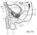
- FIG. 2Eis a coronal sectional view through the prostate gland and adjacent structures showing a percutaneous approach that may be used to implant tissue compression devices(s) (e.g., clips, compression elements, anchoring elements, etc.) to compress or modify the shape of the prostate gland.
- tissue compression devicese.g., clips, compression elements, anchoring elements, etc.
- FIG. 2Fis a coronal sectional view through the prostate gland and adjacent structures showing a percutaneous trans-osseus approach that may be used to implant tissue compression devices(s) (e.g., clips, compression elements, anchoring elements, etc.) to compress or modify the shape of the prostate gland.
- tissue compression devicese.g., clips, compression elements, anchoring elements, etc.
- FIG. 2Gis a coronal sectional view through the prostate gland and adjacent structures showing a percutaneous suprapubic approach that may be used to implant tissue compression devices(s) (e.g., clips, compression elements, anchoring elements, etc.) to compress or modify the shape of the prostate gland.
- tissue compression devicese.g., clips, compression elements, anchoring elements, etc.
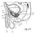
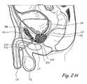
- FIG. 2His a sagittal sectional view through the prostate gland and adjacent structures showing a percutaneous infrapubic approach that may be used to implant tissue compression devices(s) (e.g., clips, compression elements, anchoring elements, etc.) to compress or modify the shape of the prostate gland.
- tissue compression devicese.g., clips, compression elements, anchoring elements, etc.
- FIG. 2Iis a sagittal sectional view through the prostate gland and adjacent structures showing a trans-rectal approach that may be used to implant tissue compression devices(s) (e.g., clips, compression elements, anchoring elements, etc.) to compress or modify the shape of the prostate gland.
- tissue compression devicese.g., clips, compression elements, anchoring elements, etc.
- FIGS. 3A to 3Hshow various components of a system for treating prostate gland disorders by compressing a region of the prostate gland.
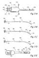
- FIG. 3Ashows the perspective view of an introducer device.
- FIG. 3Bshows a perspective view of an injecting needle that may be used for injecting one or more diagnostic or therapeutic agents in the anatomy.
- FIG. 3Cshows a perspective view of an introducing sheath.
- FIG. 3Dshows a perspective view of a trocar.
- FIG. 3Eshows a perspective view of an anchor delivery device.
- FIG. 3Fshows an enlarged view of the distal region of the device in FIG. 3E .
- FIG. 3Gshows a perspective view of deployed anchors showing radially expanded splayable arms of proximal anchor and distal anchor.
- FIG. 3Hshows a perspective view from the proximal direction of a particular embodiment of the attachment mechanism of FIG. 99E .
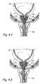
- FIGS. 4A through 4Hshow a coronal section through the prostate gland showing the various steps of a method of treating prostate gland disorders by compressing a region of the prostate gland using the kit shown in FIGS. 3A through 3H .
- FIGS. 4G ′ through 4 H′show the final steps of an embodiment of method of treating prostate gland disorders by deploying a proximal anchor in the urethra.
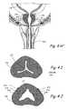
- FIG. 4H ′′shows a coronal section through the prostate gland showing a final deployed configuration of an embodiment of bone anchoring devices for treating prostate gland disorders by compressing a region of the prostate gland.
- FIGS. 4I and 4Jis a cross-sectional view through the prostatic urethra (i.e., the portion of the urethra that passes through the prostate gland) showing the appearance of the urethral lumen before and after performing the method shown in FIGS. 4A through 4H .
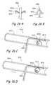
- FIGS. 5A through 5Ishow perspective views of some designs of the tension elements that can be used in the embodiments disclosed elsewhere in this patent application.
- FIG. 5Ashows a perspective view of a tension element comprising a single strand of an untwisted material.
- FIG. 5Bshows a perspective view of a tension element comprising one or more serrations or notches.
- FIG. 5Cshows a perspective view of a tension element comprising multiple filaments of a material twisted together.
- FIG. 5Dshows a perspective view of a tension element comprising a flexible, elastic, spiral or spring element.
- FIG. 5Eshows a perspective view of a tension element comprising a screw threading on the outer surface of tension element.
- FIG. 5Fshows a perspective view of a tension element comprising a hollow shaft comprising one or more collapsible regions.
- FIG. 5Gshows a perspective view of an anchoring device 522 comprising a tension element and two anchors.
- FIG. 5Hshows a perspective view of a tensioning element device comprising a detachable region.
- FIG. 5Ishows a perspective view of a tensioning element comprising telescoping tubes.
- FIGS. 6A through 11Ashow various examples of anchor designs and/or anchoring device designs.
- FIGS. 6A and 6Bshow perspective views of two states of a crumpling anchor.
- FIGS. 7A and 7Bshow sectional views of an undeployed configuration and a deployed configuration respectively of a deployable anchor.
- FIGS. 8A and 8Bshow sectional views of an undeployed configuration and a deployed configuration respectively of a “T” shaped deployable anchor.
- FIGS. 9A through 9Dshow various alternate configurations of the anchoring arms in FIGS. 7A and 7B .
- FIGS. 10A and 10A ′show a distal view and a perspective view respectively of an anchor comprising a spiral element having a three dimensional shape.
- FIGS. 10B and 10B ′show a distal view and a side view respectively of an anchor comprising a spiral element having a two dimensional shape.
- FIGS. 10C and 10C ′show a distal view and a perspective view respectively of an anchor comprising one or more circular elements.
- FIG. 10Dshows a perspective view of an embodiment of an anchoring device comprising an outer ring.
- FIG. 10Eshows a partial perspective view of an anchoring device comprising a hemostatic element.
- FIG. 11Ashows a perspective view of a device having a set of anchors comprising a curved sheet.
- FIGS. 12A through 17Ishow further examples of anchor designs and/or anchoring device designs.
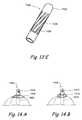
- FIG. 12Ashows a perspective view of an anchor comprising an arrowhead.
- FIG. 12Bshows a cross-sectional view of an anchor comprising a cup-shaped element that encloses a cavity.
- FIG. 12Cshows a perspective view of an anchor comprising a screw.
- FIGS. 13A and 13Bshow perspective views of an uncollapsed state and a collapsed state respectively of an anchor comprising a collapsible region.
- FIGS. 13C and 13Dshow perspective views of an undeployed state and a deployed state respectively of an anchor comprising radially spreading arms.
- FIG. 13Eshows perspective views of an alternate embodiment of an undeployed state of an anchor comprising radially spreading arms.
- FIGS. 14A and 14Bshow perspective views of anchoring devices comprising an adhesive delivering element.
- FIGS. 15A and 15Bshow two configurations of an anchoring device comprising a ratcheted tension element.
- FIG. 16shows a perspective view of an anchor comprising a trocar lumen.
- FIG. 17Ashows a perspective view in the undeployed state of an anchor comprising a rigid or partially flexible T element and a crumpling element.
- FIGS. 17B and 17Cshow various steps of a method to deploy the anchoring device shown in FIG. 17A .
- FIGS. 17D and 17Eshow perspective views of an undeployed and deployed configuration of an anchor comprising a rigid or partially flexible T element with one or more openings or perforations.
- FIGS. 17F and 17Gshow perspective views of an undeployed and deployed configuration of an anchor comprising a stent.
- FIGS. 17H and 17Ishow perspective views of an undeployed and deployed configuration of an anchor comprising a spring.
- FIGS. 18A through 22Eshow various embodiments of mechanisms to deploy one or more anchors.
- FIGS. 18A and 18Bshow a cross-section of an anchor deploying mechanism comprising a screw system.
- FIGS. 19A and 19Bshow a cross-sectional view of an anchor deploying system comprising an electrolytic detachment element.
- FIG. 20shows a perspective view of an anchor deploying system comprising a looped ribbon.
- FIG. 21Ashows a cross-sectional view of an anchor deploying system comprising a locked ball.
- FIGS. 21B and 21Cshow a method of deploying an anchor comprising a locked ball.
- FIGS. 22A through 22Cshow various views of an anchor deploying system comprising two interlocking cylinders.
- FIGS. 22D and 22Eshow the steps of a method of unlocking the two interlocking cylinders from the anchor deploying systems of FIGS. 22A through 22C .
- FIG. 23Ashows a perspective view of a distal end of an anchoring device that has an imaging modality.
- FIGS. 23B through 23Gshow various steps of a method for compressing an anatomical region using the anchoring device of FIG. 23A .
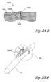
- FIGS. 24A through 24C ′show the device and various steps of a method of compressing an anatomical region using a device with deploying arms deployed through a trocar.
- FIG. 24Dshows a cross-section through the deployed anchoring device of FIG. 24A .
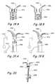
- FIG. 25Ashows a perspective view of a spring clip that can be used to spread the anatomy.
- FIGS. 25B through 25Fshow various steps of a method of spreading an anatomical region or regions using the spring clip of FIG. 25A .
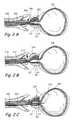
- FIGS. 26A and 26Bshow a cross-sectional view and a perspective view respectively of a mechanism of cinching a tension element or tether to an anchor.
- FIGS. 26C and 26Dshow a partial section through a cinching mechanism comprising a cam element.
- FIG. 26Eshows a sectional view of an embodiment of a cinching mechanism comprising a locking ball.
- FIG. 26Fshows a side view of an embodiment of a cinching mechanism comprising multiple locking flanges.
- FIG. 26Gshows an end view of body of FIG. 26F .
- FIG. 26Hshows a side view of an embodiment of a cinching mechanism comprising a single locking flange.
- FIG. 26Ishows an end view of body of FIG. 26H .
- FIG. 26Jshows an end view of a cinching mechanism comprising a crimping lumen.
- FIGS. 26K and 26Lshow cross-sections of an embodiment of a cinching mechanism comprising a crimping anchor in the undeployed and deployed configurations respectively.
- FIG. 26Mshows a perspective view of an embodiment of a cinching mechanism comprising an element providing a tortuous path to a tension element.
- FIG. 26Nshows a cross-sectional view of an embodiment of a locking mechanism comprising a space occupying anchor securely attached to a tension element.
- FIGS. 26O and 26Pshows a partial sectional view and a perspective view of an embodiment of a cinching mechanism comprising a punched disk.
- FIGS. 26Q and 26Rshow a perspective view of a first embodiment of a cutting device before and after cutting an elongate element.
- FIG. 26Sshow a cross-sectional view of a second embodiment of a cutting device for cutting an elongate element.
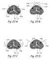
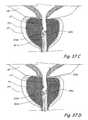
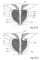
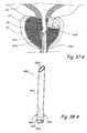
- FIGS. 27A through 27Dshow axial sections through the prostate gland showing various configurations of anchoring devices comprising distal anchors and a tension element.
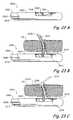
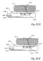
- FIGS. 28 and 28Ashow perspective views of an embodiment of an anchoring device comprising an elongate element comprising multiple barbs or anchors.
- FIGS. 28B through 28Eshow a coronal section through the prostate gland showing various steps of a method of treating the prostate gland using the device of FIG. 28 .
- FIG. 29Ashows an axial section of the prostate gland showing a pair of implanted magnetic anchors.
- FIGS. 29B through 29Dshow a coronal section through the prostate gland showing the steps of a method of implanting magnetic anchors of FIG. 29A .
- FIG. 30Ais a coronal sectional view of a portion of the male urogenital system showing a transurethral approach that may be used to perform a prostate cutting procedure of the present invention.
- FIG. 30Bis a coronal sectional view of a portion of the male urogenital system showing another transurethral approach that may be used to perform a prostate cutting procedure of the present invention.
- FIG. 30Cis a coronal sectional view of a portion of the male urogenital system showing a transurethral/transvesicular approach that may be used to perform a prostate cutting procedure of the present invention.
- FIG. 30Dis a coronal sectional view of a portion of the male urogenital system showing another transurethral approach that may be used to perform a prostate cutting procedure of the present invention, wherein a device advances from the urethra, through the prostate gland, and thereafter accesses the prostate capsule from its outer surface.
- FIG. 31is a coronal sectional view of a portion of the male urogenital system showing a percutaneous/infrapubic approach that may be used to perform a prostate cutting procedure of the present invention.
- FIG. 32is a coronal sectional view of a portion of the male urogenital system showing a percutaneous/transvesicular approach that may be used to perform a prostate cutting procedure of the present invention.
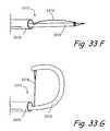
- FIGS. 33A-33Eshows perspective views of various devices that may be included in a system for performing a prostate cutting procedure in accordance with the present invention.
- FIG. 33Ashows a perspective view of an introducer device comprising a first tubular element having a working device lumen.
- FIG. 33Bshows a perspective view of an injecting needle that may be used for injecting one or more diagnostic or therapeutic substances.
- FIG. 33Cshows a perspective view of a guiding device comprising an elongate body comprising a sharp distal tip.
- FIG. 33Dshows a perspective view of a RF cutting device.
- FIG. 33Eshows a perspective view of an embodiment of a plugging device to plug an opening created during a procedure.
- FIGS. 33F through 33Nshow various alternate embodiments of the electrosurgical cutting device in FIG. 33D .
- FIGS. 33F and 33Gshow perspective views of the distal region of a first alternate embodiment of an electrosurgical cutting device in the undeployed and deployed states respectively.
- FIGS. 33H and 33Ishow perspective views of the distal region of a second alternate embodiment of an electrosurgical cutting device in the undeployed and deployed states respectively.
- FIGS. 33J through 33Lshow perspective views of the distal region of a second alternate embodiment of an electrosurgical cutting device showing the steps of deploying the electrosurgical cutting device.
- FIGS. 33M through 33Nshow perspective views of the distal region of a third alternate embodiment of an electrosurgical cutting device showing the steps of deploying the electrosurgical cutting device.
- FIG. 34shows a perspective view of the distal region of a balloon catheter comprising a balloon with cutting blades.
- FIG. 35shows a perspective view of the distal region of a balloon catheter comprising a balloon with cutting wires.
- FIGS. 36A and 36B seriesshow perspective views of an undeployed state and a deployed state respectively of a tissue displacement device.
- FIGS. 36C and 36Dshow a coronal view and a lateral view respectively of a pair of deployed tissue displacement devices of FIGS. 36A and 36B implanted in the prostate gland.
- FIGS. 36E through 36Hshow an axial section through a prostate gland showing the various steps of a method of cutting or puncturing the prostate gland and lining or plugging the cut or puncture.
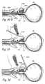
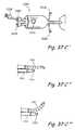
- FIGS. 37A through 37Kshow an embodiment of a method of treating prostate gland disorders by cutting a region of the prostate gland using the devices described in FIG. 33A through 33E .
- FIGS. 38A to 38Dshow various components of a kit for treating prostate gland disorders by compressing a region of the prostate gland.
- FIG. 38Ashows the perspective view of an introducer device.
- FIG. 38Bshows a perspective view of a bridge device
- FIG. 38Cshows a perspective view of a distal anchor deployment device
- FIG. 38Dshows the proximal anchor delivery tool
- FIG. 38Eshows a close-up perspective view of proximal anchor 3833 mounted on proximal anchor delivery tool of FIG. 38D .
- FIG. 1Ashows a sagittal section of a male human body through the lower abdomen showing the male urinary tract.
- the male urinary tractcomprises a pair of tubular organs called ureters (UR) that conduct urine produced by the kidneys.
- the uretersempty into the urinary bladder.
- the urinary bladderis a hollow muscular organ that temporarily stores urine. It is situated posterior to the pubic bone.
- the inferior region of the urinary bladderhas a narrow muscular opening called the bladder neck which opens into a soft, flexible, tubular organ called the urethra.
- the muscles around the bladder neckare called the internal urethral sphincter.
- the internal urethral sphincteris normally contracted to prevent urine leakage.
- the urinary bladdergradually fills with urine until full capacity is reached, at which point the sphincter relaxes. This causes the bladder neck to open, thereby releasing the urine stored in the urinary bladder into the urethra.
- the urethrabegins at the bladder neck, terminates at the end of the penis, and allows for urine to exit the body.
- the region of the urethra just inferior to the urinary bladderis completely surrounded by the prostate gland.
- the prostate glandis part of the male reproductive system and is usually walnut shaped.
- the prostateis divided into lobes.
- the lateral lobesare located lateral to the urethra; the middle lobe is located on the dorsal aspect of the urethra, near the bladder neck.
- the lateral lobesbecome enlarged and act like curtains to close the urethral conduit.
- the middle lobegrows in size and becomes problematic. Because of its superior location near the bladder neck with respect to the urethra, an enlarged middle lobe acts like a ball valve and occludes fluid passage.
- FIG. 1Bshows a coronal section through the lower abdomen of a human male showing a region of the male urinary system.
- the prostate gland (PG)is located around the urethra at the union of the urethra and the urinary bladder.
- FIGS. 2A through 2Hshow various alternate approaches to deploy implantable tissue compression device(s) (e.g., one or more clips, anchoring elements, tensioning members, etc.) to compress the prostate gland PG, thereby relieving constriction of the urethra.
- implantable tissue compression device(s)e.g., one or more clips, anchoring elements, tensioning members, etc.
- FIGS. 2A through 2Hshow various alternate approaches to deploy implantable tissue compression device(s) (e.g., one or more clips, anchoring elements, tensioning members, etc.) to compress the prostate gland PG, thereby relieving constriction of the urethra.
- Specific examples of implantable tissue compression device(s) (e.g., one or more clips, anchoring elements, tensioning members, etc.) useable in this inventionare shown in other figures of this patent application and are described more fully herebelow.
- FIG. 2Ashows a first trans-urethral approach that may be used to implant tissue compression devices(s) to compress the prostate gland PG.
- an introducing device 200is introduced in the urethra through the urethral opening of the penis.
- Introducing device 200comprises an elongate body 202 comprising a lumen that terminates distally in a distal opening 204 .
- One or more working device(s) 206is/are then introduced through distal opening 204 into the urethra.
- the working device(s) 206penetrate the urethral wall and thereafter one or more lobes of the prostate gland. In some applications of the method, working device(s) 206 may further penetrate the prostate capsule and enters the pelvic cavity.
- Working device(s) 206are also used to deploy and implant implantable tissue compression device(s) (e.g., one or more clips, anchoring elements, tensioning members, etc.) to compress the prostate gland PG, thereby relieving constriction of the urethra.
- implantable tissue compression device(s)e.g., one or more clips, anchoring elements, tensioning members, etc.
- FIG. 2Bshows a second trans-urethral approach that may be used to implant tissue compression devices(s) to compress the prostate gland PG.
- an introducing device 210is introduced in the urethra through the urethral opening UO of the penis.
- Introducing device 210comprises an elongate body 212 comprising a lumen that terminates distally in a distal opening 214 .
- One or more working device(s) 216is/are insertable through distal opening 214 into the urethra.
- Working device(s) 216penetrate(s) the urethral wall inferior to the prostate gland and enters the pelvic cavity.
- working device(s) 216penetrate(s) the prostate capsule CP and thereafter one or more lobes of the prostate gland. In some applications of the method the working device(s) 216 may further penetrate the urethral wall enclosed by the prostate gland EG and enters the urethral lumen. Working device(s) 216 may then be used to deploy and implant implantable tissue compression device(s) (e.g., one or more clips, anchoring elements, tensioning members, etc.) to compress the prostate gland PG, thereby relieving constriction of the urethra.
- implantable tissue compression device(s)e.g., one or more clips, anchoring elements, tensioning members, etc.
- FIG. 2Cshows a third trans-urethral approach that may be used to implant tissue compression devices(s) to compress the prostate gland PG.
- an introducing device 220is introduced in the urethra through the urethral opening UO of the penis.
- Introducing device 220comprises an elongate body 222 comprising a lumen that terminates distally in a distal opening 224 .
- Introducing device 220is positioned such that distal opening 224 is located in the urinary bladder UB.
- a one or more working device(s) 226is/are introduced through distal opening 224 into the urinary bladder UB.
- Working device(s) 226penetrate(s) the wall of the urinary bladder UB and thereafter penetrate(s) one or more lobes of the prostate gland PG. In some applications of the method, the working device(s) 226 may further penetrate the prostate capsule and enter the pelvic cavity. Working device(s) 226 may then be used to deploy and implant implantable tissue compression device(s) (e.g., one or more clips, anchoring elements, tensioning members, etc.) to compress the prostate gland PG, thereby relieving constriction of the urethra.
- implantable tissue compression device(s)e.g., one or more clips, anchoring elements, tensioning members, etc.
- FIG. 2Dshows a transperineal approach that may be used to implant tissue compression devices(s) to compress the prostate gland PG.
- an introducing device 230is introduced in the pelvic cavity percutaneously through the perineum.
- Introducing device 230comprises an elongate body 232 comprising a lumen that terminates distally in a distal opening 234 .
- Introducing device 230is positioned such that distal opening 234 is located in the pelvic cavity adjacent to prostate gland.
- one or more working device(s) 236is/are introduced through distal opening 234 into the prostate gland PG.
- Working device(s) 236penetrate(s) the prostate capsule CP and thereafter penetrate(s) one or more lobes of the prostate gland PG.
- the working device(s) 236may further penetrate the urethral wall surrounded by the prostate gland PG and enter the urethral lumen.
- Working device 236may then be used to deploy and implant implantable tissue compression device(s) (e.g., one or more clips, anchoring elements, tensioning members, etc.) to compress the prostate gland PG, thereby relieving constriction of the urethra.
- implantable tissue compression device(s)e.g., one or more clips, anchoring elements, tensioning members, etc.
- FIG. 2Eshows a percutaneous/transvesicular approach that may be used to implant tissue compression devices(s) to compress the prostate gland PG.
- an introducing device 240is introduced percutaneously through the abdominal wall.
- Introducing device 240comprises an elongate body 242 comprising a lumen that terminates distally in a distal opening 244 .
- introducing device 240is advanced through the wall of the urinary bladder UB such that distal opening 244 is located in the urinary bladder UB.
- one or more working device(s) 246is/are introduced through distal opening 244 into the urinary bladder UB.
- One ore more working device(s) 246are advanced through the wall of the urinary bladder UB and into the prostate gland PG. In some applications of the method, working device(s) 246 may further penetrate through the prostate gland capsule and enter the pelvic cavity. Working device(s) 246 is/are then used to deploy and implant implantable tissue compression device(s) (e.g., one or more clips, anchoring elements, tensioning members, etc.) to compress the prostate gland PG, thereby relieving constriction of the urethra.
- implantable tissue compression device(s)e.g., one or more clips, anchoring elements, tensioning members, etc.
- FIG. 2Fshows a percutaneous trans-osseus approach that may be used to implant tissue compression devices(s) to compress the prostate gland PG.
- an introducing device 250is introduced percutaneously through the abdominal wall.
- Introducing device 250comprises an elongate body 252 comprising a lumen that terminates distally in a distal opening 254 .
- Introducing device 250is used to penetrate a pelvic bone (e.g. the pubic bone PB). Thereafter, introducing device 250 is positioned such that distal opening 254 is located adjacent to the prostate gland PG.
- one or more working device(s) 256is/are introduced through distal opening 254 into the prostate gland PG.
- Working device(s) 256penetrate the prostate capsule and thereafter penetrate one or more lobes of the prostate gland PG. In some applications of the method, working device(s) 256 may further penetrate the urethral wall surrounded by the prostate gland and enter the urethral lumen. Working device(s) 256 is/are then used to deploy and implant implantable tissue compression device(s) (e.g., one or more clips, anchoring elements, tensioning members, etc.) to compress the prostate gland PG, thereby relieving constriction of the urethra.
- implantable tissue compression device(s)e.g., one or more clips, anchoring elements, tensioning members, etc.
- FIG. 2Gshows a percutaneous suprapubic approach that may be used to implant tissue compression devices(s) to compress the prostate gland PG.
- an introducing device 260is introduced in the pelvic cavity percutaneously in a trajectory that passes superior to the pubis bone.
- Introducing device 260comprises an elongate body 262 comprising a lumen that terminates distally in a distal opening 264 .
- Introducing device 260is then positioned such that distal opening 264 is located in the pelvic cavity adjacent to prostate gland.
- one or more working device(s) 266is/are introduced through distal opening 264 into the prostate gland PG.
- Working device(s) 266penetrate the prostate capsule CP and thereafter penetrate one or more lobes of the prostate gland PG. In some applications of the method, working device(s) 266 may further penetrate the urethral wall surrounded by the prostate gland and enter the urethral lumen. Working device(s) 266 is/are then used to deploy and implant implantable tissue compression device(s) (e.g., one or more clips, anchoring elements, tensioning members, etc.) to compress the prostate gland PG, thereby relieving constriction of the urethra.
- FIG. 2Hshows a percutaneous infrapubic approach that may be used to implant tissue compression devices(s) to compress the prostate gland. In FIG.
- an introducing device 270is introduced in the pelvic cavity percutaneously in a trajectory that passes inferior to the pubis bone.
- Introducing device 270comprises an elongate body 272 comprising a lumen that terminates distally in a distal opening 274 .
- Introducing device 270is introduced percutaneously in the pelvic cavity in a trajectory that passes inferior to the pubic bone.
- Introducing device 270is then positioned such that distal opening 274 is located in the pelvic cavity adjacent to prostate gland.
- one or more working device(s) 276is/are introduced through distal opening 274 into the prostate gland PG.
- Working device(s) 276penetrate the prostate capsule CP and thereafter penetrate one or more lobes of the prostate gland PG.
- working device(s) 276may further penetrate the urethral wall surrounded by the prostate gland PG and enter the urethral lumen.
- Working device(s) 276is/are then used to deploy and implant implantable tissue compression device(s) (e.g., one or more clips, anchoring elements, tensioning members, etc.) to compress the prostate gland PG, thereby relieving constriction of the urethra.
- implantable tissue compression device(s)e.g., one or more clips, anchoring elements, tensioning members, etc.
- FIG. 2Ishows a trans-rectal approach that may be used to implant tissue compression devices(s) to compress the prostate gland PG.
- an introducing device 280is introduced in the rectum.
- Introducing device 280comprises an elongate body 282 comprising a lumen that terminates distally in a distal opening 284 .
- Introducing deviceis then advanced such that it penetrates the rectal wall and enters the pelvic cavity.
- Introducing device 280is then positioned such that distal opening 284 is located in the pelvic cavity adjacent to prostate gland.
- one or more working device(s) 286is/are introduced through distal opening 284 into the prostate gland PG.
- Working device(s) 286penetrate the prostate capsule CP and thereafter penetrate one or more lobes of the prostate gland. In some applications of the method, working device(s) 286 may further penetrate the urethral wall surrounded by the prostate gland and enter the urethral lumen. Working device(s) 286 is/are then used to deploy and implant implantable tissue compression device(s) (e.g., one or more clips, anchoring elements, tensioning members, etc.) to compress the prostate gland PG, thereby relieving constriction of the urethra.
- implantable tissue compression device(s)e.g., one or more clips, anchoring elements, tensioning members, etc.
- FIGS. 3A to 3Fshow various examples of devices and systems that are useable to treat conditions where the prostate gland PG is compressing a region of the urethra such that the urethra does not expand normally during micturition and urine outflow is impeded.
- FIG. 3Ashows the perspective view of an introducer device 300 .
- Introducer device 300comprises an outer body 301 constructed from suitable biocompatible materials including, but not limited to Pebax, Polyimide, Braided Polyimide, Polyurethane, Nylon, PVC, Hytrel, HDPE, PEEK, metals like stainless steel and fluoropolymers like PTFE, PFA, FEP, EPTFE etc.
- Body 301comprises a working device lumen 302 .
- Distal end of working device lumen 302emerges out of the distal end of body 301 .
- distal end of working device lumen 302has a bent or curved region.
- Proximal end of working device lumen 302emerges out of a first flexible tube 304 .
- first flexible tube 304comprises a stasis valve 306 .
- Body 301further comprises a cystoscope lumen 308 .
- Distal end of cystoscope lumen 308emerges out of the distal end of body 301 .
- Proximal end of cystoscope lumen 308emerges out of a second flexible tube 310 .
- the proximal end of second flexible tube 310comprises a stasis valve 312 .
- Cystoscope lumen 308may comprise one or more side ports e.g. a first side port 318 for the introduction or removal of one or more fluids.
- Working device lumen 302may comprise one or more side ports e.g. a second side port 320 for the introduction or removal of one or more fluids.
- FIG. 3Bshows a perspective view of an injecting needle.
- Injecting needle 330is used for injecting one or more diagnostic or therapeutic substances.
- the injecting needle 330may be used to inject local anesthetic in the urethra, prostate gland and/or tissues near the prostate gland.
- target areas for injecting local anestheticsare the neurovascular bundles, the genitourinary diaphragm, the region between the rectal wall and prostate, etc.
- Examples of local anesthetics that can be injected by injecting needle 330are anesthetic solutions e.g. 1% lidocaine solution; anesthetic gels e.g. lidocaine gels; combination of anesthetic agents e.g.
- Injecting needle 330comprises a hollow shaft 332 made of suitable biocompatible materials including, but not limited to stainless steel 304, stainless steel 306, Nickel-Titanium alloys, titanium etc.
- the distal end of hollow shaft 332comprises a sharp tip 334 .
- the proximal end of hollow shaft 332has a needle hub 336 made of suitable biocompatible materials including, but not limited to metals e.g. stainless steel 304, stainless steel 306, Nickel-Titanium alloys, titanium etc.; polymers e.g.
- needle hub 336comprises a luer lock.
- FIG. 3Cshows an example of an introducing device or introducing sheath 340 .
- Introducing sheath 340comprises a hollow, tubular body 342 made of suitable biocompatible materials including, but not limited to metals e.g. stainless steel 304, stainless steel 306, Nickel-Titanium alloys, titanium etc. or polymers e.g. Pebax, Polyimide, Braided Polyimide, Polyurethane, Nylon, PVC, Hytrel, HDPE, PEEK, PTFE, PFA, FEP, EPTFE etc.
- Tubular body 342further comprises two marker bands: a proximal marker band 344 and a distal marker band 346 . The marker bands can be seen by a cystoscope.
- proximal marker band 344 and distal marker band 346are radiopaque.
- the position of proximal marker band 344 and distal marker band 346is such that after introducing sheath 340 is placed in an optimum location in the anatomy, proximal marker band 344 is located in the urethra where it can be seen by a cystoscope and distal marker band 346 is located in the prostrate gland or in the wall of the urethra where it cannot be seen by a cystoscope.
- Tubular body 342further comprises a series of distance markers 348 on the outer surface of tubular body 342 .
- the proximal end of tubular body 342further comprises a hub 350 made of suitable biocompatible materials including, but not limited to metals e.g. stainless steel 304, stainless steel 306, Nickel-Titanium alloys, titanium etc. or polymers e.g. Pebax, Polyimide, Braided Polyimide, Polyurethane, Nylon, PVC, Hytrel, HDPE, PEEK, PTFE, PFA, FEP, EPTFE etc.
- hub 350comprises a luer lock.
- FIG. 3Dshows a perspective view of a trocar.
- Trocar 360comprises a tubular trocar body 362 .
- the proximal end of trocar body 362comprises a hub 364 .
- Trocar body 362 and hubcan be constructed from suitable biocompatible materials including, but not limited to metals e.g. stainless steel 304, stainless steel 306, Nickel-Titanium alloys, titanium etc. or polymers e.g. Pebax, Polyimide, Braided Polyimide, Polyurethane, Nylon, PVC, Hytrel, HDPE, PEEK, PTFE, PFA, FEP, EPTFE etc.
- Distal end of trocar body 362ends in a sharp trocar tip 366 .
- FIG. 3Eshows a perspective view of an anchor delivery device.
- Anchor delivery device 370comprises a body 372 having a distal opening 373 . A section of the distal region of body 372 has been removed to show a view of the anchor assembly.
- Body 372encloses a distal anchor 374 and a proximal anchor 376 .
- Proximal anchor 376 and distal anchor 374can have a variety of designs including, but not limited to the designs disclosed elsewhere in this patent application.
- Proximal anchor 376 and distal anchor 374can be constructed from suitable biocompatible materials including, but not limited to metals e.g. stainless steel 304, stainless steel 306, Nickel-Titanium alloys, titanium etc. or polymers e.g.
- proximal anchor 9976 and distal anchor 9974comprise splayable elements that expand in a radially outward direction when a radial compression force, as enacted by body lumen 9972 , on proximal anchor 9976 and distal anchor 9974 is removed.
- the splayable elementscan be made of suitable super-elastic materials such as Nickel-Titanium alloys etc.
- Tension element 9978can be made of suitable elastic or non-elastic materials including, but not limited to metals e.g. stainless steel 304, stainless steel 306, Nickel-Titanium alloys, suture materials, titanium etc. or polymers such as silicone, nylon, polyamide, polyglycolic acid, polypropylene, Pebax, PTFE, ePTFE, silk, gut, or any other braided or mono-filament material.
- Tension element 9978can have a variety of designs including the designs shown in FIGS. 5A through 5F . As shown in FIG.
- proximal end of proximal anchor 9976is connected by an attachment mechanism 9980 to a torquable shaft 9982 .
- the proximal end of torquable shaft 9982is attached to a control button 9984 .
- Control button 9984can be used to deploy proximal anchor 9976 by sliding control button 9984 along groove 9985 in the distal direction.
- Control button 9984is then used to deploy distal anchor 9974 by turning control button 9984 in the circumferential direction along groove 9985 .
- FIG. 3Hshows a perspective view from the proximal direction of a particular embodiment of the attachment mechanism of FIG. 3E .
- Attachment mechanism 380comprises a circular plate 386 made from suitable biocompatible materials including, but not limited to metals e.g. stainless steel 304, stainless steel 306, Nickel-Titanium alloys, titanium etc. or polymers e.g. Polycarbonate, PVC, Pebax, Polyimide, Polyurethane, Nylon, Hytrel, HDPE, PEEK, PTFE, PFA, FEP etc.
- the proximal face of circular plate 386is connected to torquable shaft 382 .
- Circular plate 386further comprises a semicircular groove 388 .
- One end of semicircular groove 388comprises an enlarged region 390 .
- a knob 392 located on the proximal portion of proximal anchor 376slides on semicircular groove 388 .
- the size of knob 322is larger than the size of semicircular groove 388 but smaller than size of enlarged region 390 .
- control button 384is turned in the circumferential direction along groove 385 , torquable shaft 382 is turned. This turns circular plate 386 causing knob 392 to slide on the groove 388 .
- knob 392reaches enlarged region 390 . This releases knob 392 from circular plate 386 thereby releasing proximal anchor 376 from anchor delivery device 370 .
- FIGS. 4A through 4Hshow a coronal section through the prostate gland showing the various steps of a method of treating prostate gland disorders by compressing a region of the prostate gland using the kit shown in FIGS. 3A through 3F .
- introducer device 300is introduced in the urethra through the urethral opening at the tip if the penis.
- a cystoscopeis inserted in introducer device 300 through cystoscope lumen 308 such that the lens of the cystoscope is located in the distal opening of cystoscope lumen.
- the cystoscopeis used to navigate introducer device 300 through the urethra such that the distal region of introducer device 300 is located in a target region in the prostatic urethra.
- injecting needle 330is advanced through working device lumen 302 such that the distal tip of injecting needle 330 penetrates into a region of the urethral wall or the prostate gland. Injecting needle 330 is then used to inject one or more diagnostic or therapeutic agents into the urethral wall or the prostate gland. This step may be repeated one or more times to inject one or more diagnostic or therapeutic agents in one or more regions of the urethral wall and/or the prostate gland. In one method embodiment, injecting needle 330 is used to inject an anesthetic in one or more regions of the urethral wall and/or the prostate gland. In another embodiment, injecting needle 330 is used to deliver energy in the form of radiofrequency energy, resistive heating, laser energy, microwave energy etc.
- injecting needle 330is used to deliver alpha antagonist agents, such as phenoxybenzamine, prazosin, doxazosin, terazosin, tamsulosin, alfuzosin etc.
- injecting needle 330is used to deliver anti-androgen, such as flutamide or 5-alpha reductase inhibitors, such as finasteride, dutasteride, 3-oxosteroid compounds, 4-aza-3-oxosteroid derivatives of testosterone etc.
- injecting needle 330is used to deliver anti-inflammatory agents, such as rapamycin, paclitaxel, ABT-578, everolimus, taxol etc.
- injecting needle 330is used to deliver ablative agents such as methyl alcohol etc.
- injecting needle 330is used to deliver energy in the form of radiofrequency energy, resistive heating, laser energy, microwave energy etc.
- injecting needle 330is used to deliver alpha antagonist agents, such as phenoxybenzamine, prazosin, doxazosin, terazosin, tamsulosin, alfuzosin etc.
- injecting needle 330is used to deliver anti-androgen, such as flutamide or 5-alpha reductase inhibitors, such as finasteride, dutasteride, 3-oxosteroid compounds, 4-aza-3-oxosteroid derivatives of testosterone etc.
- injecting needle 330is used to deliver anti-inflammatory agents, such as rapamycin, paclitaxel, ABT-578, everolimus, taxol etc. In another embodiment, injecting needle 330 is used to deliver ablative agents such as methyl alcohol etc.
- step 4 Cinjecting needle 330 is withdrawn from introducer device 300 .
- introducer sheath 340 and trocar 360are advanced through working device lumen 302 .
- introducer sheath 340 and trocar 360are advanced till the distal tip of trocar 360 penetrates the capsule of the prostate gland and the distal end of introducer sheath 340 is located outside the prostate gland in the pelvic cavity.
- trocar 360is withdrawn from working device lumen 302 leaving introducer sheath 340 in place.
- anchor delivery device 370is introduced through the lumen of introducer sheath 340 till the distal end of body 372 protrudes through the distal tip of introducer sheath 340 .
- distal anchor 374is deployed. It should be noted that the anchor may be carried to the site and deployed from within an introducer, on the outside of an introducer, or it may be the distal tip of the introducer itself. Thereafter, anchor deliver device 370 is pulled in the proximal direction along with introducer sheath 340 so that distal anchor 374 is anchored on the outer surface of the prostate capsule. This step may be used to create tension in the tension element 378 . In one method embodiment, anchor deliver device 370 is pulled in the proximal direction along with introducer sheath 340 such that the distal end of anchor delivery device 370 is located in the prostate gland.
- anchor deliver device 370is pulled in the proximal direction along with introducer sheath 340 till the distal end of anchor delivery device 370 is located in the urethral wall or the urethral lumen.
- proximal anchor 376is deployed. Proximal anchor 376 may be deployed in the prostate gland, in the urethral wall or in the urethral lumen. Proximal anchor 376 is still attached by attachment mechanism 380 to anchor delivery device 370 . The proximal anchor may be pre-loaded on the tension element, or may subsequently be loaded by the operator on the tension element.
- FIGS. 4G through 4Hshow the steps of deploying proximal anchor 376 in the prostate gland. In FIG.
- proximal anchor 376is separated from anchor delivery device 370 . This separation may be achieved via numerous means including cutting, melting, un-locking a link, or breaking the tensioning element at a desired location. Ideally this residual end of the tensioning element will not protrude substantially into the lumen of the urethra. Thus proximal anchor 376 and distal anchor 374 are anchored in the anatomy. Thereafter, anchor delivery device 370 and introducer sheath 340 are both pulled in the proximal direction and are withdrawn into introducer device 300 . Thereafter, introducer device 300 is pulled in the proximal direction to pull it out of the urethra. In FIG. 4H , the steps from FIG. 4A through 4G are repeated in a second region of the prostate gland if desired to implant two or more sets of anchoring devices.
- FIGS. 4G ′ through 4 H′show the steps of deploying proximal anchor 376 in the urethra.
- proximal anchor 376is separated from anchor delivery device 370 in the urethra.
- proximal anchor 376 and distal anchor 374are anchored in the urethra and the prostate capsule respectively.
- anchor delivery device 370 and introducer sheath 340are both pulled in the proximal direction and are withdrawn into introducer device 300 .
- introducer device 300is pulled in the proximal direction to pull it out of the urethra.
- FIG. 4H ′the steps from FIG.
- 4A through 4G ′are repeated optionally in a second region of the prostate gland to implant two or more sets of anchoring devices. It should be understood that this method and devices may be applied to any lobe (middle or lateral lobes) of the prostate and further more may be used multiple times in the same lobe to achieve the desired effect.
- FIG. 4H ′′shows a coronal section through the prostate gland showing the final deployed configuration of an embodiment of bone anchoring devices for treating prostate gland disorders by compressing a region of the prostate gland.
- introducer sheath 340 and trocar 360are advanced till the distal tip of trocar 360 penetrates a bone in the abdomen (e.g. the pelvic bone, etc.) and the distal end of introducer sheath 340 is located outside the bone.
- trocar 360is withdrawn from working device lumen 302 leaving introducer sheath 340 in place.
- anchor delivery device 370is introduced through the lumen of introducer sheath 340 until the distal end of body 372 touches the bone through the distal tip of introducer sheath 340 .
- distal anchor 374is implanted in the bone.
- Distal anchor 374may comprise a variety of designs including, but not limited to designs of distal tips of Kirschner wires. Examples of such Kirschner wire distal tips are spiral drill tips, lancer tips, threaded trocar tips, lengthwise knurled tips, 3-sided trocar tips, 4-sided trocar tips,
- anchor deliver device 370is pulled in the proximal direction along with introducer sheath 340 . This step creates tension in the tension element 378 .
- anchor deliver device 370is pulled in the proximal direction along with introducer sheath 340 till the distal end of anchor delivery device 370 is located in the urethral wall or the urethral lumen.
- the remaining method stepsare similar to steps 4 F through 4 H.
- One or more anchors disclosed in this patent applicationmay be implanted in anatomical locations that include, but are not limited to:
- FIGS. 4I and 4Jshow a cross-section of the urethra through the prostate gland PG showing the appearance of the urethral lumen before and after performing the method shown in FIGS. 4A through 4H .
- FIG. 4Ishows a cross-section of the urethra through the prostate gland showing the appearance of the urethral lumen in a patient with BPH.
- FIG. 4Jshows a cross-section of the urethra through the prostate gland PG showing the appearance of the urethral lumen after performing the procedure shown in FIGS. 4A through 4H .
- the urethral lumen shown in FIG. 4Iis larger than the urethral lumen in FIG. 4J .
- FIGS. 5A through 5Fshow perspective views of some designs of the tension elements that can be used in the embodiments disclosed elsewhere in this patent application.
- FIG. 5Ashows a perspective view of a tension element 500 comprising a single strand of an untwisted material.
- materials that can be used to manufacture tension element 500include but are not limited to synthetic fibers e.g. various grades of Nylon, polyethylene, polypropylene, polyester, Aramid etc.; metals e.g. various grades of stainless steel, titanium, nickel-titanium alloys, cobalt-chromium alloys, tantalum etc.; natural fibers e.g. cotton, silk etc.; rubber materials e.g. various grades of silicone rubber etc.
- FIG. 1shows a perspective view of a tension element 500 comprising a single strand of an untwisted material.
- synthetic fiberse.g. various grades of Nylon, polyethylene, polypropylene, polyester, Aramid etc.
- metalse.g. various grades of stainless steel,
- FIG. 5Bshows a perspective view of a tension element 502 comprising one or more serrations 504 or notches. Serrations 504 may be aligned in a particular direction to allow relatively easy movement of an outer body along tension element 502 in one direction and offer significant resistance to movement of the outer body along the tension element in the other direction.
- FIG. 5Cshows a perspective view of a tension element 506 comprising multiple filaments 507 of a material twisted together. Examples of materials that can be used include to manufacture multiple filaments 507 include but are not limited to synthetic fibers e.g. various grades of Nylon, polyethylene, polypropylene, polyester, Aramid etc.; metals e.g.
- FIG. 5Dshows a perspective view of a tension element 509 comprising a flexible, elastic, spiral or spring element.
- tension element 509examples include but are not limited to metals e.g. various grades of stainless steel, titanium, nickel-titanium alloys, cobalt-chromium alloys, tantalum etc.
- FIG. 5Eshows a perspective view of a tension element 510 comprising a screw threading 511 on the outer surface of tension element 510 . Screw threading 511 enables tension element 510 to be screwed through an outer element to advance or withdraw tension element through the outer element.
- FIG. 5Fshows a perspective view of a tension element 512 comprising a hollow shaft 514 comprising one or more collapsible regions 516 .
- a collapsible region 516comprises one or more windows 518 .
- Windows 518are cut in hollow shaft 514 in such a way that several thin, collapsible struts 520 are created between adjacent windows 518 .
- tension element 512is compresses along its length, collapsible struts 520 are deformed in the radially outward direction to create one or more anchoring regions.
- FIG. 5Gshows a perspective view of an anchoring device 522 comprising a tension element and two anchors. Distal end of a tension element 524 is attached to a distal anchor 526 . Proximal end of tension element 524 is attached to a proximal anchor 528 .
- FIG. 5Hshows a perspective view of a tensioning element device comprising a detachable region.
- Anchoring device 530comprises a first anchor 532 and a second anchor 534 .
- First anchor 532 and second anchor 534may comprise a variety of anchor designs disclosed elsewhere in this patent application.
- one or both of first anchor 532 and second anchor 534comprise a substantially flat plate.
- the substantially flat platemay be made from various materials including, but not limited to metals e.g. various grades of stainless steel, titanium, nickel-titanium alloys, cobalt-chromium alloys, tantalum etc.; polymers e.g. polypropylene, Teflon etc.; synthetic fibers e.g.
- First anchor 532 and second anchor 534are connected to a tensioning element.
- the tensioning elementcomprises two flexible members: a first tensioning member 536 and a second tensioning member 538 .
- the distal end of first tensioning member 536is connected to first anchor 532 and the proximal end of second tensioning member 538 is connected to second anchor 534 .
- Proximal end of first tensioning member 536 and distal end of second tensioning member 538are connected to a releasable member 540 .
- Releasable member 540can be releasably connected to a deploying device.
- first anchor 532is deployed out of an anatomical tissue (e.g. the prostate gland) into a first anatomical cavity (e.g. the pelvic cavity).
- second anchor 534is deployed into a second anatomical cavity (e.g. the urethral lumen).
- releasable member 540is released from the deploying device to deliver anchoring device 530 in a target region.
- FIG. 5Ishows a perspective view of a tensioning element comprising telescoping tubes.
- Tensioning element 544may comprise two or more telescoping tubes.
- tensioning element 544comprises three telescoping tubes: a first telescoping tube 546 , a second telescoping tube 548 and a third telescoping tube 550 .
- Second telescoping tube 548slidably fits into a lumen of first telescoping tube 546 .
- third telescoping tube 550slidably fits into a lumen of second telescoping tube 548 .
- the telescoping tubeshave a locking mechanism to prevent a telescoping tube from completely disengaging from another telescoping tube.
- the telescoping tubesmay be made from a variety of biocompatible materials including, but not limited to plastics, metals etc.
- All the components of the systems disclosed hereinmay be coated or embedded with therapeutic or diagnostic substances (e.g., drugs or therapeutic agents) or such therapeutic or diagnostic substances may be introduced into or near the prostate or adjacent tissue through a catheter, cannula needles, etc.
- therapeutic or diagnostic substancese.g., drugs or therapeutic agents
- therapeutic and diagnostic substancesinclude but are not limited to: hemostatic agents; antimicrobial agents (antibacterials, antibiotics, antifungals, antiprotozoals; antivirals; antimicrobial metals (e.g., silver, gold, etc.); hemostatic and/or vasoconstricting agents (e.g., pseudoephedrine, xylometazoline, oxymetazoline, phenylephrine, epinephrine, cocaine, etc.); local anesthetic agents (lidocaine, cocaine, bupivacaine); hormones; anti-inflammatory agents (steroidal and non-steroidal); hormonally active agents; agents to enhance potency; substances to dissolve, degrade, cut, break, weaken, soften, modify or remodel connective tissue or other tissues; (e.g., enzymes or other agents such as collagenase (CGN), trypsin, trypsin/EDTA, hyaluronidase, and tosyllys
- CGNcollagenase
- antitumor agentse.g., cancer chemotherapeutic agents, biological response modifiers, vascularization inhibitors, hormone receptor blockers, cryotherapeutic agents or other agents that destroy or inhibit neoplasia or tumorigenesis
- alkylating agents or other agents which directly kill cancer cells by attacking their DNAe.g., cyclophosphamide, isophosphamide
- nitrosoureas or other agents which kill cancer cells by inhibiting changes necessary for cellular DNA repaire.g., carmustine (BCNU) and lomustine (CCNU)
- antimetabolites and other agents that block cancer cell growth by interfering with certain cell functionsusually DNA synthesis (e.g., 6 mercaptopurine and 5-fluorouracil (5FU), antitumor antibiotics and other compounds that act by binding or intercalating DNA and preventing RNA synthesis (e.g., doxorubicin, daunorubi
- biological response modifierse.g., interferon, bacillus calmette-guerin (BCG), monoclonal antibodies, interluken 2, granulocyte colony stimulating factor (GCSF), etc.
- PGDF receptor antagonistsherceptin, asparaginase, busulphan, carboplatin, cisplatin, carmustine, chlorambucil, cytarabine, dacarbazine, etoposide, flucarbazine, fluorouracil, gemcitabine, hydroxyurea, ifosphamide, irinotecan, lomustine, melphalan, mercaptopurine, methotrexate, thioguanine, thiotepa, tomudex, topotecan, treosulfan, vinblastine, vincristine, mitoazitrone, oxaliplatin, pro
- biological response modifierse.g., interferon, bacillus calmette-guerin (
- the substances delivered in this inventionmay include cells (mucosal cells, fibroblasts, stem cells or genetically engineered cells) as well as genes and gene delivery vehicles like plasmids, adenoviral vectors or naked DNA, mRNA, etc. injected with genes that code for anti-inflammatory substances, etc., and, as mentioned above, macrophages or giant cells that modify or soften tissue when so desired, cells that participate in or effect the growth of tissue.
- Anchoring device embodimentscan hold tissue in compression for extended periods of time such that the compression influences the remodeling response. Localized compression of tissue can induce a localized response.
- One mechanism of action of anchoring device embodimentsis localized tissue remodeling in response to persistent compression.
- Compression of prostate tissuecan reduce the local blood flow in the region by mechanical constriction and even obstruction of the vasculature. After one month, the localized compression of the prostate can result in a reduction of local blood flow and subsequent loss of glandular epithelium atrophy. Necrosis of prostatic tissue can also result from sustained compression.
- the localized compressioncan reach an end-stage where the tissue has remodeled to steady state morphology.
- This morphologyis characterized by atrophy of the prostatic lobe and/or dilation of the porous glandular regions. Again, necrosis can also result from sustained compression.
- the anchoring devicecan be made from bioabsorbable materials such as polylactic acid (PLA) and copolymers of polylactic acid, polyglycolic acid and copolymers of polyglycolic acid, copolymers of PLA and PGA, silk, polyester, silicone, collagen, and polymers of glycolide and lactide.
- PLApolylactic acid
- the bioabsorbable anchoring devicescan provide the long-term tissue remodeling that reduces or eliminates symptoms of BPH without the risks generally associated with permanent implants.
- compression provided by the anchoring devicemay be evidenced by detectably displaced prostatic urethra in the area surrounding the anchoring device.
- visual inspection of the urethra using a cystoscope or other visualization toolcan provide evidence of displacement indicative of compression which would in turn induce remodeling, including lobular atrophy and/or necrosis.
- histomorphological assessment of human tissueis not required to provide evidence of sufficient compression of prostatic tissue for inducing remodeling; instead visual evidence of urethral displacement (for example, displacement relative to a baseline value for a patient) demonstrates compression, which can induce remodeling.
- FIGS. 6A through 11Ashow various examples of anchor designs and/or anchoring device designs.
- FIGS. 6A and 6Bshow examples of a crumpling anchor 600 .
- crumpling anchor 600comprises a substantially flattened body 602 .
- Body 602can be made of a variety of materials including, but not limited to synthetic fibers e.g. various grades of Nylon, polyethylene, polypropylene, polyester, Aramid etc.; metals e.g. various grades of stainless steel, titanium, nickel-titanium alloys, cobalt-chromium alloys, tantalum etc.; natural fibers e.g. cotton, silk etc.; rubber materials e.g. various grades of silicone rubber etc.
- any or all of the anchors, the tensioning element(s) and any other componentsmay be coated, impregnated, embedded or otherwise provided with substance(s) (e.g., drugs, biologics, cells, etc.) to reduce the likelihood of infection, inflammation, treat the prostatic adenoma directly or enhance the likelihood of endothelialization, deter adhesion formation, promote healing or otherwise improve the likelihood or degree of success of the procedure.
- substance(s)e.g., drugs, biologics, cells, etc.
- Such substance(s)may be released primarily at the time of delivery or may be released over a sustained period. Examples of such substances are listed above and include but are not limited to certain metals with bacteriostatic action (i.e.
- Body 602may be non-woven or woven. Body 602 may have a variety of shapes including, but not limited to square, rectangular, triangular, other regular polygonal, irregular polygonal, circular etc. Body 602 may have a substantially one dimensional, two dimensional or three dimensional shape. The material chosen for this device may have hemostatic properties to reduce bleeding from the implantation tract or site.
- Body 602further comprises one or more attachment means 606 .
- Attachment meansare used to create a channel in the body 602 through which tension element 604 passes.
- Crumpling anchor 600is introduced through a region of tissue (e.g. through prostate gland tissue) into a cavity or lumen e.g. pelvic cavity, urethral lumen etc.
- FIG. 6Btension element 604 is pulled in the proximal direction.
- FIGS. 7A and 7Bshow an example of a deployable anchor 700 in an undeployed configuration and a deployed configuration, respectively.
- This deployable anchor 700comprises one or more anchoring arms 702 .
- Anchoring arms 702may be made from a variety of elastic, super-elastic or shape memory materials etc. Typical examples of such materials include but are not limited to metals e.g. stainless steel, titanium, nickel-titanium alloys, cobalt-chromium alloys, tantalum etc.
- Anchoring arms 702are connected to a central hub 704 . Central hub in turn is connected to the distal end of a tension element 706 .
- FIG. 7Aanchoring arms 702 are folded inside a hollow deploying sheath 708 .
- FIG. 7Bdeploying sheath 708 is pulled in the proximal direction. This releases anchoring arms 702 from the distal end of deploying sheath 702 . This causes anchoring arms 702 to open in the radially outward direction. Anchor 700 can then anchor to tissue and resist movement of tension element 706 in the proximal direction.
- FIGS. 8A and 8Bshow sectional views of an undeployed configuration and a deployed configuration respectively of a “T” shaped deployable anchor.
- Anchor 8110comprises an elongate region 802 .
- Elongate region 802may be made from a variety of elastic, super-elastic or shape memory materials etc. Typical examples of such materials include but are not limited to metals e.g. stainless steel, titanium, nickel-titanium alloys, cobalt-chromium alloys, tantalum etc; polymers e.g. polypropylene, Teflon etc.
- Middle section of elongate region 802is connected to the distal end of a tension element 804 to form a “T” shaped anchor.
- middle section of elongate region 802is connected to the distal end of a tension element 804 by a hinge.
- elongate region 802is folded inside a hollow deploying sheath 806 . This reduces the undeployed diameter of the distal region of anchor 8110 and also prevents unwanted anchoring of elongate region 802 to tissue.
- deploying sheath 806is pulled in the proximal direction. This releases elongate region 802 from the distal end of deploying sheath 806 . This in turn causes elongate region 802 to twist and orient itself perpendicular to the distal end of a tension element 804 .
- Anchor 800can then anchor to tissue and resist movement of tension element 804 in the proximal direction.
- Anchoring arms 702 in FIGS. 7A and 7Bcan have a variety of configurations including, but not limited to configurations shown in FIGS. 9A through 9D .
- FIG. 9Ashows a distal end view of an embodiment of an anchor comprising two triangular arms.
- Anchor 900comprises two anchor arms 902 .
- Anchor arms 902can be made of a variety of materials including, but not limited to metals e.g. stainless steel, titanium, nickel-titanium alloys, cobalt-chromium alloys, tantalum etc; polymers e.g. polypropylene, Teflon etc.
- Anchor arms 902are connected to a tension element 904 .
- anchor arms 902are connected to a central hub, which in turn is connected to tension element 904 .
- the arms in each of these devicesmay be folded or contained prior to deployment through the use of a sheath or grasping or mounting device.
- FIG. 9Bshows a distal end view of an embodiment of an anchor comprising four rectangular arms.
- Anchor 906comprises four anchor arms 908 .
- Anchor arms 908can be made of a variety of materials including, but not limited to metals e.g. stainless steel, titanium, nickel-titanium alloys, cobalt-chromium alloys, tantalum etc; polymers e.g. polypropylene, Teflon etc.
- Anchor arms 908are connected to a tension element 910 .
- anchor arms 908are connected to a central hub, which in turn is connected to tension element 910 .
- FIG. 9Cshows a distal end view of an embodiment of an anchor comprising a mesh or a woven material.
- Anchor 912comprises four anchor arms 914 .
- Anchor arms 914can be made of a variety of materials including, but not limited to metals e.g. stainless steel, titanium, nickel-titanium alloys, cobalt-chromium alloys, tantalum etc; polymers e.g. polypropylene, Teflon etc.
- Anchor arms 914are connected to a tension element 916 .
- anchor arms 914are connected to a central hub, which in turn is connected to tension element 916 .
- Porous material 918comprises a plurality of pores that allow for tissue ingrowth. Porous material 918 may also help to distribute the pressure on anchor arms 914 over a wider area.
- Porous material 918can be made of variety of materials including, but not limited to synthetic fibers e.g. various grades of Nylon, polyethylene, polypropylene, polyester, Aramid etc.; metals e.g. various grades of stainless steel, titanium, nickel-titanium alloys, cobalt-chromium alloys, tantalum etc.; natural fibers e.g. cotton, silk etc.; rubber materials e.g. various grades of silicone rubber etc. Porous material 918 may be non-woven or woven.
- FIG. 9Dshows a distal end view of an embodiment of an anchor comprising four curved arms.
- Anchor 920comprises four curved anchor arms 922 .
- Curved anchor arms 922can be made of a variety of materials including, but not limited to metals e.g. stainless steel, titanium, nickel-titanium alloys, cobalt-chromium alloys, tantalum etc; polymers e.g. polypropylene, Teflon etc.
- Curved anchor arms 922are connected to a tension element 924 .
- curved anchor arms 922are connected to a central hub which in turn is connected to tension element 924 .
- FIG. 10Ashows a distal end view of an anchor comprising a spiral element having a three dimensional shape.
- Anchor 1000comprises a three dimensional spiral element 1002 .
- Diameter of spiral element 1002may be substantially constant or may substantially vary along the length of spiral element 1002 .
- Spiral element 1002may be made of an elastic, super-elastic or shape memory materials.
- Spiral element 1002may be made of a variety of materials including, but not limited to metals e.g. various grades of stainless steel, titanium, nickel-titanium alloys, cobalt-chromium alloys, tantalum etc.; polymers e.g. polypropylene, Teflon etc.; synthetic fibers e.g.
- FIG. 10A ′shows a side view of the anchor in FIG. 10A .
- FIG. 10A ′shows anchor 1000 comprising spiral element 1002 connected to central hub 1004 which in turn is connected to a tension element 1006 .
- FIG. 10Bshows a distal end view of an anchor comprising a spiral element having a two dimensional shape.
- Anchor 1000comprises a two dimensional spiral element 1010 .
- Spiral element 1010may be made of an elastic, super-elastic or shape memory materials.
- Spiral element 1010may be made of a variety of materials including, but not limited to metals e.g. various grades of stainless steel, titanium, nickel-titanium alloys, cobalt-chromium alloys, tantalum etc.; polymers e.g. polypropylene, Teflon etc.; synthetic fibers e.g. various grades of Nylon, polyethylene, polypropylene, polyester, Aramid etc.; natural fibers e.g. cotton, silk etc.; rubber materials e.g. various grades of silicone rubber etc.
- Spiral element 1010is connected to a central hub 1012 which in turn is connected to a tension element.
- spiral element 1010is directly connected to a tension element without using central hub 1012 .
- FIG. 10B ′shows a side view of the anchor in FIG. 10B .
- FIG. 10B ′shows anchor 1008 comprising spiral element 1010 connected to central hub 1012 which in turn is connected to a tension element 1014 .
- FIG. 10Cshows a distal end view of an anchor comprising one or more circular elements.
- anchor 1016comprises an inner circular element 1018 and an outer circular element 1020 .
- a series of radial arms or struts 1022connect inner circular element 1018 to outer circular element 1020 and to a central hub 1024 .
- Central hub 1024may have a lumen 1026 .
- Anchor 1016may be substantially two dimensional or three dimensional.
- FIG. 10C ′shows a perspective view of the anchor in FIG. 10C .
- FIG. 10C ′shows an anchor 1016 comprising an inner circular element 1018 , an outer circular element 1020 and series of radial arms or struts 1022 connecting inner circular element 1018 to outer circular element 1020 and to a central hub 1024 .
- Central hub 1024is connected to a tension element.
- FIG. 10Dshows a perspective view of an embodiment of an anchoring device comprising an outer ring.
- Anchor 1040comprises a central hub 1042 and an outer ring 1044 .
- central hub 1042acts as a plug to plug an opening in the anatomy to reduce or prevent bleeding or leakage of fluids.
- Central hub 1042is connected to outer ring 1044 by one or more bars or struts 1046 .
- central hub 1042is connected to an inner ring 1048 which in turn is connected to outer ring 1044 by one or more bars or struts 1046 .
- Central hub 1042further comprises a locking element 1050 .
- Locking element 1050comprises a lumen 1052 through which a tension element can slide.
- Anchor 1040may be made from a variety of materials including, but not limited to synthetic fibers e.g. various grades of Nylon, polyethylene, polypropylene, polyester, Aramid etc.; metals e.g. various grades of stainless steel, titanium, nickel-titanium alloys, cobalt-chromium alloys, tantalum etc.; natural fibers e.g. cotton, silk etc.; rubber materials e.g. various grades of silicone rubber etc.
- synthetic fiberse.g. various grades of Nylon, polyethylene, polypropylene, polyester, Aramid etc.
- metalse.g. various grades of stainless steel, titanium, nickel-titanium alloys, cobalt-chromium alloys, tantalum etc.
- natural fiberse.g. cotton, silk etc.
- rubber materialse.g. various grades of silicone rubber etc.
- FIG. 10Eshows a partial perspective view of an anchoring device comprising a hemostatic element.
- Anchor 1060comprises a central hub 1062 .
- central hub 1062acts as a plug to plug an opening in the anatomy to reduce or prevent bleeding or leakage of fluids.
- Central hub 1062comprises a cinching mechanism to allow central hub 1062 to cinch on to a tension element 1064 passing through central hub 1062 .
- the free end 1066 of tension element 1064is severed to minimize the presence of tension element 1064 in the anatomy.
- Anchor 1060further comprises an outer ring 1068 .
- Central hub 1062is connected to outer ring 1068 by one or more struts 1070 .
- Anchor 1060further comprises a mesh or porous element 1072 between outer ring 1068 and struts 1070 .
- the mesh or porous element 1072may be concave shaped as shown in FIG. 10E .
- Mesh or porous element 1072allows for tissue ingrowth over a period of time thus providing additional securing of anchor 1060 to tissue.
- FIG. 11Ashows a perspective view of a device having a set of anchors comprising a curved sheet.
- Anchoring device 1100may comprise one or more anchors comprising a curved sheet.
- anchoring device 1100comprises a first anchor 1102 and a second anchor 1104 .
- First anchor 1102 and second anchor 1104may comprise elastic, super elastic or shape memory materials.
- First anchor 1102 and second anchor 1104may be made from various materials including, but not limited to metals e.g. various grades of stainless steel, titanium, nickel-titanium alloys, cobalt-chromium alloys, tantalum etc.; polymers e.g. polypropylene, Teflon etc.; synthetic fibers e.g.
- first anchor 1102is deployed out of an anatomical tissue (e.g. the prostate gland) into a first anatomical cavity (e.g. the pelvic cavity). Thereafter, second anchor 1104 is deployed into a second anatomical cavity (e.g. the urethral lumen).
- anatomical tissuee.g. the prostate gland
- first anatomical cavitye.g. the pelvic cavity
- second anchor 1104is deployed into a second anatomical cavity (e.g. the urethral lumen).
- This method embodimenthas the advantage of using the natural curvature of first anchor 1102 and second anchor 1104 to distribute pressure on first anchor 1102 and second anchor 1104 over a large area.
- FIGS. 12A through 17Ishow further examples of anchor designs and/or anchoring device designs.
- FIG. 12Ashows a perspective view of an anchor comprising an arrowhead.
- Anchor 1200comprises an arrowhead 1202 .
- Arrowhead 1202may be made from various materials including, but not limited to metals e.g. various grades of stainless steel, titanium, nickel-titanium alloys, cobalt-chromium alloys, tantalum etc.; polymers e.g. polypropylene, Teflon etc.; rubber materials e.g. various grades of silicone rubber etc.
- Arrowhead 1202may comprise a sharp distal tip.
- Arrowhead 1202may have a three dimensional or a substantially two dimensional design.
- FIG. 12Bshows a cross-sectional view of an anchor comprising a cup-shaped element that encloses a cavity.
- Anchor 1208comprises a cup-shaped element 1210 .
- Proximal, concave surface of cup-shaped element 1210encloses a cavity.
- Cup-shaped element 1210may be made from various materials including, but not limited to metals e.g.
- FIG. 12Cshows a perspective view of an anchor comprising a screw.
- Anchor 1216comprises a screw 1218 .
- Screw 1218may be made from various materials including, but not limited to metals e.g. various grades of stainless steel, titanium, nickel-titanium alloys, cobalt-chromium alloys, tantalum etc.; polymers e.g. polypropylene, Teflon etc.
- Screw 1218may comprise a sharp distal tip. Proximal region of screw 1218 may be wider that the distal region of screw 1218 to resist motion of screw 1218 along the proximal direction after it is deployed in a tissue. Screw 1218 comprises a thread rolled thread including, but not limited to wood screw style thread, double lead thread, tapping style thread, tapered wood thread etc. Proximal region of arrowhead 1202 is connected to a tension element 1204 .
- FIGS. 13A and 13Bshow perspective views of an uncollapsed state and a collapsed state respectively of an anchor comprising a collapsible region.
- anchor element 1300is in an uncollapsed state.
- Anchor element 1300comprises a hollow shaft 1302 comprising one or more collapsible regions.
- a collapsible regioncomprises one or more windows 1304 .
- Windows 1304are cut in hollow shaft 1302 in such a way that several thin, collapsible struts 1306 are created between adjacent windows 1304 .
- anchor element 1300is in a collapsed state. When anchor element 1300 is compresses along its length, collapsible struts 1306 are deformed in the radially outward direction to create one or more anchoring regions.
- FIGS. 13C and 13Dshow perspective views of an undeployed state and a deployed state respectively of an anchor comprising radially spreading arms.
- anchor 1312comprises a hollow tube 1314 .
- Hollow tube 1314is made from suitable elastic, super-elastic or shape memory materials such as metals including, but not limited to titanium, stainless steel, Nitinol etc.; suitable elastic polymers etc.
- U-shaped slots 1316are cut in hollow tube 1314 in such a way that arms 1318 are created within U-shaped slots 1316 .
- U-shaped slotsare substantially parallel to the axis of hollow tube 1314 . In absence of an external force, arms 1318 tend to spread in a radially outward direction.
- Anchor 1312is kept in an undeployed state by enclosing anchor 1312 in a sheath. Anchor 1312 is deployed by removing the sheath to allow arms 1318 to spread in a radially outward direction as shown in FIG. 13D .
- Hollow tube 1314may comprise one or more cinching elements. Cinching elements may be located on the proximal region, distal region or a middle region of hollow tube 1314 .
- the cinching element or elementsmay comprise cinching mechanisms including, but not limited to cinching mechanisms disclosed in FIGS. 26A through 29P .
- FIG. 13Eshows perspective views of an alternate embodiment of an undeployed state of an anchor comprising radially spreading arms.
- anchor 1320comprises a hollow tube 1322 .
- Hollow tube 1322is made from suitable elastic, super-elastic or shape memory materials such as metals including, but not limited to titanium, stainless steel, Nitinol etc.; suitable elastic polymers etc.
- U-shaped slots 1324are cut in hollow tube 1322 in such a way that arms 1326 are created within U-shaped slots 1324 . In this embodiment, U-shaped slots are at an angle to the axis of hollow tube 1322 as shown in FIG. 13E .
- FIGS. 14A and 14Bshow perspective views of anchoring devices comprising an adhesive delivering element.
- FIG. 14Ashows a perspective view of an anchoring device 1400 comprising a hollow shaft 1402 with a shaft lumen.
- Hollow shaft 1402can be made of suitable biocompatible materials including, but not limited to Pebax, Polyimide, Braided Polyimide, Polyurethane, Nylon, PVC, Hytrel, HDPE, PEEK, metals like stainless steel and fluoropolymers like PTFE, PFA, FEP and EPTFE etc.
- Distal end of shaft lumenends in a delivery opening 1404 . When an adhesive is injected through the shaft lumen, it emerges out of anchoring device 1400 through delivery opening 1404 .
- Hollow shaft 1402may also comprise an attachment element 1406 such as a porous woven or non-woven circular sleeve securely attached to hollow shaft 1402 .
- the circular sleevemay be made of a variety of materials including, but not limited to metals e.g. various grades of stainless steel, titanium, nickel-titanium alloys, cobalt-chromium alloys, tantalum etc.; polymers e.g. polypropylene, Teflon etc.; synthetic fibers e.g. various grades of Nylon, polyethylene, polypropylene, polyester, Aramid etc.; natural fibers e.g. cotton, silk etc.; rubber materials e.g. various grades of silicone rubber etc.
- FIG. 14Bshows a perspective view of an anchoring device 1408 comprising a hollow shaft 1410 with a shaft lumen.
- Hollow shaft 1410can be made of suitable biocompatible materials including, but not limited to Pebax, Polyimide, Braided Polyimide, Polyurethane, Nylon, PVC, Hytrel, HDPE, PEEK, metals like stainless steel and fluoropolymers like PTFE, PFA, FEP and EPTFE etc.
- Distal end of shaft lumenends in a delivery opening 1412 . When an adhesive is injected through the shaft lumen, it emerges out of anchoring device 1408 through delivery opening 1412 .
- Hollow shaft 1410may also comprise an attachment element 1414 such as porous foam securely attached to hollow shaft 1410 .
- the porous foammay be made of a variety of materials including, but not limited to polymers e.g. polypropylene, Teflon etc.; synthetic fibers e.g. various grades of Nylon, polyethylene, polypropylene, polyester, Aramid etc.; rubber materials e.g. various grades of silicone rubber etc.
- the adhesive flowing out through delivery openingcomes into contact with attachment element 1414 and securely attaches attachment element 1414 to surrounding tissue.
- Typical examples of adhesives that can be used with anchoring device 1400 and anchoring device 1408include but are not limited to cyanoacrylates, marine adhesive proteins, fibrin-based sealants etc.
- FIGS. 15A and 15Bshow two configurations of an anchoring device comprising a ratcheted tension element.
- Anchoring device 1500comprises a distal anchor.
- Distal anchormay comprise a design selected from the variety of designs disclosed elsewhere in this document.
- distal anchorcomprises a series of radial arms 1502 connected to a central hub 1504 .
- the proximal end of central hubis attached to a ratcheted tension element 1506 .
- a proximal anchoris located on ratcheted tension element 1506 proximal to the distal anchor.
- Proximal anchormay comprise a design selected from the variety designs disclosed elsewhere in this document.
- distal anchorcomprises a series of radial arms 1508 connected to a central hub 1510 .
- Central hub 8368has a central lumen through which ratcheted tension element 1506 can slide.
- Ratcheted tension element 1506has ratchets arranged such that proximal anchor can slide easily over ratcheted tension element 1506 in the distal direction but cannot slide easily in the proximal direction.
- proximal anchorslides over ratcheted tension element 1506 in the distal direction. This causes a compression of tissue between distal anchor and proximal anchor. The compression of tissue can be maintained since proximal anchor cannot slide easily in the proximal direction.
- distal anchoris introduced via an anatomical lumen (e.g.
- Anchoring device 1500may be made from various materials including, but not limited to metals e.g. various grades of stainless steel, titanium, nickel-titanium alloys, cobalt-chromium alloys, tantalum etc.; polymers e.g. polypropylene, Teflon etc.
- FIG. 16shows a perspective view of an anchor comprising a trocar lumen.
- Anchor 1600comprises a hollow shaft 1602 comprising a lumen.
- a trocar 1604 or a penetrating devicecan pass through hollow shaft 1602 such that the distal tip of trocar 1604 emerges out through the distal end of hollow shaft 1602 .
- Distal end of hollow shaft 1602comprises a tapering region 1606 with a smaller distal diameter and a larger proximal diameter.
- Tapering region 1606further comprises a series of sharp projections 1608 located on the proximal end of tapering region 1606 . Projections 1608 may be projecting in the proximal direction, radially outward direction etc.
- Anchor 1600may also comprise a sleeve 1610 located proximal to tapering region 1606 .
- Sleeve 1610is made of a porous material that has a plurality of pores that allow for tissue ingrowth thus anchoring sleeve 1610 firmly in tissue.
- Sleeve 1610may also help to distribute the pressure on tapering region 1606 over a wider area.
- Sleeve 1610may be non-woven or woven.
- Sleeve 1610can be made of variety of materials including, but not limited to synthetic fibers e.g. various grades of Nylon, polyethylene, polypropylene, polyester, Aramid etc.; metals e.g. various grades of stainless steel, titanium, nickel-titanium alloys, cobalt-chromium alloys, tantalum etc.; natural fibers e.g. cotton, silk etc.; rubber materials e.g. various grades of silicone rubber etc.
- FIG. 17Ashows a perspective view in the undeployed state of an anchor comprising a rigid or partially flexible T element and a crumpling element.
- anchoring device 1700comprises a distal, T element 1702 .
- the T element 1702may be made of a variety of materials including, but not limited to metals e.g. various grades of stainless steel, titanium, nickel-titanium alloys, cobalt-chromium alloys, tantalum etc.; polymers e.g. polypropylene, Teflon etc.; rubber materials e.g. various grades of silicone rubber etc. Further it may be a composite material or have cut out sections to allow it to be flexible in certain dimensions but rigid in other dimensions.
- T element 1702is in the form of a hollow cylinder.
- the proximal end of T element 1702is in contact with the distal end of a delivery rod 1704 .
- Delivery rod 1704is hollow and is used to deliver T element 8266 in a target anatomical region.
- a trocar 1705can pass through delivery rod 1704 and through T element 1702 such that the distal tip of trocar emerges through the distal end of rigid element 1702 .
- the T-elementcould also be contained within a lumen of the trocar or may be the trocar itself of the T element 1702 is connected to the distal end of a flexible tension element 1706 .
- tension element 1706being tied or crimped to the T element, or passing through a loop in the T element, or being adhered by adhesive or weld, or by being made of a continuous material which becomes the T element.
- T elementis shown as a T, any shape which is larger in at least one dimension compared to its other dimensions could appropriately be released and cause to change it's orientation to produce an anchoring effect.
- materials that can be used to manufacture tension element 1706include but are not limited to synthetic fibers e.g. various grades of Nylon, polyethylene, polypropylene, polyester, Aramid etc.; metals e.g.
- a substantially flattened body 1708is located on the distal region of tension element 1706 .
- Tension element 1706is threaded through body 1708 in such a way that tension element 1706 can slide through body 1708 .
- Body 1708may be non-woven or woven.
- Body 1708can be made of a variety of materials including, but not limited to synthetic fibers e.g. various grades of Nylon, polyethylene, polypropylene, polyester, Aramid etc.; metals e.g.
- FIGS. 17B and 17Cshow various steps of a method to deploy the anchoring device shown in FIG. 17A .
- anchoring device 1700is introduced in an anatomical cavity (e.g. the pelvic cavity) through a tissue (e.g. the prostate gland).
- trocar 1705is withdrawn by pulling trocar 1705 in the proximal direction.
- delivery rod 1704is withdrawn by pulling delivery rod 1704 in the proximal direction.
- tension element 1706is pulled in the proximal direction.
- Tension element 1706in turn pulls T element 1702 in the proximal direction.
- rigid element 1702is pulled against a wall of the tissue (e.g. the prostate gland) but is unable to penetrate the tissue because of its size. This causes body 1708 to crumple because of compression of body 1708 between the wall of the tissue and rigid element 1702 . Crumpled body 1708 may be designed to cause tissue ingrowth or epithelialization in body 1708 as well as healing, hemostasis or a more even force distribution.
- FIGS. 17D and 17Eshow perspective views of an undeployed and deployed configuration of an anchor comprising a rigid or partially flexible T element with one or more openings or perforations.
- FIG. 17Dshows a perspective view of an anchoring device 1720 comprising an anchor 1722 .
- Anchor 1722comprises a tubular body.
- the tubular bodymay comprise one or more openings or perforations 1724 in the tubular body. Openings or perforations 1724 increase the flexibility of anchor 1722 . This makes it easier to navigate anchoring device 1720 through the anatomy before reaching its target location. Further it enables anchoring device 1720 to be passed through a tight bend in the anatomy or through a delivery device.
- trocar tip 1727Within tubular body of anchor 1722 is trocar tip 1727 that is fixedly attached to tensioning element 1728 .
- anchor 1722comprises a lumen.
- a length of the distal end of deployment element 1726passes through the proximal end of the lumen and abuts trocar tip 1727 that enables anchor 1722 to puncture tissue.
- trocar tipis fixedly attached to elongate deployment element 1726 and is retracted fully into element 1729 upon anchor deployment.
- distal tip of deployment device 1726is not exposed through the distal end of anchor 1722 .
- Distal end of anchor 1722comprises a sharp tip to enable anchor 1722 to puncture tissue.
- Anchoring element 1720further comprises a tension element 1728 attached to tubular body 1722 .
- Anchor 1722is deployed by pushing in a distal direction one elongate deployment element 1726 , that runs within lumen of anchor 1722 abutting trocar tip 1727 distally, in tandem with another elongate deployment element 1729 that abuts the proximal end of anchor 1722 .
- Anchoring device 1720punctures tissue to transport anchor 1722 through a first anatomical location (e.g. a prostate gland) to a second anatomical location (e.g. the pelvic cavity, urethra etc.).
- Anchoring device 1720can be made from a variety of materials including, but not limited to metals such as synthetic fibers e.g.
- Tension element 1728may then be connected to any one of the other anchoring elements such as anchor 10 D.
- FIGS. 17F and 17Gshow perspective views of an undeployed and deployed configuration of an anchor comprising a stent.
- Anchor 1730comprises a self-expanding stent 1732 and a tension element 1734 .
- Distal end of tension element 1734is attached to stent 1732 .
- distal end of tension element 1734is attached on the mid section of stent 1732 .
- Stent 1732may comprise various designs including, but not limited to metallic tube designs, polymeric tube designs, spiral designs, chain-linked designs, rolled sheet designs, single wire designs etc.
- Stent 1732may have an open celled or closed celled structure.
- a variety of fabrication methodscan be used for fabricating stent 1732 including but not limited to laser cutting a metal or polymer element, welding metal elements etc.
- a variety of materialscan be used for fabricating stent 1732 including but not limited to metals, polymers, foam type materials, super elastic materials etc.
- a variety of featurescan be added to stent 1732 including but not limited to radiopaque coatings, drug elution mechanisms etc.
- Anchor 1730is introduced through a sheath 1736 into a target anatomy. Thereafter, sheath 1736 is withdrawn. This causes stent 1732 to revert to its natural shape as shown in FIG. 17G and act as an anchor.
- FIGS. 17H and 17Ishow perspective views of an undeployed and deployed configuration of an anchor comprising a spring.
- Anchor 1740comprises an elastic spring 1742 and a tension element 1744 . Distal end of tension element 1744 is attached to spring 1742 . In one embodiment, distal end of tension element 1744 is attached on the mid section of spring 1742 .
- a variety of materialscan be used for fabricating spring 1742 including but not limited to metals, polymers, foam type materials, super elastic materials etc.
- a variety of featurescan be added to spring 1742 including but not limited to radiopaque coatings, drug elution mechanisms etc.
- Anchor 1740is introduced through a sheath 1746 into a target anatomy to reduce the profile of spring 1742 . Thereafter, sheath 1746 is withdrawn. This causes spring 1742 to revert to its natural shape as shown in FIG. 17I and act as an anchor.
- FIGS. 18A through 22Eshow various embodiments of mechanisms to deploy one or more anchors.
- FIG. 18Ashows a cross-section of an anchor deploying mechanism comprising a screw system.
- FIG. 18Ashows an anchor deploying mechanism comprising an anchor 1800 comprising an anchor body 1802 and anchoring elements 1804 attached to anchor body 1802 .
- Anchor body 1802comprises an inner lumen.
- Inner lumen of anchor body 1802comprises screw threading.
- Anchoring elements 1804may have various designs including, but not limited to anchor designs disclosed elsewhere in this document.
- Anchor body 1802 and anchoring elements 1804may be made of a variety of materials including, but not limited to metals e.g.
- the anchor deploying mechanismfurther comprises a deploying shaft 1806 .
- Distal region of deploying shaft 1806comprises a screw threading such that deploying shaft 1806 can be screwed into anchor body 1802 .
- FIG. 18Bshows the method of deploying an anchor comprising a screw mechanism. Deploying shaft 1806 is rotated to release the distal region of deploying shaft 1806 from anchor body 1802 after positioning anchor 1800 in a desired location. Such a mechanism can be used to deploy one or more anchors.
- more than one anchorsare located on deploying shaft 1806 .
- the anchorscan be sequentially deployed by rotating deploying shaft 1806 .
- Deploying shaft 1806may be made of a variety of materials including, but not limited to metals e.g. various grades of stainless steel, titanium, nickel-titanium alloys, cobalt-chromium alloys, tantalum etc.; polymers e.g. polypropylene, Teflon etc.
- the anchor deploying mechanismis located inside an outer sheath.
- FIGS. 19A and 19Bshow a cross-sectional view of an anchor deploying system comprising an electrolytic detachment element.
- FIG. 19Ashows a cross-section of an anchor deploying mechanism comprising a deployable anchor 1900 .
- Deployable anchor 1900comprises an anchor body 1902 and anchoring elements 1904 attached to anchor body 1902 .
- Anchoring elements 1904may have various designs including, but not limited to anchor designs disclosed elsewhere in this document.
- Anchor body 8402 and anchoring elements 8404may be made of a variety of materials including, but not limited to metals e.g. various grades of stainless steel, titanium, nickel-titanium alloys, cobalt-chromium alloys, tantalum etc.; polymers e.g.
- Proximal region of deployable anchor 1900further comprises an electrolyzable element 1906 .
- Electrolyzable element 1906is made of a length of metallic wire e.g. steel wire.
- Proximal region of electrolyzable element 1906is electrically connected to a deploying shaft 1908 .
- Proximal region of deploying shaft 1908is further connected to a first electrode.
- the anchor deploying systemfurther comprises a second electrode 1910 connected to a bodily region of the patient to be treated. In FIG. 19B , the first electrode is connected to a positive terminal of a power supply and the second electrode is connected to the negative terminal of the power supply to form an electrical circuit. Electrical current flowing between electrolyzable element 1906 and second electrode 1910 causes metallic ions from electrolyzable element 1906 to dissolve into surrounding anatomy. This causes electrolyzable element 1906 to detach from deploying shaft 1908 .
- FIG. 20shows a perspective view of an anchor deploying system comprising a looped ribbon.
- the anchor deploying systemcomprises a deployable anchor 2000 .
- Deployable anchor 2000comprises an anchor body 2002 and anchoring elements 2004 attached to anchor body 2002 .
- Anchoring elements 2004may have various designs including, but not limited to anchor designs disclosed elsewhere in this document.
- Anchor body 2002 and anchoring elements 2004may be made of a variety of materials including, but not limited to metals e.g. various grades of stainless steel, titanium, nickel-titanium alloys, cobalt-chromium alloys, tantalum etc.; polymers e.g. polypropylene, Teflon etc.; rubber materials e.g. various grades of silicone rubber etc.
- Proximal region of deployable anchor 2000further comprises a looping lumen 2006 .
- a looped ribbon 2008is looped through looping lumen 2006 .
- Looped ribbon 2008may be made of a variety of materials including, but not limited to synthetic fibers e.g. various grades of Nylon, polyethylene, polypropylene, polyester, Aramid etc.; metals e.g. various grades of stainless steel, titanium, nickel-titanium alloys, cobalt-chromium alloys, tantalum etc.; natural fibers e.g. cotton, silk etc.; rubber materials e.g. various grades of silicone rubber etc.
- looped ribbon 2008extends to a proximal region where it can be cut by a user.
- looped ribbon 2008In a method of deploying deployable anchor 2000 , a single cut is made in looped ribbon 2008 at a proximal region. This turns looped ribbon 2008 into a straight ribbon. The straight ribbon can then be pulled in the proximal direction to remove it from deployable anchor 2000 . Looped ribbon 2008 may also be in the form of a looped monofilament or multifilament wire or suture.
- FIG. 21Ashows a cross-sectional view of an anchor deploying system comprising a locked ball.
- the anchor deploying systemcomprises a deployable anchor 2100 .
- Deployable anchor 2100comprises an anchor body 2102 .
- Deployable anchor 2100may have various designs including, but not limited to anchor designs disclosed elsewhere in this document.
- Proximal end of anchor body 2102is connected to a thin shaft 2104 .
- Proximal end of thin shaft 2104comprises a locking ball 2106 .
- Anchor body 8428 , thin shaft 2104 and locking ball 2106may be made of a variety of materials including, but not limited to metals e.g.
- the anchor deploying systemfurther comprises an outer locking sheath 2108 .
- Distal end of locking sheath 2108comprises an opening 2110 .
- Diameter of opening 2110is greater than the diameter of thin shaft 2104 but greater than diameter of locking ball 2106 .
- the anchor deploying systemfurther comprises a deploying shaft 2112 located within locking sheath 2108 .
- Deploying shaft 2112can be pushed in the distal direction within locking sheath 2108 by a user.
- Locking sheath 2108 and deploying shaft 2112may be made of a variety of materials including, but not limited to metals e.g. various grades of stainless steel, titanium, nickel-titanium alloys, cobalt-chromium alloys, tantalum etc.; polymers e.g. polypropylene, Teflon etc.
- distal region of locking sheath 2108comprises one or more longitudinal grooves or windows to allow distal region of locking sheath 2108 to expand easily in the radial direction.
- FIGS. 21B and 21Cshow a method of deploying an anchor comprising a locked ball. In FIG.
- deploying shaft 2112is pushed in the distal direction by a user. This causes distal end of deploying shaft 2112 to push locking ball 2106 in the distal direction. This in turn causes locking ball 2106 to exert a force on the distal end of locking sheath 2108 . This force causes opening 2110 to enlarge and release locking ball 2106 .
- FIG. 21Clocking ball 2106 is released by locking sheath 2108 thus releasing deployable anchor 2100 .
- FIGS. 22A through 22Cshow various views of an anchor deploying system comprising two interlocking cylinders.
- the anchor deploying systemcomprises a proximal interlocking cylinder and a distal interlocking cylinder.
- the distal interlocking cylinderis located on an anchor to be deployed.
- FIG. 22Ashows a perspective view of a proximal interlocking cylinder 2200 comprising a locking element 2202 located on the distal end of proximal interlocking cylinder 2200 .
- locking element 2202comprises a solid cylinder with a ninety degree bend.
- Proximal interlocking cylinder 2200 and locking element 2202may be made of a variety of materials including, but not limited to metals e.g.
- FIG. 22Bshows a cross-sectional view of the anchor deploying system comprising proximal interlocking cylinder 2200 interlocked with a distal interlocking cylinder 2204 .
- Distal interlocking cylinder 2204comprises a groove 2206 which locks locking element 2202 .
- Locking element 2202can be unlocked from distal interlocking cylinder 2204 by turning proximal interlocking cylinder 2200 .
- distal interlocking cylinder 2204may be made of a variety of materials including, but not limited to metals e.g.
- FIG. 22Cshows a cross-sectional view through plane A-A in FIG. 22B .
- FIG. 22Cshows distal interlocking cylinder comprising groove 2206 .
- locking element 2202located in groove 2206 .
- Turning proximal interlocking cylinder 2200turns locking element 2202 .
- distal region of locking element 2202can pass easily through groove 2206 unlocking proximal interlocking cylinder 2200 from distal interlocking cylinder 2204 .
- FIGS. 22D and 22Eshow the steps of a method of unlocking the two interlocking cylinders from the anchor deploying systems of FIGS. 22A through 22C .
- locking element 2202 of proximal interlocking cylinder 2200is locked in groove 2206 of distal interlocking cylinder 2204 .
- proximal interlocking cylinder 2200is turned in a clockwise or counterclockwise direction to unlock locking element 2202 from groove 2206 . Thereafter, proximal interlocking cylinder 2200 is pulled in the proximal direction to separate proximal interlocking cylinder 2200 from distal interlocking cylinder 2204 .
- FIG. 23Ashows a perspective view of a distal end of an anchoring device that has an imaging modality.
- Anchoring device 2300comprises an elongate shaft 2302 comprising a lumen.
- Elongate shaft 2302can be made of suitable biocompatible materials such as metals, polymers etc.
- the lumen of shaft 2302terminates in a window 2304 located on the distal region of shaft 2302 .
- Anchoring devicefurther comprises an imaging modality such as a cystoscope, an ultrasound imaging system etc.
- the imaging modalityis a cystoscope 2306 .
- Distal end of cystoscope 2306is located in window 2304 to allow visualization of the anatomy adjacent to window 2304 .
- cystoscope 2306is permanently fixed to anchoring device 2300 .
- cystoscope 2306can be introduced through the proximal region of anchoring device 2300 .
- Anchoring device 2300further comprises a puncturing device 2308 .
- Puncturing device 2308comprises a sharp distal tip and a lumen that holds an anchor.
- Anchoring device 2300further comprises an anchor deployment device 2310 . Distal end of anchor deployment device 2310 is detachably attached to the anchor.
- FIGS. 23B through 23Gshow various steps of a method for compressing an anatomical region using the anchoring device of FIG. 23A .
- Anchoring device 2300is introduced in an anatomical region such that distal end of anchoring device 2300 is located adjacent to a target anatomical region to be treated.
- anchoring device 2300is introduced transurethrally into the prostatic urethra.
- puncturing device 2308is advanced to puncture the anatomical region.
- puncturing device 2308punctures the prostate gland PG such that distal end of puncturing device 2308 is located in the pelvic cavity. Puncturing device comprises an anchor located in the lumen of puncturing device 2308 .
- the anchorcomprises a distal anchor 2312 , a tension element 2314 connected at one end to distal anchor 2312 and a proximal anchor 2316 that can slide over tension element 2314 .
- Puncturing device 2308comprises a groove at the distal end such that tension element exits puncturing device 2308 through the groove. Puncturing device 2308 further comprises a pusher 2318 that can push distal anchor 2312 out of puncturing device 2308 .
- Proximal anchor 2316is detachably attached to the distal region of anchor deployment device 2310 .
- Proximal anchor 2312 , distal anchor 2316 and tension element 2314may comprise designs including, but not limited to the designs disclosed elsewhere in this patent application.
- the imaging modalitymay be used to verify the accurate placement and working of anchoring device 2300 .
- pusher 2318is pushed in the distal direction to push distal anchor 2312 out of puncturing device 2308 .
- Distal anchor 2312is thus deployed in the anatomy e.g. in the pelvic cavity surrounding the prostate gland PG.
- Puncturing device 2308is withdrawn by pulling it in the proximal direction.
- tension element 2314is pulled in the proximal direction through anchor deployment device 2310 .
- tension element 2314is pulled further in the proximal direction such that the anatomical region between proximal anchor 2316 and distal anchor 2312 is compressed.
- proximal anchor 2316is securely locked on to tension element 2314 .
- proximal anchor 2316is detached from anchor deployment device 2310 .
- the detachmentcan be performed by a variety of mechanisms including, but not limited to the anchor detachment mechanisms disclosed elsewhere in this patent application.
- excess length of tension element 2314is removed. This removal can be done using a variety of methods including, but not limited to the methods disclosed elsewhere in this patent application such as cutting, delinking, melting, and breaking.
- anchoring device 2300is withdrawn from the anatomy. It should be understood that these deployment steps may be repeated in the same, opposing or neighboring tissues to essentially tack up the encroaching tissue (i.e.
- both anchorsbecome completely embedded within the tissue and covered to prevent encrustation, clotting or other tissue or body-fluid interaction—this may be facilitated by the processes, therapeutic agents and coatings described elsewhere in the application.
- these anchorsare shown on either side of the tissue, it may be possible to deploy either or both of them within the body of the tissue itself to help bury them and eliminate the possibility that they may interact with other parts of the body. It should further be noted that in the case of application to the prostate, that this technique may be used on any of the lateral or middle lobes to compress or hold the prostate gland PG away from the lumen of the urethra.
- FIGS. 24A through 24C ′show various steps of a method of compressing an anatomical region using a device with deploying arms deployed through a trocar.
- an anchoring device 2400is introduced in an anatomical region.
- Anchoring device 2400comprising a distal anchor 2402 is introduced in the anatomy.
- Distal anchor 2402comprises a hollow shaft.
- Distal end of distal anchor 2402comprises one ore more outwardly curling or spreading arms 2404 .
- Curling or spreading arms 2404are made of an elastic, springy, super-elastic or shape memory material such that they tend to curl or spread in a radially outward direction in absence of an external force.
- Anchoring device 2400further comprises a proximal anchor comprising a variety of designs including, but not limited to the designs disclosed elsewhere in this patent application.
- proximal anchoris designed similar to anchor 1040 in FIG. 10D .
- Anchor 1040can slide along proximal region of distal anchor 2402 .
- Anchor 1040can also be attached to distal anchor 2402 after a desired positioning between anchor 1040 and distal anchor 2402 is achieved.
- Anchoring device 2400is delivered through a trocar 2406 .
- Trocar 2406comprises a sharp distal tip 2408 that can penetrate through tissue.
- the proximal region of distal tip 2408comprises one ore more grooves or notches such that distal ends of curling or spreading arms 2404 can be temporarily held together by distal tip 2408 to allow for easy introduction into a target anatomy.
- Anchoring device 2400is introduced into a target tissue to be compressed such that curling or spreading arms 2404 are distal to the target tissue and anchor 1040 is proximal to the target tissue.
- FIG. 24A ′shows the distal end view of the anchoring device 2400 .
- trocar 2406is pushed in the distal direction relative to proximal anchor 2402 . This releases the distal ends of curling or spreading arms 2404 causing them to curl or spread outwards.
- 24A ′shows the distal end view of the anchoring device 2400 with released curling or spreading arms 2404 .
- anchor 1040is pushed in the distal direction over distal anchor 2402 to compress tissue between anchor 1040 and distal anchor 2402 .
- anchor 1040is attached to the hollow shaft of distal anchor 2402 .
- trocar 2406is withdrawn from the anatomy.
- the tethering functionis performed by the shaft of the distal anchor, and the force is created by the curling arms. This tension may be pre-set into the arms through heat forming.
- any mechanism capable of expanding from within a tubular shape and capable of applying retrograde forces on the tissueare within the scope of this invention such as expandable flanges, balloons, cages, molly-bolt-like structures, stent-like structures and springs.
- FIG. 24Dshows a cross-section through the deployed anchoring device 2400 of FIG. 24A .
- anchoring device 2400comprises a distal anchor such as the distal anchor described in FIG. 17A instead of distal anchor 2412 .
- FIG. 25Ashows a perspective view of a spring clip that can be used to spread the anatomy.
- Clip 2500comprises two or more spreading arms 2502 .
- Spreading arms 2502may be curved or straight.
- Distal ends of spreading arms 2502may comprise a flattened region.
- the proximal ends or curved arms 2502are connected to each other by a heel region 2504 .
- Heel region 2504may be made from the same material as curved arms 2502 .
- spreading arms 2502are held close to each other.
- spreading arms 2502tend to expand away from each other thus spreading the anatomical region or regions between spreading arms 2502 .
- Clip 2500can be made of suitable elastic, super-elastic or shape memory biocompatible materials including, but not limited to synthetic fibers e.g. various grades of Nylon, polyethylene, polypropylene, polyester, Aramid etc.; metals e.g. various grades of stainless steel, titanium, nickel-titanium alloys, etc.
- synthetic fiberse.g. various grades of Nylon, polyethylene, polypropylene, polyester, Aramid etc.
- metalse.g. various grades of stainless steel, titanium, nickel-titanium alloys, etc.
- FIGS. 25B through 25Fshow various steps of a method of spreading an anatomical region or regions using the spring clip of FIG. 25A .
- a delivery tool 2506comprising a clip 2500 is introduced in the anatomy and positioned near the target anatomy to be spread.
- Delivery tool 2506comprises an elongate hollow body 2508 comprising a lumen.
- Distal end of body 2508may comprise a blunt, atraumatic end.
- Distal region of body 2508comprises a slot 2510 that is in fluid communication with the lumen of body 2508 .
- Delivery toolmay further comprise an outer sheath 2512 and an imaging modality 2514 .
- Imaging modality 2514may be permanently attached to delivery tool 2506 or may be introduced into delivery tool 2506 by a user.
- imaging modality 2514is a cystoscope.
- clip 2500is introduced into the anatomy by pushing clip 2500 out of slot 2510 such that the distal ends of spreading arms 2502 emerge first. Slot 2510 is designed such that spreading arms 2504 are biased towards each other as they emerge out of slot 2510 .
- clip 2500is further advanced such that distal tips of spreading arms 2502 penetrate into the tissue to be spread.
- clip 2500is advanced further such that the biasing forces on spreading arms 2502 are removed. Spreading arms 2502 tend to spread away from each other thus spreading the tissue between them.
- Clip 2500is detachably attached to delivery tool 2506 by a detaching mechanism 2516 including, but not limited to the several detaching mechanisms disclosed elsewhere in this patent application.
- detaching mechanism 2516is used to detach clip 2500 from delivery tool 2506 or deploy clip 2500 in the target anatomy.
- distal region of delivery tool 2506is inserted transurethrally into the prostatic urethra.
- Clip 2500is then delivered into the anterior commissure to spread the two lateral lobes of the prostate gland PG apart.
- an opening in the commissureis made prior to the method of FIGS. 25B through 25G .
- the spreading force exerted by spreading arms 2502cause cutting of the anterior commissure.
- Clip 2500may be placed completely sub-urethrally or a small amount of heel region 2504 remains in the urethra.
- the embodiments of anchoring devices wherein a sliding anchor is slid over a tension elementmay comprise one or more cinching elements. These cinching elements may be present on the sliding anchors, on the tension elements etc.
- a cinching elementmay be a separate device that cinches to a tension element. In doing so, it increases the effective diameter of that region of the tension element and prevents the tension element from sliding through a sliding anchor. Cinching elements may allow only unidirectional motion of the sliding anchor over the tension element or may prevent any substantial motion of the sliding anchor over the tension element. Typical examples of such cinching mechanisms include, but are not limited to mechanisms described in the FIG. 26 series. For example, FIGS.
- cinching mechanism 2600comprises an outer base 2602 .
- Outer base 2602comprises one or more grooves created by the presence of two or more leaflets 2604 .
- Leaflets 2604are biased along a first axial direction as shown in FIG. 26A .
- cinching mechanism 2600allows motion of tension element 2606 only along the first axial direction and prevents substantial movement of tension element 2606 in the opposite direction.
- FIGS. 26C and 26Dshow a partial section through a cinching mechanism comprising a cam element.
- cinching mechanism 2610comprises an outer body 2612 made of suitable biocompatible metals, polymers etc.
- Body 2162comprises a cam 2614 located on a pivot 2616 .
- Cam 2614may comprise a series of teeth to grip a tension element 2618 passing through body 2612 .
- body 2162comprises an opening 2620 located proximal to cam 2614 . Proximal region of tension element 2618 passes out of body 2612 through opening 2620 .
- Cinching mechanism 2610allows movement of body 2162 over tension element 2618 in the proximal direction.
- FIG. 26Ccinching mechanism 2610 comprises an outer body 2612 made of suitable biocompatible metals, polymers etc.
- Body 2162comprises a cam 2614 located on a pivot 2616 .
- Cam 2614may comprise a series of teeth to grip a tension element 2618 passing through body 2612 .
- body 2162
- FIG. 26Eshows a sectional view of an embodiment of a cinching mechanism comprising a locking ball.
- Cinching mechanism 2630comprises an outer body 2632 comprising a lumen.
- a tension element 2634passes through the lumen of outer body 2632 .
- the lumen of outer bodygradually reduces in the proximal direction as shown in FIG. 26E .
- a locking ball 2636is present in the lumen. Motion of outer body 2632 over tension element 2634 in the distal direction pushes locking ball 2636 in the proximal region of outer body 2632 .
- a proximal end region 2638 of a small diameterprevents locking ball 2636 from falling out of outer body 2632 .
- the large lumen diameter in the proximal region of outer body 2632allows free motion of locking ball 2636 .
- presence of locking ball 2636does not hinder the motion of outer body 2632 over tension element 2634 in the proximal direction.
- locking ball 2636is pushed in the distal region of outer body 2632 .
- the small lumen diameter in the proximal region of outer body 2632constricts motion of locking ball 2636 . This causes a region of tension element 2634 to be pinched between anchoring ball 2636 and outer body 2632 . This in turn prevents further motion of outer body 2632 over tension element 2634 in the proximal direction. This mechanism thus allows unidirectional motion of outer body 2632 is over tension element.
- FIG. 26Fshows a side view of an embodiment of a cinching mechanism comprising multiple locking flanges.
- cinching mechanism 2644comprises a body 2646 comprising a lumen lined by a first locking flange 2648 and a second locking flange 2650 .
- First locking flange 2648 and second locking flange 2650are biased in the proximal direction as shown.
- a tension element 2652passes through the lumen of body 2646 .
- First locking flange 2648 and second locking flange 2650together allow the movement of body 2646 over tension element 2652 in the distal direction, but prevent movement of body 2646 over tension element 2652 in the proximal direction.
- Similar cinching mechanismsmay be designed comprising more than two locking flanges.
- FIG. 26Gshows an end view of body 2646 comprising a lumen lined by first locking flange 2648 and second locking flange 2650 .
- Body 2646may be made of suitable biocompatible metals, polymers
- FIG. 26Hshows a side view of an embodiment of a cinching mechanism comprising a single locking flange.
- cinching mechanism 2656comprises a body 2658 comprising a lumen lined by a locking flange 2660 .
- Locking flange 2660is biased in the proximal direction as shown.
- a tension element 2662passes through the lumen of body 2658 .
- Locking flange 2660allows the movement of body 2658 over tension element 2662 in the distal direction, but prevents movement of body 2658 over tension element 2662 in the proximal direction.
- FIG. 26Ishows an end view of body 2658 comprising a lumen 2662 lined by locking flange 2660 .
- Body 2658may be made of suitable biocompatible metals, polymers etc.
- FIG. 26Jshows an end view of a cinching mechanism comprising a crimping lumen.
- Cinching mechanism 2670comprises a body 2672 comprising a crimping lumen 2674 .
- Crimping lumen 2674is in the form of an arc with a gradually reducing size as shown in FIG. 26J .
- a tension element 2676passes through crimping lumen 2674 .
- tension element 2676is locked in a region of crimping lumen 2674 of a diameter smaller than the diameter of tension element 2676 .
- Tension element 2676can be unlocked from crimping lumen 2674 by rotating body 2672 in the anti-clockwise direction. Similarly, rotating body 2672 in the clockwise direction causes an unlocked tension element 2676 to be locked into crimping lumen 2674 .
- cinching mechanismcomprises a disk shaped body comprising a central lumen. Central lumen is large enough to allow a tension element to slide easily through the central lumen. One or more radially oriented slits emerge from the central lumen. The radially oriented slits have a diameter that is of the same size or is slightly smaller than the diameter of the tension element. To lock cinching mechanism to the tension element, the tension element is forced through one of the radially oriented slits. The friction between the disk shaped body and the tension element prevents or resists sliding of tension element through the disk shaped body. To unlock cinching mechanism from the tension element, the tension element is moved back to the central lumen.
- cinching mechanismcomprises a disk shaped body comprising a small central lumen.
- the central region of the bodycomprises three or more triangular flaps biased together out of the plane of the body.
- the ends of the triangular flapstogether form the central lumen that is of the same size or is slightly smaller than the diameter of the tension element.
- Tension elementcan pass easily through the central lumen in the direction of the bias of the triangular flaps. But, tension element cannot pass or encounters substantial resistance when the tension element is pulled through the central lumen in the opposite direction.
- FIGS. 26K and 26Lshow cross-sections of an embodiment of a cinching mechanism comprising a crimping anchor in the undeployed and deployed configurations respectively.
- Cinching mechanism 2680comprises a crimping anchor 2680 comprising a lumen.
- Crimping anchor 2680can be made of a variety of biocompatible materials including, but not limited to metals e.g. various grades of stainless steel, titanium, nickel-titanium alloys, cobalt-chromium alloys, tantalum etc., polymers, etc.
- a tension element 2684passes through the lumen of crimping anchor 2680 .
- the lumen of an undeployed crimping anchor 2680is larger than the diameter of tension element 2684 .
- Crimping anchor 2680is deployed by compressing the middle section of crimping anchor 2680 such that crimping anchor 2680 compresses tension element 2684 . Friction between crimping anchor 2680 and tension element 2684 prevents relative motion between crimping anchor 2680 and tension element 2684 .
- Crimping anchor 2680may be a component of a sliding anchor or may be a stand-alone device used to prevent or restrict motion of a sliding anchor over a tension element.
- FIG. 26Mshows a perspective view of an embodiment of a cinching mechanism comprising an element providing a tortuous path to a tension element.
- cinching mechanism 2686comprises a spring 2688 .
- a tension element 2690is passed through spring 2688 such that the path of tension element 2690 through spring 2688 is tortuous.
- spring 2688is moved over tension element, motion of tension element 2690 through the tortuous path generates high frictional forces that prevent or reduce motion of spring 2688 over tension element 2690 .
- the frictional forcesare strong enough to resist motion of spring 2688 over tension element 2690 after deploying cinching mechanism 2686 in the anatomy.
- a usercan move spring 2688 over tension element 2690 by applying a force that overcomes the resistive frictional forces that prevent movement of spring 2688 over tension element 2690 .
- other cinching mechanismscomprising a tortuous path can be used instead of spring 2688 .
- examples of such mechanismsare solid elements comprising tortuous lumens, elements comprising multiple struts or bars that provide a tortuous path etc.
- the cinching mechanismcomprises a knot on one or more tensioning element. Said knot can be advanced fully tightened or can be loose when advanced and tightened in situ.
- FIG. 26Nshows a cross-sectional view of an embodiment of a locking mechanism comprising a space occupying anchor securely attached to a tension element.
- Locking mechanism 2692comprises a hollow element 2694 comprising a lumen.
- Hollow element 2694is a component of a sliding anchor that slides over tension element 2696 .
- Tension element 2696comprises a space occupying anchor 2698 comprising a tapering distal end 2699 .
- Anchor 2698is securely attached to tension element 2696 .
- Diameter of anchor 2698is larger than the diameter of the lumen of hollow element. Due to this, anchor 2698 cannot pass through hollow element 2694 effectively locking the position of tension element 2696 with respect to the position of hollow element 2694 .
- FIGS. 26O and 26Pshows a partial sectional view and a perspective view of an embodiment of a cinching mechanism comprising a punched disk.
- Cinching mechanism 2602 ′comprises a disk 2604 ′ comprising a punched hole 2606 ′.
- Punched hole 2606 ′is made by punching disk 2604 ′ along the proximal direction such that the punching action leaves an edge that is biased along the proximal direction as shown in FIG. 26O .
- Disk 2604 ′can slide over a tension element 2608 ′ along the distal direction. However, motion of disk 2604 ′ over tension element 2608 ′ along the proximal direction is substantially resisted by the proximally biased edges of punched hole 2606 ′.
- FIGS. 26Q and 26Rshow a perspective view of a first embodiment of a cutting device before and after cutting an elongate element.
- cutting device 2610 ′comprises an outer sheath 2612 ′ comprising a sharp distal edge 2614 ′.
- Outer sheath 2612 ′encloses an inner sheath 2616 ′.
- Inner diameter of outer sheath 2612 ′is slightly larger than outer diameter of inner sheath 2616 ′ such that inner sheath 2616 ′ can slide easily through outer sheath 2612 ′.
- Inner sheath 2616 ′comprises a lumen that terminates distally in an opening 2618 ′.
- An elongate severable devicepasses through the lumen and emerges out of opening 2618 ′.
- An example of an elongate severable deviceis a tension element 2620 ′.
- the desired area of tension element 2620 ′ to be cut or severedis positioned near opening 2618 ′ by advancing or withdrawing cutting device 2610 ′ over tension element 2620 ′.
- outer sheath 2612 ′is advanced over inner sheath 2616 ′ to cut tension element 2620 ′ between sharp distal edge 2614 ′ and an edge of opening 2618 ′.
- Inner sheath 2616 ′ and outer sheath 2612 ′may be substantially rigid or flexible. They may be made of suitable materials including, but not limited to Pebax, Polyimide, Braided Polyimide, Polyurethane, Nylon, PVC, Hytrel, HDPE, PEEK, metals like stainless steel and fluoropolymers like PTFE, PFA, FEP and EPTFE etc.
- FIG. 26Sshow a cross-sectional view of a second embodiment of a cutting device for cutting an elongate element.
- Cutting device 2622 ′comprises an outer sheath 2624 ′ comprising a lumen that opens in an opening 2626 ′ in outer sheath 2624 ′.
- Outer sheath 2624 ′encloses an inner sheath 2628 ′ that comprises a lumen and a sharp distal edge 2630 ′.
- Inner diameter of outer sheath 2624 ′is slightly larger than outer diameter of inner sheath 2628 ′ such that inner sheath 2628 ′ can slide easily through outer sheath 2624 ′.
- An elongate severable devicepasses through the lumen of inner sheath 2628 ′ and emerges out of distal end of inner sheath 2628 ′ and out of outer sheath 2624 ′ through opening 2626 ′.
- An example of an elongate severable deviceis a tension element 2632 ′.
- the desired area of tension element 2632 ′ to be cut or severedis positioned near opening 2626 ′ by advancing or withdrawing cutting device 2622 ′ over tension element 2632 ′.
- inner sheath 2628 ′is advanced through outer sheath 2624 ′ to cut tension element 2632 ′ between sharp distal edge 2630 ′ and an edge of opening 2626 ′.
- Inner sheath 2628 ′ and outer sheath 2624may be substantially rigid or flexible. They may be made of suitable materials including, but not limited to Pebax, Polyimide, Braided Polyimide, Polyurethane, Nylon, PVC, Hytrel, HDPE, PEEK, metals like stainless steel and fluoropolymers like PTFE, PFA, FEP and EPTFE etc.
- the cutting devicecomprises an outer hollow sheath.
- Outer hollow sheathhas a distal end plate comprising a window.
- An elongate severable devicepasses through the window.
- An example of an elongate severable deviceis a tension element.
- An inner shaftcan slide and rotate within outer hollow sheath. Distal end of inner shaft comprises a blade that is usually located away from the window and adjacent to the distal end plate of the outer hollow sheath.
- the desired area of the elongate severable device to be cut or severedis positioned near the window.
- Inner shaft and outer hollow sheathmay be substantially rigid or flexible. They may be made of suitable materials including, but not limited to Pebax, Polyimide, Braided Polyimide, Polyurethane, Nylon, PVC, Hytrel, HDPE, PEEK, metals like stainless steel and fluoropolymers like PTFE, PFA, FEP and EPTFE etc.
- the end plate and the bladeare preferentially rigid. They may be made of suitable materials including, but not limited to metals like stainless steel, polymers like Polycarbonate, Polyimide, PVC, Hytrel, HDPE, PEEK and fluoropolymers like PTFE, PFA, FEP etc.
- FIGS. 27A through 27Dshow axial sections through the prostate gland PG showing various configurations of anchoring devices comprising distal anchors 2700 and a tension element 2702 that is anchored at a suitable location such that a sufficient tension exists in tension element 2702 .
- FIGS. 28 and 28Ashow perspective views of an embodiment of an anchoring device comprising an elongate element comprising multiple barbs or anchors.
- FIG. 28shows a perspective view of anchoring device 2800 comprising an elongate element 2802 .
- Elongate element 2802can be made of several biocompatible materials including, but not limited to synthetic fibers e.g. various grades of Nylon, polyethylene, polypropylene, polyester, Aramid etc.; metals e.g. various grades of stainless steel, titanium, nickel-titanium alloys, cobalt-chromium alloys, tantalum etc.; natural fibers e.g. cotton, silk etc.; rubber materials e.g. various grades of silicone rubber etc.
- Elongate element 2802may comprise natural or artificial suture materials.
- materialsinclude but are not limited to Polyamide (Nylon), Polypropylene, Polyglycolic Acid (PGA), polylactic acid (PLA) and copolymers of polylactic acid, polyglycolic acid and copolymers of polyglycolic acid, copolymers of PLA and PGA, Silk, Polyester, silicone, collagen, Polymers of Glycolide and Lactide.
- a particular example of a sutureis the Nordstrom suture which is a highly elastic silicone suture.
- the suture materialis bioabsorbable.
- Elongate element 2802comprises two sets of projections such as barbs, anchors or hooks.
- elongate element 2802comprises a set of distal barbs 2804 and a set of proximal barbs 2806 .
- Distal barbs 2804are oriented in the proximal direction and proximal barbs 2806 are oriented in the distal direction as shown in FIG. 25 .
- FIG. 28Ashows a magnified view of the region 28 A of anchoring device 2800 showing proximal barbs 2806 .
- FIGS. 28B through 28Eshow a coronal section through the prostate gland PG showing various steps of a method of treating the prostate gland PG using the device of FIG. 28 .
- introducer device 300 of FIG. 3Acomprising a working device lumen and a cystoscope lumen 308 is introduced into the urethra such that the distal end of introducer device 300 is located in the prostatic urethra.
- a hollow puncturing device 2808is inserted in the working device lumen of introducer device. Puncturing device 2808 is advanced such that distal end of puncturing device 2808 penetrates the prostate gland PG.
- anchoring device 2800is introduced through puncturing device 2808 into the prostate gland PG.
- puncturing device 2808is pulled in the proximal direction.
- anchoring device 2800is pulled in the proximal direction to anchor distal barbs 2804 in the anatomy.
- puncturing device 2808is pulled further in the proximal direction to expose the entire anchoring device 2800 .
- the proximal end of anchoring device 2800is detached to deploy anchoring device 2800 in the anatomy.
- tissue between distal barbs 2804 and proximal barbs 2806is anchored to anchoring device 2800 .
- FIG. 29Ashows an axial section of the prostate gland PG showing a pair of implanted magnetic anchors.
- a first magnetic anchor 2900 and a second magnetic anchor 2902are implanted in the prostate gland PG on either side of the urethra.
- Like poles of first magnetic anchor 2900 and second magnetic anchor 2902face each other such that there is magnetic repulsion between first magnetic anchor 2900 and second magnetic anchor 2902 . This causes the urethral lumen to widen potentially reducing the severity of BPH symptoms.
- FIGS. 29B through 29Dshow a coronal section through the prostate gland PG showing the steps of a method of implanting magnetic anchors of FIG. 29A .
- a deployment device 2904is advanced trans-urethrally.
- Deployment device 2904comprises a sharp distal tip 2906 and first magnetic anchor 2900 .
- Distal tip 2906 of deployment device 2904penetrates prostatic tissue and implants first magnetic anchor 2900 in the prostate gland PG.
- another deployment device 2908comprising a sharp distal tip 2920 is used to implant second magnetic anchor 2902 in the prostate gland PG.
- First magnetic anchor 2900 and second magnetic anchor 2902are implanted on opposite sides of the urethra such that like poles of first magnetic anchor 2900 and second magnetic anchor 2902 face each other. This causes magnetic repulsion between first magnetic anchor 2900 and second magnetic anchor 2902 . This causes the urethral lumen to widen potentially reducing the severity of BPH symptoms.
- deployment device 2904can be used to deploy multiple magnetic anchors.
- FIG. 30Ashows a coronal section of a region of the male urinary system showing the general working environment of a method of treating prostate disorders by cutting prostrate tissue using a device inserted into the prostate gland PG from the urethra.
- Cutting device 3000comprises an outer body 3002 comprising a side port 3004 .
- Outer body 3002can be made of suitable biocompatible materials including, but not limited to metals e.g. stainless steel, Nickel-Titanium alloys, titanium etc.; polymers e.g. etc.
- Cutting device 3000further comprises an access device 3006 that can be deployed out of side port 3004 . Access device 3006 can be retracted back into side port 3004 .
- Typical examples of elements that can be used as access device 3006are needles, trocars etc.
- Access device 3006may be made from suitable biocompatible materials including, but not limited to metals e.g. stainless steel, Nickel-Titanium alloys, titanium etc.; polymers e.g. etc. Access device 3006 penetrates the walls of the urethra and enters the prostate gland PG by creating an access channel in the prostate gland PG.
- Cutting device 3000further comprises a cutting element 3008 that is introduced into the prostate gland PG through the access channel in the prostate gland PG. In one embodiment, cutting element 3008 enters the prostate gland PG through access device 3006 .
- Cutting element 3008comprises one or more cutting modalities such as electrosurgical cutter, Laser cutter, mechanical cutter e.g. a knife edge etc.
- Cutting element 3008may be moved through prostate tissue by several mechanisms including one or more deflecting or bending elements located on cutting element 3008 ; one or more articulating elements located on cutting element 3008 ; motion of cutting device 3000 along the urethra etc.
- Cutting element 3008is used to cut one or more regions of the prostate gland PG including peripheral zone, transition zone, central zone or prostatic capsule. After the desired region or regions of the prostate gland PG are cut, cutting element 3008 and access device 3006 are withdrawn into cutting device 3000 . Thereafter, cutting device 3000 is withdrawn from the urethra.
- cutting device 3000comprises an endoscope or means for inserting an endoscope.
- FIG. 30Bshows a coronal section of a region of the male urinary system showing the general working environment of a method of treating prostate disorders by cutting prostrate tissue using a device that accesses outer surface of the prostate gland PG by passing through the walls of the urethra distal to the prostate gland PG.
- Cutting device 3020comprises an outer body 3022 comprising a side port 3024 .
- Outer body 3022can be made of suitable biocompatible materials including, but not limited to metals e.g. stainless steel, Nickel-Titanium alloys, titanium etc.; polymers e.g. etc.
- Cutting device 3020is advanced into the urethra such that side port 3024 is located distal to the prostate gland PG.
- Cutting device 3020further comprises an access device 3026 that can be deployed out of side port 3024 .
- Access device 3026can be retracted back into side port 3024 .
- Typical examples of elements that can be used as access device 3026are needles, trocars etc.
- Access device 3026may be made from suitable biocompatible materials including, but not limited to metals e.g. stainless steel, Nickel-Titanium alloys, titanium etc.; polymers e.g. etc.
- Access device 3026is deployed from side port 3024 in a desired orientation such that access device 3026 penetrates the wall of the urethra. Access device 3026 is advanced further such that distal end of access device 3026 is located near the prostate gland PG.
- a cutting element 3028is introduced through access device 3026 to the outer surface of the prostate gland PG.
- Cutting element 3028comprises one or more cutting modalities such as electrosurgical cutter, Laser cutter, mechanical cutter e.g. a knife edge etc.
- Cutting element 3028is used to cut one or more regions of the prostate gland PG including prostatic capsule, peripheral zone, transition zone or central zone.
- Cutting element 3028may be moved relative to prostate tissue by several mechanisms including one or more deflecting or bending elements located on cutting element 3028 ; motion of cutting element 3028 along access device 3026 etc. In one method embodiment, cutting element 3028 cuts prostatic capsule while being withdrawn into access device 3026 .
- cutting device 3020After the desired region or regions of the prostate gland PG are cut, cutting element 3028 and access device 3026 are withdrawn into cutting device 3020 . Thereafter, cutting device 3020 is withdrawn from the urethra. In one device embodiment, cutting device 3020 further comprises an endoscope or means for inserting an endoscope.
- FIG. 30Cshows a coronal section of a region of the male urinary system showing the general working environment of a method of treating prostate disorders by cutting prostrate tissue using a device that accesses outer surface of the prostate gland PG by passing through the wall of the urinary bladder.
- Cutting device 3040comprises an outer body 3042 comprising a side port 3044 .
- Outer body 3042can be made of suitable biocompatible materials including, but not limited to metals e.g. stainless steel, Nickel-Titanium alloys, titanium etc.; polymers e.g. etc.
- Cutting device 3040is advanced into the urethra such that side port 3044 is located inside the urinary bladder.
- Cutting device 3040further comprises an access device 3046 that can be deployed out of side port 3044 .
- Access device 3046can be retracted back into side port 3044 .
- Typical examples of elements that can be used as access device 3046are needles, trocars etc.
- Access device 3046may be made from suitable biocompatible materials including, but not limited to metals e.g. stainless steel, Nickel-Titanium alloys, titanium etc.; polymers e.g. etc.
- Access device 3046is deployed from side port 3044 in a desired orientation such that access device 3046 penetrates the wall of the urinary bladder.
- Access device 3046is advanced further such that distal end of access device 3046 is located near the prostate gland PG. Thereafter, a cutting element 3048 is introduced through access device 3046 to the outer surface of the prostate gland PG.
- Cutting element 3048comprises one or more cutting modalities such as electrosurgical cutter, Laser cutter, mechanical cutter e.g. a knife edge etc.
- Cutting element 3048is used to cut one or more regions of the prostate gland PG including prostatic capsule, peripheral zone, transition zone or central zone.
- Cutting element 3048may be moved relative to prostate tissue by several mechanisms including one or more deflecting or bending elements located on cutting element 3048 ; motion of cutting element 3048 along access device 3046 etc.
- cutting element 3048cuts prostatic capsule while being withdrawn into access device 3046 .
- cutting element 3048 and access device 3046are withdrawn into cutting device 3040 .
- cutting device 3040is withdrawn from the urethra.
- cutting device 3040further comprises an endoscope or means for inserting an endoscope.
- FIG. 30Dshows a coronal section of a region of the male urinary system showing the general working environment of a method of treating prostate disorders by cutting prostrate tissue using a device that accesses outer surface of the prostate gland PG by passing through the walls of the urethra enclosed to the prostate gland PG.
- Cutting device 3060comprises an outer body 3062 comprising a side port 3064 .
- Outer body 3062can be made of suitable biocompatible materials including, but not limited to metals e.g. stainless steel, Nickel-Titanium alloys, titanium etc.; polymers e.g. etc.
- Cutting device 3060is advanced into the urethra such that side port 3064 is located in the region of the urethra enclosed by the prostate gland PG.
- Cutting device 3060further comprises an access device 3066 that can be deployed out of side port 3064 .
- Access device 3066can be retracted back into side port 3064 .
- Typical examples of elements that can be used as access device 3066are needles, trocars etc.
- Access device 3066may be made from suitable biocompatible materials including, but not limited to metals e.g. stainless steel, Nickel-Titanium alloys, titanium etc.; polymers e.g. etc.
- Access device 3066is deployed from side port 3064 in a desired orientation such that access device 3066 penetrates the prostate. Thereafter, a cutting element 3068 is introduced through access device 3066 such that the distal region of cutting element can access the outer surface of the prostate gland PG.
- Cutting element 3068comprises one or more cutting modalities such as electrosurgical cutter, Laser cutter, mechanical cutter e.g. a knife edge etc.
- Cutting element 3068is used to cut one or more regions of the prostate gland PG including prostatic capsule, peripheral zone, transition zone or central zone.
- Cutting element 3068may be moved relative to prostate tissue by several mechanisms including one or more deflecting or bending elements located on cutting element 3068 ; motion of cutting element 3068 along access device 3066 etc.
- cutting element 3068cuts prostatic capsule while being withdrawn into access device 3066 .
- cutting element 3068 and access device 3066are withdrawn into cutting device 3060 .
- cutting device 3060is withdrawn from the urethra.
- cutting device 3060further comprises an endoscope or means for inserting an endoscope.
- FIG. 31shows a coronal section of a region of the male urinary system showing the general working environment of a method of treating prostate disorders by cutting prostrate tissue by a percutaneous device that accesses the prostate gland PG through an incision in the abdomen.
- a cannula 3100is introduced percutaneously into the lower abdomen.
- Cannula 3100can be made of suitable biocompatible materials including, but not limited to metals e.g. stainless steel, Nickel-Titanium alloys, titanium etc.; polymers etc.
- Cannula 3100is advanced into the abdomen such that it passes below the pubic bone. The distal end of cannula 3100 is positioned near the prostate gland PG.
- a cutting device 3102is advanced through distal end of cannula 3100 to the outer surface of the prostate gland PG.
- Cutting device 3102can be retracted back into cannula 3100 .
- Cutting device 3102comprises one or more cutting modalities such as electrosurgical cutter, Laser cutter, mechanical cutter e.g. a knife edge etc.
- Cutting device 3102is used to cut one or more regions of the prostate gland PG including prostatic capsule, peripheral zone, transition zone or central zone.
- Cutting device 3102may be moved relative to prostate tissue by several mechanisms including one or more deflecting or bending elements located on cutting device 3102 ; motion of cutting device 3102 along cannula 3100 etc. In one method embodiment, cutting device 3102 cuts prostatic capsule while being withdrawn into cannula 3100 .
- cannula 3100is withdrawn from the urethra.
- cannula 3100further comprises an endoscope or means for inserting an endoscope.
- FIG. 32shows a coronal section of a region of the male urinary system showing the general working environment of a method of treating prostate disorders by cutting prostrate tissue by a percutaneous device that penetrates the urinary bladder and accesses the outer surface of the prostate gland PG through an incision in the urinary bladder.
- a cannula 3200is introduced percutaneously into the lower abdomen.
- Cannula 3200can be made of suitable biocompatible materials including, but not limited to metals e.g. stainless steel, Nickel-Titanium alloys, titanium etc.; polymers etc.
- Cannula 3200is advanced into the abdomen such that it passes above the pubic bone. The distal end of cannula 3200 enters the urinary bladder.
- an access device 3202is advanced through cannula 3200 such that access device 3202 penetrates the urinary bladder wall as shown in FIG. 4 .
- a cutting device 3204is advanced through distal end of access device 3202 to the outer surface of the prostate gland PG.
- Cutting device 3202can be retracted back into access device 3202 .
- Cutting device 3202comprises one or more cutting modalities such as electrosurgical cutter, Laser cutter, mechanical cutter e.g. a knife edge etc.
- Cutting device 3202is used to cut one or more regions of the prostate gland PG including prostatic capsule, peripheral zone, transition zone or central zone.
- Cutting device 3202may be moved relative to prostate tissue by several mechanisms including one or more deflecting or bending elements located on cutting device 3202 or access device 3202 ; motion of cutting device 3202 along access device 3202 etc.
- cutting device 3202cuts prostatic capsule while being withdrawn into access device 3202 . After the desired region or regions of the prostate gland PG are cut, cutting device 3202 is withdrawn into access device 3202 . Access device 3202 is then withdrawn into cannula 3200 . Thereafter, cannula 3200 is withdrawn from the urinary bladder.
- cannula 3200further comprises an endoscope or means for inserting an endoscope.
- FIG. 33 seriesshows a perspective view of a prostate treatment kit to cut prostate tissue.
- FIG. 33Ashows a perspective view of an introducer device.
- Introducer device 3300comprises a first tubular element 3302 enclosing a working device lumen 3304 .
- First tubular element 3302can be made of suitable biocompatible materials such as Pebax, Polyimide, Braided Polyimide, Polyurethane, Nylon, PVC, Hytrel, HDPE, PEEK, metals like stainless steel and fluoropolymers like PTFE, PFA, FEP and EPTFE etc.
- the proximal end of working device lumen 3304comprises a first stasis valve 3306 .
- the distal end of working device lumen 3304comprises a deflection mechanism.
- the deflection mechanismis used to bend the distal region of working device lumen 3304 .
- deflection mechanismis a pull wire and a deflection dial 3310 to adjust the magnitude and/or the direction of deflection caused by the pull wire.
- other deflection mechanismscan be used in the introducer device instead of a pull wire.
- Introducer device 3300further comprises a second tubular element 3312 which encloses a cystoscope lumen 3314 .
- a cystoscopecan be introduced through cystoscope lumen 3314 into the urethra.
- cystoscopesthat can be used with introducer device are those manufactured by Olympus, Pentax, Storz, Wolf, Circon-ACMI, etc.
- the proximal end of cystoscope lumen 3314comprises a second stasis valve 3316 .
- the cystoscopeis inserted through the proximal end of cystoscope lumen 3314 and emerges out into the urethra from the distal end of cystoscope lumen 3314 .
- the cystoscopecan then be used to visualize the anatomy and various instruments during a procedure.
- Working device lumen 3314may comprise one or more side ports e.g. a first side port 3318 for the introduction or removal of one or more fluids.
- Cystoscope lumen 3314may comprise one or more side ports e.g. a second side port 3320 for the introduction or removal of one or more fluids.
- FIG. 33Bshows a perspective view of an injecting needle.
- Injecting needle 3330is used for injecting one or more diagnostic or therapeutic agents in the anatomy.
- injecting needle 3330is used to inject local anesthetic in the urethra and/or prostate gland PG.
- target areas for injecting local anestheticsare the neurovascular bundles, the genitourinary diaphragm, the region between the rectal wall and prostate, etc.
- Examples of local anesthetics that can be injected by injecting needle 3330are anesthetic solutions e.g. 1% lidocaine solution; anesthetic gels e.g. lidocaine gels; combination of anesthetic agents e.g.
- Injecting needle 3330comprises a hollow shaft 3332 made of suitable biocompatible materials including, but not limited to stainless steel 304, stainless steel 306, Nickel-Titanium alloys, titanium etc.
- the length of hollow shaft 3332can range from to centimeters.
- the distal end of hollow shaft 3332comprises a sharp tip 3334 .
- the proximal end of hollow shaft 3332has a needle hub 3336 made of suitable biocompatible materials including, but not limited to metals e.g. like stainless steel 304, stainless steel 306, Nickel-Titanium alloys, titanium etc.; polymers e.g. polypropylene etc.
- needle hub 3336comprises a luer lock.
- FIG. 33Cshows a perspective view of a guiding device.
- Guiding device 3338comprises an elongate body 3340 comprising a sharp distal tip 3342 .
- guiding device 3338is a guidewire.
- Distal end of elongate body 3340may comprise an anchoring element to reversibly anchor guiding device 3338 into tissue.
- suitable anchoring elementsare barbs, multipronged arrowheads, balloons, other mechanically actuable members (e.g. bendable struts), screw tips, shape memory elements, or other suitable anchor designs disclosed elsewhere in this patent application.
- FIG. 33Dshows a perspective view of a RF cutting device.
- Cutting device 3343comprises an inner sheath 3344 and an outer sheath 3346 .
- Inner sheath 3344comprises a lumen of a suitable dimension such that cutting device 3343 can be advanced over guiding device 538 .
- Outer sheath 3346can slide on inner sheath 3344 .
- Outer sheath 3346also comprises two marker bands: a proximal marker band 3348 and a distal marker band 3350 .
- the marker bandscan be seen by a cystoscope.
- proximal marker band 3348 and distal marker band 3350are radiopaque.
- proximal marker band 3348 and distal marker band 3350are such that after cutting device 3343 is placed in an optimum location in the anatomy, proximal marker band 3348 is located in the urethra where it can be seen by a cystoscope and distal marker band 3350 is located in the prostrate gland PG or in the wall of the urethra where it cannot be seen by the cystoscope.
- Cutting device 3343further comprises a cutting wire 3352 that is capable of delivering electrical energy to the surrounding tissue.
- the distal end of cutting wire 3352is fixed to the distal region of outer sheath 3344 .
- the proximal end of cutting wire 3352is connected to a distal region of outer sheath 3346 and is further connected to a source of electrical energy.
- FIG. 33Dcutting wire 3352 is in an undeployed configuration.
- FIG. 33D ′shows the distal region of cutting device 3343 when cutting wire 3352 is in a deployed configuration.
- inner sheath 3344is moved in the proximal direction with respect to outer sheath 546 . This causes cutting wire 3352 to bend axially outward thus deploying cutting wire 3352 in the surrounding anatomy.
- FIG. 33Eshows a perspective view of an embodiment of a plugging device to plug an opening created during a procedure.
- Plugging device 3354comprises a tubular shaft 3356 comprising a distal opening 3358 .
- Distal opening 3358is used to deliver one or more plugging materials 3360 in the adjacent anatomy.
- Plugging material 3360may comprise a porous or non-porous matrix formed of a biodegradable or non-biodegradable material such as a flexible or rigid polymer foam, cotton wadding, gauze, hydrogels, etc.
- plugging material 3360comprises biocompatible sealants including but not limited to fibrin sealants, combination of natural proteins (e.g. collagen, albumin etc.) with aldehyde cross-linking agents (e.g.
- Plugging device 3354may be introduced in the anatomy by various approaches including the approaches disclosed elsewhere in this patent application. Plugging device 3354 may be introduced in the anatomy through a cannula, over a guiding device such as a guidewire etc. In the embodiment shown in FIG. 33E , plugging material 3360 is preloaded in plugging device 3354 . Plugging material 3360 is introduced through distal opening 3358 by pushing plunger 3362 in the distal direction. In another embodiment, plugging device 3354 comprises a lumen that extends from the proximal end to distal opening 3358 . Plugging material 3360 may be injected through the proximal end of the lumen such that it emerges out through distal opening 3358 .
- FIGS. 33F through 33Nshow various alternate embodiments of the electrosurgical cutting device in FIG. 33D .
- FIGS. 33F and 33Gshow perspective views of the distal region of a first alternate embodiment of an electrosurgical cutting device in the undeployed and deployed states respectively.
- FIG. 33Fshow an electrosurgical cutting device 570 comprising an elongate shaft 3372 .
- Shaft 3372is made of an electrically insulating material.
- Electrosurgical cutting device 3370further comprises an electrosurgical cutting wire 3374 .
- Electrosurgical cutting wire 3374can be made of a variety of materials including, but not limited to tungsten, stainless steel, etc. Distal end of cutting wire 3374 is attached to distal region of shaft 3372 .
- the proximal region of cutting wire 3374can be pulled in the proximal direction by an operator.
- electrosurgical cutting device 3370is introduced in the target anatomy through a sheath 3376 .
- FIG. 33Felectrosurgical cutting device 3370 is deployed by pulling cutting wire 3374 in the proximal direction. This causes distal region of shaft 3372 to bend. Thereafter, electrical energy is delivered through cutting wire 3374 to cut tissue. This may be accompanied by motion of electrosurgical cutting device 3370 along the proximal or distal direction.
- FIGS. 33H and 33Ishow perspective views of the distal region of a second alternate embodiment of an electrosurgical cutting device in the undeployed and deployed states respectively.
- Electrosurgical cutting device 3380comprises an elongate sheath 3382 comprising a lumen. Distal region of sheath 3382 has a window 3384 .
- Electrosurgical cutting device 3380further comprises an electrosurgical cutting wire 3386 located in the lumen. Distal end of cutting wire 3386 is fixed to the distal end of sheath 3384 . Proximal end of cutting wire 3386 can be pushed in the distal direction by a user. In FIG. 33I , cutting wire 3386 is deployed by pushing cutting wire 3386 in the distal direction.
- FIGS. 33J through 33Lshow perspective views of the distal region of a second alternate embodiment of an electrosurgical cutting device showing the steps of deploying the electrosurgical cutting device.
- Electrosurgical cutting device 3390comprises an elongate sheath 3391 comprising a lumen 3392 .
- an electrosurgical cutting wire 3394is introduced through lumen 3392 such that it emerges out through the distal opening of lumen 3392 .
- cutting wire 3394is further advanced in the distal direction.
- Distal end of cutting wire 3394has a curved region so that cutting wire 3394 starts to bend as it emerges out of lumen 3392 .
- cutting wire 3394is further advanced in the distal direction to fully deploy cutting wire 3394 .
- electrical energyis delivered through cutting wire 3394 to cut tissue. This may be accompanied by motion of electrosurgical cutting device 3390 along the proximal or distal direction.
- FIGS. 33M through 33Nshow perspective views of the distal region of a third alternate embodiment of an electrosurgical cutting device showing the steps of deploying the electrosurgical cutting device.
- Electrosurgical cutting device 3395comprises an elongate sheath 3396 comprising a lumen.
- Cutting device 3395further comprises a cutting wire 3398 located in the lumen of elongate sheath 3396 .
- the proximal end of cutting wire 3398is connected to a source of electrical energy.
- Distal end of cutting wire 3398is connected to the inner surface of the distal region of elongate sheath 3396 .
- Cutting wire 3398may be made from suitable elastic, super-elastic or shape memory materials including but not limited to Nitinol, titanium, stainless steel etc.
- Electrosurgical cutting device 3395is deployed by pushing the proximal region of cutting wire 3398 in the distal direction. This causes a distal region of cutting wire 3398 to emerge from the distal end of elongate sheath 3396 as a loop. Thereafter, electrical energy is delivered through cutting wire 3398 to cut tissue. This may be accompanied by motion of electrosurgical cutting device 3395 along the proximal or distal direction. Electrosurgical cutting device 3395 can be used to cut multiple planes of tissue by withdrawing cutting wire 3398 in elongate sheath 3396 , rotating elongate sheath 3396 to a new orientation, redeploying cutting wire 3398 and delivering electrical energy through cutting wire 3398 .
- the devices 33 H through 33 Nmay be introduced by one or more access devices such as guidewires, sheaths etc.
- FIG. 34shows a perspective view of the distal region of a balloon catheter comprising a balloon with cutting blades.
- Balloon catheter 3400can be introduced into a lumen or in the tissue of an organ to be treated using one or more of the introducing methods disclosed elsewhere in this patent application.
- Balloon catheter 3400comprises a shaft 3402 .
- Shaft 3402may comprise a lumen to allow balloon catheter 3400 to be introduced over a guidewire.
- shaft 3402is torquable.
- Shaft 3402comprises a balloon 3404 located on the distal end of shaft 3402 .
- Balloon 3404can be fabricated from materials including, but not limited to polyethylene terephthalate, Nylon, polyurethane, polyvinyl chloride, crosslinked polyethylene, polyolefins, HPTFE, HPE, HDPE, LDPE, EPTFE, block copolymers, latex and silicone. Balloon 3404 further comprises one or more cutter blades 3406 . Balloon catheter 3400 is advanced with balloon 3404 deflated, into a natural or surgically created passageway and positioned adjacent to tissue or matter that is to be cut, dilated, or expanded. Thereafter, balloon 3404 is inflated to cause cutter blades 3406 to make one or more cuts in the adjacent tissue or matter.
- Balloon catheter 3400may comprise one or more navigation markers including, but not limited to radio-opaque markers, ultrasound markers, light source that can be detected visually etc.
- FIG. 35shows a perspective view of the distal region of a balloon catheter comprising a balloon with cutting wires.
- Balloon catheter 3500can be introduced into a lumen or in the tissue of an organ to be treated using one or more of the introducing methods disclosed elsewhere in this patent application.
- Balloon catheter 3500comprises a shaft 3502 .
- Shaft 3502may comprise a lumen to allow balloon catheter 3500 to be introduced over a guidewire.
- shaft 3502is torquable.
- Shaft 3502comprises a balloon 3504 located on the distal end of shaft 3502 .
- Balloon 3504can be fabricated from materials including, but not limited to polyethylene terephthalate, Nylon, polyurethane, polyvinyl chloride, crosslinked polyethylene, polyolefins, HPTFE, HPE, HDPE, LDPE, EPTFE, block copolymers, latex and silicone. Balloon 3504 further comprises one or more radiofrequency wires 3506 . Balloon catheter 3500 is advanced with balloon 3504 deflated, into a natural or surgically created passageway and positioned adjacent to tissue or matter that is to be cut, dilated, or expanded. Thereafter, balloon 3504 is inflated and an electrical current is delivered through radiofrequency wires 3506 to make one or more cuts in the adjacent tissue or matter.
- Balloon catheter 3500may comprise one or more navigation markers including, but not limited to radio-opaque markers, ultrasound markers, light source that can be detected visually etc.
- FIGS. 36A and 36B seriesshow perspective views of an undeployed state and a deployed state respectively of a tissue displacement device.
- FIG. 36Ashows a tissue anchoring device 3600 in the undeployed state.
- Anchoring device 3600comprises an elongate body having a proximal end 3602 and a distal end 3604 .
- Anchoring device 3600may be made of a variety of elastic or super-elastic materials including, but not limited to Nitinol, stainless steel, titanium etc.
- Anchoring device 3600is substantially straight in the undeployed state and has a tendency to become substantially curved in the deployed state.
- Anchoring device 3600is maintained in the undeployed state by a variety of means including, but not limited to enclosing anchoring device 3600 in a cannula or sheath, etc.
- FIG. 36Bshows tissue anchoring device 3600 in the deployed state.
- Anchoring device 3600comprises a curved region.
- Anchoring device 3600changes from an undeployed state to a deployed state, the anatomical tissue adjacent to the central region of anchoring device 3600 is displaced along the direction of motion of the central region.
- Anchoring device 3600can be deployed by a variety of methods including, but not limited to removing anchoring device 3600 from a sheath or cannula, etc.
- anchoring device 3600is made from a shape memory material such as Nitinol.
- anchoring device 3600is maintained in the undeployed state by maintaining anchor device 3600 in a temperature lower than the transition temperature of the super-elastic material.
- Anchoring device 3600is converted to the deployed state by implanting anchoring device 3600 in a patient such that the device is warmed to the body temperature which is above the transition temperature of the super-elastic material.
- FIGS. 36C and 36Dshow a coronal view and a lateral view respectively of a pair of deployed tissue displacement devices of FIGS. 36A and 36B implanted in the prostate gland PG.
- two anchoring devicesare implanted in the prostate gland PG near the prostatic urethra in a patient with BPH.
- a first anchoring device 3600is introduced on a first side of the urethra and is deployed there as shown.
- a second anchoring device 3606comprising a proximal end 3608 and a distal end 3610 is introduced on the other side of the urethra and is deployed there as shown.
- First anchoring device 3600 and second anchoring device 3606change into the deployed curved configuration.
- FIG. 36Dshows a lateral view of the urethra enclosed by the prostate gland PG showing deployed first anchoring device 3600 and second anchoring device 3606 .
- FIGS. 36E through 36Hshow an axial section through a prostate gland showing the various steps of a method of cutting or puncturing the prostate gland and lining or plugging the cut or puncture.
- FIG. 36Eshows a section of the prostate gland showing the urethra, the lateral lobes and the middle lobe surrounded by the prostatic pseudocapsule.
- FIG. 36Fone or more cuts are made in a region of the prostatic pseudocapsule.
- one or more cutsmay be made in a region of between two lobes of the prostate gland.
- a plugging material 3619is introduced in the one or more regions of the prostate gland that are cut or punctured.
- Plugging material 3619may be delivered through one or more delivery devices including, but not limited to the device disclosed in FIG. 33E .
- Plugging material 3619may comprises a material such as plugging material 3360 .
- FIG. 36Hshows an axial section through a prostate gland showing a clip for spreading open a cut or punctured region of the prostate gland.
- Spreading device 3620comprises a body having a central region and two distal arms.
- Spreading device 3620may be made of a variety of elastic or super-elastic materials including, but not limited to Nitinol, stainless steel, titanium etc.
- Spreading device 3620has a reduced profile in the undeployed state by maintaining distal arms close to each other.
- Spreading device 5000is maintained in the undeployed state by a variety of means including, but not limited to enclosing spreading device 3620 in a cannula or sheath, etc.
- spreading device 3620changes from an undeployed state to a deployed state, the distance between the two distal arms increases. This causes any anatomical tissue between two distal arms to spread along the straight line between two distal arms
- Spreading device 3620can be deployed by a variety of methods including, but not limited to removing spreading device 3620 from a sheath or cannula, etc.
- spreading device 3620is made from a shape memory material such as Nitinol.
- spreading device 3620is maintained in the undeployed state by maintaining anchor device 3620 in a temperature lower than the transition temperature of the super-elastic material.
- Spreading device 3620is converted to the deployed state by implanting spreading device 3620 in a patient such that the device is warmed to the body temperature which is above the transition temperature of the super-elastic material.
- Stretching of prostate gland tissuecan be used to eliminate or reduce the compression of the urethra by an enlarged prostate gland or to prevent cut edges of a cut from rejoining.
- More than one spreading device 3620may be used to treat the effects of an enlarged prostate or to eliminate or reduce the compression of the urethra by an enlarged prostate gland or to prevent cut edges of a cut from rejoining.
- FIGS. 37A through 37Kshow an embodiment of a method of treating prostate gland disorders by cutting a region of the prostate gland using the devices described in FIG. 33A through 33E .
- introducer device 3300is introduced in the urethra. It is advanced through the urethra such that the distal tip of introducer device 3300 is located in the prostatic urethra.
- injecting needle 3330is introduced through introducer device 3300 .
- the distal tip of injecting needle 3330is advanced such that injecting needle 3330 penetrates the prostate gland.
- injecting needle 3330is then used to inject a substance such as an anesthetic in the prostate gland.
- injecting needle 3330is withdrawn from the anatomy.
- first tubular element 3302is bent or deflected with a bending or deflecting mechanism such as the bending mechanism in FIGS. 37C ′′ and 37 C′′′ to align the distal region of first tubular element 3302 along a desired trajectory of puncturing the prostate gland.
- FIG. 37C ′shows the proximal region of introducer device 3300 .
- a cystoscope 3700is introduced through second stasis valve 3316 such that the distal end of cystoscope 3700 emerges through the distal end of introducer device 3300 . Cystoscope 3700 is then used to visualize the anatomy to facilitate the method of treating prostate gland disorders.
- FIG. 37C ′′shows a perspective view of the distal region of an embodiment of introducer device 3300 comprising a bending or deflecting mechanism.
- first tubular element 3302comprises a spiral cut distal end and a pull wire.
- the pull wireis pulled by deflection dial 3310 . This deflects the distal tip of first tubular element 3302 as shown.
- guiding device 3338is introduced through first tubular element 3302 .
- Guiding device 3338is advanced through first tubular element 3302 such that the distal tip of guiding device 3338 penetrates into the prostate gland.
- guiding device 3338is further advanced such that the distal tip of guiding device 3338 penetrates through the prostate gland and enters the urinary bladder.
- distal region of guiding device 3338comprises an anchoring element 3702 .
- Anchoring element 3702is deployed as shown in FIG. 37E . Thereafter, guiding device 3338 is pulled in the proximal direction till anchoring element 3702 is snug against the wall of the urinary bladder.
- Cystoscope 3700can be used to visualize the steps of penetrating the prostate gland by guiding device 3338 and deploying anchoring element 3702 . If guiding device 3338 is not positioned in a satisfactory position, guiding device 3338 is pulled back in introducer device 3300 . The deflection angle of distal end of first tubular lumen 3302 is changed and guiding device 3338 is re-advanced into the urinary bladder.
- FIG. 37E ′shows a perspective view of an embodiment of anchoring element 3702 .
- Anchoring elementcomprises a hollow sheath 3704 . Distal region of hollow sheath 3704 is attached to distal region of guiding device 3338 .
- a number of windowsare cut in the distal region of hollow sheath 3704 such that several thin, splayable strips are formed between adjacent windows.
- Pushing hollow sheath 3704 in the distal directioncauses splayable strips to splay in the radially outward direction to form an anchoring element.
- cutting device 3343is advanced over guiding device 3338 into the prostate gland.
- cutting device 3343is positioned in the prostate gland such that proximal marker band 3348 can be seen by cystoscope 3700 but distal marker band 3350 cannot be seen.
- relative motion between outer sheath 3343 and inner sheath 3344causes cutting wire 3352 to deploy outward in the axial direction.
- this stepis carried out by moving outer sheath 3343 in the distal direction while the inner sheath 3344 is stationary. In another embodiment, this step is carried out by moving inner sheath 3344 in the proximal direction while outer sheath 3343 is kept stationary.
- electrical energyis delivered through cutting wire 3352 to cut tissue.
- cutting device 3343is pulled in the proximal direction such that the deployed cutting wire 3352 slices through tissue. Thereafter, cutting wire 3352 is withdrawn again in cutting device 3343 . Cutting device 3343 is then removed from the anatomy.
- plugging device 3354is introduced over guiding device 3338 through the puncture or opening in the prostate gland. Thereafter, in FIG. 37K , anchoring element 3702 is undeployed and guiding device 3343 is withdrawn from the anatomy. Thereafter, plugging device 3354 is used to deliver one or more plugging materials in the adjacent anatomy. The plugging materials can be used to plug or line some or all of the cuts or punctures created during the method.
- FIGS. 38A to 38Dshow various components of a kit for treating prostate gland disorders by compressing a region of the prostate gland.
- FIG. 38Ashows the perspective view of an introducer device 3800 .
- Introducer device 3800comprises an outer body 3801 constructed from suitable biocompatible materials including, but not limited to metals like stainless steel, Nichol plated brass, polymers like Pebax, Polyimide, Braided Polyimide, Polyurethane, Nylon, PVC, Hytrel, HDPE, PEEK and fluoropolymers like PTFE, PFA, FEP, EPTFE etc.
- Body 3801comprises a working device lumen 3802 . Distal end of working device lumen 3802 emerges out of the distal end of body 3801 .
- Proximal end of working device lumen 3802incorporates lock thread 3803 such that introducer device may join with other devices.
- Device lumen 3802may comprise one or more side ports e.g. a first side port 3804 and a second side port 3805 for the introduction or removal of one or more fluids.
- FIG. 38Bshows a perspective view of a bridge device 3806 constructed from suitable biocompatible materials including, but not limited to metals like stainless steel, Nichol plated brass, polymers like Pebax, Polyimide, Braided Polyimide, Polyurethane, Nylon, PVC, Hytrel, HDPE, PEEK and fluoropolymers like PTFE, PFA, FEP, EPTFE etc.
- Bridge devicemay insert into introducer lumen 3802 and lock into place by threadably mating thread lock 3807 with thread 3803 .
- Bridgemay incorporate port 3808 for cystoscope with locking means 3809 that joins to cystoscope when inserted.
- Bridge devicemay incorporate one or more working lumens.
- Working lumen 3810emerges out of the distal end of body 3806 .
- distal end of working device lumen 3810has a bent or curved region.
- Proximal end of lumen 3810emerges from port 3811 that may incorporate fluid stasis valve 3812 and a luer lock.
- Working lumen 3813emerges distally in straight fashion through blunt obturator 3814 at distal end of body 3806 and emerges proximally through second port that may incorporate fluid stasis valve and luer lock.
- FIG. 38Cshows a perspective view of a distal anchor deployment device 3815 constructed from suitable biocompatible materials including, but not limited to polymers like Polycarbonate, PVC, Pebax, Polyimide, Braided Pebax, Polyurethane, Nylon, PVC, Hytrel, HDPE, PEEK, metals like stainless steel, Nichol plated brass, and fluoropolymers like PTFE, PFA, FEP, EPTFE etc.
- Deployment device 3815comprises handle 3816 , which incorporates movable thumb ring pusher 3817 and anchor deployment latch 3818 ; and distal shaft 3819 which has trocar point 3820 at distal end. Mounted on distal shaft 3819 is distal anchor 3821 that incorporates tether 3822 .
- Tether 3822can be made of suitable elastic or non-elastic materials including, but not limited to metals e.g. stainless steel 304, stainless steel 306, Nickel-Titanium alloys, suture materials, titanium etc. or polymers such as silicone, nylon, polyamide, polyglycolic acid, polypropylene, Pebax, PTFE, ePTFE, silk, gut, or any other monofilament or any braided or mono-filament material.
- Proximal end of tether 3822may incorporate hypotube 3823 .
- Distal anchor 3821is constructed from suitable biocompatible materials including, but not limited to metals e.g. stainless steel 304, stainless steel 306, Nickel-Titanium alloys, titanium etc. or polymers e.g.
- Deployment device 3815is inserted into bridge working lumen 3810 .
- Advancement of thumb ring 3817extends distal shaft 3819 through distal end of working lumen 3810 , preferably into tissue for deployment of distal anchor 3821 .
- Depth of distal shaft deploymentcan be monitored on cystoscope by visualizing depth markers 3824 .
- anchor deployment latch 3818is rotated to release distal anchor 3821 .
- Retraction of thumb ring 3817then retracts distal shaft 3819 while leaving distal anchor 3821 in tissue.
- Bridge 3806is then disconnected from introducer device 3800 and removed.
- FIG. 38Dshows the proximal anchor delivery tool 3825 constructed from suitable biocompatible materials including, but not limited to polymers like Polycarbonate, PVC, Pebax, Polyimide, Braided Pebax, Polyurethane, Nylon, PVC, Hytrel, HDPE, PEEK, metals like stainless steel, Nichol plated brass, and fluoropolymers like PTFE, PFA, FEP, EPTFE etc.
- Proximal anchor delivery tool 3825comprises handle 3826 , which incorporates anchor deployment switch 3827 in slot 3828 and tether cut switch 3829 ; and distal shaft 3830 which houses hypotube 3831 . Lumen of hypotube 3831 emerges proximally at port 3832 which may incorporate a luer lock.
- Proximal anchor 3833is constructed from suitable biocompatible materials including, but not limited to metals e.g. stainless steel 304, stainless steel 306, Nickel-Titanium alloys, titanium etc. or polymers e.g. Pebax, Braided Pebax, Polyimide, Braided Polyimide, Polyurethane, Nylon, PVC, Hytrel, HDPE, PEEK, PTFE, PFA, FEP, EPTFE or biodegradable polymers e.g.
- metalse.g. stainless steel 304, stainless steel 306, Nickel-Titanium alloys, titanium etc.
- polymerse.g. Pebax, Braided Pebax, Polyimide, Braided Polyimide, Polyurethane, Nylon, PVC, Hytrel, HDPE, PEEK, PTFE, PFA, FEP, EPTFE or biodegradable polymers e.g.
- FIG. 38Eshows a close-up perspective view of proximal anchor 3833 mounted on hypotube 3831 and distal shaft 3830 of proximal anchor delivery tool 3825 .
- Hypotube 3831biases open the cinching lock 3835 of cinching hub 3834 .
- hypotube 3823is loaded into hypotube 3831 until it exits proximal port 3832 .
- Hypotube 3823is then stabilized while proximal anchor delivery tool 3825 is advanced into introducer device lumen 3802 and advanced to tissue target.
- hypotube 3831biases open cinching lock 3835 , the proximal anchor delivery tool travels freely along tether 3822 .
- anchor deployment switch 3827is retracted.
- hypotube 3831is retracted proximal to cinching hub 3834 and tether 3822 is tightened.
- switch 3827is fully retracted or desired tension is accomplished, tether 3822 is cut within cinching hub 3834 by advancing cutting switch 3829 .
- Any of the anchoring devices disclosed hereinmay comprise one or more sharp distal tips, barbs, hooks etc. to attach to tissue.
- endoscopescan be used in conjunction with the devices disclosed herein such as flexible scopes that are thin, flexible, fibre-optic endoscopes and rigid scopes that are thin, solid, straight endoscopes.
- the scopesmay have one or more side channels for insertion of various instruments. Further they may be used with in conjunction with standard and modified sheaths intended for endoscopic and transurethral use.
- Local or general anesthesiamay be used while performing the procedures disclosed herein.
- local anestheticsthat can be used are anesthetic gels e.g. lidocaine gels in the urethra; combination of anesthetic agents e.g. combination of lidocaine and bupivacaine in the urethra; spinal anesthetics e.g. ropivacaine, fentanyl etc.; injectable anesthetics e.g. 1% lidocaine solution injected into the neurovascular bundles, the genitourinary diaphragm, and between the rectal wall and prostate; etc.
- anesthetic gelse.g. lidocaine gels in the urethra
- combination of anesthetic agentse.g. combination of lidocaine and bupivacaine in the urethra
- spinal anestheticse.g. ropivacaine, fentanyl etc.
- An optional trans-rectal ultrasound exammay be performed before and/or during the procedures disclosed herein.
- a device called ultrasound transduceris inserted into the rectum.
- the ultrasound transduceris then used to image the prostate gland PG using ultrasound waves.
- the devicesmay be modified so that they are more visible under ultrasound such as etched surfaces.
- Other imaging devicesmay also be optionally used such as MRI, RF, electromagnetic and fluoroscopic or X-ray guidance.
- the anchoring devices or delivery devicesmay contain sensors or transmitters so that certain elements may be tracked and located within the body.
- the tethering devicesmay be used as cables to temporarily transmit energy to the distal and/or proximal anchors during deployment.
Landscapes
- Health & Medical Sciences (AREA)
- Life Sciences & Earth Sciences (AREA)
- Surgery (AREA)
- Engineering & Computer Science (AREA)
- Veterinary Medicine (AREA)
- Public Health (AREA)
- General Health & Medical Sciences (AREA)
- Animal Behavior & Ethology (AREA)
- Biomedical Technology (AREA)
- Heart & Thoracic Surgery (AREA)
- Nuclear Medicine, Radiotherapy & Molecular Imaging (AREA)
- Molecular Biology (AREA)
- Medical Informatics (AREA)
- Reproductive Health (AREA)
- Vascular Medicine (AREA)
- Physics & Mathematics (AREA)
- Rheumatology (AREA)
- Plasma & Fusion (AREA)
- Gynecology & Obstetrics (AREA)
- Pregnancy & Childbirth (AREA)
- Otolaryngology (AREA)
- Biophysics (AREA)
- Urology & Nephrology (AREA)
- Optics & Photonics (AREA)
- Radiology & Medical Imaging (AREA)
- Pathology (AREA)
- Anesthesiology (AREA)
- Hematology (AREA)
- Surgical Instruments (AREA)
Abstract
Description
- Urethra UT
- Urethral Lumen UL
- Urethral Opening UO
- Urinary Bladder UB
- Ureters UR
- Prostate Gland PG
- Capsule of Prostate Gland CP
- Testis TS
- Vas Deferens VD
Claims (16)
Priority Applications (2)
| Application Number | Priority Date | Filing Date | Title |
|---|---|---|---|
| US13/831,021US9549739B2 (en) | 2005-05-20 | 2013-03-14 | Devices, systems and methods for treating benign prostatic hyperplasia and other conditions |
| US15/382,929US10492792B2 (en) | 2005-05-20 | 2016-12-19 | Devices, systems and methods for treating benign prostatic hyperplasia and other conditions |
Applications Claiming Priority (4)
| Application Number | Priority Date | Filing Date | Title |
|---|---|---|---|
| US11/134,870US7758594B2 (en) | 2005-05-20 | 2005-05-20 | Devices, systems and methods for treating benign prostatic hyperplasia and other conditions |
| US11/838,036US7914542B2 (en) | 2005-05-20 | 2007-08-13 | Devices, systems and methods for treating benign prostatic hyperplasia and other conditions |
| US13/073,763US8734468B2 (en) | 2005-05-20 | 2011-03-28 | Devices, systems and methods for treating benign prostatic hyperplasia and other conditions |
| US13/831,021US9549739B2 (en) | 2005-05-20 | 2013-03-14 | Devices, systems and methods for treating benign prostatic hyperplasia and other conditions |
Related Parent Applications (1)
| Application Number | Title | Priority Date | Filing Date |
|---|---|---|---|
| US13/073,763Continuation-In-PartUS8734468B2 (en) | 2005-05-20 | 2011-03-28 | Devices, systems and methods for treating benign prostatic hyperplasia and other conditions |
Related Child Applications (1)
| Application Number | Title | Priority Date | Filing Date |
|---|---|---|---|
| US15/382,929ContinuationUS10492792B2 (en) | 2005-05-20 | 2016-12-19 | Devices, systems and methods for treating benign prostatic hyperplasia and other conditions |
Publications (2)
| Publication Number | Publication Date |
|---|---|
| US20130253574A1 US20130253574A1 (en) | 2013-09-26 |
| US9549739B2true US9549739B2 (en) | 2017-01-24 |
Family
ID=49212509
Family Applications (2)
| Application Number | Title | Priority Date | Filing Date |
|---|---|---|---|
| US13/831,021Expired - LifetimeUS9549739B2 (en) | 2005-05-20 | 2013-03-14 | Devices, systems and methods for treating benign prostatic hyperplasia and other conditions |
| US15/382,929Active2026-04-16US10492792B2 (en) | 2005-05-20 | 2016-12-19 | Devices, systems and methods for treating benign prostatic hyperplasia and other conditions |
Family Applications After (1)
| Application Number | Title | Priority Date | Filing Date |
|---|---|---|---|
| US15/382,929Active2026-04-16US10492792B2 (en) | 2005-05-20 | 2016-12-19 | Devices, systems and methods for treating benign prostatic hyperplasia and other conditions |
Country Status (1)
| Country | Link |
|---|---|
| US (2) | US9549739B2 (en) |
Cited By (12)
| Publication number | Priority date | Publication date | Assignee | Title |
|---|---|---|---|---|
| US20170100125A1 (en)* | 2005-05-20 | 2017-04-13 | Neotract, Inc. | Devices, systems and methods for treating benign prostatic hyperplasia and other conditions |
| US10575844B2 (en) | 2005-05-20 | 2020-03-03 | Neotract, Inc. | Devices, systems and methods for treating benign prostatic hyperplasia and other conditions |
| US10912637B2 (en) | 2013-03-14 | 2021-02-09 | Neotract, Inc. | Devices, systems and methods for treating benign prostatic hyperplasia and other conditions |
| WO2021168057A1 (en) | 2020-02-21 | 2021-08-26 | Neotract, Inc. | Apparatus for preventing device deployment failure |
| US11103350B2 (en) | 2016-06-01 | 2021-08-31 | On-X Life Technologies, Inc. | Pull-through chordae tendineae system |
| WO2022031455A1 (en) | 2020-08-03 | 2022-02-10 | Teleflex Life Sciences Limited | Handle and cartridge system for medical interventions |
| US11504149B2 (en) | 2005-05-20 | 2022-11-22 | Teleflex Life Sciences Limited | Median lobe destruction apparatus and method |
| US11672520B2 (en) | 2017-12-23 | 2023-06-13 | Teleflex Life Sciences Limited | Expandable tissue engagement apparatus and method |
| US20240277427A1 (en)* | 2018-06-21 | 2024-08-22 | Procept Biorobotics Corporation | Artificial intelligence for robotic surgery |
| US12324576B2 (en) | 2012-06-29 | 2025-06-10 | Teleflex Life Sciences Llc | Flexible system for delivering an anchor |
| US12357479B2 (en) | 2022-09-23 | 2025-07-15 | Rivermark Medical, Inc. | Intraluminal stent with handle for treating benign prostatic hyperplasia |
| US12440301B2 (en) | 2019-10-30 | 2025-10-14 | Teleflex Life Sciences Llc | System for delivery of a fiducial marker |
Families Citing this family (24)
| Publication number | Priority date | Publication date | Assignee | Title |
|---|---|---|---|---|
| US8668705B2 (en) | 2005-05-20 | 2014-03-11 | Neotract, Inc. | Latching anchor device |
| US9504461B2 (en) | 2005-05-20 | 2016-11-29 | Neotract, Inc. | Anchor delivery system |
| US7645286B2 (en) | 2005-05-20 | 2010-01-12 | Neotract, Inc. | Devices, systems and methods for retracting, lifting, compressing, supporting or repositioning tissues or anatomical structures |
| US8603106B2 (en) | 2005-05-20 | 2013-12-10 | Neotract, Inc. | Integrated handle assembly for anchor delivery system |
| US10925587B2 (en) | 2005-05-20 | 2021-02-23 | Neotract, Inc. | Anchor delivery system |
| US10292801B2 (en) | 2012-03-29 | 2019-05-21 | Neotract, Inc. | System for delivering anchors for treating incontinence |
| CN110623696A (en)* | 2014-06-15 | 2019-12-31 | 安奇拉医疗有限公司 | Apparatus and method for suturing tissue |
| RU2018136593A (en) | 2016-03-18 | 2020-04-20 | Просепт Байороботикс Корпорейшн | MINIMALLY INVASIVE METHODS AND SYSTEMS FOR HEMOSTASIS IN THE BLOODING BLOOD CLOSED TISSUE |
| EP4349276A3 (en)* | 2016-05-05 | 2024-06-19 | Teleflex Life Sciences LLC | Releasable elongated assembly |
| WO2018087769A1 (en) | 2016-11-13 | 2018-05-17 | Anchora Medical Ltd. | Minimally-invasive tissue suturing device |
| AU2017371223B2 (en) | 2016-12-09 | 2023-04-27 | Zenflow, Inc. | Systems, devices, and methods for the accurate deployment of an implant in the prostatic urethra |
| CN110403671B (en)* | 2018-04-27 | 2022-01-25 | 上海微创医疗器械(集团)有限公司 | Cutting system and myocardial anchoring device |
| EP3965662B1 (en)* | 2019-05-09 | 2025-04-23 | W. L. Gore & Associates, Inc. | Continuous tethered tissue anchor and associated systems and methods |
| CA3139768C (en)* | 2019-06-17 | 2024-04-30 | Joshua C. Haarer | Continuous tethered tissue anchor and associated systems and methods |
| ES2980471T3 (en)* | 2019-07-04 | 2024-10-01 | Hoffmann La Roche | Implantation needle for inserting a subcutaneously insertable element into a body tissue |
| CN111388041B (en)* | 2019-12-23 | 2021-05-18 | 宁波市北仑区人民医院 | Vaginal hemostat |
| CN113116463B (en)* | 2019-12-31 | 2023-07-28 | 广西医科大学第一附属医院 | Prostate Gland Removal Device |
| WO2021136557A1 (en)* | 2019-12-31 | 2021-07-08 | 广西医科大学第一附属医院 | Prostate gland removal device and removal method |
| CN115884720A (en)* | 2020-04-05 | 2023-03-31 | 托德·达瓦勒 | Device and method for retracting prostate tissue of a patient |
| WO2021216809A2 (en)* | 2020-04-24 | 2021-10-28 | Edwards Lifesciences Corporation | Surgical pads and spacers |
| AU2023240955A1 (en)* | 2022-03-23 | 2024-09-26 | Teleflex Life Sciences Llc | Tissue manipulating systems and methods of use |
| US12239315B2 (en) | 2023-02-22 | 2025-03-04 | Arcus Medical Llc | Transvaginal lift device for prolapsed pelvic organ |
| WO2025136860A1 (en)* | 2023-12-19 | 2025-06-26 | Resurge Therapeutics Inc. | Solid drug releasing bioabsorbable prostate implant for benign prostatic hyperplasia |
| CN119924905B (en)* | 2025-03-18 | 2025-07-22 | 上海骊霄医疗技术有限公司 | A prostate suspension device |
Citations (351)
| Publication number | Priority date | Publication date | Assignee | Title |
|---|---|---|---|---|
| US659422A (en) | 1900-06-12 | 1900-10-09 | George W Shidler | Surgical instrument. |
| US780392A (en) | 1903-09-14 | 1905-01-17 | Brown Straw Binder Company | Straw-bundle tie. |
| US789467A (en) | 1903-06-12 | 1905-05-09 | Stillman A West | Method of tying knots. |
| US2579192A (en) | 1950-08-15 | 1951-12-18 | George H Sciaroni | Suturing instrument |
| US2646298A (en) | 1952-07-15 | 1953-07-21 | Joseph C Leary | Method of knot tying |
| US2697624A (en) | 1951-11-03 | 1954-12-21 | John A Thomas | Portable knot tying device |
| US2734299A (en) | 1956-02-14 | Igudolph | ||
| US2825592A (en) | 1954-01-06 | 1958-03-04 | Semple James Mckenzie | Portable knot tying device for smooth filaments |
| US3326586A (en) | 1965-07-09 | 1967-06-20 | Robert M Frost | Snell knot tying tool |
| US3470834A (en) | 1968-03-08 | 1969-10-07 | Dennison Mfg Co | Fastener attaching device |
| US3521918A (en) | 1968-08-14 | 1970-07-28 | Richard L Hammond | Fishline knotting fixture and cutter |
| US3664345A (en) | 1970-07-06 | 1972-05-23 | Clyde Harwell Dabbs | Surgical buttons |
| US3713680A (en) | 1971-02-09 | 1973-01-30 | S Pagano | Knot typing device for barrel knots |
| US3716058A (en) | 1970-07-17 | 1973-02-13 | Atlanta Res Inst | Barbed suture |
| US3756638A (en) | 1972-02-22 | 1973-09-04 | L Stockberger | Knot tyer |
| US3873140A (en) | 1973-10-15 | 1975-03-25 | Moodus Sports Products | Fish hook holder and knot tying device |
| US3875648A (en) | 1973-04-04 | 1975-04-08 | Dennison Mfg Co | Fastener attachment apparatus and method |
| US3931667A (en) | 1974-05-08 | 1976-01-13 | Dennison Manufacturing Company | Interlocking attachment device |
| US3976079A (en) | 1974-08-01 | 1976-08-24 | Samuels Peter B | Securing devices for sutures |
| US4006747A (en) | 1975-04-23 | 1977-02-08 | Ethicon, Inc. | Surgical method |
| US4210148A (en) | 1978-11-03 | 1980-07-01 | Stivala Oscar G | Retention suture system |
| US4235238A (en) | 1978-05-11 | 1980-11-25 | Olympus Optical Co., Ltd. | Apparatus for suturing coeliac tissues |
| SU825094A1 (en) | 1976-12-25 | 1981-04-30 | Lovenetskij Petr S | Dilator of prostate |
| US4291698A (en) | 1978-12-09 | 1981-09-29 | Intermedicat Gmbh | Button for surgical applications |
| US4409974A (en) | 1981-06-29 | 1983-10-18 | Freedland Jeffrey A | Bone-fixating surgical implant device |
| US4493323A (en) | 1982-12-13 | 1985-01-15 | University Of Iowa Research Foundation | Suturing device and method for using same |
| US4513746A (en) | 1981-10-09 | 1985-04-30 | United States Surgical Corp. | Instrument for applying plastic-like surgical fastening devices |
| US4621640A (en) | 1984-01-09 | 1986-11-11 | Mulhollan James S | Mechanical needle carrier and method for its use |
| US4657461A (en) | 1984-10-26 | 1987-04-14 | Smith Gareth J | Anchoring bolt |
| US4669473A (en) | 1985-09-06 | 1987-06-02 | Acufex Microsurgical, Inc. | Surgical fastener |
| US4705040A (en) | 1985-11-18 | 1987-11-10 | Medi-Tech, Incorporated | Percutaneous fixation of hollow organs |
| US4714281A (en) | 1987-01-02 | 1987-12-22 | Peck Richard M | Device and method for tying a twisted clinch knot |
| US4738255A (en) | 1986-04-07 | 1988-04-19 | Biotron Labs, Inc. | Suture anchor system |
| US4741330A (en) | 1983-05-19 | 1988-05-03 | Hayhurst John O | Method and apparatus for anchoring and manipulating cartilage |
| US4744364A (en) | 1987-02-17 | 1988-05-17 | Intravascular Surgical Instruments, Inc. | Device for sealing percutaneous puncture in a vessel |
| US4750492A (en) | 1985-02-27 | 1988-06-14 | Richards Medical Company | Absorbable suture apparatus, method and installer |
| US4762128A (en) | 1986-12-09 | 1988-08-09 | Advanced Surgical Intervention, Inc. | Method and apparatus for treating hypertrophy of the prostate gland |
| US4823794A (en) | 1982-07-12 | 1989-04-25 | Pierce William S | Surgical pledget |
| US4899743A (en) | 1987-12-15 | 1990-02-13 | Mitek Surgical Products, Inc. | Suture anchor installation tool |
| US4926860A (en) | 1988-02-05 | 1990-05-22 | Flexmedics Corporation | ARthroscopic instrumentation and method |
| US4946468A (en) | 1989-06-06 | 1990-08-07 | Mitek Surgical Products, Inc. | Suture anchor and suture anchor installation tool |
| US4955913A (en) | 1985-03-28 | 1990-09-11 | Robinson Walter C | Surgical tie |
| US4968315A (en) | 1987-12-15 | 1990-11-06 | Mitek Surgical Products, Inc. | Suture anchor and suture anchor installation tool |
| US5002550A (en) | 1989-06-06 | 1991-03-26 | Mitek Surgical Products, Inc. | Suture anchor installation tool |
| US5041129A (en) | 1990-07-02 | 1991-08-20 | Acufex Microsurgical, Inc. | Slotted suture anchor and method of anchoring a suture |
| US5046513A (en) | 1987-05-18 | 1991-09-10 | Mitek Surgical Products, Inc. | Method for anchoring suture to bone |
| US5053046A (en) | 1988-08-22 | 1991-10-01 | Woodrow W. Janese | Dural sealing needle and method of use |
| EP0246836B1 (en) | 1986-05-19 | 1991-12-18 | Cook Incorporated | Visceral anchor |
| US5080660A (en) | 1990-05-11 | 1992-01-14 | Applied Urology, Inc. | Electrosurgical electrode |
| US5100421A (en) | 1991-02-05 | 1992-03-31 | Cyprus Endosurgical Tools, Inc. | Christoudias curved needle suture assembly |
| WO1992010142A1 (en) | 1990-12-10 | 1992-06-25 | Howmedica Inc. | A device and method for interstitial laser energy delivery |
| US5127393A (en) | 1991-05-28 | 1992-07-07 | Medilase, Inc. | Flexible endoscope with rigid introducer |
| US5129912A (en) | 1991-01-07 | 1992-07-14 | Laparomed Corporation | Device and method for applying suture |
| US5133713A (en) | 1990-03-27 | 1992-07-28 | Huang Jong Khing | Apparatus of a spinning type of resectoscope for prostatectomy |
| WO1993004727A1 (en) | 1991-08-30 | 1993-03-18 | American Medical Systems | Balloon-catheter |
| US5203787A (en) | 1990-11-19 | 1993-04-20 | Biomet, Inc. | Suture retaining arrangement |
| US5207672A (en) | 1989-05-03 | 1993-05-04 | Intra-Sonix, Inc. | Instrument and method for intraluminally relieving stenosis |
| US5217470A (en) | 1991-04-29 | 1993-06-08 | Weston Peter V | Apparatuses and methods for formation and use of a slipknot as a surgical suture knot |
| US5217486A (en) | 1992-02-18 | 1993-06-08 | Mitek Surgical Products, Inc. | Suture anchor and installation tool |
| US5234454A (en) | 1991-08-05 | 1993-08-10 | Akron City Hospital | Percutaneous intragastric balloon catheter and method for controlling body weight therewith |
| US5236445A (en) | 1990-07-02 | 1993-08-17 | American Cyanamid Company | Expandable bone anchor and method of anchoring a suture to a bone |
| WO1993015664A1 (en) | 1992-02-06 | 1993-08-19 | American Medical Systems, Inc. | Apparatus and method for interstitial treatment |
| US5258015A (en) | 1991-05-03 | 1993-11-02 | American Cyanamid Company | Locking filament caps |
| US5267960A (en) | 1990-03-19 | 1993-12-07 | Omnitron International Inc. | Tissue engaging catheter for a radioactive source wire |
| US5269809A (en) | 1990-07-02 | 1993-12-14 | American Cyanamid Company | Locking mechanism for use with a slotted suture anchor |
| US5322501A (en) | 1992-10-02 | 1994-06-21 | Mahmud Durrani Ayaz | Continent urethral stent for treating and preventing urethral stricture after surgery |
| US5330488A (en) | 1993-03-23 | 1994-07-19 | Goldrath Milton H | Verres needle suturing kit |
| US5334200A (en) | 1993-03-02 | 1994-08-02 | Lanny L. Johnson | Suture knot making device and method for use |
| US5336240A (en) | 1991-03-04 | 1994-08-09 | Liebscherkunststofftechnik | Bone-dowel assembly for anchoring a suture |
| US5354271A (en) | 1993-08-05 | 1994-10-11 | Voda Jan K | Vascular sheath |
| US5364408A (en) | 1992-09-04 | 1994-11-15 | Laurus Medical Corporation | Endoscopic suture system |
| US5366490A (en) | 1992-08-12 | 1994-11-22 | Vidamed, Inc. | Medical probe device and method |
| US5368599A (en) | 1992-10-08 | 1994-11-29 | United States Surgical Corporation | Surgical fastening apparatus with suture array |
| US5370646A (en) | 1992-11-16 | 1994-12-06 | Reese; H. William | Bone clamp and installation tool |
| US5380334A (en) | 1993-02-17 | 1995-01-10 | Smith & Nephew Dyonics, Inc. | Soft tissue anchors and systems for implantation |
| EP0632999A1 (en) | 1993-07-01 | 1995-01-11 | United States Surgical Corporation | Soft tissue repair system and method |
| US5391182A (en) | 1993-08-03 | 1995-02-21 | Origin Medsystems, Inc. | Apparatus and method for closing puncture wounds |
| US5403348A (en) | 1993-05-14 | 1995-04-04 | Bonutti; Peter M. | Suture anchor |
| US5405352A (en) | 1991-04-09 | 1995-04-11 | Weston; Peter V. | Suture knot, method for its formation and use, and knot forming apparatus |
| US5411520A (en) | 1991-11-08 | 1995-05-02 | Kensey Nash Corporation | Hemostatic vessel puncture closure system utilizing a plug located within the puncture tract spaced from the vessel, and method of use |
| US5417691A (en) | 1982-05-20 | 1995-05-23 | Hayhurst; John O. | Apparatus and method for manipulating and anchoring tissue |
| US5435805A (en) | 1992-08-12 | 1995-07-25 | Vidamed, Inc. | Medical probe device with optical viewing capability |
| US5458612A (en)* | 1994-01-06 | 1995-10-17 | Origin Medsystems, Inc. | Prostatic ablation method and apparatus for perineal approach |
| US5470337A (en) | 1994-05-17 | 1995-11-28 | Moss; Gerald | Surgical fastener |
| US5472446A (en) | 1993-06-02 | 1995-12-05 | De La Torre; Roger A. | Surgical instrument for tying a knot in a length of suture at a remote location |
| US5480406A (en) | 1994-10-07 | 1996-01-02 | United States Surgical Corporation | Method of employing surgical suturing apparatus to tie knots |
| US5499994A (en)* | 1993-07-30 | 1996-03-19 | American Medical Systems, Inc. | Dilation device for the urethra |
| US5501690A (en) | 1994-09-02 | 1996-03-26 | Ethicon Endo-Surgery | Suturing device |
| US5507754A (en) | 1993-08-20 | 1996-04-16 | United States Surgical Corporation | Apparatus and method for applying and adjusting an anchoring device |
| RU2062121C1 (en) | 1989-10-13 | 1996-06-20 | Давыдов Владимир Александрович | Dilating device |
| US5531763A (en) | 1994-10-07 | 1996-07-02 | United States Surgical Corporation | Suture cinching apparatus |
| US5540704A (en) | 1992-09-04 | 1996-07-30 | Laurus Medical Corporation | Endoscopic suture system |
| US5545171A (en) | 1994-09-22 | 1996-08-13 | Vidamed, Inc. | Anastomosis catheter |
| US5545178A (en) | 1994-04-29 | 1996-08-13 | Kensey Nash Corporation | System for closing a percutaneous puncture formed by a trocar to prevent tissue at the puncture from herniating |
| US5550172A (en) | 1995-02-07 | 1996-08-27 | Ethicon, Inc. | Utilization of biocompatible adhesive/sealant materials for securing surgical devices |
| US5554162A (en) | 1994-12-02 | 1996-09-10 | Delange; Gregory S. | Method and device for surgically joining luminal structures |
| US5562689A (en) | 1993-08-20 | 1996-10-08 | United States Surgical Corporation | Apparatus and method for applying and adjusting an anchoring device |
| US5569305A (en) | 1993-05-14 | 1996-10-29 | Bonutti; Peter M. | Apparatus for anchoring a suture |
| US5571104A (en) | 1993-06-10 | 1996-11-05 | Mitek Surgical Products, Inc. | Surgical anchor and method for using the same |
| US5573540A (en) | 1994-07-18 | 1996-11-12 | Yoon; Inbae | Apparatus and method for suturing an opening in anatomical tissue |
| US5578044A (en) | 1992-09-04 | 1996-11-26 | Laurus Medical Corporation | Endoscopic suture system |
| US5591177A (en) | 1993-12-09 | 1997-01-07 | Lehrer; Theodor | Apparatus and method of extracorporeally applying and locking laparoscopic suture and loop ligatures |
| US5593421A (en) | 1995-06-06 | 1997-01-14 | Bauer; William | Suture element delivery device and method |
| US5611515A (en) | 1991-12-03 | 1997-03-18 | Boston Scientic Corporation | Bladder neck suspension procedure |
| US5626614A (en) | 1995-12-22 | 1997-05-06 | Applied Medical Resources Corporation | T-anchor suturing device and method for using same |
| JPH09122134A (en) | 1995-11-01 | 1997-05-13 | Senko Ika Kogyo Kk | Method for suturing aperture of trachea and device for suturing the same |
| US5630824A (en) | 1994-06-01 | 1997-05-20 | Innovasive Devices, Inc. | Suture attachment device |
| US5647836A (en) | 1995-09-28 | 1997-07-15 | Blake, Iii; Joseph W. | Method and means for treating female urinary incontinence |
| US5665109A (en) | 1994-12-29 | 1997-09-09 | Yoon; Inbae | Methods and apparatus for suturing tissue |
| US5667486A (en) | 1993-04-27 | 1997-09-16 | Ams Medinvent, S.A. | Prostatic stent |
| US5669917A (en) | 1994-02-24 | 1997-09-23 | Lasersurge, Inc. | Surgical crimping device and method of use |
| US5690649A (en) | 1995-12-05 | 1997-11-25 | Li Medical Technologies, Inc. | Anchor and anchor installation tool and method |
| US5690677A (en) | 1994-02-17 | 1997-11-25 | Arthrex, Inc. | Method for installing a suture anchor through a cannulated tissue-shifting guide |
| US5697950A (en) | 1996-02-07 | 1997-12-16 | Linvatec Corporation | Pre-loaded suture anchor |
| FR2750031A1 (en) | 1996-06-19 | 1997-12-26 | Martin Jean Jacques | Suture thread bone anchor for torn shoulder tendon or ligament |
| US5707394A (en) | 1996-02-07 | 1998-01-13 | Bristol-Myers Squibb Company | Pre-loaded suture anchor with rigid extension |
| US5716368A (en) | 1993-06-02 | 1998-02-10 | General Surgical Innovations, Inc. | Knotmaker with curved elongate member used in tying a ligature |
| US5718717A (en) | 1996-08-19 | 1998-02-17 | Bonutti; Peter M. | Suture anchor |
| US5725556A (en) | 1995-12-15 | 1998-03-10 | M & R Medical, Inc. | Suture locking apparatus |
| US5741276A (en) | 1996-03-28 | 1998-04-21 | Innovative Surgical Instruments | Apparatus for facilitating the performance of surgical procedures such as the placement of sutures, ligatures and the like |
| US5746753A (en) | 1996-05-13 | 1998-05-05 | Boston Scientific Corporation | Needle grasping apparatus |
| US5752963A (en) | 1996-08-19 | 1998-05-19 | Bristol-Myers Squibb Company | Suture anchor driver |
| RU2112571C1 (en) | 1995-04-11 | 1998-06-10 | Педдер Валерий Викторович | Method for treatment of chronic prostatitis and device for its realization (variants) |
| US5782862A (en) | 1996-07-01 | 1998-07-21 | Bonutti; Peter M. | Suture anchor inserter assembly and method |
| US5782864A (en) | 1997-04-03 | 1998-07-21 | Mitek Surgical Products, Inc. | Knotless suture system and method |
| US5800445A (en) | 1995-10-20 | 1998-09-01 | United States Surgical Corporation | Tissue tagging device |
| US5807403A (en) | 1992-11-13 | 1998-09-15 | Technion Research And Development Foundation, Ltd. | Medical anchor device with suture thread and method for implantation into bone |
| US5810848A (en) | 1996-08-21 | 1998-09-22 | Hayhurst; John O. | Suturing system |
| US5814072A (en) | 1996-11-15 | 1998-09-29 | Bonutti; Peter M. | Method and apparatus for use in anchoring a suture |
| US5830221A (en) | 1996-09-20 | 1998-11-03 | United States Surgical Corporation | Coil fastener applier |
| US5830179A (en) | 1996-04-09 | 1998-11-03 | Endocare, Inc. | Urological stent therapy system and method |
| US5846254A (en) | 1997-04-08 | 1998-12-08 | Ethicon Endo-Surgery, Inc. | Surgical instrument for forming a knot |
| US5845645A (en) | 1993-05-14 | 1998-12-08 | Bonutti; Peter M. | Method of anchoring a suture |
| US5861002A (en) | 1991-10-18 | 1999-01-19 | Desai; Ashvin H. | Endoscopic surgical instrument |
| US5868762A (en) | 1997-09-25 | 1999-02-09 | Sub-Q, Inc. | Percutaneous hemostatic suturing device and method |
| US5873891A (en) | 1994-12-14 | 1999-02-23 | Influence Medical Technologies, Ltd. | Staple and thread assembly particularly for use in power-driven staplers for medical suturing |
| US5879357A (en) | 1995-10-20 | 1999-03-09 | United States Surgical Corporation | Apparatus for marking tissue location |
| RU2128012C1 (en) | 1998-03-11 | 1999-03-27 | Оспанов Орал Базарбаевич | Compression anastomosis apparatus |
| US5899911A (en) | 1993-08-25 | 1999-05-04 | Inlet Medical, Inc. | Method of using needle-point suture passer to retract and reinforce ligaments |
| US5899921A (en) | 1997-07-25 | 1999-05-04 | Innovasive Devices, Inc. | Connector device and method for surgically joining and securing flexible tissue repair members |
| US5904696A (en) | 1994-01-13 | 1999-05-18 | Ethicon, Inc. | Spiral surgical tack |
| US5904679A (en) | 1989-01-18 | 1999-05-18 | Applied Medical Resources Corporation | Catheter with electrosurgical cutter |
| US5908428A (en) | 1997-05-27 | 1999-06-01 | United States Surgical Corporation | Stitching devices for heart valve replacement surgery |
| US5919198A (en) | 1997-04-17 | 1999-07-06 | Ethicon Endo-Surgery, Inc. | Disposable cartridge with drivers |
| US5919202A (en) | 1989-12-05 | 1999-07-06 | Yoon; Inbae | Surgical instrument with jaws and movable internal needle and method for use thereof |
| US5921986A (en) | 1998-02-06 | 1999-07-13 | Bonutti; Peter M. | Bone suture |
| US5928252A (en) | 1997-01-21 | 1999-07-27 | Regen Biologics, Inc. | Device and method for driving a needle and meniscal repair |
| US5931844A (en) | 1998-03-31 | 1999-08-03 | Smith & Nephew, Inc. | Surgical drive tool |
| US5944739A (en) | 1998-03-12 | 1999-08-31 | Surgical Dynamics, Inc. | Suture anchor installation system |
| US5948001A (en) | 1996-10-03 | 1999-09-07 | United States Surgical Corporation | System for suture anchor placement |
| US5948002A (en) | 1996-11-15 | 1999-09-07 | Bonutti; Peter M. | Apparatus and method for use in positioning a suture anchor |
| US5954057A (en) | 1997-02-12 | 1999-09-21 | Li Medical Technologies, Inc. | Soft tissue suspension clip, clip assembly, emplacement tool and method |
| US5954747A (en) | 1997-11-20 | 1999-09-21 | Clark; Ron | Meniscus repair anchor system |
| US5964732A (en) | 1997-02-07 | 1999-10-12 | Abbeymoor Medical, Inc. | Urethral apparatus with position indicator and methods of use thereof |
| US5971447A (en) | 1998-04-15 | 1999-10-26 | Steck, Iii; William F | Fisherman's knot tying device |
| US6011525A (en) | 1997-07-04 | 2000-01-04 | Piole; Philippe | Variable helical antenna |
| US6010514A (en) | 1998-03-17 | 2000-01-04 | Burney; Bryan T. | Suturing assembly and method of use |
| US6030393A (en) | 1998-09-15 | 2000-02-29 | Corlew; Earvin L. | Needle and procedure for relieving urinary incontinence |
| US6048351A (en) | 1992-09-04 | 2000-04-11 | Scimed Life Systems, Inc. | Transvaginal suturing system |
| US6053908A (en) | 1999-01-07 | 2000-04-25 | Design Standards Corporation | Ratchet assembly for surgical instrument |
| US6056772A (en) | 1993-02-04 | 2000-05-02 | Bonutti; Peter M. | Method and apparatus for positioning a suture anchor |
| US6056722A (en) | 1997-09-18 | 2000-05-02 | Iowa-India Investments Company Limited Of Douglas | Delivery mechanism for balloons, drugs, stents and other physical/mechanical agents and methods of use |
| US6068648A (en) | 1998-01-26 | 2000-05-30 | Orthodyne, Inc. | Tissue anchoring system and method |
| US6080167A (en) | 1998-04-28 | 2000-06-27 | Lyell; Mark S. | Anastomotic instrument |
| US6086608A (en) | 1996-02-22 | 2000-07-11 | Smith & Nephew, Inc. | Suture collet |
| US6110183A (en) | 1998-12-22 | 2000-08-29 | Cook Incorporated | Suture anchor device |
| US6117161A (en) | 1995-06-06 | 2000-09-12 | Li Medical Tecnologies, Inc. | Fastener and fastening method, particularly for fastening sutures to bone |
| US6117133A (en) | 1998-04-03 | 2000-09-12 | Zappala; Stephen M. | Multiple-lumen sheath for a resectoscope |
| US6120539A (en) | 1997-05-01 | 2000-09-19 | C. R. Bard Inc. | Prosthetic repair fabric |
| US6139555A (en) | 1996-04-19 | 2000-10-31 | Applied Medical Resources Corporation | Grasping clip applier |
| US6143006A (en) | 1998-04-18 | 2000-11-07 | Chan; Kwan-Ho | Apparatus and method for tying and tensioning knots |
| US6152935A (en) | 1996-12-11 | 2000-11-28 | Ethicon, Inc. | Meniscal repair device having integral spring member |
| US6159234A (en) | 1997-08-01 | 2000-12-12 | Peter M. Bonutti | Method and apparatus for securing a suture |
| US6200329B1 (en) | 1998-08-31 | 2001-03-13 | Smith & Nephew, Inc. | Suture collet |
| US6206895B1 (en) | 1999-07-13 | 2001-03-27 | Scion Cardio-Vascular, Inc. | Suture with toggle and delivery system |
| US6228096B1 (en) | 1999-03-31 | 2001-05-08 | Sam R. Marchand | Instrument and method for manipulating an operating member coupled to suture material while maintaining tension on the suture material |
| US6258124B1 (en) | 1999-05-10 | 2001-07-10 | C. R. Bard, Inc. | Prosthetic repair fabric |
| US6261302B1 (en) | 1998-06-26 | 2001-07-17 | Ethicon Endo-Surgery, Inc. | Applier for implantable surgical marker |
| US6280460B1 (en) | 1998-02-13 | 2001-08-28 | Heartport, Inc. | Devices and methods for performing vascular anastomosis |
| US6290711B1 (en) | 1999-08-13 | 2001-09-18 | Innovasive Devices, Inc. | Connector device and method for surgically joining and securing flexible tissue repair members |
| WO2001026588A3 (en) | 1999-10-13 | 2001-10-11 | Jeffrey E Yeung | Methods and devices for treating urinary incontinence or obstruction |
| US6322112B1 (en) | 2000-09-14 | 2001-11-27 | Franklin R. Duncan | Knot tying methods and apparatus |
| US6332889B1 (en) | 1998-08-27 | 2001-12-25 | Onux Medical, Inc. | Surgical suturing instrument and method of use |
| WO2002032321A1 (en) | 2000-10-19 | 2002-04-25 | Yeung Jeffrey E | Urethral muscle controlled micro-invasive sphincteric closure device |
| US6398795B1 (en) | 2000-11-30 | 2002-06-04 | Scimed Life Systems, Inc. | Stapling and cutting in resectioning for full thickness resection devices |
| US20020095154A1 (en) | 2000-04-04 | 2002-07-18 | Atkinson Robert E. | Devices and methods for the treatment of spinal disorders |
| US6425900B1 (en) | 2000-10-19 | 2002-07-30 | Ethicon Endo-Surgery | Method for attaching hernia mesh |
| US6436107B1 (en) | 1996-02-20 | 2002-08-20 | Computer Motion, Inc. | Method and apparatus for performing minimally invasive surgical procedures |
| US20020128684A1 (en) | 2001-02-12 | 2002-09-12 | Opus Medical, Inc. | Method and apparatus for attaching connective tissues to bone using a knotless suture anchoring device |
| US6461355B2 (en) | 1999-05-27 | 2002-10-08 | Ams Research Corporation | Insulated electrode and method of assembly |
| US20020161382A1 (en) | 2001-03-29 | 2002-10-31 | Neisz Johann J. | Implant inserted without bone anchors |
| US6482235B1 (en) | 1999-08-18 | 2002-11-19 | Intrinsic Orthopedics, Inc. | Devices and methods of vertebral disc augmentation |
| US20020177866A1 (en)* | 2001-04-19 | 2002-11-28 | Stuart Weikel | Inflatable device and method for reducing fractures in bone and in treating the spine |
| US6488691B1 (en) | 1998-06-24 | 2002-12-03 | Brendan J. Carroll | Laparascopic incision closure device |
| US6491707B2 (en) | 1997-06-28 | 2002-12-10 | Transvascular, Inc. | Transluminal methods and devices for closing, forming attachments to, and/or forming anastomotic junctions in, luminal anatomical structures |
| US6494888B1 (en) | 1999-06-22 | 2002-12-17 | Ndo Surgical, Inc. | Tissue reconfiguration |
| US20020193809A1 (en) | 2001-06-14 | 2002-12-19 | Meade John C. | Apparatus and method for surgical suturing with thread management |
| US6506196B1 (en) | 1999-06-22 | 2003-01-14 | Ndo Surgical, Inc. | Device and method for correction of a painful body defect |
| US6506190B1 (en) | 1998-05-21 | 2003-01-14 | Christopher J. Walshe | Tissue anchor system |
| WO2002030335A3 (en) | 2000-10-06 | 2003-01-16 | Myocor Inc | Endovascular splinting devices |
| US6517569B2 (en) | 1998-09-14 | 2003-02-11 | Endocare, Inc. | Insertion device for stents and methods for use |
| US6527794B1 (en) | 1999-08-10 | 2003-03-04 | Ethicon, Inc. | Self-locking suture anchor |
| US6527702B2 (en) | 2000-02-01 | 2003-03-04 | Abbeymoor Medical, Inc. | Urinary flow control device and method |
| US6530932B1 (en) | 2000-08-30 | 2003-03-11 | Ethicon Endo-Surgery, Inc. | Anastomosis device having improved tissue presentation |
| US6533796B1 (en) | 2000-10-11 | 2003-03-18 | Lsi Solutions, Inc. | Loader for surgical suturing instrument |
| US6547725B1 (en) | 1998-08-10 | 2003-04-15 | Coroneo, Inc. | Surgical suture and associated anchoring mechanism for tissue retraction |
| US6551333B2 (en) | 2000-10-19 | 2003-04-22 | Ethicon Endo-Surgery, Inc. | Method for attaching hernia mesh |
| US6551328B2 (en) | 1997-11-03 | 2003-04-22 | Symbiosis Corporation | Surgical instrument for invagination and fundoplication |
| US6565578B1 (en) | 1995-09-06 | 2003-05-20 | Wilson-Cook Medical Inc. | Channel mounted activating mechanism for an endoscopic ligator |
| US6572626B1 (en) | 2000-10-19 | 2003-06-03 | Ethicon Endo-Surgery, Inc. | Surgical instrument having a fastener delivery mechanism |
| US6572653B1 (en) | 2001-12-07 | 2003-06-03 | Rush E. Simonson | Vertebral implant adapted for posterior insertion |
| US20030109769A1 (en) | 2000-10-20 | 2003-06-12 | Lowery Guy Russell | Brachytherapy seed deployment system |
| DE10159470A1 (en) | 2001-12-04 | 2003-06-12 | Andreas Kirschniak | Surgical device to be used in endoscopy, comprising pre-shaped wire tips for removal of slippery tissue |
| US6592609B1 (en) | 1999-08-09 | 2003-07-15 | Bonutti 2003 Trust-A | Method and apparatus for securing tissue |
| US6596013B2 (en) | 2001-09-20 | 2003-07-22 | Scimed Life Systems, Inc. | Method and apparatus for treating septal defects |
| WO2003077772A1 (en) | 2002-03-14 | 2003-09-25 | Yeung Jeffrey E | Suture anchor and approximating device |
| US6626916B1 (en) | 1998-12-31 | 2003-09-30 | Teresa T. Yeung | Tissue fastening devices and methods for sustained holding strength |
| US6626919B1 (en) | 1997-12-29 | 2003-09-30 | Lee L. Swanstrom | Method and apparatus for attaching or locking an implant to an anatomic vessel or hollow organ wall |
| US6626913B1 (en) | 1999-03-03 | 2003-09-30 | Smith & Nephew, Inc. | Methods, systems, and instruments for inserting prosthetic implants |
| US6629534B1 (en) | 1999-04-09 | 2003-10-07 | Evalve, Inc. | Methods and apparatus for cardiac valve repair |
| US20030191497A1 (en) | 2002-04-05 | 2003-10-09 | Cook Incorporated | Sliding suture anchor |
| US20030204195A1 (en) | 2002-04-24 | 2003-10-30 | Michael Keane | Device for inserting surgical implants |
| US6641592B1 (en) | 1999-11-19 | 2003-11-04 | Lsi Solutions, Inc. | System for wound closure |
| WO2002028289A9 (en) | 2000-09-29 | 2003-11-13 | Boston Scient Ltd | Method for performing endoluminal fundoplication and apparatus for use in the method |
| WO2003039334A3 (en) | 2001-10-18 | 2003-11-13 | Abbeymoor Medical Inc | Endourethral device & method |
| US6656182B1 (en) | 1982-05-20 | 2003-12-02 | John O. Hayhurst | Tissue manipulation |
| US6663589B1 (en) | 2000-06-20 | 2003-12-16 | Haim Halevy | Catheter system |
| US6663639B1 (en) | 1999-06-22 | 2003-12-16 | Ndo Surgical, Inc. | Methods and devices for tissue reconfiguration |
| US20030236535A1 (en) | 2002-05-08 | 2003-12-25 | Olympus Optical Co., Ltd. | Apparatus for ligating/suturing living tissues and system for resecting/suturing living tissues |
| RU2221501C2 (en) | 2002-02-28 | 2004-01-20 | Оспанов Орал Базарбаевич | Method for laparoscopic performance of compression anastomosis |
| US20040030217A1 (en) | 2001-02-02 | 2004-02-12 | Yeung Jeffrey E | Urethral muscle controlled micro-invasive sphincteric closure device |
| US20040043052A1 (en) | 2002-05-24 | 2004-03-04 | Angiotech Pharmaceuticals, Inc. | Compositions and methods for coating medical implants |
| WO2004017845A1 (en) | 2002-08-23 | 2004-03-04 | Kvinno Centre Pty Ltd | Anchoring device and its implementation |
| US6706047B2 (en) | 2000-02-15 | 2004-03-16 | Eva Corporation | Suture support assembly |
| US6709493B2 (en) | 2001-03-26 | 2004-03-23 | Gore Enterprise Holdings, Inc. | Device for reducing the presence of moisture within an enclosure containing a heat source |
| US6715804B2 (en) | 2002-07-05 | 2004-04-06 | Daniel James Beers | Fisherman's knot tier |
| US6719709B2 (en) | 2000-08-31 | 2004-04-13 | Abbeymoor Medical, Inc. | Diagnostic urethral assembly and method |
| US20040078046A1 (en) | 2002-10-16 | 2004-04-22 | Barzell Winston E. | Suturing system and method |
| US6736854B2 (en) | 2002-05-10 | 2004-05-18 | C. R. Bard, Inc. | Prosthetic repair fabric with erosion resistant edge |
| US6736823B2 (en) | 2002-05-10 | 2004-05-18 | C.R. Bard, Inc. | Prosthetic repair fabric |
| US6740098B2 (en) | 1998-05-11 | 2004-05-25 | Surgical Connections, Inc. | Surgical stabilizer devices and methods |
| WO2004019787A3 (en) | 2002-08-29 | 2004-06-17 | Boston Scient Ltd | Tissue fasteners and related deployment systems and methods |
| WO2004019788A3 (en) | 2002-08-29 | 2004-07-01 | Boston Scient Ltd | Devices and methods for fastening tissue layers |
| US6767037B2 (en) | 2001-09-27 | 2004-07-27 | Depuy Mitek, Inc. | Sliding and locking surgical knot |
| US6773438B1 (en) | 2000-10-19 | 2004-08-10 | Ethicon Endo-Surgery | Surgical instrument having a rotary lockout mechanism |
| US6790213B2 (en) | 2002-01-07 | 2004-09-14 | C.R. Bard, Inc. | Implantable prosthesis |
| US20040193194A1 (en) | 1999-06-22 | 2004-09-30 | Ndo Surgical, Inc., A Massachusetts Corporation | Tissue reconfiguration |
| US20040193191A1 (en) | 2003-02-06 | 2004-09-30 | Guided Delivery Systems, Inc. | Devices and methods for heart valve repair |
| US6802846B2 (en) | 2001-02-12 | 2004-10-12 | Ams Research Corporation | Foreign body retrieval device and method |
| US6821291B2 (en) | 2001-06-01 | 2004-11-23 | Ams Research Corporation | Retrievable stent and method of use thereof |
| US6821282B2 (en) | 2000-11-27 | 2004-11-23 | Scimed Life Systems, Inc. | Full thickness resection device control handle |
| US20040243227A1 (en) | 2002-06-13 | 2004-12-02 | Guided Delivery Systems, Inc. | Delivery devices and methods for heart valve repair |
| US20040243180A1 (en) | 2001-09-28 | 2004-12-02 | Donnelly Lisa M. | Absorbable bone anchor |
| WO2004103189A1 (en) | 2003-05-16 | 2004-12-02 | C.R. Bard, Inc. | Single intubation, multi-stitch endoscopic suturing system |
| US20040243178A1 (en) | 2003-06-02 | 2004-12-02 | Linvatec Corporation | Push-in suture anchor, insertion tool, and method for inserting a push-in suture anchor |
| JP2004344427A (en) | 2003-05-22 | 2004-12-09 | Pentax Corp | Magnetic anchor guidance system for endoscope and treatment method by endoscope using magnetic anchor guidance system |
| US6835200B2 (en) | 1999-06-22 | 2004-12-28 | Ndo Surgical. Inc. | Method and devices for tissue reconfiguration |
| WO2004030569A3 (en) | 2002-10-01 | 2004-12-29 | Ample Medical Inc | Devices, systems, and methods for reshaping a heart valve annulus |
| US20050055087A1 (en) | 2003-09-04 | 2005-03-10 | Guided Delivery Systems, Inc. | Devices and methods for cardiac annulus stabilization and treatment |
| EP1082941B1 (en) | 1999-09-10 | 2005-03-23 | Zimmer Technology, Inc. | Tissue repair device |
| US20050065550A1 (en) | 2003-02-06 | 2005-03-24 | Guided Delivery Systems, Inc. | Delivery devices and methods for heart valve repair |
| US20050107811A1 (en) | 2002-06-13 | 2005-05-19 | Guided Delivery Systems, Inc. | Delivery devices and methods for heart valve repair |
| US6905475B2 (en) | 2001-10-12 | 2005-06-14 | Ams Reseach Corporation | Method of injecting a drug and echogenic bubbles into prostate tissue |
| US6908473B2 (en) | 2000-04-14 | 2005-06-21 | Jeffry B. Skiba | Tissue anchoring devices, biological vessel suspending devices and systems and methods utilizing same |
| US20050154401A1 (en) | 2004-01-08 | 2005-07-14 | Scimed Life Systems, Inc. | Suturing device for implantable device |
| US20050165272A1 (en) | 2003-12-01 | 2005-07-28 | Yuta Okada | Endoscope system |
| US6926732B2 (en) | 2001-06-01 | 2005-08-09 | Ams Research Corporation | Stent delivery device and method |
| US20050177181A1 (en) | 2002-11-01 | 2005-08-11 | Jonathan Kagan | Devices and methods for treating morbid obesity |
| US20050203344A1 (en) | 2002-03-02 | 2005-09-15 | Tyco Healthcare Group Lp | Endoscopic organ retraction system and method of using the same |
| US20050203550A1 (en) | 2004-03-11 | 2005-09-15 | Laufer Michael D. | Surgical fastener |
| US20050216078A1 (en) | 2002-06-13 | 2005-09-29 | Guided Delivery Systems, Inc. | Delivery devices and methods for heart valve repair |
| US20050267405A1 (en) | 2004-05-26 | 2005-12-01 | Shah Tilak M | Gastro-occlusive device |
| US20050273138A1 (en) | 2003-12-19 | 2005-12-08 | Guided Delivery Systems, Inc. | Devices and methods for anchoring tissue |
| US6986775B2 (en) | 2002-06-13 | 2006-01-17 | Guided Delivery Systems, Inc. | Devices and methods for heart valve repair |
| US6991647B2 (en) | 1999-06-03 | 2006-01-31 | Ams Research Corporation | Bioresorbable stent |
| US20060025819A1 (en) | 2004-05-14 | 2006-02-02 | Nobis Rudolph H | T-type suture anchoring devices and methods of using same |
| US20060025750A1 (en) | 2002-06-13 | 2006-02-02 | Guided Delivery Systems, Inc. | Delivery devices and methods for heart valve repair |
| US6997940B2 (en) | 1998-02-06 | 2006-02-14 | Bonutti Ip, Llc | Bone suture assembly |
| US7011688B2 (en) | 2002-05-10 | 2006-03-14 | C.R. Bard, Inc. | Prosthetic repair fabric |
| US20060058817A1 (en) | 2002-06-13 | 2006-03-16 | Guided Delivery Systems, Inc. | Delivery devices and methods for heart valve repair |
| US7015253B2 (en) | 2001-07-10 | 2006-03-21 | American Medical Systems, Inc. | Regimen for treating prostate tissue and surgical kit for use in the regimen |
| EP1016377B1 (en) | 1998-12-30 | 2006-04-26 | Ethicon Inc. | Suture locking device |
| US20060089646A1 (en) | 2004-10-26 | 2006-04-27 | Bonutti Peter M | Devices and methods for stabilizing tissue and implants |
| US7048747B2 (en) | 1999-09-14 | 2006-05-23 | Abbott Laboratories | Device and method for performing end-to-side anastomosis |
| US7048698B2 (en) | 2001-06-22 | 2006-05-23 | Abbeymoor Medical, Inc. | Urethral profiling device and methodology |
| US7060077B2 (en) | 1992-09-04 | 2006-06-13 | Boston Scientific Scimed, Inc. | Suturing instruments and methods of use |
| US20060167477A1 (en) | 2001-11-20 | 2006-07-27 | Arcia Rovil P | Device and method for performing end-to-side anastomosis |
| US7083638B2 (en) | 2001-02-12 | 2006-08-01 | Arthrocare Corporation | Method and apparatus for attaching connective tissues to bone using a knotless suture anchoring device |
| US7089064B2 (en) | 1998-05-08 | 2006-08-08 | Ams Research Corporation | Therapeutic prostatic thermotherapy |
| US7087073B2 (en) | 2000-05-03 | 2006-08-08 | Marctec, Llc | Method of securing body tissue |
| US7090690B2 (en) | 2002-11-19 | 2006-08-15 | Arthrocare Corporation | Devices and methods for repairing soft tissue |
| US7096301B2 (en) | 2003-01-13 | 2006-08-22 | Texas Instruments Incorporated | Communications interface for enabling extension of an internal common bus architecture (CBA) |
| US7105004B2 (en) | 2002-10-21 | 2006-09-12 | Start Llc | One-hand locking and releasing handheld medical instrument |
| US7108655B2 (en) | 2001-01-23 | 2006-09-19 | Abbeymoor Medical, Inc. | Endourethral device and method |
| US20060265042A1 (en) | 2005-05-20 | 2006-11-23 | Exploramed Nc2, Inc. | Devices, systems and methods for retracting, lifting, compressing, supporting or repositioning tissues or anatomical structures |
| US7141038B2 (en) | 2000-08-07 | 2006-11-28 | Abbeymoor Medical, Inc. | Endourethral device and method |
| US20060282081A1 (en) | 2004-04-16 | 2006-12-14 | Fanton Gary S | Apparatus and method for securing tissue to bone with a suture |
| EP1006909B1 (en) | 1997-04-11 | 2007-01-24 | Medtronic Vidamed, Inc. | Transurethral needle ablation device with replaceable stylet cartridge |
| US7179225B2 (en) | 2003-08-26 | 2007-02-20 | Shluzas Alan E | Access systems and methods for minimally invasive surgery |
| US20070049970A1 (en) | 2005-09-01 | 2007-03-01 | Ovalis Inc. | Suture-based systems and methods for treating septal defects |
| US20070049929A1 (en) | 2005-05-20 | 2007-03-01 | Catanese Joseph Iii | Apparatus and method for manipulating or retracting tissue and anatomical structure |
| US20070060931A1 (en) | 2005-09-14 | 2007-03-15 | Rhaphis Medical, Inc. | Suturing Device, System, and Method |
| US20070088362A1 (en) | 2004-10-26 | 2007-04-19 | Bonutti,Ip, Llc | Apparatus and methods for surgery |
| US20070112385A1 (en) | 2005-11-15 | 2007-05-17 | Conlon Sean P | Expandable suture anchor |
| US7226558B2 (en) | 2000-11-22 | 2007-06-05 | Bard Peripheral Vascular, Inc. | Method of making an expanded polytetrafluoroethylene structure |
| WO2007064906A2 (en) | 2005-12-01 | 2007-06-07 | Ndo Surgical, Inc. | Devices and methods for endoluminal gastric restriction and tissue manipulation |
| US7232448B2 (en) | 2004-06-17 | 2007-06-19 | Ethicon, Inc. - Usa | Minimally invasive stitching device |
| US20070142846A1 (en) | 2005-05-20 | 2007-06-21 | Neotract, Inc. | Integrated handle assembly for anchor delivery system |
| US20070173888A1 (en) | 2004-03-23 | 2007-07-26 | Michael Gertner | Methods and devices for percutaneously modifying organs to treat patients |
| US7288063B2 (en) | 2002-07-23 | 2007-10-30 | Sherwood Services Ag | IVS obturator instrument and procedure |
| EP1852071A2 (en) | 2006-05-02 | 2007-11-07 | Ethicon Endo-Surgery, Inc. | Suture tensioning device and method |
| US20070260259A1 (en) | 2006-03-22 | 2007-11-08 | Fanton Gary S | Bone anchor installer and method of use |
| US7303108B2 (en) | 2003-09-29 | 2007-12-04 | Ethicon Endo-Surgery, Inc. | Surgical stapling instrument incorporating a multi-stroke firing mechanism with a flexible rack |
| US20080009888A1 (en) | 2006-07-07 | 2008-01-10 | Usgi Medical, Inc. | Low profile tissue anchors, tissue anchor systems, and methods for their delivery and use |
| WO2007053516A3 (en) | 2005-10-28 | 2008-01-10 | Halkey Roberts Corp | Tapered anchor for tendon graft |
| US20080021445A1 (en) | 2004-10-13 | 2008-01-24 | Medtronic, Inc. | Transurethral needle ablation system |
| US7322974B2 (en) | 2004-08-10 | 2008-01-29 | Medtronic, Inc. | TUNA device with integrated saline reservoir |
| US7326221B2 (en) | 2004-04-07 | 2008-02-05 | Olympus Corporation | Ligature and suture device for medical application, and ligaturing and suturing method for medical application |
| US20080045978A1 (en) | 2000-10-19 | 2008-02-21 | Kuhns Jesse J | Method For Delivering a Plurality of Fasteners |
| US7334822B1 (en) | 2004-05-20 | 2008-02-26 | Hines Jr Robert S | Bimini twist knot tying device |
| US7340300B2 (en) | 2003-04-25 | 2008-03-04 | Medtronic, Inc. | Neurostimulation delivery during transurethral prostate treatment |
| US20080058710A1 (en) | 2006-08-15 | 2008-03-06 | Wilk Peter J | Surgical kit, closure device, and associated method |
| US20080065120A1 (en) | 2005-10-31 | 2008-03-13 | Zannis Anthony D | Surgical instrument, kit and method for creating mattress-type stitches |
| US20080082113A1 (en) | 2006-10-03 | 2008-04-03 | Alure Medical, Inc. | Minimally invasive tissue support |
| US20080086172A1 (en) | 2006-10-05 | 2008-04-10 | Martin David T | Suture anchor |
| WO2008043044A2 (en) | 2006-10-04 | 2008-04-10 | Ndo Surgical, Inc. | Devices and methods for endoluminal gastric restriction tissue manipulation, and drug delivery |
| US20080091220A1 (en) | 2006-10-13 | 2008-04-17 | Chu Michael S H | Placing multiple sutures |
| WO2008043917A2 (en) | 2006-10-11 | 2008-04-17 | Compagnie Europeenne D'etude Et De Recherche De Dispositifs Pour L'implantation Par Laparoscopie | Multiple-needle surgical wire guide for a hollow organ and corresponding system |
| EP1670361B1 (en) | 2003-09-11 | 2008-04-23 | Abbott Laboratories | Articulating suturing device with cutting blade |
| US20080119874A1 (en) | 2002-10-07 | 2008-05-22 | Michael Merves | Instrument handle for storing suture and needles |
| US20080154378A1 (en) | 2006-12-22 | 2008-06-26 | Warsaw Orthopedic, Inc. | Bone implant having engineered surfaces |
| US7399304B2 (en) | 2000-03-03 | 2008-07-15 | C.R. Bard, Inc. | Endoscopic tissue apposition device with multiple suction ports |
| US7402166B2 (en) | 2002-02-15 | 2008-07-22 | A&P Feigl Family Limited Partnership | Devices and methods for positioning sutures |
| US20080195145A1 (en) | 2007-02-13 | 2008-08-14 | Bonutti Peter M | Tissue fixation system and method |
| US7416554B2 (en) | 2002-12-11 | 2008-08-26 | Usgi Medical Inc | Apparatus and methods for forming and securing gastrointestinal tissue folds |
| US7417175B2 (en) | 2001-05-09 | 2008-08-26 | Taiho Pharmaceuticals Co., Ltd. | Interstitial prostatism model animal |
| US20080208220A1 (en) | 2007-02-27 | 2008-08-28 | Olympus Medical Systems Corporation | Suture instrument |
| EP1331886B1 (en) | 2000-11-02 | 2008-12-17 | Smith & Nephew, Inc. | Closure device for tissue repair |
| WO2009009617A1 (en) | 2007-07-09 | 2009-01-15 | Neotract, Inc. | Multi-actuating trigger anchor delivery system |
| US7481771B2 (en) | 2002-01-22 | 2009-01-27 | Cardiomems, Inc. | Implantable wireless sensor for pressure measurement within the heart |
| US7553317B2 (en) | 2004-05-07 | 2009-06-30 | Ethicon Endo-Surgery, Inc. | Instrument for effecting anastomosis of respective tissues defining two body lumens |
| US7608108B2 (en) | 2005-04-29 | 2009-10-27 | Jmea Corporation | Tissue repair system |
| US20100010631A1 (en) | 2006-05-19 | 2010-01-14 | John Fritz Otte | Method and articles for treatment of stress urinary incontinence |
| WO2010011832A1 (en) | 2008-07-25 | 2010-01-28 | Ethicon Endo-Surgery, Inc. | Fastener deploying device with sisposable cartridge for gastric volume reduction |
| US7658311B2 (en) | 2007-06-22 | 2010-02-09 | Ethicon Endo-Surgery, Inc. | Surgical stapling instrument with a geared return mechanism |
| EP1884198B1 (en) | 2006-08-04 | 2010-03-10 | DePuy Mitek, Inc. | Suture anchor system with tension relief mechanism |
| US20100114162A1 (en) | 1999-12-02 | 2010-05-06 | Smith & Nephew, Inc. | Methods for Tissue Repair |
| US7727248B2 (en) | 2001-06-25 | 2010-06-01 | Ethicon Endo-Surgery, Inc. | Surgical clip |
| US20100286679A1 (en) | 2009-04-27 | 2010-11-11 | Michael Hoey | Systems and Methods for Prostate Treatment |
| US20100286106A1 (en) | 2008-03-10 | 2010-11-11 | Yigal Gat | Methods and apparatus for treating the prostate |
| EP1884199B1 (en) | 2006-08-04 | 2011-01-26 | DePuy Mitek, Inc. | Suture anchor with lock and alignment mechanism |
Family Cites Families (286)
| Publication number | Priority date | Publication date | Assignee | Title |
|---|---|---|---|---|
| US2360164A (en) | 1943-12-23 | 1944-10-10 | Edward A Swenson | Clothespin |
| US2485531A (en) | 1948-01-13 | 1949-10-18 | Dzus William | Surgical toggle bolt |
| US3541591A (en) | 1968-04-26 | 1970-11-17 | Henry J Hoegerman | Method and apparatus for closing wounds |
| US3886933A (en) | 1973-10-10 | 1975-06-03 | Olympus Optical Co | Ureteral catheter device |
| DE2601802C3 (en) | 1976-01-20 | 1979-02-08 | Richard Wolf Gmbh, 7134 Knittlingen | Instruments for the treatment of urethral strictures |
| US4164225A (en) | 1977-12-28 | 1979-08-14 | Johnson & Lorenz, Inc. | Surgical suturing instrument |
| JPS57188231A (en) | 1981-05-14 | 1982-11-19 | Olympus Optical Co | Treating tool guide apparatus of endoscope |
| US4419094A (en) | 1981-06-08 | 1983-12-06 | The Kendall Company | Suprapubic catheter system |
| AU8679382A (en) | 1981-08-10 | 1983-02-17 | Ethicon Inc. | Polyolefin surgical device |
| SE445884B (en) | 1982-04-30 | 1986-07-28 | Medinvent Sa | DEVICE FOR IMPLANTATION OF A RODFORM PROTECTION |
| US5385544A (en) | 1992-08-12 | 1995-01-31 | Vidamed, Inc. | BPH ablation method and apparatus |
| US4893623A (en) | 1986-12-09 | 1990-01-16 | Advanced Surgical Intervention, Inc. | Method and apparatus for treating hypertrophy of the prostate gland |
| US4935028A (en) | 1987-01-12 | 1990-06-19 | Drews Robert C | Corneal rivet |
| DK163713C (en) | 1987-09-02 | 1992-09-07 | Ole Gyring Nieben | DEVICE FOR THE POSITION OF A PARTICULAR CATHETTE IN A BODY |
| US4863439A (en) | 1987-11-02 | 1989-09-05 | S. Robert Kovac | Surgical cannula |
| US5159925A (en) | 1988-09-09 | 1992-11-03 | Gynelab, Inc. | Cauterizing apparatus and method for laparoscopic cholecystostomy, gallbladder ablation and treatment of benign prostate hypertrophy |
| US4994066A (en)* | 1988-10-07 | 1991-02-19 | Voss Gene A | Prostatic stent |
| US5620461A (en) | 1989-05-29 | 1997-04-15 | Muijs Van De Moer; Wouter M. | Sealing device |
| US4955859A (en) | 1989-07-07 | 1990-09-11 | C. R. Bard, Inc. | High-friction prostatic stent |
| US5019032A (en) | 1990-04-03 | 1991-05-28 | Robertson Jack R | Refined suspension procedure with implement for treating female stress incontinence |
| US5078731A (en) | 1990-06-05 | 1992-01-07 | Hayhurst John O | Suture clip |
| US5163960A (en) | 1990-06-28 | 1992-11-17 | Bonutti Peter M | Surgical devices assembled using heat bondable materials |
| US6203565B1 (en) | 1990-06-28 | 2001-03-20 | Peter M. Bonutti | Surgical devices assembled using heat bondable materials |
| US5653373A (en) | 1990-09-17 | 1997-08-05 | United States Surgical Corporation | Arcuate apparatus for applying two-part surgical fasteners |
| US5372146A (en) | 1990-11-06 | 1994-12-13 | Branch; Thomas P. | Method and apparatus for re-approximating tissue |
| US5409453A (en) | 1992-08-12 | 1995-04-25 | Vidamed, Inc. | Steerable medical probe with stylets |
| US5160339A (en) | 1991-06-18 | 1992-11-03 | Ethicon, Inc. | Endoscopic suture clip |
| US5237984A (en) | 1991-06-24 | 1993-08-24 | Xomed-Treace Inc. | Sheath for endoscope |
| US5269802A (en) | 1991-09-10 | 1993-12-14 | Garber Bruce B | Prostatic stent |
| CA2078530A1 (en) | 1991-09-23 | 1993-03-24 | Jay Erlebacher | Percutaneous arterial puncture seal device and insertion tool therefore |
| US7549424B2 (en) | 1991-10-18 | 2009-06-23 | Pro Surg, Inc. | Method and apparatus for tissue treatment with laser and electromagnetic radiation |
| US5167614A (en) | 1991-10-29 | 1992-12-01 | Medical Engineering Corporation | Prostatic stent |
| US5372600A (en) | 1991-10-31 | 1994-12-13 | Instent Inc. | Stent delivery systems |
| US5171251A (en) | 1992-03-02 | 1992-12-15 | Ethicon, Inc. | Surgical clip having hole therein and method of anchoring suture |
| US5300099A (en) | 1992-03-06 | 1994-04-05 | Urologix, Inc. | Gamma matched, helical dipole microwave antenna |
| US5254126A (en) | 1992-06-24 | 1993-10-19 | Ethicon, Inc. | Endoscopic suture punch |
| US5667488A (en) | 1992-08-12 | 1997-09-16 | Vidamed, Inc. | Transurethral needle ablation device and method for the treatment of the prostate |
| US5470308A (en) | 1992-08-12 | 1995-11-28 | Vidamed, Inc. | Medical probe with biopsy stylet |
| US5464416A (en) | 1992-11-10 | 1995-11-07 | Ethicon, Inc. | Ligating clip |
| IL127978A0 (en) | 1999-01-08 | 1999-11-30 | Influence Med Tech Ltd | Incontinence device |
| US5972000A (en) | 1992-11-13 | 1999-10-26 | Influence Medical Technologies, Ltd. | Non-linear anchor inserter device and bone anchors |
| US5464426A (en) | 1993-05-14 | 1995-11-07 | Bonutti; Peter M. | Method of closing discontinuity in tissue |
| DK76293D0 (en) | 1993-06-25 | 1993-06-25 | Brueel & Kjaer As | displacement transducer |
| US5921982A (en) | 1993-07-30 | 1999-07-13 | Lesh; Michael D. | Systems and methods for ablating body tissue |
| US5542594A (en) | 1993-10-06 | 1996-08-06 | United States Surgical Corporation | Surgical stapling apparatus with biocompatible surgical fabric |
| IL108832A (en) | 1994-03-03 | 1999-12-31 | Medinol Ltd | Urological stent and deployment device therefor |
| US5562688A (en) | 1994-03-25 | 1996-10-08 | Riza; Erol D. | Apparatus facilitating suturing in laparoscopic surgery |
| US5531759A (en) | 1994-04-29 | 1996-07-02 | Kensey Nash Corporation | System for closing a percutaneous puncture formed by a trocar to prevent tissue at the puncture from herniating |
| US5672171A (en) | 1994-06-30 | 1997-09-30 | American Medical Systems, Inc. | Apparatus and method for interstitial laser treatment |
| US5643321A (en) | 1994-11-10 | 1997-07-01 | Innovasive Devices | Suture anchor assembly and methods |
| US5591179A (en) | 1995-04-19 | 1997-01-07 | Applied Medical Resources Corporation | Anastomosis suturing device and method |
| US6132438A (en) | 1995-06-07 | 2000-10-17 | Ep Technologies, Inc. | Devices for installing stasis reducing means in body tissue |
| US6428538B1 (en) | 1995-10-20 | 2002-08-06 | United States Surgical Corporation | Apparatus and method for thermal treatment of body tissue |
| US5810853A (en) | 1996-01-16 | 1998-09-22 | Yoon; Inbae | Knotting element for use in suturing anatomical tissue and methods therefor |
| US5791022A (en) | 1996-01-29 | 1998-08-11 | Bohman; Lars | Cord locking mechanism |
| US5749889A (en) | 1996-02-13 | 1998-05-12 | Imagyn Medical, Inc. | Method and apparatus for performing biopsy |
| US6702846B2 (en) | 1996-04-09 | 2004-03-09 | Endocare, Inc. | Urological stent therapy system and method |
| US5775328A (en) | 1996-06-26 | 1998-07-07 | Lowe; Robert I. | Device for use in temporary insertion of a sensor within a patient's body |
| US5948000A (en) | 1996-10-03 | 1999-09-07 | United States Surgical Corporation | System for suture anchor placement |
| US6053935A (en) | 1996-11-08 | 2000-04-25 | Boston Scientific Corporation | Transvaginal anchor implantation device |
| US6261320B1 (en) | 1996-11-21 | 2001-07-17 | Radiance Medical Systems, Inc. | Radioactive vascular liner |
| US6039686A (en) | 1997-03-18 | 2000-03-21 | Kovac; S. Robert | System and a method for the long term cure of recurrent urinary female incontinence |
| US6024751A (en) | 1997-04-11 | 2000-02-15 | Coherent Inc. | Method and apparatus for transurethral resection of the prostate |
| US6156049A (en) | 1997-04-11 | 2000-12-05 | Coherent Inc. | Method and apparatus for transurethral resection of the prostate |
| US5873877A (en) | 1997-04-11 | 1999-02-23 | Vidamed, Inc. | Medical probe device with transparent distal extremity |
| US5941439A (en) | 1997-05-14 | 1999-08-24 | Mitek Surgical Products, Inc. | Applicator and method for deploying a surgical fastener in tissue |
| US6015428A (en) | 1997-06-03 | 2000-01-18 | Anthony C. Pagedas | Integrally formed suture and suture lock |
| US6159207A (en) | 1997-07-31 | 2000-12-12 | Yoon; Inbae | Protected ablation method and apparatus |
| US5971967A (en) | 1997-08-19 | 1999-10-26 | Abbeymoor Medical, Inc. | Urethral device with anchoring system |
| US6280441B1 (en) | 1997-12-15 | 2001-08-28 | Sherwood Services Ag | Apparatus and method for RF lesioning |
| US5908447A (en) | 1998-02-06 | 1999-06-01 | Intermedics Inc. | Breakaway structure for body implantable medical device |
| US6440127B2 (en) | 1998-02-11 | 2002-08-27 | Cosman Company, Inc. | Method for performing intraurethral radio-frequency urethral enlargement |
| AU762604B2 (en) | 1998-03-31 | 2003-06-26 | Transvascular, Inc. | Catheters, systems and methods for percutaneous in situ arterio-venous bypass |
| US6033413A (en) | 1998-04-20 | 2000-03-07 | Endocare, Inc. | Stent delivery system |
| US6382214B1 (en) | 1998-04-24 | 2002-05-07 | American Medical Systems, Inc. | Methods and apparatus for correction of urinary and gynecological pathologies including treatment of male incontinence and female cystocele |
| US6599311B1 (en) | 1998-06-05 | 2003-07-29 | Broncus Technologies, Inc. | Method and assembly for lung volume reduction |
| WO2000016701A1 (en) | 1998-09-18 | 2000-03-30 | United States Surgical Corporation | Endovascular fastener applicator |
| US6066160A (en) | 1998-11-23 | 2000-05-23 | Quickie Llc | Passive knotless suture terminator for use in minimally invasive surgery and to facilitate standard tissue securing |
| JP3370300B2 (en) | 1998-12-25 | 2003-01-27 | メイラ株式会社 | Transplant ligament fixation device |
| US6896683B1 (en) | 1999-01-25 | 2005-05-24 | Applied Material Resources Corporation | Surgical instrument with improved handle assembly |
| US8529588B2 (en) | 1999-01-25 | 2013-09-10 | Applied Medical Resources Corporation | Multiple clip applier apparatus and method |
| US6306158B1 (en) | 1999-03-02 | 2001-10-23 | Edwin C. Bartlett | Suture anchor and associated method of implantation |
| US20050283189A1 (en) | 1999-03-31 | 2005-12-22 | Rosenblatt Peter L | Systems and methods for soft tissue reconstruction |
| US6206907B1 (en) | 1999-05-07 | 2001-03-27 | Cardia, Inc. | Occlusion device with stranded wire support arms |
| US6986784B1 (en) | 1999-05-14 | 2006-01-17 | C. R. Bard, Inc. | Implant anchor systems |
| US6235024B1 (en) | 1999-06-21 | 2001-05-22 | Hosheng Tu | Catheters system having dual ablation capability |
| US7744613B2 (en) | 1999-06-25 | 2010-06-29 | Usgi Medical, Inc. | Apparatus and methods for forming and securing gastrointestinal tissue folds |
| US20040122456A1 (en) | 2002-12-11 | 2004-06-24 | Saadat Vahid C. | Methods and apparatus for gastric reduction |
| US6398796B2 (en) | 1999-07-13 | 2002-06-04 | Scion Cardio-Vascular, Inc. | Suture with toggle and delivery system |
| US7935108B2 (en) | 1999-07-14 | 2011-05-03 | Cardiofocus, Inc. | Deflectable sheath catheters |
| US6626930B1 (en) | 1999-10-21 | 2003-09-30 | Edwards Lifesciences Corporation | Minimally invasive mitral valve repair method and apparatus |
| US20030144570A1 (en) | 1999-11-12 | 2003-07-31 | Angiotech Pharmaceuticals, Inc. | Compositions and methods for treating disease utilizing a combination of radioactive therapy and cell-cycle inhibitors |
| EP2221007B1 (en) | 1999-12-02 | 2015-05-20 | Smith & Nephew, Inc. | Wound closure device |
| SE515932C2 (en) | 1999-12-23 | 2001-10-29 | Prostalund Operations Ab | Method and apparatus for the treatment of prostate |
| AU2001236731A1 (en)* | 2000-02-10 | 2001-08-20 | Harmonia Medical Technologies Inc. | Transurethral volume reduction of the prostate (tuvor) |
| US6682473B1 (en) | 2000-04-14 | 2004-01-27 | Solace Therapeutics, Inc. | Devices and methods for attenuation of pressure waves in the body |
| US7470228B2 (en) | 2000-04-14 | 2008-12-30 | Attenuex Technologies, Inc. | Method of treating benign hypertrophy of the prostate |
| EP1299041B1 (en) | 2000-06-12 | 2006-10-04 | Jeffrey E. Yeung | Intervertebral disc repair |
| WO2001095809A1 (en) | 2000-06-14 | 2001-12-20 | Sterilis, Inc. | Suturing method and apparatus |
| US6660008B1 (en) | 2001-06-07 | 2003-12-09 | Opus Medical, Inc. | Method and apparatus for attaching connective tissues to bone using a suture anchoring device |
| US6582453B1 (en) | 2000-07-14 | 2003-06-24 | Opus Medical, Inc. | Method and apparatus for attaching connective tissues to bone using a suture anchoring device |
| US6921361B2 (en) | 2000-07-24 | 2005-07-26 | Olympus Corporation | Endoscopic instrument for forming an artificial valve |
| US6638275B1 (en) | 2000-10-05 | 2003-10-28 | Medironic, Inc. | Bipolar ablation apparatus and method |
| US6663633B1 (en) | 2000-10-25 | 2003-12-16 | Pierson, Iii Raymond H. | Helical orthopedic fixation and reduction device, insertion system, and associated methods |
| US6682555B2 (en) | 2000-11-13 | 2004-01-27 | Wit Ip Corporation | Methods for treating the prostate and inhibiting obstruction of the prostatic urethra using biodegradable stents |
| US6500184B1 (en) | 2001-01-31 | 2002-12-31 | Yung C. Chan | Suturing apparatus and method of suturing |
| BE1013974A3 (en) | 2001-02-16 | 2003-01-14 | Janssens Jacques Phillibert | Device for taking a tissue language. |
| US6595911B2 (en) | 2001-04-03 | 2003-07-22 | Lovuolo Michael | Method and device for anchor implantation and support of bodily structures |
| AU2002258923A1 (en) | 2001-04-24 | 2002-11-05 | Edward J. Kaplan | Deflectable implantation device and method for use |
| US8202315B2 (en) | 2001-04-24 | 2012-06-19 | Mitralign, Inc. | Catheter-based annuloplasty using ventricularly positioned catheter |
| US20030040803A1 (en) | 2001-08-23 | 2003-02-27 | Rioux Robert F. | Maintaining an open passageway through a body lumen |
| US7104949B2 (en) | 2001-08-31 | 2006-09-12 | Ams Research Corporation | Surgical articles for placing an implant about a tubular tissue structure and methods |
| US6790223B2 (en) | 2001-09-21 | 2004-09-14 | Scimed Life Systems, Inc. | Delivering a uretheral stent |
| US20030078601A1 (en) | 2001-10-22 | 2003-04-24 | Oleg Shikhman | Crimping and cutting device |
| US7867251B2 (en) | 2001-11-08 | 2011-01-11 | Smith & Nephew, Inc. | Reattachment of tissue to base tissue |
| US20070198038A1 (en) | 2001-12-03 | 2007-08-23 | Cohen Adam L | Microdevices for Tissue Approximation and Retention, Methods for Using, and Methods for Making |
| US6824516B2 (en) | 2002-03-11 | 2004-11-30 | Medsci Technologies, Inc. | System for examining, mapping, diagnosing, and treating diseases of the prostate |
| JP4381820B2 (en) | 2002-03-11 | 2009-12-09 | ポーリスツィン、ジャヌス・ビー | Micro extractor for biological tissue examination |
| US20030176883A1 (en) | 2002-03-12 | 2003-09-18 | Sauer Jude S | Tissue manipulation apparatus and method of use |
| CN100574728C (en) | 2002-03-30 | 2009-12-30 | 无限整形外科有限公司 | Intervertebral disc replacement device and system |
| US7463934B2 (en) | 2002-04-12 | 2008-12-09 | Medtronic, Inc. | Implantable medical device with captivation fixation |
| US6802838B2 (en) | 2002-04-22 | 2004-10-12 | Trimedyne, Inc. | Devices and methods for directed, interstitial ablation of tissue |
| JP4384033B2 (en) | 2002-06-19 | 2009-12-16 | タイコ ヘルスケア グループ エルピー | Method and apparatus for anastomosis |
| US20050146070A1 (en) | 2002-06-21 | 2005-07-07 | Massachusetts General Hospital | Meta lback or mesh crosslinking |
| EP1380319B1 (en) | 2002-07-11 | 2006-03-01 | Nucletron B.V. | Urethral probe device |
| JP4373146B2 (en) | 2002-07-11 | 2009-11-25 | オリンパス株式会社 | Endoscopic suturing device |
| US7041111B2 (en) | 2002-08-02 | 2006-05-09 | Boston Scientific Scimed, Inc. | Placing sutures |
| US7369894B2 (en) | 2002-09-06 | 2008-05-06 | Medtronic, Inc. | Method, system and device for treating disorders of the pelvic floor by electrical stimulation of the sacral and/or pudendal nerves |
| US7153849B2 (en) | 2002-09-12 | 2006-12-26 | Wyeth | Antidepressant arylpiperazine derivatives of hetrocycle-fused benzodioxans |
| EP1555949A4 (en) | 2002-10-21 | 2009-07-01 | Mitralign Inc | Method and apparatus for performing catheter-based annuloplasty using local plications |
| US8562646B2 (en) | 2002-12-19 | 2013-10-22 | Boston Scientific Scimed, Inc. | Anchoring to soft tissue |
| US20040143343A1 (en) | 2003-01-17 | 2004-07-22 | Grocela Joseph A. | Post-radical prostatectomy continence implant |
| US9333102B2 (en) | 2003-02-24 | 2016-05-10 | Allium Medical Solutions Ltd. | Stent |
| CN2885311Y (en) | 2006-01-18 | 2007-04-04 | 郑成福 | Via urethra prostate therapeutic equipment using photodynamic therapy |
| GB0307082D0 (en) | 2003-03-27 | 2003-04-30 | Gyne Ideas Ltd | Drug delivery device and method |
| AU2003221978A1 (en) | 2003-04-16 | 2004-11-26 | Tyco Healthcare Group Lp | Method and apparatus for radical prostatectomy anastomosis including an anchor for engaging a body vessel and deployable sutures |
| US20060041182A1 (en) | 2003-04-16 | 2006-02-23 | Forbes Zachary G | Magnetically-controllable delivery system for therapeutic agents |
| US20040215181A1 (en) | 2003-04-25 | 2004-10-28 | Medtronic, Inc. | Delivery of fluid during transurethral prostate treatment |
| US7862584B2 (en) | 2003-05-07 | 2011-01-04 | Anpa Medical, Inc. | Suture lock |
| US20040230316A1 (en) | 2003-05-12 | 2004-11-18 | Iulian Cioanta | Method for treating the prostate and inhibiting obstruction of the prostatic urethra using biodegradable stents |
| EP1683285A2 (en) | 2003-05-23 | 2006-07-26 | Symbol Technologies, Inc. | Self calibration of signal strength location system |
| JP4166632B2 (en) | 2003-06-06 | 2008-10-15 | オリンパス株式会社 | Suture device |
| WO2005013855A2 (en) | 2003-08-01 | 2005-02-17 | Cook Urological, Incorporated | Implant delivery device |
| US7766899B2 (en) | 2003-09-17 | 2010-08-03 | Prostalund Operations Ab | Partial-length, indwelling prostatic catheter using coiled inflation tube as an anchor and methods of draining urine and flushing clots |
| EP1680027A2 (en) | 2003-10-10 | 2006-07-19 | Proximare, Inc. | Patent foramen ovale (pfo) closure devices, delivery apparatus and related methods and systems |
| US7682374B2 (en) | 2003-10-21 | 2010-03-23 | Arthrocare Corporation | Knotless suture lock and bone anchor implant method |
| US7437194B2 (en) | 2003-10-31 | 2008-10-14 | Medtronic, Inc. | Stimulating the prostate gland |
| US7056286B2 (en) | 2003-11-12 | 2006-06-06 | Adrian Ravenscroft | Medical device anchor and delivery system |
| US7004965B2 (en) | 2003-12-17 | 2006-02-28 | Yosef Gross | Implant and delivery tool therefor |
| US20050171522A1 (en) | 2004-01-30 | 2005-08-04 | Christopherson Mark A. | Transurethral needle ablation system with needle position indicator |
| JP4700384B2 (en) | 2004-04-07 | 2011-06-15 | オリンパス株式会社 | Medical ligature suturing apparatus and medical ligature suturing system |
| US7736374B2 (en) | 2004-05-07 | 2010-06-15 | Usgi Medical, Inc. | Tissue manipulation and securement system |
| US8444657B2 (en) | 2004-05-07 | 2013-05-21 | Usgi Medical, Inc. | Apparatus and methods for rapid deployment of tissue anchors |
| US8057511B2 (en) | 2004-05-07 | 2011-11-15 | Usgi Medical, Inc. | Apparatus and methods for positioning and securing anchors |
| US20050251159A1 (en) | 2004-05-07 | 2005-11-10 | Usgi Medical Inc. | Methods and apparatus for grasping and cinching tissue anchors |
| US7695503B1 (en) | 2004-06-09 | 2010-04-13 | Biomet Sports Medicine, Llc | Method and apparatus for soft tissue attachment |
| US20050288694A1 (en) | 2004-06-23 | 2005-12-29 | Stepehen Solomon | Adjustable percutaneous stomach lumen restriction device |
| SE0401708D0 (en) | 2004-06-30 | 2004-06-30 | Wallsten Medical Sa | Balloon Catheter |
| US20060020276A1 (en) | 2004-07-23 | 2006-01-26 | Usgi Medical Inc. | Apparatus and methods for achieving prolonged maintenance of gastrointestinal tissue folds |
| KR100551740B1 (en) | 2004-07-26 | 2006-02-13 | 학교법인고려중앙학원 | Sealing Bead and Long-Term Sealing Device Using the Same |
| US20060026750A1 (en) | 2004-08-03 | 2006-02-09 | Rodney Ballance | Superscrubber |
| US7435251B2 (en) | 2004-08-31 | 2008-10-14 | Green David T | System for securing a suture |
| US20060079881A1 (en) | 2004-10-13 | 2006-04-13 | Christopherson Mark A | Single-use transurethral needle ablation |
| IL164563A0 (en) | 2004-10-13 | 2005-12-18 | Protech Medical Technologies L | Prostate treatment stent |
| US7261709B2 (en) | 2004-10-13 | 2007-08-28 | Medtronic, Inc. | Transurethral needle ablation system with automatic needle retraction |
| US7335197B2 (en) | 2004-10-13 | 2008-02-26 | Medtronic, Inc. | Transurethral needle ablation system with flexible catheter tip |
| US7905904B2 (en) | 2006-02-03 | 2011-03-15 | Biomet Sports Medicine, Llc | Soft tissue repair device and associated methods |
| US8303604B2 (en) | 2004-11-05 | 2012-11-06 | Biomet Sports Medicine, Llc | Soft tissue repair device and method |
| US7914437B2 (en) | 2005-02-04 | 2011-03-29 | Ams Research Corporation | Transobturator methods for installing sling to treat incontinence, and related devices |
| JP5030797B2 (en) | 2005-02-07 | 2012-09-19 | アイビー スポーツ メディシン、エルエルシー | System and method for fully internal suture fixation of implant placement and soft tissue repair |
| US20060199996A1 (en) | 2005-03-04 | 2006-09-07 | Ricardo Caraballo | Sling for supporting and occluding a tissue and method of using the same |
| US7833244B2 (en) | 2005-04-20 | 2010-11-16 | Arthroscopic Innovations Llc | Suture fixation device and method for surgical repair |
| US7935140B2 (en) | 2005-05-13 | 2011-05-03 | Merit Medical Systems, Inc. | Delivery device with anchoring features and associated method |
| US8603106B2 (en) | 2005-05-20 | 2013-12-10 | Neotract, Inc. | Integrated handle assembly for anchor delivery system |
| US20130296889A1 (en) | 2005-05-20 | 2013-11-07 | Neotract, Inc. | Anchor delivery system |
| US7909836B2 (en) | 2005-05-20 | 2011-03-22 | Neotract, Inc. | Multi-actuating trigger anchor delivery system |
| US9364212B2 (en) | 2005-05-20 | 2016-06-14 | Neotract, Inc. | Suture anchoring devices and methods for use |
| US8425535B2 (en) | 2005-05-20 | 2013-04-23 | Neotract, Inc. | Multi-actuating trigger anchor delivery system |
| US10195014B2 (en) | 2005-05-20 | 2019-02-05 | Neotract, Inc. | Devices, systems and methods for treating benign prostatic hyperplasia and other conditions |
| US9504461B2 (en) | 2005-05-20 | 2016-11-29 | Neotract, Inc. | Anchor delivery system |
| US9149266B2 (en) | 2005-05-20 | 2015-10-06 | Neotract, Inc. | Deforming anchor device |
| US8834492B2 (en) | 2005-05-20 | 2014-09-16 | Neotract, Inc. | Continuous indentation lateral lobe apparatus and method |
| US8668705B2 (en) | 2005-05-20 | 2014-03-11 | Neotract, Inc. | Latching anchor device |
| US8628542B2 (en) | 2005-05-20 | 2014-01-14 | Neotract, Inc. | Median lobe destruction apparatus and method |
| US8394113B2 (en) | 2005-05-20 | 2013-03-12 | Neotract, Inc. | Coiled anchor device |
| US8491606B2 (en) | 2005-05-20 | 2013-07-23 | Neotract, Inc. | Median lobe retraction apparatus and method |
| US8945152B2 (en) | 2005-05-20 | 2015-02-03 | Neotract, Inc. | Multi-actuating trigger anchor delivery system |
| US8529584B2 (en) | 2005-05-20 | 2013-09-10 | Neotract, Inc. | Median lobe band implant apparatus and method |
| US9549739B2 (en) | 2005-05-20 | 2017-01-24 | Neotract, Inc. | Devices, systems and methods for treating benign prostatic hyperplasia and other conditions |
| US8216254B2 (en) | 2005-05-20 | 2012-07-10 | Neotract, Inc. | Anchor delivery system with replaceable cartridge |
| US8333776B2 (en) | 2005-05-20 | 2012-12-18 | Neotract, Inc. | Anchor delivery system |
| US7758594B2 (en) | 2005-05-20 | 2010-07-20 | Neotract, Inc. | Devices, systems and methods for treating benign prostatic hyperplasia and other conditions |
| US20060271032A1 (en) | 2005-05-26 | 2006-11-30 | Chin Albert K | Ablation instruments and methods for performing abalation |
| US8114070B2 (en) | 2005-06-24 | 2012-02-14 | Angiodynamics, Inc. | Methods and systems for treating BPH using electroporation |
| US20070073342A1 (en) | 2005-09-27 | 2007-03-29 | Innovative Spinal Technologies | Annular access device using t-anchors |
| US7875041B2 (en) | 2005-09-28 | 2011-01-25 | Olympus Medical Systems Corp. | Suturing method for penetrating hole |
| WO2007048437A1 (en) | 2005-10-29 | 2007-05-03 | Pnn Medical Sa | Stent with anchoring portion |
| US20070179491A1 (en) | 2006-01-31 | 2007-08-02 | Medtronic, Inc. | Sensing needle for ablation therapy |
| US20070179496A1 (en) | 2006-01-31 | 2007-08-02 | Medtronic, Inc. | Flexible catheter for ablation therapy |
| US8521257B2 (en) | 2006-03-14 | 2013-08-27 | The Johns Hopkins University | Apparatus for insertion of a medical device within a body during a medical imaging process |
| US8876810B2 (en) | 2006-03-20 | 2014-11-04 | Biolitec Pharma Marketing Ltd | Benign prostatic hyperplasia treatment method and device |
| JP5111363B2 (en) | 2006-04-13 | 2013-01-09 | 日本水産株式会社 | Method for producing highly unsaturated fatty acid concentrated oil |
| CA2654294C (en) | 2006-06-22 | 2016-09-20 | Ams Research Corporation | Adjustable tension incontinence sling assemblies |
| WO2008083103A1 (en) | 2006-12-26 | 2008-07-10 | Noriega Gerardo V | Methods and systems for low frequency mechanical treatment of the prostate |
| US8828035B2 (en) | 2007-01-05 | 2014-09-09 | Urokinetics Inc. | Apparatus and method for prostatic tissue removal |
| US7896871B2 (en) | 2007-02-22 | 2011-03-01 | Medtronic, Inc. | Impedance computation for ablation therapy |
| WO2008112942A2 (en) | 2007-03-13 | 2008-09-18 | Harris Peter S | Methods and devices for reducing gastric volume |
| US20080228202A1 (en) | 2007-03-16 | 2008-09-18 | Ethicon Endo-Surgery, Inc. | Endoscopic tissue approximation system |
| US8409270B2 (en) | 2007-04-16 | 2013-04-02 | Boston Scientific Scimed, Inc. | Radiopaque compositions, stents and methods of preparation |
| WO2008132735A1 (en) | 2007-04-25 | 2008-11-06 | Mediflow Medical Solutions Ltd. | A urethral implant and method |
| US8945114B2 (en) | 2007-04-26 | 2015-02-03 | Medtronic, Inc. | Fluid sensor for ablation therapy |
| US8814856B2 (en) | 2007-04-30 | 2014-08-26 | Medtronic, Inc. | Extension and retraction mechanism for a hand-held device |
| WO2008136005A2 (en) | 2007-05-07 | 2008-11-13 | Medi-Tate | Device for dilating the urethra of the body of a patient and device for removing prostate tissue |
| US20100130815A1 (en) | 2007-05-18 | 2010-05-27 | Prostaplant Ltd. | Intraurethral and extraurethral apparatus |
| WO2008142677A2 (en) | 2007-05-18 | 2008-11-27 | Prostaplant, Ltd. | Prostate implant and methods for insertion and extraction thereof |
| DE202007008378U1 (en) | 2007-06-15 | 2007-08-23 | Ceramoptec Gmbh | Urological diode laser systems with glass fiber application system |
| US20090076502A1 (en) | 2007-09-14 | 2009-03-19 | Lazure Technologies, Llc. | Prostate cancer ablation |
| JP5315664B2 (en) | 2007-10-29 | 2013-10-16 | 沖電気工業株式会社 | POSITION EXPRESSION DETECTING DEVICE, PROGRAM, AND STORAGE MEDIUM |
| US20090112234A1 (en) | 2007-10-31 | 2009-04-30 | Lawrence Crainich | Reloadable laparoscopic fastener deploying device for use in a gastric volume reduction procedure |
| US20090118762A1 (en) | 2007-10-31 | 2009-05-07 | Lawrence Crainch | Disposable cartridge for use in a gastric volume reduction procedure |
| US8496684B2 (en) | 2007-10-31 | 2013-07-30 | Ethicon Endo-Surgery, Inc. | Method for deploying a device for gastric volume reduction |
| WO2009072131A2 (en) | 2007-12-05 | 2009-06-11 | Aquaduct Ltd - Fortis | Prostatic capsulotomy for treatment of conditions |
| US8353902B2 (en) | 2008-01-31 | 2013-01-15 | Vivant Medical, Inc. | Articulating ablation device and method |
| US8926494B1 (en) | 2008-03-26 | 2015-01-06 | Uromedica, Inc. | Method and apparatus for placement of implantable device adjacent a body lumen |
| US8603123B2 (en) | 2008-04-28 | 2013-12-10 | Urotech, Inc. | Benign prostatic hyperplasia surgical system featuring mechanical coring probe with live aspiration |
| US8361112B2 (en) | 2008-06-27 | 2013-01-29 | Ethicon Endo-Surgery, Inc. | Surgical suture arrangement |
| US20100023022A1 (en) | 2008-07-25 | 2010-01-28 | Zeiner Mark S | Reloadable laparoscopic fastener deploying device with disposable cartridge use in a gastric volume reduction procedure |
| US20100023024A1 (en) | 2008-07-25 | 2010-01-28 | Zeiner Mark S | Reloadable laparoscopic fastener deploying device with disposable cartridge for use in a gastric volume reduction procedure |
| US20100023025A1 (en) | 2008-07-25 | 2010-01-28 | Zeiner Mark S | Reloadable laparoscopic fastener deploying device with disposable cartridge for use in a gastric volume reduction procedure |
| WO2010014825A1 (en) | 2008-07-30 | 2010-02-04 | Neotract, Inc. | Slotted anchor device |
| US9597145B2 (en) | 2008-08-20 | 2017-03-21 | Prostacare Pty Ltd | Non-thermal ablation system for treating tissue |
| US8777990B2 (en) | 2008-09-08 | 2014-07-15 | Howmedica Osteonics Corp. | Knotless suture anchor for soft tissue repair and method of use |
| US8480686B2 (en) | 2008-09-25 | 2013-07-09 | Ethicon Endo-Surgery, Inc. | Methods and devices for delivering and applying suture anchors |
| US9089320B2 (en) | 2008-09-25 | 2015-07-28 | Ethicon Endo-Surgery, Inc. | Methods and devices for delivering and applying multiple suture anchors |
| AU2009305959A1 (en) | 2008-10-20 | 2010-04-29 | Keren Medical Ltd. | Urethral anastomosis device and method of using the same |
| CN105434039B (en) | 2008-11-06 | 2019-01-15 | 恩克斯特拉公司 | System and method for treating prostata tissue |
| CN102271595A (en) | 2008-11-06 | 2011-12-07 | 恩克斯特拉公司 | Systems and methods for treatment of bph |
| JP2012508068A (en) | 2008-11-06 | 2012-04-05 | エヌエックスセラ インコーポレイテッド | System and method for treatment of prostate tissue |
| WO2010073244A2 (en) | 2008-12-22 | 2010-07-01 | Medi-Tate | Radial cutter implant |
| US8388611B2 (en) | 2009-01-14 | 2013-03-05 | Nxthera, Inc. | Systems and methods for treatment of prostatic tissue |
| US20110275891A1 (en) | 2009-01-27 | 2011-11-10 | Silenseed Ltd. | Method and system for implant delivery |
| US20120010645A1 (en) | 2009-03-20 | 2012-01-12 | Proarc Medical Ltd. | Methods and devices for urethral treatment |
| US20100298948A1 (en) | 2009-04-27 | 2010-11-25 | Michael Hoey | Systems and Methods for Prostate Treatment |
| US8236011B2 (en) | 2009-10-06 | 2012-08-07 | Ethicon Endo-Surgery, Inc. | Method for deploying fasteners for use in a gastric volume reduction procedure |
| US8734469B2 (en) | 2009-10-13 | 2014-05-27 | Covidien Lp | Suture clip applier |
| HRP20210329T1 (en) | 2009-12-17 | 2021-06-25 | Taris Biomedical Llc | DEVICE WHICH CAN BE IMPLANTED WITH INTRAVESICAL TOLERANCE |
| US20110202052A1 (en) | 2010-02-12 | 2011-08-18 | Daniel Gelbart | System for treating benign prostatic hyperplasia |
| US8683895B2 (en) | 2010-02-23 | 2014-04-01 | Kensey Nash Corporation | Single revolution snap action drive for surgical fasteners |
| US20110218387A1 (en) | 2010-03-05 | 2011-09-08 | Neotract, Inc. | Anchors for use in medical applications |
| EP2549963B1 (en) | 2010-03-25 | 2023-08-23 | Boston Scientific Scimed, Inc. | Systems for prostate treatment |
| US8419767B2 (en) | 2010-05-04 | 2013-04-16 | Mustafa H. Al-Qbandi | Steerable atrial septal occluder implantation device with flexible neck |
| EP3305209B1 (en) | 2010-06-09 | 2025-01-08 | C.R. Bard Inc. | Instruments for delivering transfascial sutures and transfascial suture assemblies. |
| CA2803278C (en) | 2010-06-25 | 2018-07-24 | Suturenetics, Inc. | Endoscopic suturing device, system and method |
| US20120059387A1 (en) | 2010-09-03 | 2012-03-08 | Schanz Ii, Llc | Delivery system and urethra stent for enlarged prostates and method |
| US9204922B2 (en) | 2010-12-01 | 2015-12-08 | Enable Urology, Llc | Method and apparatus for remodeling/profiling a tissue lumen, particularly in the urethral lumen in the prostate gland |
| CZ303056B6 (en) | 2010-12-14 | 2012-03-14 | Mikrobiologický ústav AV CR, v.v.i. | Surface modification method for preconcentration of phosphorylated peptides for desorption-ionization techniques of mass spectrometry |
| CZ303676B6 (en) | 2010-12-16 | 2013-02-27 | Lasák@Stanislav | Prostatic implant assembly |
| US9592044B2 (en) | 2011-02-09 | 2017-03-14 | C. R. Bard, Inc. | T-fastener suture delivery system |
| US10035005B2 (en) | 2011-03-17 | 2018-07-31 | Proarc Medical Ltd. | Devices for urethral treatment |
| US9161749B2 (en) | 2011-04-14 | 2015-10-20 | Neotract, Inc. | Method and apparatus for treating sexual dysfunction |
| US8465551B1 (en) | 2011-07-09 | 2013-06-18 | Bandula Wijay | Temporary prostatic stent for benign prostatic hyperplasia |
| WO2013096855A1 (en) | 2011-12-23 | 2013-06-27 | Arthrex, Inc. | Drive system for tissue repair |
| KR101358119B1 (en) | 2012-01-31 | 2014-02-07 | 삼성중공업 주식회사 | Driving apparatus of variable pitch propeller and blade pitch angle control method and the ship having the same |
| WO2013130403A1 (en) | 2012-02-28 | 2013-09-06 | Scott & White Healthcare | Devices, apparatuses, and methods for tissue suspension |
| US10292801B2 (en) | 2012-03-29 | 2019-05-21 | Neotract, Inc. | System for delivering anchors for treating incontinence |
| US9220874B2 (en) | 2012-05-30 | 2015-12-29 | Vascular Access Technologies, Inc. | Transvascular access device and method |
| US10130353B2 (en) | 2012-06-29 | 2018-11-20 | Neotract, Inc. | Flexible system for delivering an anchor |
| WO2014153219A1 (en) | 2013-03-14 | 2014-09-25 | Perryman Laura Tyler | Devices and methods for treating urological disorders |
| US8808363B2 (en) | 2012-08-31 | 2014-08-19 | Cormatrix Cardiovascular, Inc. | Vascular prosthesis |
| JP5926461B2 (en) | 2012-09-21 | 2016-05-25 | ボストン サイエンティフィック ニューロモデュレイション コーポレイション | Tissue fixture delivery device |
| US9229553B2 (en) | 2012-11-30 | 2016-01-05 | 3M Innovative Properties Company | Mesh patterns for touch sensor electrodes |
| EP2967819B1 (en) | 2013-03-14 | 2021-04-28 | Proarc Medical Ltd. | Devices for urethral treatment |
| CN110384575B (en) | 2013-03-15 | 2023-11-17 | 卡纳里医疗公司 | Bracket monitoring assembly and use method thereof |
| EP2967548B1 (en) | 2013-03-15 | 2017-11-29 | Ceterix Orthopaedics, Inc. | Suture passer devices |
| CN105073039A (en) | 2013-04-01 | 2015-11-18 | 泰尔茂株式会社 | Puncture device |
| EP2981305B1 (en) | 2013-04-04 | 2019-06-12 | The Arizona Board of Regents on behalf of the University of Arizona | Materials, systems, devices, and methods for endoluminal electropolymeric paving and sealing |
| WO2014200764A1 (en) | 2013-06-12 | 2014-12-18 | The United States Of America, As Represented By The Secretary, Department Of Health & Human Services | Encircling implant delivery systems and methods |
| RU2695535C2 (en) | 2013-12-30 | 2019-07-23 | Меди-Тейт Лтд. | Perforating implant for urethra |
| US10478283B2 (en) | 2014-01-26 | 2019-11-19 | Butterfly Medical Ltd. | Dilating device for prostatic urethra |
| US20150257908A1 (en) | 2014-03-14 | 2015-09-17 | The Board Of Trustees Of The Leland Stanford Junior University | Indwelling body lumen expander |
| US10231718B2 (en) | 2014-05-23 | 2019-03-19 | Boston Scientific Scimed, Inc. | Tissue extraction devices and related methods |
| WO2016134166A1 (en) | 2015-02-20 | 2016-08-25 | Scaffold Medical Ag | Urethral patency implant |
| CN108366854B (en) | 2015-07-29 | 2021-11-16 | 蝴蝶医疗有限公司 | Retract or/and support periurethral tissue |
| EP3167845A1 (en) | 2015-11-12 | 2017-05-17 | The Provost, Fellows, Foundation Scholars, & the other members of Board, of the College of Holy and Undiv. Trinity of Queen Elizabeth near Dublin | An implantable biocompatible expander suitable for treatment of constrictions of body lumen |
| EP3393372B1 (en) | 2015-12-22 | 2024-06-19 | Prodeon Medical Corporation | System for increasing a cross-sectional area of a body lumen |
| CN105919695A (en) | 2016-05-18 | 2016-09-07 | 武汉奥绿新生物科技有限公司 | Anchor for lifting prostate tissue |
- 2013
- 2013-03-14USUS13/831,021patent/US9549739B2/ennot_activeExpired - Lifetime
- 2016
- 2016-12-19USUS15/382,929patent/US10492792B2/enactiveActive
Patent Citations (400)
| Publication number | Priority date | Publication date | Assignee | Title |
|---|---|---|---|---|
| US2734299A (en) | 1956-02-14 | Igudolph | ||
| US659422A (en) | 1900-06-12 | 1900-10-09 | George W Shidler | Surgical instrument. |
| US789467A (en) | 1903-06-12 | 1905-05-09 | Stillman A West | Method of tying knots. |
| US780392A (en) | 1903-09-14 | 1905-01-17 | Brown Straw Binder Company | Straw-bundle tie. |
| US2579192A (en) | 1950-08-15 | 1951-12-18 | George H Sciaroni | Suturing instrument |
| US2697624A (en) | 1951-11-03 | 1954-12-21 | John A Thomas | Portable knot tying device |
| US2646298A (en) | 1952-07-15 | 1953-07-21 | Joseph C Leary | Method of knot tying |
| US2825592A (en) | 1954-01-06 | 1958-03-04 | Semple James Mckenzie | Portable knot tying device for smooth filaments |
| US3326586A (en) | 1965-07-09 | 1967-06-20 | Robert M Frost | Snell knot tying tool |
| US3470834A (en) | 1968-03-08 | 1969-10-07 | Dennison Mfg Co | Fastener attaching device |
| US3521918A (en) | 1968-08-14 | 1970-07-28 | Richard L Hammond | Fishline knotting fixture and cutter |
| US3664345A (en) | 1970-07-06 | 1972-05-23 | Clyde Harwell Dabbs | Surgical buttons |
| US3716058A (en) | 1970-07-17 | 1973-02-13 | Atlanta Res Inst | Barbed suture |
| US3713680A (en) | 1971-02-09 | 1973-01-30 | S Pagano | Knot typing device for barrel knots |
| US3756638A (en) | 1972-02-22 | 1973-09-04 | L Stockberger | Knot tyer |
| US3875648A (en) | 1973-04-04 | 1975-04-08 | Dennison Mfg Co | Fastener attachment apparatus and method |
| US3873140A (en) | 1973-10-15 | 1975-03-25 | Moodus Sports Products | Fish hook holder and knot tying device |
| US3931667A (en) | 1974-05-08 | 1976-01-13 | Dennison Manufacturing Company | Interlocking attachment device |
| US3976079A (en) | 1974-08-01 | 1976-08-24 | Samuels Peter B | Securing devices for sutures |
| US4006747A (en) | 1975-04-23 | 1977-02-08 | Ethicon, Inc. | Surgical method |
| SU825094A1 (en) | 1976-12-25 | 1981-04-30 | Lovenetskij Petr S | Dilator of prostate |
| US4235238A (en) | 1978-05-11 | 1980-11-25 | Olympus Optical Co., Ltd. | Apparatus for suturing coeliac tissues |
| US4210148A (en) | 1978-11-03 | 1980-07-01 | Stivala Oscar G | Retention suture system |
| US4291698A (en) | 1978-12-09 | 1981-09-29 | Intermedicat Gmbh | Button for surgical applications |
| US4409974A (en) | 1981-06-29 | 1983-10-18 | Freedland Jeffrey A | Bone-fixating surgical implant device |
| US4513746A (en) | 1981-10-09 | 1985-04-30 | United States Surgical Corp. | Instrument for applying plastic-like surgical fastening devices |
| US6656182B1 (en) | 1982-05-20 | 2003-12-02 | John O. Hayhurst | Tissue manipulation |
| US5417691A (en) | 1982-05-20 | 1995-05-23 | Hayhurst; John O. | Apparatus and method for manipulating and anchoring tissue |
| US4823794A (en) | 1982-07-12 | 1989-04-25 | Pierce William S | Surgical pledget |
| US4493323A (en) | 1982-12-13 | 1985-01-15 | University Of Iowa Research Foundation | Suturing device and method for using same |
| US4741330A (en) | 1983-05-19 | 1988-05-03 | Hayhurst John O | Method and apparatus for anchoring and manipulating cartilage |
| US4621640A (en) | 1984-01-09 | 1986-11-11 | Mulhollan James S | Mechanical needle carrier and method for its use |
| US4657461A (en) | 1984-10-26 | 1987-04-14 | Smith Gareth J | Anchoring bolt |
| US4750492A (en) | 1985-02-27 | 1988-06-14 | Richards Medical Company | Absorbable suture apparatus, method and installer |
| US4955913A (en) | 1985-03-28 | 1990-09-11 | Robinson Walter C | Surgical tie |
| US4669473A (en) | 1985-09-06 | 1987-06-02 | Acufex Microsurgical, Inc. | Surgical fastener |
| US4705040A (en) | 1985-11-18 | 1987-11-10 | Medi-Tech, Incorporated | Percutaneous fixation of hollow organs |
| US4738255A (en) | 1986-04-07 | 1988-04-19 | Biotron Labs, Inc. | Suture anchor system |
| EP0246836B1 (en) | 1986-05-19 | 1991-12-18 | Cook Incorporated | Visceral anchor |
| US5123914A (en) | 1986-05-19 | 1992-06-23 | Cook Incorporated | Visceral anchor for visceral wall mobilization |
| US4762128A (en) | 1986-12-09 | 1988-08-09 | Advanced Surgical Intervention, Inc. | Method and apparatus for treating hypertrophy of the prostate gland |
| US4714281A (en) | 1987-01-02 | 1987-12-22 | Peck Richard M | Device and method for tying a twisted clinch knot |
| US4744364A (en) | 1987-02-17 | 1988-05-17 | Intravascular Surgical Instruments, Inc. | Device for sealing percutaneous puncture in a vessel |
| US5358511A (en) | 1987-05-18 | 1994-10-25 | Mitek Surgical Products, Inc. | Suture anchor |
| US5192303A (en) | 1987-05-18 | 1993-03-09 | Mitek Surgical Products, Inc. | Suture anchor |
| US5046513A (en) | 1987-05-18 | 1991-09-10 | Mitek Surgical Products, Inc. | Method for anchoring suture to bone |
| US5725557A (en) | 1987-05-18 | 1998-03-10 | Mitek Surgical Products, Inc. | Suture anchor |
| US5554171A (en) | 1987-05-18 | 1996-09-10 | Mitek Surgical Products, Inc. | Suture anchor |
| US4968315A (en) | 1987-12-15 | 1990-11-06 | Mitek Surgical Products, Inc. | Suture anchor and suture anchor installation tool |
| US4899743A (en) | 1987-12-15 | 1990-02-13 | Mitek Surgical Products, Inc. | Suture anchor installation tool |
| US4926860A (en) | 1988-02-05 | 1990-05-22 | Flexmedics Corporation | ARthroscopic instrumentation and method |
| US5053046A (en) | 1988-08-22 | 1991-10-01 | Woodrow W. Janese | Dural sealing needle and method of use |
| US5904679A (en) | 1989-01-18 | 1999-05-18 | Applied Medical Resources Corporation | Catheter with electrosurgical cutter |
| US5207672A (en) | 1989-05-03 | 1993-05-04 | Intra-Sonix, Inc. | Instrument and method for intraluminally relieving stenosis |
| US4946468A (en) | 1989-06-06 | 1990-08-07 | Mitek Surgical Products, Inc. | Suture anchor and suture anchor installation tool |
| US5002550A (en) | 1989-06-06 | 1991-03-26 | Mitek Surgical Products, Inc. | Suture anchor installation tool |
| RU2062121C1 (en) | 1989-10-13 | 1996-06-20 | Давыдов Владимир Александрович | Dilating device |
| US5919202A (en) | 1989-12-05 | 1999-07-06 | Yoon; Inbae | Surgical instrument with jaws and movable internal needle and method for use thereof |
| US5267960A (en) | 1990-03-19 | 1993-12-07 | Omnitron International Inc. | Tissue engaging catheter for a radioactive source wire |
| US5133713A (en) | 1990-03-27 | 1992-07-28 | Huang Jong Khing | Apparatus of a spinning type of resectoscope for prostatectomy |
| US5080660A (en) | 1990-05-11 | 1992-01-14 | Applied Urology, Inc. | Electrosurgical electrode |
| US5236445A (en) | 1990-07-02 | 1993-08-17 | American Cyanamid Company | Expandable bone anchor and method of anchoring a suture to a bone |
| EP0464480B1 (en) | 1990-07-02 | 1995-03-29 | American Cyanamid Company | Improved slotted suture anchor |
| US5269809A (en) | 1990-07-02 | 1993-12-14 | American Cyanamid Company | Locking mechanism for use with a slotted suture anchor |
| US5041129A (en) | 1990-07-02 | 1991-08-20 | Acufex Microsurgical, Inc. | Slotted suture anchor and method of anchoring a suture |
| US5203787A (en) | 1990-11-19 | 1993-04-20 | Biomet, Inc. | Suture retaining arrangement |
| WO1992010142A1 (en) | 1990-12-10 | 1992-06-25 | Howmedica Inc. | A device and method for interstitial laser energy delivery |
| US5129912A (en) | 1991-01-07 | 1992-07-14 | Laparomed Corporation | Device and method for applying suture |
| US5129912B1 (en) | 1991-01-07 | 1999-11-09 | Urohealth Systems Inc | Device and method for applying suture |
| US5129912B2 (en) | 1991-01-07 | 2000-01-11 | Urohealth Systems Inc | Device and method for applying suture |
| US5100421A (en) | 1991-02-05 | 1992-03-31 | Cyprus Endosurgical Tools, Inc. | Christoudias curved needle suture assembly |
| US5336240A (en) | 1991-03-04 | 1994-08-09 | Liebscherkunststofftechnik | Bone-dowel assembly for anchoring a suture |
| US5405352A (en) | 1991-04-09 | 1995-04-11 | Weston; Peter V. | Suture knot, method for its formation and use, and knot forming apparatus |
| US5217470A (en) | 1991-04-29 | 1993-06-08 | Weston Peter V | Apparatuses and methods for formation and use of a slipknot as a surgical suture knot |
| US5258015A (en) | 1991-05-03 | 1993-11-02 | American Cyanamid Company | Locking filament caps |
| US5127393A (en) | 1991-05-28 | 1992-07-07 | Medilase, Inc. | Flexible endoscope with rigid introducer |
| US5234454A (en) | 1991-08-05 | 1993-08-10 | Akron City Hospital | Percutaneous intragastric balloon catheter and method for controlling body weight therewith |
| WO1993004727A1 (en) | 1991-08-30 | 1993-03-18 | American Medical Systems | Balloon-catheter |
| US5861002A (en) | 1991-10-18 | 1999-01-19 | Desai; Ashvin H. | Endoscopic surgical instrument |
| US5411520A (en) | 1991-11-08 | 1995-05-02 | Kensey Nash Corporation | Hemostatic vessel puncture closure system utilizing a plug located within the puncture tract spaced from the vessel, and method of use |
| US5611515A (en) | 1991-12-03 | 1997-03-18 | Boston Scientic Corporation | Bladder neck suspension procedure |
| WO1993015664A1 (en) | 1992-02-06 | 1993-08-19 | American Medical Systems, Inc. | Apparatus and method for interstitial treatment |
| US5217486A (en) | 1992-02-18 | 1993-06-08 | Mitek Surgical Products, Inc. | Suture anchor and installation tool |
| US5435805A (en) | 1992-08-12 | 1995-07-25 | Vidamed, Inc. | Medical probe device with optical viewing capability |
| US5536240A (en) | 1992-08-12 | 1996-07-16 | Vidamed, Inc. | Medical probe device and method |
| US5749846A (en) | 1992-08-12 | 1998-05-12 | Vidamed, Inc. | Medical probe device with optical viewing capability |
| US5366490A (en) | 1992-08-12 | 1994-11-22 | Vidamed, Inc. | Medical probe device and method |
| US6048351A (en) | 1992-09-04 | 2000-04-11 | Scimed Life Systems, Inc. | Transvaginal suturing system |
| US5578044A (en) | 1992-09-04 | 1996-11-26 | Laurus Medical Corporation | Endoscopic suture system |
| US7060077B2 (en) | 1992-09-04 | 2006-06-13 | Boston Scientific Scimed, Inc. | Suturing instruments and methods of use |
| US5364408A (en) | 1992-09-04 | 1994-11-15 | Laurus Medical Corporation | Endoscopic suture system |
| US5540704A (en) | 1992-09-04 | 1996-07-30 | Laurus Medical Corporation | Endoscopic suture system |
| US5322501A (en) | 1992-10-02 | 1994-06-21 | Mahmud Durrani Ayaz | Continent urethral stent for treating and preventing urethral stricture after surgery |
| US5368599A (en) | 1992-10-08 | 1994-11-29 | United States Surgical Corporation | Surgical fastening apparatus with suture array |
| US5807403A (en) | 1992-11-13 | 1998-09-15 | Technion Research And Development Foundation, Ltd. | Medical anchor device with suture thread and method for implantation into bone |
| US5370646A (en) | 1992-11-16 | 1994-12-06 | Reese; H. William | Bone clamp and installation tool |
| US6056772A (en) | 1993-02-04 | 2000-05-02 | Bonutti; Peter M. | Method and apparatus for positioning a suture anchor |
| US5380334A (en) | 1993-02-17 | 1995-01-10 | Smith & Nephew Dyonics, Inc. | Soft tissue anchors and systems for implantation |
| US5334200A (en) | 1993-03-02 | 1994-08-02 | Lanny L. Johnson | Suture knot making device and method for use |
| US5330488A (en) | 1993-03-23 | 1994-07-19 | Goldrath Milton H | Verres needle suturing kit |
| US5667486A (en) | 1993-04-27 | 1997-09-16 | Ams Medinvent, S.A. | Prostatic stent |
| US6500195B2 (en) | 1993-05-14 | 2002-12-31 | Peter M. Bonutti | Method and apparatus for anchoring a suture |
| USRE36974E (en) | 1993-05-14 | 2000-11-28 | Bonutti; Peter M. | Suture anchor |
| US5569305A (en) | 1993-05-14 | 1996-10-29 | Bonutti; Peter M. | Apparatus for anchoring a suture |
| US5733306A (en) | 1993-05-14 | 1998-03-31 | Bonutti; Peter M. | Method and apparatus for anchoring a suture |
| US5522846A (en) | 1993-05-14 | 1996-06-04 | Bonutti; Peter M. | Suture anchor |
| US5403348A (en) | 1993-05-14 | 1995-04-04 | Bonutti; Peter M. | Suture anchor |
| US5845645A (en) | 1993-05-14 | 1998-12-08 | Bonutti; Peter M. | Method of anchoring a suture |
| US5472446A (en) | 1993-06-02 | 1995-12-05 | De La Torre; Roger A. | Surgical instrument for tying a knot in a length of suture at a remote location |
| US5716368A (en) | 1993-06-02 | 1998-02-10 | General Surgical Innovations, Inc. | Knotmaker with curved elongate member used in tying a ligature |
| US5571104A (en) | 1993-06-10 | 1996-11-05 | Mitek Surgical Products, Inc. | Surgical anchor and method for using the same |
| EP0632999A1 (en) | 1993-07-01 | 1995-01-11 | United States Surgical Corporation | Soft tissue repair system and method |
| US5499994A (en)* | 1993-07-30 | 1996-03-19 | American Medical Systems, Inc. | Dilation device for the urethra |
| US5391182A (en) | 1993-08-03 | 1995-02-21 | Origin Medsystems, Inc. | Apparatus and method for closing puncture wounds |
| US5354271A (en) | 1993-08-05 | 1994-10-11 | Voda Jan K | Vascular sheath |
| US5562689A (en) | 1993-08-20 | 1996-10-08 | United States Surgical Corporation | Apparatus and method for applying and adjusting an anchoring device |
| US5507754A (en) | 1993-08-20 | 1996-04-16 | United States Surgical Corporation | Apparatus and method for applying and adjusting an anchoring device |
| US5899911A (en) | 1993-08-25 | 1999-05-04 | Inlet Medical, Inc. | Method of using needle-point suture passer to retract and reinforce ligaments |
| US5591177A (en) | 1993-12-09 | 1997-01-07 | Lehrer; Theodor | Apparatus and method of extracorporeally applying and locking laparoscopic suture and loop ligatures |
| US5458612A (en)* | 1994-01-06 | 1995-10-17 | Origin Medsystems, Inc. | Prostatic ablation method and apparatus for perineal approach |
| US5904696A (en) | 1994-01-13 | 1999-05-18 | Ethicon, Inc. | Spiral surgical tack |
| US6036701A (en) | 1994-01-13 | 2000-03-14 | Ethicon, Inc. | Spiral surgical tack |
| US5690677A (en) | 1994-02-17 | 1997-11-25 | Arthrex, Inc. | Method for installing a suture anchor through a cannulated tissue-shifting guide |
| US5669917A (en) | 1994-02-24 | 1997-09-23 | Lasersurge, Inc. | Surgical crimping device and method of use |
| US5545178A (en) | 1994-04-29 | 1996-08-13 | Kensey Nash Corporation | System for closing a percutaneous puncture formed by a trocar to prevent tissue at the puncture from herniating |
| US5470337A (en) | 1994-05-17 | 1995-11-28 | Moss; Gerald | Surgical fastener |
| US5630824A (en) | 1994-06-01 | 1997-05-20 | Innovasive Devices, Inc. | Suture attachment device |
| US5573540A (en) | 1994-07-18 | 1996-11-12 | Yoon; Inbae | Apparatus and method for suturing an opening in anatomical tissue |
| US5501690A (en) | 1994-09-02 | 1996-03-26 | Ethicon Endo-Surgery | Suturing device |
| US5545171A (en) | 1994-09-22 | 1996-08-13 | Vidamed, Inc. | Anastomosis catheter |
| US5531763A (en) | 1994-10-07 | 1996-07-02 | United States Surgical Corporation | Suture cinching apparatus |
| US5480406A (en) | 1994-10-07 | 1996-01-02 | United States Surgical Corporation | Method of employing surgical suturing apparatus to tie knots |
| US5554162A (en) | 1994-12-02 | 1996-09-10 | Delange; Gregory S. | Method and device for surgically joining luminal structures |
| US5873891A (en) | 1994-12-14 | 1999-02-23 | Influence Medical Technologies, Ltd. | Staple and thread assembly particularly for use in power-driven staplers for medical suturing |
| US5665109A (en) | 1994-12-29 | 1997-09-09 | Yoon; Inbae | Methods and apparatus for suturing tissue |
| US5550172A (en) | 1995-02-07 | 1996-08-27 | Ethicon, Inc. | Utilization of biocompatible adhesive/sealant materials for securing surgical devices |
| RU2112571C1 (en) | 1995-04-11 | 1998-06-10 | Педдер Валерий Викторович | Method for treatment of chronic prostatitis and device for its realization (variants) |
| US5593421A (en) | 1995-06-06 | 1997-01-14 | Bauer; William | Suture element delivery device and method |
| US6117161A (en) | 1995-06-06 | 2000-09-12 | Li Medical Tecnologies, Inc. | Fastener and fastening method, particularly for fastening sutures to bone |
| US6565578B1 (en) | 1995-09-06 | 2003-05-20 | Wilson-Cook Medical Inc. | Channel mounted activating mechanism for an endoscopic ligator |
| US5647836A (en) | 1995-09-28 | 1997-07-15 | Blake, Iii; Joseph W. | Method and means for treating female urinary incontinence |
| US5879357A (en) | 1995-10-20 | 1999-03-09 | United States Surgical Corporation | Apparatus for marking tissue location |
| US5800445A (en) | 1995-10-20 | 1998-09-01 | United States Surgical Corporation | Tissue tagging device |
| JPH09122134A (en) | 1995-11-01 | 1997-05-13 | Senko Ika Kogyo Kk | Method for suturing aperture of trachea and device for suturing the same |
| US5690649A (en) | 1995-12-05 | 1997-11-25 | Li Medical Technologies, Inc. | Anchor and anchor installation tool and method |
| US5725556A (en) | 1995-12-15 | 1998-03-10 | M & R Medical, Inc. | Suture locking apparatus |
| US5626614A (en) | 1995-12-22 | 1997-05-06 | Applied Medical Resources Corporation | T-anchor suturing device and method for using same |
| US5697950A (en) | 1996-02-07 | 1997-12-16 | Linvatec Corporation | Pre-loaded suture anchor |
| US5707394A (en) | 1996-02-07 | 1998-01-13 | Bristol-Myers Squibb Company | Pre-loaded suture anchor with rigid extension |
| US6436107B1 (en) | 1996-02-20 | 2002-08-20 | Computer Motion, Inc. | Method and apparatus for performing minimally invasive surgical procedures |
| US6086608A (en) | 1996-02-22 | 2000-07-11 | Smith & Nephew, Inc. | Suture collet |
| US5741276A (en) | 1996-03-28 | 1998-04-21 | Innovative Surgical Instruments | Apparatus for facilitating the performance of surgical procedures such as the placement of sutures, ligatures and the like |
| US5830179A (en) | 1996-04-09 | 1998-11-03 | Endocare, Inc. | Urological stent therapy system and method |
| US6139555A (en) | 1996-04-19 | 2000-10-31 | Applied Medical Resources Corporation | Grasping clip applier |
| US5746753A (en) | 1996-05-13 | 1998-05-05 | Boston Scientific Corporation | Needle grasping apparatus |
| FR2750031A1 (en) | 1996-06-19 | 1997-12-26 | Martin Jean Jacques | Suture thread bone anchor for torn shoulder tendon or ligament |
| US5782862A (en) | 1996-07-01 | 1998-07-21 | Bonutti; Peter M. | Suture anchor inserter assembly and method |
| US5897574A (en) | 1996-07-01 | 1999-04-27 | Bonutti; Peter M. | Suture anchor inserter assembly and method |
| US5718717A (en) | 1996-08-19 | 1998-02-17 | Bonutti; Peter M. | Suture anchor |
| US6572635B1 (en) | 1996-08-19 | 2003-06-03 | Bonutti 2003 Trust-A | Suture anchor |
| US5752963A (en) | 1996-08-19 | 1998-05-19 | Bristol-Myers Squibb Company | Suture anchor driver |
| US5810848A (en) | 1996-08-21 | 1998-09-22 | Hayhurst; John O. | Suturing system |
| US5830221A (en) | 1996-09-20 | 1998-11-03 | United States Surgical Corporation | Coil fastener applier |
| US5948001A (en) | 1996-10-03 | 1999-09-07 | United States Surgical Corporation | System for suture anchor placement |
| US6312448B1 (en) | 1996-11-15 | 2001-11-06 | Peter M. Bonutti | Apparatus and method for use in positioning an anchor |
| US6428562B2 (en) | 1996-11-15 | 2002-08-06 | Peter M. Bonutti | Apparatus and method for use in positioning an anchor |
| US5814072A (en) | 1996-11-15 | 1998-09-29 | Bonutti; Peter M. | Method and apparatus for use in anchoring a suture |
| US5948002A (en) | 1996-11-15 | 1999-09-07 | Bonutti; Peter M. | Apparatus and method for use in positioning a suture anchor |
| US6033430A (en) | 1996-11-15 | 2000-03-07 | Bonutti; Peter M. | Apparatus and method for use in positioning a suture anchor |
| US6152935A (en) | 1996-12-11 | 2000-11-28 | Ethicon, Inc. | Meniscal repair device having integral spring member |
| US5928252A (en) | 1997-01-21 | 1999-07-27 | Regen Biologics, Inc. | Device and method for driving a needle and meniscal repair |
| US5964732A (en) | 1997-02-07 | 1999-10-12 | Abbeymoor Medical, Inc. | Urethral apparatus with position indicator and methods of use thereof |
| US5954057A (en) | 1997-02-12 | 1999-09-21 | Li Medical Technologies, Inc. | Soft tissue suspension clip, clip assembly, emplacement tool and method |
| US5782864A (en) | 1997-04-03 | 1998-07-21 | Mitek Surgical Products, Inc. | Knotless suture system and method |
| US5846254A (en) | 1997-04-08 | 1998-12-08 | Ethicon Endo-Surgery, Inc. | Surgical instrument for forming a knot |
| EP1006909B1 (en) | 1997-04-11 | 2007-01-24 | Medtronic Vidamed, Inc. | Transurethral needle ablation device with replaceable stylet cartridge |
| US5919198A (en) | 1997-04-17 | 1999-07-06 | Ethicon Endo-Surgery, Inc. | Disposable cartridge with drivers |
| US6120539A (en) | 1997-05-01 | 2000-09-19 | C. R. Bard Inc. | Prosthetic repair fabric |
| US6270530B1 (en) | 1997-05-01 | 2001-08-07 | C.R. Bard, Inc. | Prosthetic repair fabric |
| US5908428A (en) | 1997-05-27 | 1999-06-01 | United States Surgical Corporation | Stitching devices for heart valve replacement surgery |
| US6491707B2 (en) | 1997-06-28 | 2002-12-10 | Transvascular, Inc. | Transluminal methods and devices for closing, forming attachments to, and/or forming anastomotic junctions in, luminal anatomical structures |
| US6011525A (en) | 1997-07-04 | 2000-01-04 | Piole; Philippe | Variable helical antenna |
| US5899921A (en) | 1997-07-25 | 1999-05-04 | Innovasive Devices, Inc. | Connector device and method for surgically joining and securing flexible tissue repair members |
| US6569187B1 (en) | 1997-08-01 | 2003-05-27 | Peter M. Bonutti | Method and apparatus for securing a suture |
| US6159234A (en) | 1997-08-01 | 2000-12-12 | Peter M. Bonutti | Method and apparatus for securing a suture |
| US6056722A (en) | 1997-09-18 | 2000-05-02 | Iowa-India Investments Company Limited Of Douglas | Delivery mechanism for balloons, drugs, stents and other physical/mechanical agents and methods of use |
| US5868762A (en) | 1997-09-25 | 1999-02-09 | Sub-Q, Inc. | Percutaneous hemostatic suturing device and method |
| US6551328B2 (en) | 1997-11-03 | 2003-04-22 | Symbiosis Corporation | Surgical instrument for invagination and fundoplication |
| US5954747A (en) | 1997-11-20 | 1999-09-21 | Clark; Ron | Meniscus repair anchor system |
| US6626919B1 (en) | 1997-12-29 | 2003-09-30 | Lee L. Swanstrom | Method and apparatus for attaching or locking an implant to an anatomic vessel or hollow organ wall |
| US6068648A (en) | 1998-01-26 | 2000-05-30 | Orthodyne, Inc. | Tissue anchoring system and method |
| US6117160A (en) | 1998-02-06 | 2000-09-12 | Bonutti; Peter M. | Bone suture |
| US6997940B2 (en) | 1998-02-06 | 2006-02-14 | Bonutti Ip, Llc | Bone suture assembly |
| US5921986A (en) | 1998-02-06 | 1999-07-13 | Bonutti; Peter M. | Bone suture |
| US6280460B1 (en) | 1998-02-13 | 2001-08-28 | Heartport, Inc. | Devices and methods for performing vascular anastomosis |
| RU2128012C1 (en) | 1998-03-11 | 1999-03-27 | Оспанов Орал Базарбаевич | Compression anastomosis apparatus |
| US5944739A (en) | 1998-03-12 | 1999-08-31 | Surgical Dynamics, Inc. | Suture anchor installation system |
| US6010514A (en) | 1998-03-17 | 2000-01-04 | Burney; Bryan T. | Suturing assembly and method of use |
| US5931844A (en) | 1998-03-31 | 1999-08-03 | Smith & Nephew, Inc. | Surgical drive tool |
| US6117133A (en) | 1998-04-03 | 2000-09-12 | Zappala; Stephen M. | Multiple-lumen sheath for a resectoscope |
| US5971447A (en) | 1998-04-15 | 1999-10-26 | Steck, Iii; William F | Fisherman's knot tying device |
| US6143006A (en) | 1998-04-18 | 2000-11-07 | Chan; Kwan-Ho | Apparatus and method for tying and tensioning knots |
| US6080167A (en) | 1998-04-28 | 2000-06-27 | Lyell; Mark S. | Anastomotic instrument |
| US7089064B2 (en) | 1998-05-08 | 2006-08-08 | Ams Research Corporation | Therapeutic prostatic thermotherapy |
| US6740098B2 (en) | 1998-05-11 | 2004-05-25 | Surgical Connections, Inc. | Surgical stabilizer devices and methods |
| US6506190B1 (en) | 1998-05-21 | 2003-01-14 | Christopher J. Walshe | Tissue anchor system |
| US6488691B1 (en) | 1998-06-24 | 2002-12-03 | Brendan J. Carroll | Laparascopic incision closure device |
| US6261302B1 (en) | 1998-06-26 | 2001-07-17 | Ethicon Endo-Surgery, Inc. | Applier for implantable surgical marker |
| US6547725B1 (en) | 1998-08-10 | 2003-04-15 | Coroneo, Inc. | Surgical suture and associated anchoring mechanism for tissue retraction |
| US6332889B1 (en) | 1998-08-27 | 2001-12-25 | Onux Medical, Inc. | Surgical suturing instrument and method of use |
| US6200329B1 (en) | 1998-08-31 | 2001-03-13 | Smith & Nephew, Inc. | Suture collet |
| US6517569B2 (en) | 1998-09-14 | 2003-02-11 | Endocare, Inc. | Insertion device for stents and methods for use |
| US6030393A (en) | 1998-09-15 | 2000-02-29 | Corlew; Earvin L. | Needle and procedure for relieving urinary incontinence |
| US6110183A (en) | 1998-12-22 | 2000-08-29 | Cook Incorporated | Suture anchor device |
| EP1016377B1 (en) | 1998-12-30 | 2006-04-26 | Ethicon Inc. | Suture locking device |
| US20080091237A1 (en) | 1998-12-30 | 2008-04-17 | Schwartz Herbert E | Suture locking device |
| US6626916B1 (en) | 1998-12-31 | 2003-09-30 | Teresa T. Yeung | Tissue fastening devices and methods for sustained holding strength |
| US6053908A (en) | 1999-01-07 | 2000-04-25 | Design Standards Corporation | Ratchet assembly for surgical instrument |
| US6626913B1 (en) | 1999-03-03 | 2003-09-30 | Smith & Nephew, Inc. | Methods, systems, and instruments for inserting prosthetic implants |
| US6228096B1 (en) | 1999-03-31 | 2001-05-08 | Sam R. Marchand | Instrument and method for manipulating an operating member coupled to suture material while maintaining tension on the suture material |
| US6629534B1 (en) | 1999-04-09 | 2003-10-07 | Evalve, Inc. | Methods and apparatus for cardiac valve repair |
| US6258124B1 (en) | 1999-05-10 | 2001-07-10 | C. R. Bard, Inc. | Prosthetic repair fabric |
| US6461355B2 (en) | 1999-05-27 | 2002-10-08 | Ams Research Corporation | Insulated electrode and method of assembly |
| US6991647B2 (en) | 1999-06-03 | 2006-01-31 | Ams Research Corporation | Bioresorbable stent |
| US6821285B2 (en) | 1999-06-22 | 2004-11-23 | Ndo Surgical, Inc. | Tissue reconfiguration |
| US20040193194A1 (en) | 1999-06-22 | 2004-09-30 | Ndo Surgical, Inc., A Massachusetts Corporation | Tissue reconfiguration |
| US20040194790A1 (en) | 1999-06-22 | 2004-10-07 | Ndo Surgical, Inc. | Tissue reconfiguration |
| US6506196B1 (en) | 1999-06-22 | 2003-01-14 | Ndo Surgical, Inc. | Device and method for correction of a painful body defect |
| US6663639B1 (en) | 1999-06-22 | 2003-12-16 | Ndo Surgical, Inc. | Methods and devices for tissue reconfiguration |
| US6835200B2 (en) | 1999-06-22 | 2004-12-28 | Ndo Surgical. Inc. | Method and devices for tissue reconfiguration |
| US7153314B2 (en) | 1999-06-22 | 2006-12-26 | Ndo Surgical | Tissue reconfiguration |
| US6494888B1 (en) | 1999-06-22 | 2002-12-17 | Ndo Surgical, Inc. | Tissue reconfiguration |
| US6773441B1 (en) | 1999-06-22 | 2004-08-10 | Ndo Surgical, Inc. | Methods and devices for tissue reconfiguration |
| US20060025789A1 (en) | 1999-06-22 | 2006-02-02 | Ndo Surgical, Inc., A Massachusetts Corporation | Methods and devices for tissue reconfiguration |
| US6319263B1 (en) | 1999-07-13 | 2001-11-20 | Scion Cardio-Vascular, Inc. | Suture with toggle and delivery system |
| US6730112B2 (en) | 1999-07-13 | 2004-05-04 | Scion Cardio-Vascular, Inc. | Suture with toggle and delivery system |
| US6206895B1 (en) | 1999-07-13 | 2001-03-27 | Scion Cardio-Vascular, Inc. | Suture with toggle and delivery system |
| US20010044639A1 (en) | 1999-07-13 | 2001-11-22 | Levinson Melvin E. | Suture with toggle and delivery system |
| US6592609B1 (en) | 1999-08-09 | 2003-07-15 | Bonutti 2003 Trust-A | Method and apparatus for securing tissue |
| US6527794B1 (en) | 1999-08-10 | 2003-03-04 | Ethicon, Inc. | Self-locking suture anchor |
| US6660023B2 (en) | 1999-08-10 | 2003-12-09 | Ethicon, Inc. | Self-locking suture anchor |
| US7081126B2 (en) | 1999-08-10 | 2006-07-25 | Ethicon, Inc. | Self-locking suture anchor |
| US6290711B1 (en) | 1999-08-13 | 2001-09-18 | Innovasive Devices, Inc. | Connector device and method for surgically joining and securing flexible tissue repair members |
| US6482235B1 (en) | 1999-08-18 | 2002-11-19 | Intrinsic Orthopedics, Inc. | Devices and methods of vertebral disc augmentation |
| EP1082941B1 (en) | 1999-09-10 | 2005-03-23 | Zimmer Technology, Inc. | Tissue repair device |
| US7048747B2 (en) | 1999-09-14 | 2006-05-23 | Abbott Laboratories | Device and method for performing end-to-side anastomosis |
| WO2001026588A3 (en) | 1999-10-13 | 2001-10-11 | Jeffrey E Yeung | Methods and devices for treating urinary incontinence or obstruction |
| US6641592B1 (en) | 1999-11-19 | 2003-11-04 | Lsi Solutions, Inc. | System for wound closure |
| US20100114162A1 (en) | 1999-12-02 | 2010-05-06 | Smith & Nephew, Inc. | Methods for Tissue Repair |
| US7001327B2 (en) | 2000-02-01 | 2006-02-21 | Abbeymoor Medical, Inc. | Urinary flow control device and method |
| US6527702B2 (en) | 2000-02-01 | 2003-03-04 | Abbeymoor Medical, Inc. | Urinary flow control device and method |
| US6706047B2 (en) | 2000-02-15 | 2004-03-16 | Eva Corporation | Suture support assembly |
| US7399304B2 (en) | 2000-03-03 | 2008-07-15 | C.R. Bard, Inc. | Endoscopic tissue apposition device with multiple suction ports |
| US20020095154A1 (en) | 2000-04-04 | 2002-07-18 | Atkinson Robert E. | Devices and methods for the treatment of spinal disorders |
| US6908473B2 (en) | 2000-04-14 | 2005-06-21 | Jeffry B. Skiba | Tissue anchoring devices, biological vessel suspending devices and systems and methods utilizing same |
| US7087073B2 (en) | 2000-05-03 | 2006-08-08 | Marctec, Llc | Method of securing body tissue |
| US6663589B1 (en) | 2000-06-20 | 2003-12-16 | Haim Halevy | Catheter system |
| US7141038B2 (en) | 2000-08-07 | 2006-11-28 | Abbeymoor Medical, Inc. | Endourethral device and method |
| US6530932B1 (en) | 2000-08-30 | 2003-03-11 | Ethicon Endo-Surgery, Inc. | Anastomosis device having improved tissue presentation |
| US6719709B2 (en) | 2000-08-31 | 2004-04-13 | Abbeymoor Medical, Inc. | Diagnostic urethral assembly and method |
| US6322112B1 (en) | 2000-09-14 | 2001-11-27 | Franklin R. Duncan | Knot tying methods and apparatus |
| WO2002028289A9 (en) | 2000-09-29 | 2003-11-13 | Boston Scient Ltd | Method for performing endoluminal fundoplication and apparatus for use in the method |
| WO2002030335A3 (en) | 2000-10-06 | 2003-01-16 | Myocor Inc | Endovascular splinting devices |
| US6533796B1 (en) | 2000-10-11 | 2003-03-18 | Lsi Solutions, Inc. | Loader for surgical suturing instrument |
| WO2002032321A1 (en) | 2000-10-19 | 2002-04-25 | Yeung Jeffrey E | Urethral muscle controlled micro-invasive sphincteric closure device |
| US20080045978A1 (en) | 2000-10-19 | 2008-02-21 | Kuhns Jesse J | Method For Delivering a Plurality of Fasteners |
| US6551333B2 (en) | 2000-10-19 | 2003-04-22 | Ethicon Endo-Surgery, Inc. | Method for attaching hernia mesh |
| US6773438B1 (en) | 2000-10-19 | 2004-08-10 | Ethicon Endo-Surgery | Surgical instrument having a rotary lockout mechanism |
| US6425900B1 (en) | 2000-10-19 | 2002-07-30 | Ethicon Endo-Surgery | Method for attaching hernia mesh |
| US6572626B1 (en) | 2000-10-19 | 2003-06-03 | Ethicon Endo-Surgery, Inc. | Surgical instrument having a fastener delivery mechanism |
| US20030109769A1 (en) | 2000-10-20 | 2003-06-12 | Lowery Guy Russell | Brachytherapy seed deployment system |
| EP1331886B1 (en) | 2000-11-02 | 2008-12-17 | Smith & Nephew, Inc. | Closure device for tissue repair |
| US7226558B2 (en) | 2000-11-22 | 2007-06-05 | Bard Peripheral Vascular, Inc. | Method of making an expanded polytetrafluoroethylene structure |
| US6821282B2 (en) | 2000-11-27 | 2004-11-23 | Scimed Life Systems, Inc. | Full thickness resection device control handle |
| US6398795B1 (en) | 2000-11-30 | 2002-06-04 | Scimed Life Systems, Inc. | Stapling and cutting in resectioning for full thickness resection devices |
| US7108655B2 (en) | 2001-01-23 | 2006-09-19 | Abbeymoor Medical, Inc. | Endourethral device and method |
| US20040030217A1 (en) | 2001-02-02 | 2004-02-12 | Yeung Jeffrey E | Urethral muscle controlled micro-invasive sphincteric closure device |
| US6770076B2 (en) | 2001-02-12 | 2004-08-03 | Opus Medical, Inc. | Method and apparatus for attaching connective tissues to bone using a knotless suture anchoring device |
| US20020128684A1 (en) | 2001-02-12 | 2002-09-12 | Opus Medical, Inc. | Method and apparatus for attaching connective tissues to bone using a knotless suture anchoring device |
| US6802846B2 (en) | 2001-02-12 | 2004-10-12 | Ams Research Corporation | Foreign body retrieval device and method |
| US20040260345A1 (en) | 2001-02-12 | 2004-12-23 | Opus Medical, Inc. | Method and apparatus for attaching connective tissues to bone using a knotless suture anchoring device |
| US20040243179A1 (en) | 2001-02-12 | 2004-12-02 | Opus Medical, Inc. | Method and apparatus for attaching connective tissues to bone using a knotless suture anchoring device |
| US7083638B2 (en) | 2001-02-12 | 2006-08-01 | Arthrocare Corporation | Method and apparatus for attaching connective tissues to bone using a knotless suture anchoring device |
| US6709493B2 (en) | 2001-03-26 | 2004-03-23 | Gore Enterprise Holdings, Inc. | Device for reducing the presence of moisture within an enclosure containing a heat source |
| US20020161382A1 (en) | 2001-03-29 | 2002-10-31 | Neisz Johann J. | Implant inserted without bone anchors |
| US20020177866A1 (en)* | 2001-04-19 | 2002-11-28 | Stuart Weikel | Inflatable device and method for reducing fractures in bone and in treating the spine |
| US7417175B2 (en) | 2001-05-09 | 2008-08-26 | Taiho Pharmaceuticals Co., Ltd. | Interstitial prostatism model animal |
| US6926732B2 (en) | 2001-06-01 | 2005-08-09 | Ams Research Corporation | Stent delivery device and method |
| US6821291B2 (en) | 2001-06-01 | 2004-11-23 | Ams Research Corporation | Retrievable stent and method of use thereof |
| US20020193809A1 (en) | 2001-06-14 | 2002-12-19 | Meade John C. | Apparatus and method for surgical suturing with thread management |
| US7048698B2 (en) | 2001-06-22 | 2006-05-23 | Abbeymoor Medical, Inc. | Urethral profiling device and methodology |
| US7727248B2 (en) | 2001-06-25 | 2010-06-01 | Ethicon Endo-Surgery, Inc. | Surgical clip |
| US7015253B2 (en) | 2001-07-10 | 2006-03-21 | American Medical Systems, Inc. | Regimen for treating prostate tissue and surgical kit for use in the regimen |
| US6596013B2 (en) | 2001-09-20 | 2003-07-22 | Scimed Life Systems, Inc. | Method and apparatus for treating septal defects |
| US6767037B2 (en) | 2001-09-27 | 2004-07-27 | Depuy Mitek, Inc. | Sliding and locking surgical knot |
| US20040243180A1 (en) | 2001-09-28 | 2004-12-02 | Donnelly Lisa M. | Absorbable bone anchor |
| US6905475B2 (en) | 2001-10-12 | 2005-06-14 | Ams Reseach Corporation | Method of injecting a drug and echogenic bubbles into prostate tissue |
| WO2003039334A3 (en) | 2001-10-18 | 2003-11-13 | Abbeymoor Medical Inc | Endourethral device & method |
| US6991596B2 (en) | 2001-10-18 | 2006-01-31 | Abbeymoor Medical, Inc. | Endourethral device and method |
| US20060167477A1 (en) | 2001-11-20 | 2006-07-27 | Arcia Rovil P | Device and method for performing end-to-side anastomosis |
| DE10159470A1 (en) | 2001-12-04 | 2003-06-12 | Andreas Kirschniak | Surgical device to be used in endoscopy, comprising pre-shaped wire tips for removal of slippery tissue |
| US6572653B1 (en) | 2001-12-07 | 2003-06-03 | Rush E. Simonson | Vertebral implant adapted for posterior insertion |
| US6790213B2 (en) | 2002-01-07 | 2004-09-14 | C.R. Bard, Inc. | Implantable prosthesis |
| US7481771B2 (en) | 2002-01-22 | 2009-01-27 | Cardiomems, Inc. | Implantable wireless sensor for pressure measurement within the heart |
| US7402166B2 (en) | 2002-02-15 | 2008-07-22 | A&P Feigl Family Limited Partnership | Devices and methods for positioning sutures |
| RU2221501C2 (en) | 2002-02-28 | 2004-01-20 | Оспанов Орал Базарбаевич | Method for laparoscopic performance of compression anastomosis |
| US20050203344A1 (en) | 2002-03-02 | 2005-09-15 | Tyco Healthcare Group Lp | Endoscopic organ retraction system and method of using the same |
| WO2003077772A1 (en) | 2002-03-14 | 2003-09-25 | Yeung Jeffrey E | Suture anchor and approximating device |
| US20060030884A1 (en) | 2002-03-14 | 2006-02-09 | Yeung Jeffrey E | Suture anchor and approximating device |
| US20030191497A1 (en) | 2002-04-05 | 2003-10-09 | Cook Incorporated | Sliding suture anchor |
| US6699263B2 (en) | 2002-04-05 | 2004-03-02 | Cook Incorporated | Sliding suture anchor |
| US6951565B2 (en) | 2002-04-24 | 2005-10-04 | Linvatec Biomaterials Ltd. | Device for inserting surgical implants |
| US20030204195A1 (en) | 2002-04-24 | 2003-10-30 | Michael Keane | Device for inserting surgical implants |
| US20030236535A1 (en) | 2002-05-08 | 2003-12-25 | Olympus Optical Co., Ltd. | Apparatus for ligating/suturing living tissues and system for resecting/suturing living tissues |
| US6736854B2 (en) | 2002-05-10 | 2004-05-18 | C. R. Bard, Inc. | Prosthetic repair fabric with erosion resistant edge |
| US6736823B2 (en) | 2002-05-10 | 2004-05-18 | C.R. Bard, Inc. | Prosthetic repair fabric |
| US7011688B2 (en) | 2002-05-10 | 2006-03-14 | C.R. Bard, Inc. | Prosthetic repair fabric |
| US20040043052A1 (en) | 2002-05-24 | 2004-03-04 | Angiotech Pharmaceuticals, Inc. | Compositions and methods for coating medical implants |
| US20060025750A1 (en) | 2002-06-13 | 2006-02-02 | Guided Delivery Systems, Inc. | Delivery devices and methods for heart valve repair |
| US6986775B2 (en) | 2002-06-13 | 2006-01-17 | Guided Delivery Systems, Inc. | Devices and methods for heart valve repair |
| US20060058817A1 (en) | 2002-06-13 | 2006-03-16 | Guided Delivery Systems, Inc. | Delivery devices and methods for heart valve repair |
| US20050107811A1 (en) | 2002-06-13 | 2005-05-19 | Guided Delivery Systems, Inc. | Delivery devices and methods for heart valve repair |
| US20050216078A1 (en) | 2002-06-13 | 2005-09-29 | Guided Delivery Systems, Inc. | Delivery devices and methods for heart valve repair |
| US20050107812A1 (en) | 2002-06-13 | 2005-05-19 | Guided Delivery Systems, Inc. | Delivery devices and methods for heart valve repair |
| US20040243227A1 (en) | 2002-06-13 | 2004-12-02 | Guided Delivery Systems, Inc. | Delivery devices and methods for heart valve repair |
| US6715804B2 (en) | 2002-07-05 | 2004-04-06 | Daniel James Beers | Fisherman's knot tier |
| US7288063B2 (en) | 2002-07-23 | 2007-10-30 | Sherwood Services Ag | IVS obturator instrument and procedure |
| WO2004017845A1 (en) | 2002-08-23 | 2004-03-04 | Kvinno Centre Pty Ltd | Anchoring device and its implementation |
| WO2004019788A3 (en) | 2002-08-29 | 2004-07-01 | Boston Scient Ltd | Devices and methods for fastening tissue layers |
| WO2004019787A3 (en) | 2002-08-29 | 2004-06-17 | Boston Scient Ltd | Tissue fasteners and related deployment systems and methods |
| WO2004030569A3 (en) | 2002-10-01 | 2004-12-29 | Ample Medical Inc | Devices, systems, and methods for reshaping a heart valve annulus |
| US20080119874A1 (en) | 2002-10-07 | 2008-05-22 | Michael Merves | Instrument handle for storing suture and needles |
| US20040078046A1 (en) | 2002-10-16 | 2004-04-22 | Barzell Winston E. | Suturing system and method |
| US7105004B2 (en) | 2002-10-21 | 2006-09-12 | Start Llc | One-hand locking and releasing handheld medical instrument |
| US20050177181A1 (en) | 2002-11-01 | 2005-08-11 | Jonathan Kagan | Devices and methods for treating morbid obesity |
| US7090690B2 (en) | 2002-11-19 | 2006-08-15 | Arthrocare Corporation | Devices and methods for repairing soft tissue |
| US7416554B2 (en) | 2002-12-11 | 2008-08-26 | Usgi Medical Inc | Apparatus and methods for forming and securing gastrointestinal tissue folds |
| US7096301B2 (en) | 2003-01-13 | 2006-08-22 | Texas Instruments Incorporated | Communications interface for enabling extension of an internal common bus architecture (CBA) |
| US20040193191A1 (en) | 2003-02-06 | 2004-09-30 | Guided Delivery Systems, Inc. | Devices and methods for heart valve repair |
| US20050065550A1 (en) | 2003-02-06 | 2005-03-24 | Guided Delivery Systems, Inc. | Delivery devices and methods for heart valve repair |
| US7340300B2 (en) | 2003-04-25 | 2008-03-04 | Medtronic, Inc. | Neurostimulation delivery during transurethral prostate treatment |
| WO2004103189A1 (en) | 2003-05-16 | 2004-12-02 | C.R. Bard, Inc. | Single intubation, multi-stitch endoscopic suturing system |
| JP2004344427A (en) | 2003-05-22 | 2004-12-09 | Pentax Corp | Magnetic anchor guidance system for endoscope and treatment method by endoscope using magnetic anchor guidance system |
| US20040243178A1 (en) | 2003-06-02 | 2004-12-02 | Linvatec Corporation | Push-in suture anchor, insertion tool, and method for inserting a push-in suture anchor |
| US7320701B2 (en) | 2003-06-02 | 2008-01-22 | Linvatec Corporation | Push-in suture anchor, insertion tool, and method for inserting a push-in suture anchor |
| US7179225B2 (en) | 2003-08-26 | 2007-02-20 | Shluzas Alan E | Access systems and methods for minimally invasive surgery |
| US20060025784A1 (en) | 2003-09-04 | 2006-02-02 | Guided Delivery Systems, Inc. | Delivery devices and methods for heart valve repair |
| US20050055087A1 (en) | 2003-09-04 | 2005-03-10 | Guided Delivery Systems, Inc. | Devices and methods for cardiac annulus stabilization and treatment |
| EP1670361B1 (en) | 2003-09-11 | 2008-04-23 | Abbott Laboratories | Articulating suturing device with cutting blade |
| US7303108B2 (en) | 2003-09-29 | 2007-12-04 | Ethicon Endo-Surgery, Inc. | Surgical stapling instrument incorporating a multi-stroke firing mechanism with a flexible rack |
| US20050165272A1 (en) | 2003-12-01 | 2005-07-28 | Yuta Okada | Endoscope system |
| US20050273138A1 (en) | 2003-12-19 | 2005-12-08 | Guided Delivery Systems, Inc. | Devices and methods for anchoring tissue |
| US20050154401A1 (en) | 2004-01-08 | 2005-07-14 | Scimed Life Systems, Inc. | Suturing device for implantable device |
| US20050203550A1 (en) | 2004-03-11 | 2005-09-15 | Laufer Michael D. | Surgical fastener |
| US20070173888A1 (en) | 2004-03-23 | 2007-07-26 | Michael Gertner | Methods and devices for percutaneously modifying organs to treat patients |
| US7326221B2 (en) | 2004-04-07 | 2008-02-05 | Olympus Corporation | Ligature and suture device for medical application, and ligaturing and suturing method for medical application |
| US20060282081A1 (en) | 2004-04-16 | 2006-12-14 | Fanton Gary S | Apparatus and method for securing tissue to bone with a suture |
| US7553317B2 (en) | 2004-05-07 | 2009-06-30 | Ethicon Endo-Surgery, Inc. | Instrument for effecting anastomosis of respective tissues defining two body lumens |
| US20060025819A1 (en) | 2004-05-14 | 2006-02-02 | Nobis Rudolph H | T-type suture anchoring devices and methods of using same |
| US7334822B1 (en) | 2004-05-20 | 2008-02-26 | Hines Jr Robert S | Bimini twist knot tying device |
| US20050267405A1 (en) | 2004-05-26 | 2005-12-01 | Shah Tilak M | Gastro-occlusive device |
| US7232448B2 (en) | 2004-06-17 | 2007-06-19 | Ethicon, Inc. - Usa | Minimally invasive stitching device |
| US7322974B2 (en) | 2004-08-10 | 2008-01-29 | Medtronic, Inc. | TUNA device with integrated saline reservoir |
| US20080021445A1 (en) | 2004-10-13 | 2008-01-24 | Medtronic, Inc. | Transurethral needle ablation system |
| US20070088362A1 (en) | 2004-10-26 | 2007-04-19 | Bonutti,Ip, Llc | Apparatus and methods for surgery |
| US20060089646A1 (en) | 2004-10-26 | 2006-04-27 | Bonutti Peter M | Devices and methods for stabilizing tissue and implants |
| US7608108B2 (en) | 2005-04-29 | 2009-10-27 | Jmea Corporation | Tissue repair system |
| US20070049929A1 (en) | 2005-05-20 | 2007-03-01 | Catanese Joseph Iii | Apparatus and method for manipulating or retracting tissue and anatomical structure |
| US20080033488A1 (en) | 2005-05-20 | 2008-02-07 | Neotract, Inc. | Devices, systems and methods for retracting, lifting, compressing, supporting or repositioning tissues or anatomical structures |
| US20080039894A1 (en) | 2005-05-20 | 2008-02-14 | Neotract, Inc. | Devices, systems and methods for retracting, lifting, compressing, supporting or repositioning tissues or anatomical structures |
| US20070142846A1 (en) | 2005-05-20 | 2007-06-21 | Neotract, Inc. | Integrated handle assembly for anchor delivery system |
| US20060265042A1 (en) | 2005-05-20 | 2006-11-23 | Exploramed Nc2, Inc. | Devices, systems and methods for retracting, lifting, compressing, supporting or repositioning tissues or anatomical structures |
| US20070049970A1 (en) | 2005-09-01 | 2007-03-01 | Ovalis Inc. | Suture-based systems and methods for treating septal defects |
| US20070060931A1 (en) | 2005-09-14 | 2007-03-15 | Rhaphis Medical, Inc. | Suturing Device, System, and Method |
| WO2007053516A3 (en) | 2005-10-28 | 2008-01-10 | Halkey Roberts Corp | Tapered anchor for tendon graft |
| US20080065120A1 (en) | 2005-10-31 | 2008-03-13 | Zannis Anthony D | Surgical instrument, kit and method for creating mattress-type stitches |
| US20070112385A1 (en) | 2005-11-15 | 2007-05-17 | Conlon Sean P | Expandable suture anchor |
| WO2007064906A2 (en) | 2005-12-01 | 2007-06-07 | Ndo Surgical, Inc. | Devices and methods for endoluminal gastric restriction and tissue manipulation |
| US20070260259A1 (en) | 2006-03-22 | 2007-11-08 | Fanton Gary S | Bone anchor installer and method of use |
| EP1852071A2 (en) | 2006-05-02 | 2007-11-07 | Ethicon Endo-Surgery, Inc. | Suture tensioning device and method |
| US20100010631A1 (en) | 2006-05-19 | 2010-01-14 | John Fritz Otte | Method and articles for treatment of stress urinary incontinence |
| WO2008006084A3 (en) | 2006-07-07 | 2008-12-04 | Usgi Medical Inc | Low profile tissue anchors, tissue anchor systems, and methods for their delivery and use |
| US20080009888A1 (en) | 2006-07-07 | 2008-01-10 | Usgi Medical, Inc. | Low profile tissue anchors, tissue anchor systems, and methods for their delivery and use |
| EP1884198B1 (en) | 2006-08-04 | 2010-03-10 | DePuy Mitek, Inc. | Suture anchor system with tension relief mechanism |
| EP1884199B1 (en) | 2006-08-04 | 2011-01-26 | DePuy Mitek, Inc. | Suture anchor with lock and alignment mechanism |
| US20080058710A1 (en) | 2006-08-15 | 2008-03-06 | Wilk Peter J | Surgical kit, closure device, and associated method |
| US20080082113A1 (en) | 2006-10-03 | 2008-04-03 | Alure Medical, Inc. | Minimally invasive tissue support |
| WO2008043044A2 (en) | 2006-10-04 | 2008-04-10 | Ndo Surgical, Inc. | Devices and methods for endoluminal gastric restriction tissue manipulation, and drug delivery |
| US7674275B2 (en) | 2006-10-05 | 2010-03-09 | Ethicon Endo-Surgery, Inc. | Suture anchor |
| US20080086172A1 (en) | 2006-10-05 | 2008-04-10 | Martin David T | Suture anchor |
| WO2008043917A2 (en) | 2006-10-11 | 2008-04-17 | Compagnie Europeenne D'etude Et De Recherche De Dispositifs Pour L'implantation Par Laparoscopie | Multiple-needle surgical wire guide for a hollow organ and corresponding system |
| US20080091220A1 (en) | 2006-10-13 | 2008-04-17 | Chu Michael S H | Placing multiple sutures |
| US20080154378A1 (en) | 2006-12-22 | 2008-06-26 | Warsaw Orthopedic, Inc. | Bone implant having engineered surfaces |
| US20080195145A1 (en) | 2007-02-13 | 2008-08-14 | Bonutti Peter M | Tissue fixation system and method |
| US20080208220A1 (en) | 2007-02-27 | 2008-08-28 | Olympus Medical Systems Corporation | Suture instrument |
| US7658311B2 (en) | 2007-06-22 | 2010-02-09 | Ethicon Endo-Surgery, Inc. | Surgical stapling instrument with a geared return mechanism |
| WO2009009617A1 (en) | 2007-07-09 | 2009-01-15 | Neotract, Inc. | Multi-actuating trigger anchor delivery system |
| US20100286106A1 (en) | 2008-03-10 | 2010-11-11 | Yigal Gat | Methods and apparatus for treating the prostate |
| WO2010011832A1 (en) | 2008-07-25 | 2010-01-28 | Ethicon Endo-Surgery, Inc. | Fastener deploying device with sisposable cartridge for gastric volume reduction |
| US20100286679A1 (en) | 2009-04-27 | 2010-11-11 | Michael Hoey | Systems and Methods for Prostate Treatment |
Non-Patent Citations (17)
| Title |
|---|
| Bachavora, O.A., "The Effect of Rhodiolae Rosea Extract on Incidence Rate of Superficial Bladder Carcinoma Relapses", Kozin, (1995), 3 pgs. |
| Berges, Richard, "Alternative Minimalinvasive Therapien Beim Benignen Prostatasyndrom", medizin, Jg, 104 heft 37, (Sep. 2007), 12 pgs. |
| Borzhievski, "Tactics of the Surgical Treatment of Patients With Prostatic Adenoma and Acute Urinary Retention", Urologia Nefrol (Moak), (1), (1987), 39-43. |
| Hartung, Rudolf, "Instrumentelle Therapie der benegnen Prostatahyperplasie", Medizin, Deutsches Arzteblatt 97, Heft 15,, (Apr. 2000), 8 pgs. |
| Hofner, Klaus, "Operative Therapie des benignen Prostatasyndroms", Medizin, Dtsch Arztebl, 194(36), (2007), 6 pgs. |
| Hubmann, R., "Geschichte der transurethralen Prostataeingriffe", Geschichte der Medizin, Urologe (B), 40, (2000), 152-160. |
| Jonas, U., "Benigne Prostatahyperplasie", Der Urologe, 45, (2006), 134-144. |
| Kruck, S., "Aktuelle Therapiemoglichkeiten des Benignen Prostata-Syndroms", J Urol Urogynakol 209,16 (1), (2009), 19-22. |
| Miyake, Osamu, "Medical Examination and Treatment for BPH", Pharma Med, vol. 22, No. 3, (2004), 97-103. |
| Reich, O., "Benignes Prostatasyndrom (BPS)", Der Urologe, A Issue, vol. 45, No. 6, (Jun. 2006), 769-782. |
| Schauer, P., "New applications for endoscopy: the emerging field of endoluminal and transgastric bariatric surgery", Surgical Endoscopy, (Apr. 24, 2006), 10 pgs. |
| Sharp, Howard T., "Instruments and Methods-The 4-S Modification of the Roeder Knot: How to Tie It", Obstetrics & Gynecology, vol. 90, No. 6, (Dec. 1, 1997), 1004-1006. |
| Takashi, Daito, "Low-Invasive Treatment for BPH", Medico vol. 34, No. 10, 366-369. |
| Teruhisa, Ohashi, "Urinary Dysfunction by Lower Urinary Tract Obstraction in Male", Pharma Medica, vol. 8, No. 8, 35-39. |
| Tomohiko, Koyanagi, "Surgery View of 21st Century", Urological Surgery, vol. 84, No. 1, 47-53. |
| Trapeznikov, "New Technologies in the Treatment of Benign Prostatic Hyperplasia", Urologia Nefrol(Mosk), (4), (Jul.-Aug. 1996), 41-47. |
| Yeung, Jeff, "Treating Urinary Stress Incontinence Without Incision with Endoscopic Suture Anchor & Approximating Device", Aleeva Medical, Inc, (2007), 31 pgs. |
Cited By (27)
| Publication number | Priority date | Publication date | Assignee | Title |
|---|---|---|---|---|
| US20170100125A1 (en)* | 2005-05-20 | 2017-04-13 | Neotract, Inc. | Devices, systems and methods for treating benign prostatic hyperplasia and other conditions |
| US10492792B2 (en)* | 2005-05-20 | 2019-12-03 | Neotract, Inc. | Devices, systems and methods for treating benign prostatic hyperplasia and other conditions |
| US10575844B2 (en) | 2005-05-20 | 2020-03-03 | Neotract, Inc. | Devices, systems and methods for treating benign prostatic hyperplasia and other conditions |
| US12201283B2 (en) | 2005-05-20 | 2025-01-21 | Teleflex Life Sciences Llc | Devices, systems and methods for treating benign prostatic hyperplasia and other conditions |
| US11471148B2 (en) | 2005-05-20 | 2022-10-18 | Teleflex Life Sciences Limited | Devices, systems and methods for treating benign prostatic hyperplasia and other conditions |
| US11504149B2 (en) | 2005-05-20 | 2022-11-22 | Teleflex Life Sciences Limited | Median lobe destruction apparatus and method |
| US12376842B2 (en) | 2012-06-29 | 2025-08-05 | Teleflex Life Sciences Llc | Flexible system for delivering an anchor |
| US12324576B2 (en) | 2012-06-29 | 2025-06-10 | Teleflex Life Sciences Llc | Flexible system for delivering an anchor |
| US10912637B2 (en) | 2013-03-14 | 2021-02-09 | Neotract, Inc. | Devices, systems and methods for treating benign prostatic hyperplasia and other conditions |
| US12042372B2 (en) | 2013-03-14 | 2024-07-23 | Teleflex Life Sciences Llc | Devices, systems and methods for treating benign prostatic hyperplasia and other conditions |
| US11850140B2 (en) | 2013-03-14 | 2023-12-26 | Teleflex Life Sciences Limited | Devices, systems and methods for treating benign prostatic hyperplasia and other conditions |
| US11103350B2 (en) | 2016-06-01 | 2021-08-31 | On-X Life Technologies, Inc. | Pull-through chordae tendineae system |
| US12193935B2 (en) | 2016-06-01 | 2025-01-14 | On-X Life Technologies, Inc. | Pull-through chordae tendineae system |
| US11672520B2 (en) | 2017-12-23 | 2023-06-13 | Teleflex Life Sciences Limited | Expandable tissue engagement apparatus and method |
| US12121228B2 (en) | 2017-12-23 | 2024-10-22 | Teleflex Life Sciences Llc | Expandable tissue engagement apparatus and method |
| US20240277427A1 (en)* | 2018-06-21 | 2024-08-22 | Procept Biorobotics Corporation | Artificial intelligence for robotic surgery |
| US12324641B2 (en)* | 2018-06-21 | 2025-06-10 | Procept Biorobotics Corporation | Artificial intelligence for robotic surgery |
| US12440301B2 (en) | 2019-10-30 | 2025-10-14 | Teleflex Life Sciences Llc | System for delivery of a fiducial marker |
| US11701197B2 (en) | 2020-02-21 | 2023-07-18 | Teleflex Life Sciences Limited | Apparatus for preventing device deployment failure |
| US12213842B2 (en) | 2020-02-21 | 2025-02-04 | Teleflex Life Sciences Llc | Apparatus for preventing device deployment failure |
| WO2021168057A1 (en) | 2020-02-21 | 2021-08-26 | Neotract, Inc. | Apparatus for preventing device deployment failure |
| US11801041B2 (en) | 2020-08-03 | 2023-10-31 | Teleflex Life Sciences Limited | Handle and cartridge system for medical interventions |
| US12167842B2 (en) | 2020-08-03 | 2024-12-17 | Teleflex Life Sciences Llc | Handle and cartridge system for medical interventions |
| EP4275619A2 (en) | 2020-08-03 | 2023-11-15 | Teleflex Life Sciences Limited | Handle and cartridge system for medical interventions |
| US11298115B2 (en) | 2020-08-03 | 2022-04-12 | Teleflex Life Sciences Limited | Handle and cartridge system for medical interventions |
| WO2022031455A1 (en) | 2020-08-03 | 2022-02-10 | Teleflex Life Sciences Limited | Handle and cartridge system for medical interventions |
| US12357479B2 (en) | 2022-09-23 | 2025-07-15 | Rivermark Medical, Inc. | Intraluminal stent with handle for treating benign prostatic hyperplasia |
Also Published As
| Publication number | Publication date |
|---|---|
| US20130253574A1 (en) | 2013-09-26 |
| US10492792B2 (en) | 2019-12-03 |
| US20170100125A1 (en) | 2017-04-13 |
Similar Documents
| Publication | Publication Date | Title |
|---|---|---|
| US11471148B2 (en) | Devices, systems and methods for treating benign prostatic hyperplasia and other conditions | |
| US10492792B2 (en) | Devices, systems and methods for treating benign prostatic hyperplasia and other conditions | |
| US10945719B2 (en) | Devices, systems and methods for retracting, lifting, compressing, supporting or repositioning tissues or anatomical structures |
Legal Events
| Date | Code | Title | Description |
|---|---|---|---|
| AS | Assignment | Owner name:NEOTRACT, INC., CALIFORNIA Free format text:ASSIGNMENT OF ASSIGNORS INTEREST;ASSIGNORS:CATANESE, JOSEPH, III;LAMSON, THEODORE C.;MAKOWER, JOSHUA;SIGNING DATES FROM 20130611 TO 20130625;REEL/FRAME:030828/0659 | |
| AS | Assignment | Owner name:CAPITAL ROYALTY PARTNERS II - PARALLEL FUND "A" L. Free format text:SHORT-FORM PATENT SECURITY AGREEMENT;ASSIGNOR:NEOTRACT, INC.;REEL/FRAME:032525/0104 Effective date:20140324 Owner name:PARALLEL INVESTMENT OPPORTUNITIES PARTNERS II L.P. Free format text:SHORT-FORM PATENT SECURITY AGREEMENT;ASSIGNOR:NEOTRACT, INC.;REEL/FRAME:032525/0104 Effective date:20140324 Owner name:CAPITAL ROYALTY PARTNERS II L.P., TEXAS Free format text:SHORT-FORM PATENT SECURITY AGREEMENT;ASSIGNOR:NEOTRACT, INC.;REEL/FRAME:032525/0104 Effective date:20140324 | |
| STCF | Information on status: patent grant | Free format text:PATENTED CASE | |
| AS | Assignment | Owner name:NEOTRACT, INC., CALIFORNIA Free format text:RELEASE BY SECURED PARTY;ASSIGNORS:CAPITAL ROYALTY PARTNERS II L.P.;CAPITAL ROYALTY PARTNERS II - PARALLEL FUND "A" L.P.;PARALLEL INVESTMENT OPPORTUNITIES PARTNERS II L.P.;REEL/FRAME:044114/0608 Effective date:20171002 | |
| FEPP | Fee payment procedure | Free format text:ENTITY STATUS SET TO UNDISCOUNTED (ORIGINAL EVENT CODE: BIG.) | |
| AS | Assignment | Owner name:JPMORGAN CHASE BANK, N.A., AS ADMINISTRATIVE AGENT Free format text:SECURITY INTEREST;ASSIGNOR:NEOTRACT, INC.;REEL/FRAME:050619/0780 Effective date:20190925 Owner name:JPMORGAN CHASE BANK, N.A., AS ADMINISTRATIVE AGENT, ILLINOIS Free format text:SECURITY INTEREST;ASSIGNOR:NEOTRACT, INC.;REEL/FRAME:050619/0780 Effective date:20190925 | |
| MAFP | Maintenance fee payment | Free format text:PAYMENT OF MAINTENANCE FEE, 4TH YEAR, LARGE ENTITY (ORIGINAL EVENT CODE: M1551); ENTITY STATUS OF PATENT OWNER: LARGE ENTITY Year of fee payment:4 | |
| AS | Assignment | Owner name:TELEFLEX LIFE SCIENCES LIMITED, MALTA Free format text:ASSIGNMENT OF ASSIGNORS INTEREST;ASSIGNOR:NEOTRACT, INC.;REEL/FRAME:058592/0907 Effective date:20211210 | |
| AS | Assignment | Owner name:TELEFLEX LIFE SCIENCES LIMITED, MALTA Free format text:ASSIGNMENT OF ASSIGNORS INTEREST;ASSIGNOR:NEOTRACT, INC.;REEL/FRAME:058917/0381 Effective date:20211210 | |
| AS | Assignment | Owner name:TELEFLEX LIFE SCIENCES LLC, DELAWARE Free format text:MERGER;ASSIGNOR:TELEFLEX LIFE SCIENCES III LLC;REEL/FRAME:066305/0802 Effective date:20231212 Owner name:TELEFLEX LIFE SCIENCES III LLC, DELAWARE Free format text:ASSIGNMENT OF ASSIGNORS INTEREST;ASSIGNOR:TELEFLEX LIFE SCIENCES LIMITED;REEL/FRAME:066305/0073 Effective date:20231211 | |
| AS | Assignment | Owner name:TELEFLEX LIFE SCIENCES III LLC, DELAWARE Free format text:ASSIGNMENT OF ASSIGNORS INTEREST;ASSIGNOR:TELEFLEX LIFE SCIENCES LIMITED;REEL/FRAME:066617/0582 Effective date:20231211 Owner name:TELEFLEX LIFE SCIENCES LLC, DELAWARE Free format text:MERGER;ASSIGNOR:TELEFLEX LIFE SCIENCES III LLC;REEL/FRAME:066621/0980 Effective date:20231212 | |
| MAFP | Maintenance fee payment | Free format text:PAYMENT OF MAINTENANCE FEE, 8TH YEAR, LARGE ENTITY (ORIGINAL EVENT CODE: M1552); ENTITY STATUS OF PATENT OWNER: LARGE ENTITY Year of fee payment:8 |