US9549573B2 - Vaporization device systems and methods - Google Patents
Vaporization device systems and methodsDownload PDFInfo
- Publication number
- US9549573B2 US9549573B2US15/053,927US201615053927AUS9549573B2US 9549573 B2US9549573 B2US 9549573B2US 201615053927 AUS201615053927 AUS 201615053927AUS 9549573 B2US9549573 B2US 9549573B2
- Authority
- US
- United States
- Prior art keywords
- cartridge
- heater
- resistance
- vapor
- chamber
- Prior art date
- Legal status (The legal status is an assumption and is not a legal conclusion. Google has not performed a legal analysis and makes no representation as to the accuracy of the status listed.)
- Active
Links
Images


Classifications
- A24F47/008—
- A—HUMAN NECESSITIES
- A24—TOBACCO; CIGARS; CIGARETTES; SIMULATED SMOKING DEVICES; SMOKERS' REQUISITES
- A24F—SMOKERS' REQUISITES; MATCH BOXES; SIMULATED SMOKING DEVICES
- A24F40/00—Electrically operated smoking devices; Component parts thereof; Manufacture thereof; Maintenance or testing thereof; Charging means specially adapted therefor
- A24F40/50—Control or monitoring
- H—ELECTRICITY
- H05—ELECTRIC TECHNIQUES NOT OTHERWISE PROVIDED FOR
- H05B—ELECTRIC HEATING; ELECTRIC LIGHT SOURCES NOT OTHERWISE PROVIDED FOR; CIRCUIT ARRANGEMENTS FOR ELECTRIC LIGHT SOURCES, IN GENERAL
- H05B1/00—Details of electric heating devices
- H05B1/02—Automatic switching arrangements specially adapted to apparatus ; Control of heating devices
- H05B1/0227—Applications
- H05B1/023—Industrial applications
- H05B1/0244—Heating of fluids
- H—ELECTRICITY
- H05—ELECTRIC TECHNIQUES NOT OTHERWISE PROVIDED FOR
- H05B—ELECTRIC HEATING; ELECTRIC LIGHT SOURCES NOT OTHERWISE PROVIDED FOR; CIRCUIT ARRANGEMENTS FOR ELECTRIC LIGHT SOURCES, IN GENERAL
- H05B3/00—Ohmic-resistance heating
- H05B3/02—Details
- H05B3/04—Waterproof or air-tight seals for heaters
- H—ELECTRICITY
- H05—ELECTRIC TECHNIQUES NOT OTHERWISE PROVIDED FOR
- H05B—ELECTRIC HEATING; ELECTRIC LIGHT SOURCES NOT OTHERWISE PROVIDED FOR; CIRCUIT ARRANGEMENTS FOR ELECTRIC LIGHT SOURCES, IN GENERAL
- H05B3/00—Ohmic-resistance heating
- H05B3/40—Heating elements having the shape of rods or tubes
- H05B3/42—Heating elements having the shape of rods or tubes non-flexible
- H05B3/44—Heating elements having the shape of rods or tubes non-flexible heating conductor arranged within rods or tubes of insulating material
- A—HUMAN NECESSITIES
- A24—TOBACCO; CIGARS; CIGARETTES; SIMULATED SMOKING DEVICES; SMOKERS' REQUISITES
- A24F—SMOKERS' REQUISITES; MATCH BOXES; SIMULATED SMOKING DEVICES
- A24F40/00—Electrically operated smoking devices; Component parts thereof; Manufacture thereof; Maintenance or testing thereof; Charging means specially adapted therefor
- A24F40/10—Devices using liquid inhalable precursors
- A—HUMAN NECESSITIES
- A24—TOBACCO; CIGARS; CIGARETTES; SIMULATED SMOKING DEVICES; SMOKERS' REQUISITES
- A24F—SMOKERS' REQUISITES; MATCH BOXES; SIMULATED SMOKING DEVICES
- A24F40/00—Electrically operated smoking devices; Component parts thereof; Manufacture thereof; Maintenance or testing thereof; Charging means specially adapted therefor
- A24F40/20—Devices using solid inhalable precursors
- H—ELECTRICITY
- H05—ELECTRIC TECHNIQUES NOT OTHERWISE PROVIDED FOR
- H05B—ELECTRIC HEATING; ELECTRIC LIGHT SOURCES NOT OTHERWISE PROVIDED FOR; CIRCUIT ARRANGEMENTS FOR ELECTRIC LIGHT SOURCES, IN GENERAL
- H05B2203/00—Aspects relating to Ohmic resistive heating covered by group H05B3/00
- H05B2203/014—Heaters using resistive wires or cables not provided for in H05B3/54
- H—ELECTRICITY
- H05—ELECTRIC TECHNIQUES NOT OTHERWISE PROVIDED FOR
- H05B—ELECTRIC HEATING; ELECTRIC LIGHT SOURCES NOT OTHERWISE PROVIDED FOR; CIRCUIT ARRANGEMENTS FOR ELECTRIC LIGHT SOURCES, IN GENERAL
- H05B2203/00—Aspects relating to Ohmic resistive heating covered by group H05B3/00
- H05B2203/016—Heaters using particular connecting means
- H—ELECTRICITY
- H05—ELECTRIC TECHNIQUES NOT OTHERWISE PROVIDED FOR
- H05B—ELECTRIC HEATING; ELECTRIC LIGHT SOURCES NOT OTHERWISE PROVIDED FOR; CIRCUIT ARRANGEMENTS FOR ELECTRIC LIGHT SOURCES, IN GENERAL
- H05B2203/00—Aspects relating to Ohmic resistive heating covered by group H05B3/00
- H05B2203/021—Heaters specially adapted for heating liquids
- H—ELECTRICITY
- H05—ELECTRIC TECHNIQUES NOT OTHERWISE PROVIDED FOR
- H05B—ELECTRIC HEATING; ELECTRIC LIGHT SOURCES NOT OTHERWISE PROVIDED FOR; CIRCUIT ARRANGEMENTS FOR ELECTRIC LIGHT SOURCES, IN GENERAL
- H05B2203/00—Aspects relating to Ohmic resistive heating covered by group H05B3/00
- H05B2203/022—Heaters specially adapted for heating gaseous material
Definitions
- Eelectronic inhalable aerosol devicestypically utilize a vaporizable material that is vaporized to create an aerosol vapor capable of delivering an active ingredient to a user.
- Control of the temperature of the resistive heatermust be maintained (e.g., as part of a control loop), and this control may be based on the resistance of the resistive heating element.
- vaporization devicesand methods of operating them.
- methods for controlling the temperature of a resistive heatere.g., resistive heating element
- controlling the power applied to a resistive heater of a vaporization deviceby measuring the resistance of the resistive heater at discrete intervals before (e.g., baseline or ambient temperature) and during vaporization (e.g., during heating to vaporize a material within the device).
- Changes in the resistance during heatingmay be linearly related to the temperature of the resistive heater over the operational range, and therefore may be used to control the power applied to heat the resistive heater during operation.
- vaporization devicesthat are configured to measure the resistance of the resistive heater during heating (e.g., during a pause in the application of power to heat the resistive heater) and to control the application of power to the resistive heater based on the resistance values.
- control circuitrymay compare a resistance of the resistive heater during heating, e.g., following a sensor input indicating that a user wishes to withdraw vapor, to a target resistance of the heating element.
- the target resistanceis typically the resistance of the resistive heater at a desired (and in some cases estimated) target vaporization temperature.
- the apparatus and methodsmay be configured to offer multiple and/or adjustable vaporization temperatures.
- the target resistanceis an approximation or estimate of the resistance of the resistive heater when the resistive heater is heated to the target temperature (or temperature ranges).
- the target referenceis based on a baseline resistance for the resistive heater and/or the percent change in resistance from baseline resistance for the resistive heater at a target temperature.
- the baseline resistancemay be referred to as the resistance of the resistive heater at an ambient temperature.
- a method of controlling a vaporization devicemay include: placing a vaporizable material in thermal contact with a resistive heater; applying power to the resistive heater to heat the vaporizable material; measuring the resistance of the resistive heater; and adjusting the applied power to the resistive heater based on the difference between the resistance of the resistive heater and a target resistance of the heating element.
- the target resistanceis based on a reference resistance.
- the reference resistancemay be approximately the resistance of the coil at target temperature. This reference resistance may be calculated, estimated or approximated (as described herein) or it may be determined empirically based on the resistance values of the resistive heater at one or more target temperatures.
- the target resistanceis based on the resistance of the resistive heater at an ambient temperature.
- the target resistancemay be estimated based on the electrical properties of the resistive heater, e.g., the temperature coefficient of resistance or TCR, of the resistive heater (e.g., “resistive heating element” or “vaporizing element”).
- a vaporization devicemay include a puff sensor, a power source (e.g., battery, capacitor, etc.), a heating element controller (e.g., microcontroller), and a resistive heater.
- a power sourcee.g., battery, capacitor, etc.
- a heating element controllere.g., microcontroller
- a separate temperature sensormay also be included to determine an actual temperature of ambient temperature and/or the resistive heater, or a temperature sensor may be part of the heating element controller.
- the microcontrollermay control the temperature of the resistive heater (e.g., resistive coil, etc.) based on a change in resistance due to temperature (e.g., TCR).
- the heatermay be any appropriate resistive heater, such as a resistive coil.
- the heateris typically coupled to the heater controller so that the heater controller applies power (e.g., from the power source) to the heater.
- the heater controllermay include regulatory control logic to regulate the temperature of the heater by adjusting the applied power.
- the heater controllermay include a dedicated or general-purpose processor, circuitry, or the like and is generally connected to the power source and may receive input from the power source to regulate the applied power to the heater.
- any of these apparatusesmay include logic for determining the temperature of the heater based on the TCR.
- the resistance of the heatere.g., a resistive heater
- R heatermay be measured during operation of the apparatus and compared to a target resistance, which is typically the resistance of the resistive heater at the target temperature. In some cases this resistance may be estimated from the resistance of the resistive hearing element at ambient temperature (baseline).
- a reference resistormay be used to set the target resistance.
- the ratio of the heater resistance to the reference resistance(R heater , R reference ) is linearly related to the temperature (above room temp) of the heater, and may be directly converted to a calibrated temperature.
- a change in temperature of the heater relative to room temperaturemay be calculated using an expression such as (R heater /R reference ⁇ 1)*(1/TCR), where TCR is the temperature coefficient of resistivity for the heater.
- TCR for a particular device heateris 0.00014/° C.
- the temperature value usede.g., the temperature of the vaporizable material during a dose interval, T i , described in more detail below
- the unitless resistive ratioe.g., R heater /R reference
- the normalized/corrected temperaturee.g., in ° C.
- the target resistancemay be initially calculated and may be factory preset and/or calibrated by a user-initiated event.
- the target resistance of the resistive heater during operation of the apparatusmay be set by the percent change in baseline resistance plus the baseline resistance of the resistive heater, as will be described in more detail below.
- the resistance of the heating element at ambientis the baseline resistance.
- the target resistancemay be based on the resistance of the resistive heater at an ambient temperature and a target change in temperature of the resistive heater.
- the target resistance of the resistive heatermay be based on a target heating element temperature. Any of the apparatuses and methods for using them herein may include determining the target resistance of the resistive heater based on a resistance of the resistive heater at ambient temperature and a percent change in a resistance of the resistive heater at an ambient temperature.
- the resistance of the resistive heatermay be measured (using a resistive measurement circuit) and compared to a target resistance by using a voltage divider.
- any of the methods and apparatuses described hereinmay compare a measured resistance of the resistive heater to a target resistance using a Wheatstone bridge and thereby adjust the power to increase/decrease the applied power based on this comparison.
- adjusting the applied power to the resistive heatermay comprise comparing the resistance (actual resistance) of the resistive heater to a target resistance using a voltage divider, Wheatstone bridge, amplified Wheatstone bridge, or RC charge time circuit.
- a target resistance of the resistive heater and therefore target temperaturemay be determined using a baseline resistance measurement taken from the resistive heater.
- the apparatus and/or methodmay approximate a baseline resistance for the resistive heater by waiting an appropriate length of time (e.g., 1 second, 10 seconds, 30 seconds, 1 minute, 1.5 minutes, 2 minutes, 3 minutes, 4 minutes, 5 minutes, 6 minutes, 7 minutes, 8 minutes, 9 minutes, 10 minutes, 11 minutes, 12 minutes, 15 minutes, 20 minutes, etc.) from the last application of energy to the resistive heater to measure a resistance (or series of resistance that may be averaged, etc.) representing the baseline resistance for the resistive heater.
- an appropriate length of timee.g., 1 second, 10 seconds, 30 seconds, 1 minute, 1.5 minutes, 2 minutes, 3 minutes, 4 minutes, 5 minutes, 6 minutes, 7 minutes, 8 minutes, 9 minutes, 10 minutes, 11 minutes, 12 minutes, 15 minutes, 20 minutes, etc.
- a plurality of measurements made when heating/applying power to the resistive heater is preventedmay be analyzed by the apparatus to determine when the resistance values do not vary outside of a predetermined range (e.g., when the resistive heater has ‘cooled’ down, and therefore the resistance is no longer changing due to temperature decreasing/increasing), for example, when the rate of change of the resistance of the heating element over time is below some stability threshold.
- any of the methods and apparatuses described hereinmay measure the resistance of the resistive heater an ambient temperature by measuring the resistance of the resistive heater after a predetermined time since power was last applied to the resistive heater.
- the predetermined time periodmay be seconds, minutes, etc.
- the baseline resistancemay be stored in a long-term memory (including volatile, non-volatile or semi-volatile memory). Storing a baseline resistance (“the resistance of the resistive heater an ambient temperature”) may be done periodically (e.g., once per 2 minute, 5 minutes, 10 minutes, 1 hour, etc., or every time a particular event occurs, such as loading vaporizable material), or once for a single time.
- any of these methodsmay also include calculating an absolute target coil temperature from an actual device temperature.
- the resistance and/or change in resistance over timemay be used calculate an actual temperature, which may be presented to a user, e.g., on the face of the device, or communicated to an “app” or other output type.
- the apparatusmay detect the resistance of the resistive heater only when power is not being applied to the resistive heater while detecting the resistance; once the resistance detection is complete, power may again be applied (and this application may be modified by the control logic described herein). For example, in any of these devices and methods the resistance of the resistive heater may be measured only when suspending the application of power to the resistive heater.
- a method of controlling a vaporization devicemay include: placing a vaporizable material in thermal contact with a resistive heater; applying power to the resistive heater to heat the vaporizable material; suspending the application of power to the resistive heater while measuring the resistance of the resistive heater; and adjusting the applied power to the resistive heater based on the difference between the resistance of the heating element and a target resistance of the resistive heater, wherein measuring the resistance of the resistive heater comprises measuring the resistance using a voltage divider, Wheatstone bridge, amplified Wheatstone bridge, or RC charge time circuit.
- a vaporization devicemay include: a microcontroller; a reservoir configured to hold a vaporizable material; a resistive heater configured to thermally contact the vaporizable material from the reservoir; a resistance measurement circuit connected to the microcontroller configured to measure the resistance of the resistive heater; and a power source, wherein the microcontroller applies power from the power source to heat the resistive heater and adjusts the applied power based on the difference between the resistance of the resistive heater and a target resistance of the resistive heater.
- a vaporization devicemay include: a microcontroller; a reservoir configured to hold a vaporizable material; a resistive heater configured to thermally contact the vaporizable material from the reservoir; a resistance measurement circuit connected to the microcontroller configured to measure the resistance of the resistive heater; a power source; and a sensor having an output connected to the microcontroller, wherein the microcontroller is configured to determine when the resistive heater applies power from the power source to heat the resistive heater; a target resistance circuit configured to determine a target resistance, the target resistance circuit comprising one of: a voltage divider, a Wheatstone bridge, an amplified Wheatstone bridge, or an RC charge time circuit, wherein the microcontroller applies power from the power source to heat the resistive heater and adjusts the applied power based on the difference between the resistance of the resistive heater and the target resistance of the resistive heater.
- the apparatusmay be configured to be triggered by a user drawing on or otherwise indicating that they would like to begin vaporization of the vaporizing material.
- This user-initiated startmay be detected by a sensor, such as a pressure sensor (“puff sensor”) configured to detect draw.
- the sensormay generally have an output that is connected to the controller (e.g., microcontroller), and the microcontroller may be configured to determine when the resistive heater applies power from the power source to heat the resistive heater.
- a vaporizing device as described hereinmay include a pressure sensor having an output connected to the microcontroller, wherein the microcontroller is configured to determine when the resistive heater applies power from the power source to heat the resistive heater.
- any of the apparatuses described hereinmay be adapted to perform any of the methods described herein, including determining if an instantaneous (ongoing) resistance measurement of the resistive heater is above/below and/or within a tolerable range of a target resistance. Any of these apparatuses may also determine the target resistance. As mentioned, this may be determined empirically and set to a resistance value, and/or it may be calculated.
- any of these apparatusese.g., devices
- a voltage divider, a Wheatstone bridge, an amplified Wheatstone bridge, or an RC charge time circuitmay be included as part of the microcontroller or other circuitry that compares the measured resistance of the resistive heater to a target resistance.
- a target resistance circuitmay be configured to determine the target resistance and/or compare the measured resistance of the resistive heater to the target resistance.
- the target resistance circuitcomprising a voltage divider having a reference resistance equivalent to the target resistance.
- a target resistance circuitmay be configured to determine the target resistance, the target resistance circuit comprising a Wheatstone bridge, wherein the target resistance is calculated by adding a resistance of the resistive heater at an ambient temperature and a target change in temperature of the resistive heater.
- any of these apparatusesmay include a memory configured to store a resistance of the resistive heater at an ambient temperature.
- any of these apparatusesmay include a temperature input coupled to the microcontroller and configured to provide an actual device temperature.
- the device temperaturemay be sensed and/or provided by any appropriate sensor, including thermistor, thermocouple, resistive temperature sensor, silicone bandgap temperature sensor, etc.
- the measured device temperaturemay be used to calculate a target resistance that corresponds to a certain resistive heater (e.g., coil) temperature.
- the apparatusmay display and/or output an estimate of the temperature of the resistive heater.
- the apparatusmay include a display or may communicate (e.g., wirelessly) with another apparatus that receives the temperature or resistance values.
- the devices described hereinmay include an inhalable aerosol comprising: an oven comprising an oven chamber and a heater for heating a vapor forming medium in the oven chamber to generate a vapor; a condenser comprising a condensation chamber in which at least a fraction of the vapor condenses to form the inhalable aerosol; an air inlet that originates a first airflow path that includes the oven chamber; and an aeration vent that originates a second airflow path that allows air from the aeration vent to join the first airflow path prior to or within the condensation chamber and downstream from the oven chamber thereby forming a joined path, wherein the joined path is configured to deliver the inhalable aerosol formed in the condensation chamber to a user.
- the ovenis within a body of the device.
- the devicemay further comprise a mouthpiece, wherein the mouthpiece comprises at least one of the air inlet, the aeration vent, and the condenser.
- the mouthpiecemay be separable from the oven.
- the mouthpiecemay be integral to a body of the device, wherein the body comprises the oven.
- the devicemay further comprise a body that comprises the oven, the condenser, the air inlet, and the aeration vent. The mouthpiece may be separable from the body.
- the oven chambermay comprise an oven chamber inlet and an oven chamber outlet, and the oven further comprises a first valve at the oven chamber inlet, and a second valve at the oven chamber outlet.
- the aeration ventmay comprise a third valve.
- the first valve, or said second valvemay be chosen from the group of a check valve, a clack valve, a non-return valve, and a one-way valve.
- the third valvemay be chosen from the group of a check valve, a clack valve, a non-return valve, and a one-way valve.
- the first or second valvemay be mechanically actuated.
- the first or second valvemay be electronically actuated.
- the first valve or second valvemay be manually actuated.
- the third valvemay be mechanically actuated.
- the third valvemay be electronically actuated.
- the third valvemay be manually actuated.
- the devicemay further comprise a body that comprises at least one of: a power source, a printed circuit board, a switch, and a temperature regulator.
- the devicemay further comprise a temperature regulator in communication with a temperature sensor.
- the temperature sensormay be the heater.
- the power sourcemay be rechargeable.
- the power sourcemay be removable.
- the ovenmay further comprise an access lid.
- the vapor forming mediummay comprise tobacco.
- the vapor forming mediummay comprise a botanical.
- the vapor forming mediummay be heated in the oven chamber wherein the vapor forming medium may comprise a humectant to produce the vapor, wherein the vapor comprises a gas phase humectant.
- the vapormay be mixed in the condensation chamber with air from the aeration vent to produce the inhalable aerosol comprising particle diameters of average size of about 1 micron.
- the vapor forming mediummay be heated in the oven chamber, wherein the vapor is mixed in the condensation chamber with air from the aeration vent to produce the inhalable aerosol comprising particle diameters of average size of less than or equal to 0.9 micron.
- the vapor forming mediummay be heated in the oven chamber, wherein the vapor is mixed in the condensation chamber with air from the aeration vent to produce the inhalable aerosol comprising particle diameters of average size of less than or equal to 0.8 micron.
- the vapor forming mediummay be heated in the oven chamber, wherein the vapor is mixed in the condensation chamber with air from the aeration vent to produce the inhalable aerosol comprising particle diameters of average size of less than or equal to 0.7 micron.
- the vapor forming mediummay be heated in the oven chamber, wherein the vapor is mixed in the condensation chamber with air from the aeration vent to produce the inhalable aerosol comprising particle diameters of average size of less than or equal to 0.6 micron.
- the vapor forming mediummay be heated in the oven chamber, wherein the vapor is mixed in the condensation chamber with air from the aeration vent to produce the inhalable aerosol comprising particle diameters of average size of less than or equal to 0.5 micron.
- the humectantmay comprise glycerol as a vapor-forming medium.
- the humectantmay comprise vegetable glycerol.
- the humectantmay comprise propylene glycol.
- the humectantmay comprise a ratio of vegetable glycerol to propylene glycol. The ratio may be about 100:0 vegetable glycerol to propylene glycol. The ratio may be about 90:10 vegetable glycerol to propylene glycol. The ratio may be about 80:20 vegetable glycerol to propylene glycol. The ratio may be about 70:30 vegetable glycerol to propylene glycol. The ratio may be about 60:40 vegetable glycerol to propylene glycol.
- the ratiomay be about 50:50 vegetable glycerol to propylene glycol.
- the humectantmay comprise a flavorant.
- the vapor forming mediummay be heated to its pyrolytic temperature.
- the vapor forming mediummay heated to 200° C. at most.
- the vapor forming mediummay be heated to 160° C. at most.
- the inhalable aerosolmay be cooled to a temperature of about 50°-70° C. at most, before exiting the aerosol outlet of the mouthpiece.
- the methodcomprises A method for generating an inhalable aerosol, the method comprising: providing an inhalable aerosol generating device wherein the device comprises: an oven comprising an oven chamber and a heater for heating a vapor forming medium in the oven chamber and for forming a vapor therein; a condenser comprising a condensation chamber in which the vapor forms the inhalable aerosol; an air inlet that originates a first airflow path that includes the oven chamber; and an aeration vent that originates a second airflow path that allows air from the aeration vent to join the first airflow path prior to or within the condensation chamber and downstream from the oven chamber thereby forming a joined path, wherein the joined path is configured to deliver the inhalable aerosol formed in the condensation chamber to a user.
- the ovenis within a body of the device.
- the devicemay further comprise a mouthpiece, wherein the mouthpiece comprises at least one of the air inlet, the aeration vent, and the condenser.
- the mouthpiecemay be separable from the oven.
- the mouthpiecemay be integral to a body of the device, wherein the body comprises the oven.
- the methodmay further comprise a body that comprises the oven, the condenser, the air inlet, and the aeration vent. The mouthpiece may be separable from the body.
- the oven chambermay comprise an oven chamber inlet and an oven chamber outlet, and the oven further comprises a first valve at the oven chamber inlet, and a second valve at the oven chamber outlet.
- the vapor forming mediummay comprise tobacco.
- the vapor forming mediummay comprise a botanical.
- the vapor forming mediummay be heated in the oven chamber wherein the vapor forming medium may comprise a humectant to produce the vapor, wherein the vapor comprises a gas phase humectant.
- the vapormay comprise particle diameters of average mass of about 1 micron.
- the vapormay comprise particle diameters of average mass of about 0.9 micron.
- the vapormay comprise particle diameters of average mass of about 0.8 micron.
- the vapormay comprise particle diameters of average mass of about 0.7 micron.
- the vapormay comprise particle diameters of average mass of about 0.6 micron.
- the vapormay comprise particle diameters of average mass of about 0.5 micron.
- the humectantmay comprise glycerol as a vapor-forming medium.
- the humectantmay comprise vegetable glycerol.
- the humectantmay comprise propylene glycol.
- the humectantmay comprise a ratio of vegetable glycerol to propylene glycol. The ratio may be about 100:0 vegetable glycerol to propylene glycol. The ratio may be about 90:10 vegetable glycerol to propylene glycol. The ratio may be about 80:20 vegetable glycerol to propylene glycol. The ratio may be about 70:30 vegetable glycerol to propylene glycol. The ratio may be about 60:40 vegetable glycerol to propylene glycol.
- the ratiomay be about 50:50 vegetable glycerol to propylene glycol.
- the humectantmay comprise a flavorant.
- the vapor forming mediummay be heated to its pyrolytic temperature.
- the vapor forming mediummay heated to 200° C. at most.
- the vapor forming mediummay be heated to 160° C. at most.
- the inhalable aerosolmay be cooled to a temperature of about 50°-70° C. at most, before exiting the aerosol outlet of the mouthpiece.
- the devicemay be user serviceable.
- the devicemay not be user serviceable.
- a method for generating an inhalable aerosolcomprising: providing a vaporization device, wherein said device produces a vapor comprising particle diameters of average mass of about 1 micron or less, wherein said vapor is formed by heating a vapor forming medium in an oven chamber to a first temperature below the pyrolytic temperature of said vapor forming medium, and cooling said vapor in a condensation chamber to a second temperature below the first temperature, before exiting an aerosol outlet of said device.
- a method of manufacturing a device for generating an inhalable aerosolcomprising: providing said device comprising a mouthpiece comprising an aerosol outlet at a first end of the device; an oven comprising an oven chamber and a heater for heating a vapor forming medium in the oven chamber and for forming a vapor therein, a condenser comprising a condensation chamber in which the vapor forms the inhalable aerosol, an air inlet that originates a first airflow path that includes the oven chamber and then the condensation chamber, an aeration vent that originates a second airflow path that joins the first airflow path prior to or within the condensation chamber after the vapor is formed in the oven chamber, wherein the joined first airflow path and second airflow path are configured to deliver the inhalable aerosol formed in the condensation chamber through the aerosol outlet of the mouthpiece to a user.
- the methodmay further comprise providing the device comprising a power source or battery, a printed circuit board, a temperature regulator or operational switches.
- a device for generating an inhalable aerosolmay comprise a mouthpiece comprising an aerosol outlet at a first end of the device and an air inlet that originates a first airflow path; an oven comprising an oven chamber that is in the first airflow path and includes the oven chamber and a heater for heating a vapor forming medium in the oven chamber and for forming a vapor therein; a condenser comprising a condensation chamber in which the vapor forms the inhalable aerosol; and an aeration vent that originates a second airflow path that allows air from the aeration vent to join the first airflow path prior to or within the condensation chamber and downstream from the oven chamber thereby forming a joined path, wherein the joined path is configured to deliver the inhalable aerosol formed in the condensation chamber through the aerosol outlet of the mouthpiece to a user.
- a device for generating an inhalable aerosolmay comprise: a mouthpiece comprising an aerosol outlet at a first end of the device, an air inlet that originates a first airflow path, and an aeration vent that originates a second airflow path that allows air from the aeration vent to join the first airflow path; an oven comprising an oven chamber that is in the first airflow path and includes the oven chamber and a heater for heating a vapor forming medium in the oven chamber and for forming a vapor therein; and a condenser comprising a condensation chamber in which the vapor forms the inhalable aerosol and wherein air from the aeration vent joins the first airflow path prior to or within the condensation chamber and downstream from the oven chamber thereby forming a joined path, wherein the joined path is configured to deliver the inhalable aerosol through the aerosol outlet of the mouthpiece to a user.
- a device for generating an inhalable aerosolmay comprise: a device body comprising a cartridge receptacle; a cartridge comprising: a fluid storage compartment, and a channel integral to an exterior surface of the cartridge, and an air inlet passage formed by the channel and an internal surface of the cartridge receptacle when the cartridge is inserted into the cartridge receptacle; wherein the channel forms a first side of the air inlet passage, and an internal surface of the cartridge receptacle forms a second side of the air inlet passage.
- a device for generating an inhalable aerosolmay comprise: a device body comprising a cartridge receptacle; a cartridge comprising: a fluid storage compartment, and a channel integral to an exterior surface of the cartridge, and an air inlet passage formed by the channel and an internal surface of the cartridge receptacle when the cartridge is inserted into the cartridge receptacle; wherein the channel forms a first side of the air inlet passage, and an internal surface of the cartridge receptacle forms a second side of the air inlet passage.
- the channelmay comprise at least one of a groove, a trough, a depression, a dent, a furrow, a trench, a crease, and a gutter.
- the integral channelmay comprise walls that are either recessed into the surface or protrude from the surface where it is formed.
- the internal side walls of the channelmay form additional sides of the air inlet passage.
- the cartridgemay further comprise a second air passage in fluid communication with the air inlet passage to the fluid storage compartment, wherein the second air passage is formed through the material of the cartridge.
- the cartridgemay further comprise a heater. The heater may be attached to a first end of the cartridge.
- the heatermay comprise a heater chamber, a first pair of heater contacts, a fluid wick, and a resistive heating element in contact with the wick, wherein the first pair of heater contacts comprise thin plates affixed about the sides of the heater chamber, and wherein the fluid wick and resistive heating element are suspended therebetween.
- the first pair of heater contactsmay further comprise a formed shape that comprises a tab having a flexible spring value that extends out of the heater to couple to complete a circuit with the device body.
- the first pair of heater contactsmay be a heat sink that absorbs and dissipates excessive heat produced by the resistive heating element.
- the first pair of heater contactsmay contact a heat shield that protects the heater chamber from excessive heat produced by the resistive heating element.
- the first pair of heater contactsmay be press-fit to an attachment feature on the exterior wall of the first end of the cartridge.
- the heatermay enclose a first end of the cartridge and a first end of the fluid storage compartment.
- the heatermay comprise a first condensation chamber.
- the heatermay comprise more than one first condensation chamber.
- the first condensation chambermay be formed along an exterior wall of the cartridge.
- the cartridgemay further comprise a mouthpiece.
- the mouthpiecemay be attached to a second end of the cartridge.
- the mouthpiecemay comprise a second condensation chamber.
- the mouthpiecemay comprise more than one second condensation chamber.
- the second condensation chambermay be formed along an exterior wall of the cartridge.
- the cartridgemay comprise a first condensation chamber and a second condensation chamber.
- the first condensation chamber and the second condensation chambermay be in fluid communication.
- the mouthpiecemay comprise an aerosol outlet in fluid communication with the second condensation chamber.
- the mouthpiecemay comprise more than one aerosol outlet in fluid communication with more than one the second condensation chamber.
- the mouthpiecemay enclose a second end of the cartridge and a second end of the fluid storage compartment.
- the devicemay comprise an airflow path comprising an air inlet passage, a second air passage, a heater chamber, a first condensation chamber, a second condensation chamber, and an aerosol outlet.
- the airflow pathmay comprise more than one air inlet passage, a heater chamber, more than one first condensation chamber, more than one second condensation chamber, more than one second condensation chamber, and more than one aerosol outlet.
- the heatermay be in fluid communication with the fluid storage compartment.
- the fluid storage compartmentmay be capable of retaining condensed aerosol fluid.
- the condensed aerosol fluidmay comprise a nicotine formulation.
- the condensed aerosol fluidmay comprise a humectant.
- the humectantmay comprise propylene glycol.
- the humectantmay comprise vegetable glycerin.
- the cartridgemay be detachable.
- the cartridgemay be receptacle and the detachable cartridge form a separable coupling.
- the separable couplingmay comprise a friction assembly, a snap-fit assembly or a magnetic assembly.
- the cartridgemay comprise a fluid storage compartment, a heater affixed to a first end with a snap-fit coupling, and a mouthpiece affixed to a second end with a snap-fit coupling.
- a device for generating an inhalable aerosolmay comprise: a device body comprising a cartridge receptacle for receiving a cartridge; wherein an interior surface of the cartridge receptacle forms a first side of an air inlet passage when a cartridge comprising a channel integral to an exterior surface is inserted into the cartridge receptacle, and wherein the channel forms a second side of the air inlet passage.
- a device for generating an inhalable aerosolmay comprise: a device body comprising a cartridge receptacle for receiving a cartridge; wherein the cartridge receptacle comprises a channel integral to an interior surface and forms a first side of an air inlet passage when a cartridge is inserted into the cartridge receptacle, and wherein an exterior surface of the cartridge forms a second side of the air inlet passage.
- a cartridge for a device for generating an inhalable aerosolcomprising: a fluid storage compartment; a channel integral to an exterior surface, wherein the channel forms a first side of an air inlet passage; and wherein an internal surface of a cartridge receptacle in the device forms a second side of the air inlet passage when the cartridge is inserted into the cartridge receptacle.
- a cartridge for a device for generating an inhalable aerosolmay comprise: a fluid storage compartment, wherein an exterior surface of the cartridge forms a first side of an air inlet channel when inserted into a device body comprising a cartridge receptacle, and wherein the cartridge receptacle further comprises a channel integral to an interior surface, and wherein the channel forms a second side of the air inlet passage.
- the cartridgemay further comprise a second air passage in fluid communication with the channel, wherein the second air passage is formed through the material of the cartridge from an exterior surface of the cartridge to the fluid storage compartment.
- the cartridgemay comprise at least one of: a groove, a trough, a depression, a dent, a furrow, a trench, a crease, and a gutter.
- the integral channelmay comprise walls that are either recessed into the surface or protrude from the surface where it is formed.
- the internal side walls of the channelmay form additional sides of the air inlet passage.
- a device for generating an inhalable aerosolmay comprise: a cartridge comprising; a fluid storage compartment; a heater affixed to a first end comprising; a first heater contact, a resistive heating element affixed to the first heater contact; a device body comprising; a cartridge receptacle for receiving the cartridge; a second heater contact adapted to receive the first heater contact and to complete a circuit; a power source connected to the second heater contact; a printed circuit board (PCB) connected to the power source and the second heater contact; wherein the PCB is configured to detect the absence of fluid based on the measured resistance of the resistive heating element, and turn off the device.
- PCBprinted circuit board
- the printed circuit boardmay comprise a microcontroller; switches; circuitry comprising a reference resister; and an algorithm comprising logic for control parameters; wherein the microcontroller cycles the switches at fixed intervals to measure the resistance of the resistive heating element relative to the reference resistor, and applies the algorithm control parameters to control the temperature of the resistive heating element.
- the micro-controllermay instruct the device to turn itself off when the resistance exceeds the control parameter threshold indicating that the resistive heating element is dry.
- a cartridge for a device for generating an inhalable aerosolmay comprise: a fluid storage compartment; a heater affixed to a first end comprising: a heater chamber, a first pair of heater contacts, a fluid wick, and a resistive heating element in contact with the wick; wherein the first pair of heater contacts comprise thin plates affixed about the sides of the heater chamber, and wherein the fluid wick and resistive heating element are suspended therebetween.
- the first pair of heater contactsmay further comprise: a formed shape that comprises a tab having a flexible spring value that extends out of the heater to complete a circuit with the device body.
- the heater contactsmay be configured to mate with a second pair of heater contacts in a cartridge receptacle of the device body to complete a circuit.
- the first pair of heater contactsmay also be a heat sink that absorbs and dissipates excessive heat produced by the resistive heating element.
- the first pair of heater contactsmay be a heat shield that protects the heater chamber from excessive heat produced by the resistive heating element.
- a cartridge for a device for generating an inhalable aerosolmay comprise: a heater comprising; a heater chamber, a pair of thin plate heater contacts therein, a fluid wick positioned between the heater contacts, and a resistive heating element in contact with the wick; wherein the heater contacts each comprise a fixation site wherein the resistive heating element is tensioned therebetween.
- a cartridge for a device for generating an inhalable aerosolmay comprise a heater, wherein the heater is attached to a first end of the cartridge.
- the heatermay enclose a first end of the cartridge and a first end of the fluid storage compartment.
- the heatermay comprise more than one first condensation chamber.
- the heatermay comprise a first condensation chamber.
- the condensation chambermay be formed along an exterior wall of the cartridge.
- a cartridge for a device for generating an inhalable aerosolmay comprise a fluid storage compartment; and a mouthpiece, wherein the mouthpiece is attached to a second end of the cartridge.
- the mouthpiecemay enclose a second end of the cartridge and a second end of the fluid storage compartment.
- the mouthpiecemay comprise a second condensation chamber.
- the mouthpiecemay comprise more than one second condensation chamber.
- the second condensation chambermay be formed along an exterior wall of the cartridge.
- a cartridge for a device for generating an inhalable aerosolmay comprise: a fluid storage compartment; a heater affixed to a first end; and a mouthpiece affixed to a second end; wherein the heater comprises a first condensation chamber and the mouthpiece comprises a second condensation chamber.
- the heatermay comprise more than one first condensation chamber and the mouthpiece comprises more than one second condensation chamber.
- the first condensation chamber and the second condensation chambermay be in fluid communication.
- the mouthpiecemay comprise an aerosol outlet in fluid communication with the second condensation chamber.
- the mouthpiecemay comprise two to more aerosol outlets.
- the cartridgemay meet ISO recycling standards.
- the cartridgemay meet ISO recycling standards for plastic waste.
- a device for generating an inhalable aerosolmay comprise: a device body comprising a cartridge receptacle; and a detachable cartridge; wherein the cartridge receptacle and the detachable cartridge form a separable coupling, wherein the separable coupling comprises a friction assembly, a snap-fit assembly or a magnetic assembly.
- a method of fabricating a device for generating an inhalable aerosolmay comprise: providing a device body comprising a cartridge receptacle; and providing a detachable cartridge; wherein the cartridge receptacle and the detachable cartridge form a separable coupling comprising a friction assembly, a snap-fit assembly or a magnetic assembly.
- a method of fabricating a cartridge for a device for generating an inhalable aerosolmay comprise: providing a fluid storage compartment; affixing a heater to a first end with a snap-fit coupling; and affixing a mouthpiece to a second end with a snap-fit coupling.
- a cartridge for a device for generating an inhalable aerosol with an airflow pathcomprising: a channel comprising a portion of an air inlet passage; a second air passage in fluid communication with the channel; a heater chamber in fluid communication with the second air passage; a first condensation chamber in fluid communication with the heater chamber; a second condensation chamber in fluid communication with the first condensation chamber; and an aerosol outlet in fluid communication with second condensation chamber.
- a cartridge for a device for generating an inhalable aerosolmay comprise: a fluid storage compartment; a heater affixed to a first end; and a mouthpiece affixed to a second end; wherein said mouthpiece comprises two or more aerosol outlets.
- a system for providing power to an electronic device for generating an inhalable vapormay comprise; a rechargeable power storage device housed within the electronic device for generating an inhalable vapor; two or more pins that are accessible from an exterior surface of the electronic device for generating an inhalable vapor, wherein the charging pins are in electrical communication with the rechargeable power storage device; a charging cradle comprising two or more charging contacts configured to provided power to the rechargeable storage device, wherein the device charging pins are reversible such that the device is charged in the charging cradle for charging with a first charging pin on the device in contact a first charging contact on the charging cradle and a second charging pin on the device in contact with second charging contact on the charging cradle and with the first charging pin on the device in contact with second charging contact on the charging cradle and the second charging pin on the device in contact with the first charging contact on the charging cradle.
- the charging pinsmay be visible on an exterior housing of the device. The user may permanently disable the device by opening the housing. The user may permanently destroy the device by opening the housing.
- FIG. 1is an illustrative cross-sectional view of an exemplary vaporization device.
- FIG. 2is an illustrative cross-sectional view of an exemplary vaporization device with various electronic features and valves.
- FIG. 3is an illustrative sectional view of another exemplary vaporization device comprising a condensation chamber, air inlet and aeration vent in the mouthpiece.
- FIGS. 4A-4Cis an illustrative example of an oven section of another exemplary vaporization device configuration with a access lid, comprising an oven having an air inlet, air outlet, and an additional aeration vent in the airflow pathway, after the oven.
- FIG. 5is an illustrative isometric view of an assembled inhalable aerosol device.
- FIGS. 6A-6Dare illustrative arrangements and section views of the device body and sub-components.
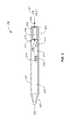
- FIG. 7Ais an illustrative isometric view of an assembled cartridge.
- FIG. 7Bis an illustrative exploded isometric view of a cartridge assembly
- FIG. 7Cis a side section view of FIG. 7A illustrating the inlet channel, inlet hole and relative placement of the wick, resistive heating element, and heater contacts, and the heater chamber inside of the heater.
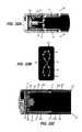
- FIG. 8Ais an illustrative end section view of an exemplary cartridge inside the heater.
- FIG. 8Bis an illustrative side view of the cartridge with the cap removed and heater shown in shadow/outline.
- FIGS. 9A-9Lillustrate an exemplary sequence of one assembly method for a cartridge.
- FIGS. 10A-10Care illustrative sequences showing the airflow/vapor path for the cartridge.
- FIGS. 11, 12, and 13represent an illustrative assembly sequence for assembling the main components of the device.
- FIG. 14illustrates front, side and section views of the assembled inhalable aerosol device.
- FIG. 15is an illustrative view of an activated, assembled inhalable aerosol device.
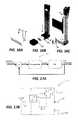
- FIGS. 16A-16Care representative illustrations of a charging device for the aerosol device and the application of the charger with the device.
- FIGS. 17A and 17Bare representative illustrations of a proportional-integral-derivative controller (PID) block diagram and circuit diagram representing the essential components in a device to control coil temperature.
- PIDproportional-integral-derivative controller
- FIG. 17Cis another example of a PID block diagram similar to that of FIG. 17A , in which the resistance of the resistive heater may be used to control the temperature of the apparatuses described herein.
- FIG. 17Dis an example of a circuit showing one variation of the measurement circuit used in the PID block diagram shown in FIG. 17C . Specifically, this is an amplified Wheatstone bridge resistance measurement circuit.
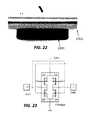
- FIG. 18is a device with charging contacts visible from an exterior housing of the device.
- FIG. 19is an exploded view of a charging assembly of a device.
- FIG. 20is a detailed view of a charging assembly of a device.
- FIG. 21is a detailed view of charging pins in a charging assembly of a device.
- FIG. 22is a device in a charging cradle.
- FIG. 23is a circuit provided on a PCB configured to permit a device to comprise reversible charging contacts.
- the vapormay be delivered for inhalation by a user.
- the materialmay be a solid, liquid, powder, solution, paste, gel, or any a material with any other physical consistency.
- the vapormay be delivered to the user for inhalation by a vaporization device.
- the vaporization devicemay be a handheld vaporization device. The vaporization device may be held in one hand by the user.
- the vaporization devicemay comprise one or more heating elements the heating element may be a resistive heating element.
- the heating elementmay heat the material such that the temperature of the material increases. Vapor may be generated as a result of heating the material.
- Energymay be required to operate the heating element, the energy may be derived from a battery in electrical communication with the heating element. Alternatively a chemical reaction (e.g., combustion or other exothermic reaction) may provide energy to the heating element.
- One or more aspects of the vaporization devicemay be designed and/or controlled in order to deliver a vapor with one or more specified properties to the user.
- aspects of the vaporization device that may be designed and/or controlled to deliver the vapor with specified propertiesmay comprise the heating temperature, heating mechanism, device air inlets, internal volume of the device, and/or composition of the material.
- a vaporization devicemay have an “atomizer” or “cartomizer” configured to heat an aerosol forming solution (e.g., vaporizable material).
- the aerosol forming solutionmay comprise glycerin and/or propylene glycol.
- the vaporizable materialmay be heated to a sufficient temperature such that it may vaporize.
- An atomizermay be a device or system configured to generate an aerosol.
- the atomizermay comprise a small heating element configured to heat and/or vaporize at least a portion of the vaporizable material and a wicking material that may draw a liquid vaporizable material in to the atomizer.
- the wicking materialmay comprise silica fibers, cotton, ceramic, hemp, stainless steel mesh, and/or rope cables.
- the wicking materialmay be configured to draw the liquid vaporizable material in to the atomizer without a pump or other mechanical moving part.
- a resistance wiremay be wrapped around the wicking material and then connected to a positive and negative pole of a current source (e.g., energy source).
- the resistance wiremay be a coil.
- the resistance wireWhen the resistance wire is activated the resistance wire (or coil) may have a temperature increase as a result of the current flowing through the resistive wire to generate heat.
- the heatmay be transferred to at least a portion of the vaporizable material through conductive, convective, and/or radiative heat transfer such that at least a portion of the vaporizable material vaporizes.
- the vaporization devicemay comprise a “cartomizer” to generate an aerosol from the vaporizable material for inhalation by the user.
- the cartomizermay comprise a cartridge and an atomizer.
- the cartomizermay comprise a heating element surrounded by a liquid-soaked poly-foam that acts as holder for the vaporizable material (e.g., the liquid).
- the cartomizermay be reusable, rebuildable, refillable, and/or disposable.
- the cartomizermay be used with a tank for extra storage of a vaporizable material.
- Airmay be drawn into the vaporization device to carry the vaporized aerosol away from the heating element, where it then cools and condenses to form liquid particles suspended in air, which may then be drawn out of the mouthpiece by the user.
- the vaporization of at least a portion of the vaporizable materialmay occur at lower temperatures in the vaporization device compared to temperatures required to generate an inhalable vapor in a cigarette.
- a cigarettemay be a device in which a smokable material is burned to generate an inhalable vapor.
- the lower temperature of the vaporization devicemay result in less decomposition and/or reaction of the vaporized material, and therefore produce an aerosol with many fewer chemical components compared to a cigarette.
- the vaporization devicemay generate an aerosol with fewer chemical components that may be harmful to human health compared to a cigarette.
- the vaporization device aerosol particlesmay undergo nearly complete evaporation in the heating process, the nearly complete evaporation may yield an average particle size (e.g., diameter) value that may be smaller than the average particle size in tobacco or botanical based effluent.
- an average particle sizee.g., diameter
- a vaporization devicemay be a device configured to extract for inhalation one or more active ingredients of plant material, tobacco, and/or a botanical, or other herbs or blends.
- a vaporization devicemay be used with pure chemicals and/or humectants that may or may not be mixed with plant material. Vaporization may be alternative to burning (smoking) that may avoid the inhalation of many irritating and/or toxic carcinogenic by-products which may result from the pyrolytic process of burning tobacco or botanical products above 300° C.
- the vaporization devicemay operate at a temperature at or below 300° C.
- a vaporizermay not have an atomizer or cartomizer. Instead the device may comprise an oven.
- the ovenmay be at least partially closed.
- the ovenmay have a closable opening.
- the ovenmay be wrapped with a heating element, alternatively the heating element may be in thermal communication with the oven through another mechanism.
- a vaporizable materialmay be placed directly in the oven or in a cartridge fitted in the oven.
- the heating element in thermal communication with the ovenmay heat a vaporizable material mass in order to create a gas phase vapor.
- the heating elementmay heat the vaporizable material through conductive, convective, and/or radiative heat transfer.
- the vapormay be released to a vaporization chamber where the gas phase vapor may condense, forming an aerosol cloud having typical liquid vapor particles with particles having a diameter of average mass of approximately 1 micron or greater. In some cases the diameter of average mass may be approximately 0.1-1 micron.
- vapormay generally refer to a substance in the gas phase at a temperature lower than its critical point.
- the vapormay be condensed to a liquid or to a solid by increasing its pressure without reducing the temperature.
- aerosolmay generally refer to a colloid of fine solid particles or liquid droplets in air or another gas.
- aerosolsmay include clouds, haze, and smoke, including the smoke from tobacco or botanical products.
- the liquid or solid particles in an aerosolmay have varying diameters of average mass that may range from monodisperse aerosols, producible in the laboratory, and containing particles of uniform size; to polydisperse colloidal systems, exhibiting a range of particle sizes. As the sizes of these particles become larger, they have a greater settling speed which causes them to settle out of the aerosol faster, making the appearance of the aerosol less dense and to shorten the time in which the aerosol will linger in air.
- humectantmay generally refer to as a substance that is used to keep things moist.
- a humectantmay attract and retain moisture in the air by absorption, allowing the water to be used by other substances.
- Humectantsare also commonly used in many tobaccos or botanicals and electronic vaporization products to keep products moist and as vapor-forming medium. Examples include propylene glycol, sugar polyols such as glycerol, glycerin, and honey.
- the vaporization devicemay be configured to deliver an aerosol with a high particle density.
- the particle density of the aerosolmay refer to the number of the aerosol droplets relative to the volume of air (or other dry gas) between the aerosol droplets.
- a dense aerosolmay easily be visible to a user.
- the usermay inhale the aerosol and at least a fraction of the aerosol particles may impinge on the lungs and/or mouth of the user.
- the usermay exhale residual aerosol after inhaling the aerosol.
- the aerosolis dense the residual aerosol may have sufficient particle density such that the exhaled aerosol is visible to the user.
- a usermay prefer the visual effect and/or mouth feel of a dense aerosol.
- a vaporization devicemay comprise a vaporizable material.
- the vaporizable materialmay be contained in a cartridge or the vaporizable material may be loosely placed in one or more cavities the vaporization device.
- a heating elementmay be provided in the device to elevate the temperature of the vaporizable material such that at least a portion of the vaporizable material forms a vapor.
- the heating elementmay heat the vaporizable material by convective heat transfer, conductive heat transfer, and/or radiative heat transfer.
- the heating elementmay heat the cartridge and/or the cavity in which the vaporizable material is stored.
- Vapor formed upon heating the vaporizable materialmay be delivered to the user.
- the vapormay be transported through the device from a first position in the device to a second position in the device.
- the first positionmay be a location where at least a portion of the vapor was generated, for example, the cartridge or cavity or an area adjacent to the cartridge or cavity.
- the second positionmay be a mouthpiece. The user may suck on the mouthpiece to inhale the vapor.
- At least a fraction of the vapormay condense after the vapor is generated and before the vapor is inhaled by the user.
- the vapormay condense in a condensation chamber.
- the condensation chambermay be a portion of the device that the vapor passes through before delivery to the user.
- the devicemay include at least one aeration vent, placed in the condensation chamber of the vaporization device.
- the aeration ventmay be configured to introduce ambient air (or other gas) into the vaporization chamber.
- the air introduced into the vaporization chambermay have a temperature lower than the temperature of a gas and/or gas/vapor mixture in the condensation chamber.
- Introduction of the relatively lower temperature gas into the vaporization chambermay provide rapid cooling of the heated gas vapor mixture that was generated by heating the vaporizable material. Rapid cooling of the gas vapor mixture may generate a dense aerosol comprising a high concentration of liquid droplets having a smaller diameter and/or smaller average mass compared to an aerosol that is not rapidly cooled prior to inhalation by the user.
- An aerosol with a high concentration of liquid droplets having a smaller diameter and/or smaller average mass compared to an aerosol that is not rapidly cooled prior to inhalation by the usermay be formed in a two-step process.
- the first stepmay occur in the oven chamber where the vaporizable material (e.g., tobacco and/or botanical and humectant blend) may be heated to an elevated temperature.
- the vaporizable materiale.g., tobacco and/or botanical and humectant blend
- the humectantmay continue to evaporate until the partial pressure of the humectant is equal to the saturation pressure.
- the gase.g., vapor and air
- the saturation pressuremay decrease.
- the saturation ratiomay increase and the vapor may begin to condense, forming droplets.
- the coolingmay be relatively slower such that high saturation pressures may not be reached, and the droplets that form in the devices without added cooling aeration may be relatively larger and fewer in numbers.
- the rapid coolingmay generate high saturation ratios, small particles, and high concentrations of smaller particles, forming a thicker, denser vapor cloud compared to particles generated in a device without the aeration vents.
- humectantssuch as vegetable glycerol or propylene glycol
- “about”means a variation of 5%, 10%, 20% or 25% depending on the embodiment.
- a vaporization deviceconfigured to rapidly cool a vapor may comprise: a mouthpiece comprising an aerosol outlet at a first end of the device; an oven comprising an oven chamber and a heater for heating a vapor forming medium in the oven chamber and for forming a vapor therein; a condenser comprising a condensation chamber in which the vapor forms the inhalable aerosol; an air inlet that originates a first airflow path that includes the oven chamber and then the condensation chamber, an aeration vent that originates a second airflow path that joins the first airflow path prior to or within the condensation chamber after the vapor is formed in the oven chamber, wherein the joined first airflow path and second airflow path are configured to deliver the inhalable aerosol formed in the condensation chamber through the aerosol outlet of the mouthpiece to a user.
- the ovenis within a body of the device.
- the oven chambermay comprise an oven chamber inlet and an oven chamber outlet.
- the ovenmay further comprise a first valve at the oven chamber inlet, and a second valve at the oven chamber outlet.
- the ovenmay be contained within a device housing.
- the body of the devicemay comprise the aeration vent and/or the condenser.
- the body of the devicemay comprise one or more air inlets.
- the body of the devicemay comprise a housing that holds and/or at least partially contains one or more elements of the device.
- the mouthpiecemay be connected to the body.
- the mouthpiecemay be connected to the oven.
- the mouthpiecemay be connected to a housing that at least partially encloses the oven. In some cases, the mouthpiece may be separable from the oven, the body, and/or the housing that at least partially encloses the oven.
- the mouthpiecemay comprise at least one of the air inlet, the aeration vent, and the condenser.
- the mouthpiecemay be integral to the body of the device.
- the body of the devicemay comprise the oven.
- the one or more aeration ventsmay comprise a valve.
- the valvemay regulate a flow rate of air entering the device through the aeration vent.
- the valvemay be controlled through a mechanical and/or electrical control system.
- a vaporization device configured to rapidly cool a vapormay comprise: a body, a mouthpiece, an aerosol outlet, a condenser with a condensation chamber, a heater, an oven with an oven chamber, a primary airflow inlet, and at least one aeration vent provided in the body, downstream of the oven, and upstream of the mouthpiece.
- FIG. 1shows an example of a vaporization device configured to rapidly cool a vapor.
- the device 100may comprise a body 101 .
- the bodymay house and/or integrate with one or more components of the device.
- the bodymay house and/or integrate with a mouthpiece 102 .
- the mouthpiece 102may have an aerosol outlet 122 .
- a usermay inhale the generated aerosol through the aerosol outlet 122 on the mouthpiece 102 .
- the bodymay house and/or integrate with an oven region 104 .
- the oven region 104may comprise an oven chamber where vapor forming medium 106 may be placed.
- the vapor forming mediummay include tobacco and/or botanicals, with or without a secondary humectant. In some cases the vapor forming medium may be contained in a removable and/or refillable cartridge.
- Airmay be drawn into the device through a primary air inlet 121 .
- the primary air inlet 121may be on an end of the device 100 opposite the mouthpiece 102 . Alternatively, the primary air inlet 121 may be adjacent to the mouthpiece 102 . In some cases, a pressure drop sufficient to pull air into the device through the primary air inlet 121 may be due to a user puffing on the mouthpiece 102 .
- the vapor forming medium(e.g., vaporizable material) may be heated in the oven chamber by a heater 105 , to generate elevated temperature gas phases (vapor) of the tobacco or botanical and humectant/vapor forming components.
- the heater 105may transfer heat to the vapor forming medium through conductive, convective, and/or radiative heat transfer.
- the generated vapormay be drawn out of the oven region and into the condensation chamber 103 a , of the condenser 103 where the vapors may begin to cool and condense into micro-particles or droplets suspended in air, thus creating the initial formation of an aerosol, before being drawn out of the mouthpiece through the aerosol outlet 122 .
- relatively cooler airmay be introduced into the condensation chamber 103 a , through an aeration vent 107 such that the vapor condenses more rapidly compared to a vapor in a device without the aeration vent 107 .
- Rapidly cooling the vapormay create a denser aerosol cloud having particles with a diameter of average mass of less than or equal to about 1 micron, and depending on the mixture ratio of the vapor-forming humectant, particles with a diameter of average mass of less than or equal to about 0.5 micron
- Also described herein are devices for generating an inhalable aerosol said devicecomprising a body with a mouthpiece at one end, an attached body at the other end comprising a condensation chamber, a heater, an oven, wherein the oven comprises a first valve in the airflow path at the primary airflow inlet of the oven chamber, and a second valve at the outlet end of the oven chamber, and at least one aeration vent provided in the body, downstream of the oven, and upstream of the mouthpiece.
- FIG. 2shows a diagram of an alternative embodiment of the vaporization device 200 .
- the vaporization devicemay have a body 201 .
- the body 201may integrate with and/or contain one or more components of the device.
- the bodymay integrate with or be connected to a mouthpiece 202
- the bodymay comprise an oven region 204 , with an oven chamber 204 a having a first constricting valve 208 in the primary air inlet of the oven chamber and a second constricting valve 209 at the oven chamber outlet.
- the oven chamber 204 amay be sealed with a tobacco or botanical and/or humectant/vapor forming medium 206 therein.
- the sealmay be an air tight and/or liquid tight seal.
- the heatermay be provided to the oven chamber with a heater 205 .
- the heater 205may be in thermal communication with the oven, for example the heater may be surrounding the oven chamber during the vaporization process. Heater may contact the oven.
- the heatermay be wrapped around the oven.
- pressuremay build in the sealed oven chamber as heat is continually added.
- the pressuremay build due to a phase change of the vaporizable material.
- Elevated temperature gas phases (vapor) of the tobacco or botanical and humectant/vapor forming componentsmay be achieved by continually adding heat to the oven.
- This heated pressurization processmay generate even higher saturation ratios when the valves 208 , 209 are opened during inhalation. The higher saturation ratios may cause relatively higher particle concentrations of gas phase humectant in the resultant aerosol.
- the gas phase humectant vaporsmay be exposed to additional air through an aeration vent 207 , and the vapors may begin to cool and condense into droplets suspended in air.
- the aerosolmay be drawn through the mouthpiece 222 by the user.
- This condensation processmay be further refined by adding an additional valve 210 , to the aeration vent 207 to further control the air-vapor mixture process.
- FIG. 2also illustrates an exemplary embodiment of the additional components which would be found in a vaporizing device, including a power source or battery 211 , a printed circuit board 212 , a temperature regulator 213 , and operational switches (not shown), housed within an internal electronics housing 214 , to isolate them from the damaging effects of the moisture in the vapor and/or aerosol.
- the additional componentsmay be found in a vaporizing device that may or may not comprise an aeration vent as described above.
- components of the deviceare user serviceable, such as the power source or battery. These components may be replaceable or rechargeable.
- Also described herein are devices for generating an inhalable aerosol said devicecomprising a first body, a mouthpiece having an aerosol outlet, a condensation chamber within a condenser and an airflow inlet and channel, an attached second body, comprising a heater and oven with an oven chamber, wherein said airflow channel is upstream of the oven and the mouthpiece outlet to provide airflow through the device, across the oven, and into the condensation chamber where an auxiliary aeration vent is provided.
- FIG. 3shows a section view of a vaporization device 300 .
- the device 300may comprise a body 301 .
- the bodymay be connected to or integral with a mouthpiece 302 at one end.
- the mouthpiecemay comprise a condensation chamber 303 a within a condenser section 303 and an airflow inlet 321 and air channel 323 .
- the device bodymay comprise a proximally located oven 304 comprising an oven chamber 304 a .
- the oven chambermay be in the body of the device.
- a vapor forming medium 306(e.g., vaporizable material) comprising tobacco or botanical and humectant vapor forming medium may be placed in the oven.
- the vapor forming mediummay be in direct contact with an air channel 323 from the mouthpiece.
- the tobacco or botanicalmay be heated by heater 305 surrounding the oven chamber, to generate elevated temperature gas phases (vapor) of the tobacco or botanical and humectant/vapor forming components and air drawn in through a primary air inlet 321 , across the oven, and into the condensation chamber 303 a of the condenser region 303 due to a user puffing on the mouthpiece.
- heater 305surrounding the oven chamber, to generate elevated temperature gas phases (vapor) of the tobacco or botanical and humectant/vapor forming components and air drawn in through a primary air inlet 321 , across the oven, and into the condensation chamber 303 a of the condenser region 303 due to a user puffing on the mouthpiece.
- the devicemay comprises a mouthpiece comprising an aerosol outlet at a first end of the device and an air inlet that originates a first airflow path; an oven comprising an oven chamber that is in the first airflow path and includes the oven chamber and a heater for heating a vapor forming medium in the oven chamber and for forming a vapor therein, a condenser comprising a condensation chamber in which the vapor forms the inhalable aerosol, an aeration vent that originates a second airflow path that allows air from the aeration vent to join the first airflow path prior to or within the condensation chamber and downstream from the oven chamber thereby forming a joined path, wherein the joined path is configured to deliver the inhalable aerosol formed in the condensation chamber through the aerosol outlet of the mouthpiece to a user.
- the devicemay comprise a mouthpiece comprising an aerosol outlet at a first end of the device, an air inlet that originates a first airflow path, and an aeration vent that originates a second airflow path that allows air from the aeration vent to join the first airflow path; an oven comprising an oven chamber that is in the first airflow path and includes the oven chamber and a heater for heating a vapor forming medium in the oven chamber and for forming a vapor therein, a condenser comprising a condensation chamber in which the vapor forms the inhalable aerosol and wherein air from the aeration vent joins the first airflow path prior to or within the condensation chamber and downstream from the oven chamber thereby forming a joined path, wherein the joined path is configured to deliver the inhalable aerosol through the aerosol outlet of the mouthpiece to a user, as illustrated in exemplary FIG. 3 .
- the devicemay comprise a body with one or more separable components.
- the mouthpiecemay be separably attached to the body comprising the condensation chamber, a heater, and an oven, as illustrated in exemplary FIG. 1 or 2 .
- the devicemay comprise a body with one or more separable components.
- the mouthpiecemay be separably attached to the body.
- the mouthpiecemay comprise the condensation chamber, and may be attached to or immediately adjacent to the oven and which is separable from the body comprising a heater, and the oven, as illustrated in exemplary FIG. 3 .
- the at least one aeration ventmay be located in the condensation chamber of the condenser, as illustrated in exemplary FIG. 1, 2 , or 3 .
- the at least one aeration ventmay comprise a third valve in the airflow path of the at least one aeration vent, as illustrated in exemplary FIG. 2 .
- the first, second and third valveis a check valve, a clack valve, a non-return valve, or a one-way valve. In any of the preceding variations, the first, second or third valve may be mechanically actuated, electronically actuated or manually actuated.
- this devicemay be modified in a way such that any one, or each of these openings or vents could be configured to have a different combination or variation of mechanisms as described to control airflow, pressure and temperature of the vapor created and aerosol being generated by these device configurations, including a manually operated opening or vent with or without a valve.
- the devicemay further comprise at least one of: a power source, a printed circuit board, a switch, and a temperature regulator. Alternately, one skilled in the art would recognize that each configuration previously described will also accommodate said power source (battery), switch, printed circuit board, or temperature regulator as appropriate, in the body.
- the devicemay be disposable when the supply of pre-packaged aerosol-forming media is exhausted.
- the devicemay be rechargeable such that the battery may be rechargeable or replaceable, and/or the aerosol-forming media may be refilled, by the user/operator of the device.
- the devicemay be rechargeable such that the battery may be rechargeable or replaceable, and/or the operator may also add or refill a tobacco or botanical component, in addition to a refillable or replaceable aerosol-forming media to the device.
- the vaporization devicemay comprise tobacco or a botanical heated in said oven chamber, wherein said tobacco or botanical further comprises humectants to produce an aerosol comprising gas phase components of the humectant and tobacco or botanical.
- the gas phase humectant and tobacco or botanical vapor produced by said heated aerosol forming media 106 , 206 , 306may further be mixed with air from a special aeration vent 107 , 207 , 307 after exiting the oven area 104 , 204 , 304 and entering a condensation chamber 103 a , 203 a , 303 a to cool and condense said gas phase vapors to produce a far denser, thicker aerosol comprising more particles than would have otherwise been produced without the extra cooling air, with a diameter of average mass of less than or equal to about 1 micron.
- Each aerosol configuration produced by mixing the gas phase vapors with the cool airmay comprise a different range of particles, for example; with a diameter of average mass of less than or equal to about 0.9 micron; less than or equal to about 0.8 micron; less than or equal to about 0.7 micron; less than or equal to about 0.6 micron; and even an aerosol comprising particle diameters of average mass of less than or equal to about 0.5 micron.
- the humectantmay comprise glycerol or vegetable glycerol as a vapor-forming medium.
- the humectantmay comprise propylene glycol as a vapor-forming medium.
- the humectantmay comprise a ratio of vegetable glycerol to propylene glycol as a vapor-forming medium.
- the ranges of said ratiomay vary between a ratio of about 100:0 vegetable glycerol to propylene glycol and a ratio of about 50:50 vegetable glycerol to propylene glycol.
- the difference in preferred ratios within the above stated rangemay vary by as little as 1, for example, said ratio may be about 99:1 vegetable glycerol to propylene glycol.
- ratioswould vary in increments of about 5, for example, about 95:5 vegetable glycerol to propylene glycol; or about 85:15 vegetable glycerol to propylene glycol; or about 55:45 vegetable glycerol to propylene glycol.
- the ratio for the vapor forming mediumwill be between the ratios of about 80:20 vegetable glycerol to propylene glycol, and about 60:40 vegetable glycerol to propylene glycol.
- the ratio for the vapor forming mediumwill be about 70:30 vegetable glycerol to propylene glycol.
- the humectantmay further comprise flavoring products.
- flavoringsmay include enhancers comprising cocoa solids, licorice, tobacco or botanical extracts, and various sugars, to name but a few.
- the tobacco or botanicalmay be heated in the oven up to its pyrolytic temperature, which as noted previously is most commonly measured in the range of 300-1000° C.
- the tobacco or botanicalis heated to about 300° C. at most. In other preferred embodiments, the tobacco or botanical is heated to about 200° C. at most. In still other preferred embodiments, the tobacco or botanical is heated to about 160° C. at most. It should be noted that in these lower temperature ranges ( ⁇ 300° C.), pyrolysis of tobacco or botanical does not typically occur, yet vapor formation of the tobacco or botanical components and flavoring products does occur. In addition, vapor formation of the components of the humectant, mixed at various ratios will also occur, resulting in nearly complete vaporization, depending on the temperature, since propylene glycol has a boiling point of about 180°-190° C. and vegetable glycerin will boil at approximately 280°-290° C.
- the aerosol produced by said heated tobacco or botanical and humectantis mixed with air provided through an aeration vent.
- the aerosol produced by said heated tobacco or botanical and humectant mixed with airis cooled to a temperature of about 50°-70° C. at most, and even as low as 35° C. before exiting the mouthpiece, depending on the air temperature being mixed into the condensation chamber.
- the temperatureis cooled to about 35°-55° C. at most, and may have a fluctuating range of ⁇ about 10° C. or more within the overall range of about 35°-70° C.
- vaporization devices for generating an inhalable aerosolcomprising a unique oven configuration, wherein said oven comprises an access lid and an auxiliary aeration vent located within the airflow channel immediately downstream of the oven and before the aeration chamber.
- said ovencomprises an access lid and an auxiliary aeration vent located within the airflow channel immediately downstream of the oven and before the aeration chamber.
- the usermay directly access the oven by removing the access lid, providing the user with the ability to recharge the device with vaporization material.
- having the added aeration vent in the airflow channel immediately after the oven and ahead of the vaporization chamberprovides the user with added control over the amount of air entering the aeration chamber downstream and the cooling rate of the aerosol before it enters the aeration chamber.
- the device 400may comprise a body 401 , having an air inlet 421 allowing initial air for the heating process into the oven region 404 .
- the gas phase humectant vapor generatedmay travel down the airflow channel 423 , passing the added aeration vent 407 wherein the user may selectively increase airflow into the heated vapor.
- the usermay selectively increase and/or decrease the airflow to the heated vapor by controlling a valve in communication with the aeration vent 407 .
- the devicemay not have an aeration vent.
- Airflow into the heated vapor through the aeration ventmay decrease the vapor temperature before exiting the airflow channel at the outlet 422 , and increase the condensation rate and vapor density by decreasing the diameter of the vapor particles within the aeration chamber (not shown), thus producing a thicker, denser vapor compared to the vapor generated by a device without the aeration vent.
- the usermay also access the oven chamber 404 a to recharge or reload the device 400 , through an access lid 430 provided therein, making the device user serviceable.
- the access lidmay be provided on a device with or without an aeration vent.
- a method for generating an inhalable aerosolcomprising: providing an vaporization device, wherein said device produces a vapor comprising particle diameters of average mass of about 1 micron or less, wherein the vapor is formed by heating a vapor forming medium in an oven chamber of the device to a first temperature below the pyrolytic temperature of the vapor forming medium, and cooling the vapor in a condensation chamber to a temperature below the first temperature, before exiting an aerosol outlet of said device.
- the vapormay be cooled by mixing relatively cooler air with the vapor in the condensation chamber during the condensation phase, after leaving the oven, where condensation of the gas phase humectants occurs more rapidly due to high saturation ratios being achieved at the moment of aeration, producing a higher concentration of smaller particles, with fewer by-products, in a denser aerosol, than would normally occur in a standard vaporization or aerosol generating device.
- formation of an inhalable aerosolis a two-step process.
- the gasleaves the oven chamber, passes to a condensation chamber in a condenser and begins to cool.
- the saturation pressurealso goes down, causing the saturation ratio to rise, and the vapor to condensate, forming droplets.
- cooling airis introduced, the large temperature gradient between the two fluids mixing in a confined space leads to very rapid cooling, causing high saturation ratios, small particles, and higher concentrations of smaller particles, forming a thicker, denser vapor cloud.
- a method for generating an inhalable aerosolcomprising: a vaporization device having a body with a mouthpiece at one end, and an attached body at the other end comprising; a condenser with a condensation chamber, a heater, an oven with an oven chamber, and at least one aeration vent provided in the body, downstream of the oven, and upstream of the mouthpiece, wherein tobacco or botanical comprising a humectant is heated in said oven chamber to produce a vapor comprising gas phase humectants.
- a vaporization devicehaving an auxiliary aeration vent located in the condensation chamber capable of supplying cool air (relative to the heated gas components) to the gas phase vapors and tobacco or botanical components exiting the oven region, may be utilized to provide a method for generating a far denser, thicker aerosol comprising more particles than would have otherwise been produced without the extra cooling air, with a diameter of average mass of less than or equal to about 1 micron.
- a method for generating an inhalable aerosolcomprising: a vaporization device, having a body with a mouthpiece at one end, and an attached body at the other end comprising: a condenser with a condensation chamber, a heater, an oven with an oven chamber, wherein said oven chamber further comprises a first valve in the airflow path at the inlet end of the oven chamber, and a second valve at the outlet end of the oven chamber; and at least one aeration vent provided in said body, downstream of the oven, and upstream of the mouthpiece wherein tobacco or botanical comprising a humectant is heated in said oven chamber to produce a vapor comprising gas phase humectants.
- the pressurewill build in the oven chamber as heat is continually added with an electronic heating circuit generated through the combination of the battery 211 , printed circuit board 212 , temperature regulator 213 , and operator controlled switches (not shown), to generate even greater elevated temperature gas phase humectants (vapor) of the tobacco or botanical and humectant vapor forming components.
- This heated pressurization processgenerates even higher saturation ratios when the valves 208 , 209 are opened during inhalation, which cause higher particle concentrations in the resultant aerosol, when the vapor is drawn out of the oven region and into the condensation chamber 203 a , where they are again exposed to additional air through an aeration vent 207 , and the vapors begin to cool and condense into droplets suspended in air, as described previously before the aerosol is withdrawn through the mouthpiece 222 .
- the inventoralso notes that this condensation process may be further refined by adding an additional valve 210 , to the aeration vent 207 to further control the air-vapor mixture process.
- the first, second and/or third valveis a one-way valve, a check valve, a clack valve, or a non-return valve.
- the first, second and/or third valvemay be mechanically actuated.
- the first, second and/or third valvemay be electronically actuated.
- the first, second and/or third valvemay be automatically actuated.
- the first, second and/or third valvemay be manually actuated either directly by a user or indirectly in response to an input command from a user to a control system that actuates the first, second and/or third valve.
- said devicefurther comprises at least one of: a power source, a printed circuit board, or a temperature regulator.
- any one, or each of these openings or ventscould be configured to have a different combination or variation of mechanisms or electronics as described to control airflow, pressure and temperature of the vapor created and aerosol being generated by these device configurations, including a manually operated opening or vent with or without a valve.
- the humectantcomprises a ratio of vegetable glycerol to propylene glycol as a vapor-forming medium.
- the ranges of said ratiowill vary between a ratio of about 100:0 vegetable glycerol to propylene glycol and a ratio of about 50:50 vegetable glycerol to propylene glycol.
- the difference in preferred ratios within the above stated rangemay vary by as little as 1, for example, said ratio may be about 99:1 vegetable glycerol to propylene glycol.
- ratioswould vary in increments of 5, for example, about 95:5 vegetable glycerol to propylene glycol; or about 85:15 vegetable glycerol to propylene glycol; or about 55:45 vegetable glycerol to propylene glycol.
- the ratio for the vapor forming mediumwill be between the ratios of about 80:20 vegetable glycerol to propylene glycol, and about 60:40 vegetable glycerol to propylene glycol.
- the ratio for the vapor forming mediumwill be about 70:30 vegetable glycerol to propylene glycol.
- the ratio for the vapor forming mediumwill be about 70:30 vegetable glycerol to propylene glycol.
- the humectantfurther comprises flavoring products.
- flavoringsinclude enhancers such as cocoa solids, licorice, tobacco or botanical extracts, and various sugars, to name a few.
- the tobacco or botanicalis heated to its pyrolytic temperature.
- the tobacco or botanicalis heated to about 300° C. at most.
- the tobacco or botanicalis heated to about 200° C. at most. In still other embodiments of the method, the tobacco or botanical is heated to about 160° C. at most.
- said inhalable aerosol produced by tobacco or a botanical comprising a humectant and heated in said ovenproduces an aerosol comprising gas phase humectants is further mixed with air provided through an aeration vent.
- said aerosol produced by said heated tobacco or botanical and humectant mixed with airis cooled to a temperature of about 50°-70° C., and even as low as 35° C., before exiting the mouthpiece.
- the temperatureis cooled to about 35°-55° C. at most, and may have a fluctuating range of ⁇ about 10° C. or more within the overall range of about 35°-70° C.
- the vapor comprising gas phase humectantmay be mixed with air to produce an aerosol comprising particle diameters of average mass of less than or equal to about 1 micron.
- each aerosol configuration produced by mixing the gas phase vapors with the cool airmay comprise a different range of particles, for example; with a diameter of average mass of less than or equal to about 0.9 micron; less than or equal to about 0.8 micron; less than or equal to about 0.7 micron; less than or equal to about 0.6 micron; and even an aerosol comprising particle diameters of average mass of less than or equal to about 0.5 micron.
- a vaporization devicemay be configured to generate an inhalable aerosol.
- a devicemay be a self-contained vaporization device.
- the devicemay comprise an elongated body which functions to complement aspects of a separable and recyclable cartridge with air inlet channels, air passages, multiple condensation chambers, flexible heater contacts, and multiple aerosol outlets. Additionally, the cartridge may be configured for ease of manufacture and assembly.
- the devicemay comprise a device body, a separable cartridge assembly further comprising a heater, at least one condensation chamber, and a mouthpiece.
- the deviceprovides for compact assembly and disassembly of components with detachable couplings; overheat shut-off protection for the resistive heating element; an air inlet passage (an enclosed channel) formed by the assembly of the device body and a separable cartridge; at least one condensation chamber within the separable cartridge assembly; heater contacts; and one or more refillable, reusable, and/or recyclable components.
- a device for generating an inhalable aerosolcomprising: a device body comprising a cartridge receptacle; a cartridge comprising: a storage compartment, and a channel integral to an exterior surface of the cartridge, and an air inlet passage formed by the channel and an internal surface of the cartridge receptacle when the cartridge is inserted into the cartridge receptacle.
- the cartridgemay be formed from a metal, plastic, ceramic, and/or composite material.
- the storage compartmentmay hold a vaporizable material.
- FIG. 7Ashows an example of a cartridge 30 for use in the device.
- the vaporizable materialmay be a liquid at or near room temperature. In some cases the vaporizable material may be a liquid below room temperature.
- the channelmay form a first side of the air inlet passage, and an internal surface of the cartridge receptacle may form a second side of the air inlet passage, as illustrated in various non-limiting aspects of FIGS. 5-6D, 7C,8A, 8B, and 10A
- the devicemay comprise a body that houses, contains, and or integrates with one or more components of the device.
- the device bodymay comprise a cartridge receptacle.
- the cartridge receptaclemay comprise a channel integral to an interior surface of the cartridge receptacle; and an air inlet passage formed by the channel and an external surface of the cartridge when the cartridge is inserted into the cartridge receptacle.
- a cartridgemay be fitted and/or inserted into the cartridge receptacle.
- the cartridgemay have a fluid storage compartment.
- the channelmay form a first side of the air inlet passage, and an external surface of the cartridge forms a second side of the air inlet passage.
- the channelmay comprise at least one of: a groove; a trough; a track; a depression; a dent; a furrow; a trench; a crease; and a gutter.
- the integral channelmay comprise walls that are either recessed into the surface or protrude from the surface where it is formed.
- the internal side walls of the channelmay form additional sides of the air inlet passage.
- the channelmay have a round, oval, square, rectangular, or other shaped cross section.
- the channelmay have a closed cross section.
- the channelmay be about 0.1 cm, 0.5 cm, 1 cm, 2 cm, or 5 cm wide.
- the channelmay be about 0.1 mm, 0.5 mm, 1 mm, 2 mm, or 5 mm deep.
- the channelmay be about 0.1 cm, 0.5 cm, 1 cm, 2 cm, or 5 cm long. There may be at least 1 channel.
- the cartridgemay further comprise a second air passage in fluid communication with the air inlet passage to the fluid storage compartment, wherein the second air passage is formed through the material of the cartridge.
- FIGS. 5-7Cshow various views of a compact electronic device assembly 10 for generating an inhalable aerosol.
- the compact electronic device 10may comprise a device body 20 with a cartridge receptacle 21 for receiving a cartridge 30 .
- the device bodymay have a square or rectangular cross section. Alternatively, the cross section of the body may be any other regular or irregular shape.
- the cartridge receptaclemay be shaped to receive an opened cartridge 30 a or “pod”.
- the cartridgemay be opened when a protective cap is removed from a surface of the cartridge. In some cases, the cartridge may be opened when a hole or opening is formed on a surface of the cartridge.
- the pod 30 amay be inserted into an open end of the cartridge receptacle 21 so that an exposed first heater contact tips 33 a on the heater contacts 33 of the pod make contact with the second heater contacts 22 of the device body, thus forming the device assembly 10 .
- the channel air inlet 50is left exposed.
- the size of the channel air inlet 50may be varied by altering the configuration of the notch in the cartridge receptacle 21 .
- the device bodymay further comprise a rechargeable battery, a printed circuit board (PCB) 24 containing a microcontroller with the operating logic and software instructions for the device, a pressure switch 27 for sensing the user's puffing action to activate the heater circuit, an indicator light 26 , charging contacts (not shown), and an optional charging magnet or magnetic contact (not shown).
- the cartridgemay further comprise a heater 36 .
- the heatermay be powered by the rechargeable battery.
- the temperature of the heatermay be controlled by the microcontroller.
- the heatermay be attached to a first end of the cartridge.
- the heatermay comprise a heater chamber 37 , a first pair of heater contacts 33 , 33 ′, a fluid wick 34 , and a resistive heating element 35 in contact with the wick.
- the first pair of heater contactsmay comprise thin plates affixed about the sides of the heater chamber.
- the fluid wick and resistive heating elementmay be suspended between the heater contacts.
- the heater contact 33may comprise: a flat plate; a male contact; a female receptacle, or both; a flexible contact and/or copper alloy or another electrically conductive material.
- the first pair of heater contactsmay further comprise a formed shape that may comprise a tab (e.g., flange) having a flexible spring value that extends out of the heater to complete a circuit with the device body.
- the first pair of heater contactmay be a heat sink that absorb and dissipate excessive heat produced by the resistive heating element.
- the first pair of heater contactsmay be a heat shield that protects the heater chamber from excessive heat produced by the resistive heating element.
- the first pair of heater contactsmay be press-fit to an attachment feature on the exterior wall of the first end of the cartridge.
- the heatermay enclose a first end of the cartridge and a first end of the fluid storage compartment.
- a heater enclosuremay comprises two or more heater contacts 33 , each comprising a flat plate which may be machined or stamped from a copper alloy or similar electrically conductive material.
- the flexibility of the tipis provided by the cut-away clearance feature 33 b created below the male contact point tip 33 a which capitalizes on the inherent spring capacity of the metal sheet or plate material.
- Another advantage and improvement of this type of contactis the reduced space requirement, simplified construction of a spring contact point (versus a pogo pin) and the easy of assembly.
- the heatermay comprise a first condensation chamber.
- the heatermay comprise more one or more additional condensation chambers in addition to the first condensation chamber.
- the first condensation chambermay be formed along an exterior wall of the cartridge.
- the cartridge(e.g., pod) is configured for ease of manufacturing and assembly.
- the cartridgemay comprise an enclosure.
- the enclosuremay be a tank.
- the tankmay comprise an interior fluid storage compartment 32 .
- the interior fluid storage compartment 32which is open at one or both ends and comprises raised rails on the side edges 45 b and 46 b .
- the cartridgemay be formed from plastic, metal, composite, and/or a ceramic material.
- the cartridgemay be rigid or flexible.
- the tankmay further comprise a set of first heater contact plates 33 formed from copper alloy or another electrically conductive material, having a thin cut-out 33 b below the contact tips 33 a (to create a flexible tab) which are affixed to the sides of the first end of the tank and straddle the open-sided end 53 of the tank.
- the platesmay affix to pins, or posts as shown in FIG. 7B or 5 , or may be attached by other common means such as compression beneath the enclosure 36 .
- a fluid wick 34having a resistive heating element 35 wrapped around it, is placed between the first heater contact plates 33 , and attached thereto.
- a heater 36comprising raised internal edges on the internal end (not shown), a thin mixing zone (not shown), and primary condensation channel covers 45 a that slide over the rails 45 b on the sides of the tank on the first half of the tank, creating a primary condensation channel/chamber 45 .
- a small male snap feature 39 b located at the end of the channel coveris configured fall into a female snap feature 39 a , located mid-body on the side of the tank, creating a snap-fit assembly.
- the primary condensation channel covers 45 awhich slide over the rails 45 b on the sides of the tank create an integrated, easily assembled, primary condensation chamber 45 , all within the heater at the first end of the cartridge 30 or pod 30 a.
- the heatermay encloses at least a first end of the cartridge.
- the enclosed first end of the cartridgemay include the heater and the interior fluid storage compartment.
- the heaterfurther comprises at least one first condensation chamber 45 .
- FIGS. 9A-9Lshow diagramed steps that mat be performed to assemble a cartomizer and/or mouthpiece.
- the fluid storage compartment 32 amay be oriented such that the heater inlet 53 faces upward.
- the heater contacts 33may be inserted into the fluid storage compartment.
- Flexible tabs 33 amay be inserted into the heater contacts 33 .
- the resistive heating element 35may be wound on to the wick 34 .
- the wick 34 and heater 35may be placed on the fluid storage compartment.
- One or more free ends of the heatermay sit outside the heater contacts. The one or more free ends may be soldered in place, rested in a groove, or snapped into a fitted location.
- At least a fraction of the one or more free endsmay be in communication with the heater contacts 33 .
- the heater enclosure 36may be snapped in place.
- the heater enclosure 36may be fitted on the fluid storage compartment.
- FIG. 9Gshows the heater enclosure 36 is in place on the fluid storage compartment.
- the fluid storage compartmentcan be flipped over.
- FIG. 9Ithe mouthpiece 31 can be fitted on the fluid storage compartment.
- FIG. 9Jshows the mouthpiece 31 in place on the fluid storage compartment.
- an end 49can be fitted on the fluid storage compartment opposite the mouthpiece.
- FIG. 9Lshows a fully assembled cartridge 30 .
- FIG. 7Bshows an exploded view of the assembled cartridge 30 .
- the heatermay have more than one wick 34 and resistive heating element 35 .
- the first pair of heater contacts 33further comprises a formed shape that comprises a tab 33 a having a flexible spring value that extends out of the heater.
- the cartridge 30comprises heater contacts 33 which are inserted into the cartridge receptacle 21 of the device body 20 wherein, the flexible tabs 33 a insert into a second pair of heater contacts 22 to complete a circuit with the device body.
- the first pair of heater contacts 33may be a heat sink that absorbs and dissipates excessive heat produced by the resistive heating element 35 .
- the first pair of heater contacts 33may be a heat shield that protects the heater chamber from excessive heat produced by the resistive heating element 35 .
- the first pair of heater contactsmay be press-fit to an attachment feature on the exterior wall of the first end of the cartridge.
- the heater 36may enclose a first end of the cartridge and a first end of the fluid storage compartment 32 a .
- the heatermay comprise a first condensation chamber 45 .
- the heatermay comprise at least one additional condensation chamber 45 , 45 ′, 45 ′′, etc.
- the first condensation chambermay be formed along an exterior wall of the cartridge.
- the cartridgemay further comprise a mouthpiece 31 , wherein the mouthpiece comprises at least one aerosol outlet channel/secondary condensation chamber 46 ; and at least one aerosol outlet 47 .
- the mouthpiecemay be attached to a second end of the cartridge. The second end of the cartridge with the mouthpiece may be exposed when the cartridge is inserted in the device.
- the mouthpiecemay comprise more than one second condensation chamber 46 , 46 ′, 46 ′′, etc.
- the second condensation chamberis formed along an exterior wall of the cartridge.
- the mouthpiece 31may enclose the second end of the cartridge and interior fluid storage compartment.
- the partially assembled (e.g., mouthpiece removed) unitmay be inverted and filled with a vaporizable fluid through the opposite, remaining (second) open end.
- a snap-on mouthpiece 31that also closes and seals the second end of the tank is inserted over the end. It also comprises raised internal edges (not shown), and aerosol outlet channel covers 46 a that may slide over the rails 46 b located on the sides of the second half of the tank, creating aerosol outlet channels/secondary condensation chambers 46 .
- the aerosol outlet channels/secondary condensation chambers 46slide over the end of primary condensation chamber 45 , at a transition area 57 , to create a junction for the vapor leaving the primary chamber and proceed out through the aerosol outlets 47 , at the end of the aerosol outlet channels 46 and user-end of the mouthpiece 31 .
- the cartridgemay comprise a first condensation chamber and a second condensation chamber 45 , 46 .
- the cartridgemay comprise more than one first condensation chamber and more than one second condensation chamber 45 , 46 , 45 ′, 46 ′, etc.
- a first condensation chamber 45may be formed along the outside of the cartridge fluid storage compartment 31 .
- an aerosol outlet 47exists at the end of aerosol outlet chamber 46 .
- a first and second condensation chamber 45 , 46may be formed along the outside of one side of the cartridge fluid storage compartment 31 .
- the second condensation chambermay be an aerosol outlet chamber.
- another pair of first and/or second condensation chambers 45 ′, 46 ′is formed along the outside of the cartridge fluid storage compartment 31 on another side of the device.
- another aerosol outlet 47 ′will also exist at the end of the second pair of condensation chambers 45 ′, 46 ′.
- the first condensation chamber and the second condensation chambermay be in fluid communication as illustrated in FIG. 10C .
- the mouthpiecemay comprise an aerosol outlet 47 in fluid communication with the second condensation chamber 46 .
- the mouthpiecemay comprise more than one aerosol outlet 47 , 47 ′ in fluid communication with more than one the second condensation chamber 46 , 46 ′.
- the mouthpiecemay enclose a second end of the cartridge and a second end of the fluid storage compartment.
- the cartridgemay comprise an airflow path comprising: an air inlet passage; a heater; at least a first condensation chamber; an aerosol outlet chamber, and an outlet port.
- the cartridgecomprises an airflow path comprising: an air inlet passage; a heater; a first condensation chamber; a secondary condensation chamber; and an outlet port.
- the cartridgemay comprise an airflow path comprising at least one air inlet passage; a heater; at least one first condensation chamber; at least one secondary condensation chamber; and at least one outlet port.
- an airflow pathis created when the user draws on the mouthpiece 31 to create a suction (e.g., a puff), which essentially pulls air through the channel air inlet opening 50 , through the air inlet passage 51 , and into the heater chamber 37 through the second air passage (tank air inlet hole) 41 at the tank air inlet 52 , then into the heater inlet 53 .
- a suctione.g., a puff
- the pressure sensorhas sensed the user's puff, and activated the circuit to the resistive heating element 35 , which in turn, begins to generate vapor from the vapor fluid (e-juice).
- FIG. 8Ashows a detailed view of the sealing structure obstacles 44 .
- the vapormay be drawn, out of the heater along an air path 55 near the shoulder of the heater and into the primary condensation chamber 45 where the vapor expands and begins to cool.
- the expanding vapormoves along the airflow path, it makes a transition from the primary condensation chamber 45 through a transition area 57 , creating a junction for the vapor leaving the primary chamber, and entering the second vapor chamber 46 , and proceeds out through the aerosol outlets 47 , at the end of the mouthpiece 31 to the user.
- the devicemay have a dual set of air inlet passages 50 - 53 , dual first condensation chambers 55 / 45 , dual second condensation chambers and aeration channels 57 / 46 , and/or dual aerosol outlet vents 47 .
- the devicemay have an airflow path comprising: an air inlet passage 50 , 51 ; a second air passage 41 ; a heater chamber 37 ; a first condensation chamber 45 ; a second condensation chamber 46 ; and/or an aerosol outlet 47 .
- the devisemay have an airflow path comprising: more than one air inlet passage; more than one second air passage; a heater chamber; more than one first condensation chamber; more than one second condensation chamber; and more than one aerosol outlet as clearly illustrated in FIGS. 10A-10C .
- the heater 36may be in fluid communication with the internal fluid storage compartment 32 a.
- the fluid storage compartment 32is in fluid communication with the heater chamber 37 , wherein the fluid storage compartment is capable of retaining condensed aerosol fluid, as illustrated in FIGS. 10A, 10C and 14 .
- the condensed aerosol fluidmay comprise a nicotine formulation. In some embodiments, the condensed aerosol fluid may comprise a humectant. In some embodiments, the humectant may comprise propylene glycol. In some embodiments, the humectant may comprise vegetable glycerin.
- the cartridgemay be detachable from the device body.
- the cartridge receptacle and the detachable cartridgemay form a separable coupling.
- the separable couplingmay comprise a friction assembly.
- the devicemay have a press-fit (friction) assembly between the cartridge pod 30 a and the device receptacle.
- a dent/friction capturesuch as 43 may be utilized to capture the pod 30 a to the device receptacle or to hold a protective cap 38 on the pod, as further illustrated in FIG. 8B .
- the separable couplingmay comprise a snap-fit or snap-lock assembly. In still other embodiments the separable coupling may comprise a magnetic assembly.
- the cartridge componentsmay comprise a snap-fit or snap-lock assembly, as illustrated in FIG. 5 .
- the cartridge componentsmay be reusable, refillable, and/or recyclable. The design of these cartridge components lend themselves to the use of such recyclable plastic materials as polypropylene, for the majority of components.
- the cartridge 30may comprise: a fluid storage compartment 32 ; a heater 36 affixed to a first end with a snap-fit coupling 39 a , 39 b ; and a mouthpiece 31 affixed to a second end with a snap-fit coupling 39 c , 39 d (not shown—but similar to 39 a and 39 b ).
- the heater 36may be in fluid communication with the fluid storage compartment 32 .
- the fluid storage compartmentmay be capable of retaining condensed aerosol fluid.
- the condensed aerosol fluidmay comprise a nicotine formulation.
- the condensed aerosol fluidmay comprise a humectant.
- the humectantmay comprise propylene glycol and/or vegetable glycerin.
- a device for generating an inhalable aerosolcomprising: a device body 20 comprising a cartridge receptacle 21 for receiving a cartridge 30 ; wherein an interior surface of the cartridge receptacle forms a first side of an air inlet passage 51 when a cartridge comprising a channel integral 40 to an exterior surface is inserted into the cartridge receptacle 21 , and wherein the channel forms a second side of the air inlet passage 51 .
- a device for generating an inhalable aerosolcomprising: a device body 20 comprising a cartridge receptacle 21 for receiving a cartridge 30 ; wherein the cartridge receptacle comprises a channel integral to an interior surface and forms a first side of an air inlet passage when a cartridge is inserted into the cartridge receptacle, and wherein an exterior surface of the cartridge forms a second side of the air inlet passage 51 .
- a cartridge 30 for a device for generating an inhalable aerosol 10comprising: a fluid storage compartment 32 ; a channel integral 40 to an exterior surface, wherein the channel forms a first side of an air inlet passage 51 ; and wherein an internal surface of a cartridge receptacle 21 in the device forms a second side of the air inlet passage 51 when the cartridge is inserted into the cartridge receptacle.
- a cartridge 30 for a device for generating an inhalable aerosol 10comprising a fluid storage compartment 32 , wherein an exterior surface of the cartridge forms a first side of an air inlet channel 51 when inserted into a device body 10 comprising a cartridge receptacle 21 , and wherein the cartridge receptacle further comprises a channel integral to an interior surface, and wherein the channel forms a second side of the air inlet passage 51 .
- the cartridgefurther comprises a second air passage 41 in fluid communication with the channel 40 , wherein the second air passage 41 is formed through the material of the cartridge 32 from an exterior surface of the cartridge to the internal fluid storage compartment 32 a.
- the integral channel 40comprises at least one of: a groove; a trough; a depression; a dent; a furrow; a trench; a crease; and a gutter.
- the integral channel 40comprises walls that are either recessed into the surface or protrude from the surface where it is formed.
- the internal side walls of the channel 40form additional sides of the air inlet passage 51 .
- a device for generating an inhalable aerosolcomprising: a cartridge comprising; a fluid storage compartment; a heater affixed to a first end comprising; a first heater contact, a resistive heating element affixed to the first heater contact; a device body comprising; a cartridge receptacle for receiving the cartridge; a second heater contact adapted to receive the first heater contact and to complete a circuit; a power source connected to the second heater contact; a printed circuit board (PCB) connected to the power source and the second heater contact; wherein the PCB is configured to detect the absence of fluid based on the measured resistance of the resistive heating element, and turn off the device.
- PCBprinted circuit board
- the device bodyfurther comprises at least one: second heater contact 22 (best shown in FIG. 6C detail); a battery 23 ;; a printed circuit board 24 ; a pressure sensor 27 ; and an indicator light 26 .
- the printed circuit boardfurther comprises: a microcontroller; switches; circuitry comprising a reference resister; and an algorithm comprising logic for control parameters; wherein the microcontroller cycles the switches at fixed intervals to measure the resistance of the resistive heating element relative to the reference resistor, and applies the algorithm control parameters to control the temperature of the resistive heating element.
- the deviceutilizes a proportional-integral-derivative controller or PID control law.
- a PID controllercalculates an “error” value as the difference between a measured process variable and a desired SetPoint.
- PID controlWhen PID control is enabled, power to the coil is monitored to determine whether or not acceptable vaporization is occurring. With a given airflow over the coil, more power will be required to hold the coil at a given temperature if the device is producing vapor (heat is removed from the coil to form vapor). If power required to keep the coil at the set temperature drops below a threshold, the device indicates that it cannot currently produce vapor. Under normal operating conditions, this indicates that there is not enough liquid in the wick for normal vaporization to occur.
- the micro-controllerinstructs the device to turn itself off when the resistance exceeds the control parameter threshold indicating that the resistive heating element is dry.
- the printed circuit boardfurther comprises logic capable of detecting the presence of condensed aerosol fluid in the fluid storage compartment and is capable of turning off power to the heating contact(s) when the condensed aerosol fluid is not detected.
- the microcontrolleris running the PID temperature control algorithm 70
- the difference between a set point and the coil temperature (error)is used to control power to the coil so that the coil quickly reaches the set point temperature, (e.g., between 200° C. and 400° C.).
- the over-temperature algorithmpower is constant until the coil reaches an over-temperature threshold, (e.g., between 200° C. and 400° C.);
- FIG. 17Aapplies: set point temperature is over-temperature threshold; constant power until error reaches 0).
- BATT 23is the battery
- MCU 72is the microcontroller
- Q 1 ( 76 ) and Q 2 ( 77 )are P-channel MOSFETs (switches)
- R_COIL 74is the resistance of the coil.
- R_REF 75is a fixed reference resistor used to measure R_COIL 74 through a voltage divider 73 .
- the batterypowers the microcontroller.
- the microcontrollerturns on Q 2 for 1 ms every 100 ms so that the voltage between R_REF and R_COIL (a voltage divider) may be measured by the MCU at V_MEAS.
- the control lawcontrols Q 1 with PWM (pulse width modulation) to power the coil (battery discharges through Q 1 and R_COIL when Q 1 is on).
- the device bodyfurther comprises at least one: second heater contact; a power switch; a pressure sensor; and an indicator light.
- the second heater contact 22may comprise: a female receptacle; or a male contact, or both, a flexible contact; or copper alloy or another electrically conductive material.
- the batterysupplies power to the second heater contact, pressure sensor, indicator light and the printed circuit board.
- the batteryis rechargeable.
- the indicator light 26indicates the status of the device and/or the battery or both.
- the first heater contact and the second heater contactcomplete a circuit that allows current to flow through the heating contacts when the device body and detachable cartridge are assembled, which may be controlled by an on/off switch.
- the devicecan be turned on an off by a puff sensor.
- the puff sensormay comprise a capacitive membrane.
- the capacitive membranemay be similar to a capacitive membrane used in a microphone.
- the charging unit 60may comprise a USB device with a plug for a power source 63 and protective cap 64 , with a cradle 61 for capturing the device body 20 (with or without the cartridge installed).
- the cradlemay further comprise either a magnet or a magnetic contact 62 to securely hold the device body in place during charging.
- the device bodyfurther comprises a mating charging contact 28 and a magnet or magnetic contact 29 for the auxiliary charging unit.
- FIG. 16Cis an illustrative example of the device 20 being charged in a power source 65 (laptop computer or tablet).
- the microcontroller on the PCBmay be configured to monitor the temperature of the heater such that the vaporizable material is heated to a prescribed temperature.
- the prescribed temperaturemay be an input provided by the user.
- a temperature sensormay be in communication with the microcontroller to provide an input temperature to the microcontroller for temperature regulation.
- a temperature sensormay be a thermistor, thermocouple, thermometer, or any other temperature sensors.
- the heating elementmay simultaneously perform as both a heater and a temperature sensor.
- the heating elementmay differ from a thermistor by having a resistance with a relatively lower dependence on temperature.
- the heating elementmay comprise a resistance temperature detector.
- the resistance of the heating elementmay be an input to the microcontroller.
- the resistancemay be determined by the microcontroller based on a measurement from a circuit with a resistor with at least one known resistance, for example, a Wheatstone bridge.
- the resistance of the heating elementmay be measured with a resistive voltage divider in contact with the heating element and a resistor with a known and substantially constant resistance.
- the measurement of the resistance of the heating elementmay be amplified by an amplifier.
- the amplifiermay be a standard op amp or instrumentation amplifier.
- the amplified signalmay be substantially free of noise.
- a charge time for a voltage divider between the heating element and a capacitormay be determined to calculate the resistance of the heating element.
- the microcontrollermust deactivate the heating element during resistance measurements.
- the resistance of the heating elementmay be a function of the temperature of the heating element such that the temperature may be directly determined from resistance measurements. Determining the temperature directly from the heating element resistance measurement rather than from an additional temperature sensor may generate a more accurate measurement because unknown contact thermal resistance between the temperature sensor and the heating element is eliminated. Additionally, the temperature measurement may be determined directly and therefore faster and without a time lag associated with attaining equilibrium between the heating element and a temperature sensor in contact with the heating element.
- FIG. 17Cis another example of a PID control block diagram similar to that shown in FIG. 17A
- FIG. 17Dis an example of a resistance measurement circuit used in this PID control scheme.
- the block diagramincludes a measurement circuit that can measure the resistance of the resistive heater (e.g., coil) and provide an analog signal to the microcontroller, a device temperature, which can be measured directly by the microcontroller and/or input into the microcontroller, and an input from a sensor (e.g., a pressure sensor, a button, or any other sensor) that may be used by the microcontroller to determine when the resistive heart should be heated, e.g., when the user is drawing on the device or when the device is scheduled to be set at a warmer temperature (e.g., a standby temperature).
- a sensore.g., a pressure sensor, a button, or any other sensor
- a signal from the measurement circuitgoes directly to the microcontroller and to a summing block.
- the measurement circuitan example of which is shown in FIG. 17D (similar to the one shown in FIG. 17B )
- signal from the measurement circuitare fed directly to the microcontroller.
- the summing block in FIG. 17Cis representative of the function which may be performed by the microcontroller when the device is heating; the summing block may show that error (e.g., in this case, a target Resistance minus a measured resistance of the resistive heater) is used by a control algorithm to calculate the power to be applied to the coil until the next coil measurement is taken.
- signal from the measurement circuitmay also go directly to the microcontroller in FIG. 17C ; the resistive heater may be used to determine a baseline resistance (also referred to herein as the resistance of the resistive hater at an ambient temperature), when the device has not been heating the resistive heater, e.g., when some time has passed since the device was last heating.
- the baseline resistancemay be determined by determining when coil resistance is changing with time at a rate that is below some stability threshold. Thus, resistance measurements of the coil may be used to determine a baseline resistance for the coil at ambient temperature.
- a known baseline resistancemay be used to calculate a target resistance that correlates to a target rise in coil temperature.
- the baseline(which may also be referred to as the resistance of the resistive heater at ambient temperature) may also be used to calculate the target resistance.
- the device temperaturecan be used to calculate an absolute target coil temperature as opposed to a target temperature rise. For example, a device temperature may be used to calculate absolute target coil temperature for more precise temperature control.
- the circuit shown in FIG. 17Bis one embodiment of a resistance measurement circuit comprising a voltage divider using a preset reference resistance.
- the reference resistormay be roughly the same resistance as the coil at target resistance (operating temperature). For example, this may be 1-2 Ohms.
- the circuit shown in FIG. 17Dis another variation of a resistance measurement (or comparison) circuit.
- the resistance of the heating elementmay be a function of the temperature of the heating element such that the temperature may be directly determined from resistance measurements.
- the resistance of the heating elementis roughly linear with the temperature of the heating element.
- the circuitincludes a Wheatstone bridge connected to a differential op amp circuit.
- Q 2is normally off to save battery life.
- the apparatuses described hereinstop applying power to the resistive heater to measure the resistance of the resistive heater.
- the devicewhen heating, the device must stop heating periodically (turn Q 1 off) to measure coil resistance.
- One voltage divider in the bridgeis between the Coil and R 1
- the other voltage divideris between R 2 and R 3 and optionally R 4 , R 5 , and R 6 .
- R 4 , R 5 , and R 6are each connected to open drain outputs from the microcontroller so that the R 3 can be in parallel with any combination of R 4 , R 5 , and R 6 to tune the R 2 /R 3 voltage divider.
- An algorithmtunes the R 2 /R 3 voltage divider via open drain control of RM_SCALE_ 0 , RM_SCALE_ 1 , and RM_SCALE_ 2 so that the voltage at the R 2 /R 3 divider is just below the voltage of the R_COIL/R 1 divider, so that the output of the op amp is between positive battery voltage and ground, which allows small changes in coil resistance to result in measurable changes in the op amp's output voltage.
- U 2 , R 7 , R 8 , R 9 , and R 10comprise the differential op amp circuit.
- R 9 /R 7R 10 /R 8 , R 9 >>R 7
- the microcontrollerperforms an analog to digital conversion to measure HM_OUT, and then based on the values of R 1 through R 10 and the selected measurement scale, calculates resistance of the coil.
- the microcontrollermay save calculated resistance as the baseline resistance for the coil.
- a target resistance for the coilis calculated by adding a percentage change of baseline resistance to the baseline resistance.
- PWM duty cycleis always limited to a max duty cycle that corresponds to a set maximum average power in the coil calculated using battery voltage measurements and coil resistance measurements. This allows for consistent heat-up performance throughout a battery discharge cycle.
- a PID control algorithmuses the difference between target coil resistance and measured coil resistance to set PWM duty cycle (limited by max duty cycle) to hold measured resistance at target resistance. The PID control algorithm holds the coil at a controlled temperature regardless of air flow rate and wicking performance to ensure a consistent experience (e.g., vaporization experience, including “flavor”) across the full range of use cases and allow for higher power at faster draw rates.
- control lawmay update at any appropriate rate. For example, in some variations, the control law updates at 20 Hz. In this example, when heating, PWM control of Q 1 is disabled and Q 1 is held off for 2 ms every 50 ms to allow for stable coil resistance measurements. In another variation, the control law may update at 250-1000 Hz.
- the number of steps between max and min measurable analog voltagemay be controlled by the configuration. For example, precise temperature control (+/ ⁇ 1° C. or better) maybe achieved with a few hundred steps between measured baseline resistance and target resistance. In some variations, the number of steps may be approximately 4096. With variations in resistance between cartridges (e.g., +/ ⁇ 10% nominal coil resistance) and potential running changes to nominal cartridge resistance, it may be advantages to have several narrower measurement scales so that resistance can be measured at higher resolution than could be achieved if one fixed measurement scale had to be wide enough to measure all cartridges that a device might see.
- R 4 , R 5 , and R 6may have values that allow for eight overlapping resistance measurement scales that allow for roughly five times the sensitivity of a single fixed scale covering the same range of resistances that are measurable by eight scales combined. More or less than eight measurement ranges may be used.
- heater resistanceis roughly linear with temperature. Changes in heater resistance may be roughly proportional to changes in temperature.
- R baselineat some initial temperature
- the devicedoesn't need to calculate temperature; these calculations can be done beforehand, and the device can simply use a target percentage change in resistance to control temperature.
- Some device variationsmay calculate and provide (e.g., display, transmit, etc.) actual temperature so users can see actual temperatures during heat up or set a temperature in the device instead of setting a target percentage change in resistance.
- the devicemay use measured ambient temperature and a target temperature (e.g., a temperature set point) to calculate a target resistance that corresponds to the target temperature.
- the target resistancemay be determined from a baseline resistance at ambient temperature, coil TCR, target temperature, and ambient temperature.
- Some device variationsmay calculate and provide (e.g., display, transmit, etc.) actual temperature so users can see actual temperatures during heat up or set a temperature in the device instead of setting a target resistance or target percentage change in resistance.
- any of the device variations described hereinmay be configured to control the temperature only after a sensor indicates that vaporization is required.
- a pressure sensore.g., “puff sensor”
- This sensormay function as essentially an on off switch for heating under PID control.
- the sensormay also control baseline resistance determination. For example baseline resistance may be prevented until at least some predetermined time period (e.g., 10 sec, 15 sec, 20 sec, 30 sec, 45 sec, 1 min, 2 min, etc.) after the last puff.
- a device for generating an inhalable aerosolcomprising: a cartridge comprising a first heater contact; a device body comprising; a cartridge receptacle for receiving the cartridge; a second heater contact adapted to receive the first heater contact and to complete a circuit; a power source connected to the second heater contact; a printed circuit board (PCB) connected to the power source and the second heater contact; and a single button interface; wherein the PCB is configured with circuitry and an algorithm comprising logic for a child safety feature.
- PCBprinted circuit board
- the algorithmrequires a code provided by the user to activate the device.
- the codeis entered by the user with the single button interface.
- the single button interfaceis the also the power switch.
- a cartridge 30 for a device 10 for generating an inhalable aerosolcomprising: a fluid storage compartment 32 ; a heater 36 affixed to a first end comprising: a heater chamber 37 , a first pair of heater contacts 33 , a fluid wick 34 , and a resistive heating element 35 in contact with the wick; wherein the first pair of heater contacts 33 comprise thin plates affixed about the sides of the heater chamber 37 , and wherein the fluid wick 34 and resistive heating element 35 are suspended there between.
- the heatermay have more than one wick 34 , 34 ′ and resistive heating element 35 , 35 ′.
- the first pair of heater contactsfurther comprise a formed shape that comprises a tab 33 a having a flexible spring value that extends out of the heater 36 to complete a circuit with the device body 20 .
- the heater contacts 33are configured to mate with a second pair of heater contacts 22 in a cartridge receptacle 21 of the device body 20 to complete a circuit.
- the first pair of heater contactsis also a heat sink that absorbs and dissipates excessive heat produced by the resistive heating element.
- the first pair of heater contactsis a heat shield that protects the heater chamber from excessive heat produced by the resistive heating element.
- a cartridge 30 for a device for generating an inhalable aerosol 10comprising: a heater 36 comprising; a heater chamber 37 , a pair of thin plate heater contacts 33 therein, a fluid wick 34 positioned between the heater contacts 33 , and a resistive heating element 35 in contact with the wick; wherein the heater contacts 33 each comprise a fixation site 33 c wherein the resistive heating element 35 is tensioned there between.
- the heater contacts 33simply snap or rest on locator pins on either side of the air inlet 53 on the first end of the cartridge interior fluid storage compartment, creating a spacious vaporization chamber containing the at least one wick 34 and at least one heating element 35 .
- a cartridge 30 for a device for generating an inhalable aerosol 10comprising a heater 36 attached to a first end of the cartridge.
- the heaterencloses a first end of the cartridge and a first end of the fluid storage compartment 32 , 32 a.
- the heatercomprises a first condensation chamber 45 .
- the heatercomprises more than one first condensation chamber 45 , 45 ′.
- the condensation chamberis formed along an exterior wall of the cartridge 45 b.
- the airflow path through the heater and heater chambergenerates vapor within the heater circulating air path 54 , which then exits through the heater exits 55 into a first (primary) condensation chamber 45 , which is formed by components of the tank body comprising the primary condensation channel/chamber rails 45 b , the primary condensation channel cover 45 a , (the outer side wall of the heater enclosure).
- a cartridge 30 for a device for generating an inhalable aerosol 10comprising a fluid storage compartment 32 and a mouthpiece 31 , wherein the mouthpiece is attached to a second end of the cartridge and further comprises at least one aerosol outlet 47 .
- the mouthpiece 31encloses a second end of the cartridge 30 and a second end of the fluid storage compartment 32 , 32 a.
- the mouthpiecealso contains a second condensation chamber 46 prior to the aerosol outlet 47 , which is formed by components of the tank body 32 comprising the secondary condensation channel/chamber rails 46 b , the second condensation channel cover 46 a , (the outer side wall of the mouthpiece). Still further, the mouthpiece may contain yet another aerosol outlet 47 ′ and another (second) condensation chamber 46 ′ prior to the aerosol outlet, on another side of the cartridge.
- the mouthpiececomprises more than one second condensation chamber 46 , 46 ′.
- the second condensation chamberis formed along an exterior wall of the cartridge 46 b.
- the cartridge 30comprises an airflow path comprising: an air inlet channel and passage 40 , 41 , 42 ; a heater chamber 37 ; at least a first condensation chamber 45 ; and an outlet port 47 .
- the cartridge 30comprises an airflow path comprising: an air inlet channel and passage 40 , 41 , 42 ; a heater chamber 37 ; a first condensation chamber 45 ; a second condensation chamber 46 ; and an outlet port 47 .
- the cartridge 30may comprise an airflow path comprising at least one air inlet channel and passage 40 , 41 , 42 ; a heater chamber 37 ; at least one first condensation chamber 45 ; at least one second condensation chamber 46 ; and at least one outlet port 47 .
- the fluid storage compartment 32is in fluid communication with the heater 36 , wherein the fluid storage compartment is capable of retaining condensed aerosol fluid.
- the condensed aerosol fluidcomprises a nicotine formulation. In some embodiments, the condensed aerosol fluid comprises a humectant. In some embodiments, the humectant comprises propylene glycol. In some embodiments, the humectant comprises vegetable glycerin.
- a cartridge 30 for a device for generating an inhalable aerosol 10comprising: a fluid storage compartment 32 ; a heater 36 affixed to a first end; and a mouthpiece 31 affixed to a second end; wherein the heater comprises a first condensation chamber 45 and the mouthpiece comprises a second condensation chamber 46 .
- the heatercomprises more than one first condensation chamber 45 , 45 ′ and the mouthpiece comprises more than one second condensation chamber 46 , 46 ′.
- the first condensation chamber and the second condensation chamberare in fluid communication. As illustrated in FIG. 10C , the first and second condensation chambers have a common transition area 57 , 57 ′, for fluid communication.
- the mouthpiececomprises an aerosol outlet 47 in fluid communication with the second condensation chamber 46 .
- the mouthpiececomprises two or more aerosol outlets 47 , 47 ′.
- the mouthpiececomprises two or more aerosol outlets 47 , 47 ′ in fluid communication with the two or more second condensation chambers 46 , 46 ′.
- the cartridgemeets ISO recycling standards.
- the cartridgemeets ISO recycling standards for plastic waste.
- the plastic components of the cartridgeare composed of polylactic acid (PLA), wherein the PLA components are compostable and or degradable.
- PLApolylactic acid
- a device for generating an inhalable aerosol 10comprising a device body 20 comprising a cartridge receptacle 21 ; and a detachable cartridge 30 ; wherein the cartridge receptacle and the detachable cartridge form a separable coupling, and wherein the separable coupling comprises a friction assembly, a snap-fit assembly or a magnetic assembly.
- the cartridgeis a detachable assembly.
- the cartridge componentsmay comprise a snap-lock assembly such as illustrated by snap features 39 a and 39 b .
- the cartridge componentsare recyclable.
- a method of fabricating a device for generating an inhalable aerosolcomprising: providing a device body comprising a cartridge receptacle; and providing a detachable cartridge; wherein the cartridge receptacle and the detachable cartridge form a separable coupling comprising a friction assembly, a snap-fit assembly or a magnetic assembly when the cartridge is inserted into the cartridge receptacle.
- a method of making a device 10 for generating an inhalable aerosolcomprising: providing a device body 20 with a cartridge receptacle 21 comprising one or more interior coupling surfaces 21 a , 21 b , 21 c . . . ; and further providing a cartridge 30 comprising: one or more exterior coupling surfaces 36 a , 36 b , 36 c , . . .
- a tank 32comprising an interior fluid storage compartment 32 a ; at least one channel 40 on at least one exterior coupling surface, wherein the at least one channel forms one side of at least one air inlet passage 51 , and wherein at least one interior wall of the cartridge receptacle forms at least one side one side of at least one air inlet passage 51 when the detachable cartridge is inserted into the cartridge receptacle.
- FIG. 9provides an illustrative example of a method of assembling such a device.
- the cartridge 30is assembled with a protective removable end cap 38 to protect the exposed heater contact tabs 33 a protruding from the heater 36 .
- a method of fabricating a cartridge for a device for generating an inhalable aerosolcomprising: providing a fluid storage compartment; affixing a heater to a first end with a snap-fit coupling; and affixing a mouthpiece to a second end with a snap-fit coupling.
- a cartridge 30 for a device for generating an inhalable aerosol 10 with an airflow pathcomprising: a channel 50 comprising a portion of an air inlet passage 51 ; a second air passage 41 in fluid communication with the channel; a heater chamber 37 in fluid communication with the second air passage; a first condensation chamber 45 in fluid communication with the heater chamber; a second condensation chamber 46 in fluid communication with the first condensation chamber; and an aerosol outlet 47 in fluid communication with second condensation chamber.
- a device 10 for generating an inhalable aerosoladapted to receive a removable cartridge 30 , wherein the cartridge comprises a fluid storage compartment or tank 32 ; an air inlet 41 ; a heater 36 , a protective removable end cap 38 , and a mouthpiece 31 .
- the vaporization devicemay comprise a power source.
- the power sourcemay be configured to provide power to a control system, one or more heating elements, one or more sensors, one or more lights, one or more indicators, and/or any other system on the electronic cigarette that requires a power source.
- the power sourcemay be an energy storage device.
- the power sourcemay be a battery or a capacitor. In some cases, the power source may be a rechargeable battery.
- the batterymay be contained within a housing of the device. In some cases the battery may be removed from the housing for charging. Alternatively, the battery may remain in the housing while the battery is being charged. Two or more charge contact may be provided on an exterior surface of the device housing. The two or more charge contacts may be in electrical communication with the battery such that the battery may be charged by applying a charging source to the two or more charge contacts without removing the battery from the housing.
- FIG. 18shows a device 1800 with charge contacts 1801 .
- the charge contacts 1801may be accessible from an exterior surface of a device housing 1802 .
- the charge contacts 1801may be in electrical communication with an energy storage device (e.g., battery) inside of the device housing 1802 .
- the device housingmay not comprise an opening through which the user may access components in the device housing. The user may not be able to remove the battery and/or other energy storage device from the housing.
- a userIn order to open the device housing a user must destroy or permanently disengage the charge contacts. In some cases, the device may fail to function after a user breaks open the housing.
- FIG. 19shows an exploded view of a charging assembly 1900 in an electronic vaporization device.
- the housing(not shown) has been removed from the exploded view in FIG. 19 .
- the charge contact pins 1901may be visible on the exterior of the housing.
- the charge contact pins 1901may be in electrical communication with a power storage device of the electronic vaporization device.
- the charging pinsmay facilitate electrical communication between the power storage device inside of the electronic vaporization device and the power source outside of the housing of the vaporization device.
- the charge contact pins 1901may be held in place by a retaining bezel 1902 .
- the charge contact pins 1901may be in electrical communication with a charger flex 1903 .
- the charging pinsmay contact the charger flex such that a need for soldering of the charger pins to an electrical connection to be in electrical communication with the power source may be eliminated.
- the charger flexmay be soldered to a printed circuit board (PCB).
- the charger flexmay be in electrical communication with the power storage device through the PCB.
- the charger flexmay be held in place by a bent spring retainer 1904 .
- FIG. 20shows the bent spring retainer in an initial position 2001 and a deflected position 2002 .
- the bent spring retainermay hold the retaining bezel in a fixed location.
- the bent spring retainermay deflect only in one direction when the charging assembly is enclosed in the housing of the electronic vaporization device.
- FIG. 21shows a location of the charger pins 2101 when the electronic vaporization device is fully assembled with the charging pins 2101 contact the charging flex 2102 .
- the retaining bezelmay be fitted in an indentation 2103 on the inside of the housing 2104 .
- disassembling the electronic vaporization devicemay destroy the bezel such that the device cannot be reassembled after disassembly.
- a usermay place the electronic smoking device in a charging cradle.
- the charging cradlemay be a holder with charging contact configured to mate or couple with the charging pins on the electronic smoking device to provide charge to the energy storage device in the electronic vaporization device from a power source (e.g., wall outlet, generator, and/or external power storage device).
- FIG. 22shows a device 2302 in a charging cradle 2301 .
- the charging cablemay be connected to a wall outlet, USB, or any other power source.
- the charging pins (not shown) on the device 2302may be connected to charging contacts (not shown) on the charging cradle 2301 .
- the devicemay be configured such that when the device is placed in the cradle for charging a first charging pin on the device may contact a first charging contact on the charging cradle and a second charging pin on the device may contact a second charging contact on the charging cradle or the first charging pin on the device may contact a second charging contact on the charging cradle and the second charging pin on the device may contact the first charging contact on the charging cradle.
- the charging pins on the device and the charging contacts on the cradlemay be in contact in any orientation.
- the charging pins on the device and the charging contacts on the cradlemay be agnostic as to whether they are current inlets or outlets.
- Each of the charging pins on the device and the charging contacts on the cradlemay be negative or positive.
- the charging pins on the devicemay be reversible.
- FIG. 23shows a circuit 2400 that may permit the charging pins on the device to be reversible.
- the circuit 2400may be provided on a PCB in electrical communication with the charging pins.
- the circuit 2400may comprise a metal-oxide-semiconductor field-effect transistor (MOSFET) H bridge.
- MOSFETmetal-oxide-semiconductor field-effect transistor
- the MOSFET H bridgemay rectify a change in voltage across the charging pins when the charging pins are reversed from a first configuration where in a first configuration the device is placed in the cradle for charging with the first charging pin on the device in contact with the first charging contact on the charging cradle to a second charging pin on the device in contact with the second charging contact on the charging cradle to a second configuration where the first charging pin on the device is in contact with the second charging contact on the charging cradle and the second charging pin on the device is in contact with the first charging contact on the charging cradle.
- the MOSFET H bridgemay rectify the change in voltage with an efficient current path.
- the MOSFET H bridgemay comprise two or more n-channel MOSFETs and two or more p-channel MOSFETs.
- the n-channel and p-channel MOSFETsmay be arranged in an H bridge.
- Sources of p-channels MOSFETsQ 1 and Q 3
- sources of n-channel FETsQ 2 and Q 4
- Drains of pairs of n and p MOSFETsQ 1 with Q 2 and Q 3 with Q 4
- TA common drain from one n and p pairmay be in electrical communication with one or more gates of the other n and p pair and/or vice versa.
- Charge contactsmay be in electrical communication to common drains separately.
- a common source of the n MOSFETsmay be in electrical communication to PCB ground (GND).
- the common source of the p MOSFETsmay be in electrical communication with the PCB's charge controller input voltage (CH+).
- CH 1 voltageis greater than CH 2 voltage by the MOSFET gate threshold voltages
- Q 1 and Q 4may be “on,” connecting CH 1 to CH+ and CH 2 to GND.
- Q 2 and Q 3may be “on,” connecting CH 1 to GND and CH 2 to CH+.
- a diode bridgecould be used, however the MOSFET bridge may be more efficient compared to the diode bridge.
- the charging cradlemay be configured to be a smart charger.
- the smart chargermay put the battery of the device in series with a USB input to charge the device at a higher current compared to a typical charging current.
- the devicemay charge at a rate up to about 2 amps (A), 4 A, 5 A, 6 A, 7 A, 10 A, or 15 A.
- the smart chargermay comprise a battery, power from the battery may be used to charge the device battery. When the battery in the smart charger has a charge below a predetermined threshold charge, the smart charger may simultaneously charge the battery in the smart charger and the battery in the device.
- references to a structure or feature that is disposed “adjacent” another featuremay have portions that overlap or underlie the adjacent feature.
- spatially relative termssuch as “under”, “below”, “lower”, “over”, “upper” and the like, may be used herein for ease of description to describe one element or feature's relationship to another element(s) or feature(s) as illustrated in the figures. It will be understood that the spatially relative terms are intended to encompass different orientations of the device in use or operation in addition to the orientation depicted in the figures. For example, if a device in the figures is inverted, elements described as “under” or “beneath” other elements or features would then be oriented “over” the other elements or features. Thus, the exemplary term “under” can encompass both an orientation of over and under.
- the devicemay be otherwise oriented (rotated 90 degrees or at other orientations) and the spatially relative descriptors used herein interpreted accordingly.
- the terms “upwardly”, “downwardly”, “vertical”, “horizontal” and the likeare used herein for the purpose of explanation only unless specifically indicated otherwise.
- first and secondmay be used herein to describe various features/elements (including steps), these features/elements should not be limited by these terms, unless the context indicates otherwise. These terms may be used to distinguish one feature/element from another feature/element. Thus, a first feature/element discussed below could be termed a second feature/element, and similarly, a second feature/element discussed below could be termed a first feature/element without departing from the teachings of the present invention.
- a numeric valuemay have a value that is +/ ⁇ 0.1% of the stated value (or range of values), +/ ⁇ 1% of the stated value (or range of values), +/ ⁇ 2% of the stated value (or range of values), +/ ⁇ 5% of the stated value (or range of values), +/ ⁇ 10% of the stated value (or range of values), etc.
- Any numerical values given hereinshould also be understood to include about or approximately that value, unless the context indicates otherwise. For example, if the value “10” is disclosed, then “about 10” is also disclosed. Any numerical range recited herein is intended to include all sub-ranges subsumed therein.
Landscapes
- Catching Or Destruction (AREA)
Abstract
Description
Claims (16)
Priority Applications (24)
| Application Number | Priority Date | Filing Date | Title |
|---|---|---|---|
| US15/053,927US9549573B2 (en) | 2013-12-23 | 2016-02-25 | Vaporization device systems and methods |
| US15/379,898US10058129B2 (en) | 2013-12-23 | 2016-12-15 | Vaporization device systems and methods |
| PCT/US2017/019595WO2017147560A1 (en) | 2016-02-25 | 2017-02-27 | Vaporization device control systems and methods |
| SG11201807028YASG11201807028YA (en) | 2016-02-25 | 2017-02-27 | Vaporization device control systems and methods |
| US16/080,296US10912333B2 (en) | 2016-02-25 | 2017-02-27 | Vaporization device control systems and methods |
| UAA201809468AUA126061C2 (en) | 2016-02-25 | 2017-02-27 | SYSTEMS AND METHODS OF CONTROLLING THE EVAPORATION DEVICE |
| EP17757404.3AEP3419449B1 (en) | 2016-02-25 | 2017-02-27 | Vaporization device control systems and methods |
| MX2018010186AMX2018010186A (en) | 2016-02-25 | 2017-02-27 | Vaporization device control systems and methods. |
| EP20197480.5AEP3777573A1 (en) | 2016-02-25 | 2017-02-27 | Vaporization device |
| BR112018067606-3ABR112018067606B1 (en) | 2016-02-25 | 2017-02-27 | VAPORIZATION DEVICE CONTROL METHODS AND SYSTEMS |
| US15/813,096US10117465B2 (en) | 2013-12-23 | 2017-11-14 | Vaporization device systems and methods |
| US15/815,645US10117466B2 (en) | 2013-12-23 | 2017-11-16 | Vaporization device systems and methods |
| US15/820,361US10912331B2 (en) | 2013-12-23 | 2017-11-21 | Vaporization device systems and methods |
| US15/832,749US10045568B2 (en) | 2013-12-23 | 2017-12-05 | Vaporization device systems and methods |
| CL2018002421ACL2018002421A1 (en) | 2016-02-25 | 2018-08-23 | Systems and methods of control of vaporization devices |
| MX2023009134AMX2023009134A (en) | 2016-02-25 | 2018-08-23 | Vaporization device control systems and methods. |
| US16/114,207US10986867B2 (en) | 2013-12-23 | 2018-08-27 | Vaporization device systems and methods |
| US16/114,206US10993471B2 (en) | 2013-12-23 | 2018-08-27 | Vaporization device systems and methods |
| US17/154,982US12063973B2 (en) | 2016-02-25 | 2021-01-21 | Vaporization device control systems and methods |
| US17/197,955US11992044B2 (en) | 2013-12-23 | 2021-03-10 | Vaporization device systems and methods |
| US18/675,082US12279646B2 (en) | 2014-02-06 | 2024-05-27 | Cartridge of vaporization device systems having unequal transverse cartridge dimensions |
| US18/809,166US20250089798A1 (en) | 2016-02-25 | 2024-08-19 | Vaporization device control systems and methods |
| US19/028,659US20250228291A1 (en) | 2014-02-06 | 2025-01-17 | Cartridge of vaporization device systems having unequal transverse cartridge dimensions |
| US19/028,599US20250160403A1 (en) | 2014-02-06 | 2025-01-17 | Cartridge of vaporization device systems having unequal transverse cartridge dimensions |
Applications Claiming Priority (5)
| Application Number | Priority Date | Filing Date | Title |
|---|---|---|---|
| US201361920225P | 2013-12-23 | 2013-12-23 | |
| US201461936593P | 2014-02-06 | 2014-02-06 | |
| US201461937755P | 2014-02-10 | 2014-02-10 | |
| US14/581,666US10058124B2 (en) | 2013-12-23 | 2014-12-23 | Vaporization device systems and methods |
| US15/053,927US9549573B2 (en) | 2013-12-23 | 2016-02-25 | Vaporization device systems and methods |
Related Parent Applications (1)
| Application Number | Title | Priority Date | Filing Date |
|---|---|---|---|
| US14/581,666Continuation-In-PartUS10058124B2 (en) | 2013-03-15 | 2014-12-23 | Vaporization device systems and methods |
Related Child Applications (4)
| Application Number | Title | Priority Date | Filing Date |
|---|---|---|---|
| US15/379,898Continuation-In-PartUS10058129B2 (en) | 2013-12-23 | 2016-12-15 | Vaporization device systems and methods |
| US15/379,898ContinuationUS10058129B2 (en) | 2013-12-23 | 2016-12-15 | Vaporization device systems and methods |
| US16/080,296ContinuationUS10912333B2 (en) | 2016-02-25 | 2017-02-27 | Vaporization device control systems and methods |
| PCT/US2017/019595ContinuationWO2017147560A1 (en) | 2016-02-25 | 2017-02-27 | Vaporization device control systems and methods |
Publications (2)
| Publication Number | Publication Date |
|---|---|
| US20160174611A1 US20160174611A1 (en) | 2016-06-23 |
| US9549573B2true US9549573B2 (en) | 2017-01-24 |
Family
ID=56127962
Family Applications (1)
| Application Number | Title | Priority Date | Filing Date |
|---|---|---|---|
| US15/053,927ActiveUS9549573B2 (en) | 2013-12-23 | 2016-02-25 | Vaporization device systems and methods |
Country Status (1)
| Country | Link |
|---|---|
| US (1) | US9549573B2 (en) |
Cited By (89)
| Publication number | Priority date | Publication date | Assignee | Title |
|---|---|---|---|---|
| US20150335075A1 (en)* | 2014-05-22 | 2015-11-26 | R.J. Reynolds Tobacco Company | Cartridge and fluid reservoir for a vaporizer |
| US20160198771A1 (en)* | 2015-01-13 | 2016-07-14 | Haiden Goggin | Multiple Chamber Vaporizer |
| US20170095005A1 (en)* | 2013-12-23 | 2017-04-06 | James Monsees | Vaporization device systems and methods |
| US20170156398A1 (en)* | 2015-12-07 | 2017-06-08 | R.J. Reynolds Tobacco Company | Camera for an aerosol delivery device |
| US20170231282A1 (en)* | 2013-03-15 | 2017-08-17 | Pax Labs, Inc. | Securely attaching cartridges for vaporizer devices |
| US20170280779A1 (en)* | 2015-01-22 | 2017-10-05 | Joyetech Europe Holding Gmbh | Electronic cigarette temperature control system and method, and electronic cigarette with the same |
| US20180027878A1 (en)* | 2016-07-31 | 2018-02-01 | Charles Dendy | Electronic vaping device, battery section, and charger |
| USD825102S1 (en) | 2016-07-28 | 2018-08-07 | Juul Labs, Inc. | Vaporizer device with cartridge |
| US10045567B2 (en) | 2013-12-23 | 2018-08-14 | Juul Labs, Inc. | Vaporization device systems and methods |
| US10058130B2 (en) | 2013-12-23 | 2018-08-28 | Juul Labs, Inc. | Cartridge for use with a vaporizer device |
| US10076139B2 (en) | 2013-12-23 | 2018-09-18 | Juul Labs, Inc. | Vaporizer apparatus |
| US10111468B2 (en)* | 2016-06-13 | 2018-10-30 | Db Innovation Inc. | Vaporization device |
| US10111470B2 (en) | 2013-12-23 | 2018-10-30 | Juul Labs, Inc. | Vaporizer apparatus |
| USD836541S1 (en) | 2016-06-23 | 2018-12-25 | Pax Labs, Inc. | Charging device |
| USD842536S1 (en) | 2016-07-28 | 2019-03-05 | Juul Labs, Inc. | Vaporizer cartridge |
| USD843649S1 (en)* | 2017-10-17 | 2019-03-19 | Fontem Holdings 1 B.V. | Mouthpiece for an electronic vaping device |
| US10244793B2 (en) | 2005-07-19 | 2019-04-02 | Juul Labs, Inc. | Devices for vaporization of a substance |
| US10278428B2 (en) | 2014-10-02 | 2019-05-07 | Digirettes, Inc. | Disposable tank electronic cigarette, method of manufacture and method of use |
| USD848057S1 (en) | 2016-06-23 | 2019-05-07 | Pax Labs, Inc. | Lid for a vaporizer |
| US10279934B2 (en) | 2013-03-15 | 2019-05-07 | Juul Labs, Inc. | Fillable vaporizer cartridge and method of filling |
| USD849996S1 (en) | 2016-06-16 | 2019-05-28 | Pax Labs, Inc. | Vaporizer cartridge |
| EP3488715A2 (en) | 2017-11-24 | 2019-05-29 | Juul Labs, Inc. | Puff sensing and power circuitry for vaporizer devices |
| USD851830S1 (en) | 2016-06-23 | 2019-06-18 | Pax Labs, Inc. | Combined vaporizer tamp and pick tool |
| USD858869S1 (en) | 2016-02-08 | 2019-09-03 | Juul Labs, Inc. | Vaporizer cartridge |
| US10405582B2 (en) | 2016-03-10 | 2019-09-10 | Pax Labs, Inc. | Vaporization device with lip sensing |
| USD861975S1 (en) | 2016-02-08 | 2019-10-01 | Juul Labs, Inc. | Vaporizer device with cartridges |
| US10512282B2 (en) | 2014-12-05 | 2019-12-24 | Juul Labs, Inc. | Calibrated dose control |
| US10561178B2 (en) | 2014-05-23 | 2020-02-18 | Rai Strategic Holdings, Inc. | Sealed cartridge for an aerosol delivery device and related assembly method |
| USD880054S1 (en) | 2018-10-16 | 2020-03-31 | Airgraft Inc. | Vaporizer cartridge |
| US10603459B2 (en) | 2017-07-20 | 2020-03-31 | Eric Kotch | Variable viscosity vaporizer cartridge |
| US10631576B1 (en)* | 2019-04-04 | 2020-04-28 | Smiss Technology Co., Ltd. | Atomizing device and electronic cigarette having the same |
| US10653186B2 (en) | 2013-11-12 | 2020-05-19 | VMR Products, LLC | Vaporizer, charger and methods of use |
| USD887632S1 (en) | 2017-09-14 | 2020-06-16 | Pax Labs, Inc. | Vaporizer cartridge |
| US10709173B2 (en) | 2014-02-06 | 2020-07-14 | Juul Labs, Inc. | Vaporizer apparatus |
| US10721971B2 (en) | 2018-09-18 | 2020-07-28 | Airgraft Inc. | Methods and systems for vaporizer security and traceability management |
| USD891692S1 (en) | 2018-10-16 | 2020-07-28 | Airgraft Inc. | Vaporizer |
| US10792443B2 (en) | 2017-06-30 | 2020-10-06 | Blackship Technologies Development Llc | Composite micro-vaporizer wicks |
| US10822123B2 (en) | 2018-10-16 | 2020-11-03 | Airgraft Inc. | Methods and systems for filling a prepackaged container |
| USD903938S1 (en) | 2018-12-17 | 2020-12-01 | Green Tank Technologies Corp. | Vaporizer |
| US10865001B2 (en) | 2016-02-11 | 2020-12-15 | Juul Labs, Inc. | Fillable vaporizer cartridge and method of filling |
| US20210007411A1 (en)* | 2018-03-26 | 2021-01-14 | Japan Tobacco Inc. | Aerosol generation device, control method and storage medium |
| US20210022399A1 (en)* | 2018-04-24 | 2021-01-28 | Jt International S.A. | Electronic Cigarette With Protective Cover |
| US10912333B2 (en) | 2016-02-25 | 2021-02-09 | Juul Labs, Inc. | Vaporization device control systems and methods |
| USD914279S1 (en) | 2019-09-27 | 2021-03-23 | Canopy Growth Corporation | Vaporizer base |
| US10986875B2 (en) | 2018-06-25 | 2021-04-27 | Juul Labs, Inc. | Vaporizer device heater control |
| US11019685B2 (en) | 2014-02-06 | 2021-05-25 | Juul Labs, Inc. | Vaporization device systems and methods |
| USD921283S1 (en) | 2019-12-13 | 2021-06-01 | Canopy Growth Corporation | Vaporizer base |
| USD928394S1 (en) | 2019-09-27 | 2021-08-17 | Canopy Growth Corporation | Vaporizer cartridge |
| US11129410B2 (en) | 2018-10-16 | 2021-09-28 | Airgraft Inc. | Variable-viscosity carrier vaporizers with enhanced thermal and hydrodynamic properties |
| USD932094S1 (en) | 2019-12-13 | 2021-09-28 | Canopy Growth Corporation | Vaporizer cartridge |
| US20210307392A1 (en)* | 2018-12-21 | 2021-10-07 | Juul Labs, Inc. | Vaporizer Devices |
| US11140918B2 (en) | 2019-03-15 | 2021-10-12 | Flair Products Llc | Personal vaporizer |
| USD943161S1 (en) | 2019-11-14 | 2022-02-08 | Juul Labs, Inc. | Vaporizer device |
| USD943159S1 (en) | 2019-11-14 | 2022-02-08 | Juul Labs, Inc. | Component for a vaporizer cartridge |
| US11241044B2 (en) | 2018-07-23 | 2022-02-08 | Juul Labs, Inc. | Airflow management for vaporizer device |
| USD943160S1 (en) | 2019-11-14 | 2022-02-08 | Juul Labs, Inc. | Vaporizer device |
| USD943158S1 (en) | 2019-11-14 | 2022-02-08 | Juul Labs, Inc. | Vaporizer cartridge |
| US11253001B2 (en) | 2019-02-28 | 2022-02-22 | Juul Labs, Inc. | Vaporizer device with vaporizer cartridge |
| US11297877B2 (en) | 2018-01-30 | 2022-04-12 | Altria Client Services Llc | Aerosol-generating device with reduced leakage |
| US20220225678A1 (en)* | 2021-01-20 | 2022-07-21 | Lit Brands Llc | Vaporizer coil concentrate delivery system |
| US11405983B2 (en) | 2019-08-14 | 2022-08-02 | Altria Client Services Llc | Non-nicotine e-vaping section, and non-nicotine e-vaping device including non-nicotine e-vaping section |
| US11399573B2 (en) | 2020-09-07 | 2022-08-02 | Japan Tobacco Inc. | Power supply unit for aerosol generation device |
| US11478021B2 (en) | 2014-05-16 | 2022-10-25 | Juul Labs, Inc. | Systems and methods for aerosolizing a vaporizable material |
| US11503862B2 (en)* | 2020-09-07 | 2022-11-22 | Japan Tobacco Inc. | Power supply unit for aerosol generation device with switch unit on data line |
| US11517045B2 (en)* | 2016-04-28 | 2022-12-06 | Philip Morris Products S.A. | Cartridge comprising a coupling element for use in an aerosol-generating system |
| US11564287B2 (en) | 2018-11-05 | 2023-01-24 | Juul Labs, Inc. | Cartridges with vaporizable material including at least one ionic component |
| US11590296B2 (en) | 2018-10-19 | 2023-02-28 | Juul Labs, Inc. | Vaporizer power system |
| US11638443B2 (en) | 2018-05-29 | 2023-05-02 | Juul Labs, Inc. | Heater control circuitry for vaporizer device |
| US11641871B2 (en) | 2006-10-18 | 2023-05-09 | Rai Strategic Holdings, Inc. | Tobacco-containing smoking article |
| US11660403B2 (en) | 2016-09-22 | 2023-05-30 | Juul Labs, Inc. | Leak-resistant vaporizer device |
| US11659868B2 (en) | 2014-02-28 | 2023-05-30 | Rai Strategic Holdings, Inc. | Control body for an electronic smoking article |
| US11744285B2 (en) | 2020-07-15 | 2023-09-05 | Altria Client Services Llc | Steady state resistance estimation for overheating protection of a nicotine e-vaping device |
| US11779051B2 (en) | 2011-08-09 | 2023-10-10 | Rai Strategic Holdings, Inc. | Smoking articles and use thereof for yielding inhalation materials |
| US11838997B2 (en) | 2018-11-05 | 2023-12-05 | Juul Labs, Inc. | Cartridges for vaporizer devices |
| US11901752B2 (en) | 2020-09-07 | 2024-02-13 | Japan Tobacco Inc. | Power supply unit for aerosol generation device |
| US11911557B2 (en) | 2018-10-15 | 2024-02-27 | Juul Labs, Inc. | Heating element |
| US11910826B2 (en) | 2021-01-18 | 2024-02-27 | Altria Client Services Llc | Heat-not-burn (HNB) aerosol-generating devices and capsules |
| US11918734B2 (en) | 2018-03-29 | 2024-03-05 | Nicoventures Trading Limited | Vapor provision system with aerosolisable substrate material carrying portion detection |
| US12040644B2 (en)* | 2015-06-25 | 2024-07-16 | Altria Client Services Llc | Charger assembly and charging system for an electronic vaping device |
| US12048802B1 (en) | 2016-09-13 | 2024-07-30 | Peter Daniel Klurfeld | Compact modular wearable multifunctional inhaler vaporizer watch adapted for diverse cartridge configurations and detection of airborne pathogens |
| US12063981B2 (en) | 2019-08-13 | 2024-08-20 | Airgraft Inc. | Methods and systems for heating carrier material using a vaporizer |
| US12082603B2 (en)* | 2019-08-14 | 2024-09-10 | Altria Client Services Llc | Nicotine e-vaping section, and nicotine e-vaping device including nicotine e-vaping section |
| US12127592B2 (en) | 2021-09-20 | 2024-10-29 | Altria Client Services Llc | Capsule validation for heat-not-burn (HNB) aerosol-generating devices |
| US12133558B2 (en) | 2017-02-08 | 2024-11-05 | Japan Tobacco Inc. | Cartridge having partition member and heater and inhaler including same |
| US12171264B2 (en) | 2017-05-18 | 2024-12-24 | Jt International S.A. | Vaporizer unit having a heating element with an electrically conductive cover or coating |
| US12256784B2 (en) | 2018-10-17 | 2025-03-25 | Juul Labs, Inc. | Cartridge for a vaporizer device |
| US12274295B2 (en) | 2021-01-18 | 2025-04-15 | Altria Client Services Llc | Heat-not-burn (HNB) aerosol-generating devices and capsules |
| US12349727B2 (en) | 2020-02-04 | 2025-07-08 | Juul Labs, Inc. | Aerosol dispensing device with disposable container |
| USD1095794S1 (en) | 2021-01-18 | 2025-09-30 | Altria Client Services Llc | Aerosol-generating capsule |
Families Citing this family (63)
| Publication number | Priority date | Publication date | Assignee | Title |
|---|---|---|---|---|
| US9675109B2 (en) | 2005-07-19 | 2017-06-13 | J. T. International Sa | Method and system for vaporization of a substance |
| US8991402B2 (en) | 2007-12-18 | 2015-03-31 | Pax Labs, Inc. | Aerosol devices and methods for inhaling a substance and uses thereof |
| US10517530B2 (en) | 2012-08-28 | 2019-12-31 | Juul Labs, Inc. | Methods and devices for delivering and monitoring of tobacco, nicotine, or other substances |
| CN105263345A (en) | 2013-05-06 | 2016-01-20 | 派克斯实验公司 | Nicotine salt formulations for aerosol devices and methods thereof |
| CN105473012B (en) | 2013-06-14 | 2020-06-19 | 尤尔实验室有限公司 | Multiple heating elements with separate vaporizable materials in electronic vaporization equipment |
| KR20240070710A (en) | 2013-12-05 | 2024-05-21 | 쥴 랩스, 인크. | Nicotine liquid formulations for aerosol devices and methods thereof |
| US12279646B2 (en) | 2014-02-06 | 2025-04-22 | Juul Labs, Inc. | Cartridge of vaporization device systems having unequal transverse cartridge dimensions |
| US9631821B2 (en) | 2014-02-19 | 2017-04-25 | Johnson Controls Technology Company | Intake drain system and method |
| CN106170214B (en)* | 2014-07-01 | 2019-05-14 | 惠州市吉瑞科技有限公司 | A kind of electronic cigarette and atomization method |
| USD792957S1 (en) | 2015-02-10 | 2017-07-25 | Blake Starkenburg | Vaporizing device outer lid and basket assembly |
| US9989552B2 (en)* | 2015-03-25 | 2018-06-05 | Arcus Hunting, Llc | Air movement visualization device |
| US10278382B2 (en)* | 2015-04-23 | 2019-05-07 | Wyndscent, Llc | Device for creating and distributing vaporized scent |
| US9894893B2 (en) | 2015-04-23 | 2018-02-20 | Wyndscent, Llc | Breath-powered vapor distribution device |
| US9585981B2 (en)* | 2015-04-23 | 2017-03-07 | Fourth Arrow, LLC | Device for creating and distributing vaporized scent |
| US9877505B2 (en)* | 2015-05-13 | 2018-01-30 | Lunatech, Llc | Integration of vapor devices with smart devices |
| US10362803B2 (en)* | 2015-06-10 | 2019-07-30 | Evolv, Llc | Electronic vaporizer having reduced particle size |
| EP3319466B1 (en) | 2015-07-10 | 2025-08-13 | Juul Labs, Inc. | Wickless vaporizing devices and methods |
| USD771219S1 (en)* | 2015-09-15 | 2016-11-08 | Cutting Edge Products, Inc | Electric stun gun having an electric cigarette-shaped mouthpiece |
| USD783117S1 (en)* | 2015-09-15 | 2017-04-04 | Cutting Edge Products, Inc. | Electric stun gun |
| US10398178B2 (en)* | 2015-11-06 | 2019-09-03 | Mark Scatterday | Electronic vaporizer |
| US10433580B2 (en) | 2016-03-03 | 2019-10-08 | Altria Client Services Llc | Methods to add menthol, botanic materials, and/or non-botanic materials to a cartridge, and/or an electronic vaping device including the cartridge |
| US10455863B2 (en) | 2016-03-03 | 2019-10-29 | Altria Client Services Llc | Cartridge for electronic vaping device |
| US10368580B2 (en) | 2016-03-08 | 2019-08-06 | Altria Client Services Llc | Combined cartridge for electronic vaping device |
| US20170258140A1 (en)* | 2016-03-11 | 2017-09-14 | Altria Client Services Llc | Multiple dispersion generator e-vaping device |
| US10368581B2 (en) | 2016-03-11 | 2019-08-06 | Altria Client Services Llc | Multiple dispersion generator e-vaping device |
| US10357060B2 (en) | 2016-03-11 | 2019-07-23 | Altria Client Services Llc | E-vaping device cartridge holder |
| EP3272236B1 (en)* | 2016-07-22 | 2021-06-16 | Fontem Holdings 1 B.V. | Electronic smoking device |
| US10051893B2 (en)* | 2016-07-25 | 2018-08-21 | Fontem Holdings 1 B.V. | Apparatus and method for communication and negotiation of charge rate between electronic smoking device and charger |
| JP7256738B2 (en)* | 2016-07-25 | 2023-04-12 | フィリップ・モーリス・プロダクツ・ソシエテ・アノニム | heater management |
| KR102593862B1 (en) | 2016-12-27 | 2023-10-24 | 쥴 랩스, 인크. | Thermal Wick for Electronic Vaporizers |
| US10743586B2 (en) | 2017-03-20 | 2020-08-18 | Fast Eddie's Vape Shop And Lounge, Llc | Electronic cigarette having rebuildable atomizer deck (RDA) |
| US11304443B2 (en)* | 2017-08-01 | 2022-04-19 | Sv3, Llc | Vaporizer heating assembly |
| US11140895B2 (en) | 2017-10-13 | 2021-10-12 | Wyndscent, Llc | Electronic vapor dispenser for hunting |
| WO2019082280A1 (en) | 2017-10-24 | 2019-05-02 | 日本たばこ産業株式会社 | Aerosol generating device, method for controlling aerosol generating device, method for estimating remaining quantity of aerosol source or flavor source, and programs for causing processor to execute said methods |
| EP3701819A4 (en) | 2017-10-24 | 2021-11-10 | Japan Tobacco Inc. | AEROSOL GENERATOR |
| CN111246759B (en)* | 2017-10-24 | 2023-09-26 | 日本烟草产业株式会社 | Aerosol generating device and control method for aerosol generating device |
| EP3701815B1 (en)* | 2017-10-24 | 2023-02-22 | Japan Tobacco Inc. | Aerosol generation device, and method and program for operating same |
| KR102425243B1 (en) | 2017-10-24 | 2022-07-27 | 니뽄 다바코 산교 가부시키가이샤 | Aerosol generating device and method and program for operating the same |
| US20230363454A1 (en)* | 2018-01-26 | 2023-11-16 | Evolv, Llc | Electronic smoking simulation device with resistance recording and replay |
| KR102706449B1 (en) | 2018-02-27 | 2024-09-12 | 쥴 랩스, 인크. | Mass Output Controlled Carburetor |
| EP3813914B1 (en) | 2018-06-26 | 2023-10-25 | Juul Labs, Inc. | Vaporizer wicking elements |
| US12011045B2 (en)* | 2018-07-05 | 2024-06-18 | Philip Morris Products S.A. | Inductively heated aerosol-generating system with ambient temperature sensor |
| AR116722A1 (en) | 2018-10-08 | 2021-06-09 | Juul Labs Inc | ASSEMBLY OF CHARGE ADAPTER OF A VAPORIZER |
| KR20250048483A (en) | 2018-10-08 | 2025-04-08 | 쥴 랩스, 인크. | Heating element |
| US11592793B2 (en)* | 2018-11-19 | 2023-02-28 | Rai Strategic Holdings, Inc. | Power control for an aerosol delivery device |
| CN109619688A (en)* | 2019-01-14 | 2019-04-16 | 昂纳自动化技术(深圳)有限公司 | Temperature-controlled power supply and electronic cigarette |
| USD903192S1 (en) | 2019-02-21 | 2020-11-24 | Juul Labs, Inc. | Vaporizer accessory |
| GB201903144D0 (en) | 2019-03-08 | 2019-04-24 | Nicoventures Trading Ltd | Vapour provision system and corresponding method |
| GB201903137D0 (en)* | 2019-03-08 | 2019-04-24 | Nicoventures Trading Ltd | Vapour provision system and corresponding method |
| EP3937684A2 (en)* | 2019-03-11 | 2022-01-19 | Nicoventures Trading Limited | Aerosol provision device |
| KR102278590B1 (en) | 2019-04-18 | 2021-07-16 | 주식회사 케이티앤지 | Aerosol Generating Device and Operation Method Thereof |
| US20230120630A1 (en)* | 2019-04-18 | 2023-04-20 | Iconic Ventures, Inc. | Vaporizer with spaced heating modules |
| JP6678936B1 (en) | 2019-05-31 | 2020-04-15 | 日本たばこ産業株式会社 | Control device for aerosol aspirator and aerosol aspirator |
| JP6613008B1 (en)* | 2019-05-31 | 2019-11-27 | 日本たばこ産業株式会社 | Control device for aerosol inhaler and aerosol inhaler |
| JP6667708B1 (en)* | 2019-10-24 | 2020-03-18 | 日本たばこ産業株式会社 | Power supply unit for aerosol inhaler |
| US11666094B2 (en)* | 2019-11-27 | 2023-06-06 | Tuanfang Liu | Atomization assembly and electronic cigarette comprising the same |
| USD917093S1 (en)* | 2020-01-15 | 2021-04-20 | 2334271 Ontario Ltd. | Capsule for use in a vaporizer device |
| US12213517B2 (en)* | 2021-01-13 | 2025-02-04 | Sobota HnB Technologies LLC | Vaporizer for smoking cigarettes with individual heater |
| KR102708760B1 (en)* | 2021-06-23 | 2024-09-24 | 주식회사 케이티앤지 | Aerosol generating device and method of operation thereof |
| CN113907422B (en)* | 2021-08-31 | 2024-07-05 | 深圳麦时科技有限公司 | Heating assembly, electronic atomizing device and control method of heating assembly |
| WO2023055743A1 (en)* | 2021-09-28 | 2023-04-06 | Pax Labs, Inc. | Vaporizer cartridge type detection |
| CN114640245B (en)* | 2022-05-20 | 2022-09-06 | 深圳市微源半导体股份有限公司 | Thermal power drive circuit, drive assembly and electronic equipment |
| JP7718523B1 (en)* | 2024-02-28 | 2025-08-05 | 株式会社富士通ゼネラル | heat exchanger |
Citations (465)
| Publication number | Priority date | Publication date | Assignee | Title |
|---|---|---|---|---|
| US374584A (en) | 1887-12-13 | Joseph cook | ||
| US576653A (en) | 1897-02-09 | Combined match | ||
| US595070A (en) | 1897-12-07 | Ernest oldenbusch | ||
| US720007A (en) | 1902-05-28 | 1903-02-10 | Edwin Grant Dexter | Tobacco cartridge. |
| US799844A (en) | 1903-02-18 | 1905-09-19 | Mergott J E Co | Match-box or other receptacle. |
| US968160A (en) | 1904-11-29 | 1910-08-23 | Edward Hibberd Johnson | Tobacco-pipe. |
| US969076A (en) | 1907-03-11 | 1910-08-30 | Gorham Mfg Company | Match-box. |
| US1067531A (en) | 1911-04-17 | 1913-07-15 | Peter Macgregor | Detachable tab. |
| US1163183A (en) | 1914-10-22 | 1915-12-07 | David Stoll | Cigarette-box. |
| US1299162A (en) | 1918-02-13 | 1919-04-01 | Marathon Company | Cigarette-case. |
| US1505748A (en) | 1924-03-26 | 1924-08-19 | Schanfein & Tamis | Cigarette case |
| US1552877A (en) | 1923-01-25 | 1925-09-08 | Ralph S Phillipps | Container for tobacco and other products |
| US1632335A (en) | 1925-04-27 | 1927-06-14 | J E Mergott Co | Articulated case for smokers' requisites |
| US1706244A (en) | 1927-11-01 | 1929-03-19 | Meyerson Louis | Combination cigarette holder and ash receptacle |
| US1845340A (en) | 1928-11-02 | 1932-02-16 | Woller Oliver C Ritz | Combination cigarette case and lighter |
| US1972118A (en) | 1932-01-07 | 1934-09-04 | Rex D Mcdill | Medicated stick |
| US1998683A (en) | 1934-02-16 | 1935-04-23 | Fred H Montgomery | Device for treating cigarettes |
| US2031363A (en) | 1935-01-28 | 1936-02-18 | Erikson Erik Elof | Combination vanity case |
| US2039559A (en) | 1933-03-17 | 1936-05-05 | Hyman R Segal | Cigarette case |
| US2104266A (en) | 1935-09-23 | 1938-01-04 | William J Mccormick | Means for the production and inhalation of tobacco fumes |
| US2231909A (en) | 1939-06-29 | 1941-02-18 | Edwin G Hempel | Spring hinge |
| US2327120A (en) | 1940-11-12 | 1943-08-17 | Trijex Corp | Cigarette case |
| US2460427A (en) | 1946-01-26 | 1949-02-01 | Henry E Musselman | Combined cigarette case and lighter |
| US2483304A (en) | 1945-12-11 | 1949-09-27 | Vogel Rudolf | Container |
| US2502561A (en) | 1947-02-25 | 1950-04-04 | Einson Freeman Co Inc | Package deivce for shipping and displaying articles, and display mantle therefor |
| US2765949A (en) | 1953-10-23 | 1956-10-09 | Hillman Swan | Container |
| US2830597A (en) | 1953-05-21 | 1958-04-15 | Kummli Jakob | Smoking device |
| US2860638A (en) | 1956-02-21 | 1958-11-18 | Bartolomeo Frank | Smoking device |
| US2897958A (en) | 1957-04-04 | 1959-08-04 | Black Starr & Gorham | Cigarette case |
| US2935987A (en) | 1956-03-21 | 1960-05-10 | Johnstown Res Associates Inc | Tobacco pellet for pipes |
| US3146937A (en) | 1962-12-13 | 1964-09-01 | Crown Zellerbach Canada Ltd | Extendable handle carton |
| GB1025630A (en) | 1964-03-19 | 1966-04-14 | British American Tobacco Co | Improvements relating to tobacco charges for pipes |
| US3258015A (en) | 1964-02-04 | 1966-06-28 | Battelle Memorial Institute | Smoking device |
| US3271719A (en)* | 1961-06-21 | 1966-09-06 | Energy Conversion Devices Inc | Resistance switches and the like |
| US3292634A (en) | 1964-03-20 | 1966-12-20 | Stephen Nester | Tobacco holding cartridge |
| GB1065678A (en) | 1964-11-10 | 1967-04-19 | Super Temp Corp | Smoking elements and devices |
| US3373915A (en) | 1965-06-28 | 1968-03-19 | Riegel Paper Corp | Moldable pouch material |
| US3420360A (en) | 1967-06-30 | 1969-01-07 | Willie C Young | Split pack of cigarettes |
| US3443827A (en) | 1966-10-21 | 1969-05-13 | William L Acker | Connector assembly for axially connecting rods and tubing |
| US3479561A (en) | 1967-09-25 | 1969-11-18 | John L Janning | Breath operated device |
| US3567014A (en) | 1969-05-09 | 1971-03-02 | Churchill Co Inc The | Tray for shipping and displaying merchandise |
| US3707017A (en) | 1970-11-20 | 1972-12-26 | Bjorksten Research Lab Inc | Magnetic hinge |
| US3792704A (en) | 1971-05-12 | 1974-02-19 | M Parker | Pipe tobacco smoking system |
| US3861523A (en) | 1973-02-09 | 1975-01-21 | Mary Fountain | Case for cigarettes and cigarette substitute |
| US3941300A (en) | 1974-07-19 | 1976-03-02 | Pamark, Inc. | Folded plastic container with snap lid |
| US4020853A (en) | 1975-10-02 | 1977-05-03 | Nuttall Richard T | Smoking pipe |
| US4049005A (en) | 1976-05-17 | 1977-09-20 | Hernandez Armando C | Filtering apparatus for cigarette smokers |
| US4066088A (en) | 1976-08-26 | 1978-01-03 | Ensor John E | Smoke reducer for cigarette smokers |
| US4207976A (en) | 1979-04-09 | 1980-06-17 | Herman Rodney W | Cigarette package |
| US4215708A (en) | 1977-03-02 | 1980-08-05 | Bron Evert J S | Cigarettepipe with purifier |
| US4219032A (en) | 1977-11-30 | 1980-08-26 | Reiner Steven H | Smoking device |
| US4506683A (en) | 1983-05-09 | 1985-03-26 | Brown & Williamson Tobacco Corporation | Ventilated mouthpiece for a smoking article |
| US4519319A (en) | 1982-05-20 | 1985-05-28 | Container Corporation Of America | Tubular paperboard display stand |
| US4595024A (en) | 1984-08-31 | 1986-06-17 | R. J. Reynolds Tobacco Company | Segmented cigarette |
| CN85106876A (en) | 1984-12-21 | 1986-09-03 | 美国耳·杰·瑞诺兹烟草公司 | smoking products |
| US4648393A (en) | 1984-11-02 | 1987-03-10 | Ackrad Laboratories, Inc. | Breath activated medication spray |
| US4708151A (en) | 1986-03-14 | 1987-11-24 | R. J. Reynolds Tobacco Company | Pipe with replaceable cartridge |
| JPS62278975A (en) | 1986-05-26 | 1987-12-03 | 渡部 勇 | Method for smoking by evaporating favorite food under heating and smoking instrument |
| US4771796A (en) | 1987-01-07 | 1988-09-20 | Fritz Myer | Electrically operated simulated cigarette |
| US4794323A (en) | 1985-04-01 | 1988-12-27 | Tsinghua University | Multifunctional ceramic sensor |
| US4793365A (en) | 1984-09-14 | 1988-12-27 | R. J. Reynolds Tobacco Company | Smoking article |
| US4798310A (en) | 1986-05-20 | 1989-01-17 | Platinum Pen Co., Ltd. | Article storage container |
| JPS6437276A (en) | 1987-07-17 | 1989-02-07 | Reynolds Tobacco Co R | Assembling apparatus for assembling components of smoking article |
| US4813536A (en) | 1987-07-13 | 1989-03-21 | Willis William T | Preassembled display stand and container |
| US4819665A (en) | 1987-01-23 | 1989-04-11 | R. J. Reynolds Tobacco Company | Aerosol delivery article |
| US4830028A (en) | 1987-02-10 | 1989-05-16 | R. J. Reynolds Tobacco Company | Salts provided from nicotine and organic acid as cigarette additives |
| US4846199A (en) | 1986-03-17 | 1989-07-11 | The Regents Of The University Of California | Smoking of regenerated tobacco smoke |
| US4848563A (en) | 1987-12-17 | 1989-07-18 | Robbins Sports | Display package and method of manufacture |
| US4848374A (en) | 1987-06-11 | 1989-07-18 | Chard Brian C | Smoking device |
| US4893639A (en) | 1986-07-22 | 1990-01-16 | R. J. Reynolds Tobacco Company | Densified particulate materials for smoking products and process for preparing the same |
| US4907606A (en) | 1984-11-01 | 1990-03-13 | Ab Leo | Tobacco compositions, method and device for releasing essentially pure nicotine |
| JPH02145179A (en) | 1988-10-17 | 1990-06-04 | Hercules Inc | Control method for nicotine filter retention and passing properties for cigarette filter element |
| US4941483A (en) | 1989-09-18 | 1990-07-17 | R. J. Reynolds Tobacco Company | Aerosol delivery article |
| US4944317A (en) | 1987-10-05 | 1990-07-31 | Svenska Tobaks Ab | Tobacco portion |
| US4947874A (en) | 1988-09-08 | 1990-08-14 | R. J. Reynolds Tobacco Company | Smoking articles utilizing electrical energy |
| US4947875A (en) | 1988-09-08 | 1990-08-14 | R. J. Reynolds Tobacco Company | Flavor delivery articles utilizing electrical energy |
| US5005759A (en) | 1987-12-02 | 1991-04-09 | Alain Bouche | Snap-lock box |
| US5020548A (en) | 1985-08-26 | 1991-06-04 | R. J. Reynolds Tobacco Company | Smoking article with improved fuel element |
| JPH0349671B2 (en) | 1985-01-09 | 1991-07-30 | Toyota Auto Body Co Ltd | |
| JPH03180166A (en) | 1989-09-29 | 1991-08-06 | R J Reynolds Tobacco Co | Cigarette and replaceable smoking material for cigarette |
| US5050621A (en) | 1988-08-12 | 1991-09-24 | British-American Tobacco Company Limited | Smoking articles |
| US5060671A (en) | 1989-12-01 | 1991-10-29 | Philip Morris Incorporated | Flavor generating article |
| US5065776A (en) | 1990-08-29 | 1991-11-19 | R. J. Reynolds Tobacco Company | Cigarette with tobacco/glass fuel wrapper |
| US5076297A (en) | 1986-03-14 | 1991-12-31 | R. J. Reynolds Tobacco Company | Method for preparing carbon fuel for smoking articles and product produced thereby |
| US5105831A (en) | 1985-10-23 | 1992-04-21 | R. J. Reynolds Tobacco Company | Smoking article with conductive aerosol chamber |
| US5105838A (en) | 1990-10-23 | 1992-04-21 | R.J. Reynolds Tobacco Company | Cigarette |
| US5123530A (en) | 1991-09-05 | 1992-06-23 | Lee Kuen Yi | Cigarette container |
| DE4200639A1 (en) | 1991-01-18 | 1992-07-23 | Brown & Williamson Tobacco | SMOKING ITEMS |
| US5144962A (en) | 1989-12-01 | 1992-09-08 | Philip Morris Incorporated | Flavor-delivery article |
| US5183062A (en) | 1990-02-27 | 1993-02-02 | R. J. Reynolds Tobacco Company | Cigarette |
| EP0532194A1 (en) | 1991-09-10 | 1993-03-17 | Philip Morris Products Inc. | Thermally-regulated flavor generator |
| EP0535695A2 (en) | 1991-10-03 | 1993-04-07 | Phillips Petroleum Company | Smoking article with carbon monoxide oxidation catalyst |
| US5224498A (en) | 1989-12-01 | 1993-07-06 | Philip Morris Incorporated | Electrically-powered heating element |
| US5240012A (en) | 1991-11-13 | 1993-08-31 | Philip Morris Incorporated | Carbon heat smoking article with reusable body |
| US5249586A (en) | 1991-03-11 | 1993-10-05 | Philip Morris Incorporated | Electrical smoking |
| US5261424A (en) | 1991-05-31 | 1993-11-16 | Philip Morris Incorporated | Control device for flavor-generating article |
| US5269237A (en) | 1991-03-01 | 1993-12-14 | Massey University | Seed sowing apparatus |
| US5269327A (en) | 1989-12-01 | 1993-12-14 | Philip Morris Incorporated | Electrical smoking article |
| US5322075A (en) | 1992-09-10 | 1994-06-21 | Philip Morris Incorporated | Heater for an electric flavor-generating article |
| US5324498A (en) | 1990-03-30 | 1994-06-28 | Bandgap Chemical Corporation | Purification of tungsten hexafluoride |
| US5372148A (en) | 1993-02-24 | 1994-12-13 | Philip Morris Incorporated | Method and apparatus for controlling the supply of energy to a heating load in a smoking article |
| WO1995001137A1 (en) | 1993-06-29 | 1995-01-12 | Voges Innovation Pty. Ltd. | Dispenser |
| US5388574A (en) | 1993-07-29 | 1995-02-14 | Ingebrethsen; Bradley J. | Aerosol delivery article |
| US5497791A (en) | 1993-04-14 | 1996-03-12 | 114935 Ontario Inc. | Smoker's accessory |
| CN1122213A (en) | 1994-02-25 | 1996-05-15 | 菲利普莫里斯生产公司 | Electric smoking system for delivering cigarette incense and manufacturing method thereof |
| US5529078A (en) | 1994-05-09 | 1996-06-25 | Truce, Inc. | Smoker's box |
| US5591368A (en) | 1991-03-11 | 1997-01-07 | Philip Morris Incorporated | Heater for use in an electrical smoking system |
| US5605226A (en) | 1995-02-13 | 1997-02-25 | Hernlein; William J. | Caddy |
| JPH0975058A (en) | 1995-09-18 | 1997-03-25 | Masaya Nagai | Nicotine inhalator |
| WO1997012639A1 (en) | 1995-04-12 | 1997-04-10 | Arthur Slutsky | Medicament inhaler |
| US5641064A (en) | 1995-12-29 | 1997-06-24 | Goserud; J. Thomas | Storage container having changeable identifying indicia |
| US5649552A (en) | 1992-12-17 | 1997-07-22 | Philip Morris Incorporated | Process and apparatus for impregnation and expansion of tobacco |
| US5666977A (en) | 1993-06-10 | 1997-09-16 | Philip Morris Incorporated | Electrical smoking article using liquid tobacco flavor medium delivery system |
| US5666978A (en) | 1992-09-11 | 1997-09-16 | Philip Morris Incorporated | Electrical smoking system for delivering flavors and method for making same |
| JPH10501999A (en) | 1994-06-29 | 1998-02-24 | ベーリンガー インゲルハイム コマンディトゲゼルシャフト | Aerosol inhaler |
| US5730118A (en) | 1996-02-27 | 1998-03-24 | Hermanson; Susan Thomas | Carrier for asthma inhaler |
| US5730158A (en) | 1991-03-11 | 1998-03-24 | Philip Morris Incorporated | Heater element of an electrical smoking article and method for making same |
| US5746587A (en) | 1990-12-17 | 1998-05-05 | Racine, Deceased; Roland | Lighter attachable to a cigarette packet |
| ES2118034A1 (en) | 1996-02-23 | 1998-09-01 | Nugar Bobinajes Sl | Device for evaporating or sublimating balsamic (balm- type, balsam-type), sweet-smelling or similar products |
| US5810164A (en) | 1995-12-20 | 1998-09-22 | Rennecamp; Bryan | Cigarette box insert |
| US5819756A (en) | 1993-08-19 | 1998-10-13 | Mielordt; Sven | Smoking or inhalation device |
| US5845649A (en) | 1994-01-26 | 1998-12-08 | Japan Tobacco Inc. | Flavor-tasting article |
| US5881884A (en) | 1997-03-13 | 1999-03-16 | Avery Dennison Corporation | Shipping and display carton and blank therefor |
| JPH11178563A (en) | 1997-12-19 | 1999-07-06 | Japan Tobacco Inc | Heater unit for noncombustible-type flavor-emissive article |
| US5931828A (en) | 1996-09-04 | 1999-08-03 | The West Company, Incorporated | Reclosable vial closure |
| US5934289A (en) | 1996-10-22 | 1999-08-10 | Philip Morris Incorporated | Electronic smoking system |
| US5938018A (en) | 1997-04-15 | 1999-08-17 | Rothmans, Benson & Hedges Inc. | Cigarette or tobacco package with re-usable aroma releasant for multiple package openings |
| US5944025A (en) | 1996-12-30 | 1999-08-31 | Brown & Williamson Tobacco Company | Smokeless method and article utilizing catalytic heat source for controlling products of combustion |
| US5954979A (en) | 1997-10-16 | 1999-09-21 | Philip Morris Incorporated | Heater fixture of an electrical smoking system |
| US5967310A (en) | 1998-05-06 | 1999-10-19 | Hill; Chrisjon | Container system for smoking components |
| US5975415A (en) | 1998-04-09 | 1999-11-02 | Hewlett-Packard Co. | Reclosable carton |
| US5979460A (en) | 1995-05-31 | 1999-11-09 | Daicel Chemical Industries, Inc. | Method of producing tobacco filters |
| US5994025A (en) | 1995-12-11 | 1999-11-30 | Nec Corporation | Photoresist, compounds for composing the photoresist, and method of forming pattern by using the photoresist |
| US5996589A (en) | 1998-03-03 | 1999-12-07 | Brown & Williamson Tobacco Corporation | Aerosol-delivery smoking article |
| US6053176A (en) | 1999-02-23 | 2000-04-25 | Philip Morris Incorporated | Heater and method for efficiently generating an aerosol from an indexing substrate |
| DE19854012A1 (en) | 1998-11-12 | 2000-05-18 | Reemtsma H F & Ph | Inhalable aerosol delivery system |
| DE19854005A1 (en) | 1998-11-12 | 2000-05-18 | Reemtsma H F & Ph | Inhalable aerosol delivery system |
| WO2000028842A1 (en) | 1998-11-12 | 2000-05-25 | H.F. & Ph.F. Reemtsma Gmbh | System for supplying an inhalable aerosol |
| JP2000203639A (en) | 1999-01-14 | 2000-07-25 | S & B Foods Inc | Packaging material |
| US6095153A (en) | 1998-06-19 | 2000-08-01 | Kessler; Stephen B. | Vaporization of volatile materials |
| US6102036A (en) | 1994-04-12 | 2000-08-15 | Smoke-Stop | Breath activated inhaler |
| JP2000236865A (en) | 1999-02-22 | 2000-09-05 | Seiko Kogyo Kk | Instrument for smoking |
| US6125853A (en) | 1996-06-17 | 2000-10-03 | Japan Tobacco, Inc. | Flavor generation device |
| US6155268A (en) | 1997-07-23 | 2000-12-05 | Japan Tobacco Inc. | Flavor-generating device |
| US6164287A (en) | 1998-06-10 | 2000-12-26 | R. J. Reynolds Tobacco Company | Smoking method |
| US6196232B1 (en) | 1999-03-01 | 2001-03-06 | Gocha Chkadua | Magnetic smoking pipe |
| US6234169B1 (en) | 1998-08-14 | 2001-05-22 | Arthur Slutsky | Inhaler |
| JP2001165437A (en) | 1999-09-22 | 2001-06-22 | Tsubota Pearl Co Ltd | Lighter case |
| US6269966B1 (en) | 2000-10-04 | 2001-08-07 | John D. Brush & Co., Inc. | Blow-molded snapped-together hinge for double-walled body and lid |
| US20010015209A1 (en) | 2000-02-18 | 2001-08-23 | Dietmar Zielke | Method of and apparatus for recovering and recycling tobacco dust |
| US20010032795A1 (en) | 2000-02-22 | 2001-10-25 | Michael Weinstein | Packaging system for door hardware |
| US20010032643A1 (en) | 1998-10-17 | 2001-10-25 | Dieter Hochrainer | Closure-cap and container as a two-chamber cartridge for nebulisers for producing aerosols and active substance formulations, suitable for storage |
| US20010052480A1 (en) | 1999-07-29 | 2001-12-20 | Yuji Kawaguchi | Paper container |
| US6349728B1 (en) | 2000-05-03 | 2002-02-26 | Philip Morris Incorporated | Portable cigarette smoking apparatus |
| US6381739B1 (en) | 1996-05-15 | 2002-04-30 | Motorola Inc. | Method and apparatus for hierarchical restructuring of computer code |
| US6386371B1 (en) | 2000-05-08 | 2002-05-14 | Armament Systems And Procedures, Inc. | Display device |
| US20020078951A1 (en) | 2000-12-22 | 2002-06-27 | Nichols Walter A. | Disposable aerosol generator system and methods for administering the aerosol |
| US6431363B1 (en) | 2000-07-24 | 2002-08-13 | One Source Industries, Inc. | Shipping carton and display tray |
| US6446793B1 (en) | 1999-11-12 | 2002-09-10 | John M. Layshock | Container for cigarettes and cigarette lighter |
| US20020175164A1 (en) | 2001-05-25 | 2002-11-28 | Dees Jerome G. | Food container with interchangeable lid - base seal design |
| US20030005926A1 (en) | 1999-12-11 | 2003-01-09 | Jones Anthony Patrick | Medicament dispenser |
| US6510982B2 (en) | 2000-06-14 | 2003-01-28 | Colgate-Palmolive Company | Shipper and display carton |
| US6532965B1 (en) | 2001-10-24 | 2003-03-18 | Brown & Williamson Tobacco Corporation | Smoking article using steam as an aerosol-generating source |
| US6536442B2 (en) | 2000-12-11 | 2003-03-25 | Brown & Williamson Tobacco Corporation | Lighter integral with a smoking article |
| US6557708B2 (en) | 1998-08-05 | 2003-05-06 | Giorgio Polacco | Cardboard pallet-type container/exhibitor |
| US20030089377A1 (en) | 2001-11-15 | 2003-05-15 | Mohammad Hajaligol | Cigarette paper having heat-degradable filler particles, and cigarette comprising a cigarette paper wrapper having heat-degradable filler particles |
| WO2003056948A1 (en) | 2001-12-28 | 2003-07-17 | Japan Tobacco Inc. | Smoking implement |
| US6598607B2 (en) | 2001-10-24 | 2003-07-29 | Brown & Williamson Tobacco Corporation | Non-combustible smoking device and fuel element |
| US6603924B2 (en) | 2001-04-09 | 2003-08-05 | Zelnova, S.A. | Thermal vaporizer, container for the thermal vaporizer and a thermal vaporizer assembly |
| US6606998B1 (en) | 2001-10-05 | 2003-08-19 | Ely Gold | Simple simulated cigarette |
| US6615840B1 (en) | 2002-02-15 | 2003-09-09 | Philip Morris Incorporated | Electrical smoking system and method |
| US6622867B2 (en) | 2002-02-19 | 2003-09-23 | Cosmoda Concept Corporation | Package |
| WO2003082031A1 (en) | 2002-03-22 | 2003-10-09 | Steinberg Dan A | Vaporization pipe with flame filter |
| WO2003094900A1 (en) | 2002-05-13 | 2003-11-20 | Alexza Molecular Delivery Corporation | Delivery of drug amines through an inhalation route |
| US6655379B2 (en) | 1998-03-16 | 2003-12-02 | Nektar Therapeutics | Aerosolized active agent delivery |
| WO2003103387A2 (en) | 2002-06-06 | 2003-12-18 | S.C. Johnson & Son, Inc. | Localized surface volatilization |
| US6672762B1 (en) | 2000-02-08 | 2004-01-06 | Sara Lee Corporation | Package with arcuate top having integral latch and hanger |
| US6688313B2 (en) | 2000-03-23 | 2004-02-10 | Philip Morris Incorporated | Electrical smoking system and method |
| US20040031495A1 (en) | 2002-03-22 | 2004-02-19 | Dan Steinberg | Vaporization pipe with flame filter |
| US20040050382A1 (en)* | 2000-11-13 | 2004-03-18 | Goodchild Martin Scott | Triggering circuit for an aerosol drug-dispensing device |
| US6726006B1 (en) | 2001-06-26 | 2004-04-27 | Douglas Amon Funderburk | Flask-shaped cigarette container and method of packaging cigarettes |
| US20040099266A1 (en) | 2002-11-27 | 2004-05-27 | Stephen Cross | Inhalation device for producing a drug aerosol |
| US20040149296A1 (en) | 2003-01-30 | 2004-08-05 | Rostami Ali A. | Flow distributor of an electrically heated cigarette smoking system |
| US20040149624A1 (en) | 2003-02-05 | 2004-08-05 | Henry Wischusen | Easy-open display shipping container |
| WO2004064548A1 (en) | 2003-01-21 | 2004-08-05 | Omry Netzer | Smoking device |
| US6772756B2 (en) | 2002-02-09 | 2004-08-10 | Advanced Inhalation Revolutions Inc. | Method and system for vaporization of a substance |
| US20040173229A1 (en) | 2003-03-05 | 2004-09-09 | Crooks Evon Llewellyn | Smoking article comprising ultrafine particles |
| WO2004080216A1 (en) | 2003-03-14 | 2004-09-23 | Best Partners Worldwide Limited | A flameless electronic atomizing cigarette |
| US20040182403A1 (en) | 2003-02-28 | 2004-09-23 | Sven-Borje Andersson | Container comprising nicotine and the use and manufacture thereof |
| US6799576B2 (en) | 1999-07-16 | 2004-10-05 | Aradigm Corporation | System for effecting smoking cessation |
| US6803545B2 (en) | 2002-06-05 | 2004-10-12 | Philip Morris Incorporated | Electrically heated smoking system and methods for supplying electrical power from a lithium ion power source |
| US6805545B2 (en) | 2002-12-23 | 2004-10-19 | Jeffrey K. Slaboden | Molding and packaging apparatus |
| US6810883B2 (en) | 2002-11-08 | 2004-11-02 | Philip Morris Usa Inc. | Electrically heated cigarette smoking system with internal manifolding for puff detection |
| US20040221857A1 (en) | 2003-05-05 | 2004-11-11 | Armando Dominguez | Sensory smoking simulator |
| US20040237974A1 (en) | 2003-05-05 | 2004-12-02 | Min Wang Wei | Filtering cigarette holder |
| US6827573B2 (en) | 2002-10-25 | 2004-12-07 | Brown & Williamson Tobacco Corporation | Gas micro burner |
| US20050016549A1 (en) | 2003-07-22 | 2005-01-27 | Banerjee Chandra Kumar | Chemical heat source for use in smoking articles |
| US20050016550A1 (en) | 2003-07-17 | 2005-01-27 | Makoto Katase | Electronic cigarette |
| US20050034723A1 (en) | 2003-08-04 | 2005-02-17 | Bryson Bennett | Substrates for drug delivery device and methods of preparing and use |
| WO2005020726A1 (en) | 2003-09-01 | 2005-03-10 | Seunghyun Lee | Closed-type smoking device |
| US20050061759A1 (en) | 2003-09-24 | 2005-03-24 | Kraft Foods Holdings, Inc. | Hanger and backcard for packages |
| US20050118545A1 (en) | 2003-11-28 | 2005-06-02 | Wong Chi L. | Lighter |
| US20050145533A1 (en) | 2004-06-15 | 2005-07-07 | New England Pottery Co., Inc. | Packaging for decorative frangible ornaments |
| US20050172976A1 (en) | 2002-10-31 | 2005-08-11 | Newman Deborah J. | Electrically heated cigarette including controlled-release flavoring |
| US6954979B2 (en) | 2003-07-14 | 2005-10-18 | Curt Logan | Frame joiner press system |
| US20050244521A1 (en) | 2003-11-07 | 2005-11-03 | Strickland James A | Tobacco compositions |
| US20050268911A1 (en) | 2004-06-03 | 2005-12-08 | Alexza Molecular Delivery Corporation | Multiple dose condensation aerosol devices and methods of forming condensation aerosols |
| US20060018840A1 (en) | 2004-06-28 | 2006-01-26 | Nektar Therapeutics | Aerosolizable formulation comprising nicotine |
| JP2006504430A (en) | 2002-10-31 | 2006-02-09 | アール・ジェイ・レイノルズ タバコ カンパニー | Tobacco blend incorporating oriental tobacco |
| WO2006015070A1 (en) | 2004-07-30 | 2006-02-09 | Brown & Williamson Holdings, Inc. | Smokeable tobacco substitute filler having an increased fill value and method of making same |
| US7000775B2 (en) | 2002-06-06 | 2006-02-21 | Westvaco Packaging Group, Inc. | Product container with locking end cap |
| US20060054676A1 (en) | 2004-08-13 | 2006-03-16 | Wischusen Henry Iii | Easy open container |
| US7015796B2 (en) | 2002-09-06 | 2006-03-21 | Brady Development, Inc. | Device for weaning an addiction |
| US20060102175A1 (en) | 2004-11-18 | 2006-05-18 | Nelson Stephen G | Inhaler |
| US20060150991A1 (en) | 2003-02-04 | 2006-07-13 | Hyung Lee | Transparent extraction filter cigarette |
| US20060191548A1 (en) | 2003-11-07 | 2006-08-31 | Strickland James A | Tobacco compositions |
| US20060191546A1 (en) | 2003-04-01 | 2006-08-31 | Shusei Takano | Nicotine suction pipe and nicotine holder |
| US20060255105A1 (en) | 2005-05-12 | 2006-11-16 | Frances Sweet | Carton having space saving feature |
| US20060254948A1 (en) | 2005-05-05 | 2006-11-16 | Herbert Curtis B | Nestable containers with folding coverings |
| US20070006889A1 (en) | 2005-05-31 | 2007-01-11 | Gerd Kobal | Virtual reality smoking system |
| US20070045288A1 (en) | 2005-09-01 | 2007-03-01 | Nelson Stephen G | Inhaler |
| WO2007026131A1 (en) | 2005-08-27 | 2007-03-08 | Celanese Acetate Limited | Processing for making filter tow |
| US20070062548A1 (en) | 2003-12-05 | 2007-03-22 | Lts Lohmann Therapie-Systeme Ag | Inhaler for basic pharmaceutical agents and method for the production thereof |
| US20070074734A1 (en) | 2005-09-30 | 2007-04-05 | Philip Morris Usa Inc. | Smokeless cigarette system |
| US20070098148A1 (en) | 2005-10-14 | 2007-05-03 | Sherman Kenneth N | Aroma releasing patch on mobile telephones |
| US20070102013A1 (en) | 2005-09-30 | 2007-05-10 | Philip Morris Usa Inc. | Electrical smoking system |
| US20070144514A1 (en) | 2005-12-22 | 2007-06-28 | Yeates Donovan B | Aerosol processing and inhalation method and system for high dose rate aerosol drug delivery |
| US20070163610A1 (en) | 2002-01-21 | 2007-07-19 | Pharmacia Ab | Formulation and Use and Manufacture Thereof |
| US20070215164A1 (en) | 2006-03-20 | 2007-09-20 | Mya Saray Llc | Disposable hookah bowl |
| US20070235046A1 (en) | 2006-03-31 | 2007-10-11 | Philip Morris Usa Inc. | Smoking articles comprising magnetic filter elements |
| US20070267033A1 (en) | 2006-02-09 | 2007-11-22 | Philip Morris Usa Inc. | Gamma cyclodextrin flavoring-release additives |
| US20070277816A1 (en)* | 2006-04-20 | 2007-12-06 | Mark Morrison | Drug solution level sensor for an ultrasonic nebulizer |
| US20070280652A1 (en) | 2006-05-31 | 2007-12-06 | Williams Clayton J | Tobacco vaporizer and related water pipe system |
| US20070283972A1 (en) | 2005-07-19 | 2007-12-13 | James Monsees | Method and system for vaporization of a substance |
| US20080023003A1 (en) | 2004-01-30 | 2008-01-31 | Joshua Rosenthal | Portable vaporizer |
| US20080029095A1 (en) | 2002-05-13 | 2008-02-07 | Ralf Esser | Inhaler |
| US20080092912A1 (en) | 2006-10-18 | 2008-04-24 | R. J. Reynolds Tobacco Company | Tobacco-Containing Smoking Article |
| US20080149118A1 (en) | 2005-02-02 | 2008-06-26 | Oglesby & Butler Research & Development | Device for Vaporising Vaporisable Matter |
| WO2008077271A1 (en) | 2006-12-25 | 2008-07-03 | Bernard Maas | A computerized healthy smoking device |
| US20080216828A1 (en) | 2007-03-09 | 2008-09-11 | Alexza Pharmaceuticals, Inc. | Heating unit for use in a drug delivery device |
| US20080241255A1 (en) | 2007-03-30 | 2008-10-02 | Duke University | Device and method for delivery of a medicament |
| US20080257367A1 (en) | 2007-04-23 | 2008-10-23 | Greg Paterno | Electronic evaporable substance delivery device and method |
| US20080276947A1 (en) | 2006-01-03 | 2008-11-13 | Didier Gerard Martzel | Cigarette Substitute |
| US20090004249A1 (en) | 1999-07-16 | 2009-01-01 | Igor Gonda | Dual release nicotine formulations, and systems and methods for their use |
| US7488171B2 (en) | 2002-10-25 | 2009-02-10 | R.J. Reynolds Tobacco Company | Gas micro burner |
| US20090095287A1 (en) | 2007-10-15 | 2009-04-16 | Hamid Emarlou | Method and system for vaporization of a substance |
| USD590990S1 (en) | 2008-06-13 | 2009-04-21 | Lik Hon | Electronic cigarette |
| USD590991S1 (en) | 2008-06-13 | 2009-04-21 | Lik Hon | Electronic cigarette |
| US20090111287A1 (en) | 2006-06-08 | 2009-04-30 | Nokia Corporation | Magnetic connector for mobile electronic devices |
| US20090126745A1 (en) | 2006-05-16 | 2009-05-21 | Lik Hon | Emulation Aerosol Sucker |
| US20090133691A1 (en) | 2006-08-01 | 2009-05-28 | Manabu Yamada | Aerosol aspirator and aerosol sucking method |
| US7546703B2 (en) | 2006-05-24 | 2009-06-16 | Smurfit-Stone Container Corporation | Flip-up headers for point-of-purchase displays |
| US20090230117A1 (en) | 2008-03-14 | 2009-09-17 | Philip Morris Usa Inc. | Electrically heated aerosol generating system and method |
| US20090255534A1 (en) | 2008-04-11 | 2009-10-15 | Greg Paterno | Sealed Vaporization Cartridge and Vaporization Systems for Using |
| US20090267252A1 (en) | 2005-12-08 | 2009-10-29 | Nitto Denko Corporation | Method for Manufacture of Housing Part Provided With Ventilation Filter, and Method for Manufacture of Housing Provided With Ventilation Filter |
| US20090272379A1 (en) | 2008-04-30 | 2009-11-05 | Philip Morris Usa Inc. | Electrically heated smoking system having a liquid storage portion |
| US7621403B2 (en) | 2007-01-23 | 2009-11-24 | Conopco, Inc. | Liquid cosmetic product retail unit |
| US20090288669A1 (en) | 2008-05-21 | 2009-11-26 | R.J. Reynolds Tobacco Company | Cigarette filter comprising a degradable fiber |
| US20090288668A1 (en) | 2007-02-02 | 2009-11-26 | Michihiro Inagaki | Smoking appliance |
| US20090293892A1 (en) | 2008-05-30 | 2009-12-03 | Vapor For Life | Portable vaporizer for plant material |
| US20090293895A1 (en) | 2006-03-16 | 2009-12-03 | Niconovum Ab | Snuff Composition |
| US20100000672A1 (en) | 2007-02-23 | 2010-01-07 | Fogle James C | Reinforced carton and methods of making carton blanks |
| US7644823B2 (en) | 2002-07-17 | 2010-01-12 | Meadwestvaco Corporation | Product container with locking end cap |
| US20100006092A1 (en) | 2004-08-12 | 2010-01-14 | Alexza Pharmaceuticals, Inc. | Aerosol Drug Delivery Device Incorporating Percussively Activated Heat Packages |
| US20100024834A1 (en) | 2006-09-05 | 2010-02-04 | Oglesby & Butler Research & Development Limited | Container comprising vaporisable matter for use in a vaporising device for vaporising a vaporisable constituent thereof |
| US20100031968A1 (en) | 2008-07-25 | 2010-02-11 | Gamucci Limited | Method and apparatus relating to electronic smoking-substitute devices |
| WO2010023561A1 (en) | 2008-09-01 | 2010-03-04 | Actavis Group Ptc Ehf | Process for preparing varenicline, varenicline intermediates, and pharmaceutically acceptable salts thereof |
| CA2641869A1 (en) | 2008-11-06 | 2010-05-06 | Hao Ran Xia | Environmental friendly, non-combustible, atomizing electronic cigarette having the function of a cigarette substitute |
| US20100156193A1 (en) | 2008-12-23 | 2010-06-24 | Mark Rhodes | Inductively coupled data and power transfer system and apparatus |
| US20100163063A1 (en) | 2008-12-24 | 2010-07-01 | Philip Morris Usa Inc. | Article Including Identification Information for Use in an Electrically Heated Smoking System |
| US20100186757A1 (en) | 2005-08-01 | 2010-07-29 | Crooks Evon L | Smoking Article |
| US7767698B2 (en) | 2002-06-03 | 2010-08-03 | Mcneil Ab | Formulation and use thereof |
| US7801573B2 (en) | 2006-12-22 | 2010-09-21 | Vtech Telecommunications Limited | Magnetic holder for rechargeable devices |
| USD624238S1 (en) | 2009-10-26 | 2010-09-21 | Turner Jeffrey D | Delivery device |
| US20100236562A1 (en) | 2007-06-25 | 2010-09-23 | Alex Hearn | Inhalable composition |
| US20100242974A1 (en) | 2009-03-24 | 2010-09-30 | Guocheng Pan | Electronic Cigarette |
| US20100242976A1 (en) | 2007-11-30 | 2010-09-30 | Kazuhiko Katayama | Aerosol-generating liquid for use in aerosol inhalator |
| US7815332B1 (en) | 2006-02-01 | 2010-10-19 | Dustin Smith | Lighting apparatus and associated method |
| CN101869356A (en) | 2009-04-23 | 2010-10-27 | 柳哲琦 | Simulation electronic cigarette and cigarette case thereof |
| US20100276333A1 (en) | 2009-04-30 | 2010-11-04 | Couture David G | Shelf-ready shipper display system |
| US20100275938A1 (en) | 2004-09-30 | 2010-11-04 | Roth Brett J | Device, Method and Compositions For Reducing the Incidence of Tobacco Smoking |
| US7832410B2 (en) | 2004-04-14 | 2010-11-16 | Best Partners Worldwide Limited | Electronic atomization cigarette |
| US20100307116A1 (en) | 2009-06-04 | 2010-12-09 | Thad Joseph Fisher | Multiple-Atmosphere, Nested Food Container |
| US20110030706A1 (en) | 2009-08-07 | 2011-02-10 | Hexbg, Llc | Vaporizer System For Delivery of Inhalable Substances |
| US7886507B2 (en) | 2007-06-21 | 2011-02-15 | Xerox Corporation | Custom package wrap |
| US20110036346A1 (en) | 2009-04-21 | 2011-02-17 | A. J. Marketing Llc | Personal inhalation devices |
| US20110041861A1 (en) | 2009-08-24 | 2011-02-24 | Andries Don Sebastian | Segmented smoking article with insulation mat |
| US20110049226A1 (en) | 2008-04-04 | 2011-03-03 | Otor, Societe Anonyme | Set of cardboard blanks, box and method for making a box with such blanks |
| WO2011033396A2 (en) | 2009-09-18 | 2011-03-24 | Minilogic Device Corporation Ltd. | Electronic smoke |
| US20110094523A1 (en) | 2009-10-27 | 2011-04-28 | Philip Morris Usa Inc. | Smoking system having a liquid storage portion |
| US20110108023A1 (en) | 2009-08-28 | 2011-05-12 | The Government Of The United States Of America, As Represented By The Secretary, Department Of Hea | Aerosol generator |
| US20110155153A1 (en)* | 2009-12-30 | 2011-06-30 | Philip Morris Usa Inc. | Heater for an electrically heated aerosol generating system |
| US20110162667A1 (en) | 2010-01-06 | 2011-07-07 | Peter Burke | Tobacco smoke filter for smoking device with porous mass of active particulate |
| USD642330S1 (en) | 2009-10-26 | 2011-07-26 | Jeffrey Turner | Delivery device |
| US20110180433A1 (en) | 2010-01-28 | 2011-07-28 | Rennecamp Bryan R | Smoking accessory |
| US7988034B2 (en) | 2006-10-02 | 2011-08-02 | Kellogg Company | Dual dispensing container |
| US20110192397A1 (en) | 2008-10-09 | 2011-08-11 | Vectura Delivery Devices Limited | Inhaler |
| USD644375S1 (en) | 2010-11-02 | 2011-08-30 | Xuewu Zhou | Electronic cigarette |
| US20110226266A1 (en) | 2010-03-12 | 2011-09-22 | Xiao Pei Tao | System and method for providing a laser-based lighting system for smokable material |
| US20110226236A1 (en) | 2008-10-23 | 2011-09-22 | Helmut Buchberger | Inhaler |
| US20110236002A1 (en) | 2010-03-01 | 2011-09-29 | Oglesby & Butler Research & Development Limited | Vaporising device |
| WO2011117580A2 (en) | 2010-03-23 | 2011-09-29 | Kind Consumer Limited | A simulated cigarette |
| US20110232654A1 (en) | 2008-06-27 | 2011-09-29 | Bernard Karel Mass | Substitute cigarette |
| US20110240047A1 (en) | 2009-08-28 | 2011-10-06 | Adamic Kelly J | Smoke and Odor Elimination Filters, Devices and Methods |
| US20110268809A1 (en) | 2010-04-28 | 2011-11-03 | Paul Andrew Brinkley | Nicotine-Containing Pharmaceutical Compositions |
| US20110265806A1 (en) | 2010-04-30 | 2011-11-03 | Ramon Alarcon | Electronic smoking device |
| US20110278189A1 (en) | 2010-05-15 | 2011-11-17 | Nathan Andrew Terry | Personal vaporizing inhaler active case |
| US20110315701A1 (en) | 2010-06-24 | 2011-12-29 | Sussex Im, Inc. | Container having a pre-curved lid |
| US20120006342A1 (en) | 2009-03-17 | 2012-01-12 | Philip Morris Products S.A. | Tobacco-based aerosol generation system |
| USD653803S1 (en) | 2011-06-29 | 2012-02-07 | Timmermans Ludovicus Josephine F | Electric cigarette and cigar |
| WO2012021972A1 (en) | 2010-08-19 | 2012-02-23 | Cogestor Inc. | Container for the management of pharmacy prescriptions, cares and services |
| WO2012027350A2 (en) | 2010-08-24 | 2012-03-01 | Eli Alelov | Inhalation device including substance usage controls |
| US8141701B2 (en) | 2009-02-24 | 2012-03-27 | British American Tobacco (Investments) Limited | Pack for tobacco industry products |
| US20120111347A1 (en) | 2009-02-11 | 2012-05-10 | Lik Hon | Atomizing electronic cigarette |
| EP2325093B1 (en) | 2009-11-20 | 2012-06-20 | Imperial Tobacco Limited | Package for tobacco-related articles |
| WO2012085207A1 (en) | 2010-12-24 | 2012-06-28 | Philip Morris Products Sa | An aerosol generating system having means for handling consumption of a liquid substrate |
| US20120199146A1 (en) | 2011-02-09 | 2012-08-09 | Bill Marangos | Electronic cigarette |
| US20120204889A1 (en) | 2010-04-22 | 2012-08-16 | Yunqiang Xiu | Combined Multifunctional Electronic Simulated Cigarette |
| US20120227753A1 (en) | 2010-12-06 | 2012-09-13 | Newton Kyle D | Charger Package for Electronic Cigarette Components |
| WO2012120487A2 (en) | 2011-03-09 | 2012-09-13 | Chong Corporation | Medicant delivery system |
| US20120255567A1 (en) | 2009-09-16 | 2012-10-11 | Philip Morris Products S.A. | Improved device and method for delivery of a medicament |
| US20120260927A1 (en) | 2010-11-19 | 2012-10-18 | Qiuming Liu | Electronic cigarette, electronic cigarette smoke capsule and atomization device thereof |
| US20120267383A1 (en) | 2011-04-19 | 2012-10-25 | Diva V. | Tote bag with interchangeable ornamental securing mechanism and system therefore |
| CN102754924A (en) | 2012-07-31 | 2012-10-31 | 龙功运 | Evaporation type electronic cigarette |
| US8322350B2 (en) | 2004-12-30 | 2012-12-04 | Philip Morris Usa Inc. | Aerosol generator |
| US20120325227A1 (en) | 2011-06-24 | 2012-12-27 | Alexander Robinson | Portable vaporizer |
| US8371310B2 (en) | 2006-02-17 | 2013-02-12 | Jake Brenneise | Portable vaporizing device and method for inhalation and/or aromatherapy without combustion |
| US20130042865A1 (en) | 2011-08-16 | 2013-02-21 | Ploom, Inc. | Low temperature electronic vaporization device and methods |
| US8381739B2 (en) | 1999-07-16 | 2013-02-26 | Aradigm Corporation | Systems and methods for effecting cessation of tobacco use |
| US8387612B2 (en) | 2003-05-21 | 2013-03-05 | Alexza Pharmaceuticals, Inc. | Self-contained heating unit and drug-supply unit employing same |
| US20130068239A1 (en) | 2011-09-21 | 2013-03-21 | Janty Asia Co., Ltd | E-cigarette with self-assembly combustion part |
| US8443534B2 (en) | 2010-01-20 | 2013-05-21 | Esselte Corporation | Two-position tab |
| US20130140200A1 (en) | 2011-10-17 | 2013-06-06 | Mark Scatterday | Electronic cigarette container and method therefor |
| WO2013083635A1 (en) | 2011-12-07 | 2013-06-13 | Philip Morris Products S.A. | An aerosol generating device having airflow inlets |
| US20130152922A1 (en) | 2011-12-14 | 2013-06-20 | Atmos Technology, Llc. | Portable Pen Sized Electric Herb Vaporizer with Ceramic Heating Chamber |
| WO2013089551A1 (en) | 2011-12-15 | 2013-06-20 | Foo Kit Seng | An electronic vaporisation cigarette |
| EP2609821A1 (en) | 2011-12-30 | 2013-07-03 | Philip Morris Products S.A. | Method and apparatus for cleaning a heating element of aerosol-generating device |
| WO2013098398A2 (en) | 2011-12-30 | 2013-07-04 | Philip Morris Products S.A. | Aerosol generating system with consumption monitoring and feedback |
| US8490629B1 (en) | 2009-08-31 | 2013-07-23 | Incredibowl Industries, Llc | Therapeutic smoking device |
| US20130186416A1 (en) | 2012-01-20 | 2013-07-25 | Altria Client Services Inc. | Exhausted-tobacco oral product |
| US20130199528A1 (en) | 2011-03-09 | 2013-08-08 | Chong Corporation | Medicant Delivery System |
| US20130228191A1 (en) | 2011-06-28 | 2013-09-05 | Kyle D. Newton | Electronic Cigarette With Liquid Reservoir |
| US8539959B1 (en) | 2012-03-23 | 2013-09-24 | Njoy, Inc. | Electronic cigarette configured to simulate the natural burn of a traditional cigarette |
| US20130248385A1 (en) | 2012-03-23 | 2013-09-26 | Njoy, Inc. | Electronic cigarette container |
| WO2013142678A1 (en) | 2012-03-23 | 2013-09-26 | Njoy, Inc. | Single-use electronic cigar |
| US20130247924A1 (en) | 2012-03-23 | 2013-09-26 | Mark Scatterday | Electronic cigarette having a flexible and soft configuration |
| US20130255702A1 (en) | 2012-03-28 | 2013-10-03 | R.J. Reynolds Tobacco Company | Smoking article incorporating a conductive substrate |
| USD691324S1 (en) | 2011-10-28 | 2013-10-08 | Ashlynn Marketing Group, Inc. | Electronic cigarette |
| US20130276802A1 (en) | 2012-03-23 | 2013-10-24 | Njoy, Inc. | Electronic cigarette configured to simulate the filter of a traditional cigarette |
| US20130298905A1 (en) | 2012-03-12 | 2013-11-14 | UpToke, LLC | Electronic vaporizing device and methods for use |
| US8596460B2 (en) | 2012-03-23 | 2013-12-03 | Njoy, Inc. | Combination box and display unit |
| US20130319440A1 (en) | 2011-02-09 | 2013-12-05 | Sammy Capuano | Variable power control electronic cigarette |
| USD695450S1 (en) | 2012-12-14 | 2013-12-10 | Atmos Technology, LLC | Portable pen sized herb vaporizer |
| US20130333700A1 (en) | 2011-02-11 | 2013-12-19 | Batmark Limited | Inhaler Component |
| US20140007891A1 (en)* | 2012-07-09 | 2014-01-09 | Qiuming Liu | Electronic Cigarette |
| US20140014126A1 (en) | 2012-07-11 | 2014-01-16 | Eyal Peleg | Hot-wire control for an electronic cigarette |
| US20140041655A1 (en) | 2012-08-11 | 2014-02-13 | Grenco Science, Inc | Portable Vaporizer |
| US20140053856A1 (en) | 2012-08-21 | 2014-02-27 | Qiuming Liu | Electronic Cigarette Device |
| US20140060552A1 (en) | 2012-08-28 | 2014-03-06 | Ploom, Inc. | Methods and devices for delivery and monitoring of tobacco, nicotine, or other substances |
| US8671952B2 (en) | 2005-04-29 | 2014-03-18 | Philip Morris Usa Inc. | Tobacco pouch product |
| US20140109921A1 (en) | 2012-09-29 | 2014-04-24 | Shenzhen Smoore Technology Limited | Electronic cigarette |
| US20140123990A1 (en) | 2012-11-08 | 2014-05-08 | Ludovicus Josephine Felicien Timmermans | Real time variable programmable electronic cigarette system |
| US20140144429A1 (en) | 2012-11-28 | 2014-05-29 | E-Nicotine Technology, Inc. | Methods and devices for compound delivery |
| US8741348B2 (en) | 2002-12-20 | 2014-06-03 | Niconovum Ab | Physically and chemically stable nicotine-containing particulate material |
| US20140150810A1 (en) | 2011-08-04 | 2014-06-05 | Fontem Holdings 1 B.V. | Electronic cigarette with capacitor sensor |
| USD707389S1 (en) | 2012-12-10 | 2014-06-17 | Shuigen Liu | Tobacco vaporizer |
| WO2014093127A2 (en) | 2012-12-14 | 2014-06-19 | Fuisz Richard C | Enhanced delivery of nicotine, thc, tobacco, cannabidiol or base alkaloid from an electronic cigarette or other vapor or smoke producing device through use of an absorption conditioning unit |
| US20140174459A1 (en) | 2012-12-21 | 2014-06-26 | Vapor Innovations, LLC | Smart Electronic Cigarette |
| US20140190501A1 (en) | 2013-01-05 | 2014-07-10 | Qiuming Liu | Electronic cigarette |
| US20140196731A1 (en) | 2013-01-17 | 2014-07-17 | Njoy, Inc. | Aroma pack for an electronic cigarette |
| US20140230835A1 (en) | 2013-02-21 | 2014-08-21 | Sarmad Saliman | Disposable electronic cigarette with power shut off protection |
| US20140261474A1 (en) | 2013-03-15 | 2014-09-18 | Aradigm Corporation | Methods for inhalation of smoke-free nicotine |
| US20140261408A1 (en)* | 2013-03-15 | 2014-09-18 | R.J. Reynolds Tobacco Company | Cartridge for an aerosol delivery device and method for assembling a cartridge for a smoking article |
| WO2014159982A1 (en) | 2013-03-14 | 2014-10-02 | R. J. Reynolds Tobacco Company | Electronic smoking article with improved storage means |
| US20140305450A1 (en) | 2013-04-16 | 2014-10-16 | Zhiyong Xiang | Electronic cigarette and method for disposing smoking data of the same |
| US8881737B2 (en) | 2012-09-04 | 2014-11-11 | R.J. Reynolds Tobacco Company | Electronic smoking article comprising one or more microheaters |
| US20140345635A1 (en) | 2013-05-22 | 2014-11-27 | Njoy, Inc. | Compositions, devices, and methods for nicotine aerosol delivery |
| US20140345631A1 (en) | 2013-05-06 | 2014-11-27 | Ploom, Inc. | Nicotine salt formulations for aerosol devices and methods thereof |
| US20140366898A1 (en) | 2013-06-14 | 2014-12-18 | Ploom, Inc. | Multiple heating elements with separate vaporizable materials in an electric vaporization device |
| US20140378790A1 (en) | 2012-08-28 | 2014-12-25 | Gal A. Cohen | Methods and devices for delivering and monitoring of tobacco, nicotine, or other substances |
| US20150034104A1 (en)* | 2011-11-25 | 2015-02-05 | Shenzhen Bauway Technology Limited | Anion electronic cigarette |
| USD725310S1 (en)* | 2013-06-29 | 2015-03-24 | Vahan Eksouzian | Vaporizer |
| US8991402B2 (en) | 2007-12-18 | 2015-03-31 | Pax Labs, Inc. | Aerosol devices and methods for inhaling a substance and uses thereof |
| US20150122252A1 (en) | 2013-11-01 | 2015-05-07 | Kevin FRIJA | Hand-held personal vaporizer |
| US20150128967A1 (en) | 2013-11-08 | 2015-05-14 | NWT Holdings, LLC | Portable vaporizer and method for temperature control |
| US20150136158A1 (en)* | 2013-11-15 | 2015-05-21 | Jj 206, Llc | Systems and methods for a vaporization device and product usage control and documentation |
| US20150157054A1 (en) | 2012-09-28 | 2015-06-11 | Kimree Hi-Tech Inc. | Electronic cigarette and electronic cigarette device thereof |
| WO2015084544A1 (en) | 2013-12-05 | 2015-06-11 | Ploom, Inc. | Nicotine liquid formulations for aerosol devices and methods thereof |
| US20150164147A1 (en)* | 2013-12-16 | 2015-06-18 | VMR Products, LLC | Cartridge for a vaporizor |
| US20150196060A1 (en)* | 2013-09-20 | 2015-07-16 | E-Nicotine Technology, Inc. | Devices and methods for modifying delivery devices |
| US20150208729A1 (en) | 2013-12-23 | 2015-07-30 | Ploom, Inc. | Vaporization device systems and methods |
| US20150216237A1 (en)* | 2014-01-22 | 2015-08-06 | E-Nicotine Technology, Inc. | Methods and devices for smoking urge relief |
| WO2015124878A1 (en) | 2014-02-21 | 2015-08-27 | Smokio | Electronic cigarette |
| WO2015148547A1 (en) | 2014-03-25 | 2015-10-01 | Nicotech , Llc | Inhalation sensor for alternative nicotine/thc delivery device |
| US20150272220A1 (en) | 2014-03-25 | 2015-10-01 | Nicotech, LLC | Nicotine dosage sensor |
| WO2015149647A1 (en) | 2014-04-03 | 2015-10-08 | 吉瑞高新科技股份有限公司 | Electronic cigarette and atomization control method thereof |
| US20150305409A1 (en)* | 2013-11-12 | 2015-10-29 | VMR Products, LLC | Vaporizer |
| US20150313275A1 (en) | 2014-04-30 | 2015-11-05 | Altria Client Services, Inc. | Liquid aerosol formulation of an electronic smoking article |
| WO2015169127A1 (en) | 2014-05-07 | 2015-11-12 | 林光榕 | Dual-voltage electronic cigarette control assembly |
| WO2015168828A1 (en) | 2014-05-04 | 2015-11-12 | 吉瑞高新科技股份有限公司 | Electronic cigarette and atomization control method therefor |
| US20150320114A1 (en) | 2014-05-12 | 2015-11-12 | Hao Wu | Touch control electronic cigarette |
| WO2015175979A1 (en) | 2014-05-16 | 2015-11-19 | Pax Labs, Inc. | Systems and methods for aerosolizing a smokeable material |
| WO2015179641A1 (en) | 2014-05-22 | 2015-11-26 | Nuryan Holdings Limited | Handheld vaporizing device |
| US20150351456A1 (en) | 2013-01-08 | 2015-12-10 | L. Perrigo Company | Electronic cigarette |
| WO2015193456A1 (en) | 2014-06-19 | 2015-12-23 | Ciaran Oglesby | Improved vaporizer and vaporizing method |
| US20150366266A1 (en) | 2014-06-23 | 2015-12-24 | Shenzhen Smoore Technology Limited | Electronic cigarette controller and electronic cigarette |
| US20150366265A1 (en) | 2014-06-19 | 2015-12-24 | Samuel Lansing | Electronic-cigarette filter |
| US9226526B2 (en) | 2012-11-12 | 2016-01-05 | Huizhou Kimree Technology Co., Ltd., Shenzhen Branch | Electronic cigarette device, electronic cigarette and atomizing device thereof |
| WO2016012769A1 (en) | 2014-07-25 | 2016-01-28 | Nicoventures Holdings Limited | Aerosol provision system |
| WO2016014652A1 (en) | 2014-07-24 | 2016-01-28 | Altria Client Services Inc. | Electronic vaping device and components thereof |
| US20160021931A1 (en) | 2013-03-22 | 2016-01-28 | Altria Client Services Llc. | Electronic smoking article |
| US20160021933A1 (en)* | 2013-03-15 | 2016-01-28 | Quai Jeanrenaud 3 | Aerosol-generating system with a replaceable mouthpiece cover |
| US20160029698A1 (en) | 2014-07-31 | 2016-02-04 | Huizhou Kimree Technology Co., Ltd | Electronic cigarette and information collection method |
| WO2016020675A1 (en) | 2014-08-05 | 2016-02-11 | Nicoventures Holdings Limited | Electronic vapour provision system |
| US20160053988A1 (en) | 2014-08-22 | 2016-02-25 | Njoy, Inc. | Heating control for vaporizing device |
| US20160057811A1 (en) | 2014-08-22 | 2016-02-25 | Fontem Holdings 2 B.V. | Method, system and device for controlling a heating element |
| US9272103B2 (en) | 2011-12-01 | 2016-03-01 | Stobi Gmbh Co. & Kg | Vaporizer with combined air and radiation heating |
| US9271525B2 (en) | 2012-06-20 | 2016-03-01 | Huizhou Kimree Technology Co., Ltd., Shenzhen Branch | Electronic cigarette case |
| US9271529B2 (en) | 2013-02-05 | 2016-03-01 | Atmos Nation Llc | Portable vaporization apparatus |
| US20160058072A1 (en) | 2013-03-26 | 2016-03-03 | Kimree Hi-Tech Inc. | Electronic cigarette |
| WO2016030661A1 (en) | 2014-08-26 | 2016-03-03 | Nicoventures Holdings Limited | Electronic aerosol provision system |
| US9277769B2 (en) | 2010-04-13 | 2016-03-08 | Huizhou Kimree Technology Co., Ltd. | Electric-cigarette |
| US9282772B2 (en) | 2012-01-31 | 2016-03-15 | Altria Client Services Llc | Electronic vaping device |
| US9282773B2 (en) | 2009-12-23 | 2016-03-15 | Philip Morris Usa Inc. | Elongate heater for an electrically heated aerosol-generating system |
| US20160073692A1 (en) | 2014-09-17 | 2016-03-17 | Fontem Holdings 2 B.V. | Device for storing and vaporizing liquid media |
| WO2016040575A1 (en) | 2014-09-10 | 2016-03-17 | Fontem Holdings 1 B.V. | Methods and devices for modulating air flow in delivery devices |
| US9289014B2 (en) | 2012-02-22 | 2016-03-22 | Altria Client Services Llc | Electronic smoking article and improved heater element |
| WO2016041140A1 (en) | 2014-09-16 | 2016-03-24 | 惠州市吉瑞科技有限公司 | Electronic cigarette |
| WO2016041114A1 (en) | 2014-09-15 | 2016-03-24 | 惠州市吉瑞科技有限公司 | Electronic cigarette |
| US20160081393A1 (en) | 2014-09-24 | 2016-03-24 | Alvin Black | Personal vaping device |
| US20160081395A1 (en) | 2013-05-21 | 2016-03-24 | Philip Morris Products S.A. | Electrically heated aerosol delivery system |
| WO2016050247A1 (en) | 2014-10-03 | 2016-04-07 | Fertin Pharma A/S | Electronic nicotine delivery system |
| WO2016054580A1 (en) | 2014-10-02 | 2016-04-07 | Digirettes, Inc. | Disposable tank electronic cigarette, method of manufacture and method of use |
| US20160095355A1 (en) | 2014-09-19 | 2016-04-07 | Kind Consumer Limited | Simulated cigarette |
| US9308336B2 (en) | 2012-09-19 | 2016-04-12 | Kyle D. Newton | Refill diverter for electronic cigarette |
| US20160106154A1 (en) | 2013-05-02 | 2016-04-21 | Nicoventures Holdings Limited | Electronic cigarette |
| US20160106155A1 (en) | 2013-05-02 | 2016-04-21 | Nicoventures Holdings Limited | Electronic cigarette |
| US20160109115A1 (en) | 2014-10-15 | 2016-04-21 | Peter Lipowicz | Electronic vaping device and components thereof |
| US20160106936A1 (en) | 2014-10-21 | 2016-04-21 | Breathe eCigs Corp. | Personal Vaporizer Having Controlled Usage |
| WO2016058189A1 (en) | 2014-10-17 | 2016-04-21 | 惠州市吉瑞科技有限公司 | Battery assembly and charging control method thereof, and electronic cigarette |
| WO2016063775A1 (en) | 2014-10-24 | 2016-04-28 | 日本たばこ産業株式会社 | Method for producing cigarette ingredient |
| WO2016062777A1 (en) | 2014-10-22 | 2016-04-28 | British American Tobacco (Investments) Limited | Inhalator and cartridge thereof |
| US20160120228A1 (en) | 2014-11-05 | 2016-05-05 | Ali A. Rostami | Electronic vaping device |
| US20160120218A1 (en) | 2013-06-04 | 2016-05-05 | Nicoventures Holdings Limited | Container |
| US20160120227A1 (en) | 2014-11-05 | 2016-05-05 | Robert Levitz | Reservoir filling system for an electronic vaping device |
| WO2016065606A1 (en) | 2014-10-31 | 2016-05-06 | 惠州市吉瑞科技有限公司 | Atomizer and electronic cigarette |
| WO2016071706A1 (en) | 2014-11-07 | 2016-05-12 | Nicoventures Holdings Limited | Container containing a nicotine solution |
| WO2016071705A1 (en) | 2014-11-07 | 2016-05-12 | Nicoventures Holdings Limited | Solution comprising nicotine in unprotonated from and protonated form |
| WO2016076178A1 (en) | 2014-11-10 | 2016-05-19 | 日本たばこ産業株式会社 | Non-combusting flavor inhaler and package |
| US20160135503A1 (en) | 2013-06-17 | 2016-05-19 | Kimree Hi-Tech Inc. | Electronic cigarette |
| WO2016074230A1 (en) | 2014-11-14 | 2016-05-19 | 惠州市吉瑞科技有限公司 | Electronic cigarette and atomization control method thereof |
| US20160135506A1 (en) | 2014-11-19 | 2016-05-19 | Fontem Holdings 2 B.V. | Method, composition and apparatus for functionalization of aerosols from non combustible smoking articles |
| WO2016079152A1 (en) | 2014-11-17 | 2016-05-26 | Mcneil Ab | Disposable cartridge for use in an electronic nicotine delivery system |
| WO2016079155A1 (en) | 2014-11-17 | 2016-05-26 | Mcneil Ab | Electronic nicotine delivery system |
| US20160143365A1 (en) | 2012-04-01 | 2016-05-26 | Kimree Hi-Tech Inc. | Electronic cigarette and mouthpiece part thereof |
| US20160143360A1 (en) | 2014-11-19 | 2016-05-26 | Fontem Holdings 2 B.V. | Method, composition and apparatus for functionalization of aerosols from non combustible smoking articles |
| US20160143359A1 (en) | 2013-06-26 | 2016-05-26 | Kimree Hi-Tech Inc. | Electronic cigarette and method for supplying constant power therein |
| US20160143361A1 (en) | 2014-11-25 | 2016-05-26 | Bernard Juster | Method and device for executing an e-vaping device operating system, e-vaping programming language, and e-vaping application programming interface |
| US9351522B2 (en) | 2011-09-29 | 2016-05-31 | Robert Safari | Cartomizer e-cigarette |
| EP3024343A2 (en) | 2013-07-24 | 2016-06-01 | Altria Client Services LLC | Electronic smoking article with alternative air flow paths |
| WO2016082183A1 (en) | 2014-11-28 | 2016-06-02 | 惠州市吉瑞科技有限公司 | Temperature monitoring and control device and method for atomizer heating wire, and electronic cigarette |
| US20160158782A1 (en) | 2014-12-09 | 2016-06-09 | R. J. Reynolds Tobacco Company | Gesture recognition user interface for an aerosol delivery device |
| US20160192710A1 (en) | 2014-11-28 | 2016-07-07 | Huizhou Kimree Technology Co., Ltd | Atomization assembly and electronic cigarette |
| US20160206006A1 (en) | 2015-04-30 | 2016-07-21 | Shenzhen First Union Technology Co., Ltd. | Atomizer and electronic cigarette having same |
| US20160227840A1 (en) | 2014-07-01 | 2016-08-11 | Huizhou Kimree Technology Co., Ltd | Electronic cigarette and atomizing method thereof |
- 2016
- 2016-02-25USUS15/053,927patent/US9549573B2/enactiveActive
Patent Citations (485)
| Publication number | Priority date | Publication date | Assignee | Title |
|---|---|---|---|---|
| US374584A (en) | 1887-12-13 | Joseph cook | ||
| US576653A (en) | 1897-02-09 | Combined match | ||
| US595070A (en) | 1897-12-07 | Ernest oldenbusch | ||
| US720007A (en) | 1902-05-28 | 1903-02-10 | Edwin Grant Dexter | Tobacco cartridge. |
| US799844A (en) | 1903-02-18 | 1905-09-19 | Mergott J E Co | Match-box or other receptacle. |
| US968160A (en) | 1904-11-29 | 1910-08-23 | Edward Hibberd Johnson | Tobacco-pipe. |
| US969076A (en) | 1907-03-11 | 1910-08-30 | Gorham Mfg Company | Match-box. |
| US1067531A (en) | 1911-04-17 | 1913-07-15 | Peter Macgregor | Detachable tab. |
| US1163183A (en) | 1914-10-22 | 1915-12-07 | David Stoll | Cigarette-box. |
| US1299162A (en) | 1918-02-13 | 1919-04-01 | Marathon Company | Cigarette-case. |
| US1552877A (en) | 1923-01-25 | 1925-09-08 | Ralph S Phillipps | Container for tobacco and other products |
| US1505748A (en) | 1924-03-26 | 1924-08-19 | Schanfein & Tamis | Cigarette case |
| US1632335A (en) | 1925-04-27 | 1927-06-14 | J E Mergott Co | Articulated case for smokers' requisites |
| US1706244A (en) | 1927-11-01 | 1929-03-19 | Meyerson Louis | Combination cigarette holder and ash receptacle |
| US1845340A (en) | 1928-11-02 | 1932-02-16 | Woller Oliver C Ritz | Combination cigarette case and lighter |
| US1972118A (en) | 1932-01-07 | 1934-09-04 | Rex D Mcdill | Medicated stick |
| US2039559A (en) | 1933-03-17 | 1936-05-05 | Hyman R Segal | Cigarette case |
| US1998683A (en) | 1934-02-16 | 1935-04-23 | Fred H Montgomery | Device for treating cigarettes |
| US2031363A (en) | 1935-01-28 | 1936-02-18 | Erikson Erik Elof | Combination vanity case |
| US2104266A (en) | 1935-09-23 | 1938-01-04 | William J Mccormick | Means for the production and inhalation of tobacco fumes |
| US2231909A (en) | 1939-06-29 | 1941-02-18 | Edwin G Hempel | Spring hinge |
| US2327120A (en) | 1940-11-12 | 1943-08-17 | Trijex Corp | Cigarette case |
| US2483304A (en) | 1945-12-11 | 1949-09-27 | Vogel Rudolf | Container |
| US2460427A (en) | 1946-01-26 | 1949-02-01 | Henry E Musselman | Combined cigarette case and lighter |
| US2502561A (en) | 1947-02-25 | 1950-04-04 | Einson Freeman Co Inc | Package deivce for shipping and displaying articles, and display mantle therefor |
| US2830597A (en) | 1953-05-21 | 1958-04-15 | Kummli Jakob | Smoking device |
| US2765949A (en) | 1953-10-23 | 1956-10-09 | Hillman Swan | Container |
| US2860638A (en) | 1956-02-21 | 1958-11-18 | Bartolomeo Frank | Smoking device |
| US2935987A (en) | 1956-03-21 | 1960-05-10 | Johnstown Res Associates Inc | Tobacco pellet for pipes |
| US2897958A (en) | 1957-04-04 | 1959-08-04 | Black Starr & Gorham | Cigarette case |
| US3271719A (en)* | 1961-06-21 | 1966-09-06 | Energy Conversion Devices Inc | Resistance switches and the like |
| US3146937A (en) | 1962-12-13 | 1964-09-01 | Crown Zellerbach Canada Ltd | Extendable handle carton |
| US3258015A (en) | 1964-02-04 | 1966-06-28 | Battelle Memorial Institute | Smoking device |
| GB1025630A (en) | 1964-03-19 | 1966-04-14 | British American Tobacco Co | Improvements relating to tobacco charges for pipes |
| US3292634A (en) | 1964-03-20 | 1966-12-20 | Stephen Nester | Tobacco holding cartridge |
| GB1065678A (en) | 1964-11-10 | 1967-04-19 | Super Temp Corp | Smoking elements and devices |
| US3373915A (en) | 1965-06-28 | 1968-03-19 | Riegel Paper Corp | Moldable pouch material |
| US3443827A (en) | 1966-10-21 | 1969-05-13 | William L Acker | Connector assembly for axially connecting rods and tubing |
| US3420360A (en) | 1967-06-30 | 1969-01-07 | Willie C Young | Split pack of cigarettes |
| US3479561A (en) | 1967-09-25 | 1969-11-18 | John L Janning | Breath operated device |
| US3567014A (en) | 1969-05-09 | 1971-03-02 | Churchill Co Inc The | Tray for shipping and displaying merchandise |
| US3707017A (en) | 1970-11-20 | 1972-12-26 | Bjorksten Research Lab Inc | Magnetic hinge |
| US3792704A (en) | 1971-05-12 | 1974-02-19 | M Parker | Pipe tobacco smoking system |
| US3861523A (en) | 1973-02-09 | 1975-01-21 | Mary Fountain | Case for cigarettes and cigarette substitute |
| US3941300A (en) | 1974-07-19 | 1976-03-02 | Pamark, Inc. | Folded plastic container with snap lid |
| US4020853A (en) | 1975-10-02 | 1977-05-03 | Nuttall Richard T | Smoking pipe |
| US4049005A (en) | 1976-05-17 | 1977-09-20 | Hernandez Armando C | Filtering apparatus for cigarette smokers |
| US4066088A (en) | 1976-08-26 | 1978-01-03 | Ensor John E | Smoke reducer for cigarette smokers |
| US4215708A (en) | 1977-03-02 | 1980-08-05 | Bron Evert J S | Cigarettepipe with purifier |
| US4219032A (en) | 1977-11-30 | 1980-08-26 | Reiner Steven H | Smoking device |
| US4207976A (en) | 1979-04-09 | 1980-06-17 | Herman Rodney W | Cigarette package |
| US4519319A (en) | 1982-05-20 | 1985-05-28 | Container Corporation Of America | Tubular paperboard display stand |
| US4506683A (en) | 1983-05-09 | 1985-03-26 | Brown & Williamson Tobacco Corporation | Ventilated mouthpiece for a smoking article |
| US4595024A (en) | 1984-08-31 | 1986-06-17 | R. J. Reynolds Tobacco Company | Segmented cigarette |
| US4793365A (en) | 1984-09-14 | 1988-12-27 | R. J. Reynolds Tobacco Company | Smoking article |
| US4907606A (en) | 1984-11-01 | 1990-03-13 | Ab Leo | Tobacco compositions, method and device for releasing essentially pure nicotine |
| US4648393A (en) | 1984-11-02 | 1987-03-10 | Ackrad Laboratories, Inc. | Breath activated medication spray |
| CN85106876A (en) | 1984-12-21 | 1986-09-03 | 美国耳·杰·瑞诺兹烟草公司 | smoking products |
| US5027836A (en) | 1984-12-21 | 1991-07-02 | R. J. Reynolds Tobacco Company | Insulated smoking article |
| JPH0349671B2 (en) | 1985-01-09 | 1991-07-30 | Toyota Auto Body Co Ltd | |
| US4794323A (en) | 1985-04-01 | 1988-12-27 | Tsinghua University | Multifunctional ceramic sensor |
| US5020548A (en) | 1985-08-26 | 1991-06-04 | R. J. Reynolds Tobacco Company | Smoking article with improved fuel element |
| US5105831A (en) | 1985-10-23 | 1992-04-21 | R. J. Reynolds Tobacco Company | Smoking article with conductive aerosol chamber |
| US5076297A (en) | 1986-03-14 | 1991-12-31 | R. J. Reynolds Tobacco Company | Method for preparing carbon fuel for smoking articles and product produced thereby |
| US4708151A (en) | 1986-03-14 | 1987-11-24 | R. J. Reynolds Tobacco Company | Pipe with replaceable cartridge |
| US4846199A (en) | 1986-03-17 | 1989-07-11 | The Regents Of The University Of California | Smoking of regenerated tobacco smoke |
| US4798310A (en) | 1986-05-20 | 1989-01-17 | Platinum Pen Co., Ltd. | Article storage container |
| JPS62278975A (en) | 1986-05-26 | 1987-12-03 | 渡部 勇 | Method for smoking by evaporating favorite food under heating and smoking instrument |
| US4893639A (en) | 1986-07-22 | 1990-01-16 | R. J. Reynolds Tobacco Company | Densified particulate materials for smoking products and process for preparing the same |
| US4771796A (en) | 1987-01-07 | 1988-09-20 | Fritz Myer | Electrically operated simulated cigarette |
| US4819665A (en) | 1987-01-23 | 1989-04-11 | R. J. Reynolds Tobacco Company | Aerosol delivery article |
| US4836224A (en) | 1987-02-10 | 1989-06-06 | R. J. Reynolds Tobacco Company | Cigarette |
| US4830028A (en) | 1987-02-10 | 1989-05-16 | R. J. Reynolds Tobacco Company | Salts provided from nicotine and organic acid as cigarette additives |
| US4848374A (en) | 1987-06-11 | 1989-07-18 | Chard Brian C | Smoking device |
| US4813536A (en) | 1987-07-13 | 1989-03-21 | Willis William T | Preassembled display stand and container |
| JPS6437276A (en) | 1987-07-17 | 1989-02-07 | Reynolds Tobacco Co R | Assembling apparatus for assembling components of smoking article |
| US4944317A (en) | 1987-10-05 | 1990-07-31 | Svenska Tobaks Ab | Tobacco portion |
| US5005759A (en) | 1987-12-02 | 1991-04-09 | Alain Bouche | Snap-lock box |
| US4848563A (en) | 1987-12-17 | 1989-07-18 | Robbins Sports | Display package and method of manufacture |
| US5050621A (en) | 1988-08-12 | 1991-09-24 | British-American Tobacco Company Limited | Smoking articles |
| US4947875A (en) | 1988-09-08 | 1990-08-14 | R. J. Reynolds Tobacco Company | Flavor delivery articles utilizing electrical energy |
| US4947874A (en) | 1988-09-08 | 1990-08-14 | R. J. Reynolds Tobacco Company | Smoking articles utilizing electrical energy |
| JPH02145179A (en) | 1988-10-17 | 1990-06-04 | Hercules Inc | Control method for nicotine filter retention and passing properties for cigarette filter element |
| US4941483A (en) | 1989-09-18 | 1990-07-17 | R. J. Reynolds Tobacco Company | Aerosol delivery article |
| JPH03180166A (en) | 1989-09-29 | 1991-08-06 | R J Reynolds Tobacco Co | Cigarette and replaceable smoking material for cigarette |
| US5060671A (en) | 1989-12-01 | 1991-10-29 | Philip Morris Incorporated | Flavor generating article |
| US5144962A (en) | 1989-12-01 | 1992-09-08 | Philip Morris Incorporated | Flavor-delivery article |
| US5269327A (en) | 1989-12-01 | 1993-12-14 | Philip Morris Incorporated | Electrical smoking article |
| US5224498A (en) | 1989-12-01 | 1993-07-06 | Philip Morris Incorporated | Electrically-powered heating element |
| US5183062A (en) | 1990-02-27 | 1993-02-02 | R. J. Reynolds Tobacco Company | Cigarette |
| US5324498A (en) | 1990-03-30 | 1994-06-28 | Bandgap Chemical Corporation | Purification of tungsten hexafluoride |
| US5065776A (en) | 1990-08-29 | 1991-11-19 | R. J. Reynolds Tobacco Company | Cigarette with tobacco/glass fuel wrapper |
| US5105838A (en) | 1990-10-23 | 1992-04-21 | R.J. Reynolds Tobacco Company | Cigarette |
| US5746587A (en) | 1990-12-17 | 1998-05-05 | Racine, Deceased; Roland | Lighter attachable to a cigarette packet |
| DE4200639A1 (en) | 1991-01-18 | 1992-07-23 | Brown & Williamson Tobacco | SMOKING ITEMS |
| US5269237A (en) | 1991-03-01 | 1993-12-14 | Massey University | Seed sowing apparatus |
| US5730158A (en) | 1991-03-11 | 1998-03-24 | Philip Morris Incorporated | Heater element of an electrical smoking article and method for making same |
| US5249586A (en) | 1991-03-11 | 1993-10-05 | Philip Morris Incorporated | Electrical smoking |
| US5865185A (en) | 1991-03-11 | 1999-02-02 | Philip Morris Incorporated | Flavor generating article |
| US5591368A (en) | 1991-03-11 | 1997-01-07 | Philip Morris Incorporated | Heater for use in an electrical smoking system |
| US5708258A (en) | 1991-03-11 | 1998-01-13 | Philip Morris Incorporated | Electrical smoking system |
| US5261424A (en) | 1991-05-31 | 1993-11-16 | Philip Morris Incorporated | Control device for flavor-generating article |
| US5123530A (en) | 1991-09-05 | 1992-06-23 | Lee Kuen Yi | Cigarette container |
| EP0532194A1 (en) | 1991-09-10 | 1993-03-17 | Philip Morris Products Inc. | Thermally-regulated flavor generator |
| EP0535695A2 (en) | 1991-10-03 | 1993-04-07 | Phillips Petroleum Company | Smoking article with carbon monoxide oxidation catalyst |
| US5240012A (en) | 1991-11-13 | 1993-08-31 | Philip Morris Incorporated | Carbon heat smoking article with reusable body |
| US5322075A (en) | 1992-09-10 | 1994-06-21 | Philip Morris Incorporated | Heater for an electric flavor-generating article |
| US5666978A (en) | 1992-09-11 | 1997-09-16 | Philip Morris Incorporated | Electrical smoking system for delivering flavors and method for making same |
| US5649552A (en) | 1992-12-17 | 1997-07-22 | Philip Morris Incorporated | Process and apparatus for impregnation and expansion of tobacco |
| US5372148A (en) | 1993-02-24 | 1994-12-13 | Philip Morris Incorporated | Method and apparatus for controlling the supply of energy to a heating load in a smoking article |
| US5497791A (en) | 1993-04-14 | 1996-03-12 | 114935 Ontario Inc. | Smoker's accessory |
| US5666977A (en) | 1993-06-10 | 1997-09-16 | Philip Morris Incorporated | Electrical smoking article using liquid tobacco flavor medium delivery system |
| WO1995001137A1 (en) | 1993-06-29 | 1995-01-12 | Voges Innovation Pty. Ltd. | Dispenser |
| US5388574A (en) | 1993-07-29 | 1995-02-14 | Ingebrethsen; Bradley J. | Aerosol delivery article |
| US5819756A (en) | 1993-08-19 | 1998-10-13 | Mielordt; Sven | Smoking or inhalation device |
| US5845649A (en) | 1994-01-26 | 1998-12-08 | Japan Tobacco Inc. | Flavor-tasting article |
| CN1122213A (en) | 1994-02-25 | 1996-05-15 | 菲利普莫里斯生产公司 | Electric smoking system for delivering cigarette incense and manufacturing method thereof |
| US6102036A (en) | 1994-04-12 | 2000-08-15 | Smoke-Stop | Breath activated inhaler |
| US5529078A (en) | 1994-05-09 | 1996-06-25 | Truce, Inc. | Smoker's box |
| JPH10501999A (en) | 1994-06-29 | 1998-02-24 | ベーリンガー インゲルハイム コマンディトゲゼルシャフト | Aerosol inhaler |
| US5605226A (en) | 1995-02-13 | 1997-02-25 | Hernlein; William J. | Caddy |
| WO1997012639A1 (en) | 1995-04-12 | 1997-04-10 | Arthur Slutsky | Medicament inhaler |
| US5979460A (en) | 1995-05-31 | 1999-11-09 | Daicel Chemical Industries, Inc. | Method of producing tobacco filters |
| JPH0975058A (en) | 1995-09-18 | 1997-03-25 | Masaya Nagai | Nicotine inhalator |
| US5994025A (en) | 1995-12-11 | 1999-11-30 | Nec Corporation | Photoresist, compounds for composing the photoresist, and method of forming pattern by using the photoresist |
| US5810164A (en) | 1995-12-20 | 1998-09-22 | Rennecamp; Bryan | Cigarette box insert |
| US5641064A (en) | 1995-12-29 | 1997-06-24 | Goserud; J. Thomas | Storage container having changeable identifying indicia |
| ES2118034A1 (en) | 1996-02-23 | 1998-09-01 | Nugar Bobinajes Sl | Device for evaporating or sublimating balsamic (balm- type, balsam-type), sweet-smelling or similar products |
| US5730118A (en) | 1996-02-27 | 1998-03-24 | Hermanson; Susan Thomas | Carrier for asthma inhaler |
| US6381739B1 (en) | 1996-05-15 | 2002-04-30 | Motorola Inc. | Method and apparatus for hierarchical restructuring of computer code |
| US6125853A (en) | 1996-06-17 | 2000-10-03 | Japan Tobacco, Inc. | Flavor generation device |
| US5931828A (en) | 1996-09-04 | 1999-08-03 | The West Company, Incorporated | Reclosable vial closure |
| US5934289A (en) | 1996-10-22 | 1999-08-10 | Philip Morris Incorporated | Electronic smoking system |
| US5944025A (en) | 1996-12-30 | 1999-08-31 | Brown & Williamson Tobacco Company | Smokeless method and article utilizing catalytic heat source for controlling products of combustion |
| US5881884A (en) | 1997-03-13 | 1999-03-16 | Avery Dennison Corporation | Shipping and display carton and blank therefor |
| US5938018A (en) | 1997-04-15 | 1999-08-17 | Rothmans, Benson & Hedges Inc. | Cigarette or tobacco package with re-usable aroma releasant for multiple package openings |
| US6155268A (en) | 1997-07-23 | 2000-12-05 | Japan Tobacco Inc. | Flavor-generating device |
| US5954979A (en) | 1997-10-16 | 1999-09-21 | Philip Morris Incorporated | Heater fixture of an electrical smoking system |
| JPH11178563A (en) | 1997-12-19 | 1999-07-06 | Japan Tobacco Inc | Heater unit for noncombustible-type flavor-emissive article |
| US5996589A (en) | 1998-03-03 | 1999-12-07 | Brown & Williamson Tobacco Corporation | Aerosol-delivery smoking article |
| US6655379B2 (en) | 1998-03-16 | 2003-12-02 | Nektar Therapeutics | Aerosolized active agent delivery |
| US5975415A (en) | 1998-04-09 | 1999-11-02 | Hewlett-Packard Co. | Reclosable carton |
| US5967310A (en) | 1998-05-06 | 1999-10-19 | Hill; Chrisjon | Container system for smoking components |
| US6164287A (en) | 1998-06-10 | 2000-12-26 | R. J. Reynolds Tobacco Company | Smoking method |
| US6095153A (en) | 1998-06-19 | 2000-08-01 | Kessler; Stephen B. | Vaporization of volatile materials |
| US6557708B2 (en) | 1998-08-05 | 2003-05-06 | Giorgio Polacco | Cardboard pallet-type container/exhibitor |
| US6234169B1 (en) | 1998-08-14 | 2001-05-22 | Arthur Slutsky | Inhaler |
| US20010032643A1 (en) | 1998-10-17 | 2001-10-25 | Dieter Hochrainer | Closure-cap and container as a two-chamber cartridge for nebulisers for producing aerosols and active substance formulations, suitable for storage |
| DE19854005A1 (en) | 1998-11-12 | 2000-05-18 | Reemtsma H F & Ph | Inhalable aerosol delivery system |
| DE19854012A1 (en) | 1998-11-12 | 2000-05-18 | Reemtsma H F & Ph | Inhalable aerosol delivery system |
| WO2000028842A1 (en) | 1998-11-12 | 2000-05-25 | H.F. & Ph.F. Reemtsma Gmbh | System for supplying an inhalable aerosol |
| JP2000203639A (en) | 1999-01-14 | 2000-07-25 | S & B Foods Inc | Packaging material |
| JP2000236865A (en) | 1999-02-22 | 2000-09-05 | Seiko Kogyo Kk | Instrument for smoking |
| US6053176A (en) | 1999-02-23 | 2000-04-25 | Philip Morris Incorporated | Heater and method for efficiently generating an aerosol from an indexing substrate |
| US6196232B1 (en) | 1999-03-01 | 2001-03-06 | Gocha Chkadua | Magnetic smoking pipe |
| US20090004249A1 (en) | 1999-07-16 | 2009-01-01 | Igor Gonda | Dual release nicotine formulations, and systems and methods for their use |
| US6799576B2 (en) | 1999-07-16 | 2004-10-05 | Aradigm Corporation | System for effecting smoking cessation |
| US8381739B2 (en) | 1999-07-16 | 2013-02-26 | Aradigm Corporation | Systems and methods for effecting cessation of tobacco use |
| US20010052480A1 (en) | 1999-07-29 | 2001-12-20 | Yuji Kawaguchi | Paper container |
| JP2001165437A (en) | 1999-09-22 | 2001-06-22 | Tsubota Pearl Co Ltd | Lighter case |
| US6446793B1 (en) | 1999-11-12 | 2002-09-10 | John M. Layshock | Container for cigarettes and cigarette lighter |
| US20030005926A1 (en) | 1999-12-11 | 2003-01-09 | Jones Anthony Patrick | Medicament dispenser |
| US6672762B1 (en) | 2000-02-08 | 2004-01-06 | Sara Lee Corporation | Package with arcuate top having integral latch and hanger |
| US20010015209A1 (en) | 2000-02-18 | 2001-08-23 | Dietmar Zielke | Method of and apparatus for recovering and recycling tobacco dust |
| US20010032795A1 (en) | 2000-02-22 | 2001-10-25 | Michael Weinstein | Packaging system for door hardware |
| US6688313B2 (en) | 2000-03-23 | 2004-02-10 | Philip Morris Incorporated | Electrical smoking system and method |
| US6349728B1 (en) | 2000-05-03 | 2002-02-26 | Philip Morris Incorporated | Portable cigarette smoking apparatus |
| US6386371B1 (en) | 2000-05-08 | 2002-05-14 | Armament Systems And Procedures, Inc. | Display device |
| US6510982B2 (en) | 2000-06-14 | 2003-01-28 | Colgate-Palmolive Company | Shipper and display carton |
| US6431363B1 (en) | 2000-07-24 | 2002-08-13 | One Source Industries, Inc. | Shipping carton and display tray |
| US6269966B1 (en) | 2000-10-04 | 2001-08-07 | John D. Brush & Co., Inc. | Blow-molded snapped-together hinge for double-walled body and lid |
| US20040050382A1 (en)* | 2000-11-13 | 2004-03-18 | Goodchild Martin Scott | Triggering circuit for an aerosol drug-dispensing device |
| US6536442B2 (en) | 2000-12-11 | 2003-03-25 | Brown & Williamson Tobacco Corporation | Lighter integral with a smoking article |
| US20020078951A1 (en) | 2000-12-22 | 2002-06-27 | Nichols Walter A. | Disposable aerosol generator system and methods for administering the aerosol |
| US6603924B2 (en) | 2001-04-09 | 2003-08-05 | Zelnova, S.A. | Thermal vaporizer, container for the thermal vaporizer and a thermal vaporizer assembly |
| US20020175164A1 (en) | 2001-05-25 | 2002-11-28 | Dees Jerome G. | Food container with interchangeable lid - base seal design |
| US6726006B1 (en) | 2001-06-26 | 2004-04-27 | Douglas Amon Funderburk | Flask-shaped cigarette container and method of packaging cigarettes |
| US6606998B1 (en) | 2001-10-05 | 2003-08-19 | Ely Gold | Simple simulated cigarette |
| US6532965B1 (en) | 2001-10-24 | 2003-03-18 | Brown & Williamson Tobacco Corporation | Smoking article using steam as an aerosol-generating source |
| US6598607B2 (en) | 2001-10-24 | 2003-07-29 | Brown & Williamson Tobacco Corporation | Non-combustible smoking device and fuel element |
| US20030089377A1 (en) | 2001-11-15 | 2003-05-15 | Mohammad Hajaligol | Cigarette paper having heat-degradable filler particles, and cigarette comprising a cigarette paper wrapper having heat-degradable filler particles |
| WO2003056948A1 (en) | 2001-12-28 | 2003-07-17 | Japan Tobacco Inc. | Smoking implement |
| US20070163610A1 (en) | 2002-01-21 | 2007-07-19 | Pharmacia Ab | Formulation and Use and Manufacture Thereof |
| US6772756B2 (en) | 2002-02-09 | 2004-08-10 | Advanced Inhalation Revolutions Inc. | Method and system for vaporization of a substance |
| US6615840B1 (en) | 2002-02-15 | 2003-09-09 | Philip Morris Incorporated | Electrical smoking system and method |
| US6622867B2 (en) | 2002-02-19 | 2003-09-23 | Cosmoda Concept Corporation | Package |
| US20040031495A1 (en) | 2002-03-22 | 2004-02-19 | Dan Steinberg | Vaporization pipe with flame filter |
| WO2003082031A1 (en) | 2002-03-22 | 2003-10-09 | Steinberg Dan A | Vaporization pipe with flame filter |
| US20080029095A1 (en) | 2002-05-13 | 2008-02-07 | Ralf Esser | Inhaler |
| WO2003094900A1 (en) | 2002-05-13 | 2003-11-20 | Alexza Molecular Delivery Corporation | Delivery of drug amines through an inhalation route |
| US7767698B2 (en) | 2002-06-03 | 2010-08-03 | Mcneil Ab | Formulation and use thereof |
| US6803545B2 (en) | 2002-06-05 | 2004-10-12 | Philip Morris Incorporated | Electrically heated smoking system and methods for supplying electrical power from a lithium ion power source |
| WO2003103387A2 (en) | 2002-06-06 | 2003-12-18 | S.C. Johnson & Son, Inc. | Localized surface volatilization |
| US7000775B2 (en) | 2002-06-06 | 2006-02-21 | Westvaco Packaging Group, Inc. | Product container with locking end cap |
| US7644823B2 (en) | 2002-07-17 | 2010-01-12 | Meadwestvaco Corporation | Product container with locking end cap |
| US7015796B2 (en) | 2002-09-06 | 2006-03-21 | Brady Development, Inc. | Device for weaning an addiction |
| US7488171B2 (en) | 2002-10-25 | 2009-02-10 | R.J. Reynolds Tobacco Company | Gas micro burner |
| US6827573B2 (en) | 2002-10-25 | 2004-12-07 | Brown & Williamson Tobacco Corporation | Gas micro burner |
| US20050172976A1 (en) | 2002-10-31 | 2005-08-11 | Newman Deborah J. | Electrically heated cigarette including controlled-release flavoring |
| JP2006504430A (en) | 2002-10-31 | 2006-02-09 | アール・ジェイ・レイノルズ タバコ カンパニー | Tobacco blend incorporating oriental tobacco |
| US6810883B2 (en) | 2002-11-08 | 2004-11-02 | Philip Morris Usa Inc. | Electrically heated cigarette smoking system with internal manifolding for puff detection |
| US20040099266A1 (en) | 2002-11-27 | 2004-05-27 | Stephen Cross | Inhalation device for producing a drug aerosol |
| US8741348B2 (en) | 2002-12-20 | 2014-06-03 | Niconovum Ab | Physically and chemically stable nicotine-containing particulate material |
| US6805545B2 (en) | 2002-12-23 | 2004-10-19 | Jeffrey K. Slaboden | Molding and packaging apparatus |
| WO2004064548A1 (en) | 2003-01-21 | 2004-08-05 | Omry Netzer | Smoking device |
| US20040149296A1 (en) | 2003-01-30 | 2004-08-05 | Rostami Ali A. | Flow distributor of an electrically heated cigarette smoking system |
| US20060150991A1 (en) | 2003-02-04 | 2006-07-13 | Hyung Lee | Transparent extraction filter cigarette |
| US20040149624A1 (en) | 2003-02-05 | 2004-08-05 | Henry Wischusen | Easy-open display shipping container |
| US20040182403A1 (en) | 2003-02-28 | 2004-09-23 | Sven-Borje Andersson | Container comprising nicotine and the use and manufacture thereof |
| US20040173229A1 (en) | 2003-03-05 | 2004-09-09 | Crooks Evon Llewellyn | Smoking article comprising ultrafine particles |
| WO2004080216A1 (en) | 2003-03-14 | 2004-09-23 | Best Partners Worldwide Limited | A flameless electronic atomizing cigarette |
| US20060191546A1 (en) | 2003-04-01 | 2006-08-31 | Shusei Takano | Nicotine suction pipe and nicotine holder |
| US20040221857A1 (en) | 2003-05-05 | 2004-11-11 | Armando Dominguez | Sensory smoking simulator |
| US20040237974A1 (en) | 2003-05-05 | 2004-12-02 | Min Wang Wei | Filtering cigarette holder |
| US8387612B2 (en) | 2003-05-21 | 2013-03-05 | Alexza Pharmaceuticals, Inc. | Self-contained heating unit and drug-supply unit employing same |
| US6954979B2 (en) | 2003-07-14 | 2005-10-18 | Curt Logan | Frame joiner press system |
| JP2005034021A (en) | 2003-07-17 | 2005-02-10 | Seiko Epson Corp | Electronic Cigarette |
| US20050016550A1 (en) | 2003-07-17 | 2005-01-27 | Makoto Katase | Electronic cigarette |
| US20050016549A1 (en) | 2003-07-22 | 2005-01-27 | Banerjee Chandra Kumar | Chemical heat source for use in smoking articles |
| US20050034723A1 (en) | 2003-08-04 | 2005-02-17 | Bryson Bennett | Substrates for drug delivery device and methods of preparing and use |
| WO2005020726A1 (en) | 2003-09-01 | 2005-03-10 | Seunghyun Lee | Closed-type smoking device |
| US20050061759A1 (en) | 2003-09-24 | 2005-03-24 | Kraft Foods Holdings, Inc. | Hanger and backcard for packages |
| US20050244521A1 (en) | 2003-11-07 | 2005-11-03 | Strickland James A | Tobacco compositions |
| US20060191548A1 (en) | 2003-11-07 | 2006-08-31 | Strickland James A | Tobacco compositions |
| US20050118545A1 (en) | 2003-11-28 | 2005-06-02 | Wong Chi L. | Lighter |
| US20070062548A1 (en) | 2003-12-05 | 2007-03-22 | Lts Lohmann Therapie-Systeme Ag | Inhaler for basic pharmaceutical agents and method for the production thereof |
| US20080023003A1 (en) | 2004-01-30 | 2008-01-31 | Joshua Rosenthal | Portable vaporizer |
| US7832410B2 (en) | 2004-04-14 | 2010-11-16 | Best Partners Worldwide Limited | Electronic atomization cigarette |
| US20050268911A1 (en) | 2004-06-03 | 2005-12-08 | Alexza Molecular Delivery Corporation | Multiple dose condensation aerosol devices and methods of forming condensation aerosols |
| US20050145533A1 (en) | 2004-06-15 | 2005-07-07 | New England Pottery Co., Inc. | Packaging for decorative frangible ornaments |
| US20060018840A1 (en) | 2004-06-28 | 2006-01-26 | Nektar Therapeutics | Aerosolizable formulation comprising nicotine |
| WO2006015070A1 (en) | 2004-07-30 | 2006-02-09 | Brown & Williamson Holdings, Inc. | Smokeable tobacco substitute filler having an increased fill value and method of making same |
| US20100006092A1 (en) | 2004-08-12 | 2010-01-14 | Alexza Pharmaceuticals, Inc. | Aerosol Drug Delivery Device Incorporating Percussively Activated Heat Packages |
| US20060054676A1 (en) | 2004-08-13 | 2006-03-16 | Wischusen Henry Iii | Easy open container |
| US20100275938A1 (en) | 2004-09-30 | 2010-11-04 | Roth Brett J | Device, Method and Compositions For Reducing the Incidence of Tobacco Smoking |
| US20060102175A1 (en) | 2004-11-18 | 2006-05-18 | Nelson Stephen G | Inhaler |
| US8322350B2 (en) | 2004-12-30 | 2012-12-04 | Philip Morris Usa Inc. | Aerosol generator |
| US20080149118A1 (en) | 2005-02-02 | 2008-06-26 | Oglesby & Butler Research & Development | Device for Vaporising Vaporisable Matter |
| US8671952B2 (en) | 2005-04-29 | 2014-03-18 | Philip Morris Usa Inc. | Tobacco pouch product |
| US20060254948A1 (en) | 2005-05-05 | 2006-11-16 | Herbert Curtis B | Nestable containers with folding coverings |
| US20060255105A1 (en) | 2005-05-12 | 2006-11-16 | Frances Sweet | Carton having space saving feature |
| US20070006889A1 (en) | 2005-05-31 | 2007-01-11 | Gerd Kobal | Virtual reality smoking system |
| US8925555B2 (en) | 2005-07-19 | 2015-01-06 | Ploom, Inc. | Method and system for vaporization of a substance |
| US20150150308A1 (en) | 2005-07-19 | 2015-06-04 | Ploom, Inc. | Method and system for vaporization of a substance |
| US8915254B2 (en) | 2005-07-19 | 2014-12-23 | Ploom, Inc. | Method and system for vaporization of a substance |
| US20070283972A1 (en) | 2005-07-19 | 2007-12-13 | James Monsees | Method and system for vaporization of a substance |
| US20100186757A1 (en) | 2005-08-01 | 2010-07-29 | Crooks Evon L | Smoking Article |
| WO2007026131A1 (en) | 2005-08-27 | 2007-03-08 | Celanese Acetate Limited | Processing for making filter tow |
| US20070045288A1 (en) | 2005-09-01 | 2007-03-01 | Nelson Stephen G | Inhaler |
| US20070102013A1 (en) | 2005-09-30 | 2007-05-10 | Philip Morris Usa Inc. | Electrical smoking system |
| US20070074734A1 (en) | 2005-09-30 | 2007-04-05 | Philip Morris Usa Inc. | Smokeless cigarette system |
| US20070098148A1 (en) | 2005-10-14 | 2007-05-03 | Sherman Kenneth N | Aroma releasing patch on mobile telephones |
| US20090267252A1 (en) | 2005-12-08 | 2009-10-29 | Nitto Denko Corporation | Method for Manufacture of Housing Part Provided With Ventilation Filter, and Method for Manufacture of Housing Provided With Ventilation Filter |
| US20070144514A1 (en) | 2005-12-22 | 2007-06-28 | Yeates Donovan B | Aerosol processing and inhalation method and system for high dose rate aerosol drug delivery |
| US20080276947A1 (en) | 2006-01-03 | 2008-11-13 | Didier Gerard Martzel | Cigarette Substitute |
| US7815332B1 (en) | 2006-02-01 | 2010-10-19 | Dustin Smith | Lighting apparatus and associated method |
| US20070267033A1 (en) | 2006-02-09 | 2007-11-22 | Philip Morris Usa Inc. | Gamma cyclodextrin flavoring-release additives |
| US8371310B2 (en) | 2006-02-17 | 2013-02-12 | Jake Brenneise | Portable vaporizing device and method for inhalation and/or aromatherapy without combustion |
| US20090293895A1 (en) | 2006-03-16 | 2009-12-03 | Niconovum Ab | Snuff Composition |
| US20070215164A1 (en) | 2006-03-20 | 2007-09-20 | Mya Saray Llc | Disposable hookah bowl |
| US20070235046A1 (en) | 2006-03-31 | 2007-10-11 | Philip Morris Usa Inc. | Smoking articles comprising magnetic filter elements |
| US20070277816A1 (en)* | 2006-04-20 | 2007-12-06 | Mark Morrison | Drug solution level sensor for an ultrasonic nebulizer |
| US20090126745A1 (en) | 2006-05-16 | 2009-05-21 | Lik Hon | Emulation Aerosol Sucker |
| US8156944B2 (en) | 2006-05-16 | 2012-04-17 | Ruyan Investments (Holdings) Limited | Aerosol electronic cigarette |
| US7546703B2 (en) | 2006-05-24 | 2009-06-16 | Smurfit-Stone Container Corporation | Flip-up headers for point-of-purchase displays |
| US20070280652A1 (en) | 2006-05-31 | 2007-12-06 | Williams Clayton J | Tobacco vaporizer and related water pipe system |
| US20090111287A1 (en) | 2006-06-08 | 2009-04-30 | Nokia Corporation | Magnetic connector for mobile electronic devices |
| US20090133691A1 (en) | 2006-08-01 | 2009-05-28 | Manabu Yamada | Aerosol aspirator and aerosol sucking method |
| US20100024834A1 (en) | 2006-09-05 | 2010-02-04 | Oglesby & Butler Research & Development Limited | Container comprising vaporisable matter for use in a vaporising device for vaporising a vaporisable constituent thereof |
| US7988034B2 (en) | 2006-10-02 | 2011-08-02 | Kellogg Company | Dual dispensing container |
| US20080092912A1 (en) | 2006-10-18 | 2008-04-24 | R. J. Reynolds Tobacco Company | Tobacco-Containing Smoking Article |
| US7801573B2 (en) | 2006-12-22 | 2010-09-21 | Vtech Telecommunications Limited | Magnetic holder for rechargeable devices |
| WO2008077271A1 (en) | 2006-12-25 | 2008-07-03 | Bernard Maas | A computerized healthy smoking device |
| US7621403B2 (en) | 2007-01-23 | 2009-11-24 | Conopco, Inc. | Liquid cosmetic product retail unit |
| US20090288668A1 (en) | 2007-02-02 | 2009-11-26 | Michihiro Inagaki | Smoking appliance |
| US20100000672A1 (en) | 2007-02-23 | 2010-01-07 | Fogle James C | Reinforced carton and methods of making carton blanks |
| US20080216828A1 (en) | 2007-03-09 | 2008-09-11 | Alexza Pharmaceuticals, Inc. | Heating unit for use in a drug delivery device |
| US20080241255A1 (en) | 2007-03-30 | 2008-10-02 | Duke University | Device and method for delivery of a medicament |
| US20080257367A1 (en) | 2007-04-23 | 2008-10-23 | Greg Paterno | Electronic evaporable substance delivery device and method |
| US7886507B2 (en) | 2007-06-21 | 2011-02-15 | Xerox Corporation | Custom package wrap |
| US20100236562A1 (en) | 2007-06-25 | 2010-09-23 | Alex Hearn | Inhalable composition |
| US20090095287A1 (en) | 2007-10-15 | 2009-04-16 | Hamid Emarlou | Method and system for vaporization of a substance |
| US20100242976A1 (en) | 2007-11-30 | 2010-09-30 | Kazuhiko Katayama | Aerosol-generating liquid for use in aerosol inhalator |
| US8991402B2 (en) | 2007-12-18 | 2015-03-31 | Pax Labs, Inc. | Aerosol devices and methods for inhaling a substance and uses thereof |
| US20150157056A1 (en) | 2007-12-18 | 2015-06-11 | Pax Labs, Inc. | Aerosol devices and methods for inhaling a substance and uses thereof |
| US20090230117A1 (en) | 2008-03-14 | 2009-09-17 | Philip Morris Usa Inc. | Electrically heated aerosol generating system and method |
| US20110049226A1 (en) | 2008-04-04 | 2011-03-03 | Otor, Societe Anonyme | Set of cardboard blanks, box and method for making a box with such blanks |
| US20090255534A1 (en) | 2008-04-11 | 2009-10-15 | Greg Paterno | Sealed Vaporization Cartridge and Vaporization Systems for Using |
| US20090272379A1 (en) | 2008-04-30 | 2009-11-05 | Philip Morris Usa Inc. | Electrically heated smoking system having a liquid storage portion |
| US20090288669A1 (en) | 2008-05-21 | 2009-11-26 | R.J. Reynolds Tobacco Company | Cigarette filter comprising a degradable fiber |
| US20090293892A1 (en) | 2008-05-30 | 2009-12-03 | Vapor For Life | Portable vaporizer for plant material |
| USD590990S1 (en) | 2008-06-13 | 2009-04-21 | Lik Hon | Electronic cigarette |
| USD590991S1 (en) | 2008-06-13 | 2009-04-21 | Lik Hon | Electronic cigarette |
| US20110232654A1 (en) | 2008-06-27 | 2011-09-29 | Bernard Karel Mass | Substitute cigarette |
| US20100031968A1 (en) | 2008-07-25 | 2010-02-11 | Gamucci Limited | Method and apparatus relating to electronic smoking-substitute devices |
| WO2010023561A1 (en) | 2008-09-01 | 2010-03-04 | Actavis Group Ptc Ehf | Process for preparing varenicline, varenicline intermediates, and pharmaceutically acceptable salts thereof |
| US20110192397A1 (en) | 2008-10-09 | 2011-08-11 | Vectura Delivery Devices Limited | Inhaler |
| US20110226236A1 (en) | 2008-10-23 | 2011-09-22 | Helmut Buchberger | Inhaler |
| CA2641869A1 (en) | 2008-11-06 | 2010-05-06 | Hao Ran Xia | Environmental friendly, non-combustible, atomizing electronic cigarette having the function of a cigarette substitute |
| US20100156193A1 (en) | 2008-12-23 | 2010-06-24 | Mark Rhodes | Inductively coupled data and power transfer system and apparatus |
| US20100163063A1 (en) | 2008-12-24 | 2010-07-01 | Philip Morris Usa Inc. | Article Including Identification Information for Use in an Electrically Heated Smoking System |
| US20120111347A1 (en) | 2009-02-11 | 2012-05-10 | Lik Hon | Atomizing electronic cigarette |
| US8141701B2 (en) | 2009-02-24 | 2012-03-27 | British American Tobacco (Investments) Limited | Pack for tobacco industry products |
| US20120006342A1 (en) | 2009-03-17 | 2012-01-12 | Philip Morris Products S.A. | Tobacco-based aerosol generation system |
| US20100242974A1 (en) | 2009-03-24 | 2010-09-30 | Guocheng Pan | Electronic Cigarette |
| US20110036346A1 (en) | 2009-04-21 | 2011-02-17 | A. J. Marketing Llc | Personal inhalation devices |
| CN101869356A (en) | 2009-04-23 | 2010-10-27 | 柳哲琦 | Simulation electronic cigarette and cigarette case thereof |
| US20100276333A1 (en) | 2009-04-30 | 2010-11-04 | Couture David G | Shelf-ready shipper display system |
| US20100307116A1 (en) | 2009-06-04 | 2010-12-09 | Thad Joseph Fisher | Multiple-Atmosphere, Nested Food Container |
| US20110030706A1 (en) | 2009-08-07 | 2011-02-10 | Hexbg, Llc | Vaporizer System For Delivery of Inhalable Substances |
| US20110041861A1 (en) | 2009-08-24 | 2011-02-24 | Andries Don Sebastian | Segmented smoking article with insulation mat |
| US20110240047A1 (en) | 2009-08-28 | 2011-10-06 | Adamic Kelly J | Smoke and Odor Elimination Filters, Devices and Methods |
| US20110108023A1 (en) | 2009-08-28 | 2011-05-12 | The Government Of The United States Of America, As Represented By The Secretary, Department Of Hea | Aerosol generator |
| US8490629B1 (en) | 2009-08-31 | 2013-07-23 | Incredibowl Industries, Llc | Therapeutic smoking device |
| US20120255567A1 (en) | 2009-09-16 | 2012-10-11 | Philip Morris Products S.A. | Improved device and method for delivery of a medicament |
| WO2011033396A2 (en) | 2009-09-18 | 2011-03-24 | Minilogic Device Corporation Ltd. | Electronic smoke |
| USD624238S1 (en) | 2009-10-26 | 2010-09-21 | Turner Jeffrey D | Delivery device |
| USD642330S1 (en) | 2009-10-26 | 2011-07-26 | Jeffrey Turner | Delivery device |
| US20110094523A1 (en) | 2009-10-27 | 2011-04-28 | Philip Morris Usa Inc. | Smoking system having a liquid storage portion |
| EP2325093B1 (en) | 2009-11-20 | 2012-06-20 | Imperial Tobacco Limited | Package for tobacco-related articles |
| US9282773B2 (en) | 2009-12-23 | 2016-03-15 | Philip Morris Usa Inc. | Elongate heater for an electrically heated aerosol-generating system |
| US20110155153A1 (en)* | 2009-12-30 | 2011-06-30 | Philip Morris Usa Inc. | Heater for an electrically heated aerosol generating system |
| US20110162667A1 (en) | 2010-01-06 | 2011-07-07 | Peter Burke | Tobacco smoke filter for smoking device with porous mass of active particulate |
| US8443534B2 (en) | 2010-01-20 | 2013-05-21 | Esselte Corporation | Two-position tab |
| US20110180433A1 (en) | 2010-01-28 | 2011-07-28 | Rennecamp Bryan R | Smoking accessory |
| US20110236002A1 (en) | 2010-03-01 | 2011-09-29 | Oglesby & Butler Research & Development Limited | Vaporising device |
| US20110226266A1 (en) | 2010-03-12 | 2011-09-22 | Xiao Pei Tao | System and method for providing a laser-based lighting system for smokable material |
| WO2011117580A2 (en) | 2010-03-23 | 2011-09-29 | Kind Consumer Limited | A simulated cigarette |
| US20160058071A1 (en) | 2010-03-23 | 2016-03-03 | Kind Consumer Limited | Simulated cigarette |
| US9277769B2 (en) | 2010-04-13 | 2016-03-08 | Huizhou Kimree Technology Co., Ltd. | Electric-cigarette |
| US20120204889A1 (en) | 2010-04-22 | 2012-08-16 | Yunqiang Xiu | Combined Multifunctional Electronic Simulated Cigarette |
| US20110268809A1 (en) | 2010-04-28 | 2011-11-03 | Paul Andrew Brinkley | Nicotine-Containing Pharmaceutical Compositions |
| US20110265806A1 (en) | 2010-04-30 | 2011-11-03 | Ramon Alarcon | Electronic smoking device |
| US20110277780A1 (en) | 2010-05-15 | 2011-11-17 | Nathan Andrew Terry | Personal vaporizing inhaler with mouthpiece cover |
| US20110278189A1 (en) | 2010-05-15 | 2011-11-17 | Nathan Andrew Terry | Personal vaporizing inhaler active case |
| US20110315701A1 (en) | 2010-06-24 | 2011-12-29 | Sussex Im, Inc. | Container having a pre-curved lid |
| WO2012021972A1 (en) | 2010-08-19 | 2012-02-23 | Cogestor Inc. | Container for the management of pharmacy prescriptions, cares and services |
| WO2012027350A2 (en) | 2010-08-24 | 2012-03-01 | Eli Alelov | Inhalation device including substance usage controls |
| USD644375S1 (en) | 2010-11-02 | 2011-08-30 | Xuewu Zhou | Electronic cigarette |
| US20120260927A1 (en) | 2010-11-19 | 2012-10-18 | Qiuming Liu | Electronic cigarette, electronic cigarette smoke capsule and atomization device thereof |
| US20120227753A1 (en) | 2010-12-06 | 2012-09-13 | Newton Kyle D | Charger Package for Electronic Cigarette Components |
| WO2012085207A1 (en) | 2010-12-24 | 2012-06-28 | Philip Morris Products Sa | An aerosol generating system having means for handling consumption of a liquid substrate |
| US20120199146A1 (en) | 2011-02-09 | 2012-08-09 | Bill Marangos | Electronic cigarette |
| US20130319440A1 (en) | 2011-02-09 | 2013-12-05 | Sammy Capuano | Variable power control electronic cigarette |
| US20130333700A1 (en) | 2011-02-11 | 2013-12-19 | Batmark Limited | Inhaler Component |
| US20130199528A1 (en) | 2011-03-09 | 2013-08-08 | Chong Corporation | Medicant Delivery System |
| WO2012120487A2 (en) | 2011-03-09 | 2012-09-13 | Chong Corporation | Medicant delivery system |
| US20120267383A1 (en) | 2011-04-19 | 2012-10-25 | Diva V. | Tote bag with interchangeable ornamental securing mechanism and system therefore |
| US20120325227A1 (en) | 2011-06-24 | 2012-12-27 | Alexander Robinson | Portable vaporizer |
| US20130228191A1 (en) | 2011-06-28 | 2013-09-05 | Kyle D. Newton | Electronic Cigarette With Liquid Reservoir |
| USD653803S1 (en) | 2011-06-29 | 2012-02-07 | Timmermans Ludovicus Josephine F | Electric cigarette and cigar |
| US20140150810A1 (en) | 2011-08-04 | 2014-06-05 | Fontem Holdings 1 B.V. | Electronic cigarette with capacitor sensor |
| US20130312742A1 (en) | 2011-08-16 | 2013-11-28 | Ploom, Inc. | Low temperature electronic vaporization device and methods |
| US20130042865A1 (en) | 2011-08-16 | 2013-02-21 | Ploom, Inc. | Low temperature electronic vaporization device and methods |
| US20130068239A1 (en) | 2011-09-21 | 2013-03-21 | Janty Asia Co., Ltd | E-cigarette with self-assembly combustion part |
| US9351522B2 (en) | 2011-09-29 | 2016-05-31 | Robert Safari | Cartomizer e-cigarette |
| US20130140200A1 (en) | 2011-10-17 | 2013-06-06 | Mark Scatterday | Electronic cigarette container and method therefor |
| USD691324S1 (en) | 2011-10-28 | 2013-10-08 | Ashlynn Marketing Group, Inc. | Electronic cigarette |
| US20150034104A1 (en)* | 2011-11-25 | 2015-02-05 | Shenzhen Bauway Technology Limited | Anion electronic cigarette |
| US9272103B2 (en) | 2011-12-01 | 2016-03-01 | Stobi Gmbh Co. & Kg | Vaporizer with combined air and radiation heating |
| WO2013083635A1 (en) | 2011-12-07 | 2013-06-13 | Philip Morris Products S.A. | An aerosol generating device having airflow inlets |
| US20130152922A1 (en) | 2011-12-14 | 2013-06-20 | Atmos Technology, Llc. | Portable Pen Sized Electric Herb Vaporizer with Ceramic Heating Chamber |
| WO2013089551A1 (en) | 2011-12-15 | 2013-06-20 | Foo Kit Seng | An electronic vaporisation cigarette |
| EP2609821A1 (en) | 2011-12-30 | 2013-07-03 | Philip Morris Products S.A. | Method and apparatus for cleaning a heating element of aerosol-generating device |
| WO2013098398A2 (en) | 2011-12-30 | 2013-07-04 | Philip Morris Products S.A. | Aerosol generating system with consumption monitoring and feedback |
| US20150282525A1 (en) | 2011-12-30 | 2015-10-08 | Philip Morris Products S.A. | Method and apparatus for cleaning a heating element of aerosol generating device |
| US20130186416A1 (en) | 2012-01-20 | 2013-07-25 | Altria Client Services Inc. | Exhausted-tobacco oral product |
| US9282772B2 (en) | 2012-01-31 | 2016-03-15 | Altria Client Services Llc | Electronic vaping device |
| US9326547B2 (en) | 2012-01-31 | 2016-05-03 | Altria Client Services Llc | Electronic vaping article |
| US9289014B2 (en) | 2012-02-22 | 2016-03-22 | Altria Client Services Llc | Electronic smoking article and improved heater element |
| US20130298905A1 (en) | 2012-03-12 | 2013-11-14 | UpToke, LLC | Electronic vaporizing device and methods for use |
| US8596460B2 (en) | 2012-03-23 | 2013-12-03 | Njoy, Inc. | Combination box and display unit |
| US8539959B1 (en) | 2012-03-23 | 2013-09-24 | Njoy, Inc. | Electronic cigarette configured to simulate the natural burn of a traditional cigarette |
| US20130248385A1 (en) | 2012-03-23 | 2013-09-26 | Njoy, Inc. | Electronic cigarette container |
| WO2013142678A1 (en) | 2012-03-23 | 2013-09-26 | Njoy, Inc. | Single-use electronic cigar |
| US20130247924A1 (en) | 2012-03-23 | 2013-09-26 | Mark Scatterday | Electronic cigarette having a flexible and soft configuration |
| US20130276802A1 (en) | 2012-03-23 | 2013-10-24 | Njoy, Inc. | Electronic cigarette configured to simulate the filter of a traditional cigarette |
| US20130255702A1 (en) | 2012-03-28 | 2013-10-03 | R.J. Reynolds Tobacco Company | Smoking article incorporating a conductive substrate |
| US20160143365A1 (en) | 2012-04-01 | 2016-05-26 | Kimree Hi-Tech Inc. | Electronic cigarette and mouthpiece part thereof |
| US9271525B2 (en) | 2012-06-20 | 2016-03-01 | Huizhou Kimree Technology Co., Ltd., Shenzhen Branch | Electronic cigarette case |
| US20140007891A1 (en)* | 2012-07-09 | 2014-01-09 | Qiuming Liu | Electronic Cigarette |
| US20140014126A1 (en) | 2012-07-11 | 2014-01-16 | Eyal Peleg | Hot-wire control for an electronic cigarette |
| CN102754924A (en) | 2012-07-31 | 2012-10-31 | 龙功运 | Evaporation type electronic cigarette |
| US20140041655A1 (en) | 2012-08-11 | 2014-02-13 | Grenco Science, Inc | Portable Vaporizer |
| US20140053856A1 (en) | 2012-08-21 | 2014-02-27 | Qiuming Liu | Electronic Cigarette Device |
| US20140060552A1 (en) | 2012-08-28 | 2014-03-06 | Ploom, Inc. | Methods and devices for delivery and monitoring of tobacco, nicotine, or other substances |
| US20140378790A1 (en) | 2012-08-28 | 2014-12-25 | Gal A. Cohen | Methods and devices for delivering and monitoring of tobacco, nicotine, or other substances |
| US8881737B2 (en) | 2012-09-04 | 2014-11-11 | R.J. Reynolds Tobacco Company | Electronic smoking article comprising one or more microheaters |
| US9308336B2 (en) | 2012-09-19 | 2016-04-12 | Kyle D. Newton | Refill diverter for electronic cigarette |
| US20150157054A1 (en) | 2012-09-28 | 2015-06-11 | Kimree Hi-Tech Inc. | Electronic cigarette and electronic cigarette device thereof |
| US20140109921A1 (en) | 2012-09-29 | 2014-04-24 | Shenzhen Smoore Technology Limited | Electronic cigarette |
| US20140123990A1 (en) | 2012-11-08 | 2014-05-08 | Ludovicus Josephine Felicien Timmermans | Real time variable programmable electronic cigarette system |
| US9226526B2 (en) | 2012-11-12 | 2016-01-05 | Huizhou Kimree Technology Co., Ltd., Shenzhen Branch | Electronic cigarette device, electronic cigarette and atomizing device thereof |
| US20140144429A1 (en) | 2012-11-28 | 2014-05-29 | E-Nicotine Technology, Inc. | Methods and devices for compound delivery |
| USD707389S1 (en) | 2012-12-10 | 2014-06-17 | Shuigen Liu | Tobacco vaporizer |
| WO2014093127A2 (en) | 2012-12-14 | 2014-06-19 | Fuisz Richard C | Enhanced delivery of nicotine, thc, tobacco, cannabidiol or base alkaloid from an electronic cigarette or other vapor or smoke producing device through use of an absorption conditioning unit |
| USD695450S1 (en) | 2012-12-14 | 2013-12-10 | Atmos Technology, LLC | Portable pen sized herb vaporizer |
| US20140174459A1 (en) | 2012-12-21 | 2014-06-26 | Vapor Innovations, LLC | Smart Electronic Cigarette |
| US20140190501A1 (en) | 2013-01-05 | 2014-07-10 | Qiuming Liu | Electronic cigarette |
| US20150351456A1 (en) | 2013-01-08 | 2015-12-10 | L. Perrigo Company | Electronic cigarette |
| US20140196731A1 (en) | 2013-01-17 | 2014-07-17 | Njoy, Inc. | Aroma pack for an electronic cigarette |
| US9271529B2 (en) | 2013-02-05 | 2016-03-01 | Atmos Nation Llc | Portable vaporization apparatus |
| US20140230835A1 (en) | 2013-02-21 | 2014-08-21 | Sarmad Saliman | Disposable electronic cigarette with power shut off protection |
| WO2014159982A1 (en) | 2013-03-14 | 2014-10-02 | R. J. Reynolds Tobacco Company | Electronic smoking article with improved storage means |
| US9220302B2 (en) | 2013-03-15 | 2015-12-29 | R.J. Reynolds Tobacco Company | Cartridge for an aerosol delivery device and method for assembling a cartridge for a smoking article |
| US20160021933A1 (en)* | 2013-03-15 | 2016-01-28 | Quai Jeanrenaud 3 | Aerosol-generating system with a replaceable mouthpiece cover |
| US20140261408A1 (en)* | 2013-03-15 | 2014-09-18 | R.J. Reynolds Tobacco Company | Cartridge for an aerosol delivery device and method for assembling a cartridge for a smoking article |
| US20140261474A1 (en) | 2013-03-15 | 2014-09-18 | Aradigm Corporation | Methods for inhalation of smoke-free nicotine |
| US20160021931A1 (en) | 2013-03-22 | 2016-01-28 | Altria Client Services Llc. | Electronic smoking article |
| US20160058072A1 (en) | 2013-03-26 | 2016-03-03 | Kimree Hi-Tech Inc. | Electronic cigarette |
| US20140305450A1 (en) | 2013-04-16 | 2014-10-16 | Zhiyong Xiang | Electronic cigarette and method for disposing smoking data of the same |
| US20160106155A1 (en) | 2013-05-02 | 2016-04-21 | Nicoventures Holdings Limited | Electronic cigarette |
| US20160106154A1 (en) | 2013-05-02 | 2016-04-21 | Nicoventures Holdings Limited | Electronic cigarette |
| US20160044968A1 (en) | 2013-05-06 | 2016-02-18 | Adam Bowen | Nicotine salt formulations for aerosol devices and methods thereof |
| US20160044967A1 (en) | 2013-05-06 | 2016-02-18 | Adam Bowen | Nicotine salt formulations for aerosol devices and methods thereof |
| US20140345631A1 (en) | 2013-05-06 | 2014-11-27 | Ploom, Inc. | Nicotine salt formulations for aerosol devices and methods thereof |
| US9215895B2 (en) | 2013-05-06 | 2015-12-22 | Pax Labs, Inc. | Nicotine salt formulations for aerosol devices and methods thereof |
| US20160081395A1 (en) | 2013-05-21 | 2016-03-24 | Philip Morris Products S.A. | Electrically heated aerosol delivery system |
| US20140345635A1 (en) | 2013-05-22 | 2014-11-27 | Njoy, Inc. | Compositions, devices, and methods for nicotine aerosol delivery |
| US20160120218A1 (en) | 2013-06-04 | 2016-05-05 | Nicoventures Holdings Limited | Container |
| US20140366898A1 (en) | 2013-06-14 | 2014-12-18 | Ploom, Inc. | Multiple heating elements with separate vaporizable materials in an electric vaporization device |
| US20160135503A1 (en) | 2013-06-17 | 2016-05-19 | Kimree Hi-Tech Inc. | Electronic cigarette |
| US20160143359A1 (en) | 2013-06-26 | 2016-05-26 | Kimree Hi-Tech Inc. | Electronic cigarette and method for supplying constant power therein |
| USD725310S1 (en)* | 2013-06-29 | 2015-03-24 | Vahan Eksouzian | Vaporizer |
| EP3024343A2 (en) | 2013-07-24 | 2016-06-01 | Altria Client Services LLC | Electronic smoking article with alternative air flow paths |
| US20150196060A1 (en)* | 2013-09-20 | 2015-07-16 | E-Nicotine Technology, Inc. | Devices and methods for modifying delivery devices |
| US20150122252A1 (en) | 2013-11-01 | 2015-05-07 | Kevin FRIJA | Hand-held personal vaporizer |
| US20150128967A1 (en) | 2013-11-08 | 2015-05-14 | NWT Holdings, LLC | Portable vaporizer and method for temperature control |
| US20150305409A1 (en)* | 2013-11-12 | 2015-10-29 | VMR Products, LLC | Vaporizer |
| US20150136158A1 (en)* | 2013-11-15 | 2015-05-21 | Jj 206, Llc | Systems and methods for a vaporization device and product usage control and documentation |
| WO2015084544A1 (en) | 2013-12-05 | 2015-06-11 | Ploom, Inc. | Nicotine liquid formulations for aerosol devices and methods thereof |
| US20150164147A1 (en)* | 2013-12-16 | 2015-06-18 | VMR Products, LLC | Cartridge for a vaporizor |
| US20150208729A1 (en) | 2013-12-23 | 2015-07-30 | Ploom, Inc. | Vaporization device systems and methods |
| US20150216237A1 (en)* | 2014-01-22 | 2015-08-06 | E-Nicotine Technology, Inc. | Methods and devices for smoking urge relief |
| WO2015124878A1 (en) | 2014-02-21 | 2015-08-27 | Smokio | Electronic cigarette |
| WO2015148547A1 (en) | 2014-03-25 | 2015-10-01 | Nicotech , Llc | Inhalation sensor for alternative nicotine/thc delivery device |
| US20150272220A1 (en) | 2014-03-25 | 2015-10-01 | Nicotech, LLC | Nicotine dosage sensor |
| WO2015149647A1 (en) | 2014-04-03 | 2015-10-08 | 吉瑞高新科技股份有限公司 | Electronic cigarette and atomization control method thereof |
| US20150313275A1 (en) | 2014-04-30 | 2015-11-05 | Altria Client Services, Inc. | Liquid aerosol formulation of an electronic smoking article |
| WO2015168828A1 (en) | 2014-05-04 | 2015-11-12 | 吉瑞高新科技股份有限公司 | Electronic cigarette and atomization control method therefor |
| WO2015169127A1 (en) | 2014-05-07 | 2015-11-12 | 林光榕 | Dual-voltage electronic cigarette control assembly |
| US20150320114A1 (en) | 2014-05-12 | 2015-11-12 | Hao Wu | Touch control electronic cigarette |
| WO2015175979A1 (en) | 2014-05-16 | 2015-11-19 | Pax Labs, Inc. | Systems and methods for aerosolizing a smokeable material |
| WO2015179641A1 (en) | 2014-05-22 | 2015-11-26 | Nuryan Holdings Limited | Handheld vaporizing device |
| US20150366265A1 (en) | 2014-06-19 | 2015-12-24 | Samuel Lansing | Electronic-cigarette filter |
| WO2015193456A1 (en) | 2014-06-19 | 2015-12-23 | Ciaran Oglesby | Improved vaporizer and vaporizing method |
| US20150366266A1 (en) | 2014-06-23 | 2015-12-24 | Shenzhen Smoore Technology Limited | Electronic cigarette controller and electronic cigarette |
| US20160227840A1 (en) | 2014-07-01 | 2016-08-11 | Huizhou Kimree Technology Co., Ltd | Electronic cigarette and atomizing method thereof |
| WO2016014652A1 (en) | 2014-07-24 | 2016-01-28 | Altria Client Services Inc. | Electronic vaping device and components thereof |
| WO2016012769A1 (en) | 2014-07-25 | 2016-01-28 | Nicoventures Holdings Limited | Aerosol provision system |
| US20160029698A1 (en) | 2014-07-31 | 2016-02-04 | Huizhou Kimree Technology Co., Ltd | Electronic cigarette and information collection method |
| WO2016020675A1 (en) | 2014-08-05 | 2016-02-11 | Nicoventures Holdings Limited | Electronic vapour provision system |
| US20160057811A1 (en) | 2014-08-22 | 2016-02-25 | Fontem Holdings 2 B.V. | Method, system and device for controlling a heating element |
| US20160053988A1 (en) | 2014-08-22 | 2016-02-25 | Njoy, Inc. | Heating control for vaporizing device |
| WO2016030661A1 (en) | 2014-08-26 | 2016-03-03 | Nicoventures Holdings Limited | Electronic aerosol provision system |
| WO2016040575A1 (en) | 2014-09-10 | 2016-03-17 | Fontem Holdings 1 B.V. | Methods and devices for modulating air flow in delivery devices |
| WO2016041114A1 (en) | 2014-09-15 | 2016-03-24 | 惠州市吉瑞科技有限公司 | Electronic cigarette |
| WO2016041140A1 (en) | 2014-09-16 | 2016-03-24 | 惠州市吉瑞科技有限公司 | Electronic cigarette |
| US20160073692A1 (en) | 2014-09-17 | 2016-03-17 | Fontem Holdings 2 B.V. | Device for storing and vaporizing liquid media |
| US20160095355A1 (en) | 2014-09-19 | 2016-04-07 | Kind Consumer Limited | Simulated cigarette |
| US20160081393A1 (en) | 2014-09-24 | 2016-03-24 | Alvin Black | Personal vaping device |
| WO2016054580A1 (en) | 2014-10-02 | 2016-04-07 | Digirettes, Inc. | Disposable tank electronic cigarette, method of manufacture and method of use |
| WO2016050247A1 (en) | 2014-10-03 | 2016-04-07 | Fertin Pharma A/S | Electronic nicotine delivery system |
| US20160109115A1 (en) | 2014-10-15 | 2016-04-21 | Peter Lipowicz | Electronic vaping device and components thereof |
| WO2016058189A1 (en) | 2014-10-17 | 2016-04-21 | 惠州市吉瑞科技有限公司 | Battery assembly and charging control method thereof, and electronic cigarette |
| US20160106936A1 (en) | 2014-10-21 | 2016-04-21 | Breathe eCigs Corp. | Personal Vaporizer Having Controlled Usage |
| WO2016062777A1 (en) | 2014-10-22 | 2016-04-28 | British American Tobacco (Investments) Limited | Inhalator and cartridge thereof |
| WO2016063775A1 (en) | 2014-10-24 | 2016-04-28 | 日本たばこ産業株式会社 | Method for producing cigarette ingredient |
| WO2016065606A1 (en) | 2014-10-31 | 2016-05-06 | 惠州市吉瑞科技有限公司 | Atomizer and electronic cigarette |
| US20160120227A1 (en) | 2014-11-05 | 2016-05-05 | Robert Levitz | Reservoir filling system for an electronic vaping device |
| US20160120228A1 (en) | 2014-11-05 | 2016-05-05 | Ali A. Rostami | Electronic vaping device |
| WO2016071705A1 (en) | 2014-11-07 | 2016-05-12 | Nicoventures Holdings Limited | Solution comprising nicotine in unprotonated from and protonated form |
| WO2016071706A1 (en) | 2014-11-07 | 2016-05-12 | Nicoventures Holdings Limited | Container containing a nicotine solution |
| WO2016076178A1 (en) | 2014-11-10 | 2016-05-19 | 日本たばこ産業株式会社 | Non-combusting flavor inhaler and package |
| WO2016074230A1 (en) | 2014-11-14 | 2016-05-19 | 惠州市吉瑞科技有限公司 | Electronic cigarette and atomization control method thereof |
| WO2016079152A1 (en) | 2014-11-17 | 2016-05-26 | Mcneil Ab | Disposable cartridge for use in an electronic nicotine delivery system |
| WO2016079155A1 (en) | 2014-11-17 | 2016-05-26 | Mcneil Ab | Electronic nicotine delivery system |
| US20160143360A1 (en) | 2014-11-19 | 2016-05-26 | Fontem Holdings 2 B.V. | Method, composition and apparatus for functionalization of aerosols from non combustible smoking articles |
| US20160135506A1 (en) | 2014-11-19 | 2016-05-19 | Fontem Holdings 2 B.V. | Method, composition and apparatus for functionalization of aerosols from non combustible smoking articles |
| US20160143361A1 (en) | 2014-11-25 | 2016-05-26 | Bernard Juster | Method and device for executing an e-vaping device operating system, e-vaping programming language, and e-vaping application programming interface |
| WO2016084018A1 (en) | 2014-11-25 | 2016-06-02 | Sis Resources Ltd. | Method and device for executing an evaping device operating system, programming language, and application programming interface |
| US20160192710A1 (en) | 2014-11-28 | 2016-07-07 | Huizhou Kimree Technology Co., Ltd | Atomization assembly and electronic cigarette |
| WO2016082183A1 (en) | 2014-11-28 | 2016-06-02 | 惠州市吉瑞科技有限公司 | Temperature monitoring and control device and method for atomizer heating wire, and electronic cigarette |
| US20160158782A1 (en) | 2014-12-09 | 2016-06-09 | R. J. Reynolds Tobacco Company | Gesture recognition user interface for an aerosol delivery device |
| US20160206006A1 (en) | 2015-04-30 | 2016-07-21 | Shenzhen First Union Technology Co., Ltd. | Atomizer and electronic cigarette having same |
Non-Patent Citations (37)
| Title |
|---|
| Baker et al.; The pyrolysis of tobacco ingredients; J. Anal. Appl. Pyrolysis; 71(1); pp. 223-311; Mar. 2004. |
| Bombick et al.; Chemcal and biological studies of a new cigarette that primarily heats tobacco; Part 3: In vitro toxicity of whole smoke; Food and Chemical Toxicology; 36(3); pp. 191-197; Mar. 1998. |
| Bombick et al.; Chemical and biological studies of a new cigarette that primarily heats tobacco; Part 2: In vitro toxicology of mainstream smoke condesnsate; Food and Chemical Toxicology; 36(3); pp. 183-190; Mar. 1998. |
| Borgerding et al.; Chemcal and biological studies of a new cigarette that primarily heats tobacco; Part 1: Chemical composition of mainstream smoke; Food and Chemical Toxicology; 36(3); pp. 169-182; Mar. 1998. |
| Bowen et al.; U.S. Appl. No. 14/960,259 entitled "Calibrated Dose Control", filed Dec. 4, 2015. |
| Bowen et al.; U.S. Appl. No. 15/101,303 entitled "Nicotine liquid formulations for aerosol devices and methods thereof," filed Jun. 2, 2016. |
| Bradley et al.; Electronic cigarette aerosol particle size distribution measurements; Inhal. Toxicol.; 24(14); pp. 976-984; Dec. 2012. |
| ECF; Any interest in determining nicotine-by DVAP; (https://www.e-cigarette-forum.com/forum/threads/any-interest-in-determining-nicotine-by-dvap.35922/); blog posts dated: 2009; 8 pgs.; print/retrieval date: Jul. 31, 2014. |
| E-Cigarette Forum; pg-vg-peg (discussion/posting); retrieved from the internet: https://e-cigarette-forum.com/forum/threads/pg-vg-peg.177551; 7 pgs.; Apr. 8, 2011. |
| Flouris et al.; Acute impact of active and passive electronic cigarette smoking on serum cotinine and lung function; Inhal. Toxicol.; 25(2); pp. 91-101; Feb. 2013. |
| Food & Drug Administration; Warning letter to The Compounding Pharmacy; retrieved Oct. 10, 2014 from http://www.fda.gov/ICECI/EnfocementActions/WarningLetters/2002/ucm144843.htm; 3 pgs.; Apr. 9, 2002. |
| Goniewicz et al.; Nicotine levels in electronic cigarettes; Nicotine Tobacco Research; 15(1); pp. 158-166; Jan. 2013. |
| Harvest Vapor; American Blend Tobacco (product info.); retrieved from the internet (http://harvestvapor.com/); 2 pgs.; print/retrieval date: Oct. 10, 2014. |
| Inchem; Benzoic Acid; JECFA Evaluation Summary; retrieved Oct. 10, 2014 from http://www.inchem.org/documents/jecfa/feceval/jec-184.htm; 2 pgs..; May 28, 2005. |
| Inchem; Levulinic Acid; JECFA Evaluation Summary; retrieved Oct. 10, 2014 from http://www.inchem.org/documents/jecfa/feceval/jec-1266.htm; 1 pg.; Mar. 10, 2003. |
| Inchem; Pyruvic Acid; JECFA Evaluation Summary; retrieved Oct. 10, 2014 from http://www.inchem.org/documents/jecfa/feceval/jec-2072.htm; 1 pg.; Jan. 29, 2003. |
| Inchem; Sorbic Acid; JECFA Evaluation Summary; retrieved Oct. 10, 2014 from http://www.inchem.org/documents/jecfa/feceval/jec-2181.htm; 1 pg.; May 29, 2005. |
| Ingebrethsen et al.; Electronic cigarette aerosol particle size distribution measurements; Inhalation Toxicology; 24(14); pp. 976-984; Dec. 2012. |
| Kuo et al.; Appendix D: Particle size-U.S. sieve size and tyler screen mesh equivalents; Applications of Turbulent and Multiphase Combustion; John Wiley & Sons, Inc.; pp. 541-543; May 1, 2012. |
| McCann et al.; Detection of carcinogens as mutagens in the Salmonella/microsome test: Assay of 300 chemicals: Discussion; Proc. Nat. Acad. Sci.; 73(3); pp. 950-954; Mar. 1976. |
| Mirriam-Webster Online Dictionary; Lighter; retrieved Jan. 4, 2013 from the internet: (http://www.merriam-webster.com/dictionary/lighter?show=0&t=1357320593); 2 pgs.; print date: Jan. 4, 2013. |
| Monsees et al.; U.S. Appl. No. 15/165,954 entitled "Devices for vaporization of a substance," filed May 26, 2016. |
| Monsees et al.; U.S. Appl. No. 15/165,972 entitled "Portable devices for generating an inhalable vapor," filed May 26, 2016. |
| Monsees et al.; U.S. Appl. No. 15/166,001 entitled "Electronic vaporization device," filed May 26, 2016. |
| Monsees et al.; U.S. Appl. No. 15/257,748 entitled "Cartridge for use with a vaporizer device," filed Sep. 6, 2016. |
| Monsees et al.; U.S. Appl. No. 15/257,760 entitled "Vaporizer apparatus," filed Sep. 6, 2016. |
| Monsees et al.; U.S. Appl. No. 15/257,768 entitled "Vaporizer apparatus," filed Sep. 6, 2016. |
| Monsees et al.; U.S. Appl. No. 15/261,823 entitled "Low temperature electronic vaporization device and methods," filed Sep. 9, 2016. |
| Monsees, J.; U.S. Appl. No. 12/115,400 entitled "Method and System for Vaporization of a Substance", filed May 5, 2008. |
| Nicoli et al.; Mammalian tumor xenografts induce neovascularization in Zebrafish embryos; Cancer Research; 67(7); pp. 2927-2931; Apr. 1, 2007. |
| Seeman et al.; The form of nicotine in tobacco. Thermal transfer of nicotine and nicotine acid salts to nicotine in the gas phase; J Aric Food Chem.; 47(12); pp. 5133-5145; Dec. 1999. |
| Torikai et al.; Effects of temperature, atmosphere and pH on the generation of smoke compounds duriung tobacco pyrolysis; Food and Chemical Toxicology; 42(9); pp. 1409-1417; Sep. 2004. |
| Vansickel et al.; A clinical laboratory model for evaluating the acute effects of electronic cigarettes: Nicotine delivery profile and cardiovascular and subjective effects; Cancer Epidemiology Biomarkers Prevention; 19(8); pp. 1945-1953; (online) Jul. 20, 2010. |
| Ward; Green leaf threshing and redrying tobacco; Section 10B; in Tobacco Production, Chemistry and Technology; Davis and Nielsen (Eds.); Blackwell Science Ltd.; pp. 330-333; Jul. 15, 1999. |
| Wells; Glycerin as a constituent of cosmetics and toilet preparations; Journal of the Society of Cosmetic Chemists; 9(1); pp. 19-25; Jan. 1958. |
| YouTube; Firefly Vaporizor Review w/ Usage Tips by The Vape Critic; retrieved from the internet (http://www.youtube.com/watch?v=1J38N0AV7wl); 1 pg.; published Dec. 10, 2013; download/print date: Feb. 18, 2015. |
| Zhang et al.; In vitro particle size distributions in electronic and conventional cigarette aerosols suggest comparable deposition patterns; Nicotine Tobacco Research; 15(2); pp. 501-508; Feb. 2013. |
Cited By (174)
| Publication number | Priority date | Publication date | Assignee | Title |
|---|---|---|---|---|
| US10244793B2 (en) | 2005-07-19 | 2019-04-02 | Juul Labs, Inc. | Devices for vaporization of a substance |
| US11980220B2 (en) | 2006-10-18 | 2024-05-14 | Rai Strategic Holdings, Inc. | Tobacco-containing smoking article |
| US11647781B2 (en) | 2006-10-18 | 2023-05-16 | Rai Strategic Holdings, Inc. | Tobacco-containing smoking article |
| US11925202B2 (en) | 2006-10-18 | 2024-03-12 | Rai Strategic Holdings, Inc. | Tobacco-containing smoking article |
| US11986009B2 (en) | 2006-10-18 | 2024-05-21 | Rai Strategic Holdings, Inc. | Tobacco-containing smoking article |
| US11641871B2 (en) | 2006-10-18 | 2023-05-09 | Rai Strategic Holdings, Inc. | Tobacco-containing smoking article |
| US11805806B2 (en) | 2006-10-18 | 2023-11-07 | Rai Strategic Holdings, Inc. | Tobacco-containing smoking article |
| US11785978B2 (en) | 2006-10-18 | 2023-10-17 | Rai Strategic Holdings, Inc. | Tobacco-containing smoking article |
| US11758936B2 (en) | 2006-10-18 | 2023-09-19 | Rai Strategic Holdings, Inc. | Tobacco-containing smoking article |
| US11779051B2 (en) | 2011-08-09 | 2023-10-10 | Rai Strategic Holdings, Inc. | Smoking articles and use thereof for yielding inhalation materials |
| US10279934B2 (en) | 2013-03-15 | 2019-05-07 | Juul Labs, Inc. | Fillable vaporizer cartridge and method of filling |
| US20170231282A1 (en)* | 2013-03-15 | 2017-08-17 | Pax Labs, Inc. | Securely attaching cartridges for vaporizer devices |
| US10638792B2 (en)* | 2013-03-15 | 2020-05-05 | Juul Labs, Inc. | Securely attaching cartridges for vaporizer devices |
| US10980273B2 (en) | 2013-11-12 | 2021-04-20 | VMR Products, LLC | Vaporizer, charger and methods of use |
| US11134722B2 (en) | 2013-11-12 | 2021-10-05 | Vmr Products Llc | Vaporizer |
| US10653186B2 (en) | 2013-11-12 | 2020-05-19 | VMR Products, LLC | Vaporizer, charger and methods of use |
| US10736360B2 (en) | 2013-11-12 | 2020-08-11 | Vmr Products Llc | Vaporizer, charger and methods of use |
| US10264823B2 (en) | 2013-12-23 | 2019-04-23 | Juul Labs, Inc. | Vaporization device systems and methods |
| US10045567B2 (en) | 2013-12-23 | 2018-08-14 | Juul Labs, Inc. | Vaporization device systems and methods |
| US10111470B2 (en) | 2013-12-23 | 2018-10-30 | Juul Labs, Inc. | Vaporizer apparatus |
| US10117466B2 (en) | 2013-12-23 | 2018-11-06 | Juul Labs, Inc. | Vaporization device systems and methods |
| US10117465B2 (en)* | 2013-12-23 | 2018-11-06 | Juul Labs, Inc. | Vaporization device systems and methods |
| US20180360129A1 (en)* | 2013-12-23 | 2018-12-20 | Juul Labs, Inc. | Vaporization device systems and methods |
| US20180360130A1 (en)* | 2013-12-23 | 2018-12-20 | Juul Labs, Inc. | Vaporization device systems and methods |
| US10159282B2 (en) | 2013-12-23 | 2018-12-25 | Juul Labs, Inc. | Cartridge for use with a vaporizer device |
| US10076139B2 (en) | 2013-12-23 | 2018-09-18 | Juul Labs, Inc. | Vaporizer apparatus |
| US10201190B2 (en) | 2013-12-23 | 2019-02-12 | Juul Labs, Inc. | Cartridge for use with a vaporizer device |
| US20170095005A1 (en)* | 2013-12-23 | 2017-04-06 | James Monsees | Vaporization device systems and methods |
| US11752283B2 (en) | 2013-12-23 | 2023-09-12 | Juul Labs, Inc. | Vaporization device systems and methods |
| US10070669B2 (en) | 2013-12-23 | 2018-09-11 | Juul Labs, Inc. | Cartridge for use with a vaporizer device |
| US11992044B2 (en) | 2013-12-23 | 2024-05-28 | Juul Labs, Inc. | Vaporization device systems and methods |
| US10912331B2 (en) | 2013-12-23 | 2021-02-09 | Juul Labs, Inc. | Vaporization device systems and methods |
| US10058129B2 (en)* | 2013-12-23 | 2018-08-28 | Juul Labs, Inc. | Vaporization device systems and methods |
| US10058124B2 (en) | 2013-12-23 | 2018-08-28 | Juul Labs, Inc. | Vaporization device systems and methods |
| US10701975B2 (en) | 2013-12-23 | 2020-07-07 | Juul Labs, Inc. | Vaporization device systems and methods |
| US10058130B2 (en) | 2013-12-23 | 2018-08-28 | Juul Labs, Inc. | Cartridge for use with a vaporizer device |
| US10667560B2 (en) | 2013-12-23 | 2020-06-02 | Juul Labs, Inc. | Vaporizer apparatus |
| US10986867B2 (en)* | 2013-12-23 | 2021-04-27 | Juul Labs, Inc. | Vaporization device systems and methods |
| US10993471B2 (en)* | 2013-12-23 | 2021-05-04 | Juul Labs, Inc. | Vaporization device systems and methods |
| US10045568B2 (en)* | 2013-12-23 | 2018-08-14 | Juul Labs, Inc. | Vaporization device systems and methods |
| US10104915B2 (en) | 2013-12-23 | 2018-10-23 | Juul Labs, Inc. | Securely attaching cartridges for vaporizer devices |
| US11019685B2 (en) | 2014-02-06 | 2021-05-25 | Juul Labs, Inc. | Vaporization device systems and methods |
| US11452177B2 (en) | 2014-02-06 | 2022-09-20 | Juul Labs, Inc. | Vaporization device systems and methods |
| US10709173B2 (en) | 2014-02-06 | 2020-07-14 | Juul Labs, Inc. | Vaporizer apparatus |
| US11864584B2 (en)* | 2014-02-28 | 2024-01-09 | Rai Strategic Holdings, Inc. | Control body for an electronic smoking article |
| US11659868B2 (en) | 2014-02-28 | 2023-05-30 | Rai Strategic Holdings, Inc. | Control body for an electronic smoking article |
| US11478021B2 (en) | 2014-05-16 | 2022-10-25 | Juul Labs, Inc. | Systems and methods for aerosolizing a vaporizable material |
| US20150335075A1 (en)* | 2014-05-22 | 2015-11-26 | R.J. Reynolds Tobacco Company | Cartridge and fluid reservoir for a vaporizer |
| US10561178B2 (en) | 2014-05-23 | 2020-02-18 | Rai Strategic Holdings, Inc. | Sealed cartridge for an aerosol delivery device and related assembly method |
| US10299513B2 (en) | 2014-10-02 | 2019-05-28 | Digirettes, Inc. | Disposable tank electronic cigarette, method of manufacture and method of use |
| US10278428B2 (en) | 2014-10-02 | 2019-05-07 | Digirettes, Inc. | Disposable tank electronic cigarette, method of manufacture and method of use |
| US11565057B2 (en) | 2014-12-05 | 2023-01-31 | Juul Labs, Inc. | Calibrated dose control |
| US12232539B2 (en) | 2014-12-05 | 2025-02-25 | Juul Labs, Inc. | Calibrated dose control |
| US10512282B2 (en) | 2014-12-05 | 2019-12-24 | Juul Labs, Inc. | Calibrated dose control |
| US9814271B2 (en)* | 2015-01-13 | 2017-11-14 | Haiden Goggin | Multiple chamber vaporizer |
| US20160198771A1 (en)* | 2015-01-13 | 2016-07-14 | Haiden Goggin | Multiple Chamber Vaporizer |
| US10321718B2 (en)* | 2015-01-22 | 2019-06-18 | Joyetech Europe Holding Gmbh | Electronic cigarette temperature control system and method, and electronic cigarette with the same |
| US20170280779A1 (en)* | 2015-01-22 | 2017-10-05 | Joyetech Europe Holding Gmbh | Electronic cigarette temperature control system and method, and electronic cigarette with the same |
| US12368308B2 (en) | 2015-06-25 | 2025-07-22 | Altria Client Services Llc | Charger assembly and charging system for an electronic vaping device |
| US12040644B2 (en)* | 2015-06-25 | 2024-07-16 | Altria Client Services Llc | Charger assembly and charging system for an electronic vaping device |
| US20170156398A1 (en)* | 2015-12-07 | 2017-06-08 | R.J. Reynolds Tobacco Company | Camera for an aerosol delivery device |
| US9955733B2 (en)* | 2015-12-07 | 2018-05-01 | Rai Strategic Holdings, Inc. | Camera for an aerosol delivery device |
| USD913579S1 (en) | 2016-02-08 | 2021-03-16 | Juul Labs, Inc. | Vaporizer device with cartridge |
| USD861975S1 (en) | 2016-02-08 | 2019-10-01 | Juul Labs, Inc. | Vaporizer device with cartridges |
| USD1032927S1 (en) | 2016-02-08 | 2024-06-25 | Juul Labs, Inc. | Vaporizer device |
| USD858869S1 (en) | 2016-02-08 | 2019-09-03 | Juul Labs, Inc. | Vaporizer cartridge |
| USD858868S1 (en) | 2016-02-08 | 2019-09-03 | Juul Labs, Inc. | Vaporizer cartridge |
| USD912309S1 (en) | 2016-02-08 | 2021-03-02 | Juul Labs, Inc. | Vaporizer cartridge |
| USD858870S1 (en) | 2016-02-08 | 2019-09-03 | Juul Labs, Inc. | Vaporizer cartridge |
| USD1032926S1 (en) | 2016-02-08 | 2024-06-25 | Juul Labs, Inc. | Vaporizer cartridge |
| US10865001B2 (en) | 2016-02-11 | 2020-12-15 | Juul Labs, Inc. | Fillable vaporizer cartridge and method of filling |
| US11751605B2 (en) | 2016-02-11 | 2023-09-12 | Juul Labs, Inc. | Securely attaching cartridges for vaporizer devices |
| US10912333B2 (en) | 2016-02-25 | 2021-02-09 | Juul Labs, Inc. | Vaporization device control systems and methods |
| US12063973B2 (en) | 2016-02-25 | 2024-08-20 | Juul Labs, Inc. | Vaporization device control systems and methods |
| US10405582B2 (en) | 2016-03-10 | 2019-09-10 | Pax Labs, Inc. | Vaporization device with lip sensing |
| US11517045B2 (en)* | 2016-04-28 | 2022-12-06 | Philip Morris Products S.A. | Cartridge comprising a coupling element for use in an aerosol-generating system |
| US10111468B2 (en)* | 2016-06-13 | 2018-10-30 | Db Innovation Inc. | Vaporization device |
| USD913583S1 (en) | 2016-06-16 | 2021-03-16 | Pax Labs, Inc. | Vaporizer device |
| USD849996S1 (en) | 2016-06-16 | 2019-05-28 | Pax Labs, Inc. | Vaporizer cartridge |
| USD929036S1 (en) | 2016-06-16 | 2021-08-24 | Pax Labs, Inc. | Vaporizer cartridge and device assembly |
| USD851830S1 (en) | 2016-06-23 | 2019-06-18 | Pax Labs, Inc. | Combined vaporizer tamp and pick tool |
| USD836541S1 (en) | 2016-06-23 | 2018-12-25 | Pax Labs, Inc. | Charging device |
| USD848057S1 (en) | 2016-06-23 | 2019-05-07 | Pax Labs, Inc. | Lid for a vaporizer |
| USD825102S1 (en) | 2016-07-28 | 2018-08-07 | Juul Labs, Inc. | Vaporizer device with cartridge |
| USD842536S1 (en) | 2016-07-28 | 2019-03-05 | Juul Labs, Inc. | Vaporizer cartridge |
| US20180027878A1 (en)* | 2016-07-31 | 2018-02-01 | Charles Dendy | Electronic vaping device, battery section, and charger |
| US10729177B2 (en)* | 2016-07-31 | 2020-08-04 | Altria Client Services Llc | Electronic vaping device, battery section, and charger |
| US11641882B2 (en) | 2016-07-31 | 2023-05-09 | Altria Client Services Llc | Electronic vaping device, battery section, and charger |
| US12048802B1 (en) | 2016-09-13 | 2024-07-30 | Peter Daniel Klurfeld | Compact modular wearable multifunctional inhaler vaporizer watch adapted for diverse cartridge configurations and detection of airborne pathogens |
| US11660403B2 (en) | 2016-09-22 | 2023-05-30 | Juul Labs, Inc. | Leak-resistant vaporizer device |
| US12133558B2 (en) | 2017-02-08 | 2024-11-05 | Japan Tobacco Inc. | Cartridge having partition member and heater and inhaler including same |
| US12171264B2 (en) | 2017-05-18 | 2024-12-24 | Jt International S.A. | Vaporizer unit having a heating element with an electrically conductive cover or coating |
| US11903418B2 (en) | 2017-06-30 | 2024-02-20 | Blackship Technologies Development Llc | Composite micro-vaporizer wicks |
| US10792443B2 (en) | 2017-06-30 | 2020-10-06 | Blackship Technologies Development Llc | Composite micro-vaporizer wicks |
| US10603459B2 (en) | 2017-07-20 | 2020-03-31 | Eric Kotch | Variable viscosity vaporizer cartridge |
| USD927061S1 (en) | 2017-09-14 | 2021-08-03 | Pax Labs, Inc. | Vaporizer cartridge |
| USD887632S1 (en) | 2017-09-14 | 2020-06-16 | Pax Labs, Inc. | Vaporizer cartridge |
| USD843649S1 (en)* | 2017-10-17 | 2019-03-19 | Fontem Holdings 1 B.V. | Mouthpiece for an electronic vaping device |
| US11825877B2 (en) | 2017-11-24 | 2023-11-28 | Juul Labs, Inc. | Puff sensing and power circuitry for vaporizer devices |
| EP3488715A2 (en) | 2017-11-24 | 2019-05-29 | Juul Labs, Inc. | Puff sensing and power circuitry for vaporizer devices |
| WO2019104277A1 (en) | 2017-11-24 | 2019-05-31 | Juul Labs, Inc. | Puff sensing and power circuitry for vaporizer devices |
| EP3824748A1 (en) | 2017-11-24 | 2021-05-26 | Juul Labs, Inc. | Puff sensing and power circuitry for vaporizer devices |
| US11684082B2 (en) | 2018-01-30 | 2023-06-27 | Altria Client Sendees LLC | Aerosol-generating device with reduced leakage |
| US12389936B2 (en) | 2018-01-30 | 2025-08-19 | Altria Client Services Llc | Aerosol-generating device with reduced leakage |
| US12035746B2 (en) | 2018-01-30 | 2024-07-16 | Altria Client Services Llc | Aerosol-generating device with reduced leakage |
| US11297877B2 (en) | 2018-01-30 | 2022-04-12 | Altria Client Services Llc | Aerosol-generating device with reduced leakage |
| US11864595B2 (en)* | 2018-03-26 | 2024-01-09 | Japan Tobacco Inc. | Aerosol generation device, control method and storage medium |
| US20210007411A1 (en)* | 2018-03-26 | 2021-01-14 | Japan Tobacco Inc. | Aerosol generation device, control method and storage medium |
| US11918734B2 (en) | 2018-03-29 | 2024-03-05 | Nicoventures Trading Limited | Vapor provision system with aerosolisable substrate material carrying portion detection |
| US12029241B2 (en)* | 2018-04-24 | 2024-07-09 | Jt International S.A. | Electronic cigarette with protective cover |
| US20210022399A1 (en)* | 2018-04-24 | 2021-01-28 | Jt International S.A. | Electronic Cigarette With Protective Cover |
| US12156536B2 (en) | 2018-05-29 | 2024-12-03 | Pax Labs, Inc. | Heater control circuitry for vaporizer device |
| US11638443B2 (en) | 2018-05-29 | 2023-05-02 | Juul Labs, Inc. | Heater control circuitry for vaporizer device |
| US12029237B2 (en) | 2018-05-29 | 2024-07-09 | Pax Labs, Inc. | Identification of a cartridge for a vaporizer device |
| US12102117B2 (en) | 2018-05-29 | 2024-10-01 | Pax Labs, Inc. | Vaporizer device with differential pressure sensor |
| US12108785B2 (en) | 2018-05-29 | 2024-10-08 | Pax Labs, Inc. | Vaporizer device body |
| US11666086B2 (en) | 2018-05-29 | 2023-06-06 | Juul Labs, Inc. | Vaporizer cartridge for a vaporizer |
| US10986875B2 (en) | 2018-06-25 | 2021-04-27 | Juul Labs, Inc. | Vaporizer device heater control |
| US11241044B2 (en) | 2018-07-23 | 2022-02-08 | Juul Labs, Inc. | Airflow management for vaporizer device |
| US12011047B2 (en) | 2018-09-18 | 2024-06-18 | Airgraft Inc. | Methods and systems for vaporizer security and traceability management |
| US10721971B2 (en) | 2018-09-18 | 2020-07-28 | Airgraft Inc. | Methods and systems for vaporizer security and traceability management |
| US11406136B2 (en) | 2018-09-18 | 2022-08-09 | Airgraft Inc. | Methods and systems for vaporizer security and traceability management |
| US12420035B2 (en) | 2018-10-15 | 2025-09-23 | Juul Labs, Inc. | Atomizer assembly for a vaporizer device |
| US11911557B2 (en) | 2018-10-15 | 2024-02-27 | Juul Labs, Inc. | Heating element |
| USD987174S1 (en) | 2018-10-16 | 2023-05-23 | Airgraft Inc. | Vaporizer cartridge |
| USD880054S1 (en) | 2018-10-16 | 2020-03-31 | Airgraft Inc. | Vaporizer cartridge |
| US11129410B2 (en) | 2018-10-16 | 2021-09-28 | Airgraft Inc. | Variable-viscosity carrier vaporizers with enhanced thermal and hydrodynamic properties |
| USD1047270S1 (en) | 2018-10-16 | 2024-10-15 | Airgraft Inc. | Vaporizer |
| US11390403B2 (en) | 2018-10-16 | 2022-07-19 | Airgraft Inc. | Methods and systems for filling a prepackaged container |
| USD891692S1 (en) | 2018-10-16 | 2020-07-28 | Airgraft Inc. | Vaporizer |
| US10822123B2 (en) | 2018-10-16 | 2020-11-03 | Airgraft Inc. | Methods and systems for filling a prepackaged container |
| USD910235S1 (en) | 2018-10-16 | 2021-02-09 | Airgraft Inc. | Vaporizer cartridge |
| US12256784B2 (en) | 2018-10-17 | 2025-03-25 | Juul Labs, Inc. | Cartridge for a vaporizer device |
| US11590296B2 (en) | 2018-10-19 | 2023-02-28 | Juul Labs, Inc. | Vaporizer power system |
| US12251509B2 (en) | 2018-10-19 | 2025-03-18 | Juul Labs, Inc. | Vaporizer power system |
| US11838997B2 (en) | 2018-11-05 | 2023-12-05 | Juul Labs, Inc. | Cartridges for vaporizer devices |
| US11564287B2 (en) | 2018-11-05 | 2023-01-24 | Juul Labs, Inc. | Cartridges with vaporizable material including at least one ionic component |
| USD903938S1 (en) | 2018-12-17 | 2020-12-01 | Green Tank Technologies Corp. | Vaporizer |
| USD903937S1 (en) | 2018-12-17 | 2020-12-01 | Green Tank Technologies Corp. | Vaporizer |
| US20210307392A1 (en)* | 2018-12-21 | 2021-10-07 | Juul Labs, Inc. | Vaporizer Devices |
| US12070065B2 (en)* | 2018-12-21 | 2024-08-27 | Juul Labs, Inc. | Vaporizer devices |
| US11253001B2 (en) | 2019-02-28 | 2022-02-22 | Juul Labs, Inc. | Vaporizer device with vaporizer cartridge |
| US11140918B2 (en) | 2019-03-15 | 2021-10-12 | Flair Products Llc | Personal vaporizer |
| US10631576B1 (en)* | 2019-04-04 | 2020-04-28 | Smiss Technology Co., Ltd. | Atomizing device and electronic cigarette having the same |
| US12063981B2 (en) | 2019-08-13 | 2024-08-20 | Airgraft Inc. | Methods and systems for heating carrier material using a vaporizer |
| US12408238B2 (en) | 2019-08-14 | 2025-09-02 | Altria Client Services Llc | Non-nicotine e-vaping section with channel and air passage traversing through first surface |
| US11937343B2 (en) | 2019-08-14 | 2024-03-19 | Altria Client Services Llc | Method of making non-nicotine e-vaping section with channel and air passage |
| US12082603B2 (en)* | 2019-08-14 | 2024-09-10 | Altria Client Services Llc | Nicotine e-vaping section, and nicotine e-vaping device including nicotine e-vaping section |
| US11405983B2 (en) | 2019-08-14 | 2022-08-02 | Altria Client Services Llc | Non-nicotine e-vaping section, and non-nicotine e-vaping device including non-nicotine e-vaping section |
| USD914279S1 (en) | 2019-09-27 | 2021-03-23 | Canopy Growth Corporation | Vaporizer base |
| USD928394S1 (en) | 2019-09-27 | 2021-08-17 | Canopy Growth Corporation | Vaporizer cartridge |
| USD943158S1 (en) | 2019-11-14 | 2022-02-08 | Juul Labs, Inc. | Vaporizer cartridge |
| USD968693S1 (en) | 2019-11-14 | 2022-11-01 | Juul Labs, Inc. | Vaporizer device |
| USD943161S1 (en) | 2019-11-14 | 2022-02-08 | Juul Labs, Inc. | Vaporizer device |
| USD970805S1 (en) | 2019-11-14 | 2022-11-22 | Juul Labs, Inc. | Component for a vaporizer cartridge |
| USD1045207S1 (en) | 2019-11-14 | 2024-10-01 | Juul Labs, Inc. | Component for a vaporizer cartridge |
| USD968691S1 (en) | 2019-11-14 | 2022-11-01 | Juul Labs, Inc. | Vaporizer cartridge |
| USD943160S1 (en) | 2019-11-14 | 2022-02-08 | Juul Labs, Inc. | Vaporizer device |
| USD943159S1 (en) | 2019-11-14 | 2022-02-08 | Juul Labs, Inc. | Component for a vaporizer cartridge |
| USD968692S1 (en) | 2019-11-14 | 2022-11-01 | Juul Labs, Inc. | Vaporizer device |
| USD932094S1 (en) | 2019-12-13 | 2021-09-28 | Canopy Growth Corporation | Vaporizer cartridge |
| USD921283S1 (en) | 2019-12-13 | 2021-06-01 | Canopy Growth Corporation | Vaporizer base |
| US12349727B2 (en) | 2020-02-04 | 2025-07-08 | Juul Labs, Inc. | Aerosol dispensing device with disposable container |
| US11744285B2 (en) | 2020-07-15 | 2023-09-05 | Altria Client Services Llc | Steady state resistance estimation for overheating protection of a nicotine e-vaping device |
| US11399573B2 (en) | 2020-09-07 | 2022-08-02 | Japan Tobacco Inc. | Power supply unit for aerosol generation device |
| US11503862B2 (en)* | 2020-09-07 | 2022-11-22 | Japan Tobacco Inc. | Power supply unit for aerosol generation device with switch unit on data line |
| US11901752B2 (en) | 2020-09-07 | 2024-02-13 | Japan Tobacco Inc. | Power supply unit for aerosol generation device |
| USD1095794S1 (en) | 2021-01-18 | 2025-09-30 | Altria Client Services Llc | Aerosol-generating capsule |
| US11910826B2 (en) | 2021-01-18 | 2024-02-27 | Altria Client Services Llc | Heat-not-burn (HNB) aerosol-generating devices and capsules |
| US12274295B2 (en) | 2021-01-18 | 2025-04-15 | Altria Client Services Llc | Heat-not-burn (HNB) aerosol-generating devices and capsules |
| US12349728B2 (en) | 2021-01-18 | 2025-07-08 | Altria Client Services Llc | Heat-not-burn (HNB) aerosol-generating devices and capsules |
| US12279649B2 (en)* | 2021-01-20 | 2025-04-22 | Lit Brands, Llc | Vaporizer coil concentrate delivery system |
| US20220225678A1 (en)* | 2021-01-20 | 2022-07-21 | Lit Brands Llc | Vaporizer coil concentrate delivery system |
| US12127592B2 (en) | 2021-09-20 | 2024-10-29 | Altria Client Services Llc | Capsule validation for heat-not-burn (HNB) aerosol-generating devices |
Also Published As
| Publication number | Publication date |
|---|---|
| US20160174611A1 (en) | 2016-06-23 |
Similar Documents
| Publication | Publication Date | Title |
|---|---|---|
| US12063973B2 (en) | Vaporization device control systems and methods | |
| US11992044B2 (en) | Vaporization device systems and methods | |
| US9549573B2 (en) | Vaporization device systems and methods | |
| US20240108831A1 (en) | Vaporization device systems and methods | |
| US20190000148A1 (en) | Vaporization device systems and methods | |
| US20250228291A1 (en) | Cartridge of vaporization device systems having unequal transverse cartridge dimensions | |
| HK40047398A (en) | Vaporization device | |
| HK40002898A (en) | Vaporization device control systems and methods | |
| HK40002898B (en) | Vaporization device control systems and methods |
Legal Events
| Date | Code | Title | Description |
|---|---|---|---|
| AS | Assignment | Owner name:PAX LABS, INC., CALIFORNIA Free format text:ASSIGNMENT OF ASSIGNORS INTEREST;ASSIGNORS:MONSEES, JAMES;BOWEN, ADAM;HATTON, NICHOLAS JAY;AND OTHERS;SIGNING DATES FROM 20160226 TO 20160301;REEL/FRAME:039073/0713 | |
| STCF | Information on status: patent grant | Free format text:PATENTED CASE | |
| AS | Assignment | Owner name:JUUL LABS, INC., CALIFORNIA Free format text:CHANGE OF NAME;ASSIGNOR:PAX LABS, INC.;REEL/FRAME:043544/0004 Effective date:20170613 | |
| AS | Assignment | Owner name:MUFG UNION BANK, N.A., CALIFORNIA Free format text:PATENT SECURITY AGREEMENT;ASSIGNOR:JUUL LABS, INC;REEL/FRAME:045832/0328 Effective date:20180402 | |
| AS | Assignment | Owner name:MORENSTEIN CRONAN, LLC, CALIFORNIA Free format text:ASSIGNMENT OF ASSIGNORS INTEREST;ASSIGNORS:HIBMACRONAN, CHRISTOPHER NICHOLAS;MORENSTEIN, JOSHUA;REEL/FRAME:046089/0068 Effective date:20180606 | |
| AS | Assignment | Owner name:JUUL LABS, INC., CALIFORNIA Free format text:ASSIGNMENT OF ASSIGNORS INTEREST;ASSIGNOR:MORENSTEIN CRONAN, LLC;REEL/FRAME:046098/0655 Effective date:20180606 | |
| AS | Assignment | Owner name:JUUL LABS, INC., CALIFORNIA Free format text:CORRECTIVE ASSIGNMENT TO CORRECT THE ASSIGNOR EXECUTION DATE PREVIOUSLY RECORDED AT REEL: 043544 FRAME: 0004. ASSIGNOR(S) HEREBY CONFIRMS THE CHANGE OF NAME;ASSIGNOR:PAX LABS, INC.;REEL/FRAME:046732/0847 Effective date:20170630 | |
| FEPP | Fee payment procedure | Free format text:ENTITY STATUS SET TO UNDISCOUNTED (ORIGINAL EVENT CODE: BIG.); ENTITY STATUS OF PATENT OWNER: LARGE ENTITY | |
| AS | Assignment | Owner name:JUUL LABS, INC., CALIFORNIA Free format text:TERMINATION OF PATENT SECURITY AGREEMENT;ASSIGNOR:MUFG UNION BANK, N.A;REEL/FRAME:049013/0397 Effective date:20190425 Owner name:MUFG UNION BANK, N.A., CALIFORNIA Free format text:PATENT SECURITY AGREEMENT;ASSIGNOR:JUUL LABS, INC.;REEL/FRAME:049013/0519 Effective date:20190425 | |
| AS | Assignment | Owner name:CORTLAND CAPITAL MARKET SERVICES LLC, ILLINOIS Free format text:SECURITY INTEREST;ASSIGNOR:JUUL LABS, INC.;REEL/FRAME:049948/0881 Effective date:20190802 | |
| MAFP | Maintenance fee payment | Free format text:PAYMENT OF MAINTENANCE FEE, 4TH YEAR, LARGE ENTITY (ORIGINAL EVENT CODE: M1551); ENTITY STATUS OF PATENT OWNER: LARGE ENTITY Year of fee payment:4 | |
| AS | Assignment | Owner name:JUUL LABS, INC., DISTRICT OF COLUMBIA Free format text:RELEASE BY SECURED PARTY;ASSIGNOR:MUFG UNION BANK, N.A.;REEL/FRAME:060446/0261 Effective date:20220425 | |
| AS | Assignment | Owner name:ALTER DOMUS (US) LLC, ILLINOIS Free format text:SECURITY INTEREST;ASSIGNOR:JUUL LABS, INC.;REEL/FRAME:061578/0865 Effective date:20220930 | |
| AS | Assignment | Owner name:JUUL LABS, INC., DISTRICT OF COLUMBIA Free format text:RELEASE BY SECURED PARTY;ASSIGNOR:CORTLAND CAPITAL MARKET SERVICES LLC;REEL/FRAME:061587/0947 Effective date:20220930 | |
| AS | Assignment | Owner name:JLI NATIONAL SETTLEMENT TRUST, CALIFORNIA Free format text:SECURITY INTEREST;ASSIGNOR:JUUL LABS, INC.;REEL/FRAME:062114/0195 Effective date:20221207 | |
| AS | Assignment | Owner name:JLI NATIONAL SETTLEMENT TRUST, CALIFORNIA Free format text:CORRECTIVE ASSIGNMENT TO CORRECT THE THE ASSIGNEE ADDRESS PREVIOUSLY RECORDED AT REEL: 062114 FRAME: 0196. ASSIGNOR(S) HEREBY CONFIRMS THE ASSIGNMENT;ASSIGNOR:JUUL LABS, INC.;REEL/FRAME:062214/0142 Effective date:20221207 | |
| AS | Assignment | Owner name:ALTER DOMUS (US) LLC, ILLINOIS Free format text:SECURITY INTEREST;ASSIGNORS:JUUL LABS, INC.;VMR PRODUCTS LLC;ENVENIO INC.;REEL/FRAME:064252/0225 Effective date:20230706 | |
| MAFP | Maintenance fee payment | Free format text:PAYMENT OF MAINTENANCE FEE, 8TH YEAR, LARGE ENTITY (ORIGINAL EVENT CODE: M1552); ENTITY STATUS OF PATENT OWNER: LARGE ENTITY Year of fee payment:8 | |
| AS | Assignment | Owner name:ENVENIO INC., CANADA Free format text:RELEASE BY SECURED PARTY;ASSIGNOR:ALTER DOMUS (US) LLC;REEL/FRAME:069185/0228 Effective date:20240912 Owner name:VMR PRODUCTS LLC, FLORIDA Free format text:RELEASE BY SECURED PARTY;ASSIGNOR:ALTER DOMUS (US) LLC;REEL/FRAME:069185/0228 Effective date:20240912 Owner name:JUUL LABS, INC., DISTRICT OF COLUMBIA Free format text:RELEASE BY SECURED PARTY;ASSIGNOR:ALTER DOMUS (US) LLC;REEL/FRAME:069185/0228 Effective date:20240912 |