US9549208B1 - Systems and methods for causing a stunt switcher to run a multi-video-source DVE - Google Patents
Systems and methods for causing a stunt switcher to run a multi-video-source DVEDownload PDFInfo
- Publication number
- US9549208B1 US9549208B1US13/829,017US201313829017AUS9549208B1US 9549208 B1US9549208 B1US 9549208B1US 201313829017 AUS201313829017 AUS 201313829017AUS 9549208 B1US9549208 B1US 9549208B1
- Authority
- US
- United States
- Prior art keywords
- log
- video
- log entry
- stunt switcher
- causing
- Prior art date
- Legal status (The legal status is an assumption and is not a legal conclusion. Google has not performed a legal analysis and makes no representation as to the accuracy of the status listed.)
- Expired - Fee Related, expires
Links
Images


Classifications
- H—ELECTRICITY
- H04—ELECTRIC COMMUNICATION TECHNIQUE
- H04N—PICTORIAL COMMUNICATION, e.g. TELEVISION
- H04N21/00—Selective content distribution, e.g. interactive television or video on demand [VOD]
- H04N21/20—Servers specifically adapted for the distribution of content, e.g. VOD servers; Operations thereof
- H04N21/25—Management operations performed by the server for facilitating the content distribution or administrating data related to end-users or client devices, e.g. end-user or client device authentication, learning user preferences for recommending movies
- H04N21/262—Content or additional data distribution scheduling, e.g. sending additional data at off-peak times, updating software modules, calculating the carousel transmission frequency, delaying a video stream transmission, generating play-lists
- H04N21/26208—Content or additional data distribution scheduling, e.g. sending additional data at off-peak times, updating software modules, calculating the carousel transmission frequency, delaying a video stream transmission, generating play-lists the scheduling operation being performed under constraints
- H04N21/26216—Content or additional data distribution scheduling, e.g. sending additional data at off-peak times, updating software modules, calculating the carousel transmission frequency, delaying a video stream transmission, generating play-lists the scheduling operation being performed under constraints involving the channel capacity, e.g. network bandwidth
- H—ELECTRICITY
- H04—ELECTRIC COMMUNICATION TECHNIQUE
- H04N—PICTORIAL COMMUNICATION, e.g. TELEVISION
- H04N21/00—Selective content distribution, e.g. interactive television or video on demand [VOD]
- H04N21/20—Servers specifically adapted for the distribution of content, e.g. VOD servers; Operations thereof
- H04N21/23—Processing of content or additional data; Elementary server operations; Server middleware
- H04N21/234—Processing of video elementary streams, e.g. splicing of video streams or manipulating encoded video stream scene graphs
- H04N21/23424—Processing of video elementary streams, e.g. splicing of video streams or manipulating encoded video stream scene graphs involving splicing one content stream with another content stream, e.g. for inserting or substituting an advertisement
- H—ELECTRICITY
- H04—ELECTRIC COMMUNICATION TECHNIQUE
- H04N—PICTORIAL COMMUNICATION, e.g. TELEVISION
- H04N21/00—Selective content distribution, e.g. interactive television or video on demand [VOD]
- H04N21/20—Servers specifically adapted for the distribution of content, e.g. VOD servers; Operations thereof
- H04N21/23—Processing of content or additional data; Elementary server operations; Server middleware
- H04N21/233—Processing of audio elementary streams
- H—ELECTRICITY
- H04—ELECTRIC COMMUNICATION TECHNIQUE
- H04N—PICTORIAL COMMUNICATION, e.g. TELEVISION
- H04N21/00—Selective content distribution, e.g. interactive television or video on demand [VOD]
- H04N21/20—Servers specifically adapted for the distribution of content, e.g. VOD servers; Operations thereof
- H04N21/23—Processing of content or additional data; Elementary server operations; Server middleware
- H04N21/234—Processing of video elementary streams, e.g. splicing of video streams or manipulating encoded video stream scene graphs
- H—ELECTRICITY
- H04—ELECTRIC COMMUNICATION TECHNIQUE
- H04N—PICTORIAL COMMUNICATION, e.g. TELEVISION
- H04N21/00—Selective content distribution, e.g. interactive television or video on demand [VOD]
- H04N21/20—Servers specifically adapted for the distribution of content, e.g. VOD servers; Operations thereof
- H04N21/23—Processing of content or additional data; Elementary server operations; Server middleware
- H04N21/24—Monitoring of processes or resources, e.g. monitoring of server load, available bandwidth, upstream requests
- H04N21/2402—Monitoring of the downstream path of the transmission network, e.g. bandwidth available
- H—ELECTRICITY
- H04—ELECTRIC COMMUNICATION TECHNIQUE
- H04N—PICTORIAL COMMUNICATION, e.g. TELEVISION
- H04N21/00—Selective content distribution, e.g. interactive television or video on demand [VOD]
- H04N21/40—Client devices specifically adapted for the reception of or interaction with content, e.g. set-top-box [STB]; Operations thereof
- H04N21/43—Processing of content or additional data, e.g. demultiplexing additional data from a digital video stream; Elementary client operations, e.g. monitoring of home network or synchronising decoder's clock; Client middleware
- H04N21/431—Generation of visual interfaces for content selection or interaction; Content or additional data rendering
- H04N21/4312—Generation of visual interfaces for content selection or interaction; Content or additional data rendering involving specific graphical features, e.g. screen layout, special fonts or colors, blinking icons, highlights or animations
- H04N21/4316—Generation of visual interfaces for content selection or interaction; Content or additional data rendering involving specific graphical features, e.g. screen layout, special fonts or colors, blinking icons, highlights or animations for displaying supplemental content in a region of the screen, e.g. an advertisement in a separate window
- H—ELECTRICITY
- H04—ELECTRIC COMMUNICATION TECHNIQUE
- H04N—PICTORIAL COMMUNICATION, e.g. TELEVISION
- H04N21/00—Selective content distribution, e.g. interactive television or video on demand [VOD]
- H04N21/40—Client devices specifically adapted for the reception of or interaction with content, e.g. set-top-box [STB]; Operations thereof
- H04N21/43—Processing of content or additional data, e.g. demultiplexing additional data from a digital video stream; Elementary client operations, e.g. monitoring of home network or synchronising decoder's clock; Client middleware
- H04N21/438—Interfacing the downstream path of the transmission network originating from a server, e.g. retrieving encoded video stream packets from an IP network
- H04N21/4383—Accessing a communication channel
- H—ELECTRICITY
- H04—ELECTRIC COMMUNICATION TECHNIQUE
- H04N—PICTORIAL COMMUNICATION, e.g. TELEVISION
- H04N21/00—Selective content distribution, e.g. interactive television or video on demand [VOD]
- H04N21/80—Generation or processing of content or additional data by content creator independently of the distribution process; Content per se
- H04N21/81—Monomedia components thereof
- H04N21/812—Monomedia components thereof involving advertisement data
- H—ELECTRICITY
- H04—ELECTRIC COMMUNICATION TECHNIQUE
- H04N—PICTORIAL COMMUNICATION, e.g. TELEVISION
- H04N21/00—Selective content distribution, e.g. interactive television or video on demand [VOD]
- H04N21/80—Generation or processing of content or additional data by content creator independently of the distribution process; Content per se
- H04N21/83—Generation or processing of protective or descriptive data associated with content; Content structuring
- H—ELECTRICITY
- H04—ELECTRIC COMMUNICATION TECHNIQUE
- H04N—PICTORIAL COMMUNICATION, e.g. TELEVISION
- H04N5/00—Details of television systems
- H04N5/222—Studio circuitry; Studio devices; Studio equipment
- H04N5/262—Studio circuits, e.g. for mixing, switching-over, change of character of image, other special effects ; Cameras specially adapted for the electronic generation of special effects
- H04N5/268—Signal distribution or switching
- H—ELECTRICITY
- H04—ELECTRIC COMMUNICATION TECHNIQUE
- H04N—PICTORIAL COMMUNICATION, e.g. TELEVISION
- H04N21/00—Selective content distribution, e.g. interactive television or video on demand [VOD]
- H04N21/20—Servers specifically adapted for the distribution of content, e.g. VOD servers; Operations thereof
- H04N21/25—Management operations performed by the server for facilitating the content distribution or administrating data related to end-users or client devices, e.g. end-user or client device authentication, learning user preferences for recommending movies
- H04N21/262—Content or additional data distribution scheduling, e.g. sending additional data at off-peak times, updating software modules, calculating the carousel transmission frequency, delaying a video stream transmission, generating play-lists
Definitions
- the disclosed systems and methodsrelate generally to television-broadcasting technology.
- a television-broadcasting systemtypically includes a traffic system that performs functions related to broadcast scheduling.
- the traffic systemmay facilitate the creation of a traffic-log (log), which is a broadcast schedule for a given station during a given time period.
- the logmay include multiple ordered log entries, each of which may correspond to a VC.
- Each log entrymay also include scheduling data for the video, and therefore the log may generally represent the scheduled sequence of VCs intended to be broadcast during the corresponding time period.
- a show-segment VCconsists of at least a portion of a show, and potentially one or more commercials.
- a showmay be, for example, an episode of a sitcom, a news program, or a movie.
- a commercial VCconsists of a single commercial.
- a television-broadcasting companybroadcasts a commercial VC in exchange for payment or other compensation from the provider of the commercial VC.
- a promotion VCconsists of video that promotes something such as an event or another VC. Unlike a commercial VC, the television-broadcasting company typically does not receive a payment or other compensation from a third-party for broadcasting the promotion VC.
- the traffic systemmay communicate with a master control system (MCS), which is the technical hub of a television-broadcasting system and is typically the final point before video is sent to an air-chain system for broadcast. More specifically, the traffic system typically communicates with an automation system of the MCS.
- MCSmaster control system
- the automation systemis the logic center of the MCS and may cause the MCS and/or another entity to perform various functions.
- the traffic systemmay provide the log to the automation system, such that the automation system may traverse and select log entries.
- the automation systemmay then cause the MCS and/or another entity to perform certain functions for each selected log-entry at an appropriate time (i.e., based on the corresponding scheduling data).
- the automation systemmay cause a recording-and-playout device (RAPD) to retrieve and playout a stored VC such that it may be channeled through one or more entities within the MCS (e.g., routers and switchers), and sent to an air-chain system for broadcast.
- RAPDrecording-and-playout device
- the automation systemmay cause a streaming VC received from a streaming-video source (SVS) to be channeled through the MCS and sent to the air-chain system for broadcast.
- SVSstreaming-video source
- the videowhen video is channeled through the MCS, the video may be channeled through a stunt switcher of the MCS.
- the stunt switcherperforms functions related to digital video effects (DVE) (sometimes referred to as “stunt work”).
- DVEdigital video effects
- the stunt switchermay run a DVE, which dynamically manipulates video that is being channeled through the stunt switcher.
- a method for use in a television-broadcasting system having a stunt switcherinvolves (i) selecting a first log-entry from a traffic log, wherein the first log-entry corresponds to a first video-component (VC) and to a first start-time; (ii) selecting a second log-entry from the traffic log, wherein the second log-entry corresponds to a multi-video-source digital-video-effect (DVE) stored in the stunt switcher, and to a second start-time, wherein the second start-time is later than the first start-time; (iii) causing the first VC to start being channeled through the stunt switcher proximate the first start-time; (iv) making a determination that a threshold time-period remains before the second start-time; and (v) responsive to making the determination that the threshold time-period remains before the second start-time, (a) causing a second VC to start being sent to the stunt switcher
- DVEdigital-video-
- another method for use in a television-broadcasting system having a stunt switcher and an automation systeminvolves (i) the automation system selecting a first log-entry from a traffic log, wherein the first log-entry corresponds to a first VC and to a first start-time; (ii) the automation system selecting a second log-entry from the traffic log, wherein the second log-entry corresponds to a multi-video-source DVE stored in the stunt switcher, and to a second start-time, wherein the second start-time is later than the first start-time; (iii) the automation system causing the first VC to start being channeled through the stunt switcher proximate the first start-time; (iv) the automation system making a determination that a threshold time-period remains before the second start-time; and (v) responsive to the automation system making the determination that the threshold time-period remains before the second start-time, the automation system (a) causing a second VC
- a television-broadcasting systemincludes a (i) stunt switcher; and (ii) an automation system having a computer-readable medium including a set of program instructions, that when executed by the automation system, cause the automation system to perform a set of functions.
- the set of functionsincludes (i) selecting a first log-entry from a traffic log, wherein the first log-entry corresponds to a first VC and to a first start-time; (ii) selecting a second log-entry from the traffic log, wherein the second log-entry corresponds to a multi-video-source DVE stored in the stunt switcher, and to a second start-time, wherein the second start-time is later than the first start-time; (iii) causing the first VC to start being channeled through the stunt switcher proximate the first start-time; (iv) making a determination that a threshold time-period remains before the second start-time; and (v) responsive to making the determination that the threshold time-period remains before the second start-time, (a) causing a second VC to start being sent to the stunt switcher, and (b) causing the stunt switcher to run the stored multi-video-source DVE, thereby causing the stunt switcher to output a combined video
- FIG. 1is a simplified block diagram of an example television-broadcast system.
- FIG. 2is a simplified block diagram of an example traffic system.
- FIG. 3is a simplified block diagram of an example recording-and-playout system.
- FIG. 4is a simplified block diagram of an example streaming-video source.
- FIG. 5is a simplified block diagram of an example master control system.
- FIG. 6is a simplified block diagram of an example air-chain system.
- FIG. 7Ashows a first part of a flow chart illustrating functions in accordance with an example method.
- FIG. 7Bshows a second part of the flow chart of FIG. 7A .
- FIG. 8shows an example combined video created by running a multi-video-source DVE.
- traffic systemsare provided by multiple vendors and often include distinguishing features. However, for a variety of reasons such as to provide compatibility, many traffic systems create logs according to a general industry-wide standard. Likewise, many automation systems are configured to receive and process logs based on this standard.
- a log entry based on this standardmay include certain attributes, including for example a house identifier, a source identifier, a start time, a duration, an episode number, a segment number, and/or an one or more auxiliary notations. These attributes may be generated automatically (e.g., by the traffic system) or may be provided by a user such as a traffic manager.
- a log entrytypically includes one of either a house identifier or a source identifier. If the log entry corresponds to a stored VC, the log entry typically includes a house identifier (sometimes called a “house number”), which identifies the VC. Typically, the house identifier is a unique identifier within a given television-broadcasting system, and maps to a file location in a data storage where the VC is stored. As such, by obtaining the house identifier of a log entry, the automation system may use a mapping table to determine the appropriate file location, and may then retrieve the VC that is stored in that file location. Alternatively, if the log entry corresponds to a streaming VC, the log entry may include a source identifier, which identifies an SVS (e.g., via a mapping table) that provides the streaming VC.
- SVSe.g., via a mapping table
- the start timemay indicate the intended start time of a corresponding VC.
- the start timemay be represented as an absolute start time or as a calculated start time.
- a calculated start timeindicates that the start time is when the preceding log entry gets “completed” (i.e., when the VC of the previous log entry has played for its corresponding duration).
- the start timemay be unknown until it occurs, and therefore the start time may be represented as a manual start time.
- the corresponding VC videois not started until a request is received from a user or a device.
- the durationindicates the duration of the corresponding VC. In some instances, the duration may be unknown and therefore it may not be included in the log entry.
- the episode numberidentifies a particular episode of a show
- the segment numberidentifies a particular segment number of a show.
- the episode number and the segment numberare included in a log entry that corresponds to a show-segment VC.
- the one or more auxiliary notationsare typically notes that are reviewed by a user (e.g., a traffic manager may provide a note to a master control operator about the corresponding log entry).
- the above-described attributesmay be stored in corresponding fields in the log entry.
- the house identifiermay be stored in a house-identifier field and the one or more auxiliary notations may be stored in one or more auxiliary-notation fields.
- Two examples of well-known traffic systems that use the attributes as described aboveinclude WO Traffic provided by WideOrbit Inc. of San Francisco, Calif., and OSi-TrafficTM provided by Harris Corporation of Melbourne, Fla.
- the automation systemmay channel the corresponding video VC through a stunt switcher, at which time the stunt switcher may run a DVE to dynamically manipulate the video.
- the stunt switcher dynamically manipulating the videomay involve the stunt switcher “pulling back” the video into one of two side-by-side “windows,” such that another video may be shown in the other window at the same time.
- a DVEis referred to herein as a multi-video-source DVE.
- the stunt switchermay therefore output a “combined video,” which includes video from two different sources.
- the combined videomay then be sent to an air-chain system for broadcast.
- the stunt switcherruns a multi-video-source DVE forty-five seconds before the show-segment VC ends, at that time the stunt switcher may pull back the show-segment VC into a left window, and add the promotion VC (which the stunt switcher may receive from another source) into a right window, resulting in a combined video.
- the multi-video-source DVEmay also cause the promotion VC to be selected as the audio source for the combined video.
- the stunt switchermay then output this combined video, such that it may be sent to an air-chain system for broadcast.
- the stunt switchermay then run a restore DVE.
- a restore DVEmay be configured to (when run) effectively terminate the multi-video-source DVE (i.e., by removing the windows and causing only the show-segment VC to be channeled through the stunt switcher).
- the last fifteen seconds of credits in the show-segment VCmay be broadcast in full-screen fashion (and with the show-segment VC being the selected audio source).
- the automation systemmay continue broadcasting video as scheduled in the log.
- Running a multi-video-source DVE in this mannerallows additional video to be broadcast during a given time period (as compared with using a traditional, linear approach to broadcasting video). This provides a particular advantage in that a broadcasting company may sell additional broadcast time, thereby generating additional revenue.
- running a multi-video-source DVEmay cause some disruption from the perspective of end-viewers, it may be desired to run a multi-video-source DVE only in connection with certain types of VCs and/or only at certain times.
- the multi-video-source DVEmay be run when a show-segment VC is showing credits, which is often a time when end-viewers are relatively less focused on what is being broadcast. For at least these reasons, running a multi-video-source DVE may be a time-sensitive event.
- Running a multi-video-source DVEoften occurs in response to a user submitting a request to the stunt switcher via a user interface of the stunt switcher.
- this processis manually intensive and is prone to error as it requires a user to constantly monitor the log and the current time to determine when a multi-video-source DVE should be run before submitting an appropriate request to the stunt switcher and before causing a VC to be sent to the stunt switcher for use with the multi-video-source DVE.
- the disclosed systems and methodsimprove upon this process by configuring a log entry such that the log entry may trigger the sending of a VC to a stunt switcher and may further trigger the stunt switcher's running of a multi-video-source DVE that uses the VC (together with another VC). Accordingly, a user such as a traffic manager may use a log as a mechanism for scheduling multi-video-source DVEs.
- a log entryincludes an identifier that maps to a set of scripts that, when executed, cause an automation system to perform several functions. For example, the automation system may make a determination that a threshold time-period remains before a start time of the log entry. Further, responsive to making the determination, the automation system may cause a VC to start being sent to the stunt switcher, and may further cause the stunt switcher to run a multi-video-source DVE that uses the VC (together with another VC corresponding to another log entry).
- the identifiermay be stored in the house-identifier field of the log entry, such that it may be “disguised” as a house identifier as described above. Among other things, this allows the disclosed systems and methods to provide the above-described functionality while adhering to protocols used by many existing traffic systems such as those identified above.
- FIG. 1shows an example television-broadcasting system, generally designated 100 .
- the television-broadcast system 100may be configured to perform a variety of functions that relate to television broadcasting.
- the television-broadcasting system 100may include a traffic system 200 , a recording-and-playout system (RAPS) 300 , an SVS 400 , a MCS 500 , and an air-chain system 600 .
- the MCS 500may serve as the hub of the television-broadcasting system 100 and may connect to each of the traffic system 200 , the RAPS 300 , the SVS 400 , and the air-chain system 600 .
- the television-broadcasting system 100may be configured such that video may be sent from the RAPS 300 , the SVS 400 , or another source, through the MCS 500 , and to the air-chain system 600 for broadcast.
- FIG. 2shows the traffic system 200 in greater detail.
- the traffic system 200may be configured for creating and sending a log to the MCS 500 , and may include a data storage 202 and a communication interface 204 , both of which may be connected to each other via a connection mechanism (e.g., a bus) 206 .
- the traffic system 200may be configured to store logs in the data storage 202 , and to send the stored logs, via the communication interface 204 , to the MCS 500 .
- two example traffic systemsare WO Traffic provided by WideOrbit Inc. of San Francisco, Calif., and OSi-TrafficTM provided by Harris Corporation of Melbourne, Fla.
- FIG. 3shows the RAPS 300 in greater detail.
- the RAPS 300may be configured to record and playout VCs for use by the MCS 500 , and may include a first recording-and-playout device (RAPD) 302 , a second RAPD 303 , a data storage 304 , a management system 306 , and a communication interface 308 , each of which may be connected to each other via a connection mechanism 310 .
- RAPDrecording-and-playout device
- the RAPDs 302 , 303may be configured to record VCs (e.g., VCs retrieved from the data storage 304 ) and playout (i.e. send) VCs, via the MCS 500 , to the air-chain system 600 .
- the first RAPD 302may include a data storage 312 and an output 314 , both of which may be connected to each other by a connection mechanism (not shown).
- the second RAPD 302may include a data storage 316 and an output 318 , both of which may be connected to each other by a connection mechanism (not shown).
- the data storages 312 , 316may be used for storing VCs that may be sent via the respective outputs 314 , 318 .
- the management system 306may be configured to manage the RAPDs 302 , 303 by organizing and moving VCs back-and-forth between the RAPDs and the data storage 304 .
- the communication interface 308may connect the RAPS 300 to the MCS 500 or to another entity.
- An example of a RAPDis the K2 server provided by Grass ValleyTM of San Francisco, Calif.
- FIG. 4shows the SVS 400 in greater detail.
- the SVS 400is a source configured to send streaming video (e.g., a streaming VC) via an output 402 .
- streaming videois often received at or shortly before the time when the video is broadcast.
- the SVS 400may send streaming video based on the high-definition serial digital interface (HD-SDI) standard with a data transfer rate of 1.485 Gbps.
- HDMIhigh-definition serial digital interface
- An example of an SVSis a satellite (e.g., that streams so-called “network television” video) or a newsroom production control system.
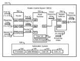
- FIG. 5shows the MCS 500 in greater detail.
- the MCS 500may be configured to receive video, channel the video through one or more sources, and send the video to the air-chain system 600 for broadcast.
- the MCS 500includes a router 502 , a stunt switcher 504 , a bypass switcher 506 , and an automation system 508 , each of which may be connected to each other by a connection mechanism (not shown).
- the router 502may be configured to channel video by mapping inputs to outputs, and may include one or more inputs, including for example, a first input 512 , a second input 514 , and a third input 515 , and one or more outputs, including for example, a first output 516 , a second output 518 , and a third output 519 .
- the router 502may also include a communication interface (not shown).
- the inputs 512 , 514 , 515 , the outputs 516 , 518 , 519 and the communication interfacemay each be connected to each other by a connection mechanism (not shown).
- a routermay and often does have more inputs than outputs such that it may connect many sources to relatively fewer destinations.
- the first RAPD 302may be connected to the router 502 via the output 314 and the input 512 .
- the SVS 400may be connected to the router 502 via the output 402 and the input 514 .
- the second RAPD 303may be connected to the router 502 via the output 318 and the input 515 .
- An example of a routeris the Blackmagic Design Videohub provided by Blackmagic Design Pty. Ltd. Of Fremont, Calif.
- the stunt switcher 504may be configured to channel video by mapping inputs to outputs, and may include one or more inputs, including, for example, a first input 520 , a second input 522 , and a third input 523 , and one or more outputs, including, for example, an output 524 .
- the stunt switcher 504may also include a user interface 528 , a data storage 529 , and a communication interface (not shown).
- the inputs 520 , 522 , 523 , the output 524 , the user interface 528 , the data storage 529 , and the communication interfacemay each be connected to each other by a connection mechanism (not shown).
- the router 502may be connected to the stunt switcher 504 via the output 516 and the input 520 , via the output 518 and the input 522 , and via the output 519 and the input 523 .
- a stunt switchermay and often does have more inputs than outputs such that it may connect many sources to relatively fewer destinations.
- An example of a stunt switcheris the Miranda NVISION NVS5100MC provided by NVision, Inc. of Coppell, Tex.
- the stunt switcher 504may further be configured to perform various functions related to DVEs.
- a DVEis an effect module (e.g., in the form of a set of program instructions) that is configured to be executed or “run.” When run, a DVE dynamically manipulates video being channeled through the stunt switcher.
- Running a DVEmay involve using one or more layers known as “keys” to overlay graphics, video, or other media on video. In some instances, running a DVE may involve simply “resetting” the keys, thereby removing any media being overlayed as a result of another DVE being run.
- the stunt switcher 504may be configured to assist a user in designing a DVE, such as via the user interface 528 . Once a DVE is designed, the stunt switcher 504 may store the DVE in the data storage 529 . In one example, the stunt switcher may store DVEs in respective DVE registers within the data storage 529 . The stunt switcher 504 may also store media used in connection with the DVE in the data storage 529 . This allows the stunt switcher 504 to retrieve media as needed. For example, when running a DVE, the stunt switcher 504 may retrieve media from a particular graphic or video register in the data storage 529 as indicated by the DVE. Media may be stored in the data storage 529 in a variety of manners, such as via a file transfer protocol (FTP). As such, by overwriting media stored in the data storage 529 , the result of a DVE that is run may be changed.
- FTPfile transfer protocol
- the stunt switcher 504may then retrieve and run the DVE. In some instances, this may occur in response to a request being received from a user (e.g., via the user interface 528 ) or from the automation system 508 . Accordingly, when a stunt switcher runs a DVE, a VC that is being channeled through the stunt switcher 504 may be dynamically manipulated. This manipulated video may then be sent through the bypass switcher 506 and to the air-chain system 600 for broadcast as described in greater detail below.
- media used in connection with a DVEmay be stored in another location and sent to the stunt switcher 504 as needed.
- a first and second VC used in connection with a multi-video source DVEmay be stored in the data storage 304 of the RAPS 300 .
- the automation system 508may cause the first RAPD 302 to retrieve the first VC and send it to the stunt switcher 504 via the router 502 .
- the automation system 508may cause the second RAPD 303 to retrieve the second VC and send it to the stunt switcher 504 via the router 502 .
- a multi-video-source DVEis configured to combine multiple videos using respective windows, thereby creating a combined video.
- a multi-video-source DVEmay use a media template (e.g., retrieved from the data storage 529 ), to define the size, shape, and position of each window.
- the stunt switcher 504may receive multiple videos via multiple inputs (as indicated by the DVE). Once received, the stunt switcher may channel the VCs to their respective windows, thereby creating the combined video. The stunt switcher 504 may then send the combined video through the bypass switcher 506 to the air-chain system 600 for broadcast.
- the bypass switcher 506may be configured to channel video by mapping inputs to outputs.
- the bypass switcher 506may include at least one input including, for example, a first input 530 and a second input 532 , and at least one output including, for example, an output 534 .
- the bypass switcher 506may also include a communication interface (not shown).
- the inputs 530 , 532 , the output 534 , and the communication interfacemay all be connected to each other by a connection mechanism (not shown).
- the stunt switcher 504may be connected to the bypass switcher 506 via the output 524 and the input 530 .
- a bypass switchermay and often does have multiple inputs and a single output such that it may connect many sources to relatively fewer destinations.
- a VC sent from the RAPD 302 , 303 to the MCS 500may be channeled through the entities in the MCS and sent out the MCS.
- streaming video sent from the SVS 400 to the MCS 500may be channeled through the entities in the MCS and sent out the MCS.
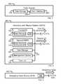
- the automation system 508may be configured to perform or to cause performance of one or more functions related to the television-broadcasting system 100 .
- the automation system 508may include a processor 538 , a data storage 540 , a user-interface 542 (e.g., including a display device), and a communication interface 544 , all of which may be connected by a connection mechanism (not shown).
- the processor 538may include one or more general-purpose processors (e.g., microprocessors) and/or special-purpose processors (e.g., digital signal processors and/or application specific integrated circuits).
- the data storage 550may include one or more volatile and/or non-volatile storage components and may be integrated in whole or in part with the processor 538 .
- the data storage 450may take the form of a non-transitory computer-readable medium and may include a set of program instructions, that when executed by the automation system 508 (e.g., by the processor 538 ), cause performance of a set of functions.
- the automation system 508may cause the RAPS 300 , the SVS 400 , the MCS 500 , the air-chain system 600 , an entity included therein, and/or another entity to perform one of more of the functions described in this disclosure.
- the automation system 508may cause such functions to be performed by sending instructions and/or other data via a corresponding communication interface and/or connection mechanism to the appropriate device.
- the automation system 508may receive data via the same path.
- the automation system 508sends and receives data according to a video disk control protocol (VDCP).
- VDCPvideo disk control protocol
- the automation system 508may receive from the bypass switcher 506 , an indication of the input-to-output mappings used by the bypass switcher such that the automation system may determine whether the scheduled video was actually sent to the air-chain system for broadcast.
- the automation system 508may use these indications to generate an as-run log, which is a report of what was actually broadcast.
- the automation system 508may perform functions described herein as being performed by the traffic system 200 .
- the traffic system 200may perform functions described herein as being performed by the automation system 508 . This may be the case, for example, where the traffic system 200 and the automation system 508 operate using a “live log” approach, where the traffic system 200 may be configured to query the automation system 508 , manage the log and make scheduling-related decisions itself, and provide log entries (perhaps one at a time) to the automation system for processing.
- FIG. 6shows the air-chain system 600 in greater detail.
- the air-chain system 600may be configured to prepare and broadcast video received from the MCS 500 to an audience.
- the air-chain system 600may include an encoder 602 and an outbound-broadcast device (OBD) 604 .
- OBDoutbound-broadcast device
- the encoder 602may be configured to receive video from a source entity, generate a transport stream (TS) (that includes the video), and send the generated TS to a destination entity.
- the TSmay be described as including video, meaning that the TS includes the encoded representation of the video, among other things.
- the encoder 602may include an input 606 and an output 608 , each of which may be connected by a connection mechanism (not shown).
- the bypass switcher 506may be connected to the encoder 602 via the output 534 and the input 606 .
- the encoder 602may generate a TS by, among other things, encoding video based on the HD-SDI standard to video based on the MPEG 2 standard.
- An example of an encoderis the NetVX provided by Harris Corporation of Melbourne, Fla.
- the OBD 604may be configured to receive a TS from a source entity, and broadcast the TS (i.e., including video) to multiple destination entities for viewing by an audience.
- the OBD 604may include an input 610 , and the encoder 602 may be connected to the OBD via the output 608 and the input 610 .
- the term television-broadcast as used in this disclosurerefers broadly to the distribution of video to an audience, and is not meant to be limited to distribution of video in any particular manner.
- the OBD 604may take the form of a transmitter, satellite, or terrestrial fiber transmitter (e.g., any of which may correspond with a service provider).
- the OBD 604may also take the form of a network connection (e.g., for broadcasting the TS to an audience via the Internet).
- the television-broadcasting system 100 described aboveis one non-limiting example. Indeed, the disclosed systems may include some or all of the entities discussed above, and may be arranged in different ways as would be apparent to one of ordinary skill in the art.
- FIGS. 7A and 7Bshow a flow chart illustrating functions in accordance with an example method.
- the methodmay involve the automation system 508 selecting (i.e., retrieving or accessing) a first log-entry from a log.
- the first log-entrymay correspond to a first VC stored in the data storage 304 .
- the first log-entryincludes a house identifier (e.g., stored in a house-identifier field of the log entry) that maps to the first VC.
- the first log-entrymay also correspond to a first start-time (e.g., as represented by an absolute, calculated or manual start time stored in a start-time field of the first log-entry).
- the automation system 508may select the first log-entry according to the corresponding first start-time. For example, if the first log-entry includes a first start-time represented as an absolute start time, the automation system 508 may select the first log-entry at the absolute start time (e.g., when a current time matches the absolute start time). As another example, if the first log-entry includes a first start-time represented as a calculated start time, the automation system 508 may select the first log-entry when the preceding log entry gets “completed” (i.e., when the VC of the previous log entry has played for its corresponding duration).
- the automation system 508may select the first log-entry in response to receiving a request (e.g., from a user) to select the first log-entry.
- a requeste.g., from a user
- the automation system 508may select the first log-entry “ahead of schedule” (e.g., three hours before the first start-time). This may allow the automation system 508 and/or another entity to perform or prepare to perform certain functions in advance of the first start-time.
- the first log-entrymay also include a duration (e.g., in a duration field).
- the durationindicates the duration of the first VC, and therefore the duration is a non-zero duration. This results in the automation system 508 “pausing” on the first log-entry for the duration of the first VC (e.g., for the duration of the first VC as recorded in a RAPD).
- the methodmay involve the automation system 508 selecting a second log-entry.
- the second log-entrymay correspond to a second VC (e.g., stored in the data storage 304 ) and to a multi-video-source DVE (e.g., stored in the data storage 529 ).
- a second VCe.g., stored in the data storage 304
- a multi-video-source DVEe.g., stored in the data storage 529 .
- An example manner in which the second log-entry may correspond to both the second VC and the multi-video-source DVEis described in greater detail below.
- the second log-entrymay correspond to a second start-time, where the second start-time is later than the first start-time (since the first log-entry has a non-zero duration).
- the second log-entrymay also include a duration. However, unlike the first log-entry, the second log-entry may include a zero duration.
- the automation system 508does not “pause” on the second log-entry when traversing the log.
- a traffic systemmay be configured to prevent use of a log entry having a zero duration. In such instances, it may be desired to configure the second log-entry with a nominal duration (e.g., one second) such that the traffic system deems the first log-entry acceptable.
- the methodmay involve the automation system 508 causing the first VC to start being channeled through the stunt switcher 504 proximate (i.e., at or near) the first start-time.
- thismay involve the automation system 508 sending a request to the RAPS 300 to send the first VC to the stunt switcher (according to a protocol understood by the RAPS 300 ), which in turn causes the first RAPD 302 to retrieve and send the second VC to the stunt switcher 504 via the router 502 .
- Thismay allow first VC to be sent to the air-chain system 600 for broadcast.
- the automation system 508may begin performing the related functions in advance of the first start-time such that the first VC is channeled through the stunt switcher 504 proximate the first start-time.
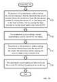
- the methodmay involve the automation system 508 making a first determination that a threshold time-period remains before the second start-time.
- the methodmay involve responsive to the automation system 508 making the first determination that the threshold time-period remains before the second start-time, the automation system causing the second VC to start being sent to the stunt switcher 504 , and further causing the stunt switcher to run the stored multi-video-source DVE.
- the automation system 508 causing the second VC to be sent to the stunt switcher 504may involve the automation system sending a request to the RAPS 300 to send the second VC to the stunt switcher (according to a protocol understood by the RAPS 300 ), which in turn causes the second RAPD 303 to retrieve and send the second VC to the stunt switcher 504 via the router 502 .
- the automation system 508 causing the stunt switcher 504 to run the multi-video-source DVEmay involve the automation system sending a request to the stunt switcher 504 to run the multi-video-source DVE (according to a protocol understood by the stunt switcher).
- a parametermay be included in the log entry (e.g., in the one or more auxiliary-notation fields) that may be used to identify and/or configure the multi-video-source DVE.
- the stunt switcher 504may output a combined video that includes both the first VC and the second VC (e.g., in side-by-side windows as described above). Further in response to the automation system 508 making the first determination, the automation system 508 may select the second VC as the audio source and/or the closed-captioning source for the combined video. However, in some instance one or more of the described effects may be broken up into separate DVEs with each DVE being run separately.
- the threshold time-periodallows the automation system 508 to perform one or more of the described functions according to a “negative offset” of the second start-time.
- the threshold time-periodmay therefore dictate when the stunt switcher 504 runs the multi-video-source DVE, and may be set (e.g., by a user) as desired. For example, if the threshold time-period is forty-five seconds, the stunt switcher 504 may run the multi-video-source DVE forty-five seconds before the second start-time (and therefore forty-five seconds before the first VC ends). For example, at that time the stunt switcher 504 may pull back the first VC into a left window, and add the second VC into a right window.
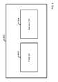
- the stunt switcher 504may output a combined video that includes both the first VC and the second VC as shown in the respective windows.
- FIG. 8shows an example of such a combined video 800 that includes a left window 802 showing the first VC and a right window 804 showing the second VC.
- the multi-video-source DVEmay cause the second VC to be selected as the audio source and/or the closed-captioning source for the combined video.
- the stunt switcher 504may then output the combined video, such that it may be sent to an air-chain system 600 for broadcast.
- the methodmay involve the automation system 508 making a second determination that the second VC has ended (i.e., when the second VC has been played for its duration).
- the methodmay involve responsive to the automation system 508 making the second determination that the second VC has ended, the automation system causing the stunt switcher 504 to run a restore DVE (e.g., stored in the data storage 529 ). Therefore, once the second VC ends (e.g., after thirty seconds assuming that the second VC has a duration of thirty seconds), the automation system 508 may resume channeling the first VC through the stunt switcher 504 .
- a restore DVEe.g., stored in the data storage 529
- a restore DVEmay be configured to (when run) effectively terminate the multi-video-source DVE (i.e., by removing the windows and causing only the first VC to be channeled through the stunt switcher.
- the restore DVEmay also select the first VC as the audio source and/or the closed captioning source for the output of the stunt switcher 504 .
- the automation system 508may continue broadcasting video as scheduled in the log.
- DVEsWhile certain types of DVEs has been described above (e.g., a multi-video source DVE and a restore DVE), in some instances additional DVEs may be run to provide smooth video transitions before or after running another DVE.
- a transition DVEmay be run just before the multi-video-source DVE is run, and may provide a transition such as by slowly pulling back the full-frame first VC into the left window of the combined video that is provided by the multi-video-source DVE.
- a transition DVEmay be run between the running of the multi-video-source DVE and the restore DVE such as to slowly push the second VC in the right window to full-frame.
- the methodmay involve the automation system 508 adding an indication that the first and/or second VC has been broadcast to an as-run log. In one example, the automation system 508 may further indicate how long the first and/or second VC was broadcast.
- the second log-entrymay include an identifier that maps to a set of scripts (or other program instructions), such as PHP-Hypertext-Preprocessor (PHP) scripts, that when executed by the automation system 508 cause the automation system to perform one or more of the functions, such as those at blocks 708 - 714 as described above.
- PGPPHP-Hypertext-Preprocessor
- other types of scriptsmay also be used, including for example customized scripts that are configured to perform functions in a television-broadcasting environment. Such scripts may be executed by a corresponding interpreter installed in the automation system 508 .
- the identifiermay be stored in a house-identifier field of the second log-entry.
- the identifiermay have a particular property (e.g., a predefined prefix) to allow the automation system 508 to differentiate between the identifier and a house identifier that is typically included in a house-identifier field (e.g., as with the second log-entry described above).
- a particular propertye.g., a predefined prefix
- the automation system 508may execute the set of scripts and therefore, perform the corresponding functions.
- the automation system 508may begin executing the set of scripts proximate the second start-time or perhaps in advance of the second start-time (e.g., based on a negative offset) as described above.
- the “START_TIME_OFFSET ( ⁇ offset>)” commandmay cause the automation system 508 to wait until a target time to proceed.
- the target timeis defined by a negative offset of the second start-time.
- START_TIME_OFFSET ( ⁇ 900)would halt the automation system's execution of the scripts at this command until 900 frames before the second start-time.
- the automation system 508 making a first determination that a threshold time-period remains before the second start-timemay involve the automation system determining that a current time equals the defined negative offset of the second start-time.
- a variety of other timing techniquesmay be used.
- the “LOAD_AND_ROUTE ( ⁇ second-VC house-identifier>, ⁇ second-VC token>, ⁇ stunt-switcher identifier>)” commandmay cause the automation system 508 to cause a second VC to be loaded and routed (sent) to an input of the stunt switcher 504 .
- the second-VC house-identifiermaps to the second VC.
- the second-VC tokenmay be used as an identifier such that other scripts (such as the “RUN_EFFECT_PLAY_RUN_EFFECT” command described below) may refer to the second VC without identifying a particular physical input of the stunt switcher 504 .
- the stunt switcher 504may route video without indicating to other devices the particular physical input it is using.
- the stunt-switcher identifieridentifies a particular stunt switcher that will be used. For example, a “LOAD_AND_ROUTE (PR1234, T, 504 )” command may cause the automation system 508 to load the second VC mapped to by PR1234 in the RAPD 303 such that it may send the second VC (via the router 502 ) to an input of the stunt switcher 504 . The automation system 508 may then use the token T to refer to the loaded second VC that will be sent in this manner.
- the “RUN_EFFECT_PLAY_RUN_EFFECT ( ⁇ multi-video-source DVE identifier>, ⁇ restore-DVE identifier>, ⁇ stunt-switcher identifier>, ⁇ second-VC token>) commandmay cause the automation system 508 to cause a stunt switcher to run a multi-video-source DVE that uses the second VC (together with the first VC). Further, once the second VC ends, the automation system 508 may cause the stunt switcher to run a restore DVE.
- the multi-video-source DVE identifieridentifies the multi-source DVE to run, and the second-VC token identifies the loaded second VC to use in connection with the multi-video-source DVE.
- the restore-DVE identifieridentifies the restore DVE to run once the second VC ends.
- the stunt-switcher identifieridentifies the stunt switcher that should run the multi-video-source and the restore DVEs, and that should receive the second VC.
- the command “RUN_EFFECT_PLAY_RUN_EFFECT ( 20 , 21 , 504 , T)may cause the automation system 508 to cause the stunt switcher 504 to run a multi-video-source DVE identified as DVE 20 (stored in the data storage 529 ). Further, the command may cause the automation system 508 to use in connection with the multi-video-source DVE, the second VC routed in accordance with the “LOAD_AND_ROUTE” command described above, and referred to by the second-VC token T. Then, once the second VC ends, the automation system 508 may cause the stunt switcher 504 to run the restore DVE identified as DVE 21 .
- the “EXIT” commandmay terminate the automation system's 508 execution of the set of scripts.
- the set of scriptsmay also be used to perform other functions, including for example adding an indication that the first and/or second VC has been broadcast to an as-run log as described above. Further, the scripts may provide a “time out” period and a corresponding action to handle an instance in which the set of scripts runs for longer than the time out period. For example, the action may involve simply terminating execution of the set of scripts.
- a usermay include an appropriate identifier in a traffic entry of the log to easily cause a stunt switcher to run a multi-video-source DVE and/or a restore DVE at an appropriate time as configured in the corresponding set of scripts.
- the second log-entrymay be positioned as the next log entry after the first log entry.
- the automation system 508select log entries ahead of schedule. For example, the automation system 508 may select the second log-entry before the second start-time, such that it may perform appropriate actions that are timed according to the negative offset as described above. This may result in the automation system 508 performing functions related to both the first and second log entries simultaneously, or perhaps contemporaneously. For example, the automation system 508 may cause a VC to be channeled through the stunt switcher 504 , while simultaneously executing a set of scripts. As the set of scripts execute, the corresponding functions may be performed, and therefore both the first VC and the second VC broadcast at the same time (as the multi-video-source DVE is run).
- the functionsmay be performed by any entity, such as those included in the television-broadcasting system 100 described above.
- the described steps throughout this applicationneed not be performed in the disclosed order, although in some examples, an order may be preferred. Also, not all steps need to be performed to achieve the desired advantages of the disclosed systems and methods, and therefore not all steps are required. Further, the variations described throughout this disclose may be applicable to any of the disclosed systems or methods.
Landscapes
- Engineering & Computer Science (AREA)
- Multimedia (AREA)
- Signal Processing (AREA)
- Business, Economics & Management (AREA)
- Marketing (AREA)
- Computer Networks & Wireless Communication (AREA)
- Databases & Information Systems (AREA)
- Two-Way Televisions, Distribution Of Moving Picture Or The Like (AREA)
Abstract
Description
- “a” or “an” is meant to read as “at least one.”
- “the” is meant to be read as “the at least one.”
- the term “video” refers to any material represented in a video format (i.e., having multiple frames). In some instances, video may include multiple sequential frames that are identical or nearly identical, and that may give the impression of a still image. Video may or may not include an audio portion.
- the term “video component” (VC) refers to video that one of ordinary skill in the art would typically consider to be self-contained, and that is typically separately scheduled by a traffic system (also referred to as a scheduling-and-sequencing system) of a television-broadcasting system.
- START_TIME_OFFSET (<offset>)
- LOAD_AND_ROUTE (<second-VC house-identifier>, <second-VC token>, <stunt-switcher identifier>)
- RUN_EFFECT_PLAY_RUN_EFFECT (<multi-video-source DVE identifier>, <restore-DVE identifier>, <stunt-switcher identifier>, <second-VC token>)
- EXIT.
Claims (26)
Priority Applications (2)
| Application Number | Priority Date | Filing Date | Title |
|---|---|---|---|
| US13/829,017US9549208B1 (en) | 2013-03-14 | 2013-03-14 | Systems and methods for causing a stunt switcher to run a multi-video-source DVE |
| US15/370,177US9883220B1 (en) | 2013-03-14 | 2016-12-06 | Systems and methods for causing a stunt switcher to run a multi-video-source DVE |
Applications Claiming Priority (1)
| Application Number | Priority Date | Filing Date | Title |
|---|---|---|---|
| US13/829,017US9549208B1 (en) | 2013-03-14 | 2013-03-14 | Systems and methods for causing a stunt switcher to run a multi-video-source DVE |
Related Child Applications (1)
| Application Number | Title | Priority Date | Filing Date |
|---|---|---|---|
| US15/370,177ContinuationUS9883220B1 (en) | 2013-03-14 | 2016-12-06 | Systems and methods for causing a stunt switcher to run a multi-video-source DVE |
Publications (1)
| Publication Number | Publication Date |
|---|---|
| US9549208B1true US9549208B1 (en) | 2017-01-17 |
Family
ID=57749482
Family Applications (2)
| Application Number | Title | Priority Date | Filing Date |
|---|---|---|---|
| US13/829,017Expired - Fee RelatedUS9549208B1 (en) | 2013-03-14 | 2013-03-14 | Systems and methods for causing a stunt switcher to run a multi-video-source DVE |
| US15/370,177Expired - Fee RelatedUS9883220B1 (en) | 2013-03-14 | 2016-12-06 | Systems and methods for causing a stunt switcher to run a multi-video-source DVE |
Family Applications After (1)
| Application Number | Title | Priority Date | Filing Date |
|---|---|---|---|
| US15/370,177Expired - Fee RelatedUS9883220B1 (en) | 2013-03-14 | 2016-12-06 | Systems and methods for causing a stunt switcher to run a multi-video-source DVE |
Country Status (1)
| Country | Link |
|---|---|
| US (2) | US9549208B1 (en) |
Cited By (3)
| Publication number | Priority date | Publication date | Assignee | Title |
|---|---|---|---|---|
| US9883220B1 (en)* | 2013-03-14 | 2018-01-30 | Tribune Broadcasting Company, Llc | Systems and methods for causing a stunt switcher to run a multi-video-source DVE |
| US10021442B1 (en)* | 2013-03-14 | 2018-07-10 | Tribune Broadcasting Company, Llc | Systems and methods for causing a stunt switcher to run a bug-removal DVE |
| US10104449B1 (en) | 2013-03-14 | 2018-10-16 | Tribune Broadcasting Company, Llc | Systems and methods for causing a stunt switcher to run a bug-overlay DVE |
Citations (73)
| Publication number | Priority date | Publication date | Assignee | Title |
|---|---|---|---|---|
| US5485611A (en)* | 1994-12-30 | 1996-01-16 | Intel Corporation | Video database indexing and method of presenting video database index to a user |
| US5852565A (en)* | 1996-01-30 | 1998-12-22 | Demografx | Temporal and resolution layering in advanced television |
| US5892535A (en) | 1996-05-08 | 1999-04-06 | Digital Video Systems, Inc. | Flexible, configurable, hierarchical system for distributing programming |
| US6020931A (en)* | 1996-04-25 | 2000-02-01 | George S. Sheng | Video composition and position system and media signal communication system |
| US6069668A (en)* | 1997-04-07 | 2000-05-30 | Pinnacle Systems, Inc. | System and method for producing video effects on live-action video |
| US6169542B1 (en)* | 1998-12-14 | 2001-01-02 | Gte Main Street Incorporated | Method of delivering advertising through an interactive video distribution system |
| US6198906B1 (en) | 1996-10-07 | 2001-03-06 | Sony Corporation | Method and apparatus for performing broadcast operations |
| US20010003846A1 (en)* | 1999-05-19 | 2001-06-14 | New Horizons Telecasting, Inc. | Encapsulated, streaming media automation and distribution system |
| US6374336B1 (en)* | 1997-12-24 | 2002-04-16 | Avid Technology, Inc. | Computer system and process for transferring multiple high bandwidth streams of data between multiple storage units and multiple applications in a scalable and reliable manner |
| US20020107940A1 (en) | 2000-12-12 | 2002-08-08 | Brassil John T. | Media program timing and identity delivery method and system |
| US20020184047A1 (en) | 2001-04-03 | 2002-12-05 | Plotnick Michael A. | Universal ad queue |
| US20030005437A1 (en)* | 2001-06-01 | 2003-01-02 | Norman Feuer | Networked broadcasting system with demographically controlled advertisement selection |
| US20030001880A1 (en) | 2001-04-18 | 2003-01-02 | Parkervision, Inc. | Method, system, and computer program product for producing and distributing enhanced media |
| US20030097664A1 (en)* | 2001-11-21 | 2003-05-22 | James Meyers | Method and system for interactive movie scene television |
| US20030126597A1 (en) | 2000-02-01 | 2003-07-03 | Geoffrey Darby | On-screen stripe and other methods for delivering information that facilitate convergence of audio/visual programming and advertisements with internet and other media usage |
| US20030146915A1 (en) | 2001-10-12 | 2003-08-07 | Brook John Charles | Interactive animation of sprites in a video production |
| US20030184679A1 (en)* | 2002-03-29 | 2003-10-02 | Meehan Joseph Patrick | Method, apparatus, and program for providing slow motion advertisements in video information |
| US20030188321A1 (en)* | 1996-06-05 | 2003-10-02 | Microsoft Corporation | System and method for linking video, services and applications in an interactive television system |
| US20040038691A1 (en)* | 1999-07-31 | 2004-02-26 | Lg Information & Communications, Ltd. | Method for performing cell broadcasting and communication system using the same |
| US20040107136A1 (en)* | 2002-07-12 | 2004-06-03 | Nemirofsky Frank Robert | Interactive electronic commerce system facilitating management of advertising, promotion and information interchange messages |
| US20040210945A1 (en) | 2000-08-08 | 2004-10-21 | Parkervision, Inc. | Building macro elements for production automation control |
| US20050062888A1 (en)* | 2003-09-19 | 2005-03-24 | Wood Anthony John | Apparatus and method for presentation of portably-stored content on an high-definition display |
| US20050120279A1 (en)* | 2003-11-19 | 2005-06-02 | Hitachi, Ltd. | Storage subsystem, storage system, and communication control method |
| US20050229227A1 (en) | 2004-04-13 | 2005-10-13 | Evenhere, Inc. | Aggregation of retailers for televised media programming product placement |
| US20050273835A1 (en)* | 2004-05-14 | 2005-12-08 | Ryan Steelberg | System and method for utilizing dual feedback loops |
| US7010530B2 (en) | 2000-01-06 | 2006-03-07 | George P. Johnson Company | Event management system |
| US7051354B2 (en) | 2003-01-24 | 2006-05-23 | Thomson Licensing | System and method for advertising a currently airing program through the use of an electronic program guide interface |
| US20060143650A1 (en) | 2003-07-03 | 2006-06-29 | Kentaro Tanikawa | Video processing apparatus, ic circuit for video processing apparatus, video processing method, and video processing program |
| US20060174281A1 (en)* | 2005-02-03 | 2006-08-03 | Lg Electronics Inc. | Video apparatus and method for controlling the same |
| US20070022437A1 (en)* | 2005-07-19 | 2007-01-25 | David Gerken | Methods and apparatus for providing content and services coordinated with television content |
| US20070067800A1 (en) | 1998-06-29 | 2007-03-22 | Nds Limited | Advanced television system |
| US20070113264A1 (en)* | 2001-11-20 | 2007-05-17 | Rothschild Trust Holdings, Llc | System and method for updating digital media content |
| US20070143786A1 (en) | 2005-12-16 | 2007-06-21 | General Electric Company | Embedded advertisements and method of advertising |
| US20070162951A1 (en) | 2000-04-28 | 2007-07-12 | Rashkovskiy Oleg B | Providing content interruptions |
| US20070192788A1 (en) | 2003-09-12 | 2007-08-16 | Christof Danzl | Method to provide logging information of an application in a digital broadcast system |
| US20070220544A1 (en)* | 2005-09-20 | 2007-09-20 | Jon Nash-Putnam | Method, system and program product for broadcast advertising and other broadcast content performance verification utilizing digital artifacts |
| US20070261090A1 (en)* | 2006-03-24 | 2007-11-08 | Miller Eric B | Interactive television application distribution, control, and communication system and methods |
| US20080010342A1 (en) | 1999-06-15 | 2008-01-10 | Wink Communications, Inc. | Synchronous updating of dynamic interactive applications |
| US20080244663A1 (en)* | 2007-03-26 | 2008-10-02 | The Directv Group, Inc. | Method and system for inserting digital video effects into a video stream using a bypass router |
| US20080239162A1 (en)* | 2007-03-26 | 2008-10-02 | The Directv Group, Inc. | Method and system for inserting digital video effects into a video stream at a multiplexing device after routing |
| US20080250448A1 (en) | 2007-04-03 | 2008-10-09 | Google Inc. | Log Processing |
| US20080276269A1 (en) | 2007-05-02 | 2008-11-06 | Christoform Miller | User Interfaces For Web-Based Video Player |
| US20090070807A1 (en) | 2007-09-10 | 2009-03-12 | The Directv Group, Inc. | Method and System for Placing Inserts into a Broadcast Television Signal |
| US20090070837A1 (en) | 2007-09-10 | 2009-03-12 | The Directv Group, Inc. | Method and System for Forming a Countdown Clock Channel Output |
| US20090070808A1 (en)* | 2007-09-10 | 2009-03-12 | The Directv Group, Inc. | Method and system for tracking actual channel content output |
| US20090268806A1 (en)* | 2008-04-07 | 2009-10-29 | Jin Pil Kim | Method of transmitting and receiving broadcasting signal and apparatus for receiving broadcasting signal |
| US20090276805A1 (en) | 2008-05-03 | 2009-11-05 | Andrews Ii James K | Method and system for generation and playback of supplemented videos |
| US20100050083A1 (en) | 2006-07-06 | 2010-02-25 | Sundaysky Ltd. | Automatic generation of video from structured content |
| US20100166257A1 (en) | 2008-12-30 | 2010-07-01 | Ati Technologies Ulc | Method and apparatus for detecting semi-transparencies in video |
| US7903903B1 (en) | 2004-02-20 | 2011-03-08 | Broadcast Pix, Inc. | Integrated live video production system |
| US20110283311A1 (en) | 2010-05-14 | 2011-11-17 | Rovi Technologies Corporation | Systems and methods for media detection and filtering using a parental control logging application |
| US20110293244A1 (en)* | 2010-05-25 | 2011-12-01 | Nikon Corporation | Imaging device |
| US20110321084A1 (en) | 2010-06-25 | 2011-12-29 | Kddi Corporation | Apparatus and method for optimizing on-screen location of additional content overlay on video content |
| US20120084811A1 (en) | 2010-10-04 | 2012-04-05 | Mark Thompson | System and Method for Integrating E-Commerce Into Real Time Video Content Advertising |
| US8201201B2 (en) | 2005-02-25 | 2012-06-12 | Lightningcast Llc | Inserting branding elements |
| US20120185905A1 (en) | 2011-01-13 | 2012-07-19 | Christopher Lee Kelley | Content Overlay System |
| US8259232B2 (en) | 2008-09-22 | 2012-09-04 | Sony Corporation | Image display apparatus and image display method |
| US20120291067A1 (en) | 2011-05-11 | 2012-11-15 | Wiles Brian C | Integrated digital broadcasting system, network, and methods |
| US20130055306A1 (en) | 2002-02-27 | 2013-02-28 | United Video Properties, Inc. | Video clipping system and method |
| US20130272678A1 (en) | 2006-12-12 | 2013-10-17 | Time Warner, Inc. | Method and apparatus for concealing portions of a video screen |
| US20140089966A1 (en) | 2008-01-30 | 2014-03-27 | Cinsay, Inc. | Interactive product placement system and method therefor |
| US8752087B2 (en)* | 2008-11-07 | 2014-06-10 | At&T Intellectual Property I, L.P. | System and method for dynamically constructing personalized contextual video programs |
| US20140165097A1 (en) | 2012-12-11 | 2014-06-12 | Cbs Interactive Inc. | Techniques to broadcast a network television program |
| US20140195675A1 (en) | 2013-01-09 | 2014-07-10 | Giga Entertainment Media Inc. | Simultaneous Content Data Streaming And Interaction System |
| US8789124B1 (en) | 2010-05-28 | 2014-07-22 | Music Choice | Cross platform application control in an interactive, multi-platform video network |
| US20140259051A1 (en) | 2013-03-05 | 2014-09-11 | Disney Enterprises, Inc. | Automatic creation of frame accurate program/commercial triggers for live/automated television programs |
| US20140259074A1 (en) | 2006-12-29 | 2014-09-11 | Prodea Systems, Inc. | Display inserts, overlays, and graphical user interfaces for multimedia systems |
| US20140304366A1 (en) | 2013-04-06 | 2014-10-09 | Miranda Technologies Partnership | Systems and methods for a media playout card |
| US20140317666A1 (en) | 2013-04-18 | 2014-10-23 | Disney Enterprises, Inc. | Recipient Specific Lists for Distribution of Media Content |
| US20140358267A1 (en)* | 2006-09-26 | 2014-12-04 | Clear Channel Management Services, Inc. | Scheduling Advertising During Restricted Periods |
| US20140373044A1 (en) | 2012-02-27 | 2014-12-18 | Linear Acoustic, Inc. | Automatic parametric control of audio processing via automation events |
| US20140380394A1 (en) | 2013-06-21 | 2014-12-25 | France Brevets | Device and method for composing programmes from different sources in baseband |
| US9396475B2 (en)* | 2007-02-01 | 2016-07-19 | Invidi Technologies Corporation | Intelligent targeting of tags in a broadcast network |
Family Cites Families (8)
| Publication number | Priority date | Publication date | Assignee | Title |
|---|---|---|---|---|
| NZ259147A (en)* | 1992-12-09 | 1997-05-26 | Discovery Communicat Inc | Network controller for cable television |
| JPH0879391A (en) | 1994-09-02 | 1996-03-22 | Fujitsu Ltd | Electronic conference system |
| US7337231B1 (en)* | 2000-12-18 | 2008-02-26 | Nortel Networks Limited | Providing media on demand |
| CN100423589C (en)* | 2003-11-12 | 2008-10-01 | Ut斯达康(中国)有限公司 | Packet data united dispatch performing method and apparatus in down-link multiple-channel of mobile communication system |
| US8089959B2 (en)* | 2006-05-30 | 2012-01-03 | Ted Henryk Szymanski | Method and apparatus to schedule packets through a crossbar switch with delay guarantees |
| US9535988B2 (en)* | 2007-12-21 | 2017-01-03 | Yahoo! Inc. | Blog-based video summarization |
| US8726310B2 (en)* | 2009-02-05 | 2014-05-13 | Purplecomm Inc. | Meta channel media system control and advertisement technology |
| US9549208B1 (en)* | 2013-03-14 | 2017-01-17 | Tribune Broadcasting Company, Llc | Systems and methods for causing a stunt switcher to run a multi-video-source DVE |
- 2013
- 2013-03-14USUS13/829,017patent/US9549208B1/ennot_activeExpired - Fee Related
- 2016
- 2016-12-06USUS15/370,177patent/US9883220B1/ennot_activeExpired - Fee Related
Patent Citations (76)
| Publication number | Priority date | Publication date | Assignee | Title |
|---|---|---|---|---|
| US5485611A (en)* | 1994-12-30 | 1996-01-16 | Intel Corporation | Video database indexing and method of presenting video database index to a user |
| US5852565A (en)* | 1996-01-30 | 1998-12-22 | Demografx | Temporal and resolution layering in advanced television |
| US6020931A (en)* | 1996-04-25 | 2000-02-01 | George S. Sheng | Video composition and position system and media signal communication system |
| US5892535A (en) | 1996-05-08 | 1999-04-06 | Digital Video Systems, Inc. | Flexible, configurable, hierarchical system for distributing programming |
| US20030188321A1 (en)* | 1996-06-05 | 2003-10-02 | Microsoft Corporation | System and method for linking video, services and applications in an interactive television system |
| US6198906B1 (en) | 1996-10-07 | 2001-03-06 | Sony Corporation | Method and apparatus for performing broadcast operations |
| US6069668A (en)* | 1997-04-07 | 2000-05-30 | Pinnacle Systems, Inc. | System and method for producing video effects on live-action video |
| US6374336B1 (en)* | 1997-12-24 | 2002-04-16 | Avid Technology, Inc. | Computer system and process for transferring multiple high bandwidth streams of data between multiple storage units and multiple applications in a scalable and reliable manner |
| US20070067800A1 (en) | 1998-06-29 | 2007-03-22 | Nds Limited | Advanced television system |
| US6169542B1 (en)* | 1998-12-14 | 2001-01-02 | Gte Main Street Incorporated | Method of delivering advertising through an interactive video distribution system |
| US20010003846A1 (en)* | 1999-05-19 | 2001-06-14 | New Horizons Telecasting, Inc. | Encapsulated, streaming media automation and distribution system |
| US20080010342A1 (en) | 1999-06-15 | 2008-01-10 | Wink Communications, Inc. | Synchronous updating of dynamic interactive applications |
| US20040038691A1 (en)* | 1999-07-31 | 2004-02-26 | Lg Information & Communications, Ltd. | Method for performing cell broadcasting and communication system using the same |
| US7010530B2 (en) | 2000-01-06 | 2006-03-07 | George P. Johnson Company | Event management system |
| US20030126597A1 (en) | 2000-02-01 | 2003-07-03 | Geoffrey Darby | On-screen stripe and other methods for delivering information that facilitate convergence of audio/visual programming and advertisements with internet and other media usage |
| US20070162951A1 (en) | 2000-04-28 | 2007-07-12 | Rashkovskiy Oleg B | Providing content interruptions |
| US20040210945A1 (en) | 2000-08-08 | 2004-10-21 | Parkervision, Inc. | Building macro elements for production automation control |
| US20020107940A1 (en) | 2000-12-12 | 2002-08-08 | Brassil John T. | Media program timing and identity delivery method and system |
| US20020184047A1 (en) | 2001-04-03 | 2002-12-05 | Plotnick Michael A. | Universal ad queue |
| US20030001880A1 (en) | 2001-04-18 | 2003-01-02 | Parkervision, Inc. | Method, system, and computer program product for producing and distributing enhanced media |
| US20030005437A1 (en)* | 2001-06-01 | 2003-01-02 | Norman Feuer | Networked broadcasting system with demographically controlled advertisement selection |
| US20030146915A1 (en) | 2001-10-12 | 2003-08-07 | Brook John Charles | Interactive animation of sprites in a video production |
| US20070113264A1 (en)* | 2001-11-20 | 2007-05-17 | Rothschild Trust Holdings, Llc | System and method for updating digital media content |
| US20030097664A1 (en)* | 2001-11-21 | 2003-05-22 | James Meyers | Method and system for interactive movie scene television |
| US20130055306A1 (en) | 2002-02-27 | 2013-02-28 | United Video Properties, Inc. | Video clipping system and method |
| US20030184679A1 (en)* | 2002-03-29 | 2003-10-02 | Meehan Joseph Patrick | Method, apparatus, and program for providing slow motion advertisements in video information |
| US20040107136A1 (en)* | 2002-07-12 | 2004-06-03 | Nemirofsky Frank Robert | Interactive electronic commerce system facilitating management of advertising, promotion and information interchange messages |
| US7051354B2 (en) | 2003-01-24 | 2006-05-23 | Thomson Licensing | System and method for advertising a currently airing program through the use of an electronic program guide interface |
| US20060143650A1 (en) | 2003-07-03 | 2006-06-29 | Kentaro Tanikawa | Video processing apparatus, ic circuit for video processing apparatus, video processing method, and video processing program |
| US20070192788A1 (en) | 2003-09-12 | 2007-08-16 | Christof Danzl | Method to provide logging information of an application in a digital broadcast system |
| US20050062888A1 (en)* | 2003-09-19 | 2005-03-24 | Wood Anthony John | Apparatus and method for presentation of portably-stored content on an high-definition display |
| US20050120279A1 (en)* | 2003-11-19 | 2005-06-02 | Hitachi, Ltd. | Storage subsystem, storage system, and communication control method |
| US7903903B1 (en) | 2004-02-20 | 2011-03-08 | Broadcast Pix, Inc. | Integrated live video production system |
| US20050229227A1 (en) | 2004-04-13 | 2005-10-13 | Evenhere, Inc. | Aggregation of retailers for televised media programming product placement |
| US20050273835A1 (en)* | 2004-05-14 | 2005-12-08 | Ryan Steelberg | System and method for utilizing dual feedback loops |
| US20060174281A1 (en)* | 2005-02-03 | 2006-08-03 | Lg Electronics Inc. | Video apparatus and method for controlling the same |
| US8201201B2 (en) | 2005-02-25 | 2012-06-12 | Lightningcast Llc | Inserting branding elements |
| US20070022437A1 (en)* | 2005-07-19 | 2007-01-25 | David Gerken | Methods and apparatus for providing content and services coordinated with television content |
| US20070220544A1 (en)* | 2005-09-20 | 2007-09-20 | Jon Nash-Putnam | Method, system and program product for broadcast advertising and other broadcast content performance verification utilizing digital artifacts |
| US20070143786A1 (en) | 2005-12-16 | 2007-06-21 | General Electric Company | Embedded advertisements and method of advertising |
| US20070261090A1 (en)* | 2006-03-24 | 2007-11-08 | Miller Eric B | Interactive television application distribution, control, and communication system and methods |
| US20100050083A1 (en) | 2006-07-06 | 2010-02-25 | Sundaysky Ltd. | Automatic generation of video from structured content |
| US20140358267A1 (en)* | 2006-09-26 | 2014-12-04 | Clear Channel Management Services, Inc. | Scheduling Advertising During Restricted Periods |
| US20130272678A1 (en) | 2006-12-12 | 2013-10-17 | Time Warner, Inc. | Method and apparatus for concealing portions of a video screen |
| US20140259074A1 (en) | 2006-12-29 | 2014-09-11 | Prodea Systems, Inc. | Display inserts, overlays, and graphical user interfaces for multimedia systems |
| US9396475B2 (en)* | 2007-02-01 | 2016-07-19 | Invidi Technologies Corporation | Intelligent targeting of tags in a broadcast network |
| US20080244663A1 (en)* | 2007-03-26 | 2008-10-02 | The Directv Group, Inc. | Method and system for inserting digital video effects into a video stream using a bypass router |
| US20080239162A1 (en)* | 2007-03-26 | 2008-10-02 | The Directv Group, Inc. | Method and system for inserting digital video effects into a video stream at a multiplexing device after routing |
| US20080250447A1 (en) | 2007-04-03 | 2008-10-09 | Google Inc. | Log Processing |
| US20080250448A1 (en) | 2007-04-03 | 2008-10-09 | Google Inc. | Log Processing |
| US20080276269A1 (en) | 2007-05-02 | 2008-11-06 | Christoform Miller | User Interfaces For Web-Based Video Player |
| US20090070807A1 (en) | 2007-09-10 | 2009-03-12 | The Directv Group, Inc. | Method and System for Placing Inserts into a Broadcast Television Signal |
| US20090070837A1 (en) | 2007-09-10 | 2009-03-12 | The Directv Group, Inc. | Method and System for Forming a Countdown Clock Channel Output |
| US20090070808A1 (en)* | 2007-09-10 | 2009-03-12 | The Directv Group, Inc. | Method and system for tracking actual channel content output |
| US20140089966A1 (en) | 2008-01-30 | 2014-03-27 | Cinsay, Inc. | Interactive product placement system and method therefor |
| US20090268806A1 (en)* | 2008-04-07 | 2009-10-29 | Jin Pil Kim | Method of transmitting and receiving broadcasting signal and apparatus for receiving broadcasting signal |
| US20090276805A1 (en) | 2008-05-03 | 2009-11-05 | Andrews Ii James K | Method and system for generation and playback of supplemented videos |
| US8259232B2 (en) | 2008-09-22 | 2012-09-04 | Sony Corporation | Image display apparatus and image display method |
| US8752087B2 (en)* | 2008-11-07 | 2014-06-10 | At&T Intellectual Property I, L.P. | System and method for dynamically constructing personalized contextual video programs |
| US20100166257A1 (en) | 2008-12-30 | 2010-07-01 | Ati Technologies Ulc | Method and apparatus for detecting semi-transparencies in video |
| US20110283311A1 (en) | 2010-05-14 | 2011-11-17 | Rovi Technologies Corporation | Systems and methods for media detection and filtering using a parental control logging application |
| US20110293244A1 (en)* | 2010-05-25 | 2011-12-01 | Nikon Corporation | Imaging device |
| US8789124B1 (en) | 2010-05-28 | 2014-07-22 | Music Choice | Cross platform application control in an interactive, multi-platform video network |
| US20110321084A1 (en) | 2010-06-25 | 2011-12-29 | Kddi Corporation | Apparatus and method for optimizing on-screen location of additional content overlay on video content |
| US20120084811A1 (en) | 2010-10-04 | 2012-04-05 | Mark Thompson | System and Method for Integrating E-Commerce Into Real Time Video Content Advertising |
| US20120185905A1 (en) | 2011-01-13 | 2012-07-19 | Christopher Lee Kelley | Content Overlay System |
| US20120291067A1 (en) | 2011-05-11 | 2012-11-15 | Wiles Brian C | Integrated digital broadcasting system, network, and methods |
| US20140373044A1 (en) | 2012-02-27 | 2014-12-18 | Linear Acoustic, Inc. | Automatic parametric control of audio processing via automation events |
| US20140165097A1 (en) | 2012-12-11 | 2014-06-12 | Cbs Interactive Inc. | Techniques to broadcast a network television program |
| US20140195675A1 (en) | 2013-01-09 | 2014-07-10 | Giga Entertainment Media Inc. | Simultaneous Content Data Streaming And Interaction System |
| US20140259051A1 (en) | 2013-03-05 | 2014-09-11 | Disney Enterprises, Inc. | Automatic creation of frame accurate program/commercial triggers for live/automated television programs |
| US20140304366A1 (en) | 2013-04-06 | 2014-10-09 | Miranda Technologies Partnership | Systems and methods for a media playout card |
| US20140304367A1 (en) | 2013-04-06 | 2014-10-09 | Miranda Technologies Partnership | Systems and methods for media distribution and management |
| US9002991B2 (en) | 2013-04-06 | 2015-04-07 | Miranda Technologies Partnership | System and methods for cloud-based media play out |
| US20140317666A1 (en) | 2013-04-18 | 2014-10-23 | Disney Enterprises, Inc. | Recipient Specific Lists for Distribution of Media Content |
| US20140380394A1 (en) | 2013-06-21 | 2014-12-25 | France Brevets | Device and method for composing programmes from different sources in baseband |
Non-Patent Citations (26)
| Title |
|---|
| Advisory Action dated Sep. 24, 2014 of U.S. Appl. No. 13/828,682, filed Mar. 14, 2013. |
| Final office action dated Jun. 24, 2014 of U.S. Appl. No. 13/828,682, filed Mar. 14, 2013. |
| Hundemer, Hank J. U.S. Appl. No. 13/828,632, filed Mar. 14, 2013, 41 pages. |
| Hundemer, Hank J., U.S Appl. No. 14/724,469, filed May 28, 2015, 41 pages. |
| Hundemer, Hank J., U.S. Appl. No. 13/828,682, filed Mar. 14, 2013, 40 pages. |
| Hundemer, Hank J., U.S. Appl. No. 13/828,939, filed Mar. 14, 2013, 47 pages. |
| Hundemer, Hank J., U.S. Appl. No. 13/829,150, filed Mar. 14, 2013, 41 pages. |
| Hundemer, Hank J., U.S. Appl. No. 13/829,368, filed Mar. 14, 2013, 52 pages. |
| Hundemer, Hank J., U.S. Appl. No. 14/458,789, filed Aug. 13, 2014, 39 pages. |
| Non-Final Office Action dated Jan. 12, 2015 of U.S. Appl. No. 13/829,368, filed Mar. 14, 2013. |
| Non-Final Office Action dated Jan. 29, 2016 of U.S. Appl. No. 14/458,789, filed Aug. 13, 2014. |
| Non-Final Office Action dated Jan. 5, 2015 of U.S. Appl. No. 13/828,632, filed Mar. 14, 2013. |
| Non-final office action dated Jul. 3, 2014 of U.S. Appl. No. 13/829,368, filed Mar. 14, 2013. |
| Non-final office action dated Jun. 26, 2014 of U.S. Appl. No. 13/829,150, filed Mar. 14, 2013. |
| Non-final office action dated Mar. 7, 2014 of U.S. Appl. No. 13/828,682, filed Mar. 14, 2013. |
| Non-final office action dated May 14, 2014 of U.S. Appl. No. 13/828,632, filed Mar. 14, 2013. |
| Notice of Allowance dated Jul. 2, 2015 of U.S. Appl. No. 13/829,368, filed Mar. 14, 2013. |
| Notice of Allowance dated May 21, 2014 of U.S. Appl. No. 13/828,939, filed Mar. 14, 2013. |
| Notice of Allowance dated May 8, 2015 of U.S. Appl. No. 13/828,939, filed Mar. 14, 2013. |
| Office Action dated Jul. 31, 2015 of U.S. Appl. No. 13/828,632, filed Mar. 14, 2013. |
| Office Action dated Oct. 6, 2014 of U.S. Appl. No. 13/829,150, filed Mar. 14, 2013. |
| Pre-Interview First Office Action dated Jun. 6, 2016 of U.S. Appl. No. 14/724,469, filed May 28, 2015. |
| SMPTE Recommended Practice, "Implementing Broadcast Exchange Format (BXF)" RP 2021-9-2009, published Aug. 19, 2009, pp. 1-90. |
| SMTPE ST 2021-1:2012, "Broadcast Exchange Format (BFX)-Requirements and Informative Notes", Mar. 14, 2012. |
| SMTPE ST 2021-3:2012, "Broadcast Exchange Format (BFX)-Use Cases", Mar. 14, 2012. |
| SMTPE ST 2021-4:2012, "Broadcast Exchange Format (BFX)-Schema Documentation". |
Cited By (3)
| Publication number | Priority date | Publication date | Assignee | Title |
|---|---|---|---|---|
| US9883220B1 (en)* | 2013-03-14 | 2018-01-30 | Tribune Broadcasting Company, Llc | Systems and methods for causing a stunt switcher to run a multi-video-source DVE |
| US10021442B1 (en)* | 2013-03-14 | 2018-07-10 | Tribune Broadcasting Company, Llc | Systems and methods for causing a stunt switcher to run a bug-removal DVE |
| US10104449B1 (en) | 2013-03-14 | 2018-10-16 | Tribune Broadcasting Company, Llc | Systems and methods for causing a stunt switcher to run a bug-overlay DVE |
Also Published As
| Publication number | Publication date |
|---|---|
| US9883220B1 (en) | 2018-01-30 |
Similar Documents
| Publication | Publication Date | Title |
|---|---|---|
| US10104449B1 (en) | Systems and methods for causing a stunt switcher to run a bug-overlay DVE | |
| US9788034B1 (en) | Systems and methods for processing a traffic log having an optional-promotion log entry | |
| US9462196B1 (en) | Systems and methods for causing a stunt switcher to run a bug-overlay DVE with absolute timing restrictions | |
| US9992521B1 (en) | System and method for simultaneously broadcasting multiple media-components | |
| EP3348069B1 (en) | Fast channel change in a multicast adaptive bitrate (mabr) streaming network using http download segment recovery in a dedicated bandwidth pipe | |
| KR20020001828A (en) | Method for generating and processing transition streams | |
| US10531141B1 (en) | System and method for extending a breakout in a broadcasting environment | |
| US7904936B2 (en) | Technique for resegmenting assets containing programming content delivered through a communications network | |
| US9609376B2 (en) | Provision of a personalized media content | |
| US9883220B1 (en) | Systems and methods for causing a stunt switcher to run a multi-video-source DVE | |
| US10021442B1 (en) | Systems and methods for causing a stunt switcher to run a bug-removal DVE | |
| US11455228B2 (en) | Non-linear management of real time sequential data in cloud instances via time constraints | |
| US9716906B1 (en) | Systems and methods for enabling functionality of a trigger mechanism based on log entries in a traffic log | |
| US9386330B1 (en) | Systems and methods for determining a time period remaining until a live production system changes states | |
| US9699493B1 (en) | Systems and methods for causing a stunt switcher to run a snipe-overlay DVE | |
| US9781463B1 (en) | Systems and methods for assigning attributes to recorded video | |
| US9876593B1 (en) | System and method for transmitting data to a device based on an entry of a rundown for a news program | |
| US20170094323A1 (en) | System and corresponding method for facilitating application of a digital video-effect to a temporal portion of a video segment |
Legal Events
| Date | Code | Title | Description |
|---|---|---|---|
| AS | Assignment | Owner name:TRIBUNE BROADCASTING COMPANY, LLC, ILLINOIS Free format text:ASSIGNMENT OF ASSIGNORS INTEREST;ASSIGNOR:HUNDEMER, HANK J;REEL/FRAME:030031/0121 Effective date:20130314 | |
| AS | Assignment | Owner name:JPMORGAN CHASE BANK, N.A., AS COLLATERAL AGENT, IL Free format text:SECURITY AGREEMENT;ASSIGNORS:TRIBUNE COMPANY;CASTTV INC.;CHICAGO TRIBUNE COMPANY, LLC;AND OTHERS;REEL/FRAME:032125/0204 Effective date:20131227 | |
| STCF | Information on status: patent grant | Free format text:PATENTED CASE | |
| AS | Assignment | Owner name:JPMORGAN CHASE BANK, N.A., AS AGENT, NEW YORK Free format text:SECURITY INTEREST;ASSIGNORS:TRIBUNE BROADCASTING COMPANY, LLC;TRIBUNE MEDIA COMPANY;REEL/FRAME:041443/0910 Effective date:20170301 | |
| AS | Assignment | Owner name:JPMORGAN CHASE BANK, N.A., AS AGENT, NEW YORK Free format text:SECURITY INTEREST;ASSIGNOR:TRIBUNE BROADCASTING COMPANY, LLC;REEL/FRAME:045506/0033 Effective date:20180301 | |
| AS | Assignment | Owner name:BANK OF AMERICA, N.A., NORTH CAROLINA Free format text:SECURITY AGREEMENT;ASSIGNORS:CHICAGOLAND TELEVISION NEWS, INC.;KPLR, INC.;KSTU, LLC;AND OTHERS;REEL/FRAME:050438/0004 Effective date:20190919 | |
| AS | Assignment | Owner name:TRIBUNE BROADCASTING COMPANY, LLC, ILLINOIS Free format text:RELEASE - REEL/FRAME 045506/0033;ASSIGNOR:JPMORGAN CHASE BANK, N.A., AS COLLATERAL AGENT;REEL/FRAME:050473/0901 Effective date:20190919 Owner name:TRIBUNE BROADCASTING COMPANY, LLC, ILLINOIS Free format text:PARTIAL RELEASE - REEL/FRAME 032125/0204;ASSIGNOR:JPMORGAN CHASE BANK, N.A., AS COLLATERAL AGENT;REEL/FRAME:050475/0448 Effective date:20190919 Owner name:TRIBUNE MEDIA COMPANY, ILLINOIS Free format text:RELEASE - REEL/FRAME 041443/0910;ASSIGNOR:JPMORGAN CHASE BANK, N.A., AS COLLATERAL AGENT;REEL/FRAME:050718/0159 Effective date:20190919 Owner name:TRIBUNE BROADCASTING COMPANY, LLC, ILLINOIS Free format text:RELEASE - REEL/FRAME 041443/0910;ASSIGNOR:JPMORGAN CHASE BANK, N.A., AS COLLATERAL AGENT;REEL/FRAME:050718/0159 Effective date:20190919 | |
| FEPP | Fee payment procedure | Free format text:MAINTENANCE FEE REMINDER MAILED (ORIGINAL EVENT CODE: REM.); ENTITY STATUS OF PATENT OWNER: LARGE ENTITY | |
| LAPS | Lapse for failure to pay maintenance fees | Free format text:PATENT EXPIRED FOR FAILURE TO PAY MAINTENANCE FEES (ORIGINAL EVENT CODE: EXP.); ENTITY STATUS OF PATENT OWNER: LARGE ENTITY | |
| STCH | Information on status: patent discontinuation | Free format text:PATENT EXPIRED DUE TO NONPAYMENT OF MAINTENANCE FEES UNDER 37 CFR 1.362 | |
| FP | Lapsed due to failure to pay maintenance fee | Effective date:20210117 |