US9545313B2 - Apparatus and method for expanding opposing body tissue - Google Patents
Apparatus and method for expanding opposing body tissueDownload PDFInfo
- Publication number
- US9545313B2 US9545313B2US14/716,319US201514716319AUS9545313B2US 9545313 B2US9545313 B2US 9545313B2US 201514716319 AUS201514716319 AUS 201514716319AUS 9545313 B2US9545313 B2US 9545313B2
- Authority
- US
- United States
- Prior art keywords
- insert
- inserter
- endplate
- actuator
- inferior
- Prior art date
- Legal status (The legal status is an assumption and is not a legal conclusion. Google has not performed a legal analysis and makes no representation as to the accuracy of the status listed.)
- Expired - Fee Related
Links
- 238000000034methodMethods0.000titleclaimsdescription24
- 230000004927fusionEffects0.000claimsabstractdescription32
- 238000003780insertionMethods0.000claimsdescription17
- 230000037431insertionEffects0.000claimsdescription17
- 239000007943implantSubstances0.000claimsdescription10
- 206010010214Compression fractureDiseases0.000claimsdescription4
- 238000011065in-situ storageMethods0.000claimsdescription4
- 230000000694effectsEffects0.000claimsdescription3
- 238000000926separation methodMethods0.000claimsdescription3
- 230000013011matingEffects0.000description7
- 235000012431wafersNutrition0.000description5
- 210000000988bone and boneAnatomy0.000description4
- 239000000463materialSubstances0.000description4
- 238000012986modificationMethods0.000description3
- 230000004048modificationEffects0.000description3
- 230000000295complement effectEffects0.000description2
- 210000001519tissueAnatomy0.000description2
- 206010061246Intervertebral disc degenerationDiseases0.000description1
- 230000004075alterationEffects0.000description1
- 230000008468bone growthEffects0.000description1
- 239000000316bone substituteSubstances0.000description1
- 230000007547defectEffects0.000description1
- 208000018180degenerative disc diseaseDiseases0.000description1
- 230000003412degenerative effectEffects0.000description1
- 230000001934delayEffects0.000description1
- 239000000945fillerSubstances0.000description1
- 208000021600intervertebral disc degenerative diseaseDiseases0.000description1
- 230000001737promoting effectEffects0.000description1
- 230000000717retained effectEffects0.000description1
- 238000001356surgical procedureMethods0.000description1
- 238000011282treatmentMethods0.000description1
Images


Classifications
- A—HUMAN NECESSITIES
- A61—MEDICAL OR VETERINARY SCIENCE; HYGIENE
- A61F—FILTERS IMPLANTABLE INTO BLOOD VESSELS; PROSTHESES; DEVICES PROVIDING PATENCY TO, OR PREVENTING COLLAPSING OF, TUBULAR STRUCTURES OF THE BODY, e.g. STENTS; ORTHOPAEDIC, NURSING OR CONTRACEPTIVE DEVICES; FOMENTATION; TREATMENT OR PROTECTION OF EYES OR EARS; BANDAGES, DRESSINGS OR ABSORBENT PADS; FIRST-AID KITS
- A61F2/00—Filters implantable into blood vessels; Prostheses, i.e. artificial substitutes or replacements for parts of the body; Appliances for connecting them with the body; Devices providing patency to, or preventing collapsing of, tubular structures of the body, e.g. stents
- A61F2/02—Prostheses implantable into the body
- A61F2/30—Joints
- A61F2/44—Joints for the spine, e.g. vertebrae, spinal discs
- A61F2/442—Intervertebral or spinal discs, e.g. resilient
- A—HUMAN NECESSITIES
- A61—MEDICAL OR VETERINARY SCIENCE; HYGIENE
- A61F—FILTERS IMPLANTABLE INTO BLOOD VESSELS; PROSTHESES; DEVICES PROVIDING PATENCY TO, OR PREVENTING COLLAPSING OF, TUBULAR STRUCTURES OF THE BODY, e.g. STENTS; ORTHOPAEDIC, NURSING OR CONTRACEPTIVE DEVICES; FOMENTATION; TREATMENT OR PROTECTION OF EYES OR EARS; BANDAGES, DRESSINGS OR ABSORBENT PADS; FIRST-AID KITS
- A61F2/00—Filters implantable into blood vessels; Prostheses, i.e. artificial substitutes or replacements for parts of the body; Appliances for connecting them with the body; Devices providing patency to, or preventing collapsing of, tubular structures of the body, e.g. stents
- A61F2/02—Prostheses implantable into the body
- A61F2/30—Joints
- A61F2/44—Joints for the spine, e.g. vertebrae, spinal discs
- A61F2/4455—Joints for the spine, e.g. vertebrae, spinal discs for the fusion of spinal bodies, e.g. intervertebral fusion of adjacent spinal bodies, e.g. fusion cages
- A61F2/447—Joints for the spine, e.g. vertebrae, spinal discs for the fusion of spinal bodies, e.g. intervertebral fusion of adjacent spinal bodies, e.g. fusion cages substantially parallelepipedal, e.g. having a rectangular or trapezoidal cross-section
- A—HUMAN NECESSITIES
- A61—MEDICAL OR VETERINARY SCIENCE; HYGIENE
- A61F—FILTERS IMPLANTABLE INTO BLOOD VESSELS; PROSTHESES; DEVICES PROVIDING PATENCY TO, OR PREVENTING COLLAPSING OF, TUBULAR STRUCTURES OF THE BODY, e.g. STENTS; ORTHOPAEDIC, NURSING OR CONTRACEPTIVE DEVICES; FOMENTATION; TREATMENT OR PROTECTION OF EYES OR EARS; BANDAGES, DRESSINGS OR ABSORBENT PADS; FIRST-AID KITS
- A61F2/00—Filters implantable into blood vessels; Prostheses, i.e. artificial substitutes or replacements for parts of the body; Appliances for connecting them with the body; Devices providing patency to, or preventing collapsing of, tubular structures of the body, e.g. stents
- A61F2/02—Prostheses implantable into the body
- A61F2/30—Joints
- A61F2/46—Special tools for implanting artificial joints
- A61F2/4603—Special tools for implanting artificial joints for insertion or extraction of endoprosthetic joints or of accessories thereof
- A61F2/4611—Special tools for implanting artificial joints for insertion or extraction of endoprosthetic joints or of accessories thereof of spinal prostheses
- A—HUMAN NECESSITIES
- A61—MEDICAL OR VETERINARY SCIENCE; HYGIENE
- A61F—FILTERS IMPLANTABLE INTO BLOOD VESSELS; PROSTHESES; DEVICES PROVIDING PATENCY TO, OR PREVENTING COLLAPSING OF, TUBULAR STRUCTURES OF THE BODY, e.g. STENTS; ORTHOPAEDIC, NURSING OR CONTRACEPTIVE DEVICES; FOMENTATION; TREATMENT OR PROTECTION OF EYES OR EARS; BANDAGES, DRESSINGS OR ABSORBENT PADS; FIRST-AID KITS
- A61F2/00—Filters implantable into blood vessels; Prostheses, i.e. artificial substitutes or replacements for parts of the body; Appliances for connecting them with the body; Devices providing patency to, or preventing collapsing of, tubular structures of the body, e.g. stents
- A61F2/02—Prostheses implantable into the body
- A61F2/30—Joints
- A61F2/46—Special tools for implanting artificial joints
- A61F2/4603—Special tools for implanting artificial joints for insertion or extraction of endoprosthetic joints or of accessories thereof
- A—HUMAN NECESSITIES
- A61—MEDICAL OR VETERINARY SCIENCE; HYGIENE
- A61F—FILTERS IMPLANTABLE INTO BLOOD VESSELS; PROSTHESES; DEVICES PROVIDING PATENCY TO, OR PREVENTING COLLAPSING OF, TUBULAR STRUCTURES OF THE BODY, e.g. STENTS; ORTHOPAEDIC, NURSING OR CONTRACEPTIVE DEVICES; FOMENTATION; TREATMENT OR PROTECTION OF EYES OR EARS; BANDAGES, DRESSINGS OR ABSORBENT PADS; FIRST-AID KITS
- A61F2/00—Filters implantable into blood vessels; Prostheses, i.e. artificial substitutes or replacements for parts of the body; Appliances for connecting them with the body; Devices providing patency to, or preventing collapsing of, tubular structures of the body, e.g. stents
- A61F2/02—Prostheses implantable into the body
- A61F2/30—Joints
- A61F2002/30001—Additional features of subject-matter classified in A61F2/28, A61F2/30 and subgroups thereof
- A61F2002/30316—The prosthesis having different structural features at different locations within the same prosthesis; Connections between prosthetic parts; Special structural features of bone or joint prostheses not otherwise provided for
- A61F2002/30535—Special structural features of bone or joint prostheses not otherwise provided for
- A61F2002/30537—Special structural features of bone or joint prostheses not otherwise provided for adjustable
- A61F2002/30556—Special structural features of bone or joint prostheses not otherwise provided for adjustable for adjusting thickness
- A61F2002/4623—
Definitions
- the subject inventionrelates generally to the field of spinal implants and more particularly to an inserter for expanding an expandable interbody fusion device and inserting an insert therewithin.
- Spinal implantssuch as interbody fusion devices are used to treat degenerative disc disease and other damages or defects in the spinal disc between adjacent vertebrae.
- the discmay be herniated or suffering from a variety of degenerative conditions, such that the anatomical function of the spinal disc is disrupted. Most prevalent surgical treatment for these conditions is to fuse the two vertebrae surrounding the affected disc. In most cases, the entire disc will be removed, except for a portion of the annulus, by way of a discectomy procedure.
- a spinal fusion deviceis then introduced into the intradiscal space and suitable bone graft or bone substitute material is placed substantially in and/or adjacent the device in order to promote fusion between two adjacent vertebrae.
- Certain spinal devices for achieving fusionare also expandable so as to correct disc height between the adjacent vertebrae.
- expandable interbody fusion devicesare described in U.S. Pat. No. 6,595,998 entitled “Tissue Distraction Device”, which issued on Jul. 22, 2003 (the '998 patent), U.S. Pat. No. 7,931,688 entitled “Expandable Interbody Fusion Device”, which issued on Apr. 26, 2011 (the '688 patent), and U.S. Pat. No. 7,967,867 entitled “Expandable Interbody Fusion Device”, which issued on Jun. 28, 2011 (the '867 patent).
- the '998 patent, the '688 patent and the '867 patenteach discloses sequentially introducing in situ a series of elongate inserts referred to as wafers in a percutaneous approach to incrementally distract opposing vertebral bodies to stabilize the spine and correct spinal height, the wafers including features that allow adjacent wafers to interlock in multiple degrees of freedom.
- the '998 patent, the '688 patent and the '867 patentare assigned to the same assignee as the present invention, the disclosures of these patents being incorporated herein by reference in their entirety.
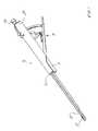
- FIG. 1is a top perspective of an inserter in accordance with one embodiment of the present invention releasably attached to and expandable interbody fusion device, shown unexpanded.
- FIG. 2is an exploded perspective view of the distal end of the inserter of FIG. 1 .
- FIG. 3is an enlarged view of the exploded portion of FIG. 2 .
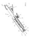
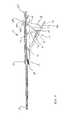
- FIG. 4is a longitudinal cross-sectional view of the inserter of FIG. 1 .
- FIG. 5is a top perspective view of an insert used in an expandable spinal interbody fusion device of the subject invention.
- FIG. 6is a bottom perspective view of the insert of FIG. 5 .
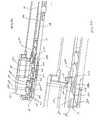
- FIG. 7is a partial perspective cross sectional view of the inserter of FIG. 1 releasably attached to an expandable interbody fusion device with a first insert of FIG. 5 having been inserted therein.
- FIG. 8 ais a partial side perspective view of the inserter and expandable interbody fusion device bottom of FIG. 7 showing a second insert entering the interbody fusion device at the proximal end and below the first insert.
- FIG. 8 bis an enlarged view of a portion of FIG. 8 a showing the relative positions of the first and second inserts.
- FIG. 9is a partial side perspective view of the inserter and expandable interbody fusion device of FIG. 8 a showing the second insert fully inserted into the interbody fusion device.
- FIG. 10is a proximal perspective view of an expanded spinal interbody fusion device with a guide pin releasably connected thereto subsequent to the inserter having been the detached from the guide pin with inserts not being shown for clarity.
- inserter 10is shown for use in expanding in situ a spinal implant, such as an interbody fusion device 100 , and for inserting inserts into the expanded device 100 .
- the expandable interbody fusion device 100includes a first element, such as superior endplate 112 and a second element, such as inferior endplate 114 , as shown in FIGS. 2-3 .
- the height across the superior and inferior endplates 112 , 114 in the unexpanded condition as illustrated in FIG. 1is less than the normal anatomic height of a typical intradiscal space.
- the inventioncontemplates expanding the interbody fusion device 100 by the inserter 10 to ultimately restore the normal anatomic height of the disc space and thereafter inserting a series of inserts, such as interlocking inserts 200 , as will be described, to form a stack of inserts 200 between the expanded superior and inferior endplates.
- the superior endplate 112is elongate and comprises a hub 116 that is sized and configured to fit within a cavity 118 of the inferior endplate 114 for telescoping movement therewithin upon expansion.
- the lower surface 120 of the hub 116includes a shaped configuration defined by insert mating features 122 (see FIG. 7 ) that are substantially identical to the mating features on the lower surface of each insert 200 , as will be described.
- the superior endplate 112includes a graft chamber defined by an opening 124 extending therethrough and inferior endplate 114 includes a graft chamber defined by an opening 126 extending therethrough for receipt of a suitable bone filler or bone graft to promote fusion between opposing vertebral bodies of a spine.
- interbody fusion device 100Further details of interbody fusion device 100 are described in commonly assigned U.S. patent application Ser. No. 13/795,054 entitled “Expandable Interbody Fusion Device with Graft Chambers”, filed on Mar. 12, 2013 (“the '054 Application”) and incorporated herein by reference.
- the insert 100is elongate and has an upper surface 202 and a lower surface 204 , both of which are generally planar so that the inserts can form a stable stack within the interbody fusion device 10 upon expansion.
- Insert 200includes a trailing rear end 206 and a leading front end 208 .
- the rear end 206is formed substantially in the form of a horseshoe, with a pair of spaced opposing arms 212 and 214 defining an open rearward facing generally U-shaped opening 216 .
- the surface 218 between the upper surface 202 and the lower surface 204 at the base of opening 216defines a pushing surface 218 for receipt of a driver of inserter 10 , as will be described.
- each insert 200The opening 216 at the rear end of each insert 200 is provided to allow bone graft material to flow into the device 100 through the insert openings 216 and into the openings 124 and 126 extending through the superior endplate 112 and the inferior endplate 114 , respectively.
- the rear end 206includes a flat surface 212 a and 214 a , respectively at the free end of each arm 212 and 214 and a flat surface 208 a on the leading front end 208 of the insert 200 .
- the insert 200includes several features for interlocking engagement to the hub 116 and to adjacent inserts 100 in a complementary interlocking mating interface.
- One particular featureincludes a series of locking elements defined by resiliently deflectable prongs 220 that project outwardly above the upper surface 202 of the insert 200 in the direction of expansion of device 100 .
- a complementary series of locking surfaces 222are defined in the lower surface 204 of the insert 200 for resilient engagement with the prongs 220 as inserts are inserted into device 100 to form a stack.
- the lower surface 204 of each insert 200 as shown in FIGS. 5 and 6also defines a T-slot configuration 224 for mating with a T-bar configuration 226 on the upper surface 202 of a successive insert 100 .
- prongs 220there are two prongs 220 extending generally linearly and substantially centrally along the elongate longitudinal direction adjacent the front end 208 of insert 200 .
- the structure and function of insert 200 and the prongs 220 and locking surfaces 222are more fully described in the '054 Application.
- the inserts 200 described hereindo not function to assist in the separation of superior endplate 112 and inferior endplate 114 or any subsequent inserts 200 inserted into interbody fusion device 100 as that lifting and function is provided by inserter 10 .
- Inserter 10comprises an elongate barrel 12 having a distal end 12 a and a proximal end 12 b .
- a trigger actuator 14 to effect expansion of device 100 and insertion of inserts 200 into device 100 after expansionis provided at the proximal end 12 b of barrel 12 .
- a cartridge 15 supported by barrel 12 on the underside thereofcontains a plurality of inserts 200 to provide a supply of inserts 204 inserting into device 100 by inserter 10 .
- the distal end 12 ais shown in exploded detail in FIGS. 2-3 .
- the barrel 12includes a lower track 16 and an upper track cover 18 .
- An elongate guide pin 20is supported by barrel 12 , the distal end 20 a of the guide pin 20 being threaded for releasable threaded engagement into a suitable threaded opening in the proximal end of the inferior endplate 114 .
- the proximal end 20 b of guide pin 20is provided with a threaded knob 22 for compressing the barrel 12 and thereby the inserter to the device 100 .
- the track cover 18in one arrangement, includes a pair of opposing tabs 18 a that engage corresponding notches 128 at the proximal end of the inferior endplate 114 to assist in rigidly securing the barrel 12 to the device 100 . It should be appreciated that other securement structure may be used to releasably attach the barrel 12 and thereby inserter 10 to the device 100 .
- the distal end 12 a of barrel 12supports a lifting platform 24 and an elevator 26 .
- the lifting platform 24is coupled at its proximal end 24 a by a boss 24 b or other suitable projection to a lifting platform link 28 .
- the boss 24 bis suitably received and retained in opening 28 a at the distal end of link 28 .
- the lifting platform 24is axially translatable relative to elevator 26 upon axial translational movement of link 28 which is coupled to an actuator, such as trigger actuator 14 at its proximal end, as will be described.
- Link 28is supported by track 16 for translational movement within a track channel 16 a extending axially along track 16 .
- Inserts 200are movably supported in a linear array on link 28 within the channel 16 a . It should be appreciated that actuators other than trigger actuators may be used with the inserter 10 described herein.
- Elevator 26comprises a proximal end 26 a and a distal projecting end 26 b .
- the proximal end 26 ais suitably affixed to the track 16 and, in the particular arrangement being described, remains in a fixed position relative to lifting platform 24 and inferior endplate 114 as lifting platform is translationally moved.
- the proximal end 26 adefines a channel 26 c for receipt of the proximal end 24 a of lifting platform 24 .
- the lifting platform 24 and elevator 26may in one arrangement be a disposable component and replaced by a new unused lifting platform 24 and elevator 26 for subsequent procedures.
- the distal projecting end 26 b of elevator 26includes a lower substantially flat surface 26 c and an upper surface 26 d , generally parallel to lower surface 26 c .
- Projecting end 26 bis configured to extend within inferior endplate 114 with lower surface 26 c supported by an interior surface 114 a (see FIG. 7 ).
- Upper surface 26 dis formed to have a series of axially extending ramp surfaces 26 e extending therewithin, three such ramp surfaces 26 e being illustrated.
- Lifting platform 24includes at its distal end 24 b an upper substantially flat surface 24 c and a lower surface 24 d , generally parallel to upper surface 24 c .
- Upper surface 24 cis configured to engage and support surface 205 at the underside of insert 200 (see FIG.
- Lower surface 24 dis formed to have a series of axially extending ramps 24 e , three of which are shown.
- Ramps 24 e projecting downwardly from lifting platform 24 and ramp surfaces 26 e extending within elevator 26are configured to have suitably inclined surfaces such that upon axial translational movement of lifting platform 24 relative to elevator 26 ramps 24 e engage ramp surfaces 26 e to cause lifting platform 24 to move upwardly and separate from elevator 26 .
- Lifting platform link 28includes thereon an upper surface 28 a on which the inserts 200 are movably supported in a linear array.
- Link 28includes a spring element 28 b having an inclined surface for engaging an insert 200 and moving such insert upwardly into an insertion position from track 16 during axial transit along link 28 .
- a pair of cantilevered spring projections 28 d and 28 emay be spaced axially along link 20 in a manner to substantially prevent retrograde movement of inserts 200 along link 28 .
- Barrel 12further supports a driver 30 for axial translational movement within the barrel 12 .
- the proximal end of driver 30is coupled to trigger actuator 14 to effect translational movement of the driver, as will be described.
- the distal end of driver 30comprises a pushing surface 30 a sized and configured to enter into the opening 216 of an insert 200 to engage pushing surface 218 and push the insert 200 into the device 100 upon axial distal movement of driver 30 .
- Trigger actuator 14comprises a bar linkage mechanism 31 comprising a first bar 32 and a second bar 34 .
- the lower end of each bar 32 and 34is pivotally connected to a handle 36 by a pivot pin 38 .
- Pin 38slides within a cam track 40 supported on handle 36 .
- the upper end of bar 32is pivotally connected to the proximal end of driver 38 pivot pin 42 .
- the upper end of bar 34is pivotally connected to the proximal end 12 b of barrel 12 by a pivot pin 44 .
- Handle 36is pivotally connected to barrel 12 by a pivot pin 46 .
- a curved cam member 48is attached at its lower end 48 a to handle 36 with upper end 48 b extending though barrel 12 .
- Cam member 48upon squeezing movement of the handle 36 toward barrel 12 engages a cam following surface 50 on barrel 12 to initially pull lifting platform link proximally.
- the bar linkage mechanism 31 of the trigger actuator 14is structured to move lifting platform link 28 and driver 30 independently of each other and with suitable time delays between such movements based on the configuration of the cam track 40 .
- the driver 30is returned to its original starting position when the handle 36 is released.
- FIG. 7illustrates a condition of the expansion of device 100 wherein a first insert 200 has been positioned between superior endplate 112 and inferior endplate 114 with prongs 220 suitably interlockingly engaging the mating features 122 at the lower surface of hub 116 .
- a subsequent insert 200 ais shown on spring element 28 b with the insert 200 a having been lifted by spring element 28 b into an insertion position from channel 16 a of track 16 during axial advancement distally by driver 30 .
- the ramps 24 e of lifting platform 24are not deployed relative to ramp surfaces 26 e of elevator 26 .
- Upper surface 24 c of lifting platform 24is in contact with and supports the underside surface 205 of insert 200 .
- lifting platform link 28is translated proximally causing ramps 24 e to engage and ride upwardly along ramp surfaces 26 e of elevator 26 thereby causing during such translational movement the lifting platform 24 to move upwardly and away from elevator 26 .
- Such movementlifts insert 200 together with interlocked superior endplate 112 in the direction of expansion an incremental distance slightly greater than the thickness of insert 200 a .
- trigger actuator 14With the bar linkage mechanism 31 of trigger actuator 14 configured to temporarily hold this position for a certain period of time, continued operation of trigger actuator 14 moves driver 30 distally until the pushing surface 30 a of driver 30 causes the front end 208 a of subsequent insert 200 a to enter device 100 between lower surface 204 of a previously inserted insert 200 and inferior ledge 114 b of the inferior endplate 114 , as shown in FIGS. 8 a and 8 b .
- continued operation of trigger actuator 14causes lifting platform link 28 to translate distally causing ramps 24 e to slide downwardly along ramp surfaces 26 e thereby retracting lifting platform 24 toward elevator 26 .
- trigger actuator 14causes driver 30 to move axially distally pushing insert 200 a fully into device 100 with little further resistance until the prongs 220 engage locking surfaces 222 .
- prongs 220suitably interlock with locking surfaces 222 of previously inserted insert 200 .
- handle 36is released the driver 30 is drawn proximally a sufficient distance within barrel 12 to be positioned to receive another insert 200 b supported within track channel 16 a , if necessary.
- distance Dmay be a minimum of approximately 2-3 mm.
- the guide pin 20may remain releasably connected to expanded device 100 to serve as a locator for subsequent attachment to an apparatus containing suitable bone growth material to assist in the delivery of such material into a channel 114 c of inferior endplate 114 through which inserts 200 were inserted.
- inserter 10and the method of expanding an interbody fusion device 100 and inserting thereinto one or more inserts 200 with reference to device 100 wherein a first insert 200 has been positioned between superior endplate 112 and inferior endplate 114
- the inserter 10 and methodmay also be used to introduce insert 200 initially between superior endplate 112 and inferior endplate 114 .
- lifting platform 24has been described herein as being movable axially relative to a fixed elevator 26 , it should be appreciated that lifting platform 24 may be held in a fixed axial position while the elevator 26 is moved axially relative thereto.
- the illustrated embodimentshave been directed particularly to interbody fusion of the spine, the expandable devices and inserts disclosed herein may be used in other applications that require distraction of tissue surfaces, such as, for example, vertebral compression fracture treatments. Modifications in size may be necessary depending upon the body space being distracted.
Landscapes
- Health & Medical Sciences (AREA)
- Engineering & Computer Science (AREA)
- Biomedical Technology (AREA)
- Orthopedic Medicine & Surgery (AREA)
- Neurology (AREA)
- Transplantation (AREA)
- Heart & Thoracic Surgery (AREA)
- Oral & Maxillofacial Surgery (AREA)
- Cardiology (AREA)
- Vascular Medicine (AREA)
- Life Sciences & Earth Sciences (AREA)
- Animal Behavior & Ethology (AREA)
- General Health & Medical Sciences (AREA)
- Public Health (AREA)
- Veterinary Medicine (AREA)
- Physical Education & Sports Medicine (AREA)
- Prostheses (AREA)
Abstract
Description
Claims (26)
Priority Applications (1)
| Application Number | Priority Date | Filing Date | Title |
|---|---|---|---|
| US14/716,319US9545313B2 (en) | 2013-03-13 | 2015-05-19 | Apparatus and method for expanding opposing body tissue |
Applications Claiming Priority (3)
| Application Number | Priority Date | Filing Date | Title |
|---|---|---|---|
| US13/799,792US8828019B1 (en) | 2013-03-13 | 2013-03-13 | Inserter for expanding an expandable interbody fusion device |
| US14/466,214US9039767B2 (en) | 2013-03-13 | 2014-08-22 | Method and inserter for interbody fusion |
| US14/716,319US9545313B2 (en) | 2013-03-13 | 2015-05-19 | Apparatus and method for expanding opposing body tissue |
Related Parent Applications (1)
| Application Number | Title | Priority Date | Filing Date |
|---|---|---|---|
| US14/466,214ContinuationUS9039767B2 (en) | 2013-03-13 | 2014-08-22 | Method and inserter for interbody fusion |
Publications (2)
| Publication Number | Publication Date |
|---|---|
| US20150335442A1 US20150335442A1 (en) | 2015-11-26 |
| US9545313B2true US9545313B2 (en) | 2017-01-17 |
Family
ID=51455113
Family Applications (3)
| Application Number | Title | Priority Date | Filing Date |
|---|---|---|---|
| US13/799,792ActiveUS8828019B1 (en) | 2013-03-13 | 2013-03-13 | Inserter for expanding an expandable interbody fusion device |
| US14/466,214ActiveUS9039767B2 (en) | 2013-03-13 | 2014-08-22 | Method and inserter for interbody fusion |
| US14/716,319Expired - Fee RelatedUS9545313B2 (en) | 2013-03-13 | 2015-05-19 | Apparatus and method for expanding opposing body tissue |
Family Applications Before (2)
| Application Number | Title | Priority Date | Filing Date |
|---|---|---|---|
| US13/799,792ActiveUS8828019B1 (en) | 2013-03-13 | 2013-03-13 | Inserter for expanding an expandable interbody fusion device |
| US14/466,214ActiveUS9039767B2 (en) | 2013-03-13 | 2014-08-22 | Method and inserter for interbody fusion |
Country Status (3)
| Country | Link |
|---|---|
| US (3) | US8828019B1 (en) |
| EP (1) | EP2967917B1 (en) |
| WO (1) | WO2014163936A2 (en) |
Cited By (6)
| Publication number | Priority date | Publication date | Assignee | Title |
|---|---|---|---|---|
| US10179054B2 (en) | 2008-02-06 | 2019-01-15 | Jeffrey B. Kleiner | Spinal fusion cage system with inserter |
| US10195053B2 (en) | 2009-09-18 | 2019-02-05 | Spinal Surgical Strategies, Llc | Bone graft delivery system and method for using same |
| US10201355B2 (en) | 2009-02-06 | 2019-02-12 | Kleiner Intellectual Property, Llc | Angled surgical tool for removing tissue from within an intervertebral space |
| US10245159B1 (en) | 2009-09-18 | 2019-04-02 | Spinal Surgical Strategies, Llc | Bone graft delivery system and method for using same |
| US10973656B2 (en) | 2009-09-18 | 2021-04-13 | Spinal Surgical Strategies, Inc. | Bone graft delivery system and method for using same |
| US11666455B2 (en) | 2009-09-18 | 2023-06-06 | Spinal Surgical Strategies, Inc., A Nevada Corporation | Bone graft delivery devices, systems and kits |
Families Citing this family (59)
| Publication number | Priority date | Publication date | Assignee | Title |
|---|---|---|---|---|
| US6793678B2 (en) | 2002-06-27 | 2004-09-21 | Depuy Acromed, Inc. | Prosthetic intervertebral motion disc having dampening |
| US9737414B2 (en) | 2006-11-21 | 2017-08-22 | Vertebral Technologies, Inc. | Methods and apparatus for minimally invasive modular interbody fusion devices |
| WO2008070863A2 (en) | 2006-12-07 | 2008-06-12 | Interventional Spine, Inc. | Intervertebral implant |
| US8900307B2 (en) | 2007-06-26 | 2014-12-02 | DePuy Synthes Products, LLC | Highly lordosed fusion cage |
| EP2237748B1 (en) | 2008-01-17 | 2012-09-05 | Synthes GmbH | An expandable intervertebral implant |
| US8936641B2 (en) | 2008-04-05 | 2015-01-20 | DePuy Synthes Products, LLC | Expandable intervertebral implant |
| US20210378834A1 (en) | 2008-05-22 | 2021-12-09 | Spinal Surgical Strategies, Inc., A Nevada Corporation D/B/A Kleiner Device Labs | Spinal fusion cage system with inserter |
| US8366748B2 (en) | 2008-12-05 | 2013-02-05 | Kleiner Jeffrey | Apparatus and method of spinal implant and fusion |
| US9526620B2 (en) | 2009-03-30 | 2016-12-27 | DePuy Synthes Products, Inc. | Zero profile spinal fusion cage |
| KR101687435B1 (en) | 2009-07-06 | 2016-12-19 | 신세스 게엠바하 | Expandable fixation assemblies |
| US9629729B2 (en) | 2009-09-18 | 2017-04-25 | Spinal Surgical Strategies, Llc | Biological delivery system with adaptable fusion cage interface |
| US8979860B2 (en) | 2010-06-24 | 2015-03-17 | DePuy Synthes Products. LLC | Enhanced cage insertion device |
| US8623091B2 (en) | 2010-06-29 | 2014-01-07 | DePuy Synthes Products, LLC | Distractible intervertebral implant |
| US20120078372A1 (en) | 2010-09-23 | 2012-03-29 | Thomas Gamache | Novel implant inserter having a laterally-extending dovetail engagement feature |
| DE102010047901B4 (en)* | 2010-10-11 | 2019-01-10 | Heinrich Böhm | Implant for the spine and operating instrument |
| US9402732B2 (en) | 2010-10-11 | 2016-08-02 | DePuy Synthes Products, Inc. | Expandable interspinous process spacer implant |
| US9265620B2 (en) | 2011-03-18 | 2016-02-23 | Raed M. Ali, M.D., Inc. | Devices and methods for transpedicular stabilization of the spine |
| EP2685921B1 (en) | 2011-03-18 | 2019-03-13 | Raed M. Ali, M.D., Inc. | Transpedicular access to intervertebral spaces and related spinal fusion systems and methods |
| US9248028B2 (en) | 2011-09-16 | 2016-02-02 | DePuy Synthes Products, Inc. | Removable, bone-securing cover plate for intervertebral fusion cage |
| US9510953B2 (en) | 2012-03-16 | 2016-12-06 | Vertebral Technologies, Inc. | Modular segmented disc nucleus implant |
| WO2013149134A2 (en)* | 2012-03-30 | 2013-10-03 | Olympus Biotech Corporation | Alif spinal implant |
| EP2877127B1 (en) | 2012-07-26 | 2019-08-21 | Synthes GmbH | Expandable implant |
| US9717601B2 (en) | 2013-02-28 | 2017-08-01 | DePuy Synthes Products, Inc. | Expandable intervertebral implant, system, kit and method |
| US9522070B2 (en) | 2013-03-07 | 2016-12-20 | Interventional Spine, Inc. | Intervertebral implant |
| US10687962B2 (en) | 2013-03-14 | 2020-06-23 | Raed M. Ali, M.D., Inc. | Interbody fusion devices, systems and methods |
| US9861495B2 (en) | 2013-03-14 | 2018-01-09 | Raed M. Ali, M.D., Inc. | Lateral interbody fusion devices, systems and methods |
| WO2014185989A2 (en)* | 2013-05-14 | 2014-11-20 | Spine View, Inc. | Intervertebral devices and related methods |
| AU2014268740B2 (en) | 2013-05-20 | 2018-04-26 | K2M, Inc. | Adjustable implant and insertion tool |
| US11065132B2 (en) | 2014-03-06 | 2021-07-20 | Spine Wave, Inc. | Method of expanding a space between opposing tissue surfaces |
| US9445921B2 (en) | 2014-03-06 | 2016-09-20 | Spine Wave, Inc. | Device for expanding and supporting body tissue |
| JP6100982B1 (en)* | 2014-03-06 | 2017-03-22 | スパイン・ウェーヴ・インコーポレイテッド | Inserter for expandable spinal interbody fusion device |
| US9439783B2 (en) | 2014-03-06 | 2016-09-13 | Spine Wave, Inc. | Inserter for expanding body tissue |
| US9265623B2 (en) | 2014-03-06 | 2016-02-23 | Spine Wave, Inc. | Method of expanding a spinal interbody fusion device |
| US9107766B1 (en)* | 2014-03-06 | 2015-08-18 | Spine Wave, Inc. | Expandable spinal interbody fusion device and inserter |
| US9585762B2 (en) | 2014-10-09 | 2017-03-07 | K2M, Inc. | Expandable spinal interbody spacer and method of use |
| WO2016077606A1 (en) | 2014-11-12 | 2016-05-19 | Medivest, Llc | Spinal spacing implant, spinal spacer assembly, expander and insertion instrument, kit and methods of assembly and use |
| US11426290B2 (en) | 2015-03-06 | 2022-08-30 | DePuy Synthes Products, Inc. | Expandable intervertebral implant, system, kit and method |
| WO2016200691A2 (en)* | 2015-06-11 | 2016-12-15 | Spine Wave, Inc. | Inserter for expanding body tissue |
| WO2016200631A1 (en)* | 2015-06-11 | 2016-12-15 | Spine Wave, Inc. | Device for expanding and supporting body tissue |
| US9913727B2 (en) | 2015-07-02 | 2018-03-13 | Medos International Sarl | Expandable implant |
| USD797290S1 (en) | 2015-10-19 | 2017-09-12 | Spinal Surgical Strategies, Llc | Bone graft delivery tool |
| US10426631B2 (en)* | 2016-02-20 | 2019-10-01 | Seth K. WILLIAMS | System and method for spine fusion using an expandable cage |
| US10004608B2 (en) | 2016-02-26 | 2018-06-26 | K2M, Inc. | Insertion instrument for expandable spinal implants |
| US11510788B2 (en) | 2016-06-28 | 2022-11-29 | Eit Emerging Implant Technologies Gmbh | Expandable, angularly adjustable intervertebral cages |
| EP3474784A2 (en) | 2016-06-28 | 2019-05-01 | Eit Emerging Implant Technologies GmbH | Expandable and angularly adjustable intervertebral cages with articulating joint |
| US10537436B2 (en) | 2016-11-01 | 2020-01-21 | DePuy Synthes Products, Inc. | Curved expandable cage |
| US10888433B2 (en) | 2016-12-14 | 2021-01-12 | DePuy Synthes Products, Inc. | Intervertebral implant inserter and related methods |
| EP3357459A1 (en) | 2017-02-03 | 2018-08-08 | Spinal Surgical Strategies, LLC | Bone graft delivery device with positioning handle |
| US10398563B2 (en) | 2017-05-08 | 2019-09-03 | Medos International Sarl | Expandable cage |
| US11344424B2 (en) | 2017-06-14 | 2022-05-31 | Medos International Sarl | Expandable intervertebral implant and related methods |
| US10940016B2 (en) | 2017-07-05 | 2021-03-09 | Medos International Sarl | Expandable intervertebral fusion cage |
| US11446156B2 (en) | 2018-10-25 | 2022-09-20 | Medos International Sarl | Expandable intervertebral implant, inserter instrument, and related methods |
| GB201818850D0 (en)* | 2018-11-19 | 2019-01-02 | Axis Spine Tech Ltd | Intervertebral devices |
| US11426286B2 (en) | 2020-03-06 | 2022-08-30 | Eit Emerging Implant Technologies Gmbh | Expandable intervertebral implant |
| US11850160B2 (en) | 2021-03-26 | 2023-12-26 | Medos International Sarl | Expandable lordotic intervertebral fusion cage |
| US11752009B2 (en) | 2021-04-06 | 2023-09-12 | Medos International Sarl | Expandable intervertebral fusion cage |
| WO2023285675A1 (en) | 2021-07-16 | 2023-01-19 | Blue Ocean Spine Gmbh | Adjustable intervertebral cage, associated instrument and manufacturing process therefor |
| US12090064B2 (en) | 2022-03-01 | 2024-09-17 | Medos International Sarl | Stabilization members for expandable intervertebral implants, and related systems and methods |
| US12324749B2 (en)* | 2022-07-25 | 2025-06-10 | DePuy Synthes Products, Inc. | Impaction handle for implanting a tibial tray of an orthopaedic knee prosthesis and associated method of making the same |
Citations (90)
| Publication number | Priority date | Publication date | Assignee | Title |
|---|---|---|---|---|
| US3486505A (en) | 1967-05-22 | 1969-12-30 | Gordon M Morrison | Orthopedic surgical instrument |
| US4524766A (en) | 1982-01-07 | 1985-06-25 | Petersen Thomas D | Surgical knee alignment method and system |
| US4683476A (en) | 1984-06-22 | 1987-07-28 | Benson S.A. | Drawing machine having automatically replaced writing members and apparatus therefor |
| US4736738A (en) | 1984-07-09 | 1988-04-12 | Matej Lipovsek | Instrument kit and procedure for performing posterior lumbar interbody fusion |
| US4743493A (en) | 1986-10-06 | 1988-05-10 | Spire Corporation | Ion implantation of plastics |
| US4755797A (en) | 1986-08-14 | 1988-07-05 | Nittan Co., Ltd. | Fire alarm apparatus |
| US4863476A (en) | 1986-08-29 | 1989-09-05 | Shepperd John A N | Spinal implant |
| US4888024A (en) | 1985-11-08 | 1989-12-19 | Powlan Roy Y | Prosthetic device and method of fixation within the medullary cavity of bones |
| FR2639823A1 (en) | 1988-12-06 | 1990-06-08 | Garcia Alain | Replacement of the nucleus of the intervertebral disc by a polyurethane polymerised in situ |
| US5059193A (en) | 1989-11-20 | 1991-10-22 | Spine-Tech, Inc. | Expandable spinal implant and surgical method |
| US5192327A (en) | 1991-03-22 | 1993-03-09 | Brantigan John W | Surgical prosthetic implant for vertebrae |
| US5192326A (en) | 1990-12-21 | 1993-03-09 | Pfizer Hospital Products Group, Inc. | Hydrogel bead intervertebral disc nucleus |
| US5197971A (en) | 1990-03-02 | 1993-03-30 | Bonutti Peter M | Arthroscopic retractor and method of using the same |
| US5298254A (en) | 1989-09-21 | 1994-03-29 | Osteotech, Inc. | Shaped, swollen demineralized bone and its use in bone repair |
| EP0621020A1 (en) | 1993-04-21 | 1994-10-26 | SULZER Medizinaltechnik AG | Intervertebral prosthesis and method of implanting such a prosthesis |
| US5431658A (en) | 1994-02-14 | 1995-07-11 | Moskovich; Ronald | Facilitator for vertebrae grafts and prostheses |
| FR2719763A1 (en) | 1994-05-11 | 1995-11-17 | Jean Taylor | Vertebral implant. |
| US5505732A (en) | 1988-06-13 | 1996-04-09 | Michelson; Gary K. | Apparatus and method of inserting spinal implants |
| US5514180A (en) | 1994-01-14 | 1996-05-07 | Heggeness; Michael H. | Prosthetic intervertebral devices |
| US5522899A (en) | 1988-06-28 | 1996-06-04 | Sofamor Danek Properties, Inc. | Artificial spinal fusion implants |
| US5571109A (en) | 1993-08-26 | 1996-11-05 | Man Ceramics Gmbh | System for the immobilization of vertebrae |
| US5591235A (en) | 1995-03-15 | 1997-01-07 | Kuslich; Stephen D. | Spinal fixation device |
| US5645599A (en) | 1994-07-26 | 1997-07-08 | Fixano | Interspinal vertebral implant |
| US5756127A (en) | 1996-10-29 | 1998-05-26 | Wright Medical Technology, Inc. | Implantable bioresorbable string of calcium sulfate beads |
| US5766252A (en) | 1995-01-24 | 1998-06-16 | Osteonics Corp. | Interbody spinal prosthetic implant and method |
| US5836948A (en) | 1997-01-02 | 1998-11-17 | Saint Francis Medical Technologies, Llc | Spine distraction implant and method |
| US5860977A (en) | 1997-01-02 | 1999-01-19 | Saint Francis Medical Technologies, Llc | Spine distraction implant and method |
| WO1999002214A1 (en) | 1997-07-09 | 1999-01-21 | Tegementa, L.L.C. | Interbody device and method for treatment of osteoporotic vertebral collapse |
| US5891147A (en) | 1996-06-25 | 1999-04-06 | Sdgi Holdings, Inc. | Minimally invasive spinal surgical methods & instruments |
| US5951553A (en) | 1997-07-14 | 1999-09-14 | Sdgi Holdings, Inc. | Methods and apparatus for fusionless treatment of spinal deformities |
| US5980522A (en) | 1994-07-22 | 1999-11-09 | Koros; Tibor | Expandable spinal implants |
| US6033411A (en) | 1997-10-14 | 2000-03-07 | Parallax Medical Inc. | Precision depth guided instruments for use in vertebroplasty |
| US6045579A (en) | 1997-05-01 | 2000-04-04 | Spinal Concepts, Inc. | Adjustable height fusion device |
| US6066154A (en) | 1994-01-26 | 2000-05-23 | Kyphon Inc. | Inflatable device for use in surgical protocol relating to fixation of bone |
| US6110179A (en) | 1998-03-02 | 2000-08-29 | Benoist Girard Sas | Prosthesis inserter |
| US6110210A (en) | 1999-04-08 | 2000-08-29 | Raymedica, Inc. | Prosthetic spinal disc nucleus having selectively coupled bodies |
| US6159244A (en) | 1999-07-30 | 2000-12-12 | Suddaby; Loubert | Expandable variable angle intervertebral fusion implant |
| US6159211A (en) | 1998-10-22 | 2000-12-12 | Depuy Acromed, Inc. | Stackable cage system for corpectomy/vertebrectomy |
| US6183517B1 (en) | 1998-12-16 | 2001-02-06 | Loubert Suddaby | Expandable intervertebral fusion implant and applicator |
| US6190414B1 (en) | 1996-10-31 | 2001-02-20 | Surgical Dynamics Inc. | Apparatus for fusion of adjacent bone structures |
| US6200347B1 (en) | 1999-01-05 | 2001-03-13 | Lifenet | Composite bone graft, method of making and using same |
| US6241771B1 (en) | 1997-08-13 | 2001-06-05 | Cambridge Scientific, Inc. | Resorbable interbody spinal fusion devices |
| US6273916B1 (en) | 1999-09-02 | 2001-08-14 | Cook Incorporated | Method and apparatus for strengthening vertebral bodies |
| US6279916B1 (en) | 1995-06-29 | 2001-08-28 | Friedhelm Stecher | Flat gasket and method of producing the same |
| US6287309B1 (en) | 1997-09-23 | 2001-09-11 | Dimso (Distribution Medicale Du Sudouest) | Screw and plate system for backbone osteosynthesis |
| US6287308B1 (en) | 1997-07-14 | 2001-09-11 | Sdgi Holdings, Inc. | Methods and apparatus for fusionless treatment of spinal deformities |
| US6290724B1 (en) | 1998-05-27 | 2001-09-18 | Nuvasive, Inc. | Methods for separating and stabilizing adjacent vertebrae |
| US20020026195A1 (en) | 2000-04-07 | 2002-02-28 | Kyphon Inc. | Insertion devices and method of use |
| US6387130B1 (en) | 1999-04-16 | 2002-05-14 | Nuvasive, Inc. | Segmented linked intervertebral implant systems |
| US6395034B1 (en) | 1999-11-24 | 2002-05-28 | Loubert Suddaby | Intervertebral disc prosthesis |
| US6402750B1 (en) | 2000-04-04 | 2002-06-11 | Spinlabs, Llc | Devices and methods for the treatment of spinal disorders |
| US6419705B1 (en) | 1999-06-23 | 2002-07-16 | Sulzer Spine-Tech Inc. | Expandable fusion device and method |
| US6432107B1 (en) | 2000-01-15 | 2002-08-13 | Bret A. Ferree | Enhanced surface area spinal fusion devices |
| US6436142B1 (en) | 1998-12-14 | 2002-08-20 | Phoenix Biomedical Corp. | System for stabilizing the vertebral column including deployment instruments and variable expansion inserts therefor |
| US20020147497A1 (en) | 2001-04-06 | 2002-10-10 | Integrated Vascular Systems, Inc. | Methods for treating spinal discs |
| US6478800B1 (en) | 2000-05-08 | 2002-11-12 | Depuy Acromed, Inc. | Medical installation tool |
| US20020177897A1 (en) | 2001-02-04 | 2002-11-28 | Michelson Gary K. | Instrumentation and method for inserting and deploying and expandable interbody spinal fusion implant |
| US6488710B2 (en) | 1999-07-02 | 2002-12-03 | Petrus Besselink | Reinforced expandable cage and method of deploying |
| US6500205B1 (en) | 2000-04-19 | 2002-12-31 | Gary K. Michelson | Expandable threaded arcuate interbody spinal fusion implant with cylindrical configuration during insertion |
| US6520993B2 (en) | 2000-12-29 | 2003-02-18 | Depuy Acromed, Inc. | Spinal implant |
| US6562074B2 (en) | 2001-10-17 | 2003-05-13 | Medicinelodge, Inc. | Adjustable bone fusion implant and method |
| US6595998B2 (en) | 2001-03-08 | 2003-07-22 | Spinewave, Inc. | Tissue distraction device |
| US20030171812A1 (en) | 2001-12-31 | 2003-09-11 | Ilan Grunberg | Minimally invasive modular support implant device and method |
| US6620196B1 (en) | 2000-08-30 | 2003-09-16 | Sdgi Holdings, Inc. | Intervertebral disc nucleus implants and methods |
| US6656178B1 (en) | 1999-07-28 | 2003-12-02 | Baat B.V. Engineering | Vertebral-column fusion devices and surgical methods |
| US20040030387A1 (en) | 2002-03-11 | 2004-02-12 | Landry Michael E. | Instrumentation and procedure for implanting spinal implant devices |
| US6726691B2 (en) | 1998-08-14 | 2004-04-27 | Kyphon Inc. | Methods for treating fractured and/or diseased bone |
| US6740093B2 (en) | 2000-02-28 | 2004-05-25 | Stephen Hochschuler | Method and apparatus for treating a vertebral body |
| US6837904B2 (en) | 2001-07-16 | 2005-01-04 | Spinecore, Inc. | Method of surgically treating scoliosis |
| US20050027364A1 (en) | 2003-08-01 | 2005-02-03 | Kim Daniel H. | Prosthetic intervertebral disc and methods for using the same |
| US6852095B1 (en) | 1997-07-09 | 2005-02-08 | Charles D. Ray | Interbody device and method for treatment of osteoporotic vertebral collapse |
| US6852126B2 (en) | 2000-07-17 | 2005-02-08 | Nuvasive, Inc. | Stackable interlocking intervertebral support system |
| US6997929B2 (en) | 2003-05-16 | 2006-02-14 | Spine Wave, Inc. | Tissue distraction device |
| US20060058880A1 (en) | 2004-08-25 | 2006-03-16 | Steve Wysocki | Expandable interbody fusion device |
| US20060129244A1 (en) | 2004-10-25 | 2006-06-15 | Alphaspine, Inc. | Expandable intervertebral spacer method and apparatus |
| US7118580B1 (en) | 1999-09-14 | 2006-10-10 | Spine Solutions Inc. | Instrument for inserting intervertebral implants |
| US20080154377A1 (en) | 2006-12-22 | 2008-06-26 | Voellmicke John C | Composite vertebral spacers and instrument |
| US20080172127A1 (en) | 2007-01-16 | 2008-07-17 | Mi4Spine, Llc | Minimally Invasive Interbody Device |
| US20080300059A1 (en) | 2005-09-09 | 2008-12-04 | Adiraju Srinivyasa M | Gaming Network Using Host-Configured Networking Protocols |
| US20080300598A1 (en)* | 2007-05-31 | 2008-12-04 | Spine Wave, Inc. | Expandable Interbody Fusion Device |
| US20090198339A1 (en) | 2008-02-06 | 2009-08-06 | Nuvasive, Inc. | Systems and methods for spinal fusion |
| US7591852B2 (en) | 2003-12-02 | 2009-09-22 | Alphatec Spine, Inc. | Vertebral body replacement cage assembly |
| US7722625B2 (en) | 2004-06-30 | 2010-05-25 | Depuy Products, Inc. | Modular bone clamp instrument |
| US20110184522A1 (en)* | 2010-01-27 | 2011-07-28 | Warsaw Orthopedic, Inc. | Modular interbody devices and methods of use |
| US8062375B2 (en) | 2009-10-15 | 2011-11-22 | Globus Medical, Inc. | Expandable fusion device and method of installation thereof |
| US20120158144A1 (en) | 2005-05-06 | 2012-06-21 | Ullrich Jr Peter F | Implant with critical ratio of load bearing surface area to central opening area |
| US8308805B2 (en) | 2010-03-16 | 2012-11-13 | Pinnacle Spine Group, Llc | Methods of delivering an implant to an intervertebral space |
| US8382842B2 (en) | 2009-05-14 | 2013-02-26 | Stout Medical Group, L.P. | Expandable support device and method of use |
| US20130090735A1 (en) | 2011-10-07 | 2013-04-11 | Daniel Ryan Mermuys | Intervertebral Implant |
| US8628578B2 (en) | 2011-12-19 | 2014-01-14 | Warsaw Orthopedic, Inc. | Expandable interbody implant and methods of use |
- 2013
- 2013-03-13USUS13/799,792patent/US8828019B1/enactiveActive
- 2014
- 2014-02-27WOPCT/US2014/019028patent/WO2014163936A2/enactiveApplication Filing
- 2014-02-27EPEP14779285.7Apatent/EP2967917B1/ennot_activeNot-in-force
- 2014-08-22USUS14/466,214patent/US9039767B2/enactiveActive
- 2015
- 2015-05-19USUS14/716,319patent/US9545313B2/ennot_activeExpired - Fee Related
Patent Citations (104)
| Publication number | Priority date | Publication date | Assignee | Title |
|---|---|---|---|---|
| US3486505A (en) | 1967-05-22 | 1969-12-30 | Gordon M Morrison | Orthopedic surgical instrument |
| US4524766A (en) | 1982-01-07 | 1985-06-25 | Petersen Thomas D | Surgical knee alignment method and system |
| US4683476A (en) | 1984-06-22 | 1987-07-28 | Benson S.A. | Drawing machine having automatically replaced writing members and apparatus therefor |
| US4736738A (en) | 1984-07-09 | 1988-04-12 | Matej Lipovsek | Instrument kit and procedure for performing posterior lumbar interbody fusion |
| US4888024A (en) | 1985-11-08 | 1989-12-19 | Powlan Roy Y | Prosthetic device and method of fixation within the medullary cavity of bones |
| US4755797A (en) | 1986-08-14 | 1988-07-05 | Nittan Co., Ltd. | Fire alarm apparatus |
| US4863476A (en) | 1986-08-29 | 1989-09-05 | Shepperd John A N | Spinal implant |
| US4743493A (en) | 1986-10-06 | 1988-05-10 | Spire Corporation | Ion implantation of plastics |
| US5505732A (en) | 1988-06-13 | 1996-04-09 | Michelson; Gary K. | Apparatus and method of inserting spinal implants |
| US5522899A (en) | 1988-06-28 | 1996-06-04 | Sofamor Danek Properties, Inc. | Artificial spinal fusion implants |
| FR2639823A1 (en) | 1988-12-06 | 1990-06-08 | Garcia Alain | Replacement of the nucleus of the intervertebral disc by a polyurethane polymerised in situ |
| US5439684A (en) | 1989-09-21 | 1995-08-08 | Osteotech, Inc. | Shaped, swollen demineralized bone and its use in bone repair |
| US5298254A (en) | 1989-09-21 | 1994-03-29 | Osteotech, Inc. | Shaped, swollen demineralized bone and its use in bone repair |
| US5059193A (en) | 1989-11-20 | 1991-10-22 | Spine-Tech, Inc. | Expandable spinal implant and surgical method |
| US5197971A (en) | 1990-03-02 | 1993-03-30 | Bonutti Peter M | Arthroscopic retractor and method of using the same |
| US5192326A (en) | 1990-12-21 | 1993-03-09 | Pfizer Hospital Products Group, Inc. | Hydrogel bead intervertebral disc nucleus |
| US5192327A (en) | 1991-03-22 | 1993-03-09 | Brantigan John W | Surgical prosthetic implant for vertebrae |
| EP0621020A1 (en) | 1993-04-21 | 1994-10-26 | SULZER Medizinaltechnik AG | Intervertebral prosthesis and method of implanting such a prosthesis |
| US5755797A (en) | 1993-04-21 | 1998-05-26 | Sulzer Medizinaltechnik Ag | Intervertebral prosthesis and a process for implanting such a prosthesis |
| US5702454A (en) | 1993-04-21 | 1997-12-30 | Sulzer Orthopadie Ag | Process for implanting an invertebral prosthesis |
| US5571109A (en) | 1993-08-26 | 1996-11-05 | Man Ceramics Gmbh | System for the immobilization of vertebrae |
| US5514180A (en) | 1994-01-14 | 1996-05-07 | Heggeness; Michael H. | Prosthetic intervertebral devices |
| US6066154A (en) | 1994-01-26 | 2000-05-23 | Kyphon Inc. | Inflatable device for use in surgical protocol relating to fixation of bone |
| US5431658A (en) | 1994-02-14 | 1995-07-11 | Moskovich; Ronald | Facilitator for vertebrae grafts and prostheses |
| FR2719763A1 (en) | 1994-05-11 | 1995-11-17 | Jean Taylor | Vertebral implant. |
| US5980522A (en) | 1994-07-22 | 1999-11-09 | Koros; Tibor | Expandable spinal implants |
| US5645599A (en) | 1994-07-26 | 1997-07-08 | Fixano | Interspinal vertebral implant |
| US5766252A (en) | 1995-01-24 | 1998-06-16 | Osteonics Corp. | Interbody spinal prosthetic implant and method |
| US5591235A (en) | 1995-03-15 | 1997-01-07 | Kuslich; Stephen D. | Spinal fixation device |
| US6279916B1 (en) | 1995-06-29 | 2001-08-28 | Friedhelm Stecher | Flat gasket and method of producing the same |
| US5891147A (en) | 1996-06-25 | 1999-04-06 | Sdgi Holdings, Inc. | Minimally invasive spinal surgical methods & instruments |
| US5756127A (en) | 1996-10-29 | 1998-05-26 | Wright Medical Technology, Inc. | Implantable bioresorbable string of calcium sulfate beads |
| US6190414B1 (en) | 1996-10-31 | 2001-02-20 | Surgical Dynamics Inc. | Apparatus for fusion of adjacent bone structures |
| US5836948A (en) | 1997-01-02 | 1998-11-17 | Saint Francis Medical Technologies, Llc | Spine distraction implant and method |
| US6074390A (en) | 1997-01-02 | 2000-06-13 | St. Francis Medical Technologies, Inc. | Spine distraction implant and method |
| US5860977A (en) | 1997-01-02 | 1999-01-19 | Saint Francis Medical Technologies, Llc | Spine distraction implant and method |
| US6045579A (en) | 1997-05-01 | 2000-04-04 | Spinal Concepts, Inc. | Adjustable height fusion device |
| WO1999002214A1 (en) | 1997-07-09 | 1999-01-21 | Tegementa, L.L.C. | Interbody device and method for treatment of osteoporotic vertebral collapse |
| US6852095B1 (en) | 1997-07-09 | 2005-02-08 | Charles D. Ray | Interbody device and method for treatment of osteoporotic vertebral collapse |
| US6287308B1 (en) | 1997-07-14 | 2001-09-11 | Sdgi Holdings, Inc. | Methods and apparatus for fusionless treatment of spinal deformities |
| US5951553A (en) | 1997-07-14 | 1999-09-14 | Sdgi Holdings, Inc. | Methods and apparatus for fusionless treatment of spinal deformities |
| US6241771B1 (en) | 1997-08-13 | 2001-06-05 | Cambridge Scientific, Inc. | Resorbable interbody spinal fusion devices |
| US6287309B1 (en) | 1997-09-23 | 2001-09-11 | Dimso (Distribution Medicale Du Sudouest) | Screw and plate system for backbone osteosynthesis |
| US6033411A (en) | 1997-10-14 | 2000-03-07 | Parallax Medical Inc. | Precision depth guided instruments for use in vertebroplasty |
| US6110179A (en) | 1998-03-02 | 2000-08-29 | Benoist Girard Sas | Prosthesis inserter |
| US6290724B1 (en) | 1998-05-27 | 2001-09-18 | Nuvasive, Inc. | Methods for separating and stabilizing adjacent vertebrae |
| US6726691B2 (en) | 1998-08-14 | 2004-04-27 | Kyphon Inc. | Methods for treating fractured and/or diseased bone |
| US6159211A (en) | 1998-10-22 | 2000-12-12 | Depuy Acromed, Inc. | Stackable cage system for corpectomy/vertebrectomy |
| US6436142B1 (en) | 1998-12-14 | 2002-08-20 | Phoenix Biomedical Corp. | System for stabilizing the vertebral column including deployment instruments and variable expansion inserts therefor |
| US6183517B1 (en) | 1998-12-16 | 2001-02-06 | Loubert Suddaby | Expandable intervertebral fusion implant and applicator |
| US6200347B1 (en) | 1999-01-05 | 2001-03-13 | Lifenet | Composite bone graft, method of making and using same |
| US6110210A (en) | 1999-04-08 | 2000-08-29 | Raymedica, Inc. | Prosthetic spinal disc nucleus having selectively coupled bodies |
| US6387130B1 (en) | 1999-04-16 | 2002-05-14 | Nuvasive, Inc. | Segmented linked intervertebral implant systems |
| US6419705B1 (en) | 1999-06-23 | 2002-07-16 | Sulzer Spine-Tech Inc. | Expandable fusion device and method |
| US6488710B2 (en) | 1999-07-02 | 2002-12-03 | Petrus Besselink | Reinforced expandable cage and method of deploying |
| US6656178B1 (en) | 1999-07-28 | 2003-12-02 | Baat B.V. Engineering | Vertebral-column fusion devices and surgical methods |
| US6159244A (en) | 1999-07-30 | 2000-12-12 | Suddaby; Loubert | Expandable variable angle intervertebral fusion implant |
| US6273916B1 (en) | 1999-09-02 | 2001-08-14 | Cook Incorporated | Method and apparatus for strengthening vertebral bodies |
| US7118580B1 (en) | 1999-09-14 | 2006-10-10 | Spine Solutions Inc. | Instrument for inserting intervertebral implants |
| US6395034B1 (en) | 1999-11-24 | 2002-05-28 | Loubert Suddaby | Intervertebral disc prosthesis |
| US6432107B1 (en) | 2000-01-15 | 2002-08-13 | Bret A. Ferree | Enhanced surface area spinal fusion devices |
| US6740093B2 (en) | 2000-02-28 | 2004-05-25 | Stephen Hochschuler | Method and apparatus for treating a vertebral body |
| US6402750B1 (en) | 2000-04-04 | 2002-06-11 | Spinlabs, Llc | Devices and methods for the treatment of spinal disorders |
| US20020026195A1 (en) | 2000-04-07 | 2002-02-28 | Kyphon Inc. | Insertion devices and method of use |
| US6500205B1 (en) | 2000-04-19 | 2002-12-31 | Gary K. Michelson | Expandable threaded arcuate interbody spinal fusion implant with cylindrical configuration during insertion |
| US6478800B1 (en) | 2000-05-08 | 2002-11-12 | Depuy Acromed, Inc. | Medical installation tool |
| US6852126B2 (en) | 2000-07-17 | 2005-02-08 | Nuvasive, Inc. | Stackable interlocking intervertebral support system |
| US20050149194A1 (en) | 2000-07-17 | 2005-07-07 | Nuvasive, Inc. | Stackable interlocking intervertebral support system |
| US6620196B1 (en) | 2000-08-30 | 2003-09-16 | Sdgi Holdings, Inc. | Intervertebral disc nucleus implants and methods |
| US6520993B2 (en) | 2000-12-29 | 2003-02-18 | Depuy Acromed, Inc. | Spinal implant |
| US20020177897A1 (en) | 2001-02-04 | 2002-11-28 | Michelson Gary K. | Instrumentation and method for inserting and deploying and expandable interbody spinal fusion implant |
| US20040019354A1 (en) | 2001-03-08 | 2004-01-29 | Wes Johnson | Tissue distraction device |
| US20040064144A1 (en) | 2001-03-08 | 2004-04-01 | Wes Johnson | Tissue distraction device |
| US20040220580A1 (en) | 2001-03-08 | 2004-11-04 | Wes Johnson | Tissue distraction device |
| US6595998B2 (en) | 2001-03-08 | 2003-07-22 | Spinewave, Inc. | Tissue distraction device |
| US20020147497A1 (en) | 2001-04-06 | 2002-10-10 | Integrated Vascular Systems, Inc. | Methods for treating spinal discs |
| US6837904B2 (en) | 2001-07-16 | 2005-01-04 | Spinecore, Inc. | Method of surgically treating scoliosis |
| US6648917B2 (en) | 2001-10-17 | 2003-11-18 | Medicinelodge, Inc. | Adjustable bone fusion implant and method |
| US6852129B2 (en) | 2001-10-17 | 2005-02-08 | Movdice Holding, Inc. | Adjustable bone fusion implant and method |
| US6562074B2 (en) | 2001-10-17 | 2003-05-13 | Medicinelodge, Inc. | Adjustable bone fusion implant and method |
| US6863673B2 (en) | 2001-10-17 | 2005-03-08 | Movdice Holding, Inc. | Methods for adjustable bone fusion implants |
| US20030171812A1 (en) | 2001-12-31 | 2003-09-11 | Ilan Grunberg | Minimally invasive modular support implant device and method |
| US20040030387A1 (en) | 2002-03-11 | 2004-02-12 | Landry Michael E. | Instrumentation and procedure for implanting spinal implant devices |
| US6997929B2 (en) | 2003-05-16 | 2006-02-14 | Spine Wave, Inc. | Tissue distraction device |
| US20050027364A1 (en) | 2003-08-01 | 2005-02-03 | Kim Daniel H. | Prosthetic intervertebral disc and methods for using the same |
| US7591852B2 (en) | 2003-12-02 | 2009-09-22 | Alphatec Spine, Inc. | Vertebral body replacement cage assembly |
| US7722625B2 (en) | 2004-06-30 | 2010-05-25 | Depuy Products, Inc. | Modular bone clamp instrument |
| US20060058880A1 (en) | 2004-08-25 | 2006-03-16 | Steve Wysocki | Expandable interbody fusion device |
| US20060058807A1 (en) | 2004-08-25 | 2006-03-16 | Michael Landry | Expandable interbody fusion device |
| US7931688B2 (en) | 2004-08-25 | 2011-04-26 | Spine Wave, Inc. | Expandable interbody fusion device |
| US20060129244A1 (en) | 2004-10-25 | 2006-06-15 | Alphaspine, Inc. | Expandable intervertebral spacer method and apparatus |
| US20120158144A1 (en) | 2005-05-06 | 2012-06-21 | Ullrich Jr Peter F | Implant with critical ratio of load bearing surface area to central opening area |
| US20080300059A1 (en) | 2005-09-09 | 2008-12-04 | Adiraju Srinivyasa M | Gaming Network Using Host-Configured Networking Protocols |
| US20080154377A1 (en) | 2006-12-22 | 2008-06-26 | Voellmicke John C | Composite vertebral spacers and instrument |
| US20080172127A1 (en) | 2007-01-16 | 2008-07-17 | Mi4Spine, Llc | Minimally Invasive Interbody Device |
| US20080300598A1 (en)* | 2007-05-31 | 2008-12-04 | Spine Wave, Inc. | Expandable Interbody Fusion Device |
| US7967867B2 (en) | 2007-05-31 | 2011-06-28 | Spine Wave, Inc. | Expandable interbody fusion device |
| US20090198339A1 (en) | 2008-02-06 | 2009-08-06 | Nuvasive, Inc. | Systems and methods for spinal fusion |
| US8382842B2 (en) | 2009-05-14 | 2013-02-26 | Stout Medical Group, L.P. | Expandable support device and method of use |
| US8062375B2 (en) | 2009-10-15 | 2011-11-22 | Globus Medical, Inc. | Expandable fusion device and method of installation thereof |
| US20110184522A1 (en)* | 2010-01-27 | 2011-07-28 | Warsaw Orthopedic, Inc. | Modular interbody devices and methods of use |
| US8308805B2 (en) | 2010-03-16 | 2012-11-13 | Pinnacle Spine Group, Llc | Methods of delivering an implant to an intervertebral space |
| US20130090735A1 (en) | 2011-10-07 | 2013-04-11 | Daniel Ryan Mermuys | Intervertebral Implant |
| US8628578B2 (en) | 2011-12-19 | 2014-01-14 | Warsaw Orthopedic, Inc. | Expandable interbody implant and methods of use |
Non-Patent Citations (8)
| Title |
|---|
| Baddeley, S. and Cullen, J.C., "The Use of Methylmethacrylate in the Treatment of Giant Cell Tumours of the Proximal Tibia", Aust. N.Z. J. Surg. vol. 49-No. 1, Feb. 1979, 3 pp. |
| Blackstone Medical Inc., Construx(TM) PEEK VBR System, 2005, www.blackstonemedical.com, 1 p. |
| Blackstone Medical Inc., Construx™ PEEK VBR System, 2005, www.blackstonemedical.com, 1 p. |
| Campanacci, M., Gui, L., Ranieri, L., Savini, R., "Treatment of Tibial Plateau Fractures", Chi. Org. Mov. 72(3), Dec. 1975 (Italian text), pp. 234-256, English Translation, 15 pp. |
| Kyphon Inc., Surgical Technique Manual Nov. 16, 1999, pp. 5, 6, 9, 16-19. |
| Kyphon web page, www.kyphon.com, Mar. 13, 2001, 1 p. |
| PCT Search Report for corresponding PCT Application No. PCT/US2008/064534. |
| Signus Medical, TETRIS, Sep. 2003, 1 p. |
Cited By (9)
| Publication number | Priority date | Publication date | Assignee | Title |
|---|---|---|---|---|
| US10179054B2 (en) | 2008-02-06 | 2019-01-15 | Jeffrey B. Kleiner | Spinal fusion cage system with inserter |
| US10201355B2 (en) | 2009-02-06 | 2019-02-12 | Kleiner Intellectual Property, Llc | Angled surgical tool for removing tissue from within an intervertebral space |
| US10195053B2 (en) | 2009-09-18 | 2019-02-05 | Spinal Surgical Strategies, Llc | Bone graft delivery system and method for using same |
| US10245159B1 (en) | 2009-09-18 | 2019-04-02 | Spinal Surgical Strategies, Llc | Bone graft delivery system and method for using same |
| US10973656B2 (en) | 2009-09-18 | 2021-04-13 | Spinal Surgical Strategies, Inc. | Bone graft delivery system and method for using same |
| US11660208B2 (en) | 2009-09-18 | 2023-05-30 | Spinal Surgical Strategies, Inc. | Bone graft delivery system and method for using same |
| US11666455B2 (en) | 2009-09-18 | 2023-06-06 | Spinal Surgical Strategies, Inc., A Nevada Corporation | Bone graft delivery devices, systems and kits |
| US12053393B2 (en) | 2009-09-18 | 2024-08-06 | Spinal Surgical Strategies, Inc. | Bone graft delivery system and method for use |
| US12167971B2 (en) | 2009-09-18 | 2024-12-17 | Spinal Surgical Strategies, Inc. | Bone graft delivery devices, systems and kits |
Also Published As
| Publication number | Publication date |
|---|---|
| EP2967917A2 (en) | 2016-01-20 |
| WO2014163936A4 (en) | 2015-07-09 |
| US20140277479A1 (en) | 2014-09-18 |
| US20140364950A1 (en) | 2014-12-11 |
| US20150335442A1 (en) | 2015-11-26 |
| EP2967917B1 (en) | 2017-11-15 |
| US9039767B2 (en) | 2015-05-26 |
| EP2967917A4 (en) | 2016-03-23 |
| WO2014163936A2 (en) | 2014-10-09 |
| US8828019B1 (en) | 2014-09-09 |
| WO2014163936A3 (en) | 2015-05-14 |
Similar Documents
| Publication | Publication Date | Title |
|---|---|---|
| US9545313B2 (en) | Apparatus and method for expanding opposing body tissue | |
| US9107766B1 (en) | Expandable spinal interbody fusion device and inserter | |
| US10682244B2 (en) | Inserter for expanding body tissue | |
| US9265623B2 (en) | Method of expanding a spinal interbody fusion device | |
| US9925067B2 (en) | Device for expanding and supporting body tissue | |
| US20090306672A1 (en) | Alif inserter/distractor | |
| US11065132B2 (en) | Method of expanding a space between opposing tissue surfaces | |
| EP1539053B1 (en) | Implant manipulation and storage tools | |
| AU2015225696B2 (en) | Expandable spinal interbody fusion device | |
| CA2941055C (en) | Inserter for an expandable spinal interbody fusion device | |
| EP1698310B1 (en) | Intervertebral implant folding apparatus and method | |
| WO2016200691A2 (en) | Inserter for expanding body tissue | |
| WO2016200631A1 (en) | Device for expanding and supporting body tissue |
Legal Events
| Date | Code | Title | Description |
|---|---|---|---|
| STCF | Information on status: patent grant | Free format text:PATENTED CASE | |
| AS | Assignment | Owner name:OXFORD FINANCE LLC, VIRGINIA Free format text:SECURITY INTEREST;ASSIGNOR:SPINE WAVE, INC.;REEL/FRAME:046612/0765 Effective date:20180719 Owner name:SILICON VALLEY BANK, MASSACHUSETTS Free format text:SECURITY INTEREST;ASSIGNOR:SPINE WAVE, INC.;REEL/FRAME:046612/0765 Effective date:20180719 | |
| MAFP | Maintenance fee payment | Free format text:PAYMENT OF MAINTENANCE FEE, 4TH YR, SMALL ENTITY (ORIGINAL EVENT CODE: M2551); ENTITY STATUS OF PATENT OWNER: SMALL ENTITY Year of fee payment:4 | |
| AS | Assignment | Owner name:SILICON VALLEY BANK, MASSACHUSETTS Free format text:SECURITY INTEREST;ASSIGNOR:SPINE WAVE, INC.;REEL/FRAME:062886/0507 Effective date:20230228 | |
| FEPP | Fee payment procedure | Free format text:MAINTENANCE FEE REMINDER MAILED (ORIGINAL EVENT CODE: REM.); ENTITY STATUS OF PATENT OWNER: SMALL ENTITY | |
| LAPS | Lapse for failure to pay maintenance fees | Free format text:PATENT EXPIRED FOR FAILURE TO PAY MAINTENANCE FEES (ORIGINAL EVENT CODE: EXP.); ENTITY STATUS OF PATENT OWNER: SMALL ENTITY | |
| STCH | Information on status: patent discontinuation | Free format text:PATENT EXPIRED DUE TO NONPAYMENT OF MAINTENANCE FEES UNDER 37 CFR 1.362 | |
| FP | Lapsed due to failure to pay maintenance fee | Effective date:20250117 |