US9541282B2 - Boiler system controlling fuel to a furnace based on temperature of a structure in a superheater section - Google Patents
Boiler system controlling fuel to a furnace based on temperature of a structure in a superheater sectionDownload PDFInfo
- Publication number
- US9541282B2 US9541282B2US14/202,242US201414202242AUS9541282B2US 9541282 B2US9541282 B2US 9541282B2US 201414202242 AUS201414202242 AUS 201414202242AUS 9541282 B2US9541282 B2US 9541282B2
- Authority
- US
- United States
- Prior art keywords
- temperature
- tube structure
- furnace
- end portion
- fuel
- Prior art date
- Legal status (The legal status is an assumption and is not a legal conclusion. Google has not performed a legal analysis and makes no representation as to the accuracy of the status listed.)
- Active, expires
Links
- 239000000446fuelSubstances0.000titleclaimsabstractdescription58
- 239000007789gasSubstances0.000claimsabstractdescription33
- 238000012544monitoring processMethods0.000claimsabstractdescription27
- 238000012795verificationMethods0.000claimsdescription12
- 238000000034methodMethods0.000claimsdescription10
- XLYOFNOQVPJJNP-UHFFFAOYSA-NwaterSubstancesOXLYOFNOQVPJJNP-UHFFFAOYSA-N0.000description17
- 239000007921spraySubstances0.000description11
- 238000012546transferMethods0.000description11
- VNWKTOKETHGBQD-UHFFFAOYSA-NmethaneChemical compoundCVNWKTOKETHGBQD-UHFFFAOYSA-N0.000description10
- 239000007788liquidSubstances0.000description9
- 238000011084recoveryMethods0.000description7
- 239000012530fluidSubstances0.000description6
- 239000000295fuel oilSubstances0.000description5
- 239000003345natural gasSubstances0.000description5
- 239000000126substanceSubstances0.000description5
- 238000004537pulpingMethods0.000description4
- 238000010411cookingMethods0.000description3
- 239000002655kraft paperSubstances0.000description3
- 229920006395saturated elastomerPolymers0.000description3
- 238000009529body temperature measurementMethods0.000description2
- 239000006227byproductSubstances0.000description2
- 230000003247decreasing effectEffects0.000description2
- 239000002184metalSubstances0.000description2
- 238000012986modificationMethods0.000description2
- 230000004048modificationEffects0.000description2
- 238000003491arrayMethods0.000description1
- 238000002485combustion reactionMethods0.000description1
- 239000012809cooling fluidSubstances0.000description1
- 239000012717electrostatic precipitatorSubstances0.000description1
- 238000001704evaporationMethods0.000description1
- 238000010304firingMethods0.000description1
- 238000010438heat treatmentMethods0.000description1
- 229920005610ligninPolymers0.000description1
- 230000003287optical effectEffects0.000description1
- 239000005416organic matterSubstances0.000description1
- 239000000123paperSubstances0.000description1
- 230000037361pathwayEffects0.000description1
- 230000005855radiationEffects0.000description1
- 239000007787solidSubstances0.000description1
- 239000002023woodSubstances0.000description1
Images


Classifications
- F—MECHANICAL ENGINEERING; LIGHTING; HEATING; WEAPONS; BLASTING
- F22—STEAM GENERATION
- F22G—SUPERHEATING OF STEAM
- F22G5/00—Controlling superheat temperature
- F22G5/02—Applications of combustion-control devices, e.g. tangential-firing burners, tilting burners
- D—TEXTILES; PAPER
- D21—PAPER-MAKING; PRODUCTION OF CELLULOSE
- D21C—PRODUCTION OF CELLULOSE BY REMOVING NON-CELLULOSE SUBSTANCES FROM CELLULOSE-CONTAINING MATERIALS; REGENERATION OF PULPING LIQUORS; APPARATUS THEREFOR
- D21C11/00—Regeneration of pulp liquors or effluent waste waters
- D21C11/10—Concentrating spent liquor by evaporation
- D—TEXTILES; PAPER
- D21—PAPER-MAKING; PRODUCTION OF CELLULOSE
- D21C—PRODUCTION OF CELLULOSE BY REMOVING NON-CELLULOSE SUBSTANCES FROM CELLULOSE-CONTAINING MATERIALS; REGENERATION OF PULPING LIQUORS; APPARATUS THEREFOR
- D21C11/00—Regeneration of pulp liquors or effluent waste waters
- D21C11/12—Combustion of pulp liquors
- F—MECHANICAL ENGINEERING; LIGHTING; HEATING; WEAPONS; BLASTING
- F01—MACHINES OR ENGINES IN GENERAL; ENGINE PLANTS IN GENERAL; STEAM ENGINES
- F01K—STEAM ENGINE PLANTS; STEAM ACCUMULATORS; ENGINE PLANTS NOT OTHERWISE PROVIDED FOR; ENGINES USING SPECIAL WORKING FLUIDS OR CYCLES
- F01K23/00—Plants characterised by more than one engine delivering power external to the plant, the engines being driven by different fluids
- F01K23/02—Plants characterised by more than one engine delivering power external to the plant, the engines being driven by different fluids the engine cycles being thermally coupled
- F01K23/06—Plants characterised by more than one engine delivering power external to the plant, the engines being driven by different fluids the engine cycles being thermally coupled combustion heat from one cycle heating the fluid in another cycle
- F01K23/064—Plants characterised by more than one engine delivering power external to the plant, the engines being driven by different fluids the engine cycles being thermally coupled combustion heat from one cycle heating the fluid in another cycle in combination with an industrial process, e.g. chemical, metallurgical
- F—MECHANICAL ENGINEERING; LIGHTING; HEATING; WEAPONS; BLASTING
- F22—STEAM GENERATION
- F22B—METHODS OF STEAM GENERATION; STEAM BOILERS
- F22B35/00—Control systems for steam boilers
- F—MECHANICAL ENGINEERING; LIGHTING; HEATING; WEAPONS; BLASTING
- F22—STEAM GENERATION
- F22B—METHODS OF STEAM GENERATION; STEAM BOILERS
- F22B35/00—Control systems for steam boilers
- F22B35/18—Applications of computers to steam-boiler control
Definitions
- the present inventionrelates to a boiler system comprising a controller for monitoring a temperature of a structure in a superheater section and controlling fuel provided to a furnace based on the monitored temperature.
- black liquorwhich contains almost all of the inorganic cooking chemicals along with lignin and other organic matter separated from the wood during pulping in a digester.
- the black liquoris burned in a recovery boiler.
- the two main functions of the recovery boilerare to recover the inorganic cooking chemicals used in the pulping process and to make use of the chemical energy in the organic portion of the black liquor to generate steam for a paper mill.
- a superheater structureis placed in the furnace in order to extract heat by radiation and convection from the furnace gases. Saturated steam enters the superheater section, and superheated steam exits from the section.
- the superheater structurecomprises a plurality of platens.
- a boiler systemcomprising: a furnace adapted to receive a fuel to be burned to generate hot working gases; a fuel supply structure associated with the furnace for supplying fuel to the furnace; a superheater section associated with the furnace and positioned to receive energy in the form of heat from the hot working gases, the superheater section comprising: at least one platen including at least one tube structure, the one tube structure having an end portion; and a temperature sensor for measuring the temperature of the tube structure end portion and generating a signal indicative of the temperature of the tube structure end portion; and a controller coupled to the temperature sensor for receiving and monitoring the signal from the sensor.
- the controllermay control an amount of fuel provided by the supply structure to the furnace based on the signal.
- the controllermay monitor the signal from the temperature sensor for rapid changes in temperature of the tube structure end portion.
- Rapid changes in temperature of the tube structure end portionmay comprise a monotonic increase in temperature of least about 25 degrees F. occurring over a time period of between about one to ten minutes and a monotonic decrease in temperature greater than zero in magnitude occurring over a time period of between about one to fifteen minutes.
- the controllermay increase an amount of fuel supplied by the supply structure to the furnace after the temperature of the tube structure end portion has experienced rapid changes.
- the boiler systemmay further comprise a temperature measuring device for sensing the temperature of the working gases contacting the superheater section and generating a corresponding temperature signal to the controller.
- the controllermay control the amount of fuel provided by the supply structure to the furnace such that the temperature of the working gases is below a threshold temperature until the temperature of the tube structure end portion has experienced rapid changes.
- the controllermay increase an amount of fuel supplied by the supply structure to the furnace after the temperature of the tube structure end portion has experienced rapid changes.
- the controllermay request an operator to input a tube structure clearing verification signal after the temperature of the tube structure end portion has experienced rapid changes.
- a monitoring systemfor a boiler system.
- the boiler systemmay comprise a furnace adapted to receive a fuel to be burned to generate hot working gases, a fuel supply structure associated with the furnace for supplying fuel to the furnace, and a superheater section associated with the furnace and positioned to receive energy in the form of heat from the hot working gases.
- the superheater sectionmay comprise at least one platen including at least one tube structure.
- the one tube structuremay have an end portion.
- the monitoring systemmay comprise: a sensor for measuring the temperature of the tube structure end portion and generating a signal indicative of the temperature of the tube structure end portion; and a controller coupled to the sensor for receiving and monitoring the signal from the sensor.
- the controllermay monitor the signal from the temperature sensor for rapid changes in temperature of the tube structure end portion.
- the controllermay generate a request to an operator to input a tube structure clearing verification signal after the temperature of the tube structure end portion has experienced rapid changes.
- the controllermay increase an amount of fuel supplied by the supply structure to the furnace after the temperature of the tube structure end portion has experienced rapid changes and an operator has input a tube structure clearing verification signal.
- the controllermay increase an amount of fuel supplied by the supply structure to the furnace after the temperature of the tube structure end portion has experienced rapid changes and without requiring that an operator input a tube structure clearing verification signal.
- a processfor monitoring a boiler system comprising a furnace for burning a fuel to generate hot working gases, a fuel supply structure for supplying fuel to the furnace, a superheater section comprising at least one platen including at least one tube structure, the one tube structure having an end portion, and a sensor for measuring the temperature of the tube structure end portion and generating a signal indicative of the temperature of the tube structure end portion.
- the processmay comprise: monitoring the signal from the sensor, and controlling an amount of fuel provided to the furnace based on the signal.
- Monitoringmay comprise monitoring the signal from the temperature sensor for rapid changes in temperature of the tube structure end portion.
- Controllingmay comprise increasing an amount of fuel supplied by the supply structure to the furnace after the temperature of the tube structure end portion has experienced rapid changes.
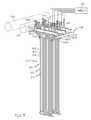
- FIG. 1is a schematic view of a kraft black liquor recovery boiler system constructed in accordance with the present invention
- FIG. 2illustrates a portion of a superheater section of the boiler system of FIG. 1 ; wherein tube structures defining platens are illustrated schematically as rectangular structures;
- FIG. 3illustrates first, second and third tube structures of a platen
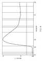
- FIG. 4is an example plot of a tube structure clearing event.
- FIG. 1illustrates a kraft black liquor recovery boiler system 10 constructed in accordance with the present invention.
- Black liquoris a by-product of chemical pulping in a paper-making process.
- the initial concentration of “weak black liquor”is about 15%. It is concentrated to firing conditions (65% to 85% dry solids content) in an evaporator 20 , and then burned in the recovery boiler system 10 .
- the evaporator 20receives the weak black liquor from washers (not shown) downstream from a cooking digester (not shown).
- the boiler system 10comprises a recovery boiler 12 comprising a sealed housing 12 A defining a furnace 30 where a fuel, e.g., black liquor, is burned to generate hot working gases, a heat transfer section 32 and a bullnose 34 in between the furnace 30 and the heat transfer section 32 , see FIG. 1 .
- a fuele.g., black liquor
- hot working gasesmeans the gases generated when fuel is burned in the furnace.
- the boiler system 10further comprises an economizer 40 , a boiler bank 50 and a superheater section 60 , all of which are located in the heat transfer section 32 , see FIG. 1 .
- the hot working gases resulting from the burning of the fuel in the furnace 30pass around the bullnose 34 , travel into and through the heat transfer section 32 , are then filtered through an electrostatic precipitator 70 and exit through a stack 72 , see FIG. 1 .
- another fuel other than black liquorsuch as natural gas or fuel oil
- black liquorinstead of natural gas or fuel oil may be used as the fuel in the furnace 30 .
- Vertically aligned wall tubes 130are incorporated into vertical walls 31 of the furnace 30 .
- a fluidprimarily water, passes through the wall tubes 130 such that energy in the form of heat from the hot working gases generated in the furnace 30 is transferred to the fluid flowing through the wall tubes 130 .
- the furnace 30has primary level air ports 132 , secondary level air ports 134 , and tertiary level air ports 136 for introducing air for combustion at three different height levels.
- Black liquor BLis sprayed into the furnace 30 out of spray guns 138 .
- the black liquor BLis supplied to the guns 138 from the evaporator 20 .
- the injectors 137 and the spray guns 138define fuel supply structure.
- the economizer 40receives feedwater from a supply FS.
- the feedwatermay be supplied to the economizer 40 at a temperature of about 250° F.
- the economizer 40may heat the water to a temperature of about 450° F.
- the hot working gases moving through the heat transfer section 32supply energy in the form of heat to the economizer 40 for heating the feedwater.
- the heated wateris then supplied from the economizer 40 to a top drum (steam drum) 52 of the boiler bank 50 , see FIG. 1 .
- the top drum 52functions generally as a steam-water separator.
- the waterflows down a first set of tubes 54 extending from the top drum 52 to a lower drum (mud drum) 56 .
- the watermay be heated to a temperature of about 400-600° F.
- a portion of the heated waterflows through a second set of tubes 58 in the boiler bank 50 to the upper drum 52 .
- a remaining portion of the heated water in the lower drum 56is supplied to the wall tubes 130 in the furnace 30 .
- the water flowing through the second set of tubes 58 in the boiler bank 50 and the wall tubes 130 in the furnace 30may be heated to a saturated state. In the saturated state, the fluid is mainly a liquid, but some steam may be provided.
- the fluid in the wall tubes 130is returned to the boiler bank 50 at the top drum 52 .
- the steamis separated from the liquid in the top drum 52 .
- the steam in the top drum 52is supplied to the superheater section 60 , while the water returns to the lower drum 56 via the first set of tubes 54 .
- the upper and lower drums 52 , 56may be replaced by a single drum, as is known to those skilled in the art, whereby steam is supplied by the single drum to a superheater section.
- the superheater section 60comprises first, second and third superheaters 62 , 64 and 66 , each of which may comprise between about 20-50 platens 62 A, 64 A and 66 A.
- the platens 62 A, 64 A and 66 Aare suspended from the headers 62 B, 64 B, 66 B, 62 C, 64 C and 66 C, which are themselves suspended from overhead beams (not shown) by hanger rods 200 .
- the hot working gases moving through the heat transfer section 32supply the energy in the form of heat to the superheater section 60 for superheating the steam. It is contemplated that the superheater section 60 may comprise less than three superheaters or more than three superheaters.
- FIG. 3A platen 62 A from the first superheater 62 is illustrated in FIG. 3 .
- the remaining platens 62 A in the first superheater 62 as well as the platens 64 A and 66 A in the second and third superheaters 64 , 66are constructed in generally the same manner.
- the platen 62 Amay comprise first, second and third separate metal tube structures 160 - 162 , see FIG. 3 .
- the platensare schematically illustrated as rectangular structures, but are defined by tube structures.
- the tube structures 160 - 162comprise inlet portions 160 A- 162 A, which communicate with the inlet header 62 B and end portions 160 B- 162 B, which communicate with the outlet header 62 C.
- the tube structure inlet portions 160 A- 162 A and end portions 160 B- 162 Bare located above a roof 12 B of the boiler housing 12 A, see FIGS. 1 and 3 , while intermediate portions 160 C- 162 C of the tube structures 160 - 162 extend within the boiler housing 12 A and are located within the heat transfer section 32 .
- the tube structures 160 - 162define pathways through which fluid, e.g., steam, passes from the inlet header 62 B, though the tube structures 160 - 162 and out the outlet header 62 C. It is contemplated that the platen 62 A may have less than or more than three tube structures, e.g., one, two, four or five tube structures.
- the steamis heated to a superheated state in the superheater section 60 .
- cooled liquid watermay settle in lower bends of the tube structures 160 - 162 in the platens 62 A, 64 A and 66 A.
- the liquid waterprevents steam from passing through the tube structures 160 - 162 .
- the steam moving through the tube structures 160 - 162functions as a cooling fluid for the metal tube structures 160 - 162 .
- the tube structuremay become overheated, especially at an end portion 160 B- 162 B, which may cause damage to the tube structure 160 - 162 .
- start-up of the furnace 30is monitored by a controller 210 to ensure that the furnace 30 is heated slowly until any liquid water in the tube structures 160 - 162 of the superheater section platens 62 A, 64 A and 66 A has safely evaporated before the furnace 30 is heated to an elevated state.
- a temperature measurement device 170which, in the illustrated embodiment, comprises an optical pyrometer, may be provided in or near the heat transfer section 32 to measure the temperature of the hot working gases in the heat transfer section 32 and entering the superheater section 60 .
- the temperature measuring device 170generates a corresponding temperature signal to the controller 210 .
- the temperature sensed by the temperature measurement device 170provides an indication of the amount of energy in the form of heat being generated by the furnace 30 .
- the controller 210has verified that liquid water in the tube structures 160 - 162 has been cleared, the amount of fuel provided by the injectors 137 or the spray guns 138 to the furnace 30 is controlled by the controller 210 at a low level.
- the amount of fuel provided by the injectors 137 or the spray guns 138 to the furnace 30is controlled by the controller 210 such that the temperature of the hot working gases in the heat transfer section 32 and entering the superheater section 60 , as measured by the temperature measuring device 170 , is less than a predefined initial working gas threshold temperature, such as a threshold temperature falling within the range of 800-1000 degrees F., and preferably 900 degrees F. If the temperature of the hot working gases exceeds the threshold temperature, the amount of fuel provided to the furnace 30 is reduced. Once the controller 210 has verified that liquid water in the tube structures 160 has been cleared, then the controller 210 will allow the rate at which fuel is provided to the furnace 30 to increase such that the temperature of the hot working gases entering the superheater section 60 exceeds the threshold temperature.
- a predefined initial working gas threshold temperaturesuch as a threshold temperature falling within the range of 800-1000 degrees F., and preferably 900 degrees F.
- the controller 210comprises any device which receives input data, processes that data through computer instructions, and generates output data.
- a controllercan be a hand-held device, laptop or notebook computer, desktop computer, microcomputer, digital signal processor (DSP), mainframe, server, other programmable computer devices, or any combination thereof.
- DSPdigital signal processor
- the controller 210may also be implemented using programmable logic devices such as field programmable gate arrays (FPGAs) or, alternatively, realized as application specific integrated circuits (ASICs) or similar devices.
- FPGAsfield programmable gate arrays
- ASICsapplication specific integrated circuits
- a temperature sensor 220such as a thermocouple in the illustrated embodiment, is provided at the end portion 160 B- 162 B of the tube structure 160 to measure the temperature of the tube structure 160 - 162 at that location, see FIG. 3 .
- the temperature sensors 220generate corresponding temperature signals to the controller 210 .
- Each tube structure end portion 160 B- 162 Bis located near its corresponding outlet header. It is contemplated that a temperature sensor 220 may not be provided for all of the tube structures 160 - 162 in each of the platens 62 A, 64 A and 66 A. However, it is preferred that a temperature sensor 220 is provided for at least one tube structure 160 - 162 in each platen 62 A, 64 A and 66 A.
- a tube structure clearing eventLiquid water evaporating in a tube structure 160 - 162 after furnace startup is referred to herein as a “tube structure clearing event.”
- a tube structure clearing eventis characterized by rapid changes in temperature at the end portion of the tube structure.
- “rapid changes in temperature” of the end portion 160 B- 162 B of a tube structure 160 - 162are characterized by the temperature increasing monotonically, rapidly, e.g., over a 1-10 minute period, and significantly, e.g., by a temperature increase of at least 25 degrees F., and immediately thereafter, decreasing monotonically, rapidly, e.g., over a 1-15 minute period, by a temperature magnitude decrease equal to or less than the magnitude of the temperature increase but, in any event, the magnitude of the decrease in temperature is greater than zero.
- FIG. 4a plot is illustrated corresponding to a measured tube structure clearing event.
- the temperature of a tube structure end portionbegan to monotonically increase in temperature at about 8075 seconds from about 550 degrees F. to a maximum temperature of about 700 degrees F. at about 8225 seconds.
- the tube structure end portionincreased in temperature by about 150 degrees F.
- the temperature of the tube structure end portionimmediately began to decrease monotonically to a temperature of about 610 degrees F. at about 8725 seconds.
- the tube structure end portionmonotonically decreased in temperature by about 90 degrees.
- the temperature sensors 220are monitored by the controller 210 for rapid temperature changes, i.e., a rapid increased in temperature immediately followed by a rapid decrease in temperature, indicating that fluid is moving through the entire length of their corresponding tube structures 160 - 162 .
- the controller 210may automatically cause (without input from an operator) the injectors 137 or spray guns 138 to increase the amount of fuel provided to the furnace 30 since the temperature of the hot working gases in the heat transfer section 32 and entering the superheater section 60 can safely exceed the predefined initial working gas threshold temperature (800-1000 degrees F. in the illustrated embodiment).
- an “increase in the amount of fuel provided to the furnace”is intended to encompass increasing the rate at which fuel is input into the furnace 30 by either the injectors 137 or the spray guns 138 .
- an increase in the amount of fuel provided to the furnace 30may result when the injectors 137 increase the rate at which natural gas or fuel oil is input into the furnace 30 ; when the injectors 137 stop inputting natural gas or fuel oil while, at that same time, the spray guns 138 begin inputting black liquor into the furnace 30 at a rate which exceeds the rate at which natural gas or fuel oil was injected into the furnace 30 ; or when the spray guns 138 increase the rate at which black liquor is input into the furnace.
- the controller 210may generate a message or otherwise indicate to an operator that a tube structure clearing event has occurred and/or request that the operator input a tube structure clearing verification signal. In an embodiment, the controller 210 will not automatically cause the injectors 137 or spray guns 138 to increase the amount of fuel provided to the furnace 30 once all of the temperature sensors 220 have provided signals to the controller 210 indicating that rapid temperature changes have occurred at their corresponding tube structure end portions, as is done by the embodiment discussed above.
- the controller 210will wait until it receives a verification signal input from the operator, via a keypad, keyboard or other input device, indicating that the operator has verified that a tube structure clearing event has occurred. In this embodiment, only after receiving the verification signal input by the operator will the controller 210 cause the injectors 137 or spray guns 138 to increase the amount of fuel provided to the furnace 30 .
- the controller 210will automatically cause the injectors 137 or spray guns 138 to increase the amount of fuel provided to the furnace 30 once all of the temperature sensors 220 have provided signals to the controller 210 indicating that rapid temperature changes have occurred at their corresponding tube structure end portions, as is done in the embodiment discussed above.
- the controller 210 , temperature measuring device 170 and temperature sensors 220define a monitoring system for the boiler system 10 .
Landscapes
- Engineering & Computer Science (AREA)
- Chemical & Material Sciences (AREA)
- Combustion & Propulsion (AREA)
- Mechanical Engineering (AREA)
- General Engineering & Computer Science (AREA)
- Physics & Mathematics (AREA)
- Thermal Sciences (AREA)
- Control Of Steam Boilers And Waste-Gas Boilers (AREA)
- Control Of Combustion (AREA)
Abstract
Description
Claims (21)
Priority Applications (9)
| Application Number | Priority Date | Filing Date | Title |
|---|---|---|---|
| US14/202,242US9541282B2 (en) | 2014-03-10 | 2014-03-10 | Boiler system controlling fuel to a furnace based on temperature of a structure in a superheater section |
| PCT/US2015/019445WO2015138321A1 (en) | 2014-03-10 | 2015-03-09 | Boiler system controlling fuel to a furnace based on temperature of a structure in a superheater section |
| EP23213552.5AEP4345372A3 (en) | 2014-03-10 | 2015-03-09 | Boiler system controlling fuel to a furnace based on temperature of a structure in a superheater section |
| EP15715881.7AEP3117037B1 (en) | 2014-03-10 | 2015-03-09 | Boiler system controlling fuel to a furnace based on temperature of a structure in a superheater section |
| ES15715881TES2985729T3 (en) | 2014-03-10 | 2015-03-09 | Boiler system that controls the fuel to a furnace based on the temperature of a structure in a superheater section |
| CA2941377ACA2941377C (en) | 2014-03-10 | 2015-03-09 | Boiler system controlling fuel to a furnace based on temperature of a structure in a superheater section |
| PL15715881.7TPL3117037T3 (en) | 2014-03-10 | 2015-03-09 | BOILER SYSTEM CONTROLING FUEL FEEDING TO THE FURNACE BASED ON THE STRUCTURE TEMPERATURE IN THE SUPERHEATER SECTION |
| US15/401,852US20170114995A1 (en) | 2014-03-10 | 2017-01-09 | Boiler system controlling fuel to a furnace based on temperature of a structure in a superheater section |
| US16/568,890US20200003410A1 (en) | 2014-03-10 | 2019-09-12 | Boiler system controlling fuel to a furnace based on temperature of a structure in a superheater section |
Applications Claiming Priority (1)
| Application Number | Priority Date | Filing Date | Title |
|---|---|---|---|
| US14/202,242US9541282B2 (en) | 2014-03-10 | 2014-03-10 | Boiler system controlling fuel to a furnace based on temperature of a structure in a superheater section |
Related Child Applications (1)
| Application Number | Title | Priority Date | Filing Date |
|---|---|---|---|
| US15/401,852ContinuationUS20170114995A1 (en) | 2014-03-10 | 2017-01-09 | Boiler system controlling fuel to a furnace based on temperature of a structure in a superheater section |
Publications (2)
| Publication Number | Publication Date |
|---|---|
| US20150253003A1 US20150253003A1 (en) | 2015-09-10 |
| US9541282B2true US9541282B2 (en) | 2017-01-10 |
Family
ID=52824543
Family Applications (3)
| Application Number | Title | Priority Date | Filing Date |
|---|---|---|---|
| US14/202,242Active2034-11-21US9541282B2 (en) | 2014-03-10 | 2014-03-10 | Boiler system controlling fuel to a furnace based on temperature of a structure in a superheater section |
| US15/401,852AbandonedUS20170114995A1 (en) | 2014-03-10 | 2017-01-09 | Boiler system controlling fuel to a furnace based on temperature of a structure in a superheater section |
| US16/568,890AbandonedUS20200003410A1 (en) | 2014-03-10 | 2019-09-12 | Boiler system controlling fuel to a furnace based on temperature of a structure in a superheater section |
Family Applications After (2)
| Application Number | Title | Priority Date | Filing Date |
|---|---|---|---|
| US15/401,852AbandonedUS20170114995A1 (en) | 2014-03-10 | 2017-01-09 | Boiler system controlling fuel to a furnace based on temperature of a structure in a superheater section |
| US16/568,890AbandonedUS20200003410A1 (en) | 2014-03-10 | 2019-09-12 | Boiler system controlling fuel to a furnace based on temperature of a structure in a superheater section |
Country Status (6)
| Country | Link |
|---|---|
| US (3) | US9541282B2 (en) |
| EP (2) | EP3117037B1 (en) |
| CA (1) | CA2941377C (en) |
| ES (1) | ES2985729T3 (en) |
| PL (1) | PL3117037T3 (en) |
| WO (1) | WO2015138321A1 (en) |
Cited By (1)
| Publication number | Priority date | Publication date | Assignee | Title |
|---|---|---|---|---|
| US12345410B2 (en) | 2020-05-01 | 2025-07-01 | International Paper Company | System and methods for controlling operation of a recovery boiler to reduce fouling |
Families Citing this family (6)
| Publication number | Priority date | Publication date | Assignee | Title |
|---|---|---|---|---|
| US8381690B2 (en) | 2007-12-17 | 2013-02-26 | International Paper Company | Controlling cooling flow in a sootblower based on lance tube temperature |
| US9927231B2 (en)* | 2014-07-25 | 2018-03-27 | Integrated Test & Measurement (ITM), LLC | System and methods for detecting, monitoring, and removing deposits on boiler heat exchanger surfaces using vibrational analysis |
| BR112017001511B1 (en) | 2014-07-25 | 2021-03-02 | International Paper Company | methods, system and computer program product to detect fouling of a boiler heat exchanger |
| US10060688B2 (en) | 2014-07-25 | 2018-08-28 | Integrated Test & Measurement (ITM) | System and methods for detecting, monitoring, and removing deposits on boiler heat exchanger surfaces using vibrational analysis |
| CN109058971B (en)* | 2018-05-04 | 2020-08-14 | 四川通普科技有限公司 | NB-IoT-based boiler operation monitoring system |
| FI129238B (en)* | 2019-09-09 | 2021-10-15 | Valmet Automation Oy | A method for controlling carryover in a chemical recovery boiler and a chemical recovery boiler |
Citations (176)
| Publication number | Priority date | Publication date | Assignee | Title |
|---|---|---|---|---|
| US2416462A (en) | 1942-11-12 | 1947-02-25 | Babcock & Wilcox Co | Method of and apparatus for recovering heat and chemicals |
| US2819702A (en)* | 1951-12-29 | 1958-01-14 | Babcock & Wilcox Co | Method of and apparatus for controlling vapor temperatures |
| US2830440A (en)* | 1951-11-29 | 1958-04-15 | Babcock & Wilcox Co | Method of power generation with divided gas flow over a superheater and a reheater and apparatus therefor |
| US2832323A (en) | 1954-12-07 | 1958-04-29 | Riley Stoker Corp | Superheat control |
| GB802032A (en) | 1955-06-20 | 1958-09-24 | Combustion Eng | A steam generator and method of operating the same |
| US2962006A (en)* | 1958-05-19 | 1960-11-29 | Riley Stoker Corp | Steam generating unit |
| US2966896A (en)* | 1958-03-12 | 1961-01-03 | Sulzer Ag | Method and apparatus for controlling the outlet temperatures of superheaters and reheaters of a steam generating plant |
| US3028844A (en)* | 1952-11-26 | 1962-04-10 | Babcock & Wilcox Co | Control systems |
| US3040719A (en)* | 1952-04-21 | 1962-06-26 | Bailey Meter Co | Vapor generating and superheating systems |
| US3161180A (en)* | 1952-11-26 | 1964-12-15 | Babcock & Wilcox Co | Control systems |
| US3207134A (en)* | 1964-10-22 | 1965-09-21 | Riley Stoker Corp | Steam generating unit |
| GB1022254A (en) | 1962-09-21 | 1966-03-09 | Diamond Power Speciality | Blower type cleaning for heat exchanging apparatus |
| US3246635A (en)* | 1965-04-07 | 1966-04-19 | Combustion Eng | Vapor generator with gas recirculation |
| US3274979A (en)* | 1964-09-28 | 1966-09-27 | Combustion Eng | Soot blower operation for vapor generator furnaces |
| US3291106A (en)* | 1965-09-07 | 1966-12-13 | Combustion Eng | Vapor generator with gas recirculation |
| US3362384A (en)* | 1966-09-08 | 1968-01-09 | Combustion Eng | Steam generation with reheat temperature control |
| US3364903A (en)* | 1966-09-08 | 1968-01-23 | Combustion Eng | Steam generator with reheat temperature regulation |
| US3439376A (en) | 1965-09-09 | 1969-04-22 | Diamond Power Speciality | Long retracting soot blower |
| US3452722A (en)* | 1966-12-30 | 1969-07-01 | Sulzer Ag | Positively operated steam generator |
| US3575002A (en)* | 1965-06-15 | 1971-04-13 | Combustion Eigineering Inc | Combination fossil fuel and superheated steam nuclear power plant |
| GB1376805A (en) | 1972-02-14 | 1974-12-11 | Diamond Power Speciality | Apparatus for detecting gas temperature or heat flow with a soot blower |
| SU464031A1 (en) | 1973-11-05 | 1975-03-15 | Предприятие П/Я Х-5263 | X-ray tube |
| US3955358A (en)* | 1974-08-08 | 1976-05-11 | Westinghouse Electric Corporation | Combined cycle electric power plant and a heat recovery steam generator with improved fluid level control therefor |
| US3965675A (en)* | 1974-08-08 | 1976-06-29 | Westinghouse Electric Corporation | Combined cycle electric power plant and a heat recovery steam generator having improved boiler feed pump flow control |
| US3974644A (en)* | 1974-08-08 | 1976-08-17 | Westinghouse Electric Corporation | Combined cycle electric power plant and heat recovery steam generator having improved multi-loop temperature control of the steam generated |
| US4004647A (en) | 1976-01-30 | 1977-01-25 | The Babcock & Wilcox Company | Load cell arrangement |
| US4028884A (en)* | 1974-12-27 | 1977-06-14 | Westinghouse Electric Corporation | Control apparatus for controlling the operation of a gas turbine inlet guide vane assembly and heat recovery steam generator for a steam turbine employed in a combined cycle electric power generating plant |
| US4031404A (en)* | 1974-08-08 | 1977-06-21 | Westinghouse Electric Corporation | Combined cycle electric power plant and a heat recovery steam generator having improved temperature control of the steam generated |
| US4037469A (en) | 1975-08-11 | 1977-07-26 | Transrail Ab | Force measuring apparatus |
| US4085438A (en) | 1976-11-11 | 1978-04-18 | Copes-Vulcan Inc. | Digital sootblower control systems and methods therefor |
| US4099384A (en) | 1975-01-02 | 1978-07-11 | Foster Wheeler Energy Corporation | Integral separator start-up system for a vapor generator with constant pressure furnace circuitry |
| US4237825A (en)* | 1978-11-06 | 1980-12-09 | Combustion Engineering, Inc. | Furnace heat absorption control |
| US4339998A (en) | 1980-04-25 | 1982-07-20 | James Finch | Fuel level indicator |
| US4351277A (en) | 1981-01-23 | 1982-09-28 | Tranter, Inc. | Sootblower for economizer |
| US4359800A (en) | 1981-03-05 | 1982-11-23 | The Babcock & Wilcox Company | Sootblower feed and lance tube structure with improved turbulizer system |
| US4375710A (en) | 1981-09-10 | 1983-03-08 | The Babcock & Wilcox Company | Roller supporting means for long retracting sootblowers |
| US4377134A (en)* | 1981-08-03 | 1983-03-22 | Combustion Engineering, Inc. | Steam temperature control with overfire air firing |
| US4380843A (en) | 1980-12-08 | 1983-04-26 | Combustion Engineering, Inc. | Droop correction structure and condensate control in sootblowers |
| US4411204A (en)* | 1981-12-07 | 1983-10-25 | Combustion Engineering, Inc. | Method of firing a pulverized fuel-fired steam generator |
| US4421067A (en) | 1982-09-07 | 1983-12-20 | Deltak Corporation | Apparatus and method for soot cleaning in high-pressure heat exchangers |
| US4422882A (en) | 1981-12-29 | 1983-12-27 | The Babcock & Wilcox Company | Pulsed liquid jet-type cleaning of highly heated surfaces |
| US4430963A (en) | 1982-12-03 | 1984-02-14 | General Signal | System for generating dry coal weight signal for coal feeder and control system based thereon |
| US4454840A (en) | 1983-07-14 | 1984-06-19 | The Babcock & Wilcox Company | Enhanced sootblowing system |
| US4466383A (en) | 1983-10-12 | 1984-08-21 | The Babcock & Wilcox Company | Boiler cleaning optimization with fouling rate identification |
| US4475482A (en) | 1982-08-06 | 1984-10-09 | The Babcock & Wilcox Company | Sootblowing optimization |
| US4488516A (en) | 1983-11-18 | 1984-12-18 | Combustion Engineering, Inc. | Soot blower system |
| US4492187A (en) | 1983-12-05 | 1985-01-08 | The Babcock & Wilcox Company | Sootblower apparatus |
| US4539840A (en) | 1983-11-14 | 1985-09-10 | The Babcock & Wilcox Company | Sootblowing system with identification of model parameters |
| US4565324A (en) | 1983-06-01 | 1986-01-21 | The Babcock & Wilcox Company | Nozzle structure for sootblower |
| US4567622A (en) | 1984-03-16 | 1986-02-04 | The Babcock & Wilcox Company | Sootblower nozzle apparatus |
| US4599975A (en) | 1983-09-01 | 1986-07-15 | 471199 Ontario Limited | Control of boiler operations |
| US4621583A (en) | 1985-06-28 | 1986-11-11 | Measurex Corporation | System for controlling a bark-fired boiler |
| JPS62278217A (en) | 1986-05-27 | 1987-12-03 | Nippon Steel Corp | Lance inlaying thermocouple for controlling slag level |
| US4716856A (en)* | 1985-06-12 | 1988-01-05 | Metallgesellschaft Ag | Integral fluidized bed heat exchanger in an energy producing plant |
| US4718363A (en) | 1985-02-28 | 1988-01-12 | Williames Hi-Tech Int'l Pty Ltd. | Multi-purpose seeding machine |
| US4718376A (en) | 1985-11-01 | 1988-01-12 | Weyerhaeuser Company | Boiler sootblowing control system |
| USRE32723E (en) | 1983-11-23 | 1988-08-02 | Neundorfer, Inc. | Apparatus for deslagging steam generator tubes |
| US4779690A (en) | 1987-09-15 | 1988-10-25 | Racal-Chubb Canada Limited | System for weighing containers |
| US4803959A (en) | 1988-03-24 | 1989-02-14 | The Babcock & Wilcox Company | Indexing sootblower |
| US4887431A (en)* | 1989-04-05 | 1989-12-19 | The Babcock & Wilcox Company | Superheater outlet steam temperature control |
| US4920994A (en) | 1989-09-12 | 1990-05-01 | The United States Of America As Represented By The United States Department Of Energy | Laser removal of sludge from steam generators |
| US4957049A (en)* | 1990-02-22 | 1990-09-18 | Electrodyne Research Corp. | Organic waste fuel combustion system integrated with a gas turbine combined cycle |
| US4980674A (en) | 1989-11-27 | 1990-12-25 | Electric Power Research Institute, Inc. | Acoustic ash deposition monitor apparatus and method |
| US4986391A (en) | 1989-11-30 | 1991-01-22 | Otis Elevator Company | Elevator load weighing |
| US4996951A (en) | 1990-02-07 | 1991-03-05 | Westinghouse Electric Corp. | Method for soot blowing automation/optimization in boiler operation |
| US5027751A (en) | 1990-07-02 | 1991-07-02 | Westinghouse Electric Corp. | Method and apparatus for optimized boiler operation |
| US5050108A (en)* | 1989-11-30 | 1991-09-17 | Aptech Engineering, Inc. | Method for extending the useful life of boiler tubes |
| US5048636A (en) | 1990-02-07 | 1991-09-17 | Harness, Dickey & Pierce | Low noise wallbox for sootblower |
| US5063632A (en) | 1990-12-04 | 1991-11-12 | The Babcock & Wilcox Company | Sootblower with condensate separator |
| US5065472A (en) | 1991-01-24 | 1991-11-19 | The Babcock & Wilcox Co. | Spring loaded brake assembly for indexing sootblower |
| US5090087A (en) | 1991-04-12 | 1992-02-25 | The Babcock & Wilcox Company | Hub assembly for sootblower |
| US5113802A (en) | 1991-03-26 | 1992-05-19 | Union Camp Corporation | Method and apparatus for removing deposit from recovery boilers |
| US5181482A (en) | 1991-12-13 | 1993-01-26 | Stone & Webster Engineering Corp. | Sootblowing advisor and automation system |
| WO1993005338A1 (en) | 1991-08-29 | 1993-03-18 | John Botham | Method of monitoring a load and apparatus for use in the method |
| US5209324A (en) | 1991-06-03 | 1993-05-11 | Safematic Oy | Method for controlling a sootblower lubrication system |
| US5230306A (en) | 1991-07-25 | 1993-07-27 | The Babcock & Wilcox Company | Ceramic sootblower element |
| US5237718A (en) | 1992-05-01 | 1993-08-24 | The Babcock & Wilcox Company | Sootblower with lance bypass flow |
| US5241723A (en) | 1991-10-21 | 1993-09-07 | The Babcock & Wilcox Company | Nozzle structure with improved stream coherence |
| US5261965A (en) | 1992-08-28 | 1993-11-16 | Texas Instruments Incorporated | Semiconductor wafer cleaning using condensed-phase processing |
| US5267533A (en) | 1992-07-20 | 1993-12-07 | The Babcock & Wilcox Company | Self-adjusting packing gland for sootblower |
| US5271356A (en) | 1992-10-01 | 1993-12-21 | The Babcock And Wilcox Company | Low profile sootblower nozzle |
| US5286063A (en) | 1993-01-08 | 1994-02-15 | The Babcock & Wilcox Company | Ball and socket floating seal assembly |
| US5299533A (en) | 1993-03-22 | 1994-04-05 | The Babcock & Wilcox Company | Open beam sootblower |
| GB2271440A (en) | 1992-10-03 | 1994-04-13 | Boiler Management Systems Limi | Optimising boiler cleaning |
| US5305713A (en) | 1992-07-29 | 1994-04-26 | Vadakin, Inc. | Angular rotation rotary cleaning device |
| US5320073A (en) | 1993-02-03 | 1994-06-14 | The Babcock And Wilcox Company | Method and apparatus of preheating a sootblower lance |
| US5348774A (en) | 1993-08-11 | 1994-09-20 | Alliedsignal Inc. | Method of rapidly densifying a porous structure |
| US5353996A (en) | 1993-02-18 | 1994-10-11 | Boise Cascade Corporation | Sootblower frame and drive assembly |
| US5375771A (en) | 1993-02-10 | 1994-12-27 | Jameel; Mohomed I. | Advanced sootblower nozzle design |
| US5398623A (en) | 1992-05-13 | 1995-03-21 | Noell Abfall- Und Energietechnik Gmbh | Method for incinerating refuse, and a control process therefor |
| US5416946A (en) | 1992-05-01 | 1995-05-23 | The Babcock & Wilcox Company | Sootblower having variable discharge |
| US5423483A (en) | 1993-11-12 | 1995-06-13 | Schwade; Hans H. | Sootblower |
| US5423272A (en)* | 1994-04-11 | 1995-06-13 | Combustion Engineering, Inc. | Method for optimizing the operating efficiency of a fossil fuel-fired power generation system |
| US5429076A (en) | 1993-03-22 | 1995-07-04 | The Babcock & Wilcox Company | Open beam sootblower |
| US5477683A (en) | 1991-12-20 | 1995-12-26 | Abb Carbon Ab | Method and device during starting and low-load operation of a once-through boiler |
| US5505163A (en) | 1994-03-18 | 1996-04-09 | Jameel; Mohomed I. | Sootblower nozzle |
| US5509607A (en) | 1994-06-30 | 1996-04-23 | The Babcock & Wilcox Company | Convertible media sootblower lance tube |
| US5522348A (en)* | 1991-09-02 | 1996-06-04 | Nippon Furnace Kogyo Kabushiki Kaisha | Boiler |
| US5530987A (en) | 1992-07-24 | 1996-07-02 | The Babcock & Wilcox Company | Condensate drain controller |
| US5549305A (en) | 1995-04-07 | 1996-08-27 | Freund; Melvin A. | Sootblower packing gland |
| US5605117A (en) | 1994-11-21 | 1997-02-25 | The Babcock & Wilcox Company | Articulating sootblower |
| US5606924A (en) | 1993-12-29 | 1997-03-04 | Martin Gmbh Fuer Umwelt- Und Energietechnik | Process for regulating individual factors or all factors influencing combustion on a furnace grate |
| US5615734A (en) | 1994-11-16 | 1997-04-01 | Westinghouse Electric Corporation | Sludge lance inspection and verification system |
| US5619771A (en) | 1995-08-11 | 1997-04-15 | Effox, Inc. | Oscillating and reverse cleaning sootblower |
| US5626184A (en) | 1995-08-24 | 1997-05-06 | Abb Air Preheater, Inc. | Sootblower |
| US5663489A (en) | 1994-11-14 | 1997-09-02 | Betzdearborn Inc. | Methods and apparatus for monitoring water process equipment |
| US5675863A (en) | 1995-08-28 | 1997-10-14 | Combustion Engineering, Inc. | Full coverage sootblower |
| US5740745A (en) | 1996-09-20 | 1998-04-21 | Nalco Fuel Tech | Process for increasing the effectiveness of slag control chemicals for black liquor recovery and other combustion units |
| US5756880A (en) | 1997-02-13 | 1998-05-26 | Betzdearborn Inc. | Methods and apparatus for monitoring water process equipment |
| US5765510A (en) | 1996-04-26 | 1998-06-16 | Dltk, Inc. | Retractable, sealed sootblower for high pressure, high temperature applications |
| US5769035A (en) | 1996-10-24 | 1998-06-23 | Mcdermott Technology, Inc. | Boiler furnace puff sootblower |
| US5769034A (en) | 1997-01-17 | 1998-06-23 | Zilka; Frank | Device, system and method for on-line explosive deslagging |
| WO1998027384A1 (en) | 1996-12-19 | 1998-06-25 | Kvaerner Pulping Oy | Method in a boiler, particularly a chemical recovery boiler |
| US5778830A (en) | 1997-01-02 | 1998-07-14 | Combustion Engineering, Inc. | Closed frame sootblower with top access |
| US5778831A (en) | 1994-03-18 | 1998-07-14 | Bergemann Usa, Inc. | Sootblower lance with expanded tip |
| US5793014A (en) | 1995-12-27 | 1998-08-11 | Electricite De France - Service National | Process and device for restoring the tightness of connecting elements such as water boxes of alternators with a mixed water-hydrogen cooling system |
| JPH10274408A (en) | 1997-01-30 | 1998-10-13 | Sumitomo Metal Ind Ltd | Soot blower operation method for waste heat recovery boiler |
| US5836268A (en) | 1997-01-02 | 1998-11-17 | Combustion Engineering, Inc. | Sootblower with travelling limit switch |
| EP0905308A1 (en) | 1997-09-26 | 1999-03-31 | L'air Liquide, Societe Anonyme Pour L'etude Et L'exploitation Des Procedes Georges Claude | Methods of improving productivity of black liquor recovery boilers |
| US5920951A (en) | 1997-04-03 | 1999-07-13 | Diamond Power International, Inc. | Parameter sensing sootblower |
| US5943865A (en)* | 1998-12-03 | 1999-08-31 | Cohen; Mitchell B. | Reheating flue gas for selective catalytic systems |
| US5983639A (en) | 1995-03-02 | 1999-11-16 | Siemens Aktiengesellschaft | Method and system for starting up a continuous flow steam generator |
| RU2143087C1 (en) | 1997-04-24 | 1999-12-20 | Мартин ГмбХ Фюр Умвельт-Унд Энергитехник | Method of removal of deposits from inner and outer surfaces of supply nozzles or supply pipes of furnace units (versions) and device for realization of this method |
| US6065528A (en) | 1999-08-09 | 2000-05-23 | Abb Air Preheater, Inc. | Air preheater cleaner |
| US6073641A (en) | 1995-05-30 | 2000-06-13 | Bude; Friedrich | Drive system for a water lance blower with a housing for blocking and flushing medium and a method for its operation |
| US6109096A (en) | 1997-02-13 | 2000-08-29 | Betzdearborn Inc. | Methods and apparatus for monitoring water process equipment |
| EP1063021A1 (en) | 1999-06-21 | 2000-12-27 | Frigomat S.p.a. | Cleaning apparatus for plants of delivery of liquid or pasty foodstuff products |
| US6170117B1 (en) | 1999-11-15 | 2001-01-09 | Abb Air Preheater, Inc. | Multiple rake sootblower with internal valving manifold |
| US6244098B1 (en) | 1997-02-13 | 2001-06-12 | Betzdearborn Inc. | Methods and apparatus for monitoring water process equipment |
| US6321690B1 (en) | 1997-01-17 | 2001-11-27 | North American Industrial Services, Inc. | Device, system and method for on-line explosive deslagging |
| US6323442B1 (en) | 1999-12-07 | 2001-11-27 | International Paper Company | System and method for measuring weight of deposit on boiler superheaters |
| US6325025B1 (en) | 1999-11-09 | 2001-12-04 | Applied Synergistics, Inc. | Sootblowing optimization system |
| US6431073B1 (en) | 1998-01-14 | 2002-08-13 | North American Industrial Services, Inc. | Device, system and method for on-line explosive deslagging |
| US6437285B1 (en) | 1998-06-02 | 2002-08-20 | General Lasertronics Corporation | Method and apparatus for treating interior cylindrical surfaces and ablating surface material thereon |
| JP2003156211A (en) | 2001-11-19 | 2003-05-30 | Babcock Hitachi Kk | Soot blower device |
| US6575122B2 (en) | 2001-07-20 | 2003-06-10 | Diamond Power International, Inc. | Oscillating sootblower mechanism |
| US6581549B2 (en) | 2000-08-31 | 2003-06-24 | Clyde Bergemann, Inc. | Sootblower lance port with leak resistant cardon joint |
| WO2003104547A1 (en) | 2002-06-07 | 2003-12-18 | Andritz Oy | System for producing energy at a pulp mill |
| US20040006841A1 (en) | 2002-07-09 | 2004-01-15 | Jameel Mohomed Ishag | Multi-media rotating sootblower and automatic industrial boiler cleaning system |
| US6710285B2 (en) | 2002-06-01 | 2004-03-23 | First Call Explosive Solutions, Inc. | Laser system for slag removal |
| US6715499B2 (en) | 2000-03-01 | 2004-04-06 | Clyde Bergmann Gmbh | Water lance blower with monitoring device for quality of a water jet and method of operating the same |
| US6725911B2 (en) | 2001-09-28 | 2004-04-27 | Gas Research Institute | Corrosion resistance treatment of condensing heat exchanger steel structures exposed to a combustion environment |
| US6736089B1 (en) | 2003-06-05 | 2004-05-18 | Neuco, Inc. | Method and system for sootblowing optimization |
| US6755156B1 (en) | 1999-09-13 | 2004-06-29 | Northamerican Industrial Services, Inc. | Device, system and method for on-line explosive deslagging |
| US6764030B2 (en) | 2001-01-12 | 2004-07-20 | Diamond Power International, Inc. | Sootblower nozzle assembly with an improved downstream nozzle |
| US6772775B2 (en) | 2000-12-22 | 2004-08-10 | Diamond Power International, Inc. | Sootblower mechanism providing varying lance rotational speed |
| US6782902B2 (en) | 2000-01-12 | 2004-08-31 | Diamond Power International, Inc. | Sootblower lance tube for dual cleaning media |
| US20040226758A1 (en) | 2003-05-14 | 2004-11-18 | Andrew Jones | System and method for measuring weight of deposit on boiler superheaters |
| US20050199743A1 (en) | 2004-03-15 | 2005-09-15 | Hochstein James R.Jr. | Control of detonative cleaning apparatus |
| US6964709B2 (en) | 2000-01-14 | 2005-11-15 | Babcock-Hitachi Kabushiki Kaisha | Acoustic soot blower, and method for operating the same |
| US7017500B2 (en) | 2004-03-30 | 2006-03-28 | International Paper Company | Monitoring of fuel on a grate fired boiler |
| US20060065291A1 (en) | 2004-09-27 | 2006-03-30 | International Paper Company | Method of determining individual sootblower effectiveness |
| US7028926B2 (en) | 2001-01-12 | 2006-04-18 | Diamond Power International, Inc. | Sootblower nozzle assembly with nozzles having different geometries |
| US7055209B2 (en) | 2003-04-04 | 2006-06-06 | Jss Power Solutions, Llc | Method and apparatus for converting a sootblower from a single motor to a dual motor drive |
| US20060236696A1 (en) | 2005-04-22 | 2006-10-26 | Andritz Oy | Apparatus and method for producing energy at a pulp mill |
| WO2007028447A1 (en) | 2005-07-29 | 2007-03-15 | Clyde Bergemann Gmbh | Selective cleaning of heat exchanger devices in the boiler of a combustion plant |
| US7204208B2 (en) | 2003-06-17 | 2007-04-17 | S.A. Robotics | Method and apparatuses to remove slag |
| WO2008057039A1 (en) | 2006-11-06 | 2008-05-15 | Soottech Aktiebolag | A method of rebuilding a sootblowing system of a recovery furnace, a sootblower for a recovery furnace, and a sootblowing system including a plurality of sootblowers |
| US20090090311A1 (en) | 2007-10-05 | 2009-04-09 | Neuco, Inc. | Sootblowing optimization for improved boiler performance |
| US20090151656A1 (en) | 2007-12-17 | 2009-06-18 | Jones Andrew K | Controlling cooling flow in a sootblower based on lance tube temperature |
| US7584024B2 (en) | 2005-02-08 | 2009-09-01 | Pegasus Technologies, Inc. | Method and apparatus for optimizing operation of a power generating plant using artificial intelligence techniques |
| WO2009139714A1 (en) | 2008-05-13 | 2009-11-19 | Soottech Aktiebolag | A method for measuring conditions in a power boiler furnace using a sootblower |
| US7633033B2 (en) | 2004-01-09 | 2009-12-15 | General Lasertronics Corporation | Color sensing for laser decoating |
| GB2428312B (en) | 2005-06-06 | 2009-12-30 | Emerson Process Management | Method and apparatus for controlling soot blowing using statistical process control |
| US20100077946A1 (en)* | 2008-09-26 | 2010-04-01 | Air Products And Chemicals, Inc. | Process temperature control in oxy/fuel combustion system |
| US20100101462A1 (en)* | 2008-10-27 | 2010-04-29 | Hitachi, Ltd. | Oxyfuel Boiler and a Method of Controlling the Same |
| US7735435B2 (en) | 2006-05-24 | 2010-06-15 | Diamond Power International, Inc. | Apparatus for cleaning a smelt spout of a combustion device |
| US20100199930A1 (en) | 2009-02-06 | 2010-08-12 | Clyde Bergemann, Inc. | Sootblower having a nozzle with deep reaching jets and edge cleaning jets |
| WO2010098946A2 (en) | 2009-02-24 | 2010-09-02 | Adams Terry N | Systems and methods for controlling the operation of sootblowers |
| US20110011315A1 (en)* | 2009-07-14 | 2011-01-20 | Hitachi, Ltd. | Oxyfuel Boiler and Control Method for Oxyfuel Boiler |
| US20120270162A1 (en)* | 2009-09-21 | 2012-10-25 | Kailash & Stefan Pty Ltd | Combustion control system |
| WO2014068325A1 (en) | 2012-11-02 | 2014-05-08 | Epsco Limited | Method and apparatus for inspection of cooling towers |
| US20140150825A1 (en)* | 2011-04-21 | 2014-06-05 | Clyde Bergemann Gmbh Maschinen-Und Apparatebau | Cleaning device for a thermal power plant, method for installing a cleaning device and method for cleaning a thermal power plant |
| EP2784477A1 (en) | 2013-03-28 | 2014-10-01 | Universität Stuttgart | Method and apparatus for determining deposits in power plant boilers and high-temperature furnaces |
| US9091182B2 (en)* | 2010-12-20 | 2015-07-28 | Invensys Systems, Inc. | Feedwater heater control system for improved rankine cycle power plant efficiency |
| US20160025600A1 (en) | 2014-07-25 | 2016-01-28 | Integrated Test & Measurement | System and method for determining a location of fouling on boiler heat transfer surface |
Family Cites Families (3)
| Publication number | Priority date | Publication date | Assignee | Title |
|---|---|---|---|---|
| US4776301A (en)* | 1987-03-12 | 1988-10-11 | The Babcock & Wilcox Company | Advanced steam temperature control |
| DE19504308C1 (en)* | 1995-02-09 | 1996-08-08 | Siemens Ag | Method and device for starting a once-through steam generator |
| DE102008009129A1 (en)* | 2008-02-14 | 2009-08-20 | Hitachi Power Europe Gmbh | Coal-fired power plant and method of operation of the coal-fired power plant |
- 2014
- 2014-03-10USUS14/202,242patent/US9541282B2/enactiveActive
- 2015
- 2015-03-09EPEP15715881.7Apatent/EP3117037B1/enactiveActive
- 2015-03-09PLPL15715881.7Tpatent/PL3117037T3/enunknown
- 2015-03-09WOPCT/US2015/019445patent/WO2015138321A1/enactiveApplication Filing
- 2015-03-09CACA2941377Apatent/CA2941377C/enactiveActive
- 2015-03-09EPEP23213552.5Apatent/EP4345372A3/enactivePending
- 2015-03-09ESES15715881Tpatent/ES2985729T3/enactiveActive
- 2017
- 2017-01-09USUS15/401,852patent/US20170114995A1/ennot_activeAbandoned
- 2019
- 2019-09-12USUS16/568,890patent/US20200003410A1/ennot_activeAbandoned
Patent Citations (202)
| Publication number | Priority date | Publication date | Assignee | Title |
|---|---|---|---|---|
| US2416462A (en) | 1942-11-12 | 1947-02-25 | Babcock & Wilcox Co | Method of and apparatus for recovering heat and chemicals |
| US2830440A (en)* | 1951-11-29 | 1958-04-15 | Babcock & Wilcox Co | Method of power generation with divided gas flow over a superheater and a reheater and apparatus therefor |
| US2819702A (en)* | 1951-12-29 | 1958-01-14 | Babcock & Wilcox Co | Method of and apparatus for controlling vapor temperatures |
| US3040719A (en)* | 1952-04-21 | 1962-06-26 | Bailey Meter Co | Vapor generating and superheating systems |
| US3028844A (en)* | 1952-11-26 | 1962-04-10 | Babcock & Wilcox Co | Control systems |
| US3161180A (en)* | 1952-11-26 | 1964-12-15 | Babcock & Wilcox Co | Control systems |
| US2832323A (en) | 1954-12-07 | 1958-04-29 | Riley Stoker Corp | Superheat control |
| GB802032A (en) | 1955-06-20 | 1958-09-24 | Combustion Eng | A steam generator and method of operating the same |
| US2966896A (en)* | 1958-03-12 | 1961-01-03 | Sulzer Ag | Method and apparatus for controlling the outlet temperatures of superheaters and reheaters of a steam generating plant |
| US2962006A (en)* | 1958-05-19 | 1960-11-29 | Riley Stoker Corp | Steam generating unit |
| GB1022254A (en) | 1962-09-21 | 1966-03-09 | Diamond Power Speciality | Blower type cleaning for heat exchanging apparatus |
| US3274979A (en)* | 1964-09-28 | 1966-09-27 | Combustion Eng | Soot blower operation for vapor generator furnaces |
| US3207134A (en)* | 1964-10-22 | 1965-09-21 | Riley Stoker Corp | Steam generating unit |
| US3246635A (en)* | 1965-04-07 | 1966-04-19 | Combustion Eng | Vapor generator with gas recirculation |
| US3575002A (en)* | 1965-06-15 | 1971-04-13 | Combustion Eigineering Inc | Combination fossil fuel and superheated steam nuclear power plant |
| US3291106A (en)* | 1965-09-07 | 1966-12-13 | Combustion Eng | Vapor generator with gas recirculation |
| US3439376A (en) | 1965-09-09 | 1969-04-22 | Diamond Power Speciality | Long retracting soot blower |
| US3362384A (en)* | 1966-09-08 | 1968-01-09 | Combustion Eng | Steam generation with reheat temperature control |
| US3364903A (en)* | 1966-09-08 | 1968-01-23 | Combustion Eng | Steam generator with reheat temperature regulation |
| US3452722A (en)* | 1966-12-30 | 1969-07-01 | Sulzer Ag | Positively operated steam generator |
| GB1376805A (en) | 1972-02-14 | 1974-12-11 | Diamond Power Speciality | Apparatus for detecting gas temperature or heat flow with a soot blower |
| SU464031A1 (en) | 1973-11-05 | 1975-03-15 | Предприятие П/Я Х-5263 | X-ray tube |
| US3955358A (en)* | 1974-08-08 | 1976-05-11 | Westinghouse Electric Corporation | Combined cycle electric power plant and a heat recovery steam generator with improved fluid level control therefor |
| US3965675A (en)* | 1974-08-08 | 1976-06-29 | Westinghouse Electric Corporation | Combined cycle electric power plant and a heat recovery steam generator having improved boiler feed pump flow control |
| US3974644A (en)* | 1974-08-08 | 1976-08-17 | Westinghouse Electric Corporation | Combined cycle electric power plant and heat recovery steam generator having improved multi-loop temperature control of the steam generated |
| US4031404A (en)* | 1974-08-08 | 1977-06-21 | Westinghouse Electric Corporation | Combined cycle electric power plant and a heat recovery steam generator having improved temperature control of the steam generated |
| US4028884A (en)* | 1974-12-27 | 1977-06-14 | Westinghouse Electric Corporation | Control apparatus for controlling the operation of a gas turbine inlet guide vane assembly and heat recovery steam generator for a steam turbine employed in a combined cycle electric power generating plant |
| US4099384A (en) | 1975-01-02 | 1978-07-11 | Foster Wheeler Energy Corporation | Integral separator start-up system for a vapor generator with constant pressure furnace circuitry |
| US4037469A (en) | 1975-08-11 | 1977-07-26 | Transrail Ab | Force measuring apparatus |
| US4004647A (en) | 1976-01-30 | 1977-01-25 | The Babcock & Wilcox Company | Load cell arrangement |
| US4085438A (en) | 1976-11-11 | 1978-04-18 | Copes-Vulcan Inc. | Digital sootblower control systems and methods therefor |
| US4237825A (en)* | 1978-11-06 | 1980-12-09 | Combustion Engineering, Inc. | Furnace heat absorption control |
| US4339998A (en) | 1980-04-25 | 1982-07-20 | James Finch | Fuel level indicator |
| US4380843A (en) | 1980-12-08 | 1983-04-26 | Combustion Engineering, Inc. | Droop correction structure and condensate control in sootblowers |
| US4351277A (en) | 1981-01-23 | 1982-09-28 | Tranter, Inc. | Sootblower for economizer |
| US4359800A (en) | 1981-03-05 | 1982-11-23 | The Babcock & Wilcox Company | Sootblower feed and lance tube structure with improved turbulizer system |
| SU1291031A3 (en) | 1981-03-05 | 1987-02-15 | Дзе Бабкок Энд Вилкокс Компани (Фирма) | Movable device for removing soot |
| EP0071815B1 (en) | 1981-08-03 | 1986-09-24 | Combustion Engineering, Inc. | Steam temperature control with overfire air firing |
| US4377134A (en)* | 1981-08-03 | 1983-03-22 | Combustion Engineering, Inc. | Steam temperature control with overfire air firing |
| US4375710A (en) | 1981-09-10 | 1983-03-08 | The Babcock & Wilcox Company | Roller supporting means for long retracting sootblowers |
| US4411204A (en)* | 1981-12-07 | 1983-10-25 | Combustion Engineering, Inc. | Method of firing a pulverized fuel-fired steam generator |
| US4422882A (en) | 1981-12-29 | 1983-12-27 | The Babcock & Wilcox Company | Pulsed liquid jet-type cleaning of highly heated surfaces |
| US4475482A (en) | 1982-08-06 | 1984-10-09 | The Babcock & Wilcox Company | Sootblowing optimization |
| US4421067A (en) | 1982-09-07 | 1983-12-20 | Deltak Corporation | Apparatus and method for soot cleaning in high-pressure heat exchangers |
| US4430963A (en) | 1982-12-03 | 1984-02-14 | General Signal | System for generating dry coal weight signal for coal feeder and control system based thereon |
| US4565324A (en) | 1983-06-01 | 1986-01-21 | The Babcock & Wilcox Company | Nozzle structure for sootblower |
| US4454840A (en) | 1983-07-14 | 1984-06-19 | The Babcock & Wilcox Company | Enhanced sootblowing system |
| US4599975A (en) | 1983-09-01 | 1986-07-15 | 471199 Ontario Limited | Control of boiler operations |
| US4466383A (en) | 1983-10-12 | 1984-08-21 | The Babcock & Wilcox Company | Boiler cleaning optimization with fouling rate identification |
| US4539840A (en) | 1983-11-14 | 1985-09-10 | The Babcock & Wilcox Company | Sootblowing system with identification of model parameters |
| US4488516A (en) | 1983-11-18 | 1984-12-18 | Combustion Engineering, Inc. | Soot blower system |
| USRE32723E (en) | 1983-11-23 | 1988-08-02 | Neundorfer, Inc. | Apparatus for deslagging steam generator tubes |
| US4492187A (en) | 1983-12-05 | 1985-01-08 | The Babcock & Wilcox Company | Sootblower apparatus |
| US4567622A (en) | 1984-03-16 | 1986-02-04 | The Babcock & Wilcox Company | Sootblower nozzle apparatus |
| US4718363A (en) | 1985-02-28 | 1988-01-12 | Williames Hi-Tech Int'l Pty Ltd. | Multi-purpose seeding machine |
| US4716856A (en)* | 1985-06-12 | 1988-01-05 | Metallgesellschaft Ag | Integral fluidized bed heat exchanger in an energy producing plant |
| US4621583A (en) | 1985-06-28 | 1986-11-11 | Measurex Corporation | System for controlling a bark-fired boiler |
| US4718376A (en) | 1985-11-01 | 1988-01-12 | Weyerhaeuser Company | Boiler sootblowing control system |
| JPS62278217A (en) | 1986-05-27 | 1987-12-03 | Nippon Steel Corp | Lance inlaying thermocouple for controlling slag level |
| US4779690A (en) | 1987-09-15 | 1988-10-25 | Racal-Chubb Canada Limited | System for weighing containers |
| US4803959A (en) | 1988-03-24 | 1989-02-14 | The Babcock & Wilcox Company | Indexing sootblower |
| US4887431A (en)* | 1989-04-05 | 1989-12-19 | The Babcock & Wilcox Company | Superheater outlet steam temperature control |
| US4920994A (en) | 1989-09-12 | 1990-05-01 | The United States Of America As Represented By The United States Department Of Energy | Laser removal of sludge from steam generators |
| US4980674A (en) | 1989-11-27 | 1990-12-25 | Electric Power Research Institute, Inc. | Acoustic ash deposition monitor apparatus and method |
| US4986391A (en) | 1989-11-30 | 1991-01-22 | Otis Elevator Company | Elevator load weighing |
| US5050108A (en)* | 1989-11-30 | 1991-09-17 | Aptech Engineering, Inc. | Method for extending the useful life of boiler tubes |
| US4996951A (en) | 1990-02-07 | 1991-03-05 | Westinghouse Electric Corp. | Method for soot blowing automation/optimization in boiler operation |
| US5048636A (en) | 1990-02-07 | 1991-09-17 | Harness, Dickey & Pierce | Low noise wallbox for sootblower |
| US4957049A (en)* | 1990-02-22 | 1990-09-18 | Electrodyne Research Corp. | Organic waste fuel combustion system integrated with a gas turbine combined cycle |
| US5027751A (en) | 1990-07-02 | 1991-07-02 | Westinghouse Electric Corp. | Method and apparatus for optimized boiler operation |
| US5063632A (en) | 1990-12-04 | 1991-11-12 | The Babcock & Wilcox Company | Sootblower with condensate separator |
| US5065472A (en) | 1991-01-24 | 1991-11-19 | The Babcock & Wilcox Co. | Spring loaded brake assembly for indexing sootblower |
| US5113802A (en) | 1991-03-26 | 1992-05-19 | Union Camp Corporation | Method and apparatus for removing deposit from recovery boilers |
| US5090087A (en) | 1991-04-12 | 1992-02-25 | The Babcock & Wilcox Company | Hub assembly for sootblower |
| US5209324A (en) | 1991-06-03 | 1993-05-11 | Safematic Oy | Method for controlling a sootblower lubrication system |
| US5230306A (en) | 1991-07-25 | 1993-07-27 | The Babcock & Wilcox Company | Ceramic sootblower element |
| WO1993005338A1 (en) | 1991-08-29 | 1993-03-18 | John Botham | Method of monitoring a load and apparatus for use in the method |
| EP0602244B1 (en) | 1991-09-02 | 1999-01-07 | Nippon Furnace Kogyo Kabushiki Kaisha | Boiler |
| US5522348A (en)* | 1991-09-02 | 1996-06-04 | Nippon Furnace Kogyo Kabushiki Kaisha | Boiler |
| US5241723A (en) | 1991-10-21 | 1993-09-07 | The Babcock & Wilcox Company | Nozzle structure with improved stream coherence |
| US5181482A (en) | 1991-12-13 | 1993-01-26 | Stone & Webster Engineering Corp. | Sootblowing advisor and automation system |
| US5477683A (en) | 1991-12-20 | 1995-12-26 | Abb Carbon Ab | Method and device during starting and low-load operation of a once-through boiler |
| US5416946A (en) | 1992-05-01 | 1995-05-23 | The Babcock & Wilcox Company | Sootblower having variable discharge |
| US5237718A (en) | 1992-05-01 | 1993-08-24 | The Babcock & Wilcox Company | Sootblower with lance bypass flow |
| US5398623A (en) | 1992-05-13 | 1995-03-21 | Noell Abfall- Und Energietechnik Gmbh | Method for incinerating refuse, and a control process therefor |
| US5267533A (en) | 1992-07-20 | 1993-12-07 | The Babcock & Wilcox Company | Self-adjusting packing gland for sootblower |
| US5530987A (en) | 1992-07-24 | 1996-07-02 | The Babcock & Wilcox Company | Condensate drain controller |
| US5305713A (en) | 1992-07-29 | 1994-04-26 | Vadakin, Inc. | Angular rotation rotary cleaning device |
| US5261965A (en) | 1992-08-28 | 1993-11-16 | Texas Instruments Incorporated | Semiconductor wafer cleaning using condensed-phase processing |
| US5271356A (en) | 1992-10-01 | 1993-12-21 | The Babcock And Wilcox Company | Low profile sootblower nozzle |
| US5379727A (en) | 1992-10-01 | 1995-01-10 | The Babcock And Wilcox Company | Low profile sootblower nozzle |
| GB2271440A (en) | 1992-10-03 | 1994-04-13 | Boiler Management Systems Limi | Optimising boiler cleaning |
| US5286063A (en) | 1993-01-08 | 1994-02-15 | The Babcock & Wilcox Company | Ball and socket floating seal assembly |
| US5320073A (en) | 1993-02-03 | 1994-06-14 | The Babcock And Wilcox Company | Method and apparatus of preheating a sootblower lance |
| US5375771A (en) | 1993-02-10 | 1994-12-27 | Jameel; Mohomed I. | Advanced sootblower nozzle design |
| US5553778A (en) | 1993-02-10 | 1996-09-10 | 3003442 Canada Inc. | Advanced sootblower nozzle design |
| US5353996A (en) | 1993-02-18 | 1994-10-11 | Boise Cascade Corporation | Sootblower frame and drive assembly |
| US5365890A (en) | 1993-03-22 | 1994-11-22 | The Babcock & Wilcox Company | Open beam sootblower |
| US5429076A (en) | 1993-03-22 | 1995-07-04 | The Babcock & Wilcox Company | Open beam sootblower |
| US5549079A (en) | 1993-03-22 | 1996-08-27 | The Babcock & Wilcox Company | Open beam sootblower |
| US5299533A (en) | 1993-03-22 | 1994-04-05 | The Babcock & Wilcox Company | Open beam sootblower |
| US5348774A (en) | 1993-08-11 | 1994-09-20 | Alliedsignal Inc. | Method of rapidly densifying a porous structure |
| US5423483A (en) | 1993-11-12 | 1995-06-13 | Schwade; Hans H. | Sootblower |
| US5606924A (en) | 1993-12-29 | 1997-03-04 | Martin Gmbh Fuer Umwelt- Und Energietechnik | Process for regulating individual factors or all factors influencing combustion on a furnace grate |
| US5505163A (en) | 1994-03-18 | 1996-04-09 | Jameel; Mohomed I. | Sootblower nozzle |
| US5778831A (en) | 1994-03-18 | 1998-07-14 | Bergemann Usa, Inc. | Sootblower lance with expanded tip |
| US5505163B1 (en) | 1994-03-18 | 1999-07-06 | Bergemann Usa Inc | Sootblower nozzle |
| US5423272A (en)* | 1994-04-11 | 1995-06-13 | Combustion Engineering, Inc. | Method for optimizing the operating efficiency of a fossil fuel-fired power generation system |
| US5509607A (en) | 1994-06-30 | 1996-04-23 | The Babcock & Wilcox Company | Convertible media sootblower lance tube |
| US5663489A (en) | 1994-11-14 | 1997-09-02 | Betzdearborn Inc. | Methods and apparatus for monitoring water process equipment |
| US5615734A (en) | 1994-11-16 | 1997-04-01 | Westinghouse Electric Corporation | Sludge lance inspection and verification system |
| US5605117A (en) | 1994-11-21 | 1997-02-25 | The Babcock & Wilcox Company | Articulating sootblower |
| US5983639A (en) | 1995-03-02 | 1999-11-16 | Siemens Aktiengesellschaft | Method and system for starting up a continuous flow steam generator |
| US5549305A (en) | 1995-04-07 | 1996-08-27 | Freund; Melvin A. | Sootblower packing gland |
| US6073641A (en) | 1995-05-30 | 2000-06-13 | Bude; Friedrich | Drive system for a water lance blower with a housing for blocking and flushing medium and a method for its operation |
| US5619771A (en) | 1995-08-11 | 1997-04-15 | Effox, Inc. | Oscillating and reverse cleaning sootblower |
| US5626184A (en) | 1995-08-24 | 1997-05-06 | Abb Air Preheater, Inc. | Sootblower |
| US5745950A (en) | 1995-08-28 | 1998-05-05 | Combustion Engineering, Inc. | Hub and drive assembly for full coverage sootblower |
| US5675863A (en) | 1995-08-28 | 1997-10-14 | Combustion Engineering, Inc. | Full coverage sootblower |
| US5793014A (en) | 1995-12-27 | 1998-08-11 | Electricite De France - Service National | Process and device for restoring the tightness of connecting elements such as water boxes of alternators with a mixed water-hydrogen cooling system |
| US5765510A (en) | 1996-04-26 | 1998-06-16 | Dltk, Inc. | Retractable, sealed sootblower for high pressure, high temperature applications |
| US5740745A (en) | 1996-09-20 | 1998-04-21 | Nalco Fuel Tech | Process for increasing the effectiveness of slag control chemicals for black liquor recovery and other combustion units |
| US5894806A (en) | 1996-09-20 | 1999-04-20 | Fuel Tech, Inc. | Process for increasing the effectiveness of slag and/or corrosion control chemicals for combustion units |
| US5769035A (en) | 1996-10-24 | 1998-06-23 | Mcdermott Technology, Inc. | Boiler furnace puff sootblower |
| US6178924B1 (en)* | 1996-12-19 | 2001-01-30 | Kvaerner Pulping Oy | Method for upgrading a boiler |
| WO1998027384A1 (en) | 1996-12-19 | 1998-06-25 | Kvaerner Pulping Oy | Method in a boiler, particularly a chemical recovery boiler |
| US5778830A (en) | 1997-01-02 | 1998-07-14 | Combustion Engineering, Inc. | Closed frame sootblower with top access |
| US5836268A (en) | 1997-01-02 | 1998-11-17 | Combustion Engineering, Inc. | Sootblower with travelling limit switch |
| US5769034A (en) | 1997-01-17 | 1998-06-23 | Zilka; Frank | Device, system and method for on-line explosive deslagging |
| US7395760B2 (en) | 1997-01-17 | 2008-07-08 | Northamerican Industrial Services, Inc. | Device, system and method for on-line explosive deslagging |
| US6644201B2 (en) | 1997-01-17 | 2003-11-11 | Northamerican Industrial Services, Inc. | Device, system and method for on-line explosive deslagging |
| US6604468B2 (en) | 1997-01-17 | 2003-08-12 | North American Industrial Services, Inc. | Device, system and method for on-line explosive deslagging |
| US6321690B1 (en) | 1997-01-17 | 2001-11-27 | North American Industrial Services, Inc. | Device, system and method for on-line explosive deslagging |
| JPH10274408A (en) | 1997-01-30 | 1998-10-13 | Sumitomo Metal Ind Ltd | Soot blower operation method for waste heat recovery boiler |
| US5756880A (en) | 1997-02-13 | 1998-05-26 | Betzdearborn Inc. | Methods and apparatus for monitoring water process equipment |
| US6109096A (en) | 1997-02-13 | 2000-08-29 | Betzdearborn Inc. | Methods and apparatus for monitoring water process equipment |
| US6244098B1 (en) | 1997-02-13 | 2001-06-12 | Betzdearborn Inc. | Methods and apparatus for monitoring water process equipment |
| US5920951A (en) | 1997-04-03 | 1999-07-13 | Diamond Power International, Inc. | Parameter sensing sootblower |
| RU2143087C1 (en) | 1997-04-24 | 1999-12-20 | Мартин ГмбХ Фюр Умвельт-Унд Энергитехник | Method of removal of deposits from inner and outer surfaces of supply nozzles or supply pipes of furnace units (versions) and device for realization of this method |
| US6105590A (en) | 1997-04-24 | 2000-08-22 | Martin Gmbh Fur Umwelt-Und Energietechnik | Method and arrangement for removing deposits in and on feed nozzles or feed pipes of firing installations |
| EP0905308A1 (en) | 1997-09-26 | 1999-03-31 | L'air Liquide, Societe Anonyme Pour L'etude Et L'exploitation Des Procedes Georges Claude | Methods of improving productivity of black liquor recovery boilers |
| US20020043192A1 (en)* | 1997-09-26 | 2002-04-18 | Philippe Louis C. | Methods of improving productivity of black liquor recovery boilers |
| US6431073B1 (en) | 1998-01-14 | 2002-08-13 | North American Industrial Services, Inc. | Device, system and method for on-line explosive deslagging |
| US6437285B1 (en) | 1998-06-02 | 2002-08-20 | General Lasertronics Corporation | Method and apparatus for treating interior cylindrical surfaces and ablating surface material thereon |
| US5943865A (en)* | 1998-12-03 | 1999-08-31 | Cohen; Mitchell B. | Reheating flue gas for selective catalytic systems |
| EP1063021A1 (en) | 1999-06-21 | 2000-12-27 | Frigomat S.p.a. | Cleaning apparatus for plants of delivery of liquid or pasty foodstuff products |
| US6065528A (en) | 1999-08-09 | 2000-05-23 | Abb Air Preheater, Inc. | Air preheater cleaner |
| US6755156B1 (en) | 1999-09-13 | 2004-06-29 | Northamerican Industrial Services, Inc. | Device, system and method for on-line explosive deslagging |
| US6425352B2 (en) | 1999-11-09 | 2002-07-30 | Paul E. Perrone | Sootblowing optimization system |
| US6325025B1 (en) | 1999-11-09 | 2001-12-04 | Applied Synergistics, Inc. | Sootblowing optimization system |
| US6170117B1 (en) | 1999-11-15 | 2001-01-09 | Abb Air Preheater, Inc. | Multiple rake sootblower with internal valving manifold |
| CA2387369C (en) | 1999-12-07 | 2009-10-06 | International Paper Company | System and method for measuring weight of deposit on boiler superheaters |
| US6323442B1 (en) | 1999-12-07 | 2001-11-27 | International Paper Company | System and method for measuring weight of deposit on boiler superheaters |
| US6782902B2 (en) | 2000-01-12 | 2004-08-31 | Diamond Power International, Inc. | Sootblower lance tube for dual cleaning media |
| US6964709B2 (en) | 2000-01-14 | 2005-11-15 | Babcock-Hitachi Kabushiki Kaisha | Acoustic soot blower, and method for operating the same |
| US6715499B2 (en) | 2000-03-01 | 2004-04-06 | Clyde Bergmann Gmbh | Water lance blower with monitoring device for quality of a water jet and method of operating the same |
| US6581549B2 (en) | 2000-08-31 | 2003-06-24 | Clyde Bergemann, Inc. | Sootblower lance port with leak resistant cardon joint |
| US6772775B2 (en) | 2000-12-22 | 2004-08-10 | Diamond Power International, Inc. | Sootblower mechanism providing varying lance rotational speed |
| US6764030B2 (en) | 2001-01-12 | 2004-07-20 | Diamond Power International, Inc. | Sootblower nozzle assembly with an improved downstream nozzle |
| US7028926B2 (en) | 2001-01-12 | 2006-04-18 | Diamond Power International, Inc. | Sootblower nozzle assembly with nozzles having different geometries |
| US6575122B2 (en) | 2001-07-20 | 2003-06-10 | Diamond Power International, Inc. | Oscillating sootblower mechanism |
| US6725911B2 (en) | 2001-09-28 | 2004-04-27 | Gas Research Institute | Corrosion resistance treatment of condensing heat exchanger steel structures exposed to a combustion environment |
| JP2003156211A (en) | 2001-11-19 | 2003-05-30 | Babcock Hitachi Kk | Soot blower device |
| US6710285B2 (en) | 2002-06-01 | 2004-03-23 | First Call Explosive Solutions, Inc. | Laser system for slag removal |
| WO2003104547A1 (en) | 2002-06-07 | 2003-12-18 | Andritz Oy | System for producing energy at a pulp mill |
| US20050252458A1 (en)* | 2002-06-07 | 2005-11-17 | Andritz Oy | System for producing energy at a pulp mill |
| US6892679B2 (en) | 2002-07-09 | 2005-05-17 | Clyde Bergemann, Inc. | Multi-media rotating sootblower and automatic industrial boiler cleaning system |
| US20040006841A1 (en) | 2002-07-09 | 2004-01-15 | Jameel Mohomed Ishag | Multi-media rotating sootblower and automatic industrial boiler cleaning system |
| US7055209B2 (en) | 2003-04-04 | 2006-06-06 | Jss Power Solutions, Llc | Method and apparatus for converting a sootblower from a single motor to a dual motor drive |
| US20040226758A1 (en) | 2003-05-14 | 2004-11-18 | Andrew Jones | System and method for measuring weight of deposit on boiler superheaters |
| US6736089B1 (en) | 2003-06-05 | 2004-05-18 | Neuco, Inc. | Method and system for sootblowing optimization |
| US7458342B2 (en) | 2003-06-05 | 2008-12-02 | Neuco, Inc. | Method and system for sootblowing optimization |
| US7204208B2 (en) | 2003-06-17 | 2007-04-17 | S.A. Robotics | Method and apparatuses to remove slag |
| US7633033B2 (en) | 2004-01-09 | 2009-12-15 | General Lasertronics Corporation | Color sensing for laser decoating |
| US20050199743A1 (en) | 2004-03-15 | 2005-09-15 | Hochstein James R.Jr. | Control of detonative cleaning apparatus |
| US7267134B2 (en) | 2004-03-15 | 2007-09-11 | United Technologies Corporation | Control of detonative cleaning apparatus |
| US7017500B2 (en) | 2004-03-30 | 2006-03-28 | International Paper Company | Monitoring of fuel on a grate fired boiler |
| US7341067B2 (en) | 2004-09-27 | 2008-03-11 | International Paper Comany | Method of managing the cleaning of heat transfer elements of a boiler within a furnace |
| WO2006037018A1 (en) | 2004-09-27 | 2006-04-06 | International Paper Company | Method of determining individual sootblower effectiveness and corresponding boiler system |
| US20060065291A1 (en) | 2004-09-27 | 2006-03-30 | International Paper Company | Method of determining individual sootblower effectiveness |
| US7584024B2 (en) | 2005-02-08 | 2009-09-01 | Pegasus Technologies, Inc. | Method and apparatus for optimizing operation of a power generating plant using artificial intelligence techniques |
| US20060236696A1 (en) | 2005-04-22 | 2006-10-26 | Andritz Oy | Apparatus and method for producing energy at a pulp mill |
| GB2428312B (en) | 2005-06-06 | 2009-12-30 | Emerson Process Management | Method and apparatus for controlling soot blowing using statistical process control |
| WO2007028447A1 (en) | 2005-07-29 | 2007-03-15 | Clyde Bergemann Gmbh | Selective cleaning of heat exchanger devices in the boiler of a combustion plant |
| US7735435B2 (en) | 2006-05-24 | 2010-06-15 | Diamond Power International, Inc. | Apparatus for cleaning a smelt spout of a combustion device |
| US20100064470A1 (en) | 2006-11-06 | 2010-03-18 | Soottech Aktiebolag | Method of rebuilding a sootblowing system of a recovery furnace, a sootblower for a recovery furnace, and a sootblowing system including a plurality of sootblowers |
| WO2008057039A1 (en) | 2006-11-06 | 2008-05-15 | Soottech Aktiebolag | A method of rebuilding a sootblowing system of a recovery furnace, a sootblower for a recovery furnace, and a sootblowing system including a plurality of sootblowers |
| US20090090311A1 (en) | 2007-10-05 | 2009-04-09 | Neuco, Inc. | Sootblowing optimization for improved boiler performance |
| US20130152973A1 (en) | 2007-12-17 | 2013-06-20 | International Paper Company | Controlling cooling flow in a sootblower based on lance tube temperature |
| US20090151656A1 (en) | 2007-12-17 | 2009-06-18 | Jones Andrew K | Controlling cooling flow in a sootblower based on lance tube temperature |
| WO2009139714A1 (en) | 2008-05-13 | 2009-11-19 | Soottech Aktiebolag | A method for measuring conditions in a power boiler furnace using a sootblower |
| US20100077946A1 (en)* | 2008-09-26 | 2010-04-01 | Air Products And Chemicals, Inc. | Process temperature control in oxy/fuel combustion system |
| US20100101462A1 (en)* | 2008-10-27 | 2010-04-29 | Hitachi, Ltd. | Oxyfuel Boiler and a Method of Controlling the Same |
| US20100199930A1 (en) | 2009-02-06 | 2010-08-12 | Clyde Bergemann, Inc. | Sootblower having a nozzle with deep reaching jets and edge cleaning jets |
| WO2010098946A2 (en) | 2009-02-24 | 2010-09-02 | Adams Terry N | Systems and methods for controlling the operation of sootblowers |
| US20110011315A1 (en)* | 2009-07-14 | 2011-01-20 | Hitachi, Ltd. | Oxyfuel Boiler and Control Method for Oxyfuel Boiler |
| US20120270162A1 (en)* | 2009-09-21 | 2012-10-25 | Kailash & Stefan Pty Ltd | Combustion control system |
| US9091182B2 (en)* | 2010-12-20 | 2015-07-28 | Invensys Systems, Inc. | Feedwater heater control system for improved rankine cycle power plant efficiency |
| US20140150825A1 (en)* | 2011-04-21 | 2014-06-05 | Clyde Bergemann Gmbh Maschinen-Und Apparatebau | Cleaning device for a thermal power plant, method for installing a cleaning device and method for cleaning a thermal power plant |
| WO2014068325A1 (en) | 2012-11-02 | 2014-05-08 | Epsco Limited | Method and apparatus for inspection of cooling towers |
| EP2784477A1 (en) | 2013-03-28 | 2014-10-01 | Universität Stuttgart | Method and apparatus for determining deposits in power plant boilers and high-temperature furnaces |
| US20160025600A1 (en) | 2014-07-25 | 2016-01-28 | Integrated Test & Measurement | System and method for determining a location of fouling on boiler heat transfer surface |
Cited By (1)
| Publication number | Priority date | Publication date | Assignee | Title |
|---|---|---|---|---|
| US12345410B2 (en) | 2020-05-01 | 2025-07-01 | International Paper Company | System and methods for controlling operation of a recovery boiler to reduce fouling |
Also Published As
| Publication number | Publication date |
|---|---|
| EP3117037B1 (en) | 2024-02-21 |
| EP3117037A1 (en) | 2017-01-18 |
| WO2015138321A1 (en) | 2015-09-17 |
| US20200003410A1 (en) | 2020-01-02 |
| EP4345372A2 (en) | 2024-04-03 |
| CA2941377A1 (en) | 2015-09-17 |
| US20150253003A1 (en) | 2015-09-10 |
| CA2941377C (en) | 2018-06-26 |
| US20170114995A1 (en) | 2017-04-27 |
| EP3117037C0 (en) | 2024-02-21 |
| PL3117037T3 (en) | 2024-06-17 |
| EP4345372A3 (en) | 2024-05-22 |
| ES2985729T3 (en) | 2024-11-07 |
Similar Documents
| Publication | Publication Date | Title |
|---|---|---|
| US20200003410A1 (en) | Boiler system controlling fuel to a furnace based on temperature of a structure in a superheater section | |
| US9915589B2 (en) | System and method for determining a location of fouling on boiler heat transfer surface | |
| US6323442B1 (en) | System and method for measuring weight of deposit on boiler superheaters | |
| EP1728919B1 (en) | Arrangement in recovery boiler | |
| AU2023251459B2 (en) | System and method for controlling operation of a recovery boiler to reduce fouling | |
| US10119700B2 (en) | Arrangement and method in soda recovery boiler | |
| Taler et al. | Computer system for monitoring power boiler operation | |
| RU2305817C1 (en) | Boiler plant | |
| CA2986328C (en) | Chemical recovery boiler | |
| US2157746A (en) | Superheater boiler | |
| Ash | Superheater performance in dual fired industrial watertube boilers with a comparison of two attemperator technologies. | |
| Vasudevan | Forced-Circulation Steam Generators for SAGD Applications |
Legal Events
| Date | Code | Title | Description |
|---|---|---|---|
| AS | Assignment | Owner name:INTERNATIONAL PAPER COMPANY, TENNESSEE Free format text:ASSIGNMENT OF ASSIGNORS INTEREST;ASSIGNOR:FUHRMANN, DAVID;REEL/FRAME:033005/0888 Effective date:20140423 Owner name:INTERNATIONAL PAPER COMPANY, TENNESSEE Free format text:ASSIGNMENT OF ASSIGNORS INTEREST;ASSIGNOR:JONES, ANDREW K.;REEL/FRAME:033005/0840 Effective date:20140415 Owner name:INTERNATIONAL PAPER COMPANY, TENNESSEE Free format text:ASSIGNMENT OF ASSIGNORS INTEREST;ASSIGNOR:SARGENT, MARK;REEL/FRAME:033005/0983 Effective date:20140502 | |
| AS | Assignment | Owner name:INTEGRATED TEST & MEASUREMENT, OHIO Free format text:ASSIGNMENT OF ASSIGNORS INTEREST;ASSIGNOR:CARLIER, TIM;REEL/FRAME:036040/0313 Effective date:20150612 | |
| STCF | Information on status: patent grant | Free format text:PATENTED CASE | |
| MAFP | Maintenance fee payment | Free format text:PAYMENT OF MAINTENANCE FEE, 4TH YEAR, LARGE ENTITY (ORIGINAL EVENT CODE: M1551); ENTITY STATUS OF PATENT OWNER: LARGE ENTITY Year of fee payment:4 | |
| AS | Assignment | Owner name:INTERNATIONAL PAPER COMPANY, TENNESSEE Free format text:ASSIGNMENT OF ASSIGNORS INTEREST;ASSIGNORS:CARLIER, TIM;INTEGRATED TEST & MEASUREMENT;REEL/FRAME:053291/0363 Effective date:20200720 | |
| MAFP | Maintenance fee payment | Free format text:PAYMENT OF MAINTENANCE FEE, 8TH YEAR, LARGE ENTITY (ORIGINAL EVENT CODE: M1552); ENTITY STATUS OF PATENT OWNER: LARGE ENTITY Year of fee payment:8 |