US9540259B2 - Apparatus for producing and delivering ozonated water - Google Patents
Apparatus for producing and delivering ozonated waterDownload PDFInfo
- Publication number
- US9540259B2 US9540259B2US13/594,578US201213594578AUS9540259B2US 9540259 B2US9540259 B2US 9540259B2US 201213594578 AUS201213594578 AUS 201213594578AUS 9540259 B2US9540259 B2US 9540259B2
- Authority
- US
- United States
- Prior art keywords
- tank
- water
- electrolytic cell
- pump
- cell
- Prior art date
- Legal status (The legal status is an assumption and is not a legal conclusion. Google has not performed a legal analysis and makes no representation as to the accuracy of the status listed.)
- Expired - Fee Related
Links
- XLYOFNOQVPJJNP-UHFFFAOYSA-NwaterSubstancesOXLYOFNOQVPJJNP-UHFFFAOYSA-N0.000titleclaimsabstractdescription175
- 239000007921spraySubstances0.000claimsabstractdescription50
- 238000012544monitoring processMethods0.000claimsdescription22
- 239000012530fluidSubstances0.000claimsdescription19
- 239000001257hydrogenSubstances0.000claimsdescription15
- 229910052739hydrogenInorganic materials0.000claimsdescription15
- 238000004891communicationMethods0.000claimsdescription14
- UFHFLCQGNIYNRP-UHFFFAOYSA-NHydrogenChemical compound[H][H]UFHFLCQGNIYNRP-UHFFFAOYSA-N0.000claimsdescription13
- 239000007789gasSubstances0.000claimsdescription9
- 230000008878couplingEffects0.000claims2
- 238000010168coupling processMethods0.000claims2
- 238000005859coupling reactionMethods0.000claims2
- 239000000344soapSubstances0.000abstractdescription4
- 210000004027cellAnatomy0.000description210
- CBENFWSGALASAD-UHFFFAOYSA-NOzoneChemical compound[O-][O+]=OCBENFWSGALASAD-UHFFFAOYSA-N0.000description46
- 238000000034methodMethods0.000description22
- 239000012528membraneSubstances0.000description16
- 229910003460diamondInorganic materials0.000description14
- 239000010432diamondSubstances0.000description14
- 230000008569processEffects0.000description13
- 238000004519manufacturing processMethods0.000description12
- 239000000463materialSubstances0.000description12
- 239000004094surface-active agentSubstances0.000description6
- 238000004590computer programMethods0.000description5
- 230000036541healthEffects0.000description5
- 206010011906DeathDiseases0.000description4
- 230000006870functionEffects0.000description4
- 230000004044responseEffects0.000description4
- 230000003213activating effectEffects0.000description3
- 150000001768cationsChemical class0.000description3
- 238000005516engineering processMethods0.000description3
- 241000894006BacteriaSpecies0.000description2
- ZOXJGFHDIHLPTG-UHFFFAOYSA-NBoronChemical compound[B]ZOXJGFHDIHLPTG-UHFFFAOYSA-N0.000description2
- DBMJMQXJHONAFJ-UHFFFAOYSA-MSodium laurylsulphateChemical compound[Na+].CCCCCCCCCCCCOS([O-])(=O)=ODBMJMQXJHONAFJ-UHFFFAOYSA-M0.000description2
- QVGXLLKOCUKJST-UHFFFAOYSA-Natomic oxygenChemical compound[O]QVGXLLKOCUKJST-UHFFFAOYSA-N0.000description2
- 229910052796boronInorganic materials0.000description2
- 230000003139buffering effectEffects0.000description2
- 239000006227byproductSubstances0.000description2
- 238000004140cleaningMethods0.000description2
- 230000000694effectsEffects0.000description2
- 235000013305foodNutrition0.000description2
- -1hydrogen cationsChemical class0.000description2
- 239000012535impuritySubstances0.000description2
- 230000001939inductive effectEffects0.000description2
- 230000033001locomotionEffects0.000description2
- 238000012986modificationMethods0.000description2
- 230000004048modificationEffects0.000description2
- 230000003287optical effectEffects0.000description2
- 125000004430oxygen atomChemical groupO*0.000description2
- 244000052769pathogenSpecies0.000description2
- 230000000630rising effectEffects0.000description2
- ZAMOUSCENKQFHK-UHFFFAOYSA-NChlorine atomChemical compound[Cl]ZAMOUSCENKQFHK-UHFFFAOYSA-N0.000description1
- 229920000557Nafion®Polymers0.000description1
- RTAQQCXQSZGOHL-UHFFFAOYSA-NTitaniumChemical compound[Ti]RTAQQCXQSZGOHL-UHFFFAOYSA-N0.000description1
- 238000013459approachMethods0.000description1
- 230000004888barrier functionEffects0.000description1
- 230000005540biological transmissionEffects0.000description1
- 210000003850cellular structureAnatomy0.000description1
- 230000008859changeEffects0.000description1
- 239000000460chlorineSubstances0.000description1
- 229910052801chlorineInorganic materials0.000description1
- 150000001875compoundsChemical class0.000description1
- 239000004020conductorSubstances0.000description1
- 230000001351cycling effectEffects0.000description1
- 230000000593degrading effectEffects0.000description1
- 239000000645desinfectantSubstances0.000description1
- 230000000249desinfective effectEffects0.000description1
- 239000003814drugSubstances0.000description1
- 229940079593drugDrugs0.000description1
- 238000005868electrolysis reactionMethods0.000description1
- 230000007613environmental effectEffects0.000description1
- 238000001914filtrationMethods0.000description1
- 230000017525heat dissipationEffects0.000description1
- 150000002431hydrogenChemical class0.000description1
- 125000004435hydrogen atomChemical group[H]*0.000description1
- 238000002347injectionMethods0.000description1
- 239000007924injectionSubstances0.000description1
- 230000007257malfunctionEffects0.000description1
- 239000011159matrix materialSubstances0.000description1
- 238000002844meltingMethods0.000description1
- 230000008018meltingEffects0.000description1
- 239000001301oxygenSubstances0.000description1
- 229910052760oxygenInorganic materials0.000description1
- 230000000737periodic effectEffects0.000description1
- 230000002028prematureEffects0.000description1
- 239000000047productSubstances0.000description1
- 230000002035prolonged effectEffects0.000description1
- 230000002441reversible effectEffects0.000description1
- 238000011012sanitizationMethods0.000description1
- 239000004065semiconductorSubstances0.000description1
- 239000007784solid electrolyteSubstances0.000description1
- 239000000126substanceSubstances0.000description1
- 239000000758substrateSubstances0.000description1
- 239000008400supply waterSubstances0.000description1
- 230000008093supporting effectEffects0.000description1
- 229910052719titaniumInorganic materials0.000description1
- 239000010936titaniumSubstances0.000description1
- 230000001052transient effectEffects0.000description1
- 230000000007visual effectEffects0.000description1
Images


Classifications
- C—CHEMISTRY; METALLURGY
- C02—TREATMENT OF WATER, WASTE WATER, SEWAGE, OR SLUDGE
- C02F—TREATMENT OF WATER, WASTE WATER, SEWAGE, OR SLUDGE
- C02F1/00—Treatment of water, waste water, or sewage
- C02F1/46—Treatment of water, waste water, or sewage by electrochemical methods
- C02F1/461—Treatment of water, waste water, or sewage by electrochemical methods by electrolysis
- C02F1/467—Treatment of water, waste water, or sewage by electrochemical methods by electrolysis by electrochemical disinfection; by electrooxydation or by electroreduction
- C02F1/4672—Treatment of water, waste water, or sewage by electrochemical methods by electrolysis by electrochemical disinfection; by electrooxydation or by electroreduction by electrooxydation
- C—CHEMISTRY; METALLURGY
- C01—INORGANIC CHEMISTRY
- C01B—NON-METALLIC ELEMENTS; COMPOUNDS THEREOF; METALLOIDS OR COMPOUNDS THEREOF NOT COVERED BY SUBCLASS C01C
- C01B13/00—Oxygen; Ozone; Oxides or hydroxides in general
- C01B13/10—Preparation of ozone
- C01B13/11—Preparation of ozone by electric discharge
- C—CHEMISTRY; METALLURGY
- C02—TREATMENT OF WATER, WASTE WATER, SEWAGE, OR SLUDGE
- C02F—TREATMENT OF WATER, WASTE WATER, SEWAGE, OR SLUDGE
- C02F1/00—Treatment of water, waste water, or sewage
- C02F1/008—Control or steering systems not provided for elsewhere in subclass C02F
- C—CHEMISTRY; METALLURGY
- C02—TREATMENT OF WATER, WASTE WATER, SEWAGE, OR SLUDGE
- C02F—TREATMENT OF WATER, WASTE WATER, SEWAGE, OR SLUDGE
- C02F1/00—Treatment of water, waste water, or sewage
- C02F1/46—Treatment of water, waste water, or sewage by electrochemical methods
- C02F1/461—Treatment of water, waste water, or sewage by electrochemical methods by electrolysis
- C02F1/46104—Devices therefor; Their operating or servicing
- C—CHEMISTRY; METALLURGY
- C02—TREATMENT OF WATER, WASTE WATER, SEWAGE, OR SLUDGE
- C02F—TREATMENT OF WATER, WASTE WATER, SEWAGE, OR SLUDGE
- C02F1/00—Treatment of water, waste water, or sewage
- C02F1/72—Treatment of water, waste water, or sewage by oxidation
- C02F1/78—Treatment of water, waste water, or sewage by oxidation with ozone
- C—CHEMISTRY; METALLURGY
- C25—ELECTROLYTIC OR ELECTROPHORETIC PROCESSES; APPARATUS THEREFOR
- C25B—ELECTROLYTIC OR ELECTROPHORETIC PROCESSES FOR THE PRODUCTION OF COMPOUNDS OR NON-METALS; APPARATUS THEREFOR
- C25B1/00—Electrolytic production of inorganic compounds or non-metals
- C25B1/01—Products
- C25B1/13—Ozone
- C—CHEMISTRY; METALLURGY
- C25—ELECTROLYTIC OR ELECTROPHORETIC PROCESSES; APPARATUS THEREFOR
- C25B—ELECTROLYTIC OR ELECTROPHORETIC PROCESSES FOR THE PRODUCTION OF COMPOUNDS OR NON-METALS; APPARATUS THEREFOR
- C25B15/00—Operating or servicing cells
- C25B15/02—Process control or regulation
- C—CHEMISTRY; METALLURGY
- C01—INORGANIC CHEMISTRY
- C01B—NON-METALLIC ELEMENTS; COMPOUNDS THEREOF; METALLOIDS OR COMPOUNDS THEREOF NOT COVERED BY SUBCLASS C01C
- C01B2201/00—Preparation of ozone by electrical discharge
- C01B2201/60—Feed streams for electrical dischargers
- C—CHEMISTRY; METALLURGY
- C02—TREATMENT OF WATER, WASTE WATER, SEWAGE, OR SLUDGE
- C02F—TREATMENT OF WATER, WASTE WATER, SEWAGE, OR SLUDGE
- C02F2201/00—Apparatus for treatment of water, waste water or sewage
- C02F2201/78—Details relating to ozone treatment devices
- C02F2201/782—Ozone generators
- C—CHEMISTRY; METALLURGY
- C02—TREATMENT OF WATER, WASTE WATER, SEWAGE, OR SLUDGE
- C02F—TREATMENT OF WATER, WASTE WATER, SEWAGE, OR SLUDGE
- C02F2201/00—Apparatus for treatment of water, waste water or sewage
- C02F2201/78—Details relating to ozone treatment devices
- C02F2201/784—Diffusers or nozzles for ozonation
- C—CHEMISTRY; METALLURGY
- C02—TREATMENT OF WATER, WASTE WATER, SEWAGE, OR SLUDGE
- C02F—TREATMENT OF WATER, WASTE WATER, SEWAGE, OR SLUDGE
- C02F2303/00—Specific treatment goals
- C02F2303/04—Disinfection
- C—CHEMISTRY; METALLURGY
- C02—TREATMENT OF WATER, WASTE WATER, SEWAGE, OR SLUDGE
- C02F—TREATMENT OF WATER, WASTE WATER, SEWAGE, OR SLUDGE
- C02F2307/00—Location of water treatment or water treatment device
- C02F2307/02—Location of water treatment or water treatment device as part of a bottle
- C—CHEMISTRY; METALLURGY
- C02—TREATMENT OF WATER, WASTE WATER, SEWAGE, OR SLUDGE
- C02F—TREATMENT OF WATER, WASTE WATER, SEWAGE, OR SLUDGE
- C02F2307/00—Location of water treatment or water treatment device
- C02F2307/04—Location of water treatment or water treatment device as part of a pitcher or jug
- C—CHEMISTRY; METALLURGY
- C02—TREATMENT OF WATER, WASTE WATER, SEWAGE, OR SLUDGE
- C02F—TREATMENT OF WATER, WASTE WATER, SEWAGE, OR SLUDGE
- C02F2307/00—Location of water treatment or water treatment device
- C02F2307/10—Location of water treatment or water treatment device as part of a potable water dispenser, e.g. for use in homes or offices
Definitions
- the present inventionrelates to ozone generation and use, and more particularly to ozone spray bottles.
- electrolytic cellsit is known in the prior art to use electrolytic cells to produce various chemistries, such as compounds and elements.
- electrolytic cellscommonly produce ozone, an effective killer of pathogens and bacteria and, consequently, an effective disinfectant.
- the US Food and Drug Administrationapproved the use of ozone as a sanitizer for food contact surfaces and for direct application to food products.
- ozoneas a sanitizer for food contact surfaces and for direct application to food products.
- electrolytic cells in use todaygenerate and dissolve ozone directly into source water, thus removing pathogens and bacteria from the water. This reduces the need for dissolving sanitizing chemicals, such as chlorine, directly into unclean water.
- Electrolytic cellsalso generate and dissolve ozone directly into source water to disinfect unsanitary surfaces.
- a system for dispensing ozonated waterincluding a tank having an interior for containing water; a nozzle for releasing ozonated water from the system; a current source having a current output; an electrolytic cell located between the nozzle and the tank, the electrolytic cell electrically coupled to the current output, and configured to ozonate water as the water flows from the tank to the nozzle; a cell monitoring circuit configured to monitor the voltage provided by the current source to the electrolytic cell when the electrolytic cell is ozonating water, and configured to determine the operational status of operation of the electrolytic cell based on that voltage; and a status indicator configured to indicate to a user the operational status of operation of the electrolytic cell.
- the cell monitoring circuitis further configured to determine the lifetime status of the electrolytic cell, and the status indicator is further configured to conditionally indicate to the user that the electrolytic cell is nearing the end of its useful life.
- the status indicatorincludes a warning light, and the monitoring circuit is configured to illuminate the warning light when the monitoring circuit determines that the electrolytic cell is nearing the end of its useful life.
- the status indicatormay be called an ozone production light
- the monitoring circuitis configured to illuminate the ozone production light when the monitoring circuit determines that electrolytic cell is operating to ozonate water.
- the status indicatorincludes an end-of-life light
- the monitoring circuitis configured to illuminate the end-of-life light when the monitoring circuit determines that the electrolytic cell has reached the end of its useful life.
- the monitoring circuitis configured to stop supplying current to the electrolytic cell and/or to stop supplying power to the pump when the monitoring circuit determines that the electrolytic cell has reached the end of its useful life.
- the systemfurther includes a switching circuit configured to controllably reverse the polarity of the current supplied to the electrolytic cell from a first polarity to a second polarity, and the cell monitoring circuit is configured to monitor the voltage provided by the current source in each of the first polarity and second polarity configurations.
- an apparatus for selectively dispensing water in a plurality of modesincludes a tank having an interior for containing water; a nozzle for directing water out of the apparatus; an electrolytic cell located between the nozzle and the tank, the electrolytic cell configured to ozonate water as the water flows from the tank to the nozzle; a dispensing sensor; a trigger; and selecting logic for setting the apparatus in either a dispensing mode or a trigger mode, such that the apparatus is configured to output ozonated water in response to actuation of the dispensing sensor when in the dispensing mode, and the apparatus is configured to output ozonated water in response to actuation of the trigger when in the trigger mode.
- the nozzleis configurable to deliver ozonated water in at least two different directions relative to the tank.
- the dispensing sensorcomprises at least one of a tactile sensor and a non-contact sensor.
- the triggeris inactive when in the dispensing mode. In some embodiments, the dispensing sensor is inactive when in the trigger mode.
- the selecting logiccomprises a switch for switching between modes.
- a bottle for applying ozonated water to a surfaceincludes a tank having an interior for containing water; a nozzle for directing ozonated water out of the spray bottle; an electrolytic cell located between the nozzle and the tank, the electrolytic cell configured to ozonate water as the water flows from the tank to the nozzle; a pump for directing water from the tank and through the cell and nozzle; and at least one electronic component configured to monitor the power draw of the pump, the at least one electronic component further configured to switch off power to the electrolytic cell if the power draw of the pump meets or exceeds a predefined threshold.
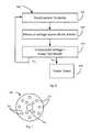
- a method of operating an electrolytic cell in a systemincludes providing a fixed current to a current input terminal of the electrolytic cell; monitoring the cell voltage at the current input terminal; comparing the cell voltage to a predetermined threshold to assess the health of the electrolytic cell; and activating a status indicator to communicate the health of the electrolytic cell.
- the predetermined thresholdcomprises a predetermined voltage that indicates that the electrolytic cell is approaching, but has not yet reached, the end of its useful life in the system. In some embodiments, the predetermined threshold comprises a predetermined voltage that indicates that the electrolytic cell has reached the end of its useful life in the system.
- the methodfurther includes deactivating the cell the result of the comparison of the cell voltage exceeds a predetermined voltage that indicates that the electrolytic cell has reached the end of its useful life in the system.
- the systemincludes a pump configured to supply water to the electrolytic cell, and wherein the method further comprising deactivating the pump if the result of the comparison of the cell voltage exceeds a predetermined voltage that indicates that the electrolytic cell has reached the end of its useful life in the system.
- FIGS. 1A-1Cschematically illustrated features of embodiments of an ozone spray bottle
- FIGS. 2A and 2Bschematically illustrate an embodiments of electrolytic cells
- FIGS. 3A and 3Bschematically illustrate certain operational characteristics of an electrolytic cell
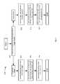
- FIG. 4schematically illustrates circuitry for operating various components of a spray bottle system
- FIG. 5illustrates a method of monitoring and operating an illustrative electrolytic cell
- FIG. 6illustrates a method of monitoring and operating a pump
- FIG. 7schematically illustrates a spray nozzle output
- FIG. 8illustrates a method of operating a spray bottle.
- ozone-spray bottlethat can, among other things, monitor the operation and health of an electrolytic cell and alert the user if the electrolytic cell is not producing sufficient ozone, or if the cell is nearing the end of its useful life so that a replacement cell should be ordered or installed.
- Such featuresreduce the chance that a user incorrectly believes that the bottle is producing ozonated water when, in fact, the bottle is not producing sufficient ozone, or perhaps is not producing ozonated water at all.
- Some embodimentsprovide a spray bottle with a variety of operating modes.
- the sprayermay be controlled to produce ozonated water, or non-ozonated water.
- the sprayermay be controlled to produce spray in one direction, and then controlled to produce spray in a different direction.
- Some embodimentsmay include two or more of the various features described herein.
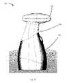
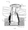
- FIG. 1AOne embodiment of an ozone spray bottle 100 is schematically illustrated in FIG. 1A , an in cross-section in FIG. 1B .
- the spray bottle 100includes a head portion 102 for delivering a stream of ozonated water in a prescribed manner, and a central portion 104 that is preferably shaped to facilitate gripping.
- ozone sprayor “stream of ozonated water” means a fluid flow of water, which water contains ozone when it passes out of a bottle.
- the central portion 104may have a narrower profile with an easily graspable external surface, such as a two-shot injection molded rubber, to provide a more secure and easier grip for the user.
- the bottle 100also has a base portion 106 for containing source water. Components within each of these portions 102 , 104 , and 106 are discussed in greater detail below.
- a trigger 118enables the user to eject ozonated water from the bottle 100 .
- the pump 110draws source water from the tank 107 and pumps the source water into the electrolytic cell 202 .
- the trigger 118also activates the electrolytic cell 202 , causing circuitry to apply an electrical potential to the cell to ozonate the source water.
- the electrolytic cell 202thus produces ozone that virtually immediately is dissolved within the source water. Any number of different cell designs can suffice for this application.
- the pump 110produces a positive force that ejects the ozonated water through the nozzle 116 and out of the spray bottle 100 .
- Illustrative embodimentsalso include a circuit board 126 with a microcontroller, for controlling the functionality of the trigger.
- a sensore.g., a pressure transducer and/or a mechanical switch, as schematically illustrated 490 in FIG. 4 ) detects when the trigger 118 is actuated (e.g., a pressure transducer and/or a mechanical switch), and energizes the appropriate internal components.
- sensorcommunicates with the electronics, which, in turn, communicate with the pump 110 and the electrolytic cell 202 .
- the electronicsactivate the pump 110 and the cell 202 , generating and ejecting ozonated through the nozzle 116 .
- Base portion 106includes a tank 107 for storing water, and supplying source water to the electrolytic cell 202 .
- the tank 107has a water inlet 109 that mates with a threaded plug 108 .
- the threaded plug 108When coupled with the water inlet 109 , the threaded plug 108 provides a water-tight seal, preventing water from escaping from tank 107 .
- the plug 108may also include a knob or dial so that the user can more easily thread the plug into the water inlet 109 .
- a pump 110within the central portion 104 drives the entire fluid path within the bottle 100 .
- the pump 110draws the source water from the tank 107 and toward the electrolytic cell 202 through a hose 180 between the pump inlet 112 and the tank 107 .
- a second hose 181thus directs water from a pump outlet 114 to the electrolytic cell 202 .
- the pump 110draws source water from the tank 107 , into the electrolytic cell 202 , and eventually, after it is ozonated, out of the bottle 100 through an outlet in the head portion 102 (i.e., a nozzle 116 ).
- the spray bottle 100also may have an internal filter 182 that removes scale and other impurities from the source water.
- the filterpreferably is positioned to filter source water before it enters the electrolytic cell 202 .
- the filter 182may be located within the tank 107 , consequently filtering the source water before it flows to the pump 110 .
- the filter 182can be located between the outlet of the pump 114 and the electrolytic cell 202 .
- the base portion 106also includes an electronics chamber 170 .
- the electronics chambermay house, among other things, a power source to provide power to the electrolytic cell 202 and other electronics of the bottle, as well as a circuit board 126 bearing portions of the circuitry described herein.
- a variety of different power sourcescan energize the bottle 100 .
- a hard-wired AC convertercan receive power from a conventional wall plug.
- six 1.2 volt batteries 124 within a chamber 170 underneath the tank 107provide the power for the spray bottle 100 .
- Some embodimentssimply use non-rechargeable batteries.
- Other embodiments, however,use rechargeable batteries that can be charged directly through a hard wire connection, such as a power cord.
- inductive componentsrecharge the rechargeable batteries 124 .
- the spray bottle 100can be placed within charging base station having an inductive coil that charges the batteries 124 .
- the head portion 102 , central portion 104 , and base portion 106are coupled together using a rod 134 .
- the rod 134 and the housing 136provide structural integrity for the spray bottle 100 .
- the rod 134includes a threaded feature (e.g., 134 T) so that the rod is removably coupleable to the head portion 102 , central portion 104 , and/or base portion 106 . In this manner, the rod 134 can be removed from the spray bottle assembly 100 and the components of the spray bottle 100 can be disassembled.
- the interior of the rodcan serve as a conduit for wires or other components.
- the spray bottle 100includes an electrolytic cell 202 for ozonating source water to be delivered through a nozzle 116 (discussed in detail below). Both the nozzle 116 and cell 202 may be within the head portion 102 , although either one can be in other areas. For example, the cell 202 could be within the central portion 104 or base portion 106 .
- the electrolytic cell 202may has two electrodes: an anode 202 A and a cathode 202 C.
- energizing circuitryapplies a positive electric potential to the anode and a negative electric potential to the cathode.
- the difference in electric potential between these two electrodesbreaks up water molecules into hydrogen cations and oxygen.
- the oxygenforms into ozone, which dissolves into the source water.
- the negative potential applied to the cathodedraws the hydrogen cations from the anode side of the cell to the cathode side. Once on the cathode side of the cell, the cations may form hydrogen bubbles.
- the anode 202 A and/or the cathode 202 Cmay have planar configurations.
- the anode 202 A and cathode 202 Cmay be formed from a variety of materials.
- the cathode 202 Cmay be formed from titanium or another conductive material, although these materials do not form an exclusive list of materials from which the cathode 202 C may be fabricated
- the anode 202 Amay be a diamond material.
- the anode 202 Amay be formed from a boron doped diamond material.
- the anode 202 Aincludes a coated diamond material (e.g., a substrate that is coated with a diamond material), while in other embodiments, the anode comprises a free standing diamond material.
- the free standing diamond materialhas a thickness of between 0.2 mm to 1.0 mm.
- both electrodes of the electrolytic cell 202include a boron doped diamond material, as schematically illustrated in cell 201 in FIG. 2B .
- one or both electrodes ( 202 D and 202 E)may include a free standing diamond material or a coated diamond material.
- the electrolytic cell 202may cycle between a positive potential on a first electrode, and then a positive potential on a second electrode. Such a cycle need not be periodic.
- the cell 202When a positive potential is applied to the first diamond electrode, it acts as the anode and the second diamond electrode acts as the cathode. When the polarity is reversed and the positive potential is applied to the second diamond electrode, then the first diamond electrode acts as the cathode and the second diamond electrode acts as the anode. In this manner, the cell 202 continuously produces ozone while cycling through the differing polarities. Reversing the polarity across the electrolytic cell 202 may prevent build-up of scale on the membrane and other cell components.
- a membrane 202 Mis sandwiched between the anode and cathode, as schematically illustrated in both FIG. 2A and FIG. 2B .
- the membrane 202 Mis used as a solid electrolyte and placed between the two electrodes 202 A and 202 C (e.g., a proton exchange membrane (PEM), such as Nafion®) to facilitate movement of protons between the anode 202 A and cathode 202 C.
- PEMproton exchange membrane
- the membrane 202 Mmay also include a supporting matrix.
- the membrane 202 Mis used as a barrier to separate water flow on the cathode side of the cell 300 from water on the anode side of the cell.
- membrane 202 Mserves to define two separate water paths. Water entering the cell 202 is diverted either to the anode side 205 , or to the cathode side 206 of the cell 202 . Water on the anode side 205 is electrolyzed, and the oxygen atoms form ozone and dissolve into the water. The hydrogen atoms pass through the membrane 202 M to the cathode side 206 .
- the water flowing in the anode side 205 of the cell 202exits the cell 202 and ultimately leaves the bottle 100 through nozzle 116 , without being recombined with the water on the cathode side 206 of the cell 202 .
- the water on the cathode side 206along with the hydrogen released by the electrolysis, is returned to the tank 107 via a path 208 separate from the path 207 taken by the ozonated water.
- a path 208separate from the path 207 taken by the ozonated water.
- the cell 202requires electrical power to electrolyze the water flowing through it.
- Prior art electrolytic cellshave been powered by voltage sources. However, the inventors have discovered that the ozone-production capacity of an electrolytic cell may degrade over time, so that the drive voltage supplied to the cell yields progressively less ozone production at the cell ages.
- This phenomenonmay be due, for example, to the build-up of scale in the cell 202 .
- Prior art drive circuitshave addressed the problem of scale build-up by periodically reversing the polarity of the voltage applied to the cell.
- a first electrode in the cellacts as the anode and a second electrode acts as the cathode, but when the polarity of the drive voltage is reversed, the first electrode acts as the cathode while the second electrode acts as the anode. While such an approach extends the life of the cell, it does not prevent scale build-up entirely, and therefore the ozone-production capacity of an electrolytic cell driven by a voltage source inevitably decays with use.
- some embodimentsdrive the electrolytic cell 202 with a current source, which supplies a desired current to the anode 202 A.
- the currentis controlled, and the voltage varies as required to maintain the desired current flow, and thus the desired ozone production.
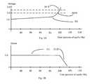
- FIGS. 3A and 3BThe operating characteristics of such a cell are schematically illustrated by FIGS. 3A and 3B .
- the voltage supplied to the cell 220 by the current sourceremains substantially constant at a nominal value.
- the voltage axis in the graph of FIG. 3Aexpresses the voltage supplied by the current source as a ratio of that voltage to the nominal voltage.
- the time axes in FIG. 3A and FIG. 3Bare expressed as percentages of the “useful life” of an electrolytic cell.
- the voltage 301 required to maintain ozone production 311rises as the electrolytic cell ages. However, given the constant current drive, the ozone production 311 remains substantially constant for most of the cell's lifetime, as shown in FIG. 3B .
- the rising drive voltageyields information about the operation of the electrolytic cell. Indeed, the rising drive voltage signals that the cell is nearing the end of its useful life.
- the end of the useful life” of an electrolytic cellis defined as the point at which the cell can no longer produce the desired amount of ozone given the defined drive current and a maximum drive voltage.
- a maximum drive voltagemay be defined as the maximum voltage that the driving current source can provide, and represents a real limitation in real-world circuits.
- the ozone production of the celldrops off 311 D, as shown in FIG. 3B .
- the drive voltagemay be monitored to assess the health of the electrolytic cell. For example, a drive voltage that is twice the nominal drive voltage ( 301 W) may indicate that the cell has reached 97 percent of its useful life. At this point, the cell continues to produce the desired amount of ozone, but it may be prudent to alert the user that the cell is approaching its end of life.
- a drive voltage 301 that is 2.5 times the nominal drive voltage ( 301 R)may indicate that the cell has reached the end of its useful life.
- the cellmay be producing some ozone, but its production is less than the desired amount of ozone. As such, it may be prudent to alert the user that the cell has reached its end of life.
- FIGS. 3A and 3Bare merely illustrative. Actual voltages, voltage ratios and ozone production characteristics will depend on the particular cell being used, and the characteristics of the system in which the cell is being used, such as maximum available drive voltage, for example.
- FIG. 4An embodiment of a circuit for driving and monitoring an electrolytic cell is schematically illustrated in FIG. 4 .
- the heart of this embodimentis a microcontroller 401 , such as the PIC16F1829, available from Microchip Technology Inc., for example, although other microcontrollers or circuits could also be used.
- Microcontroller 401has a programmable CPU, and includes, among other things, digital memory, comparators, an analog-to-digital (A/D) converter, communications interfaces (such as an I/C bus interface or RS232 interface, for example), and various input and output terminals.
- A/Danalog-to-digital
- a current source 431outputs a fixed current to the electrolytic cell 202 , through a set of relay circuits 432 and 433 .
- the two relays in relay circuit 433control the application of the current to the cell 202 , under the control of microcontroller 401 via control line 435 .
- current from current source 431is coupled to cell terminal 402 B, while cell terminal 402 A is coupled to ground. If the relays in relay circuit 433 were switched to their other positions, terminals 402 A and 402 B would not be connected to the current source or to ground. As such, relay circuit 433 acts to enable or disable electrolytic cell 202 .
- Relay circuit 432controls the polarity of the application of the current to the cell 202 , under the control of microcontroller 401 via control line 434 .
- current from current source 431is coupled to cell terminal 402 B, while cell terminal 402 A is coupled to ground. If the relays in relay circuit 432 were switched to their other positions, the current from the current source would be coupled to cell terminal 402 A, while cell terminal 402 B would be coupled to ground. In this way, the polarity of the drive power to the cell 202 can be controllably reversed, for reasons described above.
- the amplitude of the currentis specified as that amount of current that will produce the desired amount of ozone in the electrolytic cell 202 .
- the desired amount of currentis a function of specific electrolytic cell and the quantity of ozone production desired.
- the current source 431is a switching power supply that boosts the battery voltage to a voltage necessary to drive the cell 202 at the fixed current.
- the cell voltage, and optionally the cell currentis monitored to assess the operation and/or health of the cell.
- one or more of the electrical parameters of the power provided to or drawn by an electrolytic cellmay be monitored (for example, using the circuits and methods described below in connection with voltage divider 450 and shunt resistor 440 ) to assess whether the cell is producing ozone (for example, whether the current and/or voltage to the cell are within the nominal ranges for example as illustrated in FIGS. 3A and 3B ). If so, a monitoring circuit may indicate the operational status of the cell by activating a status indicator (such as light 459 , for example). Alternately, a status indicator could be activated if the operation of the assessment indicates that the cell is not producing ozone.
- a status indicatorsuch as light 459 , for example
- the voltage supplied to the cell 202may be monitored through resistor divider 450 , although other circuits could be used.
- the voltage at node 451is a fraction of and is proportional to the voltage supplied to the cell 202 , and can be used by microcontroller 401 to assess the operation of the cell, as described above.
- the voltage at node 451may be supplied to the A/D converter in microcontroller 401 .
- microcontroller 401is programmed to assess the measured drive voltage as part of the process 500 illustrated in FIG. 5 .
- the process 500begins by supplying the fixed drive current to the electrolytic cell (step 501 ).
- the programmed microcontroller 401under control of software, may close the relays in relay circuits 432 and 433 so as to couple the current source 431 to the cell 202 as shown in FIG. 4 .
- the process 500then measures the voltage across the cell (step 502 ), and compares the measured voltage to a first threshold voltage, which may be known as a “Replacement Threshold” (step 503 ).
- the Replacement Thresholdis a voltage that indicates that the electrolytic cell should be replaced. For example, this may be the voltage at which the cell has reached the end of its useful life, but in any case should be a voltage not greater than the voltage at which the cell has reached the end of its useful life.
- the microcontroller 401may activate a status indicator and/or deactivate the electrolytic cell 202 (for example, by depriving the cell of power by, e.g., interrupting or cutting-off the flow of current to an input terminal of the cell). For example, the microcontroller 401 may illuminate a “replacement” light 455 by outputting an appropriate voltage or current on output terminal 405 at step 504 .
- Other forms of status indicatormay include audible signals, which may be produced by a beeper or a buzzer, or a tactile signal such as may be produced by a vibrating element, to name but a few.
- the process 500compares the measured voltage to a “Warning Threshold” at step 505 .
- the Warning Thresholdis a voltage that indicates that the electrolytic cell is nearing the end of its useful life, and that the user should consider ordering a replacement cell. If the measured voltage meets or exceeds the Warning Threshold, the microcontroller 401 illuminates an “order” light 456 by outputting an appropriate voltage or current on output terminal 406 at step 506 .
- the drive currentis fixed, some embodiments also monitor the drive current to catch possible malfunction of the cell 202 , or other components of the drive circuitry.
- the currentmay be monitored by measuring the voltage across a shunt resistor 440 ; and buffering or amplifying through buffer 441 before digitizing the voltage the A/D converter in microcontroller 401 , via signal line 442 .
- the shunt resistorshould have a small resistance, so as not to cause a large voltage drop between the cell 202 and ground.
- the shunt resistormay have a resistance of 0.1 ohms, for example.
- the currentis measured at the ground terminal of the cell 202 (e.g., through the relay circuits 432 and 433 ), although other embodiments may have the shunt resistor 440 in the current supply line 403 .
- the operation of the spray bottle 100may be characterized by the electrical operation of the pump 110 .
- the pump 110will draw a nominal current when it pumps water from the tank 107 to the electrolytic cell 202 .
- the current drawn by the pumpmay increase substantially if the tank runs dry, such that the pump runs dry.
- Running the pump in such conditionsis undesirable because the pump 110 may be damaged, and possibly because the electrolytic cell 202 may be damaged if there is insufficient water flowing through the cell 202 when the cell is under power. Specifically, if the cell 202 operates without sufficient water, its temperature rises, causing potential damage to its interior. Specifically, a temperature rise within the cell could damage the membrane between the electrodes. For example, some PEM membranes have melting temperatures as low as 100 degrees C.
- some embodimentsalso include electronics that determine when the fluid circuit within the bottle 100 no longer has adequate water to maintain the cell 202 in an appropriate operating range.
- the inventorsdiscovered that one embodiment of the pump 110 draws nearly three times its normal operating current when the tank 107 does not have enough water to adequately supply the cell 202 . This may happen when the tank 107 is empty or when the water level is too low for the tube coupled with the pump input to draw up water. The inventors thus used this phenomenon to detect when water is not being drawn from the tank 107 .
- some embodimentsinclude a circuit to power and monitor the operation of the pump.
- a circuit to power and monitor the operation of the pumpis schematically illustrated in FIG. 4 , in which the pump 110 is controlled by the microcontroller 401 via signal line 461 from terminal 462 . The operation of circuit 460 is described by the process illustrated in FIG. 6 .
- the signal from microcontroller 401activates transistor 463 , which draws current from the batteries 124 through pump 110 (step 601 ).
- the circuitsupplies power to the pump (step 601 ), and the pump should draw a nominal amount of current, or a current within a nominal range. That amount of current will depend, for example, on the operating characteristics of the particular pump, and the quantity of the desired water flow, as established by the system's designer.
- the circuit 461monitors the current through the pump by measuring the voltage (step 602 ) across a low-resistance shunt resistor 470 (e.g., 0.1 ohms for example); and buffering or amplifying through buffer 464 before digitizing the voltage the A/D converter in microcontroller 401 , via signal line 465 .
- the microcontrollerthen compares that voltage to “Pump Threshold” voltage that represents the nominal level (step 603 ).
- the pumpmay be deemed to be functioning normally, and it may be inferred that the tank 107 is still supplying water. As such the process begins again.
- the process at step 604may also include causing the microcontroller to illuminate a warning light ( 458 ) to inform the operator the detected condition.
- the microcontrollermay enable a status indicator to alert the user (e.g., light 459 ).
- the pump 110In addition to driving fluid from the tank 107 and into the cell 202 , the pump 110 also generates the pressure that ejects the ozonated water through the nozzle 116 .
- the nozzle 116may have many configurations, its delivery of ozonated water has a number of constraints due to environmental concerns with gaseous ozone.
- the nozzle 116includes at least one constricted diameter that increases the velocity of the ozonated water as it flows through the nozzle. In this manner, the nozzle 116 increases the application range of ozonated water.
- the nozzle 116includes a plurality of very small holes 701 (e.g., 0.25 mm in diameter).
- the nozzle 116may have multiple holes to create a “shower head” effect (e.g., the nozzle 116 includes six holes that are each 0.25 mm in diameter).
- some embodimentsconfigure the nozzle 116 with a single hole 702 to create a single stream of ozonated water only.
- the nozzle 116is configured so that the user can select between various spray patterns (e.g., single hole 702 or multiple hole).
- the spray bottle 100may have a check 154 valve within the head portion 102 . More specifically, as shown in FIG.
- the bottle 100has a check valve for minimizing the likelihood that water will drain from the electrolytic cell 202 and into the tank 107 when the cell is not in operation.
- the check valve 154preferably is located at a point between the nozzle 116 and the tank 107 (e.g., between the cell 202 and the nozzle 116 ) to retain water within the cell when the pump is not in operation.
- a check valve 155is located in the fluid path between the tank 107 and the electrolytic cell 202 .
- Check valvesmay also be located on the tank to permit selected gaseous exchange between the tank interior and the external environment. Specifically, as shown in FIG. 1B , when the pump 110 draws water from the tank 107 , a check valve 120 may permit air to enter the tank 107 to equalize the pressure within its interior. Without this valve, a negative pressure may build up in the tank 107 , causing stress on the pump and the entire system. Accordingly, the check valve 120 facilitates the flow of water out of the tank 107 and through the fluid paths within the bottle 100 .
- Some embodimentsposition another check valve 122 to exhaust gases that may build up within the tank 107 .
- the check valve 122freely passes hydrogen bubbles from the interior of the tank to the external environment.
- the water with the hydrogen byproduct from the cathode side of the cell 202enters the tank 107 .
- This hydrogen byproductforms bubbles and corresponding gas, which passes through the check valve 122 and out of the tank 107 .
- Pressuremay increase within the tank 107 for a number of other reasons.
- the tank pressuremay increase if the water within the tank 107 vaporizes and/or the air within the tank expands because of a temperature increase.
- This check valve 122thus releases any excess gas to the external environment, thus facilitating operation of the bottle 100 .
- Illustrative embodimentsposition the check valves 120 , 122 near the top of the tank so that hydrogen gas can rise and flow though the check valve.
- the check valves 120 , 122are integrated into the threaded plug 208 .
- the bottlebe selectively controlled to operate simply as a water bottle 100 .
- Illustrative embodimentsthus include functionality that enables the bottle 100 to function in any of a variety of modes.
- the bottle 100acts a spray bottle in one mode, and as an ozone spray dispenser (i.e., like a soap dispenser) in another mode.
- the bottle 100has circuitry that sets the bottle 100 to either one of a “trigger” mode or a “dispensing” mode.
- the bottle 100ejects ozonated water in response to actuation of the trigger 118 —it acts as a spray bottle.
- the bottle 100ejects ozonated water in response to actuation of a dispensing sensor 128 —it acts like a soap dispenser (even though it dispenses ozonated water).
- the dispensing sensor 128may be located on the underside of the head portion 102 of the bottle 100 .
- the dispensing sensor 128is a non-contact sensor, such as an infra-red sensor, an electro-optical sensor, and/or a motion sensor.
- the sensor 128can be a tactile sensor, such a switch, a pressure sensor and/or a piezoelectric sensor.
- the nozzle 116may be configurable to selectively deliver ozonated water in at least two different directions relative to the tank 107 .
- the nozzle 116in trigger mode, is configured so that water is ejected generally in a forward direction as shown by arrow 130 in FIG. 1B .
- the bottle 100In dispensing mode, however, the bottle 100 is configured to dispense water generally in a downward direction as shown by arrow 132 (or at an angle) by pivoting the nozzle 116 .
- the streammay be in the form of multiple streams (e.g., like a showerhead) in parallel or diverging paths.
- the nozzle 116is configured to pivot and the user manually adjusts the direction of the nozzle.
- the bottle 100automatically pivots the nozzle 116 using, for example, an electric motor and/or an electronic actuator.
- the bottle 100when in the trigger mode, the bottle 100 acts much like a spray bottle and applies ozonated water to remote surfaces (e.g., counter tops, stove tops, sinks, and tables), while, in the dispensing mode, the bottle 100 acts similarly to a soap dispenser.
- the dispensing modewhen the user places his hand on the underside of the head portion 102 of the bottle 100 , the dispensing sensor 128 detects the presence of the user's hand, and ejects ozonated water downwardly onto the user's hand. In this manner, the user can disinfect his hand and/or apply ozonated water to cleaning utensils (e.g., sponges, rags, and/or paper towels).
- cleaning utensilse.g., sponges, rags, and/or paper towels.
- the bottle 100also includes a mode switch 156 so that the user can switch between the dispensing mode and the trigger mode.
- the switch 156is located on the top of the head portion 102 of the bottle 100 .
- the bottle 100includes visual indicia (such as LED lights, e.g., 457 ) for indicating the mode to which the bottle 100 is set.
- the bottle 100thus includes electronics/circuitry (such as circuit board 152 ) for selecting between the dispensing mode and a trigger mode.
- FIG. 8shows a process 800 for setting either the dispensing mode or the trigger mode in accordance with one embodiment of the present invention.
- the spray bottle circuitrydetermines whether the mode switch 156 is set to the dispensing mode or the trigger mode (step 802 ) by the user. In other words, the circuitry that is in communication with the mode switch 156 is responsive to selection of the mode switch by the user. If the user sets the switch 156 to the dispensing mode, then the circuitry activates the dispensing sensor 128 and deactivates the trigger 118 (step 804 ).
- the circuitryawaits actuation of the dispensing sensor 128 to initiate ejection of the ozonated water, while the trigger 118 is inactive and cannot be used to initiate ejection of ozonated water.
- the electronicsactivate the pump 110 , and the electrolytic cell 202 so that the bottle 100 can eject ozonated water in the prescribed direction (step 806 ).
- the electronicsdeactivate the pump 110 and the electrolytic cell 202 (step 808 ). In other embodiments, however, the electronics deactivate the pump 110 and the electrolytic cell 202 only after the dispensing sensor 128 is no longer being actuated by the user.
- the electronicsactivate the trigger 118 and deactivate the dispensing sensor 128 , (step 810 ).
- the electronicsawait actuation of the trigger 118 to initiate ejection of the ozonated water, while the dispensing sensor 128 is inactive and cannot be used to initiate ejection of ozonated water.
- the electronicsactivate the pump 110 and the electrolytic cell 202 so that the bottle 100 can eject ozonated water (step 812 ). Once the user releases the trigger 118 , the electronics deactivate the pump 110 and the electrolytic cell 202 (step 714 ).
- the electronicsmay also be configured to communicate with an electrical motor and/or electronic actuator for pivoting the nozzle 116 .
- the nozzle 116is pivoted so that it ejects ozonated water in a downward direction.
- some embodimentsmay add a surfactant to the water prior to ozonating the water, so as to produce water that includes both ozone and surfactant.
- a surfactantmay produce several benefits. For example, it some surfactants are known to increase the life of ozone in water. Also, while ozone has known disinfecting properties, the cleaning effect of the water may be increased by including a surfactant, such as sodium dodecyl sulfate (“SDS”), for example.
- SDSsodium dodecyl sulfate
- ozonate wateror a fluid including water, is to decompose at least some of the molecules of water such that the oxygen atoms form ozone, which ozone remains in the water.
- the “parameters” of electrical power provided to an electrolytic cellincludes the voltage supplied to the cell and the current drawn by the cell.
- the voltage and currentare each a “parameter.”
- the “operational status” of an electrolytic cellindicates whether (or not) the electrolytic cell is producing ozone.
- the “lifetime status” of an electrolytic cellindicates whether the electrolytic cell is nearing, or has reached, the end of its useful life. For example, an electrolytic cell that draws a voltage in excess of a first pre-determined threshold may be deemed to be nearing the end of its useful life, and an electrolytic cell that draws a voltage equal to or in excess of a higher, second pre-determined voltage may be deemed to have reached or surpassed the end of its useful life.
- the “useful life” of an electrolytic cellis the time during which the cell can produce ozone while drawing less than a pre-determined amount of power from a power source.
- the voltage drawn by the electrolytic cellmay be used as a proxy for the power drawn by the cell, and a pre-determined voltage may be used as a proxy for the pre-determined power drawn by the cell.
- the pre-determined power or voltagemay be specified by the system designer based on factors such as maximum available power or voltage, or the available heat dissipation properties of the electrolytic cell or a device or system housing the cell, or the ozone-producing capacity of the electrolytic cell, to name but a few.
- the term “useful life”may not be an absolute term. Rather, it may depend at least in part on the context or system in which an electrolytic cell is used, and/or how the electrolytic cell is used.
- a bottle for applying ozonated water to a surfacecomprising:
- a tankhaving an interior for containing water
- a nozzle for directing ozonated water out of the spray bottlewherein the nozzle comprises a plurality of apertures in fluid communication with an electrolytic cell, each aperture having a diameter of not less than 0.25 mm;
- the electrolytic celllocated between the nozzle and the tank, the electrolytic cell configured to ozonate water as the water flows from the tank to the nozzle.
- embodiments of the inventionmay be implemented at least in part in any conventional computer programming language. For example, some embodiments may be implemented in a procedural programming language (e.g., “C”), or in an object oriented programming language (e.g., “C++”). Other embodiments of the invention may be implemented as preprogrammed hardware elements (e.g., application specific integrated circuits, FPGAs, and digital signal processors), or other related components.
- Cprocedural programming language
- object oriented programming languagee.g., “C++”.
- preprogrammed hardware elementse.g., application specific integrated circuits, FPGAs, and digital signal processors
- the disclosed apparatus and methodsmay be implemented as a computer program product for use with a computer system.
- Such implementationmay include a series of computer instructions fixed either on a tangible medium, such as a non-transient computer readable medium (e.g., a diskette, CD-ROM, ROM, or fixed disk).
- the series of computer instructionscan embody all or part of the functionality previously described herein with respect to the system.
- Such computer instructionscan be written in a number of programming languages for use with many computer architectures or operating systems.
- such instructionsmay be stored in any memory device, such as semiconductor, magnetic, optical or other memory devices, and may be transmitted using any communications technology, such as optical, infrared, microwave, or other transmission technologies.
- such a computer program productmay be distributed as a removable medium with accompanying printed or electronic documentation (e.g., shrink wrapped software), preloaded with a computer system (e.g., on system ROM or fixed disk), or distributed from a server or electronic bulletin board over the network (e.g., the Internet or World Wide Web).
- a computer systeme.g., on system ROM or fixed disk
- a server or electronic bulletin boardover the network (e.g., the Internet or World Wide Web).
- some embodiments of the inventionmay be implemented as a combination of both software (e.g., a computer program product) and hardware. Still other embodiments of the invention are implemented as entirely hardware, or entirely software.
- a process that is completely or partially implemented on a computer, microprocessor, or microcontrolleris the performance of a described function in a computer using computer hardware (such as a processor, field-programmable gate array or other electronic combinatorial logic, or similar device), which may be operating under control of software or firmware or a combination of any of these or operating outside control of any of the foregoing. All or part of the described function may be performed by active or passive electronic components, such as transistors or resistors.
- a computer processwe do not necessarily require a schedulable entity, or operation of a computer program or a part thereof, although, in some embodiments, a computer process may be implemented by such a schedulable entity, or operation of a computer program or a part thereof. Furthermore, unless the context otherwise requires, a “process” may be implemented using more than one processor or more than one (single- or multi-processor) computer.
Landscapes
- Chemical & Material Sciences (AREA)
- Organic Chemistry (AREA)
- Engineering & Computer Science (AREA)
- Water Supply & Treatment (AREA)
- Hydrology & Water Resources (AREA)
- Environmental & Geological Engineering (AREA)
- Electrochemistry (AREA)
- Chemical Kinetics & Catalysis (AREA)
- Life Sciences & Earth Sciences (AREA)
- Metallurgy (AREA)
- Materials Engineering (AREA)
- Inorganic Chemistry (AREA)
- General Chemical & Material Sciences (AREA)
- Automation & Control Theory (AREA)
- Water Treatment By Electricity Or Magnetism (AREA)
- Apparatus For Disinfection Or Sterilisation (AREA)
- Treatment Of Water By Oxidation Or Reduction (AREA)
- Electrolytic Production Of Non-Metals, Compounds, Apparatuses Therefor (AREA)
Abstract
Description
Claims (20)
Priority Applications (1)
| Application Number | Priority Date | Filing Date | Title |
|---|---|---|---|
| US13/594,578US9540259B2 (en) | 2011-08-25 | 2012-08-24 | Apparatus for producing and delivering ozonated water |
Applications Claiming Priority (2)
| Application Number | Priority Date | Filing Date | Title |
|---|---|---|---|
| US201161527402P | 2011-08-25 | 2011-08-25 | |
| US13/594,578US9540259B2 (en) | 2011-08-25 | 2012-08-24 | Apparatus for producing and delivering ozonated water |
Publications (2)
| Publication Number | Publication Date |
|---|---|
| US20130206604A1 US20130206604A1 (en) | 2013-08-15 |
| US9540259B2true US9540259B2 (en) | 2017-01-10 |
Family
ID=47046825
Family Applications (1)
| Application Number | Title | Priority Date | Filing Date |
|---|---|---|---|
| US13/594,578Expired - Fee RelatedUS9540259B2 (en) | 2011-08-25 | 2012-08-24 | Apparatus for producing and delivering ozonated water |
Country Status (8)
| Country | Link |
|---|---|
| US (1) | US9540259B2 (en) |
| EP (1) | EP2748113B1 (en) |
| JP (2) | JP2014526969A (en) |
| CN (2) | CN106006851B (en) |
| ES (1) | ES2691732T3 (en) |
| HU (1) | HUE039842T2 (en) |
| PL (1) | PL2748113T3 (en) |
| WO (1) | WO2013029019A2 (en) |
Cited By (5)
| Publication number | Priority date | Publication date | Assignee | Title |
|---|---|---|---|---|
| US10973938B1 (en) | 2020-12-21 | 2021-04-13 | Professional Server Certification Corporation | Insert for sprayer bottle for ozonating water |
| US12012661B2 (en) | 2020-06-27 | 2024-06-18 | Aquamox Inc. | Electrolytic generators |
| TWI851125B (en)* | 2023-03-31 | 2024-08-01 | 陳柏銓 | Rechargeable electrolytic ozone showerhead |
| US12091332B2 (en) | 2020-12-21 | 2024-09-17 | Professional Server Certification Corporation | Apparatus and method for modifying a sprayer bottle into an ozonating sprayer bottle and for making a water reservoir into an ozonated water reservoir |
| US12257357B2 (en) | 2020-12-21 | 2025-03-25 | Professional Server Certification Corporation | Apparatus and method for modifying a sprayer bottle into an ozonating and ionizing water sprayer bottle and for providing humidification with ozonated and ionized water |
Families Citing this family (26)
| Publication number | Priority date | Publication date | Assignee | Title |
|---|---|---|---|---|
| EP2697730A4 (en) | 2011-04-15 | 2015-04-15 | Advanced Diamond Technologies Inc | Electrochemical system and method for on-site generation of oxidants at high current density |
| US9057712B1 (en)* | 2011-10-27 | 2015-06-16 | Copilot Ventures Fund Iii Llc | Methods of delivery of encapsulated perfluorocarbon taggants |
| CN104010120B (en)* | 2014-06-06 | 2017-12-15 | 江苏中讯电子科技有限公司 | Multifunctional network camera |
| US10087084B2 (en) | 2015-03-30 | 2018-10-02 | Roving Blue, Inc. | Automatic flow control based on sensed effectiveness indicators to produce effectively treated water with a portable water treatment unit |
| US10239772B2 (en) | 2015-05-28 | 2019-03-26 | Advanced Diamond Technologies, Inc. | Recycling loop method for preparation of high concentration ozone |
| CN105543885A (en)* | 2016-01-19 | 2016-05-04 | 沈阳溢源设备制造有限公司 | Electrolytic saltwater spray head |
| DE102016104104A1 (en)* | 2016-03-07 | 2017-09-07 | Epcos Ag | Process for the production of ozone and apparatus for ozone generation |
| WO2018003557A1 (en)* | 2016-06-30 | 2018-01-04 | シャープ株式会社 | Mist-generating device, mist-generating method, and sterilization/deodorization method |
| CN106315773B (en)* | 2016-08-29 | 2023-08-04 | 福州品行科技发展有限公司 | Portable dual-purpose hydrogen-rich water bottle and working method thereof |
| EP3529397A4 (en) | 2016-10-20 | 2020-06-24 | Advanced Diamond Technologies, Inc. | Ozone generators, methods of making ozone generators, and methods of generating ozone |
| US10501356B2 (en) | 2016-11-21 | 2019-12-10 | Franke Technology And Trademark Ltd | Hospital ozone faucet |
| GB2557185A (en)* | 2016-11-29 | 2018-06-20 | Roseland Holdings Ltd | Electrochemical cell assembly and method for operation of the same |
| JP6170266B1 (en)* | 2017-03-25 | 2017-07-26 | 伯東株式会社 | Ozone water production apparatus, ozone water production method, and sterilization method using ozone water |
| DE102017210854A1 (en) | 2017-06-28 | 2019-01-03 | Robert Bosch Gmbh | Ozonnebler |
| WO2020018983A1 (en)* | 2018-07-20 | 2020-01-23 | Enozo Technologies, Inc. | High efficiency electrolytic ozone production system |
| IT201900005488A1 (en)* | 2019-04-10 | 2020-10-10 | Tand S S R L S | SPRAYER APPARATUS |
| US20210138099A1 (en)* | 2019-11-13 | 2021-05-13 | Scentlok Technologies, Inc. | Method of concealing outdoor equipment |
| JP7464953B2 (en)* | 2019-12-26 | 2024-04-10 | 青島海爾洗衣机有限公司 | Ozone water spraying device |
| US11279618B2 (en)* | 2020-03-05 | 2022-03-22 | Cashido Corporation | Ozone water supply apparatus and ozone generation device |
| CN111214684B (en)* | 2020-03-06 | 2023-08-01 | 广州德百顺蓝钻科技有限公司 | Ozone water disinfection spray bottle |
| WO2021252366A2 (en)* | 2020-06-08 | 2021-12-16 | Enozo Technologies, Inc. | Ozone spray wand |
| JP7629160B2 (en)* | 2020-08-21 | 2025-02-13 | 青島海爾洗衣机有限公司 | Deodorizing equipment |
| JP7645505B2 (en)* | 2020-09-17 | 2025-03-14 | 青島海爾洗衣机有限公司 | Ozone water spraying device |
| JP7572673B2 (en)* | 2020-09-17 | 2024-10-24 | 青島海爾洗衣机有限公司 | Ozone water spraying device |
| KR102506983B1 (en)* | 2020-10-05 | 2023-03-07 | 계명대학교 산학협력단 | A personal automatic ozonated water sprayer for virus prevention and sterilization and its use method |
| FR3140872A1 (en)* | 2022-10-18 | 2024-04-19 | Weo Llc. | Water bottle comprising a water function augmentation device |
Citations (85)
| Publication number | Priority date | Publication date | Assignee | Title |
|---|---|---|---|---|
| US5051161A (en)* | 1989-06-30 | 1991-09-24 | Nippon Intek Co., Ltd. | Apparatus producing continuously electrolyzed water |
| US5106495A (en)* | 1991-07-12 | 1992-04-21 | Harold Hughes | Portable water purification device |
| US5314589A (en) | 1992-10-15 | 1994-05-24 | Hawley Macdonald | Ion generator and method of generating ions |
| JPH06328071A (en) | 1993-05-20 | 1994-11-29 | Nippon Intetsuku Kk | Electrode life determination device for electrolyzed ionic water generation device |
| EP0636581A1 (en) | 1993-07-30 | 1995-02-01 | MIZ Co., Ltd. | Electrolyzed water producing method and apparatus |
| JPH0731977A (en) | 1993-07-22 | 1995-02-03 | Akai Electric Co Ltd | Electrolyzed ion forming device |
| US5858201A (en) | 1994-07-29 | 1999-01-12 | Toto, Ltd. | Strong acid sterilizing liquid containing hypochlorous acid at a low concentration, method and apparatus for generating same, and apparatus for generating and dispensing same |
| JPH1110159A (en) | 1997-06-26 | 1999-01-19 | Matsushita Electric Works Ltd | Apparatus for producing electrolytic solution |
| US5971368A (en) | 1997-10-29 | 1999-10-26 | Fsi International, Inc. | System to increase the quantity of dissolved gas in a liquid and to maintain the increased quantity of dissolved gas in the liquid until utilized |
| US6007693A (en)* | 1995-03-30 | 1999-12-28 | Bioquest | Spa halogen generator and method of operating |
| WO2000005561A1 (en) | 1998-07-22 | 2000-02-03 | Oliver Rubber Company | Tire inspection equipment and method |
| WO2000035813A1 (en) | 1998-12-16 | 2000-06-22 | Lynntech, Inc. | Microorganism control of point-of-use potable water sources |
| US6110431A (en) | 1997-05-05 | 2000-08-29 | Dunder; Ove Karl | Ozone dispensing system |
| US6261464B1 (en) | 1999-05-25 | 2001-07-17 | Miox Corporation | Portable water disinfection system |
| EP1162176A1 (en) | 2000-06-08 | 2001-12-12 | Mikuni Corporation | Electrolyzed water of anode side and process for production thereof |
| US20020020675A1 (en) | 1999-05-25 | 2002-02-21 | Herrington Rodney E. | Portable water disinfection system |
| US6361686B1 (en) | 1999-10-14 | 2002-03-26 | Fantom Technologies Inc. | Construction of a water treatment reservoir for a domestic water treatment appliance |
| US6391183B1 (en) | 1997-12-10 | 2002-05-21 | Shinko Plant Construction Co., Ltd. | Apparatus for producing ozone water and method of producing ozone water by using the same apparatus |
| US20020141915A1 (en)* | 2001-01-29 | 2002-10-03 | Marco Equipment Distributors, Inc. | Apparatus and method for generating and circulating ozone for disinfection/steriIization of dental waterlines and also providing an independent source of disinfected/sterilized water for dental applications |
| US20020185423A1 (en) | 2000-12-12 | 2002-12-12 | Boyd Brian T. | Device and method for generating and applying ozonated water |
| WO2002102716A1 (en) | 2001-06-14 | 2002-12-27 | Rmg Services Pty Ltd | Electrolytic activation of fluids |
| US6524475B1 (en) | 1999-05-25 | 2003-02-25 | Miox Corporation | Portable water disinfection system |
| JP2003062573A (en) | 2001-08-29 | 2003-03-04 | Mikuni Corp | Electrolytic water generator |
| US6527950B2 (en) | 1999-10-14 | 2003-03-04 | Chiaphua Industries Limited | Construction of a water treatment appliance |
| US20030062267A1 (en)* | 2001-05-25 | 2003-04-03 | Shinichi Nakamura | Method for generating sterilizing wash water and a portable apparatus thereof |
| WO2003028773A1 (en) | 2001-10-04 | 2003-04-10 | The Johns Hopkins University | Airborne pathogen neutralization |
| US6551490B2 (en) | 1997-03-31 | 2003-04-22 | Lynntech International, Ltd. | Generation and delivery device for ozone gas and ozone dissolved in water |
| US6558537B1 (en) | 1999-05-25 | 2003-05-06 | Miox Corporation | Portable hydration system |
| US20030156978A1 (en) | 2001-11-26 | 2003-08-21 | Gillette Thomas D. | Method and device for providing ozone sanitation of various objects |
| US6652719B1 (en) | 2002-06-03 | 2003-11-25 | Skydon Corp. | Electrolysis system |
| US20040011723A1 (en) | 2000-09-05 | 2004-01-22 | Bradford Wesley L. | Filtration membrane and method of making same |
| JP2004060010A (en) | 2002-07-30 | 2004-02-26 | Neo Ozone Kk | Ozone water production equipment |
| JP2004130264A (en) | 2002-10-11 | 2004-04-30 | Kao Corp | Method for producing electrolyzed water |
| US20040173528A1 (en) | 1999-05-25 | 2004-09-09 | Miox Corporation | Pumps for filtration systems |
| US20040178145A1 (en) | 1999-05-25 | 2004-09-16 | Miox Corporation | Dual head pump driven filtration system |
| JP2004283662A (en) | 2003-03-19 | 2004-10-14 | Fuji Electric Retail Systems Co Ltd | Residual chlorine concentration maintaining device |
| US20040211676A1 (en) | 2001-07-16 | 2004-10-28 | Miox Corporation | Electrolytic cell for surface and point of use disinfection |
| US20040226873A1 (en) | 2001-07-16 | 2004-11-18 | Miox Corporation | Gas drive electrolytic cell |
| US20050005954A1 (en) | 2001-10-16 | 2005-01-13 | Ruggero Barani | Apparatus and process for washing drying and sterilising industrial plants |
| US20050017380A1 (en) | 2003-06-26 | 2005-01-27 | Namespetra Justin L. | Sanitization system and system components |
| WO2005093129A1 (en) | 2004-02-27 | 2005-10-06 | Barbin-Harper Llc | Production of electrolytic water |
| EP1251893B1 (en) | 1999-09-03 | 2005-10-19 | Therakos, Inc. | Uninterrupted flow pump apparatus and method |
| US20050252844A1 (en)* | 2004-05-14 | 2005-11-17 | Chau Yiu C | Water treatment unit for bottle or pitcher |
| US20060037869A1 (en) | 2004-08-19 | 2006-02-23 | Miox Corporation | Scented electrolysis product |
| US20060157343A1 (en)* | 2001-07-16 | 2006-07-20 | Miox Corporation | Electrolytic cell for surface and point of use disinfection |
| US20060163174A1 (en) | 2003-06-26 | 2006-07-27 | Namespetra Justin L | System and containers for water filtration and item sanitization |
| CN1899975A (en) | 2005-06-16 | 2007-01-24 | 培尔梅烈克电极股份有限公司 | Method of sterilization and electrolytic water ejecting apparatus |
| EP1754804A1 (en) | 2004-04-28 | 2007-02-21 | Central Japan Railway Company | Electrode, ozone generator and ozone generating method |
| US20070086913A1 (en) | 2004-11-11 | 2007-04-19 | Ajt & Associates, Inc. | Ozone Disinfection Apparatus |
| US7235169B2 (en) | 2001-12-28 | 2007-06-26 | Omega Co., Ltd. | Method and apparatus for purging and disinfecting water |
| US7238278B2 (en) | 2001-10-26 | 2007-07-03 | Zodiac Pool Care, Inc. | Apparatus for purifying water |
| WO2007092597A2 (en) | 2006-02-10 | 2007-08-16 | Tennant Company | Electrochemically activated anolyte and catholyte liquid |
| WO2007093395A2 (en) | 2006-02-17 | 2007-08-23 | Actides Gmbh | Process for producing a disinfectant by electrochemical activation (eca) of water, disinfectant produced in such a manner and use thereof |
| WO2007095074A1 (en) | 2006-02-10 | 2007-08-23 | Tennant Company | Method and apparatus for producing humanly-perceptable indicator of electrochemical properties of an output cleaning liquid |
| WO2007095072A1 (en) | 2006-02-10 | 2007-08-23 | Tennant Company | Cleaning apparatus having a functional generator, and method for producing electrochemically activated cleaning liquid |
| WO2007095073A1 (en) | 2006-02-10 | 2007-08-23 | Tennant Company | Method and apparatus for generating, applying and neutralizing an electrochemically activated liquid |
| WO2007095094A1 (en) | 2006-02-10 | 2007-08-23 | Tennant Company | Method and apparatus for generating sparged, electrochemically activated liquid |
| US20070207073A1 (en) | 2006-03-03 | 2007-09-06 | Drucker Tod H | Apparatus for supporting and disinfecting a handheld instrument and/or a portion of the user's hand |
| JP2007239041A (en) | 2006-03-09 | 2007-09-20 | Central Japan Railway Co | Ozone mist generating apparatus |
| WO2007117351A2 (en) | 2006-02-10 | 2007-10-18 | Tennant Company | Mobile surface cleaner having a sparging device, and method of producing a sparged cleaning liquid onboard a mobile surface cleaner |
| US20080067078A1 (en)* | 2006-09-20 | 2008-03-20 | Permelec Electrode Ltd. | Membrane-electrode assembly, electrolytic unit using the same, electrolytic water ejecting apparatus, and method of sterilization |
| US20080128353A1 (en) | 2005-01-06 | 2008-06-05 | Andelman Marc D | Surfactant Combined Flow Through Capacitor |
| US20080190825A1 (en)* | 2005-03-18 | 2008-08-14 | Tersano Inc. | Water Sanitazation System Having Safety Features and Removable Filter |
| US20080210572A1 (en) | 2006-02-10 | 2008-09-04 | Tennant Company | Hand-held spray bottle having an electrolyzer and method therefor |
| US20080237368A1 (en) | 2005-03-18 | 2008-10-02 | Tersano Inc. | Ozonated Water Dispenser |
| US20080302651A1 (en)* | 2004-08-11 | 2008-12-11 | Miz Co., Ltd. | Performance Maintaining Method For Electrolyzed Functional Water Generating Apparatus |
| WO2009011841A1 (en) | 2007-07-13 | 2009-01-22 | Ceramatec, Inc. | Cleansing agent generator and dispenser |
| US20090039032A1 (en) | 2007-08-07 | 2009-02-12 | Whirlpool Corporation | Portable filtration and ozonation apparatus |
| US20090039033A1 (en) | 2007-08-07 | 2009-02-12 | Whirlpool Corporation | Portable ozonation apparatus for storing and purifying liquid |
| US20090071331A1 (en) | 2001-11-26 | 2009-03-19 | Gillette Thomas D | Systems and methods for reducing off-gassed ozone |
| US20090072052A1 (en) | 2001-11-26 | 2009-03-19 | Gillette Thomas D | Systems and methods for producing ozonated water on demand |
| US20090127128A1 (en)* | 2007-11-15 | 2009-05-21 | Permelec Electrode Ltd. | Membrane-electrode assembly, electrolytic cell employing the same, electrolytic-water sprayer, and method of sterilization |
| JP2009125628A (en) | 2007-11-20 | 2009-06-11 | Permelec Electrode Ltd | Membrane-electrode assembly, electrolytic cell using the same, ozone water generator, and sterilization method |
| US20090159436A1 (en) | 2007-12-25 | 2009-06-25 | Mikuni Corporation | Electrolyzed water generating and spraying device |
| CN101498007A (en) | 2007-11-15 | 2009-08-05 | 培尔梅烈克电极股份有限公司 | Membrane-electrode assembly, electrolytic cell employing the same, electrolytic-water sprayer, and method of sterilization |
| US20090212132A1 (en) | 2008-02-26 | 2009-08-27 | Dyson Technology Limited | Spray dispenser |
| US20090314655A1 (en) | 2008-06-19 | 2009-12-24 | Tennant Company | Electrolysis de-scaling method with constant output |
| US20090314659A1 (en) | 2008-06-19 | 2009-12-24 | Tennant Company | Tubular electrolysis cell and corresponding method |
| US20090314645A1 (en) | 2005-04-26 | 2009-12-24 | Chil-Young Kim | Apparatus for manufacturing sterilized water, and portable apparatus for manufacturing sterilized salt solution |
| US7658824B2 (en) | 2003-06-06 | 2010-02-09 | Ben Bremauer | Electrolytic sanitiser generator |
| WO2010055108A1 (en) | 2008-11-13 | 2010-05-20 | Gima S.P.A. | Electrochemical reactor |
| US20100135869A1 (en) | 2007-05-28 | 2010-06-03 | Linxross, Inc. | Ozone generators |
| US20100320082A1 (en) | 2009-06-23 | 2010-12-23 | Chlorine Engineers Corp., Ltd. | Conductive diamond electrode and ozone generator using the same |
| US20110256027A1 (en) | 2010-04-19 | 2011-10-20 | Shih-Chang Chen | Ozonated water spraying system with energy resource conversion, and ozonated water spraying apparatus thereof |
| US20130323605A1 (en)* | 2011-03-04 | 2013-12-05 | Adeka Corporation | Nonaqueous electrolyte solution for batteries, and nonaqueous electrolyte secondary battery using same |
Family Cites Families (2)
| Publication number | Priority date | Publication date | Assignee | Title |
|---|---|---|---|---|
| US20060273016A1 (en)* | 2005-06-03 | 2006-12-07 | BAGLEY David | Method for preparing water with a stable negative oxidation reduction potential (ORP) |
| CN201777951U (en)* | 2010-07-20 | 2011-03-30 | 深圳市兴进环保科技有限公司 | Sewage treatment system |
- 2012
- 2012-08-24JPJP2014527341Apatent/JP2014526969A/enactivePending
- 2012-08-24PLPL12775337Tpatent/PL2748113T3/enunknown
- 2012-08-24ESES12775337.4Tpatent/ES2691732T3/enactiveActive
- 2012-08-24CNCN201610357081.XApatent/CN106006851B/ennot_activeExpired - Fee Related
- 2012-08-24USUS13/594,578patent/US9540259B2/ennot_activeExpired - Fee Related
- 2012-08-24WOPCT/US2012/052381patent/WO2013029019A2/enactiveApplication Filing
- 2012-08-24EPEP12775337.4Apatent/EP2748113B1/enactiveActive
- 2012-08-24CNCN201280048342.XApatent/CN103857630A/enactivePending
- 2012-08-24HUHUE12775337Apatent/HUE039842T2/enunknown
- 2016
- 2016-05-26JPJP2016105040Apatent/JP6166425B2/ennot_activeExpired - Fee Related
Patent Citations (124)
| Publication number | Priority date | Publication date | Assignee | Title |
|---|---|---|---|---|
| US5051161A (en)* | 1989-06-30 | 1991-09-24 | Nippon Intek Co., Ltd. | Apparatus producing continuously electrolyzed water |
| US5106495A (en)* | 1991-07-12 | 1992-04-21 | Harold Hughes | Portable water purification device |
| US5314589A (en) | 1992-10-15 | 1994-05-24 | Hawley Macdonald | Ion generator and method of generating ions |
| JPH06328071A (en) | 1993-05-20 | 1994-11-29 | Nippon Intetsuku Kk | Electrode life determination device for electrolyzed ionic water generation device |
| JPH0731977A (en) | 1993-07-22 | 1995-02-03 | Akai Electric Co Ltd | Electrolyzed ion forming device |
| EP0636581A1 (en) | 1993-07-30 | 1995-02-01 | MIZ Co., Ltd. | Electrolyzed water producing method and apparatus |
| US5858201A (en) | 1994-07-29 | 1999-01-12 | Toto, Ltd. | Strong acid sterilizing liquid containing hypochlorous acid at a low concentration, method and apparatus for generating same, and apparatus for generating and dispensing same |
| US6007693A (en)* | 1995-03-30 | 1999-12-28 | Bioquest | Spa halogen generator and method of operating |
| US6551490B2 (en) | 1997-03-31 | 2003-04-22 | Lynntech International, Ltd. | Generation and delivery device for ozone gas and ozone dissolved in water |
| US20030209447A1 (en)* | 1997-03-31 | 2003-11-13 | Lynntech International, Ltd. | Generation and delivery device for ozone gas and ozone dissolved in water |
| US6110431A (en) | 1997-05-05 | 2000-08-29 | Dunder; Ove Karl | Ozone dispensing system |
| JPH1110159A (en) | 1997-06-26 | 1999-01-19 | Matsushita Electric Works Ltd | Apparatus for producing electrolytic solution |
| US6488271B1 (en) | 1997-10-29 | 2002-12-03 | Fsi International, Inc. | Method to increase the quantity of dissolved gas in a liquid and to maintain the increased quantity of dissolved gas in the liquid until utilized |
| US6648307B2 (en) | 1997-10-29 | 2003-11-18 | Fsi International, Inc. | Method to increase the quantity of dissolved gas in a liquid and to maintain the increased quantity of dissolved gas in the liquid until utilized |
| US5971368A (en) | 1997-10-29 | 1999-10-26 | Fsi International, Inc. | System to increase the quantity of dissolved gas in a liquid and to maintain the increased quantity of dissolved gas in the liquid until utilized |
| US20030042631A1 (en) | 1997-10-29 | 2003-03-06 | Nelson Steven L. | Method and system to increase the quantity of dissolved gas in a liquid and to maintain the increased quantity of dissolved gas in the liquid until utilized |
| US6391183B1 (en) | 1997-12-10 | 2002-05-21 | Shinko Plant Construction Co., Ltd. | Apparatus for producing ozone water and method of producing ozone water by using the same apparatus |
| WO2000005561A1 (en) | 1998-07-22 | 2000-02-03 | Oliver Rubber Company | Tire inspection equipment and method |
| WO2000035813A1 (en) | 1998-12-16 | 2000-06-22 | Lynntech, Inc. | Microorganism control of point-of-use potable water sources |
| US6558537B1 (en) | 1999-05-25 | 2003-05-06 | Miox Corporation | Portable hydration system |
| US20020020675A1 (en) | 1999-05-25 | 2002-02-21 | Herrington Rodney E. | Portable water disinfection system |
| US7244357B2 (en) | 1999-05-25 | 2007-07-17 | Miox Corporation | Pumps for filtration systems |
| US6524475B1 (en) | 1999-05-25 | 2003-02-25 | Miox Corporation | Portable water disinfection system |
| US6261464B1 (en) | 1999-05-25 | 2001-07-17 | Miox Corporation | Portable water disinfection system |
| US7297268B2 (en) | 1999-05-25 | 2007-11-20 | Miox Corporation | Dual head pump driven filtration system |
| US20040178145A1 (en) | 1999-05-25 | 2004-09-16 | Miox Corporation | Dual head pump driven filtration system |
| US20040173528A1 (en) | 1999-05-25 | 2004-09-09 | Miox Corporation | Pumps for filtration systems |
| US6736966B2 (en) | 1999-05-25 | 2004-05-18 | Miox Corporation | Portable water disinfection system |
| EP1251893B1 (en) | 1999-09-03 | 2005-10-19 | Therakos, Inc. | Uninterrupted flow pump apparatus and method |
| US6527950B2 (en) | 1999-10-14 | 2003-03-04 | Chiaphua Industries Limited | Construction of a water treatment appliance |
| US6361686B1 (en) | 1999-10-14 | 2002-03-26 | Fantom Technologies Inc. | Construction of a water treatment reservoir for a domestic water treatment appliance |
| EP1162176A1 (en) | 2000-06-08 | 2001-12-12 | Mikuni Corporation | Electrolyzed water of anode side and process for production thereof |
| US20040011723A1 (en) | 2000-09-05 | 2004-01-22 | Bradford Wesley L. | Filtration membrane and method of making same |
| US7311831B2 (en) | 2000-09-05 | 2007-12-25 | Miox Corporation | Filtration membrane and method of making same |
| US6964739B2 (en) | 2000-12-12 | 2005-11-15 | Tersano Inc. | Device and method for generating and applying ozonated water |
| EP1351893B1 (en) | 2000-12-12 | 2009-08-12 | Tersano Inc. | Device for generating and applying ozonated water |
| US20020185423A1 (en) | 2000-12-12 | 2002-12-12 | Boyd Brian T. | Device and method for generating and applying ozonated water |
| US20020141915A1 (en)* | 2001-01-29 | 2002-10-03 | Marco Equipment Distributors, Inc. | Apparatus and method for generating and circulating ozone for disinfection/steriIization of dental waterlines and also providing an independent source of disinfected/sterilized water for dental applications |
| US20030062267A1 (en)* | 2001-05-25 | 2003-04-03 | Shinichi Nakamura | Method for generating sterilizing wash water and a portable apparatus thereof |
| WO2002102716A1 (en) | 2001-06-14 | 2002-12-27 | Rmg Services Pty Ltd | Electrolytic activation of fluids |
| US7008523B2 (en) | 2001-07-16 | 2006-03-07 | Miox Corporation | Electrolytic cell for surface and point of use disinfection |
| US20040211676A1 (en) | 2001-07-16 | 2004-10-28 | Miox Corporation | Electrolytic cell for surface and point of use disinfection |
| US20040226873A1 (en) | 2001-07-16 | 2004-11-18 | Miox Corporation | Gas drive electrolytic cell |
| US7005075B2 (en) | 2001-07-16 | 2006-02-28 | Miox Corporation | Gas drive electrolytic cell |
| US20060157343A1 (en)* | 2001-07-16 | 2006-07-20 | Miox Corporation | Electrolytic cell for surface and point of use disinfection |
| US7740749B2 (en) | 2001-07-16 | 2010-06-22 | Miox Corporation | Gas drive electrolytic cell |
| JP2003062573A (en) | 2001-08-29 | 2003-03-04 | Mikuni Corp | Electrolytic water generator |
| JP2005503893A (en) | 2001-10-04 | 2005-02-10 | ザ ジョンズ ホプキンズ ユニバーシティ | Neutralization of airborne pathogens |
| WO2003028773A1 (en) | 2001-10-04 | 2003-04-10 | The Johns Hopkins University | Airborne pathogen neutralization |
| US20050005954A1 (en) | 2001-10-16 | 2005-01-13 | Ruggero Barani | Apparatus and process for washing drying and sterilising industrial plants |
| US7238278B2 (en) | 2001-10-26 | 2007-07-03 | Zodiac Pool Care, Inc. | Apparatus for purifying water |
| US20090072052A1 (en) | 2001-11-26 | 2009-03-19 | Gillette Thomas D | Systems and methods for producing ozonated water on demand |
| US20090071331A1 (en) | 2001-11-26 | 2009-03-19 | Gillette Thomas D | Systems and methods for reducing off-gassed ozone |
| US7425301B2 (en) | 2001-11-26 | 2008-09-16 | Fresh Food Technology, Inc. | Method for providing ozone sanitation of fruits and vegetables |
| US20030156978A1 (en) | 2001-11-26 | 2003-08-21 | Gillette Thomas D. | Method and device for providing ozone sanitation of various objects |
| US20110114548A1 (en) | 2001-11-26 | 2011-05-19 | Gillette Thomas D | Systems and methods for reducing off-gassed ozone |
| US7837766B2 (en) | 2001-11-26 | 2010-11-23 | Gillette Thomas D | Systems and methods for reducing off-gassed ozone |
| US7235169B2 (en) | 2001-12-28 | 2007-06-26 | Omega Co., Ltd. | Method and apparatus for purging and disinfecting water |
| US6652719B1 (en) | 2002-06-03 | 2003-11-25 | Skydon Corp. | Electrolysis system |
| JP2004060010A (en) | 2002-07-30 | 2004-02-26 | Neo Ozone Kk | Ozone water production equipment |
| JP2004130264A (en) | 2002-10-11 | 2004-04-30 | Kao Corp | Method for producing electrolyzed water |
| JP2004283662A (en) | 2003-03-19 | 2004-10-14 | Fuji Electric Retail Systems Co Ltd | Residual chlorine concentration maintaining device |
| US7658824B2 (en) | 2003-06-06 | 2010-02-09 | Ben Bremauer | Electrolytic sanitiser generator |
| US20100176037A1 (en) | 2003-06-26 | 2010-07-15 | Tersano Inc. | System and device for water filtration and purification |
| US20060163174A1 (en) | 2003-06-26 | 2006-07-27 | Namespetra Justin L | System and containers for water filtration and item sanitization |
| US7708958B2 (en) | 2003-06-26 | 2010-05-04 | Tersano Inc. | System and containers for water filtration and item sanitization |
| US20050017380A1 (en) | 2003-06-26 | 2005-01-27 | Namespetra Justin L. | Sanitization system and system components |
| US7767168B2 (en) | 2003-06-26 | 2010-08-03 | Tersano Inc. | Sanitization system and system components |
| US7959872B2 (en) | 2003-06-26 | 2011-06-14 | Tersano Inc. | System and device for water filtration and purification |
| WO2005093129A1 (en) | 2004-02-27 | 2005-10-06 | Barbin-Harper Llc | Production of electrolytic water |
| EP1754804A1 (en) | 2004-04-28 | 2007-02-21 | Central Japan Railway Company | Electrode, ozone generator and ozone generating method |
| US20050252844A1 (en)* | 2004-05-14 | 2005-11-17 | Chau Yiu C | Water treatment unit for bottle or pitcher |
| US20080302651A1 (en)* | 2004-08-11 | 2008-12-11 | Miz Co., Ltd. | Performance Maintaining Method For Electrolyzed Functional Water Generating Apparatus |
| US20060037869A1 (en) | 2004-08-19 | 2006-02-23 | Miox Corporation | Scented electrolysis product |
| US7604780B2 (en) | 2004-11-11 | 2009-10-20 | Agrimond Usa Corporation | Ozone disinfection apparatus |
| US20070086913A1 (en) | 2004-11-11 | 2007-04-19 | Ajt & Associates, Inc. | Ozone Disinfection Apparatus |
| US20080128353A1 (en) | 2005-01-06 | 2008-06-05 | Andelman Marc D | Surfactant Combined Flow Through Capacitor |
| US20080190825A1 (en)* | 2005-03-18 | 2008-08-14 | Tersano Inc. | Water Sanitazation System Having Safety Features and Removable Filter |
| US20080237368A1 (en) | 2005-03-18 | 2008-10-02 | Tersano Inc. | Ozonated Water Dispenser |
| US20090314645A1 (en) | 2005-04-26 | 2009-12-24 | Chil-Young Kim | Apparatus for manufacturing sterilized water, and portable apparatus for manufacturing sterilized salt solution |
| US7887679B2 (en) | 2005-06-16 | 2011-02-15 | Permelec Electrode Ltd. | Method of sterilization and electrolytic water ejecting apparatus |
| CN1899975A (en) | 2005-06-16 | 2007-01-24 | 培尔梅烈克电极股份有限公司 | Method of sterilization and electrolytic water ejecting apparatus |
| US20070023273A1 (en) | 2005-06-16 | 2007-02-01 | Permelec Electrode Ltd. | Method of sterilization and electrolytic water ejecting apparatus |
| EP1741676B1 (en) | 2005-06-16 | 2011-02-16 | Permelec Electrode Ltd. | Method of sterilization and electrolytic water ejecting apparatus |
| US20080210572A1 (en) | 2006-02-10 | 2008-09-04 | Tennant Company | Hand-held spray bottle having an electrolyzer and method therefor |
| WO2007095094A1 (en) | 2006-02-10 | 2007-08-23 | Tennant Company | Method and apparatus for generating sparged, electrochemically activated liquid |
| WO2007117351A2 (en) | 2006-02-10 | 2007-10-18 | Tennant Company | Mobile surface cleaner having a sparging device, and method of producing a sparged cleaning liquid onboard a mobile surface cleaner |
| WO2007092597A2 (en) | 2006-02-10 | 2007-08-16 | Tennant Company | Electrochemically activated anolyte and catholyte liquid |
| WO2007095074A1 (en) | 2006-02-10 | 2007-08-23 | Tennant Company | Method and apparatus for producing humanly-perceptable indicator of electrochemical properties of an output cleaning liquid |
| WO2007095072A1 (en) | 2006-02-10 | 2007-08-23 | Tennant Company | Cleaning apparatus having a functional generator, and method for producing electrochemically activated cleaning liquid |
| WO2007095073A1 (en) | 2006-02-10 | 2007-08-23 | Tennant Company | Method and apparatus for generating, applying and neutralizing an electrochemically activated liquid |
| US8012339B2 (en) | 2006-02-10 | 2011-09-06 | Tennant Company | Hand-held spray bottle having an electrolyzer and method therefor |
| WO2007093395A2 (en) | 2006-02-17 | 2007-08-23 | Actides Gmbh | Process for producing a disinfectant by electrochemical activation (eca) of water, disinfectant produced in such a manner and use thereof |
| US20070207073A1 (en) | 2006-03-03 | 2007-09-06 | Drucker Tod H | Apparatus for supporting and disinfecting a handheld instrument and/or a portion of the user's hand |
| JP2007239041A (en) | 2006-03-09 | 2007-09-20 | Central Japan Railway Co | Ozone mist generating apparatus |
| EP1903128A2 (en) | 2006-09-20 | 2008-03-26 | Permelec Electrode Ltd. | Membrane-electrode assembly, electrolytic unit using the same, electrolytic water ejecting apparatus, and method of sterilization |
| EP1903128B1 (en) | 2006-09-20 | 2010-09-08 | Permelec Electrode Ltd. | Membrane-electrode assembly, electrolytic unit using the same, electrolytic water ejecting apparatus, and method of sterilization |
| JP2008073604A (en) | 2006-09-20 | 2008-04-03 | Permelec Electrode Ltd | Membrane-electrode assembly, electrolysis unit using the same, electrolyzed water ejection device, and sterilization method |
| CN101187037A (en) | 2006-09-20 | 2008-05-28 | 培尔梅烈克电极股份有限公司 | Membrane-electrode assembly, electrolytic unit using the same, electrolytic water ejecting apparatus, and method of sterilization |
| US7964068B2 (en) | 2006-09-20 | 2011-06-21 | Permelec Electrode Ltd. | Membrane-electrode assembly, electrolytic unit using the same, electrolytic water ejecting apparatus, and method of sterilization |
| US20080067078A1 (en)* | 2006-09-20 | 2008-03-20 | Permelec Electrode Ltd. | Membrane-electrode assembly, electrolytic unit using the same, electrolytic water ejecting apparatus, and method of sterilization |
| US20100135869A1 (en) | 2007-05-28 | 2010-06-03 | Linxross, Inc. | Ozone generators |
| WO2009011841A1 (en) | 2007-07-13 | 2009-01-22 | Ceramatec, Inc. | Cleansing agent generator and dispenser |
| US20090039032A1 (en) | 2007-08-07 | 2009-02-12 | Whirlpool Corporation | Portable filtration and ozonation apparatus |
| US20090039033A1 (en) | 2007-08-07 | 2009-02-12 | Whirlpool Corporation | Portable ozonation apparatus for storing and purifying liquid |
| US8133400B2 (en) | 2007-08-07 | 2012-03-13 | Whirlpool Corporation | Portable ozonation apparatus for storing and purifying liquid |
| CN101498007A (en) | 2007-11-15 | 2009-08-05 | 培尔梅烈克电极股份有限公司 | Membrane-electrode assembly, electrolytic cell employing the same, electrolytic-water sprayer, and method of sterilization |
| US20090127128A1 (en)* | 2007-11-15 | 2009-05-21 | Permelec Electrode Ltd. | Membrane-electrode assembly, electrolytic cell employing the same, electrolytic-water sprayer, and method of sterilization |
| JP2009125628A (en) | 2007-11-20 | 2009-06-11 | Permelec Electrode Ltd | Membrane-electrode assembly, electrolytic cell using the same, ozone water generator, and sterilization method |
| US20090159436A1 (en) | 2007-12-25 | 2009-06-25 | Mikuni Corporation | Electrolyzed water generating and spraying device |
| US20090212132A1 (en) | 2008-02-26 | 2009-08-27 | Dyson Technology Limited | Spray dispenser |
| EP2100623B1 (en) | 2008-02-26 | 2011-03-09 | Dyson Technology Limited | Spray dispenser |
| US20090314651A1 (en)* | 2008-06-19 | 2009-12-24 | Tennant Company | Apparatus having electrolysis cell and indicator light illuminating through liquid |
| US20090314654A1 (en) | 2008-06-19 | 2009-12-24 | Tennant Company | Electrolysis cell having electrodes with various-sized/shaped apertures |
| US20090314657A1 (en) | 2008-06-19 | 2009-12-24 | Tennant Company | Electrolysis cell having conductive polymer electrodes and method of electrolysis |
| US20090314655A1 (en) | 2008-06-19 | 2009-12-24 | Tennant Company | Electrolysis de-scaling method with constant output |
| US20110180420A2 (en) | 2008-06-19 | 2011-07-28 | Tennant Company | Electrolysis cell having electrodes with various-sized/shaped apertures |
| US20090314659A1 (en) | 2008-06-19 | 2009-12-24 | Tennant Company | Tubular electrolysis cell and corresponding method |
| US20090314658A1 (en) | 2008-06-19 | 2009-12-24 | Tennant Company | Hand-held spray bottle electrolysis cell and dc-dc converter |
| US8319654B2 (en)* | 2008-06-19 | 2012-11-27 | Tennant Company | Apparatus having electrolysis cell and indicator light illuminating through liquid |
| WO2010055108A1 (en) | 2008-11-13 | 2010-05-20 | Gima S.P.A. | Electrochemical reactor |
| US20100320082A1 (en) | 2009-06-23 | 2010-12-23 | Chlorine Engineers Corp., Ltd. | Conductive diamond electrode and ozone generator using the same |
| US20110256027A1 (en) | 2010-04-19 | 2011-10-20 | Shih-Chang Chen | Ozonated water spraying system with energy resource conversion, and ozonated water spraying apparatus thereof |
| US20130323605A1 (en)* | 2011-03-04 | 2013-12-05 | Adeka Corporation | Nonaqueous electrolyte solution for batteries, and nonaqueous electrolyte secondary battery using same |
Non-Patent Citations (10)
| Title |
|---|
| Attorney: Thomas J. Tuytschaevers, Amendment of Claims Under PCT Article 19; Statement Under Article 19 and Replacement Pages as filed; PCT/US2012/052381; Date Transmitted: May 8, 2013, 11 pages. |
| Authorized Officer: Almalé Murillo, José-Antonio, Invitation to Pay Additional Fees and, Where Applicable, Protest Fee; PCT/US2012/052381, Dec. 6, 2012, 9 pages. |
| Authorized Officer: Van Iddekinge, R. Notification of Transmittal of the International Search Report and the Written Opinion of the International Searching Authority, or the Declaration, PCT/US2012/052381, Mar. 8, 2013, 16 pages. |
| Chinese Patent Office, Office Action, Application No. 201280048342.X, 7 pages, dated Jan. 12, 2016. |
| Chinese Patent Office, Office Action, Application No. 201280048342.X, 7 pages, dated Mar. 27, 2015 (English translation). |
| Chinese Patent Office, Office Action, Application No. 201280048342.X, 7 pages, dated Mar. 27, 2015. |
| European Patent Office EPO Communication, Application No. 12775337.4, 2 pages, dated Jan. 23, 2015. |
| Japanese Patent Office (English Translation), Office Action in Japanese patent application No. 2015-527341, dated Nov. 11, 2015, 4 pages. |
| Japanese Patent Office, Office Action in Japanese patent application No. 2015-527341, dated Nov. 11, 2015, 8 pages. |
| The International Bureau of WIPO, International Preliminary Report on Patentability, Application No. PCT/US2012/052381, 8 pages, dated Feb. 25, 2014. |
Cited By (5)
| Publication number | Priority date | Publication date | Assignee | Title |
|---|---|---|---|---|
| US12012661B2 (en) | 2020-06-27 | 2024-06-18 | Aquamox Inc. | Electrolytic generators |
| US10973938B1 (en) | 2020-12-21 | 2021-04-13 | Professional Server Certification Corporation | Insert for sprayer bottle for ozonating water |
| US12091332B2 (en) | 2020-12-21 | 2024-09-17 | Professional Server Certification Corporation | Apparatus and method for modifying a sprayer bottle into an ozonating sprayer bottle and for making a water reservoir into an ozonated water reservoir |
| US12257357B2 (en) | 2020-12-21 | 2025-03-25 | Professional Server Certification Corporation | Apparatus and method for modifying a sprayer bottle into an ozonating and ionizing water sprayer bottle and for providing humidification with ozonated and ionized water |
| TWI851125B (en)* | 2023-03-31 | 2024-08-01 | 陳柏銓 | Rechargeable electrolytic ozone showerhead |
Also Published As
| Publication number | Publication date |
|---|---|
| HUE039842T2 (en) | 2019-02-28 |
| WO2013029019A3 (en) | 2013-04-25 |
| WO2013029019A4 (en) | 2013-06-27 |
| CN106006851B (en) | 2020-05-12 |
| EP2748113A2 (en) | 2014-07-02 |
| ES2691732T3 (en) | 2018-11-28 |
| US20130206604A1 (en) | 2013-08-15 |
| JP2016147265A (en) | 2016-08-18 |
| CN106006851A (en) | 2016-10-12 |
| PL2748113T3 (en) | 2019-01-31 |
| JP2014526969A (en) | 2014-10-09 |
| JP6166425B2 (en) | 2017-07-19 |
| CN103857630A (en) | 2014-06-11 |
| WO2013029019A2 (en) | 2013-02-28 |
| EP2748113B1 (en) | 2018-08-08 |
Similar Documents
| Publication | Publication Date | Title |
|---|---|---|
| US9540259B2 (en) | Apparatus for producing and delivering ozonated water | |
| US11214502B2 (en) | Hub and removable cartridge for producing and delivering ozonated water | |
| TW201032768A (en) | Method and apparatus for applying electrical charge through a liquid to enhance sanitizing properties | |
| JP2011527380A (en) | Hand-held spray bottle electrolysis cell and DC / DC converter | |
| BRPI0707720A2 (en) | reaction product and fluid | |
| BRPI0707588A2 (en) | Mobile surface cleaning device, and Method for producing an electrochemically activated liquid | |
| BRPI0707587A2 (en) | Method and apparatus for receiving cleaning liquid | |
| MX2011002261A (en) | Apparatus having electrolysis cell and indicator light illuminating through liquid. | |
| BRPI0707575A2 (en) | Surface cleaning apparatus and method | |
| JP5374527B2 (en) | Electrolyzed water generating and discharging apparatus and electrolyzed water discharging method | |
| HK1224655A (en) | Apparatus for producing and delivering ozonated water | |
| HK1224655A1 (en) | Apparatus for producing and delivering ozonated water | |
| HK1224655B (en) | Apparatus for producing and delivering ozonated water | |
| KR101350005B1 (en) | Sterilization apparatus | |
| US12070051B1 (en) | Aqueous ozone disinfection system | |
| JP6751888B2 (en) | Sterilized water generator | |
| US12036331B1 (en) | Aqueous ozone floor disinfection system | |
| US20250177589A1 (en) | Aqueous ozone floor disinfection system | |
| US11975118B1 (en) | Aqueous ozone floor disinfection system | |
| JP3233539U (en) | Virus removal device | |
| JP2007136381A (en) | Ozone water purifier |
Legal Events
| Date | Code | Title | Description |
|---|---|---|---|
| AS | Assignment | Owner name:ELECTROLYTIC OZONE INC., MASSACHUSETTS Free format text:ASSIGNMENT OF ASSIGNORS INTEREST;ASSIGNORS:LUTZ, CARL DAVID;BOOTH, JEFFREY D.;BOUDREAU, DONALD J.;AND OTHERS;SIGNING DATES FROM 20120907 TO 20120918;REEL/FRAME:029112/0052 | |
| STCF | Information on status: patent grant | Free format text:PATENTED CASE | |
| AS | Assignment | Owner name:FRANKE FOODSERVICE SOLUTIONS, INC., TENNESSEE Free format text:MERGER AND CHANGE OF NAME;ASSIGNORS:FRANKE EOI, INC.;FRANKE FOODSERVICE SOLUTIONS, INC.;REEL/FRAME:051513/0096 Effective date:20171001 Owner name:FRANKE EOI, INC., MASSACHUSETTS Free format text:CHANGE OF NAME;ASSIGNOR:ELECTROLYTIC OZONE INC.;REEL/FRAME:051593/0925 Effective date:20160404 Owner name:FRANKE COFFEE SYSTEMS AMERICAS LLC, DELAWARE Free format text:CERTIFICATE OF CONVERSION FROM A CORPORATION TO A LIMITED LIABILITY COMPANY;ASSIGNOR:FRANKE FOODSERVICE SOLUTIONS, INC.;REEL/FRAME:051594/0056 Effective date:20181221 Owner name:ENOZO TECHNOLOGIES, INC., MASSACHUSETTS Free format text:ASSET PURCHASE AGREEMENT;ASSIGNOR:FRANKE FOODSERVICE SYSTEMS AMERICAS INC.;REEL/FRAME:051594/0200 Effective date:20190128 Owner name:FRANKE FOODSERVICE SYSTEMS AMERICAS INC., DELAWARE Free format text:GENERAL CONVEYANCE AND BILL OF SALE;ASSIGNOR:FRANKE COFFEE SYSTEMS AMERICAS LLC;REEL/FRAME:051594/0120 Effective date:20190101 | |
| MAFP | Maintenance fee payment | Free format text:PAYMENT OF MAINTENANCE FEE, 4TH YEAR, LARGE ENTITY (ORIGINAL EVENT CODE: M1551); ENTITY STATUS OF PATENT OWNER: LARGE ENTITY Year of fee payment:4 | |
| FEPP | Fee payment procedure | Free format text:MAINTENANCE FEE REMINDER MAILED (ORIGINAL EVENT CODE: REM.); ENTITY STATUS OF PATENT OWNER: LARGE ENTITY | |
| LAPS | Lapse for failure to pay maintenance fees | Free format text:PATENT EXPIRED FOR FAILURE TO PAY MAINTENANCE FEES (ORIGINAL EVENT CODE: EXP.); ENTITY STATUS OF PATENT OWNER: LARGE ENTITY | |
| STCH | Information on status: patent discontinuation | Free format text:PATENT EXPIRED DUE TO NONPAYMENT OF MAINTENANCE FEES UNDER 37 CFR 1.362 | |
| FP | Lapsed due to failure to pay maintenance fee | Effective date:20250110 |