US9539957B2 - Vehicle tool box assembly - Google Patents
Vehicle tool box assemblyDownload PDFInfo
- Publication number
- US9539957B2 US9539957B2US14/669,594US201514669594AUS9539957B2US 9539957 B2US9539957 B2US 9539957B2US 201514669594 AUS201514669594 AUS 201514669594AUS 9539957 B2US9539957 B2US 9539957B2
- Authority
- US
- United States
- Prior art keywords
- tool box
- end wall
- wall
- cover member
- lip
- Prior art date
- Legal status (The legal status is an assumption and is not a legal conclusion. Google has not performed a legal analysis and makes no representation as to the accuracy of the status listed.)
- Expired - Fee Related, expires
Links
- 230000002093peripheral effectEffects0.000claimsdescription10
- 230000009977dual effectEffects0.000description1
- 230000004048modificationEffects0.000description1
- 238000012986modificationMethods0.000description1
- 230000000284resting effectEffects0.000description1
Images


Classifications
- B—PERFORMING OPERATIONS; TRANSPORTING
- B60—VEHICLES IN GENERAL
- B60R—VEHICLES, VEHICLE FITTINGS, OR VEHICLE PARTS, NOT OTHERWISE PROVIDED FOR
- B60R11/00—Arrangements for holding or mounting articles, not otherwise provided for
- B60R11/06—Arrangements for holding or mounting articles, not otherwise provided for for tools or spare parts
- B—PERFORMING OPERATIONS; TRANSPORTING
- B25—HAND TOOLS; PORTABLE POWER-DRIVEN TOOLS; MANIPULATORS
- B25H—WORKSHOP EQUIPMENT, e.g. FOR MARKING-OUT WORK; STORAGE MEANS FOR WORKSHOPS
- B25H3/00—Storage means or arrangements for workshops facilitating access to, or handling of, work tools or instruments
- B25H3/02—Boxes
- B—PERFORMING OPERATIONS; TRANSPORTING
- B25—HAND TOOLS; PORTABLE POWER-DRIVEN TOOLS; MANIPULATORS
- B25H—WORKSHOP EQUIPMENT, e.g. FOR MARKING-OUT WORK; STORAGE MEANS FOR WORKSHOPS
- B25H5/00—Tool, instrument or work supports or storage means used in association with vehicles; Workers' supports, e.g. mechanics' creepers
- B—PERFORMING OPERATIONS; TRANSPORTING
- B60—VEHICLES IN GENERAL
- B60R—VEHICLES, VEHICLE FITTINGS, OR VEHICLE PARTS, NOT OTHERWISE PROVIDED FOR
- B60R13/00—Elements for body-finishing, identifying, or decorating; Arrangements or adaptations for advertising purposes
- B60R13/01—Liners for load platforms or load compartments
- B60R13/011—Liners for load platforms or load compartments for internal load compartments, e.g. car trunks
- B—PERFORMING OPERATIONS; TRANSPORTING
- B60—VEHICLES IN GENERAL
- B60R—VEHICLES, VEHICLE FITTINGS, OR VEHICLE PARTS, NOT OTHERWISE PROVIDED FOR
- B60R11/00—Arrangements for holding or mounting articles, not otherwise provided for
- B60R2011/0001—Arrangements for holding or mounting articles, not otherwise provided for characterised by position
- B60R2011/0003—Arrangements for holding or mounting articles, not otherwise provided for characterised by position inside the vehicle
- B60R2011/0036—Luggage compartment
- B—PERFORMING OPERATIONS; TRANSPORTING
- B60—VEHICLES IN GENERAL
- B60R—VEHICLES, VEHICLE FITTINGS, OR VEHICLE PARTS, NOT OTHERWISE PROVIDED FOR
- B60R13/00—Elements for body-finishing, identifying, or decorating; Arrangements or adaptations for advertising purposes
- B60R13/01—Liners for load platforms or load compartments
- B60R2013/016—Liners for load platforms or load compartments integrating other functions or accessories
- B—PERFORMING OPERATIONS; TRANSPORTING
- B62—LAND VEHICLES FOR TRAVELLING OTHERWISE THAN ON RAILS
- B62D—MOTOR VEHICLES; TRAILERS
- B62D43/00—Spare wheel stowing, holding, or mounting arrangements
- B62D43/06—Spare wheel stowing, holding, or mounting arrangements within the vehicle body
- B62D43/10—Spare wheel stowing, holding, or mounting arrangements within the vehicle body and arranged substantially horizontally
Definitions
- the present inventiongenerally relates to a tool box for a vehicle cargo space. More specifically, the present invention relates to a tool box receivable by a spare tire disposed in a vehicle cargo space, and a cover member receivable by the tool box such that the cover member is located to the tool box.
- a tool boxis disposed in the storage area and houses tools used to change a vehicle tire.
- Existing tool boxesare large and have a large surface area contacting the spare tire. Movement of the tool box relative to the space tire results in noises being generated, such as squeaks or rattles, which can be distracting to a vehicle passenger.
- a boardcan be used to cover the tool box.
- the boardis merely disposed over the tool box with no engagement therebetween, such that properly locating the board to the tool box is difficult. Additionally, noise is generated by movement of the board relative to the tool box, which can be distracting to a vehicle passenger.
- one aspect of the present inventionincludes a tool box for a vehicle cargo space.
- the tool boxhas a body having a first end wall, a second end wall disposed opposite the first end wall, an upper surface extending between upper ends of the first and second end walls and a lower surface extending between lower ends of the first and second end walls.
- a first length from the first end wall to the second end wallis greater than a second length between first and second side walls extending between the first and second end walls.
- a plurality of cut-outsis formed in the upper surface and configured to receive tools.
- a first lipextends upwardly from the upper surface at the first end wall.
- a second lipextends upwardly from the upper surface at the second end wall.
- First and second projectionsextend downwardly from the lower surface and are configured to locate to a spare tire disposed in the vehicle cargo space.
- the present inventionincludes a vehicle tool box assembly including a storage area disposed in a vehicle cargo space and a tool box disposed in the storage area.
- the tool boxincludes a body having a first end wall, a second end wall disposed opposite the first end wall and an upper surface extending between upper ends of the first and second end walls.
- a plurality of cut-outsis formed in the upper surface and configured to receive tools.
- a first lipextends upwardly from the upper surface at the first end wall.
- a second lipextends upwardly from the upper surface at the second end wall.
- a cover memberis received by the tool box.
- the cover memberincludes a first recess received by the first lip and a second recess received by the second lip, thereby substantially preventing movement of the cover member relative to the tool box
- FIG. 1is a side elevation view of a vehicle
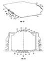
- FIG. 2is a rear perspective view of the vehicle of FIG. 1 with a rear hatch door removed for clarity;
- FIG. 3is a rear perspective of the vehicle of FIG. 1 including a tool box received by a tire disposed in a vehicle cargo space in accordance with an exemplary embodiment of the present invention
- FIG. 4is a rear perspective view of the rear cargo space of FIG. 3 in which a cover member is received by the tool box;
- FIG. 5is an exploded perspective view of the tool box assembly in accordance with an exemplary embodiment of the present invention.
- FIG. 7is a bottom perspective view of the tool box of FIG. 5 ;
- FIG. 8is a perspective view of the cover member of FIG. 5 ;
- FIG. 11is a perspective view of the cover member being located to the tool box of FIG. 5 ;
- FIG. 12is a perspective view of the cover member received by the tool box of FIG. 11 ;
- FIG. 13is a plan view of the installed tool box assembly of FIG. 2 with a carpet layer removed for clarity;
- a vehicle 10is illustrated in accordance with an exemplary embodiment of the present invention.
- the vehicle 10includes, among other features, a vehicle body structure 12 with a rear hatch opening 14 , a rear hatch door 16 , a rear cargo space 18 , a concave storage area 20 ( FIGS. 3 and 5 ) and a tool box assembly 22 ( FIG. 5 ).
- the rear hatch opening 14exposes the rear cargo space 18 with the rear hatch door 16 in an open orientation.
- the rear hatch door 16is shown in a closed orientation in FIG. 1 , but is completely removed from the vehicle 10 in FIG. 2 to provide a view of the rear cargo space 18 within the vehicle body structure 12 .
- the rear cargo space 18includes a deck 24 and the concave storage area 20 .
- the concave storage area 20has a curved wall portion 26 and a lower deck surface 28 below the deck 24 .
- the curved wall portion 26extends from the deck 24 to the lower deck surface 28 .
- the concave storage area 20is dimensioned to receive a spare tire 30 having an inner peripheral edge 31 , as shown in FIGS. 3, 5, 9, 14 and 15 . Because concave storage areas, such as spare tire storage areas, of vehicles are well known, further description is omitted for the sake of brevity.
- the tool box assembly 22is depicted in FIG. 5 in an unassembled state above the concave storage area 20 and the spare tire 30 .
- the tool box assembly 22is configured and dimensioned to overlay the spare tire 30 and be received within the concave storage area 20 , as shown in FIGS. 3, 9, 14 and 15 .
- the tool box assembly 22includes a tool box 40 and a cover member 42 received by the tool box 40 .
- the tool box assembly 22can further include a decorative covering or padded carpet, such as a carpet layer 32 , as shown in FIGS. 2, 5, 14 and 15 , to cover the concave storage area 20 and the cover member 42 .
- the tool box 40has a body 44 having a first end wall 46 and a second end wall 48 disposed opposite the first end wall 46 .
- An upper surface 50extends between upper ends of the first and second end walls 46 and 48 .
- a lower surface 52extends between lower ends of the first and second end walls 46 and 48 .
- the upper and lower surfaces 50 and 52are preferably substantially parallel.
- a first side wall 54extends between first sides of the first and second end walls 46 and 48 .
- a second side wall 56extends between second sides of the first and second end walls 46 and 48 .
- the first and second side walls 54 and 56are preferably substantially parallel.
- a length L from the first end wall 46 to the second end wall 48is preferably greater than a length W from the first side wall 54 to the second side wall 56 such that the tool box body 44 has a generally rectangular shape.
- the tool boxis configured to receive, retain and store a plurality of tools, such as a jack 34 , a lug-nut wrench 36 and a tow hook 38 , as shown in FIGS. 3 and 5 .
- a plurality of cut-outs 58 , 60 and 62are formed in the upper surface 50 of the tool box body 44 , as shown in FIG. 6 .
- the first cut-out 58receives the jack 34 .
- the second cut-out 60receives the lug-nut wrench 36 .
- the third cut-out 62receives the tow hook 38 . Any suitable number and shape of cut-outs can be formed in the tool box body 44 to receive appropriate tools for storage therein.
- the tool box 40is shown received by the spare tire 30 disposed in the storage area 20 .
- the first and second projections 72 and 74locate the tool box 40 to the spare tire 30 .
- the arcuate shapes of the first and second projections 72 and 74correspond to the inner peripheral edge 31 of the spare tire 30 to facilitate locating the tool box 40 to the spare tire 30 .
- the spare tire 30substantially prevents non-rotational movement of the tool box 40 .
- the plurality of first and second recesses 78 and 80reduces the surface area of the tool box body 44 contacting the spare tire 30 , thereby minimizing contact between the tool box body 44 and a side wall 33 of the spare tire 30 . By minimizing contact between the tool box 40 and the spare tire 30 , noises, such as squeaks or rattles, are minimized when the tool box 40 moves relative to the spare tire 30 .
- the first and second lips 64 and 66substantially prevent movement of the cover member 42 relative to the tool box 40 in addition to locating the cover member 42 to the tool box 40 .
- the cover member 42extends beyond the first and second side walls of the tool box 40 to substantially cover the storage area 20 , as shown in FIG. 4 .
- a lower surface 43 of the cover member 42is preferably resting on the upper surface 50 of the tool box body 44 .
- At least one recess 92is formed in the rear wall of the storage area 20 to facilitate gripping the cover member 42 such that the cover member 42 can be easily removed from tool box 40 in the storage area 20 , as shown in FIGS. 10 and 13 .
- first and second recesses 92 and 94are disposed on opposite sides of the storage area center line CL to allow the cover member 42 to be easily removed.
- the at least one recess 92is configured to allow a user to insert a finger therein and access the lower surface 43 of the cover member 42 to facilitate removal thereof.
- the term “comprising” and its derivatives, as used herein,are intended to be open ended terms that specify the presence of the stated features, elements, components, groups, integers, and/or steps, but do not exclude the presence of other unstated features, elements, components, groups, integers and/or steps.
- the foregoingalso applies to words having similar meanings such as the terms, “including”, “having” and their derivatives.
- the terms “part,” “section,” “portion,” “member” or “element” when used in the singularcan have the dual meaning of a single part or a plurality of parts.
Landscapes
- Engineering & Computer Science (AREA)
- Mechanical Engineering (AREA)
- Fittings On The Vehicle Exterior For Carrying Loads, And Devices For Holding Or Mounting Articles (AREA)
- Body Structure For Vehicles (AREA)
Abstract
Description
Claims (18)
Priority Applications (1)
| Application Number | Priority Date | Filing Date | Title |
|---|---|---|---|
| US14/669,594US9539957B2 (en) | 2015-03-26 | 2015-03-26 | Vehicle tool box assembly |
Applications Claiming Priority (1)
| Application Number | Priority Date | Filing Date | Title |
|---|---|---|---|
| US14/669,594US9539957B2 (en) | 2015-03-26 | 2015-03-26 | Vehicle tool box assembly |
Publications (2)
| Publication Number | Publication Date |
|---|---|
| US20160280151A1 US20160280151A1 (en) | 2016-09-29 |
| US9539957B2true US9539957B2 (en) | 2017-01-10 |
Family
ID=56973943
Family Applications (1)
| Application Number | Title | Priority Date | Filing Date |
|---|---|---|---|
| US14/669,594Expired - Fee RelatedUS9539957B2 (en) | 2015-03-26 | 2015-03-26 | Vehicle tool box assembly |
Country Status (1)
| Country | Link |
|---|---|
| US (1) | US9539957B2 (en) |
Cited By (6)
| Publication number | Priority date | Publication date | Assignee | Title |
|---|---|---|---|---|
| US20160368547A1 (en)* | 2015-06-22 | 2016-12-22 | C.R.F. Società Consortile Per Azioni | Motor-vehicle structure having a holding element for holding a spare wheel or other component on a floor portion made of plastic material |
| US10246020B1 (en) | 2017-12-14 | 2019-04-02 | Nissan North America, Inc. | Vehicle cargo area structure |
| US11021109B2 (en)* | 2018-11-14 | 2021-06-01 | GM Global Technology Operations LLC | Hidden storage compartment having a user notification system and method of using the same |
| US11260806B2 (en)* | 2019-12-16 | 2022-03-01 | Hyundai Motor Company | Tool case fixing structure of vehicle |
| US11299100B1 (en) | 2020-09-30 | 2022-04-12 | Ford Global Technologies, Llc | Vehicle including deployable fastener and tool carrier in cargo area |
| US20230065781A1 (en)* | 2021-08-25 | 2023-03-02 | Hyundai Motor Company | Wheel jack holder for vehicle |
Families Citing this family (9)
| Publication number | Priority date | Publication date | Assignee | Title |
|---|---|---|---|---|
| US10065579B2 (en)* | 2017-02-02 | 2018-09-04 | Ford Global Technologies, Llc | Scuff plate for cargo retention |
| US9932075B1 (en)* | 2017-03-30 | 2018-04-03 | Ford Global Technologies, Llc | Spare wheel assembly for a vehicle |
| DE102017208389B4 (en)* | 2017-05-18 | 2019-06-27 | Ford Global Technologies, Llc | Device box for the spare wheel well of a motor vehicle and motor vehicle with equipment box |
| DE102017111643A1 (en) | 2017-05-29 | 2018-11-29 | Bernd Rau | Platen for resting on and reinforcing an upper surface of a toolbox and use of such a platen |
| JP7231491B2 (en)* | 2019-06-11 | 2023-03-01 | 積水化成品工業株式会社 | tool box |
| FR3097521B1 (en) | 2019-06-24 | 2021-05-28 | Psa Automobiles Sa | MOTOR VEHICLE WITH PUNCTURED WHEEL REPAIR BOX SUPPORT |
| US11498489B2 (en)* | 2020-08-27 | 2022-11-15 | Honda Motor Co., Ltd. | Storage system for a vehicle and interior compartment of a vehicle having same |
| US11491925B2 (en)* | 2020-08-27 | 2022-11-08 | Honda Motor Co., Ltd. | Storage system for a vehicle and interior compartment of a vehicle having same |
| FR3120048B1 (en)* | 2021-02-19 | 2024-06-28 | Psa Automobiles Sa | Motor vehicle trunk bottom element |
Citations (17)
| Publication number | Priority date | Publication date | Assignee | Title |
|---|---|---|---|---|
| US1684699A (en)* | 1926-02-09 | 1928-09-18 | A D Leedy | Tire carrier and tool kit |
| US1715719A (en)* | 1929-06-04 | Combined tibe coves ahd tool box | ||
| US3513969A (en) | 1968-11-04 | 1970-05-26 | Jack H Roff | Bumper jack container assembly |
| US5429285A (en)* | 1993-09-09 | 1995-07-04 | Kim; Tae-Hyung | Receptacle adapted for car |
| US5586698A (en)* | 1994-05-30 | 1996-12-24 | Suzuki Motor Corporation | Automotive tool storage device |
| US5601206A (en)* | 1995-06-06 | 1997-02-11 | Rubbermaid Specialty Products, Inc. | Truck box |
| US5799845A (en)* | 1996-01-19 | 1998-09-01 | Suzuki Motor Corporation | Luggage compartment construction |
| US5855310A (en)* | 1997-02-18 | 1999-01-05 | Lear Corporation | Removable interior storage container for motor vehicle |
| US6026999A (en)* | 1998-02-20 | 2000-02-22 | Defs Inc. | Concentric tool box for motorized conveyances |
| US6336671B1 (en)* | 2000-11-15 | 2002-01-08 | Hugo Leonardi | Jack storage assembly |
| US20020053810A1 (en)* | 2000-03-09 | 2002-05-09 | Kaluszka Medard E | Tool retaining vehicle spare tire storage system |
| US6739742B2 (en) | 2002-02-21 | 2004-05-25 | Collins & Aikman Products Co. | Overhead storage apparatus for vehicles |
| US20050040191A1 (en)* | 2003-08-20 | 2005-02-24 | Honda Giken Kogyo Kabushiki Kaisha | Apparatus for compactly storing tools and accessories together with a spare wheel, and tool kit incorporating same |
| US7090274B1 (en) | 2005-02-11 | 2006-08-15 | Nissan Technical Center North America, Inc. | Vehicle storage structure |
| US20120121367A1 (en)* | 2003-06-18 | 2012-05-17 | Dura Global Technologies, Inc. | Spare tire handling device with a wheel retainer |
| US8808827B2 (en) | 2012-11-27 | 2014-08-19 | Global Ip Holdings, Llc | Cargo management system including a vehicle load floor having a vehicle component restraining feature |
| US20160090046A1 (en)* | 2014-09-30 | 2016-03-31 | Nissan North America, Inc. | Vehicle storage tray assembly |
- 2015
- 2015-03-26USUS14/669,594patent/US9539957B2/ennot_activeExpired - Fee Related
Patent Citations (17)
| Publication number | Priority date | Publication date | Assignee | Title |
|---|---|---|---|---|
| US1715719A (en)* | 1929-06-04 | Combined tibe coves ahd tool box | ||
| US1684699A (en)* | 1926-02-09 | 1928-09-18 | A D Leedy | Tire carrier and tool kit |
| US3513969A (en) | 1968-11-04 | 1970-05-26 | Jack H Roff | Bumper jack container assembly |
| US5429285A (en)* | 1993-09-09 | 1995-07-04 | Kim; Tae-Hyung | Receptacle adapted for car |
| US5586698A (en)* | 1994-05-30 | 1996-12-24 | Suzuki Motor Corporation | Automotive tool storage device |
| US5601206A (en)* | 1995-06-06 | 1997-02-11 | Rubbermaid Specialty Products, Inc. | Truck box |
| US5799845A (en)* | 1996-01-19 | 1998-09-01 | Suzuki Motor Corporation | Luggage compartment construction |
| US5855310A (en)* | 1997-02-18 | 1999-01-05 | Lear Corporation | Removable interior storage container for motor vehicle |
| US6026999A (en)* | 1998-02-20 | 2000-02-22 | Defs Inc. | Concentric tool box for motorized conveyances |
| US20020053810A1 (en)* | 2000-03-09 | 2002-05-09 | Kaluszka Medard E | Tool retaining vehicle spare tire storage system |
| US6336671B1 (en)* | 2000-11-15 | 2002-01-08 | Hugo Leonardi | Jack storage assembly |
| US6739742B2 (en) | 2002-02-21 | 2004-05-25 | Collins & Aikman Products Co. | Overhead storage apparatus for vehicles |
| US20120121367A1 (en)* | 2003-06-18 | 2012-05-17 | Dura Global Technologies, Inc. | Spare tire handling device with a wheel retainer |
| US20050040191A1 (en)* | 2003-08-20 | 2005-02-24 | Honda Giken Kogyo Kabushiki Kaisha | Apparatus for compactly storing tools and accessories together with a spare wheel, and tool kit incorporating same |
| US7090274B1 (en) | 2005-02-11 | 2006-08-15 | Nissan Technical Center North America, Inc. | Vehicle storage structure |
| US8808827B2 (en) | 2012-11-27 | 2014-08-19 | Global Ip Holdings, Llc | Cargo management system including a vehicle load floor having a vehicle component restraining feature |
| US20160090046A1 (en)* | 2014-09-30 | 2016-03-31 | Nissan North America, Inc. | Vehicle storage tray assembly |
Non-Patent Citations (1)
| Title |
|---|
| U.S. Appl. No. 14/502,266; Vehicle Storage Tray Assembly; E Engerman; filed Sep. 30, 2014. |
Cited By (8)
| Publication number | Priority date | Publication date | Assignee | Title |
|---|---|---|---|---|
| US20160368547A1 (en)* | 2015-06-22 | 2016-12-22 | C.R.F. Società Consortile Per Azioni | Motor-vehicle structure having a holding element for holding a spare wheel or other component on a floor portion made of plastic material |
| US9981702B2 (en)* | 2015-06-22 | 2018-05-29 | C.R.F. Societa Consortile Per Azioni | Motor vehicle structure having a holding element for holding a spare wheel or other component on a floor portion made of plastic material |
| US10246020B1 (en) | 2017-12-14 | 2019-04-02 | Nissan North America, Inc. | Vehicle cargo area structure |
| US11021109B2 (en)* | 2018-11-14 | 2021-06-01 | GM Global Technology Operations LLC | Hidden storage compartment having a user notification system and method of using the same |
| US11260806B2 (en)* | 2019-12-16 | 2022-03-01 | Hyundai Motor Company | Tool case fixing structure of vehicle |
| US11299100B1 (en) | 2020-09-30 | 2022-04-12 | Ford Global Technologies, Llc | Vehicle including deployable fastener and tool carrier in cargo area |
| US20230065781A1 (en)* | 2021-08-25 | 2023-03-02 | Hyundai Motor Company | Wheel jack holder for vehicle |
| US11820438B2 (en)* | 2021-08-25 | 2023-11-21 | Hyundai Motor Company | Wheel jack holder for vehicle |
Also Published As
| Publication number | Publication date |
|---|---|
| US20160280151A1 (en) | 2016-09-29 |
Similar Documents
| Publication | Publication Date | Title |
|---|---|---|
| US9539957B2 (en) | Vehicle tool box assembly | |
| USD867970S1 (en) | Car center console storage box | |
| US9457723B2 (en) | Vehicle storage tray assembly | |
| USD852717S1 (en) | Car storage compartment liner | |
| USD917373S1 (en) | Catalytic converter cover | |
| US9481240B1 (en) | Cover assembly for a filling port of a vehicle | |
| USD917374S1 (en) | Catalytic converter cover | |
| US20140070560A1 (en) | Cargo Area Protector With Hinged Outboard Flaps | |
| US20170088060A1 (en) | Vehicle center console assembly | |
| US9694754B2 (en) | Vehicle storage compartment assembly | |
| CN105480156B (en) | Baffle assembly reaches vehicle including this baffle assembly | |
| US20140152037A1 (en) | Suspended storage system for a vehicle glove box | |
| US10676005B2 (en) | Vehicle floor mat with storable barriers | |
| CN104838097A (en) | Oil pan for internal combustion engine | |
| JP4380023B2 (en) | Rear cargo compartment structure of vehicle | |
| US10434955B2 (en) | Luggage compartment structure of vehicle | |
| US10150397B2 (en) | Vehicle storage structure | |
| JP6052505B2 (en) | Vehicle luggage compartment structure | |
| JP5885774B2 (en) | Luggage tool box | |
| USD1066188S1 (en) | Vehicle side fairing | |
| JPH10297542A (en) | Car rear floor structure | |
| US9248770B2 (en) | Adaptable bin with rotating cup holder | |
| JP7302121B2 (en) | Vehicle luggage compartment structure | |
| JPH03276832A (en) | Console box | |
| JP2006036103A (en) | Luggage board |
Legal Events
| Date | Code | Title | Description |
|---|---|---|---|
| AS | Assignment | Owner name:NISSAN NORTH AMERICA, INC., TENNESSEE Free format text:ASSIGNMENT OF ASSIGNORS INTEREST;ASSIGNOR:ENGERMAN, ERIC;REEL/FRAME:035264/0794 Effective date:20150326 | |
| STCF | Information on status: patent grant | Free format text:PATENTED CASE | |
| AS | Assignment | Owner name:NISSAN MOTOR CO., LTD., JAPAN Free format text:ASSIGNMENT OF ASSIGNORS INTEREST;ASSIGNOR:NISSAN NORTH AMERICA, INC.;REEL/FRAME:042204/0071 Effective date:20170428 | |
| AS | Assignment | Owner name:NISSAN MOTOR CO., LTD., JAPAN Free format text:CORRECTIVE ASSIGNMENT TO CORRECT THE INCORRECT PATENT NO. 9598100 PREVIOUSLY RECORDED AT REEL: 042204 FRAME: 0071. ASSIGNOR(S) HEREBY CONFIRMS THE ASSIGNMENT;ASSIGNOR:NISSAN NORTH AMERICA, INC.;REEL/FRAME:042433/0624 Effective date:20170428 | |
| MAFP | Maintenance fee payment | Free format text:PAYMENT OF MAINTENANCE FEE, 4TH YEAR, LARGE ENTITY (ORIGINAL EVENT CODE: M1551); ENTITY STATUS OF PATENT OWNER: LARGE ENTITY Year of fee payment:4 | |
| FEPP | Fee payment procedure | Free format text:MAINTENANCE FEE REMINDER MAILED (ORIGINAL EVENT CODE: REM.); ENTITY STATUS OF PATENT OWNER: LARGE ENTITY | |
| LAPS | Lapse for failure to pay maintenance fees | Free format text:PATENT EXPIRED FOR FAILURE TO PAY MAINTENANCE FEES (ORIGINAL EVENT CODE: EXP.); ENTITY STATUS OF PATENT OWNER: LARGE ENTITY | |
| STCH | Information on status: patent discontinuation | Free format text:PATENT EXPIRED DUE TO NONPAYMENT OF MAINTENANCE FEES UNDER 37 CFR 1.362 | |
| FP | Lapsed due to failure to pay maintenance fee | Effective date:20250110 |