US9539084B2 - Devices and methods for tendon repair - Google Patents
Devices and methods for tendon repairDownload PDFInfo
- Publication number
- US9539084B2 US9539084B2US14/640,657US201514640657AUS9539084B2US 9539084 B2US9539084 B2US 9539084B2US 201514640657 AUS201514640657 AUS 201514640657AUS 9539084 B2US9539084 B2US 9539084B2
- Authority
- US
- United States
- Prior art keywords
- tendon
- repair device
- tendon repair
- implant
- needle
- Prior art date
- Legal status (The legal status is an assumption and is not a legal conclusion. Google has not performed a legal analysis and makes no representation as to the accuracy of the status listed.)
- Active
Links
- 210000002435tendonAnatomy0.000titleclaimsabstractdescription157
- 238000000034methodMethods0.000titleabstractdescription21
- 239000007943implantSubstances0.000claimsabstractdescription65
- 239000000463materialSubstances0.000claimsdescription25
- 239000004744fabricSubstances0.000claimsdescription14
- 230000003115biocidal effectEffects0.000claimsdescription7
- 230000002708enhancing effectEffects0.000claimsdescription6
- -1polypropylenePolymers0.000claimsdescription6
- 229920000742CottonPolymers0.000claimsdescription4
- 239000003242anti bacterial agentSubstances0.000claimsdescription4
- 239000002184metalSubstances0.000claimsdescription4
- SCRCZNMJAVGGEI-UHFFFAOYSA-N1,4-dioxane-2,5-dione;oxepan-2-oneChemical compoundO=C1COC(=O)CO1.O=C1CCCCCO1SCRCZNMJAVGGEI-UHFFFAOYSA-N0.000claimsdescription3
- 102000008186CollagenHuman genes0.000claimsdescription3
- 108010035532CollagenProteins0.000claimsdescription3
- 239000004677NylonSubstances0.000claimsdescription3
- 239000004743PolypropyleneSubstances0.000claimsdescription3
- 239000002253acidSubstances0.000claimsdescription3
- 229920001436collagenPolymers0.000claimsdescription3
- 229920001778nylonPolymers0.000claimsdescription3
- 229950010732poliglecaproneDrugs0.000claimsdescription3
- 229920000747poly(lactic acid)Polymers0.000claimsdescription3
- 229920002463poly(p-dioxanone) polymerPolymers0.000claimsdescription3
- 239000000622polydioxanoneSubstances0.000claimsdescription3
- 229920000728polyesterPolymers0.000claimsdescription3
- 239000004626polylactic acidSubstances0.000claimsdescription3
- 229920001155polypropylenePolymers0.000claimsdescription3
- PAPBSGBWRJIAAV-UHFFFAOYSA-Nε-CaprolactoneChemical compoundO=C1CCCCCO1PAPBSGBWRJIAAV-UHFFFAOYSA-N0.000claimsdescription3
- 239000003795chemical substances by applicationSubstances0.000claims5
- 241000894006BacteriaSpecies0.000claims2
- 239000007787solidSubstances0.000claims1
- 230000035876healingEffects0.000abstractdescription8
- 238000009958sewingMethods0.000abstractdescription2
- WYTGDNHDOZPMIW-RCBQFDQVSA-NalstonineNatural productsC1=CC2=C3C=CC=CC3=NC2=C2N1C[C@H]1[C@H](C)OC=C(C(=O)OC)[C@H]1C2WYTGDNHDOZPMIW-RCBQFDQVSA-N0.000description2
- 230000000975bioactive effectEffects0.000description2
- 239000000853adhesiveSubstances0.000description1
- 230000001070adhesive effectEffects0.000description1
- 229940088710antibiotic agentDrugs0.000description1
- 239000003814drugSubstances0.000description1
- 239000000122growth hormoneSubstances0.000description1
- 238000003780insertionMethods0.000description1
- 230000037431insertionEffects0.000description1
- 238000010297mechanical methods and processMethods0.000description1
- 239000011049pearlSubstances0.000description1
- 239000002831pharmacologic agentSubstances0.000description1
- 230000000717retained effectEffects0.000description1
- 239000000126substanceSubstances0.000description1
- 239000003356suture materialSubstances0.000description1
- 229920002994synthetic fiberPolymers0.000description1
- 239000012209synthetic fiberSubstances0.000description1
- 229940124597therapeutic agentDrugs0.000description1
Images


Classifications
- A—HUMAN NECESSITIES
- A61—MEDICAL OR VETERINARY SCIENCE; HYGIENE
- A61F—FILTERS IMPLANTABLE INTO BLOOD VESSELS; PROSTHESES; DEVICES PROVIDING PATENCY TO, OR PREVENTING COLLAPSING OF, TUBULAR STRUCTURES OF THE BODY, e.g. STENTS; ORTHOPAEDIC, NURSING OR CONTRACEPTIVE DEVICES; FOMENTATION; TREATMENT OR PROTECTION OF EYES OR EARS; BANDAGES, DRESSINGS OR ABSORBENT PADS; FIRST-AID KITS
- A61F2/00—Filters implantable into blood vessels; Prostheses, i.e. artificial substitutes or replacements for parts of the body; Appliances for connecting them with the body; Devices providing patency to, or preventing collapsing of, tubular structures of the body, e.g. stents
- A61F2/02—Prostheses implantable into the body
- A61F2/08—Muscles; Tendons; Ligaments
- A61F2/0811—Fixation devices for tendons or ligaments
- A—HUMAN NECESSITIES
- A61—MEDICAL OR VETERINARY SCIENCE; HYGIENE
- A61B—DIAGNOSIS; SURGERY; IDENTIFICATION
- A61B17/00—Surgical instruments, devices or methods
- A61B17/04—Surgical instruments, devices or methods for suturing wounds; Holders or packages for needles or suture materials
- A—HUMAN NECESSITIES
- A61—MEDICAL OR VETERINARY SCIENCE; HYGIENE
- A61B—DIAGNOSIS; SURGERY; IDENTIFICATION
- A61B17/00—Surgical instruments, devices or methods
- A61B17/04—Surgical instruments, devices or methods for suturing wounds; Holders or packages for needles or suture materials
- A61B17/06—Needles ; Sutures; Needle-suture combinations; Holders or packages for needles or suture materials
- A61B17/06066—Needles, e.g. needle tip configurations
- A—HUMAN NECESSITIES
- A61—MEDICAL OR VETERINARY SCIENCE; HYGIENE
- A61B—DIAGNOSIS; SURGERY; IDENTIFICATION
- A61B17/00—Surgical instruments, devices or methods
- A61B17/04—Surgical instruments, devices or methods for suturing wounds; Holders or packages for needles or suture materials
- A61B17/06—Needles ; Sutures; Needle-suture combinations; Holders or packages for needles or suture materials
- A61B17/06166—Sutures
- A—HUMAN NECESSITIES
- A61—MEDICAL OR VETERINARY SCIENCE; HYGIENE
- A61B—DIAGNOSIS; SURGERY; IDENTIFICATION
- A61B17/00—Surgical instruments, devices or methods
- A61B17/064—Surgical staples, i.e. penetrating the tissue
- A61B17/0643—Surgical staples, i.e. penetrating the tissue with separate closing member, e.g. for interlocking with staple
- A—HUMAN NECESSITIES
- A61—MEDICAL OR VETERINARY SCIENCE; HYGIENE
- A61B—DIAGNOSIS; SURGERY; IDENTIFICATION
- A61B17/00—Surgical instruments, devices or methods
- A61B17/11—Surgical instruments, devices or methods for performing anastomosis; Buttons for anastomosis
- A61B17/1146—Surgical instruments, devices or methods for performing anastomosis; Buttons for anastomosis of tendons
- A—HUMAN NECESSITIES
- A61—MEDICAL OR VETERINARY SCIENCE; HYGIENE
- A61B—DIAGNOSIS; SURGERY; IDENTIFICATION
- A61B17/00—Surgical instruments, devices or methods
- A61B17/12—Surgical instruments, devices or methods for ligaturing or otherwise compressing tubular parts of the body, e.g. blood vessels or umbilical cord
- A61B17/122—Clamps or clips, e.g. for the umbilical cord
- A—HUMAN NECESSITIES
- A61—MEDICAL OR VETERINARY SCIENCE; HYGIENE
- A61B—DIAGNOSIS; SURGERY; IDENTIFICATION
- A61B17/00—Surgical instruments, devices or methods
- A61B17/12—Surgical instruments, devices or methods for ligaturing or otherwise compressing tubular parts of the body, e.g. blood vessels or umbilical cord
- A61B17/128—Surgical instruments, devices or methods for ligaturing or otherwise compressing tubular parts of the body, e.g. blood vessels or umbilical cord for applying or removing clamps or clips
- A—HUMAN NECESSITIES
- A61—MEDICAL OR VETERINARY SCIENCE; HYGIENE
- A61F—FILTERS IMPLANTABLE INTO BLOOD VESSELS; PROSTHESES; DEVICES PROVIDING PATENCY TO, OR PREVENTING COLLAPSING OF, TUBULAR STRUCTURES OF THE BODY, e.g. STENTS; ORTHOPAEDIC, NURSING OR CONTRACEPTIVE DEVICES; FOMENTATION; TREATMENT OR PROTECTION OF EYES OR EARS; BANDAGES, DRESSINGS OR ABSORBENT PADS; FIRST-AID KITS
- A61F2/00—Filters implantable into blood vessels; Prostheses, i.e. artificial substitutes or replacements for parts of the body; Appliances for connecting them with the body; Devices providing patency to, or preventing collapsing of, tubular structures of the body, e.g. stents
- A61F2/02—Prostheses implantable into the body
- A61F2/08—Muscles; Tendons; Ligaments
- A—HUMAN NECESSITIES
- A61—MEDICAL OR VETERINARY SCIENCE; HYGIENE
- A61B—DIAGNOSIS; SURGERY; IDENTIFICATION
- A61B17/00—Surgical instruments, devices or methods
- A61B17/04—Surgical instruments, devices or methods for suturing wounds; Holders or packages for needles or suture materials
- A61B17/06—Needles ; Sutures; Needle-suture combinations; Holders or packages for needles or suture materials
- A61B2017/06057—Double-armed sutures, i.e. sutures having a needle attached to each end
- A—HUMAN NECESSITIES
- A61—MEDICAL OR VETERINARY SCIENCE; HYGIENE
- A61B—DIAGNOSIS; SURGERY; IDENTIFICATION
- A61B17/00—Surgical instruments, devices or methods
- A61B17/04—Surgical instruments, devices or methods for suturing wounds; Holders or packages for needles or suture materials
- A61B17/06—Needles ; Sutures; Needle-suture combinations; Holders or packages for needles or suture materials
- A61B17/06166—Sutures
- A61B2017/06176—Sutures with protrusions, e.g. barbs
- A—HUMAN NECESSITIES
- A61—MEDICAL OR VETERINARY SCIENCE; HYGIENE
- A61B—DIAGNOSIS; SURGERY; IDENTIFICATION
- A61B17/00—Surgical instruments, devices or methods
- A61B17/064—Surgical staples, i.e. penetrating the tissue
- A61B2017/0641—Surgical staples, i.e. penetrating the tissue having at least three legs as part of one single body
- A—HUMAN NECESSITIES
- A61—MEDICAL OR VETERINARY SCIENCE; HYGIENE
- A61B—DIAGNOSIS; SURGERY; IDENTIFICATION
- A61B17/00—Surgical instruments, devices or methods
- A61B17/064—Surgical staples, i.e. penetrating the tissue
- A61B2017/0647—Surgical staples, i.e. penetrating the tissue having one single leg, e.g. tacks
- A61B2017/0648—Surgical staples, i.e. penetrating the tissue having one single leg, e.g. tacks threaded, e.g. tacks with a screw thread
- A—HUMAN NECESSITIES
- A61—MEDICAL OR VETERINARY SCIENCE; HYGIENE
- A61F—FILTERS IMPLANTABLE INTO BLOOD VESSELS; PROSTHESES; DEVICES PROVIDING PATENCY TO, OR PREVENTING COLLAPSING OF, TUBULAR STRUCTURES OF THE BODY, e.g. STENTS; ORTHOPAEDIC, NURSING OR CONTRACEPTIVE DEVICES; FOMENTATION; TREATMENT OR PROTECTION OF EYES OR EARS; BANDAGES, DRESSINGS OR ABSORBENT PADS; FIRST-AID KITS
- A61F2/00—Filters implantable into blood vessels; Prostheses, i.e. artificial substitutes or replacements for parts of the body; Appliances for connecting them with the body; Devices providing patency to, or preventing collapsing of, tubular structures of the body, e.g. stents
- A61F2/02—Prostheses implantable into the body
- A61F2/08—Muscles; Tendons; Ligaments
- A61F2/0811—Fixation devices for tendons or ligaments
- A61F2002/0817—Structure of the anchor
- A—HUMAN NECESSITIES
- A61—MEDICAL OR VETERINARY SCIENCE; HYGIENE
- A61F—FILTERS IMPLANTABLE INTO BLOOD VESSELS; PROSTHESES; DEVICES PROVIDING PATENCY TO, OR PREVENTING COLLAPSING OF, TUBULAR STRUCTURES OF THE BODY, e.g. STENTS; ORTHOPAEDIC, NURSING OR CONTRACEPTIVE DEVICES; FOMENTATION; TREATMENT OR PROTECTION OF EYES OR EARS; BANDAGES, DRESSINGS OR ABSORBENT PADS; FIRST-AID KITS
- A61F2/00—Filters implantable into blood vessels; Prostheses, i.e. artificial substitutes or replacements for parts of the body; Appliances for connecting them with the body; Devices providing patency to, or preventing collapsing of, tubular structures of the body, e.g. stents
- A61F2/02—Prostheses implantable into the body
- A61F2/08—Muscles; Tendons; Ligaments
- A61F2/0811—Fixation devices for tendons or ligaments
- A61F2002/0847—Mode of fixation of anchor to tendon or ligament
- A61F2002/0858—Fixation of tendon or ligament between anchor and bone, e.g. interference screws, wedges
- A—HUMAN NECESSITIES
- A61—MEDICAL OR VETERINARY SCIENCE; HYGIENE
- A61F—FILTERS IMPLANTABLE INTO BLOOD VESSELS; PROSTHESES; DEVICES PROVIDING PATENCY TO, OR PREVENTING COLLAPSING OF, TUBULAR STRUCTURES OF THE BODY, e.g. STENTS; ORTHOPAEDIC, NURSING OR CONTRACEPTIVE DEVICES; FOMENTATION; TREATMENT OR PROTECTION OF EYES OR EARS; BANDAGES, DRESSINGS OR ABSORBENT PADS; FIRST-AID KITS
- A61F2/00—Filters implantable into blood vessels; Prostheses, i.e. artificial substitutes or replacements for parts of the body; Appliances for connecting them with the body; Devices providing patency to, or preventing collapsing of, tubular structures of the body, e.g. stents
- A61F2/02—Prostheses implantable into the body
- A61F2/08—Muscles; Tendons; Ligaments
- A61F2/0811—Fixation devices for tendons or ligaments
- A61F2002/0847—Mode of fixation of anchor to tendon or ligament
- A61F2002/087—Anchor integrated into tendons, e.g. bone blocks, integrated rings
- A—HUMAN NECESSITIES
- A61—MEDICAL OR VETERINARY SCIENCE; HYGIENE
- A61F—FILTERS IMPLANTABLE INTO BLOOD VESSELS; PROSTHESES; DEVICES PROVIDING PATENCY TO, OR PREVENTING COLLAPSING OF, TUBULAR STRUCTURES OF THE BODY, e.g. STENTS; ORTHOPAEDIC, NURSING OR CONTRACEPTIVE DEVICES; FOMENTATION; TREATMENT OR PROTECTION OF EYES OR EARS; BANDAGES, DRESSINGS OR ABSORBENT PADS; FIRST-AID KITS
- A61F2250/00—Special features of prostheses classified in groups A61F2/00 - A61F2/26 or A61F2/82 or A61F9/00 or A61F11/00 or subgroups thereof
- A61F2250/0058—Additional features; Implant or prostheses properties not otherwise provided for
- A61F2250/0067—Means for introducing or releasing pharmaceutical products into the body
Definitions
- the present inventionrelates to a device and method for repairing a ruptured tendon that reduces the likelihood of the tendon being partially or completely ruptured again while healing.
- a ruptureWhen a tendon is partially or totally ruptured or severed (collectively, “a rupture”), the two ends of the tendon where the rupture occurred are reattached surgically. In practice, this is accomplished by a surgeon stitching (i.e., suturing) the two ends together.
- the suturingcan be done in any suitable manner, as there have been many demonstrated techniques of suture repair.
- a problem with these standard suture techniquesis that the sutured tendon is relatively weak until the tendon is fully healed and the tendon can rupture if the force applied to the repaired tendon exceeds the strength of the repair.
- the inventioncomprises an implant placed inside or outside a ruptured tendon on both sides of the rupture in order to strengthen the tendon repair of the ruptured area during healing.
- the implant and tendonare secured together by sewing or stapling through the tendon and implant, or by any other suitable method (including staples, tacks or rivets) that utilizes the implant to provide strength to the ruptured area. In this manner the tendon can heal with less chance of rupturing again prior to healing.
- each end of the ruptured tendonmay be positioned inside a tube (or other type of external implant) and retained there in order for the tendon to heal.
- the material forming the external implantadds strength to the ruptured area to help prevent the tendon from rupturing again prior to healing.
- the tendon and external implantcan be secured together by any physical means, such as those as noted above.
- FIG. 1shows an embodiment of a device according to the invention.
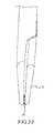
- FIGS. 2A-2Cshow an embodiment of a needle according to the invention.
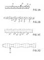
- FIG. 3A-3Dshow various implants having surface textures and material configurations according to aspects of the invention.
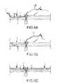
- FIG. 4depicts the first step in positioning a device according to the invention in a ruptured tendon.
- FIG. 5depicts a second step in positioning a device according to the invention in a ruptured tendon.
- FIGS. 6A-6Cdepicts a third step in positioning a device according to the invention in a ruptured tendon.
- FIG. 7depicts a fourth step in positioning a device according to the invention in a ruptured tendon.
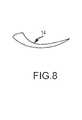
- FIG. 8depicts a needle according to the invention.
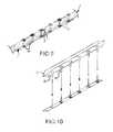
- FIG. 9shows an embodiment wherein needles or spikes are used to temporarily or permanently secure the ruptured area of a tendon in place.
- FIG. 10shows rivets that could be used to secure an insert in place in a tendon for repair.
- FIG. 11shows rivets of the type shown in FIG. 10 that could be used to secure an insert inside of or outside of a tendon.
- FIG. 12shows another type of fastener that may be used to secure an insert inside of or outside of a tendon.
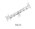
- FIG. 13shows a tendon that is first secured over spikes or needles and a knife that goes through the tendon to pull an insert through the tendon and the rupture.
- FIG. 14shows an insert according to an aspect of the invention that includes directional barbs that help prevent the insert from being dislodged from the tendon.
- FIG. 15shows an alternative shaped insert that may be used inside of a tendon.
- FIG. 16shows an insert that is positioned outside of the tendon.
- FIG. 17shows two cross-sectional views of inserts that may be positioned outside of a tendon.
- FIG. 17Ais a view of an embodiment of the insert of FIG. 16 laid out flat to show its interior surface.
- FIGS. 18-20show different embodiments of an insert that may be used inside of a tendon.
- FIGS. 21 and 22show a clamp and tool used to position and crimp the clamp that can be used to secure an insert according to the invention.
- FIG. 1shows a tendon repair device 10 according to an aspect of the invention.
- Device 10has a support implant 11 having a body portion 12 , with a first end 12 A and second end 12 B.
- the function of support implant 11is to be inserted into each end of a ruptured tendon 1 so as strengthen the repair to the rupture in order to help prevent the tendon from rupturing again prior to healing.
- the tendonhas a first end 2 and another, second end 4 . The two ends must be connected to repair the rupture.
- Implant 11can be formed of any suitable bio-absorbable or non-bio-absorbable material, and Implant may be a mesh like or cloth like, flexible material. Textured edges, scalloping or other physical characteristics may be present on implant 11 to increase its friction with the tendon to help prevent slippage.
- implant 11may have an outer surface having one of a: spiraled configuration, a cruciate cross section, and a plurality of outwardly-extending ribs.
- implant 11comprises standard suture material, which is either absorbable or nonabsorbable.
- standard suture materialincludes threads that may be monofilament or polyfilament braid or weave formed in approximately a 6 cm ⁇ 3 mm mesh.
- the insertmay be tubular, or generally flat, or of any suitable configuration.
- Exemplary embodiments of implants according to various aspects of the inventionmay include a fabric material.
- Such fabric materialmay be woven, knitted, braided, and/or twisted.
- the fabricmay comprise any desired combination of absorbable and non-absorbable materials, including silk, cotton, metal, and/or synthetic fibers.
- the fabricmay be of any suitable size, shape, thickness, and density.
- absorbable materialsexamples include polyglactin, polycaprolate, poliglecaprone, polysorb, polyglygolic acid, polylactic acid, polydioxanone, caprolactone, collagen, surgical gut, and combinations thereof.
- non-absorbable materialsexamples include polypropylene, polyester, nylon, silk, cotton, metal, and combinations thereof.
- the implant 11could also be pretreated with an antibiotic or growth enhancing substance.
- antibioticsthere are many commercially-available pharmacological agents such as antibiotics and therapeutic agents such as growth hormones and/or bioactive molecules that may accelerate tendon healing. Additionally, non-bioactive products may be incorporated into the implant to physically strengthen the repair.
- end 12 A and 12 Bare each attached to a separate needle 14 .
- Each needle 14is for being inserted into one of the ends of the ruptured tendon 1 and to pull body portion 12 of implant 11 into the first end 2 of the tendon and the second end 4 of the tendon, respectively.
- Any suitable needle or other devicemay be used for this purpose. It is preferred, however, that the needle have a shape that predetermines how far it penetrates along the length of each end of the tendon 1 .
- each needle 14has a relatively straight portion 14 A and a curved portion 14 B, as best seen in FIGS. 1 and 8 .
- Other devices for insertion of an insert 11could be used, such as reamers designed to open a path in the tendon for insert placement.
- the size and shape of needle 14is determined by the size and shape of the particular implant. In this current depiction, the dimensions of needle 14 are 2 cm in length and 3 mm wide at the portion to which the implant 11 is attached. The size and shape of needle 14 depends on the size of the tendon to be repaired and the type of implant used to support the ruptured area of the tendon. Different needle lengths and sizes may be required for different size tendons and different space requirements within the body.
- Implant 11has an outer surface 16 .
- Outer surface 16preferably has a surface that creates friction with the inner part of the tendon 1 , which outer surface 16 will contact when inserted into tendon 1 .
- the purpose of the frictionis to bind implant 11 with the tendon to help insure the two do not separate and thus to help strengthen the support provided by implant 11 at the rupture site.
- the outer surface 16 of implant 11may have any one of or combination of configurations to create friction.
- the outer surfaceincludes stiplets 18 .
- the stiplets 18are between 1 mm and 2 mm in height (as measured according to the distance from the main portion 16 A of the outer surface), and most preferably about 0.5-2 mm in height.
- the size of the stipletsmay vary, however, according to the size of the tendon and type of rupture being repaired.
- the stipletsmay be between 0.5 mm and 4 mm in height and between 0.5 mm and 4 mm in diameter at the base.
- each stiplet 18is between 0.5-5 mm in distance from the next closest stiplet 18 , although any suitable distance may be selected.
- the implantcould resemble a string of pearls (as shown in FIGS. 3B and 15 ) which would have relatively large variations between the larger stiplets and the smaller size of the implant between the stiplets.
- implant 11could have a co-figuration such as a stiplets on a tape strip or cord that might be, for example, 3 mm wide by 1 mm thick and have with stiplets on either or both sides, or have a top and/or bottom surface that is microtextured in any manner, and may simply be the surface of a coarse, braided cloth material.
- FIGS. 3B and 3Cshow implants that have ribbed outer surfaces.
- the diameter of the main portion 16 B of the outer surfaceis relatively narrow, and each rib 20 has a height of approximately 0.5 mm as measured from the main portion 16 B, although any suitable height may be utilized, such as between 1 mm-8 mm.
- each rib 22has a height of approximately 0.5 mm as measured from the main portion 16 C, although any suitable height may be utilized, such as between 1 mm-8 mm.
- FIG. 3Dshows an implant with a serpentine outer wall 16 D.
- the variation between the smallest diameter of the implant and the lowestis about 0.5 mm to about 4 mm, although any suitable dimensions, for example between 1 mm and 2 mm to 5 mm, or 2 mm and 3 mm to 5 mm, may be used.
- the implant 11could have a serpentine outer wall and also include stiplets and/or ribs.
- the implantmay include backward angled barbs that allow the implant to be pulled through the tendon, but that resist removal when pulled in a direction against the barbs, as shown in FIG. 14 .
- the two ends 2 and 4 of the tendon 1 and the implant 11are mechanically attached in any suitable manner, such as by suturing, stapling, or using surgical rivets or pins.
- FIGS. 4-7One method of effectuating a repair is shown in FIGS. 4-7 .
- FIG. 4shows ends 2 and 4 of ruptured tendon 1 being initially attached with a suture.
- FIG. 5shows a needle 14 with end 12 A of implant 11 attached thereto being pushed through first end 2 of tendon 1 . This pulls part of the body portion 12 into the first end 2 .
- the implant materialis cut away from the needle 14 , and preferably close to the outer surface of the tendon 1 .
- the ruptured ends on the tendon and the implantare mechanically attached. As shown in FIG. 7 , this is done using any of the known tendon suturing techniques. Any suitable technique, however, such as a suturing technique, stapling, or other mechanical method of attachment could be utilized. Adhesive might be used to augment the repair. In this manner, the implant adds significant strength to the rupture area and helps to prevent it from rupturing or pulling apart partially to create a gap under a load prior to healing.
- Implant 30is a hollow tube into which the first end 2 and second end 4 of the ruptured tendon 1 are placed so they touch, and are preferably pressed together. In this embodiment, there is an opening 31 along one side of insert 30 to make placement of insert 30 around tendon 1 simple.
- the implant 30has an inner surface 32 defining a cavity 34 that is dimensioned to receive each end 2 and 4 of ruptured tendon 1 .
- the tendon ends 2 and 4 , and the implant 30would then be mechanically attached with any of the prior mentioned suture techniques, staples, rivets, pins, clamps, or in any suitable manner.
- inner surface 32may include apparatus 36 that enables each end 2 and 4 of tendon 4 to be inserted into cavity 34 , and that tend to hold the ends of the tendon in place and resist the ends 2 and 4 from being removed from cavity 34 .
- inner surface 32could have structures 36 that are backward-facing ribs or barbs as shown in FIG. 17A , which could extend any suitable distance outward from inner surface 32 .
- Such structurescould, for example, extend between 0.5 mm to 2 mm from inner surface 32 .
- an implant placed on the outside of tendon 1may not have any openings, such as opening 31 , as shown in cross-sectional view 30 A.
- FIG. 9shows needles 40 that can be used to secure a tendon in place with ends 2 and 4 juxtaposed prior to or after an insert 11 or insert 30 has been placed in or on the tendon 1 and secured thereto.
- FIG. 10depicts staples or rivets 45 that are placed by a stapler 42 to secure a tendon and insert inside of or outside the tendon according to methods and structures of the invention.
- FIG. 11shows rivets 45 positioned through an outer insert 30 and through a tendon 1 to hold insert 30 and ruptured ends 2 and 4 in place.
- FIG. 12shows another type of rivet 46 that can be used to secure a ruptured tendon and insert in position.
- FIG. 13shows a method and structure by which a ruptured tendon 1 is secured on spikes 50 to hold it in place.
- a knife or needleis pushed through tendon 1 to pull insert 11 therethrough to strengthen the rupture area at ends 2 and 4 .
- the tendon 1 and insert 11are then mechanically secured using any of the techniques described herein.
- pins or spikesmay be used to secure a tendon in place prior to repair using several of the techniques described herein.
- FIGS. 14 and 15which have previously been described, show alternate embodiments of insert 11 that is positioned inside of tendon 1 to effectuate a rupture repair.
- FIGS. 18-20show alternate configurations of insert 11 that may be positioned inside of tendon 1 to effectuate a rupture repair. Any of these embodiments may include structures such as stiplets, ribs, barbs or textured surfaces to secure them inside of a tendon 1 .
- FIGS. 21-22show a clamp 60 according to the invention and a tool 70 that may be used to position and compress clamp 60 .
- Clamp 60 and tool 70are known to those skilled in the art.
Landscapes
- Health & Medical Sciences (AREA)
- Life Sciences & Earth Sciences (AREA)
- Surgery (AREA)
- Public Health (AREA)
- Veterinary Medicine (AREA)
- General Health & Medical Sciences (AREA)
- Engineering & Computer Science (AREA)
- Biomedical Technology (AREA)
- Heart & Thoracic Surgery (AREA)
- Animal Behavior & Ethology (AREA)
- Nuclear Medicine, Radiotherapy & Molecular Imaging (AREA)
- Medical Informatics (AREA)
- Molecular Biology (AREA)
- Vascular Medicine (AREA)
- Rheumatology (AREA)
- Orthopedic Medicine & Surgery (AREA)
- Transplantation (AREA)
- Oral & Maxillofacial Surgery (AREA)
- Cardiology (AREA)
- Rehabilitation Therapy (AREA)
- Reproductive Health (AREA)
- Prostheses (AREA)
- Surgical Instruments (AREA)
Abstract
Description
Claims (46)
Priority Applications (2)
| Application Number | Priority Date | Filing Date | Title |
|---|---|---|---|
| US14/640,657US9539084B2 (en) | 2012-01-23 | 2015-03-06 | Devices and methods for tendon repair |
| US15/297,698US20170035553A1 (en) | 2012-01-23 | 2016-10-19 | Devices and methods for tendon repair |
Applications Claiming Priority (4)
| Application Number | Priority Date | Filing Date | Title |
|---|---|---|---|
| US201261589526P | 2012-01-23 | 2012-01-23 | |
| US201213548060A | 2012-07-12 | 2012-07-12 | |
| US13/648,019US9017404B2 (en) | 2012-01-23 | 2012-10-09 | Devices and methods for tendon repair |
| US14/640,657US9539084B2 (en) | 2012-01-23 | 2015-03-06 | Devices and methods for tendon repair |
Related Parent Applications (2)
| Application Number | Title | Priority Date | Filing Date |
|---|---|---|---|
| US201213548060AContinuation | 2012-01-23 | 2012-07-12 | |
| US13/648,019ContinuationUS9017404B2 (en) | 2012-01-23 | 2012-10-09 | Devices and methods for tendon repair |
Related Child Applications (1)
| Application Number | Title | Priority Date | Filing Date |
|---|---|---|---|
| US15/297,698ContinuationUS20170035553A1 (en) | 2012-01-23 | 2016-10-19 | Devices and methods for tendon repair |
Publications (2)
| Publication Number | Publication Date |
|---|---|
| US20150182325A1 US20150182325A1 (en) | 2015-07-02 |
| US9539084B2true US9539084B2 (en) | 2017-01-10 |
Family
ID=49325780
Family Applications (4)
| Application Number | Title | Priority Date | Filing Date |
|---|---|---|---|
| US13/648,019Active2033-04-12US9017404B2 (en) | 2012-01-23 | 2012-10-09 | Devices and methods for tendon repair |
| US14/640,657ActiveUS9539084B2 (en) | 2012-01-23 | 2015-03-06 | Devices and methods for tendon repair |
| US14/641,024AbandonedUS20150173737A1 (en) | 2012-01-23 | 2015-03-06 | Method for tendon repair |
| US15/297,698AbandonedUS20170035553A1 (en) | 2012-01-23 | 2016-10-19 | Devices and methods for tendon repair |
Family Applications Before (1)
| Application Number | Title | Priority Date | Filing Date |
|---|---|---|---|
| US13/648,019Active2033-04-12US9017404B2 (en) | 2012-01-23 | 2012-10-09 | Devices and methods for tendon repair |
Family Applications After (2)
| Application Number | Title | Priority Date | Filing Date |
|---|---|---|---|
| US14/641,024AbandonedUS20150173737A1 (en) | 2012-01-23 | 2015-03-06 | Method for tendon repair |
| US15/297,698AbandonedUS20170035553A1 (en) | 2012-01-23 | 2016-10-19 | Devices and methods for tendon repair |
Country Status (1)
| Country | Link |
|---|---|
| US (4) | US9017404B2 (en) |
Cited By (12)
| Publication number | Priority date | Publication date | Assignee | Title |
|---|---|---|---|---|
| US20170035553A1 (en)* | 2012-01-23 | 2017-02-09 | Exsomed International IP, LLC | Devices and methods for tendon repair |
| US10098680B2 (en) | 2012-07-12 | 2018-10-16 | Exsomed Holding Company Llc | Metacarpal bone stabilization device |
| US10188161B2 (en) | 2014-01-06 | 2019-01-29 | Exsomed International IP, LLC | Gloves with sensory windows |
| US10194923B2 (en) | 2016-05-10 | 2019-02-05 | Exsomed International IP, LLC | Tool for percutaneous joint cartilage destruction and preparation for joint fusion |
| US10245091B2 (en) | 2015-12-30 | 2019-04-02 | Exsomed Holding Company, Llc | Dip fusion spike screw |
| US10441330B2 (en) | 2015-05-19 | 2019-10-15 | Exsomed Holding Company, Llc | Distal radius plate |
| US11147604B2 (en) | 2016-01-12 | 2021-10-19 | ExsoMed Corporation | Bone stabilization device |
| US11147681B2 (en) | 2017-09-05 | 2021-10-19 | ExsoMed Corporation | Small bone angled compression screw |
| US11191576B2 (en) | 2017-09-05 | 2021-12-07 | ExsoMed Corporation | Intramedullary threaded nail for radial cortical fixation |
| US11191645B2 (en) | 2017-09-05 | 2021-12-07 | ExsoMed Corporation | Small bone tapered compression screw |
| US11259849B2 (en) | 2013-10-02 | 2022-03-01 | ExsoMed Corporation | Full wrist fusion device |
| USD976402S1 (en) | 2021-06-10 | 2023-01-24 | Cilag Gmbh International | Bidirectional barbed suture |
Families Citing this family (10)
| Publication number | Priority date | Publication date | Assignee | Title |
|---|---|---|---|---|
| US9993332B2 (en) | 2014-07-09 | 2018-06-12 | Medos International Sarl | Systems and methods for ligament graft preparation |
| US10182808B2 (en) | 2015-04-23 | 2019-01-22 | DePuy Synthes Products, Inc. | Knotless suture anchor guide |
| US10383720B2 (en) | 2015-12-22 | 2019-08-20 | DePuy Synthes Products, Inc. | Graft preparation system |
| ES2817794T3 (en) | 2016-08-26 | 2021-04-08 | Paragon 28 Inc | Tendon retention device |
| US11045305B2 (en) | 2016-08-26 | 2021-06-29 | Paragon 28, Inc. | Soft tissue retention devices, instrumentation and related methods |
| CA3099263C (en) | 2018-05-04 | 2022-05-10 | Paragon 28, Inc. | Soft tissue retention device, instrumentation and related methods |
| IT201800006092A1 (en)* | 2018-06-06 | 2019-12-06 | MEDICAL-TYPE DEVICE FOR THE REPAIR OF AN INJURED TISSUE, IN PARTICULAR A TENDON OR A LIGAMENT, AND RELATED REPAIR METHOD | |
| US20240050219A1 (en)* | 2019-02-25 | 2024-02-15 | Washington University | Soft tissue-hard tissue interface fixation device |
| IT202000006967A1 (en) | 2020-04-02 | 2021-10-02 | Torino Politecnico | Device and assembly for the repair of soft tissues, such as tendons and ligaments |
| WO2023009831A1 (en)* | 2021-07-29 | 2023-02-02 | Ergosurgical Group Corp. | Systems and methods for suturing |
Citations (76)
| Publication number | Priority date | Publication date | Assignee | Title |
|---|---|---|---|---|
| US3717146A (en) | 1971-02-01 | 1973-02-20 | W Halloran | Threaded intramedullary compression and fixation device |
| GB2007099A (en) | 1977-11-02 | 1979-05-16 | Hamas R S | Total wrist prosthetic device |
| CH643131A5 (en) | 1981-08-03 | 1984-05-30 | Jaquet Orthopedie | Transcutaneous pin for fixation of a bone fragment or element |
| US4471777A (en) | 1983-03-30 | 1984-09-18 | Mccorkle Jr Charles E | Endocardial lead extraction apparatus and method |
| CH646858A5 (en) | 1980-11-20 | 1984-12-28 | S & T Marketing Ag | Forceps for holding a nerve tract |
| US4584722A (en) | 1982-05-24 | 1986-04-29 | Yeda Research And Development Co., Ltd. | Prosthetic tendon |
| GB2181356A (en) | 1985-10-15 | 1987-04-23 | Univ New Mexico | Surgical clip and tool therefor |
| US4781191A (en) | 1987-01-20 | 1988-11-01 | Thompson James S | Method for enabling atraumatic passage of a severed tendon through a tendon sheath |
| US4901717A (en) | 1987-01-05 | 1990-02-20 | Moore Robert R | Tendon leader |
| US4909789A (en) | 1986-03-28 | 1990-03-20 | Olympus Optical Co., Ltd. | Observation assisting forceps |
| US5312255A (en) | 1989-06-05 | 1994-05-17 | Ernst Bauer | Screw implant for a jawbone |
| EP0597223A1 (en) | 1992-10-09 | 1994-05-18 | United States Surgical Corporation | Surgical apparatus for removing fasteners |
| US5667510A (en) | 1995-08-03 | 1997-09-16 | Combs; C. Robert | Joint fixation system and method |
| WO1997033537A1 (en) | 1996-03-13 | 1997-09-18 | Bramlet Dale G | Arthroplasty joint assembly |
| US5690633A (en) | 1994-09-23 | 1997-11-25 | Smith & Nephew Richards, Inc. | Orthopedic fracture fixation device |
| US5853413A (en) | 1997-04-18 | 1998-12-29 | Bristol-Myers Squibb Company | Wrist fusion plate |
| US6187007B1 (en) | 1996-07-31 | 2001-02-13 | Synthes (Usa) | Device for attaching fractured hip-joint heads |
| US6221006B1 (en) | 1998-02-10 | 2001-04-24 | Artemis Medical Inc. | Entrapping apparatus and method for use |
| US6231319B1 (en)* | 1998-02-13 | 2001-05-15 | Matsushita Electric Industrial Co., Ltd. | Hermetic compressor |
| US6231413B1 (en)* | 1995-01-31 | 2001-05-15 | Canon Kabushiki Kaisha | Electron-emitting device as well as electron source and image-forming apparatus using such devices |
| US6306140B1 (en) | 2001-01-17 | 2001-10-23 | Synthes (Usa) | Bone screw |
| US20010049529A1 (en) | 1996-11-12 | 2001-12-06 | Cachia Victor V. | Bone fixation system |
| US20020045897A1 (en) | 2000-10-16 | 2002-04-18 | Dixon Robert A. | Method and apparatus utilizing interference fit screw shanks for nonmetallic spinal stabilization |
| US20020055749A1 (en)* | 1997-02-25 | 2002-05-09 | Philip Stuart Esnouf | Surgical aid for connective tissue grafting and method for employing same |
| US20020055747A1 (en) | 2000-11-09 | 2002-05-09 | Metamorphic Surgical Devices, Llc | Apparatus for capturing objects beyond an operative site utilizing a capture device delivered on a medical guide wire |
| US20020143337A1 (en) | 2000-02-01 | 2002-10-03 | Hand Innovations, Inc. | Fixation device for metaphyseal long bone fractures |
| US20020198527A1 (en) | 2001-06-21 | 2002-12-26 | Helmut Muckter | Implantable screw for stabilization of a joint or a bone fracture |
| US20030083661A1 (en) | 2000-02-01 | 2003-05-01 | Hand Innovations, Inc. | Intramedullary fixation device for metaphyseal long bone fractures and methods of using the same |
| US6592623B1 (en)* | 1999-08-31 | 2003-07-15 | Virginia Commonwealth University Intellectual Property Foundation | Engineered muscle |
| US6607530B1 (en) | 1999-05-10 | 2003-08-19 | Highgate Orthopedics, Inc. | Systems and methods for spinal fixation |
| EP1378205A1 (en) | 2002-07-05 | 2004-01-07 | Newdeal S.A. | Compression screw for osteosynthesis |
| US6808526B1 (en) | 1998-07-13 | 2004-10-26 | Sepitec Foundation | Osteosynthesis screw, especially for application by a translaminar vertebral screw |
| WO2004093700A1 (en) | 2003-04-23 | 2004-11-04 | Dugal Simon Stewart James | A fixation device and method of fixation |
| US20040260288A1 (en) | 2003-06-20 | 2004-12-23 | Means Robert Earl | Slipped capital femoral epiphysis fixation screw (SCFEFS) |
| US20050075642A1 (en) | 2001-12-19 | 2005-04-07 | Felt Jeffrey C. | Bone smoothing method and system |
| US20050107791A1 (en) | 2003-11-14 | 2005-05-19 | Manderson Easton L. | Intramedullary locked compression screw for stabiliziation and union of complex ankle and subtalar deformities |
| WO2005092226A1 (en) | 2004-03-26 | 2005-10-06 | Synthes Gmbh | Articulated bone screw |
| US7041106B1 (en) | 2001-06-15 | 2006-05-09 | Biomet, Inc. | Interphalangeal fusion pin |
| US20060129153A1 (en) | 2003-04-10 | 2006-06-15 | Kaj Klaue | Device for temporarily splinting toes |
| US20060195099A1 (en) | 2005-02-15 | 2006-08-31 | Apex Abc, Llc | Bone screw for positive locking but flexible engagement to a bone |
| WO2006105935A1 (en) | 2005-04-04 | 2006-10-12 | Zimmer Gmbh | Pedicle screw |
| US20070027547A1 (en) | 2003-06-27 | 2007-02-01 | Advanced Bio Surfaces, Inc. | System and method for ankle arthroplasty |
| US20070135816A1 (en) | 2005-11-21 | 2007-06-14 | Ist Innovative Shoulder Technology Ag | Bone anchor |
| WO2007081601A2 (en) | 2006-01-10 | 2007-07-19 | Southern Illinois University | Material retrieval device and method of using |
| WO2007109140A2 (en) | 2006-03-17 | 2007-09-27 | Nexa Orthopedics, Inc. | Bone screw with selectively securable washer |
| WO2008063156A2 (en) | 2006-10-26 | 2008-05-29 | Chestnut Medical Technologies, Inc. | Intracorporeal grasping device |
| DE102007003645A1 (en) | 2007-01-22 | 2008-07-24 | Somatex Medical Technologies Gmbh | Damaged bone structures i.e. vertebral body, treating instrument for use during e.g. osteoporosis treatment, has elongate opening enabling expansion of barrel surface during force exertion in proximal-axial direction on cylinder distal end |
| US20080249547A1 (en) | 2005-11-02 | 2008-10-09 | University Of Massachusetts | Tissue clamp |
| US20080249574A1 (en) | 2007-03-20 | 2008-10-09 | Mccombs Mary | Bone Screw System |
| US20100106254A1 (en) | 2008-10-23 | 2010-04-29 | Delsignore Jeanne L | Surgical implantable stabilizer sling for basal joint arthroplasty |
| US20100121136A1 (en) | 2008-06-08 | 2010-05-13 | Lloyd Champagne | Methods and apparatus for capturing and manipulating body parts |
| US20100130978A1 (en) | 2008-09-17 | 2010-05-27 | Skeletal Dynamics Llc | Intramedullary Arthrodesis Nail and Method of Use |
| US20100312286A1 (en) | 2007-10-30 | 2010-12-09 | Dell Oca Alberto A Fernandez | Variable Angle Locked Bone Plate |
| US20100324556A1 (en) | 2008-06-24 | 2010-12-23 | Jeff Tyber | Fixation system, an intramedullary fixation assembly and method of use |
| WO2010151589A1 (en) | 2009-06-23 | 2010-12-29 | Replication Medical, Inc. | Trapezium prosthesis |
| US20110130794A1 (en) | 2009-11-27 | 2011-06-02 | Rahul Vaidya | Method and Apparatus for Minimally Invasive Subcutaneous Treatment of Long Bone Fractures |
| US7988724B2 (en) | 2003-12-23 | 2011-08-02 | Sadra Medical, Inc. | Systems and methods for delivering a medical implant |
| US20120083847A1 (en) | 2010-10-05 | 2012-04-05 | Huebner Randall J | Fastener with serrated thread for attachment to a bone plate at a selectable angle |
| US20120221104A1 (en)* | 2009-09-11 | 2012-08-30 | Allergan, Inc. | Prosthetic device and method of manufacturing the same |
| US20120253464A1 (en)* | 2003-06-30 | 2012-10-04 | Depuy Mitek, Inc. | Scaffold for connective tissue repair |
| US20120253465A1 (en)* | 2011-03-31 | 2012-10-04 | Biomet Manufacturing Corp | Dual Tendon Bundle |
| US20130053961A1 (en)* | 2008-03-27 | 2013-02-28 | The Cleveland Clinic Foundation | Reinforced tissue graft |
| US20130060333A1 (en)* | 2011-09-01 | 2013-03-07 | Eduardo Gonzalez-Hernandez | Tendon crimp for passage into a bone tunnel and method for use thereof |
| EP2606843A1 (en) | 2011-12-22 | 2013-06-26 | Stryker Trauma SA | Wrist fusion plate |
| US20130261662A1 (en)* | 2005-05-04 | 2013-10-03 | Joerg Mayer | Joining element |
| US20130274879A1 (en) | 2012-01-23 | 2013-10-17 | Lloyd P. Champagne | Devices and methods for tendon repair |
| US8597337B2 (en) | 2008-02-14 | 2013-12-03 | Lloyd P. Champagne | Joint fusion device |
| WO2014011933A1 (en) | 2012-07-12 | 2014-01-16 | Exsomed Holding Company Llc | Metacarpal bone stabilization device |
| US20140067063A1 (en) | 2004-10-26 | 2014-03-06 | P Tech, Llc | Devices and methods for stabilizing tissue and implants |
| EP2713386A1 (en) | 2012-09-27 | 2014-04-02 | STMicroelectronics S.r.l. | Process for manufacturing semiconductor devices, such as super-barrier sbr rectifiers |
| US8864804B2 (en) | 2008-02-14 | 2014-10-21 | Lloyd P. Champagne | Bent dip fusion screw |
| US20150094724A1 (en) | 2013-10-02 | 2015-04-02 | Exsomed Holding Company Llc | Joint scrubber |
| US20150094777A1 (en) | 2013-10-02 | 2015-04-02 | Exsomed Holding Company Llc | Bone screw |
| US20150094722A1 (en) | 2013-10-02 | 2015-04-02 | Exsomed Holding Company Llc | Full wrist fusion device |
| WO2015050902A1 (en) | 2013-10-02 | 2015-04-09 | Exsomed Holding Company Llc | Carpal metacarpal support device |
| WO2015050896A1 (en) | 2013-10-02 | 2015-04-09 | Exsomed Holding Company Llc | Nerve coupler |
Family Cites Families (12)
| Publication number | Priority date | Publication date | Assignee | Title |
|---|---|---|---|---|
| US5061283A (en)* | 1987-10-30 | 1991-10-29 | Pfizer Hospital Products Group, Inc. | Method for tendon and ligament repair |
| US7611521B2 (en)* | 1996-09-13 | 2009-11-03 | Tendon Technology, Ltd. | Apparatus and methods for tendon or ligament repair |
| US6599310B2 (en)* | 2001-06-29 | 2003-07-29 | Quill Medical, Inc. | Suture method |
| US20030130735A1 (en)* | 2002-01-09 | 2003-07-10 | Roger Rogalski | Graft device and methods of use |
| US8361113B2 (en)* | 2006-02-03 | 2013-01-29 | Biomet Sports Medicine, Llc | Method and apparatus for coupling soft tissue to a bone |
| US8012174B2 (en)* | 2006-02-01 | 2011-09-06 | Arthrex, Inc. | Method for double row fixation of tendon to bone |
| US20090275945A1 (en)* | 2008-04-30 | 2009-11-05 | Exploramed Nc4, Inc. | Sheaths for extra-articular implantable systems |
| US9198750B2 (en)* | 2010-03-11 | 2015-12-01 | Rotation Medical, Inc. | Tendon repair implant and method of arthroscopic implantation |
| WO2013074909A1 (en)* | 2011-11-18 | 2013-05-23 | Zimmer, Inc. | Porous metal device for regenerating soft tissue-to-bone interface |
| US9186163B2 (en)* | 2012-06-04 | 2015-11-17 | Depuy Mitek, Llc | Methods and devices for forming bone tunnels |
| US9254187B2 (en)* | 2012-07-20 | 2016-02-09 | Anthony E. Sudekum | Terminal tissue attachment and repair device |
| US9427309B2 (en)* | 2012-07-30 | 2016-08-30 | Conextions, Inc. | Soft tissue repair devices, systems, and methods |
- 2012
- 2012-10-09USUS13/648,019patent/US9017404B2/enactiveActive
- 2015
- 2015-03-06USUS14/640,657patent/US9539084B2/enactiveActive
- 2015-03-06USUS14/641,024patent/US20150173737A1/ennot_activeAbandoned
- 2016
- 2016-10-19USUS15/297,698patent/US20170035553A1/ennot_activeAbandoned
Patent Citations (84)
| Publication number | Priority date | Publication date | Assignee | Title |
|---|---|---|---|---|
| US3717146A (en) | 1971-02-01 | 1973-02-20 | W Halloran | Threaded intramedullary compression and fixation device |
| GB2007099A (en) | 1977-11-02 | 1979-05-16 | Hamas R S | Total wrist prosthetic device |
| CH646858A5 (en) | 1980-11-20 | 1984-12-28 | S & T Marketing Ag | Forceps for holding a nerve tract |
| CH643131A5 (en) | 1981-08-03 | 1984-05-30 | Jaquet Orthopedie | Transcutaneous pin for fixation of a bone fragment or element |
| US4584722A (en) | 1982-05-24 | 1986-04-29 | Yeda Research And Development Co., Ltd. | Prosthetic tendon |
| US4471777A (en) | 1983-03-30 | 1984-09-18 | Mccorkle Jr Charles E | Endocardial lead extraction apparatus and method |
| GB2181356A (en) | 1985-10-15 | 1987-04-23 | Univ New Mexico | Surgical clip and tool therefor |
| US4909789A (en) | 1986-03-28 | 1990-03-20 | Olympus Optical Co., Ltd. | Observation assisting forceps |
| US4901717A (en) | 1987-01-05 | 1990-02-20 | Moore Robert R | Tendon leader |
| US4781191A (en) | 1987-01-20 | 1988-11-01 | Thompson James S | Method for enabling atraumatic passage of a severed tendon through a tendon sheath |
| US5312255A (en) | 1989-06-05 | 1994-05-17 | Ernst Bauer | Screw implant for a jawbone |
| EP0597223A1 (en) | 1992-10-09 | 1994-05-18 | United States Surgical Corporation | Surgical apparatus for removing fasteners |
| US5690633A (en) | 1994-09-23 | 1997-11-25 | Smith & Nephew Richards, Inc. | Orthopedic fracture fixation device |
| US6231413B1 (en)* | 1995-01-31 | 2001-05-15 | Canon Kabushiki Kaisha | Electron-emitting device as well as electron source and image-forming apparatus using such devices |
| US5667510A (en) | 1995-08-03 | 1997-09-16 | Combs; C. Robert | Joint fixation system and method |
| US6475242B1 (en) | 1996-03-13 | 2002-11-05 | Dale G. Bramlet | Arthroplasty joint assembly |
| WO1997033537A1 (en) | 1996-03-13 | 1997-09-18 | Bramlet Dale G | Arthroplasty joint assembly |
| US6187007B1 (en) | 1996-07-31 | 2001-02-13 | Synthes (Usa) | Device for attaching fractured hip-joint heads |
| US20010049529A1 (en) | 1996-11-12 | 2001-12-06 | Cachia Victor V. | Bone fixation system |
| US20020055749A1 (en)* | 1997-02-25 | 2002-05-09 | Philip Stuart Esnouf | Surgical aid for connective tissue grafting and method for employing same |
| US5853413A (en) | 1997-04-18 | 1998-12-29 | Bristol-Myers Squibb Company | Wrist fusion plate |
| US6221006B1 (en) | 1998-02-10 | 2001-04-24 | Artemis Medical Inc. | Entrapping apparatus and method for use |
| US6231319B1 (en)* | 1998-02-13 | 2001-05-15 | Matsushita Electric Industrial Co., Ltd. | Hermetic compressor |
| US6808526B1 (en) | 1998-07-13 | 2004-10-26 | Sepitec Foundation | Osteosynthesis screw, especially for application by a translaminar vertebral screw |
| US6607530B1 (en) | 1999-05-10 | 2003-08-19 | Highgate Orthopedics, Inc. | Systems and methods for spinal fixation |
| US6592623B1 (en)* | 1999-08-31 | 2003-07-15 | Virginia Commonwealth University Intellectual Property Foundation | Engineered muscle |
| US20020143337A1 (en) | 2000-02-01 | 2002-10-03 | Hand Innovations, Inc. | Fixation device for metaphyseal long bone fractures |
| US20030083661A1 (en) | 2000-02-01 | 2003-05-01 | Hand Innovations, Inc. | Intramedullary fixation device for metaphyseal long bone fractures and methods of using the same |
| US20020045897A1 (en) | 2000-10-16 | 2002-04-18 | Dixon Robert A. | Method and apparatus utilizing interference fit screw shanks for nonmetallic spinal stabilization |
| US20020055747A1 (en) | 2000-11-09 | 2002-05-09 | Metamorphic Surgical Devices, Llc | Apparatus for capturing objects beyond an operative site utilizing a capture device delivered on a medical guide wire |
| US6306140B1 (en) | 2001-01-17 | 2001-10-23 | Synthes (Usa) | Bone screw |
| US7041106B1 (en) | 2001-06-15 | 2006-05-09 | Biomet, Inc. | Interphalangeal fusion pin |
| US20020198527A1 (en) | 2001-06-21 | 2002-12-26 | Helmut Muckter | Implantable screw for stabilization of a joint or a bone fracture |
| US20050075642A1 (en) | 2001-12-19 | 2005-04-07 | Felt Jeffrey C. | Bone smoothing method and system |
| EP1378205A1 (en) | 2002-07-05 | 2004-01-07 | Newdeal S.A. | Compression screw for osteosynthesis |
| US20060129153A1 (en) | 2003-04-10 | 2006-06-15 | Kaj Klaue | Device for temporarily splinting toes |
| WO2004093700A1 (en) | 2003-04-23 | 2004-11-04 | Dugal Simon Stewart James | A fixation device and method of fixation |
| US20040260288A1 (en) | 2003-06-20 | 2004-12-23 | Means Robert Earl | Slipped capital femoral epiphysis fixation screw (SCFEFS) |
| US20070027547A1 (en) | 2003-06-27 | 2007-02-01 | Advanced Bio Surfaces, Inc. | System and method for ankle arthroplasty |
| US20120253464A1 (en)* | 2003-06-30 | 2012-10-04 | Depuy Mitek, Inc. | Scaffold for connective tissue repair |
| US20050107791A1 (en) | 2003-11-14 | 2005-05-19 | Manderson Easton L. | Intramedullary locked compression screw for stabiliziation and union of complex ankle and subtalar deformities |
| US7988724B2 (en) | 2003-12-23 | 2011-08-02 | Sadra Medical, Inc. | Systems and methods for delivering a medical implant |
| WO2005092226A1 (en) | 2004-03-26 | 2005-10-06 | Synthes Gmbh | Articulated bone screw |
| US20070282342A1 (en) | 2004-03-26 | 2007-12-06 | Alfred Niederberger | Articulated Bone Screw |
| US20140067063A1 (en) | 2004-10-26 | 2014-03-06 | P Tech, Llc | Devices and methods for stabilizing tissue and implants |
| US20060195099A1 (en) | 2005-02-15 | 2006-08-31 | Apex Abc, Llc | Bone screw for positive locking but flexible engagement to a bone |
| WO2006105935A1 (en) | 2005-04-04 | 2006-10-12 | Zimmer Gmbh | Pedicle screw |
| US20090062868A1 (en) | 2005-04-04 | 2009-03-05 | Zimmer Gmbh | Pedicle screw |
| US20130261662A1 (en)* | 2005-05-04 | 2013-10-03 | Joerg Mayer | Joining element |
| US20080249547A1 (en) | 2005-11-02 | 2008-10-09 | University Of Massachusetts | Tissue clamp |
| US20070135816A1 (en) | 2005-11-21 | 2007-06-14 | Ist Innovative Shoulder Technology Ag | Bone anchor |
| WO2007081601A2 (en) | 2006-01-10 | 2007-07-19 | Southern Illinois University | Material retrieval device and method of using |
| WO2007109140A2 (en) | 2006-03-17 | 2007-09-27 | Nexa Orthopedics, Inc. | Bone screw with selectively securable washer |
| WO2008063156A2 (en) | 2006-10-26 | 2008-05-29 | Chestnut Medical Technologies, Inc. | Intracorporeal grasping device |
| DE102007003645A1 (en) | 2007-01-22 | 2008-07-24 | Somatex Medical Technologies Gmbh | Damaged bone structures i.e. vertebral body, treating instrument for use during e.g. osteoporosis treatment, has elongate opening enabling expansion of barrel surface during force exertion in proximal-axial direction on cylinder distal end |
| US20080249574A1 (en) | 2007-03-20 | 2008-10-09 | Mccombs Mary | Bone Screw System |
| US20100312286A1 (en) | 2007-10-30 | 2010-12-09 | Dell Oca Alberto A Fernandez | Variable Angle Locked Bone Plate |
| US8597337B2 (en) | 2008-02-14 | 2013-12-03 | Lloyd P. Champagne | Joint fusion device |
| US8864804B2 (en) | 2008-02-14 | 2014-10-21 | Lloyd P. Champagne | Bent dip fusion screw |
| US20130053961A1 (en)* | 2008-03-27 | 2013-02-28 | The Cleveland Clinic Foundation | Reinforced tissue graft |
| US20100121136A1 (en) | 2008-06-08 | 2010-05-13 | Lloyd Champagne | Methods and apparatus for capturing and manipulating body parts |
| US20100324556A1 (en) | 2008-06-24 | 2010-12-23 | Jeff Tyber | Fixation system, an intramedullary fixation assembly and method of use |
| US20100130978A1 (en) | 2008-09-17 | 2010-05-27 | Skeletal Dynamics Llc | Intramedullary Arthrodesis Nail and Method of Use |
| US20100106254A1 (en) | 2008-10-23 | 2010-04-29 | Delsignore Jeanne L | Surgical implantable stabilizer sling for basal joint arthroplasty |
| WO2010151589A1 (en) | 2009-06-23 | 2010-12-29 | Replication Medical, Inc. | Trapezium prosthesis |
| US20120221104A1 (en)* | 2009-09-11 | 2012-08-30 | Allergan, Inc. | Prosthetic device and method of manufacturing the same |
| US20110130794A1 (en) | 2009-11-27 | 2011-06-02 | Rahul Vaidya | Method and Apparatus for Minimally Invasive Subcutaneous Treatment of Long Bone Fractures |
| US20120083847A1 (en) | 2010-10-05 | 2012-04-05 | Huebner Randall J | Fastener with serrated thread for attachment to a bone plate at a selectable angle |
| US20120253465A1 (en)* | 2011-03-31 | 2012-10-04 | Biomet Manufacturing Corp | Dual Tendon Bundle |
| US20130060333A1 (en)* | 2011-09-01 | 2013-03-07 | Eduardo Gonzalez-Hernandez | Tendon crimp for passage into a bone tunnel and method for use thereof |
| US20130165979A1 (en) | 2011-12-22 | 2013-06-27 | Stryker Trauma Sa | Wrist fusion plate |
| EP2606843A1 (en) | 2011-12-22 | 2013-06-26 | Stryker Trauma SA | Wrist fusion plate |
| US20130274879A1 (en) | 2012-01-23 | 2013-10-17 | Lloyd P. Champagne | Devices and methods for tendon repair |
| US20150173737A1 (en)* | 2012-01-23 | 2015-06-25 | Exsomed International IP, LLC | Method for tendon repair |
| US9017404B2 (en)* | 2012-01-23 | 2015-04-28 | Lloyd P. Champagne | Devices and methods for tendon repair |
| WO2014011933A1 (en) | 2012-07-12 | 2014-01-16 | Exsomed Holding Company Llc | Metacarpal bone stabilization device |
| EP2713386A1 (en) | 2012-09-27 | 2014-04-02 | STMicroelectronics S.r.l. | Process for manufacturing semiconductor devices, such as super-barrier sbr rectifiers |
| US20150094722A1 (en) | 2013-10-02 | 2015-04-02 | Exsomed Holding Company Llc | Full wrist fusion device |
| WO2015050895A1 (en) | 2013-10-02 | 2015-04-09 | Exsomed Holding Company Llc | Full wrist fusion device |
| WO2015050898A1 (en) | 2013-10-02 | 2015-04-09 | Exsomed Holding Company Llc | Joint scrubber |
| WO2015050902A1 (en) | 2013-10-02 | 2015-04-09 | Exsomed Holding Company Llc | Carpal metacarpal support device |
| WO2015050896A1 (en) | 2013-10-02 | 2015-04-09 | Exsomed Holding Company Llc | Nerve coupler |
| US20150094777A1 (en) | 2013-10-02 | 2015-04-02 | Exsomed Holding Company Llc | Bone screw |
| US20150094724A1 (en) | 2013-10-02 | 2015-04-02 | Exsomed Holding Company Llc | Joint scrubber |
Non-Patent Citations (23)
| Title |
|---|
| EP; Examination Report dated May 25, 2012 in Application No. EP 09774002.1. |
| EP; Examination Report dated May 30, 2011 in Application No. EP 09774002.1. |
| PCT; International Search Report and Written Opinion dated Dec. 10, 2014 in Application No. PCT/US2014/058463. |
| PCT; International Search Report and Written Opinion dated Dec. 12, 2014 in Application No. PCT/US2014/058474. |
| PCT; International Search Report and Written Opinion dated Feb. 9, 2015 in Application No. PCT/US2014/058441. |
| PCT; International Search Report and Written Opinion dated Jan. 20, 2015 in Application No. PCT/US2014/058448. |
| PCT; International Search Report and Written Opinion dated Sep. 17, 2010 in Application No. PCT/US2009/046662. |
| PCT; International Search Report and Written Opinion dated Sep. 9, 2013 in Application No. PCT/US2013/050155. |
| USPTO; Final Office Action dated May 2, 2016 in U.S. Appl. No. 14/503,228. |
| USPTO; Final Office Action dated May 23, 2016 in U.S. Appl. No. 14/640,657. |
| USPTO; Notice of Allowance dated Dec. 31, 2014 in U.S. Appl. No. 13/648,019. |
| USPTO; Notice of Allowance dated Jul. 30, 2013 in U.S. Appl. No. 12/372,712. |
| USPTO; Notice of Allowance dated Jun. 25, 2014 in U.S. Appl. No. 13/555,933. |
| USPTO; Office Action dated Aug. 29, 2014 in U.S. Appl. No. 13/648,019. |
| USPTO; Office Action dated Feb. 18, 2014 in U.S. Appl. No. 13/555,933. |
| USPTO; Office Action dated Mar. 21, 2012 in U.S. Appl. No. 12/480,676. |
| USPTO; Office Action dated Mar. 22, 2013 in U.S. Appl. No. 12/372,712. |
| USPTO; Office Action dated May 29, 2012 in U.S. Appl. No. 12/372,712. |
| USPTO; Office Action dated Oct. 4, 2011 in U.S. Appl. No. 12/372,712. |
| USPTO; Office Action dated Oct. 5, 2015 in U.S. Appl. No. 13/940,173. |
| USPTO; Office Action dated Sep. 18, 2012 in U.S. Appl. No. 12/480,676. |
| USPTO; Office Action dated Sep. 22, 2015 in U.S. Appl. No. 14/503,228. |
| USPTO; Office Action dated Sep. 24, 2013 in U.S. Appl. No. 12/480,676. |
Cited By (19)
| Publication number | Priority date | Publication date | Assignee | Title |
|---|---|---|---|---|
| US20170035553A1 (en)* | 2012-01-23 | 2017-02-09 | Exsomed International IP, LLC | Devices and methods for tendon repair |
| US10098680B2 (en) | 2012-07-12 | 2018-10-16 | Exsomed Holding Company Llc | Metacarpal bone stabilization device |
| US12232785B2 (en) | 2013-10-02 | 2025-02-25 | ExsoMed Corporation | Full wrist fusion device |
| US11272965B2 (en) | 2013-10-02 | 2022-03-15 | ExsoMed Corporation | Full wrist fusion device |
| US11259849B2 (en) | 2013-10-02 | 2022-03-01 | ExsoMed Corporation | Full wrist fusion device |
| US10188161B2 (en) | 2014-01-06 | 2019-01-29 | Exsomed International IP, LLC | Gloves with sensory windows |
| US10925336B2 (en) | 2014-01-06 | 2021-02-23 | ExsoMed Corporation | Gloves with sensory windows |
| US11185357B2 (en) | 2015-05-19 | 2021-11-30 | ExsoMed Corporation | Distal radius plate |
| US10441330B2 (en) | 2015-05-19 | 2019-10-15 | Exsomed Holding Company, Llc | Distal radius plate |
| US10245091B2 (en) | 2015-12-30 | 2019-04-02 | Exsomed Holding Company, Llc | Dip fusion spike screw |
| US11147604B2 (en) | 2016-01-12 | 2021-10-19 | ExsoMed Corporation | Bone stabilization device |
| US10194923B2 (en) | 2016-05-10 | 2019-02-05 | Exsomed International IP, LLC | Tool for percutaneous joint cartilage destruction and preparation for joint fusion |
| US11191576B2 (en) | 2017-09-05 | 2021-12-07 | ExsoMed Corporation | Intramedullary threaded nail for radial cortical fixation |
| US11191645B2 (en) | 2017-09-05 | 2021-12-07 | ExsoMed Corporation | Small bone tapered compression screw |
| US11147681B2 (en) | 2017-09-05 | 2021-10-19 | ExsoMed Corporation | Small bone angled compression screw |
| US12042191B2 (en) | 2017-09-05 | 2024-07-23 | ExsoMed Corporation | Intramedullary threaded nail for radial cortical fixation |
| US12048464B2 (en) | 2017-09-05 | 2024-07-30 | ExsoMed Corporation | Intramedullary threaded nail for radial cortical fixation |
| US12251316B2 (en) | 2017-09-05 | 2025-03-18 | ExsoMed Corporation | Small bone angled compression screw |
| USD976402S1 (en) | 2021-06-10 | 2023-01-24 | Cilag Gmbh International | Bidirectional barbed suture |
Also Published As
| Publication number | Publication date |
|---|---|
| US20150182325A1 (en) | 2015-07-02 |
| US20170035553A1 (en) | 2017-02-09 |
| US9017404B2 (en) | 2015-04-28 |
| US20150173737A1 (en) | 2015-06-25 |
| US20130274879A1 (en) | 2013-10-17 |
Similar Documents
| Publication | Publication Date | Title |
|---|---|---|
| US9539084B2 (en) | Devices and methods for tendon repair | |
| US10905409B2 (en) | Tissue repair assembly | |
| JP6685883B2 (en) | Tissue repair | |
| AU2010286764B2 (en) | Barbed sutures having pledget stoppers and methods therefor | |
| US7967841B2 (en) | Methods for using looped tissue-grasping devices | |
| US7021316B2 (en) | Device and method for tacking a prosthetic screen | |
| JP4392239B2 (en) | Suture device | |
| JP7467464B2 (en) | Fixtures, assemblies, and related systems and methods | |
| US9539004B2 (en) | Collapsible locking suture | |
| WO2002053011A2 (en) | Suturing system | |
| JP7337490B2 (en) | Devices and methods for tissue repair | |
| JP7381627B2 (en) | Multi-density full suture anchor | |
| US20140296887A1 (en) | Tissue device | |
| JP2009261934A (en) | Apparatus for joining of tissue having integral penetrating end | |
| JP2024510793A (en) | Device to facilitate implantation of surgical mesh | |
| JP2012165880A (en) | Suturing device | |
| HK40005110A (en) | Indirect attachment of a needle to a mesh suture |
Legal Events
| Date | Code | Title | Description |
|---|---|---|---|
| STCF | Information on status: patent grant | Free format text:PATENTED CASE | |
| AS | Assignment | Owner name:ASIATRUST LTD., TRUSTEE OF THE QUATRO TRUST, COOK ISLANDS Free format text:ASSIGNMENT OF ASSIGNORS INTEREST;ASSIGNOR:EXSOMED INTERNATIONAL IP, LLC;REEL/FRAME:048037/0172 Effective date:20181218 Owner name:EXSOMED INTERNATIONAL, LLC, SAINT KITTS AND NEVIS Free format text:ASSIGNMENT OF ASSIGNORS INTEREST;ASSIGNOR:ASIATRUST LTD., TRUSTEE OF THE QUATRO TRUST;REEL/FRAME:048037/0318 Effective date:20181218 Owner name:ASIATRUST LTD., TRUSTEE OF THE QUATRO TRUST, COOK Free format text:ASSIGNMENT OF ASSIGNORS INTEREST;ASSIGNOR:EXSOMED INTERNATIONAL IP, LLC;REEL/FRAME:048037/0172 Effective date:20181218 Owner name:EXSOMED HOLDING COMPANY, LLC, ARIZONA Free format text:ASSIGNMENT OF ASSIGNORS INTEREST;ASSIGNOR:EXSOMED INTERNATIONAL, LLC;REEL/FRAME:048037/0747 Effective date:20181218 | |
| MAFP | Maintenance fee payment | Free format text:PAYMENT OF MAINTENANCE FEE, 4TH YR, SMALL ENTITY (ORIGINAL EVENT CODE: M2551); ENTITY STATUS OF PATENT OWNER: SMALL ENTITY Year of fee payment:4 | |
| AS | Assignment | Owner name:EXSOMED CORPORATION, CALIFORNIA Free format text:ASSIGNMENT OF ASSIGNORS INTEREST;ASSIGNOR:ZOLDOS, JOZEF;REEL/FRAME:059713/0558 Effective date:20220425 | |
| AS | Assignment | Owner name:EXSOMED CORPORATION, CALIFORNIA Free format text:ASSIGNMENT OF ASSIGNORS INTEREST;ASSIGNOR:CHAMPAGNE, LLOYD P.;REEL/FRAME:059785/0641 Effective date:20220429 | |
| AS | Assignment | Owner name:EXSOMED CORPORATION, CALIFORNIA Free format text:ASSIGNMENT OF ASSIGNORS INTEREST;ASSIGNOR:EXSOMED HOLDING COMPANY, LLC;REEL/FRAME:060051/0216 Effective date:20220429 | |
| FEPP | Fee payment procedure | Free format text:ENTITY STATUS SET TO UNDISCOUNTED (ORIGINAL EVENT CODE: BIG.); ENTITY STATUS OF PATENT OWNER: LARGE ENTITY |