US9537345B2 - Wireless charger and charging method - Google Patents
Wireless charger and charging methodDownload PDFInfo
- Publication number
- US9537345B2 US9537345B2US14/192,741US201414192741AUS9537345B2US 9537345 B2US9537345 B2US 9537345B2US 201414192741 AUS201414192741 AUS 201414192741AUS 9537345 B2US9537345 B2US 9537345B2
- Authority
- US
- United States
- Prior art keywords
- electronic device
- switch
- conversion unit
- electricity
- voltage
- Prior art date
- Legal status (The legal status is an assumption and is not a legal conclusion. Google has not performed a legal analysis and makes no representation as to the accuracy of the status listed.)
- Expired - Fee Related, expires
Links
- 238000000034methodMethods0.000titleclaimsdescription19
- 230000005611electricityEffects0.000claimsabstractdescription49
- 238000006243chemical reactionMethods0.000claimsdescription63
- 230000006698inductionEffects0.000claimsdescription6
- 238000010586diagramMethods0.000description2
- 238000013459approachMethods0.000description1
- 238000005516engineering processMethods0.000description1
- 238000012986modificationMethods0.000description1
- 230000004048modificationEffects0.000description1
Images


Classifications
- H02J7/025—
- H—ELECTRICITY
- H02—GENERATION; CONVERSION OR DISTRIBUTION OF ELECTRIC POWER
- H02J—CIRCUIT ARRANGEMENTS OR SYSTEMS FOR SUPPLYING OR DISTRIBUTING ELECTRIC POWER; SYSTEMS FOR STORING ELECTRIC ENERGY
- H02J7/00—Circuit arrangements for charging or depolarising batteries or for supplying loads from batteries
- H02J7/02—Circuit arrangements for charging or depolarising batteries or for supplying loads from batteries for charging batteries from AC mains by converters
- H02J17/00—
- H—ELECTRICITY
- H02—GENERATION; CONVERSION OR DISTRIBUTION OF ELECTRIC POWER
- H02J—CIRCUIT ARRANGEMENTS OR SYSTEMS FOR SUPPLYING OR DISTRIBUTING ELECTRIC POWER; SYSTEMS FOR STORING ELECTRIC ENERGY
- H02J50/00—Circuit arrangements or systems for wireless supply or distribution of electric power
- H02J50/10—Circuit arrangements or systems for wireless supply or distribution of electric power using inductive coupling
- H—ELECTRICITY
- H02—GENERATION; CONVERSION OR DISTRIBUTION OF ELECTRIC POWER
- H02J—CIRCUIT ARRANGEMENTS OR SYSTEMS FOR SUPPLYING OR DISTRIBUTING ELECTRIC POWER; SYSTEMS FOR STORING ELECTRIC ENERGY
- H02J50/00—Circuit arrangements or systems for wireless supply or distribution of electric power
- H02J50/20—Circuit arrangements or systems for wireless supply or distribution of electric power using microwaves or radio frequency waves
Definitions
- Embodiments of the present disclosurerelate to charging technology, and particularly to a wireless charger and a charging method using the wireless charger.
- an electronic devicee.g., a mobile phone
- a usermay use a wired charger to connect to the electronic device and the wired charger can charge the electronic device. Still, improved methods of wirelessly charging the electronic device are desirable.
- FIG. 1is a schematic block diagram of one embodiment of a wireless charger.
- FIG. 2is an isometric view of a first embodiment of the wireless charger in FIG. 1 .
- FIG. 3is a flowchart illustrating one embodiment of a charging method implemented by the wireless charger in FIG. 2 .
- FIG. 4is an isometric view of a second embodiment of the wireless charger in FIG. 1 .
- FIG. 5is a flowchart illustrating one embodiment of a charging method implemented by the wireless charger in FIG. 4 .
- FIG. 1is a schematic block diagram of one embodiment of a wireless charger 2 .
- the wireless charger 2is wirelessly connected to a wireless power transmitter 1 , and is wired to connect to an electronic device 3 .
- the wireless power transmitter 1is connected to an electricity network (e.g., power grid) to obtain the electricity.
- the wireless power transmitter 1is used to generate radio frequency (RF) using the electricity and send the RF to the wireless charger 2 .
- the wireless charger 2receives the RF and generates electricity when the wireless charger 2 approaches to the wireless power transmitter 1 within a predetermined distance (e.g., one centimeter). Then the wireless charger 2 charges the electronic device 3 using the generated electricity.
- the wireless charger 2may be embedded in the electronic device 3 .
- the wireless charger 2may be a case to cover the electronic device 3 .
- the electronic device 3may be, but is not limited to, a mobile phone, a tablet computer, a personal digital assistant (PDA), or any other portable mobile electronic device.
- PDApersonal digital assistant
- FIG. 2is an isometric view of a first embodiment of the wireless charger 2 in FIG. 1 .
- the wireless charger 2includes a RF conversion unit 20 and a voltage conversion unit 22 .
- the RF conversion unit 20is connected to the voltage conversion unit 22
- the voltage conversion unit 22is connected to the electronic device 3 .
- the RF conversion unit 20receives the RF from the wireless power transmitter 1 and generates alternating current (AC) electricity.
- the RF conversion unit 20includes an induction coil.
- the voltage conversion unit 22coverts the AC electricity to direct current (DC) electricity and charges the electronic device 3 using the DC electricity.
- the voltage conversion unit 22includes a rectifier. Additionally, the voltage conversion unit 22 stops charging the electronic device 3 when a built-in battery of the electronic device 2 is full.
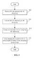
- FIG. 3is a flowchart illustrating one embodiment of a charging method implemented by the wireless charger 2 in FIG. 2 .
- additional stepsmay be added, others deleted, and the ordering of the steps may be changed.
- step S 10the RF conversion unit 20 receives RF from the wireless power transmitter 1 and generates AC electricity.
- the RF conversion unit 20uses the induction coil to generate the AC electricity.
- step S 12the voltage conversion unit 22 converts the AC electricity to DC electricity.
- the voltage conversion unit 22enables the rectifier and converts the AC electricity to the DC electricity using the rectifier. Additionally, the voltage conversion unit 22 controls a voltage of the DC electricity to be equal to a charging voltage (e.g., 5.0 V) required by the electronic device 3 .
- a charging voltagee.g., 5.0 V
- step S 14the voltage conversion unit 22 charges the electronic device 3 using the DC electricity.
- step S 16the voltage conversion unit 22 stops charging the electronic device 3 when the built-in battery of the electronic device 3 is full.
- the voltage conversion unit 22obtains a battery voltage of the built-in battery from the electronic device 3 and determines whether the battery voltage is equal to a specified value (e.g., 3.7 V). The specified value is required by the electronic device 3 .
- the voltage conversion unit 22determines that the built-in battery of the electronic device 3 is full, under the condition that the battery voltage is equal to the specified value. Additionally, the voltage conversion unit 22 sends commands to the RF conversion unit 20 and requests the RF conversion unit 20 to stop generating the AC electricity when the built-in battery of the electronic device 3 is full.
- FIG. 4is an isometric view of a second embodiment of the wireless charger in FIG. 1 .
- the wireless charger 2further includes a switch device 24 , a voltage sensor 26 and an interface 28 .
- the switch device 24includes a first switch 240 and a second switch 242 .
- the RF conversion unit 20is connected to the voltage conversion unit 22 .
- the voltage sensor 26is connected to the RF conversion unit 20 , the switch device 24 and the interface 28 .
- the voltage conversion unit 22is connected to the first switch 240 , and the interface 28 is connected to the second switch 242 and the wired charger 4 .
- the first switch 240 and the second switchare connected to the electronic device 3 .
- the RF conversion unit 20receives RF from the wireless power transmitter 1 and generates AC electricity.
- the voltage conversion unit 22coverts the AC electricity to DC electricity and charges the electronic device 3 using the DC electricity.
- the switch device 24provides an option for a user to charge the electronic device 3 using the wireless charger 2 or the wired charger 4 .
- the first switch 240is turned on and the second switch 242 is turned off, the electronic device 3 is charged by the wireless charger 2 .
- the first switch 240is turned off and the second switch 242 is turned on, the electronic device 3 is charged by the wired charger 4 .
- the voltage sensor 26is used to check a voltage signal of the RF conversion unit 20 and the interface. In one embodiment, if a voltage signal is detected from the RF conversion unit 20 , it is indicated that the electronic device 3 can be charged by the wireless charger 2 . If a voltage signal is detected from? the interface 28 , it is indicated that the electronic 3 can be charged by the wired charger 4 . Additionally, in other embodiments, the voltage sensor 26 can control the switch device 24 . In one embodiment, the voltage sensor 26 controls the first switch 240 to turn on and controls the second switch 242 to turn off, so that the electronic device 3 is charged by the wireless charger 2 . The voltage sensor 26 can control the first switch 240 to turn off and the second switch 242 to turn on, so that the electronic device 3 is charged by the wired charger 4 .
- the voltage conversion unit 22stops charging the electronic device 3 when the built-in battery of the electronic device 3 is full. In one embodiment, if the built-in battery of the electronic device 3 is full, the voltage sensor 26 controls the first switch 240 to turn off and controls the second switch 242 to turn off, so that the voltage conversion unit 22 cannot provide the DC electricity to the electronic device 3 . Furthermore, the voltage conversion unit 22 controls the RF conversion unit 20 to stop generating the AC electricity.
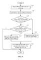
- FIG. 5is a flowchart illustrating one embodiment of a charging method implemented by the wireless charger 2 in FIG. 4 .
- step S 20the RF conversion unit 20 receives RF from the wireless power transmitter 1 and generates AC electricity.
- step S 21the voltage conversion unit 22 converts the AC electricity to the DC electricity.
- step S 22the voltage sensor 26 determines whether any voltage signal is detected from the interface 28 . If the interface 28 has the voltage signal, the procedure goes to step S 24 . Otherwise, if the interface 28 has no voltage signal, the procedure goes to step S 23 .
- step S 23the voltage sensor 26 determines whether any voltage signal is detected from the RF conversion unit 20 . If the RF conversion unit 20 has the voltage signal, the procedure goes to step 25 . Otherwise, if the RF conversion unit 20 has no voltage signal, the procedure ends.
- step S 24the voltage sensor 26 controls the first switch 240 to turn off and controls the second switch 242 to turn on, and the wired charger 4 charges electronic device 3 .
- step S 25the voltage sensor 26 controls the first switch 240 to turn on and controls the second switch 242 to turn off, and the wireless charger 2 charges the electronic device 3 .
- step S 26the voltage sensor 26 controls the first switch 240 to turn off and controls the second switch 242 to turn off when the built-in battery of the electronic device 3 is full.
Landscapes
- Engineering & Computer Science (AREA)
- Power Engineering (AREA)
- Computer Networks & Wireless Communication (AREA)
- Charge And Discharge Circuits For Batteries Or The Like (AREA)
Abstract
Description
Claims (14)
Applications Claiming Priority (3)
| Application Number | Priority Date | Filing Date | Title |
|---|---|---|---|
| TW102109761 | 2013-03-19 | ||
| TW102109761A | 2013-03-19 | ||
| TW102109761ATWI578660B (en) | 2013-03-19 | 2013-03-19 | Wireless charging device and charging method thereof |
Publications (2)
| Publication Number | Publication Date |
|---|---|
| US20140285159A1 US20140285159A1 (en) | 2014-09-25 |
| US9537345B2true US9537345B2 (en) | 2017-01-03 |
Family
ID=51568693
Family Applications (1)
| Application Number | Title | Priority Date | Filing Date |
|---|---|---|---|
| US14/192,741Expired - Fee RelatedUS9537345B2 (en) | 2013-03-19 | 2014-02-27 | Wireless charger and charging method |
Country Status (2)
| Country | Link |
|---|---|
| US (1) | US9537345B2 (en) |
| TW (1) | TWI578660B (en) |
Cited By (5)
| Publication number | Priority date | Publication date | Assignee | Title |
|---|---|---|---|---|
| US11272861B1 (en)* | 2012-09-25 | 2022-03-15 | Micro Mobio Corporation | Personal cloud with a plurality of modular capabilities |
| US11476717B2 (en) | 2017-09-29 | 2022-10-18 | Hewlett-Packard Development Company, L.P. | Transmission of wireless power |
| US11553857B1 (en) | 2012-09-25 | 2023-01-17 | Micro Mobio Corporation | System and method for through window personal cloud transmission |
| US11877842B1 (en) | 2012-09-25 | 2024-01-23 | Micro Mobio Corporation | Personal cloud with a plurality of modular capabilities |
| US12150755B1 (en) | 2012-09-25 | 2024-11-26 | Micro Mobio Corporation | Integrated display with antenna system and method |
Families Citing this family (3)
| Publication number | Priority date | Publication date | Assignee | Title |
|---|---|---|---|---|
| CN106100031B (en)* | 2016-06-30 | 2018-10-26 | 宇龙计算机通信科技(深圳)有限公司 | A kind of charging circuit, charging method and terminal |
| US10615613B2 (en)* | 2016-11-09 | 2020-04-07 | Thames Technology Holdings, Inc. | Controllable charging systems and methods |
| CN106684978A (en)* | 2016-12-19 | 2017-05-17 | 宇龙计算机通信科技(深圳)有限公司 | Charging circuit, charging control method of charging circuit, and terminal |
Citations (6)
| Publication number | Priority date | Publication date | Assignee | Title |
|---|---|---|---|---|
| US20050162131A1 (en)* | 2003-10-27 | 2005-07-28 | Hiromitsu Sennami | Battery packs |
| US20090033280A1 (en)* | 2006-01-31 | 2009-02-05 | Sung-Uk Choi | Contact-less power supply, contact-less charger systems and method for charging rechargeable battery cell |
| US20100194336A1 (en)* | 2007-10-18 | 2010-08-05 | Powermat Ltd. | Inductively chargeable audio devices |
| US20110156636A1 (en)* | 2009-12-28 | 2011-06-30 | Kim Bong-Young | Battery pack and method of controlling charging of battery pack |
| US20110241615A1 (en)* | 2010-03-30 | 2011-10-06 | Winharbor Technology Co., Ltd. | Adapter capable of wireless charging |
| US20120146576A1 (en)* | 2010-06-11 | 2012-06-14 | Mojo Mobility, Inc. | System for wireless power transfer that supports interoperability, and multi-pole magnets for use therewith |
Family Cites Families (1)
| Publication number | Priority date | Publication date | Assignee | Title |
|---|---|---|---|---|
| TW200639397A (en)* | 2005-05-10 | 2006-11-16 | Tse-Chuan Chou | Multi-purpose electrochemical type sensing system integrated with wireless telemetry |
- 2013
- 2013-03-19TWTW102109761Apatent/TWI578660B/enactive
- 2014
- 2014-02-27USUS14/192,741patent/US9537345B2/ennot_activeExpired - Fee Related
Patent Citations (6)
| Publication number | Priority date | Publication date | Assignee | Title |
|---|---|---|---|---|
| US20050162131A1 (en)* | 2003-10-27 | 2005-07-28 | Hiromitsu Sennami | Battery packs |
| US20090033280A1 (en)* | 2006-01-31 | 2009-02-05 | Sung-Uk Choi | Contact-less power supply, contact-less charger systems and method for charging rechargeable battery cell |
| US20100194336A1 (en)* | 2007-10-18 | 2010-08-05 | Powermat Ltd. | Inductively chargeable audio devices |
| US20110156636A1 (en)* | 2009-12-28 | 2011-06-30 | Kim Bong-Young | Battery pack and method of controlling charging of battery pack |
| US20110241615A1 (en)* | 2010-03-30 | 2011-10-06 | Winharbor Technology Co., Ltd. | Adapter capable of wireless charging |
| US20120146576A1 (en)* | 2010-06-11 | 2012-06-14 | Mojo Mobility, Inc. | System for wireless power transfer that supports interoperability, and multi-pole magnets for use therewith |
Cited By (5)
| Publication number | Priority date | Publication date | Assignee | Title |
|---|---|---|---|---|
| US11272861B1 (en)* | 2012-09-25 | 2022-03-15 | Micro Mobio Corporation | Personal cloud with a plurality of modular capabilities |
| US11553857B1 (en) | 2012-09-25 | 2023-01-17 | Micro Mobio Corporation | System and method for through window personal cloud transmission |
| US11877842B1 (en) | 2012-09-25 | 2024-01-23 | Micro Mobio Corporation | Personal cloud with a plurality of modular capabilities |
| US12150755B1 (en) | 2012-09-25 | 2024-11-26 | Micro Mobio Corporation | Integrated display with antenna system and method |
| US11476717B2 (en) | 2017-09-29 | 2022-10-18 | Hewlett-Packard Development Company, L.P. | Transmission of wireless power |
Also Published As
| Publication number | Publication date |
|---|---|
| TWI578660B (en) | 2017-04-11 |
| TW201438368A (en) | 2014-10-01 |
| US20140285159A1 (en) | 2014-09-25 |
Similar Documents
| Publication | Publication Date | Title |
|---|---|---|
| US9537345B2 (en) | Wireless charger and charging method | |
| KR102847612B1 (en) | Apparatus for Wireless Power Transmission | |
| KR102481953B1 (en) | Wireless power transmitter and method for controlling thereof | |
| CN109874361B (en) | Wireless power receiver and method for controlling wireless power receiver | |
| JP6607669B2 (en) | Wireless charging apparatus and charging method thereof | |
| JP2017506873A (en) | Monitoring or controlling charging current in a resonantly regulated inductive charger | |
| TW201603438A (en) | Apparatus, system and method of wireless power transfer | |
| KR20160109955A (en) | Method for generating a load of wireless power receiving unit in wireless charge system and the wireless power receiving unit | |
| KR20200032421A (en) | Apparatus for Transmitting and Receiving the Amount of Power consumed in order to Identify Transmit Efficiency related on Wireless Power Transmission and the Method for Controlling thereof | |
| CN103296786A (en) | Wireless power receiver and controlling method thereof | |
| KR102423599B1 (en) | Wireless power transmitter and method for controlling the same | |
| US9450448B2 (en) | Wireless charging device and electric energy recycling method thereof | |
| KR101740924B1 (en) | Portable wireless dual charging battery pack | |
| US20130300351A1 (en) | Wireless transceiver and wireless transceiver system | |
| CN110165735B (en) | Charging method and charging equipment | |
| CN207588505U (en) | A wireless charging desk lamp | |
| KR101712647B1 (en) | Auxiliary battery for wirelessly charging and discharging | |
| CN103779881B (en) | Battery and there is the charging system of this battery | |
| US9762080B2 (en) | Electronic apparatus, system and charging method thereof | |
| TWI538344B (en) | Wireless rechargeable electronic device | |
| KR20120098979A (en) | Power supply apparatus for mobile device using mobile station | |
| JP2015204743A (en) | Portable wireless charging apparatus and system | |
| KR20150016804A (en) | Wireless power receiving apparatus |
Legal Events
| Date | Code | Title | Description |
|---|---|---|---|
| AS | Assignment | Owner name:FIH (HONG KONG) LIMITED, HONG KONG Free format text:ASSIGNMENT OF ASSIGNORS INTEREST;ASSIGNOR:WANG, CHUN-NAN;REEL/FRAME:032318/0595 Effective date:20140225 | |
| STCF | Information on status: patent grant | Free format text:PATENTED CASE | |
| AS | Assignment | Owner name:MOBILE DRIVE TECHNOLOGY CO.,LTD., TAIWAN Free format text:ASSIGNMENT OF ASSIGNORS INTEREST;ASSIGNOR:FIH (HONG KONG) LIMITED;REEL/FRAME:051442/0348 Effective date:20191205 | |
| MAFP | Maintenance fee payment | Free format text:PAYMENT OF MAINTENANCE FEE, 4TH YEAR, LARGE ENTITY (ORIGINAL EVENT CODE: M1551); ENTITY STATUS OF PATENT OWNER: LARGE ENTITY Year of fee payment:4 | |
| AS | Assignment | Owner name:MOBILE DRIVE NETHERLANDS B.V., NETHERLANDS Free format text:ASSIGNMENT OF ASSIGNORS INTEREST;ASSIGNOR:MOBILE DRIVE TECHNOLOGY CO., LTD.;REEL/FRAME:057391/0564 Effective date:20210820 | |
| FEPP | Fee payment procedure | Free format text:MAINTENANCE FEE REMINDER MAILED (ORIGINAL EVENT CODE: REM.); ENTITY STATUS OF PATENT OWNER: LARGE ENTITY | |
| LAPS | Lapse for failure to pay maintenance fees | Free format text:PATENT EXPIRED FOR FAILURE TO PAY MAINTENANCE FEES (ORIGINAL EVENT CODE: EXP.); ENTITY STATUS OF PATENT OWNER: LARGE ENTITY | |
| STCH | Information on status: patent discontinuation | Free format text:PATENT EXPIRED DUE TO NONPAYMENT OF MAINTENANCE FEES UNDER 37 CFR 1.362 | |
| FP | Lapsed due to failure to pay maintenance fee | Effective date:20250103 |