US9537209B2 - Antenna array with reduced mutual coupling between array elements - Google Patents
Antenna array with reduced mutual coupling between array elementsDownload PDFInfo
- Publication number
- US9537209B2 US9537209B2US13/896,181US201313896181AUS9537209B2US 9537209 B2US9537209 B2US 9537209B2US 201313896181 AUS201313896181 AUS 201313896181AUS 9537209 B2US9537209 B2US 9537209B2
- Authority
- US
- United States
- Prior art keywords
- horn
- array
- aperture
- external surface
- adjacent
- Prior art date
- Legal status (The legal status is an assumption and is not a legal conclusion. Google has not performed a legal analysis and makes no representation as to the accuracy of the status listed.)
- Active, expires
Links
Images


Classifications
- H—ELECTRICITY
- H01—ELECTRIC ELEMENTS
- H01Q—ANTENNAS, i.e. RADIO AERIALS
- H01Q1/00—Details of, or arrangements associated with, antennas
- H01Q1/52—Means for reducing coupling between antennas; Means for reducing coupling between an antenna and another structure
- H01Q1/521—Means for reducing coupling between antennas; Means for reducing coupling between an antenna and another structure reducing the coupling between adjacent antennas
- H01Q1/523—Means for reducing coupling between antennas; Means for reducing coupling between an antenna and another structure reducing the coupling between adjacent antennas between antennas of an array
- H—ELECTRICITY
- H01—ELECTRIC ELEMENTS
- H01Q—ANTENNAS, i.e. RADIO AERIALS
- H01Q13/00—Waveguide horns or mouths; Slot antennas; Leaky-waveguide antennas; Equivalent structures causing radiation along the transmission path of a guided wave
- H01Q13/02—Waveguide horns
- H01Q13/0266—Waveguide horns provided with a flange or a choke
- H—ELECTRICITY
- H01—ELECTRIC ELEMENTS
- H01Q—ANTENNAS, i.e. RADIO AERIALS
- H01Q21/00—Antenna arrays or systems
- H01Q21/06—Arrays of individually energised antenna units similarly polarised and spaced apart
- H01Q21/061—Two dimensional planar arrays
- H01Q21/064—Two dimensional planar arrays using horn or slot aerials
Definitions
- This disclosurerelates to a microwave antenna array including multiple horn-like antenna array elements and, more particularly, to an array having at least one horn with a contoured external surface configured to reduce mutual coupling with an adjacent horn.
- the assignee of the present inventionmanufactures and deploys spacecraft for, inter alia, communications and broadcast services.
- Antenna systems for such spacecraftmay include array-fed reflectors, for generating shaped beams corresponding to specific antenna pattern coverage requirements.
- a feed array configured for the transmission of RF energy therethroughmay be communicatively coupled with an antenna reflector and may include an array of multiple feed elements configured as horns.
- Center-to-center spacing d c-c between adjacent horns in such a feed arrayis, desirably, made as small as possible in order to provide a maximal degree of pattern control for the shaped beam.
- d c-cshould be no less than approximately 1.2 ⁇ , where ⁇ is the wavelength corresponding to the lowest frequency of the RF energy (the “characteristic wavelength”).
- d c-cmust exceed the horn aperture outer diameter, d a , so as to ensure a positive “gap” between horns at the aperture plane. This gap may be for example, about 1/20 th of the aperture diameter.
- Aperture efficiencywhich may be characterized by a metric referred to as peak directivity, is a critical performance metric for feed array elements.
- peak directivityFor example, the achievable edge of coverage (EOC) secondary pattern directivity for the shaped beam directly tracks the radiating element's peak directivity.
- EOCedge of coverage
- a 0.1 dB decrease in primary pattern peak directivitymay result in a 0.1 dB decrease in secondary pattern EOC directivity.
- polarization purityor, equivalently, suppression of cross polarization
- radiation efficiencyi.e., the fraction of available power that is actually radiated by the element. Radiation efficiency incorporates the effects of impedance mismatch (return loss) and dissipation loss.
- Performance degradation due to mutual couplingmust be accommodated in communication system link budgets or suppressed.
- Known suppression techniquesentail the use of additional components arranged between the radiating elements.
- U.S. Pat. No. 2,987,747 to Atchisondiscloses that adjacent radiating elements may be shorted together at a distance of one quarter wavelength from a common aperture plane, generating an RF choke that inhibits mutual coupling.
- U.S. Pat. No. 4,115,782 to Handiscloses metal tabs or clips inserted near the apertures of radiating elements to reduce mutual coupling effects.
- 4,219,820 to Craildiscloses a planar metallic shape etched on a dielectric substrate that is inserted into the aperture of circular horn elements to provide coupling compensation between circularly polarized horn antennas to reduce degradation of polarization purity.
- the present inventorshave appreciated that reduced mutual coupling between array elements may be achieved, while avoiding the use of additional components. More particularly, the presently disclosed techniques reduce mutual coupling between radiating elements, particularly horns that would otherwise arise from fields radiated from each horn's aperture and from currents that flow along the horn's exterior surfaces and between horns arranged in an array.
- the array of antenna feed elementsincludes a plurality of horns, each horn having an aperture and configured for transmission of electromagnetic energy therethrough. At least a first horn is configured with an electrically conductive external surface proximate to the aperture, the external surface contoured so as to reduce mutual coupling between the first horn and an adjacent horn. Where the electromagnetic energy is within a radio frequency (RF) band, the external surface is contoured so as to provide an abrupt change in a gap dimension between the first horn and an adjacent horn, the change occurring at a distance behind the aperture approximately equal to an integer multiple of one half the characteristic wavelength of the RF band.
- RFradio frequency
- an array of antenna feed elementsincludes a plurality of horns.
- Each hornincludes an aperture at a distal end of the horn, configured for transmission of electromagnetic energy therethrough.
- At least a first hornis configured with an electrically conductive external surface proximate to the aperture, the external surface being contoured so as to reduce mutual coupling between the first horn and an adjacent horn.
- the energyis within a radio frequency (RF) band
- the first hornhas an aperture external diameter d a
- the first hornis separated from the adjacent horn by a center to center distance d c-c .
- the external surfacemay be contoured so as to include at least a first portion and a second portion.
- the first portionmay have a length l that extends from a longitudinal position proximate to the aperture toward a proximal end of the horn.
- the first portionmay be contoured so as to provide, proximate to each adjacent horn, a first lateral gap between the first portion and an external surface of the adjacent horn.
- the first lateral gapmay be approximately constant, throughout length l, length l being approximately n ⁇ /2, where ⁇ is a characteristic wavelength of the RF band and n is a positive integer.
- the second portion of the external surfacemay extend from the first portion toward an axial position proximate to the distal end, and provide, proximate to the adjacent horn, a second lateral gap significantly larger than the first lateral gap.
- the first lateral gapmay be approximately equal to the difference between d c-c and d a .
- nmay equal one.
- the first lateral gapmay be no greater than d a /10.
- each hornmay include an electrically conductive interior surface.
- the interior surfacemay be shaped as a truncated cone.
- the interior surfacemay include one or more of a step, a taper, corrugations, and/or ridges.
- a cross section of the first horn, parallel to the aperturemay be circular, square, rectangular or hexagonal.
- the hornsmay be disposed in an array that conforms to a geometric plane, plane, or to a surface of revolution having a minimum radius of curvature that is significantly larger than the horn separation d c-c , or to any other gently curved geometric shape.
- an antenna feed elementis configured as a horn, the horn comprising an aperture at a distal end of the horn, and configured for transmission of electromagnetic energy therethrough, the energy being within a radio frequency (RF) band, the horn being configured with an electrically conductive external surface proximate to the aperture, the external surface being contoured so as to reduce mutual coupling between the horn and an adjacent horn.
- RFradio frequency
- an antenna systemincludes an array of antenna feed elements illuminating a reflector, the array including a plurality of horns, each horn comprising an aperture at a distal end of the horn, and configured for transmission of electromagnetic energy therethrough, the energy being within a radio frequency (RF) band, at least a first horn being configured with an electrically conductive external surface proximate to the aperture, the external surface being contoured so as to reduce mutual coupling between the first horn and an adjacent horn.
- RFradio frequency
- FIG. 1illustrates array of feed elements each feed element configured as a circular horn antenna
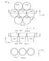
- FIG. 2illustrates a comparison between conventional horn antennas and horn antennas configured in accordance with the present teachings.
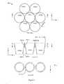
- FIG. 3illustrates an array of antenna feed elements, according to an implementation.
- FIG. 4illustrates an array of antenna feed elements, according to another implementation.
- FIG. 5illustrates a horn antenna, according to an implementation.
- FIG. 6illustrates a comparison of mutual coupling performance of arrays of antenna feed elements.
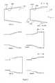
- FIG. 7illustrates a comparison of co-polarization directivity.
- FIG. 8illustrates a comparison of normalized cross polarization amplitude.
- spacecraftspacecraft
- spacecraftspacecraft
- satellitespacecraft
- vehiclevehicle
- transmissionrelates to RF band electromagnetic energy coupled across an aperture of a horn antenna, and encompasses either or both of energy that is emitted by the horn antenna and energy that is received by the horn antenna.
- the present inventorhas appreciated that mutual coupling between a first horn and an adjacent horn of an array of antenna feed horns may be reduced by providing the first horn with an electrically conductive external surface having a contoured shape as described hereinbelow.
- FIG. 1illustrates an array 100 of feed elements 110 ( i ).
- array 100includes 19 feed elements, each configured as a circular horn antenna, arranged in a triangular lattice. A greater or smaller number of horns may be contemplated, and the array may include horns arranged in other regular or irregular lattice-like arrangements. For example, the array may be configured as a square lattice.
- Each horn 110 ( i )may have an aperture 111 of diameter d a . Aperture 111 of each horn may be substantially coplanar with apertures of other horns in the array.
- an x-y plane, parallel to the aperture planeis defined.
- a distance in the x-y planemay be referred to as a lateral distance, whereas a distance in a z-direction orthogonal to the x-y plane may be referred to as a longitudinal or axial distance.
- aperture 111may be referred to as being disposed at a distal end of the horn, an end opposite to which may be referred to as a proximal end.
- a position between the distal end of the horn and the proximal end of the hornmay be referred to as being “behind” the aperture.
- each hornis separated from an adjacent horn by a center-to-center distance d c-c which is at least slightly larger than d a , so as to assure a positive gap distance g between two adjacent horns at the point of closest approach between the horns. It is desirable that gap g be small relative to d a . For example, g may be about 1/20 th of d a .
- Each hornmay be formed of a conductive material configured in a generally conical shape, having a wall thickness T w .
- T wwill be fairly uniform along the longitudinal direction, and small relative to d a .
- T wmay be no thicker than determined to be necessary to provide a desired structural rigidity, for example.
- FIG. 2a comparison between conventional horn antennas and horn antennas configured in accordance with the present teachings is illustrated.
- a cross section of a simple conical horn antenna 210 a of the prior artis illustrated.
- a horn antenna 210 bconfigured in accordance with the present teachings is illustrated.
- Horn antenna 210 bmay include electrically conductive interior surface 230 b and electrically conductive exterior surface 220 b . It will be appreciated that electrically conductive interior surface 230 b and electrically conductive exterior surface 220 b may be respective surfaces of an integral electrically conductive wall.
- Interior surface 230 b of horn antenna 210 bmay be arranged in substantially the same shape as interior surface 230 a of horn antenna 210 a .
- Exterior surface 220 bis, advantageously, contoured to so as to reduce mutual coupling between horn 210 b and an adjacent horn (not illustrated).
- external surface 220 bmay be contoured so as to include a first portion 221 b and a second portion 222 b .
- First portion 221 bextends a length ⁇ /2 in the longitudinal direction from the plane of aperture 211 b of horn 210 b toward proximal end 212 b . It will be appreciated that ⁇ /2 represents a distance that is one half the characteristic wavelength of electromagnetic energy desired to be transmitted through horn 210 b .
- a first lateral gap between first portion 221 b and an external surface of the adjacent hornmay be approximately constant as a function of longitudinal position.
- Second portion 222 b of external surface 220 bextends from first portion 221 b toward an axial position proximate to proximal end 212 b of horn 210 b .
- second portion 222 bprovides, proximate to the adjacent horn (not illustrated), a second lateral gap that is substantially larger than the first lateral gap.
- a gap between adjacent hornsis relatively narrow and constant for a longitudinal distance (“gap length”) of ⁇ /2.
- this gapmay behave, effectively, as a waveguide transmission line for electromagnetic energy associated with RF signals being transmitted through horn 210 b .
- the gapis relatively constant and narrow and will therefore have a relatively low characteristic impedance.
- the gap widthmay increase in size by a factor of about two or more.
- the transition in gap widthoccurs abruptly and the characteristic impedance of the effective waveguide transmission line becomes abruptly much larger at the point of transition.
- the abrupt change in gap widthmay occur as a result in a step change in external diameter, as illustrated, or by use of a steep taper, for example.
- an open circuit termination of the transmission lineis effectively created, the transmission line therefore being approximately one half wavelength in length.
- the approximately half wavelength transmission linemay reflect this high impedance termination to the aperture plane.
- contouring the horn external surface so as to provide an abrupt change in gap dimension as described abovemay produce an RF choke that substantially decreases mutual couplings between the horns enhances the radiation properties of each horn.
- Detail A and Detail Billustrate an interior surface arranged in the shape of a simple truncated cone
- the principles of the presently disclosed techniquesmay be applied to horns of any interior configuration.
- Known horn antennasmay have various steps, tapers, corrugations, and/or ridges to achieve various performance objectives.
- an exterior wallmay approximately follow those variations in contour, as illustrated in Detail C and Detail E so as to minimize mass.
- an array 300 of antenna feed elementsincluding seven horns arranged in a triangular lattice is illustrated.
- the “Plan View”illustrates a view of the aperture plane taken along the z-axis.
- an individual horn 310 ( i )may be proximate to up to six “adjacent” horns.
- horn 310 ( 1 )is illustrated as being adjacent to each of horn 310 ( 2 ), horn 310 ( 3 ), horn 310 ( 4 ), horn 310 ( 5 ), horn 310 ( 6 ), and horn 310 ( 7 ).
- the hornsmay be arranged such that an approximately identical gap g is provided between each pair of adjacent horns.
- adjacent hornsmay be configured and arranged such that gap g is approximately constant along a longitudinal gap length distance ⁇ /2 that extends from the aperture plane toward the distal end.
- ⁇may be a characteristic wavelength of the RF band desired to be transmitted through the horn. More particularly, referring now to adjacent horns 310 ( 1 ) and 310 ( 4 ), it is illustrated how first portion 321 ( 1 ) of horn 310 ( 1 ) and first portion 321 ( 4 ) of horn 310 ( 4 ) are configured so as to provide a constant gap g.
- second portion 322 ( 1 ) of horn 310 ( 1 ) and second portion 322 ( 4 ) of horn 310 ( 4 )are configured so as to provide a lateral separation substantially larger than gap g.
- first portion 321 ( 1 )may have a circular cross section.
- the circular cross sectionmay be approximately equal to aperture diameter d a .
- an array 400 of antenna feed elementsincluding seven horns arranged in a triangular lattice is illustrated.
- the “Plan view”illustrates a view of the aperture plane taken along the Z-axis.
- the hornsmay be arranged such that an approximately identical gap g is provided between each pair of adjacent horns.
- adjacent hornsmay be configured and arranged such that gap g is approximately constant along an axial distance ⁇ /2 extending from aperture plane 411 ( i ) toward proximal end 412 ( i ).
- ⁇may be a characteristic wavelength of the RF band desired to be transmitted through the horn.
- first portion 421 ( i )may have a scalloped circumference, such that only regions of the circumference proximate to an adjacent horn have a radius approximately equal to one half aperture diameter d a . Regions of the circumference not proximate to an adjacent horn may have a smaller radius, so as to minimize wall thickness, for example.
- a profile of first portion 421 ( i )may be configured such a that the transmission line profile has a meander or wave-like deviation from a straight longitudinal direction in order to decrease a z-axis dimension of the transmission line.
- a horn antenna 510 having a circular cross sectionconfigured in accordance with the presently disclosed techniques is illustrated.
- the illustrated implementationmay be suitable for operation with circularly polarized RF energy within a frequency range of 12.4-12.7 GHz.
- an outside diameter of horn antenna 510is approximately constant for a distance ⁇ /2 extending from aperture plane 511 toward proximal end 512 .
- ⁇may be a characteristic wavelength of the RF band desired to be transmitted through the horn.
- ⁇may be the free space wavelength of electromagnetic radiation at a center frequency within the range 12.4-12.7 GHz, for example.
- Plot Aillustrates mutual coupling performance of an array horn antennas 510 operating at 12.6 GHz in a dual polarized mode. More particularly, for a unit amount of power input to horn antenna 510 ( 1 ) at a first polarization (for example, left hand circular polarization (LCHP)) an amount of power coupled into neighboring elements at a second polarization (for example, right hand circular polarization) is indicated, expressed in dB. It will be observed that, for horns adjacent to 510 ( 1 ) mutual coupling is limited to about ⁇ 45 dB.
- a first polarizationfor example, left hand circular polarization (LCHP)
- a second polarizationfor example, right hand circular polarization
- Horn antenna 610 ( 1 )is an antenna of the prior art which, for purposes of this comparison, is assumed to have interior surfaces configured identically to horn antenna 510 ( 1 ), and be operating at the same frequency and dual polarized mode. It will be observed that mutual coupling between horn antenna 610 ( 1 ) and neighboring elements is about ⁇ 42 dB, or about 3 dB worse than for horn antenna 510 ( 1 ).
- FIG. 7presents a plot of co-polarization (“copol”) directivity for horn antenna 510 ( 1 ), and 610 ( 1 ), when operating in respective arrays as illustrated in FIG. 6 . More particularly, the peak partial directivity to right-hand circular polarization (RHCP) of the center elements 510 ( 1 ) and 610 ( 1 ) of the arrays shown in FIG. 6 is plotted as a function of frequency when said center elements are excited for intended RHCP operation. It may be observed that horn antenna 510 ( 1 ) exhibits an improvement in copol directivity of about 0.12 dB to 0.16 dB relative to performance of horn antenna 610 ( 1 ) of the prior art.
- copolco-polarization
- FIG. 8presents a plot of normalized cross polarization amplitude. More particularly, FIG. 8 illustrates normalized LCHP pattern amplitude of an array horn antenna 510 operating at 12.6 GHz when the horn is excited for intended RHCP operation.
- normalized cross polarization pattern amplitudeexpressed in dB relative to the copol peak amplitude, is plotted as a function of angle ⁇ from boresight for a number of azimuthal planes.
- Cross-polarizationis shown to be limited to no worse (i.e. no higher) than ⁇ 33 dB with respect to peak copol directivity.
Landscapes
- Waveguide Aerials (AREA)
- Variable-Direction Aerials And Aerial Arrays (AREA)
Abstract
Description
Claims (18)
Priority Applications (1)
| Application Number | Priority Date | Filing Date | Title |
|---|---|---|---|
| US13/896,181US9537209B2 (en) | 2013-05-16 | 2013-05-16 | Antenna array with reduced mutual coupling between array elements |
Applications Claiming Priority (1)
| Application Number | Priority Date | Filing Date | Title |
|---|---|---|---|
| US13/896,181US9537209B2 (en) | 2013-05-16 | 2013-05-16 | Antenna array with reduced mutual coupling between array elements |
Publications (2)
| Publication Number | Publication Date |
|---|---|
| US20140340271A1 US20140340271A1 (en) | 2014-11-20 |
| US9537209B2true US9537209B2 (en) | 2017-01-03 |
Family
ID=51895372
Family Applications (1)
| Application Number | Title | Priority Date | Filing Date |
|---|---|---|---|
| US13/896,181Active2034-12-17US9537209B2 (en) | 2013-05-16 | 2013-05-16 | Antenna array with reduced mutual coupling between array elements |
Country Status (1)
| Country | Link |
|---|---|
| US (1) | US9537209B2 (en) |
Cited By (1)
| Publication number | Priority date | Publication date | Assignee | Title |
|---|---|---|---|---|
| US10615495B1 (en) | 2017-09-25 | 2020-04-07 | National Technology & Engineering Solutions Of Sandia, Llc | Ultra-wideband mutual coupling compensation of active electronically scanned arrays in multi-channel radar systems |
Families Citing this family (125)
| Publication number | Priority date | Publication date | Assignee | Title |
|---|---|---|---|---|
| US9525524B2 (en) | 2013-05-31 | 2016-12-20 | At&T Intellectual Property I, L.P. | Remote distributed antenna system |
| US9999038B2 (en) | 2013-05-31 | 2018-06-12 | At&T Intellectual Property I, L.P. | Remote distributed antenna system |
| US8897697B1 (en) | 2013-11-06 | 2014-11-25 | At&T Intellectual Property I, Lp | Millimeter-wave surface-wave communications |
| US9768833B2 (en) | 2014-09-15 | 2017-09-19 | At&T Intellectual Property I, L.P. | Method and apparatus for sensing a condition in a transmission medium of electromagnetic waves |
| US10063280B2 (en) | 2014-09-17 | 2018-08-28 | At&T Intellectual Property I, L.P. | Monitoring and mitigating conditions in a communication network |
| US9615269B2 (en) | 2014-10-02 | 2017-04-04 | At&T Intellectual Property I, L.P. | Method and apparatus that provides fault tolerance in a communication network |
| US9685992B2 (en) | 2014-10-03 | 2017-06-20 | At&T Intellectual Property I, L.P. | Circuit panel network and methods thereof |
| US9503189B2 (en) | 2014-10-10 | 2016-11-22 | At&T Intellectual Property I, L.P. | Method and apparatus for arranging communication sessions in a communication system |
| US9973299B2 (en) | 2014-10-14 | 2018-05-15 | At&T Intellectual Property I, L.P. | Method and apparatus for adjusting a mode of communication in a communication network |
| US9577306B2 (en) | 2014-10-21 | 2017-02-21 | At&T Intellectual Property I, L.P. | Guided-wave transmission device and methods for use therewith |
| US9312919B1 (en) | 2014-10-21 | 2016-04-12 | At&T Intellectual Property I, Lp | Transmission device with impairment compensation and methods for use therewith |
| US9780834B2 (en) | 2014-10-21 | 2017-10-03 | At&T Intellectual Property I, L.P. | Method and apparatus for transmitting electromagnetic waves |
| US9627768B2 (en) | 2014-10-21 | 2017-04-18 | At&T Intellectual Property I, L.P. | Guided-wave transmission device with non-fundamental mode propagation and methods for use therewith |
| US9653770B2 (en) | 2014-10-21 | 2017-05-16 | At&T Intellectual Property I, L.P. | Guided wave coupler, coupling module and methods for use therewith |
| US9769020B2 (en) | 2014-10-21 | 2017-09-19 | At&T Intellectual Property I, L.P. | Method and apparatus for responding to events affecting communications in a communication network |
| US9742462B2 (en) | 2014-12-04 | 2017-08-22 | At&T Intellectual Property I, L.P. | Transmission medium and communication interfaces and methods for use therewith |
| US9544006B2 (en) | 2014-11-20 | 2017-01-10 | At&T Intellectual Property I, L.P. | Transmission device with mode division multiplexing and methods for use therewith |
| US10009067B2 (en) | 2014-12-04 | 2018-06-26 | At&T Intellectual Property I, L.P. | Method and apparatus for configuring a communication interface |
| US10340573B2 (en) | 2016-10-26 | 2019-07-02 | At&T Intellectual Property I, L.P. | Launcher with cylindrical coupling device and methods for use therewith |
| US10243784B2 (en) | 2014-11-20 | 2019-03-26 | At&T Intellectual Property I, L.P. | System for generating topology information and methods thereof |
| US9997819B2 (en) | 2015-06-09 | 2018-06-12 | At&T Intellectual Property I, L.P. | Transmission medium and method for facilitating propagation of electromagnetic waves via a core |
| US9461706B1 (en) | 2015-07-31 | 2016-10-04 | At&T Intellectual Property I, Lp | Method and apparatus for exchanging communication signals |
| US9800327B2 (en) | 2014-11-20 | 2017-10-24 | At&T Intellectual Property I, L.P. | Apparatus for controlling operations of a communication device and methods thereof |
| US9954287B2 (en) | 2014-11-20 | 2018-04-24 | At&T Intellectual Property I, L.P. | Apparatus for converting wireless signals and electromagnetic waves and methods thereof |
| WO2016127393A1 (en)* | 2015-02-13 | 2016-08-18 | 华为技术有限公司 | Reflection surface antenna and feed source thereof |
| US9876570B2 (en) | 2015-02-20 | 2018-01-23 | At&T Intellectual Property I, Lp | Guided-wave transmission device with non-fundamental mode propagation and methods for use therewith |
| US9749013B2 (en) | 2015-03-17 | 2017-08-29 | At&T Intellectual Property I, L.P. | Method and apparatus for reducing attenuation of electromagnetic waves guided by a transmission medium |
| US10224981B2 (en) | 2015-04-24 | 2019-03-05 | At&T Intellectual Property I, Lp | Passive electrical coupling device and methods for use therewith |
| US9705561B2 (en) | 2015-04-24 | 2017-07-11 | At&T Intellectual Property I, L.P. | Directional coupling device and methods for use therewith |
| US9793954B2 (en) | 2015-04-28 | 2017-10-17 | At&T Intellectual Property I, L.P. | Magnetic coupling device and methods for use therewith |
| US9871282B2 (en) | 2015-05-14 | 2018-01-16 | At&T Intellectual Property I, L.P. | At least one transmission medium having a dielectric surface that is covered at least in part by a second dielectric |
| US9490869B1 (en) | 2015-05-14 | 2016-11-08 | At&T Intellectual Property I, L.P. | Transmission medium having multiple cores and methods for use therewith |
| US9748626B2 (en) | 2015-05-14 | 2017-08-29 | At&T Intellectual Property I, L.P. | Plurality of cables having different cross-sectional shapes which are bundled together to form a transmission medium |
| US10650940B2 (en) | 2015-05-15 | 2020-05-12 | At&T Intellectual Property I, L.P. | Transmission medium having a conductive material and methods for use therewith |
| US9917341B2 (en) | 2015-05-27 | 2018-03-13 | At&T Intellectual Property I, L.P. | Apparatus and method for launching electromagnetic waves and for modifying radial dimensions of the propagating electromagnetic waves |
| US10812174B2 (en) | 2015-06-03 | 2020-10-20 | At&T Intellectual Property I, L.P. | Client node device and methods for use therewith |
| US9912381B2 (en) | 2015-06-03 | 2018-03-06 | At&T Intellectual Property I, Lp | Network termination and methods for use therewith |
| US9866309B2 (en) | 2015-06-03 | 2018-01-09 | At&T Intellectual Property I, Lp | Host node device and methods for use therewith |
| US9913139B2 (en) | 2015-06-09 | 2018-03-06 | At&T Intellectual Property I, L.P. | Signal fingerprinting for authentication of communicating devices |
| US9820146B2 (en) | 2015-06-12 | 2017-11-14 | At&T Intellectual Property I, L.P. | Method and apparatus for authentication and identity management of communicating devices |
| US9667317B2 (en) | 2015-06-15 | 2017-05-30 | At&T Intellectual Property I, L.P. | Method and apparatus for providing security using network traffic adjustments |
| US9509415B1 (en) | 2015-06-25 | 2016-11-29 | At&T Intellectual Property I, L.P. | Methods and apparatus for inducing a fundamental wave mode on a transmission medium |
| US9640850B2 (en) | 2015-06-25 | 2017-05-02 | At&T Intellectual Property I, L.P. | Methods and apparatus for inducing a non-fundamental wave mode on a transmission medium |
| US9865911B2 (en) | 2015-06-25 | 2018-01-09 | At&T Intellectual Property I, L.P. | Waveguide system for slot radiating first electromagnetic waves that are combined into a non-fundamental wave mode second electromagnetic wave on a transmission medium |
| US9853342B2 (en) | 2015-07-14 | 2017-12-26 | At&T Intellectual Property I, L.P. | Dielectric transmission medium connector and methods for use therewith |
| US9722318B2 (en) | 2015-07-14 | 2017-08-01 | At&T Intellectual Property I, L.P. | Method and apparatus for coupling an antenna to a device |
| US10205655B2 (en) | 2015-07-14 | 2019-02-12 | At&T Intellectual Property I, L.P. | Apparatus and methods for communicating utilizing an antenna array and multiple communication paths |
| US9882257B2 (en) | 2015-07-14 | 2018-01-30 | At&T Intellectual Property I, L.P. | Method and apparatus for launching a wave mode that mitigates interference |
| US10044409B2 (en) | 2015-07-14 | 2018-08-07 | At&T Intellectual Property I, L.P. | Transmission medium and methods for use therewith |
| US9847566B2 (en) | 2015-07-14 | 2017-12-19 | At&T Intellectual Property I, L.P. | Method and apparatus for adjusting a field of a signal to mitigate interference |
| US10320586B2 (en) | 2015-07-14 | 2019-06-11 | At&T Intellectual Property I, L.P. | Apparatus and methods for generating non-interfering electromagnetic waves on an insulated transmission medium |
| US10148016B2 (en) | 2015-07-14 | 2018-12-04 | At&T Intellectual Property I, L.P. | Apparatus and methods for communicating utilizing an antenna array |
| US9628116B2 (en) | 2015-07-14 | 2017-04-18 | At&T Intellectual Property I, L.P. | Apparatus and methods for transmitting wireless signals |
| US9793951B2 (en) | 2015-07-15 | 2017-10-17 | At&T Intellectual Property I, L.P. | Method and apparatus for launching a wave mode that mitigates interference |
| US10090606B2 (en) | 2015-07-15 | 2018-10-02 | At&T Intellectual Property I, L.P. | Antenna system with dielectric array and methods for use therewith |
| US9912027B2 (en) | 2015-07-23 | 2018-03-06 | At&T Intellectual Property I, L.P. | Method and apparatus for exchanging communication signals |
| US9749053B2 (en) | 2015-07-23 | 2017-08-29 | At&T Intellectual Property I, L.P. | Node device, repeater and methods for use therewith |
| US9948333B2 (en) | 2015-07-23 | 2018-04-17 | At&T Intellectual Property I, L.P. | Method and apparatus for wireless communications to mitigate interference |
| US9871283B2 (en) | 2015-07-23 | 2018-01-16 | At&T Intellectual Property I, Lp | Transmission medium having a dielectric core comprised of plural members connected by a ball and socket configuration |
| US9735833B2 (en) | 2015-07-31 | 2017-08-15 | At&T Intellectual Property I, L.P. | Method and apparatus for communications management in a neighborhood network |
| US9967173B2 (en) | 2015-07-31 | 2018-05-08 | At&T Intellectual Property I, L.P. | Method and apparatus for authentication and identity management of communicating devices |
| US20170040709A1 (en)* | 2015-08-04 | 2017-02-09 | Nidec Elesys Corporation | Radar apparatus |
| US9904535B2 (en) | 2015-09-14 | 2018-02-27 | At&T Intellectual Property I, L.P. | Method and apparatus for distributing software |
| US9769128B2 (en) | 2015-09-28 | 2017-09-19 | At&T Intellectual Property I, L.P. | Method and apparatus for encryption of communications over a network |
| US9729197B2 (en) | 2015-10-01 | 2017-08-08 | At&T Intellectual Property I, L.P. | Method and apparatus for communicating network management traffic over a network |
| US9876264B2 (en) | 2015-10-02 | 2018-01-23 | At&T Intellectual Property I, Lp | Communication system, guided wave switch and methods for use therewith |
| US10355367B2 (en) | 2015-10-16 | 2019-07-16 | At&T Intellectual Property I, L.P. | Antenna structure for exchanging wireless signals |
| WO2018001921A1 (en) | 2016-06-29 | 2018-01-04 | Huber+Suhner Ag | Array antenna |
| US9860075B1 (en) | 2016-08-26 | 2018-01-02 | At&T Intellectual Property I, L.P. | Method and communication node for broadband distribution |
| US10340600B2 (en) | 2016-10-18 | 2019-07-02 | At&T Intellectual Property I, L.P. | Apparatus and methods for launching guided waves via plural waveguide systems |
| US10135146B2 (en) | 2016-10-18 | 2018-11-20 | At&T Intellectual Property I, L.P. | Apparatus and methods for launching guided waves via circuits |
| US10135147B2 (en) | 2016-10-18 | 2018-11-20 | At&T Intellectual Property I, L.P. | Apparatus and methods for launching guided waves via an antenna |
| US9991580B2 (en) | 2016-10-21 | 2018-06-05 | At&T Intellectual Property I, L.P. | Launcher and coupling system for guided wave mode cancellation |
| US10374316B2 (en) | 2016-10-21 | 2019-08-06 | At&T Intellectual Property I, L.P. | System and dielectric antenna with non-uniform dielectric |
| US9876605B1 (en) | 2016-10-21 | 2018-01-23 | At&T Intellectual Property I, L.P. | Launcher and coupling system to support desired guided wave mode |
| US10811767B2 (en) | 2016-10-21 | 2020-10-20 | At&T Intellectual Property I, L.P. | System and dielectric antenna with convex dielectric radome |
| US10312567B2 (en) | 2016-10-26 | 2019-06-04 | At&T Intellectual Property I, L.P. | Launcher with planar strip antenna and methods for use therewith |
| US10225025B2 (en) | 2016-11-03 | 2019-03-05 | At&T Intellectual Property I, L.P. | Method and apparatus for detecting a fault in a communication system |
| US10498044B2 (en) | 2016-11-03 | 2019-12-03 | At&T Intellectual Property I, L.P. | Apparatus for configuring a surface of an antenna |
| US10291334B2 (en) | 2016-11-03 | 2019-05-14 | At&T Intellectual Property I, L.P. | System for detecting a fault in a communication system |
| US10224634B2 (en) | 2016-11-03 | 2019-03-05 | At&T Intellectual Property I, L.P. | Methods and apparatus for adjusting an operational characteristic of an antenna |
| US10178445B2 (en) | 2016-11-23 | 2019-01-08 | At&T Intellectual Property I, L.P. | Methods, devices, and systems for load balancing between a plurality of waveguides |
| US10535928B2 (en) | 2016-11-23 | 2020-01-14 | At&T Intellectual Property I, L.P. | Antenna system and methods for use therewith |
| US10090594B2 (en) | 2016-11-23 | 2018-10-02 | At&T Intellectual Property I, L.P. | Antenna system having structural configurations for assembly |
| US10340601B2 (en) | 2016-11-23 | 2019-07-02 | At&T Intellectual Property I, L.P. | Multi-antenna system and methods for use therewith |
| US10340603B2 (en) | 2016-11-23 | 2019-07-02 | At&T Intellectual Property I, L.P. | Antenna system having shielded structural configurations for assembly |
| US10305190B2 (en) | 2016-12-01 | 2019-05-28 | At&T Intellectual Property I, L.P. | Reflecting dielectric antenna system and methods for use therewith |
| US10361489B2 (en) | 2016-12-01 | 2019-07-23 | At&T Intellectual Property I, L.P. | Dielectric dish antenna system and methods for use therewith |
| US10020844B2 (en) | 2016-12-06 | 2018-07-10 | T&T Intellectual Property I, L.P. | Method and apparatus for broadcast communication via guided waves |
| US10135145B2 (en) | 2016-12-06 | 2018-11-20 | At&T Intellectual Property I, L.P. | Apparatus and methods for generating an electromagnetic wave along a transmission medium |
| US10755542B2 (en) | 2016-12-06 | 2020-08-25 | At&T Intellectual Property I, L.P. | Method and apparatus for surveillance via guided wave communication |
| US10439675B2 (en) | 2016-12-06 | 2019-10-08 | At&T Intellectual Property I, L.P. | Method and apparatus for repeating guided wave communication signals |
| US10727599B2 (en) | 2016-12-06 | 2020-07-28 | At&T Intellectual Property I, L.P. | Launcher with slot antenna and methods for use therewith |
| US10694379B2 (en) | 2016-12-06 | 2020-06-23 | At&T Intellectual Property I, L.P. | Waveguide system with device-based authentication and methods for use therewith |
| US10382976B2 (en) | 2016-12-06 | 2019-08-13 | At&T Intellectual Property I, L.P. | Method and apparatus for managing wireless communications based on communication paths and network device positions |
| US9927517B1 (en) | 2016-12-06 | 2018-03-27 | At&T Intellectual Property I, L.P. | Apparatus and methods for sensing rainfall |
| US10819035B2 (en) | 2016-12-06 | 2020-10-27 | At&T Intellectual Property I, L.P. | Launcher with helical antenna and methods for use therewith |
| US10326494B2 (en) | 2016-12-06 | 2019-06-18 | At&T Intellectual Property I, L.P. | Apparatus for measurement de-embedding and methods for use therewith |
| US10637149B2 (en) | 2016-12-06 | 2020-04-28 | At&T Intellectual Property I, L.P. | Injection molded dielectric antenna and methods for use therewith |
| US10139820B2 (en) | 2016-12-07 | 2018-11-27 | At&T Intellectual Property I, L.P. | Method and apparatus for deploying equipment of a communication system |
| US9893795B1 (en) | 2016-12-07 | 2018-02-13 | At&T Intellectual Property I, Lp | Method and repeater for broadband distribution |
| US10359749B2 (en) | 2016-12-07 | 2019-07-23 | At&T Intellectual Property I, L.P. | Method and apparatus for utilities management via guided wave communication |
| US10389029B2 (en) | 2016-12-07 | 2019-08-20 | At&T Intellectual Property I, L.P. | Multi-feed dielectric antenna system with core selection and methods for use therewith |
| US10027397B2 (en) | 2016-12-07 | 2018-07-17 | At&T Intellectual Property I, L.P. | Distributed antenna system and methods for use therewith |
| US10243270B2 (en) | 2016-12-07 | 2019-03-26 | At&T Intellectual Property I, L.P. | Beam adaptive multi-feed dielectric antenna system and methods for use therewith |
| US10168695B2 (en) | 2016-12-07 | 2019-01-01 | At&T Intellectual Property I, L.P. | Method and apparatus for controlling an unmanned aircraft |
| US10547348B2 (en) | 2016-12-07 | 2020-01-28 | At&T Intellectual Property I, L.P. | Method and apparatus for switching transmission mediums in a communication system |
| US10446936B2 (en) | 2016-12-07 | 2019-10-15 | At&T Intellectual Property I, L.P. | Multi-feed dielectric antenna system and methods for use therewith |
| US10411356B2 (en) | 2016-12-08 | 2019-09-10 | At&T Intellectual Property I, L.P. | Apparatus and methods for selectively targeting communication devices with an antenna array |
| US10777873B2 (en) | 2016-12-08 | 2020-09-15 | At&T Intellectual Property I, L.P. | Method and apparatus for mounting network devices |
| US10601494B2 (en) | 2016-12-08 | 2020-03-24 | At&T Intellectual Property I, L.P. | Dual-band communication device and method for use therewith |
| US10530505B2 (en) | 2016-12-08 | 2020-01-07 | At&T Intellectual Property I, L.P. | Apparatus and methods for launching electromagnetic waves along a transmission medium |
| US10389037B2 (en) | 2016-12-08 | 2019-08-20 | At&T Intellectual Property I, L.P. | Apparatus and methods for selecting sections of an antenna array and use therewith |
| US10938108B2 (en) | 2016-12-08 | 2021-03-02 | At&T Intellectual Property I, L.P. | Frequency selective multi-feed dielectric antenna system and methods for use therewith |
| US9998870B1 (en) | 2016-12-08 | 2018-06-12 | At&T Intellectual Property I, L.P. | Method and apparatus for proximity sensing |
| US10069535B2 (en) | 2016-12-08 | 2018-09-04 | At&T Intellectual Property I, L.P. | Apparatus and methods for launching electromagnetic waves having a certain electric field structure |
| US10916969B2 (en) | 2016-12-08 | 2021-02-09 | At&T Intellectual Property I, L.P. | Method and apparatus for providing power using an inductive coupling |
| US9911020B1 (en) | 2016-12-08 | 2018-03-06 | At&T Intellectual Property I, L.P. | Method and apparatus for tracking via a radio frequency identification device |
| US10326689B2 (en) | 2016-12-08 | 2019-06-18 | At&T Intellectual Property I, L.P. | Method and system for providing alternative communication paths |
| US10103422B2 (en) | 2016-12-08 | 2018-10-16 | At&T Intellectual Property I, L.P. | Method and apparatus for mounting network devices |
| US10340983B2 (en) | 2016-12-09 | 2019-07-02 | At&T Intellectual Property I, L.P. | Method and apparatus for surveying remote sites via guided wave communications |
| US10264586B2 (en) | 2016-12-09 | 2019-04-16 | At&T Mobility Ii Llc | Cloud-based packet controller and methods for use therewith |
| US9838896B1 (en) | 2016-12-09 | 2017-12-05 | At&T Intellectual Property I, L.P. | Method and apparatus for assessing network coverage |
| US9973940B1 (en) | 2017-02-27 | 2018-05-15 | At&T Intellectual Property I, L.P. | Apparatus and methods for dynamic impedance matching of a guided wave launcher |
| US10298293B2 (en) | 2017-03-13 | 2019-05-21 | At&T Intellectual Property I, L.P. | Apparatus of communication utilizing wireless network devices |
Citations (15)
| Publication number | Priority date | Publication date | Assignee | Title |
|---|---|---|---|---|
| US2947987A (en) | 1958-05-05 | 1960-08-02 | Itt | Antenna decoupling arrangement |
| US2989747A (en) | 1952-05-21 | 1961-06-20 | Fred S Atchison | Energy decoupling of closely spaced radar antenna horns |
| US2998602A (en) | 1951-10-03 | 1961-08-29 | John C Cacheris | Energy decoupling of closely spaced radar antenna horns |
| US3277488A (en) | 1964-07-27 | 1966-10-04 | John G Hoffman | Antenna decoupling by means of a lossy dielectric slab |
| US4115782A (en) | 1976-06-21 | 1978-09-19 | Ford Motor Company | Microwave antenna system |
| US4219820A (en) | 1978-12-26 | 1980-08-26 | Hughes Aircraft Company | Coupling compensation device for circularly polarized horn antenna array |
| US4712110A (en) | 1985-12-26 | 1987-12-08 | General Dynamics, Pomona Division | Five-port monopulse antenna feed structure with one dedicated transmit port |
| US4819004A (en)* | 1986-03-26 | 1989-04-04 | Alcatel Thomason Faisceaux Hertziens | Printed circuit array antenna |
| US5047787A (en) | 1989-05-01 | 1991-09-10 | Motorola, Inc. | Coupling cancellation for antenna arrays |
| US6483475B1 (en) | 1998-01-22 | 2002-11-19 | Matsushita Electric Industrial Co., Ltd. | Block-down-converter and multi-beam-antenna |
| US6515633B2 (en) | 2000-11-17 | 2003-02-04 | Ems Technologies, Inc. | Radio frequency isolation card |
| US7427967B2 (en) | 2003-02-01 | 2008-09-23 | Qinetiq Limited | Phased array antenna and inter-element mutual coupling control method |
| US20090184881A1 (en)* | 2008-01-23 | 2009-07-23 | The Boeing Company | Structural feed aperture for space based phased array antennas |
| US7616168B2 (en) | 2005-08-26 | 2009-11-10 | Andrew Llc | Method and system for increasing the isolation characteristic of a crossed dipole pair dual polarized antenna |
| US8253645B2 (en) | 2006-04-28 | 2012-08-28 | Telefonaktiebolaget Lm Ericsson (Publ) | Method and device for coupling cancellation of closely spaced antennas |
- 2013
- 2013-05-16USUS13/896,181patent/US9537209B2/enactiveActive
Patent Citations (15)
| Publication number | Priority date | Publication date | Assignee | Title |
|---|---|---|---|---|
| US2998602A (en) | 1951-10-03 | 1961-08-29 | John C Cacheris | Energy decoupling of closely spaced radar antenna horns |
| US2989747A (en) | 1952-05-21 | 1961-06-20 | Fred S Atchison | Energy decoupling of closely spaced radar antenna horns |
| US2947987A (en) | 1958-05-05 | 1960-08-02 | Itt | Antenna decoupling arrangement |
| US3277488A (en) | 1964-07-27 | 1966-10-04 | John G Hoffman | Antenna decoupling by means of a lossy dielectric slab |
| US4115782A (en) | 1976-06-21 | 1978-09-19 | Ford Motor Company | Microwave antenna system |
| US4219820A (en) | 1978-12-26 | 1980-08-26 | Hughes Aircraft Company | Coupling compensation device for circularly polarized horn antenna array |
| US4712110A (en) | 1985-12-26 | 1987-12-08 | General Dynamics, Pomona Division | Five-port monopulse antenna feed structure with one dedicated transmit port |
| US4819004A (en)* | 1986-03-26 | 1989-04-04 | Alcatel Thomason Faisceaux Hertziens | Printed circuit array antenna |
| US5047787A (en) | 1989-05-01 | 1991-09-10 | Motorola, Inc. | Coupling cancellation for antenna arrays |
| US6483475B1 (en) | 1998-01-22 | 2002-11-19 | Matsushita Electric Industrial Co., Ltd. | Block-down-converter and multi-beam-antenna |
| US6515633B2 (en) | 2000-11-17 | 2003-02-04 | Ems Technologies, Inc. | Radio frequency isolation card |
| US7427967B2 (en) | 2003-02-01 | 2008-09-23 | Qinetiq Limited | Phased array antenna and inter-element mutual coupling control method |
| US7616168B2 (en) | 2005-08-26 | 2009-11-10 | Andrew Llc | Method and system for increasing the isolation characteristic of a crossed dipole pair dual polarized antenna |
| US8253645B2 (en) | 2006-04-28 | 2012-08-28 | Telefonaktiebolaget Lm Ericsson (Publ) | Method and device for coupling cancellation of closely spaced antennas |
| US20090184881A1 (en)* | 2008-01-23 | 2009-07-23 | The Boeing Company | Structural feed aperture for space based phased array antennas |
Cited By (1)
| Publication number | Priority date | Publication date | Assignee | Title |
|---|---|---|---|---|
| US10615495B1 (en) | 2017-09-25 | 2020-04-07 | National Technology & Engineering Solutions Of Sandia, Llc | Ultra-wideband mutual coupling compensation of active electronically scanned arrays in multi-channel radar systems |
Also Published As
| Publication number | Publication date |
|---|---|
| US20140340271A1 (en) | 2014-11-20 |
Similar Documents
| Publication | Publication Date | Title |
|---|---|---|
| US9537209B2 (en) | Antenna array with reduced mutual coupling between array elements | |
| US8193990B2 (en) | Microstrip array antenna | |
| US9444148B2 (en) | Printed quasi-tapered tape helical array antenna | |
| KR100354361B1 (en) | Circular Far Loop Antenna | |
| Djerafi et al. | Corrugated substrate integrated waveguide (SIW) antipodal linearly tapered slot antenna array fed by quasi-triangular power divider | |
| US11228113B2 (en) | Wide-beam planar backfire and bidirectional circularly-polarized antenna | |
| JP2009527985A (en) | Slit loaded taper slot patch antenna | |
| US9112268B2 (en) | Spiral antenna | |
| US12224491B2 (en) | Aerial vehicle having antenna assemblies, antenna assemblies, and related methods and components | |
| WO2017036117A1 (en) | Multi-filar helical antenna | |
| CN112736440B (en) | Circular polarization antenna and communication equipment | |
| US20090309804A1 (en) | Array Antenna for Wireless Communication and Method | |
| CN107799888B (en) | Dual-frequency high-gain patch antenna | |
| JP2008113407A (en) | Broadband antenna with reflector | |
| CN109755738A (en) | A kind of polarized grid antenna | |
| EP0174068A1 (en) | Improvements in or relating to microstrip antennas | |
| US8358247B2 (en) | Twin-Vee-type dual band antenna | |
| CN109616762B (en) | A Ka-band high-gain substrate integrated waveguide corrugated antenna and system | |
| US11095035B2 (en) | Broad band dipole antenna | |
| CN109494468B (en) | Helical antenna with fin-shaped plate structure | |
| US8836599B2 (en) | Multi-band broadband antenna with mal-position feed structure | |
| CN215418582U (en) | Antenna with a shield | |
| JP2010057007A (en) | Antenna | |
| US8872714B2 (en) | Wide beam antenna | |
| JP2010118941A (en) | Antenna |
Legal Events
| Date | Code | Title | Description |
|---|---|---|---|
| AS | Assignment | Owner name:SPACE SYSTEMS/LORAL, LLC, CALIFORNIA Free format text:ASSIGNMENT OF ASSIGNORS INTEREST;ASSIGNORS:PETKOV, PETER Z.;SIMON, PETER S.;REEL/FRAME:030451/0309 Effective date:20130515 | |
| STCF | Information on status: patent grant | Free format text:PATENTED CASE | |
| AS | Assignment | Owner name:ROYAL BANK OF CANADA, AS THE COLLATERAL AGENT, CANADA Free format text:SECURITY INTEREST;ASSIGNORS:DIGITALGLOBE, INC.;MACDONALD, DETTWILER AND ASSOCIATES LTD.;MACDONALD, DETTWILER AND ASSOCIATES CORPORATION;AND OTHERS;REEL/FRAME:044167/0396 Effective date:20171005 Owner name:ROYAL BANK OF CANADA, AS THE COLLATERAL AGENT, CAN Free format text:SECURITY INTEREST;ASSIGNORS:DIGITALGLOBE, INC.;MACDONALD, DETTWILER AND ASSOCIATES LTD.;MACDONALD, DETTWILER AND ASSOCIATES CORPORATION;AND OTHERS;REEL/FRAME:044167/0396 Effective date:20171005 | |
| AS | Assignment | Owner name:ROYAL BANK OF CANADA, AS COLLATERAL AGENT, CANADA Free format text:AMENDED AND RESTATED U.S. PATENT AND TRADEMARK SECURITY AGREEMENT;ASSIGNOR:SPACE SYSTEMS/LORAL, LLC;REEL/FRAME:051258/0720 Effective date:20191211 | |
| AS | Assignment | Owner name:WILMINGTON TRUST, NATIONAL ASSOCIATION, - AS NOTES Free format text:SECURITY AGREEMENT (NOTES);ASSIGNORS:DIGITALGLOBE, INC.;RADIANT GEOSPATIAL SOLUTIONS LLC;SPACE SYSTEMS/LORAL, LLC (F/K/A SPACE SYSTEMS/LORAL INC.);REEL/FRAME:051262/0824 Effective date:20191211 Owner name:WILMINGTON TRUST, NATIONAL ASSOCIATION, - AS NOTES COLLATERAL AGENT, TEXAS Free format text:SECURITY AGREEMENT (NOTES);ASSIGNORS:DIGITALGLOBE, INC.;RADIANT GEOSPATIAL SOLUTIONS LLC;SPACE SYSTEMS/LORAL, LLC (F/K/A SPACE SYSTEMS/LORAL INC.);REEL/FRAME:051262/0824 Effective date:20191211 | |
| MAFP | Maintenance fee payment | Free format text:PAYMENT OF MAINTENANCE FEE, 4TH YEAR, LARGE ENTITY (ORIGINAL EVENT CODE: M1551); ENTITY STATUS OF PATENT OWNER: LARGE ENTITY Year of fee payment:4 | |
| AS | Assignment | Owner name:WILMINGTON TRUST, NATIONAL ASSOCIATION, AS NOTES COLLATERAL AGENT, CONNECTICUT Free format text:PATENT SECURITY AGREEMENT;ASSIGNOR:SPACE SYSTEMS/LORAL, LLC;REEL/FRAME:053866/0810 Effective date:20200922 | |
| AS | Assignment | Owner name:ROYAL BANK OF CANADA, CANADA Free format text:SECURITY AGREEMENT;ASSIGNORS:MAXAR INTELLIGENCE INC.;MAXAR SPACE LLC;REEL/FRAME:060389/0720 Effective date:20220614 | |
| AS | Assignment | Owner name:WILMINGTON TRUST, NATIONAL ASSOCIATION, TEXAS Free format text:SECURITY AGREEMENT;ASSIGNORS:MAXAR INTELLIGENCE INC.;MAXAR SPACE LLC;REEL/FRAME:060389/0782 Effective date:20220614 | |
| AS | Assignment | Owner name:RADIANT GEOSPATIAL SOLUTIONS LLC, COLORADO Free format text:RELEASE BY SECURED PARTY;ASSIGNOR:WILMINGTON TRUST, NATIONAL ASSOCIATION;REEL/FRAME:060390/0282 Effective date:20220614 Owner name:SPACE SYSTEMS/LORAL, LLC, CALIFORNIA Free format text:RELEASE BY SECURED PARTY;ASSIGNOR:WILMINGTON TRUST, NATIONAL ASSOCIATION;REEL/FRAME:060390/0282 Effective date:20220614 Owner name:DIGITALGLOBE, INC., COLORADO Free format text:RELEASE BY SECURED PARTY;ASSIGNOR:WILMINGTON TRUST, NATIONAL ASSOCIATION;REEL/FRAME:060390/0282 Effective date:20220614 | |
| AS | Assignment | Owner name:MAXAR SPACE LLC, CALIFORNIA Free format text:TERMINATION AND RELEASE OF PATENT SECURITY AGREEMENT - RELEASE OF REEL/FRAME 060389/0782;ASSIGNOR:WILMINGTON TRUST, NATIONAL ASSOCIATION, AS COLLATERAL AGENT;REEL/FRAME:063544/0074 Effective date:20230503 Owner name:MAXAR INTELLIGENCE INC., COLORADO Free format text:TERMINATION AND RELEASE OF PATENT SECURITY AGREEMENT - RELEASE OF REEL/FRAME 060389/0782;ASSIGNOR:WILMINGTON TRUST, NATIONAL ASSOCIATION, AS COLLATERAL AGENT;REEL/FRAME:063544/0074 Effective date:20230503 Owner name:MAXAR SPACE LLC, CALIFORNIA Free format text:TERMINATION AND RELEASE OF SECURITY INTEREST IN PATENTS AND TRADEMARKS - RELEASE OF REEL/FRAME 051258/0720;ASSIGNOR:ROYAL BANK OF CANADA, AS AGENT;REEL/FRAME:063542/0543 Effective date:20230503 Owner name:MAXAR INTELLIGENCE INC., COLORADO Free format text:TERMINATION AND RELEASE OF SECURITY INTEREST IN PATENTS AND TRADEMARKS - RELEASE OF REEL/FRAME 051258/0720;ASSIGNOR:ROYAL BANK OF CANADA, AS AGENT;REEL/FRAME:063542/0543 Effective date:20230503 Owner name:MAXAR SPACE LLC, CALIFORNIA Free format text:TERMINATION AND RELEASE OF SECURITY INTEREST IN PATENTS AND TRADEMARKS - RELEASE OF REEL/FRAME 044167/0396;ASSIGNOR:ROYAL BANK OF CANADA, AS AGENT;REEL/FRAME:063543/0001 Effective date:20230503 Owner name:MAXAR INTELLIGENCE INC., COLORADO Free format text:TERMINATION AND RELEASE OF SECURITY INTEREST IN PATENTS AND TRADEMARKS - RELEASE OF REEL/FRAME 044167/0396;ASSIGNOR:ROYAL BANK OF CANADA, AS AGENT;REEL/FRAME:063543/0001 Effective date:20230503 | |
| AS | Assignment | Owner name:SIXTH STREET LENDING PARTNERS, AS ADMINISTRATIVE AGENT, TEXAS Free format text:INTELLECTUAL PROPERTY SECURITY AGREEMENT;ASSIGNORS:MAXAR INTELLIGENCE INC. (F/K/A DIGITALGLOBE, INC.);AURORA INSIGHT INC.;MAXAR MISSION SOLUTIONS INC. ((F/K/A RADIANT MISSION SOLUTIONS INC. (F/K/A THE RADIANT GROUP, INC.));AND OTHERS;REEL/FRAME:063660/0138 Effective date:20230503 | |
| AS | Assignment | Owner name:MAXAR INTELLIGENCE INC., COLORADO Free format text:RELEASE (REEL 060389/FRAME 0720);ASSIGNOR:ROYAL BANK OF CANADA;REEL/FRAME:063633/0431 Effective date:20230503 Owner name:MAXAR SPACE LLC, CALIFORNIA Free format text:RELEASE (REEL 060389/FRAME 0720);ASSIGNOR:ROYAL BANK OF CANADA;REEL/FRAME:063633/0431 Effective date:20230503 | |
| AS | Assignment | Owner name:MAXAR SPACE LLC, CALIFORNIA Free format text:CHANGE OF NAME;ASSIGNOR:SPACE SYSTEMS/LORAL, LLC;REEL/FRAME:063861/0016 Effective date:20210101 |