US9534691B2 - Packing assembly for a pump - Google Patents
Packing assembly for a pumpDownload PDFInfo
- Publication number
- US9534691B2 US9534691B2US14/459,869US201414459869AUS9534691B2US 9534691 B2US9534691 B2US 9534691B2US 201414459869 AUS201414459869 AUS 201414459869AUS 9534691 B2US9534691 B2US 9534691B2
- Authority
- US
- United States
- Prior art keywords
- annular
- extending
- header ring
- plunger
- annular portion
- Prior art date
- Legal status (The legal status is an assumption and is not a legal conclusion. Google has not performed a legal analysis and makes no representation as to the accuracy of the status listed.)
- Active, expires
Links
- 238000012856packingMethods0.000titledescription12
- 238000007789sealingMethods0.000claimsabstractdescription53
- 239000013536elastomeric materialSubstances0.000claimsabstractdescription27
- 239000004744fabricSubstances0.000claimsdescription19
- 239000011324beadSubstances0.000claimsdescription13
- 238000006073displacement reactionMethods0.000claimsdescription13
- 239000012530fluidSubstances0.000claimsdescription8
- 229920003052natural elastomerPolymers0.000claimsdescription4
- 229920001194natural rubberPolymers0.000claimsdescription4
- 229920003051synthetic elastomerPolymers0.000claimsdescription4
- 239000005061synthetic rubberSubstances0.000claimsdescription4
- 244000043261Hevea brasiliensisSpecies0.000claims3
- NJPPVKZQTLUDBO-UHFFFAOYSA-NnovaluronChemical compoundC1=C(Cl)C(OC(F)(F)C(OC(F)(F)F)F)=CC=C1NC(=O)NC(=O)C1=C(F)C=CC=C1FNJPPVKZQTLUDBO-UHFFFAOYSA-N0.000abstractdescription29
- 239000000835fiberSubstances0.000description5
- 239000000463materialSubstances0.000description4
- 239000002002slurrySubstances0.000description4
- 230000000694effectsEffects0.000description3
- 229920001971elastomerPolymers0.000description3
- 238000000034methodMethods0.000description3
- 230000036316preloadEffects0.000description3
- 230000003014reinforcing effectEffects0.000description3
- 239000007787solidSubstances0.000description3
- 230000008901benefitEffects0.000description2
- 238000010276constructionMethods0.000description2
- 238000005553drillingMethods0.000description2
- 210000004907glandAnatomy0.000description2
- 238000009434installationMethods0.000description2
- -1mudsSubstances0.000description2
- 229920000728polyesterPolymers0.000description2
- 230000002028prematureEffects0.000description2
- 239000005060rubberSubstances0.000description2
- 230000000638stimulationEffects0.000description2
- 229910001369BrassInorganic materials0.000description1
- 229920000742CottonPolymers0.000description1
- 229920000459Nitrile rubberPolymers0.000description1
- 239000004677NylonSubstances0.000description1
- 239000005062PolybutadieneSubstances0.000description1
- 239000003082abrasive agentSubstances0.000description1
- 239000002253acidSubstances0.000description1
- 150000007513acidsChemical class0.000description1
- 239000004760aramidSubstances0.000description1
- 229920006231aramid fiberPolymers0.000description1
- 239000010951brassSubstances0.000description1
- 239000004568cementSubstances0.000description1
- 230000006835compressionEffects0.000description1
- 238000007906compressionMethods0.000description1
- 239000000806elastomerSubstances0.000description1
- 238000001125extrusionMethods0.000description1
- 238000009950feltingMethods0.000description1
- 239000011152fibreglassSubstances0.000description1
- 238000009940knittingMethods0.000description1
- 239000007788liquidSubstances0.000description1
- 239000007769metal materialSubstances0.000description1
- 239000000203mixtureSubstances0.000description1
- 238000012986modificationMethods0.000description1
- 230000004048modificationEffects0.000description1
- 150000002825nitrilesChemical class0.000description1
- 229920001778nylonPolymers0.000description1
- 229920002857polybutadienePolymers0.000description1
- 238000009419refurbishmentMethods0.000description1
- 229920002994synthetic fiberPolymers0.000description1
- 238000009941weavingMethods0.000description1
Images


Classifications
- F—MECHANICAL ENGINEERING; LIGHTING; HEATING; WEAPONS; BLASTING
- F16—ENGINEERING ELEMENTS AND UNITS; GENERAL MEASURES FOR PRODUCING AND MAINTAINING EFFECTIVE FUNCTIONING OF MACHINES OR INSTALLATIONS; THERMAL INSULATION IN GENERAL
- F16J—PISTONS; CYLINDERS; SEALINGS
- F16J15/00—Sealings
- F16J15/16—Sealings between relatively-moving surfaces
- F16J15/18—Sealings between relatively-moving surfaces with stuffing-boxes for elastic or plastic packings
- F16J15/181—Sealings between relatively-moving surfaces with stuffing-boxes for elastic or plastic packings for plastic packings
- F—MECHANICAL ENGINEERING; LIGHTING; HEATING; WEAPONS; BLASTING
- F16—ENGINEERING ELEMENTS AND UNITS; GENERAL MEASURES FOR PRODUCING AND MAINTAINING EFFECTIVE FUNCTIONING OF MACHINES OR INSTALLATIONS; THERMAL INSULATION IN GENERAL
- F16J—PISTONS; CYLINDERS; SEALINGS
- F16J15/00—Sealings
- F16J15/16—Sealings between relatively-moving surfaces
- F16J15/166—Sealings between relatively-moving surfaces with means to prevent the extrusion of the packing
- F—MECHANICAL ENGINEERING; LIGHTING; HEATING; WEAPONS; BLASTING
- F04—POSITIVE - DISPLACEMENT MACHINES FOR LIQUIDS; PUMPS FOR LIQUIDS OR ELASTIC FLUIDS
- F04B—POSITIVE-DISPLACEMENT MACHINES FOR LIQUIDS; PUMPS
- F04B39/00—Component parts, details, or accessories, of pumps or pumping systems specially adapted for elastic fluids, not otherwise provided for in, or of interest apart from, groups F04B25/00 - F04B37/00
- F04B39/0005—Component parts, details, or accessories, of pumps or pumping systems specially adapted for elastic fluids, not otherwise provided for in, or of interest apart from, groups F04B25/00 - F04B37/00 adaptations of pistons
- F—MECHANICAL ENGINEERING; LIGHTING; HEATING; WEAPONS; BLASTING
- F16—ENGINEERING ELEMENTS AND UNITS; GENERAL MEASURES FOR PRODUCING AND MAINTAINING EFFECTIVE FUNCTIONING OF MACHINES OR INSTALLATIONS; THERMAL INSULATION IN GENERAL
- F16J—PISTONS; CYLINDERS; SEALINGS
- F16J15/00—Sealings
- F16J15/16—Sealings between relatively-moving surfaces
- F16J15/18—Sealings between relatively-moving surfaces with stuffing-boxes for elastic or plastic packings
- F16J15/20—Packing materials therefor
- F—MECHANICAL ENGINEERING; LIGHTING; HEATING; WEAPONS; BLASTING
- F04—POSITIVE - DISPLACEMENT MACHINES FOR LIQUIDS; PUMPS FOR LIQUIDS OR ELASTIC FLUIDS
- F04B—POSITIVE-DISPLACEMENT MACHINES FOR LIQUIDS; PUMPS
- F04B53/00—Component parts, details or accessories not provided for in, or of interest apart from, groups F04B1/00 - F04B23/00 or F04B39/00 - F04B47/00
- F04B53/02—Packing the free space between cylinders and pistons
- F—MECHANICAL ENGINEERING; LIGHTING; HEATING; WEAPONS; BLASTING
- F04—POSITIVE - DISPLACEMENT MACHINES FOR LIQUIDS; PUMPS FOR LIQUIDS OR ELASTIC FLUIDS
- F04B—POSITIVE-DISPLACEMENT MACHINES FOR LIQUIDS; PUMPS
- F04B53/00—Component parts, details or accessories not provided for in, or of interest apart from, groups F04B1/00 - F04B23/00 or F04B39/00 - F04B47/00
- F04B53/16—Casings; Cylinders; Cylinder liners or heads; Fluid connections
- F04B53/162—Adaptations of cylinders
- F04B53/164—Stoffing boxes
- Y—GENERAL TAGGING OF NEW TECHNOLOGICAL DEVELOPMENTS; GENERAL TAGGING OF CROSS-SECTIONAL TECHNOLOGIES SPANNING OVER SEVERAL SECTIONS OF THE IPC; TECHNICAL SUBJECTS COVERED BY FORMER USPC CROSS-REFERENCE ART COLLECTIONS [XRACs] AND DIGESTS
- Y10—TECHNICAL SUBJECTS COVERED BY FORMER USPC
- Y10T—TECHNICAL SUBJECTS COVERED BY FORMER US CLASSIFICATION
- Y10T29/00—Metal working
- Y10T29/49—Method of mechanical manufacture
- Y10T29/49229—Prime mover or fluid pump making
- Y10T29/49236—Fluid pump or compressor making
Definitions
- the present inventionrelates to a packing or seal assembly for a pump and more particularly to a header ring for use in such an assembly.
- Piston pumps or plunger pumpsare positive displacement pumps and are commonly used in environments where the fluids which are being handled pose problems such as high temperatures, viscous and very viscous media or solids-charged liquids.
- plunger pumpsare in the oil and gas industry and particularly in the drilling, completion and/or stimulation of oil or gas wells.
- solids laden drilling fluidse.g., muds, cement slurries, fracturing slurries, acids and the like
- Thisis particularly true in the case of completion and/or stimulation procedures where very high pressures are employed and the fluids being handled are typically slurries which make the fluids highly abrasive because of the large solids content of the slurries.
- a typical seal arrangementcomprises one or more V-shaped or Chevron packing rings with various male and female adaptor rings at the forward and rearward ends of the packing assembly.
- the sealing assemblycan be placed under compression by an adjusting ring, spring loading, etc.
- a typical packing assembly of the type under discussionincludes a header ring which is typically made of an elastomeric material.
- the header ringcan be constructed of a homogeneous elastomeric material or an elastomeric material containing layers of cloth or other reinforcing type materials. It is also known to cover certain surfaces of the header ring, particularly the so-called rearward surfaces with a reinforcing fabric.
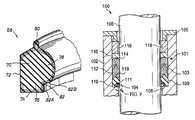
- FIG. 1depicts a typical homogeneous elastomeric header ring shown as 10 .
- header ring 10is made of a homogeneous elastomeric material and comprises an annular body portion 12 .
- Header ring 10includes a forwardly facing, annularly extending planar surface 20 , an annularly extending, radially outwardly facing cylindrical surface 22 , an annularly extending, radially inwardly facing cylindrical surface 24 and a radially inwardly facing convex sealing surface 26 , surfaces 24 and 26 being adjoined at an annularly extending juncture 28 .
- the header ring 10is shown after use and after a portion of the header ring has been nibbled out.
- the nibbled out area indicated at 30comprises a portion of header ring 10 formed by intersecting surfaces 24 and 26 . More specifically, it can be seen that the juncture 28 shown in FIG. 1 between surfaces 24 and 26 has been gouged out due to the nibbling effect.
- FIGS. 3 and 4depict another prior art header ring, FIG. 3 depicting the header ring in its original or undamaged state, FIG. 4 depicting the header ring of FIG. 3 following use and damage as a result of nibbling.
- the header ring 10 A shown in FIG. 3has a body portion 32 comprised of first body section 34 and second body section 36 .
- Section 36 of body portion 32comprises a fabric or fiber reinforced material while portion 34 is formed of a homogeneous elastomeric material construction.
- FIG. 4shows the header ring 10 A of FIG. 3 which has been damaged due to nibbling and once again the nibbling has occurred at the juncture 46 between radially inwardly facing cylindrical wall 43 and radially inwardly facing surface 45 .
- the present inventionprovides a header ring for use in a packing or seal assembly between a reciprocating, cylindrical member and a cylindrical wall of a housing in which the cylindrical member reciprocates.
- the header ring of the present inventionhas an annularly extending body portion, at least a portion of which comprises an elastomeric material, an annular pedestal portion formed on said body and having an annular, radially inwardly facing pedestal surface, a radially inwardly facing, annularly extending sealing lip formed on said body and having a radially inwardly facing sealing surface, at least a portion of the pedestal portion forming the pedestal surface and an at least a portion of the sealing lip forming at least a portion of the sealing surface being comprised of a layer of fabric reinforced elastomeric material.
- a sealing assemblyfor sealing between a cylindrical movable member and a housing having a cylindrical bore in which the cylindrical member reciprocates, the sealing assembly including a header ring as described above.
- FIG. 1is a cross-sectional view of a prior art header ring prior to installation.
- FIG. 2is a cross-sectional view of the header ring of FIG. 1 which has been damaged by nibbling.
- FIG. 3is a cross-sectional view of another type of prior art header ring prior to installation.
- FIG. 4is a cross-sectional view of the header ring of FIG. 3 which has been damaged by nibbling.
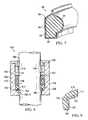
- FIG. 5is a cross-sectional view of one embodiment of the header ring of the present invention.
- FIG. 6is a cross-sectional view of another embodiment of the header ring of the present invention.
- FIG. 7is a cross-sectional view of another embodiment of the header ring of the present invention.
- FIG. 8is a schematic view, partly in section, of a sealing assembly according to the present invention in the stuffing box of a plunger pump.
- FIG. 9is an enlarged view of the circled portion of the header ring shown in FIG. 8 .
- the header ring 50comprises an annular body portion 52 , an annular axially extending pedestal 53 , an annular, axially extending bead 56 , distal the pedestal 53 , and a radially inwardly facing, annularly extending sealing lip 58 .
- body 52 , bead 56 , pedestal 53 and sealing lip 58are integrally formed, for the most part, of a homogeneous, elastomeric material.
- a portion 60 of the pedestal 53 forming the radially inwardly facing cylindrical surface 61 and the portion 62 of the sealing lip 58 forming a portion of sealing surface 64is comprised of a layer of reinforced, elastomeric material, bonded to the homogeneous elastomeric material of the remainder of header ring 50 .
- the portions 60 and 62extend over the juncture 63 of surfaces 61 and 64 .
- the fabric reinforced sections 60 and 62when adjoined, are generally L-shaped when viewed in transverse cross-section.
- FIG. 6shows another embodiment of the present invention wherein the header ring 68 has an annular body portion 70 which is primarily made of a homogeneous elastomeric material.
- the header ring 68has an annular, radially outwardly facing cylindrical surface 72 .
- Bonded to the homogeneous elastomeric portion of body 70is an annular layer 74 of a fabric reinforced elastomer, the layer 74 covering the surfaces of the pedestal 76 , the sealing lip 78 , the bead 80 and portions of the forward and rearward portions of the body 70 forming surface 72 .
- the portions of the pedestal 76 and sealing lip 78 forming juncture 82 between the pedestal 76 and the sealing lip 78is formed of a layer of fabric reinforced elastomeric material forming adjoining surfaces 82 A and 82 B.
- FIG. 7there is shown another embodiment of the present invention, wherein the header ring, shown generally as 88 , has a body 89 , the core 90 of which is comprised of an elastomeric material, a portion of annular pedestal 92 and a portion of annular sealing lip 94 .
- the reinforced fabric layer 96completely encapsulates or surrounds the core 90 of body portion 89 .
- FIG. 8depicts a typical sealing assembly 101 for use in a stuffing box, shown generally as 100 , of a plunger-type pump employing a header ring of the present invention.
- Stuffing box 100comprises a housing 102 having a bore 104 extending therethrough, bore 104 defining a cylindrical surface 103 .
- Housing 102also has a shoulder portion 108 .
- Movably, e.g., reciprocally, positioned in bore 104is a plunger, piston or shaft 106 .
- Sealing assembly 101comprises an annular gland 105 , an annular header ring 110 , an-annular, first seal ring 112 , and an annular, second seal ring 114 .
- the sealing assembly 101also includes a top, annular adaptor ring 116 and an annular bushing 118 .
- header ring 110forms a wiper ring at the high pressure end of the sealing assembly 101 , its primary function being to prevent abrasives/solids from entering the region where the seal rings 112 and 114 are positioned and thereby prevent excessive wear on seal rings 112 and 114 . It is also to be noted that, as shown in FIG. 8 , header ring 110 no longer has the shape shown in, for example, FIG.
- header ring 110is constructed essentially the same as the header ring shown in FIG. 5 having a generally L-shaped, annularly extending reinforcing section or layer 120 that bridges the juncture 122 between the surface of sealing lip 124 and the surface of pedestal 126 .
- packing assembly 101has been shown as containing two seal rings of the chevron or V-shaped type, it will be appreciated that depending upon the use to which the plunger pump is subjected, fewer or more sealing rings can be employed. It will also be seen that the annular bead 119 of header ring 110 is nested in the annularly extending, axially facing groove in seal ring 112 so as to anchor seal ring 112 to the header ring 110 . It will be appreciated that the seal rings 112 and 114 can be constructed of various materials and have various shapes, the only provision being that they have sufficient resiliency to effect sealing between the housing 102 and plunger 106 . Generally speaking, components such as annular bushing 118 , top adaptor 116 , and annular gland 105 are made of a metallic material, e.g., brass.
- the packing assembly 101can be energized by header ring 110 and can be made to be adjustable by techniques well known in the art. If, however the packing assembly 101 is preloaded, care must be taken to ensure that the correct amount of preload is employed to prevent movement of the sealing assembly in the housing or stuffing box to prevent excessive wear on the sealing assembly. In this regard, if there is too little preload the packing will move in the housing wearing both the ID and OD of the seal rings as well as the header ring causing premature wear and in extreme cases causing wear in the stuffing box resulting in expensive repair or refurbishment. On the other hand, if the packing assembly is adjusted with too little preload, high friction forces cause accelerated wear of the header ring and the seal rings with premature failure.
- the homogeneous elastomeric core of the header ring of the present inventioncan be made from a number of different natural or synthetic rubbers as, for example, nitrile or butadiene rubber, with a desired degree of hardness again depending upon the use to which the plunger pump is exposed.
- the elastomeric portions of the seal rings 112 and 114can be of various rubbers with desirable hardness.
- the seal rings, e.g., seal rings 112 and 114can be reinforced with fabric, can be homogeneous elastomeric materials, can have anti-extrusion portions, etc.
- Sections 61 and 62 forming an anti-nibbling sectionare generally a fabric reinforced rubber, synthetic or natural.
- fabric as used with respect to the anti-nibbling wear section of the various embodiments of the present inventionis used in the broadest sense and includes any cloth or cloth-like structure made by any technique such as knitting, weaving or felting of fibers of natural or synthetic materials as well as mixed fibers and includes, without limitation, fibers of cotton, nylon, polyester, polyester blends, aramid fibers, fiberglass fibers or any combination thereof.
Landscapes
- Engineering & Computer Science (AREA)
- General Engineering & Computer Science (AREA)
- Mechanical Engineering (AREA)
- Sealing Devices (AREA)
- Details Of Reciprocating Pumps (AREA)
Abstract
Description
Claims (13)
Priority Applications (5)
| Application Number | Priority Date | Filing Date | Title |
|---|---|---|---|
| US14/459,869US9534691B2 (en) | 2008-01-02 | 2014-08-14 | Packing assembly for a pump |
| US15/370,625US10428949B2 (en) | 2008-01-02 | 2016-12-06 | Packing assembly for a pump |
| US16/444,999US11300206B2 (en) | 2008-01-02 | 2019-06-18 | Packing assembly for a pump |
| US17/457,204US20220112953A1 (en) | 2008-01-02 | 2021-12-01 | Packing Assembly for a Pump |
| US18/376,443US20240026976A1 (en) | 2008-01-02 | 2023-10-04 | Starter ring for reciprocating plunger pump |
Applications Claiming Priority (5)
| Application Number | Priority Date | Filing Date | Title |
|---|---|---|---|
| US1853808P | 2008-01-02 | 2008-01-02 | |
| US12/347,207US20090166980A1 (en) | 2008-01-02 | 2008-12-31 | Packing assembly for a pump |
| US13/440,585US20120210868A1 (en) | 2008-01-02 | 2012-04-05 | Packing assembly for a pump |
| US13/954,672US20130330220A1 (en) | 2008-01-02 | 2013-07-30 | Packing assembly for a pump |
| US14/459,869US9534691B2 (en) | 2008-01-02 | 2014-08-14 | Packing assembly for a pump |
Related Parent Applications (1)
| Application Number | Title | Priority Date | Filing Date |
|---|---|---|---|
| US13/954,672ContinuationUS20130330220A1 (en) | 2008-01-02 | 2013-07-30 | Packing assembly for a pump |
Related Child Applications (2)
| Application Number | Title | Priority Date | Filing Date |
|---|---|---|---|
| US15/370,625ContinuationUS10428949B2 (en) | 2008-01-02 | 2016-12-06 | Packing assembly for a pump |
| US18/376,443ContinuationUS20240026976A1 (en) | 2008-01-02 | 2023-10-04 | Starter ring for reciprocating plunger pump |
Publications (2)
| Publication Number | Publication Date |
|---|---|
| US20150377356A1 US20150377356A1 (en) | 2015-12-31 |
| US9534691B2true US9534691B2 (en) | 2017-01-03 |
Family
ID=40797239
Family Applications (8)
| Application Number | Title | Priority Date | Filing Date |
|---|---|---|---|
| US12/347,207AbandonedUS20090166980A1 (en) | 2008-01-02 | 2008-12-31 | Packing assembly for a pump |
| US13/440,585AbandonedUS20120210868A1 (en) | 2008-01-02 | 2012-04-05 | Packing assembly for a pump |
| US13/954,672AbandonedUS20130330220A1 (en) | 2008-01-02 | 2013-07-30 | Packing assembly for a pump |
| US14/459,869Active2030-01-28US9534691B2 (en) | 2008-01-02 | 2014-08-14 | Packing assembly for a pump |
| US15/370,625Active2029-06-18US10428949B2 (en) | 2008-01-02 | 2016-12-06 | Packing assembly for a pump |
| US16/444,999ActiveUS11300206B2 (en) | 2008-01-02 | 2019-06-18 | Packing assembly for a pump |
| US17/457,204AbandonedUS20220112953A1 (en) | 2008-01-02 | 2021-12-01 | Packing Assembly for a Pump |
| US18/376,443PendingUS20240026976A1 (en) | 2008-01-02 | 2023-10-04 | Starter ring for reciprocating plunger pump |
Family Applications Before (3)
| Application Number | Title | Priority Date | Filing Date |
|---|---|---|---|
| US12/347,207AbandonedUS20090166980A1 (en) | 2008-01-02 | 2008-12-31 | Packing assembly for a pump |
| US13/440,585AbandonedUS20120210868A1 (en) | 2008-01-02 | 2012-04-05 | Packing assembly for a pump |
| US13/954,672AbandonedUS20130330220A1 (en) | 2008-01-02 | 2013-07-30 | Packing assembly for a pump |
Family Applications After (4)
| Application Number | Title | Priority Date | Filing Date |
|---|---|---|---|
| US15/370,625Active2029-06-18US10428949B2 (en) | 2008-01-02 | 2016-12-06 | Packing assembly for a pump |
| US16/444,999ActiveUS11300206B2 (en) | 2008-01-02 | 2019-06-18 | Packing assembly for a pump |
| US17/457,204AbandonedUS20220112953A1 (en) | 2008-01-02 | 2021-12-01 | Packing Assembly for a Pump |
| US18/376,443PendingUS20240026976A1 (en) | 2008-01-02 | 2023-10-04 | Starter ring for reciprocating plunger pump |
Country Status (1)
| Country | Link |
|---|---|
| US (8) | US20090166980A1 (en) |
Cited By (29)
| Publication number | Priority date | Publication date | Assignee | Title |
|---|---|---|---|---|
| US20170082199A1 (en)* | 2008-01-02 | 2017-03-23 | Utex Industries, Inc. | Packing Assembly for a Pump |
| WO2019108249A1 (en)* | 2017-12-01 | 2019-06-06 | Gardner Denver Petroleum Pumps Llc | Header ring |
| USD893684S1 (en)* | 2017-08-22 | 2020-08-18 | Garlock Sealing Technologies, Llc | Header ring for a reciprocating stem or piston rod |
| USD895777S1 (en) | 2017-09-20 | 2020-09-08 | Gardner Denver Petroleum Pumps Llc | Header ring |
| US10837556B2 (en) | 2017-09-20 | 2020-11-17 | Fardner Denver Petroleum Pumps Llc | Packing for a well service pump |
| US11143305B1 (en) | 2017-08-22 | 2021-10-12 | Garlock Sealing Technologies, Llc | Hydraulic components and methods of manufacturing |
| US11353117B1 (en) | 2020-01-17 | 2022-06-07 | Vulcan Industrial Holdings, LLC | Valve seat insert system and method |
| US11384756B1 (en) | 2020-08-19 | 2022-07-12 | Vulcan Industrial Holdings, LLC | Composite valve seat system and method |
| US11391374B1 (en) | 2021-01-14 | 2022-07-19 | Vulcan Industrial Holdings, LLC | Dual ring stuffing box |
| US11421680B1 (en) | 2020-06-30 | 2022-08-23 | Vulcan Industrial Holdings, LLC | Packing bore wear sleeve retainer system |
| US11421679B1 (en) | 2020-06-30 | 2022-08-23 | Vulcan Industrial Holdings, LLC | Packing assembly with threaded sleeve for interaction with an installation tool |
| US11434900B1 (en) | 2022-04-25 | 2022-09-06 | Vulcan Industrial Holdings, LLC | Spring controlling valve |
| USD980876S1 (en) | 2020-08-21 | 2023-03-14 | Vulcan Industrial Holdings, LLC | Fluid end for a pumping system |
| USD986928S1 (en) | 2020-08-21 | 2023-05-23 | Vulcan Industrial Holdings, LLC | Fluid end for a pumping system |
| US20230184238A1 (en)* | 2020-04-13 | 2023-06-15 | Spm Oil & Gas Inc. | Pumping system having remote valve blocks |
| US11692544B2 (en) | 2020-11-20 | 2023-07-04 | Gd Energy Products, Llc | Scraper ring assembly |
| US11692543B2 (en) | 2020-11-20 | 2023-07-04 | Gd Energy Products, Llc | Scraper ring |
| USD997992S1 (en) | 2020-08-21 | 2023-09-05 | Vulcan Industrial Holdings, LLC | Fluid end for a pumping system |
| US11920684B1 (en) | 2022-05-17 | 2024-03-05 | Vulcan Industrial Holdings, LLC | Mechanically or hybrid mounted valve seat |
| US12018676B2 (en) | 2020-11-20 | 2024-06-25 | Gd Energy Products, Llc | Scraper ring assembly |
| US12049889B2 (en) | 2020-06-30 | 2024-07-30 | Vulcan Industrial Holdings, LLC | Packing bore wear sleeve retainer system |
| US12055221B2 (en) | 2021-01-14 | 2024-08-06 | Vulcan Industrial Holdings, LLC | Dual ring stuffing box |
| US12140240B1 (en) | 2022-01-19 | 2024-11-12 | Vulcan Industrial Holdings, LLC | Gradient material structures and methods of forming the same |
| USD1061623S1 (en) | 2022-08-03 | 2025-02-11 | Vulcan Industrial Holdings, LLC | Fluid end for a pumping system |
| US12292120B1 (en) | 2021-02-23 | 2025-05-06 | Vulcan Industrial Holdings, LLC | System and method for valve assembly |
| US12292121B2 (en) | 2023-08-10 | 2025-05-06 | Vulcan Industrial Holdings, LLC | Valve member including cavity, and related assemblies, systems, and methods |
| US12297922B1 (en) | 2022-03-04 | 2025-05-13 | Vulcan Industrial Holdings, LLC | Valve seat with embedded structure and related methods |
| US12345332B2 (en) | 2021-08-18 | 2025-07-01 | Vulcan Industrial Holdings, LLC | Self-locking plug |
| US12366245B1 (en) | 2020-08-27 | 2025-07-22 | Vulcan Industrial Holdings, LLC | Connecting rod assembly for reciprocating pump |
Families Citing this family (9)
| Publication number | Priority date | Publication date | Assignee | Title |
|---|---|---|---|---|
| US8616555B2 (en)* | 2008-10-13 | 2013-12-31 | Schlumberger Technology Corporation | Packing assembly for reciprocating pumps |
| US9845801B1 (en)* | 2012-01-03 | 2017-12-19 | FAST Group-Houston, Inc. | Header ring for reciprocating pump |
| US9016693B1 (en) | 2012-01-25 | 2015-04-28 | FAST Group-Houston Inc. | Packing seal for reciprocating pump |
| CN104500383B (en)* | 2014-11-20 | 2017-07-11 | 徐承韬 | A kind of plunger pump sealing apparatus |
| US10077669B2 (en) | 2014-11-26 | 2018-09-18 | United Technologies Corporation | Non-metallic engine case inlet compression seal for a gas turbine engine |
| MX2019011830A (en)* | 2017-04-06 | 2019-11-07 | Ocv Intellectual Capital Llc | Reinforcement fibers with improved stiffness. |
| CN110671500A (en)* | 2019-09-20 | 2020-01-10 | 广州加士特密封技术有限公司 | Plunger fracturing pump sealing washer |
| US11698063B2 (en)* | 2020-05-15 | 2023-07-11 | American Jereh International Corporation | Hydraulic end assembly structure of a plunger pump |
| WO2024081856A2 (en)* | 2022-10-13 | 2024-04-18 | Checkpoint Group, Inc. | Self-maintaining seals, pumps including the same, and related methods |
Citations (43)
| Publication number | Priority date | Publication date | Assignee | Title |
|---|---|---|---|---|
| US2953398A (en) | 1956-05-28 | 1960-09-20 | United States Pipe Foundry | Pipe joint |
| US3013830A (en) | 1958-06-27 | 1961-12-19 | Garlock Inc | Packing |
| US3419280A (en) | 1965-03-22 | 1968-12-31 | John H. Wheeler | Preloaded fluid packing assembly and male adapter |
| US4138144A (en) | 1977-04-26 | 1979-02-06 | Nl Industries, Inc. | Wellhead sealing assembly |
| US4310163A (en) | 1980-01-10 | 1982-01-12 | Utex Industries, Inc. | Anti-extrusion seals and packings |
| US4440404A (en) | 1982-08-09 | 1984-04-03 | Halliburton Company | Packing arrangement |
| US4510994A (en) | 1984-04-06 | 1985-04-16 | Camco, Incorporated | Pump out sub |
| US4729432A (en) | 1987-04-29 | 1988-03-08 | Halliburton Company | Activation mechanism for differential fill floating equipment |
| US4823882A (en) | 1988-06-08 | 1989-04-25 | Tam International, Inc. | Multiple-set packer and method |
| US4848463A (en) | 1988-11-09 | 1989-07-18 | Halliburton Company | Surface read-out tester valve and probe |
| US4893678A (en) | 1988-06-08 | 1990-01-16 | Tam International | Multiple-set downhole tool and method |
| US5462121A (en) | 1994-05-03 | 1995-10-31 | Baker Hughes Incorporated | Failsafe liner installation assembly and method |
| US5960700A (en) | 1998-08-26 | 1999-10-05 | National-Oilwell, L.P. | Replaceable mud pump piston seal |
| WO2001006086A1 (en) | 1999-07-15 | 2001-01-25 | Andrew Philip Churchill | Downhole bypass valve |
| US6817228B2 (en) | 2002-04-01 | 2004-11-16 | Schlumberger Technology Corporation | Method and apparatus for detecting seal failure |
| US6907936B2 (en) | 2001-11-19 | 2005-06-21 | Packers Plus Energy Services Inc. | Method and apparatus for wellbore fluid treatment |
| US7108067B2 (en) | 2002-08-21 | 2006-09-19 | Packers Plus Energy Services Inc. | Method and apparatus for wellbore fluid treatment |
| US20060213670A1 (en) | 2003-02-24 | 2006-09-28 | Bj Services Company | Bi-directional ball seat system and method |
| US7124824B2 (en) | 2000-12-05 | 2006-10-24 | Bj Services Company, U.S.A. | Washpipeless isolation strings and methods for isolation |
| US20070017679A1 (en) | 2005-06-30 | 2007-01-25 | Wolf John C | Downhole multi-action jetting tool |
| US20070278017A1 (en) | 2006-05-30 | 2007-12-06 | Smith International, Inc. | Rolling cutter |
| US7322417B2 (en) | 2004-12-14 | 2008-01-29 | Schlumberger Technology Corporation | Technique and apparatus for completing multiple zones |
| US20080066924A1 (en) | 2006-09-18 | 2008-03-20 | Baker Hughes Incorporated | Retractable ball seat having a time delay material |
| US7503392B2 (en) | 2007-08-13 | 2009-03-17 | Baker Hughes Incorporated | Deformable ball seat |
| US7628210B2 (en) | 2007-08-13 | 2009-12-08 | Baker Hughes Incorporated | Ball seat having ball support member |
| US20090308588A1 (en) | 2008-06-16 | 2009-12-17 | Halliburton Energy Services, Inc. | Method and Apparatus for Exposing a Servicing Apparatus to Multiple Formation Zones |
| US7644772B2 (en) | 2007-08-13 | 2010-01-12 | Baker Hughes Incorporated | Ball seat having segmented arcuate ball support member |
| US7681650B2 (en) | 2004-04-30 | 2010-03-23 | Specialised Petroleum Services Group Limited | Valve seat |
| WO2011117602A2 (en) | 2010-03-26 | 2011-09-29 | Colin Smith | Mechanical counter |
| US20110278017A1 (en) | 2009-05-07 | 2011-11-17 | Packers Plus Energy Services Inc. | Sliding sleeve sub and method and apparatus for wellbore fluid treatment |
| US20120048556A1 (en) | 2010-08-24 | 2012-03-01 | Baker Hughes Incorporated | Plug counter, fracing system and method |
| US8215401B2 (en) | 2010-02-12 | 2012-07-10 | I-Tec As | Expandable ball seat |
| US8261761B2 (en) | 2009-05-07 | 2012-09-11 | Baker Hughes Incorporated | Selectively movable seat arrangement and method |
| US8356670B2 (en) | 2007-03-31 | 2013-01-22 | Specialised Petroleum Services Group Limited | Ball seat assembly and method of controlling fluid flow through a hollow body |
| US20130068475A1 (en) | 2011-03-16 | 2013-03-21 | Raymond Hofman | Multistage Production System Incorporating Valve Assembly With Collapsible or Expandable C-Ring |
| US20130118732A1 (en) | 2011-03-02 | 2013-05-16 | Team Oil Tools, Lp | Multi-actuating seat and drop element |
| US20130133876A1 (en) | 2011-11-14 | 2013-05-30 | Utex Industries, Inc. | Seat assembly for isolating fracture zones in a well |
| US8479822B2 (en) | 2010-02-08 | 2013-07-09 | Summit Downhole Dynamics, Ltd | Downhole tool with expandable seat |
| US8479823B2 (en) | 2009-09-22 | 2013-07-09 | Baker Hughes Incorporated | Plug counter and method |
| US8540019B2 (en) | 2010-10-21 | 2013-09-24 | Summit Downhole Dynamics, Ltd | Fracturing system and method |
| US20130248201A1 (en) | 2012-03-20 | 2013-09-26 | Team Oil Tools, Lp | Method and apparatus for actuating a downhole tool |
| US20130333891A1 (en) | 2012-06-14 | 2013-12-19 | Halliburton Energy Services, Inc. | Wellbore isolation device containing a substance that undergoes a phase transition |
| US8783365B2 (en) | 2011-07-28 | 2014-07-22 | Baker Hughes Incorporated | Selective hydraulic fracturing tool and method thereof |
Family Cites Families (20)
| Publication number | Priority date | Publication date | Assignee | Title |
|---|---|---|---|---|
| US1313320A (en) | 1919-08-19 | Miller | ||
| US1372529A (en) | 1920-05-27 | 1921-03-22 | Charles I E Mastin | Packing and method of making same |
| US2212291A (en) | 1936-07-29 | 1940-08-20 | Victor Mfg And Gasket Company | Fluid seal with gripped fabric faced packing |
| US2442687A (en) | 1945-07-13 | 1948-06-01 | Universal Packing & Gasket Com | Packing for stuffing boxes |
| US2658809A (en) | 1948-05-17 | 1953-11-10 | Edward H Schultz | Hydraulic fluid seal |
| US2819102A (en) | 1952-09-10 | 1958-01-07 | Raybestos Manhattan Inc | Seal for packing rings in a stuffing box |
| US2907614A (en) | 1958-02-25 | 1959-10-06 | Rosen Sidney | Precision pump |
| US3094337A (en) | 1960-10-31 | 1963-06-18 | Universal Packing & Gasket Com | Seal ring |
| US3120960A (en) | 1960-12-15 | 1964-02-11 | Universal Packing & Gasket Com | Packing ring with load bearing body and process for making same |
| US3271039A (en) | 1962-03-29 | 1966-09-06 | Kohl | Packing ring and method of making |
| US3719366A (en) | 1971-05-26 | 1973-03-06 | Utex Ind Inc | Heterogeneous lip-type packings |
| US4219204A (en) | 1978-11-30 | 1980-08-26 | Utex Industries, Inc. | Anti-extrusion seals and packings |
| US4474382A (en) | 1984-02-21 | 1984-10-02 | Halliburton Company | Unitized seal carrier assembly for reciprocating shaft |
| US5738358A (en) | 1996-01-02 | 1998-04-14 | Kalsi Engineering, Inc. | Extrusion resistant hydrodynamically lubricated multiple modulus rotary shaft seal |
| US6561520B2 (en)* | 2000-02-02 | 2003-05-13 | Kalsi Engineering, Inc. | Hydrodynamic rotary coupling seal |
| US20090166980A1 (en)* | 2008-01-02 | 2009-07-02 | Miller John A | Packing assembly for a pump |
| US9845801B1 (en)* | 2012-01-03 | 2017-12-19 | FAST Group-Houston, Inc. | Header ring for reciprocating pump |
| US10837556B2 (en)* | 2017-09-20 | 2020-11-17 | Fardner Denver Petroleum Pumps Llc | Packing for a well service pump |
| CA3143999A1 (en)* | 2019-06-19 | 2020-12-24 | Spm Oil & Gas Inc. | Moveable seal point packing system |
| US20220034402A1 (en)* | 2020-07-30 | 2022-02-03 | Vulcan Industrial Holdings, LLC | Composite pump packing sealing elements |
- 2008
- 2008-12-31USUS12/347,207patent/US20090166980A1/ennot_activeAbandoned
- 2012
- 2012-04-05USUS13/440,585patent/US20120210868A1/ennot_activeAbandoned
- 2013
- 2013-07-30USUS13/954,672patent/US20130330220A1/ennot_activeAbandoned
- 2014
- 2014-08-14USUS14/459,869patent/US9534691B2/enactiveActive
- 2016
- 2016-12-06USUS15/370,625patent/US10428949B2/enactiveActive
- 2019
- 2019-06-18USUS16/444,999patent/US11300206B2/enactiveActive
- 2021
- 2021-12-01USUS17/457,204patent/US20220112953A1/ennot_activeAbandoned
- 2023
- 2023-10-04USUS18/376,443patent/US20240026976A1/enactivePending
Patent Citations (50)
| Publication number | Priority date | Publication date | Assignee | Title |
|---|---|---|---|---|
| US2953398A (en) | 1956-05-28 | 1960-09-20 | United States Pipe Foundry | Pipe joint |
| US3013830A (en) | 1958-06-27 | 1961-12-19 | Garlock Inc | Packing |
| US3419280A (en) | 1965-03-22 | 1968-12-31 | John H. Wheeler | Preloaded fluid packing assembly and male adapter |
| US4138144A (en) | 1977-04-26 | 1979-02-06 | Nl Industries, Inc. | Wellhead sealing assembly |
| US4310163A (en) | 1980-01-10 | 1982-01-12 | Utex Industries, Inc. | Anti-extrusion seals and packings |
| US4440404A (en) | 1982-08-09 | 1984-04-03 | Halliburton Company | Packing arrangement |
| US4510994A (en) | 1984-04-06 | 1985-04-16 | Camco, Incorporated | Pump out sub |
| US4729432A (en) | 1987-04-29 | 1988-03-08 | Halliburton Company | Activation mechanism for differential fill floating equipment |
| US4893678A (en) | 1988-06-08 | 1990-01-16 | Tam International | Multiple-set downhole tool and method |
| US4823882A (en) | 1988-06-08 | 1989-04-25 | Tam International, Inc. | Multiple-set packer and method |
| US4848463A (en) | 1988-11-09 | 1989-07-18 | Halliburton Company | Surface read-out tester valve and probe |
| US5462121A (en) | 1994-05-03 | 1995-10-31 | Baker Hughes Incorporated | Failsafe liner installation assembly and method |
| US5960700A (en) | 1998-08-26 | 1999-10-05 | National-Oilwell, L.P. | Replaceable mud pump piston seal |
| WO2001006086A1 (en) | 1999-07-15 | 2001-01-25 | Andrew Philip Churchill | Downhole bypass valve |
| US7124824B2 (en) | 2000-12-05 | 2006-10-24 | Bj Services Company, U.S.A. | Washpipeless isolation strings and methods for isolation |
| US7861774B2 (en) | 2001-11-19 | 2011-01-04 | Packers Plus Energy Services Inc. | Method and apparatus for wellbore fluid treatment |
| US6907936B2 (en) | 2001-11-19 | 2005-06-21 | Packers Plus Energy Services Inc. | Method and apparatus for wellbore fluid treatment |
| US7543634B2 (en) | 2001-11-19 | 2009-06-09 | Packers Plus Energy Services Inc. | Method and apparatus for wellbore fluid treatment |
| US8397820B2 (en) | 2001-11-19 | 2013-03-19 | Packers Plus Energy Services Inc. | Method and apparatus for wellbore fluid treatment |
| US7134505B2 (en) | 2001-11-19 | 2006-11-14 | Packers Plus Energy Services Inc. | Method and apparatus for wellbore fluid treatment |
| US6817228B2 (en) | 2002-04-01 | 2004-11-16 | Schlumberger Technology Corporation | Method and apparatus for detecting seal failure |
| US7108067B2 (en) | 2002-08-21 | 2006-09-19 | Packers Plus Energy Services Inc. | Method and apparatus for wellbore fluid treatment |
| US20060213670A1 (en) | 2003-02-24 | 2006-09-28 | Bj Services Company | Bi-directional ball seat system and method |
| US7681650B2 (en) | 2004-04-30 | 2010-03-23 | Specialised Petroleum Services Group Limited | Valve seat |
| US7322417B2 (en) | 2004-12-14 | 2008-01-29 | Schlumberger Technology Corporation | Technique and apparatus for completing multiple zones |
| US7377321B2 (en) | 2004-12-14 | 2008-05-27 | Schlumberger Technology Corporation | Testing, treating, or producing a multi-zone well |
| US20070017679A1 (en) | 2005-06-30 | 2007-01-25 | Wolf John C | Downhole multi-action jetting tool |
| US20070278017A1 (en) | 2006-05-30 | 2007-12-06 | Smith International, Inc. | Rolling cutter |
| US20080066924A1 (en) | 2006-09-18 | 2008-03-20 | Baker Hughes Incorporated | Retractable ball seat having a time delay material |
| US8356670B2 (en) | 2007-03-31 | 2013-01-22 | Specialised Petroleum Services Group Limited | Ball seat assembly and method of controlling fluid flow through a hollow body |
| US7503392B2 (en) | 2007-08-13 | 2009-03-17 | Baker Hughes Incorporated | Deformable ball seat |
| US7628210B2 (en) | 2007-08-13 | 2009-12-08 | Baker Hughes Incorporated | Ball seat having ball support member |
| US7644772B2 (en) | 2007-08-13 | 2010-01-12 | Baker Hughes Incorporated | Ball seat having segmented arcuate ball support member |
| US20090308588A1 (en) | 2008-06-16 | 2009-12-17 | Halliburton Energy Services, Inc. | Method and Apparatus for Exposing a Servicing Apparatus to Multiple Formation Zones |
| US20110278017A1 (en) | 2009-05-07 | 2011-11-17 | Packers Plus Energy Services Inc. | Sliding sleeve sub and method and apparatus for wellbore fluid treatment |
| US8261761B2 (en) | 2009-05-07 | 2012-09-11 | Baker Hughes Incorporated | Selectively movable seat arrangement and method |
| US8479823B2 (en) | 2009-09-22 | 2013-07-09 | Baker Hughes Incorporated | Plug counter and method |
| US8479822B2 (en) | 2010-02-08 | 2013-07-09 | Summit Downhole Dynamics, Ltd | Downhole tool with expandable seat |
| US8215401B2 (en) | 2010-02-12 | 2012-07-10 | I-Tec As | Expandable ball seat |
| WO2011117602A2 (en) | 2010-03-26 | 2011-09-29 | Colin Smith | Mechanical counter |
| US8789600B2 (en) | 2010-08-24 | 2014-07-29 | Baker Hughes Incorporated | Fracing system and method |
| US8668013B2 (en) | 2010-08-24 | 2014-03-11 | Baker Hughes Incorporated | Plug counter, fracing system and method |
| US20120048556A1 (en) | 2010-08-24 | 2012-03-01 | Baker Hughes Incorporated | Plug counter, fracing system and method |
| US8540019B2 (en) | 2010-10-21 | 2013-09-24 | Summit Downhole Dynamics, Ltd | Fracturing system and method |
| US20130118732A1 (en) | 2011-03-02 | 2013-05-16 | Team Oil Tools, Lp | Multi-actuating seat and drop element |
| US20130068475A1 (en) | 2011-03-16 | 2013-03-21 | Raymond Hofman | Multistage Production System Incorporating Valve Assembly With Collapsible or Expandable C-Ring |
| US8783365B2 (en) | 2011-07-28 | 2014-07-22 | Baker Hughes Incorporated | Selective hydraulic fracturing tool and method thereof |
| US20130133876A1 (en) | 2011-11-14 | 2013-05-30 | Utex Industries, Inc. | Seat assembly for isolating fracture zones in a well |
| US20130248201A1 (en) | 2012-03-20 | 2013-09-26 | Team Oil Tools, Lp | Method and apparatus for actuating a downhole tool |
| US20130333891A1 (en) | 2012-06-14 | 2013-12-19 | Halliburton Energy Services, Inc. | Wellbore isolation device containing a substance that undergoes a phase transition |
Non-Patent Citations (2)
| Title |
|---|
| Office Action mailed Dec. 12, 2011, by the USPTO, regarding U.S. Appl. No. 12/347,207, 8 pages. |
| Office Action mailed Sep. 20, 2011, by the USPTO, regarding U.S. Appl. No. 12/347,207, 10 pages. |
Cited By (40)
| Publication number | Priority date | Publication date | Assignee | Title |
|---|---|---|---|---|
| US11300206B2 (en)* | 2008-01-02 | 2022-04-12 | Utex Industries, Inc. | Packing assembly for a pump |
| US20170082199A1 (en)* | 2008-01-02 | 2017-03-23 | Utex Industries, Inc. | Packing Assembly for a Pump |
| US10428949B2 (en)* | 2008-01-02 | 2019-10-01 | Utex Industries, Inc. | Packing assembly for a pump |
| US20190323608A1 (en)* | 2008-01-02 | 2019-10-24 | Utex Industries, Inc. | Packing Assembly for a Pump |
| US20240026976A1 (en)* | 2008-01-02 | 2024-01-25 | Robert Henry Ash | Starter ring for reciprocating plunger pump |
| USD893684S1 (en)* | 2017-08-22 | 2020-08-18 | Garlock Sealing Technologies, Llc | Header ring for a reciprocating stem or piston rod |
| US11635145B1 (en) | 2017-08-22 | 2023-04-25 | Garlock Sealing Technologies, Llc | Hydraulic components and methods of manufacturing |
| US11143305B1 (en) | 2017-08-22 | 2021-10-12 | Garlock Sealing Technologies, Llc | Hydraulic components and methods of manufacturing |
| USD895777S1 (en) | 2017-09-20 | 2020-09-08 | Gardner Denver Petroleum Pumps Llc | Header ring |
| US10837556B2 (en) | 2017-09-20 | 2020-11-17 | Fardner Denver Petroleum Pumps Llc | Packing for a well service pump |
| WO2019108249A1 (en)* | 2017-12-01 | 2019-06-06 | Gardner Denver Petroleum Pumps Llc | Header ring |
| US11353117B1 (en) | 2020-01-17 | 2022-06-07 | Vulcan Industrial Holdings, LLC | Valve seat insert system and method |
| US12385479B2 (en)* | 2020-04-13 | 2025-08-12 | Spm Oil & Gas Inc. | Pumping system having remote valve blocks |
| US20230184238A1 (en)* | 2020-04-13 | 2023-06-15 | Spm Oil & Gas Inc. | Pumping system having remote valve blocks |
| US11421680B1 (en) | 2020-06-30 | 2022-08-23 | Vulcan Industrial Holdings, LLC | Packing bore wear sleeve retainer system |
| US12270394B2 (en) | 2020-06-30 | 2025-04-08 | Vulcan Industrial Holdings, LLC | Packing bore wear sleeve retainer system |
| US12345253B2 (en) | 2020-06-30 | 2025-07-01 | Vulcan Industrial Holdings, LLC | Packing assembly with threaded sleeve for interaction with an installation tool |
| US12049889B2 (en) | 2020-06-30 | 2024-07-30 | Vulcan Industrial Holdings, LLC | Packing bore wear sleeve retainer system |
| US11421679B1 (en) | 2020-06-30 | 2022-08-23 | Vulcan Industrial Holdings, LLC | Packing assembly with threaded sleeve for interaction with an installation tool |
| US11384756B1 (en) | 2020-08-19 | 2022-07-12 | Vulcan Industrial Holdings, LLC | Composite valve seat system and method |
| USD986928S1 (en) | 2020-08-21 | 2023-05-23 | Vulcan Industrial Holdings, LLC | Fluid end for a pumping system |
| USD997992S1 (en) | 2020-08-21 | 2023-09-05 | Vulcan Industrial Holdings, LLC | Fluid end for a pumping system |
| USD980876S1 (en) | 2020-08-21 | 2023-03-14 | Vulcan Industrial Holdings, LLC | Fluid end for a pumping system |
| US12366245B1 (en) | 2020-08-27 | 2025-07-22 | Vulcan Industrial Holdings, LLC | Connecting rod assembly for reciprocating pump |
| US12018676B2 (en) | 2020-11-20 | 2024-06-25 | Gd Energy Products, Llc | Scraper ring assembly |
| US11692543B2 (en) | 2020-11-20 | 2023-07-04 | Gd Energy Products, Llc | Scraper ring |
| US11692544B2 (en) | 2020-11-20 | 2023-07-04 | Gd Energy Products, Llc | Scraper ring assembly |
| US12404931B2 (en) | 2021-01-14 | 2025-09-02 | Vulcan Industrial Holdings, LLC | Dual ring stuffing box |
| US12055221B2 (en) | 2021-01-14 | 2024-08-06 | Vulcan Industrial Holdings, LLC | Dual ring stuffing box |
| US11391374B1 (en) | 2021-01-14 | 2022-07-19 | Vulcan Industrial Holdings, LLC | Dual ring stuffing box |
| US12292120B1 (en) | 2021-02-23 | 2025-05-06 | Vulcan Industrial Holdings, LLC | System and method for valve assembly |
| US12345332B2 (en) | 2021-08-18 | 2025-07-01 | Vulcan Industrial Holdings, LLC | Self-locking plug |
| US12140240B1 (en) | 2022-01-19 | 2024-11-12 | Vulcan Industrial Holdings, LLC | Gradient material structures and methods of forming the same |
| US12297922B1 (en) | 2022-03-04 | 2025-05-13 | Vulcan Industrial Holdings, LLC | Valve seat with embedded structure and related methods |
| US11434900B1 (en) | 2022-04-25 | 2022-09-06 | Vulcan Industrial Holdings, LLC | Spring controlling valve |
| US12366244B2 (en) | 2022-04-25 | 2025-07-22 | Vulcan Industrial Holdings, LLC | Spring controlling valve |
| US11761441B1 (en)* | 2022-04-25 | 2023-09-19 | Vulcan Industrial Holdings, LLC | Spring controlling valve |
| US11920684B1 (en) | 2022-05-17 | 2024-03-05 | Vulcan Industrial Holdings, LLC | Mechanically or hybrid mounted valve seat |
| USD1061623S1 (en) | 2022-08-03 | 2025-02-11 | Vulcan Industrial Holdings, LLC | Fluid end for a pumping system |
| US12292121B2 (en) | 2023-08-10 | 2025-05-06 | Vulcan Industrial Holdings, LLC | Valve member including cavity, and related assemblies, systems, and methods |
Also Published As
| Publication number | Publication date |
|---|---|
| US20150377356A1 (en) | 2015-12-31 |
| US20190323608A1 (en) | 2019-10-24 |
| US10428949B2 (en) | 2019-10-01 |
| US20120210868A1 (en) | 2012-08-23 |
| US20170082199A1 (en) | 2017-03-23 |
| US20130330220A1 (en) | 2013-12-12 |
| US20240026976A1 (en) | 2024-01-25 |
| US20220112953A1 (en) | 2022-04-14 |
| US11300206B2 (en) | 2022-04-12 |
| US20090166980A1 (en) | 2009-07-02 |
Similar Documents
| Publication | Publication Date | Title |
|---|---|---|
| US20220112953A1 (en) | Packing Assembly for a Pump | |
| CA1228879A (en) | Packing arrangement | |
| US4328974A (en) | Stuffing box packing system and method | |
| US2639198A (en) | Cylinder bearing and packing | |
| US20250257798A1 (en) | Plunger pump packing assembly | |
| US9016693B1 (en) | Packing seal for reciprocating pump | |
| US6883804B2 (en) | Seal ring having secondary sealing lips | |
| US6007070A (en) | Pressure actuated packing assembly | |
| US4637295A (en) | Pump seal with curved backup plate | |
| US4960039A (en) | Cylinder with sleeve compacter seals for high pressure pumps | |
| US20120152111A1 (en) | Plunger packing with wedge seal having extrusion recess | |
| US4474382A (en) | Unitized seal carrier assembly for reciprocating shaft | |
| US20070222162A1 (en) | Back-up ring and sealing assembly | |
| US20030214100A1 (en) | Packing seal assembly for use with reciprocating cylindrical bodies | |
| GB2045388A (en) | Seal assembly | |
| US4478423A (en) | Oil seal and unitized seal carrier for reciprocating shaft | |
| US2427787A (en) | Seal for pistons and the like | |
| US20030111799A1 (en) | Seal for riser assembly telescoping joint | |
| US20070175627A1 (en) | Stuffing box assembly and sealing assembly for use therein | |
| US3084946A (en) | Reciprocating rod packing | |
| US20030024386A1 (en) | Resilient element for a piston head | |
| US8210542B1 (en) | Plunger seal ring | |
| US4596395A (en) | Dual material lip-type seal | |
| US2918336A (en) | Piston | |
| CN215979281U (en) | Wear-resistant and high-temperature-resistant sealing strip and sealing element |
Legal Events
| Date | Code | Title | Description |
|---|---|---|---|
| AS | Assignment | Owner name:UTEX INDUSTRIES, INC., TEXAS Free format text:ASSIGNMENT OF ASSIGNORS INTEREST;ASSIGNORS:MILLER, JOHN A.;ASH, ROBERT H., JR;SIGNING DATES FROM 20090119 TO 20090123;REEL/FRAME:033766/0120 | |
| STCF | Information on status: patent grant | Free format text:PATENTED CASE | |
| MAFP | Maintenance fee payment | Free format text:PAYMENT OF MAINTENANCE FEE, 4TH YEAR, LARGE ENTITY (ORIGINAL EVENT CODE: M1551); ENTITY STATUS OF PATENT OWNER: LARGE ENTITY Year of fee payment:4 | |
| AS | Assignment | Owner name:BANK OF AMERICA, N.A., NORTH CAROLINA Free format text:SECOND LIEN PATENT SHORT FORM SECURITY AGREEMENT;ASSIGNOR:UTEX INDUSTRIES, INC.;REEL/FRAME:052706/0766 Effective date:20200515 Owner name:BANK OF AMERICA, N.A., NORTH CAROLINA Free format text:FIRST LIEN PATENT SHORT FORM SECURITY AGREEMENT;ASSIGNOR:UTEX INDUSTRIES, INC.;REEL/FRAME:052707/0740 Effective date:20200515 | |
| AS | Assignment | Owner name:UMB BANK, N.A., AS SUCCESSOR COLLATERAL AGENT, MISSOURI Free format text:ASSIGNMENT AND ASSUMPTION OF SECOND LIEN PATENT SHORT FORM SECURITY AGREEMENT;ASSIGNOR:BANK OF AMERICA, N.A., AS RESIGNING COLLATERAL AGENT;REEL/FRAME:052908/0880 Effective date:20200605 | |
| AS | Assignment | Owner name:ALTER DOMUS (US) LLC, AS COLLATERAL AGENT, ILLINOIS Free format text:SECURITY INTEREST;ASSIGNOR:UTEX INDUSTRIES, INC.;REEL/FRAME:054630/0714 Effective date:20201203 Owner name:DURAQUEST, INC., TEXAS Free format text:RELEASE BY SECURED PARTY;ASSIGNOR:UMB BANK, N.A., AS SUCCESSOR COLLATERAL AGENT;REEL/FRAME:054634/0484 Effective date:20201203 Owner name:UTEX INDUSTRIES, INC., TEXAS Free format text:RELEASE BY SECURED PARTY;ASSIGNOR:UMB BANK, N.A., AS SUCCESSOR COLLATERAL AGENT;REEL/FRAME:054634/0484 Effective date:20201203 Owner name:DURAQUEST, INC., TEXAS Free format text:RELEASE BY SECURED PARTY;ASSIGNOR:BANK OF AMERICA, N.A., AS COLLATERAL AGENT;REEL/FRAME:054634/0497 Effective date:20201203 Owner name:UTEX INDUSTRIES, INC., TEXAS Free format text:RELEASE BY SECURED PARTY;ASSIGNOR:BANK OF AMERICA, N.A., AS COLLATERAL AGENT;REEL/FRAME:054634/0497 Effective date:20201203 | |
| AS | Assignment | Owner name:MIDCAP FINANCIAL TRUST, AS AGENT, MARYLAND Free format text:SECURITY INTEREST;ASSIGNOR:UTEX INDUSTRIES, INC.;REEL/FRAME:055101/0383 Effective date:20210129 | |
| AS | Assignment | Owner name:MIDCAP FUNDING IV TRUST, MARYLAND Free format text:REAFFIRMATION AGREEMENT;ASSIGNORS:UTEX INDUSTRIES, INC.;UTEX INDUSTRIES HOLDINGS, LLC;REEL/FRAME:059289/0107 Effective date:20220225 | |
| AS | Assignment | Owner name:UTEX INDUSTRIES, INC., TEXAS Free format text:RELEASE BY SECURED PARTY;ASSIGNOR:ALTER DOMUS (US) LLC, AS COLLATERAL AGENT;REEL/FRAME:059242/0117 Effective date:20220225 | |
| MAFP | Maintenance fee payment | Free format text:PAYMENT OF MAINTENANCE FEE, 8TH YEAR, LARGE ENTITY (ORIGINAL EVENT CODE: M1552); ENTITY STATUS OF PATENT OWNER: LARGE ENTITY Year of fee payment:8 | |
| AS | Assignment | Owner name:UTEX INDUSTRIES, INC., TEXAS Free format text:RELEASE BY SECURED PARTY;ASSIGNOR:MIDCAP FUNDING IV TRUST;REEL/FRAME:070415/0460 Effective date:20250227 |