US9532883B2 - Bone fusion device - Google Patents
Bone fusion deviceDownload PDFInfo
- Publication number
- US9532883B2 US9532883B2US13/838,119US201313838119AUS9532883B2US 9532883 B2US9532883 B2US 9532883B2US 201313838119 AUS201313838119 AUS 201313838119AUS 9532883 B2US9532883 B2US 9532883B2
- Authority
- US
- United States
- Prior art keywords
- tab
- bone fusion
- drive screw
- bone
- fusion device
- Prior art date
- Legal status (The legal status is an assumption and is not a legal conclusion. Google has not performed a legal analysis and makes no representation as to the accuracy of the status listed.)
- Active
Links
Images


Classifications
- A—HUMAN NECESSITIES
- A61—MEDICAL OR VETERINARY SCIENCE; HYGIENE
- A61F—FILTERS IMPLANTABLE INTO BLOOD VESSELS; PROSTHESES; DEVICES PROVIDING PATENCY TO, OR PREVENTING COLLAPSING OF, TUBULAR STRUCTURES OF THE BODY, e.g. STENTS; ORTHOPAEDIC, NURSING OR CONTRACEPTIVE DEVICES; FOMENTATION; TREATMENT OR PROTECTION OF EYES OR EARS; BANDAGES, DRESSINGS OR ABSORBENT PADS; FIRST-AID KITS
- A61F2/00—Filters implantable into blood vessels; Prostheses, i.e. artificial substitutes or replacements for parts of the body; Appliances for connecting them with the body; Devices providing patency to, or preventing collapsing of, tubular structures of the body, e.g. stents
- A61F2/02—Prostheses implantable into the body
- A61F2/30—Joints
- A61F2/44—Joints for the spine, e.g. vertebrae, spinal discs
- A61F2/4455—Joints for the spine, e.g. vertebrae, spinal discs for the fusion of spinal bodies, e.g. intervertebral fusion of adjacent spinal bodies, e.g. fusion cages
- A61F2/447—Joints for the spine, e.g. vertebrae, spinal discs for the fusion of spinal bodies, e.g. intervertebral fusion of adjacent spinal bodies, e.g. fusion cages substantially parallelepipedal, e.g. having a rectangular or trapezoidal cross-section
- A—HUMAN NECESSITIES
- A61—MEDICAL OR VETERINARY SCIENCE; HYGIENE
- A61F—FILTERS IMPLANTABLE INTO BLOOD VESSELS; PROSTHESES; DEVICES PROVIDING PATENCY TO, OR PREVENTING COLLAPSING OF, TUBULAR STRUCTURES OF THE BODY, e.g. STENTS; ORTHOPAEDIC, NURSING OR CONTRACEPTIVE DEVICES; FOMENTATION; TREATMENT OR PROTECTION OF EYES OR EARS; BANDAGES, DRESSINGS OR ABSORBENT PADS; FIRST-AID KITS
- A61F2/00—Filters implantable into blood vessels; Prostheses, i.e. artificial substitutes or replacements for parts of the body; Appliances for connecting them with the body; Devices providing patency to, or preventing collapsing of, tubular structures of the body, e.g. stents
- A61F2/02—Prostheses implantable into the body
- A61F2/28—Bones
- A—HUMAN NECESSITIES
- A61—MEDICAL OR VETERINARY SCIENCE; HYGIENE
- A61F—FILTERS IMPLANTABLE INTO BLOOD VESSELS; PROSTHESES; DEVICES PROVIDING PATENCY TO, OR PREVENTING COLLAPSING OF, TUBULAR STRUCTURES OF THE BODY, e.g. STENTS; ORTHOPAEDIC, NURSING OR CONTRACEPTIVE DEVICES; FOMENTATION; TREATMENT OR PROTECTION OF EYES OR EARS; BANDAGES, DRESSINGS OR ABSORBENT PADS; FIRST-AID KITS
- A61F2/00—Filters implantable into blood vessels; Prostheses, i.e. artificial substitutes or replacements for parts of the body; Appliances for connecting them with the body; Devices providing patency to, or preventing collapsing of, tubular structures of the body, e.g. stents
- A61F2/02—Prostheses implantable into the body
- A61F2/30—Joints
- A61F2/44—Joints for the spine, e.g. vertebrae, spinal discs
- A61F2/441—Joints for the spine, e.g. vertebrae, spinal discs made of inflatable pockets or chambers filled with fluid, e.g. with hydrogel
- A—HUMAN NECESSITIES
- A61—MEDICAL OR VETERINARY SCIENCE; HYGIENE
- A61F—FILTERS IMPLANTABLE INTO BLOOD VESSELS; PROSTHESES; DEVICES PROVIDING PATENCY TO, OR PREVENTING COLLAPSING OF, TUBULAR STRUCTURES OF THE BODY, e.g. STENTS; ORTHOPAEDIC, NURSING OR CONTRACEPTIVE DEVICES; FOMENTATION; TREATMENT OR PROTECTION OF EYES OR EARS; BANDAGES, DRESSINGS OR ABSORBENT PADS; FIRST-AID KITS
- A61F2/00—Filters implantable into blood vessels; Prostheses, i.e. artificial substitutes or replacements for parts of the body; Appliances for connecting them with the body; Devices providing patency to, or preventing collapsing of, tubular structures of the body, e.g. stents
- A61F2/02—Prostheses implantable into the body
- A61F2/30—Joints
- A61F2/46—Special tools for implanting artificial joints
- A61F2/4657—Measuring instruments used for implanting artificial joints
- A—HUMAN NECESSITIES
- A61—MEDICAL OR VETERINARY SCIENCE; HYGIENE
- A61B—DIAGNOSIS; SURGERY; IDENTIFICATION
- A61B17/00—Surgical instruments, devices or methods
- A61B2017/00367—Details of actuation of instruments, e.g. relations between pushing buttons, or the like, and activation of the tool, working tip, or the like
- A61B2017/00398—Details of actuation of instruments, e.g. relations between pushing buttons, or the like, and activation of the tool, working tip, or the like using powered actuators, e.g. stepper motors, solenoids
- A—HUMAN NECESSITIES
- A61—MEDICAL OR VETERINARY SCIENCE; HYGIENE
- A61B—DIAGNOSIS; SURGERY; IDENTIFICATION
- A61B17/00—Surgical instruments, devices or methods
- A61B17/02—Surgical instruments, devices or methods for holding wounds open, e.g. retractors; Tractors
- A61B17/025—Joint distractors
- A61B2017/0256—Joint distractors for the spine
- A—HUMAN NECESSITIES
- A61—MEDICAL OR VETERINARY SCIENCE; HYGIENE
- A61B—DIAGNOSIS; SURGERY; IDENTIFICATION
- A61B90/00—Instruments, implements or accessories specially adapted for surgery or diagnosis and not covered by any of the groups A61B1/00 - A61B50/00, e.g. for luxation treatment or for protecting wound edges
- A61B90/03—Automatic limiting or abutting means, e.g. for safety
- A61B2090/032—Automatic limiting or abutting means, e.g. for safety pressure limiting, e.g. hydrostatic
- A—HUMAN NECESSITIES
- A61—MEDICAL OR VETERINARY SCIENCE; HYGIENE
- A61B—DIAGNOSIS; SURGERY; IDENTIFICATION
- A61B90/00—Instruments, implements or accessories specially adapted for surgery or diagnosis and not covered by any of the groups A61B1/00 - A61B50/00, e.g. for luxation treatment or for protecting wound edges
- A61B90/06—Measuring instruments not otherwise provided for
- A61B2090/061—Measuring instruments not otherwise provided for for measuring dimensions, e.g. length
- A—HUMAN NECESSITIES
- A61—MEDICAL OR VETERINARY SCIENCE; HYGIENE
- A61B—DIAGNOSIS; SURGERY; IDENTIFICATION
- A61B90/00—Instruments, implements or accessories specially adapted for surgery or diagnosis and not covered by any of the groups A61B1/00 - A61B50/00, e.g. for luxation treatment or for protecting wound edges
- A61B90/06—Measuring instruments not otherwise provided for
- A61B2090/064—Measuring instruments not otherwise provided for for measuring force, pressure or mechanical tension
- A61B2090/065—Measuring instruments not otherwise provided for for measuring force, pressure or mechanical tension for measuring contact or contact pressure
- A—HUMAN NECESSITIES
- A61—MEDICAL OR VETERINARY SCIENCE; HYGIENE
- A61B—DIAGNOSIS; SURGERY; IDENTIFICATION
- A61B90/00—Instruments, implements or accessories specially adapted for surgery or diagnosis and not covered by any of the groups A61B1/00 - A61B50/00, e.g. for luxation treatment or for protecting wound edges
- A61B90/08—Accessories or related features not otherwise provided for
- A61B2090/0807—Indication means
- A—HUMAN NECESSITIES
- A61—MEDICAL OR VETERINARY SCIENCE; HYGIENE
- A61B—DIAGNOSIS; SURGERY; IDENTIFICATION
- A61B90/00—Instruments, implements or accessories specially adapted for surgery or diagnosis and not covered by any of the groups A61B1/00 - A61B50/00, e.g. for luxation treatment or for protecting wound edges
- A61B90/03—Automatic limiting or abutting means, e.g. for safety
- A—HUMAN NECESSITIES
- A61—MEDICAL OR VETERINARY SCIENCE; HYGIENE
- A61F—FILTERS IMPLANTABLE INTO BLOOD VESSELS; PROSTHESES; DEVICES PROVIDING PATENCY TO, OR PREVENTING COLLAPSING OF, TUBULAR STRUCTURES OF THE BODY, e.g. STENTS; ORTHOPAEDIC, NURSING OR CONTRACEPTIVE DEVICES; FOMENTATION; TREATMENT OR PROTECTION OF EYES OR EARS; BANDAGES, DRESSINGS OR ABSORBENT PADS; FIRST-AID KITS
- A61F2/00—Filters implantable into blood vessels; Prostheses, i.e. artificial substitutes or replacements for parts of the body; Appliances for connecting them with the body; Devices providing patency to, or preventing collapsing of, tubular structures of the body, e.g. stents
- A61F2/02—Prostheses implantable into the body
- A61F2/30—Joints
- A61F2/44—Joints for the spine, e.g. vertebrae, spinal discs
- A61F2/4455—Joints for the spine, e.g. vertebrae, spinal discs for the fusion of spinal bodies, e.g. intervertebral fusion of adjacent spinal bodies, e.g. fusion cages
- A61F2/4465—Joints for the spine, e.g. vertebrae, spinal discs for the fusion of spinal bodies, e.g. intervertebral fusion of adjacent spinal bodies, e.g. fusion cages having a circular or kidney shaped cross-section substantially perpendicular to the axis of the spine
- A—HUMAN NECESSITIES
- A61—MEDICAL OR VETERINARY SCIENCE; HYGIENE
- A61F—FILTERS IMPLANTABLE INTO BLOOD VESSELS; PROSTHESES; DEVICES PROVIDING PATENCY TO, OR PREVENTING COLLAPSING OF, TUBULAR STRUCTURES OF THE BODY, e.g. STENTS; ORTHOPAEDIC, NURSING OR CONTRACEPTIVE DEVICES; FOMENTATION; TREATMENT OR PROTECTION OF EYES OR EARS; BANDAGES, DRESSINGS OR ABSORBENT PADS; FIRST-AID KITS
- A61F2/00—Filters implantable into blood vessels; Prostheses, i.e. artificial substitutes or replacements for parts of the body; Appliances for connecting them with the body; Devices providing patency to, or preventing collapsing of, tubular structures of the body, e.g. stents
- A61F2/02—Prostheses implantable into the body
- A61F2/30—Joints
- A61F2/46—Special tools for implanting artificial joints
- A61F2/4601—Special tools for implanting artificial joints for introducing bone substitute, for implanting bone graft implants or for compacting them in the bone cavity
- A—HUMAN NECESSITIES
- A61—MEDICAL OR VETERINARY SCIENCE; HYGIENE
- A61F—FILTERS IMPLANTABLE INTO BLOOD VESSELS; PROSTHESES; DEVICES PROVIDING PATENCY TO, OR PREVENTING COLLAPSING OF, TUBULAR STRUCTURES OF THE BODY, e.g. STENTS; ORTHOPAEDIC, NURSING OR CONTRACEPTIVE DEVICES; FOMENTATION; TREATMENT OR PROTECTION OF EYES OR EARS; BANDAGES, DRESSINGS OR ABSORBENT PADS; FIRST-AID KITS
- A61F2/00—Filters implantable into blood vessels; Prostheses, i.e. artificial substitutes or replacements for parts of the body; Appliances for connecting them with the body; Devices providing patency to, or preventing collapsing of, tubular structures of the body, e.g. stents
- A61F2/02—Prostheses implantable into the body
- A61F2/28—Bones
- A61F2002/2835—Bone graft implants for filling a bony defect or an endoprosthesis cavity, e.g. by synthetic material or biological material
- A61F2002/2839—Bone plugs or bone graft dowels
- A—HUMAN NECESSITIES
- A61—MEDICAL OR VETERINARY SCIENCE; HYGIENE
- A61F—FILTERS IMPLANTABLE INTO BLOOD VESSELS; PROSTHESES; DEVICES PROVIDING PATENCY TO, OR PREVENTING COLLAPSING OF, TUBULAR STRUCTURES OF THE BODY, e.g. STENTS; ORTHOPAEDIC, NURSING OR CONTRACEPTIVE DEVICES; FOMENTATION; TREATMENT OR PROTECTION OF EYES OR EARS; BANDAGES, DRESSINGS OR ABSORBENT PADS; FIRST-AID KITS
- A61F2/00—Filters implantable into blood vessels; Prostheses, i.e. artificial substitutes or replacements for parts of the body; Appliances for connecting them with the body; Devices providing patency to, or preventing collapsing of, tubular structures of the body, e.g. stents
- A61F2/02—Prostheses implantable into the body
- A61F2/30—Joints
- A61F2002/30001—Additional features of subject-matter classified in A61F2/28, A61F2/30 and subgroups thereof
- A61F2002/30316—The prosthesis having different structural features at different locations within the same prosthesis; Connections between prosthetic parts; Special structural features of bone or joint prostheses not otherwise provided for
- A61F2002/30329—Connections or couplings between prosthetic parts, e.g. between modular parts; Connecting elements
- A61F2002/30518—Connections or couplings between prosthetic parts, e.g. between modular parts; Connecting elements with possibility of relative movement between the prosthetic parts
- A61F2002/3052—Connections or couplings between prosthetic parts, e.g. between modular parts; Connecting elements with possibility of relative movement between the prosthetic parts unrestrained in only one direction, e.g. moving unidirectionally
- A61F2002/30522—Connections or couplings between prosthetic parts, e.g. between modular parts; Connecting elements with possibility of relative movement between the prosthetic parts unrestrained in only one direction, e.g. moving unidirectionally releasable, e.g. using a releasable ratchet
- A—HUMAN NECESSITIES
- A61—MEDICAL OR VETERINARY SCIENCE; HYGIENE
- A61F—FILTERS IMPLANTABLE INTO BLOOD VESSELS; PROSTHESES; DEVICES PROVIDING PATENCY TO, OR PREVENTING COLLAPSING OF, TUBULAR STRUCTURES OF THE BODY, e.g. STENTS; ORTHOPAEDIC, NURSING OR CONTRACEPTIVE DEVICES; FOMENTATION; TREATMENT OR PROTECTION OF EYES OR EARS; BANDAGES, DRESSINGS OR ABSORBENT PADS; FIRST-AID KITS
- A61F2/00—Filters implantable into blood vessels; Prostheses, i.e. artificial substitutes or replacements for parts of the body; Appliances for connecting them with the body; Devices providing patency to, or preventing collapsing of, tubular structures of the body, e.g. stents
- A61F2/02—Prostheses implantable into the body
- A61F2/30—Joints
- A61F2002/30001—Additional features of subject-matter classified in A61F2/28, A61F2/30 and subgroups thereof
- A61F2002/30316—The prosthesis having different structural features at different locations within the same prosthesis; Connections between prosthetic parts; Special structural features of bone or joint prostheses not otherwise provided for
- A61F2002/30329—Connections or couplings between prosthetic parts, e.g. between modular parts; Connecting elements
- A61F2002/30518—Connections or couplings between prosthetic parts, e.g. between modular parts; Connecting elements with possibility of relative movement between the prosthetic parts
- A61F2002/30523—Connections or couplings between prosthetic parts, e.g. between modular parts; Connecting elements with possibility of relative movement between the prosthetic parts by means of meshing gear teeth
- A61F2002/30525—Worm gears
- A—HUMAN NECESSITIES
- A61—MEDICAL OR VETERINARY SCIENCE; HYGIENE
- A61F—FILTERS IMPLANTABLE INTO BLOOD VESSELS; PROSTHESES; DEVICES PROVIDING PATENCY TO, OR PREVENTING COLLAPSING OF, TUBULAR STRUCTURES OF THE BODY, e.g. STENTS; ORTHOPAEDIC, NURSING OR CONTRACEPTIVE DEVICES; FOMENTATION; TREATMENT OR PROTECTION OF EYES OR EARS; BANDAGES, DRESSINGS OR ABSORBENT PADS; FIRST-AID KITS
- A61F2/00—Filters implantable into blood vessels; Prostheses, i.e. artificial substitutes or replacements for parts of the body; Appliances for connecting them with the body; Devices providing patency to, or preventing collapsing of, tubular structures of the body, e.g. stents
- A61F2/02—Prostheses implantable into the body
- A61F2/30—Joints
- A61F2002/30001—Additional features of subject-matter classified in A61F2/28, A61F2/30 and subgroups thereof
- A61F2002/30316—The prosthesis having different structural features at different locations within the same prosthesis; Connections between prosthetic parts; Special structural features of bone or joint prostheses not otherwise provided for
- A61F2002/30535—Special structural features of bone or joint prostheses not otherwise provided for
- A61F2002/30537—Special structural features of bone or joint prostheses not otherwise provided for adjustable
- A61F2002/30538—Special structural features of bone or joint prostheses not otherwise provided for adjustable for adjusting angular orientation
- A—HUMAN NECESSITIES
- A61—MEDICAL OR VETERINARY SCIENCE; HYGIENE
- A61F—FILTERS IMPLANTABLE INTO BLOOD VESSELS; PROSTHESES; DEVICES PROVIDING PATENCY TO, OR PREVENTING COLLAPSING OF, TUBULAR STRUCTURES OF THE BODY, e.g. STENTS; ORTHOPAEDIC, NURSING OR CONTRACEPTIVE DEVICES; FOMENTATION; TREATMENT OR PROTECTION OF EYES OR EARS; BANDAGES, DRESSINGS OR ABSORBENT PADS; FIRST-AID KITS
- A61F2/00—Filters implantable into blood vessels; Prostheses, i.e. artificial substitutes or replacements for parts of the body; Appliances for connecting them with the body; Devices providing patency to, or preventing collapsing of, tubular structures of the body, e.g. stents
- A61F2/02—Prostheses implantable into the body
- A61F2/30—Joints
- A61F2002/30001—Additional features of subject-matter classified in A61F2/28, A61F2/30 and subgroups thereof
- A61F2002/30316—The prosthesis having different structural features at different locations within the same prosthesis; Connections between prosthetic parts; Special structural features of bone or joint prostheses not otherwise provided for
- A61F2002/30535—Special structural features of bone or joint prostheses not otherwise provided for
- A61F2002/30537—Special structural features of bone or joint prostheses not otherwise provided for adjustable
- A61F2002/30556—Special structural features of bone or joint prostheses not otherwise provided for adjustable for adjusting thickness
- A—HUMAN NECESSITIES
- A61—MEDICAL OR VETERINARY SCIENCE; HYGIENE
- A61F—FILTERS IMPLANTABLE INTO BLOOD VESSELS; PROSTHESES; DEVICES PROVIDING PATENCY TO, OR PREVENTING COLLAPSING OF, TUBULAR STRUCTURES OF THE BODY, e.g. STENTS; ORTHOPAEDIC, NURSING OR CONTRACEPTIVE DEVICES; FOMENTATION; TREATMENT OR PROTECTION OF EYES OR EARS; BANDAGES, DRESSINGS OR ABSORBENT PADS; FIRST-AID KITS
- A61F2/00—Filters implantable into blood vessels; Prostheses, i.e. artificial substitutes or replacements for parts of the body; Appliances for connecting them with the body; Devices providing patency to, or preventing collapsing of, tubular structures of the body, e.g. stents
- A61F2/02—Prostheses implantable into the body
- A61F2/30—Joints
- A61F2002/30001—Additional features of subject-matter classified in A61F2/28, A61F2/30 and subgroups thereof
- A61F2002/30316—The prosthesis having different structural features at different locations within the same prosthesis; Connections between prosthetic parts; Special structural features of bone or joint prostheses not otherwise provided for
- A61F2002/30535—Special structural features of bone or joint prostheses not otherwise provided for
- A61F2002/30579—Special structural features of bone or joint prostheses not otherwise provided for with mechanically expandable devices, e.g. fixation devices
- A—HUMAN NECESSITIES
- A61—MEDICAL OR VETERINARY SCIENCE; HYGIENE
- A61F—FILTERS IMPLANTABLE INTO BLOOD VESSELS; PROSTHESES; DEVICES PROVIDING PATENCY TO, OR PREVENTING COLLAPSING OF, TUBULAR STRUCTURES OF THE BODY, e.g. STENTS; ORTHOPAEDIC, NURSING OR CONTRACEPTIVE DEVICES; FOMENTATION; TREATMENT OR PROTECTION OF EYES OR EARS; BANDAGES, DRESSINGS OR ABSORBENT PADS; FIRST-AID KITS
- A61F2/00—Filters implantable into blood vessels; Prostheses, i.e. artificial substitutes or replacements for parts of the body; Appliances for connecting them with the body; Devices providing patency to, or preventing collapsing of, tubular structures of the body, e.g. stents
- A61F2/02—Prostheses implantable into the body
- A61F2/30—Joints
- A61F2002/30001—Additional features of subject-matter classified in A61F2/28, A61F2/30 and subgroups thereof
- A61F2002/30316—The prosthesis having different structural features at different locations within the same prosthesis; Connections between prosthetic parts; Special structural features of bone or joint prostheses not otherwise provided for
- A61F2002/30535—Special structural features of bone or joint prostheses not otherwise provided for
- A61F2002/30581—Special structural features of bone or joint prostheses not otherwise provided for having a pocket filled with fluid, e.g. liquid
- A—HUMAN NECESSITIES
- A61—MEDICAL OR VETERINARY SCIENCE; HYGIENE
- A61F—FILTERS IMPLANTABLE INTO BLOOD VESSELS; PROSTHESES; DEVICES PROVIDING PATENCY TO, OR PREVENTING COLLAPSING OF, TUBULAR STRUCTURES OF THE BODY, e.g. STENTS; ORTHOPAEDIC, NURSING OR CONTRACEPTIVE DEVICES; FOMENTATION; TREATMENT OR PROTECTION OF EYES OR EARS; BANDAGES, DRESSINGS OR ABSORBENT PADS; FIRST-AID KITS
- A61F2/00—Filters implantable into blood vessels; Prostheses, i.e. artificial substitutes or replacements for parts of the body; Appliances for connecting them with the body; Devices providing patency to, or preventing collapsing of, tubular structures of the body, e.g. stents
- A61F2/02—Prostheses implantable into the body
- A61F2/30—Joints
- A61F2002/30001—Additional features of subject-matter classified in A61F2/28, A61F2/30 and subgroups thereof
- A61F2002/30316—The prosthesis having different structural features at different locations within the same prosthesis; Connections between prosthetic parts; Special structural features of bone or joint prostheses not otherwise provided for
- A61F2002/30535—Special structural features of bone or joint prostheses not otherwise provided for
- A61F2002/30601—Special structural features of bone or joint prostheses not otherwise provided for telescopic
- A—HUMAN NECESSITIES
- A61—MEDICAL OR VETERINARY SCIENCE; HYGIENE
- A61F—FILTERS IMPLANTABLE INTO BLOOD VESSELS; PROSTHESES; DEVICES PROVIDING PATENCY TO, OR PREVENTING COLLAPSING OF, TUBULAR STRUCTURES OF THE BODY, e.g. STENTS; ORTHOPAEDIC, NURSING OR CONTRACEPTIVE DEVICES; FOMENTATION; TREATMENT OR PROTECTION OF EYES OR EARS; BANDAGES, DRESSINGS OR ABSORBENT PADS; FIRST-AID KITS
- A61F2/00—Filters implantable into blood vessels; Prostheses, i.e. artificial substitutes or replacements for parts of the body; Appliances for connecting them with the body; Devices providing patency to, or preventing collapsing of, tubular structures of the body, e.g. stents
- A61F2/02—Prostheses implantable into the body
- A61F2/30—Joints
- A61F2002/30001—Additional features of subject-matter classified in A61F2/28, A61F2/30 and subgroups thereof
- A61F2002/30316—The prosthesis having different structural features at different locations within the same prosthesis; Connections between prosthetic parts; Special structural features of bone or joint prostheses not otherwise provided for
- A61F2002/30535—Special structural features of bone or joint prostheses not otherwise provided for
- A61F2002/30617—Visible markings for adjusting, locating or measuring
- A—HUMAN NECESSITIES
- A61—MEDICAL OR VETERINARY SCIENCE; HYGIENE
- A61F—FILTERS IMPLANTABLE INTO BLOOD VESSELS; PROSTHESES; DEVICES PROVIDING PATENCY TO, OR PREVENTING COLLAPSING OF, TUBULAR STRUCTURES OF THE BODY, e.g. STENTS; ORTHOPAEDIC, NURSING OR CONTRACEPTIVE DEVICES; FOMENTATION; TREATMENT OR PROTECTION OF EYES OR EARS; BANDAGES, DRESSINGS OR ABSORBENT PADS; FIRST-AID KITS
- A61F2/00—Filters implantable into blood vessels; Prostheses, i.e. artificial substitutes or replacements for parts of the body; Appliances for connecting them with the body; Devices providing patency to, or preventing collapsing of, tubular structures of the body, e.g. stents
- A61F2/02—Prostheses implantable into the body
- A61F2/30—Joints
- A61F2/44—Joints for the spine, e.g. vertebrae, spinal discs
- A61F2002/448—Joints for the spine, e.g. vertebrae, spinal discs comprising multiple adjacent spinal implants within the same intervertebral space or within the same vertebra, e.g. comprising two adjacent spinal implants
- A—HUMAN NECESSITIES
- A61—MEDICAL OR VETERINARY SCIENCE; HYGIENE
- A61F—FILTERS IMPLANTABLE INTO BLOOD VESSELS; PROSTHESES; DEVICES PROVIDING PATENCY TO, OR PREVENTING COLLAPSING OF, TUBULAR STRUCTURES OF THE BODY, e.g. STENTS; ORTHOPAEDIC, NURSING OR CONTRACEPTIVE DEVICES; FOMENTATION; TREATMENT OR PROTECTION OF EYES OR EARS; BANDAGES, DRESSINGS OR ABSORBENT PADS; FIRST-AID KITS
- A61F2/00—Filters implantable into blood vessels; Prostheses, i.e. artificial substitutes or replacements for parts of the body; Appliances for connecting them with the body; Devices providing patency to, or preventing collapsing of, tubular structures of the body, e.g. stents
- A61F2/02—Prostheses implantable into the body
- A61F2/30—Joints
- A61F2/46—Special tools for implanting artificial joints
- A61F2/4657—Measuring instruments used for implanting artificial joints
- A61F2002/4658—Measuring instruments used for implanting artificial joints for measuring dimensions, e.g. length
- A61F2002/4661—Measuring instruments used for implanting artificial joints for measuring dimensions, e.g. length for measuring thickness
- A—HUMAN NECESSITIES
- A61—MEDICAL OR VETERINARY SCIENCE; HYGIENE
- A61F—FILTERS IMPLANTABLE INTO BLOOD VESSELS; PROSTHESES; DEVICES PROVIDING PATENCY TO, OR PREVENTING COLLAPSING OF, TUBULAR STRUCTURES OF THE BODY, e.g. STENTS; ORTHOPAEDIC, NURSING OR CONTRACEPTIVE DEVICES; FOMENTATION; TREATMENT OR PROTECTION OF EYES OR EARS; BANDAGES, DRESSINGS OR ABSORBENT PADS; FIRST-AID KITS
- A61F2/00—Filters implantable into blood vessels; Prostheses, i.e. artificial substitutes or replacements for parts of the body; Appliances for connecting them with the body; Devices providing patency to, or preventing collapsing of, tubular structures of the body, e.g. stents
- A61F2/02—Prostheses implantable into the body
- A61F2/30—Joints
- A61F2/46—Special tools for implanting artificial joints
- A61F2/4657—Measuring instruments used for implanting artificial joints
- A61F2002/4666—Measuring instruments used for implanting artificial joints for measuring force, pressure or mechanical tension
Definitions
- This inventionrelates generally to bone fusion devices. More specifically, the present invention relates to devices for fusing vertebrae of the spine that can be inserted arthroscopically.
- the spinal columnis made up of vertebrae stacked on top of one another. Between the vertebrae are discs which are gel-like cushions that act as shock-absorbers and keep the spine flexible. Damage, disease, or excessive pressure on the discs can cause degenerative disc disease or other disorders where the disc becomes thinner and allows the vertebrae to move closer together or become misaligned. As a result, nerves may become pinched, causing pain that radiates into other parts of the body, or instability of the vertebrae may ensue.
- the fusion cageis typically a hollow metal device usually made of titanium. Once inserted, the fusion cage maintains the proper separation between the vertebrae to prevent nerves from being pinched and provides structural stability to the spine. Also, the inside of the cage is filled with bone graft material which eventually fuses permanently with the adjacent vertebrae into a single unit.
- U.S. Pat. No. 4,961,740 to Ray, et al. entitled, “V-Thread Fusion Cage and Method of Fusing a Bone Joint,”discloses a fusion cage with a threaded outer surface, where the crown of the thread is sharp and cuts into the bone. Perforations are provided in valleys between adjacent turns of the thread.
- the cagecan be screwed into a threaded bore provided in the bone structure at the surgical site and then packed with bone chips which promote fusion.
- U.S. Pat. No. 5,015,247 to Michelson entitled, “Threaded Spinal Implant,”discloses a fusion implant comprising a cylindrical member having a series of threads on the exterior of the cylindrical member for engaging the vertebrae to maintain the implant in place and a plurality of openings in the cylindrical surface.
- U.S. Pat. No. 6,342,074 to Simpson entitled, “Anterior Lumbar Underbody Fusion Implant and Method For Fusing Adjacent Vertebrae,”discloses a one-piece spinal fusion implant comprising a hollow body having an access passage for insertion of bone graft material into the intervertebral space after the implant has been affixed to adjacent vertebrae.
- the implantprovides a pair of screw-receiving passages that are oppositely inclined relative to a central plane.
- the screw-receiving passagesenable the head of an orthopaedic screw to be retained entirely within the access passage.
- U.S. Pat. No. 5,885,287 to Bagby entitled, “Self-tapping Interbody Bone Implant,”discloses a bone joining implant with a rigid, implantable base body having an outer surface with at least one bone bed engaging portion configured for engaging between a pair of bone bodies to be joined, wherein at least one spline is provided by the bone bed engaging portion, the spline being constructed and arranged to extend outwardly of the body and having an undercut portion.
- U.S. Pat. No. 6,582,467 to Teitelbaum et al. entitled, “Expandable Fusion Cage,”discloses an expandable fusion cage where the surfaces of the cage have multiple portions cut out of the metal to form sharp barbs. As the cage is expanded, the sharp barbs protrude into the subcortical bone of the vertebrae to secure the cage in place.
- the cageis filled with bone or bone matrix material.
- U.S. Pat. No. 5,800,550 to Sertich entitled, “Interbody Fusion Cage,”discloses a prosthetic device which includes an inert generally rectangularly shaped support body adapted to be seated on hard end plates of vertebrae.
- the support bodyhas top and bottom faces.
- a first pegis movably mounted in a first aperture located in the support body, and the first aperture terminates at one of the top and bottom faces of the support body. Further, the first peg projects away from the one of the top and bottom faces and into an adjacent vertebra to secure the support body in place relative to the vertebra.
- U.S. Pat. No. 6,436,140 to Liu et al. entitled, “Expandable Interbody Fusion Cage and Method for Insertion,”discloses an expandable hollow interbody fusion device, wherein the body is divided into a number of branches connected to one another at a fixed end and separated at an expandable end.
- the expandable cagemay be inserted in its substantially cylindrical form and may be expanded by movement of an expansion member to establish lordosis of the spine.
- An expansion memberinteracts with the interior surfaces of the device to maintain the cage in the expanded condition and provide a large internal chamber for receiving bone in-growth material.
- the present inventionis directed to a bone fusion device for insertion between bones that are to be fused together, such as, for example, the vertebrae of a spinal column.
- the bone fusion devicecomprises at least one extendable tab and one or more tab extension assemblies.
- Each tab extension assemblyis able to be adjusted in order to individually control the extension or contraction of a side of the tab thereby enabling adjustment of the height and/or angle of the tab with respect to the body of the bone fusion device.
- the bone fusion deviceis in its most compact state when the tab is aligned with the body of the device such that the tab lies within the exterior of the body of the device. In this compact form, the bone fusion device is preferably inserted between the vertebrae by using an arthroscopic procedure.
- the tabis extended using the extension assemblies such that the tab abuts the bottom surface of the upper vertebrae.
- the angle of the tab with respect to the body of the deviceis able to be adjusted such that it corresponds to the vertebrae.
- each extension assemblyis able to be individually adjusted such that the side controlled by each assembly is raised or lowered until the desired tab angle is achieved.
- the tabis advantageously positioned and angled to correspond to the vertebrae to help brace the device until the bone has fused and to provide a larger surface area to which the bones attach and fuse during a healing period.
- a first aspect of the present applicationis directed to a bone fusion device for insertion into a desired location.
- the devicecomprises a body having an interior cavity, a tab configured to fit within the interior cavity and selectively move from a retracted position within interior cavity of the body to an extended position extending out of the body and a plurality of extension assemblies coupled to a different portion of the tab and configured to move the different portions of the tab between the retracted position and the extended position independent of the remainder of the extension assemblies.
- each of the extension assembliescomprise a worm gear operably coupled between a drive screw and a support jack such that rotation of the drive screw rotates the worm gear which retracts or extends the support jack into or out of the worm gear.
- the extension assembliesare pivotably coupled to the different portions of the tab such that the tab is able to pivot about the extension assembly.
- the bodyhas a bottom surface and an upper surface, wherein the upper surface is angled with respect to the bottom surface.
- the devicefurther comprises one or more plugs, wherein the body and the tab comprise one or more holes that extend from outside the device to the inner cavity and are configured to be removably filled by the plugs.
- the plugscomprise bone material.
- the tabcomprises one or more tangs positioned along the perimeter of the top surface of the tab and fit within recesses in the top surface of the body when the tab is in the retracted position. In some embodiments, one or more of the tangs extend from the perimeter of the tab to the perimeter of the body. In some embodiments, the device further comprises a support webbing positioned within the inner cavity of the body between one or more walls of the inner cavity and the exterior of the worm gears such that the support webbing resists lateral movement of the worm gears with respect to the walls of the inner cavity.
- a second aspect of the present applicationis directed to a method of implanting a bone fusion device into a desired location.
- the methodcomprises inserting the bone fusion device in the desired location, wherein the bone fusion device comprises a body having an interior cavity, a tab configured to fit within the interior cavity and selectively move from a retracted position within interior cavity of the body to an extended position extending out of the body and a plurality of extension assemblies coupled to a different portion of the tab and configured to move the different portions of the tab between the retracted position and the extended position independent of the remainder of the extension assemblies and independently extending one or more of the different portions of the tab from the retracted position within the interior cavity to a position at least partially outside the interior cavity by moving at least one of the extension assemblies.
- the methodfurther comprises adjusting the amount which one or more of the different portions of the tab are extended compared to the remainder of the different portions of the tab such that the angle of the tab with respect to the body is adjusted.
- each of the extension assembliescomprise a worm gear operably coupled between a drive screw and a support jack such that rotation of the drive screw rotates the worm gear which retracts or extends the support jack into or out of the worm gear.
- at least one of the drive screws of the extension assembliesis accessible through a first lateral side of the body and at least a second one of the drive screws is accessible through a second lateral side of the body.
- the extension assembliesare pivotably coupled to the different portions of the tab such that the tab is able to pivot about the extension assembly.
- the bodyhas a bottom surface and an upper surface, wherein the upper surface is angled with respect to the bottom surface.
- the methodfurther comprises removably filling one or more holes with one or more plugs, wherein the body and the tab comprise the one or more holes, which extend from outside the device to the inner cavity and are configured to be removably filled by the plugs.
- the plugscomprise bone material.
- the tabcomprises one or more tangs positioned along the perimeter of the top surface of the tab and fit within recesses in the top surface of the body when the tab is in the retracted position.
- one or more of the tangsextend from the perimeter of the tab to the perimeter of the body.
- the devicefurther comprises a support webbing positioned within the inner cavity of the body between one or more walls of the inner cavity and the exterior of the worm gears such that the support webbing resists lateral movement of the worm gears with respect to the walls of the inner cavity.
- the methodfurther comprises retracting the tab of the bone fusion device into the retracted position before inserting the bone fusion device into the desired location.
- a third aspect of the present applicationis directed to a distraction instrument for use with a bone fusion device.
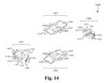
- the distraction instrumentcomprises a tubular body, a control rod positioned at least partially within the tubular body, wherein the control rod comprises a first end coupled with a handle and extending out a first side of the tubular body and a second end including an engaging element and extending out a second side of the tubular body and a head assembly comprising a plurality of plates and operably coupled with engaging element of the control rod such that manipulating the control rod with respect to the head assembly causes the plates to separate.
- the head assemblyis operably coupled with the engaging element such that rotation of the control rod with respect to the head assembly causes the plates to separate and rotation in the opposite direction causes the plates to contract.
- the head assemblyfurther comprises a jack mechanism coupled between the plates that effectuates the separating and the contracting of the plates and is configured to fit within one or more recesses within the plates when the plates are fully contracted.
- the instrumentfurther comprises an indicator positioned on the surface of the instrument, wherein the indicator dynamically indicates the distance between the plates.
- the indicatorindicates one or more values corresponding to how much one or more controls of one or more bone fusion implant devices must be rotated to extend one or more tabs of the devices such that the devices have height equal to the distance between the plates.
- the instrumentfurther comprises a force sensor coupled to the head assembly, wherein the force sensor measures a level of force resisting the separation of the plates.
- the indicatorindicates the level of force measured by the force sensor.
- the head assemblyis configured to stop the plates from further separating once the level of force measured by the force sensor equals a threshold level.
- the instrumentfurther comprises a motor and a motor control coupled with the control rod, wherein the motor control controls the operation of the motor and the motor enables motorized manipulation of the control rod to separate the plates.
- a fourth aspect of the present applicationis directed to a method of using a distraction instrument to measure the amount of space in a desired location.
- the methodcomprises inserting the distraction instrument in the desired location, wherein the distraction instrument comprises a tubular body, a control rod positioned at least partially within the tubular body, wherein the control rod comprises a first end coupled with a handle and extending out a first side of the tubular body and a second end including an engaging element and extending out a second side of the tubular body and a head assembly comprising a plurality of plates and operably coupled with engaging element of the control rod such that moving the control rod with respect to the head assembly causes the plates to separate and separating the plates until the plates reach bounds of the desired location by manipulating the control rod with respect to the head assembly.
- the manipulating the control rodcomprises rotating the control rod with respect to the head assembly wherein rotation in a first direction causes the plates to separate and rotation in a second direction causes the plates to contract.
- the head assemblyfurther comprises a jack mechanism coupled between the plates that effectuates the separating and the contracting of the plates and is configured to fit within one or more recesses within the plates when the plates are fully contracted.
- the instrumentfurther comprises an indicator positioned on the surface of the instrument, wherein the indicator dynamically indicates the distance between the plates.
- the indicatorindicates one or more values corresponding to how much one or more controls of one or more bone fusion implant devices must be rotated to extend one or more tabs of the devices such that the devices have height equal to the distance between the plates.
- the instrumentfurther comprises a force sensor coupled to the head assembly, wherein the force sensor measures a level of force resisting the separation of the plates.
- the indicatorindicates the level of force measured by the force sensor.
- the head assemblyis configured to stop the plates from further separating once the level of force measured by the force sensor equals a threshold level.
- the instrumentfurther comprises a motor and a motor control coupled with the control rod, wherein the motor control controls the operation of the motor and the motor enables motorized manipulation of the control rod to separate the plates.
- a fifth aspect of the present applicationis directed to a bone fusion device for insertion into a desired location.
- the devicecomprises a body having an interior cavity, a tab configured to fit within the interior cavity and selectively move from a retracted position within interior cavity of the body to an extended position extending out of the body, a plurality of extension assemblies coupled to a different portion of the tab and configured to move the tab between the retracted position and the extended position and a position locking mechanism operably coupled with each of the plurality of extension assemblies and configured to provide a plurality of locking positions that the plurality of extension assemblies are biased to stay in by the position locking mechanism.
- the plurality of extension assembliesare configured to move the different portions of the tab between the retracted position and the extended position independent of the remainder of the extension assemblies.
- the position locking mechanismcomprises a dial operably coupled with one of the plurality of extension assemblies such that when the one of the plurality of extension assemblies is rotated the dial is also rotated.
- the position locking mechanismcomprises one or more stops operably coupled with the dial such that when the one of the plurality of extension assemblies is in one of the locking positions the interface between the dial and the stops provides a biasing force that resists the movement of the one of the plurality of extension assemblies out of the one of the locking positions.
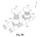
- FIG. 1Aillustrates an external perspective view of a bone fusion device according to some embodiments.
- FIG. 1Billustrates an internal perspective view of a bone fusion device according to some embodiments.
- FIG. 2illustrates a perspective view of the components of the bone fusion device according to some embodiments.
- FIG. 3Aillustrates a cross sectional view of the bone fusion device with the tab retracted according to some embodiments.
- FIG. 3Billustrates a cross sectional view of the bone fusion device with the tab extended according to some embodiments.
- FIG. 4illustrates a flow chart of a method of operating the bone fusion device according to some embodiments.
- FIG. 5illustrates the bone fusion device comprising one or more bone plugs according to some embodiments.
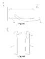
- FIG. 6Aillustrates a frontal view of a bone fusion device according to some embodiments.
- FIG. 6Billustrates a side view of a bone fusion device according to some embodiments.
- FIG. 6Cillustrates a top view of an elongated member inserted within a canal of a bone fusion device according to some embodiments.
- FIG. 6Dillustrates a frontal and profile view of an elongated member according to some embodiments.
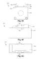
- FIG. 6Eillustrates a front view of the bone fusion device having one or more tangs according to some embodiments.
- FIG. 6Fillustrates a profile view of the bone fusion device having one or more tangs according to some embodiments.
- FIG. 6Gillustrates a top view of the bone fusion device having one or more tangs according to some embodiments.
- FIG. 7illustrates a flowchart directed to a method of using the bone fusion system according to some embodiments.
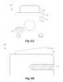
- FIG. 8Aillustrates a top view of a bone fusion device according to some embodiments.
- FIG. 8Billustrates a top view of a bone fusion device according to some embodiments.
- FIG. 8Cillustrates a top view of a bone fusion device according to some embodiments.
- FIG. 8Dillustrates a top and perspective view of a bone fusion device according to some embodiments.
- FIG. 8Eillustrates a top and perspective view of a bone fusion device according to some embodiments.
- FIG. 8Fillustrates a top and perspective view of a bone fusion device according to some embodiments.
- FIG. 8Gillustrates a perspective view of a bone fusion device according to some embodiments.
- FIG. 9illustrates a cross sectional perspective view of a bone fusion device having one or more angled drive screws according to some embodiments.
- FIG. 10illustrates a flowchart directed to a method of using a bone fusion device according to some embodiments.
- FIG. 11illustrates a flowchart directed to a method of using a bone fusion device according to some embodiments.
- FIG. 12illustrates a perspective view of a distraction instrument for measuring the space to be filled by a bone fusion device according to some embodiments.
- FIG. 13illustrates a top cross sectional view of the distraction body according to some embodiments.
- FIG. 14illustrates a perspective view of the components of the retraction head of the retraction instrument according to some embodiments.
- FIG. 15Aillustrates cross sectional view of the head of the retraction instrument with the plates fully retracted according to some embodiments.
- FIG. 15Billustrates cross sectional view of the head of the retraction instrument with the plates fully extended according to some embodiments.
- FIG. 16illustrates a flow chart of a method of operating the retraction instrument according to some embodiments.
- FIG. 17Aillustrates a top view of the bone fusion device comprising a webbing according to some embodiments.
- FIG. 17Billustrates a cross-sectional side view of the bone fusion device comprising a webbing according to some embodiments.
- FIG. 18Aillustrates a perspective view of a bone fusion system according to some embodiments.
- FIG. 18Billustrates a perspective view of a bone fusion system according to some embodiments.
- FIG. 19illustrates a perspective view of a bone grafting material bag according to some embodiments.
- FIG. 20illustrates a flowchart directed to a method of using the bone fusion system according to some embodiments.
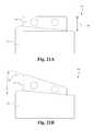
- FIG. 21Aillustrates a bone fusion device with a tab configured to have the maximum parallel distraction according to some embodiments.
- FIG. 21Billustrates a bone fusion device with a tab configured to have the maximum angle according to some embodiments.
- FIG. 22illustrates a bone fusion device having a position locking mechanism according to some embodiments.
- FIGS. 1A and 1Billustrate an external and internal perspective view of a bone fusion device 100 according to some embodiments.
- the bone fusion device 100comprises a body 102 , at least one tab 104 and a plurality of tab extension assemblies each comprising a drive screw 106 A, 106 B, a gear 108 A, 108 B and a supporting jack 110 A, 110 B.
- the device 100is able to comprise a single tab extension assembly.
- the front tab extension assemblycomprises a front drive screw 106 A which is mechanically coupled to a front supporting jack 110 A via a front gear 108 A
- the back tab extension assemblycomprises a rear drive screw 106 B which is mechanically coupled to a rear supporting jack 110 B via a rear gear 108 B.
- the supporting jacks 110 A, 110 Bare able to be individually and selectively raised or lowered with respect to the gears 108 A, 108 B by rotating or otherwise manipulating the corresponding drive screws 106 A, 106 B of the extension assemblies. As shown in FIG.
- the drive screws 106 A, 106 Bwhen combined with the body 102 and tab 104 , the drive screws 106 A, 106 B are able to be positioned within a pair of screw channels 204 of the body 102 (see FIG. 2 ) and the supporting jacks 110 A, 110 B are able to couple with the jack holes 208 at the front and rear of the tab 104 . Accordingly, by accessing and adjusting the drive screws 106 A, 106 B of the tab extension assemblies through the screw channels 204 of the body 102 , a user is able to not only selectively extend and retract the tab 104 a desired distance from the body 102 , but also is able to adjust the angle of the tab 104 by lowering or raising the sides of the tab 104 with respect to each other.
- the tab extension assembliesare able to comprise other components for selectively raising or lowering the tab 104 such as a plurality of angled extending blocks that are able to be individually controlled by drive screws such that they press against the tab 104 to selectively extend/retract and adjust the angle of the tab 104 .
- the bone fusion device 100is able to be constructed from a high strength biocompatible material, such as titanium, which has the strength to withstand forces in the spine that are generated by a patient's body weight and daily movements.
- a high strength biocompatible materialsuch as titanium
- part or all of the bone fusion device 100is able to be constructed from one or more of the group consisting of ceramics, high strength biocompatible material, a polymer such as PEEK, PEKK and other polymeric materials, stainless steel, titanium, titanium alloys such as nitinol and other biocompatible metals.
- the materials used to construct the bone fusion deviceinclude using additives, such as carbon fibers for better performance of the materials under various circumstances.
- the base biocompatible materialis often textured or coated with a porous material conducive to the growth of new bone cells on the bone fusion device 100 .
- FIGS. 1A and 1Billustrate a single tab 104 having a pair of extension assemblies
- the bone fusion device 100is able to comprise any number of tabs 104 each having any number of extension assemblies.
- the extension assembliesare shown as coupling to a front end and a back end of the tab 104 , the assemblies are able to be coupled to any portion of the tab 104 such that the angle of the tab 104 in any plane is able to be adjusted using the extension assemblies.
- another side or portion of the tab 104is able to be selectively raised or lowered with respect to the body 102 and/or other portions of the tab 104 .
- FIG. 2illustrates a perspective view of the components of the bone fusion device 100 according to some embodiments.
- the body 102comprises a body cavity 202 for housing the other components in a retracted state, one or more screw channels 204 for receiving the drive screws 106 A, 106 B, and one or more body apertures 206 for providing access to the cavity 202 .
- the body 102houses the tab 104 and tab extension assemblies within the body cavity 202 such that when the device 100 is in a retracted state the tab 104 and tab extension assemblies are all positioned within the outer dimensions of the body 102 . This enables the bone fusion device 100 to have the smallest profile possible when in the tab 104 is retracted thereby minimizing the size of the required surgical incision for the bone fusion surgery.
- the body 102has a substantially rectangular structure with an angled upper surface that aligns with the upper surface of the tab 104 when the tab 104 is retracted.
- the upper surface of the body 102is angled downward from front to back such that the front wall is higher than the back wall.
- the upper surface of the body 102is able to be angled upward from front to back and/or otherwise angled.
- the body 102is able to comprise other shapes such as shapes that substantially conform to the shape of vertebrae.
- the screw channels 204positioned such that the screws 106 A, 106 B are accessible from the same side of the body 102 .
- the channels 204are able to be positioned such that the screws 106 A, 106 B are accessible from one or more different sides of the body 102 .
- the apertures 206 of the body 102extend from the cavity 202 to the exterior of the body 102 .
- the apertures 206permit bone graft material to be inserted into the device 100 and to contact the vertebral bone before or after the device 100 has been inserted between the vertebrae of the patient.
- bone graft materialis able to refer to materials, biologics or other structures that promote osteoinduction and/or osteoconduction as are well known in the art.
- the bone graft materialis able to comprise, in combination or separately, one or more of autologous bone, allograft bone, artificial bone paste, artificial bone putty, osteoinduction material, osteoconduction material or other “scaffolding” for bone to grow upon and to induce bone growth as are well known in the art.
- the bone graft material and the surface texturing of the device 100encourage the growth and fusion of bone from the neighboring vertebrae. The fusion and healing process will result in the bone fusion device 100 aiding in the bridging of the bone between the two adjacent vertebral bodies of the spine which eventually fuse together during the healing period.
- the body 102comprises a single aperture 206 positioned on a rear surface, the body 102 is able to comprise any number of apertures 206 positioned on any of the surfaces of the body 102 .
- the body 102 of the bone fusion device 100comprises one or more gripping channels (not shown) each having at least one gripping aperture.
- the gripping aperturesare able to receive the gripping fingers of a bone fusion device insertion instrument such that the instrument cannot slip out of place during operation.
- the gripping channels and insertion instrumentare able to be substantially similar in operation and structure to the bone fusion device channels and bone fusion device insertion instrument described in U.S. Provisional Application No. 61/521,681, filed Aug. 9, 2011 and entitled “BONE FUSION DEVICE, APPARATUS AND METHOD,” which is hereby incorporated by reference.
- an insertion instrumentis able to grip and insert the bone fusion device 100 while preventing or at least minimizing the risk of the insertion instrument and/or bond fusion device 100 slipping out of place. Indeed, this security is necessary to ensure that the surgeon is able to precisely place and control the device 100 within a patient during surgery.
- the tab 104comprises one or more tab apertures 210 and one or more jack holes 208 such that there is at least one jack hole 208 for each jack 110 A, 110 B.
- the jack holes 208are positioned and sized such that the ends of the jack heads 224 of the jacks 110 A, 110 B are able to couple to the tab 104 by being positioned within the jack holes 208 .
- a pair of jack holes 208are able to be positioned across from each other on the tab 104 such that the holes 208 straddle each jack head 224 preventing the jack 110 A, 110 B from separating from the tab 104 .
- the jack holes 208(and at least a portion of the profile of the jack heads 224 ) are substantially circular such that when coupled to the jacks 110 A, 110 B, the jacks 110 A, 110 B are able to rotate within the jack holes 208 with respect to the tab 104 .
- this rotational couplingprovides the advantage of enabling the angle of tab 104 with respect to the body 102 and/or extension assemblies to be adjusted because the rotation of the jacks 110 A, 110 B within the holes 208 corresponds to the angle change of the tab 104 with respect to the body 102 and/or assemblies.
- the jack holes 208 and jack heads 224are able to comprise ball joints or other shapes and/or profiles that enable both coupling and rotation as are well known in the art.
- the tab 104is shaped such that the tab 104 is able to fit within the cavity 202 of the body 102 .
- the tab 104is shaped such that its perimeter profile matches the perimeter of the cavity 202 and/or such that the outwardly facing surface of the tab 104 is substantially flush with the frame 114 of the bone fusion device 100 when the tab 104 is in the retracted position.
- the upper surface of the tab 104is angled downward from front to back such that the front wall is higher than the back wall.
- the upper surface of the tab 104is able to be angled upward from front to back and/or otherwise angled.
- the tab 104is able to comprise other shapes as are well known in the art.
- tabs 104 having upper surfaces of varying anglesare able to be interchanged within the bone fusion device 100 .
- a useris able to exchange the current tab 104 of a device 100 with a different tab 104 having a differently angled upper surface.
- Thisallows the same bone fusion device 100 to be switched from having the maximum parallel distraction 120 with a tab 104 with a parallel upper surface as shown in FIG. 21A to the maximum angle 122 with a tab 104 having the maximum angled upper surface as shown in FIG. 21B or angles in between.
- the outwardly facing surface of the tab 104has sharp serrated edges, protrusions, ridges or threads along the length of the tab 104 for engaging the adjacent vertebrae.
- the tab 104comprises a single tab aperture 210 positioned on an upper surface
- the tab 104is able to comprise any number of tab apertures 210 positioned on any of the surfaces of the tab 104 .
- the drive screws 106 A, 106 Beach comprise a positioning aperture 214 , a threaded portion 212 and a recessed portion 216
- the gears 108 A, 108 Beach comprise gear teeth 218 and interior threading 220
- the jacks 110 A, 110 Beach comprise a jack head 224 , exterior threading 222 and a bottom protrusion 226 .
- the threaded portion 212 of the drive screws 106 A, 106 Bis positioned such that the threads align with the gear teeth 218 of one of the gears 108 A, 108 B and the interior threading 220 of the gears 108 A, 108 B matches the exterior threading 222 of the jack heads 224 when the jack heads 224 are positioned within the gears 108 A, 108 B.
- the threaded portion 212applies force to the gear teeth 218 rotating the interior threading 220 of the gears 108 A, 108 B.
- This rotationcauses the interior threading to apply force to the exterior threading 222 of the jacks 110 A, 110 B causing the jacks 110 A, 110 B to extend out of or retract further within the gears 108 A, 108 B.
- the screws 106 A, 106 Bare rotated in a first direction, the jacks 110 A, 110 B are extended out of the gears 108 A, 108 B until the bottom protrusion 226 reaches the interior threading 220 (see FIG. 3B ).
- the jacks 110 A, 110 Bare retracted further within the gears 108 A, 108 B until the bottom of the jack heads 224 abut the upper surface of the gears 108 A, 108 B (see FIG. 3A ).
- the tab extension assembliesare able to selectively retract/extend and adjust the angle of the tab 104 with respect to the body 102 .
- one or more of the drive screws 106 A, 106 B, gears 108 A, 108 B and/or jacks 110 A, 110 Bare able to be mechanically coupled using other mechanically coupling components as are well known in the art.
- a universal jointis able to be used instead of the threaded portion 212 and gear teeth 218 in order to translate the rotation of the drive screws 106 A, 106 B to the gears 108 A 108 B.
- the positioning apertures 214 of the drive screws 106 A, 106 Bare positioned on the end of the screws 106 A, 106 B such that they are accessible when the drive screws 106 A, 106 B are within the screw channels 204 of the body 102 . As a result, a user is able to insert one or more tool engaging members (not shown) into the positioning apertures 214 in order to rotate the drive screws 106 A, 106 B.
- the structure of the positioning apertures 214is configured such that the structure enables one or more engaging members of tools to rotate the drive screws 106 A, 106 B.
- the positioning apertures 214are able to match the engaging members of allen wrenches, flat-head screw drivers, phillips screw drivers and/or the engaging members of other types of tools as are well known in the art.
- the recessed portions 216 of the drive screws 106 A, 106 Bare positioned such that they are adjacent to and/or surround the gear 108 A, 108 B that is not mechanically coupled to the threaded portion 212 of that drive screw 106 A, 106 B.
- the recessed portions 216are able to help hold the gears 108 A, 108 B and screws 106 A, 106 B in place with respect to each other while not translating the rotation of the screws 106 A, 106 B to the gear 108 A, 108 B of the other tab extension assembly.
- the recessed portions 216are able to be omitted.
- the recessed portions 216are able to be omitted and the threaded portion 212 is able to protrude out from the cylindrical body of the screws 106 A, 106 B in order to maintain mechanical coupling with the gear teeth 218 .
- the body 102further comprises one or more tool channels (not shown) that selectively couple with a tool when the engaging member of the tool is coupled with one or more of the positioning apertures 214 .
- the tool and its engaging memberis able to be prevented from slipping out of the positioning apertures 214 which is able to cause harm to a patient during an insertion procedure.
- FIGS. 3A and 3Billustrate cross sectional view of the bone fusion device 100 with the tab 104 fully retracted and fully extended, respectively, according to some embodiments.
- the jacks 110 A, 110 Bare fully retracted within the gears 108 A, 108 B and the outward facing surface of the tab 106 is substantially flush with the upper surface of the body 102 .
- the bone fusion device 100creates the smallest profile possible and thus is able to be surgically inserted between two vertebrae of a patient with a minimally invasive procedure.
- FIG. 3Aillustrate cross sectional view of the bone fusion device 100 with the tab 104 fully retracted and fully extended, respectively, according to some embodiments.
- FIG. 3Awhen the device is in the retracted position, the jacks 110 A, 110 B are fully retracted within the gears 108 A, 108 B and the outward facing surface of the tab 106 is substantially flush with the upper surface of the body 102 .
- the bone fusion device 100creates the
- the bone fusion device 100provides the advantage of enabling not only the tab height to be adjusted to a desired level, but also that the tab angle to be adjusted to a desired degree in order to best correspond to the vertebrae thereby increasing the stability of the bone fusion and the success of the surgery.
- FIG. 5illustrates the bone fusion device 100 comprising one or more bone plugs 500 according to some embodiments.
- the bone plugs 500comprise a plug body 502 having at least one desired profile or perimeter 504 .
- the perimeter 504 of the plug body 502is sized such that the plug 500 fits within one or more of the tab 104 or body 102 apertures 210 , 206 .
- one or more bone plugs 500are able to be used to fill one or more of the apertures of the bone fusion device 100 . This creates the benefit of reducing the amount of bone graft material that needs to be inserted into the cavity 202 of the bone fusion device 100 .
- the bone fusion device 100comprises at least one bone plug 500 for each aperture within the body 102 and/or the tab 104 .
- at least one of the apertures within the body 102 and/or the tab 104are able to remain “unplugged” such that bone graft material is able to be injected into the device 100 through the unplugged apertures.
- the bone plugs 500are sized such that the perimeter 504 will contact the inner surface of the apertures 210 , 206 when the bone plug 500 is inserted into the aperture such that friction from the contact will hold the plug 500 in place.
- the perimeter 504is able to be sized slightly larger than the inner surface of the apertures 210 , 206 such that upon insertion into an aperture either the aperture or the plug 500 flexes, wherein the resistance to the flexing provides a force holding the plug or plugs 500 in place within the aperture.
- the plugs 500are able to have differently shaped perimeters 504 as are well known in the art.
- the body 502 of one or more of the plugs 500has a thickness greater than the thickness of the apertures 206 , 210 such that the plugs 500 are able to protrude into and/or out of the bone fusion device 100 when positioned within one of the apertures 206 , 210 .
- the body 502is able to be less thick and/or be positioned such that body 502 aligns with the surface of the bone fusion device 100 when inserted in an aperture 206 , 210 .
- the body 502 of the plugs 500comprises bone.
- the body 502is able to comprise one or more materials selected from the group consisting of bone, bone graft material capable of retaining a desired shape, bone-like substances known to aid in the fusion process and other biocompatible materials as are well known in the art.
- the one or more of the plugs 500are flexible.
- the plugs 500are able to be inflexible or rigid.
- the bone plugs 500are described in reference to the bone fusion device 100 , it is understood that they are able to be sized in order to fill the apertures of other types of bone fusion devices.
- FIG. 4illustrates a flow chart of a method of operating the bone fusion device 100 according to some embodiments.
- a userrotates one or more of the drive screws 106 A, 106 B of the tab extension assemblies until the tab 104 is in a fully retracted position at the step 402 .
- the userinserts the bone fusion device 100 into the desired position within the patient at the step 404 .
- the desired positioncomprises between or adjacent to one or more vertebrae.
- the bone fusion device 100is inserted anteriorly.
- the bone fusion device 100is able to be inserted posteriorly, laterally, far lateral, extra lateral, extreme lateral, transforaminaly, or other directions as are well known in the art.
- the device 100comprises a single tab extension assembly such that only the drive screw or screws associated with the single tab extension assembly need to be rotated.
- the desired anglecomprises the angle required to cause the outward facing surface of the tab 104 to substantially match the angle of the surface of the adjacent vertebrae.
- the angle of the surface of the tab 104is able to be adjusted before and/or during the extension of the tab 104 to the desired height.
- the tab 104 and the remainder of the bone fusion device 100is able to exert a satisfactory force between the bone fusion device and the bones to be fused.
- the bone fusion device 100is able to remain in place.
- materialsuch as autograft material, for fusing the bones together is able to be inserted through the apertures 206 , 210 of the bone fusion device 100 to promote healing.
- the insertion of the materialis able to be omitted or occur before insertion of the bone fusion device 100 .
- the methodis able to comprise a plurality of bone fusion devices 100 that are each able to be used as described herein.
- the plurality of bone fusion devices 100are able to be inserted and/or adjusted together or separately.
- a single bone fusion device 100is able to be used.
- a single bone fusion device 100is able to be used for a cervical surgery operation. Therefore, the bone fusion device 100 provides the advantage of a small incision and minimally invasive (arthroscopic) surgical procedure which advantageously promotes health and rapid recovery by the patient.
- bone growthoccurs around the bone fusion device and particularly at the location of the extended tab, such that the bone fusion device is further secured by the bone growth, which further promotes a superior, robust bone fusion result.
- FIGS. 6A-Cillustrate a front, side and top view of a bone fusion device 600 having one or more canals 621 according to some embodiments.
- the bone fusion device 600 shown in FIGS. 6A-Cis substantially similar to the bone fusion device 100 except for the differences described herein.
- the bone fusion device 600comprises a body 614 having one or more canals 621 and one or more tabs 630 .
- the canals 621are positioned along the sides of the body 614 and a sized such that the canals 621 are able to receive or house a portion or all of one or more elongated members 623 (see FIG. 6D ).
- one or more of the canals 621are able to be positioned within other portions of the body 614 including different angles and orientations in one or all axises of the bone fusion device 600 .
- one or more of the canals 621are able to be positioned within one or more of the tabs 630 .
- the canals 621extend from a central area of the body 614 to the front or back side of the body 614 such that an elongated member 623 is able to enter the canals 621 from the front or back side of the body 614 (and/or the side of the body 614 ).
- one or more of the canals 621extend along the entire bone fusion device 600 from the front side to the back side of the body 614 (or vice versa), such that an elongated member 623 is able to enter the canals 621 from both or either the front or back side of the body 614 .
- one or more of the canals 621are able to be housed entirely within an inner portion of the body 614 such that the canals 621 breach neither the front nor the back side of the body 614 and the elongated members 623 are only able to enter the canals 621 from the side of the body 614 .
- FIG. 6Cillustrates a top view of an elongated member 623 inserted within a canal 621 of the bone fusion device 600 according to some embodiments.
- the elongated member 623is curved and extends from the front of the body 614 and canal 621 to a central portion of the body 614 .
- the elongated members 623are able to be configured such that the members 623 extend to the front, back, or other portions of the body 614 .
- one or more of the elongated member 621are able to extend out of the canals 621 into the central cavity of the body 614 and/or outside of the body 614 .
- the members 623are able to be curved or otherwise shaped such that the members 623 enter a desired portion of the body 614 while not extending out of the side of the body 614 more than a desired distance (e.g. 1 mm).
- the desired portion of the body 614 in which the members 623 are positionedcomprise between the front or back side of the body 614 .
- the members 623are able to be configured such that the members 623 are able to remain entirely within the canals 621 and/or cavity of the body 614 .
- one or more of the components of the bone fusion device 600is able to be incorporated into the other bone fusion devices described herein.
- FIG. 6Dillustrates a frontal and profile view of an elongated member 623 according to some embodiments.
- the elongated member 623comprises a body 625 and one or more apertures 627 .
- the body 625is sized such that the member 623 is able to partially or wholly fit within the canals 621 .
- the body 625is able to be tubular such that material, such as autograft material, is able to be inserted into the body 625 via the apertures 627 .
- the body 625is able to be partially or wholly solid, wherein if the body 625 is wholly solid the apertures 627 are able to be omitted.
- the body 625is able to comprise other solid or hollow shapes as are well known in the art.
- the body 625 of the elongated member 623is substantially straight.
- the body 625is able to comprise one or more curves and/or corners as are well known in the art.
- the body 625is able to be curved such that the member 623 is able to curve from the canal 621 into the cavity of the body 614 of the bone fusion device 600 .
- the elongated member 623is able to be bendable such that body 625 is able to be bended to a desired shape by a user and the body 625 will retain the desired shape.
- the body 625is filled with one or more of calcium triphosphate, hydroxyapatite or other materials that are constituents of bone or promote bone growth as are well known in the art.
- the body 625is able to comprise materials that are constituents of bone or promote bone growth as are well known in the art.
- the body 625is able to comprise the same or similar materials to that of the bone fusion device 600 .
- the bone fusion device 600 and the elongated members 623are able to be used to position bone grafting promotive material along the device 600 after the bone fusion device 600 has been positioned into place within a patient. This enables the bone fusion device 600 to ensure that the bone fusion material is not pushed out of place during the extension of the tabs 630 or other portions of the procedure.
- FIGS. 6E-Gillustrate a front, profile and top view of the bone fusion device 2400 having one or more tangs 2406 according to some embodiments.
- the bone fusion device 2400 shown in FIGS. 6E-Gis substantially similar to the bone fusion device 100 except for the differences described herein.
- the bone fusion device 2400comprises a body 2402 having one or more tang recesses 2408 and one or more tabs 2404 having one or more tangs 2406 .
- the tangs 2406extend from one or more of the tabs 2404 and increase the surface area of the tabs 2404 thereby promoting bone growth and aiding the fusion process.
- the tang recesses 2408are sized and positioned to receive or house each of the tangs 2406 when the tabs 2404 are retracted into the body 2402 in order to maintain the minimal size of the device 2400 when in the retracted position.
- each tang 2406has a separate corresponding tang recess 2408 .
- one or more of the tang recesses 2408are able to house a plurality of tangs 2406 .
- the tangs 2406are positioned around the top perimeter of one or more of the tabs 2404 .
- the tangs 2406are able to be positioned elsewhere on one or more of the tabs 2404 such that the tangs 2406 are able to increase the surface area of the tabs 2404 .
- one or more of the tangs 2406are able to extend beyond the perimeter of the body 2402 .
- a portion of the extended tangs 2406would be housed within the tang recesses 2408 and a portion of the tangs 2406 would protrude out of the tang recesses 2408 beyond the perimeter of the body 2402 .
- the tangs 2406 and tang recesses 2408are described in reference to the bone fusion device 2400 , it is understood that they are able to be incorporated into the other bone fusion devices described herein.
- a method of using the bone fusion device 600is illustrated by the flow chart in FIG. 7 .
- a userselects one or more elongated members 623 based on the shape and size of the elongated members 623 at the step 702 .
- the userselects one or more elongated members 623 and bends them into a desired shape and size.
- the userfills one or more of the selected elongated members 623 with bone grafting material at the step 704 .
- the userpositions the bone fusion device 600 within the patient at the step 706 .
- the userinserts the one or more elongated members 623 within and/or outside the canals 621 and/or body 614 of the bone fusion device 600 at the step 708 .
- one or more of the elongated members 623are able to be positioned within and/or outside of the canals 621 before or during the positioning of the bone fusion device 600 within the patient.
- the method of using the bone fusion systemprovides the advantage of allowing the bone grafting material to be packed into the elongated members 623 and positioned after the positioning of the bone fusion device 600 within the patient.
- the bone fusion device 600is able to prevent the elongated members 623 from being moved during the positioning of the bone fusion device within the patient thereby keeping the bone grafting material in the desired position and/or shape with respect to the adjacent bones and bone fusion device 600 such that quicker and stronger bone fusion is promoted speeding up the healing process.
- one or more of the steps of the above methodare able to be omitted or combined with the other methods described herein.
- FIGS. 8A-8Gillustrate top and perspective views of a bone fusion device 800 according to some embodiments.
- the bone fusion devices 800 shown in FIGS. 8A-8Gare substantially similar to the bone fusion device 100 except for the differences described herein.
- the bone fusion device 800comprises drive screws 808 one or more tabs 830 and a body/frame 814 .
- the body 814comprises an oval shaped ( FIG. 8A ), kidney shaped ( FIG. 8B ), round shaped ( FIG. 8C ), rectangular shaped ( FIG. 8D ), banana shaped ( FIG. 8E ) or otherwise shaped ( FIG.
- top/bottom profilesuch that the shape of the top/bottom profile of the body 814 is substantially similar to the shape of the horizontal profile of one or more vertebrae.
- the top/bottom profile of the body 814is able to comprise one or more other shapes that substantially match bones that are to be fused to the bone fusion device 800 .
- the top profile of the tabs 830are able to be shaped as described herein, wherein the body 814 remains the standard shape as described above.
- the top profile of the tabs 830are shaped substantially similar to the top/bottom profile of the body 814 .
- the tabs 830have rounded edges to match the perimeter of the frames 814 .
- the top profile of the tabs 830is able to comprise other shapes as are well known in the art.
- the top profile shapes of the body 814are between 15 and 25 mm along the anterior/posterior axis and between 20 and 45 mm along the lateral axis.
- other dimensionsare envisioned.
- the body 814is able to be less than 15 mm along the anterior/posterior axis and less then 20 mm along the lateral axis.
- the body 814is able to be 55 mm or longer along the lateral axis (typically for extreme lateral lumbar interbody fusion).
- the body 814 and/or tab 830have an angled upper surface such that the angle of the bone fusion device 800 matches the angle between the vertebrae. In some embodiments, the angle is equal to 15 degrees. Alternatively, other angles are able to be utilized. In some embodiments, as shown in FIG. 8G , the drive screws 808 are able to be non-parallel with the elongated top dimension/axis 815 of the body 814 .
- the bone fusion device 800provides the advantage of substantially matching the horizontal profiles of the bones to be fused, thereby increasing the strength and efficiency of the fusion process.
- the profile shapesprovide the advantage of enabling a user to select a bone fusion device 800 with a top profile shape whose orientation matches the insertion orientation of the operation.
- the angles at which the drive screws 808 are oriented with respect to the elongated axis 815 of the body 814is able to be selected to match the angle of access provided by a desired operation.
- the bone fusion device 800does not need to be turned to be in the proper orientation between the bones of the patient whether the procedure is anterior, posterior, lateral, far-lateral or transforaminal lumbar interbody fusion.
- the upper surface anglesprovide the advantage of enabling a user to select a bone fusion device 800 with a body 814 and/or tab 830 angle that matches the angle between the target vertebrae.
- FIG. 9illustrates a cross sectional perspective view of a bone fusion device 900 having one or more angled drive screws according to some embodiments.
- the bone fusion device 900 shown in FIG. 9is substantially similar to the bone fusion device 100 except for the differences described herein.
- the bone fusion device 900comprises a body 902 housing one or more drive screws 904 , 904 ′ and one or more gears 906 .
- At least one of the drive screws 904 ′is able to be angled with respect to the elongated dimension of the body 902 while still operable coupled with one of the gears 906 .
- a plurality or all of the drive screws 904 , 904 ′are able to be angled or non-parallel with respect to the elongated dimension of the body 902 .
- a useris able to control the extension, retraction and angle adjustment of the tab (not shown) by rotating the gears 906 using the drive screws 904 , 904 ′.
- the angled drive screws 904 ′are positioned such that the drive screw 904 is substantially perpendicular to the elongated dimension of the body 902 .
- the angled drive screws 904 ′are able to be positioned such that they each form any angle with the elongated dimension of the body 902 while still operably coupled to one of the gears 906 .
- the bone fusion device 900provides the advantage of allowing the tab to be extended/retracted and/or the angle of the tab adjusted from angles other than parallel to the elongated dimension of the body, which is critical in procedures where the device 900 is to be inserted from varying angles such as, for example, anterior lumbar interbody fusion, lateral lumbar interbody fusion or transforaminal lumbar interbody fusion.
- the differences to the bone fusion device 900 described in FIG. 9are able to be incorporated with and/or replace components of each of the other bone fusion devices described herein.
- a method of using the bone fusion device 800is illustrated by the flow chart in FIG. 10 .
- a userselects the body angle and/or top profile shape of a bone fusion device 800 based on a type of lumbar interbody fusion to be performed at the step 1002 .
- the userselects an elongated oval shape body 814 based on the type being extreme lateral lumbar interbody fusion.
- the userselects a kidney or rounded shape body 814 based on the type being anterior lumber interbody fusion.
- the userselects the shape of the top profile of the body 814 of a bone fusion device 800 based on a horizontal profile of the bone or bones to be fused to the device.
- a bone fusion deviceis able to be selected because the device 800 has a top profile shape that substantially matches the shape of the horizontal profile of a cervical spinal bone or bones to be fused with.
- the userinserts the selected bone fusion device 800 in between the desired bones according to the type of lumbar interbody fusion to be performed at the step 1004 .
- the bone fusion device 600is able to be positioned offset from the center of the adjacent bones and/or discs.
- the method of using the bone fusion device 600provides the advantage of enabling a user to select a device 800 with desired dimensions of angle and/or top profile based on the type of procedure thereby increasing the effectiveness of the procedure.
- one or more of the steps of the above methodare able to be omitted or combined with the other methods described herein.
- a method of using the bone fusion device 900is illustrated by the flow chart in FIG. 11 .
- a userselects a bone fusion device 900 having one or more drive screws 904 , 904 ′ at a desired angle relative to the elongated dimension of the body 902 of the device 900 based on a type of lumbar interbody fusion to be performed at the step 1102 .
- the userselects angled drive screws 904 ′ that are substantially parallel to the elongated dimension of the body 902 based on the type being anterior lumbar interbody fusion.
- the userselects a bone fusion device 900 having angled drive screws 904 ′ at a desired angle relative to the elongated dimension of the body 902 based on the shape of the top profile of the body 902 of a bone fusion device 900 and the type of lumbar interbody fusion to be performed.
- the userinserts the selected bone fusion device 900 in between the desired bones according to the type of lumbar interbody fusion to be performed at the step 1104 .
- the method of using the bone fusion device 900provides the advantage of enabling a user to select a bone fusion device 900 having angled drive screws 904 ′ that form a desired angle with the elongated dimension of the body 902 of the bone fusion device 900 based on the type of procedure thereby increasing the effectiveness of the procedure.
- one or more of the steps of the above methodare able to be omitted or combined with the other methods described herein.
- FIG. 12illustrates a perspective view of a distraction instrument 1200 for measuring the space to be filled by a bone fusion device according to some embodiments.
- the distraction instrument 1200comprises a distraction body 1202 and a distraction head 1202 operably coupled together.
- FIG. 13illustrates a top cross sectional view of the distraction body 1202 according to some embodiments.
- the distraction body 1202comprises a handle 1302 , a engaging element 1304 and a guide element 1306 .
- the handle 1302is coupled with the engaging element 1304 which is positioned within the guide element 1306 such that a user is able to rotate, push and/or pull the handle 1302 in order to rotate, extend and/or retract the engaging element 1304 within or further out of the guide element 1306 .
- the handle 1302 and/or guide element 1306comprise one or more gripping ridges enabling a user to rotate or otherwise move the handle 1302 with respect to the guide element 1306 without slipping.
- the instrument 1200is able to comprise an electric motor and control interface (not shown) such that the movement of the handle 1302 is able to be effectuated by a user controlling the operation of the electric motor via the control interface.
- the guide element 1306comprises one or more a stop pins 1310 that couple to the stop apertures 1417 of the rear fitting 1414 of the rear jack assembly 1404 (see FIG. 14 ). When coupled within the stop apertures 1417 , the stop pins 1310 are able to prevent the distraction head 1202 from rotating with the engaging element 1304 as well as keeping the rear fitting 1414 of the rear jack assembly 1404 abut the end of the guide element 1306 .
- the engaging element 1304comprises a threaded portion 1312 positioned along the end of the engaging element 1304 such that the threaded portion 1312 is able to operably coupling with the threads 1418 of the front fitting 1415 of the front jack assembly 1406 (see FIG. 14 ).
- the threaded portion 1312is able to engage the threads 1418 of the front fitting 1415 causing the front fitting 1415 to slide toward or away from the rear fitting 1414 .
- the threaded portion 1312 and the threads 1418are able to be omitted and the end of the engaging element 1304 is able to be coupled to the front fitting 1415 such that when the engaging element 1304 is pulled into or pushed out of the guide element 1306 the coupling causes the front fitting 1415 to also slide toward or away from the rear fitting 1414 .
- the threaded portion 1312is a female thread such that when the engaging element 1304 is rotated, the threading 1312 causes the engaging element 1304 to retract into the guide element 1306 and the front fitting 1415 to slide toward the rear fitting 1414 . As a result, the engaging element 1304 does not protrude out of the front fitting 1415 during the expanding or contracting of the plates 1402 .
- the threading 1312male or female is able to be positioned in other places along the engaging element 1304 and complimenting threading is able to be positioned, for example, within the conduit 1416 of the rear fitting 1414 or within the end of the guide element 1306 .
- one or more of the handle 1302 , engaging element 1304 and/or the guide element 1306comprise one or more indicators 1308 that indicate values corresponding to the current separation between the plates 1402 of the head 1204 (see FIG. 14 ).
- the indicators 1308comprise first markings on the visually exposed surface of the engaging element 1304 and/or handle 1302 that move relative to corresponding second markings on the guide element 1302 when the engaging element 1304 is rotated or otherwise moved. As a result, based on the alignment of the first and second markings the current separation between the plates 1402 of the head 1204 is able to be determined.
- the indicators 1308are able to comprise a digital or analog readout/display that indicates the current level of distraction of the instrument 1200 .
- the motion of the handle 1302is effectuated by an electrical motor and the indicators 1308 are able to include the control interface for controlling the operation of the electrical motor.
- the indicators 1308are able to include the control interface for controlling the operation of the electrical motor.
- other types of indicating elements 1308 corresponding to the current separation of the plates 1402are able to be used as are well known in the art.
- the indicators 1308indicate a number of revolutions or rotations that the positioning element of a bone fusion device will require in order to extend the tabs to the height indicated by the separation of the plates 1402 .
- the a useris able to input or the instrument 1200 is able to be pre-programmed with the type of bone fusion device to be used and based on this data, the indicators 1308 are able to indicate the number of rotations/revolutions that the positioning element of a bone fusion device will require in order to extend the tabs to the height indicated by the separation of the plates 1402 .
- the indicators 1308are able to indicate a recommended size and/or type of bone fusion device to be used for filling the measured space.
- the distraction instrument 1200provides the advantage of indicating the best type/size of bone fusion device to use and/or the exact amount of rotation needed to a user of a bone fusion device such that the user does not overextend the tabs of the bone fusion device.
- the instrument 1200comprises a force measurement component (not shown) and/or the indicators 1308 indicate the amount of force on the plates 1402 that is resisting the expansion/distraction of the plates 1402 .
- the distraction instrument 1200is able to be configured to prevent the user from further extending/distracting the plates 1402 when a predefined and/or adjustable force threshold value is detected by the force measurement component. For example, if the distraction is effectuated by an electronically controlled motor the distraction system is able to be configured to automatically stop when the force threshold value is detected.
- the force measurement componentis able to be implemented mechanically such that the components of the instrument 1200 that effectuate the distraction of the plates 1402 prevent further distraction when a predetermined and/or adjustable amount of resistance is present.
- the distraction instrument 1200provides the benefit of enabling a user to manually stop, automatically stopping and/or preventing the user for continuing to distract the plates 1402 when the force measurement component and/or indicators 1308 indicate that a predetermined amount of expansion resistant force is detected on the plates 1402 .
- the distraction instrument 1200prevents over distraction that which results in inaccurate measurements and possible injury.
- FIG. 14illustrates a perspective view of the components of the retraction head 1204 of the retraction instrument 1200 according to some embodiments.
- the retraction head 1204comprises a pair of retraction plates 1402 coupled together by a rear jack assembly 1404 and a front jack assembly 1406 .
- the rear and front jack assemblies 1404 , 1405each comprise a rear/front fitting 1414 , 1415 having a fitting conduit 1416 and coupled to a plurality of legs 1422 via one or more fitting pins 1420 .
- the plurality of legs 1422each have a leg pin 1424 and a leg aperture 1419 , wherein the leg apertures 1419 are configured to slide onto a pair of fitting protrusions 1421 such that the legs 1422 are able to pivot/rotate about the fitting protrusions 1421 and are prevented from sliding off the protrusions 1421 by the fitting pins 1420 .
- two fitting protrusionsare each rotatably coupled to a pair of legs 1422 .
- more of less fitting protrusions 1421are able to be rotatably coupled to more or less legs 1422 .
- the protrusions 1421 and/or fitting pins 1420are able to be omitted and the legs 1422 are able to be rotatably coupled to the fittings 1414 , 1415 via other coupling mechanisms as are well known in the art.
- the conduit 1416 of the rear fitting 1414is bare whereas the conduit 1416 of the front fitting 1415 has an inner threading 1418 that is operably coupled to the threaded portion 1312 of the engaging element 1304 when the engaging element 1304 is positioned within the conduits 1416 of the retraction head 1204 .
- the engaging element 1304is able to freely move independent of the rear fitting 1414 , but causes the front fitting 1415 to move toward or away from the rear fitting 1414 along the engaging element 1304 when rotated.
- the threading 1418 of the conduit 1416 of the front fitting 1415is able to be omitted and the engaging element 1304 is able to be otherwise coupled to the front fitting 1415 such that when the engaging element 1304 is pulled into or pushed out of the guide element 1306 the coupling causes the front fitting 1415 to correspondingly slide toward or away from the rear fitting 1414 .
- the rear fitting 1414comprises one or more stop apertures 1417 that couple with the stop pins 1310 in order to prevent the distraction head 1202 from rotating with the engaging element 1304 and to keep the rear fitting 1414 of the rear jack assembly 1404 in contact with the end of the guide element 1306 .
- the stop pins 1310 and stop apertures 1417are able to be omitted and the rear fitting 1414 is able to be coupled to the guide element 1306 via other coupling mechanisms as are well known in the art.
- the retraction plates 1402each comprise one or more leg pin apertures 1408 , a pair of fitting cavities 1410 and a plate channel 1412 .
- the leg pin apertures 1408are configured to rotationally couple to the leg pins 1424 such that the plates 1402 are coupled together via the front and rear jack assemblies 1404 , 1406 .
- the legs 1422when the legs 1422 are caused to rotate about the protrusions 1421 (due to movement of the engaging element 1304 ), the legs 1422 also rotate within the leg pin apertures 1408 about the leg pins 1424 causing the plates 1402 to selectively move apart or come together.
- the fitting cavities 1410 and plate channels 1412 of the upper plate 1402align with the fitting cavities 1410 and plate channel 1412 of the lower plate 1402 .
- the height of the retraction head 1204 in the retracted positionis minimized because the rear and front fittings 1414 , 1415 are able to fit within the aligned fitting cavities 1410 and the engaging element 1412 is able to fit within the aligned plate channels 1412 .
- Thisprovides the advantage of minimizing the size of the required surgical incision for the bone fusion surgery measurement operation.
- FIGS. 15A and 15Billustrate cross sectional view of the head 1204 of the retraction instrument 1200 with the plates 1402 fully retracted and fully extended, respectively, according to some embodiments.
- FIG. 15Awhen the retraction instrument 1200 is in the retracted position, the plates 1402 are in contact such that the fittings 1414 , 1415 are all or partially housed within/between the plates 1402 . While in this position, the retraction instrument 1200 creates the smallest profile possible and thus is able to be surgically inserted between two vertebrae of a patient with a minimally invasive procedure. As shown in FIG.
- the retraction instrument 1200provides the advantage of a minimized retracted profile that enables a surgeon to measure the size of the space needed to be filled by a bone fusion device or other device while minimizing the surgical incision required to take the measurement.
- FIG. 16illustrates a flow chart of a method of operating the retraction instrument 1200 according to some embodiments.
- a userrotates or otherwise moves the engaging element 1304 until the head 1204 is in a fully retracted position at the step 1602 .
- the userinserts the retraction instrument 1200 into the desired position within the patient at the step 1604 .
- the desired positioncomprises between or adjacent to one or more vertebrae.
- the retraction instrument 1200is inserted anteriorly.
- the retraction instrument 1200is able to be inserted posteriorly, lateral, far-lateral or transforaminaly.
- the userrotates or otherwise moves the engaging element 1304 until the head 1204 is extended to a desired height at the step 1606 .
- the desired heightcomprises the height required such that the lower and upper plates 1402 abut the vertebrae.
- the indicators 1308indicate the amount of separation between the plates 1402 at the step 1608 .
- the indicators 1308indicate a type and/or size of bone fusion device to utilize to fill the measured space.
- the indicators 1308indicate a number of rotations/revolutions that the positioning element of a bone fusion device will require in order to extend the tabs to the height indicated by the amount of separation of the plates 1402 .
- the indicators 1308indicate the current amount of expansion resisting force on the plates 1402 .
- the desired heightcomprises the height or separation of the lower and upper plates 1402 when the indicators 1308 indicate the plates 1402 are experiencing a predetermined expansion resisting force threshold value.
- the userretracts and removes the retraction device 1200 from the patient at the step 1610 .
- the userthen inserts the a bone fusion device into the desired position and extends the tabs such that the bone fusion device fills the indicated height.
- the userextends the tabs such that the bone fusion device fills the indicated height by rotating the positioning element of the bone fusion device a number of times indicated by the indicators 1308 .
- the bone fusion device insertedwas selected based on size and/or type of bone fusion device indicated by the indicators 1308 .
- the retraction instrument 1200provides the advantage of determining the size of the space within the patient while only requiring a small incision and minimally invasive (arthroscopic) surgical procedure which advantageously promotes health and rapid recovery by the patient. Further, by determining the size of the space to be filled, the instrument 1200 provides the advantage of enabling the user to select a bone fusion device of the appropriate size to fit within the space and enables the user to pre-configure the tabs of the bone fusion device to near the height required to fill the space such that minimal extension of the tabs is required when the device is in place within the patient.
- FIGS. 17A and 17Billustrate a top and cross-sectional side view of the bone fusion device 100 comprising a webbing 1700 according to some embodiments.
- the webbing 1700comprises a webbing body 1702 having at least one webbing aperture 1704 for each jack 110 A, 110 B and one or more bracing members 1706 .
- the webbing apertures 1704are sized such that the jacks 110 A, 110 B fit snugly within the webbing apertures 1704 and the bracing members 1706 are sized such that they are able to brace the webbing 1700 against the inner walls of the body 102 when the jacks 110 A, 110 B are within the webbing apertures 1704 .
- the webbing 1700is able to support the jacks 110 A, 110 B such that the jacks 110 A, 110 B are restricted from moving along the plane of the webbing 1700 (e.g. laterally).
- the webbing 1700is able to be positioned substantially parallel or orthogonal to the bottom of the device body 102 .
- the webbing 1700is able to be positioned at an angle 1708 in any direction with respect to the plane formed by the bottom of the device body 102 .
- the webbing body 1702is substantially planar.
- the webbing body 1702is able to have bends and/or curves in order to better fit within the body 102 and/or support the jacks 110 A, 110 B.
- the webbing body 1702is able to extend to the bottom of the inner surface of the body 102 such that the webbing body 1702 is seated on the bottom of the inner surface of the body 102 .
- the upper surface of the webbing body 1702is able to be substantially planar or have bends and/or curves in order to better fit within the body 102 and/or support the jacks 110 A, 110 B.
- the bone fusion device 100is able to comprise a plurality of webbing bodies 1700 positioned at the same or different angles in order to provide increased support to the jacks 110 A, 110 B.
- the webbing body 1702comprises elastic materials such that as the jacks 110 A, 110 B move and apply force to the webbing body 1702 , the webbing body 1702 resists the movement along the plane of the webbing 1700 as the movement increases and springs the jacks 110 A, 110 B back in place as the force subsides.
- the webbing body 1702is able to comprise inelastic or rigid materials such that the jacks 110 A, 110 B are substantially prevented from moving along the plane of the webbing 1700 .
- the webbing body 1702is able to comprise both elastic and inelastic material such that the elastic portions allow some movement of the jacks 110 A, 110 B, but the inelastic portions limit the extent of this movement.
- the webbing 1700is shown in FIG. 17A as comprising six bracing members 1706 , it is understood that any number of bracing members 1706 are able to be used and each is able to be of varying sizes and positioned along any portion of the perimeter of the webbing 1700 .
- the webbing body 1702is able to comprise a single bracing member 1706 that forms the entire perimeter of the webbing 1700 and abuts the inner perimeter of the device body 102 .
- the webbing 1700is described in reference to the bone fusion device 100 , it is understood that the webbing 1700 is able to be used in conjunction with the other bone fusion devices described herein.
- FIGS. 18A and 18Billustrate perspective views of a bone fusion system 2100 according to some embodiments.
- the bone fusion devices 2102 shown in FIGS. 18A and 18Bare substantially similar to the bone fusion device 100 except for the differences described herein.
- the bone fusion system 2100comprises one or more bone fusion devices 2102 and one or more bone grafting material bags 2104 .
- the bone grafting material bags 2104are able to be positioned and/or coupled within the bone fusion device 2102 .
- the material bags 2104are also able to be positioned or coupled outside of the bone fusion device 2102 .
- FIG. 18Aillustrate perspective views of a bone fusion system 2100 according to some embodiments.
- the bone fusion devices 2102 shown in FIGS. 18A and 18Bare substantially similar to the bone fusion device 100 except for the differences described herein.
- the bone fusion system 2100comprises one or more bone fusion devices 2102 and one or more bone grafting material bags 2104 .
- the material bag 2104comprises a mesh frame 2202 , one or more support bars 2204 , at least one opening 2206 for filling the bag 2104 with bone graft material, one or more bag fasteners 2208 and one or more bag coupling elements 2210 .
- the support bars 2204 , bag fasteners 2208 and/or bag coupling elements 2210are able to be omitted.
- the support bars 2204couple to the mesh frame 2202 in order to help the mesh frame 2202 maintain its shape.
- the shape of the mesh frame 2202is a cylinder (as shown in FIGS. 18A and 19 ).
- the shape of the mesh frame 2202is able to be a “half-moon” prism (as shown in FIG. 18B ) or other shapes capable of holding a volume of bone grafting material as are well known in the art.
- the support bars 2204comprise polymeric materials such that the support bars 2204 are able to maintain the shape of the material bag 2104 .
- the support bars 2204are able to comprise other materials capable of supporting the shape of the bag 2104 as are well known in the art.
- the opening 2206enables bone grating material to be packed into the bone grafting material bag 2104 and is able to vary in size based on the size of the mesh frame 2202 .
- the bag fastener 2208is positioned on the mesh frame 2202 such that the bag fastener 2208 is able to releasably close or fasten the opening 2206 shut such that bone grafting material within the material bag 2104 is unable to escape through the opening 2206 .
- the bag fastener 2208comprises a hoop around the opening 2206 and a cinch cord to selectively cinch closed the opening 2206 .
- the bag fasteners 2208are able to comprise other types of fastening means as are well known in the art.
- the material bags 2104are able to comprise a plurality of openings 2206 and at least one bag fastener 2208 for each opening.
- the bag coupling element 2210enables the material bag 2104 to be coupled to one or more bone fusion devices 2102 and/or other material bags 2104 .
- the bone fusion system 2100provides the advantage of enabling the user to physically pack a material bag 2104 full of bone grafting material in order to maximize the amount of grafting material provided to the bones.
- the system 2100provides the advantage of keeping the bone grafting material in the desired location and shape with respect to the bones to be fused to and/or the position of the bone fusion device 2102 thereby increasing the efficiency of the bone growth and/or healing process.
- one or more of the components of the bone fusion system 2100are able to be incorporated into the bone fusion system 1000 described above in reference to FIGS. 10-12 and vice versa.
- a method of using the bone fusion system 2100is illustrated by the flow chart in FIG. 20 .
- a userselects one or more bone grafting material bags 2104 based on the shape and size of the material bags 2104 at the step 2302 .
- the userfills one or more of the selected bone grafting material bags 2104 with bone grafting material at the step 2304 .
- the material bag 2104is filled with the bone grafting material with an implement resembling a “caulking gun.”
- the material bag 2104is able to be filled by a packing element and/or other methods of packing bone grafting material as are well known in the art.
- the usercouples the one or more material bags 2104 within and/or outside the bone fusion device 2102 at the step 2306 .
- the usermoves the bone fusion system 2100 into the desired position within the patient at the step 2308 .
- the material bags 2104are positioned such that they abut the bones adjacent the bone and/or disc to be replaced.
- the method of using the bone fusion system 2100provides the advantage of allowing the bone grafting material to be packed into the material bags and keeping the bone grafting material in the desired position and/or shape with respect to the adjacent bones and bone fusion device 2102 such that quicker and stronger bone fusion is promoted speeding up the healing process.
- one or more of the steps of the above methodare able to be omitted or combined with the other methods described herein.
- FIG. 22illustrates a bone fusion device 2500 having a position locking mechanism 2502 according to some embodiments.
- the bone fusion device 2500 shown in FIG. 25is substantially similar to the bone fusion device 100 except for the differences described herein. It is noted that the tab 104 of the bone fusion device 2500 have been omitted from FIG. 22 for the sake of clarity.
- the body 102comprises one or more locking apertures 2502 configured to receive one or more position locking mechanisms 2503 , wherein each of the position locking mechanisms 2503 comprise one or more dials 2504 and one or more stoppers 2506 .
- the device 2500comprises a locking aperture 2502 and a position locking mechanism 2503 for each tab extension assembly or drive screw 106 A, 106 B.
- one or more of the tab extension assemblies or drive screws 106 A, 106 Bare able to have more or less than one locking aperture 2502 and/or position locking mechanism 2503 .
- the dial 2504is configured to rotatably fit within the locking apertures 2502 and comprises a dial aperture 2512 and one or more dimples 2510 along the edge or perimeter of the dial 2504 .
- the dial aperture 2512is able to be sized or otherwise configured to receive an end of one of the drive screws 106 A, 106 B such that if a drive screw 106 A, 106 B is within the dial aperture 2512 , the end of the drive screw 106 A, 106 B will cause the dial 2504 to rotate along with the drive screw 106 A, 106 B.
- the drive screw 106 A, 106 Bcauses the dial 2504 to rotate by directly physically contacting the dial aperture 2512 .
- the drive screw 106 A, 106 Bis able to cause the dial 2504 to rotate via indirect contact.
- the one or more dimples 2510are able to be configured to receive one or more bumps 2508 of the stoppers 2506 .
- the dimples 2510are able to have concave dimensions that substantially match convex dimensions of the bumps 2508 .
- the stoppers 2506are able to be configured to fit within the locking apertures 2502 adjacent to the dial 2504 and comprise one or more bumps 2508 .
- the stoppers 2506 , dials 2504 and apertures 2502are configured such that when within the locking apertures 2502 , the stoppers 2506 are adjacent or in contact with the dial 2504 and the bumps 2508 of the stoppers 2506 snap or spring fit within the dimples 2510 of the dial 2504 when a dimple 2510 and a bump 2508 are aligned. Additionally, when a dimple 2510 and a bump 2508 are not aligned, the bump 2508 is compressed against the dimple-less edge of the dial 2504 and primed to spring or decompress into a dimple 2510 when alignment is achieved.
- the dial 2504is held in place within the locking apertures 2502 by force applied by the bumps 2508 of the stoppers 2506 .
- the dial 2504is able to be otherwise coupled or uncoupled within the locking apertures 2502 by one or more fastening elements as are well known in the art.
- the stoppers 2506are held in place within the locking apertures 2502 by place holders 2507 .
- the place holders 2507are able to be tensioned and/or compressed by the wall of the locking apertures 2502 when the stoppers 2506 are inserted into the locking apertures 2502 and thus provide a spring force against the walls of the locking apertures 2502 to try and relieve that tensioning/compression.
- the device 2500comprises one side of the body 102 including two position locking mechanisms 2503 , wherein the position locking mechanisms 2503 comprise a single dial 2504 having sixteen dimples 2510 and two stoppers 2506 , it is understood that any of the sides of the body 102 are able to include one or more position locking mechanisms 2503 and the position locking mechanisms 2503 are able to include any number of dials 2504 having any number of dimples 2510 coupled to any number of stoppers 2506 .
- each point during the rotation of the drive screws 106 A, 106 B that results in an alignment of a bump 2508 and a dimple 2510serves as a demarcated degree of rotation and/or degree of extension/retraction of the associated side of the tab 104 .
- the position locking mechanism 2503provides the advantage of enabling a user to rotate the drive screws 106 A, 106 B and thereby extend the sides of the tab 104 to predetermined rotation/extension amounts and/or by predetermined rotation/extension intervals represented by the spacing and number of dimple 2510 and bump 2508 alignment points.
- the position and/or number of dimples 2510 and/or bumps 2508 of the position locking mechanism 2503is able to be adjusted to adjust the number and/or position of the alignment points and therefore the number and/or position of plate extension points.
- the position locking mechanism 2503 of the bodiless bone fusion device 2500is able to be tuned to different size devices 2500 based on the number of extension increments needed and the desired extension distance interval between each of the increments.
- the incrementsare configured to be constant.
- the incrementsare able to be configured to decrease in size as the sides of the tab 104 approach their maximum extension level.
- other increment profilesare able to be used as are well known in the art.
- the compression of the bumps 2508 and their resistance thereto during rotation of the drive screws 106 A, 106 B between alignment pointsprovides a slipping resistance force the resists unintended rotation of the drive screws 106 A, 106 B out of an alignment point.
- the position locking mechanism 2503provides the advantage of reducing the chance of the drive screws 106 A, 106 B unintentionally rotating and/or the sides of the tab 104 unintentionally extending or retracting.
- the bone fusion device, system and method described hereinhas numerous advantages.
- the bone fusion device, system and methodprovide the advantage of substantially matching the device or tab top surface profiles with the horizontal profiles of the bones to be fused, thereby increasing the strength and efficiency of the fusion process.
- the bone fusion devicedoes not need to be turned to be in the proper orientation between the bones of the patient whether the procedure is anterior, posterior, lateral or transforaminal lumbar interbody fusion.
- the bone fusion device, system and methodprovide the advantage of allowing the body to be extended from angles other than parallel to one or more of the drive screws, which is critical in procedures where the device is to be inserted from varying angles.
- the extension measurement instrumentprovides the advantage of enabling a user to accurately measure the size of the space to be filled by the bone fusion device thereby allowing the correct bone fusion device to be selected, while also having a minimal profile such that the incision required is minimized.
- the bone fusion device, system and methodprovides the advantage of enabling each side of the tab to be individually adjusted such that the side controlled by each assembly is raised or lowered until the desired tab angle is achieved.
- the tabis advantageously positioned and angled to correspond to the vertebrae to help brace the device until the bone has fused and to provide a larger surface area to which the bones attach and fuse during a healing period.
- the bone fusion device, system and methodprovides the advantage of enabling the user to physically pack a material bag full of bone grafting material in order to maximize the amount of grafting material provided to the bones, as well as providing the advantage of keeping the bone grafting material in the desired location and shape with respect to the bones to be fused to and/or the position of the bone fusion device thereby increasing the efficiency of the bone growth and/or healing process.
- the position locking mechanismprovides the advantage of reducing the chance of the drive screws unintentionally rotating and/or the sides of the tab unintentionally extending or retracting.
- the bone fusion device, system and methodprovides the advantage of allowing the bone grafting material to be packed into the material bags and keeping the bone grafting material in the desired position and/or shape with respect to the adjacent bones.
Landscapes
- Health & Medical Sciences (AREA)
- Biomedical Technology (AREA)
- Engineering & Computer Science (AREA)
- Orthopedic Medicine & Surgery (AREA)
- Life Sciences & Earth Sciences (AREA)
- Transplantation (AREA)
- Animal Behavior & Ethology (AREA)
- Heart & Thoracic Surgery (AREA)
- Vascular Medicine (AREA)
- Oral & Maxillofacial Surgery (AREA)
- Cardiology (AREA)
- General Health & Medical Sciences (AREA)
- Public Health (AREA)
- Veterinary Medicine (AREA)
- Neurology (AREA)
- Nuclear Medicine, Radiotherapy & Molecular Imaging (AREA)
- Surgery (AREA)
- Physical Education & Sports Medicine (AREA)
- Biophysics (AREA)
- Chemical & Material Sciences (AREA)
- Dispersion Chemistry (AREA)
- Prostheses (AREA)
- Surgical Instruments (AREA)
Abstract
Description
Claims (26)
Priority Applications (7)
| Application Number | Priority Date | Filing Date | Title |
|---|---|---|---|
| US13/838,119US9532883B2 (en) | 2012-04-13 | 2013-03-15 | Bone fusion device |
| PCT/US2013/036378WO2013155418A1 (en) | 2012-04-13 | 2013-04-12 | Bone fusion device |
| US15/358,581US10016283B2 (en) | 2012-04-13 | 2016-11-22 | Bone fusion device |
| US15/409,333US10159583B2 (en) | 2012-04-13 | 2017-01-18 | Bone fusion device |
| US15/987,787US10709574B2 (en) | 2012-04-13 | 2018-05-23 | Bone fusion device |
| US16/927,824US11439517B2 (en) | 2012-04-13 | 2020-07-13 | Bone fusion device |
| US17/941,996US20230000640A1 (en) | 2012-04-13 | 2022-09-09 | Bone fusion device |
Applications Claiming Priority (2)
| Application Number | Priority Date | Filing Date | Title |
|---|---|---|---|
| US201261624155P | 2012-04-13 | 2012-04-13 | |
| US13/838,119US9532883B2 (en) | 2012-04-13 | 2013-03-15 | Bone fusion device |
Related Child Applications (1)
| Application Number | Title | Priority Date | Filing Date |
|---|---|---|---|
| US15/358,581DivisionUS10016283B2 (en) | 2012-04-13 | 2016-11-22 | Bone fusion device |
Publications (2)
| Publication Number | Publication Date |
|---|---|
| US20130274883A1 US20130274883A1 (en) | 2013-10-17 |
| US9532883B2true US9532883B2 (en) | 2017-01-03 |
Family
ID=49325782
Family Applications (5)
| Application Number | Title | Priority Date | Filing Date |
|---|---|---|---|
| US13/838,119ActiveUS9532883B2 (en) | 2012-04-13 | 2013-03-15 | Bone fusion device |
| US15/358,581ActiveUS10016283B2 (en) | 2012-04-13 | 2016-11-22 | Bone fusion device |
| US15/987,787ActiveUS10709574B2 (en) | 2012-04-13 | 2018-05-23 | Bone fusion device |
| US16/927,824Active2033-06-19US11439517B2 (en) | 2012-04-13 | 2020-07-13 | Bone fusion device |
| US17/941,996PendingUS20230000640A1 (en) | 2012-04-13 | 2022-09-09 | Bone fusion device |
Family Applications After (4)
| Application Number | Title | Priority Date | Filing Date |
|---|---|---|---|
| US15/358,581ActiveUS10016283B2 (en) | 2012-04-13 | 2016-11-22 | Bone fusion device |
| US15/987,787ActiveUS10709574B2 (en) | 2012-04-13 | 2018-05-23 | Bone fusion device |
| US16/927,824Active2033-06-19US11439517B2 (en) | 2012-04-13 | 2020-07-13 | Bone fusion device |
| US17/941,996PendingUS20230000640A1 (en) | 2012-04-13 | 2022-09-09 | Bone fusion device |
Country Status (2)
| Country | Link |
|---|---|
| US (5) | US9532883B2 (en) |
| WO (1) | WO2013155418A1 (en) |
Cited By (102)
| Publication number | Priority date | Publication date | Assignee | Title |
|---|---|---|---|---|
| US9974662B2 (en) | 2016-06-29 | 2018-05-22 | Globus Medical, Inc. | Expandable fusion device and method of installation thereof |
| US10052215B2 (en) | 2016-06-29 | 2018-08-21 | Globus Medical, Inc. | Expandable fusion device and method of installation thereof |
| US10154911B2 (en) | 2013-03-13 | 2018-12-18 | Life Spine, Inc. | Expandable implant assembly |
| US10172718B2 (en)* | 2005-03-31 | 2019-01-08 | Life Spine, Inc. | Expandable interbody and intravertebral body devices |
| US10219914B2 (en) | 2015-11-10 | 2019-03-05 | Globus Medical, Inc. | Stabilized expandable intervertebral spacer |
| US20190142408A1 (en)* | 2017-11-14 | 2019-05-16 | Endovision Co., Ltd. | Method of unilateral biportal endoscopy and surgical instrument set used in same |
| US20190192307A1 (en)* | 2014-10-28 | 2019-06-27 | Spectrum Spine Ip Holdings, Llc | Expandable, adjustable inter-body fusion devices and methods |
| US10383741B2 (en) | 2013-03-13 | 2019-08-20 | Life Spine, Inc. | Expandable spinal interbody assembly |
| US10426632B2 (en) | 2013-03-13 | 2019-10-01 | Life Spine, Inc. | Expandable spinal interbody assembly |
| US10492923B2 (en) | 2014-06-25 | 2019-12-03 | Seaspine, Inc. | Expanding implant with hinged arms |
| US10548743B2 (en) | 2014-12-16 | 2020-02-04 | Globus Medical, Inc. | Expandable fusion devices and methods of installation thereof |
| US10575966B2 (en) | 2013-03-15 | 2020-03-03 | Neuropro Technologies, Inc. | Bodiless bone fusion device, apparatus and method |
| US10617530B2 (en) | 2011-07-14 | 2020-04-14 | Seaspine, Inc. | Laterally deflectable implant |
| US10729562B2 (en) | 2017-01-18 | 2020-08-04 | Neuropro Technologies, Inc. | Bone fusion system, device and method including a measuring mechanism |
| US10736754B2 (en) | 2011-08-09 | 2020-08-11 | Neuropro Spinal Jaxx, Inc. | Bone fusion device, apparatus and method |
| US10864086B2 (en) | 2010-02-24 | 2020-12-15 | Globus Medical, Inc. | Expandable intervertebral spacer and method of posterior insertion thereof |
| US10869769B2 (en)* | 2018-03-06 | 2020-12-22 | Eit Emerging Implant Technologies Gmbh | Intervertebral cages with integrated expansion and angular adjustment mechanism |
| US10888431B1 (en) | 2014-10-28 | 2021-01-12 | Spectrum Spine Ip Holdings, Llc | Expandable, adjustable inter-body fusion devices and methods |
| US10893953B2 (en)* | 2018-01-29 | 2021-01-19 | Seth Neubardt | Side pocket spinal fusion cage |
| US11033403B2 (en) | 2017-07-10 | 2021-06-15 | Life Spine, Inc. | Expandable implant assembly |
| US11051951B2 (en) | 2013-03-15 | 2021-07-06 | Spectrum Spine Ip Holdings, Llc | Expandable inter-body fusion devices and methods |
| US11103366B2 (en)* | 2009-10-15 | 2021-08-31 | Globus Medical, Inc. | Expandable fusion device and method of installation thereof |
| US11141289B2 (en) | 2017-01-18 | 2021-10-12 | Neuropro Technologies, Inc. | Bone fusion system, device and method including delivery apparatus |
| US11185420B2 (en)* | 2016-12-30 | 2021-11-30 | Tobb Ekonomi Ve Teknoloji Universitesi | Expandable cage |
| US11191650B2 (en) | 2020-02-03 | 2021-12-07 | Globus Medical Inc. | Expandable fusions devices, instruments, and methods thereof |
| US11298240B2 (en) | 2020-06-16 | 2022-04-12 | Globus Medical, Inc. | Expanding intervertebral implants |
| US11304818B2 (en) | 2013-03-13 | 2022-04-19 | Life Spine, Inc. | Expandable spinal interbody assembly |
| US11357640B2 (en) | 2020-07-08 | 2022-06-14 | Globus Medical Inc. | Expandable interbody fusions devices |
| US11382764B2 (en) | 2019-06-10 | 2022-07-12 | Life Spine, Inc. | Expandable implant assembly with compression features |
| US11432940B2 (en) | 2011-08-09 | 2022-09-06 | Neuropro Technologies, Inc. | Bone fusion device, system and method |
| US20220280309A1 (en)* | 2021-03-05 | 2022-09-08 | CTL Amedica Corporation | Expandable interbody fusion device |
| US11439517B2 (en) | 2012-04-13 | 2022-09-13 | Neuropro Technologies, Inc. | Bone fusion device |
| US11491020B2 (en) | 2020-07-09 | 2022-11-08 | Globus Medical, Inc. | Articulating and expandable interbody fusions devices |
| US11497623B2 (en) | 2017-01-18 | 2022-11-15 | Neuropro Technologies, Inc. | Bone fusion system, device and method including an insertion instrument |
| US11534305B2 (en)* | 2018-09-26 | 2022-12-27 | Nexus Spine, L.L.C. | Expanding, conforming interbody spacer |
| US11554020B2 (en) | 2020-09-08 | 2023-01-17 | Life Spine, Inc. | Expandable implant with pivoting control assembly |
| US11583414B2 (en) | 2004-11-03 | 2023-02-21 | Neuropro Technologies, Inc. | Bone fusion device |
| US11602440B2 (en) | 2020-06-25 | 2023-03-14 | Life Spine, Inc. | Expandable implant assembly |
| US11602439B2 (en) | 2020-04-16 | 2023-03-14 | Life Spine, Inc. | Expandable implant assembly |
| US11628068B2 (en) | 2013-03-15 | 2023-04-18 | Globus Medical, Inc. | Expandable intervertebral implant |
| US11690733B2 (en) | 2009-10-15 | 2023-07-04 | Globus Medical Inc. | Expandable fusion device and method of installation thereof |
| US11701236B2 (en) | 2013-03-01 | 2023-07-18 | Globus Medical, Inc. | Articulating expandable intervertebral implant |
| US11717420B2 (en) | 2011-09-30 | 2023-08-08 | Globus Medical, Inc. | Expandable fusion device and method of installation thereof |
| US11723780B2 (en) | 2015-07-17 | 2023-08-15 | Globus Medical, Inc. | Intervertebral spacer and plate |
| US11744714B2 (en) | 2015-05-21 | 2023-09-05 | Globus Medical Inc. | Device and method for deployment of an anchoring device for intervertebral spinal fusion |
| US11759328B2 (en) | 2019-09-06 | 2023-09-19 | Globus Medical Inc. | Expandable motion preservation spacer |
| US11766340B2 (en) | 2013-03-01 | 2023-09-26 | Globus Medical, Inc. | Articulating expandable intervertebral implant |
| US11771564B2 (en) | 2013-02-15 | 2023-10-03 | Globus Medical Inc. | Articulating and expandable vertebral implant |
| US11801148B2 (en) | 2010-06-25 | 2023-10-31 | Globus Medical, Inc. | Expandable fusion device and method of installation thereof |
| US20230346571A1 (en)* | 2022-04-05 | 2023-11-02 | Spine Wave, Inc. | Belt driven expandable interbody fusion device |
| US11813175B2 (en) | 2012-12-31 | 2023-11-14 | Globus Medical, Inc. | Spinous process fixation system and methods thereof |
| US11826263B2 (en) | 2010-09-03 | 2023-11-28 | Globus Medical, Inc. | Expandable fusion device and method of installation thereof |
| US11844703B2 (en) | 2010-06-25 | 2023-12-19 | Globus Medical Inc. | Expandable fusion device and method of installation thereof |
| US11857437B2 (en) | 2010-09-03 | 2024-01-02 | Globus Medical, Inc. | Expandable fusion device and method of installation thereof |
| US11857432B2 (en) | 2020-04-13 | 2024-01-02 | Life Spine, Inc. | Expandable implant assembly |
| US11883080B1 (en) | 2022-07-13 | 2024-01-30 | Globus Medical, Inc | Reverse dynamization implants |
| US11890203B2 (en) | 2009-10-15 | 2024-02-06 | Globus Medical, Inc | Expandable fusion device and method of installation thereof |
| US11896492B2 (en) | 2013-03-15 | 2024-02-13 | Globus Medical, Inc. | Expandable intervertebral implant |
| US11896493B2 (en) | 2015-12-16 | 2024-02-13 | Globus Medical, Inc | Expandable intervertebral spacer |
| US11896494B2 (en) | 2017-07-10 | 2024-02-13 | Life Spine, Inc. | Expandable implant assembly |
| US11896499B2 (en) | 2021-12-02 | 2024-02-13 | Globus Medical, Inc | Expandable fusion device with integrated deployable retention spikes |
| US11896496B2 (en) | 2015-05-21 | 2024-02-13 | Globus Medical, Inc. | Device and method for deployment of an anchoring device for intervertebral spinal fusion |
| US11903844B2 (en) | 2015-05-21 | 2024-02-20 | Globus Medical, Inc. | Device and method for deployment of an anchoring device for intervertebral spinal fusion |
| US11911291B2 (en) | 2015-09-02 | 2024-02-27 | Globus Medical, Inc. | Implantable systems, devices and related methods |
| US11925565B2 (en) | 2014-02-07 | 2024-03-12 | Globus Medical Inc. | Variable lordosis spacer and related methods of use |
| US11944551B2 (en) | 2012-12-11 | 2024-04-02 | Globus Medical, Inc. | Expandable vertebral implant |
| US11998455B2 (en) | 2016-09-14 | 2024-06-04 | Globus Medical, Inc. | Systems and methods for expandable corpectomy spacer implantation |
| US12011196B2 (en) | 2011-09-28 | 2024-06-18 | Life Spine Inc. | Adjustable spine distraction implant |
| US12011364B2 (en) | 2022-06-15 | 2024-06-18 | Globus Medical, Inc | Expandable footprint implant |
| US12011369B2 (en) | 2010-09-03 | 2024-06-18 | Globus Medical Inc. | Expandable interspinous process fixation device |
| US12011368B2 (en) | 2015-05-14 | 2024-06-18 | Globus Medical, Inc | Expandable inter vertebral implants and methods of installation thereof |
| US12016785B2 (en) | 2015-09-02 | 2024-06-25 | Globus Medical Inc | Expandable intervertebral fusion devices and methods of installation thereof |
| US12029658B2 (en) | 2020-07-09 | 2024-07-09 | Globus Medical, Inc. | Intradiscal fixation systems |
| US12029659B2 (en) | 2015-12-15 | 2024-07-09 | Globus Medical, Inc. | Stabilized intervertebral spacer |
| US12042395B2 (en) | 2019-06-11 | 2024-07-23 | Life Spine, Inc. | Expandable implant assembly |
| US12059179B2 (en) | 2016-02-02 | 2024-08-13 | Globus Medical, Inc. | Expandable spinal fixation system |
| US12059358B2 (en) | 2010-09-03 | 2024-08-13 | Globus Medical Inc. | Expandable fusion device and method of installation thereof |
| US12138177B2 (en) | 2017-11-09 | 2024-11-12 | Globus Medical Inc. | Expandable intervertebral implant |
| US12161563B2 (en) | 2016-09-14 | 2024-12-10 | Globus Medical, Inc. | Systems and methods for expandable corpectomy spacer implantation |
| US12167970B2 (en) | 2013-03-15 | 2024-12-17 | Globus Medical, Inc. | Expandable inter vertebral implant |
| US12193948B2 (en) | 2013-03-13 | 2025-01-14 | Life Spine, Inc. | Expandable implant assembly |
| US12213890B2 (en) | 2015-07-17 | 2025-02-04 | Globus Medical, Inc. | Intervertebral spacer and plate |
| US20250041074A1 (en)* | 2022-04-26 | 2025-02-06 | Statera Medical Inc. | Medical implant device |
| US12220323B2 (en) | 2019-07-18 | 2025-02-11 | Globus Medical, Inc. | Expanding intervertebral implants |
| US12232976B2 (en) | 2010-09-03 | 2025-02-25 | Globus Medical, Inc. | Expandable fusion device and method of installation thereof |
| US12251321B2 (en) | 2013-02-25 | 2025-03-18 | Globus Medical, Inc. | Expandable intervertebral implant |
| US12251317B2 (en) | 2010-09-03 | 2025-03-18 | Globus Medical, Inc. | Expandable fusion device and method of installation thereof |
| US12263092B2 (en) | 2019-12-20 | 2025-04-01 | Globus Medical Inc. | Stabilizing vertebrae with articulating implants |
| US12279971B2 (en) | 2010-04-12 | 2025-04-22 | Globus Medical, Inc. | Angling inserter tool for expandable vertebral implant |
| US12324745B2 (en) | 2020-01-23 | 2025-06-10 | Globus Medical Inc. | Articulating expandable interbody fusions devices |
| US12324748B2 (en) | 2021-12-02 | 2025-06-10 | Globus Medical, Inc. | Expandable fusion device with integrated deployable retention spikes |
| US12336917B2 (en) | 2020-05-15 | 2025-06-24 | Life Spine, Inc. | Steerable implant assembly |
| US12350173B2 (en) | 2017-01-18 | 2025-07-08 | Neuropro Technologies, Inc. | Bone fusion surgical system and method |
| US12350170B2 (en) | 2013-03-15 | 2025-07-08 | Globus Medical, Inc. | Expandable intervertebral implant |
| US12376967B2 (en) | 2010-09-03 | 2025-08-05 | Globus Medical, Inc. | Expandable fusion device and method of installation thereof |
| US12390339B2 (en) | 2012-05-30 | 2025-08-19 | Globus Medical Inc. | Expandable interbody spacer |
| US12390341B2 (en) | 2014-02-07 | 2025-08-19 | Globus Medical, Inc. | Variable lordosis spacer and related methods of use |
| US12396867B2 (en) | 2023-03-21 | 2025-08-26 | Globus Medical, Inc. | Expandable footprint implant |
| US12396866B2 (en) | 2023-09-27 | 2025-08-26 | Globus Medical, Inc. | Expandable anterior lumbar implants |
| US12427038B2 (en) | 2023-06-27 | 2025-09-30 | Globus Medical Inc. | Expandable intervertebral interbody implants |
| US12427037B2 (en) | 2010-09-03 | 2025-09-30 | Globus Medical, Inc. | Expandable fusion device and method of installation thereof |
| US12440348B2 (en) | 2024-05-10 | 2025-10-14 | Globus Medical Inc. | Expandable fusion device and method of installation thereof |
Families Citing this family (73)
| Publication number | Priority date | Publication date | Assignee | Title |
|---|---|---|---|---|
| US7041309B2 (en) | 2002-06-13 | 2006-05-09 | Neuropro Technologies, Inc. | Spinal fusion using an HMG-CoA reductase inhibitor |
| WO2006058221A2 (en) | 2004-11-24 | 2006-06-01 | Abdou Samy M | Devices and methods for inter-vertebral orthopedic device placement |
| US9526525B2 (en) | 2006-08-22 | 2016-12-27 | Neuropro Technologies, Inc. | Percutaneous system for dynamic spinal stabilization |
| US11395626B2 (en) | 2006-12-07 | 2022-07-26 | DePuy Synthes Products, Inc. | Sensor for intervertebral fusion indicia |
| US8900307B2 (en) | 2007-06-26 | 2014-12-02 | DePuy Synthes Products, LLC | Highly lordosed fusion cage |
| US8936641B2 (en) | 2008-04-05 | 2015-01-20 | DePuy Synthes Products, LLC | Expandable intervertebral implant |
| US8287597B1 (en) | 2009-04-16 | 2012-10-16 | Nuvasive, Inc. | Method and apparatus for performing spine surgery |
| US8764806B2 (en) | 2009-12-07 | 2014-07-01 | Samy Abdou | Devices and methods for minimally invasive spinal stabilization and instrumentation |
| US8353963B2 (en)* | 2010-01-12 | 2013-01-15 | Globus Medical | Expandable spacer and method for use thereof |
| EP2547292B1 (en) | 2010-03-16 | 2019-04-24 | Pinnacle Spine Group, LLC | Ntervertebral implants and graft delivery systems |
| US9907673B2 (en)* | 2010-09-03 | 2018-03-06 | Globus Medical, Inc. | Expandable fusion device and method of installation thereof |
| US10420654B2 (en) | 2011-08-09 | 2019-09-24 | Neuropro Technologies, Inc. | Bone fusion device, system and method |
| US8845728B1 (en) | 2011-09-23 | 2014-09-30 | Samy Abdou | Spinal fixation devices and methods of use |
| US9380932B1 (en) | 2011-11-02 | 2016-07-05 | Pinnacle Spine Group, Llc | Retractor devices for minimally invasive access to the spine |
| US20130226240A1 (en) | 2012-02-22 | 2013-08-29 | Samy Abdou | Spinous process fixation devices and methods of use |
| WO2013149134A2 (en)* | 2012-03-30 | 2013-10-03 | Olympus Biotech Corporation | Alif spinal implant |
| US9693876B1 (en) | 2012-03-30 | 2017-07-04 | Ali H. MESIWALA | Spinal fusion implant and related methods |
| US10159583B2 (en) | 2012-04-13 | 2018-12-25 | Neuropro Technologies, Inc. | Bone fusion device |
| EP2838452B1 (en) | 2012-04-16 | 2019-05-08 | BioSpine, LLC | Multiple spindle adjustable interbody fusion devices |
| US9198767B2 (en) | 2012-08-28 | 2015-12-01 | Samy Abdou | Devices and methods for spinal stabilization and instrumentation |
| US9320617B2 (en) | 2012-10-22 | 2016-04-26 | Cogent Spine, LLC | Devices and methods for spinal stabilization and instrumentation |
| US9445918B1 (en) | 2012-10-22 | 2016-09-20 | Nuvasive, Inc. | Expandable spinal fusion implants and related instruments and methods |
| EP2948106B1 (en)* | 2013-01-24 | 2021-05-26 | BioSpine, LLC | Adjustable interbody fusion device |
| US9717601B2 (en) | 2013-02-28 | 2017-08-01 | DePuy Synthes Products, Inc. | Expandable intervertebral implant, system, kit and method |
| US9198772B2 (en)* | 2013-03-01 | 2015-12-01 | Globus Medical, Inc. | Articulating expandable intervertebral implant |
| US9522070B2 (en) | 2013-03-07 | 2016-12-20 | Interventional Spine, Inc. | Intervertebral implant |
| WO2014159739A1 (en) | 2013-03-14 | 2014-10-02 | Pinnacle Spine Group, Llc | Interbody implants and graft delivery systems |
| US9795493B1 (en) | 2013-03-15 | 2017-10-24 | Nuvasive, Inc. | Expandable intervertebral implant and methods of use thereof |
| US9980825B2 (en) | 2013-05-13 | 2018-05-29 | Biospine, Llc | Adjustable interbody fusion devices |
| US10149770B2 (en) | 2013-07-09 | 2018-12-11 | Seaspine, Inc. | Orthopedic implant with adjustable angle between tissue contact surfaces |
| US9820865B2 (en) | 2013-10-31 | 2017-11-21 | Nlt Spine Ltd. | Adjustable implant |
| DE102013113168A1 (en)* | 2013-11-28 | 2015-06-11 | Humantech Germany Gmbh | Vertebral body replacement implant with worm gear |
| US9737411B2 (en)* | 2013-12-11 | 2017-08-22 | Nlt Spine Ltd. | Worm-gear actuated orthopedic implants and methods |
| EP3113725A4 (en)* | 2014-03-06 | 2018-04-04 | Spine Wave, Inc. | Expandable spinal interbody fusion device |
| US9498347B2 (en)* | 2014-06-25 | 2016-11-22 | Spine Wave, Inc. | Expandable interbody fusion device with nested correction surface |
| FR3026294A1 (en)* | 2014-09-30 | 2016-04-01 | Yellowsteps | INTERSOMATIC CAGE WITH ADJUSTABLE COVER AND METHOD OF MANUFACTURING THE SAME |
| US9585762B2 (en)* | 2014-10-09 | 2017-03-07 | K2M, Inc. | Expandable spinal interbody spacer and method of use |
| FR3033247B1 (en)* | 2015-03-06 | 2017-03-24 | Spineart Sa | INTERVERTEBRAL CAGES AND THEIR APPLICATIONS |
| US11426290B2 (en) | 2015-03-06 | 2022-08-30 | DePuy Synthes Products, Inc. | Expandable intervertebral implant, system, kit and method |
| CN104758095B (en)* | 2015-04-16 | 2016-08-31 | 倪文飞 | A kind of oblique Invasive lumbar fusion device |
| US9839529B2 (en)* | 2015-05-18 | 2017-12-12 | Zavation Medical Products, Llc | Method and system of installing a spinal fusion cage |
| JP6643364B2 (en) | 2015-06-25 | 2020-02-12 | インスティテュート フォー マスキュロスケレタル サイエンス アンド エジュケイション,リミテッド | Interbody fusion device and system for implantation |
| US10500061B2 (en)* | 2015-08-13 | 2019-12-10 | K2M, Inc. | Adjustable spinal implant |
| US10327908B2 (en)* | 2015-09-18 | 2019-06-25 | K2M, Inc. | Corpectomy device and methods of use thereof |
| US10857003B1 (en) | 2015-10-14 | 2020-12-08 | Samy Abdou | Devices and methods for vertebral stabilization |
| US10433841B2 (en)* | 2015-12-10 | 2019-10-08 | Covidien Lp | Adapter assembly for surgical device |
| US11510788B2 (en) | 2016-06-28 | 2022-11-29 | Eit Emerging Implant Technologies Gmbh | Expandable, angularly adjustable intervertebral cages |
| EP3474784A2 (en) | 2016-06-28 | 2019-05-01 | Eit Emerging Implant Technologies GmbH | Expandable and angularly adjustable intervertebral cages with articulating joint |
| US10786367B2 (en)* | 2016-07-21 | 2020-09-29 | Seaspine, Inc. | Expandable implant |
| AU2017228529B2 (en)* | 2016-09-12 | 2022-03-10 | Vb Spine Us Opco Llc | Interbody implant with independent control of expansion at multiple locations |
| US10307265B2 (en) | 2016-10-18 | 2019-06-04 | Institute for Musculoskeletal Science and Education, Ltd. | Implant with deployable blades |
| US10973648B1 (en) | 2016-10-25 | 2021-04-13 | Samy Abdou | Devices and methods for vertebral bone realignment |
| US10744000B1 (en) | 2016-10-25 | 2020-08-18 | Samy Abdou | Devices and methods for vertebral bone realignment |
| US10405992B2 (en) | 2016-10-25 | 2019-09-10 | Institute for Musculoskeletal Science and Education, Ltd. | Spinal fusion implant |
| AU2017251734B2 (en) | 2016-10-26 | 2022-10-20 | Vb Spine Us Opco Llc | Expandable interbody implant with lateral articulation |
| TR201620379A2 (en)* | 2016-12-30 | 2018-07-23 | Tobb Ekonomi Ve Teknoloji Ueniversitesi | AN OPENING APPARATUS |
| US10398563B2 (en) | 2017-05-08 | 2019-09-03 | Medos International Sarl | Expandable cage |
| US11344424B2 (en) | 2017-06-14 | 2022-05-31 | Medos International Sarl | Expandable intervertebral implant and related methods |
| WO2019079090A1 (en)* | 2017-10-18 | 2019-04-25 | Spine Wave, Inc. | Expandable anterior lumbar interbody fusion device |
| US10980644B2 (en)* | 2018-06-20 | 2021-04-20 | Astura Medical Inc | Expandable cage |
| US11179248B2 (en) | 2018-10-02 | 2021-11-23 | Samy Abdou | Devices and methods for spinal implantation |
| TWI677327B (en)* | 2018-10-09 | 2019-11-21 | 台灣微創醫療器材股份有限公司 | Spinal implant and method of manufacture thereof |
| US11446156B2 (en) | 2018-10-25 | 2022-09-20 | Medos International Sarl | Expandable intervertebral implant, inserter instrument, and related methods |
| WO2021030644A1 (en)* | 2019-08-15 | 2021-02-18 | Spineex, Inc. | Translating dual axis adjustable interbody fusion spinal system |
| US11426286B2 (en) | 2020-03-06 | 2022-08-30 | Eit Emerging Implant Technologies Gmbh | Expandable intervertebral implant |
| CN113662718B (en)* | 2020-05-15 | 2025-09-19 | 北京纳通医疗科技控股有限公司 | Intervertebral fusion device |
| US11583411B2 (en)* | 2020-10-27 | 2023-02-21 | Loubert S. Suddaby | Expandable intervertebral fusion implant |
| US11850160B2 (en) | 2021-03-26 | 2023-12-26 | Medos International Sarl | Expandable lordotic intervertebral fusion cage |
| US11752009B2 (en) | 2021-04-06 | 2023-09-12 | Medos International Sarl | Expandable intervertebral fusion cage |
| US11951015B2 (en)* | 2022-01-24 | 2024-04-09 | Linares Spinal Devices, Llc | Expandable worm screw jack for installation between upper and lower succeeding articular processes |
| US12090064B2 (en) | 2022-03-01 | 2024-09-17 | Medos International Sarl | Stabilization members for expandable intervertebral implants, and related systems and methods |
| WO2023196940A1 (en)* | 2022-04-07 | 2023-10-12 | Linares Spinal Devices, Llc | Expandable worm screw jack for installation between upper and lower succeeding articular processes and having enhanced bone gripping geometry and teeth profiles |
| WO2024155960A1 (en)* | 2023-01-20 | 2024-07-25 | Acuity Surgical Devices, Llc | Instrument and method to determine an intervertebral load |
Citations (286)
| Publication number | Priority date | Publication date | Assignee | Title |
|---|---|---|---|---|
| US4309777A (en) | 1980-11-13 | 1982-01-12 | Patil Arun A | Artificial intervertebral disc |
| US4863476A (en) | 1986-08-29 | 1989-09-05 | Shepperd John A N | Spinal implant |
| US4961740A (en) | 1988-10-17 | 1990-10-09 | Surgical Dynamics, Inc. | V-thread fusion cage and method of fusing a bone joint |
| US5015247A (en) | 1988-06-13 | 1991-05-14 | Michelson Gary K | Threaded spinal implant |
| US5059193A (en) | 1989-11-20 | 1991-10-22 | Spine-Tech, Inc. | Expandable spinal implant and surgical method |
| US5123926A (en) | 1991-02-22 | 1992-06-23 | Madhavan Pisharodi | Artificial spinal prosthesis |
| US5171278A (en) | 1991-02-22 | 1992-12-15 | Madhavan Pisharodi | Middle expandable intervertebral disk implants |
| US5443514A (en) | 1993-10-01 | 1995-08-22 | Acromed Corporation | Method for using spinal implants |
| US5458642A (en) | 1994-01-18 | 1995-10-17 | Beer; John C. | Synthetic intervertebral disc |
| US5522899A (en) | 1988-06-28 | 1996-06-04 | Sofamor Danek Properties, Inc. | Artificial spinal fusion implants |
| US5653763A (en) | 1996-03-29 | 1997-08-05 | Fastenetix, L.L.C. | Intervertebral space shape conforming cage device |
| US5658335A (en) | 1995-03-09 | 1997-08-19 | Cohort Medical Products Group, Inc. | Spinal fixator |
| US5665122A (en) | 1995-01-31 | 1997-09-09 | Kambin; Parviz | Expandable intervertebral cage and surgical method |
| US5693100A (en) | 1991-02-22 | 1997-12-02 | Pisharodi; Madhavan | Middle expandable intervertebral disk implant |
| US5702391A (en) | 1995-05-16 | 1997-12-30 | Lin; Chih-I | Intervertebral fusion device |
| US5716415A (en) | 1993-10-01 | 1998-02-10 | Acromed Corporation | Spinal implant |
| US5782832A (en) | 1996-10-01 | 1998-07-21 | Surgical Dynamics, Inc. | Spinal fusion implant and method of insertion thereof |
| US5800550A (en) | 1996-03-13 | 1998-09-01 | Sertich; Mario M. | Interbody fusion cage |
| US5800547A (en) | 1994-08-20 | 1998-09-01 | Schafer Micomed Gmbh | Ventral intervertebral implant |
| US5827328A (en) | 1996-11-22 | 1998-10-27 | Buttermann; Glenn R. | Intervertebral prosthetic device |
| US5865848A (en) | 1997-09-12 | 1999-02-02 | Artifex, Ltd. | Dynamic intervertebral spacer and method of use |
| US5885287A (en) | 1995-12-19 | 1999-03-23 | Spine-Tech, Inc. | Self-tapping interbody bone implant |
| US5928284A (en) | 1998-07-09 | 1999-07-27 | Mehdizadeh; Hamid M. | Disc replacement prosthesis |
| US5980522A (en) | 1994-07-22 | 1999-11-09 | Koros; Tibor | Expandable spinal implants |
| US6045579A (en) | 1997-05-01 | 2000-04-04 | Spinal Concepts, Inc. | Adjustable height fusion device |
| US6080158A (en) | 1999-08-23 | 2000-06-27 | Lin; Chih-I | Intervertebral fusion device |
| US6102950A (en) | 1999-01-19 | 2000-08-15 | Vaccaro; Alex | Intervertebral body fusion device |
| US6102949A (en) | 1997-12-03 | 2000-08-15 | Biedermann Motech Gmbh | Intervertebrae implant |
| US6117174A (en) | 1998-09-16 | 2000-09-12 | Nolan; Wesley A. | Spinal implant device |
| US6129763A (en) | 1996-09-13 | 2000-10-10 | Chauvin; Jean-Luc | Expandable osteosynthesis cage |
| US6156067A (en) | 1994-11-14 | 2000-12-05 | Spinal Dynamics Corporation | Human spinal disc prosthesis |
| US6159244A (en) | 1999-07-30 | 2000-12-12 | Suddaby; Loubert | Expandable variable angle intervertebral fusion implant |
| US6174334B1 (en) | 1998-12-16 | 2001-01-16 | Loubert Suddaby | Expandable intervertebral fusion implant and applicator |
| US6176882B1 (en)* | 1998-02-20 | 2001-01-23 | Biedermann Motech Gmbh | Intervertebral implant |
| US6176881B1 (en) | 1997-04-15 | 2001-01-23 | Synthes | Telescopic vertebral prosthesis |
| US6179873B1 (en) | 1995-08-11 | 2001-01-30 | Bernhard Zientek | Intervertebral implant, process for widening and instruments for implanting an intervertebral implant |
| US6190414B1 (en)* | 1996-10-31 | 2001-02-20 | Surgical Dynamics Inc. | Apparatus for fusion of adjacent bone structures |
| US6231609B1 (en) | 1998-07-09 | 2001-05-15 | Hamid M. Mehdizadeh | Disc replacement prosthesis |
| US6342074B1 (en) | 1999-04-30 | 2002-01-29 | Nathan S. Simpson | Anterior lumbar interbody fusion implant and method for fusing adjacent vertebrae |
| US6371968B1 (en) | 1996-05-09 | 2002-04-16 | Olympus Optical Co., Ltd. | Cavity retaining tool for bone surgery, a cavity retaining tool for general surgery, an endoscopic surgery system involving the use of a cavity retaining tool, and a procedure for surgery |
| US6371987B1 (en) | 1998-04-23 | 2002-04-16 | Medinorm Ag Medizintechnische Produkte | Device for connecting vertebrae of the vertebral column |
| US6375655B1 (en) | 1995-03-27 | 2002-04-23 | Sdgi Holdings, Inc. | Interbody fusion device and method for restoration of normal spinal anatomy |
| US6375683B1 (en) | 1997-05-02 | 2002-04-23 | Stryker France S.A. | Implant in particular for replacing a vertebral body in surgery of the spine |
| US6409766B1 (en) | 1998-07-30 | 2002-06-25 | Expanding Concepts, Llc | Collapsible and expandable interbody fusion device |
| US6419705B1 (en) | 1999-06-23 | 2002-07-16 | Sulzer Spine-Tech Inc. | Expandable fusion device and method |
| US6436140B1 (en) | 1998-08-28 | 2002-08-20 | Sofamor S.N.C. | Expandable interbody fusion cage and method for insertion |
| US6443989B1 (en) | 2000-12-04 | 2002-09-03 | Roger P. Jackson | Posterior expandable fusion cage |
| US20020128716A1 (en)* | 1999-07-26 | 2002-09-12 | Howard Cohen | Spinal surgical prosthesis |
| US6454806B1 (en)* | 1999-07-26 | 2002-09-24 | Advanced Prosthetic Technologies, Inc. | Spinal surgical prosthesis |
| US6454807B1 (en) | 2000-11-30 | 2002-09-24 | Roger P. Jackson | Articulated expandable spinal fusion cage system |
| US6464727B1 (en) | 1999-09-01 | 2002-10-15 | Hugh R. Sharkey | Intervertebral spacer implant |
| US20020165613A1 (en) | 2001-05-04 | 2002-11-07 | Chih-I Lin | Intervertebral fixation device having one or more bracing elements |
| US6488710B2 (en) | 1999-07-02 | 2002-12-03 | Petrus Besselink | Reinforced expandable cage and method of deploying |
| US6491695B1 (en) | 1999-11-05 | 2002-12-10 | Carl Roggenbuck | Apparatus and method for aligning vertebrae |
| US6527803B1 (en) | 1998-06-23 | 2003-03-04 | Dimso (Distribution Medicale Du Sud-Ouest) | Intersomatic spine implant having anchoring elements |
| US6562041B1 (en) | 1997-08-29 | 2003-05-13 | Sulzer Spine-Tech Inc. | Apparatus and method for spinal stabilization |
| US6572653B1 (en) | 2001-12-07 | 2003-06-03 | Rush E. Simonson | Vertebral implant adapted for posterior insertion |
| US6572619B2 (en) | 2001-02-23 | 2003-06-03 | Albert N. Santilli | Cage plate for spinal fusion and method of operation |
| US6582467B1 (en) | 2000-10-31 | 2003-06-24 | Vertelink Corporation | Expandable fusion cage |
| US6582431B1 (en) | 1997-02-06 | 2003-06-24 | Howmedica Osteonics Corp. | Expandable non-threaded spinal fusion device |
| US6595995B2 (en) | 1995-03-27 | 2003-07-22 | Sdgi Holdings, Inc. | Methods and instruments for interbody fusion |
| US6613091B1 (en) | 1995-03-27 | 2003-09-02 | Sdgi Holdings, Inc. | Spinal fusion implants and tools for insertion and revision |
| US6645249B2 (en) | 2001-10-18 | 2003-11-11 | Spinecore, Inc. | Intervertebral spacer device having a multi-pronged domed spring |
| US6652584B2 (en) | 2000-02-04 | 2003-11-25 | Gary K. Michelson | Expandable threaded arcuate interbody spinal fusion implant with lordotic configuration during insertion |
| US6666888B1 (en) | 2000-08-23 | 2003-12-23 | Roger P. Jackson | Threaded fusion cage with enhanced anterior support |
| US6685742B1 (en) | 2002-11-12 | 2004-02-03 | Roger P. Jackson | Articulated anterior expandable spinal fusion cage system |
| US20040024461A1 (en) | 2002-05-10 | 2004-02-05 | Ferree Bret A. | Spring and spherical joint artificial disc replacements |
| US20040039448A1 (en) | 2000-07-28 | 2004-02-26 | Madhavan Pisharodi | Method and apparatus for stabilizing adjacent vertebrae |
| US6706070B1 (en) | 1997-05-01 | 2004-03-16 | Spinal Concepts, Inc. | Multi-variable-height fusion device |
| US6709458B2 (en) | 2000-02-04 | 2004-03-23 | Gary Karlin Michelson | Expandable push-in arcuate interbody spinal fusion implant with tapered configuration during insertion |
| US6723128B2 (en) | 2000-10-17 | 2004-04-20 | Chang Jong Uk | Prosthetic device for correcting deformity of spine |
| US6723126B1 (en)* | 2002-11-01 | 2004-04-20 | Sdgi Holdings, Inc. | Laterally expandable cage |
| US20040087947A1 (en) | 2002-08-28 | 2004-05-06 | Roy Lim | Minimally invasive expanding spacer and method |
| US20040106998A1 (en) | 2002-10-04 | 2004-06-03 | Ferree Bret A. | Multiaxial artificial disc replacements |
| US6746454B2 (en) | 2000-11-07 | 2004-06-08 | Osteotech, Inc. | Implant insertion tool |
| US20040127993A1 (en) | 2002-10-16 | 2004-07-01 | Erich Kast | Spreader implant for placement between vertebrae |
| US20040138750A1 (en) | 2002-10-29 | 2004-07-15 | St. Francis Medical Technologies, Inc. | Artificial vertebral disk replacement implant with a spacer and method |
| US6767367B1 (en) | 2002-02-02 | 2004-07-27 | Gary K. Michelson | Spinal fusion implant having deployable bone engaging projections |
| US6770095B2 (en) | 2002-06-18 | 2004-08-03 | Depuy Acroned, Inc. | Intervertebral disc |
| US6770096B2 (en) | 1999-07-01 | 2004-08-03 | Spinevision S.A. | Interbody spinal stabilization cage and spinal stabilization method |
| US20040181285A1 (en) | 2001-12-07 | 2004-09-16 | Simonson Rush E. | Vertebral implants adapted for posterior insertion |
| US20040204762A1 (en) | 2001-10-01 | 2004-10-14 | Ralph James D. | Intervertebral spacer device utilizing a spirally slotted belleville washer having radially spaced concentric grooves |
| US6808537B2 (en) | 2000-07-07 | 2004-10-26 | Gary Karlin Michelson | Expandable implant with interlocking walls |
| US20040230309A1 (en) | 2003-02-14 | 2004-11-18 | Depuy Spine, Inc. | In-situ formed intervertebral fusion device and method |
| US6821298B1 (en) | 2000-04-18 | 2004-11-23 | Roger P. Jackson | Anterior expandable spinal fusion cage system |
| US20040243238A1 (en) | 2003-06-02 | 2004-12-02 | Uri Arnin | Spinal disc prosthesis |
| US20050015149A1 (en) | 2001-02-04 | 2005-01-20 | Michelson Gary K. | Instrumentation with inwardly moveable extensions for inserting an expandable interbody spinal fusion implant |
| US20050038515A1 (en) | 2003-06-20 | 2005-02-17 | Sdgi Holdings, Inc. | Lumbar composite nucleus |
| US20050065610A1 (en) | 1994-03-18 | 2005-03-24 | Madhavan Pisharodi | Rotating, locking, spring-loaded artificial disk |
| US20050107878A1 (en) | 2000-12-05 | 2005-05-19 | Stryker Spine | Spinal intervertebral implant adjustable in situ |
| US6902568B2 (en) | 2002-03-19 | 2005-06-07 | Hassan Serhan | Vertebral endplate milling device |
| US6962606B2 (en) | 2000-02-04 | 2005-11-08 | Gary Karlin Michelson | Expandable push-in interbody spinal fusion implant |
| US20050278036A1 (en) | 2004-06-09 | 2005-12-15 | Ceravic | Method for restoration of human or animal bone anatomy, and expansible prosthetic implant allowing implementation of this method |
| US20050283236A1 (en) | 2002-11-12 | 2005-12-22 | Hassan Razian | Intervertebral cage with medial fixing plate |
| US6979353B2 (en) | 2001-12-03 | 2005-12-27 | Howmedica Osteonics Corp. | Apparatus for fusing adjacent bone structures |
| US6989011B2 (en) | 2003-05-23 | 2006-01-24 | Globus Medical, Inc. | Spine stabilization system |
| US20060052872A1 (en) | 2003-03-24 | 2006-03-09 | Armin Studer | Intervertebral disc prosthesis |
| US7018415B1 (en)* | 2002-09-23 | 2006-03-28 | Sdgi Holdings, Inc. | Expandable spinal fusion device and methods of promoting spinal fusion |
| US20060069436A1 (en) | 2004-09-30 | 2006-03-30 | Depuy Spine, Inc. | Trial disk implant |
| US20060095136A1 (en) | 2004-11-03 | 2006-05-04 | Mcluen Design, Inc. | Bone fusion device |
| US7041309B2 (en) | 2002-06-13 | 2006-05-09 | Neuropro Technologies, Inc. | Spinal fusion using an HMG-CoA reductase inhibitor |
| US7048763B2 (en) | 2001-10-01 | 2006-05-23 | Spinecore, Inc. | Intervertebral spacer device having a radially thinning belleville spring |
| US20060116769A1 (en) | 2004-11-26 | 2006-06-01 | Theirry Marnay | Intervertebral implant |
| US20060122701A1 (en) | 2004-11-23 | 2006-06-08 | Kiester P D | Posterior lumbar interbody fusion expandable cage with lordosis and method of deploying the same |
| US20060129244A1 (en) | 2004-10-25 | 2006-06-15 | Alphaspine, Inc. | Expandable intervertebral spacer method and apparatus |
| US20060149381A1 (en) | 2004-12-30 | 2006-07-06 | Kim Chong C | Prosthetic spinal discs |
| US7094257B2 (en) | 2003-02-14 | 2006-08-22 | Zimmer Spine, Inc. | Expandable intervertebral implant cage |
| US20060190084A1 (en) | 2005-02-23 | 2006-08-24 | Joint Synergy Llc | Interior insert ball and dual socket joint |
| US20060200243A1 (en) | 2005-03-03 | 2006-09-07 | Accin Corporation | Cervical intervertebral stabilizer |
| US20060241643A1 (en) | 2002-06-25 | 2006-10-26 | Roy Lim | Minimally invasive expanding spacer and method |
| US20060241770A1 (en)* | 2005-04-21 | 2006-10-26 | Rhoda William S | Expandable vertebral prosthesis |
| US20060241767A1 (en) | 2005-04-22 | 2006-10-26 | Doty Keith L | Spinal disc prosthesis and methods of use |
| US20060241766A1 (en) | 2005-04-20 | 2006-10-26 | Sdgi Holdings, Inc. | Method and apparatus for preventing articulation in an artificial joint |
| US7128760B2 (en) | 2001-03-27 | 2006-10-31 | Warsaw Orthopedic, Inc. | Radially expanding interbody spinal fusion implants, instrumentation, and methods of insertion |
| US20060276899A1 (en) | 2005-06-03 | 2006-12-07 | Zipnick Richard I | Minimally invasive apparatus to manipulate and revitalize spinal column disc |
| WO2006134262A1 (en) | 2005-06-15 | 2006-12-21 | Hassan Razian | Device insertable between two successive vertebras |
| US20060293753A1 (en) | 2002-08-19 | 2006-12-28 | Lanx, Llc | Corrective artificial disc |
| US20060293752A1 (en) | 2005-06-27 | 2006-12-28 | Missoum Moumene | Intervertebral disc prosthesis and associated methods |
| US7166130B2 (en) | 2002-06-27 | 2007-01-23 | Ferree Bret A | Artificial disc replacements with deployable fixation components |
| US20070050030A1 (en) | 2005-08-23 | 2007-03-01 | Kim Richard C | Expandable implant device with interchangeable spacer |
| US20070067038A1 (en) | 2004-04-02 | 2007-03-22 | Armin Studer | Intervertebral disk prosthesis or artificial vertebral body |
| US20070093901A1 (en)* | 2005-09-26 | 2007-04-26 | Thomas Grotz | Selectively Expanding Spine Cage, Hydraulically Controllable in Three Dimensions for Enhanced Spinal Fusion |
| US20070093897A1 (en) | 2005-10-21 | 2007-04-26 | Stryker Spine (In France) | System and method for fusion cage implantation |
| US7211112B2 (en) | 2004-02-10 | 2007-05-01 | Atlas Spine | Spinal fusion device |
| US7217291B2 (en)* | 2003-12-08 | 2007-05-15 | St. Francis Medical Technologies, Inc. | System and method for replacing degenerated spinal disks |
| US7217293B2 (en) | 2003-11-21 | 2007-05-15 | Warsaw Orthopedic, Inc. | Expandable spinal implant |
| US7220280B2 (en) | 2002-10-16 | 2007-05-22 | Advanced Medical Technologies Ag | Spreader implant for placement between vertebrae |
| US7235103B2 (en) | 2004-01-13 | 2007-06-26 | Rivin Evgeny I | Artificial intervertebral disc |
| US20070191954A1 (en)* | 2005-04-21 | 2007-08-16 | Noah Hansell | Expandable Vertebral Prosthesis |
| US20070233254A1 (en)* | 2005-09-26 | 2007-10-04 | Thomas Grotz | Selectively expanding spine cage, hydraulically controllable in three dimensions for vertebral body replacement |
| US20070255407A1 (en)* | 2006-04-27 | 2007-11-01 | Sdgi Holdings, Inc. | Self-contained expandable implant and method |
| US20070255415A1 (en)* | 2006-05-01 | 2007-11-01 | Sdgi Holdings, Inc. | Expandable intervertebral spacers and methods of use |
| US20070255413A1 (en)* | 2006-04-27 | 2007-11-01 | Sdgi Holdings, Inc. | Expandable intervertebral spacers and methods of use |
| US20070270954A1 (en) | 2006-04-05 | 2007-11-22 | Shing-Sheng Wu | Human bone substitutional implant |
| US20070270968A1 (en) | 2004-02-10 | 2007-11-22 | Baynham Bret O | Plif opposing wedge ramp |
| US20080009880A1 (en) | 2006-03-22 | 2008-01-10 | Warnick David R | Pivotable Vetrebral Spacer |
| US20080015701A1 (en) | 2001-11-09 | 2008-01-17 | Javier Garcia | Spinal implant |
| US20080021559A1 (en) | 2006-07-06 | 2008-01-24 | Lanx, Llc | Expandable spinal fusion cage |
| US7331994B2 (en) | 1999-05-17 | 2008-02-19 | Vanderbilt University | Intervertebral disc replacement prosthesis |
| US7331996B2 (en) | 2002-08-20 | 2008-02-19 | Showa Ika Kohgyo Co., Ltd. | Intervertebral spacer |
| US20080046083A1 (en) | 2006-08-15 | 2008-02-21 | Motionback Llc | Spinal implant |
| US20080051902A1 (en) | 2006-08-10 | 2008-02-28 | James Dwyer | Modular intervertebral disc prosthesis and method of replacing an intervertebral disc |
| US20080077153A1 (en) | 2006-09-22 | 2008-03-27 | Pioneer Surgical Technology, Inc. | System and methods for inserting a spinal disc device into an intervertebral space |
| US20080125778A1 (en) | 2004-10-05 | 2008-05-29 | Kung-Chia Li | Method for fixing an augmenter for vertebral body reconstruction |
| US20080132949A1 (en) | 2005-12-29 | 2008-06-05 | Joseph Aferzon | Apparatus and method for anterior intervertebral spinal fixation and fusion |
| US20080140207A1 (en) | 2006-12-07 | 2008-06-12 | Interventional Spine, Inc. | Intervertebral implant |
| US20080147193A1 (en)* | 2006-11-23 | 2008-06-19 | Wilfried Matthis | Expandable intervertebral implant |
| US20080154381A1 (en) | 2006-12-21 | 2008-06-26 | Rob Gene Parrish | Intervertebral disc spacer |
| WO2008086276A2 (en) | 2007-01-05 | 2008-07-17 | Universtiy Of Virginia Patent Foundation | Expandable intervertebral prosthesis device for posterior implantation and related method thereof |
| US20080208264A1 (en) | 2007-02-01 | 2008-08-28 | Sargon Lazarof | Securing mechanism with dual expandable ends |
| US20080269905A1 (en) | 2003-10-20 | 2008-10-30 | Cervitech, Inc. | Cervical intervertebral prosthesis system |
| US20080288076A1 (en) | 2006-09-27 | 2008-11-20 | Teck Soo | Spinal interbody spacer |
| US7479160B2 (en) | 1998-10-28 | 2009-01-20 | Warsaw Orthopedic, Inc. | Interbody fusion grafts and instrumentation |
| US20090099601A1 (en) | 2007-10-11 | 2009-04-16 | International Spinal Innovations, Llc | Minimally invasive lateral intervertbral fixation system, device and method |
| US20090164020A1 (en) | 2007-11-28 | 2009-06-25 | Pioneer Surgical Technology, Inc. | Device for Securing an Implant to Tissue |
| US20090198338A1 (en) | 2008-02-04 | 2009-08-06 | Phan Christopher U | Medical implants and methods |
| US20090198245A1 (en) | 2008-02-04 | 2009-08-06 | Phan Christopher U | Tools and methods for insertion and removal of medical implants |
| US20090210061A1 (en)* | 2008-02-14 | 2009-08-20 | U. S. Spinal Technologies, L.L.C. | Anterior lumbar interbody fusion cage device and associated method |
| US7578849B2 (en) | 2006-01-27 | 2009-08-25 | Warsaw Orthopedic, Inc. | Intervertebral implants and methods of use |
| US20090222101A1 (en) | 2003-05-27 | 2009-09-03 | Spinalmotion, Inc. | Prosthetic Disc for Intervertebral Insertion |
| US20090222100A1 (en) | 2008-02-28 | 2009-09-03 | Stryker Spine | Tool for implanting expandable intervertebral implant |
| US7584682B2 (en)* | 2007-08-07 | 2009-09-08 | Chern Shing Top Co., Ltd. | Adjustment device with a dual-guiding structure |
| US7621956B2 (en) | 2003-07-31 | 2009-11-24 | Globus Medical, Inc. | Prosthetic spinal disc replacement |
| US20090292361A1 (en) | 2008-05-26 | 2009-11-26 | Rudolf Morgenstern Lopez | Intervertebral implant and installation tool |
| US20090299478A1 (en) | 2008-06-03 | 2009-12-03 | Warsaw Orthopedic, Inc. | Lordotic Implant for Posterior Approach |
| US20100023057A1 (en) | 2006-09-20 | 2010-01-28 | Woodwelding Ag | Device to be implanted in human or animal tissue and method for implanting and assembling the device |
| US20100057204A1 (en)* | 2008-02-22 | 2010-03-04 | Murali Kadaba | Hydraulically Actuated Expanding Spine Cage With Extendable Locking Anchor |
| US7678148B2 (en) | 2004-07-23 | 2010-03-16 | Warsaw Orthopedic, Inc. | Expandable spinal implant having interlocking geometry for structural support |
| US7682376B2 (en) | 2006-01-27 | 2010-03-23 | Warsaw Orthopedic, Inc. | Interspinous devices and methods of use |
| US7691147B2 (en)* | 2002-12-06 | 2010-04-06 | Synthes Usa, Llc | Intervertebral implant |
| US7703727B2 (en) | 2004-07-21 | 2010-04-27 | Selness Jerry N | Universal adjustable spacer assembly |
| US7749252B2 (en) | 2005-03-21 | 2010-07-06 | Kyphon Sarl | Interspinous process implant having deployable wing and method of implantation |
| US7753958B2 (en)* | 2003-08-05 | 2010-07-13 | Gordon Charles R | Expandable intervertebral implant |
| US7758617B2 (en) | 2005-04-27 | 2010-07-20 | Globus Medical, Inc. | Percutaneous vertebral stabilization system |
| US20100204795A1 (en) | 2008-11-12 | 2010-08-12 | Stout Medical Group, L.P. | Fixation device and method |
| US20100211176A1 (en) | 2008-11-12 | 2010-08-19 | Stout Medical Group, L.P. | Fixation device and method |
| US20100211119A1 (en) | 2009-02-19 | 2010-08-19 | Daniel Refai | Multi-functional surgical instrument and method of use for inserting an implant between two bones |
| US20100234956A1 (en) | 2007-03-28 | 2010-09-16 | David Attia | Expanding cage for vertebral surgery |
| US7799081B2 (en) | 2004-09-14 | 2010-09-21 | Aeolin, Llc | System and method for spinal fusion |
| US20100241231A1 (en) | 2009-02-20 | 2010-09-23 | Marino James F | Intervertebral fixation device |
| US20100256768A1 (en) | 2004-02-13 | 2010-10-07 | Warsaw Orthopedic Inc. | Spacer with Height and Angle Adjustments for Spacing Vertebral Members |
| US7811287B2 (en) | 2001-07-16 | 2010-10-12 | Spinecore, Inc. | Intervertebral spacer device having an engagement hole for a tool with an extendable post |
| US20100262247A1 (en)* | 2007-11-08 | 2010-10-14 | Uri Arnin | Spinal implant having a post-operative adjustable dimension |
| US7828849B2 (en) | 2003-02-03 | 2010-11-09 | Warsaw Orthopedic, Inc. | Expanding interbody implant and articulating inserter and method |
| US20100286779A1 (en) | 2009-05-06 | 2010-11-11 | Thibodeau Lee L | Expandable spinal implant apparatus and method of use |
| US20100286780A1 (en) | 2005-01-20 | 2010-11-11 | Dryer Randall F | Expandable spinal fusion cage and associated instrumentation |
| US20100292796A1 (en) | 2009-05-14 | 2010-11-18 | Stout Medical Group, L.P. | Expandable support device and method of use |
| US7837688B2 (en) | 2005-06-13 | 2010-11-23 | Globus Medical | Spinous process spacer |
| US20100298939A1 (en) | 2005-06-03 | 2010-11-25 | Mathys Ag Bettlach | Intervertebral Disc Implant |
| US20100324606A1 (en) | 2005-08-23 | 2010-12-23 | Nathan Moskowitz | Bi-directional fixating transvertebral body screws, zero-profile horizontal intervertebral miniplates, total intervertebral body fusion devices, and posterior motion-calibrating interarticulating joint stapling device for spinal fusion |
| US20110015747A1 (en)* | 2008-03-07 | 2011-01-20 | Mcmanus Joshua | Expandable interbody spacer device |
| US20110035011A1 (en) | 2008-04-05 | 2011-02-10 | Synthes Usa, Llc | Expandable intervertebral implant |
| US20110077738A1 (en) | 2009-09-28 | 2011-03-31 | Lfc Sp. Z.O.O. | Device for surgical displacement of vertebrae |
| US20110087329A1 (en) | 2009-10-13 | 2011-04-14 | Nicholas Poulos | Lumbar implant |
| US7931688B2 (en) | 2004-08-25 | 2011-04-26 | Spine Wave, Inc. | Expandable interbody fusion device |
| US7932825B2 (en) | 2004-05-07 | 2011-04-26 | Berger J Lee | Medical implant device with RFID tag and method of identification of device |
| US20110112587A1 (en) | 2009-11-11 | 2011-05-12 | Nirali Patel | Instrument for insertion and deployment of features on an implant |
| US20110130835A1 (en)* | 2008-12-10 | 2011-06-02 | Innvotec Surgical, Inc. | Adjustable Distraction Cage With Linked Locking Mechanisms |
| US20110138948A1 (en)* | 2009-07-22 | 2011-06-16 | Jimenez Omar F | Coaxial screw gear sleeve mechanism |
| US20110172716A1 (en)* | 2010-01-12 | 2011-07-14 | Chad Glerum | Expandable Spacer and Method For Use Thereof |
| US20110172774A1 (en) | 2010-01-11 | 2011-07-14 | Armando Varela | Expandable intervertebral implant and associated surgical method |
| US7985231B2 (en) | 2007-12-31 | 2011-07-26 | Kyphon Sarl | Bone fusion device and methods |
| US8002834B2 (en) | 2004-07-30 | 2011-08-23 | Spinalmotion, Inc. | Intervertebral prosthetic disc with metallic core |
| US20110218627A1 (en) | 2010-03-03 | 2011-09-08 | Warsaw Orthopedic, Inc. | System and method for replacing at least a portion of a vertebral body |
| US20110230970A1 (en) | 2010-03-16 | 2011-09-22 | Pinnacle Spine Group, Llc | Intervertebral implants and graft delivery systems and methods |
| US20110238184A1 (en) | 1995-03-27 | 2011-09-29 | Thomas Zdeblick | Methods and instruments for interbody fusion |
| US20110282453A1 (en) | 2010-05-13 | 2011-11-17 | Stout Medical Group, L.P. | Fixation device and method |
| US8062375B2 (en) | 2009-10-15 | 2011-11-22 | Globus Medical, Inc. | Expandable fusion device and method of installation thereof |
| US20110301712A1 (en) | 2010-06-02 | 2011-12-08 | Warsaw Orthopedic, Inc. | System and methods for a laterally expanding implant |
| US20110319997A1 (en) | 2010-06-25 | 2011-12-29 | Chad Glerum | Expandable Fusion Device and Method of Installation Thereof |
| US8110004B2 (en) | 2008-08-21 | 2012-02-07 | The Trustees Of The Stevens Institute Of Technology | Expandable interbody fusion cage with rotational insert |
| US20120059475A1 (en) | 2010-09-03 | 2012-03-08 | Mark Weiman | Expandable Fusion Device and Method of Installation Thereof |
| US20120059473A1 (en) | 2010-09-03 | 2012-03-08 | Mark Weiman | Expandable Fusion Device and Method of Installation Thereof |
| US20120059474A1 (en) | 2010-09-03 | 2012-03-08 | Mark Weiman | Expandable Fusion Device and Method of Installation Thereof |
| US20120059481A1 (en) | 2005-03-16 | 2012-03-08 | Dennis Lee Abernathie | Spinal Fusion Cage, Method of Design, and Method of Use |
| US20120059470A1 (en) | 2010-09-03 | 2012-03-08 | Mark Weiman | Expandable Fusion Device and Method of Installation Thereof |
| US20120059472A1 (en) | 2010-09-03 | 2012-03-08 | Mark Weiman | Expandable Fusion Device and Method of Installation Thereof |
| US20120071979A1 (en) | 2005-06-03 | 2012-03-22 | Zipnick Richard I | Minimally invasive apparatus to manipulate and revitalize spinal column disk |
| US20120089228A1 (en) | 2010-10-07 | 2012-04-12 | Nicholas Poulos | Lordotic expandable interbody implant and method |
| US20120130494A1 (en) | 2006-09-13 | 2012-05-24 | Synthes Usa, Llc | Allograft intervertebral implant and method of manufacturing the same |
| US20120136448A1 (en) | 2008-08-29 | 2012-05-31 | Jody L Seifert | Devices and Methods for Treating Bone |
| US20120158071A1 (en)* | 2009-12-31 | 2012-06-21 | Jimenez Omar F | Methods and apparatus for insertion of vertebral body distraction and fusion devices |
| US20120197404A1 (en) | 2011-02-02 | 2012-08-02 | Philipp Brun | Intervertebral implant having extendable bone fixation members |
| US20120209384A1 (en)* | 2009-03-12 | 2012-08-16 | Nu Vasive Inc. | Vertebral body replacement |
| US20120226357A1 (en) | 2010-01-11 | 2012-09-06 | Innova Spinal Technologies, Llc | Expandable intervertebral implant and associated surgical method |
| US8262666B2 (en) | 2007-04-27 | 2012-09-11 | Atlas Spine, Inc. | Implantable distractor |
| US20120232601A1 (en) | 2011-03-11 | 2012-09-13 | Kyphon Sarl | Surgical tool for adjusting a spinal implant |
| US8273129B2 (en) | 2004-02-10 | 2012-09-25 | Atlas Spine, Inc. | PLIF opposing wedge ramp |
| US20120245691A1 (en) | 2011-03-23 | 2012-09-27 | Alphatec Spine, Inc. | Expandable interbody spacer |
| US8282683B2 (en)* | 2010-04-12 | 2012-10-09 | Globus Medical, Inc. | Expandable vertebral implant |
| US8292963B2 (en)* | 2009-04-23 | 2012-10-23 | Warsaw Orthopedic, Inc. | Expandable implant for supporting skeletal structures |
| US20120271422A1 (en) | 2011-04-19 | 2012-10-25 | Warsaw Orthopedic, Inc. | Expandable implant system and methods of use |
| US20120277875A1 (en)* | 2009-11-24 | 2012-11-01 | Spine21 Ltd. | Spinal fusion cage having post-operative adjustable dimensions |
| US8303601B2 (en) | 2006-06-07 | 2012-11-06 | Stryker Spine | Collet-activated distraction wedge inserter |
| US8308804B2 (en) | 2008-11-14 | 2012-11-13 | David Krueger | Spinal fusion device |
| US8308801B2 (en) | 2007-02-12 | 2012-11-13 | Brigham Young University | Spinal implant |
| US20120290090A1 (en) | 2009-10-15 | 2012-11-15 | Chad Glerum | Expandable Fusion Device and Method of Installation Thereof |
| US8317025B1 (en) | 2007-03-01 | 2012-11-27 | San Diego Composites, Inc. | Self-adjusting wedge bumper |
| US20120303124A1 (en)* | 2004-11-03 | 2012-11-29 | Mcluen Gary R | Bone fusion device |
| US20120310350A1 (en)* | 2011-06-03 | 2012-12-06 | Biospine, Llc | Unidirectional dynamic interbody fusion device and method of use |
| US8328962B2 (en) | 2005-09-30 | 2012-12-11 | Acandis Gmbh & Co. Kg | Damping apparatus, use of a shape memory alloy and method for changing damping characteristics |
| US20120323328A1 (en) | 2010-09-03 | 2012-12-20 | Mark Weiman | Expandable Fusion Device and Method of Installation Thereof |
| US20120330421A1 (en) | 2010-09-03 | 2012-12-27 | Mark Weiman | Expandable Fusion Device and Method of Installation Thereof |
| US20120330422A1 (en) | 2010-09-03 | 2012-12-27 | Mark Weiman | Expandable Fusion Device and Method of Installation Thereof |
| US8343222B2 (en) | 2005-04-28 | 2013-01-01 | Aiden Cope | Spinal disc prosthesis and instruments |
| US20130006361A1 (en) | 2009-10-15 | 2013-01-03 | Chad Glerum | Expandable Fusion Device and Method of Installation Thereof |
| US20130006364A1 (en) | 2008-06-06 | 2013-01-03 | Providence Medical Technology, Inc. | Facet joint implants and delivery tools |
| US20130018468A1 (en) | 2005-04-12 | 2013-01-17 | Moskowitz Ahmnon D | Bi-directional fixating transvertebral body screws and posterior cervical and lumbar interarticulating joint calibrated stapling devices for spinal fusion |
| US20130018470A1 (en) | 2005-04-12 | 2013-01-17 | Moskowitz Nathan C | Bi-directional fixating/locking transvertebral body screw/intervertebral cage stand-alone constructs with vertical hemi-bracket screw locking mechanism |
| US20130023994A1 (en)* | 2009-10-15 | 2013-01-24 | Chad Glerum | Expandable Fusion Device and Method of Installation Thereof |
| US20130023993A1 (en) | 2010-09-03 | 2013-01-24 | Mark Weiman | Expandable Fusion Device and Method of Installation Thereof |
| US20130023992A1 (en) | 2005-04-12 | 2013-01-24 | Moskowitz Nathan C | Bi-directional fixating/locking transvertebral body screw/intervertebral cage stand-alone constructs |
| US8361152B2 (en) | 2008-06-06 | 2013-01-29 | Providence Medical Technology, Inc. | Facet joint implants and delivery tools |
| US20130035724A1 (en) | 2010-04-23 | 2013-02-07 | Fitzbionics Limited | Spinal Implants and Spinal Fixings |
| WO2013023096A1 (en) | 2011-08-09 | 2013-02-14 | Neuropro Technologies, Inc. | Bone fusion device, system and method |
| US20130085572A1 (en) | 2011-09-30 | 2013-04-04 | Chad Glerum | Expandable Fusion Device and Method of Installation Thereof |
| US20130103153A1 (en) | 2011-10-24 | 2013-04-25 | Warsaw Orthopedic, Inc. | Interbody implant system and methods of use |
| US20130103156A1 (en)* | 2011-10-19 | 2013-04-25 | Evan PACKER | Laterally expandable spinal prosthesis |
| US20130110248A1 (en) | 2011-11-02 | 2013-05-02 | Arthrodisc, L.L.C. | Lockable implant members |
| US8444697B1 (en) | 2010-11-18 | 2013-05-21 | Daniel Butler | Spinal fusion implant and methods of use thereof |
| US8444696B2 (en) | 1995-06-07 | 2013-05-21 | Warsaw Orthopedic, Inc. | Anatomic spinal implant having anatomic bearing surfaces |
| US20130158663A1 (en) | 2011-12-19 | 2013-06-20 | Warsaw Orthopedic, Inc | Expandable interbody implant and methods of use |
| US20130158669A1 (en)* | 2012-02-13 | 2013-06-20 | Arno Sungarian | Expandable Self-Anchoring Interbody Cage for Orthopedic Applications |
| US20130158668A1 (en)* | 2011-12-14 | 2013-06-20 | Biospine, Llc | Unilateral moveable interbody fusion device and method of use |
| US20130158664A1 (en)* | 2011-12-19 | 2013-06-20 | Warsaw Orthopedic, Inc. | Expandable interbody implant and methods of use |
| US20130197642A1 (en)* | 2012-01-28 | 2013-08-01 | Mark J. Ernst | Expandable implant for mammalian bony segment stabilization |
| US20130211525A1 (en)* | 2011-08-09 | 2013-08-15 | Gary R. McLuen | Bone fusion device, apparatus and method |
| US20130253650A1 (en)* | 2008-12-10 | 2013-09-26 | Coalign Innovations, Inc. | Adjustable Distraction Cage With Linked Locking Mechanisms |
| US20130274883A1 (en)* | 2012-04-13 | 2013-10-17 | Gary R. McLuen | Bone fusion device |
| US8585763B2 (en)* | 2011-06-30 | 2013-11-19 | Blackstone Medical, Inc. | Spring device for locking an expandable support device |
| US20130310938A1 (en)* | 2011-02-03 | 2013-11-21 | Medicrea International | Corporectomy implant |
| US8591587B2 (en)* | 2007-10-30 | 2013-11-26 | Aesculap Implant Systems, Llc | Vertebral body replacement device and method for use to maintain a space between two vertebral bodies within a spine |
| US20140088708A1 (en)* | 2010-04-12 | 2014-03-27 | Colm McLaughlin | Expandable Vertebral Implant |
| US8690886B2 (en)* | 2011-06-30 | 2014-04-08 | Blackston Medical, Inc. | Posterior insertion instrument for an expandable support device |
| US8740980B2 (en)* | 2011-01-27 | 2014-06-03 | Warsaw Orthopedic, Inc. | Expandable medical implant |
| US20140156006A1 (en)* | 2009-03-12 | 2014-06-05 | Nuvasive, Inc. | Vertebral Body Replacement |
| US20140236296A1 (en)* | 2013-02-20 | 2014-08-21 | Erik Wagner | Expandable fusion device for positioning between adjacent vertebral bodies |
| US20140249629A1 (en)* | 2005-04-12 | 2014-09-04 | Ahmnon D. Moskowitz | Zero-profile expandable intervertebral spacer devices for distraction and spinal fusion and a universal tool for their placement and expansion |
| US20140277500A1 (en)* | 2013-03-15 | 2014-09-18 | Neuropro Technologies, INC | Bodiless bone fusion device, apparatus and method |
| US20140277470A1 (en)* | 2013-03-14 | 2014-09-18 | Atlas Spine, Inc. | Expandable corpectomy device |
| US20140277509A1 (en)* | 2013-03-15 | 2014-09-18 | Spectrum Spine Ip Holdings, Llc | Expandable vertebral body replacement and methods |
| US20140288652A1 (en)* | 2013-03-12 | 2014-09-25 | Heinrich Boehm | Expandable implant for the spinal column |
| US20140316522A1 (en)* | 2013-02-15 | 2014-10-23 | Globus Medical Inc. | Articulating and Expandable Vertebral Implant |
| US20140343678A1 (en)* | 2013-05-20 | 2014-11-20 | K2M, Inc. | Adjustable Implant and Insertion Tool |
| US20140343677A1 (en)* | 2013-05-14 | 2014-11-20 | Spine View, Inc. | Intervertebral devices and related methods |
| US20150094814A1 (en)* | 2012-04-16 | 2015-04-02 | Biomet Spine, Llc | Multiple spindle adjustable interbody fusion devices and methods of use |
Family Cites Families (216)
| Publication number | Priority date | Publication date | Assignee | Title |
|---|---|---|---|---|
| CH645264A5 (en) | 1980-05-28 | 1984-09-28 | Straumann Inst Ag | FITTING WITH A PLATE AND SCREWS THAT FIX IT TO A BONE. |
| US5066296A (en) | 1989-02-02 | 1991-11-19 | Pfizer Hopsital Products Group, Inc. | Apparatus for treating a fracture |
| GB9010980D0 (en) | 1990-05-16 | 1990-07-04 | Thackray C F Ltd | Dummy device for moulding bone cavity form |
| CA2155422C (en) | 1993-02-10 | 2005-07-12 | Stephen D. Kuslich | Spinal stabilization surgical method |
| FR2715293B1 (en) | 1994-01-26 | 1996-03-22 | Biomat | Vertebral interbody fusion cage. |
| IL128261A0 (en) | 1999-01-27 | 1999-11-30 | Disc O Tech Medical Tech Ltd | Expandable element |
| WO1999049819A1 (en) | 1998-04-01 | 1999-10-07 | Parallax Medical, Inc. | Pressure applicator for hard tissue implant placement |
| US6019765A (en) | 1998-05-06 | 2000-02-01 | Johnson & Johnson Professional, Inc. | Morsellized bone allograft applicator device |
| US6582451B1 (en) | 1999-03-16 | 2003-06-24 | The University Of Sydney | Device for use in surgery |
| US6491724B1 (en) | 1999-08-13 | 2002-12-10 | Bret Ferree | Spinal fusion cage with lordosis correction |
| DE29911382U1 (en) | 1999-06-30 | 1999-08-26 | Aesculap AG & Co. KG, 78532 Tuttlingen | Surgical measuring instrument |
| US6319257B1 (en) | 1999-12-20 | 2001-11-20 | Kinamed, Inc. | Inserter assembly |
| WO2001049193A1 (en) | 2000-01-03 | 2001-07-12 | Orthoscope Ltd. | Intramedullary support strut |
| US6645209B2 (en) | 2000-04-04 | 2003-11-11 | Synthes (Usa) | Device for rotational stabilization of bone segments |
| US6565572B2 (en) | 2000-04-10 | 2003-05-20 | Sdgi Holdings, Inc. | Fenestrated surgical screw and method |
| JP4454818B2 (en) | 2000-09-20 | 2010-04-21 | 株式会社日立製作所 | Positive displacement fluid machine |
| CA2413665C (en) | 2001-02-12 | 2010-12-21 | Avery J. Evans | Multi-use surgical cement dispenser apparatus and kit for same |
| US6368351B1 (en) | 2001-03-27 | 2002-04-09 | Bradley J. Glenn | Intervertebral space implant for use in spinal fusion procedures |
| US6793660B2 (en) | 2001-08-20 | 2004-09-21 | Synthes (U.S.A.) | Threaded syringe for delivery of a bone substitute material |
| US6575042B1 (en) | 2002-02-13 | 2003-06-10 | Beere Precision Medical Instruments, Inc. | Beam-type torsion applying and measuring tool |
| EP1482877B1 (en)* | 2002-03-11 | 2007-05-30 | Spinal Concepts Inc. | Instrumentation for implanting spinal implant devices |
| US7169153B2 (en) | 2002-06-10 | 2007-01-30 | Depuy Spine | Surgical instrument for inserting intervertebral prosthesis |
| US7087055B2 (en) | 2002-06-25 | 2006-08-08 | Sdgi Holdings, Inc. | Minimally invasive expanding spacer and method |
| DE10230375B4 (en) | 2002-07-05 | 2006-05-04 | Mathys Medizinaltechnik Ag | Ligament-tensioning device with slidable claws |
| US7172561B2 (en) | 2002-09-20 | 2007-02-06 | Depuy Acromed | Spreader tensiometer for measuring tension in an intervertebral disc space |
| US7588573B2 (en) | 2002-09-23 | 2009-09-15 | Warsaw Orthopedic, Inc. | Expansion tool for adjustable spinal implant |
| US6860889B2 (en) | 2002-10-07 | 2005-03-01 | Alfred O. Bonati | Clamping screw extractor |
| US7306602B2 (en) | 2002-10-31 | 2007-12-11 | Depuy Actomed, Inc. | Snap-in washers and assemblies thereof |
| JP2004171885A (en) | 2002-11-19 | 2004-06-17 | Sumitomo Wiring Syst Ltd | Connector |
| WO2004047689A1 (en) | 2002-11-21 | 2004-06-10 | Sdgi Holdings, Inc. | Systems and techniques for intravertebral spinal stablization with expandable devices |
| FR2850563B1 (en) | 2003-02-05 | 2005-11-04 | Scient X | VERTEBRAL REPLACEMENT IMPLANT AND DISTRACTION APPARATUS FOR IMPLANT PLACEMENT |
| US7326251B2 (en) | 2003-04-01 | 2008-02-05 | Sdgi Holdings, Inc. | Interbody fusion device |
| US7354442B2 (en) | 2003-05-05 | 2008-04-08 | Warsaw Orthopedic, Inc. | Bone anchor and methods of using the same |
| US7803162B2 (en) | 2003-07-21 | 2010-09-28 | Spine Solutions, Inc. | Instruments and method for inserting an intervertebral implant |
| US7806932B2 (en) | 2003-08-01 | 2010-10-05 | Zimmer Spine, Inc. | Spinal implant |
| US8372152B2 (en) | 2003-09-30 | 2013-02-12 | X-Spine Systems, Inc. | Spinal fusion system utilizing an implant plate having at least one integral lock and ratchet lock |
| DE102004043995A1 (en) | 2004-09-08 | 2006-03-30 | Aesculap Ag & Co. Kg | Surgical instrument |
| US20060074431A1 (en) | 2004-09-28 | 2006-04-06 | Depuy Spine, Inc. | Disc distraction instrument and measuring device |
| EP1652479B1 (en) | 2004-10-27 | 2008-02-20 | BrainLAB AG | Spine distractor with markers |
| CN100401862C (en) | 2004-11-15 | 2008-07-09 | 华晶科技股份有限公司 | Buckle spring plate |
| US9801733B2 (en) | 2005-03-31 | 2017-10-31 | Life Spine, Inc. | Expandable spinal interbody and intravertebral body devices |
| US7575580B2 (en) | 2005-04-15 | 2009-08-18 | Warsaw Orthopedic, Inc. | Instruments, implants and methods for positioning implants into a spinal disc space |
| US20060247679A1 (en) | 2005-04-29 | 2006-11-02 | Sdgi Holdings, Inc. | Compression device and method for shape memory alloy implants |
| US20070213641A1 (en) | 2006-02-08 | 2007-09-13 | Sdgi Holdings, Inc. | Constrained balloon disc sizer |
| US9011441B2 (en) | 2006-02-17 | 2015-04-21 | Paradigm Spine, L.L.C. | Method and system for performing interspinous space preparation for receiving an implant |
| US20070260260A1 (en) | 2006-03-29 | 2007-11-08 | Hahn Michael R | Sizing instrument for a bodily joint such as an intervertebral disc space |
| US8187331B2 (en) | 2006-04-27 | 2012-05-29 | Warsaw Orthopedic, Inc. | Expandable vertebral implant and methods of use |
| US7914581B2 (en) | 2006-04-27 | 2011-03-29 | Warsaw Orthopedic, Inc. | Expandable implant, instrument, and method |
| US8002837B2 (en) | 2006-05-19 | 2011-08-23 | Pioneer Surgical Technology | Spinal stabilization device and methods |
| US20070282372A1 (en) | 2006-06-01 | 2007-12-06 | Yedlicka Joseph W | Guide forceps device for use with vertebral treatment device, system and methods of use |
| US7771473B2 (en) | 2006-07-06 | 2010-08-10 | Lanx, Inc. | Expandable spinal fusion cage |
| US20080009868A1 (en) | 2006-07-07 | 2008-01-10 | Bruce Gotfried | Device and method for treating compression fractures |
| US7862618B2 (en) | 2006-07-19 | 2011-01-04 | Warsaw Orthopedic, Inc. | Expandable vertebral body implants and methods of use |
| KR100837271B1 (en) | 2006-08-10 | 2008-06-12 | 삼성전자주식회사 | Semiconductor device and manufacturing method thereof |
| WO2008021972A2 (en) | 2006-08-10 | 2008-02-21 | Pioneer Surgical Technology, Inc. | Intervertebral disc space sizing tools and methods |
| US9526525B2 (en) | 2006-08-22 | 2016-12-27 | Neuropro Technologies, Inc. | Percutaneous system for dynamic spinal stabilization |
| US8454621B2 (en) | 2006-09-19 | 2013-06-04 | Warsaw Orthopedic, Inc. | Instruments and methods for spinal implant revision |
| WO2008035849A1 (en) | 2006-09-23 | 2008-03-27 | Nam Soo Song | Expandable jacking curette for bone fusion surgery |
| US20080161817A1 (en) | 2006-09-28 | 2008-07-03 | Depuy Spine, Inc. | Intervertebral distraction device |
| US20080114367A1 (en) | 2006-11-10 | 2008-05-15 | Syberspine Limited | Method and relaxable distracters for in-situ formation of intervertebral disc prosthesis |
| US7896884B2 (en) | 2006-12-01 | 2011-03-01 | Aesculap, Inc. | Interbody distractor |
| US8172848B2 (en) | 2007-04-27 | 2012-05-08 | Spinemedica, Llc | Surgical instruments for spinal disc implants and related methods |
| US7935117B2 (en) | 2007-05-02 | 2011-05-03 | Depuy Products, Inc. | Expandable proximal reamer |
| US8377070B2 (en) | 2007-05-17 | 2013-02-19 | Michael T. Gauthier | Compressor distractor tool |
| US8273124B2 (en) | 2007-05-17 | 2012-09-25 | Depuy Spine, Inc. | Self-distracting cage |
| US20080306489A1 (en) | 2007-06-07 | 2008-12-11 | Moti Altarac | Inserter for a spinal implant |
| US8114092B2 (en) | 2007-06-07 | 2012-02-14 | Exactech, Inc. | Inserter for a spinal implant |
| US8968325B2 (en) | 2007-07-06 | 2015-03-03 | Luis Antonio Mignucci | Anterior spinal interbody fusion delivery system |
| US8486081B2 (en) | 2007-07-23 | 2013-07-16 | DePuy Synthes Products, LLC | Implant insertion device and method |
| US8162994B2 (en) | 2007-10-22 | 2012-04-24 | Flexuspine, Inc. | Posterior stabilization system with isolated, dual dampener systems |
| US8142441B2 (en) | 2008-10-16 | 2012-03-27 | Aesculap Implant Systems, Llc | Surgical instrument and method of use for inserting an implant between two bones |
| DE102007052173B4 (en) | 2007-10-30 | 2012-01-12 | Kilian Kraus | Handling tool for a medical implant |
| US20090112325A1 (en) | 2007-10-30 | 2009-04-30 | Biospine, Llc | Footplate member and a method for use in a vertebral body replacement device |
| US8182537B2 (en) | 2007-10-30 | 2012-05-22 | Aesculap Implant Systems, Llc | Vertebral body replacement device and method for use to maintain a space between two vertebral bodies within a spine |
| US20090112217A1 (en) | 2007-10-31 | 2009-04-30 | Douglas Hester | Implant insertion device |
| US8241294B2 (en) | 2007-12-19 | 2012-08-14 | Depuy Spine, Inc. | Instruments for expandable corpectomy spinal fusion cage |
| DE102008006491B4 (en) | 2008-01-29 | 2015-06-11 | Aesculap Ag | Vertebral body replacement implant and tool for handling the vertebral body replacement implant |
| US8449554B2 (en) | 2008-03-07 | 2013-05-28 | K2M, Inc. | Intervertebral implant and instrument with removable section |
| US20110202135A1 (en) | 2008-03-24 | 2011-08-18 | Lanx, Inc. | Expandable spinal interbody cage and methods |
| US8216317B2 (en) | 2008-03-31 | 2012-07-10 | Stryker Spine | Spinal implant apparatus and methods |
| CN201194047Y (en) | 2008-04-03 | 2009-02-11 | 施静蓉 | Spectacle frame with temple interchangable |
| ATE464862T1 (en) | 2008-04-21 | 2010-05-15 | Helmut Weber | SURGICAL INSTRUMENT FOR MEASUREMENT OF AN INTERVERBEL SPACE |
| US20090306672A1 (en) | 2008-06-05 | 2009-12-10 | Alphatec Spine,Inc. | Alif inserter/distractor |
| US8414592B2 (en) | 2008-07-11 | 2013-04-09 | Q-Spine, Llc | Spinal measuring device and distractor |
| US9066763B2 (en) | 2008-07-31 | 2015-06-30 | Zimmer Spine, Inc. | Surgical instrument with integrated reduction and distraction mechanisms |
| US8163022B2 (en) | 2008-10-14 | 2012-04-24 | Anulex Technologies, Inc. | Method and apparatus for the treatment of the intervertebral disc annulus |
| US8382767B2 (en) | 2008-10-31 | 2013-02-26 | K2M, Inc. | Implant insertion tool |
| BRPI0921108A2 (en) | 2008-12-22 | 2016-02-16 | Synthes Gmbh | expandable vertebral body replacement method and system |
| US8252054B2 (en) | 2009-01-14 | 2012-08-28 | Stout Medical Group, L.P. | Expandable support device and method of use |
| US8998924B2 (en) | 2009-04-16 | 2015-04-07 | Coalign Innovations, Inc. | Insertion handle for surgical implants |
| US8267968B2 (en) | 2009-06-24 | 2012-09-18 | Neuropro Technologies, Inc. | Percutaneous system for dynamic spinal stabilization |
| US9259255B2 (en) | 2009-07-15 | 2016-02-16 | Orthohelix Surgical Designs, Inc. | Variable axis locking mechanism for use in orthopedic implants |
| US20110015741A1 (en) | 2009-07-16 | 2011-01-20 | Warsaw Orthopedic, Inc. | Spinal implant configured to apply radiation treatment and method |
| US8277456B2 (en) | 2009-07-17 | 2012-10-02 | Ulrich Gmbh & Co. Kg | Spinal-column distractor |
| TW201103521A (en) | 2009-07-20 | 2011-02-01 | Wei-Zhen Hong | Spinal fusion device |
| US8328870B2 (en) | 2009-08-06 | 2012-12-11 | Alphatec Spine, Inc. | Stand-alone interbody fixation system |
| US9186193B2 (en) | 2009-09-18 | 2015-11-17 | Spinal Surgical Strategies, Llc | Fusion cage with combined biological delivery system |
| US9629729B2 (en) | 2009-09-18 | 2017-04-25 | Spinal Surgical Strategies, Llc | Biological delivery system with adaptable fusion cage interface |
| US10098758B2 (en) | 2009-10-15 | 2018-10-16 | Globus Medical, Inc. | Expandable fusion device and method of installation thereof |
| US9155628B2 (en) | 2009-10-15 | 2015-10-13 | Globus Medical, Inc. | Expandable fusion device and method of installation thereof |
| US10806596B2 (en) | 2009-10-15 | 2020-10-20 | Globus Medical, Inc. | Expandable fusion device and method installation thereof |
| US9216095B2 (en) | 2009-10-15 | 2015-12-22 | Globus Medical, Inc. | Expandable fusion device and method of installation thereof |
| US9028553B2 (en) | 2009-11-05 | 2015-05-12 | DePuy Synthes Products, Inc. | Self-pivoting spinal implant and associated instrumentation |
| US9301853B2 (en) | 2010-04-09 | 2016-04-05 | DePuy Synthes Products, Inc. | Holder for implantation and extraction of prosthesis |
| US9271842B2 (en) | 2010-04-12 | 2016-03-01 | Globus Medical, Inc. | Expandable trial assembly for expandable vertebral implant |
| US8870880B2 (en) | 2010-04-12 | 2014-10-28 | Globus Medical, Inc. | Angling inserter tool for expandable vertebral implant |
| US9301850B2 (en) | 2010-04-12 | 2016-04-05 | Globus Medical, Inc. | Expandable vertebral implant |
| US9579211B2 (en) | 2010-04-12 | 2017-02-28 | Globus Medical, Inc. | Expandable vertebral implant |
| US8485075B1 (en) | 2010-05-18 | 2013-07-16 | Gauthier Biomedical, Inc. | Electronic torque wrench |
| US9358672B2 (en) | 2010-05-18 | 2016-06-07 | Gauthier Biomedical, Inc. | Electronic torque wrench |
| US9597200B2 (en) | 2010-06-25 | 2017-03-21 | Globus Medical, Inc | Expandable fusion device and method of installation thereof |
| EP3017793A3 (en) | 2010-07-15 | 2016-08-17 | Spine Wave, Inc. | A plastically deformable inter-osseous device |
| US9351848B2 (en)* | 2010-09-03 | 2016-05-31 | Globus Medical, Inc. | Expandable fusion device and method of installation thereof |
| US10758367B2 (en) | 2010-09-03 | 2020-09-01 | Globus Medical Inc. | Expandable fusion device and method of installation thereof |
| DE102010047901B4 (en) | 2010-10-11 | 2019-01-10 | Heinrich Böhm | Implant for the spine and operating instrument |
| US9308099B2 (en) | 2011-02-14 | 2016-04-12 | Imds Llc | Expandable intervertebral implants and instruments |
| EP2693989B1 (en) | 2011-02-14 | 2017-09-20 | Imds Llc | Expandable intervertebral implants |
| US8518087B2 (en) | 2011-03-10 | 2013-08-27 | Interventional Spine, Inc. | Method and apparatus for minimally invasive insertion of intervertebral implants |
| US9700425B1 (en) | 2011-03-20 | 2017-07-11 | Nuvasive, Inc. | Vertebral body replacement and insertion methods |
| US8540721B2 (en) | 2011-04-04 | 2013-09-24 | Amicus Design Group, Llc | Adjustable apparatus and methods for inserting an implant |
| EP2517675B1 (en) | 2011-04-29 | 2016-08-03 | Medacta International S.A. | Instrument for positioning an intervertebral implant for the fusion between two vertebral bodies of a vertebral column |
| JP2012248984A (en) | 2011-05-26 | 2012-12-13 | Sony Corp | Signal transmitter, signal transmission method, signal receiver, signal reception method and signal transmission system |
| CN202165357U (en) | 2011-06-02 | 2012-03-14 | 延锋伟世通汽车电子有限公司 | Buckle structure with location and constraint functions |
| EP2723276B1 (en) | 2011-06-17 | 2017-08-09 | Globus Medical, Inc. | Expandable spinal implant and flexible driver |
| US10420654B2 (en) | 2011-08-09 | 2019-09-24 | Neuropro Technologies, Inc. | Bone fusion device, system and method |
| EP2729092B1 (en) | 2011-08-16 | 2016-09-21 | Stryker European Holdings I, LLC | Expandable implant |
| US9770340B2 (en)* | 2011-09-16 | 2017-09-26 | Globus Medical, Inc. | Multi-piece intervertebral implants |
| US10098760B2 (en) | 2011-09-16 | 2018-10-16 | Globus Medical, Inc. | Low profile plate |
| US8690888B2 (en) | 2011-09-23 | 2014-04-08 | Orthosensor Inc. | Modular active spine tool for measuring vertebral load and position of load |
| US9414940B2 (en) | 2011-09-23 | 2016-08-16 | Orthosensor Inc. | Sensored head for a measurement tool for the muscular-skeletal system |
| US9675470B2 (en) | 2011-10-19 | 2017-06-13 | P&H Medical Products, Llc | Laterally expandable spinal prosthesis |
| CN102429805A (en) | 2011-12-09 | 2012-05-02 | 宁波康福特健身器械有限公司 | Massager |
| KR101572403B1 (en) | 2011-12-22 | 2015-11-26 | 인텔 코포레이션 | Power conservation by way of memory channel shutdown |
| US9572678B2 (en) | 2012-02-07 | 2017-02-21 | Medivest, Llc | Tissue spacer implants, insertion and adjustment tools, and method of use |
| PL219189B1 (en) | 2012-03-06 | 2015-03-31 | Lfc Spółka Z Ograniczoną Odpowiedzialnością | Interbody distance device for entering the biomaterial to the vertebral body and the application of the device |
| US8734337B2 (en) | 2012-04-12 | 2014-05-27 | Coloplast A/S | Surgical device for internally manipulating an organ |
| US10159583B2 (en) | 2012-04-13 | 2018-12-25 | Neuropro Technologies, Inc. | Bone fusion device |
| US20130317554A1 (en) | 2012-05-23 | 2013-11-28 | Thomas Purcell | Locking mechanism for an implantable medical device |
| US9278008B2 (en) | 2012-05-30 | 2016-03-08 | Globus Medical, Inc. | Expandable interbody spacer |
| WO2013184946A1 (en) | 2012-06-06 | 2013-12-12 | Medivest, Llc | Expandable tissue spacer implant and method of use |
| DE102012107521A1 (en) | 2012-08-16 | 2014-02-20 | Fehling Instruments Middle East Fcz | Surgical instrument |
| US20140094917A1 (en) | 2012-10-02 | 2014-04-03 | Anthony A. Salerni | Expandable fusion cage with cam adjuster |
| US9320617B2 (en) | 2012-10-22 | 2016-04-26 | Cogent Spine, LLC | Devices and methods for spinal stabilization and instrumentation |
| US9351851B2 (en) | 2012-11-09 | 2016-05-31 | Bevenue Medical, Inc. | Disc space sizing devices and methods for using the same |
| DE102012023042B3 (en) | 2012-11-26 | 2013-11-28 | Spontech Spine Intelligence Group Ag | Expandable cage for interbody fusion of lumbar vertebrae |
| US9795494B2 (en) | 2012-12-03 | 2017-10-24 | Meditech Spine, Llc | Spinal implant alignment guide systems |
| EP2948106B1 (en)* | 2013-01-24 | 2021-05-26 | BioSpine, LLC | Adjustable interbody fusion device |
| US9572680B2 (en) | 2013-01-25 | 2017-02-21 | K2M, Inc. | Spinal implants, spinal implant kits, and surgical methods |
| US20140214167A1 (en) | 2013-01-25 | 2014-07-31 | K2M, Inc. | Spinal implants, spinal implant kits, and surgical methods |
| US9717601B2 (en) | 2013-02-28 | 2017-08-01 | DePuy Synthes Products, Inc. | Expandable intervertebral implant, system, kit and method |
| US9277928B2 (en) | 2013-03-11 | 2016-03-08 | Interventional Spine, Inc. | Method and apparatus for minimally invasive insertion of intervertebral implants |
| US11304818B2 (en) | 2013-03-13 | 2022-04-19 | Life Spine, Inc. | Expandable spinal interbody assembly |
| US10292832B2 (en) | 2013-03-14 | 2019-05-21 | Ohio State Innovation Foundation | Spinal fixation device |
| US20140277493A1 (en) | 2013-03-14 | 2014-09-18 | Osteomed Llc | Implant Instrument Interconnection |
| WO2014145982A1 (en) | 2013-03-15 | 2014-09-18 | Spectrum Spine Ip Holdings, Llc | Expandable vertebral body replacement device, system, and methods |
| EP3711715B1 (en) | 2013-03-15 | 2024-04-24 | Spine Forward, Llc | Expandable fusion cage system |
| US9463099B2 (en)* | 2013-03-15 | 2016-10-11 | Expanding Orthopedics Inc. | Orthopedic expandable devices |
| US9980825B2 (en)* | 2013-05-13 | 2018-05-29 | Biospine, Llc | Adjustable interbody fusion devices |
| US9603717B2 (en) | 2013-07-03 | 2017-03-28 | Spinefrontier, Inc | System and method for an expandable intervertebral implant |
| US10149770B2 (en) | 2013-07-09 | 2018-12-11 | Seaspine, Inc. | Orthopedic implant with adjustable angle between tissue contact surfaces |
| US9801734B1 (en) | 2013-08-09 | 2017-10-31 | Nuvasive, Inc. | Lordotic expandable interbody implant |
| JP6664324B2 (en)* | 2013-08-29 | 2020-03-13 | スパインイーエックス・インコーポレーテッド | Expandable and adjustable lordosis interbody fusion system |
| US9186259B2 (en) | 2013-09-09 | 2015-11-17 | Ouroboros Medical, Inc. | Expandable trials |
| JP2016538086A (en) | 2013-11-26 | 2016-12-08 | キセンコ メディカル,エルエルシー | Fixed and released implant delivery system |
| WO2015081240A1 (en) | 2013-11-27 | 2015-06-04 | Coalign Innovations, Inc. | Structurally supporting insert for spinal fusion cage |
| US9668876B2 (en) | 2013-12-05 | 2017-06-06 | Spinal Elements, Inc. | Expandable interbody device |
| US9642720B2 (en) | 2013-12-19 | 2017-05-09 | Amendia, Inc. | Expandable spinal implant |
| US9545283B2 (en) | 2013-12-23 | 2017-01-17 | Jmea Corporation | Devices and methods for preparation of vertebral members |
| US9662224B2 (en) | 2014-02-07 | 2017-05-30 | Globus Medical, Inc. | Variable lordosis spacer and related methods of use |
| US9798359B2 (en) | 2014-02-21 | 2017-10-24 | Samsung Electronics Co., Ltd. | Foldable device |
| US9642723B2 (en) | 2014-02-27 | 2017-05-09 | Alphatec Spine, Inc. | Spinal implants and insertion instruments |
| US9265623B2 (en) | 2014-03-06 | 2016-02-23 | Spine Wave, Inc. | Method of expanding a spinal interbody fusion device |
| US9107766B1 (en) | 2014-03-06 | 2015-08-18 | Spine Wave, Inc. | Expandable spinal interbody fusion device and inserter |
| US8940049B1 (en)* | 2014-04-01 | 2015-01-27 | Ex Technology, Llc | Expandable intervertebral cage |
| US9486328B2 (en) | 2014-04-01 | 2016-11-08 | Ex Technology, Llc | Expandable intervertebral cage |
| US9456817B2 (en) | 2014-04-08 | 2016-10-04 | DePuy Synthes Products, Inc. | Methods and devices for spinal correction |
| US9445920B2 (en) | 2014-06-03 | 2016-09-20 | Atlas Spine, Inc. | Spinal implant device |
| US9498347B2 (en) | 2014-06-25 | 2016-11-22 | Spine Wave, Inc. | Expandable interbody fusion device with nested correction surface |
| US9993352B2 (en) | 2014-07-16 | 2018-06-12 | Amedica Corporation | Intervertebral spacers and related methods and instruments |
| US9681961B2 (en) | 2014-08-01 | 2017-06-20 | Warsaw Orthopedic, Inc. | Surgical instrument system and method |
| US20160045326A1 (en) | 2014-08-18 | 2016-02-18 | Eric Hansen | Interbody spacer system |
| US20180042735A1 (en) | 2014-10-04 | 2018-02-15 | Mis Ip Holdings Llc | System and method for spinal surgery utilizing a low-diameter sheathed portal shielding an oblique lateral approach through kambin's triangle |
| US10575964B2 (en) | 2014-10-28 | 2020-03-03 | Spectrum Spine Ip Holdings, Llc | Expandable, adjustable inter-body fusion devices and methods |
| WO2016069796A1 (en) | 2014-10-28 | 2016-05-06 | Spectrum Spine Ip Holdings, Llc | Expandable, adjustable inter-body fusion devices and methods |
| WO2016077606A1 (en) | 2014-11-12 | 2016-05-19 | Medivest, Llc | Spinal spacing implant, spinal spacer assembly, expander and insertion instrument, kit and methods of assembly and use |
| US11426290B2 (en) | 2015-03-06 | 2022-08-30 | DePuy Synthes Products, Inc. | Expandable intervertebral implant, system, kit and method |
| US9889018B2 (en) | 2015-03-23 | 2018-02-13 | Musc Foundation For Research Development | Expandable vertebral body replacement device and method |
| US9775719B2 (en) | 2015-03-23 | 2017-10-03 | Musc Foundation For Research Development | Expandable vertebral body replacement device and method |
| TWI547259B (en) | 2015-04-28 | 2016-09-01 | 鐿鈦科技股份有限公司 | Spinal fusion surgery instrument for implanting and intervertebral cage thereof |
| US9744654B2 (en) | 2015-06-23 | 2017-08-29 | Medos International Sarl | Surgical devices and methods for driving an implant and applying counter torque |
| US11369483B2 (en) | 2015-07-17 | 2022-06-28 | Expanding Innovations, Inc. | Intervertebral devices and related methods |
| US10137009B2 (en) | 2015-09-02 | 2018-11-27 | Globus Medical, Inc. | Expandable intervertebral fusion devices and methods of installation thereof |
| US9757250B2 (en) | 2015-09-14 | 2017-09-12 | Warsaw Orthopedic, Inc. | Spinal implant system and method |
| US10398573B2 (en) | 2015-10-12 | 2019-09-03 | Institute for Musculoskeletal Science and Education, Ltd. | Insertion tool for implant and methods of use |
| KR101609581B1 (en) | 2015-10-19 | 2016-04-06 | (주)엘앤케이바이오메드 | Surgical screw and fusion device using thereof |
| CN108472143B (en) | 2015-12-30 | 2021-03-16 | 纽文思公司 | Deployable fusion implant for lordosis |
| EP3195833B1 (en) | 2016-01-19 | 2022-01-12 | K2M, Inc. | Surgical instrument |
| US10531816B2 (en) | 2016-02-01 | 2020-01-14 | Zimmer Biomet Spine, Inc. | Expandable paddle distractor |
| US10543106B2 (en) | 2016-04-05 | 2020-01-28 | Alphatec Spine, Inc. | Inserter with impact and rotational drive advancement and implant holder with implant auto release |
| US10548738B2 (en) | 2016-04-07 | 2020-02-04 | Howmedica Osteonics Corp. | Expandable interbody implant |
| US9655740B1 (en) | 2016-04-28 | 2017-05-23 | Spine Wave, Inc. | Expandable sizer instrument for spacing vertebral bodies |
| US10433981B2 (en) | 2016-05-13 | 2019-10-08 | Spine Wave, Inc. | Graft delivery apparatus |
| US10052215B2 (en)* | 2016-06-29 | 2018-08-21 | Globus Medical, Inc. | Expandable fusion device and method of installation thereof |
| US10231846B2 (en) | 2016-08-19 | 2019-03-19 | Stryker European Holdings I, Llc | Bone graft delivery loading assembly |
| US10238503B2 (en) | 2016-11-01 | 2019-03-26 | Warsaw Orthopedic, Inc. | Expandable spinal implant system with a biased tip and method of using same |
| US9750618B1 (en)* | 2016-11-29 | 2017-09-05 | Amendia, Inc. | Intervertebral implant device with independent distal-proximal expansion |
| US20180161175A1 (en) | 2016-12-14 | 2018-06-14 | DePuy Synthes Products, Inc. | Intervertebral implant inserter and related methods |
| US10213321B2 (en) | 2017-01-18 | 2019-02-26 | Neuropro Technologies, Inc. | Bone fusion system, device and method including delivery apparatus |
| US10111760B2 (en) | 2017-01-18 | 2018-10-30 | Neuropro Technologies, Inc. | Bone fusion system, device and method including a measuring mechanism |
| US10973657B2 (en) | 2017-01-18 | 2021-04-13 | Neuropro Technologies, Inc. | Bone fusion surgical system and method |
| US10729560B2 (en) | 2017-01-18 | 2020-08-04 | Neuropro Technologies, Inc. | Bone fusion system, device and method including an insertion instrument |
| KR101877731B1 (en) | 2017-01-31 | 2018-07-13 | 주식회사 솔고 바이오메디칼 | Cage for disc space between vertebrae |
| US10398563B2 (en)* | 2017-05-08 | 2019-09-03 | Medos International Sarl | Expandable cage |
| US10758365B2 (en) | 2017-05-08 | 2020-09-01 | Zavation Medical Products, Llc | Expandable spinal cage assemblies for supporting bone structures |
| EP3456297B1 (en) | 2017-09-15 | 2023-10-04 | Howmedica Osteonics Corp. | Instruments for expandable interbody implants |
| US10888435B2 (en) | 2017-10-05 | 2021-01-12 | Spine Wave, Inc. | Modular inserter for anterior cervical cage |
- 2013
- 2013-03-15USUS13/838,119patent/US9532883B2/enactiveActive
- 2013-04-12WOPCT/US2013/036378patent/WO2013155418A1/enactiveApplication Filing
- 2016
- 2016-11-22USUS15/358,581patent/US10016283B2/enactiveActive
- 2018
- 2018-05-23USUS15/987,787patent/US10709574B2/enactiveActive
- 2020
- 2020-07-13USUS16/927,824patent/US11439517B2/enactiveActive
- 2022
- 2022-09-09USUS17/941,996patent/US20230000640A1/enactivePending
Patent Citations (352)
| Publication number | Priority date | Publication date | Assignee | Title |
|---|---|---|---|---|
| US4309777A (en) | 1980-11-13 | 1982-01-12 | Patil Arun A | Artificial intervertebral disc |
| US4863476A (en) | 1986-08-29 | 1989-09-05 | Shepperd John A N | Spinal implant |
| US5015247A (en) | 1988-06-13 | 1991-05-14 | Michelson Gary K | Threaded spinal implant |
| US20060241764A1 (en) | 1988-06-28 | 2006-10-26 | Michelson Gary K | Spinal implant |
| US5522899A (en) | 1988-06-28 | 1996-06-04 | Sofamor Danek Properties, Inc. | Artificial spinal fusion implants |
| US4961740A (en) | 1988-10-17 | 1990-10-09 | Surgical Dynamics, Inc. | V-thread fusion cage and method of fusing a bone joint |
| US4961740B1 (en) | 1988-10-17 | 1997-01-14 | Surgical Dynamics Inc | V-thread fusion cage and method of fusing a bone joint |
| US5059193A (en) | 1989-11-20 | 1991-10-22 | Spine-Tech, Inc. | Expandable spinal implant and surgical method |
| US5693100A (en) | 1991-02-22 | 1997-12-02 | Pisharodi; Madhavan | Middle expandable intervertebral disk implant |
| US5123926A (en) | 1991-02-22 | 1992-06-23 | Madhavan Pisharodi | Artificial spinal prosthesis |
| US5171278A (en) | 1991-02-22 | 1992-12-15 | Madhavan Pisharodi | Middle expandable intervertebral disk implants |
| US5443514A (en) | 1993-10-01 | 1995-08-22 | Acromed Corporation | Method for using spinal implants |
| US5716415A (en) | 1993-10-01 | 1998-02-10 | Acromed Corporation | Spinal implant |
| US5458642A (en) | 1994-01-18 | 1995-10-17 | Beer; John C. | Synthetic intervertebral disc |
| US20050065610A1 (en) | 1994-03-18 | 2005-03-24 | Madhavan Pisharodi | Rotating, locking, spring-loaded artificial disk |
| US5980522A (en) | 1994-07-22 | 1999-11-09 | Koros; Tibor | Expandable spinal implants |
| US5800547A (en) | 1994-08-20 | 1998-09-01 | Schafer Micomed Gmbh | Ventral intervertebral implant |
| US6156067A (en) | 1994-11-14 | 2000-12-05 | Spinal Dynamics Corporation | Human spinal disc prosthesis |
| USRE42480E1 (en) | 1994-11-14 | 2011-06-21 | Warsaw Orthopedic, Inc. | Human spinal disc prothesis with hinges |
| US5665122A (en) | 1995-01-31 | 1997-09-09 | Kambin; Parviz | Expandable intervertebral cage and surgical method |
| US5658335A (en) | 1995-03-09 | 1997-08-19 | Cohort Medical Products Group, Inc. | Spinal fixator |
| US6595995B2 (en) | 1995-03-27 | 2003-07-22 | Sdgi Holdings, Inc. | Methods and instruments for interbody fusion |
| US6613091B1 (en) | 1995-03-27 | 2003-09-02 | Sdgi Holdings, Inc. | Spinal fusion implants and tools for insertion and revision |
| US7238186B2 (en) | 1995-03-27 | 2007-07-03 | Warsaw Orthopedic, Inc. | Interbody fusion device and method for restoration of normal spinal anatomy |
| US6375655B1 (en) | 1995-03-27 | 2002-04-23 | Sdgi Holdings, Inc. | Interbody fusion device and method for restoration of normal spinal anatomy |
| US20110238184A1 (en) | 1995-03-27 | 2011-09-29 | Thomas Zdeblick | Methods and instruments for interbody fusion |
| US5702391A (en) | 1995-05-16 | 1997-12-30 | Lin; Chih-I | Intervertebral fusion device |
| US8444696B2 (en) | 1995-06-07 | 2013-05-21 | Warsaw Orthopedic, Inc. | Anatomic spinal implant having anatomic bearing surfaces |
| US6179873B1 (en) | 1995-08-11 | 2001-01-30 | Bernhard Zientek | Intervertebral implant, process for widening and instruments for implanting an intervertebral implant |
| US5885287A (en) | 1995-12-19 | 1999-03-23 | Spine-Tech, Inc. | Self-tapping interbody bone implant |
| US5800550A (en) | 1996-03-13 | 1998-09-01 | Sertich; Mario M. | Interbody fusion cage |
| US5653763A (en) | 1996-03-29 | 1997-08-05 | Fastenetix, L.L.C. | Intervertebral space shape conforming cage device |
| US6371968B1 (en) | 1996-05-09 | 2002-04-16 | Olympus Optical Co., Ltd. | Cavity retaining tool for bone surgery, a cavity retaining tool for general surgery, an endoscopic surgery system involving the use of a cavity retaining tool, and a procedure for surgery |
| US6129763A (en) | 1996-09-13 | 2000-10-10 | Chauvin; Jean-Luc | Expandable osteosynthesis cage |
| US20060241774A1 (en) | 1996-09-13 | 2006-10-26 | David Attali | Apparatus for providing proper vertebral spacing |
| US5782832A (en) | 1996-10-01 | 1998-07-21 | Surgical Dynamics, Inc. | Spinal fusion implant and method of insertion thereof |
| US6190414B1 (en)* | 1996-10-31 | 2001-02-20 | Surgical Dynamics Inc. | Apparatus for fusion of adjacent bone structures |
| US5827328A (en) | 1996-11-22 | 1998-10-27 | Buttermann; Glenn R. | Intervertebral prosthetic device |
| US6582431B1 (en) | 1997-02-06 | 2003-06-24 | Howmedica Osteonics Corp. | Expandable non-threaded spinal fusion device |
| US6176881B1 (en) | 1997-04-15 | 2001-01-23 | Synthes | Telescopic vertebral prosthesis |
| US6706070B1 (en) | 1997-05-01 | 2004-03-16 | Spinal Concepts, Inc. | Multi-variable-height fusion device |
| US6576016B1 (en) | 1997-05-01 | 2003-06-10 | Spinal Concepts, Inc. | Adjustable height fusion device |
| US6045579A (en) | 1997-05-01 | 2000-04-04 | Spinal Concepts, Inc. | Adjustable height fusion device |
| US6080193A (en) | 1997-05-01 | 2000-06-27 | Spinal Concepts, Inc. | Adjustable height fusion device |
| US6375683B1 (en) | 1997-05-02 | 2002-04-23 | Stryker France S.A. | Implant in particular for replacing a vertebral body in surgery of the spine |
| US6562041B1 (en) | 1997-08-29 | 2003-05-13 | Sulzer Spine-Tech Inc. | Apparatus and method for spinal stabilization |
| US5865848A (en) | 1997-09-12 | 1999-02-02 | Artifex, Ltd. | Dynamic intervertebral spacer and method of use |
| US6102949A (en) | 1997-12-03 | 2000-08-15 | Biedermann Motech Gmbh | Intervertebrae implant |
| US6176882B1 (en)* | 1998-02-20 | 2001-01-23 | Biedermann Motech Gmbh | Intervertebral implant |
| US6371987B1 (en) | 1998-04-23 | 2002-04-16 | Medinorm Ag Medizintechnische Produkte | Device for connecting vertebrae of the vertebral column |
| US6527803B1 (en) | 1998-06-23 | 2003-03-04 | Dimso (Distribution Medicale Du Sud-Ouest) | Intersomatic spine implant having anchoring elements |
| US6231609B1 (en) | 1998-07-09 | 2001-05-15 | Hamid M. Mehdizadeh | Disc replacement prosthesis |
| US5928284A (en) | 1998-07-09 | 1999-07-27 | Mehdizadeh; Hamid M. | Disc replacement prosthesis |
| US6409766B1 (en) | 1998-07-30 | 2002-06-25 | Expanding Concepts, Llc | Collapsible and expandable interbody fusion device |
| US6436140B1 (en) | 1998-08-28 | 2002-08-20 | Sofamor S.N.C. | Expandable interbody fusion cage and method for insertion |
| US7431735B2 (en) | 1998-08-28 | 2008-10-07 | Sofamor S.N.C. | Expandable interbody fusion cage |
| US6117174A (en) | 1998-09-16 | 2000-09-12 | Nolan; Wesley A. | Spinal implant device |
| US7479160B2 (en) | 1998-10-28 | 2009-01-20 | Warsaw Orthopedic, Inc. | Interbody fusion grafts and instrumentation |
| US6174334B1 (en) | 1998-12-16 | 2001-01-16 | Loubert Suddaby | Expandable intervertebral fusion implant and applicator |
| US6183517B1 (en) | 1998-12-16 | 2001-02-06 | Loubert Suddaby | Expandable intervertebral fusion implant and applicator |
| US6102950A (en) | 1999-01-19 | 2000-08-15 | Vaccaro; Alex | Intervertebral body fusion device |
| US6342074B1 (en) | 1999-04-30 | 2002-01-29 | Nathan S. Simpson | Anterior lumbar interbody fusion implant and method for fusing adjacent vertebrae |
| US7331994B2 (en) | 1999-05-17 | 2008-02-19 | Vanderbilt University | Intervertebral disc replacement prosthesis |
| US6419705B1 (en) | 1999-06-23 | 2002-07-16 | Sulzer Spine-Tech Inc. | Expandable fusion device and method |
| US6830589B2 (en) | 1999-06-23 | 2004-12-14 | Zimmer Spine, Inc. | Expandable fusion device and method |
| US6770096B2 (en) | 1999-07-01 | 2004-08-03 | Spinevision S.A. | Interbody spinal stabilization cage and spinal stabilization method |
| US6488710B2 (en) | 1999-07-02 | 2002-12-03 | Petrus Besselink | Reinforced expandable cage and method of deploying |
| US6454806B1 (en)* | 1999-07-26 | 2002-09-24 | Advanced Prosthetic Technologies, Inc. | Spinal surgical prosthesis |
| US20020128716A1 (en)* | 1999-07-26 | 2002-09-12 | Howard Cohen | Spinal surgical prosthesis |
| US6159244A (en) | 1999-07-30 | 2000-12-12 | Suddaby; Loubert | Expandable variable angle intervertebral fusion implant |
| US6080158A (en) | 1999-08-23 | 2000-06-27 | Lin; Chih-I | Intervertebral fusion device |
| US6464727B1 (en) | 1999-09-01 | 2002-10-15 | Hugh R. Sharkey | Intervertebral spacer implant |
| US6491695B1 (en) | 1999-11-05 | 2002-12-10 | Carl Roggenbuck | Apparatus and method for aligning vertebrae |
| US6652584B2 (en) | 2000-02-04 | 2003-11-25 | Gary K. Michelson | Expandable threaded arcuate interbody spinal fusion implant with lordotic configuration during insertion |
| US6962606B2 (en) | 2000-02-04 | 2005-11-08 | Gary Karlin Michelson | Expandable push-in interbody spinal fusion implant |
| US7118598B2 (en) | 2000-02-04 | 2006-10-10 | Sdgi Holdings, Inc. | Expandable push-in arcuate interbody spinal fusion implant with cylindrical configuration during insertion |
| US7008453B1 (en) | 2000-02-04 | 2006-03-07 | Sdgi Holdings, Inc. | Expandable push-in arcuate interbody spinal fusion implant with cylindrical configuration during insertion |
| US6709458B2 (en) | 2000-02-04 | 2004-03-23 | Gary Karlin Michelson | Expandable push-in arcuate interbody spinal fusion implant with tapered configuration during insertion |
| US6835206B2 (en) | 2000-04-18 | 2004-12-28 | Roger P. Jackson | Anterior expandable spinal fusion cage system |
| US6821298B1 (en) | 2000-04-18 | 2004-11-23 | Roger P. Jackson | Anterior expandable spinal fusion cage system |
| US7608107B2 (en) | 2000-07-07 | 2009-10-27 | Warsaw Orthopedic, Inc. | Expandable implant with interlocking walls and method for use thereof |
| US6808537B2 (en) | 2000-07-07 | 2004-10-26 | Gary Karlin Michelson | Expandable implant with interlocking walls |
| US20040039448A1 (en) | 2000-07-28 | 2004-02-26 | Madhavan Pisharodi | Method and apparatus for stabilizing adjacent vertebrae |
| US6666888B1 (en) | 2000-08-23 | 2003-12-23 | Roger P. Jackson | Threaded fusion cage with enhanced anterior support |
| US6723128B2 (en) | 2000-10-17 | 2004-04-20 | Chang Jong Uk | Prosthetic device for correcting deformity of spine |
| US6582467B1 (en) | 2000-10-31 | 2003-06-24 | Vertelink Corporation | Expandable fusion cage |
| US6746454B2 (en) | 2000-11-07 | 2004-06-08 | Osteotech, Inc. | Implant insertion tool |
| US6454807B1 (en) | 2000-11-30 | 2002-09-24 | Roger P. Jackson | Articulated expandable spinal fusion cage system |
| US6443989B1 (en) | 2000-12-04 | 2002-09-03 | Roger P. Jackson | Posterior expandable fusion cage |
| US20050107878A1 (en) | 2000-12-05 | 2005-05-19 | Stryker Spine | Spinal intervertebral implant adjustable in situ |
| US20050015149A1 (en) | 2001-02-04 | 2005-01-20 | Michelson Gary K. | Instrumentation with inwardly moveable extensions for inserting an expandable interbody spinal fusion implant |
| US6572619B2 (en) | 2001-02-23 | 2003-06-03 | Albert N. Santilli | Cage plate for spinal fusion and method of operation |
| US7128760B2 (en) | 2001-03-27 | 2006-10-31 | Warsaw Orthopedic, Inc. | Radially expanding interbody spinal fusion implants, instrumentation, and methods of insertion |
| US8262736B2 (en) | 2001-03-27 | 2012-09-11 | Warsaw Orthopedic, Inc. | Radially expanding implants |
| US7445636B2 (en) | 2001-03-27 | 2008-11-04 | Warsaw Orthopedic, Inc. | Instrumentation for use with radially expanding interbody spinal fusion implant |
| US20020165613A1 (en) | 2001-05-04 | 2002-11-07 | Chih-I Lin | Intervertebral fixation device having one or more bracing elements |
| US7811287B2 (en) | 2001-07-16 | 2010-10-12 | Spinecore, Inc. | Intervertebral spacer device having an engagement hole for a tool with an extendable post |
| US7048763B2 (en) | 2001-10-01 | 2006-05-23 | Spinecore, Inc. | Intervertebral spacer device having a radially thinning belleville spring |
| US20040204762A1 (en) | 2001-10-01 | 2004-10-14 | Ralph James D. | Intervertebral spacer device utilizing a spirally slotted belleville washer having radially spaced concentric grooves |
| US6645249B2 (en) | 2001-10-18 | 2003-11-11 | Spinecore, Inc. | Intervertebral spacer device having a multi-pronged domed spring |
| US20080015701A1 (en) | 2001-11-09 | 2008-01-17 | Javier Garcia | Spinal implant |
| US6979353B2 (en) | 2001-12-03 | 2005-12-27 | Howmedica Osteonics Corp. | Apparatus for fusing adjacent bone structures |
| US20040181285A1 (en) | 2001-12-07 | 2004-09-16 | Simonson Rush E. | Vertebral implants adapted for posterior insertion |
| US6572653B1 (en) | 2001-12-07 | 2003-06-03 | Rush E. Simonson | Vertebral implant adapted for posterior insertion |
| US6767367B1 (en) | 2002-02-02 | 2004-07-27 | Gary K. Michelson | Spinal fusion implant having deployable bone engaging projections |
| US6923830B2 (en) | 2002-02-02 | 2005-08-02 | Gary K. Michelson | Spinal fusion implant having deployable bone engaging projections |
| US6902568B2 (en) | 2002-03-19 | 2005-06-07 | Hassan Serhan | Vertebral endplate milling device |
| US20040024461A1 (en) | 2002-05-10 | 2004-02-05 | Ferree Bret A. | Spring and spherical joint artificial disc replacements |
| US7108862B2 (en) | 2002-06-13 | 2006-09-19 | Neuropro Technologies, Inc. | Bone growth compositions and methods |
| US7041309B2 (en) | 2002-06-13 | 2006-05-09 | Neuropro Technologies, Inc. | Spinal fusion using an HMG-CoA reductase inhibitor |
| US6770095B2 (en) | 2002-06-18 | 2004-08-03 | Depuy Acroned, Inc. | Intervertebral disc |
| US20060241643A1 (en) | 2002-06-25 | 2006-10-26 | Roy Lim | Minimally invasive expanding spacer and method |
| US7166130B2 (en) | 2002-06-27 | 2007-01-23 | Ferree Bret A | Artificial disc replacements with deployable fixation components |
| US20060293753A1 (en) | 2002-08-19 | 2006-12-28 | Lanx, Llc | Corrective artificial disc |
| US7331996B2 (en) | 2002-08-20 | 2008-02-19 | Showa Ika Kohgyo Co., Ltd. | Intervertebral spacer |
| US20040087947A1 (en) | 2002-08-28 | 2004-05-06 | Roy Lim | Minimally invasive expanding spacer and method |
| US7018415B1 (en)* | 2002-09-23 | 2006-03-28 | Sdgi Holdings, Inc. | Expandable spinal fusion device and methods of promoting spinal fusion |
| US20040106998A1 (en) | 2002-10-04 | 2004-06-03 | Ferree Bret A. | Multiaxial artificial disc replacements |
| US20040127993A1 (en) | 2002-10-16 | 2004-07-01 | Erich Kast | Spreader implant for placement between vertebrae |
| US7220280B2 (en) | 2002-10-16 | 2007-05-22 | Advanced Medical Technologies Ag | Spreader implant for placement between vertebrae |
| US20040138750A1 (en) | 2002-10-29 | 2004-07-15 | St. Francis Medical Technologies, Inc. | Artificial vertebral disk replacement implant with a spacer and method |
| US6723126B1 (en)* | 2002-11-01 | 2004-04-20 | Sdgi Holdings, Inc. | Laterally expandable cage |
| US20050283236A1 (en) | 2002-11-12 | 2005-12-22 | Hassan Razian | Intervertebral cage with medial fixing plate |
| US6685742B1 (en) | 2002-11-12 | 2004-02-03 | Roger P. Jackson | Articulated anterior expandable spinal fusion cage system |
| US7691147B2 (en)* | 2002-12-06 | 2010-04-06 | Synthes Usa, Llc | Intervertebral implant |
| US7828849B2 (en) | 2003-02-03 | 2010-11-09 | Warsaw Orthopedic, Inc. | Expanding interbody implant and articulating inserter and method |
| US20110054621A1 (en) | 2003-02-03 | 2011-03-03 | Warsaw Orthopedic, Inc. | Expanding interbody implant and articulating inserter and method |
| US7094257B2 (en) | 2003-02-14 | 2006-08-22 | Zimmer Spine, Inc. | Expandable intervertebral implant cage |
| US20040230309A1 (en) | 2003-02-14 | 2004-11-18 | Depuy Spine, Inc. | In-situ formed intervertebral fusion device and method |
| US20060052872A1 (en) | 2003-03-24 | 2006-03-09 | Armin Studer | Intervertebral disc prosthesis |
| US6989011B2 (en) | 2003-05-23 | 2006-01-24 | Globus Medical, Inc. | Spine stabilization system |
| US20090222101A1 (en) | 2003-05-27 | 2009-09-03 | Spinalmotion, Inc. | Prosthetic Disc for Intervertebral Insertion |
| US20040243238A1 (en) | 2003-06-02 | 2004-12-02 | Uri Arnin | Spinal disc prosthesis |
| US20050038515A1 (en) | 2003-06-20 | 2005-02-17 | Sdgi Holdings, Inc. | Lumbar composite nucleus |
| US7537612B2 (en) | 2003-06-20 | 2009-05-26 | Warsaw Orthopedic, Inc. | Lumbar composite nucleus |
| US7621956B2 (en) | 2003-07-31 | 2009-11-24 | Globus Medical, Inc. | Prosthetic spinal disc replacement |
| US7753958B2 (en)* | 2003-08-05 | 2010-07-13 | Gordon Charles R | Expandable intervertebral implant |
| US20080269905A1 (en) | 2003-10-20 | 2008-10-30 | Cervitech, Inc. | Cervical intervertebral prosthesis system |
| US7217293B2 (en) | 2003-11-21 | 2007-05-15 | Warsaw Orthopedic, Inc. | Expandable spinal implant |
| US8221502B2 (en) | 2003-11-21 | 2012-07-17 | Wasaw Orthopedic, Inc. | Expandable spinal implant |
| US7217291B2 (en)* | 2003-12-08 | 2007-05-15 | St. Francis Medical Technologies, Inc. | System and method for replacing degenerated spinal disks |
| US7837734B2 (en) | 2003-12-08 | 2010-11-23 | Warsaw Orthopedic, Inc. | System and method for replacing degenerated spinal disks |
| US7235103B2 (en) | 2004-01-13 | 2007-06-26 | Rivin Evgeny I | Artificial intervertebral disc |
| US7211112B2 (en) | 2004-02-10 | 2007-05-01 | Atlas Spine | Spinal fusion device |
| US7850733B2 (en) | 2004-02-10 | 2010-12-14 | Atlas Spine, Inc. | PLIF opposing wedge ramp |
| US20070270968A1 (en) | 2004-02-10 | 2007-11-22 | Baynham Bret O | Plif opposing wedge ramp |
| US8273129B2 (en) | 2004-02-10 | 2012-09-25 | Atlas Spine, Inc. | PLIF opposing wedge ramp |
| US20100256768A1 (en) | 2004-02-13 | 2010-10-07 | Warsaw Orthopedic Inc. | Spacer with Height and Angle Adjustments for Spacing Vertebral Members |
| US20070067038A1 (en) | 2004-04-02 | 2007-03-22 | Armin Studer | Intervertebral disk prosthesis or artificial vertebral body |
| US7932825B2 (en) | 2004-05-07 | 2011-04-26 | Berger J Lee | Medical implant device with RFID tag and method of identification of device |
| US20050278036A1 (en) | 2004-06-09 | 2005-12-15 | Ceravic | Method for restoration of human or animal bone anatomy, and expansible prosthetic implant allowing implementation of this method |
| US7703727B2 (en) | 2004-07-21 | 2010-04-27 | Selness Jerry N | Universal adjustable spacer assembly |
| US8303658B2 (en) | 2004-07-23 | 2012-11-06 | Warsaw Orthopedic, Inc. | Expandable spinal implant having interlocking geometry for structural support |
| US7678148B2 (en) | 2004-07-23 | 2010-03-16 | Warsaw Orthopedic, Inc. | Expandable spinal implant having interlocking geometry for structural support |
| US8002834B2 (en) | 2004-07-30 | 2011-08-23 | Spinalmotion, Inc. | Intervertebral prosthetic disc with metallic core |
| US8337562B2 (en) | 2004-08-25 | 2012-12-25 | Spine Wave, Inc. | Device for distracting body tissue |
| US7931688B2 (en) | 2004-08-25 | 2011-04-26 | Spine Wave, Inc. | Expandable interbody fusion device |
| US20110213465A1 (en) | 2004-08-25 | 2011-09-01 | Spine Wave, Inc. | Expandable interbody fusion device |
| US20100280622A1 (en) | 2004-09-14 | 2010-11-04 | Aeolin, Llc | System and method for spinal fusion |
| US7799081B2 (en) | 2004-09-14 | 2010-09-21 | Aeolin, Llc | System and method for spinal fusion |
| US20060069436A1 (en) | 2004-09-30 | 2006-03-30 | Depuy Spine, Inc. | Trial disk implant |
| US20080125778A1 (en) | 2004-10-05 | 2008-05-29 | Kung-Chia Li | Method for fixing an augmenter for vertebral body reconstruction |
| US7500992B2 (en) | 2004-10-05 | 2009-03-10 | Kung-Chia Li | Distractable body augmenter capable of being planted through a pedicle for vertebral body reconstruction |
| US20060129244A1 (en) | 2004-10-25 | 2006-06-15 | Alphaspine, Inc. | Expandable intervertebral spacer method and apparatus |
| US20120303124A1 (en)* | 2004-11-03 | 2012-11-29 | Mcluen Gary R | Bone fusion device |
| US8597360B2 (en) | 2004-11-03 | 2013-12-03 | Neuropro Technologies, Inc. | Bone fusion device |
| US8187332B2 (en) | 2004-11-03 | 2012-05-29 | Mcluen Design, Inc. | Bone fusion device |
| US20060095136A1 (en) | 2004-11-03 | 2006-05-04 | Mcluen Design, Inc. | Bone fusion device |
| US7727280B2 (en)* | 2004-11-03 | 2010-06-01 | Mcluen Design, Inc. | Bone fusion device |
| US20060253201A1 (en) | 2004-11-03 | 2006-11-09 | Mcluen Design, Inc. | Bone fusion device |
| US20060122701A1 (en) | 2004-11-23 | 2006-06-08 | Kiester P D | Posterior lumbar interbody fusion expandable cage with lordosis and method of deploying the same |
| US20060116769A1 (en) | 2004-11-26 | 2006-06-01 | Theirry Marnay | Intervertebral implant |
| US20060149381A1 (en) | 2004-12-30 | 2006-07-06 | Kim Chong C | Prosthetic spinal discs |
| US20100286780A1 (en) | 2005-01-20 | 2010-11-11 | Dryer Randall F | Expandable spinal fusion cage and associated instrumentation |
| US8403990B2 (en) | 2005-01-20 | 2013-03-26 | Warsaw Orthopedic, Inc. | Expandable spinal fusion cage and associated instrumentation |
| US20060190084A1 (en) | 2005-02-23 | 2006-08-24 | Joint Synergy Llc | Interior insert ball and dual socket joint |
| US20060200243A1 (en) | 2005-03-03 | 2006-09-07 | Accin Corporation | Cervical intervertebral stabilizer |
| US20120059481A1 (en) | 2005-03-16 | 2012-03-08 | Dennis Lee Abernathie | Spinal Fusion Cage, Method of Design, and Method of Use |
| US7749252B2 (en) | 2005-03-21 | 2010-07-06 | Kyphon Sarl | Interspinous process implant having deployable wing and method of implantation |
| US20130023992A1 (en) | 2005-04-12 | 2013-01-24 | Moskowitz Nathan C | Bi-directional fixating/locking transvertebral body screw/intervertebral cage stand-alone constructs |
| US20130053962A1 (en) | 2005-04-12 | 2013-02-28 | Ahmnon D. Moskowitz | Bi-directional fixating transvertebral body screws and posterior cervical and lumbar interarticulating joint calibrated stapling devices for spinal fusion |
| US20130018468A1 (en) | 2005-04-12 | 2013-01-17 | Moskowitz Ahmnon D | Bi-directional fixating transvertebral body screws and posterior cervical and lumbar interarticulating joint calibrated stapling devices for spinal fusion |
| US20130023991A1 (en) | 2005-04-12 | 2013-01-24 | Moskowitz Ahmnon D | Bi-directional fixating transvertebral body screws and posterior cervical and lumbar interarticulating joint calibrated stapling devices for spinal fusion |
| US20130018469A1 (en) | 2005-04-12 | 2013-01-17 | Moskowitz Ahmnon D | Bi-directional fixating transvertebral body screws and posterior cervical and lumbar interarticulating joint calibrated stapling devices for spinal fusion |
| US20140249629A1 (en)* | 2005-04-12 | 2014-09-04 | Ahmnon D. Moskowitz | Zero-profile expandable intervertebral spacer devices for distraction and spinal fusion and a universal tool for their placement and expansion |
| US20130018470A1 (en) | 2005-04-12 | 2013-01-17 | Moskowitz Nathan C | Bi-directional fixating/locking transvertebral body screw/intervertebral cage stand-alone constructs with vertical hemi-bracket screw locking mechanism |
| US20060241766A1 (en) | 2005-04-20 | 2006-10-26 | Sdgi Holdings, Inc. | Method and apparatus for preventing articulation in an artificial joint |
| US7674296B2 (en) | 2005-04-21 | 2010-03-09 | Globus Medical, Inc. | Expandable vertebral prosthesis |
| US20060241770A1 (en)* | 2005-04-21 | 2006-10-26 | Rhoda William S | Expandable vertebral prosthesis |
| US20070191954A1 (en)* | 2005-04-21 | 2007-08-16 | Noah Hansell | Expandable Vertebral Prosthesis |
| US7811327B2 (en) | 2005-04-21 | 2010-10-12 | Globus Medical Inc. | Expandable vertebral prosthesis |
| US20060241767A1 (en) | 2005-04-22 | 2006-10-26 | Doty Keith L | Spinal disc prosthesis and methods of use |
| US7758617B2 (en) | 2005-04-27 | 2010-07-20 | Globus Medical, Inc. | Percutaneous vertebral stabilization system |
| US8343222B2 (en) | 2005-04-28 | 2013-01-01 | Aiden Cope | Spinal disc prosthesis and instruments |
| US20100298939A1 (en) | 2005-06-03 | 2010-11-25 | Mathys Ag Bettlach | Intervertebral Disc Implant |
| US20120071979A1 (en) | 2005-06-03 | 2012-03-22 | Zipnick Richard I | Minimally invasive apparatus to manipulate and revitalize spinal column disk |
| US20060276899A1 (en) | 2005-06-03 | 2006-12-07 | Zipnick Richard I | Minimally invasive apparatus to manipulate and revitalize spinal column disc |
| US7837688B2 (en) | 2005-06-13 | 2010-11-23 | Globus Medical | Spinous process spacer |
| WO2006134262A1 (en) | 2005-06-15 | 2006-12-21 | Hassan Razian | Device insertable between two successive vertebras |
| US20060293752A1 (en) | 2005-06-27 | 2006-12-28 | Missoum Moumene | Intervertebral disc prosthesis and associated methods |
| US20100324606A1 (en) | 2005-08-23 | 2010-12-23 | Nathan Moskowitz | Bi-directional fixating transvertebral body screws, zero-profile horizontal intervertebral miniplates, total intervertebral body fusion devices, and posterior motion-calibrating interarticulating joint stapling device for spinal fusion |
| US20070050030A1 (en) | 2005-08-23 | 2007-03-01 | Kim Richard C | Expandable implant device with interchangeable spacer |
| US20070233254A1 (en)* | 2005-09-26 | 2007-10-04 | Thomas Grotz | Selectively expanding spine cage, hydraulically controllable in three dimensions for vertebral body replacement |
| US20070093901A1 (en)* | 2005-09-26 | 2007-04-26 | Thomas Grotz | Selectively Expanding Spine Cage, Hydraulically Controllable in Three Dimensions for Enhanced Spinal Fusion |
| US8070813B2 (en) | 2005-09-26 | 2011-12-06 | Coalign Innovations, Inc. | Selectively expanding spine cage, hydraulically controllable in three dimensions for vertebral body replacement |
| US8328962B2 (en) | 2005-09-30 | 2012-12-11 | Acandis Gmbh & Co. Kg | Damping apparatus, use of a shape memory alloy and method for changing damping characteristics |
| US20070093897A1 (en) | 2005-10-21 | 2007-04-26 | Stryker Spine (In France) | System and method for fusion cage implantation |
| US20080132949A1 (en) | 2005-12-29 | 2008-06-05 | Joseph Aferzon | Apparatus and method for anterior intervertebral spinal fixation and fusion |
| US7578849B2 (en) | 2006-01-27 | 2009-08-25 | Warsaw Orthopedic, Inc. | Intervertebral implants and methods of use |
| US7682376B2 (en) | 2006-01-27 | 2010-03-23 | Warsaw Orthopedic, Inc. | Interspinous devices and methods of use |
| US20080009880A1 (en) | 2006-03-22 | 2008-01-10 | Warnick David R | Pivotable Vetrebral Spacer |
| US20070270954A1 (en) | 2006-04-05 | 2007-11-22 | Shing-Sheng Wu | Human bone substitutional implant |
| US20070255407A1 (en)* | 2006-04-27 | 2007-11-01 | Sdgi Holdings, Inc. | Self-contained expandable implant and method |
| US20070255413A1 (en)* | 2006-04-27 | 2007-11-01 | Sdgi Holdings, Inc. | Expandable intervertebral spacers and methods of use |
| US7794501B2 (en)* | 2006-04-27 | 2010-09-14 | Wasaw Orthopedic, Inc. | Expandable intervertebral spacers and methods of use |
| US20070255415A1 (en)* | 2006-05-01 | 2007-11-01 | Sdgi Holdings, Inc. | Expandable intervertebral spacers and methods of use |
| US8303601B2 (en) | 2006-06-07 | 2012-11-06 | Stryker Spine | Collet-activated distraction wedge inserter |
| US20080021559A1 (en) | 2006-07-06 | 2008-01-24 | Lanx, Llc | Expandable spinal fusion cage |
| US20080051902A1 (en) | 2006-08-10 | 2008-02-28 | James Dwyer | Modular intervertebral disc prosthesis and method of replacing an intervertebral disc |
| US20080046083A1 (en) | 2006-08-15 | 2008-02-21 | Motionback Llc | Spinal implant |
| US20120130494A1 (en) | 2006-09-13 | 2012-05-24 | Synthes Usa, Llc | Allograft intervertebral implant and method of manufacturing the same |
| US20130030534A1 (en) | 2006-09-13 | 2013-01-31 | Musculoskeletal Transplant Foundation | Allograft intervertebral implant and method of manufacturing the same |
| US20100023057A1 (en) | 2006-09-20 | 2010-01-28 | Woodwelding Ag | Device to be implanted in human or animal tissue and method for implanting and assembling the device |
| US20080077153A1 (en) | 2006-09-22 | 2008-03-27 | Pioneer Surgical Technology, Inc. | System and methods for inserting a spinal disc device into an intervertebral space |
| US20080288076A1 (en) | 2006-09-27 | 2008-11-20 | Teck Soo | Spinal interbody spacer |
| US20080147193A1 (en)* | 2006-11-23 | 2008-06-19 | Wilfried Matthis | Expandable intervertebral implant |
| US8366777B2 (en) | 2006-11-23 | 2013-02-05 | Biedermann Technologies Gmbh & Co. Kg | Expandable intervertebral implant |
| US20140257485A1 (en)* | 2006-11-23 | 2014-09-11 | Biedermann Technologies Gmbh & Co. Kg | Expandable intervertebral implant |
| US20120191194A1 (en) | 2006-12-07 | 2012-07-26 | Interventional Spine, Inc. | Intervertebral implant |
| US8105382B2 (en) | 2006-12-07 | 2012-01-31 | Interventional Spine, Inc. | Intervertebral implant |
| US20080140207A1 (en) | 2006-12-07 | 2008-06-12 | Interventional Spine, Inc. | Intervertebral implant |
| US20080154381A1 (en) | 2006-12-21 | 2008-06-26 | Rob Gene Parrish | Intervertebral disc spacer |
| WO2008086276A2 (en) | 2007-01-05 | 2008-07-17 | Universtiy Of Virginia Patent Foundation | Expandable intervertebral prosthesis device for posterior implantation and related method thereof |
| US20120058451A1 (en) | 2007-02-01 | 2012-03-08 | Sargon Lazarof | Dental securing mechanism with taper seal |
| US20080208264A1 (en) | 2007-02-01 | 2008-08-28 | Sargon Lazarof | Securing mechanism with dual expandable ends |
| US20120064488A1 (en) | 2007-02-01 | 2012-03-15 | Sargon Lazarof | Dental abutment with cover |
| US20120064487A1 (en) | 2007-02-01 | 2012-03-15 | Sargon Lazarof | Dental securing mechanism with varying thread size |
| US8308801B2 (en) | 2007-02-12 | 2012-11-13 | Brigham Young University | Spinal implant |
| US8317025B1 (en) | 2007-03-01 | 2012-11-27 | San Diego Composites, Inc. | Self-adjusting wedge bumper |
| US20100234956A1 (en) | 2007-03-28 | 2010-09-16 | David Attia | Expanding cage for vertebral surgery |
| US8262666B2 (en) | 2007-04-27 | 2012-09-11 | Atlas Spine, Inc. | Implantable distractor |
| US7584682B2 (en)* | 2007-08-07 | 2009-09-08 | Chern Shing Top Co., Ltd. | Adjustment device with a dual-guiding structure |
| US20090099601A1 (en) | 2007-10-11 | 2009-04-16 | International Spinal Innovations, Llc | Minimally invasive lateral intervertbral fixation system, device and method |
| US8591587B2 (en)* | 2007-10-30 | 2013-11-26 | Aesculap Implant Systems, Llc | Vertebral body replacement device and method for use to maintain a space between two vertebral bodies within a spine |
| US20100262247A1 (en)* | 2007-11-08 | 2010-10-14 | Uri Arnin | Spinal implant having a post-operative adjustable dimension |
| US20090164020A1 (en) | 2007-11-28 | 2009-06-25 | Pioneer Surgical Technology, Inc. | Device for Securing an Implant to Tissue |
| US7985231B2 (en) | 2007-12-31 | 2011-07-26 | Kyphon Sarl | Bone fusion device and methods |
| US20090198241A1 (en) | 2008-02-04 | 2009-08-06 | Phan Christopher U | Spine distraction tools and methods of use |
| US20090198338A1 (en) | 2008-02-04 | 2009-08-06 | Phan Christopher U | Medical implants and methods |
| US20090198245A1 (en) | 2008-02-04 | 2009-08-06 | Phan Christopher U | Tools and methods for insertion and removal of medical implants |
| US20090210061A1 (en)* | 2008-02-14 | 2009-08-20 | U. S. Spinal Technologies, L.L.C. | Anterior lumbar interbody fusion cage device and associated method |
| US20100057204A1 (en)* | 2008-02-22 | 2010-03-04 | Murali Kadaba | Hydraulically Actuated Expanding Spine Cage With Extendable Locking Anchor |
| US20090222100A1 (en) | 2008-02-28 | 2009-09-03 | Stryker Spine | Tool for implanting expandable intervertebral implant |
| USD626233S1 (en) | 2008-02-28 | 2010-10-26 | Stryker Spine | Expandable intervertebral implant |
| US20110015747A1 (en)* | 2008-03-07 | 2011-01-20 | Mcmanus Joshua | Expandable interbody spacer device |
| US20110035011A1 (en) | 2008-04-05 | 2011-02-10 | Synthes Usa, Llc | Expandable intervertebral implant |
| US20110130838A1 (en) | 2008-05-26 | 2011-06-02 | Interventional Spine, Inc. | Intervertebral implant and installation tool |
| US20090292361A1 (en) | 2008-05-26 | 2009-11-26 | Rudolf Morgenstern Lopez | Intervertebral implant and installation tool |
| US20090299478A1 (en) | 2008-06-03 | 2009-12-03 | Warsaw Orthopedic, Inc. | Lordotic Implant for Posterior Approach |
| US8361152B2 (en) | 2008-06-06 | 2013-01-29 | Providence Medical Technology, Inc. | Facet joint implants and delivery tools |
| US20130006364A1 (en) | 2008-06-06 | 2013-01-03 | Providence Medical Technology, Inc. | Facet joint implants and delivery tools |
| US8110004B2 (en) | 2008-08-21 | 2012-02-07 | The Trustees Of The Stevens Institute Of Technology | Expandable interbody fusion cage with rotational insert |
| US20120136448A1 (en) | 2008-08-29 | 2012-05-31 | Jody L Seifert | Devices and Methods for Treating Bone |
| US20120143194A1 (en) | 2008-08-29 | 2012-06-07 | Jody L Seifert | Devices and Methods for Treating Bone |
| US20120143201A1 (en) | 2008-08-29 | 2012-06-07 | Jody L Seifert | Devices and Methods for Treating Bone |
| US20100204795A1 (en) | 2008-11-12 | 2010-08-12 | Stout Medical Group, L.P. | Fixation device and method |
| US20100211176A1 (en) | 2008-11-12 | 2010-08-19 | Stout Medical Group, L.P. | Fixation device and method |
| US20100222884A1 (en)* | 2008-11-12 | 2010-09-02 | Stout Medical Group, L.P. | Fixation device and method |
| US8308804B2 (en) | 2008-11-14 | 2012-11-13 | David Krueger | Spinal fusion device |
| US20130035763A1 (en) | 2008-11-14 | 2013-02-07 | David Krueger | Spinal fusion device |
| US20110130835A1 (en)* | 2008-12-10 | 2011-06-02 | Innvotec Surgical, Inc. | Adjustable Distraction Cage With Linked Locking Mechanisms |
| US8894710B2 (en)* | 2008-12-10 | 2014-11-25 | Coalign Innovations, Inc. | Lockable spinal implant |
| US20130253650A1 (en)* | 2008-12-10 | 2013-09-26 | Coalign Innovations, Inc. | Adjustable Distraction Cage With Linked Locking Mechanisms |
| US20100145456A1 (en)* | 2008-12-10 | 2010-06-10 | Simpson Philip J | Lockable spinal implant |
| US20100211119A1 (en) | 2009-02-19 | 2010-08-19 | Daniel Refai | Multi-functional surgical instrument and method of use for inserting an implant between two bones |
| US20100241231A1 (en) | 2009-02-20 | 2010-09-23 | Marino James F | Intervertebral fixation device |
| US20120209384A1 (en)* | 2009-03-12 | 2012-08-16 | Nu Vasive Inc. | Vertebral body replacement |
| US20140156006A1 (en)* | 2009-03-12 | 2014-06-05 | Nuvasive, Inc. | Vertebral Body Replacement |
| US8292963B2 (en)* | 2009-04-23 | 2012-10-23 | Warsaw Orthopedic, Inc. | Expandable implant for supporting skeletal structures |
| US20100286779A1 (en) | 2009-05-06 | 2010-11-11 | Thibodeau Lee L | Expandable spinal implant apparatus and method of use |
| US20100292796A1 (en) | 2009-05-14 | 2010-11-18 | Stout Medical Group, L.P. | Expandable support device and method of use |
| US20110138948A1 (en)* | 2009-07-22 | 2011-06-16 | Jimenez Omar F | Coaxial screw gear sleeve mechanism |
| US20110160861A1 (en)* | 2009-07-22 | 2011-06-30 | Jimenez Omar F | Methods and apparatuses for vertebral body distraction and fusion employing a coaxial screw gear sleeve mechanism |
| US20110077738A1 (en) | 2009-09-28 | 2011-03-31 | Lfc Sp. Z.O.O. | Device for surgical displacement of vertebrae |
| US20110087329A1 (en) | 2009-10-13 | 2011-04-14 | Nicholas Poulos | Lumbar implant |
| US20120203347A1 (en) | 2009-10-15 | 2012-08-09 | Chad Glerum | Expandable Fusion Device and Method of Installation Thereof |
| US20130006361A1 (en) | 2009-10-15 | 2013-01-03 | Chad Glerum | Expandable Fusion Device and Method of Installation Thereof |
| US20120150304A1 (en) | 2009-10-15 | 2012-06-14 | Chad Glerum | Expandable Fusion Device and Method of Installation Thereof |
| US20130023994A1 (en)* | 2009-10-15 | 2013-01-24 | Chad Glerum | Expandable Fusion Device and Method of Installation Thereof |
| US20120290090A1 (en) | 2009-10-15 | 2012-11-15 | Chad Glerum | Expandable Fusion Device and Method of Installation Thereof |
| US20120158148A1 (en) | 2009-10-15 | 2012-06-21 | Chad Glerum | Expandable Fusion Device and Method of Installation Thereof |
| US20120150305A1 (en) | 2009-10-15 | 2012-06-14 | Chad Glerum | Expandable Fusion Device and Method of Installation Thereof |
| US20120158146A1 (en) | 2009-10-15 | 2012-06-21 | Chad Glerum | Expandable Fusion Device and Method of Installation Thereof |
| US20120158147A1 (en) | 2009-10-15 | 2012-06-21 | Chad Glerum | Expandable Fusion Device and Method of Installation Thereof |
| US8062375B2 (en) | 2009-10-15 | 2011-11-22 | Globus Medical, Inc. | Expandable fusion device and method of installation thereof |
| US20120035729A1 (en) | 2009-10-15 | 2012-02-09 | Chad Glerum | Expandable Fusion Device and Method of Installation Thereof |
| US20110112587A1 (en) | 2009-11-11 | 2011-05-12 | Nirali Patel | Instrument for insertion and deployment of features on an implant |
| US20120277875A1 (en)* | 2009-11-24 | 2012-11-01 | Spine21 Ltd. | Spinal fusion cage having post-operative adjustable dimensions |
| US20120158071A1 (en)* | 2009-12-31 | 2012-06-21 | Jimenez Omar F | Methods and apparatus for insertion of vertebral body distraction and fusion devices |
| US20110172774A1 (en) | 2010-01-11 | 2011-07-14 | Armando Varela | Expandable intervertebral implant and associated surgical method |
| US20120226357A1 (en) | 2010-01-11 | 2012-09-06 | Innova Spinal Technologies, Llc | Expandable intervertebral implant and associated surgical method |
| US20110172716A1 (en)* | 2010-01-12 | 2011-07-14 | Chad Glerum | Expandable Spacer and Method For Use Thereof |
| US20110218627A1 (en) | 2010-03-03 | 2011-09-08 | Warsaw Orthopedic, Inc. | System and method for replacing at least a portion of a vertebral body |
| US20110230970A1 (en) | 2010-03-16 | 2011-09-22 | Pinnacle Spine Group, Llc | Intervertebral implants and graft delivery systems and methods |
| US20140088708A1 (en)* | 2010-04-12 | 2014-03-27 | Colm McLaughlin | Expandable Vertebral Implant |
| US8282683B2 (en)* | 2010-04-12 | 2012-10-09 | Globus Medical, Inc. | Expandable vertebral implant |
| US20130035724A1 (en) | 2010-04-23 | 2013-02-07 | Fitzbionics Limited | Spinal Implants and Spinal Fixings |
| US20110282453A1 (en) | 2010-05-13 | 2011-11-17 | Stout Medical Group, L.P. | Fixation device and method |
| US20110301712A1 (en) | 2010-06-02 | 2011-12-08 | Warsaw Orthopedic, Inc. | System and methods for a laterally expanding implant |
| US20110319997A1 (en) | 2010-06-25 | 2011-12-29 | Chad Glerum | Expandable Fusion Device and Method of Installation Thereof |
| US20120059470A1 (en) | 2010-09-03 | 2012-03-08 | Mark Weiman | Expandable Fusion Device and Method of Installation Thereof |
| US20130023993A1 (en) | 2010-09-03 | 2013-01-24 | Mark Weiman | Expandable Fusion Device and Method of Installation Thereof |
| US20120059475A1 (en) | 2010-09-03 | 2012-03-08 | Mark Weiman | Expandable Fusion Device and Method of Installation Thereof |
| US20120330422A1 (en) | 2010-09-03 | 2012-12-27 | Mark Weiman | Expandable Fusion Device and Method of Installation Thereof |
| US20120059473A1 (en) | 2010-09-03 | 2012-03-08 | Mark Weiman | Expandable Fusion Device and Method of Installation Thereof |
| US20120330421A1 (en) | 2010-09-03 | 2012-12-27 | Mark Weiman | Expandable Fusion Device and Method of Installation Thereof |
| US20120059474A1 (en) | 2010-09-03 | 2012-03-08 | Mark Weiman | Expandable Fusion Device and Method of Installation Thereof |
| US20120059472A1 (en) | 2010-09-03 | 2012-03-08 | Mark Weiman | Expandable Fusion Device and Method of Installation Thereof |
| US20120323328A1 (en) | 2010-09-03 | 2012-12-20 | Mark Weiman | Expandable Fusion Device and Method of Installation Thereof |
| US20120089228A1 (en) | 2010-10-07 | 2012-04-12 | Nicholas Poulos | Lordotic expandable interbody implant and method |
| US8444697B1 (en) | 2010-11-18 | 2013-05-21 | Daniel Butler | Spinal fusion implant and methods of use thereof |
| US8740980B2 (en)* | 2011-01-27 | 2014-06-03 | Warsaw Orthopedic, Inc. | Expandable medical implant |
| US20120197404A1 (en) | 2011-02-02 | 2012-08-02 | Philipp Brun | Intervertebral implant having extendable bone fixation members |
| US20130310938A1 (en)* | 2011-02-03 | 2013-11-21 | Medicrea International | Corporectomy implant |
| US20120232601A1 (en) | 2011-03-11 | 2012-09-13 | Kyphon Sarl | Surgical tool for adjusting a spinal implant |
| US20120245691A1 (en) | 2011-03-23 | 2012-09-27 | Alphatec Spine, Inc. | Expandable interbody spacer |
| US20120271422A1 (en) | 2011-04-19 | 2012-10-25 | Warsaw Orthopedic, Inc. | Expandable implant system and methods of use |
| US20120310350A1 (en)* | 2011-06-03 | 2012-12-06 | Biospine, Llc | Unidirectional dynamic interbody fusion device and method of use |
| US8690886B2 (en)* | 2011-06-30 | 2014-04-08 | Blackston Medical, Inc. | Posterior insertion instrument for an expandable support device |
| US8585763B2 (en)* | 2011-06-30 | 2013-11-19 | Blackstone Medical, Inc. | Spring device for locking an expandable support device |
| US20130204371A1 (en)* | 2011-08-09 | 2013-08-08 | Gary R. McLuen | Bone fusion device, system and method |
| US20130211525A1 (en)* | 2011-08-09 | 2013-08-15 | Gary R. McLuen | Bone fusion device, apparatus and method |
| WO2013023096A1 (en) | 2011-08-09 | 2013-02-14 | Neuropro Technologies, Inc. | Bone fusion device, system and method |
| US20130085572A1 (en) | 2011-09-30 | 2013-04-04 | Chad Glerum | Expandable Fusion Device and Method of Installation Thereof |
| US20130103156A1 (en)* | 2011-10-19 | 2013-04-25 | Evan PACKER | Laterally expandable spinal prosthesis |
| US20130103153A1 (en) | 2011-10-24 | 2013-04-25 | Warsaw Orthopedic, Inc. | Interbody implant system and methods of use |
| US20130110248A1 (en) | 2011-11-02 | 2013-05-02 | Arthrodisc, L.L.C. | Lockable implant members |
| US20130158668A1 (en)* | 2011-12-14 | 2013-06-20 | Biospine, Llc | Unilateral moveable interbody fusion device and method of use |
| US20130158664A1 (en)* | 2011-12-19 | 2013-06-20 | Warsaw Orthopedic, Inc. | Expandable interbody implant and methods of use |
| US20130158663A1 (en) | 2011-12-19 | 2013-06-20 | Warsaw Orthopedic, Inc | Expandable interbody implant and methods of use |
| US20130197642A1 (en)* | 2012-01-28 | 2013-08-01 | Mark J. Ernst | Expandable implant for mammalian bony segment stabilization |
| US20130158669A1 (en)* | 2012-02-13 | 2013-06-20 | Arno Sungarian | Expandable Self-Anchoring Interbody Cage for Orthopedic Applications |
| US20130274883A1 (en)* | 2012-04-13 | 2013-10-17 | Gary R. McLuen | Bone fusion device |
| US20150094814A1 (en)* | 2012-04-16 | 2015-04-02 | Biomet Spine, Llc | Multiple spindle adjustable interbody fusion devices and methods of use |
| US20140316522A1 (en)* | 2013-02-15 | 2014-10-23 | Globus Medical Inc. | Articulating and Expandable Vertebral Implant |
| US20140236296A1 (en)* | 2013-02-20 | 2014-08-21 | Erik Wagner | Expandable fusion device for positioning between adjacent vertebral bodies |
| US20140288652A1 (en)* | 2013-03-12 | 2014-09-25 | Heinrich Boehm | Expandable implant for the spinal column |
| US20140277470A1 (en)* | 2013-03-14 | 2014-09-18 | Atlas Spine, Inc. | Expandable corpectomy device |
| US20140277509A1 (en)* | 2013-03-15 | 2014-09-18 | Spectrum Spine Ip Holdings, Llc | Expandable vertebral body replacement and methods |
| US20140277500A1 (en)* | 2013-03-15 | 2014-09-18 | Neuropro Technologies, INC | Bodiless bone fusion device, apparatus and method |
| US20140343677A1 (en)* | 2013-05-14 | 2014-11-20 | Spine View, Inc. | Intervertebral devices and related methods |
| US20140343678A1 (en)* | 2013-05-20 | 2014-11-20 | K2M, Inc. | Adjustable Implant and Insertion Tool |
Non-Patent Citations (1)
| Title |
|---|
| Search Report from European Application No. EP13797446. |
Cited By (161)
| Publication number | Priority date | Publication date | Assignee | Title |
|---|---|---|---|---|
| US11583414B2 (en) | 2004-11-03 | 2023-02-21 | Neuropro Technologies, Inc. | Bone fusion device |
| US10172718B2 (en)* | 2005-03-31 | 2019-01-08 | Life Spine, Inc. | Expandable interbody and intravertebral body devices |
| US11666457B2 (en) | 2009-10-15 | 2023-06-06 | Globus Medical Inc. | Expandable fusion device and method of installation thereof |
| US11690733B2 (en) | 2009-10-15 | 2023-07-04 | Globus Medical Inc. | Expandable fusion device and method of installation thereof |
| US12023260B2 (en) | 2009-10-15 | 2024-07-02 | Globus Medical, Inc | Expandable fusion device and method of installation thereof |
| US11103366B2 (en)* | 2009-10-15 | 2021-08-31 | Globus Medical, Inc. | Expandable fusion device and method of installation thereof |
| US12310860B2 (en) | 2009-10-15 | 2025-05-27 | Globus Medical, Inc. | Expandable fusion device and method of installation thereof |
| US11890203B2 (en) | 2009-10-15 | 2024-02-06 | Globus Medical, Inc | Expandable fusion device and method of installation thereof |
| US11957603B2 (en) | 2009-10-15 | 2024-04-16 | Globus Medical Inc. | Expandable fusion device and method of installation thereof |
| US10864086B2 (en) | 2010-02-24 | 2020-12-15 | Globus Medical, Inc. | Expandable intervertebral spacer and method of posterior insertion thereof |
| US12279971B2 (en) | 2010-04-12 | 2025-04-22 | Globus Medical, Inc. | Angling inserter tool for expandable vertebral implant |
| US11844703B2 (en) | 2010-06-25 | 2023-12-19 | Globus Medical Inc. | Expandable fusion device and method of installation thereof |
| US11801148B2 (en) | 2010-06-25 | 2023-10-31 | Globus Medical, Inc. | Expandable fusion device and method of installation thereof |
| US12070396B2 (en) | 2010-06-25 | 2024-08-27 | Globus Medical Inc. | Expandable fusion device and method of installation thereof |
| US12376967B2 (en) | 2010-09-03 | 2025-08-05 | Globus Medical, Inc. | Expandable fusion device and method of installation thereof |
| US12370057B2 (en) | 2010-09-03 | 2025-07-29 | Globus Medical, Inc. | Expandable fusion device and method of installation thereof |
| US12059359B2 (en) | 2010-09-03 | 2024-08-13 | Globus Medical Inc. | Expandable fusion device and method of installation thereof |
| US12343265B2 (en) | 2010-09-03 | 2025-07-01 | Globus Medical, Inc. | Expandable fusion device and method of installation thereof |
| US12232976B2 (en) | 2010-09-03 | 2025-02-25 | Globus Medical, Inc. | Expandable fusion device and method of installation thereof |
| US12011369B2 (en) | 2010-09-03 | 2024-06-18 | Globus Medical Inc. | Expandable interspinous process fixation device |
| US12059358B2 (en) | 2010-09-03 | 2024-08-13 | Globus Medical Inc. | Expandable fusion device and method of installation thereof |
| US12251317B2 (en) | 2010-09-03 | 2025-03-18 | Globus Medical, Inc. | Expandable fusion device and method of installation thereof |
| US11826263B2 (en) | 2010-09-03 | 2023-11-28 | Globus Medical, Inc. | Expandable fusion device and method of installation thereof |
| US11857437B2 (en) | 2010-09-03 | 2024-01-02 | Globus Medical, Inc. | Expandable fusion device and method of installation thereof |
| US12427037B2 (en) | 2010-09-03 | 2025-09-30 | Globus Medical, Inc. | Expandable fusion device and method of installation thereof |
| US12029655B2 (en) | 2011-07-14 | 2024-07-09 | Seaspine, Inc. | Laterally deflectable implant |
| US10617530B2 (en) | 2011-07-14 | 2020-04-14 | Seaspine, Inc. | Laterally deflectable implant |
| US11432940B2 (en) | 2011-08-09 | 2022-09-06 | Neuropro Technologies, Inc. | Bone fusion device, system and method |
| US11452616B2 (en) | 2011-08-09 | 2022-09-27 | Neuropro Spinal Jaxx, Inc. | Bone fusion device, apparatus and method |
| US10736754B2 (en) | 2011-08-09 | 2020-08-11 | Neuropro Spinal Jaxx, Inc. | Bone fusion device, apparatus and method |
| US12011196B2 (en) | 2011-09-28 | 2024-06-18 | Life Spine Inc. | Adjustable spine distraction implant |
| US12171671B2 (en) | 2011-09-30 | 2024-12-24 | Globus Medical Inc. | Expandable fusion device and method of installation thereof |
| US11717420B2 (en) | 2011-09-30 | 2023-08-08 | Globus Medical, Inc. | Expandable fusion device and method of installation thereof |
| US11439517B2 (en) | 2012-04-13 | 2022-09-13 | Neuropro Technologies, Inc. | Bone fusion device |
| US12390339B2 (en) | 2012-05-30 | 2025-08-19 | Globus Medical Inc. | Expandable interbody spacer |
| US11944551B2 (en) | 2012-12-11 | 2024-04-02 | Globus Medical, Inc. | Expandable vertebral implant |
| US11813175B2 (en) | 2012-12-31 | 2023-11-14 | Globus Medical, Inc. | Spinous process fixation system and methods thereof |
| US11771564B2 (en) | 2013-02-15 | 2023-10-03 | Globus Medical Inc. | Articulating and expandable vertebral implant |
| US12251321B2 (en) | 2013-02-25 | 2025-03-18 | Globus Medical, Inc. | Expandable intervertebral implant |
| US11766340B2 (en) | 2013-03-01 | 2023-09-26 | Globus Medical, Inc. | Articulating expandable intervertebral implant |
| US11701236B2 (en) | 2013-03-01 | 2023-07-18 | Globus Medical, Inc. | Articulating expandable intervertebral implant |
| US11986398B2 (en) | 2013-03-13 | 2024-05-21 | Life Spine, Inc. | Expandable implant assembly |
| US11103362B2 (en) | 2013-03-13 | 2021-08-31 | Life Spine, Inc. | Expandable implant assembly |
| US10154911B2 (en) | 2013-03-13 | 2018-12-18 | Life Spine, Inc. | Expandable implant assembly |
| US10383741B2 (en) | 2013-03-13 | 2019-08-20 | Life Spine, Inc. | Expandable spinal interbody assembly |
| US10426632B2 (en) | 2013-03-13 | 2019-10-01 | Life Spine, Inc. | Expandable spinal interbody assembly |
| US12193948B2 (en) | 2013-03-13 | 2025-01-14 | Life Spine, Inc. | Expandable implant assembly |
| US11304818B2 (en) | 2013-03-13 | 2022-04-19 | Life Spine, Inc. | Expandable spinal interbody assembly |
| US11896492B2 (en) | 2013-03-15 | 2024-02-13 | Globus Medical, Inc. | Expandable intervertebral implant |
| US12350170B2 (en) | 2013-03-15 | 2025-07-08 | Globus Medical, Inc. | Expandable intervertebral implant |
| US12268612B2 (en) | 2013-03-15 | 2025-04-08 | Globus Medical Inc. | Expandable intervertebral implant |
| US11399956B2 (en) | 2013-03-15 | 2022-08-02 | Neuropro Technologies, Inc. | Bodiless bone fusion device, apparatus and method |
| US12409050B2 (en) | 2013-03-15 | 2025-09-09 | Neuropro Technologies, Inc. | Bone fusion device, apparatus and method |
| US12178718B2 (en) | 2013-03-15 | 2024-12-31 | Globus Medical, Inc. | Expandable inter vertebral implant |
| US11963884B2 (en) | 2013-03-15 | 2024-04-23 | Neuropro Technologies, Inc. | Bodiless bone fusion device, apparatus and method |
| US11628068B2 (en) | 2013-03-15 | 2023-04-18 | Globus Medical, Inc. | Expandable intervertebral implant |
| US11051951B2 (en) | 2013-03-15 | 2021-07-06 | Spectrum Spine Ip Holdings, Llc | Expandable inter-body fusion devices and methods |
| US12167970B2 (en) | 2013-03-15 | 2024-12-17 | Globus Medical, Inc. | Expandable inter vertebral implant |
| US10575966B2 (en) | 2013-03-15 | 2020-03-03 | Neuropro Technologies, Inc. | Bodiless bone fusion device, apparatus and method |
| US12350171B2 (en) | 2014-02-07 | 2025-07-08 | Globus Medical, Inc. | Variable lordosis spacer and related methods of use |
| US11925565B2 (en) | 2014-02-07 | 2024-03-12 | Globus Medical Inc. | Variable lordosis spacer and related methods of use |
| US12390341B2 (en) | 2014-02-07 | 2025-08-19 | Globus Medical, Inc. | Variable lordosis spacer and related methods of use |
| US10492923B2 (en) | 2014-06-25 | 2019-12-03 | Seaspine, Inc. | Expanding implant with hinged arms |
| US11622866B2 (en) | 2014-06-25 | 2023-04-11 | Seaspine, Inc. | Expanding implant with hinged arms |
| US11590000B2 (en) | 2014-10-28 | 2023-02-28 | Spectrum Spine Ip Holdings, Llc | Expandable, adjustable inter-body fusion devices and methods |
| US10500064B2 (en)* | 2014-10-28 | 2019-12-10 | Spectrum Spine Ip Holdings, Llc | Expandable, adjustable inter-body fusion devices and methods |
| US10888431B1 (en) | 2014-10-28 | 2021-01-12 | Spectrum Spine Ip Holdings, Llc | Expandable, adjustable inter-body fusion devices and methods |
| US11523915B2 (en) | 2014-10-28 | 2022-12-13 | Spectrum Spine Ip Holdings, Llc | Expandable, adjustable inter-body fusion devices and methods |
| US20190192307A1 (en)* | 2014-10-28 | 2019-06-27 | Spectrum Spine Ip Holdings, Llc | Expandable, adjustable inter-body fusion devices and methods |
| US11617657B2 (en) | 2014-10-28 | 2023-04-04 | Spectrum Spine Ip Holdings, Llc | Expandable, adjustable inter-body fusion devices and methods |
| US11083595B2 (en) | 2014-10-28 | 2021-08-10 | Spectrum Spine Ip Holdings, Llc | Expandable, adjustable inter-body fusion devices and methods |
| US12178715B2 (en) | 2014-12-16 | 2024-12-31 | Globus Medical, Inc. | Expandable fusion devices and methods of installation thereof |
| US11484414B2 (en) | 2014-12-16 | 2022-11-01 | Globus Medical Inc. | Expandable fusion devices and methods of installation thereof |
| US10548743B2 (en) | 2014-12-16 | 2020-02-04 | Globus Medical, Inc. | Expandable fusion devices and methods of installation thereof |
| US12011368B2 (en) | 2015-05-14 | 2024-06-18 | Globus Medical, Inc | Expandable inter vertebral implants and methods of installation thereof |
| US11744714B2 (en) | 2015-05-21 | 2023-09-05 | Globus Medical Inc. | Device and method for deployment of an anchoring device for intervertebral spinal fusion |
| US12004965B2 (en) | 2015-05-21 | 2024-06-11 | Globus Medical, Inc | Device and method for deployment of an anchoring device for intervertebral spinal fusion |
| US11896496B2 (en) | 2015-05-21 | 2024-02-13 | Globus Medical, Inc. | Device and method for deployment of an anchoring device for intervertebral spinal fusion |
| US11903844B2 (en) | 2015-05-21 | 2024-02-20 | Globus Medical, Inc. | Device and method for deployment of an anchoring device for intervertebral spinal fusion |
| US11723780B2 (en) | 2015-07-17 | 2023-08-15 | Globus Medical, Inc. | Intervertebral spacer and plate |
| US12213890B2 (en) | 2015-07-17 | 2025-02-04 | Globus Medical, Inc. | Intervertebral spacer and plate |
| US12232977B2 (en) | 2015-07-17 | 2025-02-25 | Globus Medical, Inc. | Intervertebral spacer and plate |
| US12295863B2 (en) | 2015-07-17 | 2025-05-13 | Globus Medical, Inc. | Intervertebral spacer and plate |
| US12016785B2 (en) | 2015-09-02 | 2024-06-25 | Globus Medical Inc | Expandable intervertebral fusion devices and methods of installation thereof |
| US11911291B2 (en) | 2015-09-02 | 2024-02-27 | Globus Medical, Inc. | Implantable systems, devices and related methods |
| US10219914B2 (en) | 2015-11-10 | 2019-03-05 | Globus Medical, Inc. | Stabilized expandable intervertebral spacer |
| US11759331B2 (en) | 2015-11-10 | 2023-09-19 | Globus Medical, Inc. | Stabilized expandable intervertebral spacer |
| US12029659B2 (en) | 2015-12-15 | 2024-07-09 | Globus Medical, Inc. | Stabilized intervertebral spacer |
| US12433759B2 (en) | 2015-12-16 | 2025-10-07 | Globus Medical Inc. | Expandable intervertebral spacer |
| US11896493B2 (en) | 2015-12-16 | 2024-02-13 | Globus Medical, Inc | Expandable intervertebral spacer |
| US12059179B2 (en) | 2016-02-02 | 2024-08-13 | Globus Medical, Inc. | Expandable spinal fixation system |
| US10052215B2 (en) | 2016-06-29 | 2018-08-21 | Globus Medical, Inc. | Expandable fusion device and method of installation thereof |
| US10758371B2 (en) | 2016-06-29 | 2020-09-01 | Globus Medical, Inc. | Expandable fusion device and method of installation thereof |
| US9974662B2 (en) | 2016-06-29 | 2018-05-22 | Globus Medical, Inc. | Expandable fusion device and method of installation thereof |
| US10314719B2 (en) | 2016-06-29 | 2019-06-11 | Globus Medical Inc. | Expandable fusion device and method of installation thereof |
| US11998455B2 (en) | 2016-09-14 | 2024-06-04 | Globus Medical, Inc. | Systems and methods for expandable corpectomy spacer implantation |
| US12161563B2 (en) | 2016-09-14 | 2024-12-10 | Globus Medical, Inc. | Systems and methods for expandable corpectomy spacer implantation |
| US11185420B2 (en)* | 2016-12-30 | 2021-11-30 | Tobb Ekonomi Ve Teknoloji Universitesi | Expandable cage |
| US11458029B2 (en) | 2017-01-18 | 2022-10-04 | Neuropro Technologies, Inc. | Bone fusion system, device and method including a measuring mechanism |
| US12350173B2 (en) | 2017-01-18 | 2025-07-08 | Neuropro Technologies, Inc. | Bone fusion surgical system and method |
| US10729562B2 (en) | 2017-01-18 | 2020-08-04 | Neuropro Technologies, Inc. | Bone fusion system, device and method including a measuring mechanism |
| US11141289B2 (en) | 2017-01-18 | 2021-10-12 | Neuropro Technologies, Inc. | Bone fusion system, device and method including delivery apparatus |
| US11497623B2 (en) | 2017-01-18 | 2022-11-15 | Neuropro Technologies, Inc. | Bone fusion system, device and method including an insertion instrument |
| US12357472B2 (en) | 2017-01-18 | 2025-07-15 | Neuropro Technologies, Inc. | Bone fusion system, device and method including an insertion instrument |
| US11033403B2 (en) | 2017-07-10 | 2021-06-15 | Life Spine, Inc. | Expandable implant assembly |
| US11896494B2 (en) | 2017-07-10 | 2024-02-13 | Life Spine, Inc. | Expandable implant assembly |
| US12138177B2 (en) | 2017-11-09 | 2024-11-12 | Globus Medical Inc. | Expandable intervertebral implant |
| US20190142408A1 (en)* | 2017-11-14 | 2019-05-16 | Endovision Co., Ltd. | Method of unilateral biportal endoscopy and surgical instrument set used in same |
| US11331091B2 (en)* | 2017-11-14 | 2022-05-17 | Endovision Co., Ltd. | Surgical instrument set for use during unilateral biportal endoscopy |
| US20230112129A1 (en)* | 2018-01-29 | 2023-04-13 | Seth Neubardt | Side pocket spinal fusion cage |
| US11529242B2 (en)* | 2018-01-29 | 2022-12-20 | Seth Neubardt | Side pocket spinal fusion cage |
| US20240341974A1 (en)* | 2018-01-29 | 2024-10-17 | Seth Neubardt | Side pocket spinal fusion cage |
| US11992419B2 (en)* | 2018-01-29 | 2024-05-28 | Seth Neubardt | Side pocket spinal fusion cage |
| US12324747B2 (en)* | 2018-01-29 | 2025-06-10 | Seth Neubardt | Side pocket spinal fusion cage |
| US10893953B2 (en)* | 2018-01-29 | 2021-01-19 | Seth Neubardt | Side pocket spinal fusion cage |
| US10869769B2 (en)* | 2018-03-06 | 2020-12-22 | Eit Emerging Implant Technologies Gmbh | Intervertebral cages with integrated expansion and angular adjustment mechanism |
| US12083025B2 (en) | 2018-03-06 | 2024-09-10 | Eit Emerging Implant Technologies Gmbh | Intervertebral cages with integrated expansion and angular adjustment mechanism |
| US12059352B2 (en)* | 2018-09-26 | 2024-08-13 | Nexus Spine, LLC | Expanding, conforming interbody spacer |
| US20230134455A1 (en)* | 2018-09-26 | 2023-05-04 | Nexus Spine, L.L.C. | Expanding, Conforming Interbody Spacer |
| US11534305B2 (en)* | 2018-09-26 | 2022-12-27 | Nexus Spine, L.L.C. | Expanding, conforming interbody spacer |
| US11382764B2 (en) | 2019-06-10 | 2022-07-12 | Life Spine, Inc. | Expandable implant assembly with compression features |
| US12138179B2 (en) | 2019-06-10 | 2024-11-12 | Life Spine, Inc. | Expandable implant assembly with compression features |
| US12042395B2 (en) | 2019-06-11 | 2024-07-23 | Life Spine, Inc. | Expandable implant assembly |
| US12220323B2 (en) | 2019-07-18 | 2025-02-11 | Globus Medical, Inc. | Expanding intervertebral implants |
| US12144740B2 (en) | 2019-09-06 | 2024-11-19 | Globus Medical Inc. | Expandable motion preservation spacer |
| US11759328B2 (en) | 2019-09-06 | 2023-09-19 | Globus Medical Inc. | Expandable motion preservation spacer |
| US12263092B2 (en) | 2019-12-20 | 2025-04-01 | Globus Medical Inc. | Stabilizing vertebrae with articulating implants |
| US12324745B2 (en) | 2020-01-23 | 2025-06-10 | Globus Medical Inc. | Articulating expandable interbody fusions devices |
| US11737891B2 (en) | 2020-02-03 | 2023-08-29 | Globus Medical, Inc. | Expandable fusions devices, instruments, and methods thereof |
| US11191650B2 (en) | 2020-02-03 | 2021-12-07 | Globus Medical Inc. | Expandable fusions devices, instruments, and methods thereof |
| US12295862B2 (en) | 2020-02-03 | 2025-05-13 | Globus Medical Inc. | Expandable fusions devices, instruments, and methods thereof |
| US11857432B2 (en) | 2020-04-13 | 2024-01-02 | Life Spine, Inc. | Expandable implant assembly |
| US11602439B2 (en) | 2020-04-16 | 2023-03-14 | Life Spine, Inc. | Expandable implant assembly |
| US12138178B2 (en) | 2020-04-16 | 2024-11-12 | Life Spine, Inc. | Expandable implant assembly |
| US12336917B2 (en) | 2020-05-15 | 2025-06-24 | Life Spine, Inc. | Steerable implant assembly |
| US11850161B2 (en) | 2020-06-16 | 2023-12-26 | Globus Medical, Inc. | Expanding intervertebral implants |
| US11298240B2 (en) | 2020-06-16 | 2022-04-12 | Globus Medical, Inc. | Expanding intervertebral implants |
| US12076250B2 (en) | 2020-06-16 | 2024-09-03 | Globus Medical, Inc. | Expanding intervertebral implants |
| US12427033B2 (en) | 2020-06-25 | 2025-09-30 | Life Spine, Inc. | Expandable implant assembly |
| US11602440B2 (en) | 2020-06-25 | 2023-03-14 | Life Spine, Inc. | Expandable implant assembly |
| US12083022B2 (en) | 2020-07-08 | 2024-09-10 | Globus Medical Inc. | Expandable interbody fusions devices |
| US11357640B2 (en) | 2020-07-08 | 2022-06-14 | Globus Medical Inc. | Expandable interbody fusions devices |
| US12178713B2 (en) | 2020-07-08 | 2024-12-31 | Globus Medical, Inc. | Expandable interbody fusions devices |
| US12029658B2 (en) | 2020-07-09 | 2024-07-09 | Globus Medical, Inc. | Intradiscal fixation systems |
| US11491020B2 (en) | 2020-07-09 | 2022-11-08 | Globus Medical, Inc. | Articulating and expandable interbody fusions devices |
| US12343263B2 (en) | 2020-07-09 | 2025-07-01 | Globus Medical, Inc. | Articulating and expandable interbody fusions devices |
| US12364610B2 (en) | 2020-09-08 | 2025-07-22 | Life Spine, Inc. | Expandable implant with pivoting control assembly |
| US11554020B2 (en) | 2020-09-08 | 2023-01-17 | Life Spine, Inc. | Expandable implant with pivoting control assembly |
| US20220280309A1 (en)* | 2021-03-05 | 2022-09-08 | CTL Amedica Corporation | Expandable interbody fusion device |
| US12324748B2 (en) | 2021-12-02 | 2025-06-10 | Globus Medical, Inc. | Expandable fusion device with integrated deployable retention spikes |
| US11896499B2 (en) | 2021-12-02 | 2024-02-13 | Globus Medical, Inc | Expandable fusion device with integrated deployable retention spikes |
| US12370058B2 (en)* | 2022-04-05 | 2025-07-29 | Spine Wave, Inc. | Belt driven expandable interbody fusion device |
| US20230346571A1 (en)* | 2022-04-05 | 2023-11-02 | Spine Wave, Inc. | Belt driven expandable interbody fusion device |
| US20250041074A1 (en)* | 2022-04-26 | 2025-02-06 | Statera Medical Inc. | Medical implant device |
| US12011364B2 (en) | 2022-06-15 | 2024-06-18 | Globus Medical, Inc | Expandable footprint implant |
| US11883080B1 (en) | 2022-07-13 | 2024-01-30 | Globus Medical, Inc | Reverse dynamization implants |
| US12396867B2 (en) | 2023-03-21 | 2025-08-26 | Globus Medical, Inc. | Expandable footprint implant |
| US12403017B2 (en) | 2023-03-21 | 2025-09-02 | Globus Medical, Inc. | Expandable footprint implant |
| US12427038B2 (en) | 2023-06-27 | 2025-09-30 | Globus Medical Inc. | Expandable intervertebral interbody implants |
| US12396866B2 (en) | 2023-09-27 | 2025-08-26 | Globus Medical, Inc. | Expandable anterior lumbar implants |
| US12440348B2 (en) | 2024-05-10 | 2025-10-14 | Globus Medical Inc. | Expandable fusion device and method of installation thereof |
Also Published As
| Publication number | Publication date |
|---|---|
| US20230000640A1 (en) | 2023-01-05 |
| US10709574B2 (en) | 2020-07-14 |
| WO2013155418A1 (en) | 2013-10-17 |
| US20170071752A1 (en) | 2017-03-16 |
| US20180263787A1 (en) | 2018-09-20 |
| US10016283B2 (en) | 2018-07-10 |
| US20200337852A1 (en) | 2020-10-29 |
| US20130274883A1 (en) | 2013-10-17 |
| US11439517B2 (en) | 2022-09-13 |
Similar Documents
| Publication | Publication Date | Title |
|---|---|---|
| US11439517B2 (en) | Bone fusion device | |
| US10159583B2 (en) | Bone fusion device | |
| US20230201005A1 (en) | Bone fusion device | |
| US11432940B2 (en) | Bone fusion device, system and method | |
| US20240268974A1 (en) | Bodiless bone fusion device, apparatus and method | |
| AU2017221852B2 (en) | Bone fusion device | |
| US10420654B2 (en) | Bone fusion device, system and method | |
| WO2018136336A1 (en) | Bone fusion device | |
| WO2018136304A1 (en) | Bone fusion device, system and method |
Legal Events
| Date | Code | Title | Description |
|---|---|---|---|
| AS | Assignment | Owner name:NEUROPRO TECHNOLOGIES, INC., CALIFORNIA Free format text:ASSIGNMENT OF ASSIGNORS INTEREST;ASSIGNORS:MCLUEN, GARY R.;BAKER, DANIEL R.;REMINGTON, BENJAMIN J.;SIGNING DATES FROM 20151204 TO 20151210;REEL/FRAME:037344/0281 | |
| STCF | Information on status: patent grant | Free format text:PATENTED CASE | |
| AS | Assignment | Owner name:U.S. EAGLE FEDERAL CREDIT UNION, NEW MEXICO Free format text:SECURITY INTEREST;ASSIGNOR:NEUROPRO TECHNOLOGIES INC;REEL/FRAME:048572/0847 Effective date:20190226 Owner name:U.S. EAGLE FEDERAL CREDIT UNION, NEW MEXICO Free format text:SECURITY INTEREST;ASSIGNOR:NEUROPRO TECHNOLOGIES INC;REEL/FRAME:048576/0281 Effective date:20190226 | |
| MAFP | Maintenance fee payment | Free format text:PAYMENT OF MAINTENANCE FEE, 4TH YR, SMALL ENTITY (ORIGINAL EVENT CODE: M2551); ENTITY STATUS OF PATENT OWNER: SMALL ENTITY Year of fee payment:4 | |
| FEPP | Fee payment procedure | Free format text:MAINTENANCE FEE REMINDER MAILED (ORIGINAL EVENT CODE: REM.); ENTITY STATUS OF PATENT OWNER: SMALL ENTITY | |
| FEPP | Fee payment procedure | Free format text:7.5 YR SURCHARGE - LATE PMT W/IN 6 MO, SMALL ENTITY (ORIGINAL EVENT CODE: M2555); ENTITY STATUS OF PATENT OWNER: SMALL ENTITY | |
| MAFP | Maintenance fee payment | Free format text:PAYMENT OF MAINTENANCE FEE, 8TH YR, SMALL ENTITY (ORIGINAL EVENT CODE: M2552); ENTITY STATUS OF PATENT OWNER: SMALL ENTITY Year of fee payment:8 | |
| AS | Assignment | Owner name:U.S. EAGLE FEDERAL CREDIT UNION, NEW MEXICO Free format text:SECURITY INTEREST;ASSIGNOR:NEUROPRO TECHNOLOGIES, INC.;REEL/FRAME:070560/0047 Effective date:20190226 | |
| AS | Assignment | Owner name:U.S. EAGLE FEDERAL CREDIT UNION, NEW MEXICO Free format text:CORRECTIVE ASSIGNMENT TO CORRECT THE THE PUNCTUATION IN THE NAME OF THE CONVEYING PARTY, ADD "RD NE" TO ADDRESS OF RECEIVING PARTY AND REMOVE PATENT NUMBER 10092422 PREVIOUSLY RECORDED ON REEL 48576 FRAME 281. ASSIGNOR(S) HEREBY CONFIRMS THE SECURITY INTEREST;ASSIGNOR:NEUROPRO TECHNOLOGIES, INC.;REEL/FRAME:071218/0855 Effective date:20190226 Owner name:U.S. EAGLE FEDERAL CREDIT UNION, NEW MEXICO Free format text:CORRECTIVE ASSIGNMENT TO CORRECT THE PUNCTUATION IN THE NAME OF THE CONVEYING PARTY, ADD "RD NE" TO ADDRESS OF RECEIVING PARTY AND REMOVE PATENT NUMBER 10092422 PREVIOUSLY RECORDED ON REEL 48572 FRAME 847. ASSIGNOR(S) HEREBY CONFIRMS THE SECURITY INTEREST;ASSIGNOR:NEUROPRO TECHNOLOGIES, INC.;REEL/FRAME:071218/0812 Effective date:20190226 | |
| AS | Assignment | Owner name:NEUROPRO SPINAL JAXX INC., CALIFORNIA Free format text:RELEASE BY SECURED PARTY;ASSIGNOR:U.S. EAGLE FEDERAL CREDIT UNION;REEL/FRAME:071922/0846 Effective date:20250801 Owner name:NEUROPRO TECHNOLOGIES, INC., CALIFORNIA Free format text:RELEASE BY SECURED PARTY;ASSIGNOR:U.S. EAGLE FEDERAL CREDIT UNION;REEL/FRAME:071922/0846 Effective date:20250801 |