US9532821B2 - Bi-directional fixating/locking transvertebral body screw/intervertebral cage stand-alone constructs with vertical hemi-bracket screw locking mechanism - Google Patents
Bi-directional fixating/locking transvertebral body screw/intervertebral cage stand-alone constructs with vertical hemi-bracket screw locking mechanismDownload PDFInfo
- Publication number
- US9532821B2 US9532821B2US13/418,335US201213418335AUS9532821B2US 9532821 B2US9532821 B2US 9532821B2US 201213418335 AUS201213418335 AUS 201213418335AUS 9532821 B2US9532821 B2US 9532821B2
- Authority
- US
- United States
- Prior art keywords
- internal screw
- screw guide
- intervertebral cage
- guide
- cage
- Prior art date
- Legal status (The legal status is an assumption and is not a legal conclusion. Google has not performed a legal analysis and makes no representation as to the accuracy of the status listed.)
- Expired - Lifetime
Links
Images


Classifications
- A—HUMAN NECESSITIES
- A61—MEDICAL OR VETERINARY SCIENCE; HYGIENE
- A61B—DIAGNOSIS; SURGERY; IDENTIFICATION
- A61B17/00—Surgical instruments, devices or methods
- A61B17/56—Surgical instruments or methods for treatment of bones or joints; Devices specially adapted therefor
- A61B17/58—Surgical instruments or methods for treatment of bones or joints; Devices specially adapted therefor for osteosynthesis, e.g. bone plates, screws or setting implements
- A61B17/68—Internal fixation devices, including fasteners and spinal fixators, even if a part thereof projects from the skin
- A61B17/80—Cortical plates, i.e. bone plates; Instruments for holding or positioning cortical plates, or for compressing bones attached to cortical plates
- A61B17/8033—Cortical plates, i.e. bone plates; Instruments for holding or positioning cortical plates, or for compressing bones attached to cortical plates having indirect contact with screw heads, or having contact with screw heads maintained with the aid of additional components, e.g. nuts, wedges or head covers
- A61B17/8042—Cortical plates, i.e. bone plates; Instruments for holding or positioning cortical plates, or for compressing bones attached to cortical plates having indirect contact with screw heads, or having contact with screw heads maintained with the aid of additional components, e.g. nuts, wedges or head covers the additional component being a cover over the screw head
- A—HUMAN NECESSITIES
- A61—MEDICAL OR VETERINARY SCIENCE; HYGIENE
- A61B—DIAGNOSIS; SURGERY; IDENTIFICATION
- A61B17/00—Surgical instruments, devices or methods
- A61B17/56—Surgical instruments or methods for treatment of bones or joints; Devices specially adapted therefor
- A61B17/58—Surgical instruments or methods for treatment of bones or joints; Devices specially adapted therefor for osteosynthesis, e.g. bone plates, screws or setting implements
- A61B17/68—Internal fixation devices, including fasteners and spinal fixators, even if a part thereof projects from the skin
- A61B17/70—Spinal positioners or stabilisers, e.g. stabilisers comprising fluid filler in an implant
- A61B17/7062—Devices acting on, attached to, or simulating the effect of, vertebral processes, vertebral facets or ribs ; Tools for such devices
- A61B17/7064—Devices acting on, attached to, or simulating the effect of, vertebral facets; Tools therefor
- A—HUMAN NECESSITIES
- A61—MEDICAL OR VETERINARY SCIENCE; HYGIENE
- A61B—DIAGNOSIS; SURGERY; IDENTIFICATION
- A61B17/00—Surgical instruments, devices or methods
- A61B17/56—Surgical instruments or methods for treatment of bones or joints; Devices specially adapted therefor
- A61B17/58—Surgical instruments or methods for treatment of bones or joints; Devices specially adapted therefor for osteosynthesis, e.g. bone plates, screws or setting implements
- A61B17/68—Internal fixation devices, including fasteners and spinal fixators, even if a part thereof projects from the skin
- A61B17/80—Cortical plates, i.e. bone plates; Instruments for holding or positioning cortical plates, or for compressing bones attached to cortical plates
- A61B17/809—Cortical plates, i.e. bone plates; Instruments for holding or positioning cortical plates, or for compressing bones attached to cortical plates with bone-penetrating elements, e.g. blades or prongs
- A—HUMAN NECESSITIES
- A61—MEDICAL OR VETERINARY SCIENCE; HYGIENE
- A61F—FILTERS IMPLANTABLE INTO BLOOD VESSELS; PROSTHESES; DEVICES PROVIDING PATENCY TO, OR PREVENTING COLLAPSING OF, TUBULAR STRUCTURES OF THE BODY, e.g. STENTS; ORTHOPAEDIC, NURSING OR CONTRACEPTIVE DEVICES; FOMENTATION; TREATMENT OR PROTECTION OF EYES OR EARS; BANDAGES, DRESSINGS OR ABSORBENT PADS; FIRST-AID KITS
- A61F2/00—Filters implantable into blood vessels; Prostheses, i.e. artificial substitutes or replacements for parts of the body; Appliances for connecting them with the body; Devices providing patency to, or preventing collapsing of, tubular structures of the body, e.g. stents
- A61F2/02—Prostheses implantable into the body
- A61F2/30—Joints
- A61F2/44—Joints for the spine, e.g. vertebrae, spinal discs
- A61F2/4455—Joints for the spine, e.g. vertebrae, spinal discs for the fusion of spinal bodies, e.g. intervertebral fusion of adjacent spinal bodies, e.g. fusion cages
- A61F2/447—Joints for the spine, e.g. vertebrae, spinal discs for the fusion of spinal bodies, e.g. intervertebral fusion of adjacent spinal bodies, e.g. fusion cages substantially parallelepipedal, e.g. having a rectangular or trapezoidal cross-section
- A—HUMAN NECESSITIES
- A61—MEDICAL OR VETERINARY SCIENCE; HYGIENE
- A61B—DIAGNOSIS; SURGERY; IDENTIFICATION
- A61B17/00—Surgical instruments, devices or methods
- A61B17/56—Surgical instruments or methods for treatment of bones or joints; Devices specially adapted therefor
- A61B17/58—Surgical instruments or methods for treatment of bones or joints; Devices specially adapted therefor for osteosynthesis, e.g. bone plates, screws or setting implements
- A61B17/68—Internal fixation devices, including fasteners and spinal fixators, even if a part thereof projects from the skin
- A61B17/84—Fasteners therefor or fasteners being internal fixation devices
- A61B17/86—Pins or screws or threaded wires; nuts therefor
- A—HUMAN NECESSITIES
- A61—MEDICAL OR VETERINARY SCIENCE; HYGIENE
- A61B—DIAGNOSIS; SURGERY; IDENTIFICATION
- A61B17/00—Surgical instruments, devices or methods
- A61B17/56—Surgical instruments or methods for treatment of bones or joints; Devices specially adapted therefor
- A61B17/58—Surgical instruments or methods for treatment of bones or joints; Devices specially adapted therefor for osteosynthesis, e.g. bone plates, screws or setting implements
- A61B17/88—Osteosynthesis instruments; Methods or means for implanting or extracting internal or external fixation devices
- A61B17/92—Impactors or extractors, e.g. for removing intramedullary devices
- A61B2017/922—Devices for impaction, impact element
- A—HUMAN NECESSITIES
- A61—MEDICAL OR VETERINARY SCIENCE; HYGIENE
- A61F—FILTERS IMPLANTABLE INTO BLOOD VESSELS; PROSTHESES; DEVICES PROVIDING PATENCY TO, OR PREVENTING COLLAPSING OF, TUBULAR STRUCTURES OF THE BODY, e.g. STENTS; ORTHOPAEDIC, NURSING OR CONTRACEPTIVE DEVICES; FOMENTATION; TREATMENT OR PROTECTION OF EYES OR EARS; BANDAGES, DRESSINGS OR ABSORBENT PADS; FIRST-AID KITS
- A61F2/00—Filters implantable into blood vessels; Prostheses, i.e. artificial substitutes or replacements for parts of the body; Appliances for connecting them with the body; Devices providing patency to, or preventing collapsing of, tubular structures of the body, e.g. stents
- A61F2/02—Prostheses implantable into the body
- A61F2/28—Bones
- A61F2002/2835—Bone graft implants for filling a bony defect or an endoprosthesis cavity, e.g. by synthetic material or biological material
- A—HUMAN NECESSITIES
- A61—MEDICAL OR VETERINARY SCIENCE; HYGIENE
- A61F—FILTERS IMPLANTABLE INTO BLOOD VESSELS; PROSTHESES; DEVICES PROVIDING PATENCY TO, OR PREVENTING COLLAPSING OF, TUBULAR STRUCTURES OF THE BODY, e.g. STENTS; ORTHOPAEDIC, NURSING OR CONTRACEPTIVE DEVICES; FOMENTATION; TREATMENT OR PROTECTION OF EYES OR EARS; BANDAGES, DRESSINGS OR ABSORBENT PADS; FIRST-AID KITS
- A61F2/00—Filters implantable into blood vessels; Prostheses, i.e. artificial substitutes or replacements for parts of the body; Appliances for connecting them with the body; Devices providing patency to, or preventing collapsing of, tubular structures of the body, e.g. stents
- A61F2/02—Prostheses implantable into the body
- A61F2/30—Joints
- A61F2002/30001—Additional features of subject-matter classified in A61F2/28, A61F2/30 and subgroups thereof
- A61F2002/30316—The prosthesis having different structural features at different locations within the same prosthesis; Connections between prosthetic parts; Special structural features of bone or joint prostheses not otherwise provided for
- A61F2002/30329—Connections or couplings between prosthetic parts, e.g. between modular parts; Connecting elements
- A61F2002/30476—Connections or couplings between prosthetic parts, e.g. between modular parts; Connecting elements locked by an additional locking mechanism
- A—HUMAN NECESSITIES
- A61—MEDICAL OR VETERINARY SCIENCE; HYGIENE
- A61F—FILTERS IMPLANTABLE INTO BLOOD VESSELS; PROSTHESES; DEVICES PROVIDING PATENCY TO, OR PREVENTING COLLAPSING OF, TUBULAR STRUCTURES OF THE BODY, e.g. STENTS; ORTHOPAEDIC, NURSING OR CONTRACEPTIVE DEVICES; FOMENTATION; TREATMENT OR PROTECTION OF EYES OR EARS; BANDAGES, DRESSINGS OR ABSORBENT PADS; FIRST-AID KITS
- A61F2/00—Filters implantable into blood vessels; Prostheses, i.e. artificial substitutes or replacements for parts of the body; Appliances for connecting them with the body; Devices providing patency to, or preventing collapsing of, tubular structures of the body, e.g. stents
- A61F2/02—Prostheses implantable into the body
- A61F2/30—Joints
- A61F2002/30001—Additional features of subject-matter classified in A61F2/28, A61F2/30 and subgroups thereof
- A61F2002/30316—The prosthesis having different structural features at different locations within the same prosthesis; Connections between prosthetic parts; Special structural features of bone or joint prostheses not otherwise provided for
- A61F2002/30535—Special structural features of bone or joint prostheses not otherwise provided for
- A61F2002/30593—Special structural features of bone or joint prostheses not otherwise provided for hollow
- A—HUMAN NECESSITIES
- A61—MEDICAL OR VETERINARY SCIENCE; HYGIENE
- A61F—FILTERS IMPLANTABLE INTO BLOOD VESSELS; PROSTHESES; DEVICES PROVIDING PATENCY TO, OR PREVENTING COLLAPSING OF, TUBULAR STRUCTURES OF THE BODY, e.g. STENTS; ORTHOPAEDIC, NURSING OR CONTRACEPTIVE DEVICES; FOMENTATION; TREATMENT OR PROTECTION OF EYES OR EARS; BANDAGES, DRESSINGS OR ABSORBENT PADS; FIRST-AID KITS
- A61F2/00—Filters implantable into blood vessels; Prostheses, i.e. artificial substitutes or replacements for parts of the body; Appliances for connecting them with the body; Devices providing patency to, or preventing collapsing of, tubular structures of the body, e.g. stents
- A61F2/02—Prostheses implantable into the body
- A61F2/30—Joints
- A61F2/30767—Special external or bone-contacting surface, e.g. coating for improving bone ingrowth
- A61F2/30771—Special external or bone-contacting surface, e.g. coating for improving bone ingrowth applied in original prostheses, e.g. holes or grooves
- A61F2002/30772—Apertures or holes, e.g. of circular cross section
- A61F2002/30784—Plurality of holes
- A61F2002/30787—Plurality of holes inclined obliquely with respect to each other
- A61F2002/4475—
- A—HUMAN NECESSITIES
- A61—MEDICAL OR VETERINARY SCIENCE; HYGIENE
- A61F—FILTERS IMPLANTABLE INTO BLOOD VESSELS; PROSTHESES; DEVICES PROVIDING PATENCY TO, OR PREVENTING COLLAPSING OF, TUBULAR STRUCTURES OF THE BODY, e.g. STENTS; ORTHOPAEDIC, NURSING OR CONTRACEPTIVE DEVICES; FOMENTATION; TREATMENT OR PROTECTION OF EYES OR EARS; BANDAGES, DRESSINGS OR ABSORBENT PADS; FIRST-AID KITS
- A61F2/00—Filters implantable into blood vessels; Prostheses, i.e. artificial substitutes or replacements for parts of the body; Appliances for connecting them with the body; Devices providing patency to, or preventing collapsing of, tubular structures of the body, e.g. stents
- A61F2/02—Prostheses implantable into the body
- A61F2/30—Joints
- A61F2/44—Joints for the spine, e.g. vertebrae, spinal discs
- A61F2002/448—Joints for the spine, e.g. vertebrae, spinal discs comprising multiple adjacent spinal implants within the same intervertebral space or within the same vertebra, e.g. comprising two adjacent spinal implants
- A—HUMAN NECESSITIES
- A61—MEDICAL OR VETERINARY SCIENCE; HYGIENE
- A61F—FILTERS IMPLANTABLE INTO BLOOD VESSELS; PROSTHESES; DEVICES PROVIDING PATENCY TO, OR PREVENTING COLLAPSING OF, TUBULAR STRUCTURES OF THE BODY, e.g. STENTS; ORTHOPAEDIC, NURSING OR CONTRACEPTIVE DEVICES; FOMENTATION; TREATMENT OR PROTECTION OF EYES OR EARS; BANDAGES, DRESSINGS OR ABSORBENT PADS; FIRST-AID KITS
- A61F2220/00—Fixations or connections for prostheses classified in groups A61F2/00 - A61F2/26 or A61F2/82 or A61F9/00 or A61F11/00 or subgroups thereof
- A61F2220/0025—Connections or couplings between prosthetic parts, e.g. between modular parts; Connecting elements
Definitions
- the present inventionrelates to a unique universal bi-directional screw (BDS) system, and in particular its application to the spine, also referred to as bi-directional fixating transvertebral (BDFT) screw/cage constructs which can be used as stand-alone intervertebral devices which combine the dual functions of an intervertebral spacer that can be filled with bone fusion material(s), as well as a bi-directional transvertebral bone fixating/fusion screw apparatus.
- BDSbi-directional bi-directional screw
- BDFTbi-directional fixating transvertebral
- intervertebral cage/BDFT screw constructscan be used as stand-alone devices obviating the need for pedicle screw fixation in many but not all cases.
- intervertebral cage/BDFT screw constructscan be used as stand-alone devices obviating the need for anterior or lateral (thoracic and lumbosacral) spinal plating, and/or supplemental posterior pedicle screw fixation.
- anterior cervical spinal fusionsand many anterio-lateral thoracic, and anterior or anterio-lateral lumbosacral fusions are supplemented with anterior or anterior-lateral spinal plating, and very often, in particular in the thoracic and lumbosacral spine, are supplemented with posterior pedicle screw instrumentation.
- Complications of pedicle screw placement in cervical, thoracic and lumbosacral spineinclude duration of procedure, significant tissue dissection and muscle retraction, misplaced screws with neural and/or vascular injury, excessive blood loss, need for transfusions, prolonged recovery, incomplete return to work, and excessive rigidity leading to adjacent segmental disease requiring further fusions and re-operations.
- Complications of anterior plating in the cervical spineinclude potential plate, and/or screw esophageal compression, and misplaced screws leading to neurovascular injury.
- Complications of anterior or anterior-lateral plating in the anterior lumbar spineinclude potential devastating injury to the major vessels due to chronic vascular erosion of the major vessels, or acute vascular injuries due to partial or complete plate and/or screw back out.
- plate removalcan be arduous, with potential complications of prolonged esophageal retraction, vascular injury and screw breakage.
- Recent advances including diminishing the plate width and/or profile, and absorbable platesimperfectly address some but not all of these issues.
- Complications of all conventional spinal anterior intervertebral device constructsare their potential for extrusion in the absence of plating. Hence, they are supplemented with anterior plating to prevent extrusion.
- Complications of posterior lumbosacral intervertebral device construct in the presence or absence of supplemental pedicle screw fixationis device extrusion, and potential nerve root and/or vascular injuries.
- an intervertebral cage spacerwhich can be filled with bone fusion material maintaining disc height
- a bi-directional fixating/fusion transvertebral body screw apparatusa bi-directional fixating/fusion transvertebral body screw apparatus.
- the present applicationprovides an advanced and novel bi-directional fixating transvertebral (BDFT) screw/cage apparatus with a vertical hemi-bracket locking screw mechanism which locks two adjacent screws into position, preventing back out by it's insertion into novel indentations on the upper superior and inferior sides of the screw box which are aligned with the axial midpoint of the upper surface of the cage between two adjacent internalized cage screw guides/screws.
- BDFTbi-directional fixating transvertebral
- This mechanismcan be used not only for these constructs but also with any other device which requires a screw locking mechanism, e.g., anterior cervical and lumbar spinal plates, and other orthopedic/medical devices necessitating screw locking mechanisms.
- the exemplary embodimentsimprove the probability of a solid fusion.
- a bi-directional fixating transvertebral (BDFT) screw/cage apparatusprovide as strong or stronger segmental fusion as pedicle screws without the complications arising from pedicle screw placement, which include misplacement with potential nerve and/or vascular injury, violation of healthy facets, possible pedicle destruction, blood loss, and overly rigid fusions.
- BDFTbi-directional fixating transvertebral
- the present inventionrecognizes that the very advantage of transpedicular screws which facilitate a strong solid fusion by rigidly engaging all three spinal columns is the same mechanical mechanism whereby complete inflexibility of all columns is incurred thereby leading to increasing rostral and caudal segmental stress which leads to an increased rate of re-operation.
- Transvertebral fusionalso leads to far less muscle retraction, blood loss and significant reduction in operating room (O.R.) time.
- O.R.operating room
- the lumbosacral intervertebral cage/BDFT screw constructscan be introduced via posterior, lateral, transforaminal or anterior interbody fusion approaches/surgical techniques. Although one can opt to supplement these constructs with transpedicular screws there would be no absolute need for supplemental pedicle screw fixation with these operative techniques.
- BDFTbi-directional fixating transvertebral
- BDFTbi-directional fixating transvertebral
- Intervertebral cage/BDFT screw constructsmay be utilized as a one-step salvage mechanism for failed/extruded anteriorly placed lumbar artificial discs obviating the need for supplemental posterior pedicle screws and/or anterior lumbar plating thereby significantly reducing and/or eliminating co-morbidities associated with these other salvage procedures.
- anterior cervical intervertebral cage/BDFT screw construct placementcan be used to salvage failed anterior cervical arthroplasties, and re-do fusions without having to supplement with cervical anterior plates, thereby reducing the morbidity of this procedure.
- the present inventionreduces or eliminates the need to remove the prior plate in order to place a new superior plate, because the function of the plate is replaced by the dual functioning intervertebral cervical construct, thereby reducing the operating room time and surgical morbidity of this procedure.
- an exemplary embodimentis directed to an intervertebral cage spacer and bi-directional fixating/fusion transvertebral body screw/cage apparatus.
- the apparatuscan include an intervertebral cage for maintaining disc height.
- the intervertebral cagemay include a first internal screw guide and a second internal screw guide which narrow from top to bottom having an approximate angle of 25 degrees. However, the angles can vary up to forty degrees.
- the upper superior and inferior walls of the cage bordering the edge of the top of the cage, positioned midway between the two central internal screw guides,have novel indentations for insertion of a vertical screw-locking hemi-bracket.
- the apparatusmay further include a first screw member having a screw with a tapered end and a threaded body disposed within the intervertebral cage, a second screw member with a tapered end and a threaded body disposed within the intervertebral cage, and a vertical hemi-bracket covering the medial-vertical aspect of two adjacent screws which snaps into the indentations of the superior and inferior sides of the cage which are located at a midpoint between the two adjacent internalized screw guides.
- the locking mechanismmay prevent the first screw member and the second screw member from pulling-out of the first internal screw guide and the second internal screw guide.
- the internal screw guidescan be formed to narrow along a length of the screw guide in a direction of descent into the screw guides, thereby providing a preliminary first locking mechanism when the screws engage the screw guides and are countersunk into the top of the cage.
- the exemplary embodiments of the vertical hemi bracket, which are locked into the cage and cover the screw heads,can provide a secondary additive locking mechanism in combination with the first locking mechanism, thereby definitively preventing screw back out.
- only the exemplary embodiments of the vertical hemi bracket, which are locked into the cage and cover the screw heads (or a part of the screw heads),may be provided to function as a primary locking mechanism for definitively preventing screw back out.
- Another exemplary embodimentis directed to an integral intervertebral cage spacer and bi-directional fixating/fusion transvertebral body screw apparatus, including an intervertebral cage having a plurality of internal angled screw guides which are inserted into the posterior lumbosacral disc space on either the left or right, or both sides.
- the intervertebral cagemay include a first internal screw guide and a second internal screw guide which narrow from top to bottom having an approximate angle of twenty five degrees. The angles can vary up to forty degrees.
- the upper superior and inferior walls of the cage bordering the top of the cage, midway between the two central internal screw guideshave novel indentations for insertion of a vertical screw-locking hemi-bracket.
- the apparatusfurther includes a first screw member having a screw with a tapered end and a threaded body disposed within the intervertebral cage, a second screw member with a tapered end and a threaded body disposed within the intervertebral cage, and a vertical hemi-bracket covering the medial aspect of two adjacent screws which snaps into the superior and inferior sides of the cage which are located at a midpoint between the two adjacent internalized screw guides.
- This locking mechanismprevents the first screw member and the second screw member from pulling-out of the first internal screw guide and the second internal screw guide.
- the internal screw guidescan be formed to narrow along a length of the screw guide in a direction of descent into the screw guides, thereby providing a preliminary first locking mechanism when the screws engage the screw guides and are countersunk into the top of the cage.
- the exemplary embodiments of the vertical hemi bracket, which are locked into the cage and cover the screw heads (or a part of the screw heads),can provide a secondary additive locking mechanism in combination with the first locking mechanism, thereby definitively preventing screw back out.
- only the exemplary embodiments of the vertical hemi bracket, which are locked into the cage and cover the screw headsmay be provided to function as a primary locking mechanism for definitively preventing screw back out.
- Another exemplary embodimentis directed to a method of inserting a bi-directional fixating transvertebral (BDFT) screw/cage apparatus between a first vertebral body and a second vertebral body.
- the methodcan include measuring a dimension of a disc space between the first vertebral body and the second vertebral body, determining that the disc space is a posterior or lateral lumbar disc space, an anterior lumbar disc space, or an anterior cervical disc space, selecting an intervertebral cage based on the measured dimension of the disc space and based on the determination of the disc space being the posterior lumbar disc space, the lateral lumbar disc space, the anterior lumbar disc space, or the anterior cervical disc space, inserting the selected intervertebral cage into a midline of the disc space until the selected intervertebral cage is flush or countersunk relative to the first vertebral body and the second vertebral body, inserting a first screw member into a first internal screw guide of the selected intervertebral cage, inserting a
- the posterior lumbar BDFT cage screw apparatusis uniquely designed in order to get into the posterior space and obtain proper screw angulations.
- Two exemplary embodimentsare described; one that is rectangular and one that is elliptical and concave mimicking the posterior intervertebral disc space.
- the axes of the internal screw guidesare not horizontally or vertically aligned as they are in the cervical embodiment. Their axes must be oblique one to the other, and the screw guides must be very close to one another in order for the screws to achieve proper angulation, trajectory and vertebral body penetration in such a restricted posterior lumbar inter space.
- the lateral two screwspenetrate the inferior vertebral body, and the middle two screws project to the superior vertebral body.
- the screw angle guideshave an approximate twenty five degree angle.
- the anglescan go up to forty degrees.
- the anglescan be variable or divergent i.e. two adjacent screws can be angled laterally, medially or divergent with respect to each other i.e. one angled laterally and the other angled medially.
- the screw drill guidenarrows such that the screw head is countersunk into the cage and thus it can be locked even in the absence of an additional screw locking mechanism.
- the screw locking mechanism described hereinis yet an additional mechanism guaranteeing the prevention of screw back out/pull out.
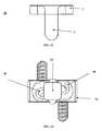
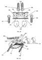
- FIG. 1Aillustrates a top, perspective (oblique) view of a vertical hemi-bracket screw locking device according to an embodiment of the invention.
- FIG. 1Billustrates a side (anterior-posterior) view of a vertical hemi-bracket screw locking device according to an embodiment of the invention.
- FIG. 1Cillustrates a side (lateral) view of a vertical hemi-bracket screw locking device according to an embodiment of the invention
- FIG. 2Aillustrates a top view of an anterior cervical intervertebral cage/BDFT screw construct according to an embodiment of the invention.
- FIG. 2Billustrates a bottom, perspective (bottom isometric) view of an anterior cervical intervertebral cage/BDFT screw construct according to an embodiment of the invention.
- FIG. 2Cillustrates a side view of an anterior cervical intervertebral cage/BDFT screw construct according to an embodiment of the invention.
- FIG. 2Dillustrates a front, perspective (front isometric) view of an anterior cervical intervertebral cage/BDFT screw construct according to an embodiment of the invention.
- FIG. 2Eillustrates a top, perspective, partially exploded (bottom isometric) view of an anterior cervical intervertebral cage/BDFT screw construct according to an embodiment of the invention.
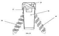
- FIG. 2Fillustrates a side, perspective, exploded view of an anterior cervical intervertebral cage/BDFT screw construct with internalized angled screw guides according to an embodiment of the invention.
- FIG. 2Gillustrates a top, perspective, exploded (top isometric) view of an anterior cervical intervertebral cage/BDFT screw construct with visualized internalized angled screw guides according to an embodiment of the invention.
- FIG. 3Aillustrates a top view of an anterior lumbar intervertebral cage/BDFT screw construct according to an embodiment of the invention.
- FIG. 3Billustrates a bottom view of an anterior lumbar intervertebral cage/BDFT screw construct according to an embodiment of the invention.
- FIG. 3Cillustrates a front, perspective view of an anterior lumbar intervertebral cage/BDFT screw construct according to an embodiment of the invention.
- FIG. 3Dillustrates a side, perspective view of an anterior lumbar intervertebral cage/BDFT screw construct according to an embodiment of the invention.
- FIG. 3Eillustrates a side, perspective view of an anterior lumbar intervertebral cage/BDFT screw construct according to an embodiment of the invention.
- FIG. 3Fillustrates a top, partially exploded view of an anterior lumbar intervertebral cage/BDFT screw construct according to an embodiment of the invention.
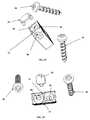
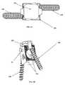
- FIG. 3Gillustrates a perspective, exploded view of an anterior lumbar intervertebral cage/BDFT screw construct according to an embodiment of the invention.
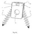
- FIG. 4Aillustrates a top view of a posterior lumbar rectangularly designed intervertebral cage/BDFT construct according to an embodiment of the invention.
- FIG. 4Billustrates a front, perspective view of a posterior lumbar rectangularly designed intervertebral cage/BDFT construct according to an embodiment of the invention.
- FIG. 4Cillustrates a side, perspective view of a posterior lumbar rectangularly designed intervertebral cage/BDFT construct according to an embodiment of the invention.
- FIG. 4Dillustrates a front, perspective view of a posterior lumbar rectangularly designed intervertebral cage/BDFT construct according to an embodiment of the invention.
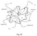
- FIG. 4Eillustrates a top, perspective, partially exploded view of a posterior lumbar rectangularly designed intervertebral cage/BDFT construct according to an embodiment of the invention.
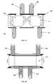
- FIG. 4Fillustrates a top, perspective, exploded view of a posterior lumbar rectangularly designed intervertebral cage/BDFT construct according to an embodiment of the invention.
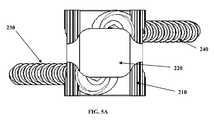
- FIG. 5Aillustrates a top view of a posterior lumbar elliptically designed intervertebral cage/BDFT construct according to an embodiment of the invention.
- FIG. 5Billustrates a front, perspective view of a posterior lumbar elliptically designed intervertebral cage/BDFT construct according to an embodiment of the invention.
- FIG. 5Cillustrates a side view of a posterior lumbar elliptically designed intervertebral cage/BDFT construct according to an embodiment of the invention.
- FIG. 5Dillustrates a front, perspective (front isometric) view of a posterior lumbar elliptically designed intervertebral cage/BDFT construct according to an embodiment of the invention.
- FIG. 5Eillustrates a top, perspective, partially exploded view of a posterior lumbar elliptically designed intervertebral cage/BDFT construct according to an embodiment of the invention.
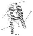
- FIG. 5Fillustrates a top, perspective, exploded view of a posterior lumbar elliptically designed intervertebral cage/BDFT construct according to an embodiment of the invention.
- FIG. 6Aillustrates a perspective view of an intervertebral cage construct according to an embodiment of the invention.
- FIG. 6Billustrates another perspective view of an intervertebral cage construct according to an embodiment of the invention.
- FIGS. 6C (i) and 6 C(ii)illustrate top, perspective view of an intervertebral cage construct according to an embodiment of the invention.
- FIG. 6Dillustrates a top, perspective, exploded view of a positioning tool/screw guide/box expander.
- FIG. 6Eillustrates a superior oblique perspective view of the positioning tool/drill guide/box expander component.
- FIGS. 1A-6Eexemplary embodiments of the invention will now be described.
- FIGS. 1A-6Ethe above described problems of the conventional art can be solved in the cervical, thoracic and lumbosacral spines by insertion into the denuded intervertebral disc space multiple embodiments of a bi-directional fixating transvertebral (BDFT) screw/cage apparatus.
- BDFTbi-directional fixating transvertebral
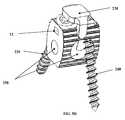
- FIGS. 1A-1Cillustrate three-dimensional views of an exemplary embodiment of a vertical hemi-bracket 20 .
- the bracket 20drapes over the screw heads (or at least a portion thereof) of screws 30 , 40 ( FIGS. 2A-5F ) and is secured to (e.g., snaps into or onto) a portion of a cage 10 , 110 , 210 ( FIGS. 2A-5F ) thereby preventing screws 30 , 40 from backing out of the cage 10 , 110 , 210 .
- the bracket 20can include a base 1 with arms 3 attached to the base 1 .
- the arms 3 a , 3 bcan extend away from the base 1 such that cage 10 , 110 , 210 interposes the arm 3 a , 3 b when the bracket 20 is engaged with the cage 10 , 110 , 210 .
- the arms 3can be attached on opposite sides/ends of the base 1 .
- the arms 3can be attached anywhere along the base 1 .
- the arms 3can include, for example, a superior arm 3 a and an inferior arm 3 b (e.g., a first arm and a second arm).
- one or more armscan be provided on either side of the base 1 .
- a first arm(e.g., 3 a ) can extend from a first side of the base 1 and a second arm (e.g., 3 b ) can extend from a second side (opposite side) of the base 1 .
- a number of arms on the first side of the base 1can be different from a number of arms on the second side of the base 1 .
- two armscan extend from a first side of the base 1 and a single arm can extend from a second side (opposite side) of the base 1 , or two arms from a first side of the base 1 and three arms from a second side (opposite side) of the base 1 , etc.
- Other numbers of arms and arrangementsare possible within the spirit and scope of the invention.
- the superior arm 3 a and inferior arm 3 bcan snap onto or snap-lock into the base 1 .
- the superior arm 3 a and inferior arm 3 bcan be resilient or flexible such that the arms 3 a , 3 b can be secured to the base 1 by the resilient arms pressing against the sides of the cage 10 , 110 , 210 .
- the arms 3 a , 3 bcan be secured by frictional forces or by corresponding engaging features formed on a part of the arms 3 a , 3 b and/or the cage 10 , 110 , 210 .
- each of the superior arm 3 a and inferior arm 3 bcan snap-lock into indentations 70 , 194 , 290 of the superior and inferior walls of the cage 10 ( FIGS. 2A-5F ), respectively.
- each of the superior arm 3 a and inferior arm 3 bcan include a medial protuberance 5 emanating and projecting from an inferior aspect of one or more of the arms 3 a , 3 b .
- the protuberances 5can snap into corresponding cage indentations 70 , 194 , 290 ( FIGS. 2A-5F ), thereby locking the bracket 20 on the cage 20 , 110 , 210 and preventing screws 30 , 40 from backing out of the cage 10 , 110 , 210 .
- a portion of the superior arm 3 a and inferior arm 3 bcan engage a portion of ridges 50 formed on the superior and inferior surfaces or edges of the lumbar cage 10 .
- FIGS. 2A-2Gillustrate three-dimensional views of an embodiment of an exemplary anterior cervical intervertebral cage/BDFT construct 10 .
- the top portion of the cage 10has indentations 70 that are on the upper superior and inferior walls midway between the two internalized screw guides/screws 80 , 90 ( FIGS. 2E-2G ).
- the vertical hemi bracket 20snaps into these indentations 70 .
- the cage 10also can include indentations or slots 12 on both side surfaces of the cage 10 for insertion of a prong of an implantation tool (see example cage and tool in FIG. 6D ; the cage 10 can engage the tool in a similar manner), and more particularly, that engage the distal medial oriented male protuberance of a lateral griper prong of an implantation tool.
- the indentations 70are formed on difference side surfaces from the indentations 12 , for example, to avoid interference with the insertion tool accessing the indentations 70 of the cage.
- the indentations 70 and the indentations 12can be formed on a same side surface.
- the indentations 70can be formed at locations other than midway between the screw guides.
- the indentations 70can have a variety of shapes and depths.
- the indentations 70can have a shape corresponding to a shape of a medial protuberance 5 emanating and projecting from an inferior aspect of one or more of the arms 3 a , 3 b .
- the size and shape of the indentations 70can be different from the medial protuberance 5 of the arms 3 a , 3 b.
- a side surface of the cage 10can be elliptically contoured when viewed from the side ( FIG. 1C ) to fit into the bi-concave cervical disc space.
- the embodimentincludes two screws 30 , 40 .
- a first screw 30is oriented rostrally (superiorly) and a second screw 40 is oriented caudally (inferiorly).
- the cage 10can include a cavity 60 for bone product placement.
- the cage 10can also include two built in internalized screw/drill guides 80 , 90 (e.g., having approximately a 25 degree angulation; in other embodiments, the angulation can be up to 40 degrees), one for each screw 30 , 40 , which orient the screws 30 , 40 bi-directionally in opposite directions ( FIGS. 2E-2G ).
- the cageincludes at least one screw guide 80 or 82 having a predetermined trajectory (e.g., preferably having a 25 degree angulation) that may make placement of all screws equally facile, more amenable to multi-level placement, and may diminish the need for external drill guides.
- the cageincludes at least two screw guides 80 , 82 having a predetermined trajectory (e.g., preferably having a 25 degree angulation) that may make placement of all screws equally facile, more amenable to multi-level placement, and may diminish the need for external drill guides.
- the cagecan include a screw guide 80 , 82 having another predetermined trajectory, such as an angulation of substantially 25 degrees (e.g., an angulation ranging from 20 degrees to 30 degrees).
- the cagecan include a screw guide 80 , 82 having another predetermined trajectory, such as an angulation ranging from 20 degrees to 25 degrees, an angulation ranging from 25 degrees to 30 degrees, an angulation ranging from 25 degrees to 35 degrees, an angulation ranging from 25 degrees to 35 degrees, an angulation ranging from 20 degrees to 40 degrees, an angulation ranging from 25 degrees to 40 degrees, etc.
- the embodiments of the cagecan include one or more screw/drill guides 80 , 82 having different angles and/or different positions within the cage.
- the cage 10can include a screw guide tunnel exit 13 adjacent to the bone cavity 60 ( FIG. 2D ).
- the screw guide tunnelcan be configured to narrow along the length of the tunnel in a direction of descent into the cage 10 .
- the internalized screw/drill guides 80 , 90can have different degrees of angulation and/or different positions within the cage 10 .
- the built in tunnels of the screw guides 80 , 90provide an important advantage of ensuring that only a single prescribed angled trajectory is possible for transvertebral screw placement.
- the built in tunnelsnarrow (cone down) going downward. This facilitates the locking of the screw head to the top of the cage even in the absence of the locking mechanism described herein.
- Embodiments of the intervertebral cages 10can be designed with internalized screw/drill guides 80 , 90 with different angles and/or different positions within the cage.
- the angle and size of the screws 30 , 40make them amenable to single or multi-level placement.
- the superior and inferior surfaces or edges of the lumbar cage 10can include ridges 50 or the like to facilitate integration and fusion with superior and inferior vertebral bodies. Any other method of bone integration may be used, such as, e.g., spikes in varying sizes and geometric arrays.
- the embodimentcan include a vertical hemi-bracket 20 which can be, for example, snapped into the superior and inferior upper wall indentations 70 in between the two screws guides 80 , 90 located on top of the cage 10 .
- the vertical hemi-bracket 20can be manufactured from a variety of materials, such as titanium.
- the vertical hemi-bracket 20which covers the medial aspect or head of both screws 30 , 40 (or a portion thereof), and when snapped into the cage indentations 70 prevents screw back out or pull out from the tunnels of the cage.
- FIGS. 3A-3Gillustrate three-dimensional views of an exemplary embodiment of an anterior lumbar intervertebral cage/BDFT construct.
- the cage 110includes indentations 194 on the upper superior and inferior walls of the top portion of the cage 110 midway between each of the two adjacent internalized screw guides 190 , 192 ( FIGS. 3F-3G ).
- the two vertical hemi brackets 120can snap into each of the indentations 194 such that there is one bracket 120 , for each pair of adjacent screws (i.e. one for screws 130 , 140 , and one for screws 150 , 160 ).
- the screws 130 , 140 and screws 150 , 160are locked into the tunnels of the cage 110 with the two hemi-brackets 120 .
- the cage 110can include additional indentations 12 on both side surfaces for insertion of prongs of an implantation tool. Further, cage 110 can be larger than the cervical cage 10 and also can include an elliptically contoured sidewalls when viewed from the side to fit into the bi-concave lumbar disc space ( FIG. 3D ).
- the cage 110may include four (4) horizontally aligned internalized screw guides 190 , 192 for four (4) screws 130 , 140 , 150 , 160 .
- the two lateral (left and right) screws 130 , 160can be oriented inferiorly, and the two middle screws 140 , 150 can be oriented superiorly.
- the axes of these guides 190 , 192 and screws 130 , 140 , 150 , 160are not perfectly horizontal with respect to each other.
- Each lateral screw guide/screwcan be obliquely oriented with respect to its adjacent medial screw guide/screw.
- the screw guide tunnel exits 13are illustrated in FIG. 3C and are in continuity (connected) with the enlarged bone cavity 180 .
- the orientations of the four screw guides 190 , 192 (and screws 130 , 140 , 150 , 160 )are selected because of their symmetry and inherent stability.
- the cage 110can include a large cavity 180 for bone product placement.
- the cage 110can include four built-in internalized screw/drill guides 190 , 192 (e.g., having an approximate 25 degree angulation; in other embodiments, the angulation can be up to 40 degrees), one for each screw 130 , 140 , 150 , 160 .
- Other embodiments of the intervertebral cage 110can be designed with internalized screw/drill guides 190 , 192 with different angles and/or different positions within the cage 110 . The angle and size of the screws 130 , 140 , 150 , 160 make them amenable to single or multi-level placement.
- the superior and inferior surfaces or edges of the cage 110can include ridges 170 or the like to facilitate integration and fusion with superior and inferior vertebral bodies.
- Other bone integration embodimentssuch as spikes can also be used.
- each vertical hemi bracket 120can be provided for each individual screw 130 , 140 , 150 , 160 , or vertical hemi bracket 120 can be provided for two or more screws 130 , 140 , 150 , 160 .
- the top of the cage 110can include indentations 194 on the superior and inferior upper sides of the cage 110 that are engaged the vertical hemi bracket 120 (e.g., by snapping a portion of the bracket into the indentation 194 ).
- the bracket 120can be manufactured from a variety of materials, such as bio-compatible materials, such as titanium.
- each of the screws 130 , 140 , 150 , 160is locked in a final position by a final turn of the screw when the screw head is flush with the surface of the cage 110 .
- the narrowing of the internal screw guides 190 , 192can act as an initial preliminary screw locking mechanism by hugging the top of the screw/screw head interface (e.g., at its junction with the screw head).
- One vertical hemi-bracket 120covers the medial aspect (or portion thereof) of the first two screws, 130 , 140
- another vertical hemi bracket 120covers the medial aspect (or portion thereof) of the third and fourth screws 150 , 160 .
- the internal screw guide tunnels 190 , 192can be formed to narrow along a length of the screw guide in a direction of descent into the screw guides, thereby providing a preliminary first locking mechanism when the screws 130 , 140 , 150 , 160 engage the screw guides and are countersunk into the top of the cage 110 .
- the exemplary embodiments of the bracket 120which are locked into the cage 110 and cover at least a portion of the screw heads, can provide a secondary additive locking mechanism in combination with the first locking mechanism, thereby definitively preventing screw back out.
- only the exemplary embodiments of the bracket 120which is locked into the cage 110 and covers the screw heads (or a part of the screw heads), may be provided to function as a primary locking mechanism for definitively preventing screw back out.
- the exemplary embodimentsare an evolutionary advance and improvement to the apparatus illustrated in the aforementioned related applications of Applicants, and are quite unique and different from all other conventional locking mechanisms used for other types of anterior lumbar cages.
- a known conventional devicethat relates to anterior placed lumbar implants with perforating screws.
- Such possible conventional devicesmay include a horseshoe implant having a plurality of cylindrical holes with smooth inner surfaces and comprise only one stop for the heads of the bone screws to be inserted into them. The placement of five cylindrical holes is oriented within the cage in a non-symmetric manner.
- the exemplary embodimentsdiffer in many substantial ways from the conventional devices.
- the exemplary embodimentsprovide a symmetric orientation of the screw holes, as well as a screw locking mechanism.
- the exemplary embodimentsalso provide an angulation/trajectory (e.g., an approximate twenty five degree angulation/trajectory) for preventing pull-out or back-out of the screws that would make placement of all screws in a manner which would lead to maximum stability of the construct within the vertebral space, and obviate the need for external drill guides, and surgeon trajectory angulation guess work.
- multiple embodiments of lumbar intervertebral implantsare presented which include one with internally threaded bore holes, another embodiment with a front plate mounted at the front surface of the implant, and another embodiment with the front place displaceably configured to move vertically relative to the implant.
- such devicesmay provide preferred borehole axes of 35-55 degrees.
- These conventional devicesmay have four screw perforations that are not aligned four in a row. Two of the screw holes are laterally placed on the left, one on top of each other, the top one with a superior trajectory, and the bottom with an inferior trajectory. Likewise, two perforations are placed on the right, one on top of each other, the top one with a superior trajectory and the bottom one with an inferior trajectory.
- the disclosed screw locking mechanismis a screw with an external thread matching the internal borehole thread, or spiral springs.
- the anterior lumbar construct of the exemplary embodimentsdiffers in many substantial ways from the conventional devices.
- the exemplary embodimentsinclude a single cage construct with four (4) internalized drill guides arranged horizontally in a row.
- the lateral screw guides/screwsare obliquely oriented with the respect to their adjacent medial screw guides/screws.
- the middle two screwsare oriented superiorly, and the lateral left and right screws are oriented inferiorly.
- This symmetric alignment of screws and orientations within the superior and inferior vertebral bodiese.g., two middle superiorly projecting screws, and two laterally projecting inferior screws) make the fixation to the superior and inferior vertebral bodies much more symmetric and thus more stable, thereby preventing subsidence.
- the cageincludes a screw guide having a predetermined trajectory (e.g., an approximate trajectory of 25 degrees to 40 degrees) that makes placement of all screws equally facile, more amenable to multi-level placement, and diminishes the need for external drill guides.
- a screw guidehaving a predetermined trajectory (e.g., an approximate trajectory of 25 degrees to 40 degrees) that makes placement of all screws equally facile, more amenable to multi-level placement, and diminishes the need for external drill guides.
- the exemplary screw locking mechanismis unique and differs substantially from the conventional approach of matching screw/cage threads or spiral springs.
- FIGS. 4A-4Fillustrate three-dimensional views of an exemplary embodiment of a posterior lumbar rectangular intervertebral cage/BDFT construct.
- the top portion of the cage 210includes indentations 290 that are positioned on the upper superior and inferior walls midway between the two internalized screw guides 270 , 280 ( FIG. 4F ).
- the vertical hemi bracket 220snaps into these indentations 290 .
- the cage 210also includes additional indentations 12 on both side surfaces of the construct for the prong placement of an implantation tool.
- the screws 230 , 240perforate and orient in opposing superior and inferior directions.
- the cage 210can include a cavity 250 for bone product placement.
- a side surface of the cage 210can be elliptically contoured when viewed from the side ( FIG. 4C ) to fit into the bi-concave cervical disc space.
- the top and bottom portions of the rectangular cage 210can be elliptically contoured to naturally fit into the bi-concave intervertebral disc space ( FIG. 4C ).
- the top portion of the cagecan be square-shaped with equal width and length.
- the depth dimension of the cage 210far exceeds its width. The width is very narrow to prevent nerve root retraction/injury when being placed posteriorly.
- the cage 210can also include built-in internalized screw/drill guides 270 , 280 having a predetermined angled trajectory (e.g., having an approximate 25 to 40 degree angulation), and their axes are not horizontal, but oblique one to the other and very close to each other ( FIG. 4F ).
- Each screw/drill guides 270 , 280can occupy one corner of a square, obliquely oriented one to the other ( FIGS. 4A and 4F ). This is necessary to achieve proper screw angulation, trajectory and bone penetration in a narrow posterior lumbar interspace.
- the intervertebral cages 210can be designed with internalized screw/drill guides 270 , 280 with different angles and/or different positions within the cage 210 . Because the tunnel of the screw guide 270 , 280 narrows (cones down), when the screw 230 , 240 is countersunk on top of the cage 210 , the screw 230 , 240 can be preliminarily locked, even in the absence of this locking mechanism.
- the cage 210can include the narrowing tunnel and/or bracket 220 for preventing backing out of the screws.
- the angle and size of the screws 230 , 240make them amenable to single or multi-level placement.
- a screw guide exit tunnelcan be formed adjacent to the bone cavity 250 .
- the superior and inferior surfaces or edgescan include ridges or the like to facilitate integration and fusion with superior and inferior vertebral bodies.
- the surfacescould alternatively or in supplement, have additional bone integration mechanisms, e.g. spikes having various sizes and arrangements.
- One of these constructsis placed posteriorly into the intervertebral space either on the left side, the right side, or both sides.
- An embodimentcan also include a cage 210 which includes a vertical hemi bracket locking mechanism 220 that can be, for example, snapped into the indentations 290 on the upper aspects of the superior and inferior sides of the cage 210 .
- the vertical hemi bracket locking mechanism 220can be manufactured from a variety of materials, such as bio-compatible materials, such as titanium.
- each of the first screw member 230 and the second screw member 240is locked in a final position by a final turn of the screw when the screw head is flush with the surface of the cage 210 .
- the narrowing of the internal screw guides 270 , 280can act as an initial preliminary screw locking mechanism.
- the vertical hemi-bracket 220 covering the medial aspect (or a portion thereof) of both screws 230 , 240 when snapped into the cage indentations 290can prevent screw back out or pull out.
- FIGS. 5A-5Fillustrates three-dimensional views of an exemplary embodiment of a posterior lumbar elliptical intervertebral cage/BDFT construct.
- the top portion of the cage 210includes indentations 290 that are positioned on the upper superior and inferior walls midway between the two internalized screw guides/screws 270 , 280 ( FIG. 5F ).
- the vertical hemi bracket 220snaps into these indentations 290 .
- the cage 210also includes additional indentations 12 on both side surfaces of the construct for the prong placement of an implantation tool.
- the screws 230 , 240perforate and orient in opposing superior and inferior directions.
- the cage 210can include a cavity 250 for bone product placement.
- the entire body (or at least the side walls) of the cage 210is elliptical when viewed from the side ( FIG. 5C ), as opposed to the top and bottom portions of the rectangular cage 210 described in the previous embodiment ( FIG. 4C ).
- the cage 210can be contoured to naturally fit into the bi-concave intervertebral disc space ( FIG. 5C ).
- the cage 210can also include built-in internalized screw/drill guides 270 , 280 having a predetermined angled trajectory (e.g., having an approximate 25-40 degree angulation), and their axes are not horizontal or vertical, but oblique one to the other and very close to each other.
- Each screw guide/screwoccupies one corner of a square, obliquely oriented one to the other ( FIGS. 5A and 5F ). In this manner, the exemplary embodiment can achieve proper screw angulation, trajectory, and bone penetration in so narrow a posterior lumbar interspace.
- One of the screw guidescan be angled rostrally (superiorly) (e.g., screw guide 270 ) and the other caudally (inferiorly) (e.g., screw guide 280 ).
- the intervertebral cages 210can be designed with internalized screw/drill guides 270 , 280 with different angles and/or different positions within the cage 210 .
- the tunnel of the screw guide 270 , 280narrows (cones down) and hugs the screw(s) 230 , 240 at the screw-screw head interface such that, when the screw is countersunk on top of the cage 210 , the screw(s) 230 , 240 can be preliminarily locked, even in the absence of an additional locking mechanism.
- the exemplary embodiments of the bracket 220which are locked into the cage 210 and cover at least a portion of the screw heads, can provide a secondary additive locking mechanism in combination with the first locking mechanism provided by the screw guides, thereby definitively preventing screw back out.
- bracket 220which is locked into the cage 210 and covers the screw heads (or a part of the screw heads), may be provided to function as a primary locking mechanism for definitively preventing screw back out.
- the angle and size of the screws 230 , 240make them amenable to single or multi-level placement.
- the screw guide exit tunnel 13 adjacent to the bone cavity 250is illustrated in FIG. 5B .
- the superior and inferior surfaces or edgescan include ridges or the like to facilitate integration and fusion with superior and inferior vertebral bodies.
- One of these constructsis placed posteriorly into the intervertebral space either on the left side, the right side, or both sides.
- the embodimentcan include a cage 210 which includes a vertical hemi bracket locking mechanism 220 that can be, for example, snapped into the indentations 290 on the upper aspects of the superior and inferior sides of the cage 210 .
- the vertical hemi bracket locking mechanism 220can be manufactured from a variety of materials, such as titanium.
- the exemplary embodiment of this novel intervertebral cage 210is an evolutionary compliment to the apparatus illustrated in the aforementioned related applications.
- the novel cage 210also is quite unique and different from other conventional locking mechanisms used for other known cervical and lumbar anterior or posterior plate screws. No other conventional posterior lumbar intervertebral cage BDFT/screw constructs are known.
- Anterior cervical spine placement of the intervertebral cage/BDFT screw construct 10( FIG. 2 ) can be implanted via previously described techniques for anterior cervical discectomy and fusion. Some but not all of these techniques include, open, microscopic, closed endoscopic or tubular. Fluoroscopic or any other form of visualized guidance can be used for this procedure.
- the patientis placed in a supine position.
- An incisionis made overlying the intended disc space or spaces, and the anterior spine is exposed.
- a discectomyis performed and the endplates exposed.
- the disc heightis measured and an anterior cervical intervertebral cage of the appropriate disc height, width and depth is selected.
- the central cavity 60is packed with bone fusion material, autologous bone graft, allograft, alone or in combination with any commercially available bone fusion promoting product.
- the cage 10is then inserted into the midline of the anterior disc space routinely until it is flush or countersunk relative to the vertebral body above and below.
- the BDFT screws 30 , 40are then inserted into the internalized rostrally (superiorly) and caudally (inferiorly) angled screw guides 80 , 90 .
- a drill with or without a drill guidecan be used to prepare for screw placement. This is not absolutely necessary.
- self-drilling/self-tapping screws 30 , 40 of the appropriately selected lengthscan be directly screwed into the vertebral bodies once placed into the internalized drill-guided angled tunnels.
- the cage's screw guides 80 , 90which have internalized tunnels, direct the screws 30 , 40 into the superior and inferior vertebral bodies in the predetermined angle of the internalized tunnels. There is no other angled trajectory other than that which is built into the internalized screw guide/tunnel of the cage 10 that the screw 30 , 40 can be oriented in.
- the BDFT screws 30 , 40can then be locked into their final positions.
- each of the BDFT screws 30 , 40are turned they penetrate and engage the bone until they are locked in a final position by its final turn when the screw head is flush with the surface of the cage 10 .
- the vertical hemi bracket 20is then snapped into the upper superior and inferior cage indentations 70 covering the medial aspect of both screws.
- Anterior or anteriolateral placement of thoracic or lumbar spine intervertebral cage/BDFT screw constructs 110can be implanted via previously described surgical techniques for anterior lumbar discectomy, and transthoracic, anterior-lateral thoracic discectomy. Some but not all of these techniques include, open, microscopic, closed endoscopic or tubular. Fluoroscopic or any other form of visualized guidance can be used for this procedure.
- a discectomyis performed and the endplates exposed.
- the disc heightis measured and an anterior lumbar (or thoracic) intervertebral cage 110 of the appropriate disc height, width and depth is selected.
- the central cavity 180is packed with bone fusion material, autologous bone graft, allograft, alone or in combination with any commercially available bone fusion promoting product.
- the cage 110is then inserted into the midline of the anterior disc space routinely until it is flush or countersunk relative to the vertebral body above and below.
- the four BDFT screws 130 , 140 , 150 , 160are then inserted into the two middle internalized rostrally (superiorly) and two lateral, caudally (inferiorly) angled screw guides 190 , 192 .
- a drill with or without a drill guide 190 , 192can be used to prepare for screw placement. This is not absolutely necessary. Because the cage 110 has internalized screw guides 190 , 192 , self-drilling/self-tapping screws 130 , 140 , 150 , 160 of the appropriately selected lengths can be directly screwed into the vertebral bodies once placed into the internalized drill-guided angled tunnels.
- the cage's internalized guides 190 , 192which have internalized tunnels, direct the screws 130 , 140 , 150 , 160 into the superior and inferior vertebral bodies in the predetermined angle of the internalized tunnels. There is no other angled trajectory other than that which is built into the internalized screw guide/tunnel of the cage 110 that the screw 130 , 140 , 150 , 160 can be oriented in. Hence there is no absolute need for fluoroscopic guidance.
- the BDFT screws 130 , 140 , 150 , 160can then be locked into their final positions.
- each of the BDFT screws 130 , 140 , 150 , 160are turned, they penetrate and engage the bone until they are locked in a final position by its final turn when the screw head is flush with the surface of the cage 110 .
- One vertical hemi bracket 120is snapped into its corresponding cage indentations 194 thereby covering the medial aspects of the first two screws 130 , 140
- another vertical hemi bracket 120is snapped into its respective cage indentations 194 thereby covering the medial aspects of the third and fourth screws 150 , 160 .
- Implantation of the posterior lumbar intervertebral cage/BDFT screw constructs 210can be performed via previously described posterior lumbar interbody fusion (PLIF) or posterior transforaminal lumbar interbody fusion (TLIF) procedures.
- the procedurescan be performed open, microscopic, closed tubular or endoscopic techniques. Fluoroscopic guidance can be used with any of these procedures.
- the patientis placed in the prone position.
- a midline incisionis made for a PLIF procedure, and one or two parallel paramedian incisions or a midline incision is made for the TLIF procedure.
- a unilateral or bilateral facet sparing hemi-laminotomyis created to introduce the posterior lumbar construct into the disc space after a discectomy is performed and the space adequately prepared.
- the far lateral disc spaceis entered and a circumferential discectomy is performed.
- the disc spaceis prepared and the endplates exposed.
- the disc heightis measured and a posterior lumbar intervertebral cage/BDFT screw construct 210 ( FIGS. 4 and 5 ) of the appropriate disc height, width and depth is selected.
- the central cavity 250is packed with bone fusion material, autologous bone graft, allograft, alone or in combination with any commercially available bone fusion promoting product.
- one construct 210is placed on either right or left sides, or one construct 210 each is placed into left and right sides.
- the constructs 210are inserted such they are flush or countersunk relative to the superior and inferior vertebral bodies.
- the intervertebral space in between the constructs 210can also be packed with bone product for fusion.
- the BDFT screws 230 , 240are then inserted into internalized rostrally (superiorly) and caudally (inferiorly) angled screw guides 270 , 280 .
- a drill with or without a drill guidecan be used to prepare for screw placement. This is not absolutely necessary. Because the cage 210 has internalized screw guides 270 , 280 , self-drilling/self-tapping screws 230 , 240 of the appropriately selected lengths can be directly screwed into the vertebral bodies once placed into the internalized drill-guided/angled tunnels 270 , 280 .
- the cage's internalized guides 270 , 280which have internalized tunnels, direct the screws 230 , 240 into the superior and inferior vertebral bodies in the predetermined angle of the internalized tunnels. There is no other angled trajectory other than that which is built into the internalized screw guide/tunnel 270 , 280 of the cage 210 that the screw 230 , 240 can be oriented in. Hence, unlike posterior placement of pedicle screws there is no absolute need for fluoroscopic or expensive and cumbersome, frameless stereotactic CT guidance.
- the BDFT screws 230 , 240can then be locked into their final positions.
- the BDFT screws 230 , 240 with ratcheted screw headsare turned, the BDFT screws 230 , 240 penetrate and engage the bone until they are locked in a final position by its final turn when the screw head is flush with the surface of the cage 210 .
- the vertical hemi bracket 220is then snapped into the upper superior and inferior cage indentations 290 of the cage 210 covering the medial aspect of both screws 230 , 240 and thus preventing screw back out or pull out.
- the present inventionsmay provide effective and safe techniques that overcome the problems associated with current transpedicular based cervical, thoracic and lumbar fusion technology, as well as anterior cervical, thoracic and lumbar plating technology, and for many degenerative stable and unstable spinal diseases. These exemplary embodiments may replace much pedicle screw, and anterior plating based instrumentation in many but not all degenerative spine conditions.
- anterior and posterior lumbar intervertebral cage/BDFT screw constructsand placement of anterior cervical cage/BDFT screw constructs far exceeds that of current pedicle screw and anterior spinal plating technology.
- these deviceshave markedly significantly decreased risk of misguided screw placement and hence decreased risk of neurovascular injury, and blood loss.
- the lumbar and cervical intervertebral cage/BDFT screw constructsall would have decreased recovery time, and more rapid return to work time compared to pedicle screw, and plating technology.
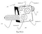
- FIGS. 6A, 6B, 6C (i), and 5 C(ii)illustrate an exemplary embodiment of exemplary cage 200 . These features are shown for example purposes, are not limited to the cage 200 , and can be incorporated into any cage according to any of the embodiments described herein. As shown in FIGS. 6C (i) and 6 C(ii), the screw guides can be positioned within four (4) quadrants I, II, III, IV.
- the intervertebral cagecan include a wall having an entry opening of the first integral screw guide and an entry opening of the second integral screw guide, wherein the wall of the cage can include four quadrants delineated by a first axis and a second axis each lying in a plane of the wall, and the first axis is at a right angle with respect to the second axis, wherein the four quadrants include a first quadrant, a second quadrant, a third quadrant, and a fourth quadrant, wherein the first quadrant and the fourth quadrant are opposed to the second quadrant and the third quadrant with respect to the first axis, and the first quadrant and the second quadrant are opposed to the third quadrant and the fourth quadrant with respect to the second axis, wherein the first quadrant is diagonally opposed to the third quadrant, and the second quadrant is diagonally opposed to the fourth quadrant, and wherein one of a majority of an area of the entry opening of the first integral screw guide is in the first quadrant and a majority
- the intervertebral cagecan include a wall having an entry opening of the first integral screw guide and an entry opening of the second integral screw guide, wherein the wall has four quadrants delineated by a first axis and a second axis each lying in a plane of the wall, and the first axis is at a right angle with respect to the second axis, wherein the four quadrants include a first quadrant, a second quadrant, a third quadrant, and a fourth quadrant, wherein the first quadrant and the fourth quadrant are opposed to the second quadrant and the third quadrant with respect to the first axis, and the first quadrant and the second quadrant are opposed to the third quadrant and the fourth quadrant with respect to the second axis, wherein the first quadrant is diagonally opposed to the third quadrant, and the second quadrant is diagonally opposed to the fourth quadrant, and wherein one of a center of the entry opening of the first integral screw guide is in the first quadrant and a center of the entry opening of the second integral screw
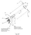
- FIG. 6Dillustrates an embodiment of an external drill/screw guide-box expander which assists in screw trajectory of the exemplary cage 200 .
- the cage 200can be a cage according to any of the embodiments described herein, or an expanding cage, in which case an expanding Allen key component can be used.
- the devicecan include, for example, an Allen key 501 (e.g., for an expandable cage), a spring 502 , a handle 503 , a gripper 504 having a gripper prong 506 , which alternatively may include a male protuberance (e.g., a medially oriented mal protuberant extension for insertion into the lateral cage slot 12 ), and a screw guide 505 .
- an Allen key 501e.g., for an expandable cage
- a spring 502e.g., for an expandable cage
- a handle 503e.g., a handle 503
- a gripper 504 having a gripper prong 506which alternatively may
- FIG. 6Eillustrates a superior oblique view of the screw guide demonstrating insertions or grooves 509 for gripper prong 506 of the gripper 504 in FIG. 6D , built-in trajectory guides 511 , 512 for insertions of screws, and an opening 514 for an Allen key, in instances in which an expandable cage is being used.
- the Allen keymay not be present when a non-adjustable cage is being used.
- the Allen keymay be present even when an adjustable cage is being used, such that the tool is universal to various types of cages.
- the gripper 504can include gripper prongs (e.g., medially oriented male protuberant extensions) 506 which insert into grooves 509 of the screw guide 505 and lateral slots (e.g., 12) of a cage, thereby perfectly aligning them.
- gripper prongse.g., medially oriented male protuberant extensions
- lateral slotse.g., 12
- a cagecan be provided that has internal screw guides which have no gaps, and furthermore an insertion tool can be provided that has an external screw guide that further precisely guides the screws through the external tool screw guide, then into the internal implant screw guide guaranteeing the precise predetermined angulation of the screws.
- the combination the internal and external screw guidescan create a long tunnel for a screw to enable a predetermined trajectory.
- an embodiment of the indentations or recesses for the screw holes in any of the exemplary cagescan be configured such that the screw heads will rest entirely within a peripheral side of a surface of the top portion of the cage (i.e., top surface).
- the direction of the screw tunnelis from an anterior surface to a posterior of the top surface of the cage (i.e., the non-adjacent side).
- the indentations or recesses for the screw holescan be configured such that the screw heads will rest entirely within the peripheral side of the top surface of the cage.
- the screw hole guidepasses through the anterior-posterior axis of the top surface.
- the guides core circumference for the screw threadis surrounded by the lateral wall masses, and surrounded by mass from the front and rear surfaces (i.e., walls) of the cage.
- the indentations or recesses for the screw holescan be configured such that a recess for the screw holes are entirely within the peripheral side of the top surface of the box.
- there is a through-hole for a screwwhich is counter-bored to keep the screw head within an outer surface boundary of the cage and in a direction to prevent the screw from avoiding the front or rear surfaces of the cage.
- the indentations or recesses for the screw holescan be configured such that a recess for the screw holes is entirely within the peripheral side of the front wall of the cage
- the tunnel for the screwsis such that when the screw first enters, the screw will be surrounded by mass from the lateral sides and mass from the upper and lower sides of the wall. The screw will exit at the posterior end of the peripheral wall.
- an embodiment of the indentations or recesses for the screw holescan be configured such that a position of the screws is suitable for posterior lumbar screw holes.
- the screw holescan be diagonal to each other along a transversal line.
- the transversal linecan be defined as the line that would diagonally intersect and bypass the space between the recess for the screw holes.
- the screw holescan be diagonally opposed and lie on a congruent angle to each other from the intersecting transversal line.
- the recess for the screw holescan be diagonal and perpendicular to each other within the outer plane.
- the recess for the screw holescan be diagonal and symmetrically constrained within the outer wall of the cage.
Landscapes
- Health & Medical Sciences (AREA)
- Orthopedic Medicine & Surgery (AREA)
- Life Sciences & Earth Sciences (AREA)
- Neurology (AREA)
- Surgery (AREA)
- Engineering & Computer Science (AREA)
- Biomedical Technology (AREA)
- General Health & Medical Sciences (AREA)
- Veterinary Medicine (AREA)
- Heart & Thoracic Surgery (AREA)
- Public Health (AREA)
- Animal Behavior & Ethology (AREA)
- Molecular Biology (AREA)
- Medical Informatics (AREA)
- Nuclear Medicine, Radiotherapy & Molecular Imaging (AREA)
- Cardiology (AREA)
- Oral & Maxillofacial Surgery (AREA)
- Transplantation (AREA)
- Vascular Medicine (AREA)
- Prostheses (AREA)
- Surgical Instruments (AREA)
Abstract
Description
Claims (91)
Priority Applications (4)
| Application Number | Priority Date | Filing Date | Title |
|---|---|---|---|
| US13/418,335US9532821B2 (en) | 2005-04-12 | 2012-03-12 | Bi-directional fixating/locking transvertebral body screw/intervertebral cage stand-alone constructs with vertical hemi-bracket screw locking mechanism |
| US15/397,198US10098678B2 (en) | 2005-04-12 | 2017-01-03 | Bi-directional fixating/locking transvertebral body screw/intervertebral cage stand-alone constructs with vertical hemi-bracket screw locking mechanism |
| US16/160,824US10842542B2 (en) | 2005-04-12 | 2018-10-15 | Spinal bone fusion system |
| US16/952,241US11759243B2 (en) | 2005-04-12 | 2020-11-19 | Spinal bone fusion system |
Applications Claiming Priority (12)
| Application Number | Priority Date | Filing Date | Title |
|---|---|---|---|
| US67023105P | 2005-04-12 | 2005-04-12 | |
| US11/208,644US7704279B2 (en) | 2005-04-12 | 2005-08-23 | Bi-directional fixating transvertebral body screws, zero-profile horizontal intervertebral miniplates, expansile intervertebral body fusion devices, and posterior motion-calibrating interarticulating joint stapling device for spinal fusion |
| US11/536,815US7846188B2 (en) | 2005-04-12 | 2006-09-29 | Bi-directional fixating transvertebral body screws, zero-profile horizontal intervertebral miniplates, total intervertebral body fusion devices, and posterior motion-calibrating interarticulating joint stapling device for spinal fusion |
| US11/842,855US7942903B2 (en) | 2005-04-12 | 2007-08-21 | Bi-directional fixating transvertebral body screws and posterior cervical and lumbar interarticulating joint calibrated stapling devices for spinal fusion |
| US12/054,335US7972363B2 (en) | 2005-04-12 | 2008-03-24 | Bi-directional fixating/locking transvertebral body screw/intervertebral cage stand-alone constructs and posterior cervical and lumbar interarticulating joint stapling guns and devices for spinal fusion |
| US201161445034P | 2011-02-21 | 2011-02-21 | |
| US201161451582P | 2011-03-10 | 2011-03-10 | |
| US201161451579P | 2011-03-10 | 2011-03-10 | |
| US13/084,543US8353913B2 (en) | 2005-04-12 | 2011-04-11 | Bi-directional fixating transvertebral body screws and posterior cervical and lumbar interarticulating joint calibrated stapling devices for spinal fusion |
| US13/103,994US9603713B2 (en) | 2005-04-12 | 2011-05-09 | Bi-directional fixating/locking transvertebral body screw/intervertebral cage stand-alone constructs and posterior cervical and lumbar interarticulating joint stapling guns and devices for spinal fusion |
| US13/401,829US9744052B2 (en) | 2005-04-12 | 2012-02-21 | Bi-directional fixating/locking transvertebral body screw/intervertebral cage stand-alone constructs |
| US13/418,335US9532821B2 (en) | 2005-04-12 | 2012-03-12 | Bi-directional fixating/locking transvertebral body screw/intervertebral cage stand-alone constructs with vertical hemi-bracket screw locking mechanism |
Related Parent Applications (5)
| Application Number | Title | Priority Date | Filing Date |
|---|---|---|---|
| US13/084,543Continuation-In-PartUS8353913B2 (en) | 2005-04-12 | 2011-04-11 | Bi-directional fixating transvertebral body screws and posterior cervical and lumbar interarticulating joint calibrated stapling devices for spinal fusion |
| US13/103,994Continuation-In-PartUS9603713B2 (en) | 2005-04-12 | 2011-05-09 | Bi-directional fixating/locking transvertebral body screw/intervertebral cage stand-alone constructs and posterior cervical and lumbar interarticulating joint stapling guns and devices for spinal fusion |
| US13/103,994ContinuationUS9603713B2 (en) | 2005-04-12 | 2011-05-09 | Bi-directional fixating/locking transvertebral body screw/intervertebral cage stand-alone constructs and posterior cervical and lumbar interarticulating joint stapling guns and devices for spinal fusion |
| US13/401,829Continuation-In-PartUS9744052B2 (en) | 2005-04-12 | 2012-02-21 | Bi-directional fixating/locking transvertebral body screw/intervertebral cage stand-alone constructs |
| US15/397,198Continuation-In-PartUS10098678B2 (en) | 2005-04-12 | 2017-01-03 | Bi-directional fixating/locking transvertebral body screw/intervertebral cage stand-alone constructs with vertical hemi-bracket screw locking mechanism |
Related Child Applications (3)
| Application Number | Title | Priority Date | Filing Date |
|---|---|---|---|
| US11/536,815Continuation-In-PartUS7846188B2 (en) | 2005-04-12 | 2006-09-29 | Bi-directional fixating transvertebral body screws, zero-profile horizontal intervertebral miniplates, total intervertebral body fusion devices, and posterior motion-calibrating interarticulating joint stapling device for spinal fusion |
| US13/084,543DivisionUS8353913B2 (en) | 2005-04-12 | 2011-04-11 | Bi-directional fixating transvertebral body screws and posterior cervical and lumbar interarticulating joint calibrated stapling devices for spinal fusion |
| US15/397,198ContinuationUS10098678B2 (en) | 2005-04-12 | 2017-01-03 | Bi-directional fixating/locking transvertebral body screw/intervertebral cage stand-alone constructs with vertical hemi-bracket screw locking mechanism |
Publications (2)
| Publication Number | Publication Date |
|---|---|
| US20130018470A1 US20130018470A1 (en) | 2013-01-17 |
| US9532821B2true US9532821B2 (en) | 2017-01-03 |
Family
ID=47519359
Family Applications (4)
| Application Number | Title | Priority Date | Filing Date |
|---|---|---|---|
| US13/418,335Expired - LifetimeUS9532821B2 (en) | 2005-04-12 | 2012-03-12 | Bi-directional fixating/locking transvertebral body screw/intervertebral cage stand-alone constructs with vertical hemi-bracket screw locking mechanism |
| US15/397,198Expired - LifetimeUS10098678B2 (en) | 2005-04-12 | 2017-01-03 | Bi-directional fixating/locking transvertebral body screw/intervertebral cage stand-alone constructs with vertical hemi-bracket screw locking mechanism |
| US16/160,824Active2025-10-24US10842542B2 (en) | 2005-04-12 | 2018-10-15 | Spinal bone fusion system |
| US16/952,241Expired - LifetimeUS11759243B2 (en) | 2005-04-12 | 2020-11-19 | Spinal bone fusion system |
Family Applications After (3)
| Application Number | Title | Priority Date | Filing Date |
|---|---|---|---|
| US15/397,198Expired - LifetimeUS10098678B2 (en) | 2005-04-12 | 2017-01-03 | Bi-directional fixating/locking transvertebral body screw/intervertebral cage stand-alone constructs with vertical hemi-bracket screw locking mechanism |
| US16/160,824Active2025-10-24US10842542B2 (en) | 2005-04-12 | 2018-10-15 | Spinal bone fusion system |
| US16/952,241Expired - LifetimeUS11759243B2 (en) | 2005-04-12 | 2020-11-19 | Spinal bone fusion system |
Country Status (1)
| Country | Link |
|---|---|
| US (4) | US9532821B2 (en) |
Cited By (51)
| Publication number | Priority date | Publication date | Assignee | Title |
|---|---|---|---|---|
| US9788971B1 (en) | 2013-05-22 | 2017-10-17 | Nuvasive, Inc. | Expandable fusion implant and related methods |
| US20170303979A1 (en)* | 2005-04-12 | 2017-10-26 | Nathan C. Moskowitz | Bi-directional fixating/locking transvertebral body screw/intervertebral cage stand-alone constructs with vertical hemi-bracket screw locking mechanism |
| US9801734B1 (en) | 2013-08-09 | 2017-10-31 | Nuvasive, Inc. | Lordotic expandable interbody implant |
| US10195053B2 (en) | 2009-09-18 | 2019-02-05 | Spinal Surgical Strategies, Llc | Bone graft delivery system and method for using same |
| US10245159B1 (en) | 2009-09-18 | 2019-04-02 | Spinal Surgical Strategies, Llc | Bone graft delivery system and method for using same |
| US10299842B2 (en) | 2013-12-20 | 2019-05-28 | Crossroads Extremity Systems, Llc | Bone plates with dynamic elements |
| US10492841B2 (en) | 2014-07-10 | 2019-12-03 | Crossroads Extremity Systems, Llc | Bone implant and means of insertion |
| US10856997B2 (en) | 2018-02-22 | 2020-12-08 | Warsaw Orthopedic, Inc. | Expandable spinal implant system and method of using same |
| US10945725B2 (en) | 2017-02-06 | 2021-03-16 | Crossroads Extremity Systems, Llc | Implant inserter |
| US10973656B2 (en) | 2009-09-18 | 2021-04-13 | Spinal Surgical Strategies, Inc. | Bone graft delivery system and method for using same |
| US11020239B2 (en) | 2018-02-22 | 2021-06-01 | Warsaw Orthopedic, Inc. | Expandable spinal implant system and method of using same |
| US11179149B2 (en) | 2017-02-07 | 2021-11-23 | Crossroads Extremity Systems, Llc | Counter-torque implant |
| US11202626B2 (en) | 2014-07-10 | 2021-12-21 | Crossroads Extremity Systems, Llc | Bone implant with means for multi directional force and means of insertion |
| US11285014B1 (en) | 2020-11-05 | 2022-03-29 | Warsaw Orthopedic, Inc. | Expandable inter-body device, system, and method |
| USD948048S1 (en) | 2019-04-26 | 2022-04-05 | Warsaw Orthopedic, Inc. | Surgical implant |
| US11291554B1 (en) | 2021-05-03 | 2022-04-05 | Medtronic, Inc. | Unibody dual expanding interbody implant |
| US11317951B2 (en) | 2013-12-20 | 2022-05-03 | Crossroads Extremity Systems, Llc | Bone plates with dynamic elements |
| USD955579S1 (en) | 2019-04-26 | 2022-06-21 | Warsaw Orthopedic, Inc. | Surgical implant |
| US11376134B1 (en) | 2020-11-05 | 2022-07-05 | Warsaw Orthopedic, Inc. | Dual expanding spinal implant, system, and method of use |
| USD957639S1 (en) | 2013-03-15 | 2022-07-12 | Medtronic, Inc. | Implantable cardiac monitor |
| US11395743B1 (en) | 2021-05-04 | 2022-07-26 | Warsaw Orthopedic, Inc. | Externally driven expandable interbody and related methods |
| USD961081S1 (en) | 2020-11-18 | 2022-08-16 | Crossroads Extremity Systems, Llc | Orthopedic implant |
| US11517443B2 (en) | 2020-11-05 | 2022-12-06 | Warsaw Orthopedic, Inc. | Dual wedge expandable implant, system and method of use |
| US11554020B2 (en) | 2020-09-08 | 2023-01-17 | Life Spine, Inc. | Expandable implant with pivoting control assembly |
| US11564724B2 (en) | 2020-11-05 | 2023-01-31 | Warsaw Orthopedic, Inc. | Expandable inter-body device, system and method |
| US11602440B2 (en) | 2020-06-25 | 2023-03-14 | Life Spine, Inc. | Expandable implant assembly |
| US11602439B2 (en) | 2020-04-16 | 2023-03-14 | Life Spine, Inc. | Expandable implant assembly |
| US11612499B2 (en) | 2021-06-24 | 2023-03-28 | Warsaw Orthopedic, Inc. | Expandable interbody implant |
| US11638653B2 (en) | 2020-11-05 | 2023-05-02 | Warsaw Orthopedic, Inc. | Surgery instruments with a movable handle |
| US11730608B2 (en) | 2021-07-13 | 2023-08-22 | Warsaw Orthopedic, Inc. | Monoblock expandable interbody implant |
| US11766339B1 (en) | 2017-10-24 | 2023-09-26 | Omnia Medical, LLC | Multi-material multi-component spinal implant |
| US11806250B2 (en) | 2018-02-22 | 2023-11-07 | Warsaw Orthopedic, Inc. | Expandable spinal implant system and method of using same |
| US11833059B2 (en) | 2020-11-05 | 2023-12-05 | Warsaw Orthopedic, Inc. | Expandable inter-body device, expandable plate system, and associated methods |
| US11850163B2 (en) | 2022-02-01 | 2023-12-26 | Warsaw Orthopedic, Inc. | Interbody implant with adjusting shims |
| US11857432B2 (en) | 2020-04-13 | 2024-01-02 | Life Spine, Inc. | Expandable implant assembly |
| US11896494B2 (en) | 2017-07-10 | 2024-02-13 | Life Spine, Inc. | Expandable implant assembly |
| US11963881B2 (en) | 2020-11-05 | 2024-04-23 | Warsaw Orthopedic, Inc. | Expandable inter-body device, system, and method |
| US11986398B2 (en) | 2013-03-13 | 2024-05-21 | Life Spine, Inc. | Expandable implant assembly |
| US12042395B2 (en) | 2019-06-11 | 2024-07-23 | Life Spine, Inc. | Expandable implant assembly |
| US12059183B2 (en) | 2020-07-31 | 2024-08-13 | Crossroads Extremity Systems, Llc | Bone plates with dynamic elements and screws |
| US12121453B2 (en) | 2020-11-05 | 2024-10-22 | Warsaw Orthopedic, Inc. | Dual wedge expandable implant with eyelets, system, and method of use |
| US12138179B2 (en) | 2019-06-10 | 2024-11-12 | Life Spine, Inc. | Expandable implant assembly with compression features |
| US12171439B2 (en) | 2020-11-05 | 2024-12-24 | Warsaw Orthopedic, Inc. | Protected drill |
| US12193948B2 (en) | 2013-03-13 | 2025-01-14 | Life Spine, Inc. | Expandable implant assembly |
| US12239544B2 (en) | 2020-11-05 | 2025-03-04 | Warsaw Orthopedic, Inc. | Rhomboid shaped implants |
| US12268614B2 (en) | 2021-06-24 | 2025-04-08 | Warsaw Orthopedic, Inc. | Interbody implant with adjusting shims |
| US12295865B2 (en) | 2021-06-24 | 2025-05-13 | Warsaw Orthopedic, Inc. | Expandable interbody implant and corresponding inserter |
| US12318308B2 (en) | 2020-11-05 | 2025-06-03 | Warsaw Orthopedic, Inc. | Dual expandable inter-body device |
| US12336917B2 (en) | 2020-05-15 | 2025-06-24 | Life Spine, Inc. | Steerable implant assembly |
| US12414863B2 (en) | 2021-06-24 | 2025-09-16 | Warsaw Orthopedic, Inc. | Expandable interbody implant and corresponding surgical tool |
| US12440349B2 (en) | 2022-02-04 | 2025-10-14 | Warsaw Orthopedic, Inc. | Expandable interbody implant and breakoff screw |
Families Citing this family (31)
| Publication number | Priority date | Publication date | Assignee | Title |
|---|---|---|---|---|
| US8597360B2 (en) | 2004-11-03 | 2013-12-03 | Neuropro Technologies, Inc. | Bone fusion device |
| US7846188B2 (en) | 2005-04-12 | 2010-12-07 | Moskowitz Nathan C | Bi-directional fixating transvertebral body screws, zero-profile horizontal intervertebral miniplates, total intervertebral body fusion devices, and posterior motion-calibrating interarticulating joint stapling device for spinal fusion |
| US9848993B2 (en) | 2005-04-12 | 2017-12-26 | Nathan C. Moskowitz | Zero-profile expandable intervertebral spacer devices for distraction and spinal fusion and a universal tool for their placement and expansion |
| US7704279B2 (en) | 2005-04-12 | 2010-04-27 | Moskowitz Mosheh T | Bi-directional fixating transvertebral body screws, zero-profile horizontal intervertebral miniplates, expansile intervertebral body fusion devices, and posterior motion-calibrating interarticulating joint stapling device for spinal fusion |
| US7942903B2 (en) | 2005-04-12 | 2011-05-17 | Moskowitz Ahmnon D | Bi-directional fixating transvertebral body screws and posterior cervical and lumbar interarticulating joint calibrated stapling devices for spinal fusion |
| US7972363B2 (en) | 2005-04-12 | 2011-07-05 | Moskowitz Ahmnon D | Bi-directional fixating/locking transvertebral body screw/intervertebral cage stand-alone constructs and posterior cervical and lumbar interarticulating joint stapling guns and devices for spinal fusion |
| US9744052B2 (en) | 2005-04-12 | 2017-08-29 | Nathan C. Moskowitz | Bi-directional fixating/locking transvertebral body screw/intervertebral cage stand-alone constructs |
| US11903849B2 (en) | 2005-04-12 | 2024-02-20 | Moskowitz Family Llc | Intervertebral implant and tool assembly |
| US7854765B2 (en) | 2006-04-20 | 2010-12-21 | Moskowitz Mosheh T | Electronically controlled artificial intervertebral disc with motor assisted actuation systems |
| US9526525B2 (en) | 2006-08-22 | 2016-12-27 | Neuropro Technologies, Inc. | Percutaneous system for dynamic spinal stabilization |
| EP2547292B1 (en) | 2010-03-16 | 2019-04-24 | Pinnacle Spine Group, LLC | Ntervertebral implants and graft delivery systems |
| WO2013023096A1 (en) | 2011-08-09 | 2013-02-14 | Neuropro Technologies, Inc. | Bone fusion device, system and method |
| US9358123B2 (en) | 2011-08-09 | 2016-06-07 | Neuropro Spinal Jaxx, Inc. | Bone fusion device, apparatus and method |
| US10420654B2 (en) | 2011-08-09 | 2019-09-24 | Neuropro Technologies, Inc. | Bone fusion device, system and method |
| US9539109B2 (en) | 2011-09-16 | 2017-01-10 | Globus Medical, Inc. | Low profile plate |
| US9237957B2 (en)* | 2011-09-16 | 2016-01-19 | Globus Medical, Inc. | Low profile plate |
| US9149365B2 (en)* | 2013-03-05 | 2015-10-06 | Globus Medical, Inc. | Low profile plate |
| US9380932B1 (en) | 2011-11-02 | 2016-07-05 | Pinnacle Spine Group, Llc | Retractor devices for minimally invasive access to the spine |
| US9693876B1 (en)* | 2012-03-30 | 2017-07-04 | Ali H. MESIWALA | Spinal fusion implant and related methods |
| US10159583B2 (en) | 2012-04-13 | 2018-12-25 | Neuropro Technologies, Inc. | Bone fusion device |
| US9532883B2 (en) | 2012-04-13 | 2017-01-03 | Neuropro Technologies, Inc. | Bone fusion device |
| WO2014159739A1 (en) | 2013-03-14 | 2014-10-02 | Pinnacle Spine Group, Llc | Interbody implants and graft delivery systems |
| CA2906531C (en) | 2013-03-15 | 2020-10-06 | Neuropro Technologies, Inc. | Bodiless bone fusion device, apparatus and method |
| US10603187B2 (en) | 2013-07-17 | 2020-03-31 | Aesculap Implant Systems, Llc | Spinal interbody device, system and method |
| US8776456B1 (en)* | 2013-10-21 | 2014-07-15 | Sunmodo Corporation | Solar panel tile roof mounting device |
| US9364341B2 (en)* | 2014-01-09 | 2016-06-14 | Warsaw Orthopedic, Inc. | Spinal implant system and method |
| FR3048176A1 (en) | 2016-02-26 | 2017-09-01 | Ldr Medical | SPINAL ARTHRODESIS IMPLANT SYSTEM |
| US10729560B2 (en) | 2017-01-18 | 2020-08-04 | Neuropro Technologies, Inc. | Bone fusion system, device and method including an insertion instrument |
| US10973657B2 (en) | 2017-01-18 | 2021-04-13 | Neuropro Technologies, Inc. | Bone fusion surgical system and method |
| US10111760B2 (en) | 2017-01-18 | 2018-10-30 | Neuropro Technologies, Inc. | Bone fusion system, device and method including a measuring mechanism |
| US10213321B2 (en) | 2017-01-18 | 2019-02-26 | Neuropro Technologies, Inc. | Bone fusion system, device and method including delivery apparatus |
Citations (122)
| Publication number | Priority date | Publication date | Assignee | Title |
|---|---|---|---|---|
| US2360942A (en) | 1943-01-23 | 1944-10-24 | Jack I Ellerstein | Drill guide |
| US4064881A (en) | 1975-06-06 | 1977-12-27 | Rocket Of London Limited | Surgical clip applicator |
| US4554914A (en) | 1983-10-04 | 1985-11-26 | Kapp John P | Prosthetic vertebral body |
| US4599086A (en) | 1985-06-07 | 1986-07-08 | Doty James R | Spine stabilization device and method |
| US4636217A (en) | 1985-04-23 | 1987-01-13 | Regents Of The University Of Minnesota | Anterior spinal implant |
| US4904261A (en) | 1987-08-06 | 1990-02-27 | A. W. Showell (Surgicraft) Limited | Spinal implants |
| US4960420A (en) | 1988-08-23 | 1990-10-02 | Marlowe Goble E | Channel ligament clamp and system |
| US4997432A (en) | 1988-03-23 | 1991-03-05 | Waldemar Link Gmbh & Co. | Surgical instrument set |
| US5005749A (en) | 1988-07-01 | 1991-04-09 | United States Surgical Corp. | Anastomosis surgical stapling instrument |
| US5062850A (en) | 1990-01-16 | 1991-11-05 | University Of Florida | Axially-fixed vertebral body prosthesis and method of fixation |
| US5123926A (en) | 1991-02-22 | 1992-06-23 | Madhavan Pisharodi | Artificial spinal prosthesis |
| US5290312A (en) | 1991-09-03 | 1994-03-01 | Alphatec | Artificial vertebral body |
| US5405391A (en) | 1993-02-16 | 1995-04-11 | Hednerson; Fraser C. | Fusion stabilization chamber |
| US5413583A (en) | 1992-05-21 | 1995-05-09 | Ethicon, Inc. | Force limiting arrangement for needle holder for endoscopic surgery |
| US5454819A (en) | 1994-03-17 | 1995-10-03 | Nusurg Medical, Inc. | Spring biased laparoscopic surgical needle holder |
| US5514180A (en) | 1994-01-14 | 1996-05-07 | Heggeness; Michael H. | Prosthetic intervertebral devices |
| FR2727003B1 (en) | 1994-11-18 | 1997-04-18 | Euros Sa | ANTERIOR STABILIZATION DEVICE OF THE LOMBO-SACRE SPINE |
| US5660188A (en) | 1991-05-09 | 1997-08-26 | Groiso; Jorge A. | Procedure for applying an elastic clip |
| US5667472A (en) | 1994-03-18 | 1997-09-16 | Clarus Medical Systems, Inc. | Surgical instrument and method for use with a viewing system |
| US5713912A (en) | 1995-08-30 | 1998-02-03 | Stress Management, Inc. | Ligating clip having ramp-shaped vessel clamping members and tool for applying same |
| US5782832A (en) | 1996-10-01 | 1998-07-21 | Surgical Dynamics, Inc. | Spinal fusion implant and method of insertion thereof |
| US5865848A (en) | 1997-09-12 | 1999-02-02 | Artifex, Ltd. | Dynamic intervertebral spacer and method of use |
| US5888223A (en) | 1995-12-08 | 1999-03-30 | Bray, Jr.; Robert S. | Anterior stabilization device |
| US5916224A (en) | 1997-07-09 | 1999-06-29 | The United States Of America As Represented By The Secretary Of The Army | Tendon repair clip implant |
| US5951574A (en) | 1998-10-23 | 1999-09-14 | Ethicon Endo-Surgery, Inc. | Multiple clip applier having a split feeding mechanism |
| US5960522A (en) | 1997-05-21 | 1999-10-05 | Micron Electronics, Inc. | Ribbon cable alligator clamp |
| US5968054A (en) | 1998-02-11 | 1999-10-19 | Yeatts, Ii; Stanley D. | Compressible structure clamping and cutting |
| US5976136A (en) | 1998-05-11 | 1999-11-02 | Electro Biology, Inc. | Method and apparatus for external bone fixator |
| US6126689A (en) | 1998-06-15 | 2000-10-03 | Expanding Concepts, L.L.C. | Collapsible and expandable interbody fusion device |
| US6342074B1 (en) | 1999-04-30 | 2002-01-29 | Nathan S. Simpson | Anterior lumbar interbody fusion implant and method for fusing adjacent vertebrae |
| US6368350B1 (en) | 1999-03-11 | 2002-04-09 | Sulzer Spine-Tech Inc. | Intervertebral disc prosthesis and method |
| US6375682B1 (en) | 2001-08-06 | 2002-04-23 | Lewis W. Fleischmann | Collapsible, rotatable and expandable spinal hydraulic prosthetic device |
| US20020068977A1 (en) | 2000-12-05 | 2002-06-06 | Jackson Roger P. | Anterior variable expandable fusion cage |
| US6419704B1 (en) | 1999-10-08 | 2002-07-16 | Bret Ferree | Artificial intervertebral disc replacement methods and apparatus |
| US6432106B1 (en) | 1999-11-24 | 2002-08-13 | Depuy Acromed, Inc. | Anterior lumbar interbody fusion cage with locking plate |
| US6458159B1 (en) | 2000-08-15 | 2002-10-01 | John S. Thalgott | Disc prosthesis |
| US20020143338A1 (en) | 2000-02-01 | 2002-10-03 | Hand Innovations, Inc. | Fixation system with multidirectional stabilization pegs |
| US6527804B1 (en) | 1998-12-11 | 2003-03-04 | Dimso (Distribution Medicale Du Sud-Quest) | Intervertebral disk prosthesis |
| US6533818B1 (en) | 2000-04-26 | 2003-03-18 | Pearl Technology Holdings, Llc | Artificial spinal disc |
| US6558423B1 (en) | 1999-05-05 | 2003-05-06 | Gary K. Michelson | Interbody spinal fusion implants with multi-lock for locking opposed screws |
| US6572653B1 (en) | 2001-12-07 | 2003-06-03 | Rush E. Simonson | Vertebral implant adapted for posterior insertion |
| US6579318B2 (en) | 2000-06-12 | 2003-06-17 | Ortho Development Corporation | Intervertebral spacer |
| US6582468B1 (en) | 1998-12-11 | 2003-06-24 | Spryker Spine | Intervertebral disc prosthesis with compressible body |
| US20030130737A1 (en) | 2000-02-22 | 2003-07-10 | Mcgahan Thomas V. | Anterior impacted bone graft and driver instruments |
| US6613055B2 (en) | 2001-09-21 | 2003-09-02 | Piergiacomi Sud - S.R.L. | Instrument for the implant of a surgical plate for osteosynthesis |
| US6629998B1 (en) | 2000-08-23 | 2003-10-07 | Chih-I Lin | Intervertebral retrieval device |
| US6641614B1 (en) | 1997-05-01 | 2003-11-04 | Spinal Concepts, Inc. | Multi-variable-height fusion device |
| US6655243B2 (en) | 1996-07-31 | 2003-12-02 | Wayne Anderson | Multiple-in-1 precision hand tool |
| US6719794B2 (en) | 2001-05-03 | 2004-04-13 | Synthes (U.S.A.) | Intervertebral implant for transforaminal posterior lumbar interbody fusion procedure |
| US6723126B1 (en) | 2002-11-01 | 2004-04-20 | Sdgi Holdings, Inc. | Laterally expandable cage |
| US6733532B1 (en) | 1998-12-11 | 2004-05-11 | Stryker Spine | Intervertebral disc prosthesis with improved mechanical behavior |
| US6764491B2 (en) | 1999-10-21 | 2004-07-20 | Sdgi Holdings, Inc. | Devices and techniques for a posterior lateral disc space approach |
| US6770094B2 (en) | 2001-07-05 | 2004-08-03 | Gerald Fehling | Intervertebral disc prosthesis |
| US20040177531A1 (en) | 2003-03-10 | 2004-09-16 | Adidas International Marketing B.V. | Intelligent footwear systems |
| US20040193272A1 (en)* | 2003-03-06 | 2004-09-30 | Rafail Zubok | Instrumentation and methods for use in implanting a cervical disc replacement device |
| WO2004093749A1 (en) | 2003-04-23 | 2004-11-04 | Sepitec Foundation | Spondylodesis device |
| US20040220571A1 (en) | 1998-04-30 | 2004-11-04 | Richard Assaker | Bone plate assembly |
| US6824564B2 (en) | 1997-04-25 | 2004-11-30 | Stryker France, Sas | Two-part intersomatic implant |
| US20040254644A1 (en) | 2002-10-21 | 2004-12-16 | Taylor Brett Allison | Intervertebral disk prosthesis |
| US20050027362A1 (en) | 1999-02-26 | 2005-02-03 | Williams Lytton A. | Method and apparatus for intervertebral implant anchorage |
| US6852117B2 (en) | 2000-07-12 | 2005-02-08 | Medical Device Group, Inc. | Medical knife assembly and method of using same |
| US20050049590A1 (en) | 2003-03-07 | 2005-03-03 | Neville Alleyne | Spinal implant with securement spikes |
| US6904308B2 (en) | 2001-05-20 | 2005-06-07 | Given Imaging Ltd. | Array system and method for locating an in vivo signal source |
| US20050177235A1 (en) | 2004-02-10 | 2005-08-11 | Baynham Bret O. | Spinal fusion device |
| US20050216084A1 (en) | 2003-04-22 | 2005-09-29 | Fleischmann Lewis W | Collapsible, rotatable, and tiltable hydraulic spinal disc prosthesis system with selectable modular components |
| US6955671B2 (en) | 1999-02-18 | 2005-10-18 | Olympus Corporation | Remote surgery support system |
| US6962606B2 (en) | 2000-02-04 | 2005-11-08 | Gary Karlin Michelson | Expandable push-in interbody spinal fusion implant |
| US6972019B2 (en) | 2001-01-23 | 2005-12-06 | Michelson Gary K | Interbody spinal implant with trailing end adapted to receive bone screws |
| US20050273170A1 (en) | 2004-06-08 | 2005-12-08 | Navarro Richard R | Prosthetic intervertebral spinal disc with integral microprocessor |
| US6974480B2 (en) | 2001-05-03 | 2005-12-13 | Synthes (Usa) | Intervertebral implant for transforaminal posterior lumbar interbody fusion procedure |
| US20050278026A1 (en) | 2003-08-05 | 2005-12-15 | Gordon Charles R | Expandable intervertebral implant with wedged expansion member |
| US7030904B2 (en) | 1997-10-06 | 2006-04-18 | Micro-Medical Devices, Inc. | Reduced area imaging device incorporated within wireless endoscopic devices |
| US7037258B2 (en) | 1999-09-24 | 2006-05-02 | Karl Storz Imaging, Inc. | Image orientation for endoscopic video displays |
| US20060155285A1 (en) | 2005-01-12 | 2006-07-13 | Kent Anderson | Anchor retaining mechanisms for bone plates |
| US7077864B2 (en) | 2002-02-12 | 2006-07-18 | Cross Medical Products, Inc. | Vertebral interbody cage with translatable locking screw |
| US7097615B2 (en) | 2001-10-05 | 2006-08-29 | Boston Scientific Scimed, Inc. | Robotic endoscope with wireless interface |
| WO2006091503A1 (en) | 2005-02-22 | 2006-08-31 | Timken Us Corporation | Thrust bearing assembly |
| US7135043B2 (en) | 2002-08-20 | 2006-11-14 | Showa Ika Kohgyo Co., Ltd. | Intervertebral cage |
| US7232464B2 (en) | 2002-02-19 | 2007-06-19 | Synthes (Usa) | Intervertebral implant |
| US7238203B2 (en) | 2001-12-12 | 2007-07-03 | Vita Special Purpose Corporation | Bioactive spinal implants and method of manufacture thereof |
| US20070250167A1 (en) | 2003-04-21 | 2007-10-25 | Rsb Spine Llc | Spine implants |
| US20070276498A1 (en) | 2002-12-17 | 2007-11-29 | Mayhys Medizinaltechnik Ag | Interbertebral Implant with Tiltable Joint Parts |
| US7326248B2 (en) | 2001-03-09 | 2008-02-05 | Warsaw Orthopedic, Inc. | Expandable interbody spinal fusion implant with expansion constraining member and method for use thereof |
| US20080183293A1 (en) | 2007-11-12 | 2008-07-31 | John Parry | Orthopaedic Implants and Protheses |
| US20080249569A1 (en)* | 2007-04-03 | 2008-10-09 | Warsaw Orthopedic, Inc. | Implant Face Plates |
| US20080249625A1 (en) | 2007-04-03 | 2008-10-09 | Warsaw Orthopedic, Inc. | Composite Interbody Spacer |
| US20080249575A1 (en)* | 2007-04-03 | 2008-10-09 | Warsaw Orthopedic, Inc. | Anchor Member Locking Features |
| US7442299B2 (en) | 1998-06-12 | 2008-10-28 | Waters Investments Limited | Ion exchange porous resins for solid phase extraction and chromatography |
| US20080281425A1 (en) | 2007-02-21 | 2008-11-13 | John Thalgott | Orthopaedic Implants and Prostheses |
| US20090030520A1 (en) | 2007-07-26 | 2009-01-29 | Lutz Biedermann | Fixation device for bones |
| US20090080997A1 (en) | 2007-09-24 | 2009-03-26 | Jeffrey Johnson | Retaining Device and Apparatus |
| US20090105830A1 (en)* | 2007-06-06 | 2009-04-23 | Jones Robert J | Interbody fusion device, integral retention device, and associated methods |
| US20090105831A1 (en) | 2007-10-19 | 2009-04-23 | Jones Robert J | Locking mechanisms and associated methods |
| US20090182430A1 (en) | 2008-01-16 | 2009-07-16 | Aesculap Implant Systems, Inc. | Dynamic interbody |
| US20090187218A1 (en)* | 2008-01-17 | 2009-07-23 | Amedica Corporation | Bone fixation plate with wire members for resisting back out of bone anchors |
| US20090210062A1 (en) | 2008-02-20 | 2009-08-20 | John Thalgott | Orthopaedic Implants and Prostheses |
| US7615059B2 (en) | 2001-05-30 | 2009-11-10 | Ams Research Corporation | Surgical suture passers and methods |
| US7704279B2 (en) | 2005-04-12 | 2010-04-27 | Moskowitz Mosheh T | Bi-directional fixating transvertebral body screws, zero-profile horizontal intervertebral miniplates, expansile intervertebral body fusion devices, and posterior motion-calibrating interarticulating joint stapling device for spinal fusion |
| US7727246B2 (en) | 2000-12-06 | 2010-06-01 | Ethicon Endo-Surgery, Inc. | Methods for endoluminal treatment |
| US20100145460A1 (en) | 2008-11-07 | 2010-06-10 | Mcdonough William P | Zero-profile interbody spacer and coupled plate assembly |
| US7776093B2 (en) | 2003-10-20 | 2010-08-17 | Blackstone Medical, Inc. | Vertebral body replacement apparatus and method |
| US7803162B2 (en) | 2003-07-21 | 2010-09-28 | Spine Solutions, Inc. | Instruments and method for inserting an intervertebral implant |
| US20100305704A1 (en) | 2006-02-27 | 2010-12-02 | Synthes Gmbh | Intervertebral implant with fixation geometry |
| US7846207B2 (en) | 2003-02-06 | 2010-12-07 | Synthes Usa, Llc | Intervertebral implant |
| US7887591B2 (en) | 2002-12-17 | 2011-02-15 | Synthes Usa, Llc | Intervertebral implant comprising joint parts that are mounted to form a universal joint |
| US7942903B2 (en) | 2005-04-12 | 2011-05-17 | Moskowitz Ahmnon D | Bi-directional fixating transvertebral body screws and posterior cervical and lumbar interarticulating joint calibrated stapling devices for spinal fusion |
| US7959675B2 (en) | 2005-04-08 | 2011-06-14 | G&L Consulting, Llc | Spine implant insertion device and method |
| US7972363B2 (en)* | 2005-04-12 | 2011-07-05 | Moskowitz Ahmnon D | Bi-directional fixating/locking transvertebral body screw/intervertebral cage stand-alone constructs and posterior cervical and lumbar interarticulating joint stapling guns and devices for spinal fusion |
| US7985255B2 (en) | 2003-04-21 | 2011-07-26 | Rsb Spine Llc | Implant subsidence control |
| US8029512B2 (en) | 2004-10-26 | 2011-10-04 | Pioneer Surgical Technology | Spinal stabilization device and methods |
| US8034060B2 (en) | 2004-05-21 | 2011-10-11 | Neatstitch Ltd. | Suture device with first and second needle giudes attached to a shaft and respectively holding first and second needles |
| US8105367B2 (en) | 2003-09-29 | 2012-01-31 | Smith & Nephew, Inc. | Bone plate and bone plate assemblies including polyaxial fasteners |
| US8114162B1 (en) | 2006-08-09 | 2012-02-14 | Nuvasive, Inc. | Spinal fusion implant and related methods |
| US8137405B2 (en) | 2008-10-08 | 2012-03-20 | K2M, Inc. | Spinal interbody spacer |
| US8167949B2 (en) | 2008-01-25 | 2012-05-01 | Aesculap Implant Systems, Llc | Hydrostatic interbody |
| US20120271423A1 (en) | 2011-04-22 | 2012-10-25 | K2M, Inc. | Spinal interbody spacer with semi-constrained screws |
| US20120277870A1 (en) | 2011-04-29 | 2012-11-01 | Wolters Madeline C | Spinal Interbody Implant With Bone Screw Retention |
| US8328872B2 (en) | 2008-09-02 | 2012-12-11 | Globus Medical, Inc. | Intervertebral fusion implant |
| US20120323330A1 (en) | 2007-11-16 | 2012-12-20 | Synthes Usa, Llc | Low profile intervertebral implant |
| US20130073044A1 (en)* | 2011-09-16 | 2013-03-21 | Thomas Gamache | Removable, bone-securing cover plate for intervertebral fusion cage |
| US8419797B2 (en) | 2010-02-26 | 2013-04-16 | Biedermann Technologies Gmbh & Co. Kg | Implant for stabilizing bones or vertebrae |
| US8613761B2 (en)* | 2007-09-28 | 2013-12-24 | Warsaw Orthopedic, Inc. | Surgical implant with an anti-backout feature |
Family Cites Families (27)
| Publication number | Priority date | Publication date | Assignee | Title |
|---|---|---|---|---|
| ES2297092T3 (en)* | 1997-02-11 | 2008-05-01 | Warsaw Orthopedic, Inc. | PREVIOUS CERVICAL PLATE OF UNIQUE BLOCK. |
| CA2311803A1 (en) | 1997-10-24 | 1999-05-06 | Robert S. Bray, Jr. | Bone plate and bone screw guide mechanism |
| DE19858889B4 (en) | 1998-12-19 | 2008-08-07 | Wolter, Dietmar, Prof. Dr.Med. | Fixation system for bones |
| US6224602B1 (en) | 1999-10-11 | 2001-05-01 | Interpore Cross International | Bone stabilization plate with a secured-locking mechanism for cervical fixation |
| US6716247B2 (en) | 2000-02-04 | 2004-04-06 | Gary K. Michelson | Expandable push-in interbody spinal fusion implant |
| US6454807B1 (en) | 2000-11-30 | 2002-09-24 | Roger P. Jackson | Articulated expandable spinal fusion cage system |
| US6558387B2 (en)* | 2001-01-30 | 2003-05-06 | Fastemetix, Llc | Porous interbody fusion device having integrated polyaxial locking interference screws |
| US6890355B2 (en) | 2001-04-02 | 2005-05-10 | Gary K. Michelson | Artificial contoured spinal fusion implants made of a material other than bone |
| US20040186569A1 (en) | 2003-03-20 | 2004-09-23 | Berry Bret M. | Height adjustable vertebral body and disc space replacement devices |
| US7776047B2 (en) | 2003-04-09 | 2010-08-17 | Depuy Spine, Inc. | Guide for spinal tools, implants, and devices |
| US7137997B2 (en)* | 2003-12-29 | 2006-11-21 | Globus Medical, Inc. | Spinal fusion implant |
| US20050256576A1 (en) | 2004-05-13 | 2005-11-17 | Moskowitz Nathan C | Artificial expansile total lumbar and thoracic discs for posterior placement without supplemental instrumentation and its adaptation for anterior placement of artificial cervical, thoracic and lumbar discs |
| US7854766B2 (en) | 2004-05-13 | 2010-12-21 | Moskowitz Nathan C | Artificial total lumbar disc for unilateral safe and simple posterior placement in the lumbar spine, and removable bifunctional screw which drives vertical sliding expansile plate expansion, and interplate widening, and angled traction spikes |
| US8251891B2 (en) | 2004-05-14 | 2012-08-28 | Nathan Moskowitz | Totally wireless electronically embedded action-ended endoscope utilizing differential directional illumination with digitally controlled mirrors and/or prisms |
| US9744052B2 (en) | 2005-04-12 | 2017-08-29 | Nathan C. Moskowitz | Bi-directional fixating/locking transvertebral body screw/intervertebral cage stand-alone constructs |
| US9814601B2 (en) | 2005-04-12 | 2017-11-14 | Nathan C. Moskowitz | Bi-directional fixating/locking transvertebral body screw/intervertebral cage stand-alone constructs |
| US9532821B2 (en) | 2005-04-12 | 2017-01-03 | Nathan C. Moskowitz | Bi-directional fixating/locking transvertebral body screw/intervertebral cage stand-alone constructs with vertical hemi-bracket screw locking mechanism |
| US7846188B2 (en) | 2005-04-12 | 2010-12-07 | Moskowitz Nathan C | Bi-directional fixating transvertebral body screws, zero-profile horizontal intervertebral miniplates, total intervertebral body fusion devices, and posterior motion-calibrating interarticulating joint stapling device for spinal fusion |
| US9848993B2 (en) | 2005-04-12 | 2017-12-26 | Nathan C. Moskowitz | Zero-profile expandable intervertebral spacer devices for distraction and spinal fusion and a universal tool for their placement and expansion |
| US8784450B2 (en) | 2005-04-12 | 2014-07-22 | Mosheh T. MOSKOWITZ | Interarticulating spinous and transverse process staples for spinal fusion |
| US8257370B2 (en) | 2005-04-12 | 2012-09-04 | Moskowitz Ahmnon D | Posterior cervical and lumbar interarticulating joint staples, stapling guns, and devices for spinal fusion |
| US9888918B2 (en) | 2005-04-12 | 2018-02-13 | Nathan C. Moskowitz | Horizontal-transvertebral curvilinear nail-screws with inter-locking rigid or jointed flexible rods for spinal fusion |
| US9675385B2 (en) | 2005-04-12 | 2017-06-13 | Nathan C. Moskowitz | Spinous process staple with interdigitating-interlocking hemi-spacers for adjacent spinous process separation and distraction |
| US20060276900A1 (en)* | 2005-06-01 | 2006-12-07 | Carpenter Clyde T | Anatomic total disc replacement |
| US7854765B2 (en) | 2006-04-20 | 2010-12-21 | Moskowitz Mosheh T | Electronically controlled artificial intervertebral disc with motor assisted actuation systems |
| WO2008065450A1 (en) | 2006-11-29 | 2008-06-05 | Surgicraft Limited | Orthopaedic implants and prostheses |
| US9901455B2 (en) | 2009-11-25 | 2018-02-27 | Nathan C. Moskowitz | Total artificial spino-laminar prosthetic replacement |
- 2012
- 2012-03-12USUS13/418,335patent/US9532821B2/ennot_activeExpired - Lifetime
- 2017
- 2017-01-03USUS15/397,198patent/US10098678B2/ennot_activeExpired - Lifetime
- 2018
- 2018-10-15USUS16/160,824patent/US10842542B2/enactiveActive
- 2020
- 2020-11-19USUS16/952,241patent/US11759243B2/ennot_activeExpired - Lifetime
Patent Citations (140)
| Publication number | Priority date | Publication date | Assignee | Title |
|---|---|---|---|---|
| US2360942A (en) | 1943-01-23 | 1944-10-24 | Jack I Ellerstein | Drill guide |
| US4064881A (en) | 1975-06-06 | 1977-12-27 | Rocket Of London Limited | Surgical clip applicator |
| US4554914A (en) | 1983-10-04 | 1985-11-26 | Kapp John P | Prosthetic vertebral body |
| US4636217A (en) | 1985-04-23 | 1987-01-13 | Regents Of The University Of Minnesota | Anterior spinal implant |
| US4599086A (en) | 1985-06-07 | 1986-07-08 | Doty James R | Spine stabilization device and method |
| US4904261A (en) | 1987-08-06 | 1990-02-27 | A. W. Showell (Surgicraft) Limited | Spinal implants |
| US4997432A (en) | 1988-03-23 | 1991-03-05 | Waldemar Link Gmbh & Co. | Surgical instrument set |
| US5005749A (en) | 1988-07-01 | 1991-04-09 | United States Surgical Corp. | Anastomosis surgical stapling instrument |
| US4960420A (en) | 1988-08-23 | 1990-10-02 | Marlowe Goble E | Channel ligament clamp and system |
| US5062850A (en) | 1990-01-16 | 1991-11-05 | University Of Florida | Axially-fixed vertebral body prosthesis and method of fixation |
| US5123926A (en) | 1991-02-22 | 1992-06-23 | Madhavan Pisharodi | Artificial spinal prosthesis |
| US5660188A (en) | 1991-05-09 | 1997-08-26 | Groiso; Jorge A. | Procedure for applying an elastic clip |
| US5290312A (en) | 1991-09-03 | 1994-03-01 | Alphatec | Artificial vertebral body |
| US5413583A (en) | 1992-05-21 | 1995-05-09 | Ethicon, Inc. | Force limiting arrangement for needle holder for endoscopic surgery |
| US5405391A (en) | 1993-02-16 | 1995-04-11 | Hednerson; Fraser C. | Fusion stabilization chamber |
| US5514180A (en) | 1994-01-14 | 1996-05-07 | Heggeness; Michael H. | Prosthetic intervertebral devices |
| US5454819A (en) | 1994-03-17 | 1995-10-03 | Nusurg Medical, Inc. | Spring biased laparoscopic surgical needle holder |
| US5667472A (en) | 1994-03-18 | 1997-09-16 | Clarus Medical Systems, Inc. | Surgical instrument and method for use with a viewing system |
| FR2727003B1 (en) | 1994-11-18 | 1997-04-18 | Euros Sa | ANTERIOR STABILIZATION DEVICE OF THE LOMBO-SACRE SPINE |
| US5713912A (en) | 1995-08-30 | 1998-02-03 | Stress Management, Inc. | Ligating clip having ramp-shaped vessel clamping members and tool for applying same |
| US5888223A (en) | 1995-12-08 | 1999-03-30 | Bray, Jr.; Robert S. | Anterior stabilization device |
| US6655243B2 (en) | 1996-07-31 | 2003-12-02 | Wayne Anderson | Multiple-in-1 precision hand tool |
| US5782832A (en) | 1996-10-01 | 1998-07-21 | Surgical Dynamics, Inc. | Spinal fusion implant and method of insertion thereof |
| US6824564B2 (en) | 1997-04-25 | 2004-11-30 | Stryker France, Sas | Two-part intersomatic implant |
| US6641614B1 (en) | 1997-05-01 | 2003-11-04 | Spinal Concepts, Inc. | Multi-variable-height fusion device |
| US5960522A (en) | 1997-05-21 | 1999-10-05 | Micron Electronics, Inc. | Ribbon cable alligator clamp |
| US5916224A (en) | 1997-07-09 | 1999-06-29 | The United States Of America As Represented By The Secretary Of The Army | Tendon repair clip implant |
| US5865848A (en) | 1997-09-12 | 1999-02-02 | Artifex, Ltd. | Dynamic intervertebral spacer and method of use |
| US7030904B2 (en) | 1997-10-06 | 2006-04-18 | Micro-Medical Devices, Inc. | Reduced area imaging device incorporated within wireless endoscopic devices |
| US5968054A (en) | 1998-02-11 | 1999-10-19 | Yeatts, Ii; Stanley D. | Compressible structure clamping and cutting |
| US20040220571A1 (en) | 1998-04-30 | 2004-11-04 | Richard Assaker | Bone plate assembly |
| US5976136A (en) | 1998-05-11 | 1999-11-02 | Electro Biology, Inc. | Method and apparatus for external bone fixator |
| US7442299B2 (en) | 1998-06-12 | 2008-10-28 | Waters Investments Limited | Ion exchange porous resins for solid phase extraction and chromatography |
| US6126689A (en) | 1998-06-15 | 2000-10-03 | Expanding Concepts, L.L.C. | Collapsible and expandable interbody fusion device |
| US5951574A (en) | 1998-10-23 | 1999-09-14 | Ethicon Endo-Surgery, Inc. | Multiple clip applier having a split feeding mechanism |
| US6733532B1 (en) | 1998-12-11 | 2004-05-11 | Stryker Spine | Intervertebral disc prosthesis with improved mechanical behavior |
| US6527804B1 (en) | 1998-12-11 | 2003-03-04 | Dimso (Distribution Medicale Du Sud-Quest) | Intervertebral disk prosthesis |
| US6582468B1 (en) | 1998-12-11 | 2003-06-24 | Spryker Spine | Intervertebral disc prosthesis with compressible body |
| US6955671B2 (en) | 1999-02-18 | 2005-10-18 | Olympus Corporation | Remote surgery support system |
| US20050027362A1 (en) | 1999-02-26 | 2005-02-03 | Williams Lytton A. | Method and apparatus for intervertebral implant anchorage |
| US6368350B1 (en) | 1999-03-11 | 2002-04-09 | Sulzer Spine-Tech Inc. | Intervertebral disc prosthesis and method |
| US6342074B1 (en) | 1999-04-30 | 2002-01-29 | Nathan S. Simpson | Anterior lumbar interbody fusion implant and method for fusing adjacent vertebrae |
| US6558423B1 (en) | 1999-05-05 | 2003-05-06 | Gary K. Michelson | Interbody spinal fusion implants with multi-lock for locking opposed screws |
| US8403986B2 (en) | 1999-05-05 | 2013-03-26 | Warsaw Orthopedic, Inc. | Push-in interbody spinal fusion implant with multi-lock for locking opposed screws and method for use thereof |
| US7033394B2 (en) | 1999-05-05 | 2006-04-25 | Sdgi Holdings, Inc. | Interbody spinal fusion implants with end cap for locking vertebral body penetrating members |
| US7037258B2 (en) | 1999-09-24 | 2006-05-02 | Karl Storz Imaging, Inc. | Image orientation for endoscopic video displays |
| US6419704B1 (en) | 1999-10-08 | 2002-07-16 | Bret Ferree | Artificial intervertebral disc replacement methods and apparatus |
| US6764491B2 (en) | 1999-10-21 | 2004-07-20 | Sdgi Holdings, Inc. | Devices and techniques for a posterior lateral disc space approach |
| US6432106B1 (en) | 1999-11-24 | 2002-08-13 | Depuy Acromed, Inc. | Anterior lumbar interbody fusion cage with locking plate |
| US20020143338A1 (en) | 2000-02-01 | 2002-10-03 | Hand Innovations, Inc. | Fixation system with multidirectional stabilization pegs |
| US6962606B2 (en) | 2000-02-04 | 2005-11-08 | Gary Karlin Michelson | Expandable push-in interbody spinal fusion implant |
| US20030130737A1 (en) | 2000-02-22 | 2003-07-10 | Mcgahan Thomas V. | Anterior impacted bone graft and driver instruments |
| US6533818B1 (en) | 2000-04-26 | 2003-03-18 | Pearl Technology Holdings, Llc | Artificial spinal disc |
| US6579318B2 (en) | 2000-06-12 | 2003-06-17 | Ortho Development Corporation | Intervertebral spacer |
| US6852117B2 (en) | 2000-07-12 | 2005-02-08 | Medical Device Group, Inc. | Medical knife assembly and method of using same |
| US6458159B1 (en) | 2000-08-15 | 2002-10-01 | John S. Thalgott | Disc prosthesis |
| US6629998B1 (en) | 2000-08-23 | 2003-10-07 | Chih-I Lin | Intervertebral retrieval device |
| US20020068977A1 (en) | 2000-12-05 | 2002-06-06 | Jackson Roger P. | Anterior variable expandable fusion cage |
| US7727246B2 (en) | 2000-12-06 | 2010-06-01 | Ethicon Endo-Surgery, Inc. | Methods for endoluminal treatment |
| US7442209B2 (en)* | 2001-01-23 | 2008-10-28 | Warsaw Orthopedic, Inc. | Implant with trailing end adapted to receive bone screws |
| US6972019B2 (en) | 2001-01-23 | 2005-12-06 | Michelson Gary K | Interbody spinal implant with trailing end adapted to receive bone screws |
| US7326248B2 (en) | 2001-03-09 | 2008-02-05 | Warsaw Orthopedic, Inc. | Expandable interbody spinal fusion implant with expansion constraining member and method for use thereof |
| US6974480B2 (en) | 2001-05-03 | 2005-12-13 | Synthes (Usa) | Intervertebral implant for transforaminal posterior lumbar interbody fusion procedure |
| US6719794B2 (en) | 2001-05-03 | 2004-04-13 | Synthes (U.S.A.) | Intervertebral implant for transforaminal posterior lumbar interbody fusion procedure |
| US6904308B2 (en) | 2001-05-20 | 2005-06-07 | Given Imaging Ltd. | Array system and method for locating an in vivo signal source |
| US7615059B2 (en) | 2001-05-30 | 2009-11-10 | Ams Research Corporation | Surgical suture passers and methods |
| US6770094B2 (en) | 2001-07-05 | 2004-08-03 | Gerald Fehling | Intervertebral disc prosthesis |
| US6375682B1 (en) | 2001-08-06 | 2002-04-23 | Lewis W. Fleischmann | Collapsible, rotatable and expandable spinal hydraulic prosthetic device |
| US6613055B2 (en) | 2001-09-21 | 2003-09-02 | Piergiacomi Sud - S.R.L. | Instrument for the implant of a surgical plate for osteosynthesis |
| US7097615B2 (en) | 2001-10-05 | 2006-08-29 | Boston Scientific Scimed, Inc. | Robotic endoscope with wireless interface |
| US6572653B1 (en) | 2001-12-07 | 2003-06-03 | Rush E. Simonson | Vertebral implant adapted for posterior insertion |
| US7238203B2 (en) | 2001-12-12 | 2007-07-03 | Vita Special Purpose Corporation | Bioactive spinal implants and method of manufacture thereof |
| US7077864B2 (en) | 2002-02-12 | 2006-07-18 | Cross Medical Products, Inc. | Vertebral interbody cage with translatable locking screw |
| US7875076B2 (en) | 2002-02-19 | 2011-01-25 | Synthes Usa, Llc | Intervertebral implant |
| US7232464B2 (en) | 2002-02-19 | 2007-06-19 | Synthes (Usa) | Intervertebral implant |
| US7618456B2 (en) | 2002-02-19 | 2009-11-17 | Synthes Usa, Llc | Intervertebral implant |
| US7135043B2 (en) | 2002-08-20 | 2006-11-14 | Showa Ika Kohgyo Co., Ltd. | Intervertebral cage |
| US20040254644A1 (en) | 2002-10-21 | 2004-12-16 | Taylor Brett Allison | Intervertebral disk prosthesis |
| US6723126B1 (en) | 2002-11-01 | 2004-04-20 | Sdgi Holdings, Inc. | Laterally expandable cage |
| US20040088054A1 (en) | 2002-11-01 | 2004-05-06 | Bret Berry | Laterally expandable cage |
| US6953477B2 (en) | 2002-11-01 | 2005-10-11 | Sdgi Holdings, Inc. | Laterally expandable cage |
| US20070276498A1 (en) | 2002-12-17 | 2007-11-29 | Mayhys Medizinaltechnik Ag | Interbertebral Implant with Tiltable Joint Parts |
| US7887591B2 (en) | 2002-12-17 | 2011-02-15 | Synthes Usa, Llc | Intervertebral implant comprising joint parts that are mounted to form a universal joint |
| US7862616B2 (en) | 2003-02-06 | 2011-01-04 | Synthes Usa, Llc | Intervertebral implant |
| US7846207B2 (en) | 2003-02-06 | 2010-12-07 | Synthes Usa, Llc | Intervertebral implant |
| US20040193272A1 (en)* | 2003-03-06 | 2004-09-30 | Rafail Zubok | Instrumentation and methods for use in implanting a cervical disc replacement device |
| US20050049590A1 (en) | 2003-03-07 | 2005-03-03 | Neville Alleyne | Spinal implant with securement spikes |
| US20040177531A1 (en) | 2003-03-10 | 2004-09-16 | Adidas International Marketing B.V. | Intelligent footwear systems |
| US20070250167A1 (en) | 2003-04-21 | 2007-10-25 | Rsb Spine Llc | Spine implants |
| US7985255B2 (en) | 2003-04-21 | 2011-07-26 | Rsb Spine Llc | Implant subsidence control |
| US20050216084A1 (en) | 2003-04-22 | 2005-09-29 | Fleischmann Lewis W | Collapsible, rotatable, and tiltable hydraulic spinal disc prosthesis system with selectable modular components |
| WO2004093749A1 (en) | 2003-04-23 | 2004-11-04 | Sepitec Foundation | Spondylodesis device |
| US20070213820A1 (en) | 2003-04-23 | 2007-09-13 | Sepitec Foundation | Spondylodesis Device |
| US7628816B2 (en) | 2003-04-23 | 2009-12-08 | Friedrich Magerl | Spondylodesis device |
| US7803162B2 (en) | 2003-07-21 | 2010-09-28 | Spine Solutions, Inc. | Instruments and method for inserting an intervertebral implant |
| US20050278026A1 (en) | 2003-08-05 | 2005-12-15 | Gordon Charles R | Expandable intervertebral implant with wedged expansion member |
| US8105367B2 (en) | 2003-09-29 | 2012-01-31 | Smith & Nephew, Inc. | Bone plate and bone plate assemblies including polyaxial fasteners |
| US7776093B2 (en) | 2003-10-20 | 2010-08-17 | Blackstone Medical, Inc. | Vertebral body replacement apparatus and method |
| US7211112B2 (en) | 2004-02-10 | 2007-05-01 | Atlas Spine | Spinal fusion device |
| US20050177235A1 (en) | 2004-02-10 | 2005-08-11 | Baynham Bret O. | Spinal fusion device |
| US8034060B2 (en) | 2004-05-21 | 2011-10-11 | Neatstitch Ltd. | Suture device with first and second needle giudes attached to a shaft and respectively holding first and second needles |
| US20050273170A1 (en) | 2004-06-08 | 2005-12-08 | Navarro Richard R | Prosthetic intervertebral spinal disc with integral microprocessor |
| US8029512B2 (en) | 2004-10-26 | 2011-10-04 | Pioneer Surgical Technology | Spinal stabilization device and methods |
| US20060155285A1 (en) | 2005-01-12 | 2006-07-13 | Kent Anderson | Anchor retaining mechanisms for bone plates |
| WO2006091503A1 (en) | 2005-02-22 | 2006-08-31 | Timken Us Corporation | Thrust bearing assembly |
| US7959675B2 (en) | 2005-04-08 | 2011-06-14 | G&L Consulting, Llc | Spine implant insertion device and method |
| US7942903B2 (en) | 2005-04-12 | 2011-05-17 | Moskowitz Ahmnon D | Bi-directional fixating transvertebral body screws and posterior cervical and lumbar interarticulating joint calibrated stapling devices for spinal fusion |
| US8353913B2 (en) | 2005-04-12 | 2013-01-15 | Moskowitz Ahmnon D | Bi-directional fixating transvertebral body screws and posterior cervical and lumbar interarticulating joint calibrated stapling devices for spinal fusion |
| US7704279B2 (en) | 2005-04-12 | 2010-04-27 | Moskowitz Mosheh T | Bi-directional fixating transvertebral body screws, zero-profile horizontal intervertebral miniplates, expansile intervertebral body fusion devices, and posterior motion-calibrating interarticulating joint stapling device for spinal fusion |
| US7972363B2 (en)* | 2005-04-12 | 2011-07-05 | Moskowitz Ahmnon D | Bi-directional fixating/locking transvertebral body screw/intervertebral cage stand-alone constructs and posterior cervical and lumbar interarticulating joint stapling guns and devices for spinal fusion |
| US20100305704A1 (en) | 2006-02-27 | 2010-12-02 | Synthes Gmbh | Intervertebral implant with fixation geometry |
| US8114162B1 (en) | 2006-08-09 | 2012-02-14 | Nuvasive, Inc. | Spinal fusion implant and related methods |
| US20080281425A1 (en) | 2007-02-21 | 2008-11-13 | John Thalgott | Orthopaedic Implants and Prostheses |
| US20080249575A1 (en)* | 2007-04-03 | 2008-10-09 | Warsaw Orthopedic, Inc. | Anchor Member Locking Features |
| US20080249625A1 (en) | 2007-04-03 | 2008-10-09 | Warsaw Orthopedic, Inc. | Composite Interbody Spacer |
| US20080249569A1 (en)* | 2007-04-03 | 2008-10-09 | Warsaw Orthopedic, Inc. | Implant Face Plates |
| US8425607B2 (en) | 2007-04-03 | 2013-04-23 | Warsaw Orthopedic, Inc. | Anchor member locking features |
| US8273127B2 (en) | 2007-06-06 | 2012-09-25 | Spinesmith Partners, L.P. | Interbody fusion device and associated methods |
| US20090105830A1 (en)* | 2007-06-06 | 2009-04-23 | Jones Robert J | Interbody fusion device, integral retention device, and associated methods |
| US20090030520A1 (en) | 2007-07-26 | 2009-01-29 | Lutz Biedermann | Fixation device for bones |
| US20090080997A1 (en) | 2007-09-24 | 2009-03-26 | Jeffrey Johnson | Retaining Device and Apparatus |
| US8613761B2 (en)* | 2007-09-28 | 2013-12-24 | Warsaw Orthopedic, Inc. | Surgical implant with an anti-backout feature |
| US20090105831A1 (en) | 2007-10-19 | 2009-04-23 | Jones Robert J | Locking mechanisms and associated methods |
| US20080183293A1 (en) | 2007-11-12 | 2008-07-31 | John Parry | Orthopaedic Implants and Protheses |
| US8728165B2 (en) | 2007-11-12 | 2014-05-20 | Centinel Spine, Inc. | Orthopaedic implants and protheses |
| US20120323330A1 (en) | 2007-11-16 | 2012-12-20 | Synthes Usa, Llc | Low profile intervertebral implant |
| US8540774B2 (en) | 2007-11-16 | 2013-09-24 | DePuy Synthes Products, LLC | Low profile intervertebral implant |
| US20090182430A1 (en) | 2008-01-16 | 2009-07-16 | Aesculap Implant Systems, Inc. | Dynamic interbody |
| US8414651B2 (en) | 2008-01-16 | 2013-04-09 | Aesculap Implant Systems, Llc | Dynamic interbody |
| US20090187218A1 (en)* | 2008-01-17 | 2009-07-23 | Amedica Corporation | Bone fixation plate with wire members for resisting back out of bone anchors |
| US8167949B2 (en) | 2008-01-25 | 2012-05-01 | Aesculap Implant Systems, Llc | Hydrostatic interbody |
| US20090210062A1 (en) | 2008-02-20 | 2009-08-20 | John Thalgott | Orthopaedic Implants and Prostheses |
| US8328872B2 (en) | 2008-09-02 | 2012-12-11 | Globus Medical, Inc. | Intervertebral fusion implant |
| US20130060339A1 (en) | 2008-09-02 | 2013-03-07 | Globus Medical, Inc | Intervertebral Fusion Implant |
| US8137405B2 (en) | 2008-10-08 | 2012-03-20 | K2M, Inc. | Spinal interbody spacer |
| US20100145460A1 (en) | 2008-11-07 | 2010-06-10 | Mcdonough William P | Zero-profile interbody spacer and coupled plate assembly |
| US8419797B2 (en) | 2010-02-26 | 2013-04-16 | Biedermann Technologies Gmbh & Co. Kg | Implant for stabilizing bones or vertebrae |
| US20120271423A1 (en) | 2011-04-22 | 2012-10-25 | K2M, Inc. | Spinal interbody spacer with semi-constrained screws |
| US20120277870A1 (en) | 2011-04-29 | 2012-11-01 | Wolters Madeline C | Spinal Interbody Implant With Bone Screw Retention |
| US20130073044A1 (en)* | 2011-09-16 | 2013-03-21 | Thomas Gamache | Removable, bone-securing cover plate for intervertebral fusion cage |
Non-Patent Citations (7)
| Title |
|---|
| Dieter Grob et al., "Clinical Experience With the Dynesys Semirigid Fixation System for the Lumbar Spine," SPINE, vol. 30, No. 3, 2005, pp. 324-331. |
| E.K. Wai et al., "Disk Replacement Arthroplasties: Can the Success of Hip and Knee Replacements be Repeated in the Spine?," Seminars in Spine Surgery, vol. 15, No. 4 (Dec. 2003, pp. 473-482. |
| International Search Report (ISR) and Written Opinion of the International Searching Authority, Dec. 3, 2007, International Application No. PCT/US 07/05005. |
| International Search Report (ISR) and Written Opinion of the International Searching Authority, Jul. 9, 2008, International Application No. PCT/US2007/021013. |
| International Search Report (ISR) and Written Opinion of the International Searching Authority, May 21, 2008, International Application No. PCT/US2007/021015. |
| Richard D. Guyer et al., "Intervertebral Disc Prostheses," Spine Journal, vol. 28, No. 15S, Supp. to Aug. 1, 2003, pp. S15-S23. |
| Vincent C. Traynelis, "Prosthetics and Biologics: The Wave of the Future," Clinical Neurosurgery, vol. 50, Proceedings of the Congress of Neurological Surgeons, Philadelphia, PA 2002, Chapter 9, pp. 207-219. |
Cited By (79)
| Publication number | Priority date | Publication date | Assignee | Title |
|---|---|---|---|---|
| US11759243B2 (en) | 2005-04-12 | 2023-09-19 | Moskowitz Family Llc | Spinal bone fusion system |
| US20170303979A1 (en)* | 2005-04-12 | 2017-10-26 | Nathan C. Moskowitz | Bi-directional fixating/locking transvertebral body screw/intervertebral cage stand-alone constructs with vertical hemi-bracket screw locking mechanism |
| US10098678B2 (en)* | 2005-04-12 | 2018-10-16 | Moskowitz Family Llc | Bi-directional fixating/locking transvertebral body screw/intervertebral cage stand-alone constructs with vertical hemi-bracket screw locking mechanism |
| US20190046249A1 (en)* | 2005-04-12 | 2019-02-14 | Moskowitz Family Llc | Bi-directional fixating/locking transvertebral body screw/intervertebral cage stand-alone constructs with vertical hemi-bracket screw locking mechanism |
| US10842542B2 (en)* | 2005-04-12 | 2020-11-24 | Moskowitz Family Llc | Spinal bone fusion system |
| US11660208B2 (en) | 2009-09-18 | 2023-05-30 | Spinal Surgical Strategies, Inc. | Bone graft delivery system and method for using same |
| US10195053B2 (en) | 2009-09-18 | 2019-02-05 | Spinal Surgical Strategies, Llc | Bone graft delivery system and method for using same |
| US10973656B2 (en) | 2009-09-18 | 2021-04-13 | Spinal Surgical Strategies, Inc. | Bone graft delivery system and method for using same |
| US10245159B1 (en) | 2009-09-18 | 2019-04-02 | Spinal Surgical Strategies, Llc | Bone graft delivery system and method for using same |
| US12053393B2 (en) | 2009-09-18 | 2024-08-06 | Spinal Surgical Strategies, Inc. | Bone graft delivery system and method for use |
| US12193948B2 (en) | 2013-03-13 | 2025-01-14 | Life Spine, Inc. | Expandable implant assembly |
| US11986398B2 (en) | 2013-03-13 | 2024-05-21 | Life Spine, Inc. | Expandable implant assembly |
| USD997361S1 (en) | 2013-03-15 | 2023-08-29 | Medtronic, Inc. | Implantable cardiac monitor |
| USD997360S1 (en) | 2013-03-15 | 2023-08-29 | Medtronic, Inc. | Implantable cardiac monitor |
| USD957639S1 (en) | 2013-03-15 | 2022-07-12 | Medtronic, Inc. | Implantable cardiac monitor |
| USD1029269S1 (en) | 2013-03-15 | 2024-05-28 | Medtronic, Inc. | Implantable cardiac monitor |
| US10219915B1 (en) | 2013-05-22 | 2019-03-05 | Nuvasive, Inc. | Expandable fusion implant and related methods |
| US9788971B1 (en) | 2013-05-22 | 2017-10-17 | Nuvasive, Inc. | Expandable fusion implant and related methods |
| US10492924B2 (en) | 2013-08-09 | 2019-12-03 | Nuvasive, Inc. | Lordotic expandable interbody implant |
| US12213893B2 (en) | 2013-08-09 | 2025-02-04 | Nuvasive, Inc. | Lordotic expandable interbody implant and method of using same |
| US11696836B2 (en) | 2013-08-09 | 2023-07-11 | Nuvasive, Inc. | Lordotic expandable interbody implant |
| US9801734B1 (en) | 2013-08-09 | 2017-10-31 | Nuvasive, Inc. | Lordotic expandable interbody implant |
| US11109902B2 (en) | 2013-12-20 | 2021-09-07 | Crossroads Extremity Systems, Llc | Bone plates with dynamic elements |
| US11871899B2 (en) | 2013-12-20 | 2024-01-16 | Crossroads Extremity Systems, Llc | Bone plates with dynamic elements |
| US10299842B2 (en) | 2013-12-20 | 2019-05-28 | Crossroads Extremity Systems, Llc | Bone plates with dynamic elements |
| US11317951B2 (en) | 2013-12-20 | 2022-05-03 | Crossroads Extremity Systems, Llc | Bone plates with dynamic elements |
| US11284887B2 (en) | 2014-07-10 | 2022-03-29 | Crossroads Extremity Systems, Llc | Bone implant with means for multi directional force and means of insertion |
| US11998191B2 (en) | 2014-07-10 | 2024-06-04 | Crossroads Extremity Systems, Llc | Bone implant with means for multi directional force and means of insertion |
| US11202626B2 (en) | 2014-07-10 | 2021-12-21 | Crossroads Extremity Systems, Llc | Bone implant with means for multi directional force and means of insertion |
| US10492841B2 (en) | 2014-07-10 | 2019-12-03 | Crossroads Extremity Systems, Llc | Bone implant and means of insertion |
| US10945725B2 (en) | 2017-02-06 | 2021-03-16 | Crossroads Extremity Systems, Llc | Implant inserter |
| US11864753B2 (en) | 2017-02-06 | 2024-01-09 | Crossroads Extremity Systems, Llc | Implant inserter |
| US11179149B2 (en) | 2017-02-07 | 2021-11-23 | Crossroads Extremity Systems, Llc | Counter-torque implant |
| US11896494B2 (en) | 2017-07-10 | 2024-02-13 | Life Spine, Inc. | Expandable implant assembly |
| US11766339B1 (en) | 2017-10-24 | 2023-09-26 | Omnia Medical, LLC | Multi-material multi-component spinal implant |
| US10856997B2 (en) | 2018-02-22 | 2020-12-08 | Warsaw Orthopedic, Inc. | Expandable spinal implant system and method of using same |
| US12036132B2 (en) | 2018-02-22 | 2024-07-16 | Warsaw Orthopedic, Inc. | Expandable spinal implant system and method of using same |
| US11752005B2 (en) | 2018-02-22 | 2023-09-12 | Warsaw Orthopedic, Inc. | Expandable spinal implant system and method of using same |
| US11020239B2 (en) | 2018-02-22 | 2021-06-01 | Warsaw Orthopedic, Inc. | Expandable spinal implant system and method of using same |
| US11806250B2 (en) | 2018-02-22 | 2023-11-07 | Warsaw Orthopedic, Inc. | Expandable spinal implant system and method of using same |
| USD955579S1 (en) | 2019-04-26 | 2022-06-21 | Warsaw Orthopedic, Inc. | Surgical implant |
| USD1038400S1 (en) | 2019-04-26 | 2024-08-06 | Warsaw Orthopedic, Inc. | Surgical implant |
| USD948048S1 (en) | 2019-04-26 | 2022-04-05 | Warsaw Orthopedic, Inc. | Surgical implant |
| US12138179B2 (en) | 2019-06-10 | 2024-11-12 | Life Spine, Inc. | Expandable implant assembly with compression features |
| US12042395B2 (en) | 2019-06-11 | 2024-07-23 | Life Spine, Inc. | Expandable implant assembly |
| US11857432B2 (en) | 2020-04-13 | 2024-01-02 | Life Spine, Inc. | Expandable implant assembly |
| US11602439B2 (en) | 2020-04-16 | 2023-03-14 | Life Spine, Inc. | Expandable implant assembly |
| US12138178B2 (en) | 2020-04-16 | 2024-11-12 | Life Spine, Inc. | Expandable implant assembly |
| US12336917B2 (en) | 2020-05-15 | 2025-06-24 | Life Spine, Inc. | Steerable implant assembly |
| US11602440B2 (en) | 2020-06-25 | 2023-03-14 | Life Spine, Inc. | Expandable implant assembly |
| US12427033B2 (en) | 2020-06-25 | 2025-09-30 | Life Spine, Inc. | Expandable implant assembly |
| US12059183B2 (en) | 2020-07-31 | 2024-08-13 | Crossroads Extremity Systems, Llc | Bone plates with dynamic elements and screws |
| US11554020B2 (en) | 2020-09-08 | 2023-01-17 | Life Spine, Inc. | Expandable implant with pivoting control assembly |
| US12364610B2 (en) | 2020-09-08 | 2025-07-22 | Life Spine, Inc. | Expandable implant with pivoting control assembly |
| US11963881B2 (en) | 2020-11-05 | 2024-04-23 | Warsaw Orthopedic, Inc. | Expandable inter-body device, system, and method |
| US11564724B2 (en) | 2020-11-05 | 2023-01-31 | Warsaw Orthopedic, Inc. | Expandable inter-body device, system and method |
| US12364529B2 (en) | 2020-11-05 | 2025-07-22 | Warsaw Orthopedic, Inc. | Expandable inter-body device, system, and method |
| US11517443B2 (en) | 2020-11-05 | 2022-12-06 | Warsaw Orthopedic, Inc. | Dual wedge expandable implant, system and method of use |
| US11833059B2 (en) | 2020-11-05 | 2023-12-05 | Warsaw Orthopedic, Inc. | Expandable inter-body device, expandable plate system, and associated methods |
| US12053392B2 (en) | 2020-11-05 | 2024-08-06 | Warsaw Orthopedic, Inc. | Expandable inter-body device, expandable plate system, and associated methods |
| US11285014B1 (en) | 2020-11-05 | 2022-03-29 | Warsaw Orthopedic, Inc. | Expandable inter-body device, system, and method |
| US11969196B2 (en) | 2020-11-05 | 2024-04-30 | Warsaw Orthopedic, Inc. | Expandable inter-body device, system, and method |
| US12318308B2 (en) | 2020-11-05 | 2025-06-03 | Warsaw Orthopedic, Inc. | Dual expandable inter-body device |
| US12121453B2 (en) | 2020-11-05 | 2024-10-22 | Warsaw Orthopedic, Inc. | Dual wedge expandable implant with eyelets, system, and method of use |
| US11376134B1 (en) | 2020-11-05 | 2022-07-05 | Warsaw Orthopedic, Inc. | Dual expanding spinal implant, system, and method of use |
| US11638653B2 (en) | 2020-11-05 | 2023-05-02 | Warsaw Orthopedic, Inc. | Surgery instruments with a movable handle |
| US12171439B2 (en) | 2020-11-05 | 2024-12-24 | Warsaw Orthopedic, Inc. | Protected drill |
| US11617658B2 (en) | 2020-11-05 | 2023-04-04 | Warsaw Orthopedic, Inc. | Expandable inter-body device, system and method |
| US12239544B2 (en) | 2020-11-05 | 2025-03-04 | Warsaw Orthopedic, Inc. | Rhomboid shaped implants |
| USD961081S1 (en) | 2020-11-18 | 2022-08-16 | Crossroads Extremity Systems, Llc | Orthopedic implant |
| US11291554B1 (en) | 2021-05-03 | 2022-04-05 | Medtronic, Inc. | Unibody dual expanding interbody implant |
| US11395743B1 (en) | 2021-05-04 | 2022-07-26 | Warsaw Orthopedic, Inc. | Externally driven expandable interbody and related methods |
| US11612499B2 (en) | 2021-06-24 | 2023-03-28 | Warsaw Orthopedic, Inc. | Expandable interbody implant |
| US12268614B2 (en) | 2021-06-24 | 2025-04-08 | Warsaw Orthopedic, Inc. | Interbody implant with adjusting shims |
| US12295865B2 (en) | 2021-06-24 | 2025-05-13 | Warsaw Orthopedic, Inc. | Expandable interbody implant and corresponding inserter |
| US12414863B2 (en) | 2021-06-24 | 2025-09-16 | Warsaw Orthopedic, Inc. | Expandable interbody implant and corresponding surgical tool |
| US11730608B2 (en) | 2021-07-13 | 2023-08-22 | Warsaw Orthopedic, Inc. | Monoblock expandable interbody implant |
| US11850163B2 (en) | 2022-02-01 | 2023-12-26 | Warsaw Orthopedic, Inc. | Interbody implant with adjusting shims |
| US12440349B2 (en) | 2022-02-04 | 2025-10-14 | Warsaw Orthopedic, Inc. | Expandable interbody implant and breakoff screw |
Also Published As
| Publication number | Publication date |
|---|---|
| US20190046249A1 (en) | 2019-02-14 |
| US11759243B2 (en) | 2023-09-19 |
| US10098678B2 (en) | 2018-10-16 |
| US20210275235A1 (en) | 2021-09-09 |
| US20130018470A1 (en) | 2013-01-17 |
| US10842542B2 (en) | 2020-11-24 |
| US20170303979A1 (en) | 2017-10-26 |
Similar Documents
| Publication | Publication Date | Title |
|---|---|---|
| US11759243B2 (en) | Spinal bone fusion system | |
| US12144743B2 (en) | Intervertebral implant | |
| US11141288B2 (en) | Bi-directional fixating/locking transvertebral body screw/intervertebral cage stand-alone constructs | |
| US20220133489A1 (en) | Bi-directional fixating/locking transvertebral body screw/intervertebral cage stand-alone constructs having a central screw locking lever, and pliers and devices for spinal fusion | |
| US9848998B2 (en) | Bi-directional fixating transvertebral body screws and posterior cervical and lumbar interarticulating joint calibrated stapling devices for spinal fusion | |
| US8257370B2 (en) | Posterior cervical and lumbar interarticulating joint staples, stapling guns, and devices for spinal fusion | |
| US11903849B2 (en) | Intervertebral implant and tool assembly |
Legal Events
| Date | Code | Title | Description |
|---|---|---|---|
| AS | Assignment | Owner name:MOSKOWITZ, NATHAN C., MARYLAND Free format text:ASSIGNMENT OF ASSIGNORS INTEREST;ASSIGNOR:ALVARADO, PABLO A. VALDIVIA Y;REEL/FRAME:035557/0312 Effective date:20150429 | |
| AS | Assignment | Owner name:MOSKOWTIZ, NATHAN C., MARYLAND Free format text:ASSIGNMENT OF ASSIGNORS INTEREST;ASSIGNOR:MOSKOWITZ, AHMNON D.;REEL/FRAME:039331/0648 Effective date:20160803 Owner name:MOSKOWITZ, NATHAN C., MARYLAND Free format text:ASSIGNMENT OF ASSIGNORS INTEREST;ASSIGNOR:MOSKOWITZ, MOSHEH T.;REEL/FRAME:039331/0867 Effective date:20160803 | |
| STCF | Information on status: patent grant | Free format text:PATENTED CASE | |
| AS | Assignment | Owner name:MOSKOWITZ FAMILY LLC, MARYLAND Free format text:ASSIGNMENT OF ASSIGNORS INTEREST;ASSIGNOR:MOSKOWITZ, NATHAN C.;REEL/FRAME:045586/0373 Effective date:20180313 | |
| MAFP | Maintenance fee payment | Free format text:PAYMENT OF MAINTENANCE FEE, 4TH YR, SMALL ENTITY (ORIGINAL EVENT CODE: M2551); ENTITY STATUS OF PATENT OWNER: SMALL ENTITY Year of fee payment:4 | |
| FEPP | Fee payment procedure | Free format text:7.5 YR SURCHARGE - LATE PMT W/IN 6 MO, SMALL ENTITY (ORIGINAL EVENT CODE: M2555); ENTITY STATUS OF PATENT OWNER: SMALL ENTITY | |
| MAFP | Maintenance fee payment | Free format text:PAYMENT OF MAINTENANCE FEE, 8TH YR, SMALL ENTITY (ORIGINAL EVENT CODE: M2552); ENTITY STATUS OF PATENT OWNER: SMALL ENTITY Year of fee payment:8 |